Embed Size (px)
Citation preview

PRODUCT DATA
63-2700-09E4436E4436
JADE™ Economizer Module(MODEL W7220)
PRODUCT DESCRIPTIONThe JADE™ Economizer System is an expandable economizer control system, which includes a W7220 Economizer Module (controller) with an LCD and keypad. The W7220 can be configured with optional sensors.
The W7220 Economizer Module can be used as a stand-alone economizer module wired directly to a commercial set back space thermostat and sensors to provide Outdoor Air dry-bulb economizer control.
The W7220 Economizer Module can be connected to optional Sylk Bus sensors for single or differential enthalpy control. The W7220 Economizer Module provides power and communications on the Sylk Bus for the Sylk Bus sensors.
The W7220 Economizer Module automatically detects sensors by polling to determine which sensors are present. If a sensor loses communications after it has been detected, the W7220 Economizer indicates a device fail error on its LCD.
System ComponentsThe JADE™ Economizer System includes an Economizer Module, 20k mixed air sensor, damper actuator, an optional CO2 sensor, and either a 20k outdoor air temperature sensor or Sylk Bus sensors for measuring Outdoor Air and return air enthalpy, temperature, and humidity.
Economizer ModuleThis is the core of the JADE™ Economizer System and includes the user interface for the system. The W7220 Economizer Module provides the basic inputs and outputs to provide simple economizer control. When used with the optional Sylk Bus sensors, the Economizer Module provides more advanced economizer functionality.
Sylk Bus Sensors (optional)The Sylk Bus Sensor is a combination temperature and humidity sensor which is powered by and communicates on the Sylk Bus. Up to three sensors may be configured with the JADE™ Economizer Module. See page 2 for details.
CO2 Sensor (optional)A CO2 sensor can be added for Demand Control Ventilation (DCV).
Contents
Product Description .......................................................... 1Specifications ................................................................... 2Before Installation ............................................................ 3Installation and Setup ...................................................... 3Mounting .......................................................................... 3Wiring ............................................................................... 4Wiring Application Examples ........................................... 9Interface Overview ........................................................... 18Setup and Configuration .................................................. 18Checkout .......................................................................... 31Troubleshooting ................................................................ 32
JADE™ ECONOMIZER MODULE
63-2700—09 2
ORDERING INFORMATIONWhen purchasing replacement and modernization products from your TRADELINE® wholesaler or distributor, refer to the TRADELINE® Catalog or price sheets for complete ordering number. If you have additional questions, need further information, or would like to comment on our products or services, please write or phone:
1. Your local Honeywell Environmental and Combustion Controls Sales Office (check white pages of your phone directory).2. Honeywell Customer Care
1985 Douglas Drive NorthMinneapolis, Minnesota 55422-4386
3. http://customer.honeywell.com or http://customer.honeywell.caInternational Sales and Service Offices in all principal cities of the world. Manufacturing in Belgium, Canada, China, Czech Republic, Germany, Hungary, Italy, Mexico, Netherlands, United Kingdom, and United States.
SPECIFICATIONS
W7220A Economizer ModuleThe module is designed for use with any Honeywell 2 to 10 Vdc or Honeywell Sylkbus communicating actuator. The module includes terminals for a CO2 sensor, Mixed Air sensor, and an Outdoor Dry Bulb sensor. Enthalpy and other options are available with Sylk Bus sensors.
User Interface: Provides status for normal operation, setup parameters, checkout tests, and alarms and error conditions with a 2-line 16 character LCD display and a four button keypad.
ElectricalRated Voltage: 20 to 30 Vac RMS; 50/60 Hz
Transformer: 100 VA maximum system input
Nominal Power Consumption (at 24 Vac, 60 Hz): 11.5 VA without sensors or actuators
Relay Digital Output Rating at 30 Vac (maximum power from Class 2 input only): 1.5A run;
3.5A inrush @ 0.45PF (200,000 cycles) or 7.5A inrush @ 0.45PF (100,000 cycles)
External Sensors Power Output: 21 Vdc +/- 5% @ 48mA
IMPORTANTAll inputs and outputs must be Class 2 wiring.
Inputs
SENSORS:
NOTE: A Mixed Air (MA) analog sensor is required on all W7220 units; either an Outdoor Air (OA) sensor for dry bulb change over or an OA Sylkbus sensor for outdoor enthalpy change over is required in addition to the MA sensor. An additional Return Air (RA) Sylkbus sensor can be added to the system for differential enthalpy or dry bulb changeover. For differential dry bulb changeover a 20k ohm sensor is required in the OA and a Sylkbus sensor in the RA. Dip switch on RA Sylkbus sensor must be set in the RA position.
Dry Bulb Temperature (optional) and Mixed Air (required), C7250A:2-wire (18 to 22 AWG); Temperature range -40 to 150 °F (-40 to 65 °C).Temperature accuracy -0°F/+2°F
Temperature and Humidity, C7400S1000 (optional): Sylk Bus; 2-wire (18 to 22 AWG)Temperature: range -40 to 150 °F (-40 to 65 °C)Temperature accuracy -0°F/+2°F Humidity: range 0 to 100% RH with 5% accuracy.
NOTE: Up to three (3) SYLK Bus sensors may be connected to the JADE™ Economizer module. For outdoor air (OA), return air (RA) and discharge (supply) air (DA).
DCV (CO2) Sensor (C7232 or C7632):2-10 Vdc control signal; minimum impedance >50k ohm.
4 Binary inputs: 1-wire 24 Vac + common GND (see page 6 for wiring details). 24 Vac power supply: 20 to 30 Vac 50/60Hz; 100 VA Class 2 transformer.
Outputs
Actuator signal: 2-10 Vdc; minimum actuator impedance is 2k ohm; Sylkbus two-wire output for Honeywell Sylkbus communicating actuators.
Exhaust fan, Y1, Y2 and AUX1 O: All Relay Outputs (at 30 Vac):
Running: 1.5A maximumInrush: 7.5A maximum
EnvironmentalOperating Temperature: -40 to 150 °F (-40 to 65 °C).
Exception of display operation down to -4 °F with full recovery at -4 °F from exposure to -40 °F
Storage Temperature: -40 to 150 °F (-40 to 65 °C)
Shipping Temperature: -40 to 150 °F (-40 to 65 °C)
Relative Humidity: 5% to 95% RH non-condensing
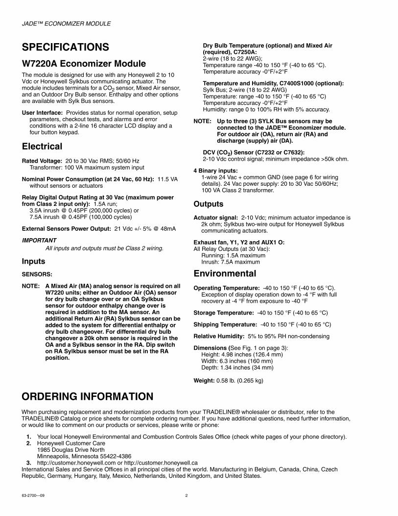
Dimensions (See Fig. 1 on page 3):Height: 4.98 inches (126.4 mm)Width: 6.3 inches (160 mm)Depth: 1.34 inches (34 mm)
Weight: 0.58 lb. (0.265 kg)

JADE™ ECONOMIZER MODULE
3 63-2700—09
Approvals: UL listed (XAPX) for USA and Canada;California Energy Commission (CEC) FDD ID number HJW10.
Fig. 1. Dimensions in inches (mm) showing mounting holes.
Accessories— 50048926-001 2-pin edge connector for sensors (20
pieces per bag)— 50048926-002 6-pin edge connector for field wiring (20
pieces per bag) — C7250A 20k sensor for MA or OA (dry bulb changeover)— C7400S Sylkbus sensor for enthalpy control in OA and/
or RA and RA for differential dry bulb changeover— W7220 PCMOD interface tool for JADE controller and
Personal Computer. Go to www.customer.honey-well.com/economizertools for the software
— 50053060-001 Duct mounting kit for sensors— C7632 or C7232 CO2 sensors
BEFORE INSTALLATIONReview the “Specifications” on page 2 before installing the The JADE™ Economizer System.
When Installing This Product1. Read these instructions carefully. Failure to follow them
could damage the product or cause a hazardous condi-tion.
2. Check ratings given in instructions and on the product to ensure the product is suitable for your application.
3. Installer must be a trained, experienced service technician.
4. After installation is complete, check out product operation as provided in these instructions.
NOTE: Jade will be in the "set up" mode for the first 60 minutes after powered. If a sensor for OA air or Sylkbus device (sensor, actuator) is disconnected during the set up mode, the Jade will not alarm that failure. The MA sensor is a system "critical" sensor, if the MA sensor is removed during the set up mode, the Jade will alarm. After 60 minutes the Jade controller will change to operation mode and all components removed or failed will alarm in the operation mode.
INSTALLATION AND SETUPThe following installation procedures should be performed in the order listed:
1. Mounting — see page 3.2. Wiring — see page 4.3. Interface and Programming overview – see page 18.4. Setup and Configuration — see page 185. Checkout — see page 31.
Troubleshooting and Alarms—see page 32.
MOUNTINGThis section describes the mounting procedures for the JADE™ Economizer module and the sensors.
Economizer Module Location and MountingIMPORTANT
Avoid mounting in areas where acid fumes or other deteriorating vapors can attack the metal parts of the module’s circuit board, or in areas where escaping gas or other explosive vapors are present.
IMPORTANTThe module must be mounted in a position that allows clearance for wiring, servicing, and removal.
Mount the Economizer module on any convenient interior location using the two mounting holes provided on the enclosure using #6 or #8 screws (screws are not provided and must be obtained separately). Use the dimensions in Fig. 1 on page 3 as a guide.
The Economizer module may be mounted in any orientation. However, mounting in the orientation shown in Fig. 1 on page 3 permits proper viewing of the LCD display and use of the keypad.
Sensor Location and MountingThe JADE™ Economizer W7220 uses digital and communicating sensors for control. The C7250 temperature sensors (MAa and OAb) are 20k NTC. A MA sensor is required for all applications and is mounted in the mixed air section of a rooftop unit either directly to the sheet metal using self tapping sheet metal screws or in the air stream using the duct mounting kit. Duct mount kit is part number 50053060-001.
Optional OA, RAc and DAd Sylkbus sensors communicate with the W7220 on the two-wire communication bus and can either be wired using a two pin header or using a side connector. Each Sylkbus sensor includes a two pin side connector with the packaging. The SKU number of the Sylkbus sensor is C7400S. All OA, RA and DA sensors are the same SKU
4-63/64(126)
6-19/64 (160)
MOUNTING HOLE (X2)M32273A
3-5/32 (80)
a MA = Mixed Air b OA = Outdoor Air c RA = Return Air d DA = Discharge Air
JADE™ ECONOMIZER MODULE
63-2700—09 4
number. The sensor is set for the appropriate type of sensing using the three position DIP switch located on the sensor. OA position is OFF, OFF, OFF; RA is ON, OFF, OFF and DA is OFF, ON, OFF. During installation the sensors are set for the usage desired. See “Sylk Bus Sensor Wiring” on page 7 for DIP switch details.
NOTE: The protective film on the dip switch is only nec-essary during the factory assembly process. Sim-ply push through the film to set the dip switches; this will not harm the device.
Once installed, a sensor can be changed to a different application by simply changing the DIP switch setting.
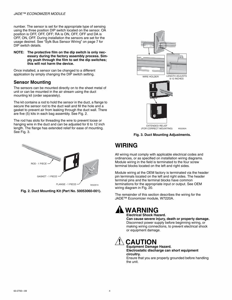
Sensor MountingThe sensors can be mounted directly on to the sheet metal of unit or can be mounted in the air stream using the duct mounting kit (order separately).
The kit contains a rod to hold the sensor in the duct, a flange to secure the sensor rod to the duct wall and fill the hole and a gasket to prevent air from leaking through the duct wall. There are five (5) kits in each bag assembly. See Fig. 2.
The rod has slots for threading the wire to prevent loose or hanging wire in the duct and can be adjusted for 6 to 12 inch length. The flange has extended relief for ease of mounting. See Fig. 3.
Fig. 2. Duct Mounting Kit (Part No. 50053060-001).
Fig. 3. Duct Mounting Adjustments.
WIRINGAll wiring must comply with applicable electrical codes and ordinances, or as specified on installation wiring diagrams. Module wiring in the field is terminated to the four screw terminal blocks located on the left and right sides.
Module wiring at the OEM factory is terminated via the header pin terminals located on the left and right sides. The header terminal pins and the terminal blocks have common terminations for the appropriate input or output. See OEM wiring diagram in Fig. 20.
The remainder of this section describes the wiring for the JADE™ Economizer module, W7220A.
WARNINGElectrical Shock Hazard.Can cause severe injury, death or property damage.Disconnect power supply before beginning wiring, or making wiring connections, to prevent electrical shock or equipment damage.
CAUTIONEquipment Damage Hazard.Electrostatic discharge can short equipment circuitry.Ensure that you are properly grounded before handling the unit.
ROD - 1 PIECE
FLANGE - 1 PIECE
GASKET - 1 PIECE
M32281A
WIRE HOLDER
EXTENDED RELIEF(FOR CORRECT MOUNTING) M32282A
LENGTH ADJUSTS6-12 INCHES

JADE™ ECONOMIZER MODULE
5 63-2700—09
Fig. 4. Location of Outdoor Air, Return Air, Mixed Air, and Discharge Air Sensors in an economizer system.
DISCHARGEAIR SENSOR
C7400S
DIRECT EXPANSIONCOIL
C7400S
ENTHALPYSENSOR
C7400SENTHALPYSENSOR
RETURN AIR
OUTDOORAIR
C7250A
MIXED AIRSENSOR
TWO STAGE COOL PROGRAMMABLE THERMOSTAT
FOR DIFFERENTIAL ENTHALPY, THE TWO C7400S ENTHALPY SENSORS ARE CONNECTED TO THE W7720A ECONOMIZER CONTROL ONE IS MOUNTED IN RETURN AIR, AND THE OTHER IS MOUNTED IN OUTDOOR AIR. DIFFERENTIAL ENTHALPY CONTROL PROVIDES GREATER ENERGY SAVINGS THAN SINGLE ENTHALPY.
M35163
1
1
1
MS3103J MS3105JMS7505 ACTUATOR
W7720A

JADE™ ECONOMIZER MODULE
63-2700—09 6
Economizer Module Wiring MethodWire the sensors and outputs, then wire the power connection.
Each terminal can accommodate the following gauges of wire:• Single wire – from 18 AWG to 22 AWG solid or stranded• Multiple wires – up to two 22 AWG stranded• For the 24 Vac connections: single wire – from 14 to 18
AWG solid or stranded• For S-BUS wiring, the sensors may be mounted up to 200
ft. (61 m) from the JADE controller. When the length of wire is over 100 feet use twisted pair shielded wire.
• All sensor wiring to the Sylk bus and analog sensors is polarity insensitive.
Prepare wiring for the terminal blocks, as follows:1. Remove the plastic tabs from the side of the controller
where the connectors will slide onto the PWA.2. Strip 1/2 in. (13 mm) insulation from the conductor.3. Cut a single wire to 3/16 in. (5 mm). Insert the wire in the
required terminal location and tighten the screw.4. If two or more wires are being inserted into one terminal
location, twist the wires together a minimum of three turns before inserting them to ensure proper electrical contact. See Fig. 5 on page 6.
5. Cut the twisted end of the wires to 3/16 in. (5 mm) before inserting them into the terminal and tightening the screw.
6. Pull on each wire in all terminals to check for good mechanical connection.
Fig. 5. Attaching two or more wires at terminal blocks.
Economizer Module Wiring DetailsThe wiring connection terminals for each module/sensor are:• “JADE™ Economizer Module Wiring” on this page.• “Sylk Bus Sensor Wiring” on page 7.
JADE™ Economizer Module WiringUse Fig. 6 and Tables 1 and 2 to locate the wiring terminals for the Economizer module.
NOTE: The four terminal blocks are removable. You can slide out each terminal block, wire it, and then slide it back into place.
Fig. 6. W7220 Economizer module terminal connection labels.
1/2 (13)
1. STRIP 1/2 IN. (13 MM) FROM WIRES TO BE ATTACHED AT ONE TERMINAL.
2. TWIST WIRES TOGETHER WITH PLIERS (A MINIMUM OF THREE TURNS).
3. CUT TWISTED END OF WIRES TO 3/16 IN. (5 MM) BEFORE INSERTING INTO TERMINAL AND TIGHTENING SCREW. THEN PULL ON EACH WIRE IN ALL TERMINALS TO CHECK FOR GOOD MECHANICAL CONNECTION.
M24382A
Table 1. Economizer Module - Left hand terminal blocks.
Label Type Description
Top Left Terminal Block
MATMAT
20k NTC andCOM
Mixed Air Temperature Sensor(polarity insensitive connection)
OATOAT
20k NTC and COM
Outdoor Air Temperature Sensor(polarity insensitive connection)
S-BUSS-BUS
SYLK Bus Sylk Bus sensor (polarity insensitive connection)
Bottom Left Terminal Block
IAQ 2-10 2-10 Vdc Air Quality Sensor Input (e.g. CO2 sensor)
IAQ COM COM Air Quality Sensor Common
IAQ 24V 24 Vac Air Quality Sensor 24 Vac Source
ACT 2-10 2-10 Vdc Damper Actuator Output (2-10 Vdc)
ACT COM COM Damper Actuator Output Common
ACT 24V 24 Vac Damper Actuator 24 Vac Source
n/a The bottom pin is not used.
JADE CONTROLLER
LEFT TERMINAL BLOCK LABEL
NOTE: THE BOTTOM 4 PIN ACTUATOR HEADER IS NOT USED.
RIGHT TERMINALBLOCK LABEL
M32283C
AUX2-I
AUX1-O
AUX2-I
OCC
E-GND
EXH1
AUX1-O
Y2-I
Y2-O
Y1-I
Y1-O
C
R

JADE™ ECONOMIZER MODULE
7 63-2700—09
Sylk Bus Sensor WiringThe labels on the sensors and controller are color coded for ease of installation. Orange labeled sensors can only be wired to orange terminals on the controller. Brown labeled sensors can only be wired to S-bus (brown) terminals. Use Fig. 7 and Table 3 to locate the wiring terminals for each Sylk Bus sensor.
Use Fig. 7 and Table 4 to set the DIP switches for the desired use of the sensor.
Fig. 7. Sylk Bus sensor DIP switches.
NOTE: When using the Sylkbus sensors there will be a slight delay while the Jade controller and the sen-sor communicate. Analog sensors do not commu-nicate on the Sylkbus and output a 20k ohm signal to the Jade controller so the response time is instantaneous.
Table 2. Economizer Module - Right hand terminal blocks.
Label Type Description
Top Right Terminal Block
n/a The first pin is not used
AUX2 I 24 Vac IN Shut Down (SD) or Heat (W) Conventional only or Heat Pump Changeover (O/B) in Heat Pump mode.
OCC 24 Vac IN Occupied / Unoccupied Input
E-GND EGND Earth Ground - System Required
EXH1 24 Vac OUT Exhaust Fan 1 Output
AUX1 O 24 Vac OUT Programmable: Exhaust fan 2 output or ERV or System Alarm output.
Bottom Right Terminal Block
Y2-I 24 Vac IN Y2 in - Cooling Stage 2 Input from space thermostat
Y2-O 24 Vac OUT Y2 out - Cooling Stage 2 Output to stage 2 mechanical cooling
Y1-I 24 Vac IN Y1 in - Cooling Stage 1 Input from space thermostat
Y1-O 24 Vac OUT Y1 out - Cooling Stage 1 Output to stage 1 mechanical cooling
C COM 24 Vac Common
R 24 Vac 24 Vac Power (Hot)
Table 3. SYLK Bus Sensor Wiring Terminations.
Terminal
Type DescriptionNbr Label
1 S-BUS SYLK Bus
Sylk Bus Communications (Sensor Bus) polarity insensitive
2 S-BUS SYLK Bus
Sylk Bus Communications (Sensor Bus) polarity insensitive
Table 4. SYLK Bus Sensor DIP Switch Settings.
Use
DIP Switch Positions for Switches 1, 2, & 3
1 2 3
DAa
a DA = Discharge Air
OFF ON OFF
RAb
b RA = Return Air
ON OFF OFF
OAc
c OA = Outdoor Air
OFF OFF OFF
DIP SWITCHLABEL
M32271B
SYLK BUS TERMINALS (1 AND 2)
DIP SWITCHES(3)
SYLK BUS 2 PIN SIDE CONNECTOR
JADE™ ECONOMIZER MODULE
63-2700—09 8
Actuator Wiring Options:1. The JADE economizer controller can only have one (1)
communicating actuator connected to it.2. Up to four (4) non-communicating and two (2) 2-position
actuators (1 each on EXH1 and AUX1 O)3. One (1) communicating and up to four (4) non-communi-
cating and two (2) 2-position actuators (1 each on EXH1 and AUX1 O). When using a 2-position actuator on the AUX1 O, the AUX1 O must be programmed for Exh2 and the % open is the % open of the outdoor damper when the 2-pos actuator opens. Connect 24 V to Exh1 and/or AUX1 O and ground to the Jade "C" terminal.
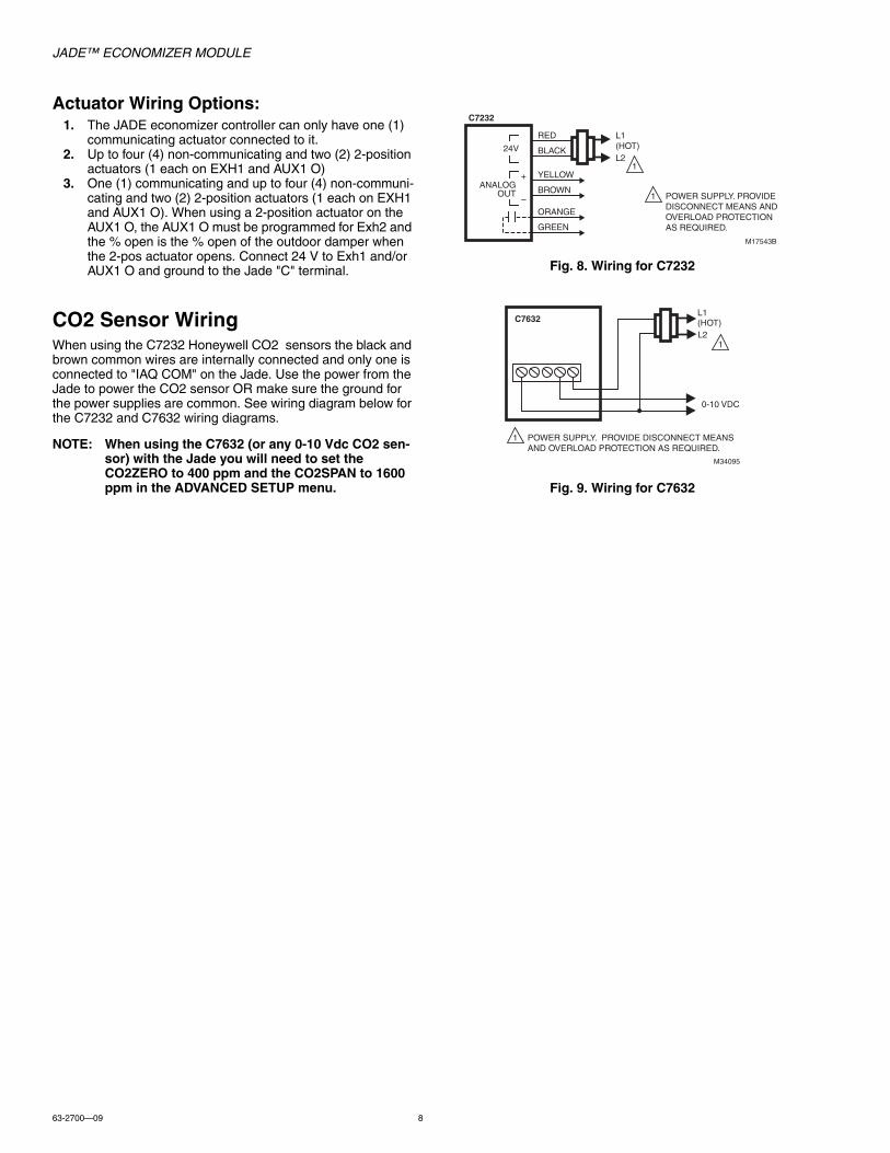
CO2 Sensor WiringWhen using the C7232 Honeywell CO2 sensors the black and brown common wires are internally connected and only one is connected to "IAQ COM" on the Jade. Use the power from the Jade to power the CO2 sensor OR make sure the ground for the power supplies are common. See wiring diagram below for the C7232 and C7632 wiring diagrams.
NOTE: When using the C7632 (or any 0-10 Vdc CO2 sen-sor) with the Jade you will need to set the CO2ZERO to 400 ppm and the CO2SPAN to 1600 ppm in the ADVANCED SETUP menu.
Fig. 8. Wiring for C7232
Fig. 9. Wiring for C7632
L1 (HOT)L2
M17543B
1
1 POWER SUPPLY. PROVIDE DISCONNECT MEANS AND OVERLOAD PROTECTION AS REQUIRED.
C7232
24V
YELLOW
BLACK
RED
BROWN
ORANGE
GREEN
ANALOGOUT
+
–
L1 (HOT)
0-10 VDC
L2
M34095
1
1 POWER SUPPLY. PROVIDE DISCONNECT MEANS AND OVERLOAD PROTECTION AS REQUIRED.
C7632

JADE™ ECONOMIZER MODULE
9 63-2700—09
WIRING APPLICATION EXAMPLESThis section shows the wiring configurations for the JADE™ Economizer system.
Stand-alone EconomizerThe most basic configuration is the stand-alone Economizer (see Fig. 10 and Fig. 15).
A stand-alone Economizer is directly wired to sensors, actuators, thermostat, and mechanical cooling controls in the roof top unit. It does not require Sylk Bus communications.
Fig. 10. Stand-alone dry bulb Economizer configuration with black motor M7215.
Fig. 11. 2-position actuator.
ROOF TOP UNIT
Y1O
Y2OY1I
Y2I
OCC
24 VAC
1K1
1K1
E-GND
Y1 G
W2
W1
Y2
O/B
OCC
W7220 ECONOMIZER CONTROLLER MODULE
THERMOSTAT
CO2SENSOR2-10 VDC
(OPTIONAL)
MAMAOATOAT
C R
M28980D
IAQ (2-10V)IAQ COMIAQ 24V
ACT (2-10V)ACT COMACT 24V
AUX1-0
AUX2-I
OA TEMPSENSOR20K NTC
M7215
NOTE THAT THE C7250 20K NTC SENSOR CAN BE MOUNTED IN THE OAT ONLY IN THIS CONFIGURATION.1
WHEN USING A HEAT PUMP THERMOSTAT, THERMOSTAT TERMINALS MAY DIFFER: W1 MAY BE LABELED O OR B AND W2 MAY BE LABELED W.
WHEN USING A HEAT PUMP WITH DEFROST FEEDBACK, ADD AN ISOLATION RELAY BETWEEN O AND C.
2
3
3
1
MA TEMPSENSOR20K NTC
+
-
TR1
TR
IN
IN
2
R(+)
C(-)
1
2
ACTUATOR
EXH1 OR AUX1 O
NOTE: ON/OFF ACTUATORS CAN BE USED ON THE EXH1 OR AUX1 O TERMINAL WITH GROUND TO THE C TERMINAL. WHEN PROGRAMMING THE EXH1 OR AUX1 O, THE % IS THE PERCENT OPEN POSITION OF THE OUTDOOR AIR DAMPER WHEN THE EXH1 OR AUX1 O TERMINAL IS ENERGIZED AND THE 2-POS DAMPER GOES OPEN. IF USING THE AUX1 O TERMINAL PROGRAM AUX1 O FOR EXH2.
C
M33409
V

JADE™ ECONOMIZER MODULE
63-2700—09 10
Fig. 12. Prestige and EIM with communicating actuator.
M35158
TO THERMOSTAT
STATUSLEDS
SENSORS
CONVPOWER
HEAT
COOL
FAN
U1
U2
U3 A
EIM
JADE W7220A1000
ON JADE CONTROLLER:1. Y2-O CONNECT TO STAGE 2 MECHANICAL COOLING2. Y1-O CONNECT TO STAGE 1 MECHANICAL COOLING3. MAT IS MIXED AIR SENSOR C7250A10014. OAT IS TEMPERATURE CHAGEOVER C7250A1001 SENSOR OR S-BUS OA ENTHALPY SENSOR C7400S10005. AUX1 OUT PROGRAM TO SYS IN SYSTEM SETUP MENU
OCCE-GND
AUX1 OUT
AUX2-I
Y1O
Y2OY1I
Y2I
C
TRANSFORMER
24VAC
120VAC
C
R
R
12345
KIT WITH PRESTIGE AND EIMYTHX9421R5051
EIMTHM5421R1013
RELAYR822N1011
MS3103J1030COMMUNICATING DCA
1 3
PRESTIGETHX9421R5013
CR
1
THE TRANSFORMER NEEDS TO BE 100VA.
1

JADE™ ECONOMIZER MODULE
11 63-2700—09
Fig. 13. Jade with Prestige IAQ thermostat, communicating actuator, CO2 and VFD.
C7400SOUTSIDE AIRTEMP/HUMIDITY(ENTHALPY)SYLKBUS SENSOR
C7400SRETURN AIRTEMP/HUMIDITY(ENTHALPY)SYLKBUS SENSOR
ROOF TOP UNIT
Y1O
Y2OY1I
Y2I
OCCE-GND
Y1 G
W2
W1
Y2
O/B
OCC
W7220 ECONOMIZER CONTROLLER MODULE
THERMOSTAT
C R
C(-)
M35159
S-BUSS-BUS
MATMAT
CO2SENSOR2-10 VDC
(OPTIONAL)
IAQ (2-10V)IAQ COMIAQ 24VACT (2-10V)ACT COMACT 24V
MA TEMPSENSOR20K NTC
AUX1-0
AUX2-I
3
1
2
MS3103J OR MS3105JS-BUS
4
5
S-BUS
R(+)24 VAC
8
1K1
1K1
1
2
3
4
I/O BOARD ON SMARTVFDHVAC DRIVE HVFDSD
G
C
Y2
Y1
W1
Y1
W1Y2
G
Y2
W1
CC
C C
6
14
C
RELAY 1, DPDT RELAY, NO CONTACTS ENERGIZE DIGITAL INPUT 4 FOR HIGH SPEED FAN WITH W1 CALL.
RELAY 2, DPST RELAY, NO CONTACTS ENERGIZE DIGITAL INPUT 4 FOR HIGH SPEED FAN WITH Y2 CALL.
RELAY 3, SPST RELAY, NO CONTACTS ENERGIZE DIGITAL INPUT 1 FOR LOW SPEED FAN WITH Y1 CALL.
RELAY 4, SPST RELAY, NO CONTACTS ENERGIZE DIGITAL INPUT 1 FOR LOW SPEED FAN WITH G CALL.
LOW SPEED FAN IS CONFIGURED BY SETTING “MINIMUM FREQUENCY” WITH PARAMETER M1.8 OF THE STARTUP WIZARD OF THE SMARTVFD HVAC.
HIGH SPEED FAN IS CONFIGURED BY SETTING “PRESET FREQUENCY 1” WITH PARAMETER M3.3.12 OF THE SMARTVFD HVAC.
WHEN USING A HEAT PUMP THERMOSTAT, THERMOSTAT TERMINALS MAY DIFFER: W1 MAY BE LABELED O OR B AND W2 MAY BE LABELED W.
WHEN USING A HEAT PUMP WITH DEFROST FEEDBACK, ADD AN ISOLATION RELAY BETWEEN O AND C.
NOTES: SEE INSTALLATION INSTRUCTIONS62-0331 FOR SPECIFIC W7220 JADE WIRING INFORMATION.
3421
5
6
5
6
1 +10 Vref REFERENCE OUTPUT
2 AI1+ ANALOG INPUT,VOLTAGE OR CURRENT*
VOLTAGE3 AI1- ANALOG INPUT COMMON
(CURRENT)4 AI2+ ANALOG INPUT,
VOLTAGE OR CURRENTCURRENT
5 AI2 ANALOG INPUT COMMON (CURRENT)
6 24Vou 24V AUX. VOLTAGE
7 GND I/O GROUND
8 DI1 DIGITAL INPUT 1 START FWD
9 DI2 DIGITAL INPUT 2START REV
10 DI3 DIGITAL INPUT 3 FAULT
11 CM COMMON A FOR DIN1-DIN6**
12 24Vout 24V AUX. VOLTAGE
13 GND I/O GROUND
14 DI4 DIGITAL INPUT PRESET FREQ SELECT 1
15 DI5 DIGITAL INPUT PRESET FREQ
SELECT 2
16 DI6 DIGITAL INPUT 6 FAULT RESET17 C COMMON A FOR DIN1-DIN6**
18 AO1 ANALOG SIGNAL (+OUTPUT)OP FREQ
19 AO-/GND ANALOG OUTPUT COMMON
30 +24 Vin 24V AUXILIARY INPUT VOLTAGE
A RS485 DIFFERENTIAL RECEIVER/TRANSMITTER
B RS485 DIFFERENTIAL RECEIVER/TRANSMITTER
BASIC I/O BOARD
TERMINAL SIGNAL DEFAULT
8
7
8
7

JADE™ ECONOMIZER MODULE
63-2700—09 12
Fig. 14. Jade with Prestige IAQ thermostat and EIM, communicating actuator, CO2 and VFD.
M35157
TO THERMOSTAT
STATUSLEDS
SENSORS
CONVPOWER
HEAT
COOL
FAN
U1
U2
U3 A
EIM
JADE W7220A1000
ON JADE CONTROLLER:1. Y2-O CONNECT TO STAGE 2 MECHANICAL COOLING2. Y1-O CONNECT TO STAGE 1 MECHANICAL COOLING3. MAT IS MIXED AIR SENSOR C7250A10014. OAT IS TEMPERATURE CHAGEOVER C7250A1001 SENSOR OR S-BUS OA ENTHALPY SENSOR C7400S10005. AUX1 OUT PROGRAM TO SYS IN SYSTEM SETUP MENU
OCCE-GND
AUX1 OUT
AUX2-I
Y1O
Y2OY1I
Y2I
C
TRANSFORMER
24VAC
120VAC
C
R
R
TR
ININ
PRESTIGETHX9421R5013
KIT WITH PRESTIGE AND EIMYTHX9421R5051
EIMTHM5421R1013
RELAYR822N1011
1 3
TR1+
–
M7215
ACT (2-10V)ACT COMACT 24V
CR
THE TRANSFORMER NEEDS TO BE 100VA.
1
1

JADE™ ECONOMIZER MODULE
13 63-2700—09
EXH1 and EXH2 wiring:Relay Digital Output Rating at 30 Vac (maximum powerfrom Class 2 input only): 1.5A run;
3.5A inrush @ 0.45PF (200,000 cycles) or7.5A inrush @ 0.45PF (100,000 cycles)
If the inrush or FLA amps is above listed limits OR if the fan is a line voltage fan, an external relay will be required.
If no relay is required, the EXH1 or AUX1 out is wired to one side of the fan and the other side is wired to system common "C" on the W7220 or equipment terminal board. (W7220 powered off the system transformer).
If a relay is required, the coil of the relay would be wired between the EXH1 or AUX1 and the C terminal of the W7220.
Fig. 15. Stand-alone dry-bulb Economizer configuration with Honeywell MS7503 or MS7505 Direct Coupled Actuator.
ROOF TOP UNIT
Y1O
Y2OY1I
Y2I
OCC
24 VAC
E-GND
Y1 G
W2
W1
Y2
O/B
OCC
W7220 ECONOMIZER CONTROLLER MODULE
THERMOSTAT
CO2SENSOR2-10 VDC
(OPTIONAL)
MATMAT
OATOAT
C R
M32564D
IAQ (2-10V)IAQ COMIAQ 24V
ACT (2-10V)ACT COMACT 24V
3
OAT TEMPSENSOR20K NTC
MS7503 OR MS7505
NOTE THAT THE 20K NTC SENSOR CAN BE MOUNTED IN THE OAT TERMINALS ONLY IN THIS CONFIGURATION.
WHEN USING A HEAT PUMP THERMOSTAT, THERMOSTAT TERMINALS MAY DIFFER: W1 MAY BE LABELED O OR B AND W2 MAY BE LABELED W.
WHEN USING A HEAT PUMP WITH DEFROST FEEDBACK, ADD AN ISOLATION RELAY BETWEEN O AND C.
1
1
MA TEMPSENSOR20K NTC
R(+)
C(-)
AUX1-0
AUX2-I
2
3
2
3
1K1
1K1

JADE™ ECONOMIZER MODULE
63-2700—09 14
Fig. 16. Stand-alone dry-bulb Economizer configuration with Honeywell MS3103J or MS3105J communicating actuators.
ROOF TOP UNIT
Y1O
Y2OY1I
Y2I
OCC
24 VAC
E-GND
Y1 G
W2
W1
Y2
O/B
OCC
W7220 ECONOMIZER CONTROLLER MODULE
THERMOSTAT
CO2SENSOR2-10 VDC
(OPTIONAL)
MATMAT
OATOAT
C R
R(+)
C(-)
M32650D
IAQ (2-10V)IAQ COMIAQ 24V
ACT (2-10V)ACT COMACT 24V
3
1
2
OAT TEMPSENSOR20K NTC
MS3103J OR MS3105J
1
1
MA TEMPSENSOR20K NTC
S-BUS
4
5
S-BUS
AUX1-0
AUX2-I
NOTE THAT THE 20K NTC SENSOR CAN BE MOUNTED IN THE OAT TERMINALS ONLY IN THIS CONFIGURATION.
WHEN USING A HEAT PUMP THERMOSTAT, THERMOSTAT TERMINALS MAY DIFFER: W1 MAY BE LABELED O OR B AND W2 MAY BE LABELED W.
WHEN USING A HEAT PUMP WITH DEFROST FEEDBACK, ADD AN ISOLATION RELAY BETWEEN O AND C.
2
2
3
3
1K1
1K1
JADE™ ECONOMIZER MODULE
15 63-2700—09
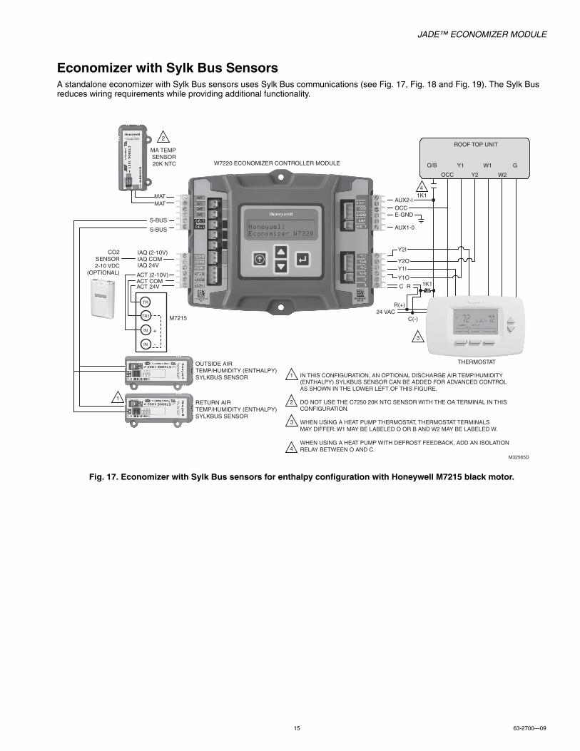
Economizer with Sylk Bus SensorsA standalone economizer with Sylk Bus sensors uses Sylk Bus communications (see Fig. 17, Fig. 18 and Fig. 19). The Sylk Bus reduces wiring requirements while providing additional functionality.
Fig. 17. Economizer with Sylk Bus sensors for enthalpy configuration with Honeywell M7215 black motor.
S-BUS
S-BUS
OUTSIDE AIRTEMP/HUMIDITY (ENTHALPY)SYLKBUS SENSOR
RETURN AIRTEMP/HUMIDITY (ENTHALPY)SYLKBUS SENSOR
ROOF TOP UNIT
Y1O
Y2OY1I
Y2I
OCCE-GND
Y1 G
W2
W1
Y2
O/B
OCC
W7220 ECONOMIZER CONTROLLER MODULE
THERMOSTAT
MATMAT
C R
R(+)
C(-)
M32565D
IN THIS CONFIGURATION, AN OPTIONAL DISCHARGE AIR TEMP/HUMIDITY (ENTHALPY) SYLKBUS SENSOR CAN BE ADDED FOR ADVANCED CONTROL AS SHOWN IN THE LOWER LEFT OF THIS FIGURE.
DO NOT USE THE C7250 20K NTC SENSOR WITH THE OA TERMINAL IN THISCONFIGURATION.
WHEN USING A HEAT PUMP THERMOSTAT, THERMOSTAT TERMINALS MAY DIFFER: W1 MAY BE LABELED O OR B AND W2 MAY BE LABELED W.
WHEN USING A HEAT PUMP WITH DEFROST FEEDBACK, ADD AN ISOLATION RELAY BETWEEN O AND C.
1
4
1
2
CO2SENSOR2-10 VDC
(OPTIONAL)
IAQ (2-10V)IAQ COMIAQ 24V
ACT (2-10V)ACT COMACT 24V
+
-
TR1
TR
IN
IN
M7215
MA TEMPSENSOR20K NTC
AUX1-0
AUX2-I
3
2
4
3
1K1
1K1
24 VAC

JADE™ ECONOMIZER MODULE
63-2700—09 16
Fig. 18. Economizer with Sylk Bus sensors for enthalpy configuration with a Honeywell MS7503 or MS7505 Direct Coupled Actuator.
OUTSIDE AIRTEMP/HUMIDITY (ENTHALPY)SYLKBUS SENSOR
RETURN AIRTEMP/HUMIDITY (ENTHALPY)SYLKBUS SENSOR
ROOF TOP UNIT
Y1O
Y2OY1I
Y2I
OCCE-GND
Y1 G
W2
W1
Y2
O/B
OCC
W7220 ECONOMIZER CONTROLLER MODULE
THERMOSTAT
C R
R(+)
C(-)
M32566D
IN THIS CONFIGURATION, AN OPTIONAL DISCHARGE AIR TEMP/HUMIDITY (ENTHALPY) SYLKBUS SENSOR CAN BE ADDED FOR ADVANCED CONTROL AS SHOWN IN THE LOWER LEFT OF THIS FIGURE.
DO NOT USE THE C7250 20K NTC SENSOR WITH THE OA TERMINAL IN THISCONFIGURATION.
WHEN USING A HEAT PUMP THERMOSTAT, THERMOSTAT TERMINALS MAY DIFFER: W1 MAY BE LABELED O OR B AND W2 MAY BE LABELED W.
WHEN USING A HEAT PUMP WITH DEFROST FEEDBACK, ADD AN ISOLATION RELAY BETWEEN O AND C.
1
1
2
MS7503 OR MS7505
3
S-BUSS-BUS
MATMAT
CO2SENSOR2-10 VDC
(OPTIONAL)
IAQ (2-10V)IAQ COMIAQ 24VACT (2-10V)ACT COMACT 24V
MA TEMPSENSOR20K NTC
AUX1-0
AUX2-I
2
3
4
3
4
1K1
1K1
24 VAC

JADE™ ECONOMIZER MODULE
17 63-2700—09
Fig. 19. Economizer with Sylk Bus sensors for enthalpy configuration with a Honeywell MS3103J or MS3105J communicating actuators.
Fig. 20. OEM wiring harness information. Refer to previous wiring diagrams for detailed application wiring.
C7400SOUTSIDE AIRTEMP/HUMIDITY (ENTHALPY)SYLKBUS SENSOR
C7400SRETURN AIRTEMP/HUMIDITY (ENTHALPY)SYLKBUS SENSOR
ROOF TOP UNIT
Y1O
Y2OY1I
Y2I
OCCE-GND
Y1 G
W2
W1
Y2
O/B
OCC
W7220 ECONOMIZER CONTROLLER MODULE
THERMOSTAT
C R
C(-)
M32653D
IN THIS CONFIGURATION, AN OPTIONAL DISCHARGE AIR TEM/HUMIDITY (ENTHALPY) SYLKBUS SENSOR CAN BE ADDED FOR ADVANCED CONTROL AS SHOWN IN THE LOWER LEFT OF THIS FIGURE.
1
1
THE S-BUS COMPONENTS MAY BE DAISY CHAINED TO ANOTHER S-BUS COMPONENT.
WHEN USING A HEAT PUMP THERMOSTAT, THERMOSTAT TERMINALS MAY DIFFER: W1 MAY BE LABELED O OR B AND W2 MAY BE LABELED W.
WHEN USING A HEAT PUMP WITH DEFROST FEEDBACK, ADD AN ISOLATION RELAY BETWEEN O AND C.
2
S-BUSS-BUS
MATMAT
CO2SENSOR2-10 VDC
(OPTIONAL)
IAQ (2-10V)IAQ COMIAQ 24VACT (2-10V)ACT COMACT 24V
MA TEMPSENSOR20K NTC
AUX1-0
AUX2-I
3
1
2
MS3103J OR MS3105JS-BUS
4
5
S-BUS
2
R(+)24 VAC
3
3
4
1K1
1K1
4
AUX1 OUT
JADE CONTROLLER2-PIN CONNECTORNEEDED (VHR-2N)
MATMATOATOATS-BUSS-BUSS-BUSS-BUSS-BUSS-BUS
IAQ 2-10IAQ COMIAQ 24V+ACT 2-10ACT COMACT 24V+NOT USED
LEFT TERMINAL BLOCK LABEL
RIGHT TERMINALBLOCK LABEL
M31402E
NOT USEDAUX2-1
OCCE-GNDEXH1
AUX1-O
Y2-IY2-OY1-I
Y1-ORC
3-PIN CONNECTORNEEDED (VHR-3N)
4-PIN CONNECTORNEEDED (VHR-4N)
6-PIN CONNECTORNEEDED (VHR-6N)
PART NUMBER PIN COUNT MANUFACTURER JST VH CONNECTOR PLASTIC HOUSING VHR-2N PLUS 2 PIECES SVH-21T-P1.1 METAL CONTACT 2 JST VH JST VH CONNECTOR PLASTIC HOUSING VHR-3N PLUS 3 PIECES SVH-21T-P1.1 METAL CONTACT 3 JST VH JST VH CONNECTOR PLASTIC HOUSING VHR-4N PLUS 4 PIECES SVH-21T-P1.1 METAL CONTACT 4 JST VH JST VH CONNECTOR PLASTIC HOUSING VHR-6N PLUS 6 PIECES SVH-21T-P1.1 METAL CONTACT 6 JST VH TYPE 42743-2 1 AMP 1/4 INCH QUICK CONNECT FOR M7215 BLACK MOTORNOTE: THOSE ARE NOT HONEYWELL PART NUMBERS. TO PLACE AN ORDER - CONTACT YOUR SALES REPRESENTATIVE.
AUX2 IN
AUX1-O
AUX2-I
OCC
E-GND
EXH1
Y2-I
Y2-O
Y1-I
Y1-O
C
R

JADE™ ECONOMIZER MODULE
63-2700—09 18
INTERFACE OVERVIEWThis section describes how to use the Economizer’s user interface for:• Keypad and menu navigation• Settings and parameter changes• Menu structure and selection
User InterfaceThe user interface consists of an LCD display and a 4-button keypad on the front of the Economizer module. The LCD is a 16 character by 2 line dot matrix display.
Fig. 21. Economizer LCD and Keypad Layout.
KeypadThe four navigation buttons illustrated in Fig. 21 are used to scroll through the menus and menu items, select menu items, and to change parameter and configuration settings.
Using the Keypad with MenusTo use the keypad when working with menus:• Press the button to move to the previous menu.• Press the button to move to the next menu.
• Press the button (Enter) to display the first item in the currently displayed menu.
• Press the button (Menu up) to exit a menu’s item and return to the list of menus.
Using the Keypad with Settings and ParametersTo use the keypad when working with Setpoints, System and Advanced Settings, Checkout tests, and Alarms:• Navigate to the desired menu.
• Press the button (Enter) to display the first item in the currently displayed menu.
• Use the and buttons to scroll to the desired parameter.
• Press the button (Enter) to display the value of the currently displayed item.
• Press the button to increase (change) the displayed parameter value.a
• Press the button to decrease (change) the displayed parameter value.a
• Press the button to accept the displayed value and store it in non-volatile RAM.
• CHANGE STORED displays.
• Press the button (MenuUp/Exit) to return to the
previous menu.a When values are displayed, pressing and holding the or
button causes the display to automatically increment.
Menu StructureTable 5 on page 19 illustrates the complete hierarchy of menus and parameters for the JADE™ Economizer system.
The Menus in display order are:• STATUS• SETPOINTS• SYSTEM SETUP• ADVANCED SETUP• CHECKOUT• ALARMS
IMPORTANTTable 5 on page 19 illustrates the complete hierarchy. Your menu parameters will be different depending on your configuration.
For example if you do not have a DCV (CO2) sensor, then none of the DCV parameters appear and only MIN POS will display. If you have a CO2 sensor, the DCV MIN and DCV MAX will appear AND if you have 2 speed fan DCV MIN (high and low speed) and DCV MAX (high and low speed will appear).
SETUP AND CONFIGURATIONBefore being placed into service, the JADE™ Economizer module must be setup and configured for the installed system.
IMPORTANTDuring setup, the Economizer module is live at all times.
The setup process uses a hierarchical menu structure that is easy to use. You press the and arrow buttons to move forward and backward through the menus and press the button to select and confirm setup item changes.
Time-out and ScreensaverWhen no buttons have been pressed for 10 minutes, the LCD displays a screen saver, which cycles through the Status items. Each Status items displays in turn and cycles to the next item after 5 seconds.
M32274A
2 LINELCD
SELECT (ENTER)BUTTONSCROLL
(UP/DOWN)BUTTONS
MENU UP(EXIT)
BUTTON
JADE™ ECONOMIZER MODULE
19 63-2700—09
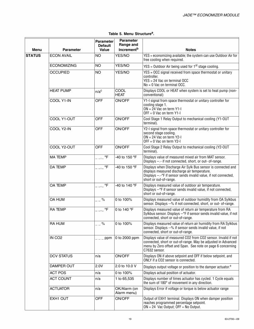
Table 5. Menu Structurea.
Menu Parameter
Parameter Default Value
Parameter Range and Incrementb Notes
STATUS ECON AVAIL NO YES/NO YES = economizing available; the system can use Outdoor Air for free cooling when required.
ECONOMIZING NO YES/NO YES = Outdoor Air being used for 1st stage cooling.
OCCUPIED NO YES/NO YES = OCC signal received from space thermostat or unitary controller.YES = 24 Vac on terminal OCCNo = 0 Vac on terminal OCC.
HEAT PUMP n/ac COOLHEAT
Displays COOL or HEAT when system is set to heat pump (non-conventional)
COOL Y1-IN OFF ON/OFF Y1-I signal from space thermostat or unitary controller for cooling stage 1. ON = 24 Vac on term Y1-IOFF = 0 Vac on term Y1-I
COOL Y1-OUT OFF ON/OFF Cool Stage 1 Relay Output to mechanical cooling (Y1-OUT terminal).
COOL Y2-IN OFF ON/OFF Y2-I signal from space thermostat or unitary controller for second stage cooling. ON = 24 Vac on term Y2-IOFF = 0 Vac on term Y2-I
COOL Y2-OUT OFF ON/OFF Cool Stage 2 Relay Output to mechanical cooling (Y2-OUT terminal).
MA TEMP _ _._ ºF -40 to 150 ºF Displays value of measured mixed air from MAT sensor. Displays --.- if not connected, short, or out- of-range.
DA TEMP _ _._ ºF -40 to 150 ºF Displays when Discharge Air Sylk Bus sensor is connected and displays measured discharge air temperature.Displays --.-°F if sensor sends invalid value, if not connected, short or out-of-range.
OA TEMP _ _._ ºF -40 to 140 ºF Displays measured value of outdoor air temperature. Displays --°F if sensor sends invalid value, if not connected, short or out-of-range.
OA HUM _ _ % 0 to 100% Displays measured value of outdoor humidity from OA Sylkbus sensor. Displays --% if not connected, short, or out- of-range.
RA TEMP _ _._ ºF 0 to 140 ºF Displays measured value of return air temperature from RA Sylkbus sensor. Displays --°F if sensor sends invalid value, if not connected, short or out-of-range.
RA HUM _ _ % 0 to 100% Displays measured value of return air humidity from RA Sylkbus sensor. Displays --% if sensor sends invalid value, if not connected, short or out-of-range.
IN CO2 _ _ _ ppm 0 to 2000 ppm Displays value of measured CO2 from CO2 sensor. Invalid if not connected, short or out-of-range. May be adjusted in Advanced menu by Zero offset and Span. See note on page 6 concerning C7632 sensor.
DCV STATUS n/a ON/OFF Displays ON if above setpoint and OFF if below setpoint, and ONLY if a CO2 sensor is connected.
DAMPER OUT 2.0V 2.0 to 10.0 V Displays output voltage or position to the damper actuator.e
ACT POS n/a 0 to 100% Displays actual position of actuator.
ACT COUNT n/a 1 to 65,535 Displays number of times actuator has cycled. 1 Cycle equals the sum of 180° of movement in any direction.
ACTUATOR n/a OK/Alarm (on Alarm menu)
Displays Error if voltage or torque is below actuator range
EXH1 OUT OFF ON/OFF Output of EXH1 terminal. Displays ON when damper positionreaches programmed percentage setpoint.ON = 24 Vac Output; OFF = No Output.

JADE™ ECONOMIZER MODULE
63-2700—09 20
STATUS CONTINUED
EXH2 OUT OFF ON/OFF Output of AUX1 O terminal Displays ON when damper position reaches programmed percentage setpointON = 24 Vac Output, OFF = No Output; displays only if AUX1 O = EXH2
ERV OFF ON/OFF Output of AUX1 O terminal, ON = 24 Vac Output, OFF = No Output; displays only if AUX1 O = ERV
MECH COOL ONorHEAT STAGES ON
0 0, 1, or 2 Displays number of mechanical cooling stages that are active.
Displays the stage of heat pump heating that is active.
FAN SPEED n/a LOW or HIGH Displays speed of fan on a 2-speed fan unit
W (HEAT IN) n/a ON/OFF Displays status of heat on a 2-speed fan unit.
SETPOINTS MAT SET 53ºF 38 to 70 ºF; increment by 1
The economizer will modulate the OA damper to maintain the mixed air temperature at the setpoint.
LOW T LOCK 32ºF -45 to 80 ºF; increment by 1
Setpoint determines outdoor temperature when the mechanical cooling cannot be turned on. Commonly referred to as the Compressor lockout. At or below the setpoint the Y1-O and Y2-O will not be energized on the controller.
DRYBLB SET 63ºF 48 to 80 ºF; increment by 1
Dry bulb setpoint will only appear if using dry bulb change over.Setpoint determines where the economizer will assume outdoor air temperature is good for free cooling; e.g.; at 63 ºF setpoint unit will economizer at 62 ºF and below and not economize at 64 ºF and above. There is a a 2 ºF deadband.
ENTH CURVE ES3 ES1, ES2, ES3, ES4, or ES5
ES curve will only appear if using enthalpy changeover.Enthalpy boundary “curves” for economizing using single enthalpy.See page 22 for description of enthalpy curves.
DCV SET 1100ppm 500 to 2000 ppmincrement by 100
Displays ONLY if a CO2 sensor is connected.Setpoint for Demand Control Ventilation of space. Above the setpoint, the OA dampers will modulate open to bring in additional OA to maintain a space ppm level below the setpoint.
MIN POS 2.8 V 2 to 10 Vdc Displays ONLY if a CO2 sensor is NOT connected.
With 2-speed fan units MIN POS L (low speed fan) and MIN POS H (high speed fan) settings are required. Default for MIN POS L is 3.2V and MIN POS H is 2.8V.
VENTMAX 2.8 V 2 to 10 Vdc Displays only if a CO2 sensor is connected.Used for Vbz (ventilation max cfm) setpoint. VENTMAX is the same setting as MIN POS would be if you did not have the CO2 sensor.
100 to 9990 cfmincrement by 10
If OA, MA RA and CO2 sensors are connected and DCV CAL ENABLE is set to AUTO mode, the OA dampers are controlled by CFM and displays from 100 to 9990 cfm.
2 to 10 Vdc With 2-speed fan units VENTMAX L (low speed fan) and VENTMAX H (high speed fan) settings are required. Default for VENTMAX L is 3.2V and VENTMAX H is 2.8V.
VENTMIN 2.25 V 2 to 10 Vdc Displays only if CO2 sensor is connected.Used for Va (ventilation min cfm) setpoint. This is the ventilation requirement for less than maximum occupancy of the space.
100 to 9990 cfmincrement by 10
If OA, MA RA and CO2 sensors are connected and DCV CAL ENABLE is set to AUTO mode, the OA dampers are controlled by CFM and displays from 100 to 9990 cfm.
2 to 10 Vdc With 2-speed fan units VENTMIN L (low speed fan) and VENTMIN H (high speed fan) settings are required. Default for VENTMIN L is 2.5V and VENTMIN H is 2.25V.
ERV OAT SPd 32ºF 0 to 50 ºF; increment by 1
Only when AUX1 O = ERV
Table 5. Menu Structurea. (Continued)
Menu Parameter
Parameter Default Value
Parameter Range and Incrementb Notes
JADE™ ECONOMIZER MODULE
21 63-2700—09
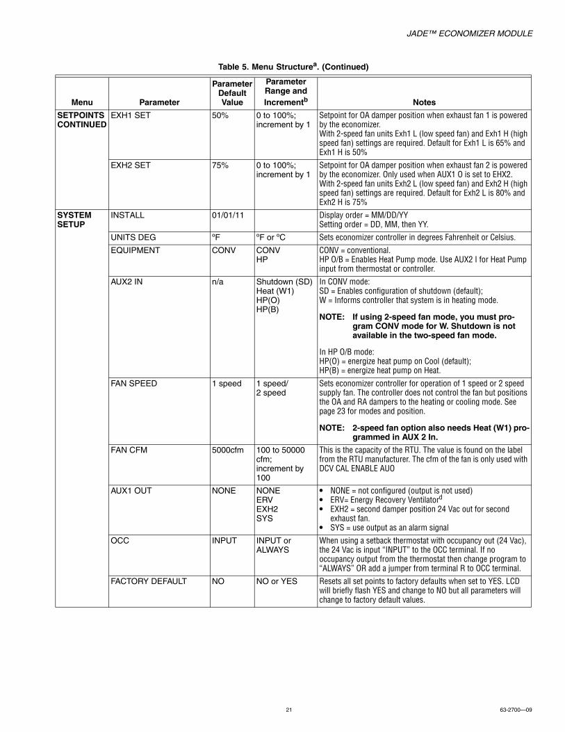
SETPOINTS CONTINUED
EXH1 SET 50% 0 to 100%; increment by 1
Setpoint for OA damper position when exhaust fan 1 is powered by the economizer.With 2-speed fan units Exh1 L (low speed fan) and Exh1 H (high speed fan) settings are required. Default for Exh1 L is 65% and Exh1 H is 50%
EXH2 SET 75% 0 to 100%; increment by 1
Setpoint for OA damper position when exhaust fan 2 is powered by the economizer. Only used when AUX1 O is set to EHX2.With 2-speed fan units Exh2 L (low speed fan) and Exh2 H (high speed fan) settings are required. Default for Exh2 L is 80% and Exh2 H is 75%
SYSTEM SETUP
INSTALL 01/01/11 Display order = MM/DD/YYSetting order = DD, MM, then YY.
UNITS DEG ºF ºF or ºC Sets economizer controller in degrees Fahrenheit or Celsius.
EQUIPMENT CONV CONVHP
CONV = conventional.HP O/B = Enables Heat Pump mode. Use AUX2 I for Heat Pump input from thermostat or controller.
AUX2 IN n/a Shutdown (SD)Heat (W1)HP(O)HP(B)
In CONV mode:SD = Enables configuration of shutdown (default);W = Informs controller that system is in heating mode.
NOTE: If using 2-speed fan mode, you must pro-gram CONV mode for W. Shutdown is not available in the two-speed fan mode.
In HP O/B mode:HP(O) = energize heat pump on Cool (default);HP(B) = energize heat pump on Heat.
FAN SPEED 1 speed 1 speed/2 speed
Sets economizer controller for operation of 1 speed or 2 speed supply fan. The controller does not control the fan but positions the OA and RA dampers to the heating or cooling mode. See page 23 for modes and position.
NOTE: 2-speed fan option also needs Heat (W1) pro-grammed in AUX 2 In.
FAN CFM 5000cfm 100 to 50000 cfm;increment by 100
This is the capacity of the RTU. The value is found on the label from the RTU manufacturer. The cfm of the fan is only used with DCV CAL ENABLE AUO
AUX1 OUT NONE NONEERVEXH2SYS
• NONE = not configured (output is not used)• ERV= Energy Recovery Ventilatord
• EXH2 = second damper position 24 Vac out for second exhaust fan.
• SYS = use output as an alarm signal
OCC INPUT INPUT or ALWAYS
When using a setback thermostat with occupancy out (24 Vac), the 24 Vac is input “INPUT” to the OCC terminal. If no occupancy output from the thermostat then change program to “ALWAYS” OR add a jumper from terminal R to OCC terminal.
FACTORY DEFAULT NO NO or YES Resets all set points to factory defaults when set to YES. LCD will briefly flash YES and change to NO but all parameters will change to factory default values.
Table 5. Menu Structurea. (Continued)
Menu Parameter
Parameter Default Value
Parameter Range and Incrementb Notes

JADE™ ECONOMIZER MODULE
63-2700—09 22
ADVANCED SETUP
MA LO SET 45 ºF 35 to 65 ºF;increment by 1º
Temp to activate Freeze Protection (close damper or modulate to MIN POS if temp falls below set value)
FREEZE POS CLO CLOMIN
Damper position when freeze protection is active (closed or MIN POS).
CO2 ZERO 0ppm 0 to 500 ppm;increment by 10
CO2 ppm level to match CO2 sensor start level.
CO2 SPAN 2000ppm 1000 to 3000 ppm;increment by 50
CO2 ppm span to match CO2 sensor; e.g.; 500-1500 sensor output would be 500 CO2 zero and 1000 CO2 span. See note on page 6 for C7632 CO2 sensor.
STG3 DLY 2.0h 0 min, 5 min, 15 min, then 15 min intervals. Up to 4h or OFF
Delay after stage 2 for cool has been active. Turns on 2nd stage of mechanical cooling when economizer is 1st stage call and mechanical cooling is 2nd stage call. Allows three stages of cooling, 1 economizer and 2 mechanical.OFF = no Stage 3 cooling.
SD DMPR POS CLO CLOOPN
Indicates shutdown signal from space thermostat or unitary controller. When controller receives 24 Vac input on the SD terminal in conventional mode, the OA damper will open if programmed for OPN and OA damper will close if programmed for CLO. All other controls, e.g., Y1-O, Y2-O, EXH1, etc. will shut off.
DA LO ALM 45 ºF NONE35ºF to 65ºF in 5ºF increments
Used for alarm for when the DA air temperature is too low. Set lower range of alarm, below this temperature the alarm will show on the display.
DA HI ALM 80 ºF NONE70 ºF to 180 ºF in 5º F increments
Used for alarm for when the DA air temperature is too high. Set high range of alarm, above this temperature the alarm will show on the display
DCVCAL ENA MAN MAN (manual)AUTO
Turns on the DCV automatic control of the dampers. Resets ventilation based on the RA, OA and MA sensor conditions. Requires all sensors (RA, OA, MA and CO2). This operation is not operable with a 2-speed fan unit.
MAT T CAL 0.0 F° +/-2.5F° Allows for the operator to adjust for an out of calibration temperature sensor
OAS T CAL 0.0F° +/-2.5F° Allows for the operator to adjust for an out of calibration temperature sensor
OAS H CAL 0% RH +/-10% RH Allows for the operator to adjust for an out of calibration humidity sensor
RA T CAL 0.0F° +/-2.5F° Allows for the operator to adjust for an out of calibration temperature sensor
RA H CAL 0% RH +/-10% RH Allows for the operator to adjust for an out of calibration humidity sensor
DA T CAL 0.0 F° +/-2.5F° Allows for the operator to adjust for an out of calibration temperature sensor
2SP FAN DELAY 5 Minutes 0 to 20 minutes in 1 minute increments.
When in economizing mode this is the delay for the high speed fan to try to satisfy the call for second stage cooling before the first stage mechanical cooling is enabled.
Table 5. Menu Structurea. (Continued)
Menu Parameter
Parameter Default Value
Parameter Range and Incrementb Notes

JADE™ ECONOMIZER MODULE
23 63-2700—09
CHECKOUTf DAMPER MINIMUM POSITION
n/a n/a The checkout for the damper minimum positions is based on the system. See Table 6.
DAMPER OPEN n/a n/a Positions damper to the full open position.Exhaust fan contacts enable during the DAMPER OPEN test. Make sure you pause in this mode to allow for exhaust contacts to energize due to the delay in the system.
DAMPER CLOSE n/a n/a Positions damper to the fully closed position.
CONNECT Y1-O n/a n/a Closes the Y1-O relay (Y1-O).See CAUTION on page 31
CONNECT Y2-O n/a n/a Closes the Y2-O relay (Y2-O).See CAUTION on page 31
CONNECT AUX1-O n/a n/a Energizes the AUX1-O output. If AUX1-O setting is:• NONE – no action taken• ERV – 24 Vac out. Turns on or signals an ERV that the
conditions are not good for economizing but are good for ERV operation.d
• SYS – 24 Vac out. Issues a system alarm.
CONNECT EXH1 n/a n/a Closes the power exhaust fan 1 relay (EXH1)
ALARMS(#) Alarms display only when they are active. The menu title “ALARMS (#)” includes the number of active alarms in parenthesis (). When using SYLK bus sensors, "SYLK" will appear on the screen, and when using 20k OA temperature sensors, "SENS T" will appear on the screen.
MA T SENS ERR n/a n/a Mixed air sensor has failed or become disconnected - check wiring then replace sensor if the alarm continues
CO2 SENS ERR n/a n/a CO2 sensor has failed, gone out of range or become disconnected - check wiring then replace sensor if the alarm continues
OA SYLK T ERR n/a n/a Outdoor air enthalpy sensor has failed or become disconnected - check wiring then replace sensor if the alarm continuesOA SYLK H ERR n/a n/a
RA SYLK T ERR n/a n/a Return air enthalpy sensor has failed or become disconnected - check wiring then replace sensor if the alarm continuesRA SYLK H ERR n/a n/a
DA SYLK T ERR n/a n/a Discharge air sensor has failed or become disconnected - check wiring then replace sensor if the alarm continues
OA SENS T ERR n/a n/a Outdoor air temperature sensor has failed or become disconnected - check wiring then replace sensor if the alarm continues
ACT ERROR n/a n/a Actuator has failed or become disconnected - check for stall, over voltage, under voltage and actuator count. Replace actuator if damper is moveable and supply voltage is between 21.6 V and 26.4 V. Check actuator count on STATUS menu.
FREEZE ALARM n/a n/a Check if outdoor temperature is below the LOW Temp Lockout on setpoint menu. Check if Mixed air temperature on STATUS menu is below the Lo Setpoint on Advanced setup menu. When conditions are back in normal range then the alarm will go away.
SHUTDOWN ACTIVE n/a n/a AUX2 IN is programmed for SHUTDOWN and 24 V has been applied to AUX 2IN terminal
DMP CAL RUNNING n/a n/a If DCV Auto enable has been programmed, when the Jade is completing a calibration on the dampers, this alarm will display. Wait until the calibration is completed and the alarm will go away. Must have OA, MA and RA sensors for DCV calibration; set up is in the Advanced setup menu
DA SENS ALM n/a n/a Discharge air temperature is out of the range set in the ADVANCED SETUP Menu. Check the temperature of the discharge air.
Table 5. Menu Structurea. (Continued)
Menu Parameter
Parameter Default Value
Parameter Range and Incrementb Notes

JADE™ ECONOMIZER MODULE
63-2700—09 24
Table 6. Damper minimum position settings and readings on checkout menu.
ALARMS(#)CONTINUED
SYS ALARM n/a n/a When AUX1-O is set to SYS and there is any alarm (e.g., failed sensors, etc.), the AUX1-O terminal has 24 Vac out.
ACT UNDER V n/a n/a Voltage received by Actuator is above expected range
ACT OVER V n/a n/a Voltage received by Actuator is below expected range
ACT STALLED n/a n/a Actuator stopped before achieving commanded position
FEATURES ADJUSTABLE ONLY BY USE OF THE W7220 PC MOD TOOL
ACT STALL ALARM SUPPRESSION
Disabled Enabled or Disabled
If enabled this feature allows the operator to suppress the stall alarm in a specific range of the actuator stroke.
FACTORY DEFAULTS n/a n/a Allows the operator to hide the factory default menu item using the PC Tool.
a Table 5 illustrates the complete hierarchy. Your menu parameters may be different depending on your configuration. For example if you do not have a DCV (CO2) sensor, then none of the DCV parameters appear.
b When values are displayed, pressing and holding the or button causes the display to automatically increment.c n/a = not applicabled ERV Operation: When in Cooling mode AND the conditions are NOT OK for economizing - the ERV terminal will be energized. In
the Heating mode the ERV terminal will be energized when the OA is below the ERV OAT setpoint in the setpoint menu. e When used with Honeywell communicating actuator the damper out is reported in XX.X% open versus XX.X Vdc.f After 10 minutes without a command or mode change, the controller will change to normal operation.
Fan SpeedDemand Control Ventilation
(CO2 Sensor) Setpoints Checkout
1 NO MIN POS VMAX-HS
1 NO N/A N/A
2 NO MIN POS H VMAX-HS
2 NO MIN POS L VMAX-LS
1 YES VENT MIN VMIN-HS
1 YES VENT MAX VMAX-HS
2 YES VENT MIN H VMIN-HS
2 YES VENT MAX H VMAX-LS
2 YES VENT MINL N/A
2 YES VENT MAX L N/A
Table 5. Menu Structurea. (Continued)
Menu Parameter
Parameter Default Value
Parameter Range and Incrementb Notes
JADE™ ECONOMIZER MODULE
25 63-2700—09
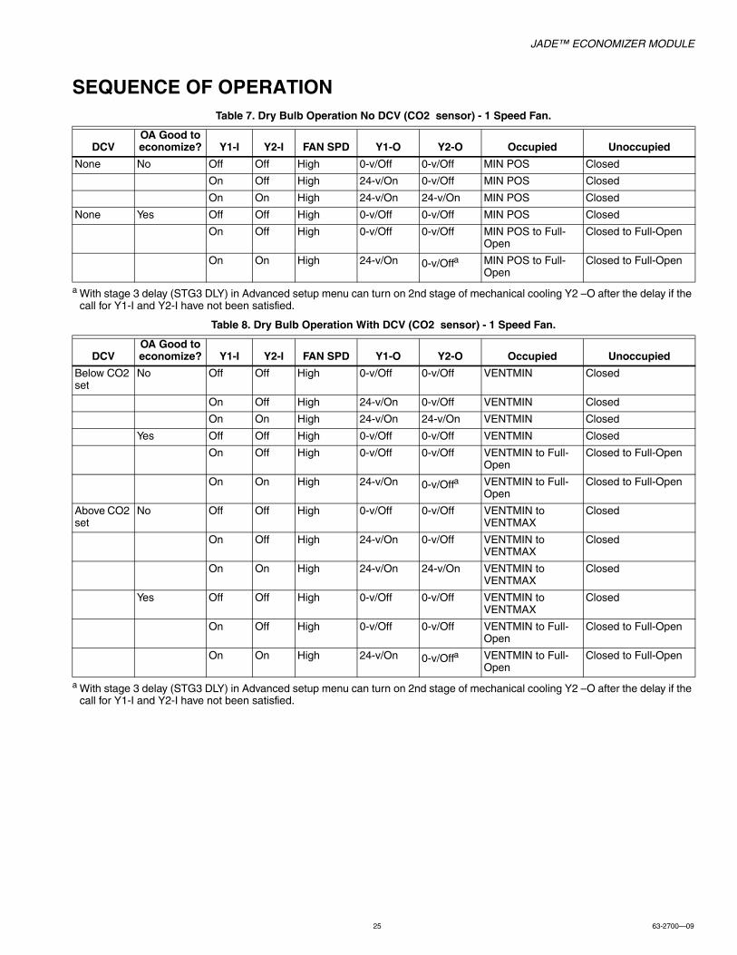
SEQUENCE OF OPERATIONTable 7. Dry Bulb Operation No DCV (CO2 sensor) - 1 Speed Fan.
a With stage 3 delay (STG3 DLY) in Advanced setup menu can turn on 2nd stage of mechanical cooling Y2 –O after the delay if the call for Y1-I and Y2-I have not been satisfied.
Table 8. Dry Bulb Operation With DCV (CO2 sensor) - 1 Speed Fan.
a With stage 3 delay (STG3 DLY) in Advanced setup menu can turn on 2nd stage of mechanical cooling Y2 –O after the delay if the call for Y1-I and Y2-I have not been satisfied.
DCVOA Good to economize? Y1-I Y2-I FAN SPD Y1-O Y2-O Occupied Unoccupied
None No Off Off High 0-v/Off 0-v/Off MIN POS Closed
On Off High 24-v/On 0-v/Off MIN POS Closed
On On High 24-v/On 24-v/On MIN POS Closed
None Yes Off Off High 0-v/Off 0-v/Off MIN POS Closed
On Off High 0-v/Off 0-v/Off MIN POS to Full-Open
Closed to Full-Open
On On High 24-v/On 0-v/Offa MIN POS to Full-Open
Closed to Full-Open
DCVOA Good to economize? Y1-I Y2-I FAN SPD Y1-O Y2-O Occupied Unoccupied
Below CO2 set
No Off Off High 0-v/Off 0-v/Off VENTMIN Closed
On Off High 24-v/On 0-v/Off VENTMIN Closed
On On High 24-v/On 24-v/On VENTMIN Closed
Yes Off Off High 0-v/Off 0-v/Off VENTMIN Closed
On Off High 0-v/Off 0-v/Off VENTMIN to Full-Open
Closed to Full-Open
On On High 24-v/On 0-v/Offa VENTMIN to Full-Open
Closed to Full-Open
Above CO2 set
No Off Off High 0-v/Off 0-v/Off VENTMIN to VENTMAX
Closed
On Off High 24-v/On 0-v/Off VENTMIN to VENTMAX
Closed
On On High 24-v/On 24-v/On VENTMIN to VENTMAX
Closed
Yes Off Off High 0-v/Off 0-v/Off VENTMIN to VENTMAX
Closed
On Off High 0-v/Off 0-v/Off VENTMIN to Full-Open
Closed to Full-Open
On On High 24-v/On 0-v/Offa VENTMIN to Full-Open
Closed to Full-Open
JADE™ ECONOMIZER MODULE
63-2700—09 26
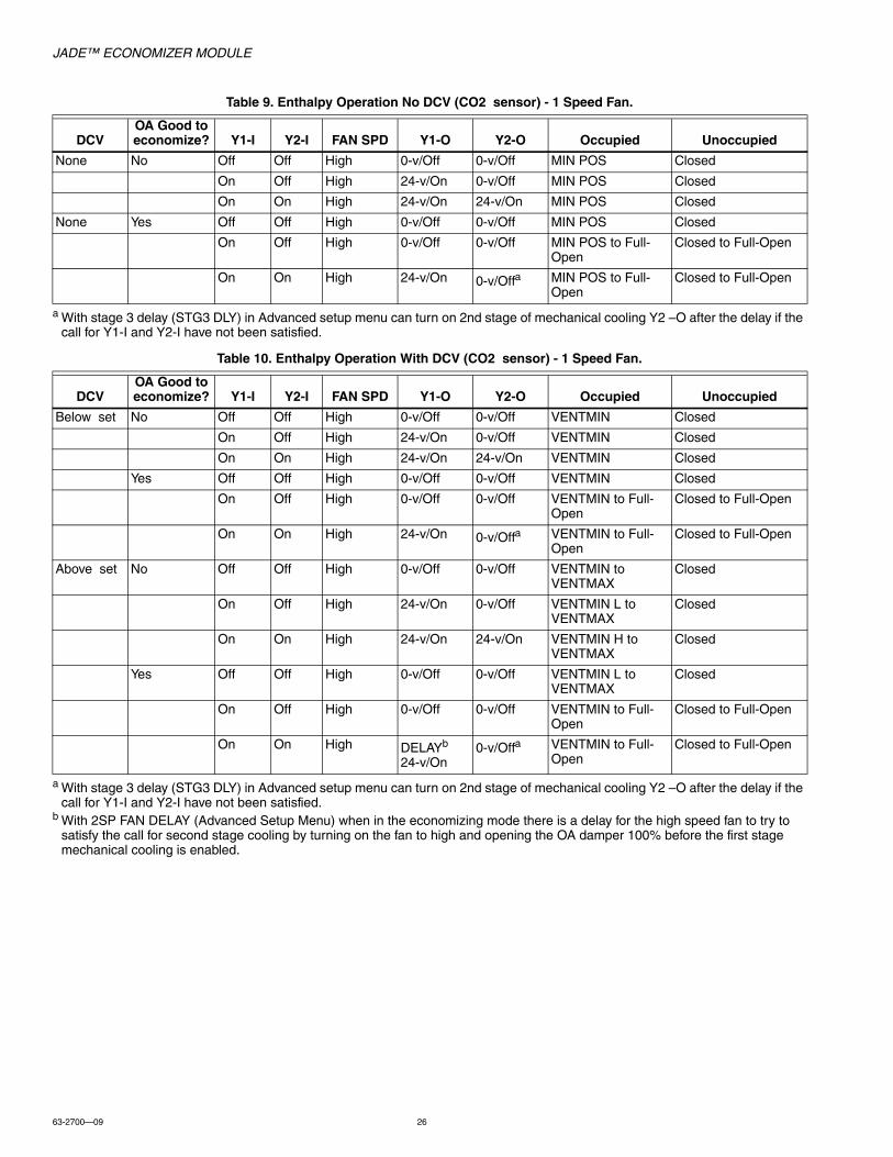
Table 9. Enthalpy Operation No DCV (CO2 sensor) - 1 Speed Fan.
a With stage 3 delay (STG3 DLY) in Advanced setup menu can turn on 2nd stage of mechanical cooling Y2 –O after the delay if the call for Y1-I and Y2-I have not been satisfied.
Table 10. Enthalpy Operation With DCV (CO2 sensor) - 1 Speed Fan.
a With stage 3 delay (STG3 DLY) in Advanced setup menu can turn on 2nd stage of mechanical cooling Y2 –O after the delay if the call for Y1-I and Y2-I have not been satisfied.
b With 2SP FAN DELAY (Advanced Setup Menu) when in the economizing mode there is a delay for the high speed fan to try to satisfy the call for second stage cooling by turning on the fan to high and opening the OA damper 100% before the first stage mechanical cooling is enabled.
DCVOA Good to economize? Y1-I Y2-I FAN SPD Y1-O Y2-O Occupied Unoccupied
None No Off Off High 0-v/Off 0-v/Off MIN POS Closed
On Off High 24-v/On 0-v/Off MIN POS Closed
On On High 24-v/On 24-v/On MIN POS Closed
None Yes Off Off High 0-v/Off 0-v/Off MIN POS Closed
On Off High 0-v/Off 0-v/Off MIN POS to Full-Open
Closed to Full-Open
On On High 24-v/On 0-v/Offa MIN POS to Full-Open
Closed to Full-Open
DCVOA Good to economize? Y1-I Y2-I FAN SPD Y1-O Y2-O Occupied Unoccupied
Below set No Off Off High 0-v/Off 0-v/Off VENTMIN Closed
On Off High 24-v/On 0-v/Off VENTMIN Closed
On On High 24-v/On 24-v/On VENTMIN Closed
Yes Off Off High 0-v/Off 0-v/Off VENTMIN Closed
On Off High 0-v/Off 0-v/Off VENTMIN to Full-Open
Closed to Full-Open
On On High 24-v/On 0-v/Offa VENTMIN to Full-Open
Closed to Full-Open
Above set No Off Off High 0-v/Off 0-v/Off VENTMIN to VENTMAX
Closed
On Off High 24-v/On 0-v/Off VENTMIN L to VENTMAX
Closed
On On High 24-v/On 24-v/On VENTMIN H to VENTMAX
Closed
Yes Off Off High 0-v/Off 0-v/Off VENTMIN L to VENTMAX
Closed
On Off High 0-v/Off 0-v/Off VENTMIN to Full-Open
Closed to Full-Open
On On High DELAYb
24-v/On0-v/Offa VENTMIN to Full-
OpenClosed to Full-Open

JADE™ ECONOMIZER MODULE
27 63-2700—09
Table 11. Dry Bulb Operation No DCV (CO2 sensor) - 2 Speed Fan.
aWith stage 3 delay (STG3 DLY) in Advanced setup menu can turn on 2nd stage of mechanical cooling Y2 –O after the delay if the call for Y1-I and Y2-I have not been satisfied.
b With 2SP FAN DELAY (Advanced Setup Menu) when in the economizing mode there is a delay for the high speed fan to try to satisfy the call for second stage cooling by turning on the fan to high and opening the OA damper 100% before the first stage mechanical cooling is enabled.
Table 12. Dry Bulb Operation With DCV (CO2 sensor) - 2 Speed Fan.
aWith stage 3 delay (STG3 DLY) in Advanced setup menu can turn on 2nd stage of mechanical cooling Y2 –O after the delay if the call for Y1-I and Y2-I have not been satisfied.
b With 2SP FAN DELAY (Advanced Setup Menu) when in the economizing mode there is a delay for the high speed fan to try to satisfy the call for second stage cooling by turning on the fan to high and opening the OA damper 100% before the first stage mechanical cooling is enabled.
Table 13. Enthalpy Operation No DCV (CO2 sensor) - 2 Speed Fan.
DCVOA Good to economize? Y1-I Y2-I FAN SPD Y1-O Y2-O Occupied Unoccupied
None No Off Off Low 0-v/Off 0-v/Off MIN POS L Closed
On Off Low 24-v/On 0-v/Off MIN POS L Closed
On On High 24-v/On 24-v/On MIN POS H Closed
None Yes Off Off Low 0-v/Off 0-v/Off MIN POS L Closed
On Off Low 0-v/Off 0-v/Off MIN POS L to Full-Open
Closed to Full-Open
On On High DELAYb
24-v/On0-v/Offa MIN POS H to Full-
OpenClosed to Full-Open
DCVOA Good to economize? Y1-I Y2-I FAN SPD Y1-O Y2-O Occupied Unoccupied
Below set No Off Off Low 0-v/Off 0-v/Off VENTMIN L Closed
On Off Low 24-v/On 0-v/Off VENTMIN L Closed
On On High 24-v/On 24-v/On VENTMIN H Closed
Yes Off Off Low 0-v/Off 0-v/Off VENTMIN L Closed
On Off Low 0-v/Off 0-v/Off VENTMIN L to Full-Open
Closed to Full-Open
On On High 24-v/On 0-v/Offa VENTMIN H to Full-Open
Closed to Full-Open
Above set No Off Off Low 0-v/Off 0-v/Off VENTMIN L to VENTMAX
Closed
On Off Low 24-v/On 0-v/Off VENTMIN L to VENTMAX
Closed
On On High 24-v/On 24-v/On VENTMIN H to VENTMAX
Closed
Yes Off Off Low 0-v/Off 0-v/Off VENTMIN L to VENTMAX
Closed
On Off Low 0-v/Off 0-v/Off VENTMIN L to Full-Open
Closed to Full-Open
On On High DELAYb
24-v/On0-v/Offa VENTMIN H to Full-
OpenClosed to Full-Open
DCVOA Good to economize? Y1-I Y2-I FAN SPD Y1-O Y2-O Occupied Unoccupied
NO CO2 SENSOR
No Off Off Low 0-v/Off 0-v/Off MIN POS L Closed
On Off Low 24-v/On 0-v/Off MIN POS L Closed

JADE™ ECONOMIZER MODULE
63-2700—09 28
aWith stage 3 delay (STG3 DLY) in Advanced setup menu can turn on 2nd stage of mechanical cooling Y2 –O after the delay if the call for Y1-I and Y2-I have not been satisfied.
b With 2SP FAN DELAY (Advanced Setup Menu) when in the economizing mode there is a delay for the high speed fan to try to satisfy the call for second stage cooling by turning on the fan to high and opening the OA damper 100% before the first stage mechanical cooling is enabled.
On On High 24-v/On 24-v/On MIN POS H Closed
Yes Off Off Low 0-v/Off 0-v/Off MIN POS L Closed
On Off Low 0-v/Off 0-v/Off MIN POS L to Full-Open
Closed to Full-Open
On On High DELAYb
24-v/On0-v/Offa MIN POS H to Full-
OpenClosed to Full-Open
DCVOA Good to economize? Y1-I Y2-I FAN SPD Y1-O Y2-O Occupied Unoccupied

JADE™ ECONOMIZER MODULE
29 63-2700—09
Table 14. Enthalpy Operation With DCV (CO2 sensor) - 2 Speed Fan.
aWith stage 3 delay (STG3 DLY) in Advanced setup menu can turn on 2nd stage of mechanical cooling Y2 –O after the delay if the call for Y1-I and Y2-I have not been satisfied.
b With 2SP FAN DELAY (Advanced Setup Menu) when in the economizing mode there is a delay for the high speed fan to try to satisfy the call for second stage cooling by turning on the fan to high and opening the OA damper 100% before the first stage mechanical cooling is enabled.
Fig. 22. Single Enthalpy curve and boundaries.
DCVOA Good to economize? Y1-I Y2-I FAN SPD Y1-O Y2-O Occupied Unoccupied
Below set No Off Off Low 0-v/Off 0-v/Off VENTMIN L Closed
On Off Low 24-v/On 0-v/Off VENTMIN L Closed
On On High 24-v/On 24-v/On VENTMIN H Closed
Yes Off Off Low 0-v/Off 0-v/Off VENTMIN L Closed
On Off Low 0-v/Off 0-v/Off VENTMIN L to Full-Open
Closed to Full-Open
On On High 24-v/On 0-v/Offa VENTMIN H to Full-Open
Closed to Full-Open
Above set No Off Off Low 0-v/Off 0-v/Off VENTMIN L to VENTMAX
Closed
On Off Low 24-v/On 0-v/Off VENTMIN L to VENTMAX
Closed
On On High 24-v/On 24-v/On VENTMIN H to VENTMAX
Closed
Yes Off Off Low 0-v/Off 0-v/Off VENTMIN L to VENTMAX
Closed
On Off Low 0-v/Off 0-v/Off VENTMIN L to Full-Open
Closed to Full-Open
On On High DELAYb
24-v/On0-v/Offa VENTMIN H to Full-
OpenClosed to Full-Open
Table 15. Single Enthalpy and Dual Enthalpy High Limit Curves.
Enthalpy Curve
Temp.Dry-Bulb (°F)
Temp.Dewpoint (°F)
Enthalpy(btu/lb/da)
Point P1 Point P2
Temp. °F Humidity %RH Temp. °F Humidity %RH
ES1 80.0 60.0 28.0 80.0 36.8 66.3 80.1
ES2 75.0 57.0 26.0 75.0 39.6 63.3 80.0
ES3 70.0 54.0 24.0 70.0 42.3 59.7 81.4
ES4 65.0 51.0 22.0 65.0 44.8 55.7 84.2
ES5 60.0 48.0 20.0 60.0 46.9 51.3 88.5
HL 86.0 66.0 32.4 86.0 38.9 72.4 80.3
ECONOMIXING
AVAILABLE
NOT AVAILABLE
TEMPERATURE
AB
SO
LUT
E H
UM
IDIT
Y
RA
TE
MP
RA HUM (%RH)ENTHALPY
ES4 ES3 ES2 ES1 HL
P2 (T,RH)
DUAL ENTHALPY HIGH LIMIT
SINGLE ENTHALPY
ES5
P1(T,RH)
M32286A

JADE™ ECONOMIZER MODULE
63-2700—09 30
Enthalpy SettingsWhen the OA temperature, enthalpy and dew point are below the respective setpoints, the Outdoor Air can be used for economizing. Fig. 22 shows the new single enthalpy boundaries in the W7220. There are 5 boundaries (setpoints ES1 through ES5), which are defined by dry bulb temperature, enthalpy and dew point.
Refer to Table 15 for the ENTH CURVE setpoint values.
To use enthalpy the W7220 must have a C7400S Sylkbus sensor for OA. The W7220 calculates the enthalpy and dew point using the OA temperature and humidity input from the OA sensor. When the OA temperature, OA humidity and OA dew point are all below the selected boundary, the economizer sets the economizing mode to YES, economizing is available.
When conditions are above the selected boundary, the conditions are not good to economize and the mode is set to NO.
Fig. 22 shows the 5 current boundaries. There is also a high limit boundary for differential enthalpy. The high limit boundary is ES1 when there are no stages of mechanical cooling energized and HL when a compressor stage is energized.
Table 15 provides the values for each boundary limit.
Two-Speed Fan OperationThe later versions of the W7220 Jade controller have the capability to work with a system using a 2-speed supply fan. The W7220 does not control the supply directly but uses the following input status to determine the speed of the supply fan and controls the OA damper to the required position.
The W (heating mode) is not controlled by the W7220 but it requires the status to know where to position the OA damper for minimum position for the fan speed.
The 2 speed fan delay is available when the system is programmed for 2 speed fan (in the System Setup menu item). The 2 speed fan delay is defaulted to 5 minutes and can be changed in the Advanced Setup menu item. When the unit has a call for Y1 In and in the free cooling mode and there is a call for Y2 In, the 2-speed fan delay starts and the OA damper will modulate 100% open, the supply fan should be set to high speed by the unit controller. After the delay one of two actions will happen:
• The Y2 In call will be satisfied with the damper 100% open and fan on high speed and the call will turn off
OR• If the call for additional cooling in the space has not been
satisfied then the first stage of mechanical cooling will be enabled through Y1 Out or Y2 Out.
State Fan Speed
OCC Low
Y1 Low
Y2 High
W High
JADE™ ECONOMIZER MODULE
31 63-2700—09
CHECKOUTInspect all wiring connections at the Economizer module’s terminals, and verify compliance with the installation wiring diagrams.
For checkout, review the Status of each configured parameter and perform the Checkout tests.
NOTE: See “Interface Overview” on page 18. for information about menu navigation and use of the keypad.
WARNINGElectrical Shock Hazard.Can cause severe injury, death or property damage.Disconnect power supply before beginning wiring or making wiring connections, to prevent electrical shock or equipment damage.If any wiring changes are required, first be sure to remove power from the Economizer module before starting work. Pay particular attention to verifying the power connection (24 Vac).
Power UpAfter the module is mounted and wired, apply power.
Initial Menu DisplayOn initial start up, Honeywell displays on the first line and Economizer W7220 on the second line. After a brief pause, the revision of the software appears on the first line and the second line will be blank.
Power Loss (Outage or Brownout)All setpoints and advanced settings are restoreda after any power loss or interruption.
a All settings are stored in non-volatile flash memory.
StatusUse the Status menu (see Table 5) to check the parameter values for the various devices and sensors configured.
NOTE: See “Interface Overview” on page 18. for information about menu navigation and use of the keypad.
Checkout TestsUse the Checkout menu (Table 5) to test the damper operation and any configured outputs. Only items that are configured are shown in the Checkout menu.
NOTE: See “Interface Overview” on page 18. for information about menu navigation and use of the keypad.
To perform a Checkout test:1. Scroll to the desired test in the Checkout menu using the
and buttons.2. Press the button to select the item.3. RUN? appears on the display.4. Press the button to start the test.5. The unit pauses and then displays IN PROGRESS.6. When all parameters have been tested, press the
button (Menu up) to end the test (e.g. turn off the relay).The checkout tests can all be performed at the time of installation or any time during the operation of the system as a test that the system is operable.
CAUTIONEquipment damage may result.Be sure to allow enough time for compressor startup and shutdown between checkout tests so that you do not short-cycle the compressors.

JADE™ ECONOMIZER MODULE
Automation and Control SolutionsHoneywell International Inc.
1985 Douglas Drive North
Golden Valley, MN 55422
customer.honeywell.com
® U.S. Registered Trademark© 2014 Honeywell International Inc.63-2700—09 M.S. Rev. 03-14 Printed in United States
TROUBLESHOOTING
AlarmsThe Economizer module provides alarm messages that display on the 2-line LCD.
NOTE: Upon power up, the module waits 60 minutes before checking for alarms. This allows time for all the configured devices (e.g. sensors, actuator) to become operational. The exception is the MA sensor which will alarm immediately.
If one or more alarms are present and there has been no keypad activity for at least 5 minutes, the Alarms menu displays and cycles through the active alarms.
You can also navigate to the Alarms menu at any time.
Clearing AlarmsOnce the alarm has been identified and the cause has been removed (e.g. replaced faulty sensor), the alarm can be cleared from the display.
To clear an alarm, perform the following:1. Navigate to the desired alarm.2. Press the button.3. ERASE? displays.4. Press the button.5. ALARM ERASED displays.
6. Press the button (MenuUp/Exit) to complete the action and return to the previous menu.
NOTE: If an the alarm still exists after you clear it, it re-displays within 5 seconds.
By using this Honeywell literature, you agree that Honeywell will have no liability for any damages arising out of your use or modification to, the literature. You will defend and indemnify Honeywell, its affiliates and subsidiaries, from and against any liability, cost, or damages, including attorneys’ fees, arising out of, or resulting from, any modification to the literature by you.