Embed Size (px)
Citation preview
8/12/2019 Asus P5QL-EM Manual
http://slidepdf.com/reader/full/asus-p5ql-em-manual 1/112
M o
t h
e r b o a r d
P5QL-EM
8/12/2019 Asus P5QL-EM Manual
http://slidepdf.com/reader/full/asus-p5ql-em-manual 2/112
ii
Copyright © 2008 ASUSTeK COMPUTER INC. All Rights Reserved.
No part of this manual, including the products and software described in it, may be reproduced,transmitted, transcribed, stored in a retrieval system, or translated into any language in any form or by anymeans, except documentation kept by the purchaser for backup purposes, without the express writtenpermission of ASUSTeK COMPUTER INC. (“ASUS”).
Product warranty or service will not be extended if: (1) the product is repaired, modied or altered, unless
such repair, modication of alteration is authorized in writing by ASUS; or (2) the serial number of theproduct is defaced or missing.
ASUS PROVIDES THIS MANUAL “AS IS” WITHOUT WARRANTY OF ANY KIND, EITHER EXPRESSOR IMPLIED, INCLUDING BUT NOT LIMITED TO THE IMPLIED WARRANTIES OR CONDITIONS OFMERCHANTABILITY OR FITNESS FOR A PARTICULAR PURPOSE. IN NO EVENT SHALL ASUS, ITSDIRECTORS, OFFICERS, EMPLOYEES OR AGENTS BE LIABLE FOR ANY INDIRECT, SPECIAL,INCIDENTAL, OR CONSEQUENTIAL DAMAGES (INCLUDING DAMAGES FOR LOSS OF PROFITS,LOSS OF BUSINESS, LOSS OF USE OR DATA, INTERRUPTION OF BUSINESS AND THE LIKE),EVEN IF ASUS HAS BEEN ADVISED OF THE POSSIBILITY OF SUCH DAMAGES ARISING FROM ANYDEFECT OR ERROR IN THIS MANUAL OR PRODUCT.
SPECIFICATIONS AND INFORMATION CONTAINED IN THIS MANUAL ARE FURNISHED FORINFORMATIONAL USE ONLY, AND ARE SUBJECT TO CHANGE AT ANY TIME WITHOUT NOTICE,
AND SHOULD NOT BE CONSTRUED AS A COMMITMENT BY ASUS. ASUS ASSUMES NORESPONSIBILITY OR LIABILITY FOR ANY ERRORS OR INACCURACIES THAT MAY APPEAR IN THISMANUAL, INCLUDING THE PRODUCTS AND SOFTWARE DESCRIBED IN IT.
Products and corporate names appearing in this manual may or may not be registered trademarks orcopyrights of their respective companies, and are used only for identication or explanation and to theowners’ benet, without intent to infringe.
E4165
Second Edition V2
August 2008
8/12/2019 Asus P5QL-EM Manual
http://slidepdf.com/reader/full/asus-p5ql-em-manual 3/112
iii
Contents
Notices ......................................................................................................... vi
Safety information ..................................................................................... vii
About this guide ....................................................................................... viii
P5QL-EM specications summary ............................................................. x
Chapter 1 Product introduction
1.1 Welcome! ...................................................................................... 1-2
1.2 Package contents......................................................................... 1-2
1.3 Special features............................................................................ 1-2
1.3.1 Product highlights ........................................................... 1-2
1.3.2 ASUS Special features ................................................... 1-41.4 Before you proceed ..................................................................... 1-6
1.5 Motherboard overview ................................................................. 1-7
1.5.1 Placement direction ........................................................ 1-7
1.5.2 Screw holes .................................................................... 1-7
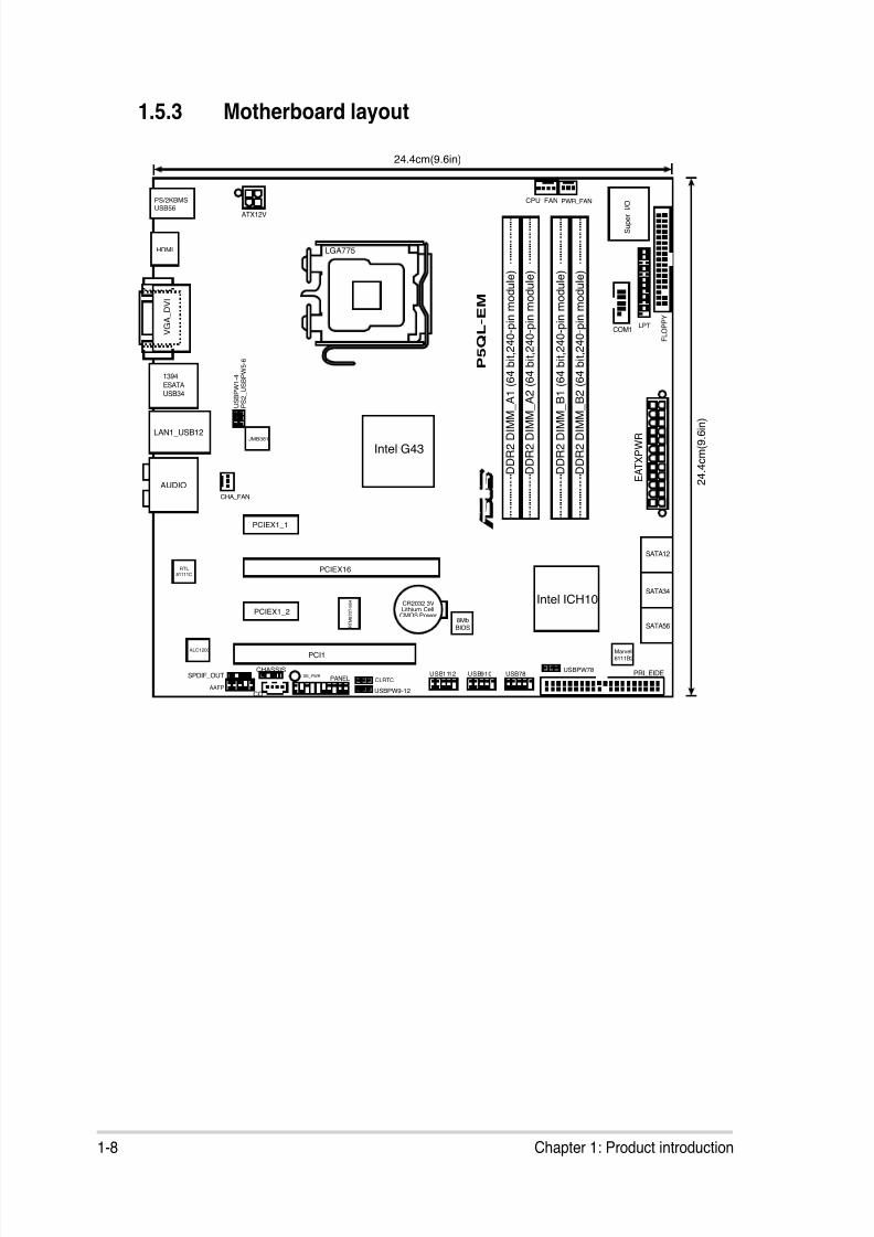
1.5.3 Motherboard layout ......................................................... 1-8
1.6 Central Processing Unit (CPU) ................................................... 1-9
1.6.1 Installling the CPU .......................................................... 1-9
1.6.2 Installling the CPU heatsink and fan ............................. 1-12
1.6.3 Uninstalling the CPU heatsink and fan ......................... 1-14
1.7 System memory ......................................................................... 1-15
1.7.1 Overview ....................................................................... 1-15
1.7.2 Memory congurations .................................................. 1-16
1.7.3 DDR2 Qualied Vendors List ........................................ 1-17
1.7.4 Installing a DIMM .......................................................... 1-21
1.7.5 Removing a DIMM ........................................................ 1-21
1.8 Expansion slots.......................................................................... 1-22
1.8.1 Installing an expansion card ......................................... 1-22
1.8.2 Conguring an expansion card ..................................... 1-22
1.8.3 Interrupt assignments ................................................... 1-23
1.8.4 PCI slot .........................................................................1-25
1.8.5 PCI Express x1 slot ....................................................... 1-25
1.8.6 PCI Express x16 Slot ................................................... 1-25
1.9 Jumpers ...................................................................................... 1-26
1.10 Connectors ................................................................................. 1-28
8/12/2019 Asus P5QL-EM Manual
http://slidepdf.com/reader/full/asus-p5ql-em-manual 4/112
iv
Contents
1.10.1 Rear panel connectors ..................................................1-28
1.10.2 Internal connectors ....................................................... 1-31
Chapter 2 BIOS setup2.1 Managing and updating your BIOS ............................................ 2-2
2.1.1 Creating a bootable oppy disk .......................................2-2
2.1.2 ASUS EZ Flash 2 utility ...................................................2-4
2.1.3 AFUDOS utility ................................................................2-5
2.1.4 ASUS CrashFree BIOS 3 utility ...................................... 2-7
2.1.5 ASUS Update utility ........................................................ 2-9
2.2 BIOS setup program .................................................................. 2-122.2.1 BIOS menu screen ........................................................2-13
2.2.2 Menu bar .......................................................................2-13
2.2.3 Navigation keys .............................................................2-13
2.2.4 Menu items ...................................................................2-14
2.2.5 Sub-menu items ............................................................2-14
2.2.6 Conguration elds .......................................................2-14
2.2.7 Pop-up window ............................................................. 2-14
2.2.8 Scroll bar .......................................................................2-14
2.2.9 General help .................................................................2-14
2.3 Main menu .................................................................................. 2-15
2.3.1 System Time ................................................................ 2-15
2.3.2 System Date ................................................................. 2-15
2.3.3 Legacy Diskette A ......................................................... 2-15
2.3.4 SATA 1~6 ......................................................................2-16
2.3.5 Storage Conguration ...................................................2-17
2.3.6 System Information .......................................................2-18
2.4 Advanced menu ......................................................................... 2-19
2.4.1 JumperFree Conguration ............................................ 2-19
2.4.2 CPU Conguration ........................................................2-22
2.4.3 Chipset ..........................................................................2-24
2.4.4 Onboard Devices Conguration ....................................2-27
2.4.5 USB Conguration ........................................................2-28
2.4.6 PCI PnP ........................................................................2-29
8/12/2019 Asus P5QL-EM Manual
http://slidepdf.com/reader/full/asus-p5ql-em-manual 5/112
v
Contents
2.5 Power menu ................................................................................ 2-30
2.5.1 Suspend Mode ..............................................................2-30
2.5.2 ACPI 2.0 Support ..........................................................2-31
2.5.3 ACPI APIC Support .......................................................2-31
2.5.4 APM Conguration ........................................................2-31
2.5.5 Hardware Monitor ......................................................... 2-33
2.6 Boot menu .................................................................................. 2-34
2.6.1 Boot Device Priority ...................................................... 2-34
2.6.2 Boot Settings Conguration .......................................... 2-35
2.6.3 Security .........................................................................2-36
2.7 Tools menu ................................................................................. 2-38
2.7.1 ASUS EZ Flash 2 ..........................................................2-38
2.7.2 Express Gate ................................................................2-39
2.7.3 AI NET 2........................................................................ 2-39
2.8 Exit menu .................................................................................... 2-40
Chapter 3 Software support
3.1 Installing an operating system ................................................... 3-2
3.2 Support DVD information ............................................................ 3-2
3.2.1 Running the support DVD ............................................... 3-2
3.2.2 Drivers menu ................................................................... 3-3
3.2.3 Utilities menu .................................................................. 3-4
3.2.4 Manual menu .................................................................. 3-6
3.2.5 ASUS Contact information .............................................. 3-7
3.2.6 Other information ............................................................ 3-7
3.3 ASUS Express Gate ..................................................................... 3-9
Appendix CPU features
A.1 Enhanced Intel SpeedStep® Technology (EIST) ........................A-2
A.1.1 System requirements ......................................................A-2
A.1.2 Using the EIST ................................................................A-2
A.2 Intel® Hyper-Threading Technology ...........................................A-4
Using the Hyper-Threading Technology ........................................A-4
8/12/2019 Asus P5QL-EM Manual
http://slidepdf.com/reader/full/asus-p5ql-em-manual 6/112
vi
Notices
Federal Communications Commission Statement
This device complies with Part 15 of the FCC Rules. Operation is subject to the
following two conditions:• This device may not cause harmful interference, and
• This device must accept any interference received including interference thatmay cause undesired operation.
This equipment has been tested and found to comply with the limits for a
Class B digital device, pursuant to Part 15 of the FCC Rules. These limits aredesigned to provide reasonable protection against harmful interference in a
residential installation. This equipment generates, uses and can radiate radio
frequency energy and, if not installed and used in accordance with manufacturer’sinstructions, may cause harmful interference to radio communications. However,there is no guarantee that interference will not occur in a particular installation. If
this equipment does cause harmful interference to radio or television reception,
which can be determined by turning the equipment off and on, the user is
encouraged to try to correct the interference by one or more of the followingmeasures:
• Reorient or relocate the receiving antenna.
• Increase the separation between the equipment and receiver.
• Connect the equipment to an outlet on a circuit different from that to which thereceiver is connected.
• Consult the dealer or an experienced radio/TV technician for help.
Canadian Department of Communications Statement
This digital apparatus does not exceed the Class B limits for radio noise emissions
from digital apparatus set out in the Radio Interference Regulations of theCanadian Department of Communications.
This class B digital apparatus complies with Canadian ICES-003.
The use of shielded cables for connection of the monitor to the graphics card isrequired to assure compliance with FCC regulations. Changes or modicationsto this unit not expressly approved by the party responsible for compliancecould void the user’s authority to operate this equipment.

8/12/2019 Asus P5QL-EM Manual
http://slidepdf.com/reader/full/asus-p5ql-em-manual 7/112
vii
Safety information
Electrical safety
• To prevent electrical shock hazard, disconnect the power cable from the
electrical outlet before relocating the system.• When adding or removing devices to or from the system, ensure that the power
cables for the devices are unplugged before the signal cables are connected. Ifpossible, disconnect all power cables from the existing system before you add
a device.
• Before connecting or removing signal cables from the motherboard, ensure
that all power cables are unplugged.
• Seek professional assistance before using an adpater or extension cord.
These devices could interrupt the grounding circuit.
• Make sure that your power supply is set to the correct voltage in your area. If
you are not sure about the voltage of the electrical outlet you are using, contact
your local power company.
• If the power supply is broken, do not try to x it by yourself. Contact a qualiedservice technician or your retailer.
Operation safety
• Before installing the motherboard and adding devices on it, carefully read allthe manuals that came with the package.
• Before using the product, make sure all cables are correctly connected and the
power cables are not damaged. If you detect any damage, contact your dealer
immediately.
• To avoid short circuits, keep paper clips, screws, and staples away fromconnectors, slots, sockets and circuitry.
• Avoid dust, humidity, and temperature extremes. Do not place the product in
any area where it may become wet.• Place the product on a stable surface.
• If you encounter technical problems with the product, contact a qualiedservice technician or your retailer.
This symbol of the crossed out wheeled bin indicates that the product (electricaland electronic equipment, Mercury-containing button cell battery) should notbe placed in municipal waste. Check local regulations for disposal of electronicproducts.
8/12/2019 Asus P5QL-EM Manual
http://slidepdf.com/reader/full/asus-p5ql-em-manual 8/112
viii
About this guide
This user guide contains the information you need when installing and conguringthe motherboard.
How this guide is organizedThis manual contains the following parts:
• Chapter 1: Product introduction
This chapter describes the features of the motherboard and the new
technology it supports. It also lists the hardware setup procedures that youhave to perform when installing system components. It includes description of
the jumpers and connectors on the motherboard.
• Chapter 2: BIOS setup
This chapter tells how to change system settings through the BIOS Setup
menus. Detailed descriptions of the BIOS parameters are also provided.
• Chapter 3: Software support
This chapter describes the contents of the support DVD that comes with the
motherboard package.
• Appendix: CPU features
This Appendix describes the CPU features that the motherboard supports.
Where to nd more information
Refer to the following sources for additional information and for product and
software updates.
1. ASUS websites
The ASUS website provides updated information on ASUS hardware and
software products. Refer to the ASUS contact information.
2. Optional documentation
Your product package may include optional documentation, such as warrantyyers, that may have been added by your dealer. These documents are not
part of the standard package.
8/12/2019 Asus P5QL-EM Manual
http://slidepdf.com/reader/full/asus-p5ql-em-manual 9/112
ix
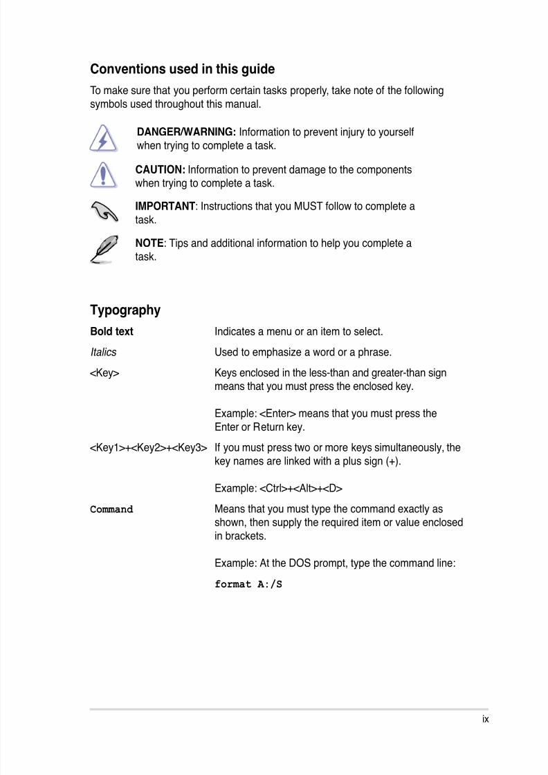
Conventions used in this guide
To make sure that you perform certain tasks properly, take note of the following
symbols used throughout this manual.
DANGER/WARNING: Information to prevent injury to yourselfwhen trying to complete a task.
CAUTION: Information to prevent damage to the componentswhen trying to complete a task.
NOTE: Tips and additional information to help you complete atask.
IMPORTANT: Instructions that you MUST follow to complete a
task.
Typography
Bold text Indicates a menu or an item to select.
Italics Used to emphasize a word or a phrase.
<Key> Keys enclosed in the less-than and greater-than signmeans that you must press the enclosed key.
Example: <Enter> means that you must press the
Enter or Return key.
<Key1>+<Key2>+<Key3> If you must press two or more keys simultaneously, the
key names are linked with a plus sign (+).
Example: <Ctrl>+<Alt>+<D>
Command Means that you must type the command exactly asshown, then supply the required item or value enclosed
in brackets.
Example: At the DOS prompt, type the command line:
format A:/S
8/12/2019 Asus P5QL-EM Manual
http://slidepdf.com/reader/full/asus-p5ql-em-manual 10/112
x
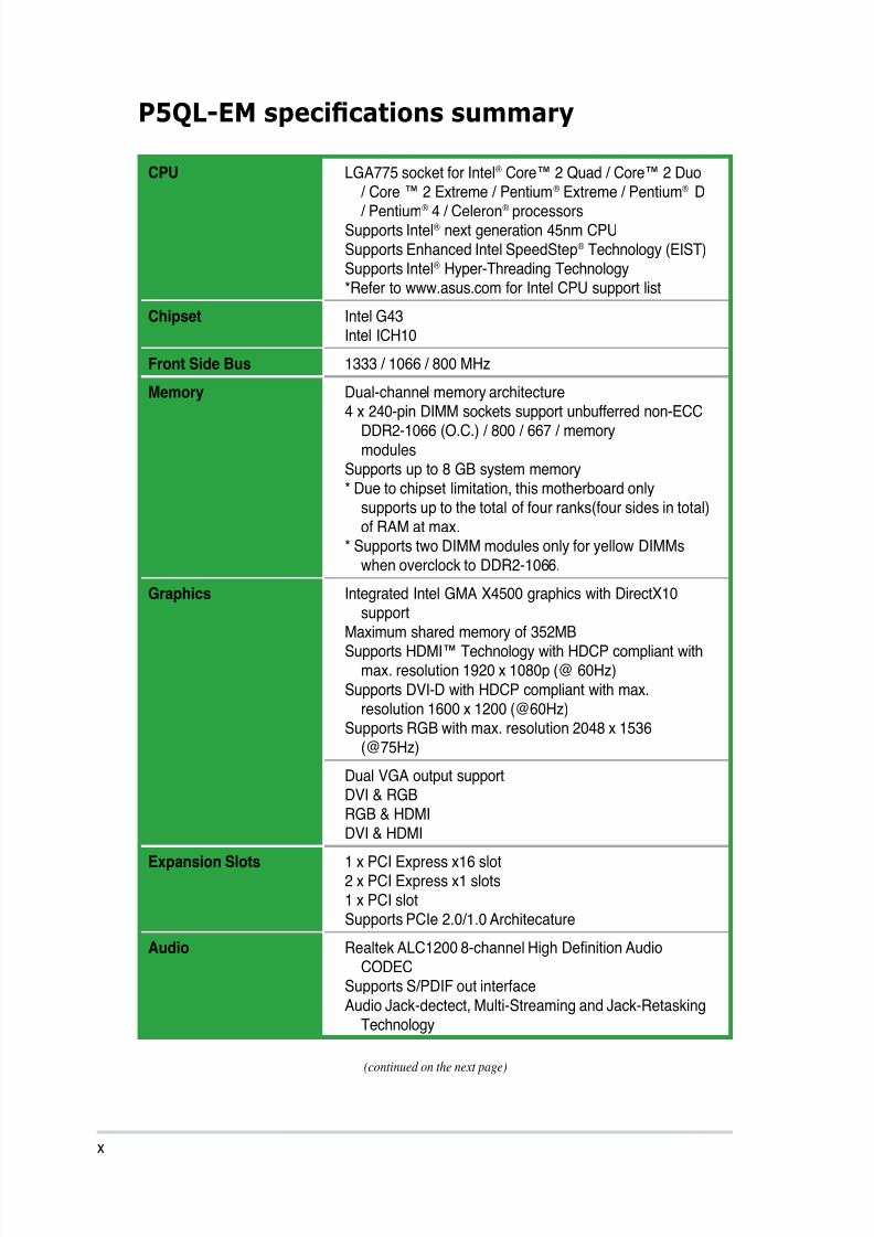
P5QL-EM specifcations summary
(continued on the next page)
CPU LGA775 socket for Intel® Core™ 2 Quad / Core™ 2 Duo
/ Core ™ 2 Extreme / Pentium®
Extreme / Pentium®
D/ Pentium® 4 / Celeron® processorsSupports Intel® next generation 45nm CPUSupports Enhanced Intel SpeedStep® Technology (EIST)Supports Intel® Hyper-Threading Technology*Refer to www.asus.com for Intel CPU support list
Chipset Intel G43Intel ICH10
Front Side Bus 1333 / 1066 / 800 MHz
Memory Dual-channel memory architecture4 x 240-pin DIMM sockets support unbufferred non-ECC
DDR2-1066 (O.C.) / 800 / 667 / memory
modulesSupports up to 8 GB system memory* Due to chipset limitation, this motherboard only
supports up to the total of four ranks(four sides in total)of RAM at max.
* Supports two DIMM modules only for yellow DIMMswhen overclock to DDR2-1066.
Graphics Integrated Intel GMA X4500 graphics with DirectX10support
Maximum shared memory of 352MB Supports HDMI™ Technology with HDCP compliant with
max. resolution 1920 x 1080p (@ 60Hz)
Supports DVI-D with HDCP compliant with max.resolution 1600 x 1200 (@60Hz)
Supports RGB with max. resolution 2048 x 1536(@75Hz)
Dual VGA output support
DVI & RGBRGB & HDMIDVI & HDMI
Expansion Slots 1 x PCI Express x16 slot2 x PCI Express x1 slots 1 x PCI slotSupports PCIe 2.0/1.0 Architecature
Audio Realtek ALC1200 8-channel High Denition AudioCODEC
Supports S/PDIF out interfaceAudio Jack-dectect, Multi-Streaming and Jack-RetaskingTechnology
8/12/2019 Asus P5QL-EM Manual
http://slidepdf.com/reader/full/asus-p5ql-em-manual 11/112
xi
P5QL-EM specifcations summary
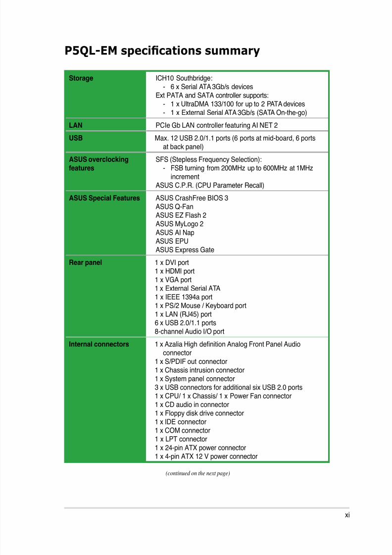
Storage ICH10 Southbridge:
- 6 x Serial ATA 3Gb/s devicesExt PATA and SATA controller supports:
- 1 x UltraDMA 133/100 for up to 2 PATA devices - 1 x External Serial ATA 3Gb/s (SATA On-the-go)
LAN PCIe Gb LAN controller featuring AI NET 2
USB Max. 12 USB 2.0/1.1 ports (6 ports at mid-board, 6 portsat back panel)
ASUS overclocking
featuresSFS (Stepless Frequency Selection):
- FSB turning from 200MHz up to 600MHz at 1MHz
incrementASUS C.P.R. (CPU Parameter Recall)
ASUS Special Features ASUS CrashFree BIOS 3ASUS Q-FanASUS EZ Flash 2 ASUS MyLogo 2
ASUS AI NapASUS EPUASUS Express Gate
Rear panel 1 x DVI port1 x HDMI port1 x VGA port1 x External Serial ATA1 x IEEE 1394a port1 x PS/2 Mouse / Keyboard port 1 x LAN (RJ45) port6 x USB 2.0/1.1 ports 8-channel Audio I/O port
Internal connectors 1 x Azalia High denition Analog Front Panel Audio
connector1 x S/PDIF out connector1 x Chassis intrusion connector1 x System panel connector3 x USB connectors for additional six USB 2.0 ports 1 x CPU/ 1 x Chassis/ 1 x Power Fan connector1 x CD audio in connector1 x Floppy disk drive connector1 x IDE connector1 x COM connector1 x LPT connector
1 x 24-pin ATX power connector 1 x 4-pin ATX 12 V power connector
(continued on the next page)
8/12/2019 Asus P5QL-EM Manual
http://slidepdf.com/reader/full/asus-p5ql-em-manual 12/112
xii
P5QL-EM specifcations summary
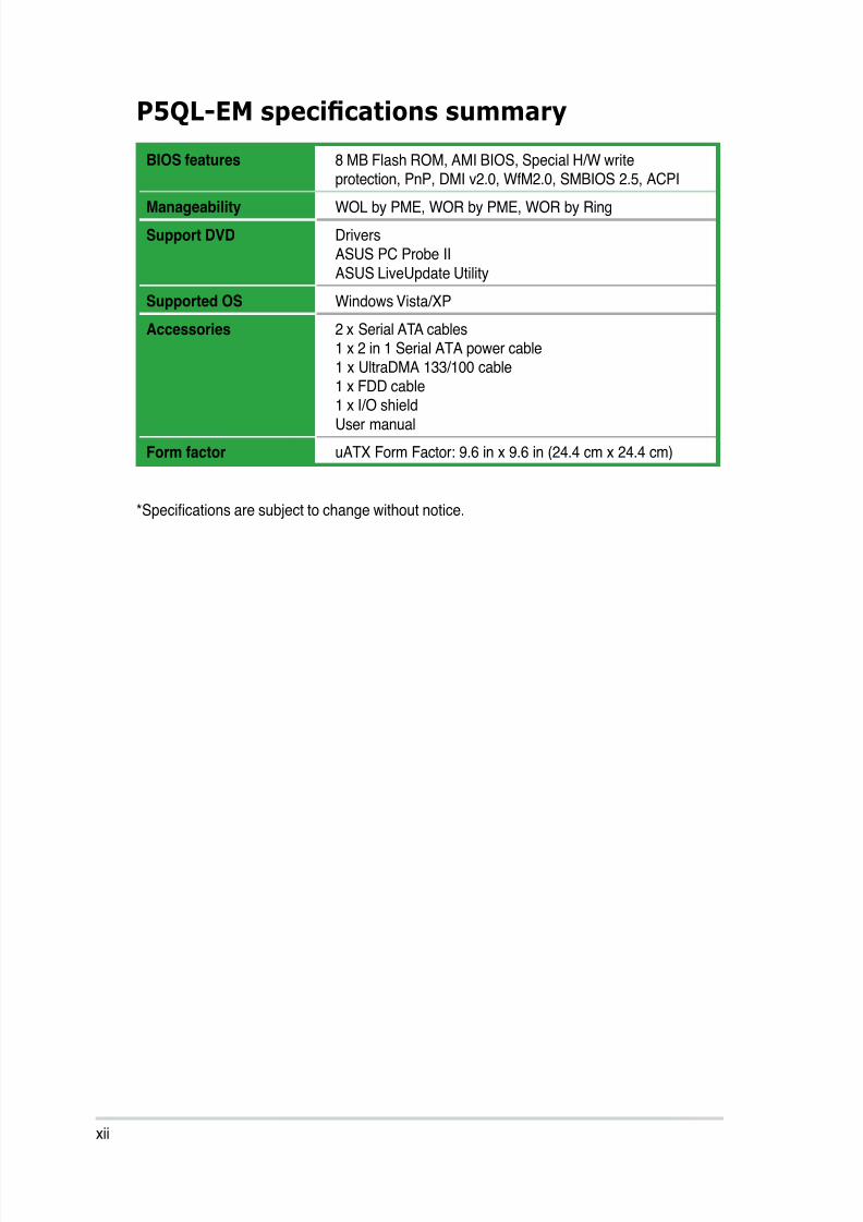
*Specications are subject to change without notice.
BIOS features 8 MB Flash ROM, AMI BIOS, Special H/W writeprotection, PnP, DMI v2.0, WfM2.0, SMBIOS 2.5, ACPI
Manageability WOL by PME, WOR by PME, WOR by Ring
Support DVD DriversASUS PC Probe II
ASUS LiveUpdate Utility
Supported OS Windows Vista/XP
Accessories 2 x Serial ATA cables 1 x 2 in 1 Serial ATA power cable 1 x UltraDMA 133/100 cable
1 x FDD cable1 x I/O shield
User manual
Form factor uATX Form Factor: 9.6 in x 9.6 in (24.4 cm x 24.4 cm)

8/12/2019 Asus P5QL-EM Manual
http://slidepdf.com/reader/full/asus-p5ql-em-manual 13/112
1Product
introduction
This chapter describes the motherboard
features and the new technologiesit supports.
8/12/2019 Asus P5QL-EM Manual
http://slidepdf.com/reader/full/asus-p5ql-em-manual 14/112
1-2 Chapter 1: Product introduction
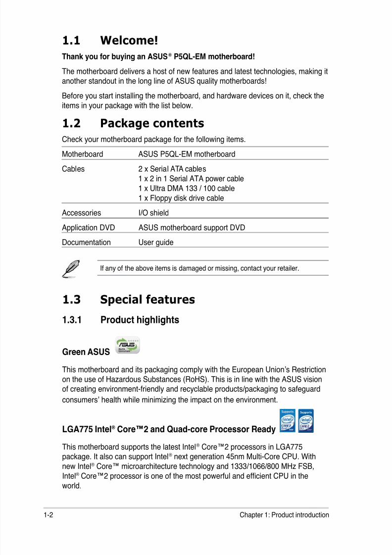
1.1 Welcome!
Thank you for buying an ASUS® P5QL-EM motherboard!
The motherboard delivers a host of new features and latest technologies, making itanother standout in the long line of ASUS quality motherboards!
Before you start installing the motherboard, and hardware devices on it, check the
items in your package with the list below.
1.2 Package contents
Check your motherboard package for the following items.
Motherboard ASUS P5QL-EM motherboard
Cables 2 x Serial ATA cables
1 x 2 in 1 Serial ATA power cable 1 x Ultra DMA 133 / 100 cable
1 x Floppy disk drive cable
Accessories I/O shield
Application DVD ASUS motherboard support DVD
Documentation User guide
If any of the above items is damaged or missing, contact your retailer.
1.3 Special features
1.3.1 Product highlights
Green ASUSThis motherboard and its packaging comply with the European Union’s Restriction
on the use of Hazardous Substances (RoHS). This is in line with the ASUS visionof creating environment-friendly and recyclable products/packaging to safeguard
consumers’ health while minimizing the impact on the environment.
LGA775 Intel® Core™2 and Quad-core Processor Ready
This motherboard supports the latest Intel® Core™2 processors in LGA775package. It also can support Intel® next generation 45nm Multi-Core CPU. With
new Intel® Core™ microarchitecture technology and 1333/1066/800 MHz FSB,
Intel® Core™2 processor is one of the most powerful and efcient CPU in the
world.
8/12/2019 Asus P5QL-EM Manual
http://slidepdf.com/reader/full/asus-p5ql-em-manual 15/112
ASUS P5QL-EM 1-3
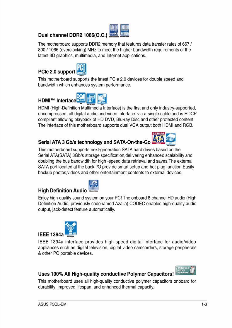
Dual channel DDR2 1066(O.C.)
The motherboard supports DDR2 memory that features data transfer rates of 667 /800 / 1066 (overclocking) MHz to meet the higher bandwidth requirements of the
latest 3D graphics, multimedia, and Internet applications.
PCIe 2.0 support
This motherboard supports the latest PCIe 2.0 devices for double speed and
bandwidth which enhances system performance.
HDMI™ Interface
HDMI (High-Denition Multimedia Interface) is the rst and only industry-supported,
uncompressed, all digital audio and video interface via a single cable and is HDCP
compliant allowing playback of HD DVD, Blu-ray Disc and other protected content.
The interface of this motherboard supports dual VGA output both HDMI and RGB.
Serial ATA 3 Gb/s technology and SATA-On-the-Go
This motherboard supports next-generation SATA hard drives based on the
Serial ATA(SATA) 3Gb/s storage specication,delivering enhanced scalability anddoubling the bus bandwidth for high -speed data retrieval and saves.The external
SATA port located at the back I/O provide smart setup and hot-plug function.Easilybackup photos,videos and other entertainment contents to external devices.
High Denition Audio
Enjoy high-quality sound system on your PC! The onboard 8-channel HD audio (High
Denition Audio, previously codenamed Azalia) CODEC enables high-quality audio
output, jack-detect feature automatically.
IEEE 1394a
IEEE 1394a interface provides high speed digital interface for audio/video
appliances such as digital television, digital video camcorders, storage peripherals& other PC portable devices.
Uses 100% All High-quality conductive Polymer Capacitors!
This motherboard uses all high-quality conductive polymer capacitors onboard for
durability, improved lifespan, and enhanced thermal capacity.
8/12/2019 Asus P5QL-EM Manual
http://slidepdf.com/reader/full/asus-p5ql-em-manual 16/112
1-4 Chapter 1: Product introduction
1.3.2 ASUS Special features
ASUS EPU
The ASUS EPU utilizes innovative technology to digitally monitor and netune the
CPU power supply with improved VR responses in heavy or light loadings.
ASUS AI Nap
Minimize noise and power consumption when temporarily away! With AI Nap,
users can instantly snooze your PC without terminating the tasks. System will
continue operating at minimum power and noise when user is temporarily away.It keeps downloading les or running applications in quietest state while you´resleeping. Simply click keyboard or mouse, you can swiftly wake up the system in
few seconds.
ASUS Q-Fan technology
The ASUS Q-Fan technology smartly adjusts the fan speeds according to the
system loading to ensure quiet, cool, and efcient operation.
C.P.R.(CPU Parameter Recall)
When the system hangs due to overclocking failure, there is no need to open the
case to clear CMOS data. Just simply restart the system, the BIOS would show the
previous setting and then users can amend the CPU setting again.
ASUS MyLogo2™
This feature allows you to convert your favorite photo into a 256-color boot logo for
a more colorful and vivid image on your screen. See page 2-35 for details.
ASUS EZ Flash 2
EZ Flash 2 is a user-friendly BIOS update utility. Simply press the predefined
hotkey to launch the utility and update the BIOS without entering the OS. Updateyour BIOS easily without preparing a bootable diskette or using an OS-based ash
utility. See page 2-4 and 2-38 for details.
8/12/2019 Asus P5QL-EM Manual
http://slidepdf.com/reader/full/asus-p5ql-em-manual 17/112
ASUS P5QL-EM 1-5
ASUS Express Gate
Taking only 5 seconds to go online from bootup, Express Gate is the one-stop
gateway to instant fun! It’s a unique motherboard built-in OS. You can utilize themost popular Instant Messengers (IM) like MSN, Skype, Google talk, QQ, and
Yahoo! Messenger to keep in touch with friends, or quickly check on the weatherand E-mails just before leaving your house. What’s more, the user-friendly picturemanager lets you view your pictures without entering Windows at anytime!
• The actual boot time depends on the system conguration.
• ASUS Express Gate supports le uploading from SATA HDDs, ODDs and
USB drive and downloading to USB drives only.
ASUS CrashFree BIOS 3
The ASUS CrashFree BIOS 3 allows users to restore corrupted BIOS data from a
USB ash disk containing the BIOS le. This utility saves users’ the cost and hassleof buying a replacement BIOS chip.
8/12/2019 Asus P5QL-EM Manual
http://slidepdf.com/reader/full/asus-p5ql-em-manual 18/112
1-6 Chapter 1: Product introduction
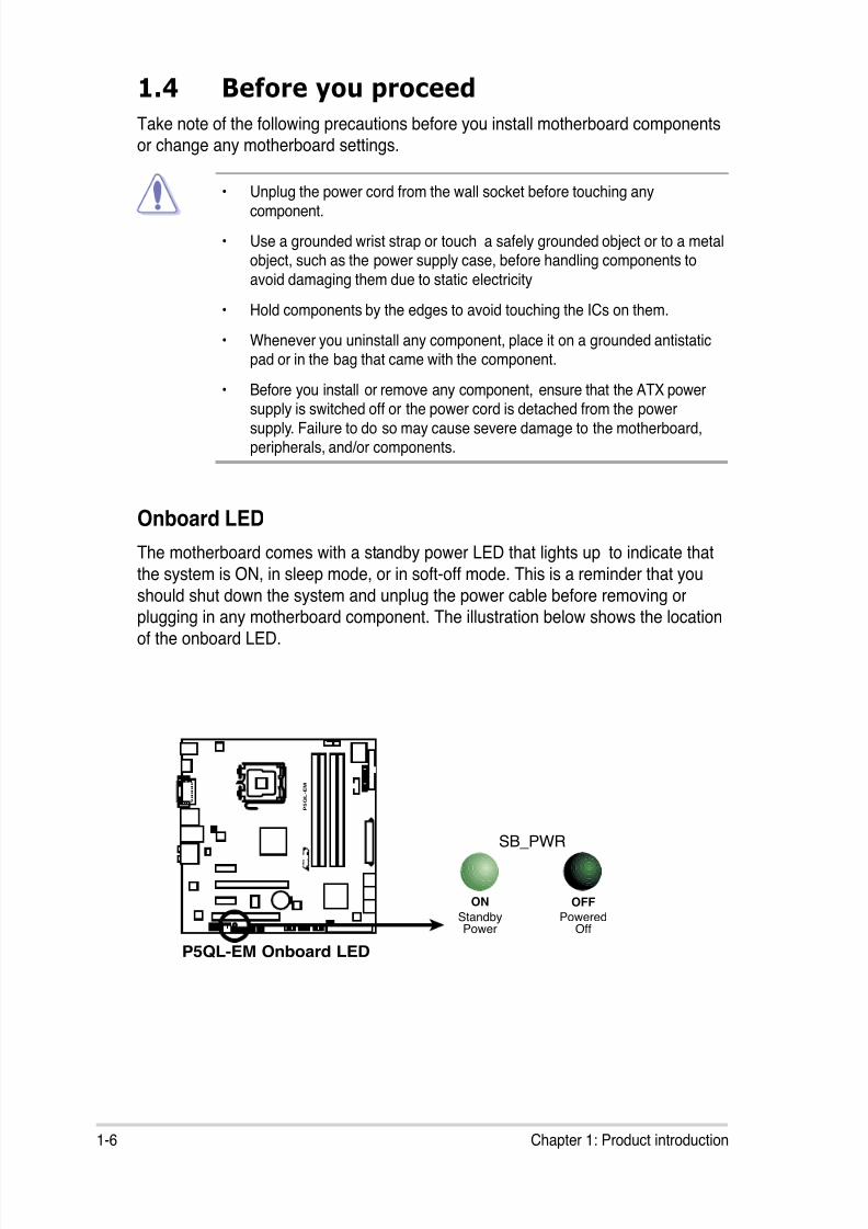
Onboard LED
The motherboard comes with a standby power LED that lights up to indicate that
the system is ON, in sleep mode, or in soft-off mode. This is a reminder that you
should shut down the system and unplug the power cable before removing orplugging in any motherboard component. The illustration below shows the location
of the onboard LED.
1.4 Before you proceed
Take note of the following precautions before you install motherboard componentsor change any motherboard settings.
• Unplug the power cord from the wall socket before touching anycomponent.
• Use a grounded wrist strap or touch a safely grounded object or to a metalobject, such as the power supply case, before handling components to
avoid damaging them due to static electricity
• Hold components by the edges to avoid touching the ICs on them.
• Whenever you uninstall any component, place it on a grounded antistaticpad or in the bag that came with the component.
• Before you install or remove any component, ensure that the ATX powersupply is switched off or the power cord is detached from the power
supply. Failure to do so may cause severe damage to the motherboard,peripherals, and/or components.
P5QL-EM Onboard LED
P 5 Q L - E M
R
SB_PWR
ON
StandbyPower
OFF
PoweredOff
8/12/2019 Asus P5QL-EM Manual
http://slidepdf.com/reader/full/asus-p5ql-em-manual 19/112
ASUS P5QL-EM 1-7
P 5 Q L - E M
R
1.5 Motherboard overview
Before you install the motherboard, study the conguration of your chassis to
ensure that the motherboard ts into it.
Ensure to unplug the power cord before installing or removing the motherboard.
Failure to do so can cause you physical injury and damage motherboardcomponents.
Do not overtighten the screws! Doing so can damage the motherboard.
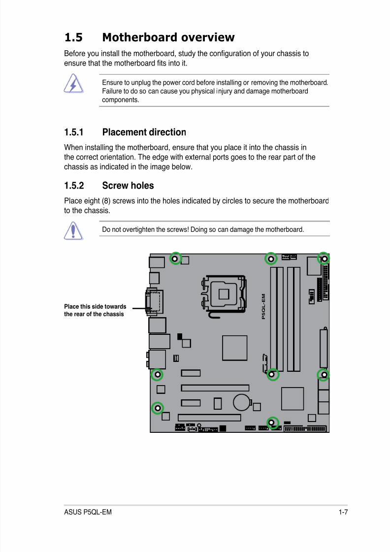
1.5.1 Placement direction
When installing the motherboard, ensure that you place it into the chassis in
the correct orientation. The edge with external ports goes to the rear part of the
chassis as indicated in the image below.
1.5.2 Screw holes
Place eight (8) screws into the holes indicated by circles to secure the motherboard
to the chassis.
Place this side towardsthe rear of the chassis
8/12/2019 Asus P5QL-EM Manual
http://slidepdf.com/reader/full/asus-p5ql-em-manual 20/112
8/12/2019 Asus P5QL-EM Manual
http://slidepdf.com/reader/full/asus-p5ql-em-manual 21/112
ASUS P5QL-EM 1-9
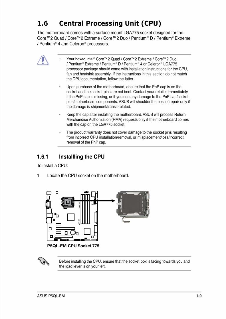
1.6.1 Installling the CPU
To install a CPU:
1. Locate the CPU socket on the motherboard.
1.6 Central Processing Unit (CPU)
The motherboard comes with a surface mount LGA775 socket designed for theCore™2 Quad / Core™2 Extreme / Core™2 Duo / Pentium® D / Pentium® Extreme
/ Pentium® 4 and Celeron® processors.
• Your boxed Intel® Core™2 Quad / Core™2 Extreme / Core™2 Duo/ Pentium® Extreme / Pentium® D / Pentium® 4 or Celeron® LGA775processor package should come with installation instructions for the CPU,
fan and heatsink assembly. If the instructions in this section do not matchthe CPU documentation, follow the latter.
• Upon purchase of the motherboard, ensure that the PnP cap is on thesocket and the socket pins are not bent. Contact your retailer immediatelyif the PnP cap is missing, or if you see any damage to the PnP cap/socket
pins/motherboard components. ASUS will shoulder the cost of repair only ifthe damage is shipment/transit-related.
• Keep the cap after installing the motherboard. ASUS will process ReturnMerchandise Authorization (RMA) requests only if the motherboard comeswith the cap on the LGA775 socket.
• The product warranty does not cover damage to the socket pins resultingfrom incorrect CPU installation/removal, or misplacement/loss/incorrectremoval of the PnP cap.
Before installing the CPU, ensure that the socket box is facing towards you andthe load lever is on your left.
P5QL-EM CPU Socket 775
P 5 Q L - E M
R
8/12/2019 Asus P5QL-EM Manual
http://slidepdf.com/reader/full/asus-p5ql-em-manual 22/112
1-10 Chapter 1: Product introduction
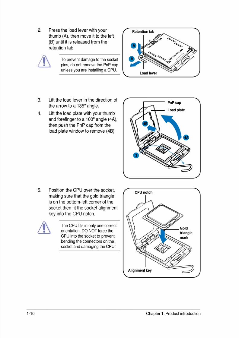
To prevent damage to the socket
pins, do not remove the PnP capunless you are installing a CPU.
2. Press the load lever with yourthumb (A), then move it to the left
(B) until it is released from the
retention tab.A
B
Load lever
Retention tab
3. Lift the load lever in the direction of
the arrow to a 135º angle.4. Lift the load plate with your thumb
and forenger to a 100º angle (4A),
then push the PnP cap from theload plate window to remove (4B).
Load plate
PnP cap
4A
4B
3
5. Position the CPU over the socket,
making sure that the gold triangle
is on the bottom-left corner of thesocket then t the socket alignment
key into the CPU notch.
Goldtrianglemark
Alignment key
CPU notch
The CPU ts in only one correctorientation. DO NOT force theCPU into the socket to preventbending the connectors on thesocket and damaging the CPU!

8/12/2019 Asus P5QL-EM Manual
http://slidepdf.com/reader/full/asus-p5ql-em-manual 23/112
ASUS P5QL-EM 1-11
6. Apply several drops of thermal paste
to the exposed area of the CPU that
the heatsink will be in contact with,
ensuring that it is spread in an even
thin layer.
Some heatsinks come with pre-applied thermal paste. If so, skip
this step.
The Thermal Interface Material is toxic and inedible. If it gets into your eyesor touches your skin, ensure to wash it off immediately, and seek professionalmedical help.
To prevent contaminating the paste, DO NOT spread the paste with your ngerdirectly.
The motherboard supports Intel® LGA775 processors with the Intel® EnhancedMemory 64 Technology (EM64T), Enhanced Intel SpeedStep® Technology(EIST), and Hyper-Threading Technology. Refer to the Appendix for moreinformation on these CPU features.
7. Close the load plate (A), then pushthe load lever (B) until it snaps intothe retention tab.
A
B
8/12/2019 Asus P5QL-EM Manual
http://slidepdf.com/reader/full/asus-p5ql-em-manual 24/112
1-12 Chapter 1: Product introduction
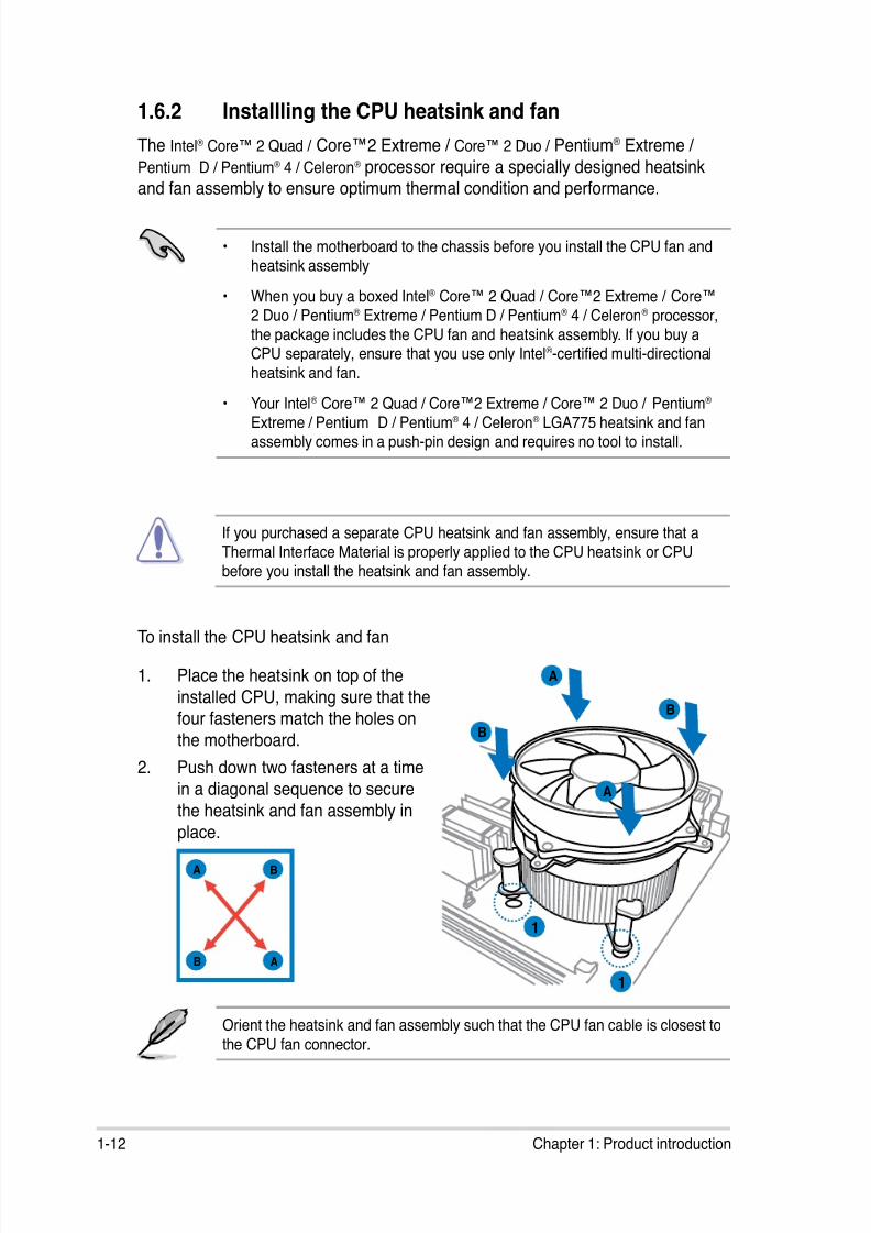
1.6.2 Installling the CPU heatsink and fan
The Intel® Core™ 2 Quad / Core™2 Extreme / Core™ 2 Duo / Pentium® Extreme /
Pentium D / Pentium® 4 / Celeron® processor require a specially designed heatsink
and fan assembly to ensure optimum thermal condition and performance.
• Install the motherboard to the chassis before you install the CPU fan andheatsink assembly
• When you buy a boxed Intel® Core™ 2 Quad / Core™2 Extreme / Core™2 Duo / Pentium® Extreme / Pentium D / Pentium® 4 / Celeron® processor,the package includes the CPU fan and heatsink assembly. If you buy aCPU separately, ensure that you use only Intel®-certied multi-directionalheatsink and fan.
• Your Intel® Core™ 2 Quad / Core™2 Extreme / Core™ 2 Duo / Pentium® Extreme / Pentium D / Pentium® 4 / Celeron® LGA775 heatsink and fanassembly comes in a push-pin design and requires no tool to install.
If you purchased a separate CPU heatsink and fan assembly, ensure that aThermal Interface Material is properly applied to the CPU heatsink or CPUbefore you install the heatsink and fan assembly.
Orient the heatsink and fan assembly such that the CPU fan cable is closest to
the CPU fan connector.
To install the CPU heatsink and fan
1. Place the heatsink on top of the
installed CPU, making sure that thefour fasteners match the holes on
the motherboard.
2. Push down two fasteners at a time
in a diagonal sequence to securethe heatsink and fan assembly in
place.
A
A
B
B
1
1
A B
B A

8/12/2019 Asus P5QL-EM Manual
http://slidepdf.com/reader/full/asus-p5ql-em-manual 25/112
ASUS P5QL-EM 1-13
• Do not forget to connect the CPU fan connector! Hardware monitoringerrors can occur if you fail to plug this connector.
• We recommend you to install the chassis fan for better thermal state.
3. When the fan and heatsink assembly is in place, connect the CPU fan cableto the connector on the motherboard labeled CPU_FAN.
P5QL-EM CPU Fan Connector
P 5 Q L - E M
R
CPU_FAN
G N D
C P U F A N P W R
C P U F A N I N
C P U F A N P W M
8/12/2019 Asus P5QL-EM Manual
http://slidepdf.com/reader/full/asus-p5ql-em-manual 26/112
1-14 Chapter 1: Product introduction
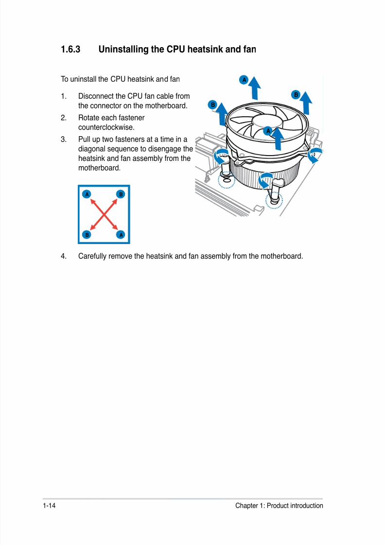
1.6.3 Uninstalling the CPU heatsink and fan
To uninstall the CPU heatsink and fan
1. Disconnect the CPU fan cable from
the connector on the motherboard.
2. Rotate each fastener
counterclockwise.
3. Pull up two fasteners at a time in a
diagonal sequence to disengage the
heatsink and fan assembly from themotherboard.
A
A
B
B
A
A B
B
4. Carefully remove the heatsink and fan assembly from the motherboard.
8/12/2019 Asus P5QL-EM Manual
http://slidepdf.com/reader/full/asus-p5ql-em-manual 27/112
ASUS P5QL-EM 1-15
1.7 System memory
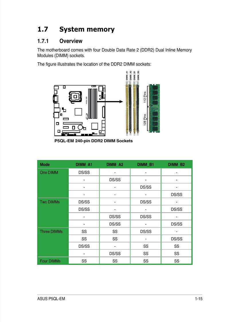
1.7.1 Overview
The motherboard comes with four Double Data Rate 2 (DDR2) Dual Inline MemoryModules (DIMM) sockets.
The gure illustrates the location of the DDR2 DIMM sockets:
P5QL-EM 240-pin DDR2 DIMM Sockets
P
5 Q L - E M
R
1 2 8 P i n s
1 1 2 P i n s
D I M M_
A 2
D I M M_
B 1
D I M M_
B 2
D I M M_
A 1
Mode DIMM_A1 DIMM_A2 DIMM_B1 DIMM_B2
One DIMM DS/SS - - -
- DS/SS - -
- - DS/SS -
- - - DS/SS
Two DIMMs DS/SS - DS/SS -
DS/SS - - DS/SS
- DS/SS DS/SS -
- DS/SS - DS/SS
Three DIMMs SS SS DS/SS -
SS SS - DS/SS
DS/SS - SS SS
- DS/SS SS SS
Four DIMMs SS SS SS SS
8/12/2019 Asus P5QL-EM Manual
http://slidepdf.com/reader/full/asus-p5ql-em-manual 28/112
1-16 Chapter 1: Product introduction
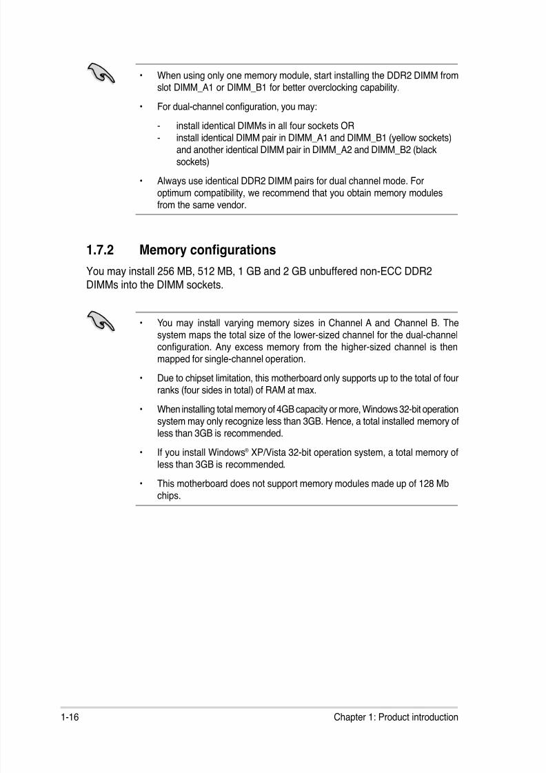
1.7.2 Memory congurations
You may install 256 MB, 512 MB, 1 GB and 2 GB unbuffered non-ECC DDR2
DIMMs into the DIMM sockets.
• You may install varying memory sizes in Channel A and Channel B. Thesystem maps the total size of the lower-sized channel for the dual-channelconguration. Any excess memory from the higher-sized channel is thenmapped for single-channel operation.
• Due to chipset limitation, this motherboard only supports up to the total of fourranks (four sides in total) of RAM at max.
• When installing total memory of 4GB capacity or more, Windows 32-bit operationsystem may only recognize less than 3GB. Hence, a total installed memory ofless than 3GB is recommended.
• If you install Windows® XP/Vista 32-bit operation system, a total memory ofless than 3GB is recommended.
• This motherboard does not support memory modules made up of 128 Mb
chips.
• When using only one memory module, start installing the DDR2 DIMM fromslot DIMM_A1 or DIMM_B1 for better overclocking capability.
• For dual-channel conguration, you may:
- install identical DIMMs in all four sockets OR- install identical DIMM pair in DIMM_A1 and DIMM_B1 (yellow sockets)
and another identical DIMM pair in DIMM_A2 and DIMM_B2 (blacksockets)
• Always use identical DDR2 DIMM pairs for dual channel mode. Foroptimum compatibility, we recommend that you obtain memory modulesfrom the same vendor.
8/12/2019 Asus P5QL-EM Manual
http://slidepdf.com/reader/full/asus-p5ql-em-manual 29/112
ASUS P5QL-EM 1-17
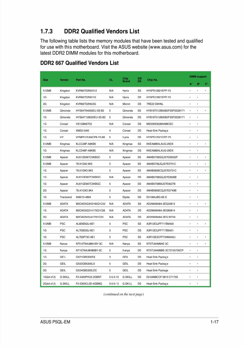
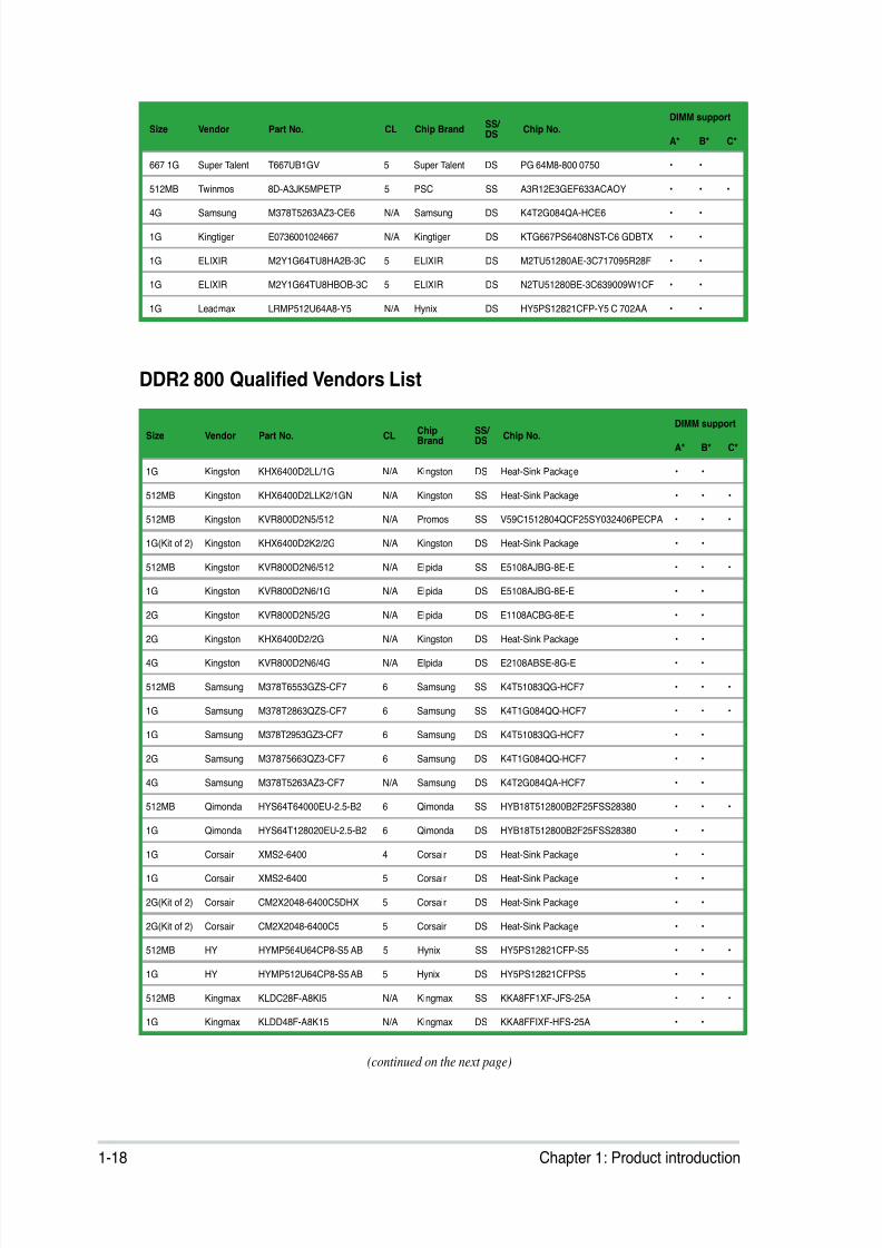
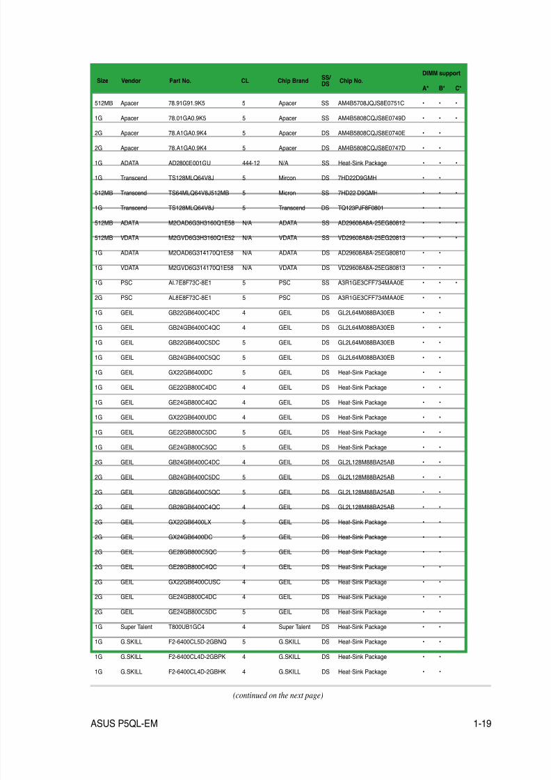
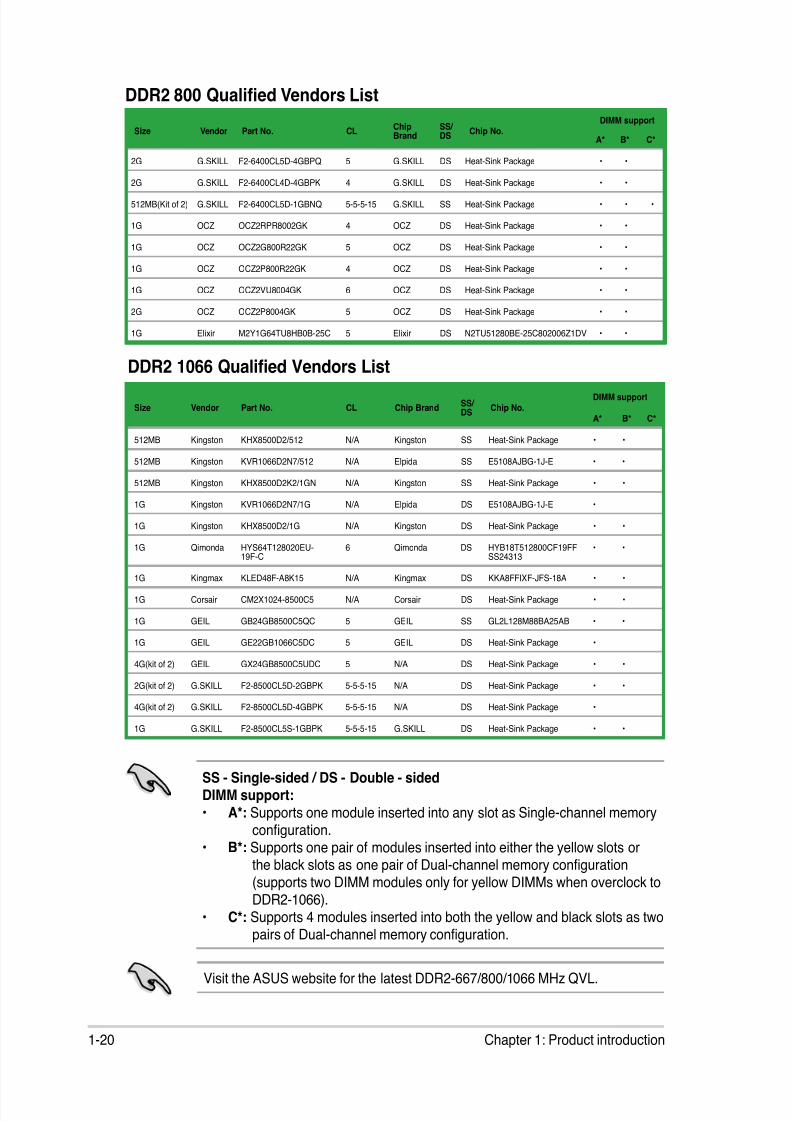
1.7.3 DDR2 Qualied Vendors List
The following table lists the memory modules that have been tested and qualied
for use with this motherboard. Visit the ASUS website (www.asus.com) for the
latest DDR2 DIMM modules for this motherboard.DDR2 667 Qualied Vendors List
(continued on the next page)
Size Vendor Part No. CLChipBrand
SS/ DS
Chip No.DIMM support
A* B* C*
512MB Kingston KVR667D2N5/512 N/A Hynix SS HY5PS12821EFP-Y5 • • •
1G Kingston KVR667D2N5/1G N/A Hynix DS HY5PS12821EFP-Y5 • •
2G Kingston KVR667D2N5/2G N/A Micron DS 7RE22 D9HNL • •
512MB Qimonda HYS64T64000EU-3S-B2 5 Qimonda SS HYB18T512B00B2F3SFSS28171 • • •
1G Qimonda HYS64T128020EU-3S-B2 5 Qimonda DS HYB18T512B00B2F3SFSS28171 • •
1G Corsair VS1GB667D2 N/A Corsair DS MID095D62864M8CEC • •
1G Corsair XMS2-5400 4 Corsair DS Heat-Sink Package • •
1G HY HYMP512U64CP8-Y5 AB 5 Hynix DS HY5PS12521CFP-Y5 • •
512MB Kingmax KLCC28F-A8KB5 N/A Kingmax SS KKEA88B4LAUG-29DX • • •
1G Kingmax KLCD48F-A8KB5 N/A Kingmax DS KKEA88B4LAUG-29DX • •
512MB Apacer AU512E667C5KBGC 5 Apacer SS AM4B5708GQJS7E06332F • • •
512MB Apacer 78.91G92.9K5 5 Apacer SS AM4B5708JQJS7E0751C • • •
1G Apacer 78.01G9O.9K5 5 Apacer SS AM4B5808CQJS7E0751C • • •
1G Apacer AU01GE667C5KBGC N/A Apacer DS AM4B5708GQJS7E0636B • •
1G Apacer AU01GE667C5KBGC 5 Apacer DS AM4B5708MIJS7E0627B • •
2G Apacer 78.A1G9O.9K4 5 Apacer DS AM4B5808CQJS7E0749B • •
1G Transcend 506010-4894 5 Elpida DS E5108AJBG-6E-E • •
512MB ADATA M2OAD5G3H3160Q1C52 N/A ADATA SS AD29608A8A-3EG20813 • • •
1G ADATA M2OAD5G314170Q1C58 N/A ADATA DS AD29608A8A-3EG80814 • •
2G ADATA M2OAD5H3J4170I1C53 N/A ADATA DS AD20908A8A-3EG 30724 • •
512MB PSC AL6E8E63J-6E1 5 PSC SS A3R12E3JFF717B9A00 • • •
1G PSC AL7E8E63J-6E1 5 PSC DS A3R12E3JFF717B9A01 • •
1G PSC AL7E8F73C-6E1 5 PSC SS A3R1GE3CFF734MAA0J • • •
512MB Nanya NT512T64U88A1BY-3C N/A Nanya SS NT5TU64M8AE-3C • • •
1G Nanya NT1GT64U8HB0BY-3C 5 Nanya DS NT5TU64M8BE-3C72155700CP • •
1G GEIL GX21GB5300SX 3 GEIL DS Heat-Sink Package • •
2G GEIL GX22GB5300LX 5 GEIL DS Heat-Sink Package • •
2G GEIL GX24GB5300LDC 5 GEIL DS Heat-Sink Package • •
1G(kit of 2) G.SKILL F2-5400PHU2-2GBNT 5-5-5-15 G.SKILL DS D2 64M8CCF 0815 C7173S • •
2G(kit of 2) G.SKILL F2-5300CL5D-4GBMQ 5-5-5-15 G.SKILL DS Heat-Sink Package • •
8/12/2019 Asus P5QL-EM Manual
http://slidepdf.com/reader/full/asus-p5ql-em-manual 30/112
1-18 Chapter 1: Product introduction
DDR2 800 Qualied Vendors List
Size Vendor Part No. CL Chip BrandSS/ DS
Chip No.DIMM support
A* B* C*
667 1G Super Talent T667UB1GV 5 Super Talent DS PG 64M8-800 0750 • •
512MB Twinmos 8D-A3JK5MPETP 5 PSC SS A3R12E3GEF633ACAOY • • •
4G Samsung M378T5263AZ3-CE6 N/A Samsung DS K4T2G084QA-HCE6 • •
1G Kingtiger E0736001024667 N/A Kingtiger DS KTG667PS6408NST-C6 GDBTX • •
1G ELIXIR M2Y1G64TU8HA2B-3C 5 ELIXIR DS M2TU51280AE-3C717095R28F • •
1G ELIXIR M2Y1G64TU8HBOB-3C 5 ELIXIR DS N2TU51280BE-3C639009W1CF • •
1G Leadmax LRMP512U64A8-Y5 N/A Hynix DS HY5PS12821CFP-Y5 C 702AA • •
Size Vendor Part No. CLChipBrand
SS/ DS
Chip No.DIMM support
A* B* C*
1G Kingston KHX6400D2LL/1G N/A Kingston DS Heat-Sink Package • •
512MB Kingston KHX6400D2LLK2/1GN N/A Kingston SS Heat-Sink Package • • •
512MB Kingston KVR800D2N5/512 N/A Promos SS V59C1512804QCF25SY032406PECPA • • •
1G(Kit of 2) Kingston KHX6400D2K2/2G N/A Kingston DS Heat-Sink Package • •
512MB Kingston KVR800D2N6/512 N/A Elpida SS E5108AJBG-8E-E • • •
1G Kingston KVR800D2N6/1G N/A Elpida DS E5108AJBG-8E-E • •
2G Kingston KVR800D2N5/2G N/A Elpida DS E1108ACBG-8E-E • •
2G Kingston KHX6400D2/2G N/A Kingston DS Heat-Sink Package • •
4G Kingston KVR800D2N6/4G N/A Elpida DS E2108ABSE-8G-E • •
512MB Samsung M378T6553GZS-CF7 6 Samsung SS K4T51083QG-HCF7 • • •
1G Samsung M378T2863QZS-CF7 6 Samsung SS K4T1G084QQ-HCF7 • • •
1G Samsung M378T2953GZ3-CF7 6 Samsung DS K4T51083QG-HCF7 • •
2G Samsung M37875663QZ3-CF7 6 Samsung DS K4T1G084QQ-HCF7 • •
4G Samsung M378T5263AZ3-CF7 N/A Samsung DS K4T2G084QA-HCF7 • •
512MB Qimonda HYS64T64000EU-2.5-B2 6 Qimonda SS HYB18T512800B2F25FSS28380 • • •
1G Qimonda HYS64T128020EU-2.5-B2 6 Qimonda DS HYB18T512800B2F25FSS28380 • •
1G Corsair XMS2-6400 4 Corsair DS Heat-Sink Package • •
1G Corsair XMS2-6400 5 Corsair DS Heat-Sink Package • •
2G(Kit of 2) Corsair CM2X2048-6400C5DHX 5 Corsair DS Heat-Sink Package • •
2G(Kit of 2) Corsair CM2X2048-6400C5 5 Corsair DS Heat-Sink Package • •
512MB HY HYMP564U64CP8-S5 AB 5 Hynix SS HY5PS12821CFP-S5 • • •
1G HY HYMP512U64CP8-S5 AB 5 Hynix DS HY5PS12821CFPS5 • •
512MB Kingmax KLDC28F-A8KI5 N/A Kingmax SS KKA8FF1XF-JFS-25A • • •
1G Kingmax KLDD48F-A8K15 N/A Kingmax DS KKA8FFIXF-HFS-25A • •
(continued on the next page)
8/12/2019 Asus P5QL-EM Manual
http://slidepdf.com/reader/full/asus-p5ql-em-manual 31/112
ASUS P5QL-EM 1-19
Size Vendor Part No. CL Chip BrandSS/ DS
Chip No.DIMM support
A* B* C*
512MB Apacer 78.91G91.9K5 5 Apacer SS AM4B5708JQJS8E0751C • • •
1G Apacer 78.01GA0.9K5 5 Apacer SS AM4B5808CQJS8E0749D • • •
2G Apacer 78.A1GA0.9K4 5 Apacer DS AM4B5808CQJS8E0740E • •
2G Apacer 78.A1GA0.9K4 5 Apacer DS AM4B5808CQJS8E0747D • •
1G ADATA AD2800E001GU 444-12 N/A SS Heat-Sink Package • • •
1G Transcend TS128MLQ64V8J 5 Mircon DS 7HD22D9GMH • •
512MB Transcend TS64MLQ64V8J512MB 5 Micron SS 7HD22 D9GMH • • •
1G Transcend TS128MLQ64V8J 5 Transcend DS TQ123PJF8F0801 • •
512MB ADATA M2OAD6G3H3160Q1E58 N/A ADATA SS AD29608A8A-25EG80812 • • •
512MB VDATA M2GVD6G3H3160Q1E52 N/A VDATA SS VD29608A8A-25EG20813 • • •
1G ADATA M2OAD6G314170Q1E58 N/A ADATA DS AD29608A8A-25EG80810 • •
1G VDATA M2GVD6G314170Q1E58 N/A VDATA DS VD29608A8A-25EG80813 • •
1G PSC AL7E8F73C-8E1 5 PSC SS A3R1GE3CFF734MAA0E • • •
2G PSC AL8E8F73C-8E1 5 PSC DS A3R1GE3CFF734MAA0E • •
1G GEIL GB22GB6400C4DC 4 GEIL DS GL2L64M088BA30EB • •
1G GEIL GB24GB6400C4QC 4 GEIL DS GL2L64M088BA30EB • •
1G GEIL GB22GB6400C5DC 5 GEIL DS GL2L64M088BA30EB • •
1G GEIL GB24GB6400C5QC 5 GEIL DS GL2L64M088BA30EB • •
1G GEIL GX22GB6400DC 5 GEIL DS Heat-Sink Package • •
1G GEIL GE22GB800C4DC 4 GEIL DS Heat-Sink Package • •
1G GEIL GE24GB800C4QC 4 GEIL DS Heat-Sink Package • •
1G GEIL GX22GB6400UDC 4 GEIL DS Heat-Sink Package • •
1G GEIL GE22GB800C5DC 5 GEIL DS Heat-Sink Package • •
1G GEIL GE24GB800C5QC 5 GEIL DS Heat-Sink Package • •
2G GEIL GB24GB6400C4DC 4 GEIL DS GL2L128M88BA25AB • •
2G GEIL GB24GB6400C5DC 5 GEIL DS GL2L128M88BA25AB • •
2G GEIL GB28GB6400C5QC 5 GEIL DS GL2L128M88BA25AB • •
2G GEIL GB28GB6400C4QC 4 GEIL DS GL2L128M88BA25AB • •
2G GEIL GX22GB6400LX 5 GEIL DS Heat-Sink Package • •
2G GEIL GX24GB6400DC 5 GEIL DS Heat-Sink Package • •
2G GEIL GE28GB800C5QC 5 GEIL DS Heat-Sink Package • •
2G GEIL GE28GB800C4QC 4 GEIL DS Heat-Sink Package • •
2G GEIL GX22GB6400CUSC 4 GEIL DS Heat-Sink Package • •
2G GEIL GE24GB800C4DC 4 GEIL DS Heat-Sink Package • •
2G GEIL GE24GB800C5DC 5 GEIL DS Heat-Sink Package • •
1G Super Talent T800UB1GC4 4 Super Talent DS Heat-Sink Package • •
1G G.SKILL F2-6400CL5D-2GBNQ 5 G.SKILL DS Heat-Sink Package • •
1G G.SKILL F2-6400CL4D-2GBPK 4 G.SKILL DS Heat-Sink Package • •
1G G.SKILL F2-6400CL4D-2GBHK 4 G.SKILL DS Heat-Sink Package • •
(continued on the next page)
8/12/2019 Asus P5QL-EM Manual
http://slidepdf.com/reader/full/asus-p5ql-em-manual 32/112
8/12/2019 Asus P5QL-EM Manual
http://slidepdf.com/reader/full/asus-p5ql-em-manual 33/112
ASUS P5QL-EM 1-21
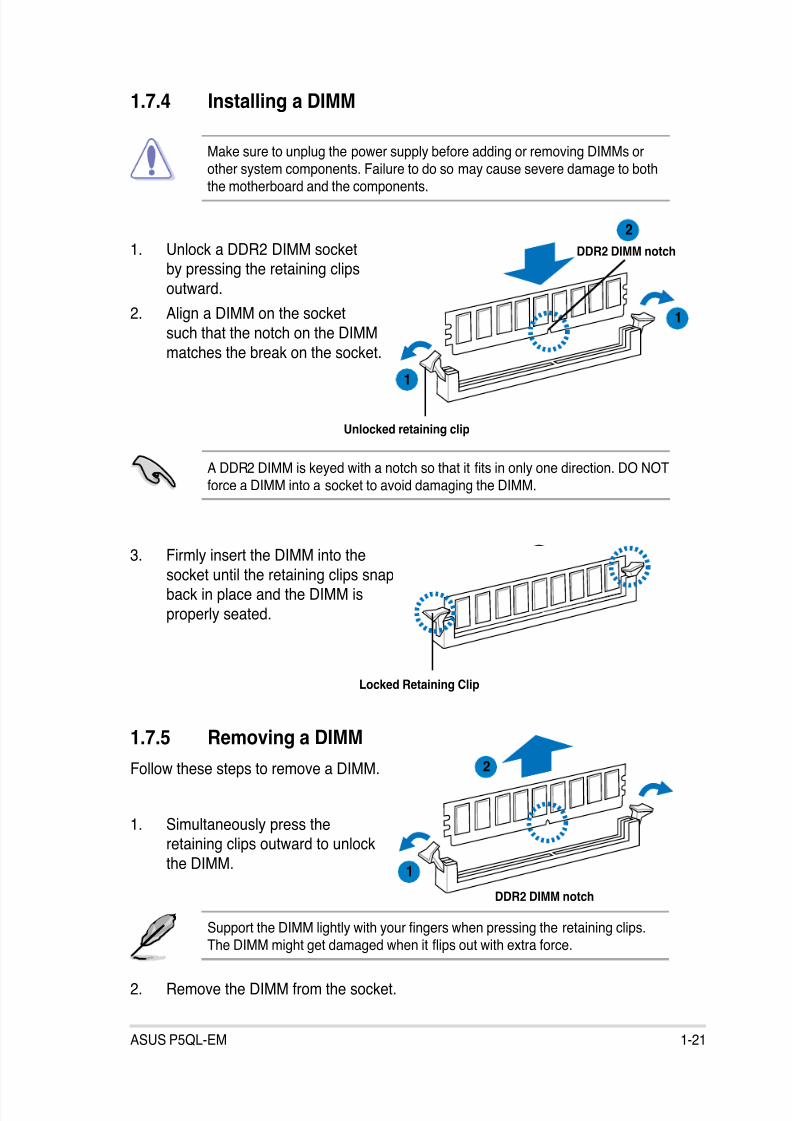
1.7.4 Installing a DIMM
3. Firmly insert the DIMM into the
socket until the retaining clips snapback in place and the DIMM is
properly seated.
A DDR2 DIMM is keyed with a notch so that it ts in only one direction. DO NOTforce a DIMM into a socket to avoid damaging the DIMM.
Make sure to unplug the power supply before adding or removing DIMMs orother system components. Failure to do so may cause severe damage to boththe motherboard and the components.
3
Unlocked retaining clip
1
DDR2 DIMM notch1. Unlock a DDR2 DIMM socketby pressing the retaining clips
outward.
2. Align a DIMM on the socket
such that the notch on the DIMM
matches the break on the socket.
Locked Retaining Clip
2
1
1.7.5 Removing a DIMM
Follow these steps to remove a DIMM.
1. Simultaneously press theretaining clips outward to unlock
the DIMM.
2. Remove the DIMM from the socket.
Support the DIMM lightly with your ngers when pressing the retaining clips.The DIMM might get damaged when it ips out with extra force.
DDR2 DIMM notch
1
2

8/12/2019 Asus P5QL-EM Manual
http://slidepdf.com/reader/full/asus-p5ql-em-manual 34/112
1-22 Chapter 1: Product introduction
1.8 Expansion slots
In the future, you may need to install expansion cards. The following sub-sectionsdescribe the slots and the expansion cards that they support.
1.8.1 Installing an expansion card
To install an expansion card:
1. Before installing the expansion card, read the documentation that came with
it and make the necessary hardware settings for the card.
2. Remove the system unit cover (if your motherboard is already installed in a
chassis).
3. Remove the bracket opposite the slot that you intend to use. Keep the screw
for later use.
4. Align the card connector with the slot and press rmly until the card iscompletely seated on the slot.
5. Secure the card to the chassis with the screw you removed earlier.
6. Replace the system cover.
1.8.2 Conguring an expansion card
After installing the expansion card, congure it by adjusting the software settings.
1. Turn on the system and change the necessary BIOS settings, if any. See
Chapter 2 for information on BIOS setup.
2. Assign an IRQ to the card. Refer to the tables on the next page.
3. Install the software drivers for the expansion card.
Ensure to unplug the power cord before adding or removing expansion cards.Failure to do so may cause you physical injury and damage motherboardcomponents.
8/12/2019 Asus P5QL-EM Manual
http://slidepdf.com/reader/full/asus-p5ql-em-manual 35/112
ASUS P5QL-EM 1-23
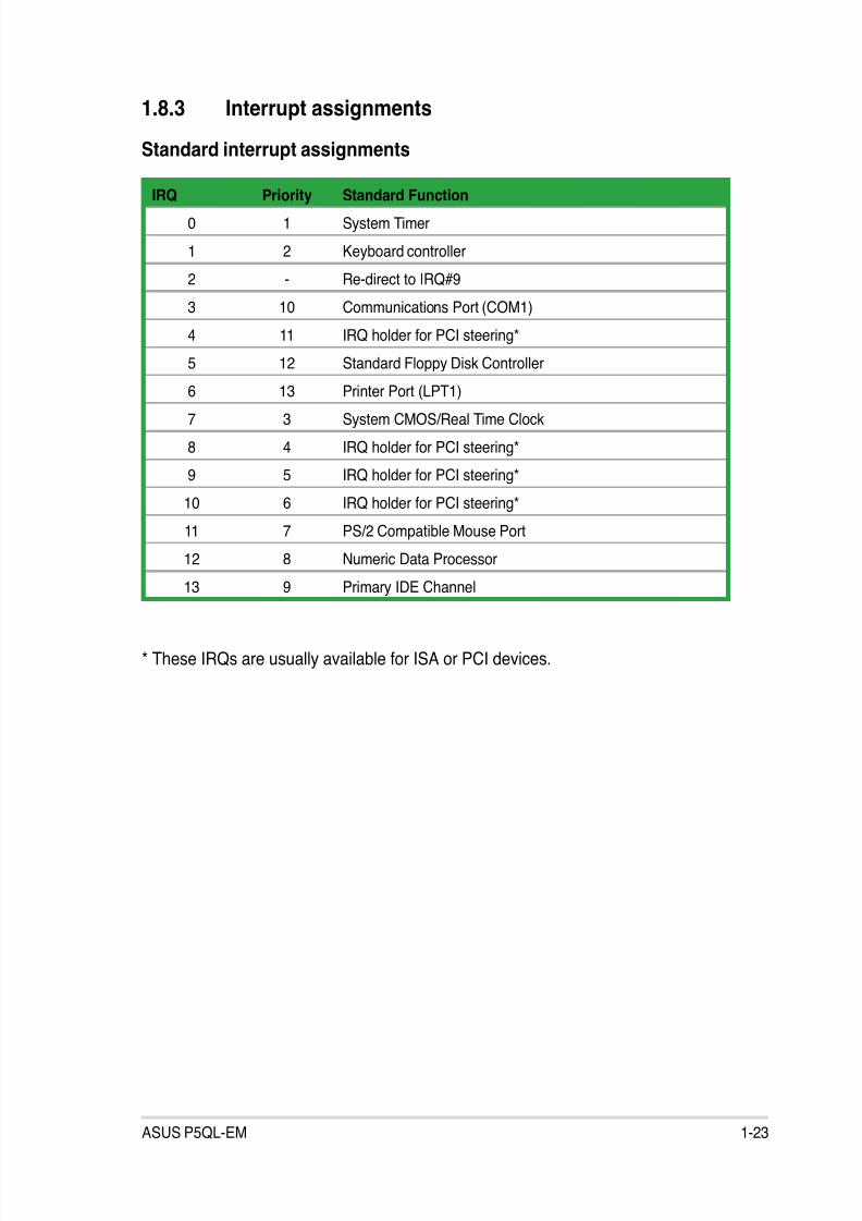
1.8.3 Interrupt assignments
Standard interrupt assignments
* These IRQs are usually available for ISA or PCI devices.
IRQ Priority Standard Function
0 1 System Timer
1 2 Keyboard controller
2 - Re-direct to IRQ#9
3 10 Communications Port (COM1)
4 11 IRQ holder for PCI steering*
5 12 Standard Floppy Disk Controller
6 13 Printer Port (LPT1)
7 3 System CMOS/Real Time Clock
8 4 IRQ holder for PCI steering*
9 5 IRQ holder for PCI steering*
10 6 IRQ holder for PCI steering*
11 7 PS/2 Compatible Mouse Port
12 8 Numeric Data Processor
13 9 Primary IDE Channel
8/12/2019 Asus P5QL-EM Manual
http://slidepdf.com/reader/full/asus-p5ql-em-manual 36/112
1-24 Chapter 1: Product introduction
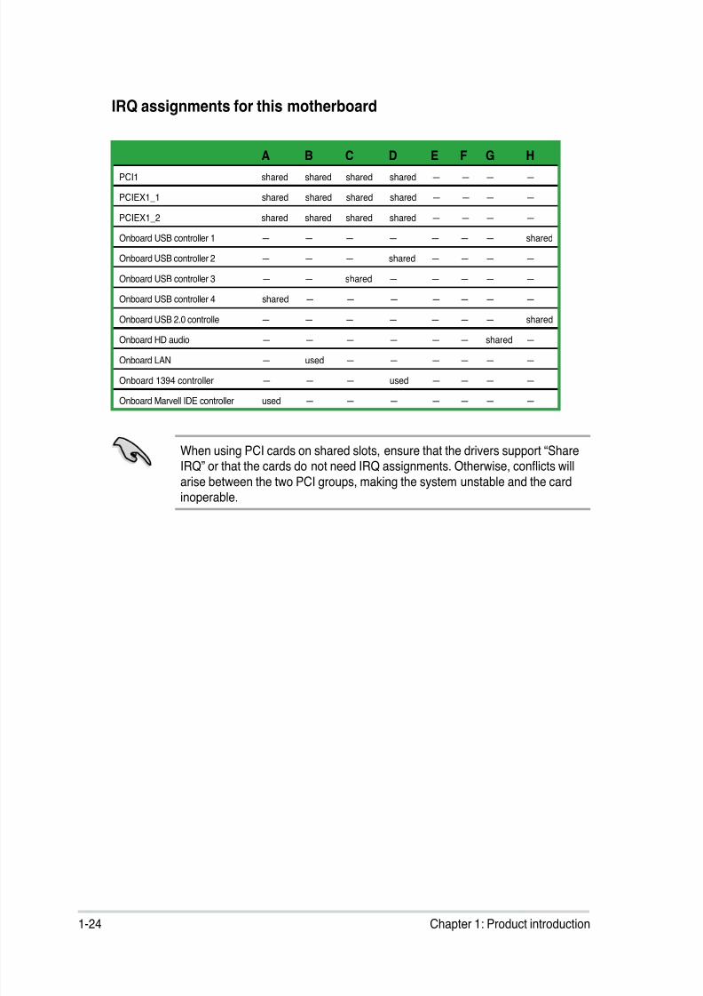
IRQ assignments for this motherboard
When using PCI cards on shared slots, ensure that the drivers support “ShareIRQ” or that the cards do not need IRQ assignments. Otherwise, conicts will
arise between the two PCI groups, making the system unstable and the cardinoperable.
A B C D E F G HPCI1 shared shared shared shared — — — —
PCIEX1_1 shared shared shared shared — — — —
PCIEX1_2 shared shared shared shared — — — —
Onboard USB controller 1 — — — — — — — shared
Onboard USB controller 2 — — — shared — — — —
Onboard USB controller 3 — — shared — — — — —
Onboard USB controller 4 shared — — — — — — —
Onboard USB 2.0 controlle — — — — — — — shared
Onboard HD audio — — — — — — shared —
Onboard LAN — used — — — — — —
Onboard 1394 controller — — — used — — — —
Onboard Marvell IDE controller used — — — — — — —
8/12/2019 Asus P5QL-EM Manual
http://slidepdf.com/reader/full/asus-p5ql-em-manual 37/112
ASUS P5QL-EM 1-25
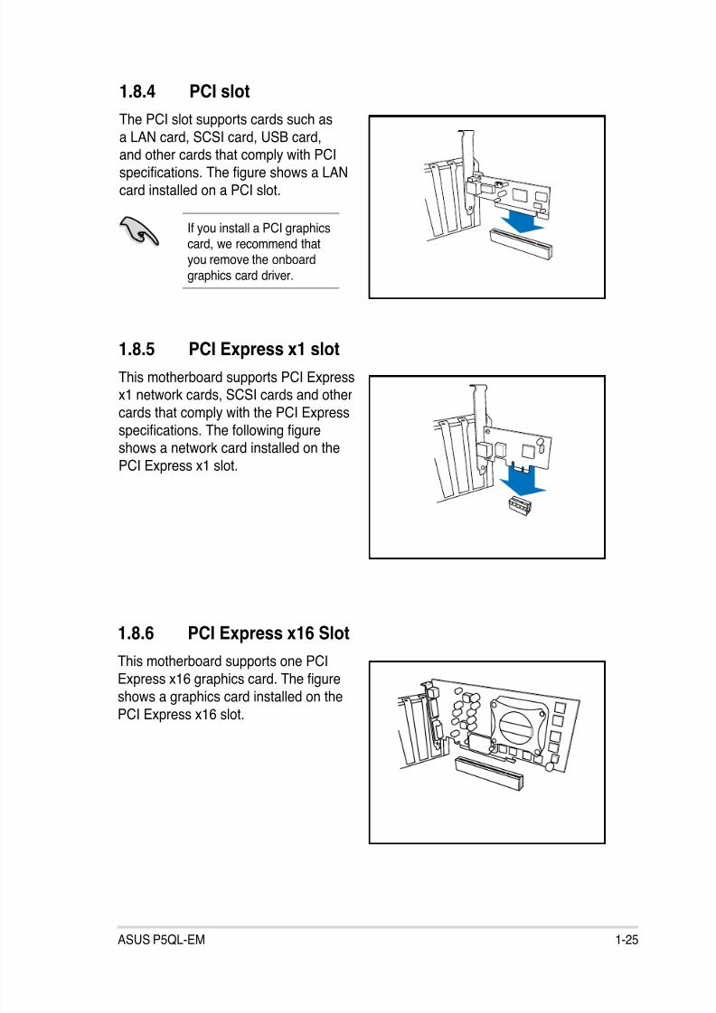
1.8.4 PCI slot
The PCI slot supports cards such as
a LAN card, SCSI card, USB card,
and other cards that comply with PCIspecications. The gure shows a LAN
card installed on a PCI slot.
1.8.6 PCI Express x16 Slot
This motherboard supports one PCI
Express x16 graphics card. The gure
shows a graphics card installed on the
PCI Express x16 slot.
If you install a PCI graphicscard, we recommend thatyou remove the onboard
graphics card driver.
1.8.5 PCI Express x1 slot
This motherboard supports PCI Expressx1 network cards, SCSI cards and other
cards that comply with the PCI Express
specications. The following gureshows a network card installed on the
PCI Express x1 slot.
8/12/2019 Asus P5QL-EM Manual
http://slidepdf.com/reader/full/asus-p5ql-em-manual 38/112
1-26 Chapter 1: Product introduction
1.9 Jumpers
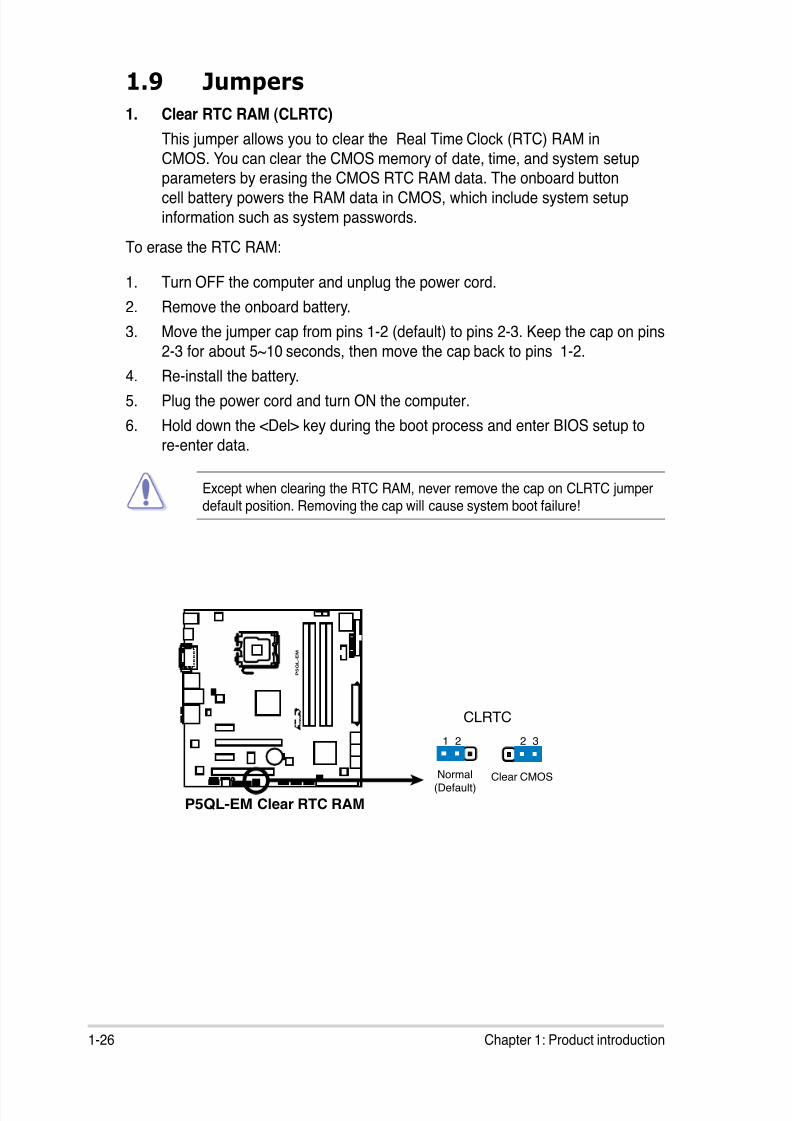
1. Clear RTC RAM (CLRTC)
This jumper allows you to clear the Real Time Clock (RTC) RAM in
CMOS. You can clear the CMOS memory of date, time, and system setup
parameters by erasing the CMOS RTC RAM data. The onboard buttoncell battery powers the RAM data in CMOS, which include system setup
information such as system passwords.
To erase the RTC RAM:
1. Turn OFF the computer and unplug the power cord.
2. Remove the onboard battery.
3. Move the jumper cap from pins 1-2 (default) to pins 2-3. Keep the cap on pins
2-3 for about 5~10 seconds, then move the cap back to pins 1-2.4. Re-install the battery.
5. Plug the power cord and turn ON the computer.
6. Hold down the <Del> key during the boot process and enter BIOS setup to
re-enter data.
Except when clearing the RTC RAM, never remove the cap on CLRTC jumperdefault position. Removing the cap will cause system boot failure!
P5QL-EM Clear RTC RAM
P 5 Q L - E M
R
CLRTC
Normal Clear CMOS(Default)
1 2 2 3
8/12/2019 Asus P5QL-EM Manual
http://slidepdf.com/reader/full/asus-p5ql-em-manual 39/112
ASUS P5QL-EM 1-27
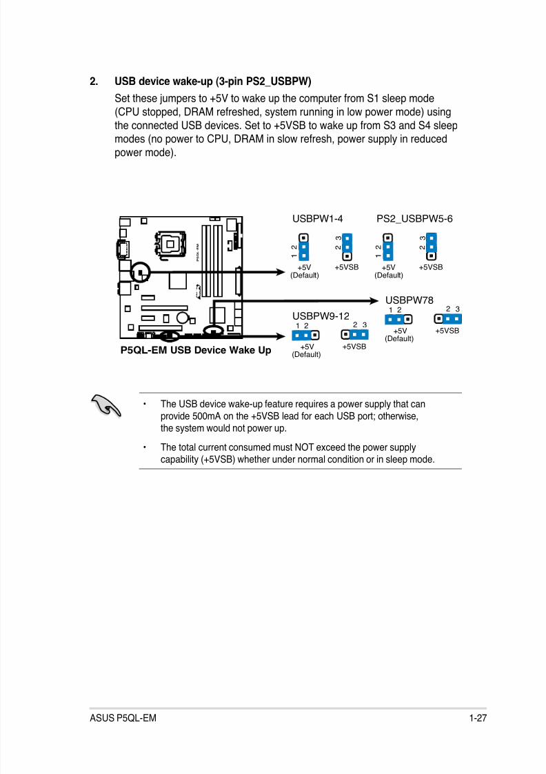
2. USB device wake-up (3-pin PS2_USBPW)
Set these jumpers to +5V to wake up the computer from S1 sleep mode
(CPU stopped, DRAM refreshed, system running in low power mode) using
the connected USB devices. Set to +5VSB to wake up from S3 and S4 sleepmodes (no power to CPU, DRAM in slow refresh, power supply in reduced
power mode).
• The USB device wake-up feature requires a power supply that can
provide 500mA on the +5VSB lead for each USB port; otherwise,the system would not power up.
• The total current consumed must NOT exceed the power supplycapability (+5VSB) whether under normal condition or in sleep mode.
P5QL-EM USB Device Wake Up
P 5 Q L - E
M
R
3
2 2
1
USBPW1-4
+5V
(Default)+5VSB
3
2 2
1
PS2_USBPW5-6
+5V
(Default)+5VSB
3221
USBPW9-12
+5V
(Default)+5VSB
3221
USBPW78
+5V
(Default)+5VSB
8/12/2019 Asus P5QL-EM Manual
http://slidepdf.com/reader/full/asus-p5ql-em-manual 40/112
1-28 Chapter 1: Product introduction
1.10 Connectors
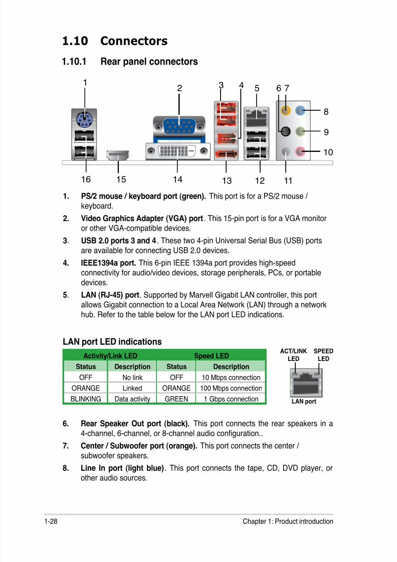
1.10.1 Rear panel connectors
1. PS/2 mouse / keyboard port (green). This port is for a PS/2 mouse /
keyboard.
2. Video Graphics Adapter (VGA) port. This 15-pin port is for a VGA monitor
or other VGA-compatible devices.
3. USB 2.0 ports 3 and 4. These two 4-pin Universal Serial Bus (USB) ports
are available for connecting USB 2.0 devices.
4. IEEE1394a port. This 6-pin IEEE 1394a port provides high-speed
connectivity for audio/video devices, storage peripherals, PCs, or portabledevices.
5. LAN (RJ-45) port. Supported by Marvell Gigabit LAN controller, this portallows Gigabit connection to a Local Area Network (LAN) through a network
hub. Refer to the table below for the LAN port LED indications.
Activity/Link LED Speed LED
Status Description Status Description
OFF No link OFF 10 Mbps connection
ORANGE Linked ORANGE 100 Mbps connection
BLINKING Data activity GREEN 1 Gbps connection
LAN port LED indicationsSPEED
LED
ACT/LINK
LED
LAN port
6
8
52 3 4 7
9
10
1112131415
1
16
6. Rear Speaker Out port (black). This port connects the rear speakers in a
4-channel, 6-channel, or 8-channel audio conguration..
7. Center / Subwoofer port (orange). This port connects the center /
subwoofer speakers.
8. Line In port (light blue). This port connects the tape, CD, DVD player, or
other audio sources.
8/12/2019 Asus P5QL-EM Manual
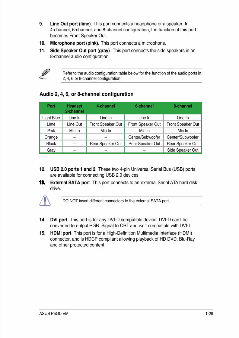
http://slidepdf.com/reader/full/asus-p5ql-em-manual 41/112
8/12/2019 Asus P5QL-EM Manual
http://slidepdf.com/reader/full/asus-p5ql-em-manual 42/112
1-30 Chapter 1: Product introduction
• This motherboard comes with dual-VGA output. If you connect 2 monitorsto both VGA and DVI-D / HDMI out ports, each controller can drive same ordifferent display contents to different resolutions and refresh rates.
• To play HD DVD or Blu-Ray Disc, ensure to use an HDCP compliant
monitor.
Playback of HD DVD and Blu-Ray Discs
The speed and bandwidth of the CPU/Memory, DVD player, and drivers
will affect the playback quality. Using the CPU/Memory of higher speed and
bandwidth with the higher-version DVD player and drivers will upgrade the
playback quality.
16. USB 2.0 ports 5 and 6. These two 4-pin Universal Serial Bus (USB) portsare available for connecting USB 2.0 devices.
8/12/2019 Asus P5QL-EM Manual
http://slidepdf.com/reader/full/asus-p5ql-em-manual 43/112
ASUS P5QL-EM 1-31
1.10.2 Internal connectors
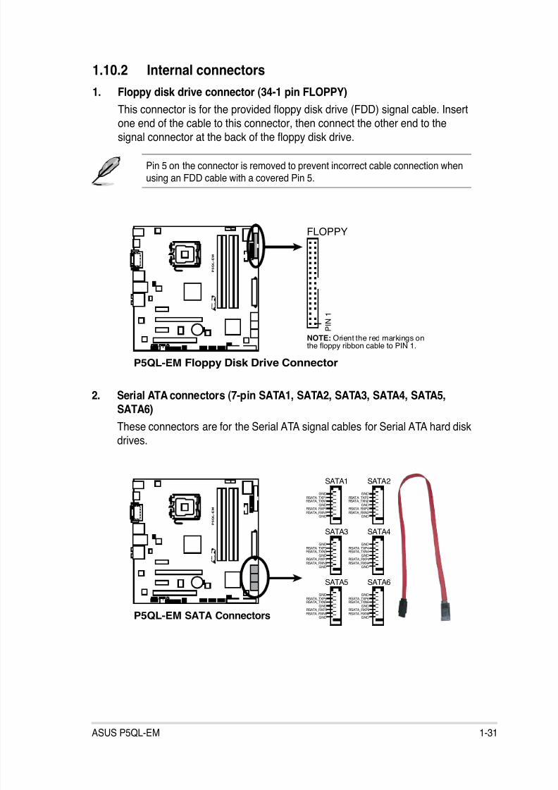
1. Floppy disk drive connector (34-1 pin FLOPPY)
This connector is for the provided oppy disk drive (FDD) signal cable. Insert
one end of the cable to this connector, then connect the other end to thesignal connector at the back of the oppy disk drive.
Pin 5 on the connector is removed to prevent incorrect cable connection whenusing an FDD cable with a covered Pin 5.
2. Serial ATA connectors (7-pin SATA1, SATA2, SATA3, SATA4, SATA5,SATA6)
These connectors are for the Serial ATA signal cables for Serial ATA hard disk
drives.
P5QL-EM Floppy Disk Drive Connector
P 5 Q L - E M
R
NOTE: Orient the red markings onthe floppy ribbon cable to PIN 1.
P I N 1
FLOPPY
P5QL-EM SATA Connectors
P 5 Q L - E M
R
GNDRSATA_TXP1RSATA_TXN1
GNDRSATA_RXP1RSATA_RXN1
GND
SATA1
GNDRSATA_TXP2RSATA_TXN2
GNDRSATA_RXP2RSATA_RXN2
GND
SATA2
GNDRSATA_TXP3RSATA_TXN3
GNDRSATA_RXP3RSATA_RXN3
GND
SATA3
GNDRSATA_TXP4RSATA_TXN4
GNDRSATA_RXP4RSATA_RXN4
GND
SATA4
GNDRSATA_TXP5RSATA_TXN5
GNDRSATA_RXP5RSATA_RXN5
GND
SATA5
GNDRSATA_TXP6RSATA_TXN6
GNDRSATA_RXP6RSATA_RXN6
GND
SATA6
8/12/2019 Asus P5QL-EM Manual
http://slidepdf.com/reader/full/asus-p5ql-em-manual 44/112
1-32 Chapter 1: Product introduction
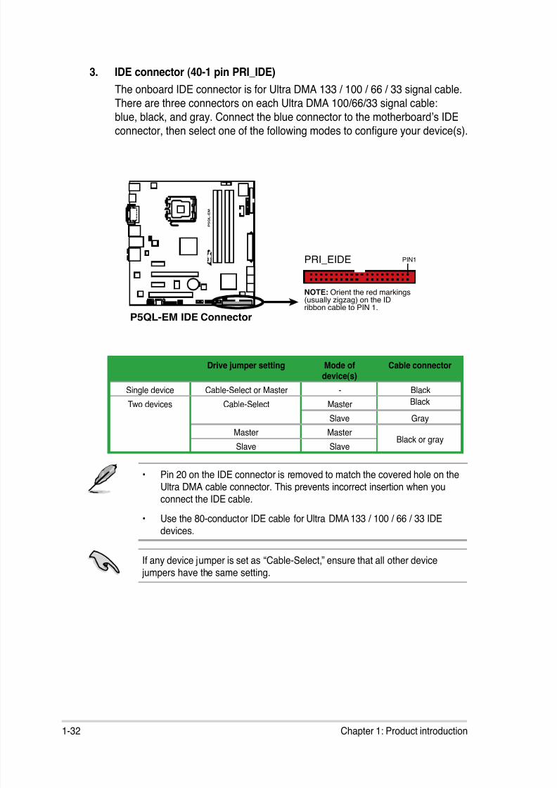
3. IDE connector (40-1 pin PRI_IDE)
The onboard IDE connector is for Ultra DMA 133 / 100 / 66 / 33 signal cable.
There are three connectors on each Ultra DMA 100/66/33 signal cable:
blue, black, and gray. Connect the blue connector to the motherboard’s IDE
connector, then select one of the following modes to congure your device(s).
• Pin 20 on the IDE connector is removed to match the covered hole on theUltra DMA cable connector. This prevents incorrect insertion when youconnect the IDE cable.
• Use the 80-conductor IDE cable for Ultra DMA 133 / 100 / 66 / 33 IDEdevices.
If any device jumper is set as “Cable-Select,” ensure that all other device jumpers have the same setting.
Drive jumper setting Mode of
device(s)
Cable connector
Single device Cable-Select or Master - Black
Two devices Cable-Select Master Black
Slave Gray
Master MasterBlack or gray
Slave Slave
P5QL-EM IDE Connector
P 5 Q L - E M
R
NOTE: Orient the red markings(usually zigzag) on the IDribbon cable to PIN 1.
PRI_EIDE PIN1
8/12/2019 Asus P5QL-EM Manual
http://slidepdf.com/reader/full/asus-p5ql-em-manual 45/112
ASUS P5QL-EM 1-33
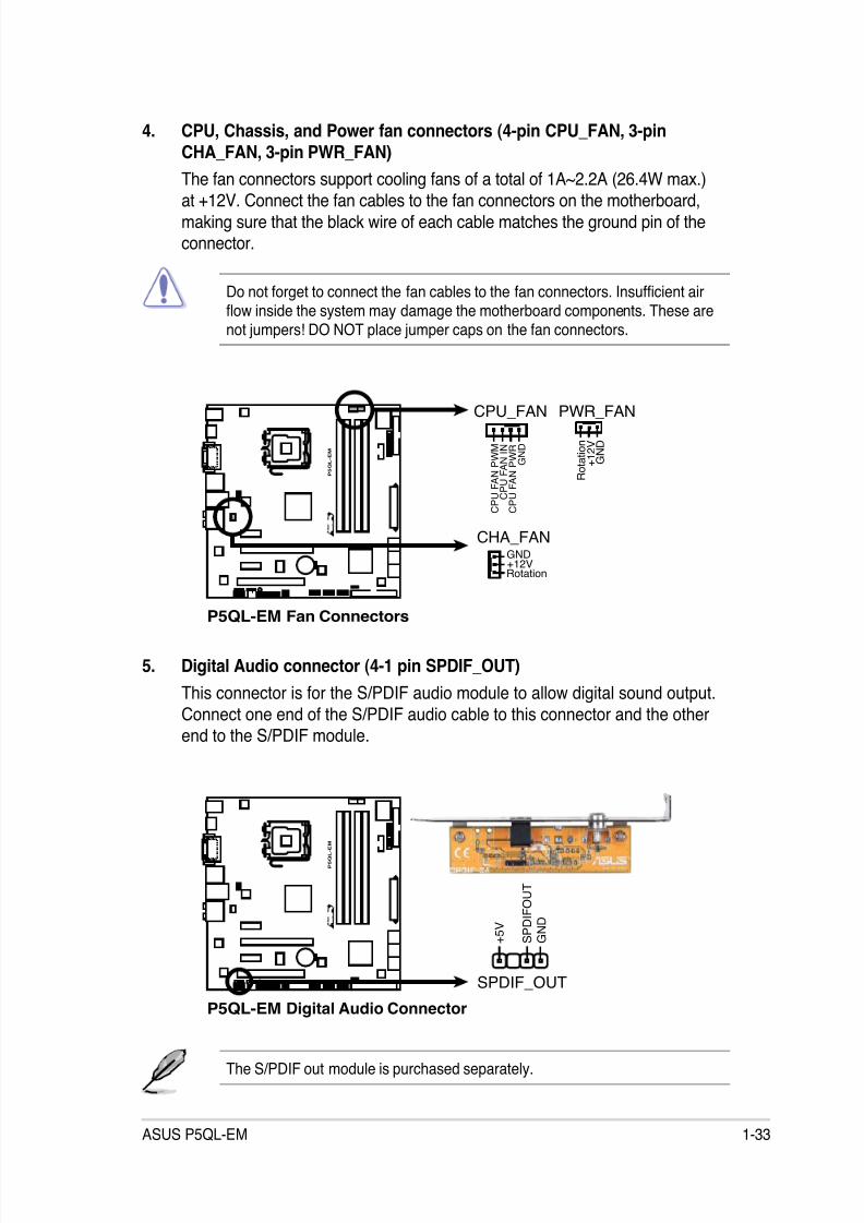
5. Digital Audio connector (4-1 pin SPDIF_OUT)
This connector is for the S/PDIF audio module to allow digital sound output.
Connect one end of the S/PDIF audio cable to this connector and the otherend to the S/PDIF module.
The S/PDIF out module is purchased separately.
4. CPU, Chassis, and Power fan connectors (4-pin CPU_FAN, 3-pinCHA_FAN, 3-pin PWR_FAN)
The fan connectors support cooling fans of a total of 1A~2.2A (26.4W max.)
at +12V. Connect the fan cables to the fan connectors on the motherboard,making sure that the black wire of each cable matches the ground pin of theconnector.
Do not forget to connect the fan cables to the fan connectors. Insufcient airow inside the system may damage the motherboard components. These arenot jumpers! DO NOT place jumper caps on the fan connectors.
P5QL-EM Fan Connectors
P 5 Q L - E M
R
CPU_FAN
G N D
C P U F A N P W R
C P U F A N I N
C P U F A N P W M
PWR_FAN
G N D
R o t a t i o n
+ 1 2 V
CHA_FANGND
Rotation+12V
P5QL-EM Digital Audio Connector
P 5 Q L - E M
R
+ 5 V
S P D I F O U T
G N D
SPDIF_OUT
8/12/2019 Asus P5QL-EM Manual
http://slidepdf.com/reader/full/asus-p5ql-em-manual 46/112
1-34 Chapter 1: Product introduction
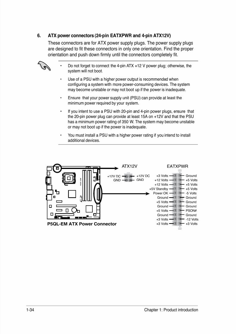
6. ATX power connectors (24-pin EATXPWR and 4-pin ATX12V)
These connectors are for ATX power supply plugs. The power supply plugs
are designed to t these connectors in only one orientation. Find the proper
orientation and push down rmly until the connectors completely t.
• Do not forget to connect the 4-pin ATX +12 V power plug; otherwise, thesystem will not boot.
• Use of a PSU with a higher power output is recommended whenconguring a system with more power-consuming devices. The system
may become unstable or may not boot up if the power is inadequate.
• Ensure that your power supply unit (PSU) can provide at least the
minimum power required by your system.
• If you intent to use a PSU with 20-pin and 4-pin power plugs, ensure thatthe 20-pin power plug can provide at least 15A on +12V and that the PSU
has a minimum power rating of 350 W. The system may become unstableor may not boot up if the power is inadequate.
• You must install a PSU with a higher power rating if you intend to installadditional devices.
P5QL-EM ATX Power Connector
P 5 Q L - E M
R
EATXPWR
+3 Volts
+3 VoltsGround
+5 Volts
+5 Volts
Ground
Ground
Power OK
+5V Standby
+12 Volts
-5 Volts
+5 Volts
+3 Volts
-12 VoltsGround
Ground
Ground
PSON#
Ground
+5 Volts
+12 Volts
+3 Volts
+5 Volts
Ground
ATX12V
GND+12V DC
GND+12V DC
8/12/2019 Asus P5QL-EM Manual
http://slidepdf.com/reader/full/asus-p5ql-em-manual 47/112

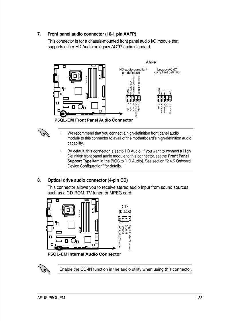
8/12/2019 Asus P5QL-EM Manual
http://slidepdf.com/reader/full/asus-p5ql-em-manual 48/112
1-36 Chapter 1: Product introduction
10. USB connectors (10-1 pin USB1112, USB910, USB78)
Never connect a 1394 cable to the USB connectors. Doing so will damage themotherboard!
The USB module is purchased separately.
9. Chassis intrusion connector (4-1 pin CHASSIS)
This connector is for a chassis-mounted intrusion detection sensor or switch.
Connect one end of the chassis intrusion sensor or switch cable to this
connector. The chassis intrusion sensor or switch sends a high-level signal tothis connector when a chassis component is removed or replaced. The signal
is then generated as a chassis intrusion event.
By default, the pins labeled “Chassis Signal” and “Ground” are shorted with
a jumper cap. Remove the jumper caps only when you intend to use the
chassis intrusion detection feature.
P 5
Q L - E M
R
P5QL-EM USB 2.0 Connectors
USB78 U S B + 5 V
U S B_
P 8 -
U S B_
P 8 +
G N D
N C
U S B + 5 V
U S B_
P 7 -
U S B_
P 7 +
G N D
1
USB910 U S B + 5 V
U S B_
P 1 0
-
U S B_
P 1 0
+
G N D
N C
U S B + 5 V
U S B_
P 9 -
U S B_
P 9 +
G N D
1
USB1112 U S B + 5 V
U S B_
P 1 2
-
U S B_
P 1 2
+
G N D
N C
U S B + 5 V
U S B_
P 1 1 -
U S B_
P 1 1 +
G N D
1
P5QL-EM Intrusion Connector
P 5 Q L - E M
R
CHASSIS
+ 5 V S B_
M B
C h a s s i s S i g n a l
G N D
(Default)
8/12/2019 Asus P5QL-EM Manual
http://slidepdf.com/reader/full/asus-p5ql-em-manual 49/112
ASUS P5QL-EM 1-37
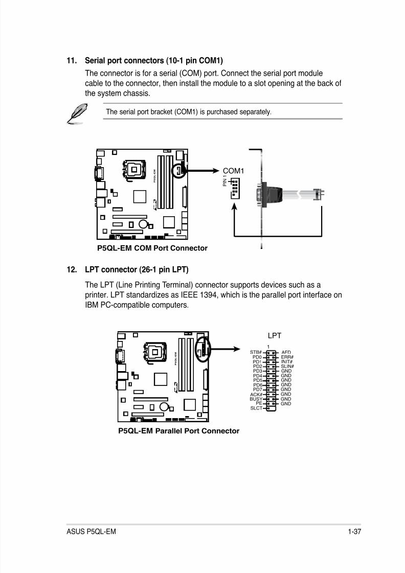
11. Serial port connectors (10-1 pin COM1)
The connector is for a serial (COM) port. Connect the serial port module
cable to the connector, then install the module to a slot opening at the back of
the system chassis.
The serial port bracket (COM1) is purchased separately.
12. LPT connector (26-1 pin LPT)
The LPT (Line Printing Terminal) connector supports devices such as a
printer. LPT standardizes as IEEE 1394, which is the parallel port interface on
IBM PC-compatible computers.
P5QL-EM COM Port Connector
P 5 Q L - E M
R
P I N 1COM1
P5QL-EM Parallel Port Connector
P 5 Q L - E M
R
LPT
STB# AFDPD0 ERR#PD1 INIT #
PD2 SLIN#PD3 GNDPD4
1
GND
PD7PD6PD5
GNDGND
GNDACK# GNDBUSY
PESLCT
GNDGND

8/12/2019 Asus P5QL-EM Manual
http://slidepdf.com/reader/full/asus-p5ql-em-manual 50/112
1-38 Chapter 1: Product introduction
13. System panel connector (20-8 pin F_PANEL)
This connector supports several chassis-mounted functions.
• System power LED (2-pin PLED)
This 2-pin connector is for the system power LED. Connect the chassis
power LED cable to this connector. The system power LED lights up whenyou turn on the system power, and blinks when the system is in sleep mode.
• Hard disk drive activity LED (2-pin IDE_LED)
This 2-pin connector is for the HDD Activity LED. Connect the HDD Activity
LED cable to this connector. The IDE LED lights up or ashes when data is
read from or written to the HDD.
• System warning speaker (4-pin SPEAKER)
This 4-pin connector is for the chassis-mounted system warning speaker. The
speaker allows you to hear system beeps and warnings.
• ATX power button/soft-off button (2-pin PWRSW)
This connector is for the system power button. Pressing the power buttonturns the system on or puts the system in sleep or soft-off mode depending
on the BIOS settings. Pressing the power switch for more than four seconds
while the system is ON turns the system OFF.
• Reset button (2-pin RESET)
This 2-pin connector is for the chassis-mounted reset button for system
reboot without turning off the system power.
P5QL-EM System Panel Connector
P 5 Q L - E M
R
* Requires an ATX power supply
NEL
P L E D -
P W R
+ 5 V
S p e a k e r
G r o u n d
RESET
G r o u n d
R e s e t
G r o u n d
G r o u n d
PWRSW
P L E D +
I D E_
L E D -
I D E_
L E D +
IDE_LED
PLED SPEAKER
PA
8/12/2019 Asus P5QL-EM Manual
http://slidepdf.com/reader/full/asus-p5ql-em-manual 51/112
ASUS P5QL-EM 2-1
2BIOS setup
This chapter tells how to change
the system settings through the BIOSSetup menus. Detailed descriptions
of the BIOS parameters are alsoprovided.
8/12/2019 Asus P5QL-EM Manual
http://slidepdf.com/reader/full/asus-p5ql-em-manual 52/112
2-2 Chapter 2: BIOS setup
2.1 Managing and updating your BIOS
The following utilities allow you to manage and update the motherboard BasicInput/Output System (BIOS) setup.
1. ASUS EZ Flash 2: Updates the BIOS in DOS mode using a oppy disk or aUSB ash disk.
2. ASUS AFUDOS: Updates the BIOS in DOS mode using a bootable oppydisk.
3. ASUS CrashFree BIOS 3: Updates the BIOS using a bootable oppy disk,
a USB ash disk or the motherboard support DVD when the BIOS le fails or
gets corrupted.
4. ASUS Update: Updates the BIOS in Windows® environment.
Refer to the corresponding sections for details on these utilities.
2.1.1 Creating a bootable oppy disk
1. Do either of the following to create a bootable oppy disk.
DOS environment
a. Insert a 1.44MB oppy disk into the drive.
b. At the DOS prompt, type format A:/S then press <Enter>.
Save a copy of the original motherboard BIOS le to a bootable oppy disk ora USB ash disk in case you need to restore the BIOS in the future. Copy theoriginal motherboard BIOS using the ASUS Update or AFUDOS utilities.
Windows ® XP environment
a. Insert a 1.44 MB oppy disk to the oppy disk drive.
b. Click Start from the Windows® desktop, then select My Computer.
c. Select the 3 1/2 Floppy Drive icon.
d. Click File from the menu, then select Format. A Format 3 1/2 FloppyDisk window appears.
e. Select Create an MS-DOS startup disk from the format options eld,
then click Start.
8/12/2019 Asus P5QL-EM Manual
http://slidepdf.com/reader/full/asus-p5ql-em-manual 53/112
ASUS P5QL-EM 2-3
Windows ® Vista environment
a. Insert a formatted, high density 1.44 MB oppy disk to the oppy disk
drive.
b. Click from the Windows® desktop, then select Computer.
c. Right-click Floppy Disk Drive then click Format to display the
Format 3 1/2 Floppy dialog box.
d. Select the Create an MS-DOS startup disk check box.
e. Click Start.
2. Copy the original or the latest motherboard BIOS le to the bootable oppy
disk.
8/12/2019 Asus P5QL-EM Manual
http://slidepdf.com/reader/full/asus-p5ql-em-manual 54/112
2-4 Chapter 2: BIOS setup
• This function can support devices such as USB ash disks, or oppy diskswith FAT 32/16 format and single partition only.
• DO NOT shut down or reset the system while updating the BIOS to preventsystem boot failure!
4. When the correct BIOS le is found, EZ Flash 2 performs the BIOS update
process and automatically reboots the system when done.
2.1.2 ASUS EZ Flash 2 utility
The ASUS EZ Flash 2 feature allows you to update the BIOS without having to go
through the long process of booting from a oppy disk and using a DOS-based
utility. The EZ Flash 2 utility is built-in the BIOS chip so it is accessible by pressing<Alt> + <F2> during the Power-On Self Tests (POST).
To update the BIOS using EZ Flash 2:
1. Visit the ASUS website (www.asus.com) to download the latest BIOS le for
the motherboard.
2. Save the BIOS le to a oppy disk or a USB ash disk, then restart the
system.
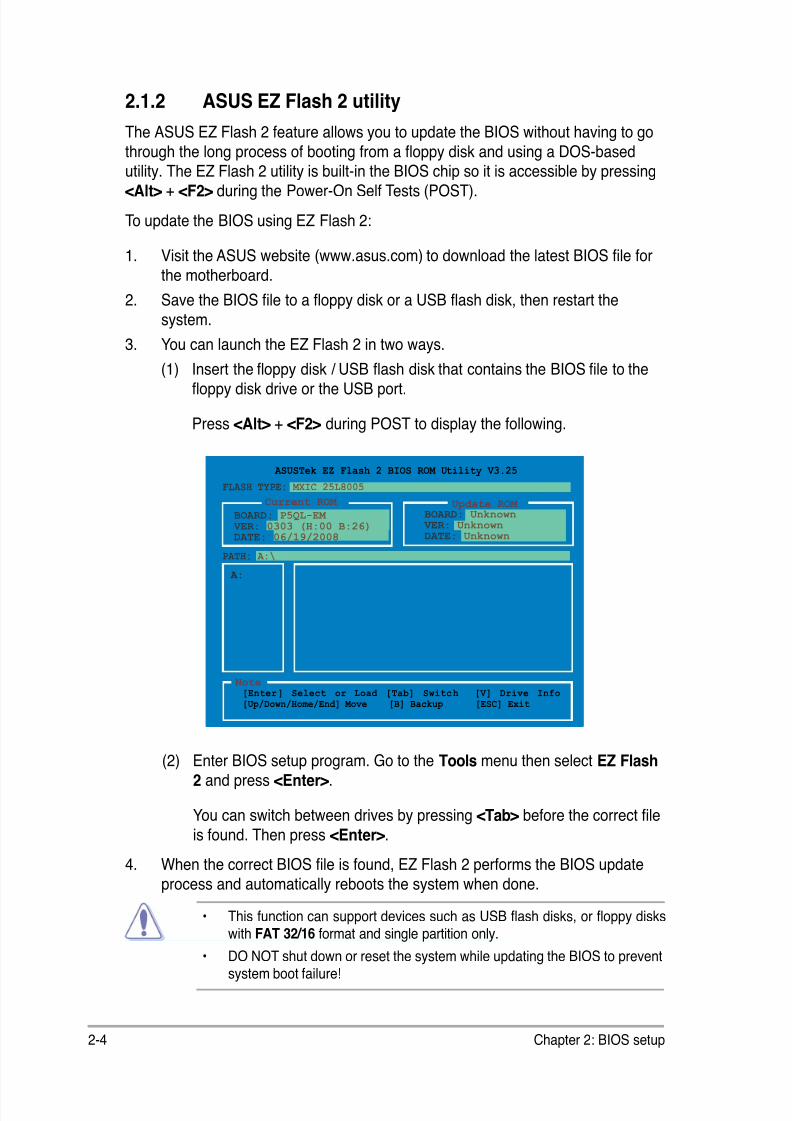
3. You can launch the EZ Flash 2 in two ways.
(1) Insert the oppy disk / USB ash disk that contains the BIOS le to the
oppy disk drive or the USB port.
Press <Alt> + <F2> during POST to display the following.
(2) Enter BIOS setup program. Go to the Tools menu then select EZ Flash2 and press <Enter>.
You can switch between drives by pressing <Tab> before the correct le
is found. Then press <Enter>.
ASUSTek EZ Flash 2 BIOS ROM Utility V3.25
Current ROM Update ROM
A:
Note [Enter] Select or Load [Tab] Switch [V] Drive Info
[Up/Down/Home/End] Move [B] Backup [ESC] Exit
FLASH TYPE: MXIC 25L8005
PATH: A:\
BOARD: P5QL-EM VER: 0303 (H:00 B:26)
DATE: 06/19/2008
BOARD: Unknown VER: Unknown
DATE: Unknown
8/12/2019 Asus P5QL-EM Manual
http://slidepdf.com/reader/full/asus-p5ql-em-manual 55/112
ASUS P5QL-EM 2-5
2.1.3 AFUDOS utility
The AFUDOS utility allows you to update the BIOS le in DOS environment using
a bootable oppy disk with the updated BIOS le. This utility also allows you to
copy the current BIOS le that you can use as backup when the BIOS fails or getscorrupted during the updating process.
Copying the current BIOS
To copy the current BIOS le using the AFUDOS utility:
1. Copy the AFUDOS utility (afudos.exe) from the motherboard support DVD to
the bootable oppy disk you created earlier.
2. Boot the system in DOS mode, then at the prompt type:
afudos /o[lename]
where the [lename] is any user-assigned lename not more than eight
alphanumeric characters for the main lename and three alphanumeric
characters for the extension name.
Main lename Extension name
A:\>afudos /oOLDBIOS1.rom
• Ensure that the oppy disk is not write-protected and has at least 1.2MBfree space to save the le.
• The succeeding BIOS screens are for reference only. The actual BIOS
screen displays may not be same as shown.
The utility returns to the DOS prompt after copying the current BIOS le.
3. Press <Enter>. The utility copies the current BIOS le to the oppy disk.
A:\>afudos /oOLDBIOS1.rom AMI Firmware Update Utility - Version 1.19(ASUS V2.07(03.11.24BB))Copyright (C) 2002 American Megatrends, Inc. All rights reserved. Reading ash ..... done Write to le...... ok A:\>
8/12/2019 Asus P5QL-EM Manual
http://slidepdf.com/reader/full/asus-p5ql-em-manual 56/112
2-6 Chapter 2: BIOS setup
Updating the BIOS le
To update the BIOS le using the AFUDOS utility:
1. Visit the ASUS website (www.asus.com) and download the latest BIOS le forthe motherboard. Save the BIOS le to a bootable oppy disk.
2. Copy the AFUDOS utility (afudos.exe) from the motherboard support DVD tothe bootable oppy disk you created earlier.
3. Boot the system in DOS mode, then at the prompt type:
afudos /i[lename]
where [lename] is the latest or the original BIOS le on the bootable oppy
disk.
A:\>afudos /iP5QLEM.ROM
Write the BIOS lename on a piece of paper. You need to type the exact BIOS
lename at the DOS prompt.
5. The utility returns to the DOS prompt after the BIOS update process is
completed. Reboot the system from the hard disk drive.
A:\>afudos /iP5QLEM.ROM AMI Firmware Update Utility - Version 1.19(ASUS V2.07(03.11.24BB))Copyright (C) 2002 American Megatrends, Inc. All rights reserved.
WARNING!! Do not turn off power during ash BIOS
Reading le ....... done Reading ash ...... done
Advance Check ...... Erasing ash ...... done Writing ash ...... done Verifying ash .... done
Please restart your computer
A:\>
A:\>afudos /iP5QLEM.ROM AMI Firmware Update Utility - Version 1.19(ASUS V2.07(03.11.24BB))Copyright (C) 2002 American Megatrends, Inc. All rights reserved.
WARNING!! Do not turn off power during ash BIOS Reading le ....... done Reading ash ...... done
Advance Check ...... Erasing ash ...... done Writing ash ...... 0x0008CC00 (9%)
4. The utility veries the le and starts updating the BIOS.
Do not shut down or reset the system while updating the BIOS to preventsystem boot failure!
8/12/2019 Asus P5QL-EM Manual
http://slidepdf.com/reader/full/asus-p5ql-em-manual 57/112
ASUS P5QL-EM 2-7
2.1.4 ASUS CrashFree BIOS 3 utility
The ASUS CrashFree BIOS 3 is an auto recovery tool that allows you to restore
the BIOS le when it fails or gets corrupted during the updating process. You canupdate a corrupted BIOS le using the motherboard support DVD , the oppy disk
or the USB ash disk that contains the updated BIOS le.
• Prepare the motherboard support DVD, the oppy disk or the USB ashdisk containing the updated motherboard BIOS before using this utility.
• Make sure that you rename the original or updated BIOS le in the oppydisk or the USB ash disk to P5QLEM.ROM.
Recovering the BIOS from a oppy diskTo recover the BIOS from a oppy disk:
1. Turn on the system.
2. Insert the oppy disk with the original or updated BIOS le to the oppy diskdrive.
3. The utility displays the following message and automatically checks theoppy disk for the original or updated BIOS le.
Bad BIOS checksum. Starting BIOS recovery...Checking for oppy...
When found, the utility reads the BIOS le and starts ashing the corrupted
BIOS le.
Bad BIOS checksum. Starting BIOS recovery...Checking for oppy...Floppy found!Reading le “P5QLEM.ROM”. Completed.
Start ashing...
DO NOT shut down or reset the system while updating the BIOS! Doing so cancause system boot failure!
4. Restart the system after the utility completes the updating process.
8/12/2019 Asus P5QL-EM Manual
http://slidepdf.com/reader/full/asus-p5ql-em-manual 58/112
2-8 Chapter 2: BIOS setup
Recovering the BIOS from the support DVD
To recover the BIOS from the support DVD:
1. Remove any oppy disk from the oppy disk drive, then turn on the system.2. Insert the support DVD to the optical drive.
3. The utility displays the following message and automatically checks theoppy disk for the original or updated BIOS le.
Bad BIOS checksum. Starting BIOS recovery...Checking for oppy...Floppy not found!Checking for CD-ROM...CD-ROM found!Reading le “P5QLEM.ROM”. Completed.Start ashing...
When no oppy disk is found, the utility automatically checks the optical drivefor the original or updated BIOS le. The utility then updates the corrupted
BIOS le.
Bad BIOS checksum. Starting BIOS recovery...Checking for oppy...
4. Restart the system after the utility completes the updating process.
The recovered BIOS may not be the latest BIOS version for this motherboard.Visit the ASUS website (www.asus.com) to download the latest BIOS le.
• Only the USB ash disk with FAT 32/16 format and single partition cansupport ASUS CrashFree BIOS 3. The device size should be smaller than8GB.
• DO NOT shut down or reset the system while updating the BIOS! Doing socan cause system boot failure!
Recovering the BIOS from the USB ash disk
To recover the BIOS from the USB ash disk:
1. Insert the USB ash disk that contains BIOS le to the USB port.
2. Turn on the system.
3. The utility will automatically checks the devices for the BIOS le When found,
the utility reads the BIOS le and starts ashing the corrupted BIOS le.
4. Restart the system after the utility completes the updating process.
8/12/2019 Asus P5QL-EM Manual
http://slidepdf.com/reader/full/asus-p5ql-em-manual 59/112
ASUS P5QL-EM 2-9
Installing ASUS Update
To install ASUS Update:
1. Place the support DVD in the optical drive. The Drivers menu appears.
2. Click the Utilities tab, then click Install ASUS Update. See page 3-4 for the
Utilities screen menu.
3. The ASUS Update utility is copied to your system.
2.1.5 ASUS Update utility
The ASUS Update is a utility that allows you to manage, save, and update the
motherboard BIOS in Windows® environment. The ASUS Update utility allows you
to: • Save the current BIOS le
• Download the latest BIOS le from the Internet
• Update the BIOS from an updated BIOS le
• Update the BIOS directly from the Internet, and
• View the BIOS version information.
This utility is available in the support DVD that comes with the motherboard
package.
ASUS Update requires an Internet connection either through a network or anInternet Service Provider (ISP).
Quit all Windows® applications before you update the BIOS using this utility.

8/12/2019 Asus P5QL-EM Manual
http://slidepdf.com/reader/full/asus-p5ql-em-manual 60/112
2-10 Chapter 2: BIOS setup
3. Select the ASUS FTP site nearest
you to avoid network trafc, or
click Auto Select. Click Next.
Updating the BIOS through the Internet
To update the BIOS through the Internet:
1. Launch the ASUS Update utility from the Windows® desktop by clicking Start> Programs > ASUS > ASUSUpdate > ASUSUpdate. The ASUS Update
main window appears.
2. Select Update BIOS fromthe Internet option from the
drop-down menu, then click Next.

8/12/2019 Asus P5QL-EM Manual
http://slidepdf.com/reader/full/asus-p5ql-em-manual 61/112
ASUS P5QL-EM 2-11
Updating the BIOS through a BIOS le
To update the BIOS through a BIOS le:
1. Launch the ASUS Update utility from the Windows® desktop by clicking Start> Programs > ASUS > ASUSUpdate > ASUSUpdate. The ASUS Update
main window appears.
2. Select Update BIOS from a le option from the drop-down menu,
then click Next.
4. From the FTP site, select the BIOS
version that you wish to download.
Click Next.
5. Follow the screen instructions tocomplete the update process.
The ASUS Update utility iscapable of updating itselfthrough the Internet. Alwaysupdate the utility to avail all itsfeatures.
3. Locate the BIOS le from the Open window, then click Open.
4. Follow the screen instructions to
complete the update process.
P5QL-EM
P5QL-EMROM
8/12/2019 Asus P5QL-EM Manual
http://slidepdf.com/reader/full/asus-p5ql-em-manual 62/112
2-12 Chapter 2: BIOS setup
• The default BIOS settings for this motherboard apply for most conditionsto ensure optimum performance. If the system becomes unstable afterchanging any BIOS settings, load the default settings to ensure systemcompatibility and stability. Select the Load Setup Defaults item under the
Exit Menu. See section “2.8 Exit Menu.”
• The BIOS setup screens shown in this section are for reference purposes only,and may not exactly match what you see on your screen.
• Visit the ASUS website (www.asus.com) to download the latest BIOS le
for this motherboard.
2.2 BIOS setup program
This motherboard supports a programmable rmware chip that you can updateusing the provided utility described in section “2.1 Managing and updating your
BIOS.”
Use the BIOS Setup program when you are installing a motherboard, reconguringyour system, or prompted to “Run Setup”. This section explains how to congure
your system using this utility.
Even if you are not prompted to use the Setup program, you can change the
conguration of your computer in the future. For example, you can enable the
security password feature or change the power management settings. This
requires you to recongure your system using the BIOS Setup program so that thecomputer can recognize these changes and record them in the CMOS RAM of the
SPI chip.
The rmware chip on the motherboard stores the Setup utility. When you start up
the computer, the system provides you with the opportunity to run this program.
Press <Del> during the Power-On Self-Test (POST) to enter the Setup utility;otherwise, POST continues with its test routines.
If you wish to enter Setup after POST, reboot the system by doing any of the
following procedures:
• Restart using the OS standard shut-down procedure.
• Press <Ctrl>+<Alt>+<Del> simultaneously.
• Press the reset button on the system chassis.
• Press the power button to turn the system off then back on.
Using the power button, reset button, or the <Ctrl>+<Alt>+<Del> keys toforce reset from a running operating system can cause damage to your dataor system. We recommend to always shut-down the system properly from theoperating system.
The Setup program is designed to make it as easy to use as possible. Being amenu-driven program, it lets you scroll through the various sub-menus and make
your selections from the available options using the navigation keys.
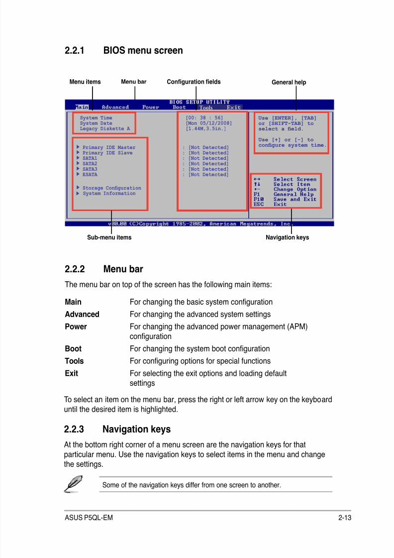
8/12/2019 Asus P5QL-EM Manual
http://slidepdf.com/reader/full/asus-p5ql-em-manual 63/112
ASUS P5QL-EM 2-13
2.2.2 Menu barThe menu bar on top of the screen has the following main items:
Main For changing the basic system conguration
Advanced For changing the advanced system settings
Power For changing the advanced power management (APM)
conguration
Boot For changing the system boot conguration
Tools For conguring options for special functions
Exit For selecting the exit options and loading defaultsettings
2.2.1 BIOS menu screen
To select an item on the menu bar, press the right or left arrow key on the keyboard
until the desired item is highlighted.
Some of the navigation keys differ from one screen to another.
2.2.3 Navigation keys
At the bottom right corner of a menu screen are the navigation keys for thatparticular menu. Use the navigation keys to select items in the menu and changethe settings.
Navigation keysSub-menu items
General helpMenu bar Conguration eldsMenu items
Use [ENTER], [TAB]or [SHIFT-TAB] toselect a eld.
Use [+] or [-] tocongure system time.
System Time [00: 38 : 56]System Date [Mon 05/12/2008]Legacy Diskette A [1.44M,3.5in.]
Primary IDE Master : [Not Detected]Primary IDE Slave : [Not Detected]SATA1 : [Not Detected]SATA2 : [Not Detected]SATA3 : [Not Detected]ESATA : [Not Detected]
Storage CongurationSystem Information
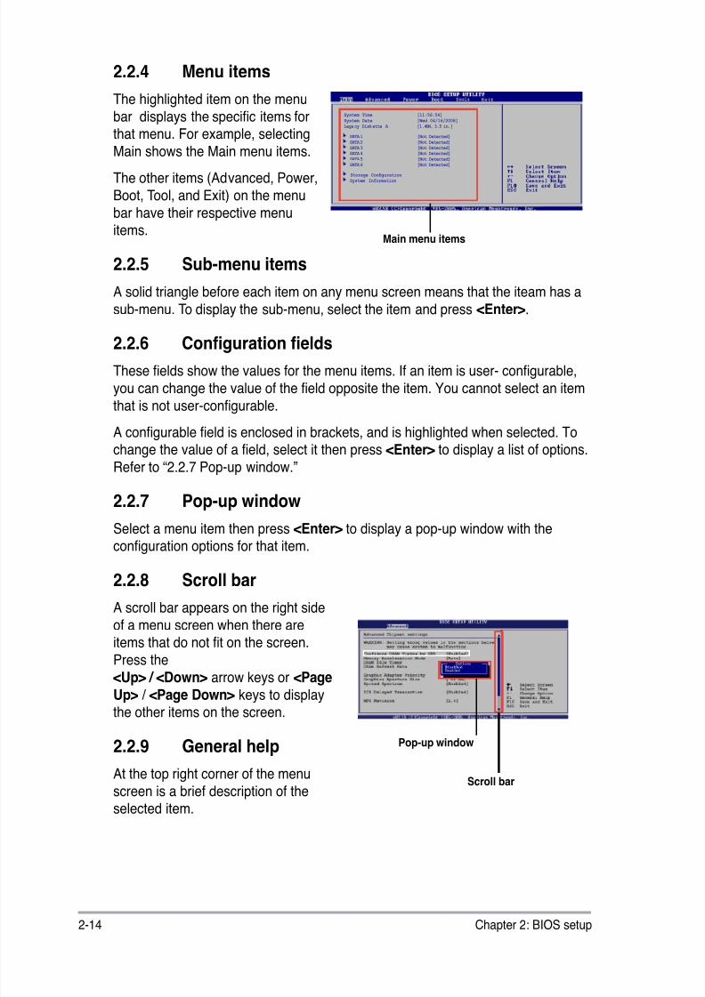
8/12/2019 Asus P5QL-EM Manual
http://slidepdf.com/reader/full/asus-p5ql-em-manual 64/112
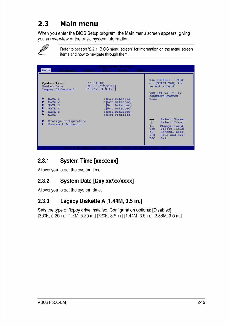
8/12/2019 Asus P5QL-EM Manual
http://slidepdf.com/reader/full/asus-p5ql-em-manual 65/112
ASUS P5QL-EM 2-15
2.3 Main menu
When you enter the BIOS Setup program, the Main menu screen appears, givingyou an overview of the basic system information.
2.3.1 System Time [xx:xx:xx]
Allows you to set the system time.
2.3.2 System Date [Day xx/xx/xxxx]
Allows you to set the system date.
2.3.3 Legacy Diskette A [1.44M, 3.5 in.]
Sets the type of oppy drive installed. Conguration options: [Disabled] [360K, 5.25 in.] [1.2M, 5.25 in.] [720K, 3.5 in.] [1.44M, 3.5 in.] [2.88M, 3.5 in.]
Refer to section “2.2.1 BIOS menu screen” for information on the menu screenitems and how to navigate through them.
Select Screen Select Item
+- Change Field Tab Select Field F1 General HelpF10 Save and ExitESC Exit
v02.58 (C)Copyright 1985-2008, American Megatrends, Inc.
BIOS SETUP UTILITY Main Advanced Power Boot Tools Exit
Use [ENTER], [TAB]or [SHIFT-TAB] toselect a eld.
Use [+] or [-] tocongure systemTime.
System Time [19:34:30]System Date [Mon 05/12/2008]Legacy Diskette A [1.44M, 3.5 in.]
SATA 1 :[Not Detected]SATA 2 :[Not Detected]SATA 3 :[Not Detected]
SATA 4 :[Not Detected] SATA 5 :[Not Detected] SATA :[Not Detected]
Storage Conguration System Information
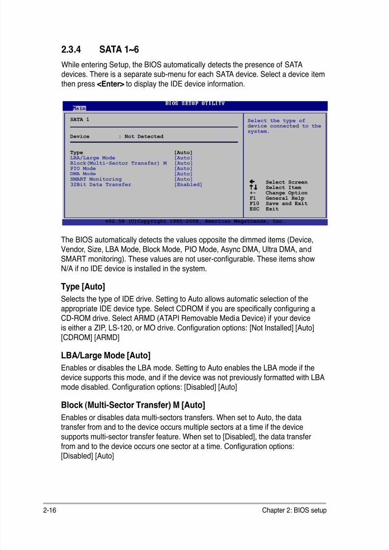
8/12/2019 Asus P5QL-EM Manual
http://slidepdf.com/reader/full/asus-p5ql-em-manual 66/112
2-16 Chapter 2: BIOS setup
2.3.4 SATA 1~6
While entering Setup, the BIOS automatically detects the presence of SATAdevices. There is a separate sub-menu for each SATA device. Select a device item
then press <Enter> to display the IDE device information.
The BIOS automatically detects the values opposite the dimmed items (Device,Vendor, Size, LBA Mode, Block Mode, PIO Mode, Async DMA, Ultra DMA, and
SMART monitoring). These values are not user-congurable. These items show
N/A if no IDE device is installed in the system.
Type [Auto]
Selects the type of IDE drive. Setting to Auto allows automatic selection of the
appropriate IDE device type. Select CDROM if you are specically conguring aCD-ROM drive. Select ARMD (ATAPI Removable Media Device) if your device
is either a ZIP, LS-120, or MO drive. Conguration options: [Not Installed] [Auto]
[CDROM] [ARMD]
LBA/Large Mode [Auto]
Enables or disables the LBA mode. Setting to Auto enables the LBA mode if the
device supports this mode, and if the device was not previously formatted with LBAmode disabled. Conguration options: [Disabled] [Auto]
Block (Multi-Sector Transfer) M [Auto]
Enables or disables data multi-sectors transfers. When set to Auto, the datatransfer from and to the device occurs multiple sectors at a time if the device
supports multi-sector transfer feature. When set to [Disabled], the data transferfrom and to the device occurs one sector at a time. Conguration options:[Disabled] [Auto]
Select Screen Select Item +- Change OptionF1 General HelpF10 Save and ExitESC Exit
SATA 1
Device : Not Detected
Type [Auto]LBA/Large Mode [Auto]Block(Multi-Sector Transfer) M [Auto]PIO Mode [Auto]
DMA Mode [Auto]SMART Monitoring [Auto]32Bit Data Transfer [Enabled]
Select the type ofdevice connected to thesystem.
v02.58 (C)Copyright 1985-2008, American Megatrends, Inc.
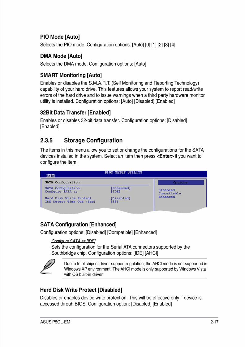
8/12/2019 Asus P5QL-EM Manual
http://slidepdf.com/reader/full/asus-p5ql-em-manual 67/112
ASUS P5QL-EM 2-17
PIO Mode [Auto]
Selects the PIO mode. Conguration options: [Auto] [0] [1] [2] [3] [4]
DMA Mode [Auto]Selects the DMA mode. Conguration options: [Auto]
SMART Monitoring [Auto]
Enables or disables the S.M.A.R.T. (Self Monitoring and Reporting Technology)
capability of your hard drive. This features allows your system to report read/write
errors of the hard drive and to issue warnings when a third party hardware monitorutility is installed. Conguration options: [Auto] [Disabled] [Enabled]
32Bit Data Transfer [Enabled]Enables or disables 32-bit data transfer. Conguration options: [Disabled]
[Enabled]
SATA Conguration [Enhanced]
Conguration options: [Disabled] [Compatible] [Enhanced]
Configure SATA as [IDE]
Sets the conguration for the Serial ATA connectors supported by the
Southbridge chip. Conguration options: [IDE] [AHCI]
2.3.5 Storage Conguration
The items in this menu allow you to set or change the congurations for the SATA
devices installed in the system. Select an item then press <Enter> if you want tocongure the item.
SATA Conguration
SATA Conguration [Enhanced]Congure SATA as [IDE]
Hard Disk Write Protect [Disabled]IDE Detect Time Out (Sec) [35]
Options
Disabled CompatiableEnhanced
Hard Disk Write Protect [Disabled]
Disables or enables device write protection. This will be effective only if device is
accessed throuh BIOS. Conguration option: [Disabled] [Enabled]
Due to Intel chipset driver support regulation, the AHCI mode is not supported inWindows XP environment. The AHCI mode is only supported by Windows Vistawith OS built-in driver.
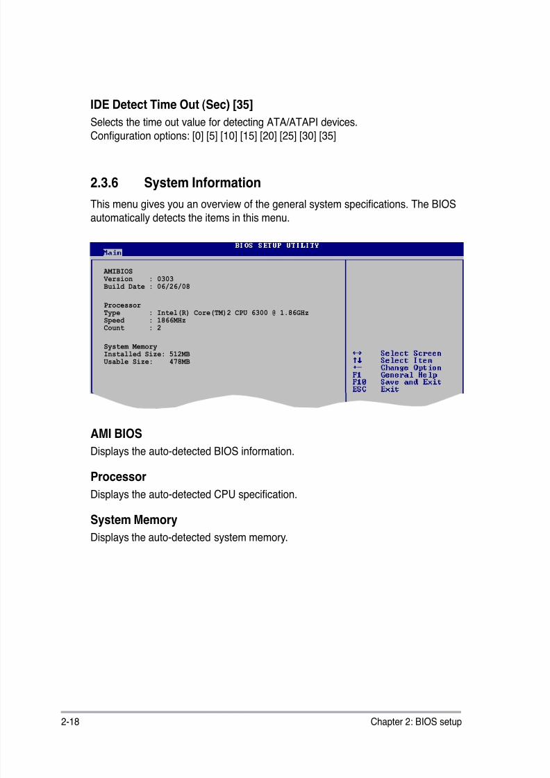
8/12/2019 Asus P5QL-EM Manual
http://slidepdf.com/reader/full/asus-p5ql-em-manual 68/112
2-18 Chapter 2: BIOS setup
2.3.6 System Information
This menu gives you an overview of the general system specications. The BIOS
automatically detects the items in this menu.
AMI BIOS
Displays the auto-detected BIOS information.
Processor
Displays the auto-detected CPU specication.
System Memory
Displays the auto-detected system memory.
AMIBIOS Version : 0303Build Date : 06/26/08
ProcessorType : Intel(R) Core(TM)2 CPU 6300 @ 1.86GHzSpeed : 1866MHzCount : 2
System MemoryInstalled Size: 512MB Usable Size: 478MB
IDE Detect Time Out (Sec) [35]
Selects the time out value for detecting ATA/ATAPI devices.Conguration options: [0] [5] [10] [15] [20] [25] [30] [35]

8/12/2019 Asus P5QL-EM Manual
http://slidepdf.com/reader/full/asus-p5ql-em-manual 69/112
ASUS P5QL-EM 2-19
2.4.1 JumperFree Conguration
AI Overclocking [Auto]
Allows selection of CPU overclocking options to achieve desired CPU internal
frequency. Select either one of the preset overclocking conguration options:
Manual - allows you to individually set overclocking parameters.
Auto - loads the optimal settings for the system.
Overclock Prole - loads overclocking proles with optimal parameters for
stability when overclocking.
Congure System Frequency/Voltage
AI Overclocking [Auto]DRAM Frequency [Auto]
Memory Over Voltage [Auto] NB Voltage [Auto]CPU Voltage [Auto]
Select the target CPUfrequency, and therelevant parameters will be auto-adjusted.Frequencies higherthan CPU manufacturerrecommends are notguaranteed to bestable. If the system becomes unstable,return to thedefault.
v02.58 (C)Copyright 1985-2008, American Megatrends, Inc.
BIOS SETUP UTILITY Main Advanced Power Boot Tools Exit
JumperFree Conguration CPU Conguration Chipset Onboard Devices Conguration USB Conguration PCIPnP
Select Screen Select Item
+- Change Field Tab Select Field F1 General HelpF10 Save and ExitESC Exit
Adjust Systemfrequency/voltage.
2.4 Advanced menu
The Advanced menu items allow you to change the settings for the CPU and other
system devices.
Take caution when changing the settings of the Advanced menu items. Incorrecteld values can cause the system to malfunction.
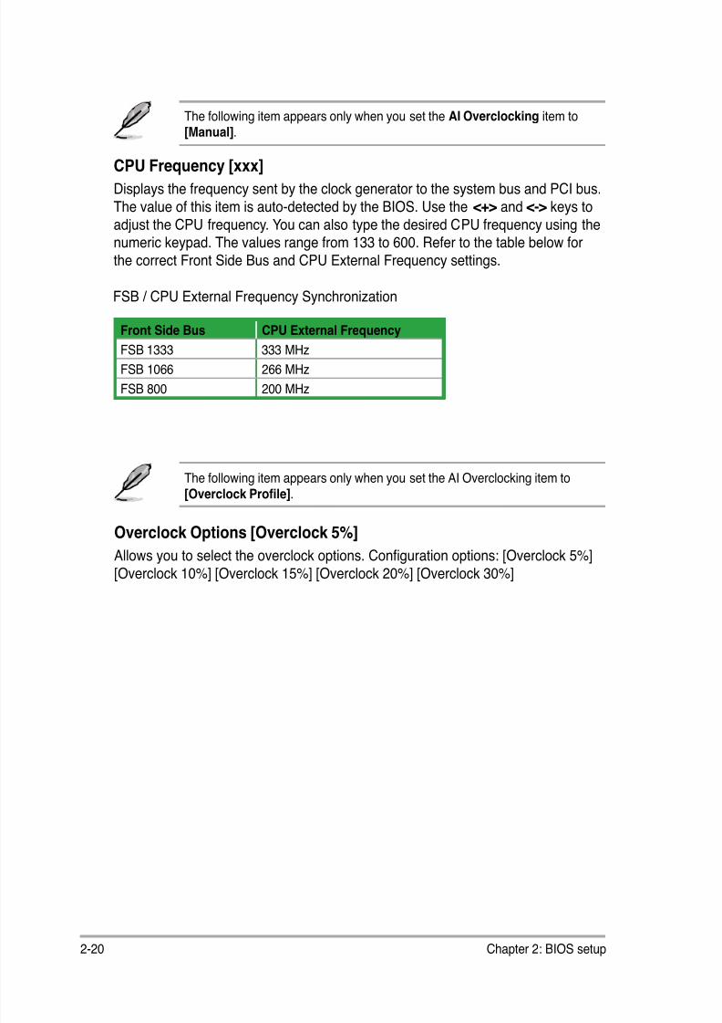
8/12/2019 Asus P5QL-EM Manual
http://slidepdf.com/reader/full/asus-p5ql-em-manual 70/112
2-20 Chapter 2: BIOS setup
FSB / CPU External Frequency Synchronization
CPU Frequency [xxx]Displays the frequency sent by the clock generator to the system bus and PCI bus.
The value of this item is auto-detected by the BIOS. Use the <+> and <-> keys to
adjust the CPU frequency. You can also type the desired CPU frequency using thenumeric keypad. The values range from 133 to 600. Refer to the table below for
the correct Front Side Bus and CPU External Frequency settings.
Overclock Options [Overclock 5%]
Allows you to select the overclock options. Conguration options: [Overclock 5%]
[Overclock 10%] [Overclock 15%] [Overclock 20%] [Overclock 30%]
The following item appears only when you set the AI Overclocking item to
[Overclock Prole].
Front Side Bus CPU External Frequency
FSB 1333 333 MHz
FSB 1066 266 MHz
FSB 800 200 MHz
The following item appears only when you set the AI Overclocking item to[Manual].

8/12/2019 Asus P5QL-EM Manual
http://slidepdf.com/reader/full/asus-p5ql-em-manual 71/112
ASUS P5QL-EM 2-21
Memory Over Voltage [Auto]
Allows you to adjust Memory Over voltage and each step is 6.25mV
NB Voltage [Auto]
Allows you to set the NB voltage. Conguration options: [Auto] [1.1V] [1.198V]
[1.3V] [1.388V]
Selecting a very high DRAM frequency may cause the system to becomeunstable! If this happens, revert to the default setting.
FSBDRAM Frequency
Auto 667MHz 800MHz 960MHz 1000MHz 1067MHz 1100MHz 1200MHz
1333 v v v v v
1066 v v v v
800 v v v
The following table shows the DRAM Frequency options that appear when theFSB value is 1333, 1066, and 800.
DRAM Frequency [Auto]
Allows you to set the DDR2 operating frequency. Conguration options: [Auto]
[667 MHz] [800 MHz] [1067MHz]
CPU Voltage [Auto]
Allows you to set the CPU VCore voltage. The values range from 0.8500V to 1.55V
with a 0.00625V interval. Conguration options: [Auto]
Setting a very high voltage may damage the component permanently, andsetting a very low voltage may cause the system to become unstable.
Setting a very high voltage may damage the component permanently, andsetting a very low voltage may cause the system to become unstable.

8/12/2019 Asus P5QL-EM Manual
http://slidepdf.com/reader/full/asus-p5ql-em-manual 72/112
2-22 Chapter 2: BIOS setup
2.4.2 CPU Conguration
The items in this menu show the CPU-related information that the BIOSautomatically detects.
CPU Ratio Setting [Auto]
Sets the ratio between CPU Core Clock and the FSB frequency. Conguration
options: [Auto].
C1E Support [Enabled]
Allows you to enable or disable Inter CPU Enhanced Halt (C1E) function, a
CPU power-saving function in system halt state. When enabled, the CPU core
frequency and voltage will be reduced during the system halt state to decreasepower consumption. Conguration options: [Disabled] [Enabled]
Max CPUID Value Limit [Disabled]
Allows you to determine whether to limit CPUID maximum value. Set this item to
[Disabled] for Windows XP operating system; set this item to [Enabled] for legacy
operating system such as Windows NT4.0. (Default: Disabled)
Conguration options: [Disabled] [Enabled]
v02.58 (C)Copyright 1985-2008, American Megatrends, Inc.
Congure advanced CPU settings Module Version: 3D.06
Manufacturer: IntelBrand String: Intel(R) Core(TM)2 CPU 6300 @ 1.86GHzFrequency: 1.86GHzFSB Speed: 1066MHzCache L1: 64 KBCache L2: 2048 KBRatio Status: Unlocked (Max:07.0, Min:06.0)Ratio Actual Value:7
CPUID: 6F2
CPU Ratio Setting [Auto]C1E Support [Enabled] Max CPUID Value Limit [Disabled] Vanderpool Technology [Enabled]CPU TM function [Enabled]Execute Disable Bit [Enabled]Intel(R) SpeedStep(tm) tech. [Enabled]
Sets the ratio betweenCPU Core Clock and theFSB Frequency. NOTE: If an invalidratio is set in CMOSthen actual andsetpoint values maydiffer. NOTE:Please Key in rationumbers directly!
BIOS SETUP UTILITY Advanced
If an invalid ratio is set in CMOS then actual and setpoint values my differ.
Key in ratio numbers directly.
8/12/2019 Asus P5QL-EM Manual
http://slidepdf.com/reader/full/asus-p5ql-em-manual 73/112
ASUS P5QL-EM 2-23
Intel® SpeedStep™ Technology [Enabled]
Allows you to use the Enhanced Intel® SpeedStep® Technology. When set to
[Enabled], you can adjust the system power settings in the operating system to
use the EIST feature. Set this item to [Disabled] if you do not want to use the
EIST. Conguration options: [Enabled] [Disabled]
The following item appears only when you installed an Intel® Pentium® 4 or laterCPU that supports the Enhanced Intel SpeedStep® Technology (EIST).
Vanderpool Technology [Enabled]
Enables or disables Intel® Virtualization Technology. Virtualization enhanced by
Intel® Virtualization Technology allows a platform to run multiple operating systems
and applications in independent partitons. With virtualization, one computer
system can function as multiple virtual systems. Conguration options: [Enabled][Disabled]
CPU TM function [Enabled]
Enables or disables Intel® CPU Thermal Monitor (TM) function, a CPU overheating
protection function. When enabled, the CPU core frequency and voltage are
reduced when the CPU overheats. Conguration options: [Disabled] [Enabled]
Execute Disable Bit [Enabled]
Enables or disables Intel® Execute Disable Bit function. This function enhance
protection of your computer, reducing exposure to viruses and maliciousbuffer overow attacks when working with its supporting software and system.
Conguration options: [Disabled] [Enabled]
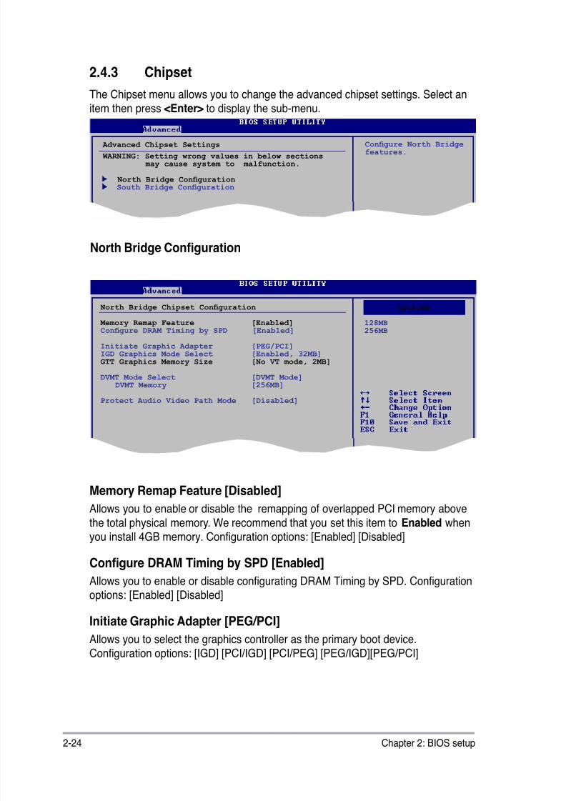
8/12/2019 Asus P5QL-EM Manual
http://slidepdf.com/reader/full/asus-p5ql-em-manual 74/112
2-24 Chapter 2: BIOS setup
2.4.3 Chipset
The Chipset menu allows you to change the advanced chipset settings. Select an
item then press <Enter> to display the sub-menu.
Advanced Chipset Settings
WARNING: Setting wrong values in below sections may cause system to malfunction.
North Bridge Conguration South Bridge Conguration
Congure North Bridge features.
North Bridge Conguration
North Bridge Chipset Conguration
Memory Remap Feature [Enabled]Congure DRAM Timing by SPD [Enabled]
Initiate Graphic Adapter [PEG/PCI]IGD Graphics Mode Select [Enabled, 32MB]GTT Graphics Memory Size [No VT mode, 2MB]
DVMT Mode Select [DVMT Mode]
DVMT Memory [256MB]
Protect Audio Video Path Mode [Disabled]
Options
128MB256MB
Options
Memory Remap Feature [Disabled]
Allows you to enable or disable the remapping of overlapped PCI memory abovethe total physical memory. We recommend that you set this item to Enabled when
you install 4GB memory. Conguration options: [Enabled] [Disabled]
Congure DRAM Timing by SPD [Enabled]
Allows you to enable or disable congurating DRAM Timing by SPD. Congurationoptions: [Enabled] [Disabled]
Initiate Graphic Adapter [PEG/PCI]
Allows you to select the graphics controller as the primary boot device.Conguration options: [IGD] [PCI/IGD] [PCI/PEG] [PEG/IGD][PEG/PCI]
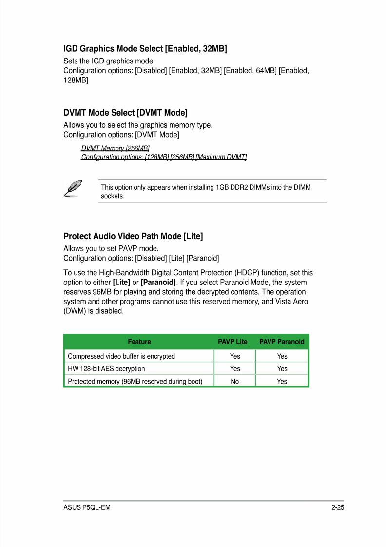
8/12/2019 Asus P5QL-EM Manual
http://slidepdf.com/reader/full/asus-p5ql-em-manual 75/112
ASUS P5QL-EM 2-25
DVMT Mode Select [DVMT Mode]
Allows you to select the graphics memory type.Conguration options: [DVMT Mode]
DVMT Memory [256MB] Configuration options: [128MB] [256MB] [Maximum DVMT]
Protect Audio Video Path Mode [Lite]
Allows you to set PAVP mode.
Conguration options: [Disabled] [Lite] [Paranoid]
To use the High-Bandwidth Digital Content Protection (HDCP) function, set this
option to either [Lite] or [Paranoid]. If you select Paranoid Mode, the system
reserves 96MB for playing and storing the decrypted contents. The operationsystem and other programs cannot use this reserved memory, and Vista Aero
(DWM) is disabled.
This option only appears when installing 1GB DDR2 DIMMs into the DIMMsockets.
Feature PAVP Lite PAVP Paranoid
Compressed video buffer is encrypted Yes Yes
HW 128-bit AES decryption Yes Yes
Protected memory (96MB reserved during boot) No Yes
IGD Graphics Mode Select [Enabled, 32MB]
Sets the IGD graphics mode.
Conguration options: [Disabled] [Enabled, 32MB] [Enabled, 64MB] [Enabled,
128MB]
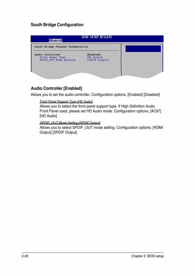
8/12/2019 Asus P5QL-EM Manual
http://slidepdf.com/reader/full/asus-p5ql-em-manual 76/112
2-26 Chapter 2: BIOS setup
South Bridge Conguration
Audio Controller [Enabled]Allows you to set the audio controller. Conguration options: [Enabled] [Disabled]
Front Panel Support Type [HD Audio]
Allows you to select the front panel support type. If High Denition Audio
Front Panel used, please set HD Audio mode. Conguration options: [AC97]
[HD Audio]
SPDIF_OUT Mode Setting [SPDIF Output]
Allows you to select SPDIF_OUT mode setting. Conguration options: [HDMI
Output] [SPDIF Output]
Options
South Bridge Chipset Conguration
Audio Controller [Enabled]
Front Panel Type [HD Audio] SPDIF_OUT Mode Setting [SPDIF Output]
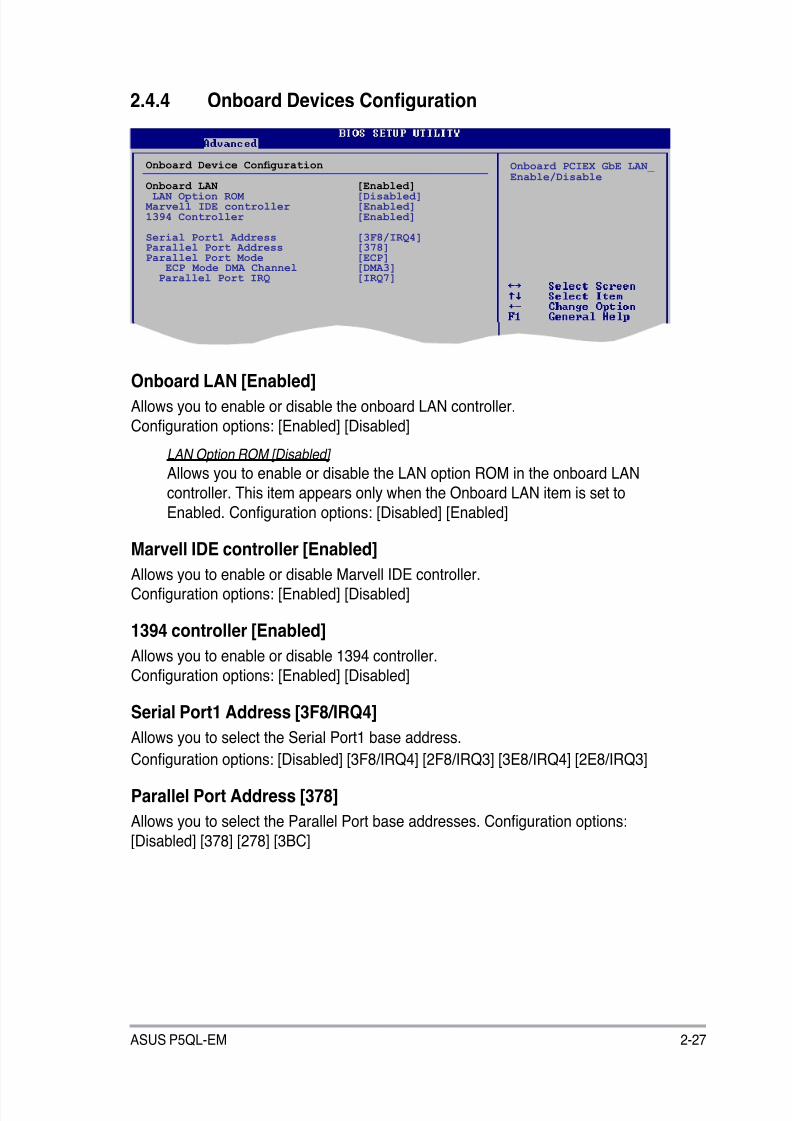
8/12/2019 Asus P5QL-EM Manual
http://slidepdf.com/reader/full/asus-p5ql-em-manual 77/112
ASUS P5QL-EM 2-27
2.4.4 Onboard Devices Conguration
Onboard LAN [Enabled]
Allows you to enable or disable the onboard LAN controller.
Conguration options: [Enabled] [Disabled]
LAN Option ROM [Disabled]
Allows you to enable or disable the LAN option ROM in the onboard LAN
controller. This item appears only when the Onboard LAN item is set to
Enabled. Conguration options: [Disabled] [Enabled]
Marvell IDE controller [Enabled]
Allows you to enable or disable Marvell IDE controller.Conguration options: [Enabled] [Disabled]
1394 controller [Enabled]
Allows you to enable or disable 1394 controller.
Conguration options: [Enabled] [Disabled]
Serial Port1 Address [3F8/IRQ4]Allows you to select the Serial Port1 base address.
Conguration options: [Disabled] [3F8/IRQ4] [2F8/IRQ3] [3E8/IRQ4] [2E8/IRQ3]
Parallel Port Address [378]
Allows you to select the Parallel Port base addresses. Conguration options:
[Disabled] [378] [278] [3BC]
Onboard Device Conguration
Onboard LAN [Enabled] LAN Option ROM [Disabled] Marvell IDE controller [Enabled]1394 Controller [Enabled]
Serial Port1 Address [3F8/IRQ4]Parallel Port Address [378]Parallel Port Mode [ECP] ECP Mode DMA Channel [DMA3] Parallel Port IRQ [IRQ7]
Onboard PCIEX GbE LAN_
Enable/Disable
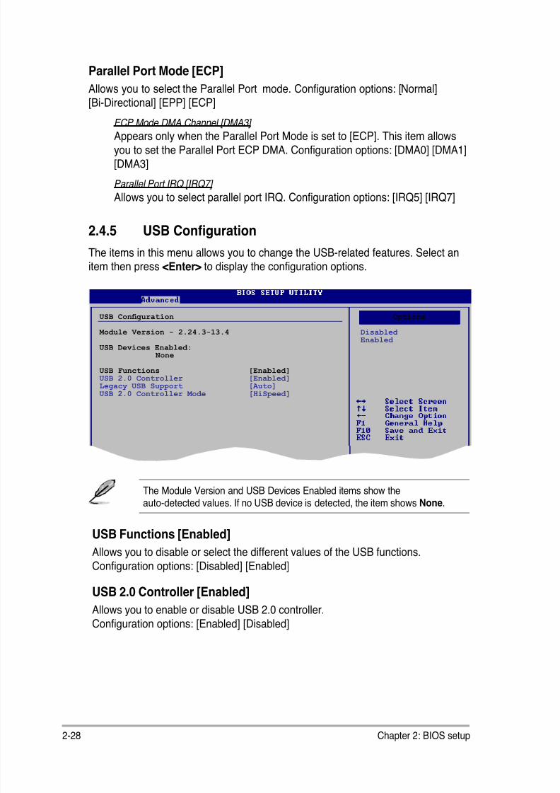
8/12/2019 Asus P5QL-EM Manual
http://slidepdf.com/reader/full/asus-p5ql-em-manual 78/112
2-28 Chapter 2: BIOS setup
The Module Version and USB Devices Enabled items show the
auto-detected values. If no USB device is detected, the item showsNone
.
2.4.5 USB Conguration
The items in this menu allows you to change the USB-related features. Select anitem then press <Enter> to display the conguration options.
USB Conguration
Module Version - 2.24.3-13.4
USB Devices Enabled: None
USB Functions [Enabled]
USB 2.0 Controller [Enabled]Legacy USB Support [Auto]USB 2.0 Controller Mode [HiSpeed]
Options
Disabled Enabled
Options
USB Functions [Enabled]
Allows you to disable or select the different values of the USB functions.
Conguration options: [Disabled] [Enabled]
USB 2.0 Controller [Enabled]
Allows you to enable or disable USB 2.0 controller.
Conguration options: [Enabled] [Disabled]
Parallel Port Mode [ECP]
Allows you to select the Parallel Port mode. Conguration options: [Normal]
[Bi-Directional] [EPP] [ECP]
ECP Mode DMA Channel [DMA3] Appears only when the Parallel Port Mode is set to [ECP]. This item allows
you to set the Parallel Port ECP DMA. Conguration options: [DMA0] [DMA1]
[DMA3]
Parallel Port IRQ [IRQ7]
Allows you to select parallel port IRQ. Conguration options: [IRQ5] [IRQ7]
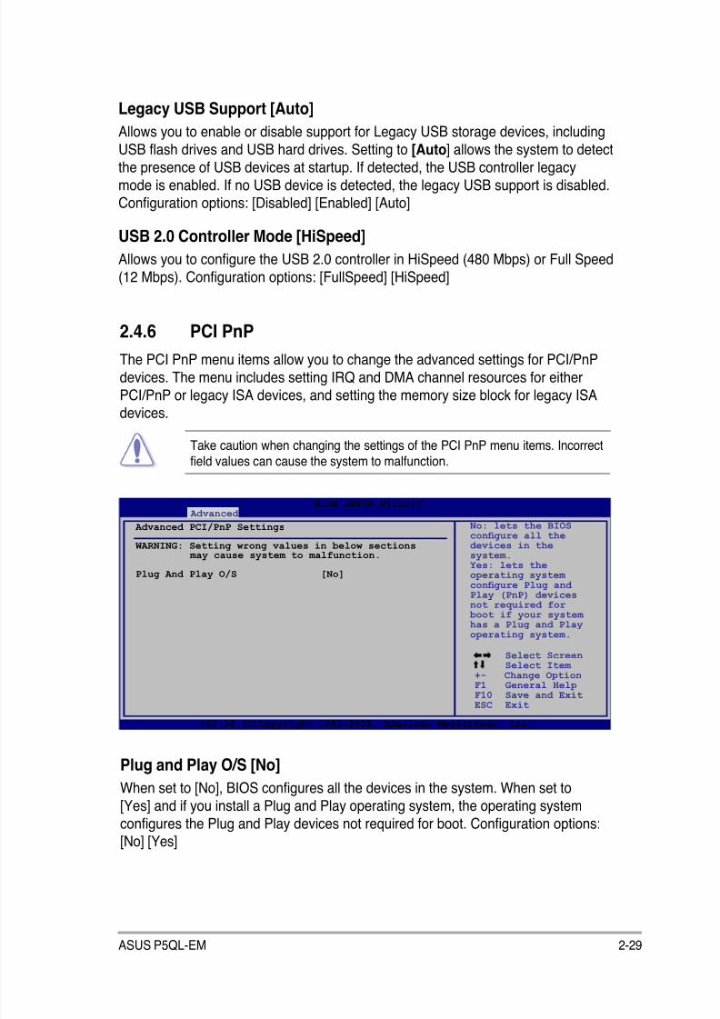
8/12/2019 Asus P5QL-EM Manual
http://slidepdf.com/reader/full/asus-p5ql-em-manual 79/112
ASUS P5QL-EM 2-29
2.4.6 PCI PnP
The PCI PnP menu items allow you to change the advanced settings for PCI/PnP
devices. The menu includes setting IRQ and DMA channel resources for either
PCI/PnP or legacy ISA devices, and setting the memory size block for legacy ISAdevices.
Take caution when changing the settings of the PCI PnP menu items. Incorrecteld values can cause the system to malfunction.
Plug and Play O/S [No]
When set to [No], BIOS congures all the devices in the system. When set to
[Yes] and if you install a Plug and Play operating system, the operating system
congures the Plug and Play devices not required for boot. Conguration options:[No] [Yes]
Select Screen Select Item
+- Change OptionF1 General HelpF10 Save and ExitESC Exit
v02.58 (C)Copyright 1985-2008, American Megatrends, Inc.
BIOS SETUP UTILITY Advanced
Advanced PCI/PnP Settings
WARNING: Setting wrong values in below sections may cause system to malfunction.
Plug And Play O/S [No]
No: lets the BIOScongure all thedevices in thesystem.Yes: lets theoperating systemcongure Plug andPlay (PnP) devicesnot required for boot if your systemhas a Plug and Playoperating system.
Legacy USB Support [Auto]
Allows you to enable or disable support for Legacy USB storage devices, including
USB ash drives and USB hard drives. Setting to [Auto] allows the system to detect
the presence of USB devices at startup. If detected, the USB controller legacymode is enabled. If no USB device is detected, the legacy USB support is disabled.Conguration options: [Disabled] [Enabled] [Auto]
USB 2.0 Controller Mode [HiSpeed]
Allows you to congure the USB 2.0 controller in HiSpeed (480 Mbps) or Full Speed
(12 Mbps). Conguration options: [FullSpeed] [HiSpeed]
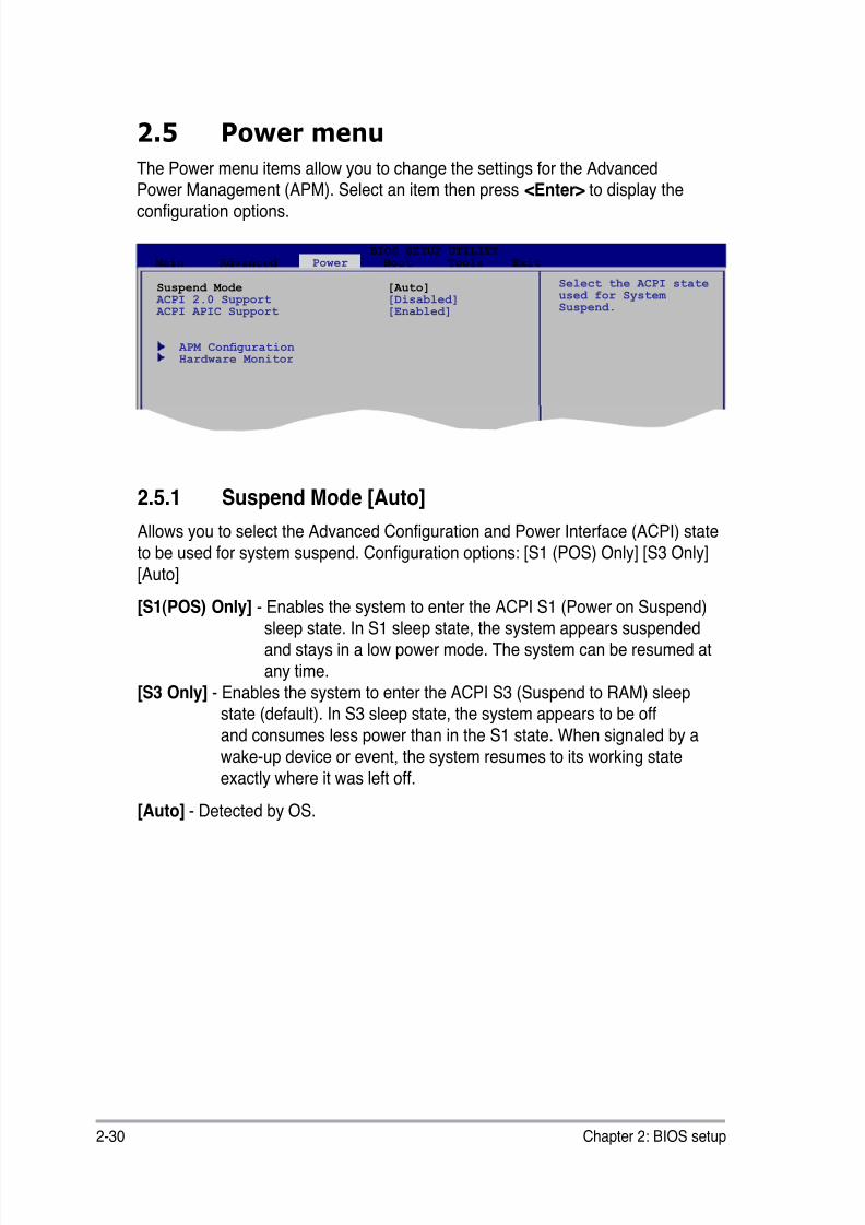
8/12/2019 Asus P5QL-EM Manual
http://slidepdf.com/reader/full/asus-p5ql-em-manual 80/112
2-30 Chapter 2: BIOS setup
2.5 Power menu
The Power menu items allow you to change the settings for the Advanced
Power Management (APM). Select an item then press <Enter> to display theconguration options.
2.5.1 Suspend Mode [Auto]
Allows you to select the Advanced Conguration and Power Interface (ACPI) state
to be used for system suspend. Conguration options: [S1 (POS) Only] [S3 Only]
[Auto]
[S1(POS) Only] - Enables the system to enter the ACPI S1 (Power on Suspend)sleep state. In S1 sleep state, the system appears suspended
and stays in a low power mode. The system can be resumed at
any time.
[S3 Only] - Enables the system to enter the ACPI S3 (Suspend to RAM) sleepstate (default). In S3 sleep state, the system appears to be off
and consumes less power than in the S1 state. When signaled by a
wake-up device or event, the system resumes to its working state
exactly where it was left off.[Auto] - Detected by OS.
Suspend Mode [Auto] ACPI 2.0 Support [Disabled] ACPI APIC Support [Enabled]
APM Conguration Hardware Monitor
Select the ACPI stateused for SystemSuspend.
BIOS SETUP UTILITY Main Advanced Power Boot Tools Exit

8/12/2019 Asus P5QL-EM Manual
http://slidepdf.com/reader/full/asus-p5ql-em-manual 81/112
ASUS P5QL-EM 2-31
2.5.2 ACPI 2.0 Support [Disabled]
Allows you to add more tables for Advanced Conguration and Power Interface
(ACPI) 2.0 specications. Conguration options: [Disabled] [Enabled]
2.5.3 ACPI APIC Support [Enabled]
Allows you to enable or disable the Advanced Conguration and Power Interface
(ACPI) support in the Application-Specic Integrated Circuit (ASIC). When set
to Enabled, the ACPI APIC table pointer is included in the RSDT pointer list.Conguration options: [Disabled] [Enabled]
2.5.4 APM Conguration
APM Conguration
Restore on AC Power Loss [Power Off]
Resume On By PS/2 KB/MOUSE [Disabled]Resume On Ring [Disabled]Resume On PCI Devices [Disabled]Resume On PCIE Devices [Disabled]Resume On RTC Alarm [Disabled]
<Enter> to select whether or not torestart the systemafter AC powerloss.
Restore on AC Power Loss [Power Off]
When set to [Power Off], the system goes into off state after an AC power loss.
When set to [Power On], the system goes on after an AC power loss. When set to
[Last State], the system goes into either off or on state, whatever the system state
was before the AC power loss. Conguration options: [Power Off] [Power On]
[Last State]
Power On By PS/2 KB/Mouse [Disabled]
When set to [Enabled], this parameter allows you to use the PS/2 KB/mouse to
turn on the system. This feature requires an ATX power supply that provides at
least 1A on the +5VSB lead. Conguration options: [Disabled] [Enabled]
Resume On Ring [Disabled]
Allows you to enable or disable RI to generate a wake event.
Conguration options: [Disabled] [Enabled]
Resume On PCI Devices [Disabled]
When set to [Enabled], this parameter allows you to wake the system through a
PCI LAN or modem card. This feature requires an ATX power supply that providesat least 1A on the +5VSB lead. Conguration options: [Disabled] [Enabled]
8/12/2019 Asus P5QL-EM Manual
http://slidepdf.com/reader/full/asus-p5ql-em-manual 82/112
2-32 Chapter 2: BIOS setup
Resume On PCIE Devices [Disabled]
When set to [Enabled], this parameter allows you to wake the system through a
PCI Express card. This feature requires an ATX power supply that provides at least
1A on the +5VSB lead. Conguration options: [Disabled] [Enabled]
Resume On RTC Alarm [Disabled]
Allows you to enable or disable RTC to generate a wake event. When this item is
set to Enabled, the items RTC Alarm Date, RTC Alarm Hour, RTC Alarm Minute,and RTC Alarm Second appear with set values. Conguration options: [Disabled]
[Enabled]
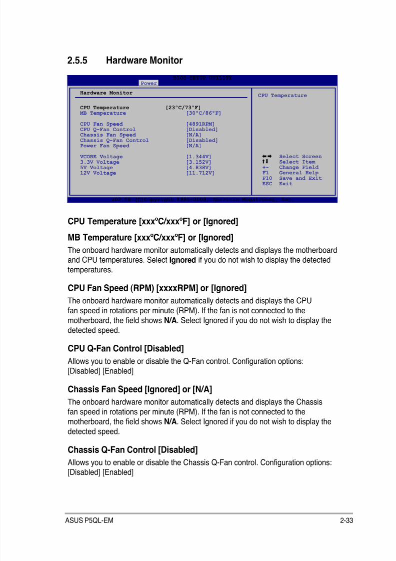
8/12/2019 Asus P5QL-EM Manual
http://slidepdf.com/reader/full/asus-p5ql-em-manual 83/112
ASUS P5QL-EM 2-33
2.5.5 Hardware Monitor
CPU Temperature [xxxºC/xxxºF] or [Ignored]
MB Temperature [xxxºC/xxxºF] or [Ignored]
The onboard hardware monitor automatically detects and displays the motherboardand CPU temperatures. Select Ignored if you do not wish to display the detected
temperatures.
CPU Fan Speed (RPM) [xxxxRPM] or [Ignored]
The onboard hardware monitor automatically detects and displays the CPU
fan speed in rotations per minute (RPM). If the fan is not connected to the
motherboard, the eld shows N/A. Select Ignored if you do not wish to display the
detected speed.
CPU Q-Fan Control [Disabled]
Allows you to enable or disable the Q-Fan control. Conguration options:[Disabled] [Enabled]
Chassis Fan Speed [Ignored] or [N/A]
The onboard hardware monitor automatically detects and displays the Chassis
fan speed in rotations per minute (RPM). If the fan is not connected to the
motherboard, the eld shows N/A. Select Ignored if you do not wish to display the
detected speed.
Chassis Q-Fan Control [Disabled]Allows you to enable or disable the Chassis Q-Fan control. Conguration options:[Disabled] [Enabled]
v02.58 (C)Copyright 1985-2006, American Megatrends, Inc.
Select Screen Select Item
+- Change Field F1 General Help
F10 Save and ExitESC Exit
CPU Temperature
v02.58 (C)Copyright 1985-2008, American Megatrends, Inc.
BIOS SETUP UTILITY Power
Hardware Monitor
CPU Temperature [23ºC/73ºF] MB Temperature [30ºC/86ºF]
CPU Fan Speed [4891RPM]CPU Q-Fan Control [Disabled]Chassis Fan Speed [N/A]Chassis Q-Fan Control [Disabled]Power Fan Speed [N/A]
VCORE Voltage [1.344V]3.3V Voltage [3.152V]5V Voltage [4.838V]12V Voltage [11.712V]
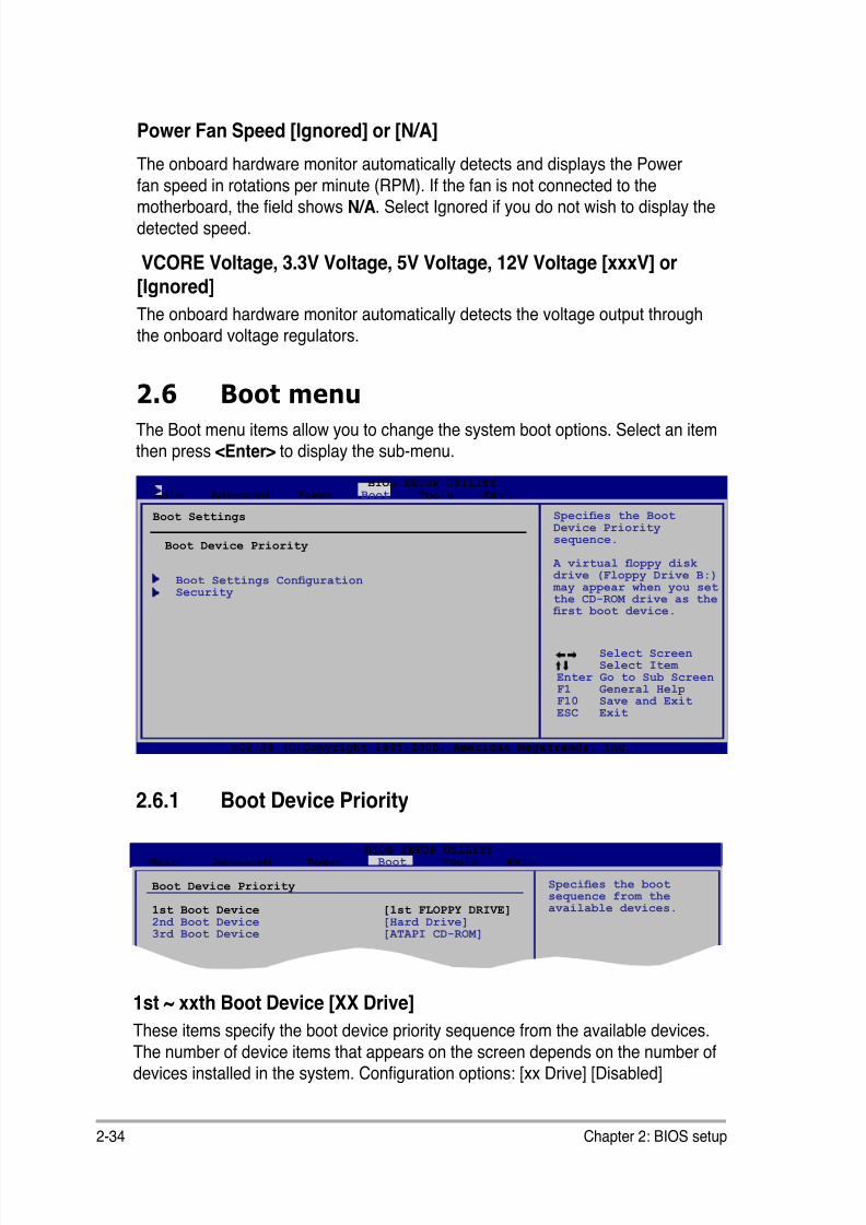
8/12/2019 Asus P5QL-EM Manual
http://slidepdf.com/reader/full/asus-p5ql-em-manual 84/112
2-34 Chapter 2: BIOS setup
2.6 Boot menuThe Boot menu items allow you to change the system boot options. Select an itemthen press <Enter> to display the sub-menu.
2.6.1 Boot Device Priority
1st ~ xxth Boot Device [XX Drive]
These items specify the boot device priority sequence from the available devices.
The number of device items that appears on the screen depends on the number ofdevices installed in the system. Conguration options: [xx Drive] [Disabled]
Boot Device Priority
1st Boot Device [1st FLOPPY DRIVE]2nd Boot Device [Hard Drive]3rd Boot Device [ATAPI CD-ROM]
Species the boot sequence from theavailable devices.
BIOS SETUP UTILITY Main Advanced Power Boot Tools Exit
Select Screen Select Item
Enter Go to Sub ScreenF1 General HelpF10 Save and ExitESC Exit
v02.58 (C)Copyright 1985-2008, American Megatrends, Inc.
Boot Settings Conguration Security
Species the BootDevice Prioritysequence.
A virtual oppy diskdrive (Floppy Drive B:)
may appear when you setthe CD-ROM drive as the rst boot device.
BIOS SETUP UTILITY Main Advanced Power Boot Tools Exit
Boot Device Priority
Boot Settings
Power Fan Speed [Ignored] or [N/A]
The onboard hardware monitor automatically detects and displays the Power
fan speed in rotations per minute (RPM). If the fan is not connected to themotherboard, the eld shows N/A. Select Ignored if you do not wish to display the
detected speed.
VCORE Voltage, 3.3V Voltage, 5V Voltage, 12V Voltage [xxxV] or[Ignored]
The onboard hardware monitor automatically detects the voltage output throughthe onboard voltage regulators.
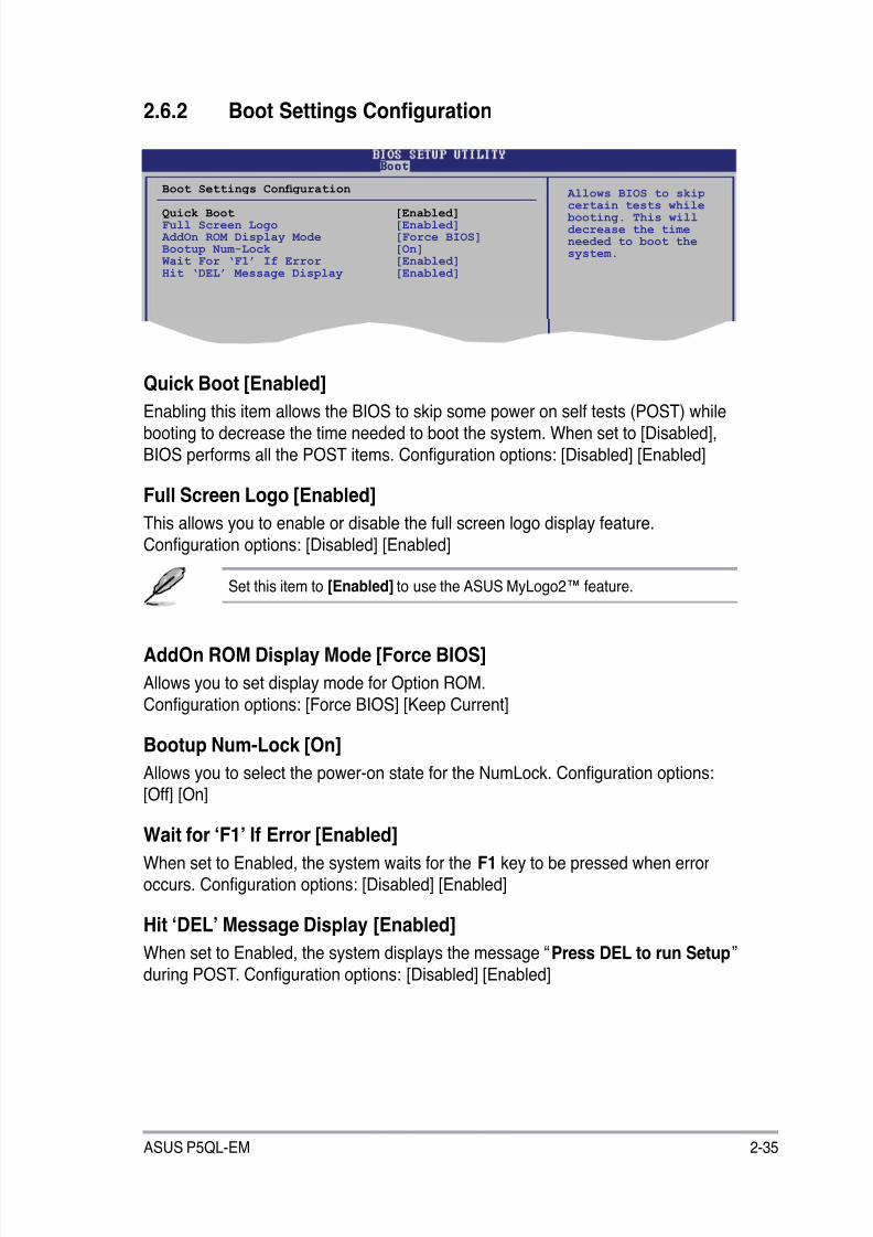
8/12/2019 Asus P5QL-EM Manual
http://slidepdf.com/reader/full/asus-p5ql-em-manual 85/112
ASUS P5QL-EM 2-35
2.6.2 Boot Settings Conguration
Boot Settings Conguration
Quick Boot [Enabled]Full Screen Logo [Enabled] AddOn ROM Display Mode [Force BIOS]Bootup Num-Lock [On] Wait For ‘F1’ If Error [Enabled]Hit ‘DEL’ Message Display [Enabled]
Allows BIOS to skipcertain tests while booting. This willdecrease the timeneeded to boot thesystem.
Set this item to [Enabled] to use the ASUS MyLogo2™ feature.
Quick Boot [Enabled]
Enabling this item allows the BIOS to skip some power on self tests (POST) while
booting to decrease the time needed to boot the system. When set to [Disabled],
BIOS performs all the POST items. Conguration options: [Disabled] [Enabled]
Full Screen Logo [Enabled]
This allows you to enable or disable the full screen logo display feature.
Conguration options: [Disabled] [Enabled]
AddOn ROM Display Mode [Force BIOS]
Allows you to set display mode for Option ROM.
Conguration options: [Force BIOS] [Keep Current]
Bootup Num-Lock [On]
Allows you to select the power-on state for the NumLock. Conguration options:
[Off] [On]
Wait for ‘F1’ If Error [Enabled]
When set to Enabled, the system waits for the F1 key to be pressed when erroroccurs. Conguration options: [Disabled] [Enabled]
Hit ‘DEL’ Message Display [Enabled]
When set to Enabled, the system displays the message “Press DEL to run Setup”
during POST. Conguration options: [Disabled] [Enabled]

8/12/2019 Asus P5QL-EM Manual
http://slidepdf.com/reader/full/asus-p5ql-em-manual 86/112
2-36 Chapter 2: BIOS setup
If you forget your BIOS password, you can clear it by erasing the CMOS RealTime Clock (RTC) RAM. See section “1.9 Jumpers” for information on how to
erase the RTC RAM.
2.6.3 Security
The Security menu items allow you to change the system security settings. Select
an item then press <Enter> to display the conguration options.
Security Settings
Supervisor Password : Not Installed User Password : Not Installed
Change Supervisor Password Change User Passward
<Enter> to change password. <Enter> again todisabled password.
Change Supervisor Password
Select this item to set or change the supervisor password. The SupervisorPassword item on top of the screen shows the default Not Installed. After you set
a password, this item shows Installed.
To set a Supervisor Password:
1. Select the Change Supervisor Password item and press <Enter>.
2. From the password box, type a password composed of at least six letters
and/or numbers, then press <Enter>.3. Conrm the password when prompted.
The message “Password Installed” appears after you successfully set your
password.
To change the supervisor password, follow the same steps as in setting a
supervisor password.
To clear the supervisor password, select the Change Supervisor Password then
press <Enter>. The message “Password uninstalled” appears.
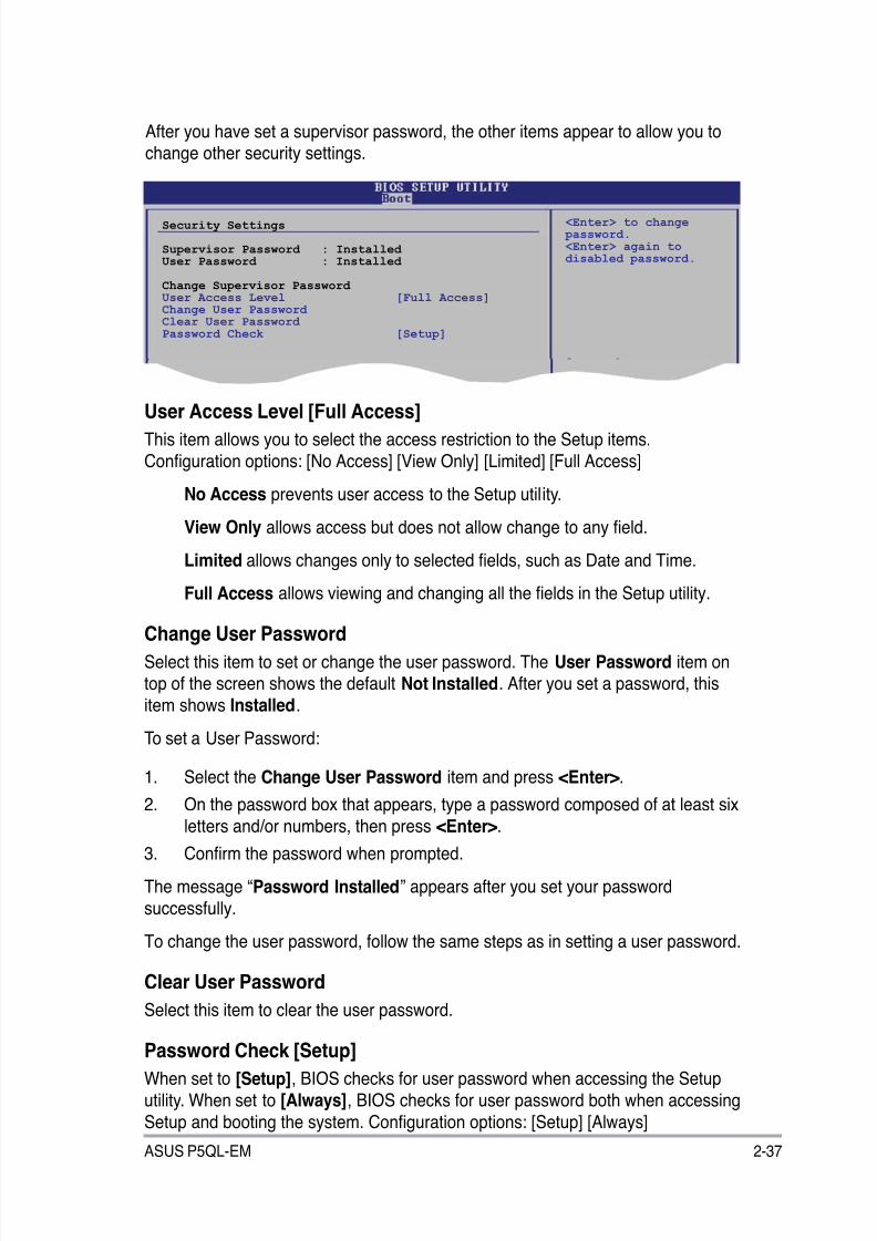
8/12/2019 Asus P5QL-EM Manual
http://slidepdf.com/reader/full/asus-p5ql-em-manual 87/112
ASUS P5QL-EM 2-37
After you have set a supervisor password, the other items appear to allow you tochange other security settings.
User Access Level [Full Access]
This item allows you to select the access restriction to the Setup items.
Conguration options: [No Access] [View Only] [Limited] [Full Access]
No Access prevents user access to the Setup utility.
View Only allows access but does not allow change to any eld.
Limited allows changes only to selected elds, such as Date and Time.
Full Access allows viewing and changing all the elds in the Setup utility.
Change User Password
Select this item to set or change the user password. The User Password item ontop of the screen shows the default Not Installed. After you set a password, this
item shows Installed.
To set a User Password:
1. Select the Change User Password item and press <Enter>.
2. On the password box that appears, type a password composed of at least six
letters and/or numbers, then press <Enter>.
3. Conrm the password when prompted.
The message “Password Installed” appears after you set your password
successfully.
To change the user password, follow the same steps as in setting a user password.
Clear User Password
Select this item to clear the user password.
Password Check [Setup]
When set to [Setup], BIOS checks for user password when accessing the Setup
utility. When set to [Always], BIOS checks for user password both when accessing
Setup and booting the system. Conguration options: [Setup] [Always]
Security Settings
Supervisor Password : Installed User Password : Installed
Change Supervisor Password User Access Level [Full Access]Change User Password Clear User Password Password Check [Setup]
<Enter> to change password. <Enter> again todisabled password.
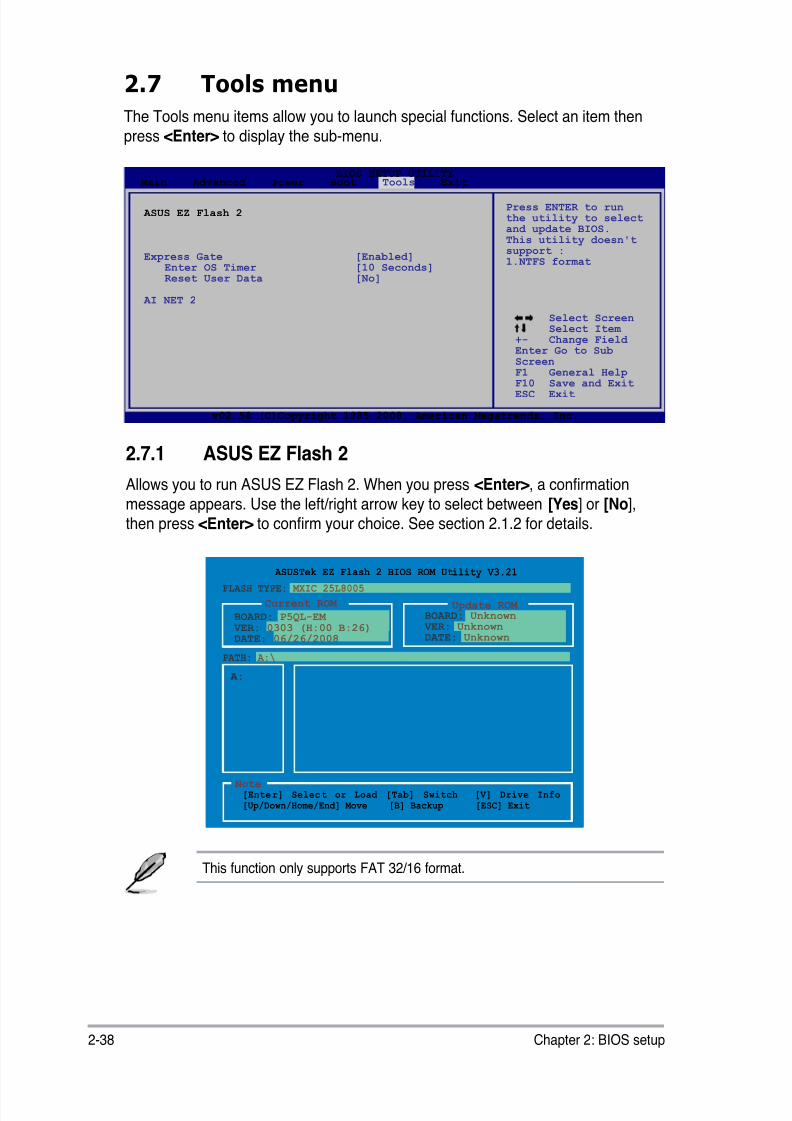
8/12/2019 Asus P5QL-EM Manual
http://slidepdf.com/reader/full/asus-p5ql-em-manual 88/112
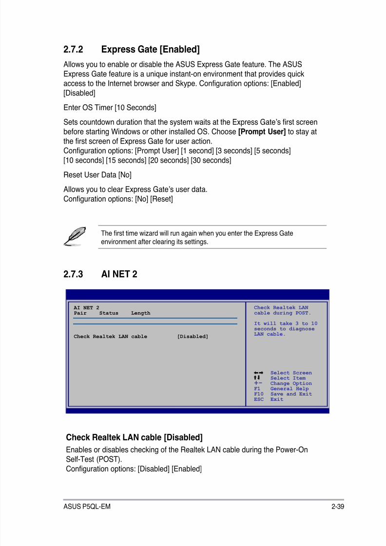
8/12/2019 Asus P5QL-EM Manual
http://slidepdf.com/reader/full/asus-p5ql-em-manual 89/112
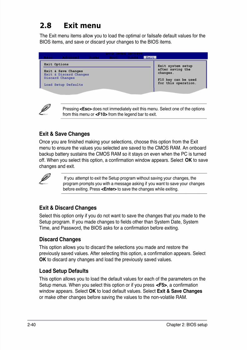
8/12/2019 Asus P5QL-EM Manual
http://slidepdf.com/reader/full/asus-p5ql-em-manual 90/112
2-40 Chapter 2: BIOS setup
Exit & Discard Changes
Select this option only if you do not want to save the changes that you made to the
Setup program. If you made changes to elds other than System Date, SystemTime, and Password, the BIOS asks for a conrmation before exiting.
Discard Changes
This option allows you to discard the selections you made and restore the
previously saved values. After selecting this option, a conrmation appears. Select
OK to discard any changes and load the previously saved values.
Load Setup Defaults
This option allows you to load the default values for each of the parameters on theSetup menus. When you select this option or if you press <F5>, a conrmationwindow appears. Select OK to load default values. Select Exit & Save Changes
or make other changes before saving the values to the non-volatile RAM.
Exit & Save Changes
Once you are nished making your selections, choose this option from the Exit
menu to ensure the values you selected are saved to the CMOS RAM. An onboardbackup battery sustains the CMOS RAM so it stays on even when the PC is turned
off. When you select this option, a conrmation window appears. Select OK to save
changes and exit.
2.8 Exit menu
The Exit menu items allow you to load the optimal or failsafe default values for the
BIOS items, and save or discard your changes to the BIOS items.
Pressing <Esc> does not immediately exit this menu. Select one of the optionsfrom this menu or <F10> from the legend bar to exit.
If you attempt to exit the Setup program without saving your changes, the
program prompts you with a message asking if you want to save your changesbefore exiting. Press <Enter> to save the changes while exiting.
Exit system setupafter saving thechanges.
F10 key can be used for this operation.
Exit Options
Exit & Save ChangesExit & Discard ChangesDiscard Changes
Load Setup Defaults
BIOS SETUP UTILITY Main Advanced Power Boot Tools Exit

8/12/2019 Asus P5QL-EM Manual
http://slidepdf.com/reader/full/asus-p5ql-em-manual 91/112
3Softwaresupport
This chapter describes the contents ofthe support DVD that comes with the
motherboard package.
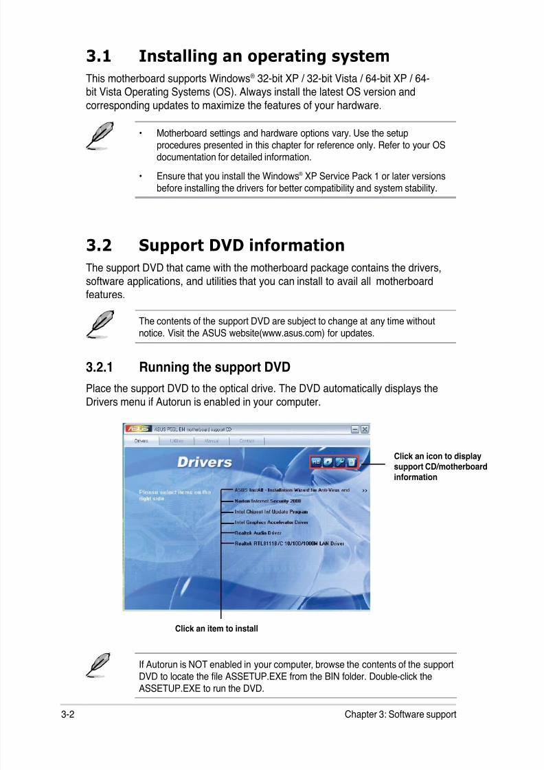
8/12/2019 Asus P5QL-EM Manual
http://slidepdf.com/reader/full/asus-p5ql-em-manual 92/112
3-2 Chapter 3: Software support
If Autorun is NOT enabled in your computer, browse the contents of the supportDVD to locate the le ASSETUP.EXE from the BIN folder. Double-click theASSETUP.EXE to run the DVD.
Click an item to install
3.1 Installing an operating system
This motherboard supports Windows® 32-bit XP / 32-bit Vista / 64-bit XP / 64-bit Vista Operating Systems (OS). Always install the latest OS version and
corresponding updates to maximize the features of your hardware.
3.2 Support DVD informationThe support DVD that came with the motherboard package contains the drivers,
software applications, and utilities that you can install to avail all motherboardfeatures.
3.2.1 Running the support DVDPlace the support DVD to the optical drive. The DVD automatically displays the
Drivers menu if Autorun is enabled in your computer.
• Motherboard settings and hardware options vary. Use the setupprocedures presented in this chapter for reference only. Refer to your OSdocumentation for detailed information.
• Ensure that you install the Windows® XP Service Pack 1 or later versionsbefore installing the drivers for better compatibility and system stability.
The contents of the support DVD are subject to change at any time withoutnotice. Visit the ASUS website(www.asus.com) for updates.
Click an icon to displaysupport CD/motherboardinformation
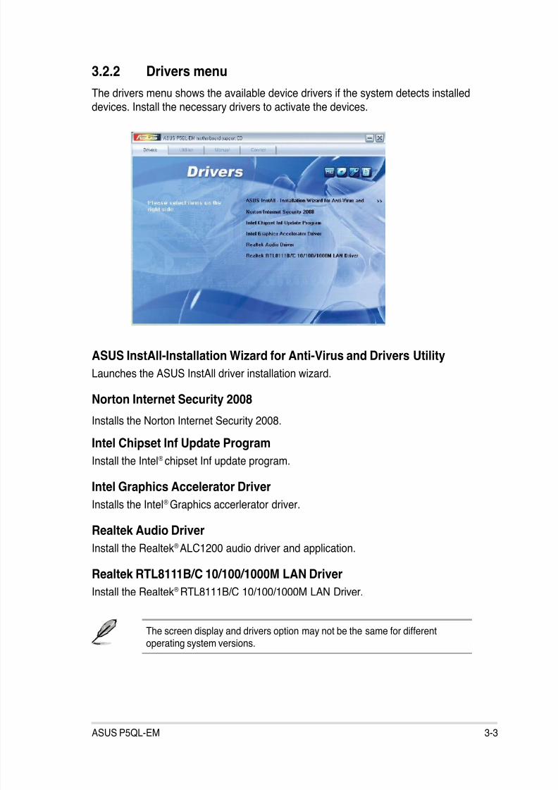
8/12/2019 Asus P5QL-EM Manual
http://slidepdf.com/reader/full/asus-p5ql-em-manual 93/112
3-3ASUS P5QL-EM
3.2.2 Drivers menu
The drivers menu shows the available device drivers if the system detects installed
devices. Install the necessary drivers to activate the devices.
ASUS InstAll-Installation Wizard for Anti-Virus and Drivers Utility
Launches the ASUS InstAll driver installation wizard.
Norton Internet Security 2008
Installs the Norton Internet Security 2008.
Intel Chipset Inf Update Program
Install the Intel® chipset Inf update program.
Intel Graphics Accelerator Driver
Installs the Intel®
Graphics accerlerator driver.
Realtek Audio Driver
Install the Realtek® ALC1200 audio driver and application.
Realtek RTL8111B/C 10/100/1000M LAN Driver
Install the Realtek® RTL8111B/C 10/100/1000M LAN Driver.
The screen display and drivers option may not be the same for differentoperating system versions.
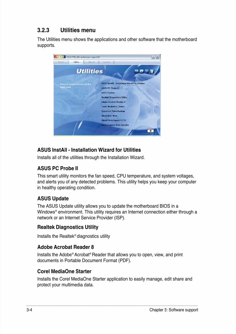
8/12/2019 Asus P5QL-EM Manual
http://slidepdf.com/reader/full/asus-p5ql-em-manual 94/112
3-4 Chapter 3: Software support
3.2.3 Utilities menu
The Utilities menu shows the applications and other software that the motherboard
supports.
ASUS InstAll - Installation Wizard for Utilities
Installs all of the utilities through the Installation Wizard.
ASUS PC Probe II
This smart utility monitors the fan speed, CPU temperature, and system voltages,
and alerts you of any detected problems. This utility helps you keep your computer
in healthy operating condition.
ASUS Update
The ASUS Update utility allows you to update the motherboard BIOS in a
Windows
®
environment. This utility requires an Internet connection either through anetwork or an Internet Service Provider (ISP).
Realtek Diagnostics Utility
Installs the Realtek® diagnostics utility
Adobe Acrobat Reader 8
Installs the Adobe® Acrobat® Reader that allows you to open, view, and print
documents in Portable Document Format (PDF).
Corel MediaOne Starter
Installs the Corel MediaOne Starter application to easily manage, edit share andprotect your multimedia data.
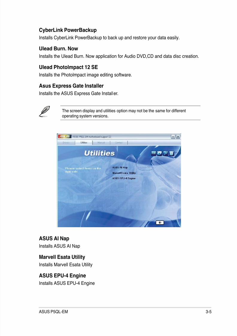
8/12/2019 Asus P5QL-EM Manual
http://slidepdf.com/reader/full/asus-p5ql-em-manual 95/112
3-5ASUS P5QL-EM
The screen display and utilities option may not be the same for differentoperating system versions.
CyberLink PowerBackup
Installs CyberLink PowerBackup to back up and restore your data easily.
Ulead Burn. Now
Installs the Ulead Burn. Now application for Audio DVD,CD and data disc creation.
Ulead Photolmpact 12 SE
Installs the Photolmpact image editing software.
Asus Express Gate Installer
Installs the ASUS Express Gate Installer.
ASUS AI Nap
Installs ASUS AI Nap
Marvell Esata Utility
Installs Marvell Esata Utility
ASUS EPU-4 Engine
Installs ASUS EPU-4 Engine
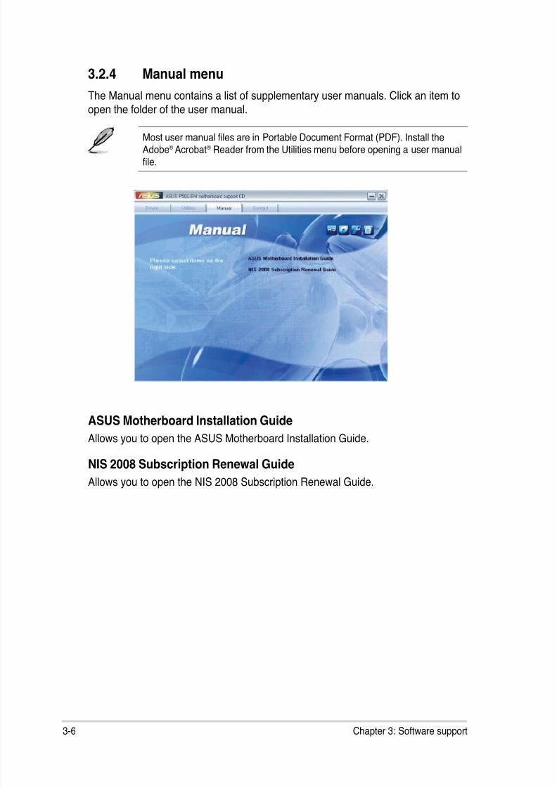
8/12/2019 Asus P5QL-EM Manual
http://slidepdf.com/reader/full/asus-p5ql-em-manual 96/112
3-6 Chapter 3: Software support
3.2.4 Manual menu
The Manual menu contains a list of supplementary user manuals. Click an item to
open the folder of the user manual.
Most user manual les are in Portable Document Format (PDF). Install theAdobe® Acrobat® Reader from the Utilities menu before opening a user manual
le.
ASUS Motherboard Installation Guide
Allows you to open the ASUS Motherboard Installation Guide.
NIS 2008 Subscription Renewal Guide
Allows you to open the NIS 2008 Subscription Renewal Guide.

8/12/2019 Asus P5QL-EM Manual
http://slidepdf.com/reader/full/asus-p5ql-em-manual 97/112
3-7ASUS P5QL-EM
3.2.5 ASUS Contact information
Click the Contact tab to display the ASUS contact information. You can also nd
this information on the inside front cover of this user guide.
3.2.6 Other information
The icons on the top right corner of the screen give additional information on themotherboard and the contents of the support DVD. Click an icon to display the
specied information.
Motherboard Info
Displays the general specications of the motherboard.
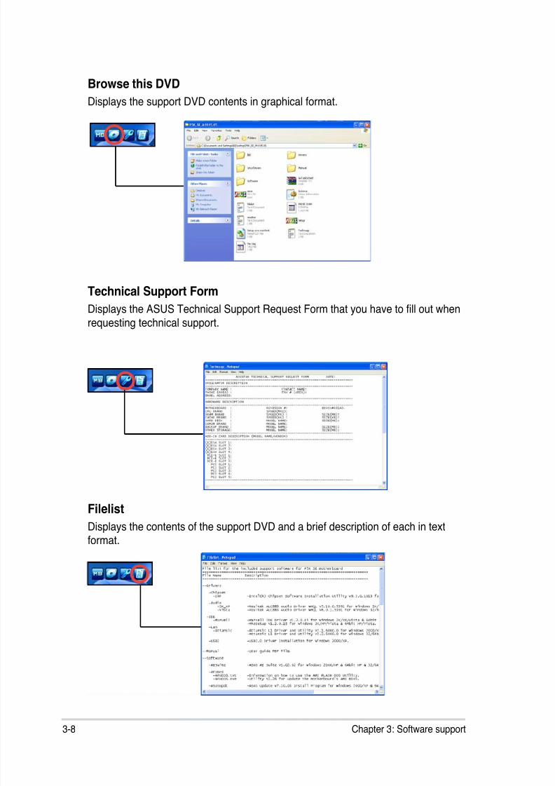
8/12/2019 Asus P5QL-EM Manual
http://slidepdf.com/reader/full/asus-p5ql-em-manual 98/112
3-8 Chapter 3: Software support
Technical Support Form
Displays the ASUS Technical Support Request Form that you have to ll out when
requesting technical support.
Filelist
Displays the contents of the support DVD and a brief description of each in textformat.
Browse this DVD
Displays the support DVD contents in graphical format.
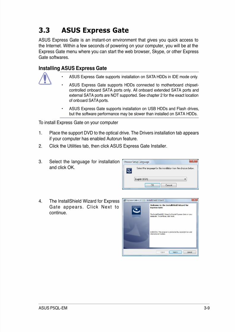
8/12/2019 Asus P5QL-EM Manual
http://slidepdf.com/reader/full/asus-p5ql-em-manual 99/112
3-9ASUS P5QL-EM
3.3 ASUS Express Gate
ASUS Express Gate is an instant-on environment that gives you quick access tothe Internet. Within a few seconds of powering on your computer, you will be at the
Express Gate menu where you can start the web browser, Skype, or other ExpressGate softwares.
Installing ASUS Express Gate
• ASUS Express Gate supports installation on SATA HDDs in IDE mode only.
• ASUS Express Gate supports HDDs connected to motherboard chipset-controlled onboard SATA ports only. All onboard extended SATA ports andexternal SATA ports are NOT supported. See chapter 2 for the exact locationof onboard SATA ports.
• ASUS Express Gate supports installation on USB HDDs and Flash drives,but the software performance may be slower than installed on SATA HDDs.
To install Express Gate on your computer
1. Place the support DVD to the optical drive. The Drivers installation tab appears
if your computer has enabled Autorun feature.
2. Click the Utilities tab, then click ASUS Express Gate Installer.
3. Select the language for installationand click OK.
4. The InstallShield Wizard for Express
Gate appears. Cl ick Next to
continue.
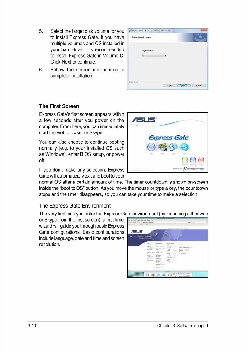
8/12/2019 Asus P5QL-EM Manual
http://slidepdf.com/reader/full/asus-p5ql-em-manual 100/112
8/12/2019 Asus P5QL-EM Manual
http://slidepdf.com/reader/full/asus-p5ql-em-manual 101/112
3-11ASUS P5QL-EM
Knowing the Express Gate hot-keysHere is a list of common-used hot-keys for Express Gate.
In the First Screen:
Key Function
PAUSE/BREAK Power-off
ESC Continue to boot OS
DEL Enter BIOS setupF8 Enter Boot selection pop-up
In the Express Gate Environment:
Key Function
<Alt> + <Tab> Switch between softwares
<Ctrl> + <Alt> + <Del> Bring up Power-Off dialog box
<Ctrl> + <Alt> + <Print Screen> Save screen snapshot as picture to le
Once inside the Express Gate environment, click on the icons on the LaunchBar,
by default at bottom of the screen, to launch or switch between softwares. You can
re-arrange, re-size and move windows. Bring a window to the foreground by clicking
within it or by clicking on its corresponding software icon. Re-size a window by dragging
any of its four corners. Move a window by dragging its title bar.
Besides using the LaunchBar, you can also switch between softwares by pressing
<Alt> +<Tab> on the keyboard. You can also right-click anywhere on the desktop to
bring up a menu of softwares.
The red triangle on an software icon in the LaunchBar denotes that the software is
already running. This means that you can switch to it without any delay. In the rarecase where an software stops responding, right-click on its icon to force close it.

8/12/2019 Asus P5QL-EM Manual
http://slidepdf.com/reader/full/asus-p5ql-em-manual 102/112
3-12 Chapter 3: Software support
Using the Conguration Panel
Use the conguration panel to change various Express Gate settings.
Click on an icon to open a particular conguration tool. The following tools are
available:
• Date and Time: set current date and time as well as time zone.
• Input Method: choose your preferred input language and method.
• Language and Keyboard: choose your language and keyboard preferences.
• LaunchBar Settings: customize your LaunchBar (where it docks, whether it
auto-hides, etc.)
• Network: Specify how your computer connects to the Internet. Enable all the
network ports that you may use (LAN1, LAN2, and/or wireless [optional]). LAN1and LAN2 refer to the two RJ-45 network ports on your computer.
• The number of the LAN ports may differ from motherboards.
• You can connect the LAN cable to either port, and Express Gate willautomatically use the connected port.
Also specify whether each port uses DHCP (most common) or static IP. ForPPPoE and wireless (optional), set the login credentials (user name, password,
SSID, etc.) as well.
• Environment Settings: This function allows you to clear the Express Gate settings,
as well as any personal information stored by the web browser (Bookmarks,
Cookies, History, etc.). The user data will be reset to the original default
conguration.
After you click Restore System, a conrmation dialog box will open. If you click“Yes” in the conrmation dialog box, your system will immediately restart and
then re-enter Express Gate to nish clearing the settings. This is also useful in
the rare case where settings might become corrupted.
The rst-time Wizard will run again when you enter the Express Gate environmentafter clearing its settings.
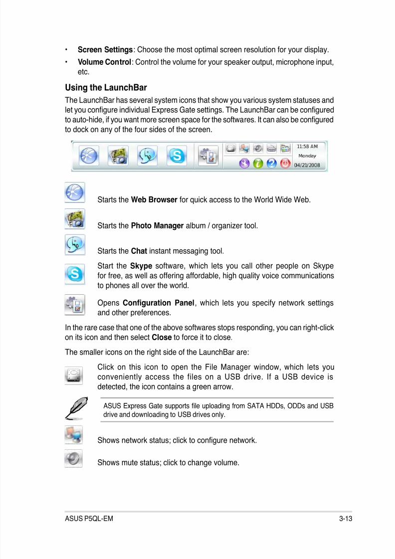
8/12/2019 Asus P5QL-EM Manual
http://slidepdf.com/reader/full/asus-p5ql-em-manual 103/112
3-13ASUS P5QL-EM
• Screen Settings: Choose the most optimal screen resolution for your display.
• Volume Control: Control the volume for your speaker output, microphone input,etc.
Using the LaunchBarThe LaunchBar has several system icons that show you various system statuses andlet you congure individual Express Gate settings. The LaunchBar can be congured
to auto-hide, if you want more screen space for the softwares. It can also be congured
to dock on any of the four sides of the screen.
Starts the Web Browser for quick access to the World Wide Web.
Starts the Photo Manager album / organizer tool.
Starts the Chat instant messaging tool.
Start the Skype software, which lets you call other people on Skypefor free, as well as offering affordable, high quality voice communications
to phones all over the world.
Opens Conguration Panel, which lets you specify network settingsand other preferences.
In the rare case that one of the above softwares stops responding, you can right-clickon its icon and then select Close to force it to close.
The smaller icons on the right side of the LaunchBar are:
Click on this icon to open the File Manager window, which lets you
conveniently access the files on a USB drive. If a USB device is
detected, the icon contains a green arrow.
ASUS Express Gate supports le uploading from SATA HDDs, ODDs and USBdrive and downloading to USB drives only.
Shows network status; click to congure network.
Shows mute status; click to change volume.
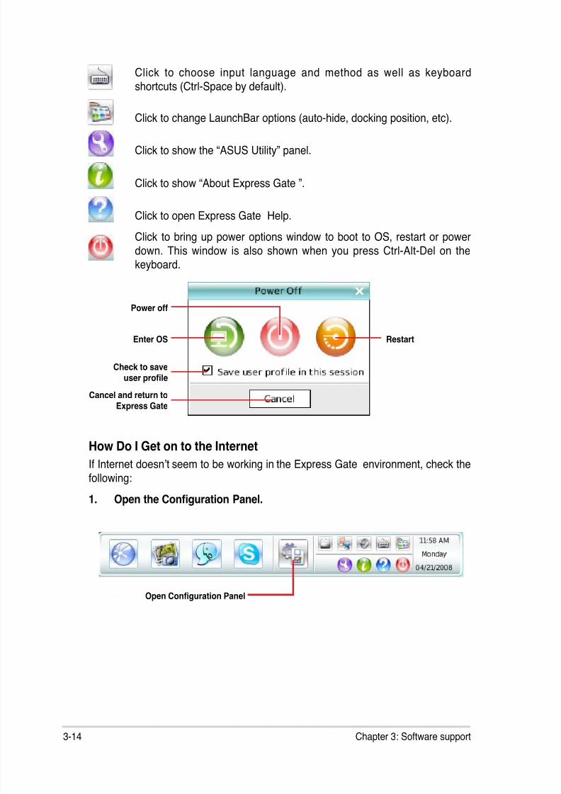
8/12/2019 Asus P5QL-EM Manual
http://slidepdf.com/reader/full/asus-p5ql-em-manual 104/112
3-14 Chapter 3: Software support
Click to choose input language and method as well as keyboard
shortcuts (Ctrl-Space by default).
Click to change LaunchBar options (auto-hide, docking position, etc).
Click to show the “ASUS Utility” panel.
Click to show “About Express Gate ”.
Click to open Express Gate Help.
Click to bring up power options window to boot to OS, restart or power
down. This window is also shown when you press Ctrl-Alt-Del on thekeyboard.
Power off
Enter OS
Cancel and return toExpress Gate
Restart
Check to save
user prole
How Do I Get on to the Internet
If Internet doesn’t seem to be working in the Express Gate environment, check the
following:
1. Open the Conguration Panel.
Open Conguration Panel
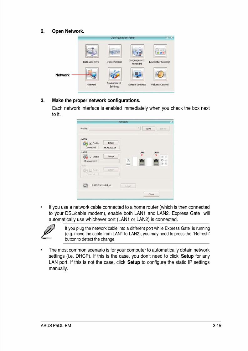
8/12/2019 Asus P5QL-EM Manual
http://slidepdf.com/reader/full/asus-p5ql-em-manual 105/112
3-15ASUS P5QL-EM
2. Open Network.
3. Make the proper network congurations.
Each network interface is enabled immediately when you check the box next
to it.
Network
• If you use a network cable connected to a home router (which is then connected
to your DSL/cable modem), enable both LAN1 and LAN2. Express Gate willautomatically use whichever port (LAN1 or LAN2) is connected.
If you plug the network cable into a different port while Express Gate is running(e.g. move the cable from LAN1 to LAN2), you may need to press the “Refresh”button to detect the change.
• The most common scenario is for your computer to automatically obtain networksettings (i.e. DHCP). If this is the case, you don’t need to click Setup for any
LAN port. If this is not the case, click Setup to congure the static IP settings
manually.

8/12/2019 Asus P5QL-EM Manual
http://slidepdf.com/reader/full/asus-p5ql-em-manual 106/112
3-16 Chapter 3: Software support
• If you have wireless network, click Setup for the WiFi option. In the WiFi tab of
the Advanced Network Settings box, enter the name of your wireless access
point in the SSID eld. If your wireless access point has security enabled, select
the corresponding security algorithm from the drop-down list (e.g. WEPAUTO)
in the Encryption Type eld, and enter the password.Click OK to enable WiFi and establish the wireless connection.
• If you use a network cable connected directly to your DSL/cable modem (no routerin between), click Setup for xDSL/cable dial-up. This method is also referred to as
PPPoE. Choose whether the DSL/cable modem is connected to your computer’s
LAN port. Then enter the username and password for your dial-up account.
Click OK to enable xDSL/cable dial-up and establish the PPPoE connection.
When PPPoE is enabled, the port it uses will automatically be unchecked andgrayed out.
Using the Photo Manager
Express Gate provides a easy-to-use Photo Manager that allows you to view pictures
stored in your hard drive or external storage devices (such as USB dongles, cardreaders, or optical disks). You can view pictures in thumbnail view; in an enlarged view
individually; in a lename/data list view; or play them in a slideshow with background
music and fancy transition effects. JPEG, GIF, BMP, and PNG formats are supported.
Refer to the on-line Help for detailed software operation.
S h o w s t h eimage folder(s)found in yourh a r d d r i v eor externa l
devices
Shows user-created imagealbum(s)
I m a g econtrol bar
V i e w m o d eselection
HelpPhoto slideshow
ASUS Express Gate supports HDDs connected to motherboard chipset-
controlled onboard SATA ports only. All onboard extended SATA ports andexternal SATA ports are NOT supported.
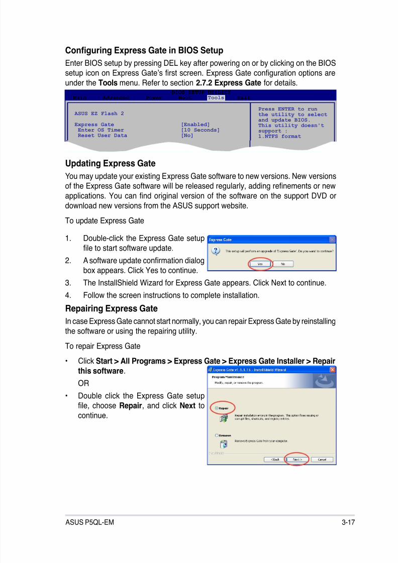
8/12/2019 Asus P5QL-EM Manual
http://slidepdf.com/reader/full/asus-p5ql-em-manual 107/112
3-17ASUS P5QL-EM
Conguring Express Gate in BIOS Setup
Enter BIOS setup by pressing DEL key after powering on or by clicking on the BIOS
setup icon on Express Gate’s rst screen. Express Gate conguration options are
under the Tools menu. Refer to section 2.7.2 Express Gate for details.
Updating Express Gate
You may update your existing Express Gate software to new versions. New versionsof the Express Gate software will be released regularly, adding renements or new
applications. You can nd original version of the software on the support DVD or
download new versions from the ASUS support website.
To update Express Gate
1. Double-click the Express Gate setup
le to start software update.
2. A software update conrmation dialog
box appears. Click Yes to continue.3. The InstallShield Wizard for Express Gate appears. Click Next to continue.
4. Follow the screen instructions to complete installation.
Repairing Express Gate
In case Express Gate cannot start normally, you can repair Express Gate by reinstalling
the software or using the repairing utility.
To repair Express Gate
• Click Start > All Programs > Express Gate > Express Gate Installer > Repairthis software.
OR
• Double click the Express Gate setuple, choose Repair, and click Next tocontinue.
BIOS SETUP UTILITY Main Advanced Power Boot Tools Exit
ASUS EZ Flash 2
Express Gate [Enabled] Enter OS Timer [10 Seconds] Reset User Data [No]
Press ENTER to runthe utility to selectand update BIOS.This utility doesn'tsupport :1.NTFS format

8/12/2019 Asus P5QL-EM Manual
http://slidepdf.com/reader/full/asus-p5ql-em-manual 108/112
3-18 Chapter 3: Software support

8/12/2019 Asus P5QL-EM Manual
http://slidepdf.com/reader/full/asus-p5ql-em-manual 109/112
ACPU features
The Appendix describes the CPU
features that the motherboard supports.

8/12/2019 Asus P5QL-EM Manual
http://slidepdf.com/reader/full/asus-p5ql-em-manual 110/112
A-2 Appendix: CPU features
A.1 Enhanced Intel SpeedStep® Technology (EIST)
A.1.1 System requirements
Before using EIST, check your system if it meets the following requirements:
• Intel® Pentium® 4 processor with EIST support
• BIOS le with EIST support
• Operating system with EIST support (Windows® XP SP2/Linux 2.6 kernel or
later versions)
A.1.2 Using the EIST
To use the EIST feature:
1. Turn on the computer, then enter the BIOS Setup.
2. Go to the Advanced Menu, highlight CPU Conguration,
then press <Enter>.
3. Set the Intel(R) SpeedStep Technology item to [Automatic],
then press <Enter>.
4. Press <F10> to save your changes and exit the BIOS setup.
5. After the computer restarts, right click on a blank space on the desktop, then
select Properties from the pop-up menu.
6. When the Display Properties window
appears, click the Screen Saver tab.
7. Click the Power button on the
Monitor power section to open thePower Options Properties window.
• The motherboard comes with a BIOS le that supports EIST. You candownload the latest BIOS le from the ASUS website (www.asus.com/ support/download/) if you need to update the BIOS. See Chapter 2 fordetails.
• Visit www.intel.com for more information on the EIST feature.
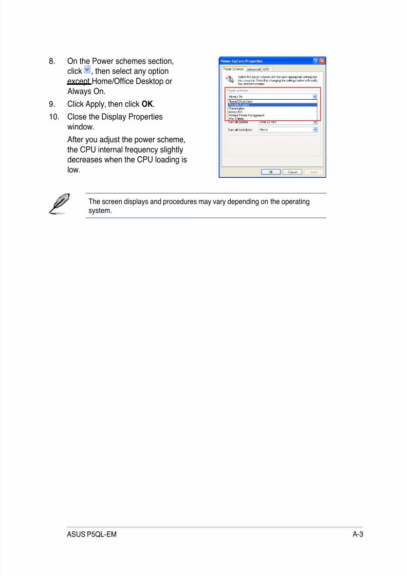
8/12/2019 Asus P5QL-EM Manual
http://slidepdf.com/reader/full/asus-p5ql-em-manual 111/112
ASUS P5QL-EM A-3
8. On the Power schemes section,click , then select any option
except Home/Ofce Desktop or
Always On.9. Click Apply, then click OK.
10. Close the Display Properties
window.
After you adjust the power scheme,
the CPU internal frequency slightlydecreases when the CPU loading is
low.
The screen displays and procedures may vary depending on the operatingsystem.
8/12/2019 Asus P5QL-EM Manual
http://slidepdf.com/reader/full/asus-p5ql-em-manual 112/112
A.2 Intel® Hyper-Threading Technology
Using the Hyper-Threading Technology
To use the Hyper-Threading Technology:
1. Install an Intel® Pentium® 4 CPU that supports Hyper-Threading Technology.
2. Power up the system and enter the BIOS Setup. Under the Advanced Menu,make sure that the item Hyper-Threading Technology is set to Enabled.
The BIOS item appears only if you installed a CPU that supports
Hyper-Threading Technology.
3. Restart the computer.
• The motherboard supports Intel® Pentium® 4 LGA775 processors withHyper-Threading Technology.
• Hyper-Threading Technology is supported under Windows® XP and Linux2.4.x (kernel) and later versions only. Under Linux, use the Hyper-Threading compiler to compile the code. If you are using any otheroperating systems, disable the Hyper-Threading Techonology item in theBIOS to ensure system stability and performance.
• Installing Windows® XP Service Pack 1 or later version is recommended.
• Make sure to enable the Hyper-Threading Technology item in BIOS beforeinstalling a supported operating system.
• For more information on Hyper-Threading Technology, visitwww.intel.com/info/hyperthreading.