Embed Size (px)
Citation preview

Auxilio a Resolução do PjBLProjeto da Rede do Bloco 8
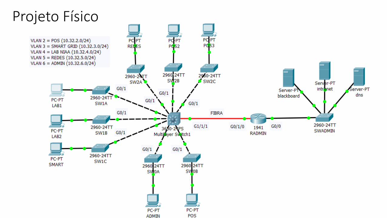
Projeto Físico
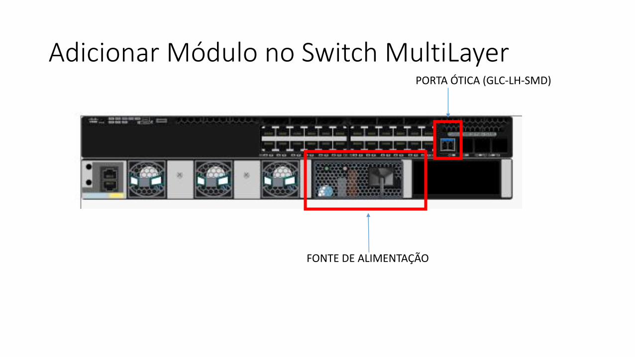
Adicionar Módulo no Switch MultiLayer
FONTE DE ALIMENTAÇÃO
PORTA ÓTICA (GLC-LH-SMD)
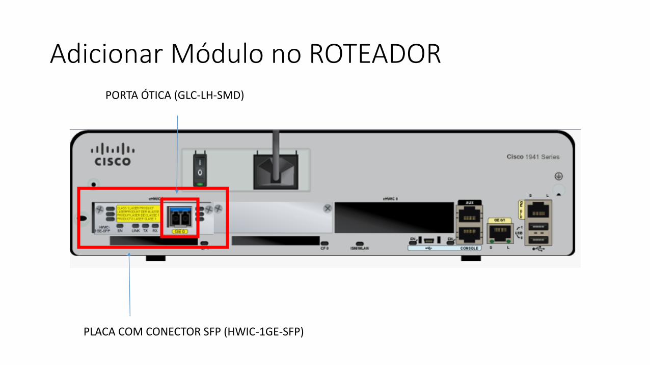
Adicionar Módulo no ROTEADOR
PLACA COM CONECTOR SFP (HWIC-1GE-SFP)
PORTA ÓTICA (GLC-LH-SMD)
Projeto Lógico
1. Configurar Roteamento entre VLANs no Switch MultiLayer
2. Configurar VLANs nos Switches L2
3. Configurar DHCP no Switch MultiLayer
4. Configurar o roteamento entre o Bloco 8 e o prédio Administrativo
5. Configurar IP dos Servidores do Bloco Administrativo
6. Configurar o Servidor DNS
7. Criar Páginas HTML de exemplo dos servidores Blackboard e Intranet
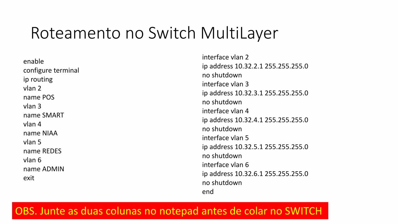
Roteamento no Switch MultiLayer
enableconfigure terminalip routingvlan 2name POSvlan 3name SMARTvlan 4name NIAAvlan 5name REDESvlan 6name ADMINexit
interface vlan 2ip address 10.32.2.1 255.255.255.0no shutdowninterface vlan 3ip address 10.32.3.1 255.255.255.0no shutdowninterface vlan 4ip address 10.32.4.1 255.255.255.0no shutdowninterface vlan 5ip address 10.32.5.1 255.255.255.0no shutdowninterface vlan 6ip address 10.32.6.1 255.255.255.0no shutdownend
OBS. Junte as duas colunas no notepad antes de colar no SWITCH
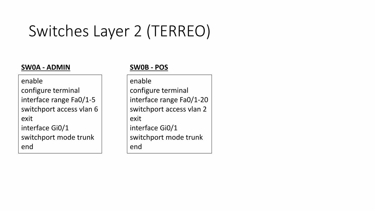
Switches Layer 2 (TERREO)
enableconfigure terminalinterface range Fa0/1-5switchport access vlan 6exitinterface Gi0/1switchport mode trunkend
SW0A - ADMIN
enableconfigure terminalinterface range Fa0/1-20switchport access vlan 2exitinterface Gi0/1switchport mode trunkend
SW0B - POS
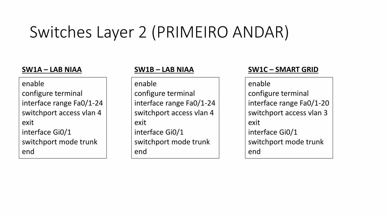
Switches Layer 2 (PRIMEIRO ANDAR)
enableconfigure terminalinterface range Fa0/1-24switchport access vlan 4exitinterface Gi0/1switchport mode trunkend
SW1A – LAB NIAA
enableconfigure terminalinterface range Fa0/1-24switchport access vlan 4exitinterface Gi0/1switchport mode trunkend
SW1B – LAB NIAA
enableconfigure terminalinterface range Fa0/1-20switchport access vlan 3exitinterface Gi0/1switchport mode trunkend
SW1C – SMART GRID
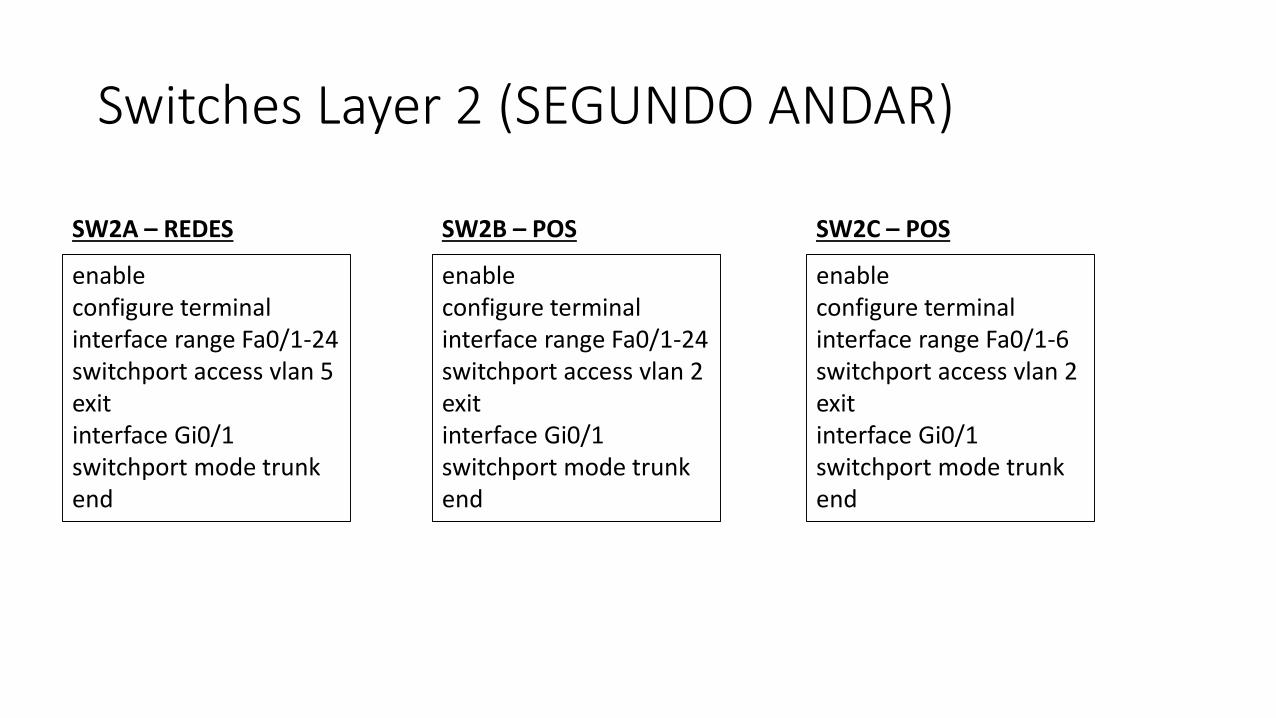
Switches Layer 2 (SEGUNDO ANDAR)
enableconfigure terminalinterface range Fa0/1-24switchport access vlan 5exitinterface Gi0/1switchport mode trunkend
SW2A – REDES
enableconfigure terminalinterface range Fa0/1-24switchport access vlan 2exitinterface Gi0/1switchport mode trunkend
SW2B – POS
enableconfigure terminalinterface range Fa0/1-6switchport access vlan 2exitinterface Gi0/1switchport mode trunkend
SW2C – POS

DHCP no Switch MultiLayerenableconfigure terminalip dhcp pool posnetwork 10.32.2.0 255.255.255.0dns-server 200.192.112.2default-router 10.32.2.1exitip dhcp pool smartnetwork 10.32.3.0 255.255.255.0dns-server 200.192.112.2default-router 10.32.3.1exitip dhcp pool niaanetwork 10.32.4.0 255.255.255.0dns-server 200.192.112.2default-router 10.32.4.1exit
ip dhcp pool redesnetwork 10.32.5.0 255.255.255.0dns-server 200.192.112.2default-router 10.32.5.1exitip dhcp pool adminnetwork 10.32.6.0 255.255.255.0dns-server 200.192.112.2default-router 10.32.6.1exitip dhcp excluded-address 10.32.2.0 10.32.2.10ip dhcp excluded-address 10.32.3.0 10.32.3.10ip dhcp excluded-address 10.32.4.0 10.32.4.10ip dhcp excluded-address 10.32.5.0 10.32.5.10ip dhcp excluded-address 10.32.6.0 10.32.6.10end
OBS. Junte as colunas no notepad antes de colar no SWITCH
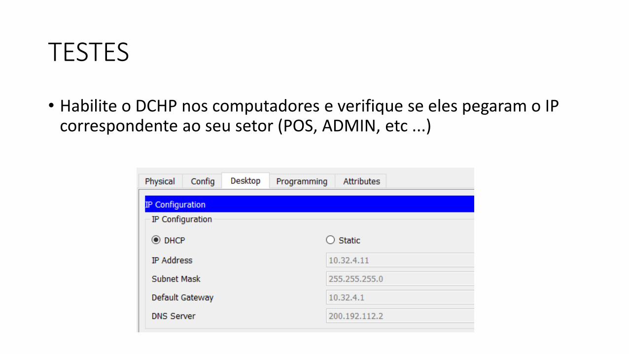
TESTES
• Habilite o DCHP nos computadores e verifique se eles pegaram o IP correspondente ao seu setor (POS, ADMIN, etc ...)
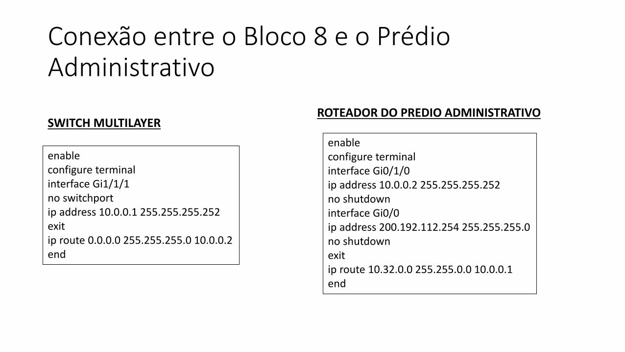
Conexão entre o Bloco 8 e o Prédio Administrativo
enableconfigure terminalinterface Gi1/1/1no switchportip address 10.0.0.1 255.255.255.252exitip route 0.0.0.0 255.255.255.0 10.0.0.2end
enableconfigure terminalinterface Gi0/1/0ip address 10.0.0.2 255.255.255.252no shutdowninterface Gi0/0ip address 200.192.112.254 255.255.255.0no shutdownexitip route 10.32.0.0 255.255.0.0 10.0.0.1end
SWITCH MULTILAYERROTEADOR DO PREDIO ADMINISTRATIVO
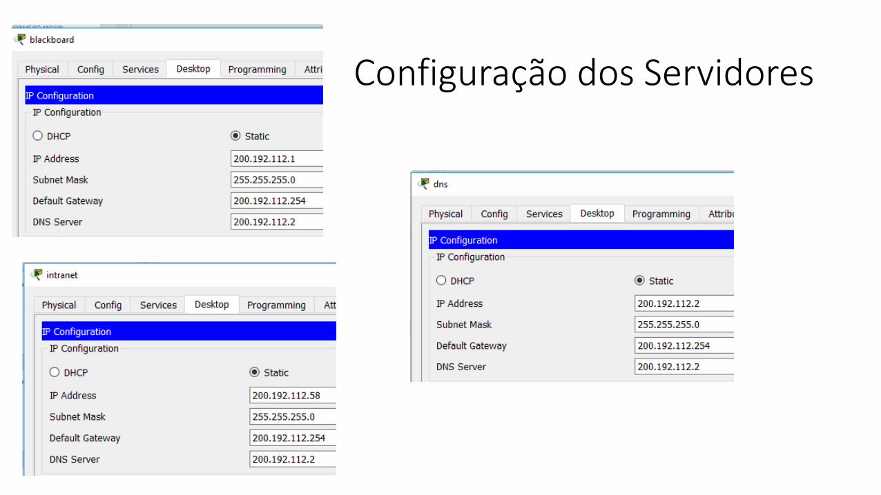
Configuração dos Servidores
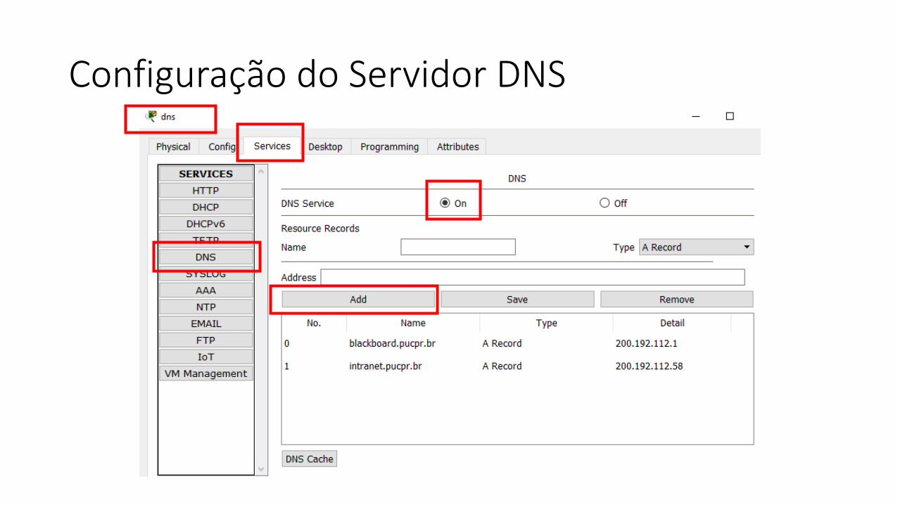
Configuração do Servidor DNS
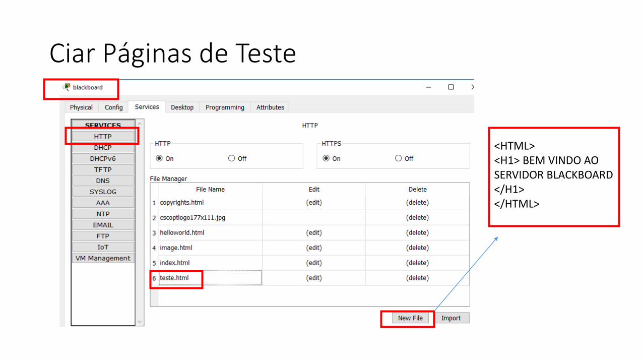
Ciar Páginas de Teste
<HTML><H1> BEM VINDO AO SERVIDOR BLACKBOARD</H1></HTML>
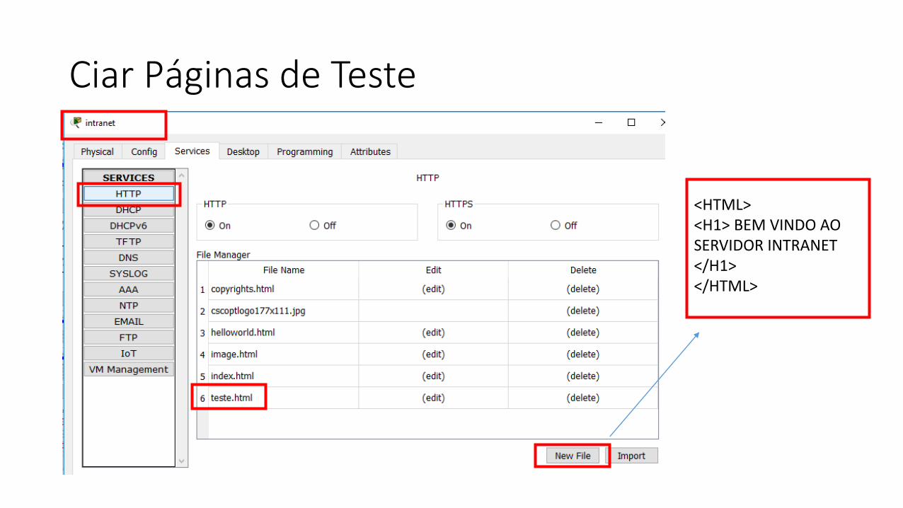
Ciar Páginas de Teste
<HTML><H1> BEM VINDO AO SERVIDOR INTRANET</H1></HTML>
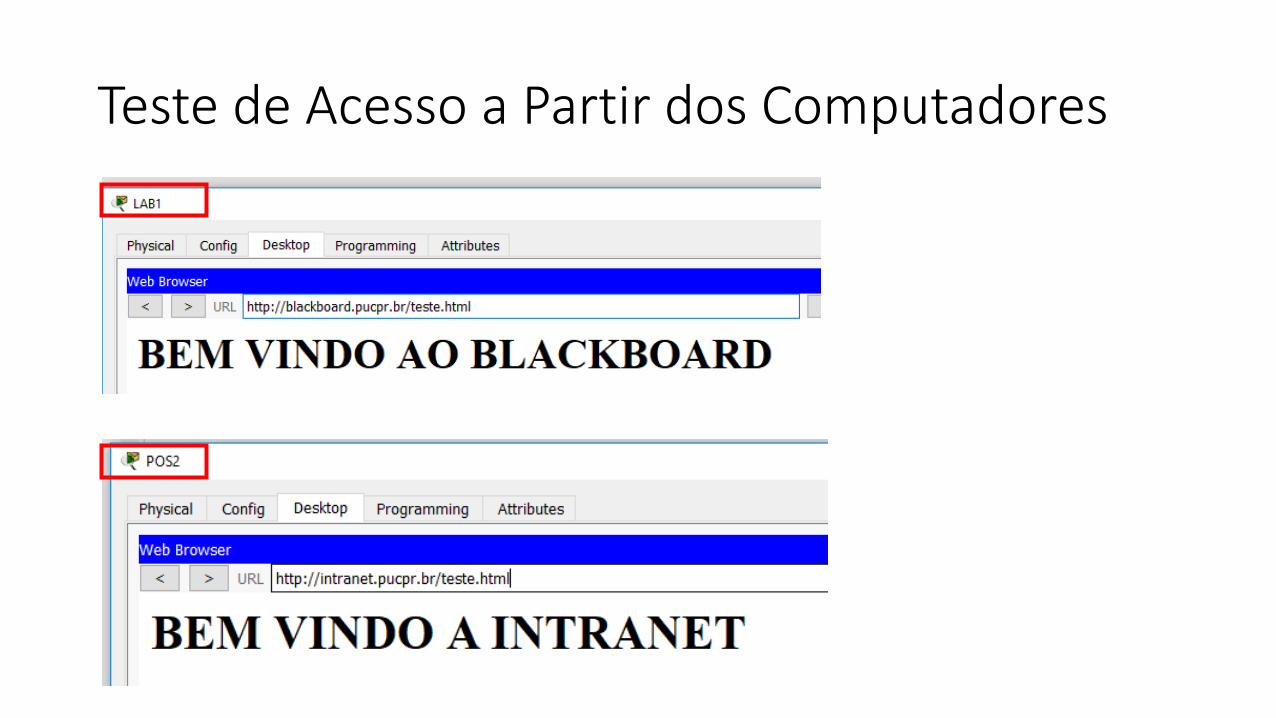
Teste de Acesso a Partir dos Computadores


![[1] Vencendo o Panico - Prof Bernard Range](https://img.document.onl/doc/110x75/577d24e81a28ab4e1e9dae64/1-vencendo-o-panico-prof-bernard-range.jpg)