Embed Size (px)
Citation preview
Benefícios de usinas reversíveis e aspectos técnico s do equipo electromecânico
SEMINÁRIO TÉCNICO SOBRE USINAS HIDRELÉTRICAS REVERSÍVEIS NO SETOR ELÉTRICO BRASILEIRO, 12/11/2014
Alois LechnerMichael SchmidPeter Magauer
^ ANDRITZ HYDRO Austria / Alemania
2
Benefícios de usinas reversíveis com controle de ve locidadeConteúdo
� Visão do sistema: velocidade fixa – velocidade variável
� Benefícios do controle de velocidade já implantados
� Carga variável no modo bomba
� Otimização da eficiência
� Transição rápida entre modo bomba para modo turbina
� Benefícios da velocidade variável a serem explorados
� Auxílio no controle instantâneo de potência
� Auxílio à inércia da rede
SEMINÁRIO TÉCNICO SOBRE USINAS HIDRELÉTRICAS, 12/11/2014 Alois Lechner

3
Arranjo de vel. fixa (“Fixa ”)
SEMINÁRIO TÉCNICO SOBRE USINAS HIDRELÉTRICAS, 12/11/2014 Alois Lechner
• Rede
• Transformador elevador
• Motor/Gerador(+ Excitação CC)
Turbina-bomba “Fixa”
Benefícios de usinas reversíveis com controle de ve locidadeVisão do Sistema
4
Arranjo de vel. variável com Gerador de Dupla Alimentação (“DFG”)
SEMINÁRIO TÉCNICO SOBRE USINAS HIDRELÉTRICAS, 12/11/2014 Alois Lechner
• Rede
• Transformador elevador
• Trafo do conversor
• Conversor
• Motor/Gerador
Turbina-bomba “Var”
Benefícios de usinas reversíveis com controle de ve locidadeVisão do Sistema
5
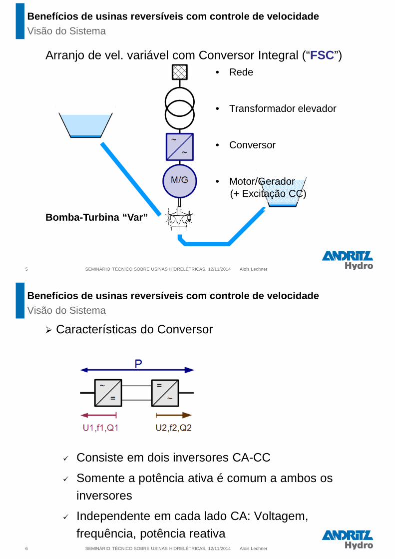
Arranjo de vel. variável com Conversor Integral (“FSC”)
SEMINÁRIO TÉCNICO SOBRE USINAS HIDRELÉTRICAS, 12/11/2014 Alois Lechner
• Rede
• Transformador elevador
• Conversor
• Motor/Gerador(+ Excitação CC)
Bomba-Turbina “Var”
Benefícios de usinas reversíveis com controle de ve locidadeVisão do Sistema
6
� Características do Conversor
� Consiste em dois inversores CA-CC
� Somente a potência ativa é comum a ambos os
inversores
� Independente em cada lado CA: Voltagem,
frequência, potência reativaSEMINÁRIO TÉCNICO SOBRE USINAS HIDRELÉTRICAS, 12/11/2014 Alois Lechner
Benefícios de usinas reversíveis com controle de ve locidadeVisão do Sistema

7
� Rendimento do sistema – operação como turbina
SEMINÁRIO TÉCNICO SOBRE USINAS HIDRELÉTRICAS, 12/11/2014 Alois Lechner
Benefícios de usinas reversíveis com controle de ve locidadeOtimização do rendimento
8
� Rendimento do sistema – operação como turbina
SEMINÁRIO TÉCNICO SOBRE USINAS HIDRELÉTRICAS, 12/11/2014 Alois Lechner
Benefícios de usinas reversíveis com controle de ve locidadeOtimização do rendimento

9
� Rendimento do sistema – operação como turbina
SEMINÁRIO TÉCNICO SOBRE USINAS HIDRELÉTRICAS, 12/11/2014 Alois Lechner
Benefícios de usinas reversíveis com controle de ve locidadeOtimização do rendimento
10
� Rendimento do sistema – operação como bomba
SEMINÁRIO TÉCNICO SOBRE USINAS HIDRELÉTRICAS, 12/11/2014 Alois Lechner
Benefícios de usinas reversíveis com controle de ve locidadeOtimização do rendimento

11
� Rendimento do sistema – operação como bomba
SEMINÁRIO TÉCNICO SOBRE USINAS HIDRELÉTRICAS, 12/11/2014 Alois Lechner
Benefícios de usinas reversíveis com controle de ve locidadeOtimização do rendimento
12
� Rendimento do sistema – operação como bomba
SEMINÁRIO TÉCNICO SOBRE USINAS HIDRELÉTRICAS, 12/11/2014 Alois Lechner
Benefícios de usinas reversíveis com controle de ve locidadeOtimização do rendimento
13
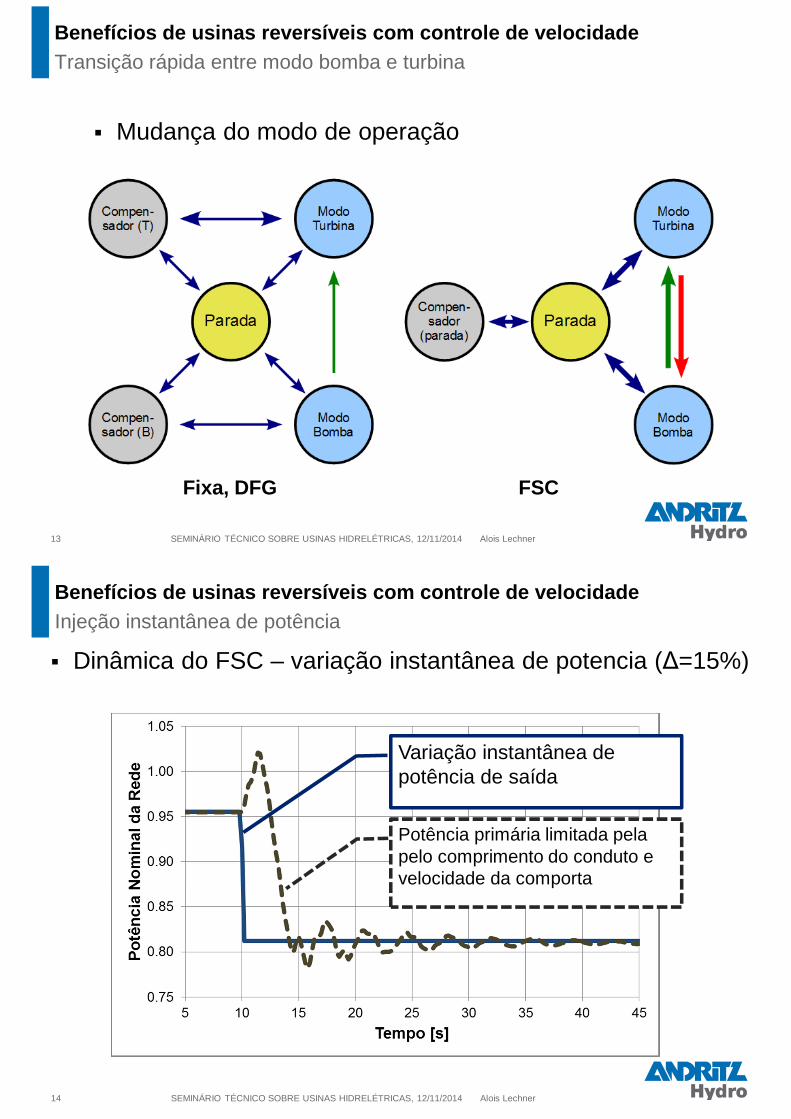
� Mudança do modo de operação
SEMINÁRIO TÉCNICO SOBRE USINAS HIDRELÉTRICAS, 12/11/2014 Alois Lechner
Fixa, DFG FSC
Benefícios de usinas reversíveis com controle de ve locidadeTransição rápida entre modo bomba e turbina
14
� Dinâmica do FSC – variação instantânea de potencia (∆=15%)
SEMINÁRIO TÉCNICO SOBRE USINAS HIDRELÉTRICAS, 12/11/2014 Alois Lechner
Variação instantânea de potência de saída
Potência primária limitada pela pelo comprimento do conduto e velocidade da comporta
Benefícios de usinas reversíveis com controle de ve locidadeInjeção instantânea de potência

SEMINÁRIO TÉCNICO SOBRE USINAS HIDRELÉTRICAS, 12/11 /2014 Alois Lechner
Inércia virtual do sistema = múltiplas inércias físicas
15
Benefícios de usinas reversíveis com controle de ve locidadeSustentação de inércia do sistema
SEMINÁRIO TÉCNICO SOBRE USINAS HIDRELÉTRICAS, 12/11 /2014 Alois Lechner
Inércia virtual do sistema = múltiplas inércias físicas
16
Benefícios de usinas reversíveis com controle de ve locidadeSustentação de inércia do sistema

SEMINÁRIO TÉCNICO SOBRE USINAS HIDRELÉTRICAS, 12/11 /2014 Alois Lechner
Inércia virtual do sistema = múltiplas inércias físicas
17
Benefícios de usinas reversíveis com controle de ve locidadeSustentação de inércia do sistema
SEMINÁRIO TÉCNICO SOBRE USINAS HIDRELÉTRICAS, 12/11 /2014 Alois Lechner
�Resultados das simulações de inércia do sistema
18
Benefícios de usinas reversíveis com controle de ve locidadeSustentação de inércia do sistema

SEMINÁRIO TÉCNICO SOBRE USINAS HIDRELÉTRICAS, 12/11 /2014 Alois Lechner
�Resultados das simulações de inércia do sistema
19
Benefícios de usinas reversíveis com controle de ve locidadeSustentação de inércia do sistema
20 SEMINÁRIO TÉCNICO SOBRE USINAS HIDRELÉTRICAS, 12/11/2014 Alois Lechner
� O subsídio do governo a energia fotovoltaica na
Alemanha arruinou o retorno dos projetos de PSP,
sendo que a maioria dos projetos europeus de PSP
estão “on hold”.
� Os novos projetos pendentes buscam flexibilidade total
� Configuração FSC
� A Irlanda, vulnerável a problemas de estabilidade,
planeja recompensar o fornecimento de inércia ao
sistema.
Benefícios de usinas reversíveis com controle de ve locidadeSumário e Conclusão

Motor-Generator – engineering highlightsSEMINÁRIO TÉCNICO SOBRE USINAS HIDRELÉTRICAS REVERSÍVEIS
NO SETOR ELÉTRICO BRASILEIRO
12/11/2014Michael Schmid, Dipl.Ing., MBA
Different Pump-Storage concepts
Variable speed Motor-Generator
MG-References
22 www.andritz.com
Content
Motor-Generator Technology
23 www.andritz.com
speed
pump storage power plants
fixed speed variable speedfixed speed
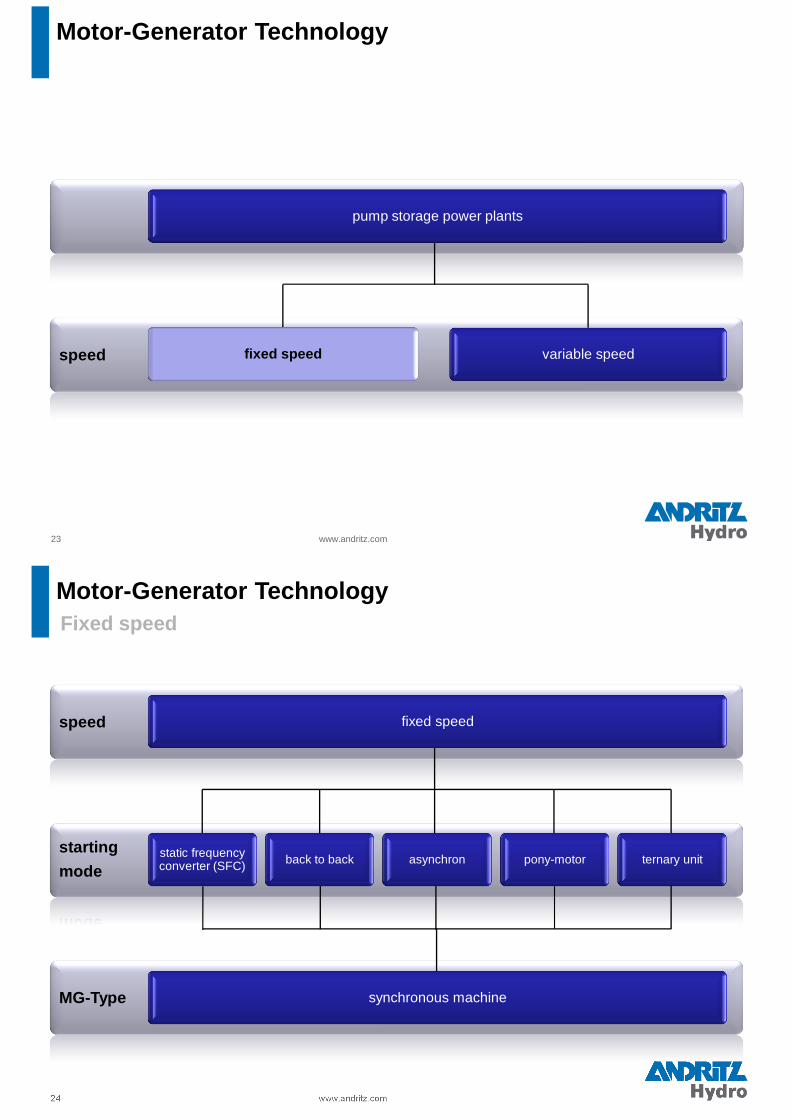
Motor-Generator Technology
Fixed speed
24 www.andritz.com
MG-Type
starting
mode
speed fixed speed
back to backstatic frequency converter (SFC) asynchron pony-motor ternary unit
synchronous machine
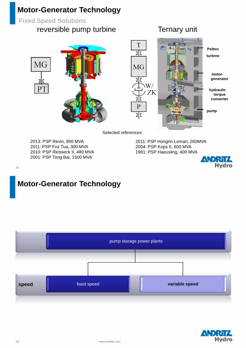
Motor-Generator Technology
25
Selected references:
2013: PSP Revin, 800 MVA2011: PSP Foz Tua, 300 MVA2010: PSP Reisseck II, 480 MVA2001: PSP Tong Bai, 1500 MVA
reversible pump turbine Ternary unit
Pelton
turbine
motor-generator
hydraulic torque
converter
pump
2011: PSP Hongrin Leman, 260MVA2004: PSP Kops II, 600 MVA1981: PSP Haeusling, 400 MVA
Fixed Speed Solutions
Motor-Generator Technology
26 www.andritz.com
speed
pump storage power plants
fixed speed variable speedvariable speed
Motor-Generator Technology

Variable speed
27 www.andritz.com
MG-Type
starting
mode
speed variable speed
converter in the stator circuit –
Full size Converter (FSC)converter in the rotor circuit
all kinds of Motor Generators are possible
doubly fed asynchronous machine
(DFM)
Motor-Generator Technology
28
Rotor PSP Goldisthal
Link machine speed/grid frequency
)1(60
sp
fn −⋅⋅=
f stator voltage frequency in Hzn machine speed in rpmp number of pole pairss slip (zero for synchrounos machines)
⇒ two concepts:
• converter in rotor circuit (double fed motor-generator)
• converter in stator circuit (full size converter)
Electric system - Principle
www.andritz.com
Motor-Generator Technology

29
Doubly Fed Motor-Generator - dimension
Comparison of dimensions of Motor-Generator – example GOLDISTHAL
Synchronous Motor-Generator Variable Speed Motor-Generator
www.andritz.com
Motor-Generator Technology
30
Doubly Fed Motor-Generator – comparison
Comparison between FIX speed Synchronous and VARIABLE speed Double Fed Motor-Generators applied in Pumped Storage Plants
Synchronous Machine
� Rotor equipped with DC field windings and
2 slip rings
� Rotor field is fixed coupled with the rotor
position
� Rotor field can only be varied in magnitude
and not in position
� Simple DC excitation equipment
Double Fed Motor-Generator
� Rotor equipped with 3-phase winding system
and 3 slip rings
� Rotor field is decoupled from the rotor position
� Decoupled control of real and reactive power
is possible
� Converter for 4-Q operation connected
between rotor-circuit and generator bus duct
Motor-Generator Technology

www.andritz.com
Doubly Fed Motor-Generator – Comparison
Motor-Generator Technology
www.andritz.com
Doubly Fed Motor-Generator – Comparison
Shrink-on retaining ring design
+ approved (reference proj.: Goldisthal)
+ quick assembly
+ few parts of end winding support (approx. 2.300, incl. aluminum cooling profiles)
+ no radial compression forces on bars
+ low air friction losses
o indirect cooling of bars via aluminum profiles
- more costly solution
U-bolt design
+ less costly solution
+ easy assembly
+ simple parts, easy to manufacture
o cooling of bars due to direct convection
- high air friction losses
- radial compression forces on bars
- time-consuming assembly
- high number of parts of end winding support(approx. 19.000)
Motor-Generator Technology
References
33 www.andritz.com
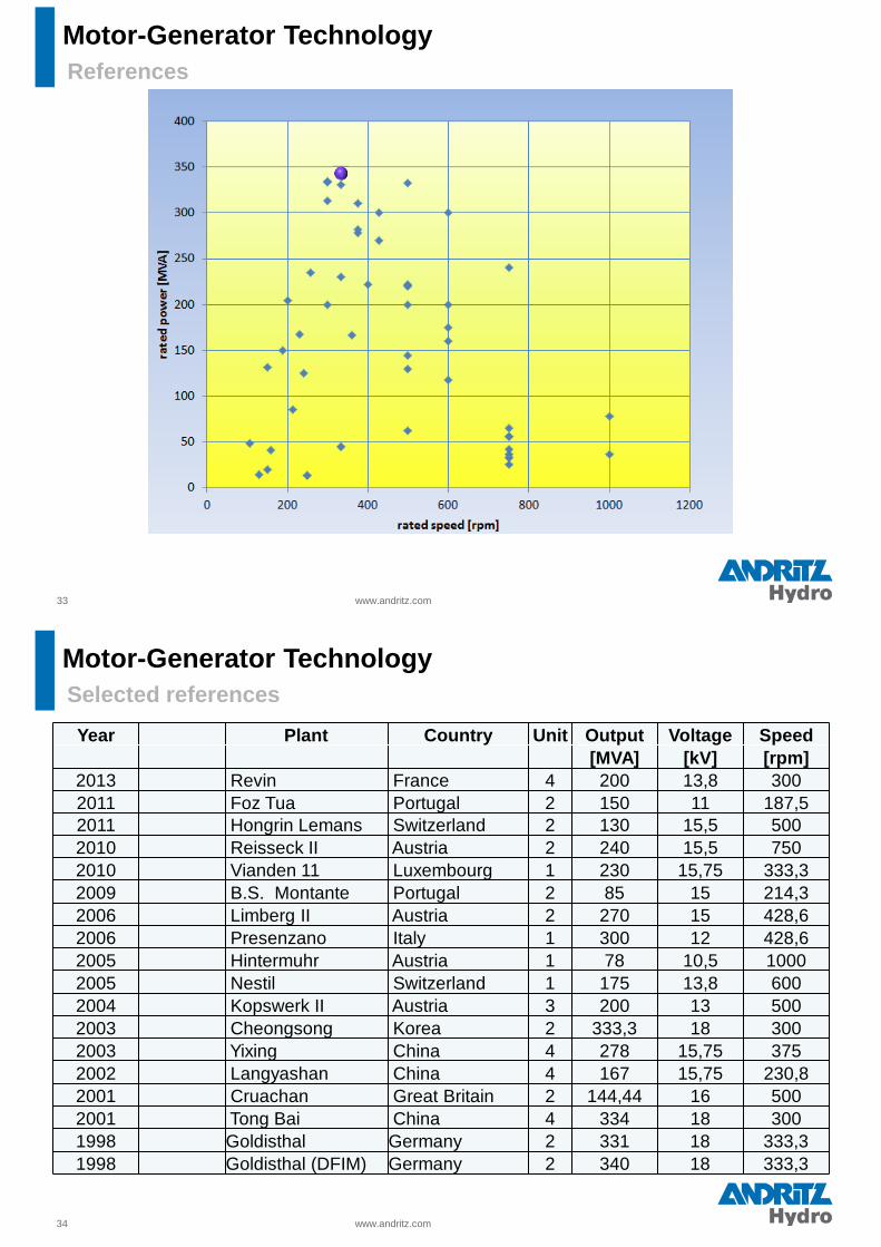
Motor-Generator Technology
34 www.andritz.com
Selected references
Year Plant Country Unit Output Voltage Speed[MVA] [kV] [rpm]
2013 Revin France 4 200 13,8 3002011 Foz Tua Portugal 2 150 11 187,52011 Hongrin Lemans Switzerland 2 130 15,5 5002010 Reisseck II Austria 2 240 15,5 7502010 Vianden 11 Luxembourg 1 230 15,75 333,32009 B.S. Montante Portugal 2 85 15 214,32006 Limberg II Austria 2 270 15 428,62006 Presenzano Italy 1 300 12 428,62005 Hintermuhr Austria 1 78 10,5 10002005 Nestil Switzerland 1 175 13,8 6002004 Kopswerk II Austria 3 200 13 5002003 Cheongsong Korea 2 333,3 18 3002003 Yixing China 4 278 15,75 3752002 Langyashan China 4 167 15,75 230,82001 Cruachan Great Britain 2 144,44 16 5002001 Tong Bai China 4 334 18 3001998 Goldisthal Germany 2 331 18 333,31998 Goldisthal (DFIM) Germany 2 340 18 333,3
Motor-Generator Technology

www.andritz.com
New Pumped Storage Power Plant - extension to existi ng HPP
Scope of Supply:
• One reversible Pumpturbine, 70 MW
• Rotary valves and gate
• Reversible Motorgenerator(78 MVA, 10.5 kV, 1.000 rpm)
• Excitation Equipment
• MV-Switchgear incl. Busduct
• SFC 2.9 MW
• Automation, Protection and
Control Equipment
• Implementation of existing station service
Commissioning: 2007
Hintermuhr - Austria
Complete E&M Equipment
Motor-Generator Technology
www.andritz.com
Main Equipment:� 1 x 142 MW 4-stage
reversible Pumpturbine,� 1 x 175 MVA Motorgenerator,
start up Pelton� Net Head 858..1066 m� 600 rpm
Project Highlights� Extreme pumping head requires use
of multi-stage pump
Commissioning: 2009
Tierfehd / Switzerland
Turnkey - Complete E&M Equipment
Motor-Generator Technology

www.andritz.com
First speed variable Pumped Storage Plant
in Europe
Goldisthal / Germany
Customer:� Vattenfall
Motor Generator� 2x340 MVA DFIM and
2x331 MVA fixed speed M/G, AC Excitation and Starting - SFC
� 300..346 rpm and 333 rpm
Project Highlights� two sets of synchronous and
doubly fed asynchronous M/G� Central location in the UCTE grid
Commissioning: 2003
PSW Goldisthal 1060 MW
Motor-Generator Technology
Reißeck II / Austria
14.11.2014 www.andritz.com
Main Technical Data
� 2 Units
� S = 240 MVA
� Un = 15,5 kV
� n = 750 r.p.m. (8 poles)
� Runaway speed = 1142 r.p.m.
� Overspeed test = 1200rpm
� currently under commissioning
Expected date of completion: 2014
Motor-Generator Technology

Pole surface speed at rated speed 450 km/h
Pole surface speed at overspeed 724 km/h
Mass of one pole 9.100 kg
Centrifugal force of one pole at rated speed 7.800 t
Centrifugal force of one pole at overspeed 20.000 t
14.11.2014 39
www.andritz.com
Reißeck II / Austria
Motor-Generator Technology
� Geometrie of poles and pole fixing
ANSYS 12.1 and 13
Verification of fatigue strength with FKM method co nsidering
6 start / stops a day,
6 load rejections yearly,
Safety margin of 2 for stress level
Lifetime > 70 years
ComponentRe(MPa)
Lifetime (Years)
Rotor hub 800 > 100
Pole end plate 800 84
Pole sheet 550 > 100
Comb bolts 850 > 100
14.11.2014 www.andritz.com
Reißeck II / Austria
Motor-Generator Technology

41 The copyright of this document and all attachments remains with the company
Pump Turbine TechnologyContent
1) Changing requirementsfor equipment design
2) The classical concept: Fixed speed single stagereversible pump turbine
Design characteristics
Recent examples
3) Special configurations
Variable Speed
Ternary sets, Hydraulic short circuit
Multi Stage Pump Turbines
Sea Water Pumped Storage
05/2
012
Increasing variety and complexity of requirements for equi pment:
42
� Frequent load changes All Hydro Turbines
� Frequent start / stops Storage / Pumped storage plants
� Wide operation range Francis, Pump TurbinesStability over a wide range Pump Turbines
� Fast changeover times Pump Turbines
� Safe Operation, robust design All Hydro Turbines
� High efficiencies All Hydro Turbines
� Cost optimized dimensions/design All Hydro Turbines
� Environmental aspects All Hydro Turbines
Pump Turbine TechnologyChanging requirements for Hydroelectric equipment
The copyright of this document and all attachments remains with the company

05/2
012
43
� Much more part load operation� Much more Start-Stop events� Dynamic stresses drastically
increased
CFD / FEM AnalysesVerification by prototype measurementsEstimation of lifetime for criticalcomponentsInvestigations currently for all 4 turbine types
Frequent Start – StopsOperation over full range
Measured blade stress
Startup/SNL full load SNL
Pump Turbine TechnologyEquipment Requirements
The copyright of this document and all attachments remains with the company
05/2
012
44
Research on Unsteady Phenomena in Pump turbines
Pump stability at high head� Drop of head-flow characteristics at high
heads� Unstable operation or start-up possible ?
The behavior will be stable for a negative slope of the characteristic curve at the operating point, but for a positive slope the behavior will be unstable.
From P. Dörfler, M. Sick, A. Coutu. Flow-Induced Pulsation and Vibration in Hydroelectric Machinery. Springer Verlag (2013). Chapter 6.4.2
Pump Turbine TechnologyEquipment Requirements
The copyright of this document and all attachments remains with the company

05/2
012
45
Layout always is a compromise between several aspects� High efficiencies over a wide range� Safety against cavitation damage� Dimensions and geometry favourable for manufacturing and c ost� Impact on civil works (dimensions, setting level)� Stability� Robustness
Especially on Pump turbines, Robustness is crucial.
Pump Turbine TechnologyEquipment Requirements
The copyright of this document and all attachments remains with the company
example: adjustablewicket gate bearings���� lower vibration level
05/2
012
46
Pump Turbine TechnologyThe classical concept
Single stage, reversible,fixed speed Pump Turbine
Pump starting with SFC in dewatered condition
Often with Synchronouscondenser mode(Labyrinth cooling!)
Earlier NowDay / Night FrequentCycle part load
Changeover times 7-8 min 5-6 min(Fast changeover PUMP � TUR ~ 90 sec exeptional - very rough condition!)
Double peak test
The copyright of this document and all attachments remains with the company

05/2
012
47
avoid:pit diameterreduction needsa split headcover(not valid for middledismantling)
include:prestressedbearings
include:partly concretearound drafttube cone
avoid:Shearpins
include:segment type radial bearing
include:access to lowerwicket gatebearing
include:axial hydrostaticshaft seal
Typical design features for a reversible Pump turbine
Prefer:Individual servomotors forGuide vanes
Pump Turbine TechnologyThe classical concept – Design features
The copyright of this document and all attachments remains with the company
05/2
012
48
Pump Turbine TechnologyReversible Pump Turbine – Recent examples
The copyright of this document and all attachments remains with the company
Customer: SEO / RWE
1 Pump turbine 200 MW
D1 = 4400 mm H = 300 m
Contract year: 2010Second extension of the existingPumped storage plant
ANDRITZ Hydro Scope: Pump turbine, Motor generator
Vianden
Unit 11
Luxemburg

05/2
012
Baixo Sabor MontantePortugal
49
Customer: EDP
Runner Diameter 4112 mm
Head range H = 68.8 m – 104.6 m
Max power P = 76.9 MW
Speed n = 214.29 rpm
Scope of supply:
2 Pump Turbines
Motor/Generators
Auxiliary equipment
Wide head variation
Equipped with ring gate
Pump Turbine TechnologyReversible Pump Turbine – Recent examples
The copyright of this document and all attachments remains with the company
05/2
012
50
Baixo Sabor JusantePortugal
Customer: EDP
Runner Diameter D1 3948 mm
Head range H 26.2 m – 35.2 m
Max. power P 17.8 MW
Speed 150 rpm
Scope of supply:
2 Pump Turbines
Motor/Generator
Auxiliary equipment
Pump Turbine TechnologyReversible Pump Turbine – Recent examples
The copyright of this document and all attachments remains with the company

05/2
012
Large Hydro
Foz Tua
Portugal
2 Pump turbines 124 MWH = 96 mD = 3460 mmN = 187 rpm
Motor generators, Penstock, gates
Electrical power Systems
Cranes, Auxiliaries
Equipped with ring gate
Contract: November 2011
Model test,
adaptation to increased operating range
Portugal
The copyright of this document and all attachments remains with the company
05/2
012
52
New concept for standardized solution
� Reduced project specific cost (engineering, assembly, …)
� No individual model test
� Standardized equipment
� Simple installation
� Variable Speed, Full size Converter
� Competitive W2W solution
High head applications:
Multi stage pump withseparate Pelton Turbine
Standardization
Range:
5 – 50 MW / unit
25 – 250 m Head
The copyright of this document and all attachments remains with the company
Pump Turbine TechnologyStandardized concept

05/2
012
53
max. head
min. head
max. speed
min. speed
cavitation limit,high pressure side
cavitation limit,low pressure side
stability limit
Variable speed unitshave a substantiallywider operating rangeboth in Turbine andPump mode
BUT: Even with FullSize Converter,- Hydraulic limits
must be con-sidered (cavitation, stability)
- High flexibility effectonly with regulatedturbines (guidevanes, speed)
The copyright of this document and all attachments remains with the company
Pump Turbine TechnologyVariable Speed Units
05/2
012
54
Maximum flexibility byHydraulic Short Circuit
to tailwater
Hydraulic short circuitPartly to tailwater, partly to pump
To and from headwater
Hydraulic short circuitPartly to headwater, partly to turbine
from tailwater
Example: Kops II / Austria
The copyright of this document and all attachments remains with the company
Vertical or horizontal shaft
Pump Turbine TechnologyTernary Units
Obervermunt II (2x180 MW)

05/2
012
Client: Vorarlberger IllwerkeUnique Ternary concept
Pressurized downstream chamber
In operation since 2009
3 x 180 MW Tu / 150 MW Pu / 826 m
Full load in 20-30 s (Tu and Pu mode)
> 8000 operating hours / year!
Pump Turbine TechnologyTernary Units
Typical operation curve over 12hoursPUMP
TUR
Hydraulic TorqueConverter allows maximum flexibility
The copyright of this document and all attachments remains with the company
Source: P. Matt, Vorarlberger Illwerke, Sep 2014, Porto
Kops II Austria
05/2
012
56
Two stage reversible units: 2 regulateddistributors ����flexibilityin turbine modeFor heads < 1000m Smaller dimensions thanternary sets
The copyright of this document and all attachments remains with the company
Pump Turbine TechnologyMulti Stage Pump Turbines
Shop assembly in Ravensburg
Tierfehd (Nestil), Switzerland
Customer: AXPO
1 four stagereversible
Pump turbine, MIV,motor generator
P = 130 MW
H = 1062 m
n = 600 rpm
Contract year: 2005
For high headsNo part load operationFlexibility only ifcombined in a ternaryset

05/2
012
57
Projects are promoted with sea water PSP. One pilot plant in Japan exists.
PRO CONTRA
Saving of Downstream Reservoir Stainless steel for turbin e partsAustenitic steel - Lower blade
Additional sites possible strength ���� bigger unitsCorrosion resistant penstock
No evaporation problem Gates subject to high corrosion
Projects in dry hot , areas will Salt water in headpon d may createanyway need desalination environmental problemsor salt content grows Marine life in water circuit (cooling…)
Increased maintenance & repairCathodic protection system
Possible to build, BUT: Substantial additional cost !
We consider the economic benefit of sea water PSPs question able
The copyright of this document and all attachments remains with the company
Pump Turbine TechnologySea water applications
05/2
012
Comparison for more than one unit
58 www.andritz.com
Fixed speed Variable speed
ReverisblePump-Turbine
Ternary unit
DFM(Doubly fed
asynchronousMG)
FSC (salient pole MG with a full size
converter)system efficiency T: P: T: P: T: P:control range (Power +/-100% output)mode change times
Grid
stab
ility
reaction time on failure(frequency changes)power factor adoption(voltage changes in the
grid)
synchronous condensermode
rotatinghydraulicmachine
rotatinghydraulicmachine
rotating hydraulicmachine
in standstill
space requirements(Volume)
100% 150%-200% 115%-125% 130%-140%
world wide references >300 only a few >101 in hydrobusiness
costs of the E&Mequipment
100% 120%-140% 115% - 130% 150-170%
worseMiddleAlmost bestbest

05/2
012
Obrigadopara su
atenção !
59 www.andritz.com
Alois Lechner
ANDRITZ HYDRO GmbHEibesbrunnergasse 201120 Vienna, AUSTRIA
[email protected]: +43 664 8330948
Michael Schmid
ANDRITZ HYDRO GmbHEibesbrunnergasse 201120 Vienna, AUSTRIA
[email protected]:+43 664 9614516
Peter Magauer
ANDRITZ HYDRO GmbHEscher-Wyss-Weg 1
Ravensburg, [email protected]
Mobile: +49 173 5623522