Embed Size (px)
Citation preview

Catalogo Tecnico 20172017 Technical Catalogue
riscaldamentoINDUSTRIALEi n d u s t r i a lH E A T I N G


SOLUZIONI ENERGETICHE PER IL TUO BUSINESS
ENERGY SOLUTION FOR YOUR BUSINESS
riscaldamentoINDUSTRIALEi n d u s t r i a lH E A T I N G
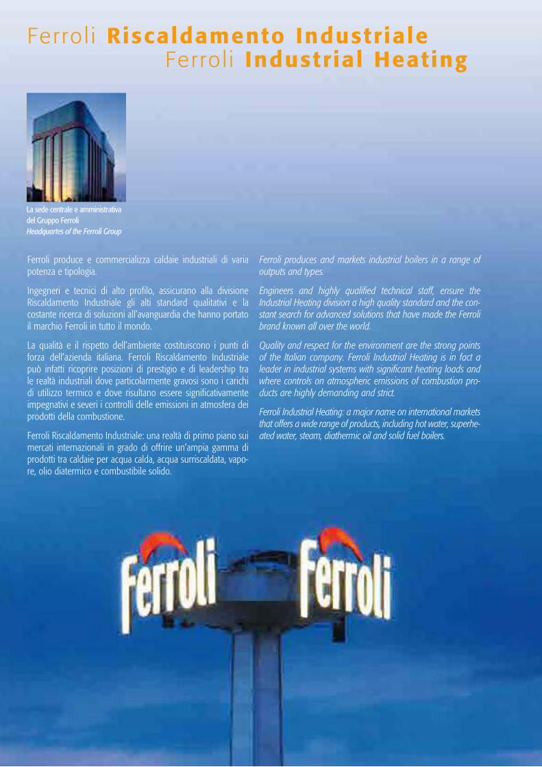
La sede centrale e amministrativa del Gruppo FerroliHeadquartes of the Ferroli Group
Ferroli produce e commercializza caldaie industriali di varia potenza e tipologia.
Ingegneri e tecnici di alto profilo, assicurano alla divisione Riscaldamento Industriale gli alti standard qualitativi e la costante ricerca di soluzioni all’avanguardia che hanno portato il marchio Ferroli in tutto il mondo.
La qualità e il rispetto dell’ambiente costituiscono i punti di forza dell’azienda italiana. Ferroli Riscaldamento Industriale può infatti ricoprire posizioni di prestigio e di leadership tra le realtà industriali dove particolarmente gravosi sono i carichi di utilizzo termico e dove risultano essere significativamente impegnativi e severi i controlli delle emissioni in atmosfera dei prodotti della combustione.
Ferroli Riscaldamento Industriale: una realtà di primo piano sui mercati internazionali in grado di offrire un’ampia gamma di prodotti tra caldaie per acqua calda, acqua surriscaldata, vapo-re, olio diatermico e combustibile solido.
Ferroli produces and markets industrial boilers in a range of outputs and types.
Engineers and highly qualified technical staff, ensure the Industrial Heating division a high quality standard and the con-stant search for advanced solutions that have made the Ferroli brand known all over the world.
Quality and respect for the environment are the strong points of the Italian company. Ferroli Industrial Heating is in fact a leader in industrial systems with significant heating loads and where controls on atmospheric emissions of combustion pro-ducts are highly demanding and strict.
Ferroli Industrial Heating: a major name on international markets that offers a wide range of products, including hot water, superhe-ated water, steam, diathermic oil and solid fuel boilers.
Ferro l i Riscaldamento Industriale Fer ro l i Industrial Heating
5
Riscaldatoriad olio
diatermicoDiathermic oil heaters
La gammaprodotti
Product range
Caldaie a combustibile solidoSolid fuel boilers
Generatori perla produzione
di vaporeSteam generators
Caldaie ad acquacalda e acquasurriscaldata
Hot water boilers and superheated
water boilers
AccessoriAccessories
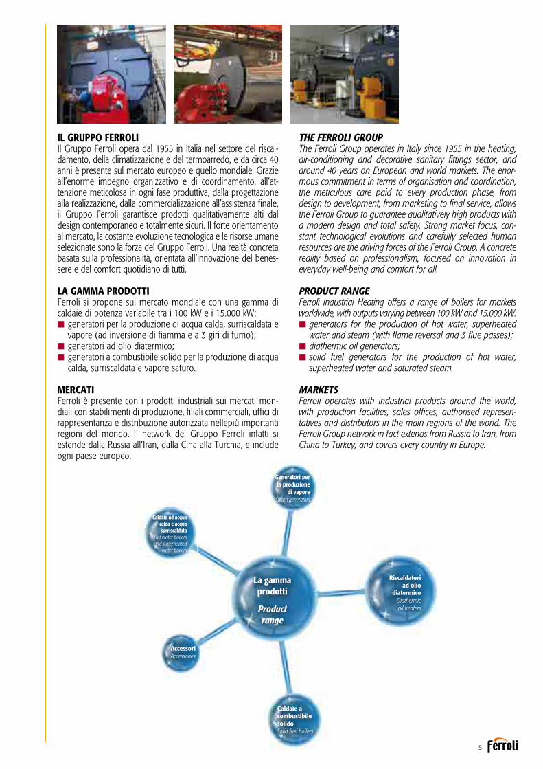
THE FERROLI GROUPThe Ferroli Group operates in Italy since 1955 in the heating, air-conditioning and decorative sanitary fittings sector, and around 40 years on European and world markets. The enor-mous commitment in terms of organisation and coordination, the meticulous care paid to every production phase, from design to development, from marketing to final service, allows the Ferroli Group to guarantee qualitatively high products with a modern design and total safety. Strong market focus, con-stant technological evolutions and carefully selected human resources are the driving forces of the Ferroli Group. A concrete reality based on professionalism, focused on innovation in everyday well-being and comfort for all.
PRODUCT RANGEFerroli Industrial Heating offers a range of boilers for markets worldwide, with outputs varying between 100 kW and 15.000 kW:ngenerators for the production of hot water, superheated
water and steam (with flame reversal and 3 flue passes);ndiathermic oil generators;nsolid fuel generators for the production of hot water,
superheated water and saturated steam.
MARKETSFerroli operates with industrial products around the world, with production facilities, sales offices, authorised represen-tatives and distributors in the main regions of the world. The Ferroli Group network in fact extends from Russia to Iran, from China to Turkey, and covers every country in Europe.
IL GRUPPO FERROLIIl Gruppo Ferroli opera dal 1955 in Italia nel settore del riscal-damento, della climatizzazione e del termoarredo, e da circa 40 anni è presente sul mercato europeo e quello mondiale. Grazie all’enorme impegno organizzativo e di coordinamento, all’at-tenzione meticolosa in ogni fase produttiva, dalla progettazione alla realizzazione, dalla commercializzazione all’assistenza finale, il Gruppo Ferroli garantisce prodotti qualitativamente alti dal design contemporaneo e totalmente sicuri. Il forte orientamento al mercato, la costante evoluzione tecnologica e le risorse umane selezionate sono la forza del Gruppo Ferroli. Una realtà concreta basata sulla professionalità, orientata all’innovazione del benes-sere e del comfort quotidiano di tutti.
LA GAMMA PRODOTTIFerroli si propone sul mercato mondiale con una gamma di caldaie di potenza variabile tra i 100 kW e i 15.000 kW:n generatori per la produzione di acqua calda, surriscaldata e
vapore (ad inversione di fiamma e a 3 giri di fumo);n generatori ad olio diatermico;n generatori a combustibile solido per la produzione di acqua
calda, surriscaldata e vapore saturo.
MERCATIFerroli è presente con i prodotti industriali sui mercati mon-diali con stabilimenti di produzione, filiali commerciali, uffici di rappresentanza e distribuzione autorizzata nellepiù importanti regioni del mondo. Il network del Gruppo Ferroli infatti si estende dalla Russia all’Iran, dalla Cina alla Turchia, e include ogni paese europeo.

La produzione Production
Certificata ISO 9001 dal TÜV SUD, Ferroli opera all’interno di un’area produttiva di 20 mila metri quadrati ove sorge lo stabili-mento, gli uffici tecnici e di progettazione e il centro direzionale-commerciale delle caldaie industriali.
Ferroli lavora nell’ottica del “progetto”: grazie a un team di profes-sionisti in grado di soddisfare le esigenze dei clienti, alle migliori tecnologie impiegate nei reparti produttivi e all’utilizzo di materiali e processi conformi agli standard EN, tutti i prodotti sono certificati CE e omologati in diversi Paesi stranieri.
La flessibilità produttiva degli stabilimenti Ferroli permette all’a-zienda di soddisfare le più diverse esigenze del mercato, dal semplice impianto di riscaldamento a sofisticate centrali termiche per teleriscaldamenti e a servizio d’impianti produttivi.
Tecnici specializzati sono abilitati ai controlli non distruttivi di 2° livello (ultrasuoni, raggi X, liquidi penetranti) e ai vari procedimenti di saldatura, secondo le norme EN che coprono la totalità delle sal-dature previste, tra cui la saldatura in arco sommerso, tig, saldatura con elettrodi basici e saldatura con fili animati.
Gli investimenti effettuati hanno permesso un elevato grado d’automazione nelle aree di taglio e saldatura.
RISPARMIO ENERGETICOQUALITÀ E RENDIMENTOL’attuale situazione del mercato energetico nazionale e interna-zionale richiede costante attenzione per ottenere e mantenere elevati rendimenti termici.I generatori infatti sono progettati con elevate superfici di scam-bio termico e dotati di recuperatori ed economizzatori.Queste caratteristiche innalzano di molto le percentuali di ren-dimento e al contempo riducono sensibilmente sia le perdite termiche che i costi di esercizio.I sistemi Ferroli inoltre esercitano un basso impatto ambientale soddisfando anche le più restrittive normative in termini di emissioni in atmosfera e parametri d’efficienza.
Ferroli is ISO 9001 certified by TÜV SUD and operates in produc-tion facilities covering twenty thousand square metres, including the factory, technical and design offices and management-sales departments of industrial boilers.
Ferroli adopts a “project” approach: a team of professionals that can satisfy all customer needs, the best technology applied in the production department and the use of materials and processes compliant with EN standards mean that all products are CE marked and approved in various foreign countries.
The manufacturing flexibility of the Ferroli facilities allows the company to respond to a vast variety of market demands, from simple heating systems to sophisticated installations for district heating and serving production plants.
Specialist engineers and technicians conduct level two non-destructive testing (ultrasound, X rays, liquid penetrants) and various welding procedures qualified according to the standards EN involving all the welding featured in our projects, including submerged arc and TIG welding, welding with basic electrodes and flux-cored welding.
The investments made have allowed a high level of automation to be reached in the cutting and welding process.
ENERGY SAVINGS, QUALITY AND EFFICIENCYThe current national and international energy market situation requires constant attention in order to achieve and maintain high efficiency in the use of thermal energy.Our generators are designed with large heat exchange surfaces and are fitted with heat recovery units and economisers. These features considerably increase efficiency and at the same time significantly reduce both heat loss and running costs.The Ferroli systems also have a low environmental impact, com-plying with even the strictest standards in terms of atmospheric emissions and efficiency parameters.

7
TECHNOLOGY AND RESEARCHTechnology, research and special care paid to quality are the elements that define the entire manufacturing procedure of the Industrial Heating Division.Ferroli implements an advanced design system, with a 3D drawing program, selects very high quality raw materials and accessories, and pays meticulous care to every phase in construction, using specialist personnel with proven experience and the most modern cutting and welding equipment.
Intelligent and effective management of the entire heating plant is one of the crucial aspects of all modern companies that want to rationally exploit the heat generated by their boilers. Therefore, it has been developed a microprocessor-based remote control system - B.E.C.S. - that allows control from a distance, including display and saving of all key operating parameters, as well as remote control from our customer service centre.
MADE TO ORDER PRODUCTSFerroli offers custom solutions that satisfy the requirements of even the most demanding customers.Each individual order is examined by a team of technicians, that together with the customer looks for the most suitable solution. Upon request we can offer “turnkey” solutions, sup-plying, together with the generator, the entire heating plant with all the required components included control and boilerrunning systems for exemption 24h/72h.Specialist Service technicians guarantee correct installation, commissioning and calibration of the generator all over the world, as well as technical service and support.
TECNOLOGIA E RICERCALa tecnologia, la ricerca e la particolare attenzione alla qualità sono gli elementi che caratterizzano l’intera filiera produttiva della Divisione Riscaldamento Industriale.Ferroli implementa un sistema di progettazione avanzato con programma di disegno in 3D, sceglie materie prime e acces-sori di altissima qualità, e cura minuziosamente ogni fase costruttiva, potendo disporre di personale specializzato con comprovata esperienza e delle più moderne apparecchiature di taglio e saldatura.
Una gestione intelligente ed efficace dell’intero impianto termico, è uno dei punti cardine di tutte le aziende moderne che vogliono sfruttare razionalmente il calore prodotto dalle proprie caldaie.È stato pertanto sviluppato un sistema di controllo remoto a microprocessore - B.E.C.S. - che permette i controlli a distan-za, la visualizzazione e memorizzazione di tutti i parametri chiave di funzionamento, nonchè il telecontrollo da parte del nostro centro assistenza clienti.
PRODOTTI SU MISURAFerroli propone soluzioni personalizzate per soddisfare le richieste della clientela anche più esigente.Ogni singola commessa viene esaminata da un team di tec-nici che insieme al cliente ricerca la soluzione più adeguata. Su richiesta vengono offerte soluzioni “chiavi in mano” fornendo oltre al generatore anche l’intera centrale termica con tutti i suoi componenti compresi i sistemi di controllo e gestione caldaia per esenzione 24h/72h.I tecnici del Service specializzati garantiscono in tutto il mondo la corretta installazione, la messa in servizio e la tara-tura del generatore, nonché le attività di service e assistenza.
La qualità come f i losof ia Quality as phi losophy
Certificazioni ed omologazioni Italia ed Estero | Certifications and approvals of Italian and Foreign divisions
ISO 3834 Part 2Certificate n°2/IT/115

Caldaie a condensazione | Condensing boilers
npag. 24 NGT/RSW HH npag. 32 NG3/RSH HHH 92 - 1.890 kW/ 80 - 1.300 kWCaldaia per acqua calda a tre giri di fumo di cui due in camera di combustione.
Hot water boiler with three flue passes, two in furnace.
npag. 64
PREX N ASH160 - 3.500 kWCaldaia per acqua surriscaldata fino a 200°, a tre giri di fumo di cui due in camera di combustione.
Superheated water boiler max temperature 200°, with three flue passes, two in furnace.
npag. 68 PREXTHERM T3G F ASL npag. 76 PREXTHERM T3G F ASH1.200 - 9.000 kWCaldaia per acqua surriscaldata,a tre giri effettivi di fumo.
Superheated water boiler, with three flue passes.
npag. 72 PREXTHERM T3G N ASLnpag. 80 PREXTHERM T3G N ASH 6.000 - 15.000 kWCaldaia per acqua surriscaldata,a tre giri effettivi di fumo.
Superheated water boiler,with three flue passes.
Indice prodott i | Index
npag. 88 VAPOPREX LVPqnpag. 92 VAPOPREX LVP150 - 4.000 kg/h Generatore di vapore a bassa pressione a tre giri di fumo di cui due in camera di combustione.
Low pressure steam boiler withthree flue passes, two in furnace.
npag. 10
QUADRISTAR B HHHH 70 - 320 kWGruppo termico in acciaioa condensazione
Condensing boiler
npag. 14
QUADRISTAR B MODULARE HHHH 140 - 960 kWGruppo termico in acciaioa condensazione
Condensing boiler
npag. 28 NGT/RSW HH npag. 36 NG3/RSH HHH 2.360 - 6.000 kW / 1.600 - 3.000 kWCaldaia per acqua calda a tre giri di fumo di cui due in camera di combustione.
Hot water boiler with three flue passes, two in furnace.
npag. 44
PREXTHERM T3G F 1.200 - 9.000 kWCaldaia per acqua calda a tre giri effettivi di fumo.
Hot water boiler with three flue passes.
npag. 40
TP3 LN HHH70 - 3.200 kWCaldaia per acqua calda a tre giri effettivi di fumo - LOW NOx.
Hot water boiler with three flue passes - LOW Nox.
npag. 48
PREXTHERM T3G N 6.000 - 15.000 kWCaldaia per acqua calda a tre giri effettivi di fumo.
Hot water boiler with three flue passes.
npag. 96 VAPOPREX HVPqnpag. 100 VAPOPREX HVP150 - 5.000 kg/hGeneratore di vapore a media pressione a tre giri di fumo di cui due in camera di combustione.
Medium pressure steam boiler withthree flue passes, two in furnace.
npag. 108
VAPOPREX 3GF 1.600 - 7.600 kg/hGeneratore di vapore a media pressione a tre giri effettivi di fumo.
Medium pressure steam boilerwith three flue passes.
npag. 104
VP 3G 700 - 4.000 kg/hGeneratore di vapore a media pressione a tre giri effettivi di fumo.
Medium pressure steam boilerwith three flue passes.
npag. 112
VAPOPREX 3GN1.600 - 25.000 kg/hGeneratore di vapore a media pressione a tre giri effettivi di fumo.
Medium pressure steam boilerwith three flue passes.
Generatori per la produzione di vapore | Steam boilers
Caldaie ad acqua calda | Hot water boilers
npag. 56
PREX Q ASL 1.000 - 1.740 kWCaldaia per acqua surriscaldata fino a 145°, a tre giri di fumo di cui due in camera di combustione.
Superheated water boiler max temperature 145°, with three flue passes, two in furnace.
npag. 60
PREX N ASL 1.000 - 3.500 kWCaldaia per acqua surriscaldata fino a 145°, a tre giri di fumo di cui due in camera di combustione.
Superheated water boiler max temperature 145°, with three flue passes, two in furnace.
Serie quadra / “Quadra” series Serie tonda / “Tonda” series
npag. 18
TP3 COND HHHH 820 - 2.600 kWGeneratore termico a condensazione a tre giri di fumo
Condensing boilerwith three flue passes
Caldaie ad acqua surriscaldata | Superheated water boilers
TP3 COND HHHH 65 - 650 kWGeneratore termico a condensazione a tre giri di fumo
Condensing boilerwith three flue passes
DISPONIBILE DA SETTEMBRE 2017AVAILABLE FROM SEPTEMBER 2017

pag. 124
ELICOIL NO 100 - 5.000 Mcal/hCaldaia ad olio diatermico a tre giri effettivi di fumo.
Diathermic oil boiler withthree flue passes.
npag. 134
FOREST 100 - 600 Mcal/hCaldaia mista a intercapedine e tubi d’acqua per combustibili solidi, a griglia fissa.
Cofferdam and water tubes mixed boiler, for solid fuels, with fixed grate.
Riscaldatori ad olio diatermico | Diathermic oil heaters
npag. 128
EVA100 - 5.000 Mcal/hGeneratore di vapore indiretto.
Indirect steam generator.
Caldaie a combustibile solido | Solid fuel boilers
npag. 138
WOOD MATIC S800 - 2.000 Mcal/hCaldaia mista a intercapedine e tubi d’acqua per combustibili solidi, a griglia fissa.
Cofferdam and water tubes mixed boiler, for solid fuels, with fixed grate.
npag. 142
WOOD MATIC SGM 800 - 2.000 Mcal/hCaldaia mista a intercapedine e tubi d’acqua per combustibili solidi, a griglia mobile.
Cofferdam and water tubes mixed boiler, for solid fuels, with mobile grate.
Caldaie a combustibile solido | Solid fuel boilers
npag. 162
WM P 130 - 4.100 kg/hCaldaia marina a tre giri di fumo per combustibili solidi, a griglia fissa
Three passes water tube boiler for solid fuels, with fixed grate
npag. 166
WM F 130 - 4.100 kg/hCaldaia marina a tre giri di fumo per combustibili solidi, a griglia fissa
Three passes water tube boiler for solid fuels, with fixed grate
npag. 170
WM GM 130 - 4.100 kg/hCaldaia marina a quattro giri di fumo per combustibili solidi, a griglia mobile
Four passes water tube boiler for solid fuels, with mobile grate
npag. 174
PREXREC / VAPORECPotenze su richiestaOutputs upon requestRecuperatore di calore da fumi di scarico turbina o motori endotermici
Turbine or engine exhaust gas heat recovery unit
Applicazioni speciali | Special applications
npag. 175
CONTAINERPotenze su richiestaOutputs upon requestCentrale termica in containerper ogni tipo d fluido vettore
Heating plant in container for all types of carrier fluid
Dati, dimensioni e caratteristiche non sono impegnativi e possono essere modificati a nostro giudizio in ogni momento e senza preavviso.Data, dimensions and characteristics are not binding and may be modified at our discretion at any time without notice.
npag. 146 BI COMB S AC/ASL/ASHnpag. 150 BI COMB S LP/HP800 - 2.500 Mcal/hCaldaia a tubi d’acqua per combustibili solidi, a griglia fissa.
Water tubes boiler, for solid fuels,with fixed grate.
npag. 154 BI COMB SGM AC/ASL/ASH npag. 158 BI COMB SGM LP/HP800 - 5.000 Mcal/hCaldaia a tubi d’acqua per combustibili solidi, a griglia mobile.
Water tubes boiler, for solid fuels,with mobile grate.

10
Generatore termico a condensazioneCondensing hot water generator
Generatore termico a condensazione a sviluppo verticale e basso cari-co termico, certificato INAIL per l’installazione in batteria. Completo di bruciatore premix a bassissime emissioni inquinanti con passaggio dei fumi diretto attraverso lo scambiatore. Caldaia ad elevato conte-nuto d’acqua e bassissime perdite di carico lato acqua.Gamma composta da quattro modelli con potenze termiche da 70 kW a 320 kW rispettivamente.
nCircuito fumi completamente in acciao inox AISI 316 TI. Scambiatore costituito da un fascio di tubi a sezione elicoidale, brevettato e progettato per ottimizzare lo scambio termico e la condensazione dei fumi.
nBruciatore premiscelato con distribuzione a griglia diffusiva e maglia metallica per la combustione a microfiamma. Bruciatore a combustione frontale caratterizzato da un conte-nuto ingombro verticale che permette lo scambio acqua-fumi su l’intera estensione dello scambiatore. Sistema rapido di apertura della camera di combustione (destra o sinistra) per l’ispezione e la manutenzione.
nElettronica di controllo e comando del generatore è in grado di gestire le installazioni in cascata con la logica master-slave, la produ-zione di acqua calda sanitaria con bollitore ad accumulo e la pompa di impianto con mandata in temperatura scorrevole.
Condensing hot water generator, vertical configuration and low thermal load. Complete with premix burner featuring very low polluting emissions, with direct flue gas pass through the heat exchanger. Boiler featuring a high water content and very low pressure drop in the water circuit.Range consisting of four models with heat outputs from 70 kW to 320 kW respectively.
nFlue gas circuit made completely from AISI 316 TI stainless steel. Heat exchanger made from a patented heli-cal shaped tube bundle, designed to optimise heat exchange and condensation of flue gas.
nPremix burner with diffusion grill and metal mesh for micro-flame combustion. Burner with front combustion featuring compact vertical dimensions to allow water-flue gas heat exchange along the entire length of the heat exchanger. Quick opening system in the combustion chamber (right or left) for inspection and maintenance.
nBoiler control electronics able to manage cascade systemswith master-slave logic, domestic hot water production with storage cylinder and heating system pump with outlet tempe-rature compensation.
QUADRISTAR B HHHH
RENDIMENTO FINO A 109,6%EFFICIENCY UP TO 109.6%
LOW NOx CLASSE 5 SECONDO EN 15502-1LOW NOx CLASS 5 ACCORDING TO EN 15502-1

11
nScarico dei fumi sui lati destro e sinistro del generatore. Dotato di serie di valvola anti ritorno fumi, che permette l’usci-
ta dei prodotti della combustione in pressione. nRendimenti elevatissimi fino al 109,6% in determinate
condizioni di lavoro.nIl grande volume d’acqua del generatore consente di colle-
gare la caldaia all’impianto senza senza il bisogno di organi di separazione e consente di poter lavorare con Dt massimo di 50°C tra mandata e ritorno all’impianto.
nDoppio ritorno in caldaia (bassa e media temperatura) in modo da gestire correttamente due impianti funzionanti a temperature di esercizio differenziate e garantire la miglior stratificazione all’interno del corpo caldaia e la massima effi-cienza termica della macchina.
nIl bruciatore di tipo a microfiamma permette una combu-stione a bassissime emissioni inquinanti. QUADRISTAR è certi-ficato in classe 5 per le emissioni NOx.
nControllo elettronico della combustione a microprocessoreche permette la modulazione del generatore fino al 20% della sua potenza massima.
nFlue gas outlet from the right and left sides of the hot water generator. Equipped as standard with anti return valve which prevents
flue gas from returning through the boiler. nVery high efficiency up to 109,6% in certain operating conditions.nThe large volume of water in the hot water generator
means the boiler can be connected to the system without nee-ding low-loss headers and can operate with a maximum tem-perature difference of 50°C between system flow and return.
nDouble return to the boiler (low and medium temperature)so as to correctly manage two systems at different operating temperatures and guarantee maximum stratification inside the boiler body and maximum unit thermal efficiency.
nThe microflame burner ensures combustion with very low polluting emissions. QUADRISTAR is certified class 5 for NOx emissions.
nMicroprocessor electronic control of combustion that allowsmodulation of hot water generator operation down to 20% of maximum output.
Elettronica di controlloe sicurezza
Control and safety electronics
Mantellatura metallica
Metal casing
Isolamento in lana minerale
Mineral wool insulation
Scambiatore-condensatore in AISI 316 TI
AISI 316 TI heat exchanger-condenser
Gruppo di combustionea microfiamma frontale
Microflame front combustion unit

QUADRISTAR BDIMENSIONIDIMENSIONS
ATTACCHI IDRAULICI, GAS E USCITE FUMIHYDRAULIC, GAS AND EXHAUST CONNECTIONS
DATI TECNICITECHNICAL DATA
EFFICIENZE E PRESTAZIONI / EFFICIENCY AND PERFORMANCE 70 125 220 320
Portata termica riscaldamento max kW 65,5 116 207 299
heat input in central heating mode min kW 14 23 41 62
Potenza termica riscaldamento 80/60°C max kW 64,4 114 204 294,5
Heat output 80/60°C min kW 13,7 22,5 40,2 60,8
Potenza termica riscaldamento 50/30°C max kW 69,9 123,9 221 319,3
Heat output 50/30°C min kW 15 24,8 44,1 66,8
Rendimento 80/60°C Pmax % 98,3 98,3 98,5 98,5
Efficiency 80/60°C Pmin % 98 98 98 98
Rendimento 50/30°C Pmax % 106,8 106,8 106,8 106,8
Efficiency 50/30°C Pmin % 107,7 107,7 107,7 107,7
Rendimento / Efficiency 30% max % 109,6 109,6 109,6 109,6
Classe efficienza direttiva / Efficiency class Directive 92/42 EEC HHHH HHHH HHHH HHHH
Classe NOx / Nox class 5 5 5 5
Temperatura di riscaldamento / Central heating temperature max °C 90 90 90 90
Temperatura di sanitario / Domestic hot water temperature max °C 70 70 70 70
ΔT max scambiatore / Heat exchanger max ΔT °C 60 60 60 60
Max prevalenza camino Pmax / Maximum stack pressure at Pmax pascal 200 150 200200
Pressione di esercizio min-max / Operating pressure min - max bar 0,8 - 6 0,8 - 6 0,8 - 6 0,8 - 6
CARATTERISTICHE STRUTTURALI / STRUCTURAL CHARACTERISTICS
Contenuto d’acqua / Water content l 160 265 380 530
Peso a vuoto / Empty weight kg 180 280 400 500
CARATTERISTICHE ELETTRICHE / ELECTRICAL SPECIFICATIONS
Tensione di alimentazione / Power supply V/Hz 230/50 230/50 230/50 230/50
Grado di protezione elettrica / Index of protection IP X0D X0D X0D X0D
Potenza elettrica assorbita / Power consumption W 95 200 260 370
HHHH
DIMENSIONIDIMENSIONS
MODELLO / MODEL 70 125 220 320
1 Mandata impianto / Heating flow outlet 1”1/4 1”1/4 2” DN65 2 Ritorno impianto bassa temperatura / Heating return inlet, low temperature 1”1/4 1”1/4 2 DN65 3 Ingresso gas / Gas inlet 3/4” 1” 1” 1” 4 Ritorno impianto alta temperatura / Heating return inlet, high temperature 1”1/4 1”1/4 65 DN65 F Uscita fumi / Flue gas outlet Ø (mm) 80 100 100 200
VOCI / ITEMS L H P A B C D E G I mm mm mm mm mm mm mm mm mm mm QUADRISTAR B 70 540 1760 615 1455 600 340 270 1700 62 95 QUADRISTAR B 125 660 1760 755 1455 600 340 183 1637 72 105 QUADRISTAR B 220 780 1820 900 1455 600 340 480 1665 102 135 QUADRISTAR B 320 900 1850 1060 1455 600 340 540 1700 122 155
12
ACCESSORI A RICHIESTA
nValvola di intercettazione motorizzata. Per le installazioni in cascata di due o più generatori. Necessarie per bloccare la circolazione dell’acqua dell’impianto quando il generatore si spegne per il raggiungimento del set-point. Diametri DN 50 e DN 65.
nNeutralizzatore di condensa.Sistema di neutralizzazione indispensabile per riportare il valore di ph delle condense ad un limite oltre 7, rendendone possibile l’evacuazione assieme alle acque domestiche, come previsto dalla legge vigente.
nSonda esterna.Per funzionamento a temperatura scorrevole della caldaia da interfacciare con la centralina di gestione.
nModulo di espansione FZ4.Per implementare le funzioni elettroniche di gestione impianto.
nAccessori idraulici e gas.Gamma completa di accessori idraulici e adduzione gas per il collegamento in cascata di tutte le 16 combinazioni certificate.
nAccessori fumi.Gamma completa di kit in PPs per lo scarico dei prodotti della com-bustione direttamente in atmosfera o nel collettore fumi di cascata.
ACCESSORIES AVAILABLE ON REQUEST
nMotor-driven on-off valve.For cascade systems of two or more hot water generators.Used to stop water circulating in the system when the hot water generator stops on reaching the set point.Diameters DN 50 and DN 65.
nCondensate neutraliser.Neutralisation system essential to bring the pH of the con-densate to a value above 7, allowing it to be drained with household water, as required by legislation in force.
nOutside probe.For the flow temperature compensation function, to be con-nected to the control unit.
nFZ4 expansion module. To implement system electronic management functions.nHydraulic and gas accessories. Full range of hydraulic and gas supply accessories for casca-
de connection of all 16 certified combinations.nAccessories flues. Full range of kits in the PPs for flues outlet directly into the
atmosphere or into the cascade flue gas collector.
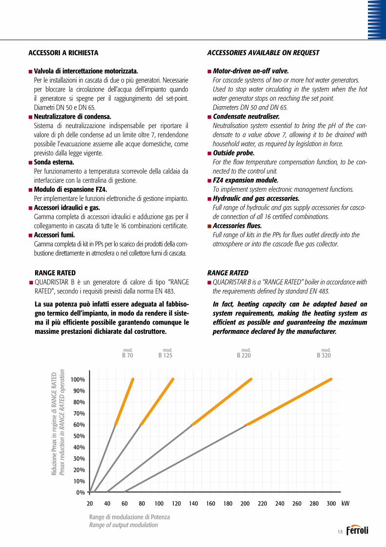
RANGE RATEDnQUADRISTAR B è un generatore di calore di tipo “RANGE
RATED”, secondo i requisiti previsti dalla norma EN 483.
La sua potenza può infatti essere adeguata al fabbiso-gno termico dell’impianto, in modo da rendere il siste-ma il più efficiente possibile garantendo comunque le massime prestazioni dichiarate dal costruttore.
RANGE RATED nQUADRISTAR B is a “RANGE RATED” boiler in accordance with
the requirements defined by standard EN 483.
In fact, heating capacity can be adapted based on system requirements, making the heating system as efficient as possible and guaranteeing the maximum performance declared by the manufacturer.
mod.B 70
mod.B 125
mod.B 220
mod.B 320
0%
10%
20%
30%
40%
50%
80%
60%
90%
70%
100%
140 26080 2004020 160 280100 22060 180 300 kW120 240
Ridu
zione
Pm
ax in
regi
me
di R
ANGE
RAT
EDPm
ax re
duct
ion
in R
ANGE
RAT
ED o
pera
tion
Range di modulazione di PotenzaRange of output modulation
13

14
QUADRISTAR B MODULARE
Ogni particolare è stato pensato per facilitare le installazioni in cascata. Elenchiamo di seguito i punti più importanti.
n Gli attacchi idraulici sono stati posizionati alle stesse altezze in modo da favorirne il collegamento ai collettori di mandata e ritorno dell’impianto.
n La doppia uscita fumi sui lati destro e sinistro del generatore e la serranda anti riflusso posizionata direttamente sul ventilatore, facili-tano il dimensionamento e la realizzazione del collettore fumi.
nLa gamma Quadristar B è abbinata ad una serie completa di accessori per più combinazioni in batteria da due o tre genera-tori, fino al raggiungimento di una potenza massima di 960 kW.
Every part has been designed to simplify cascade instal-lations. The main points are as follows.
n The water fittings have been positioned at the same heights so as to simplify connection to the system outlet and return manifolds.
n The double flue gas outlet on the right and left sides of the boiler, and the non-return damper positioned directly on the fan simplify sizing and development of the flue gas manifold.
n The Quadristar B range features a complete series of acces-sories for multiple combinations in groups of two or three boilers, up to a maximum output of 960 kW.
Generatore termico equivalente, certificato INAIL, a condensa-zione, predisposto per 16 tipologie di installazioni modulari con due o tre generatori.Gamma composta da sedici modelli con potenze termiche max da 140 kW a 960 kW rispettivamente.
Multi modules condensing generator, set for 16 types of modu-lar installations with two or three boilers.Range consisting of sixteen models with max heat outputs from 140 kW to 960 kW respectively.
Gruppo termico in acciaio a condensazioneCondensing hot water generator
HHHH

15
nOgni configurazione completa degli accessori fumi, idraulici e gas è stata sottoposta all’approvazione dell’INAIL e quindi certificata come “Generatore unico”.
nL’elettronica montata di serie è stata progettata per poter gestire autonomamente le dinamiche di più generatori in cascata, con la logica del MASTER-SLAVE, fino ad un massimo di 6.
nIl sistema aria/gas è stato progettato per poter dimensionare il collet-tore fumi della batteria in pressione e di conseguenza utilizzare dei collettori con diametri ridotti rispetto ad un sistema in pressione.
nTramite la parametrizzazione della scheda del MASTER di casca-ta, è possibile impostare la sequenza di accensione dei vari moduli e la rotazione della sequenza di accensione in modo da ripartire il numero di ore di funzionamento uniformemente.
n The electronic controller fitted as standard has been designed to independently manage the operation of multiple heat generators in a cascade, with MASTER-SLAVE logic, up to a maximum of 6 appliances.
n The air/gas system has been designed to allow the group flue gas manifold to be sized for operation under pressure and consequently allow smaller manifolds.
n The parameters available on the cascade MASTER board can be set so as to select the activation sequence of the various modules and rotation of the activation sequence, so as to uniformly divide the number of operating hours.
CONFIGURAZIONI INSTALLAZIONE A CASCATA CONFIGURATION OF CASCADE INSTALLATION
Nota: per altre configurazioni non indicate in tabella l’Azienda non fornisce gli accessoriNote: For other configurations not shown in the table, the Company does not provide accessories
QUADRISTAR B MODULARE
Portata termicaHeat input
Potenza termicaHeat output
Modulazione batteriaBattery modulation
Nr. ModuliModules Nr.
Combinazione modelliModels combination
max 80/60°C 50/30°C Pmin/Pmax 50/30°C 1 2 3kW kW kW
131,0 128,8 139,8 15,0/139,8 2 70 70 -
181,5 178,4 194,9 15,0/194,9 2 70 125 -
232,0 228,0 250,0 24,8/250,0 2 125 125 -
247,0 242,8 264,8 15,0/264,8 3 70 70 125
297,5 292,4 319,9 15,0/319,9 3 70 125 125
323,0 318,0 345,0 24,8/345,0 2 125 220 -
348,0 342,0 375,0 24,8/375,0 3 125 125 125
414,0 408,0 440,0 44,2/440,0 2 220 220 -
439 432,0 470,0 24,8/470,0 3 125 125 220
506,0 498,5 540,0 44,2//540,0 2 220 320 -
530, 522,0 565,0 24,8/565,0 3 125 220 220
598,0 589,0 640,0 66,8/640,0 2 320 320 -
621,0 612,0 660,0 44,2/660,0 3 320 220 220
713,0 702,5 760,0 44,2/760,0 3 220 220 320
818,0 793,0 860,0 44,2/860,0 3 220 320 320
897,0 883,5 960,0 66,8/960,0 3 320 320 320

16
QUADRISTAR B MODULARE
DESCRIZIONE ACCESSORI BATTERIAC Curva a 90° M-F in polipropilene completa di guarnizione - E Collettore fumo in poipropilene completo di guarnizioni - P Partenza cieca collettore fumi completo di sifone scarico con-densa - R Riduzione da attacco collettore a tratto verticale del percorso fumi completo di guarnizione - T Tubo fumo per tratto verticale di collegamento dall’uscita fumi caldaia al collettore, completo di guarnizione - V Valvola di intercettazione a farfalla motorizzata.
BATTERY ACCESSORIES DESCRIPTION C Polypropylene 90° MF bend with gasket - E Polypropylene exhaust manifold with gaskets - P Vertical connection with condensate drain trap - R Reduction from collective flues manifold to boiler’s stach with gaskets - T Boiler’s vertical flues piping, with gasket - V Motorized water circuit on/off solenoid valve.
CONFIGURAZIONE ACCESSORI COLLETTORE FUMI
EXHAUST MANIFOLDS ACCESSORIES MATCHING
COLLETTORE FUMI USCITA BASSAEXHAUST MANIFOLDS LOW EXIT
COLLETTORE FUMI USCITA MEDIAEXHAUST MANIFOLDS MEDIUM EXIT
COLLETTORE FUMI USCITA ALTAEXHAUST MANIFOLDS HIGH EXIT
HHHH

17
DESCRIZIONE ACCESSORI BATTERIAA Adattatore attacchi valvola intercettazione motorizzata - B Adattatore attacchi caldaia/collettore - F Kit flange collettore composto da una flangia cieca e una forata complete di guarnizioni, viti e dadi - G Collettore gas completo di rubinetto a sfera, flessibile, guarnizioni, viti e dadi - I Collettore idraulico completo di guarnizioni, viti e dadi - S tronchetto INAIL con pozzetti per apparecchiature di sicurezza (non fornite) completo di guarnizioni, viti e dadi - V Valvola di intercettazione a farfalla motorizzata.
BATTERY ACCESSORIES DESCRIPTION A Motorized water circuit on/off solenoid valve connection adapter - B Boiler/manifold connection adapter - F Blind flange and drilled flange kit with gaskets, screws and nuts - G Gas manifold with ball valve, hose, gaskets, nuts and bolts - I Hydraulic manifold with gaskets, screws and nuts - V Motorized water circuit on/off solenoid valve.
COLLETTORI IDRAULICI E GAS WATER AND GAS MANIFOLDS
G
I
I
I
B
A
V
A
V
A
A

18
TP3 COND HHHH
Generatore termico a condensazione a tre giri di fumoCondensing generator with three flue passes
Generatore termico a condensazione a sviluppo orizzontale per la combustione pressurizzata a tre giri di fumo a fiamma passante, con un’efficienza energetica certificata a quattro stelle secondo la direttiva EN 15502-1. Predisposto per funzionare in abbinamento ad un bruciatore ad aria soffiata a combustibile gassoso. La geometria della camera di combustione, ed il gene-roso dimensionamento, garantiscono un basso carico termico e la possibilità di essere abbinate a bruciatori dotati di tecnologie per la combustione a bassi tenori di inquinanti.Gamma composta da 7 modelli con potenze nominali da 820 a 2.600 kW. nCorpo caldaia, rivestito esternamente con una protezione
in lamierino di acciaio verniciato con polveri epossidiche e costituito da:tubo per il passaggio del secondo giro fumi con ripresa dal fondo del focolare, dimensionato per ottimizzare i parame-tri di combustione;fascio tubiero per il terzo passaggio fumi posta nella parte inferiore del generatore e dotata di turbolatori in acciaio per l’innalzamento dello scambio convettivo.
Horizontal condensing generator for pressurised combustion with three flue gas passes and four-star certified energy effi-ciency in accordance with directive EN 15502-1.Ready for operation in combination with a jet burner on gas fuel. The arrangement and generous sizing of the combustion chamber guarantee a low heating load and the possibility to be combined with burners featuring technology for the combustion with low polluting emissions.Range consisting of 7 models with rated outputs from 820 to 2,600 kW.nBoiler body lined on the outside with steel plate protection
painted with epoxy powder coat, and consisting of:pipe for the second flue pass with intake from the bottom of the furnace, sized to optimise combustion parameters;tube bundle for the third flue gas pass located at the lower part of the hot water generator, fitted with steel turbula-tors to increase convective heat exchange.
RENDIMENTO FINO A 107%EFFICIENCY UP TO 107%
LOW NOx CLASSE 5 SECONDO EN 15502-1LOW NOx CLASS 5 ACCORDING TO EN 15502-1

19
nEfficienza energetica superiore al 107%.nPressione massima di esercizio 5 bar.nTemperatura massima di progetto 100°C.nCamera di combustione a fondo bagnato flottante con
carico termico volumetrico inferiore a 1,1 MW/m3 per garantire valori di emissioni in atmosfera di ossidi azoto inferiori a 80 mg kW/h, in abbinamento ad opportuni bruciatori.
nAttacchi flangiati completi di controflange.nPortellone anteriore con apertura reversibile da ambo i lati
ed innovativo sistema di chiusura e regolazione micrometrica sul corpo caldaia. Isolamento termico con materiale ad elevato potere coibentante e ridotta inerzia termica e protezione in materiale refrattario sul lato focolare e sul lato giro fumi.
nIsolamento termico esteso a tutte le parti della caldaia e ottenuto con uno strato di lana minerale dello spessore di 80 mm che avvolge l’intero fasciame.
CERTIFICAZIONIMarcatura CE secondo le Direttive Apparecchi a Gas (2009/142 CEE)Rendimenti (92/42 CEE)Bassa Tensione (2014/35/EU)Compatibilità Elettromagnetica (2014/30/EU)
nEnergy efficiency exceeding 107%.nMaximum operating pressure 5 bars.nMaximum design temperature 100°C.nFloating combustion chamber with cooled end plate,
volumetric heating load less than 1.1 MW/m3 to ensure atmo-spheric nitrogen oxide emissions less than 80 mg kW/h, in combination with suitable burners.
nFlanged fittings complete with counterflanges.nFront door with reversible opening from both sides and inno-
vative closing system with micrometric adjustment on the boiler body. Heat insulation using with material with excellent insulting properties and reduced thermal inertia, protected by refractory material on the furnace side and on the flue gas pass side.
nHeat insulation extended to all parts of the boiler using an 80 mm thick layer of mineral wool on all the plating.
CERTIFICATIONCE mark in accordance with the following directives Gas Appliances (2009/142 EEC)Efficiency (92/42 EEC)Low Voltage (2014/35/EU)Electromagnetic Compatibility (2014/30/EU)
Terzo passaggio fumi con turbolatori
Third flue gas pass with turbulators
Secondo passaggio fumi con ripresa posteriore
Second flue gas pass with intake at rear
Isolamento preformato su lato focolare e su lato inversione fumi
Preformed insulation on furnace side and on flue gas reversal side
Portellone con apertura reversibile DX e SX fornito con piastra portabruciatore cieca
Door with reversible opening, R and L, supplied with blind burner anchor plate
Mandata impianto
Central heating flow outlet
Ritorno bassa temperatura
Low temperature return
Focolare a basso carico termicocompletamente bagnato
Completely cooled furnace with low heating load
Sistema chiusura e regolazione portellone
Door closing and adjustment system
Ritorno alta temperatura
High temperature return
Attacco sicurezza
Safety connection

20
TP3 COND HHHHDIMENSIONIDIMENSIONS
Legenda1 Caldaia2 Porta3 Camera fumo4 Quadro elettrico
Key1 Boiler2 Door3 Smokebox4 Electrical panel
TP3 COND 820÷2600Disegno / Drawing Nr. 3937089/1Generatore d'acqua calda
Hot water generator rev. 23-04-2015
FERROLI S.p.A. si riserva a termini di legge la propietà del presente disegno con divieto di riprodurlo o comunicarlo senza sua autorizzazione. L'Azienda precisa che le caratteristiche estetiche e/o dimensionali, i dati tecnici e gli accessori possono essere soggetti a variazione.
FERROLI S.p.A. reserved accordingly current laws this drawing's property with its reproducing and development prohibition without his authorization. The Company stresses that appearance and/or size, technical specifications and accessories may be subject to varation.
TP3 COND
T1
T4T5T6
ABC
DN150
DN1001 1/2"400Ø mm
T2 DN150mandata - flow
ritorno bassa temp. - Low temp. return
sicurezze - safety
uscita fumo - flue outletscarico caldaia / condense - drain
ATTA
CCHI
-FIT
TING
DEDIMENSIONI - DIMENSIONS
1240239421161180206
Pressione max esercizio *Pressione provaTemperatura progetto
Max working pressure *Hydraulic test pressureDesign temperature
5 bar7,5 bar110 °C
1250
744
DN150
DN1001 1/2"400
DN150
1240274421161180206
1450
864
DN150
DN1001 1/2"450
DN150
1360274423461300206
2200
1310
DN200
DN1251 1/2"500
DN200
1450334425111390206
%
dm 3
KWPotenza utile - Heat output
Capacità totale caldaia - Boiler total capacity
Rendimento - Heat input 30%
Pressione max esercizio - Max working pressure barkgPeso a secco - Dry weight standard
KW max min
KWPotenza focolare - Heat inputKW
max min80
°C / 6
0°C
max min
KWKW
max min
%Rendimento - Efficiency
%80/6050/30 max
Classe NOx - NOx class
107,3 107,0 106,9 107,1108 108 108 1085 5 5 5
1785 2047 2480 3670
5 5 5 52500 2800 3350 4600
1145 1330 2015
T3 DN80ritorno alta temp. - High temp. return DN80 DN80 DN100
97,6 98,1 98,2 98,0
1700
1014
DN200
DN1251 1/2"500
DN200
1450294425111390206
107,0108
53020
54100
1560
DN100
98,0
50°C
/ 30°
C Potenza utile - Heat output
Potenza focolare - Heat input KWKW
Legenda 1 Caldaia 2 Porta 3 Camera Fumo 4 Quadro elettrico
Key 1 Boiler 2 Door 3 Smokebox 4 Electrical panel
Perdite carico lato acqua - Loss pressure water side t 15 °C m barPerdite carico lato fumi - Pressure drop flue gas side m barPortata fumi * - Flue gas flow-rate * kg/h
40 55 45 65706,2 7,4 7,4 7,87,2- - - --
attacco bruciatore - burner attac. fittinglg. min/max boccaglio - lg. min/max draugt tube burner
T7Ø mm 350 350 350 350350
340/410 340/410 340/410 340/470 350/480
F 262 262 266 262262G 860 860 960 10101010H 1565 1565 1745 18801880I 2926 3275 3275 38663466M 2185 2185 2415 25802580
* Combustibile gas: CO² = 10%* Gas fuel: CO² = 10%
2600
15482381
812,51168350
942,51355406,5
14302056617
1250 1450 220011051589477
170016902430729
2600
1168 1355 20561589 2430350 406,5 617477 729
DN125
DN801 1/2"350
DN125
1180224420061120206
1000
595
107,1108
51565
52150
916
DN65
98,0
466,4-
270320/390
262830148027122075
650935280
1000
935280
DN125
DN80 1 1/2"
350
DN125
1180209420061120206
820
489
106,81085
1450
52050
752
DN65
97,5
356-
270320/390
262830
148025622075
533767230
820
767230
1
2
3
4
T3 T1
T6
T5
T4T2T2-T3-T4-T1
D
C
A
H
G
M
F B EI
T7
TP3 COND 820 1000 1250 1450 1700 2200 2600
DIMENSIONI A mm 1180 1180 1240 1240 1360 1450 1450 DIMENSIONS B mm 2094 2244 2394 2744 2744 2944 3344 C mm 2006 2006 2116 2116 2346 2511 2511 D mm 1120 1120 1180 1180 1300 1390 1390 E mm 206 206 206 206 206 206 206 F mm 262 262 262 262 262 262 262 G mm 830 830 860 860 960 1010 1010 H mm 1480 1480 1565 1565 1745 1880 1880 I mm 2562 2712 2926 3275 3275 3466 3866 M mm 2075 2075 2185 2185 2415 2580 2580 Mandata / Flow T1 DN125 DN125 DN150 DN150 DN150 DN200 DN200 Ritorno bassa temp. / Low temp. return T2 DN125 DN125 DN150 DN150 DN150 DN200 DN200 Ritorno alta temp. / High temp. return T3 DN65 DN65 DN80 DN80 DN80 DN100 DN100 Sicurezze / Safety T4 DN80 DN80 DN100 DN100 DN100 DN125 DN125 Scarico caldaia-condense / Drain T5 1” 1/2 1” 1/2 1” 1/2 1” 1/2 1” 1/2 1” 1/2 1” 1/2 Uscita fumo / Flue outlet T6 Ø mm 350 350 400 400 450 500 500 Attacco bruciatore / Burner attac. fitting T7 Ø mm 270 270 350 350 350 350 350 Lg. min/max boccaglio
T7 320/390 320/390 340/410 340/410 340/410 340/470 350/480 Lg. min/max draugt tube burner Peso a secco / Dry weight standard kg 2050 2150 2500 2800 3350 4100 4600
DATI TECNICI / TECHNICAL DATA TP3 COND 820 1000 1250 1450 1700 2200 2600
Potenza utile 80/60°C min kW 489 595 744 864 1014 1310 1548 Heat output 80/60°C max kW 752 916 1145 1330 1560 2015 2381 Potenza focolare 80/60°C min kW 230 280 350 406,5 477 617 729 Heat input 80/60°C max kW 767 935 1168 1355 1589 2056 2430 Potenza utile 50/30°C min kW 533 650 812,5 942,5 1105 1430 1690 Heat output 50/30°C max kW 820 1000 1250 1450 1700 2200 2600 Potenza focolare 50/30°C min kW 230 280 350 406,5 477 617 729 Heat input 50/30°C max kW 767 935 1168 1355 1589 2056 2430 Rendimento / Efficiency
80/60°C % 97,5 98,0 97,6 98,1 98,2 98,0 98,0 50/30°C % 106,8 107,1 107,3 107,0 106,9 107,0 107,1 Rendimento / Heat input 30% max % 108 108 108 108 108 108 108 Classe NOx / NOx class 5 5 5 5 5 5 5 Capacità totale caldaia / Total boiler capacity dm3 1450 1565 1785 2047 2480 3020 3670 Perdite di carico lato acqua
∆t 15°C mbar 35 46 40 55 45 70 65 Loss pressure water side Perdite carico lato fumi / Press. drop flue gas side mbar 6 6,4 6,2 7,4 7,4 7,2 7,8 Pressione max esercizio / Max working pressure bar 5 5 5 5 5 5 5
* Combustibile gas: CO2 = 10%* Gas fuel: CO2 = 10%

21
ACCESSORI A RICHIESTA
nQuadro comandi THERMO EBM.Di tipo elettronico per la gestione del generatore (anche con bruciatori modulanti), con controllo a microprocessore; con unità logica alloggiata nella scocca e interfaccia utente, con display LCD, fronte quadro.
nSonda esterna.Per funzionamento a temperatura scorrevole della caldaia, da interfacciare con il quadro comandi THERMO EBM.
nSonda cascata/mandata/bollitore.Da interfacciare con il quadro comandi THERMO EBM dipen-dentemente dalle esigenze.
nQuadro comandi industriale.
Per particolari esigenze in merito ad accuratezza di regolazione oppure per installazioni in ambito sicuro.
nQuadro comandi con PLC.Per esigenze specifiche di comunicazione con BMS o sistemi di supervisione.
nBruciatore a gas.nPiastra porta bruciatore forata secondo le indicazioni del
cliente.nNeutralizzatore di condensa.
Sistema di neutralizzazione indispensabile per riportare il valore di ph delle condense ad un limite oltre 7, rendendone possibile l’evacuazione assieme alle acque domestiche, come previsto dalla legge vigente.
ACCESSORIES AVAILABLE ON REQUEST
nTHERMO EBM control panel.Electronic for managing the hot water generator (including with modulating burners), with microprocessor control; logical control unit housed inside the casing and user interface with LCD on the front panel.
nOutside probe.For boiler temperature compensation operation, to be con-nected to the THERMO EBM control panel.
nCascade/outlet/storage cylinder probe.Connected to the THERMO EBM control panel based on requirements.
nIndustrial control panel.
For special needs regarding precision control or installation in safe environments.
nControl panel with PLC.For specific communication needs to BMS or supervision systems.
nGas burner.nPerforated burner plate based on customer specifi-cations.nCondensate neutraliser.
Neutralisation system essential to bring the pH of the con-densate to a value above 7, allowing it to be drained with household water, as required by legislation in force.

22
Accessori / AccessoriesNEUTRALIZZATORE DI CONDENSAPer generatori singoli o in cascata fino alla potenza massima totale di 320 kW. Portata massima di condensa di 70 l/h.Composto da:n 1 contenitore 410x310 mm, h 220 mm in polipropilene alimentare.n 1 coperchio in ABS antiurto sagomato.n 2 passaparete da 1” con filtro e portagomma con ghiera (entrata/uscita).n 2 tubi di gomma Ø 25x32 mm da 2 m cad.n 1 sacco granulato da 25 kg.n 1 cartone imballo di forte spessore con manici incavati contenente neutralizzatore,
sacco granulato e accessori.
CONDENSATE NEUTRALISERFor individual or cascaded boilers up to a maximum total output of 320 kW.Maximum condensate flow-rate 70 l/h.Composition:n 1 x 410x310 mm container, h 220 mm, made from food safe polypropylene.n 1 specially-shaped shockproof ABS cover.n 2 x 1” bulkhead connectors with filter and barbed connector with ring nut (inlet/
outlet).n 2 x 25x32 mm dia. rubber hoses, each 2 m longn 1 x 25 kg sack of granules.n 1 sturdy cardboard box with cut out hand grips containing neutraliser, sack of granules
and accessories.
NEUTRALIZZATORE DI CONDENSA CON POMPA DI RILANCIOPer generatori singoli o in cascata fino alla potenza massima totale di 320 kW.Portata massima di condensa di 150 l/h.Composto da:n 1 contenitore 400x300 mm, h 220 mm in polipropilene alimentare.n 1 coperchio in ABS antiurto sagomato.n 1 passaparete da 1” con filtro e portagomma con ghiera (entrata/uscita).n 1 tubo di gomma Ø 25x32 mm da 2 m.n 1 tubo di gomma trasparente 10x14 mm da 5 m.n 1 gruppo di rilancio condensa trattata composto da pompa centrifuga inserita in appo-
sito serbatoio di 0,5 litri, completo di valvola di non ritorno, galleggiante attivazione/disattivazione, galleggiante allarme malfunzionamento, protezione termica con riarmo automatico. Portata a 3 metri 2,5 l/min., grado di protezione IP X4.
n 1 sacco granulato da 25 kg.n 1 cartone imballo di forte spessore con manici incavati contenente neutralizzatore,
sacco granulato e accessori.
CONDENSATE NEUTRALISER WITH BOOSTER PUMPFor individual or cascaded boilers up to a maximum total output of 320 kW.Maximum condensate flow-rate 150 l/h.Composition:n 1 x 400x300 mm container, h 220 mm, made from food safe polypropylene.n 1 specially-shaped shockproof ABS cover.n 1 x 1” bulkhead connector with filter and barbed connector with ring nut (inlet/
outlet).n 1 x 25x32 mm dia. rubber hose, 2 m long.n 1 x 10x14 mm transparent rubber hose, 5 m long.n 1 condensate booster pump unit consisting of a centrifugal pump in a special 0.5
litre tank, complete with non-return valve, on/off float, malfunction alarm float, circuit breaker with automatic reset. Flow-rate at 3 metres 2.5 l/min., index of protection IP X4.
n 1 x 25 kg sack of granules.n 1 sturdy cardboard box with cut out hand grips containing neutraliser, sack of
granules and accessories.

23
NEUTRALIZZATORE DI CONDENSAPer generatori singoli o in cascata fino alla potenza massima totale di 1500 kW. Portata massima di condensa di 300 l/h. Composto da:n1 contenitore 670x470 mm, h 180 mm sagomato, con 4 divisorie interne, in ABS antiurto n1 coperchio in ABS antiurto sagomato n2 passaparete da 1” con filtro e portagomma con ghiera (entrata/uscita) n1 passaparete da 1” con gomito e porta-gomma con ghiera (troppo pieno) n2 tubi di gomma Ø 25x32 mm da 2 m cad. n1 sacco granulato da 25 kg n1 cartone imballo di forte spessore con manici incavati contenente neutralizzatore, sacco granulato e accessori.
CONDENSATE NEUTRALISERFor individual or cascaded boilers up to a maximum total output of 1500 kW.Maximum condensate flow-rate 300 l/h. Composition:n 1 specially-shaped 670x470 mm container, h 180 mm, with 4 internal partitions, made from shockproof ABS n 1 specially-shaped shockproof ABS cover n 2 x 1” bulkhead connectors with filter and barbed connector with ring nut (inlet/outlet) n 1 x 1” bulkhead connector with elbow and barbed connector with ring nut (overflow) n 2 x 25x32 mm dia. rubber hoses, each 2 m long n 1 x 25 kg sack of granules n 1 sturdy cardboard box with cut out hand grips containing neutraliser, sack of granules and accessories.
NEUTRALIZZATORE DI CONDENSA CON POMPA DI RILANCIOPer generatori singoli o in cascata fino alla potenza massima totale di 1500 kW.Portata massima di condensa di 550 l/h. Composto da:n1 contenitore 670x470 mm, h 280 mm in polipropilene alimentare n1 coperchio in ABS antiurto sagomato n1 passaparete da 1” con filtro e portagomma con ghiera (entrata/uscita) n1 passaparete da 1” con gomito e portagomma con ghiera (troppo pieno) n1 tubo di gomma Ø 25x32 mm da 2 m n1 tubo di gomma trasparente 10x14 mm da 5 m n 1 gruppo di rilancio condensa trattata composto da pompa centrifuga, galleggiante attivazione/disattivazione, galleggiante allarme malfunzio-namento, protezione termica con riarmo automatico. Portata a 3 metri 9,2 l/min., grado di protezione IP X4 n1 sacco granulato da 25 kg n1 cartone imballo di forte spessore con manici incavati contenente neutralizzatore, sacco granulato e accessori.
CONDENSATE NEUTRALISER WITH BOOSTER PUMPFor individual or cascaded boilers up to a maximum total output of 1500 kW.Maximum condensate flow-rate 550 l/h. Composition:n1 x 670x470 mm container, h 280 mm, made from food safe polypropylene n
1 specially-shaped shockproof ABS cover n 1 x 1” bulkhead connector with filter and barbed connector with ring nut (inlet/outlet) n 1 x 1” bulkhead connector with elbow and barbed connector with ring nut (overflow) n 1 x 25x32 mm dia. rubber hose, 2 m long n 1 x 10x14 mm transparent rubber hose, 5 m long n 1 condensate booster pump unit consisting of a centrifugal pump, on/off float, malfunction alarm float, circuit breaker with automatic reset. Flow-rate at 3 metres 9.2 l/min., index of protection IP X4 n 1 x 25 kg sack of granules n 1 sturdy cardboard box with cut out hand grips containing neutraliser, sack of granules and accessories.
VALVOLA INTERCETTAZIONE GENERATOREValvola a farfalla motorizzata, alimentata 230V/50Hz, da utilizzare nel caso di installazione di più generatori in batteria. Comandata direttamente dall’elettronica della caldaia, impe-disce la circolazione nei generator spenti.Disponibile in due modelli, rispettivamente del diametro DN 50 e DN 65.
BOILER ON-OFF VALVEMotor-driven throttle valve, powered at 230V/50Hz, to be used when a series of boi-lers are installed. Controlled directly by the boiler’s electronics, prevents circulation when the boiler is off.Two models available, diameter DN 50 and DN 65 respectively.

24
Caldaia per acqua calda a tre giri di fumo di cui due in camera di combustioneHot water boiler with three flue passes, two in furnace
NGT/RSW (export) HH92÷1890
Generatore termico a combustione pressurizzata, predisposto per funzionare in abbinamento ad un bruciatore ad aria sof-fiata a combustibile liquido o gassoso. Camera di combustione completamente bagnata e dimensionata in modo tale da assi-curare bassi carichi termici. Focolare ad inversione di fiamma a basso carico termico. Gamma composta da 18 modelli con potenze nominali da 92 a 1.890 kW.nCorpo caldaia interamente in acciaio, completamente rivesti-
to con un materassino di 80 mm in lana di vetro ad alta densità, ricoperto a sua volta da un resistente strato di materiale antistrappo.
nPressione massima di esercizio 6 bar, pressioni superiori a richiesta.nCamera di combustione pressurizzata, completamente
bagnata e protetta da un sistema di ripartizione omogenea dell’ac-qua fredda di ritorno dall’impianto, al fine di evitare dannosi salti termici. L’asse del bruciatore non coincide con quello della camera di combustione ma è spostato verso il basso. Ciò per favorire l’inversione di fiamma, ridurre le perdite di carico sul lato fumi e di conseguenza ampliare il campo di utilizzo del generatore.
Hot water generator with pressurised combustion, ready for operation in combination with a jet burner on liquid or gas fuel. Completely cooled combustion chamber, sized to ensure low heating loads. Furnace with flame reversal and low heating load. Range consisting of 18 models with rated outputs from 92 to 1,890 kW.
nBoiler body made entirely from steel, completely lined withan 80 mm layer of high density glass wool, in turn covered by a strong layer of tearproof material.
nMaximum operating pressure 6 bars, higher pressures on request.nPressurised combustion chamber, completely cooled and
protected by a system ensuring uniform division of the cold system return water, to avoid dangerous temperature diffe-rences. The burner is not aligned with the combustion cham-ber but rather has been moved downwards. This assists flame reversal, reduces the flue gas pressure drop and consequently extends the hot water generator’s range of application.
DISPONIBILE ANCHE IN VERSIONE SCOMPOSTA DA ASSEMBLARE IN CENTRALE
ALSO AVAILABLE IN THE DISMANTLED VERSION TO BE ASSEMBLED IN THE HEATING PLANT

25
nFascio tubiero disposto sopra il focolare in modo da garanti-re il passaggio dei fumi in una sezione calda del generatore e di conseguenza ridurre il rischio di condense.
nTurbolatori di nuova progettazione in grado di aumentare loscambio termico, senza penalizzare le perdite di carico in caldaia.
nPortellone anteriore con apertura reversibile (destra e sini-stra) ed innovativo sistema di chiusura e regolazione microme-trica sulla piastra frontale del generatore. Fino al modello 940 il portellone è isolato con doppio rivestimento composto da uno strato in fibra ed uno in carbowool mentre per i modelli di potenza superiore viene utilizzato un doppio strato di cemento refrattario e isolante.
nAttacchi mandata e ritorno impianto filettati fino al model- lo 399 e flangiati PN10 per i restanti.nFornita in 3 parti: corpo in acciaio, mantellatura e satellite comandi (satellite da ordinare a parte).
CERTIFICAZIONIMarcatura CE secondo le Direttive Apparecchi a Gas (2009/142 CEE)Rendimenti (92/42 CEE)Bassa Tensione (2014/35/EU)Compatibilità Elettromagnetica (2014/30/EU)
nTube bundle placed above the furnace so as to guaranteethe flue gas passes through a hot section of the hot water generator and consequently reduce the possibility of condensate forming.
nTurbulators featuring a new design able to increase heat exchange, without affecting pressure drop in the boiler.nFront door with reversible opening(right and left) and inno-
vative closing system with micrometric adjustment on the hot water generator front plate. Up to model 940 the door is insulated with double lining, made up of one layer of fibre and one layer of Carbowool, while higher output models use a double layer of refractory concrete and insulation.
nThreaded central heating flow outlet and return inletconnections up to model 399 and flanged PN10 for the remaining models.
nSupplied in 3 parts: steel body, casing and satellite controls (satellite to be ordered separately).
CERTIFICATIONCE mark in accordance with the following directives Gas Appliances (2009/142 EEC)Efficiency (92/42 EEC)Low Voltage (2014/35/EU)Electromagnetic Compatibility (2014/30/EU)
Doppio strato isolantein fibra e carbowool
Double fibre and Carbowool insulating layer
Corpo caldaia interamente rivestito con un materassino in lana minerale
Boiler body completely lined with rock wool insulation
Ritorno impianto
Central heating return inlet
Mandata impianto
Central heating flow outlet Attacco sicurezza
Safety connection
Camera di combustione completamente bagnata
Completely cooled combustion chamber
Portellone con aperturareversibile dx e sx
Door with reversible
opening, R and L
Sistema di chiusurae regolazione portellone
Door closing and adjustment system

26
NGT/RSW (export) HH92÷1890DIMENSIONIDIMENSIONS
* Combustibile gasolio: CO2 = 13% - Combustibile gas: CO2 = 10%* Oil fuel: CO2 = 13% - Gas fuel: CO2 = 10%
NGT/RSW 92 107 152 190 240 300 350 399 525 600 720 820 940 1060 1250 1480 1600 1890
DIMENSIONI A mm 760 760 810 810 810 950 950 950 1060 1060 1260 1260 1260 1450 1450 1530 1530 1530 DIMENSIONS B mm 764 764 1014 1014 1264 1264 1514 1515 1516 1776 1776 1776 2016 2018 2018 2320 2320 2520 C mm 866 856 911 911 911 1031 1031 1031 1181 1181 1331 1331 1331 1511 1511 1661 1661 1661 D mm 165 165 165 165 165 165 165 165 165 165 165 165 165 165 165 165 165 165 E mm 130 130 130 130 130 150 150 150 170 170 170 170 170 190 190 190 190 190 F mm 152 152 152 152 152 152 152 152 152 152 212 212 212 212 212 212 212 212 G mm 515 515 545 545 545 630 630 630 725 725 815 815 815 900 900 1013 1013 1013 H mm 395 395 420 420 420 495 495 485 570 570 615 615 615 670 670 743 743 743 I mm 1046 1046 1296 1296 1516 1546 1816 1817 1838 2098 2158 2158 2398 2420 2420 2722 2722 2722 M mm 925 925 980 980 980 1100 1100 1100 1250 1250 1400 1400 1400 1580 1580 1730 1730 1730 Mandata / Flow T1 2” 2” 2” 1/2 2” 1/2 2” 1/2 2” 1/2 2” 1/2 2” 1/2 DN 80 DN 80 DN100 DN100 DN100 DN125 DN125 DN150 DN150 DN150 Ritorno / Return T2 2” 2” 2” 1/2 2” 1/2 2” 1/2 2” 1/2 2” 1/2 2” 1/2 DN 80 DN 80 DN100 DN100 DN100 DN125 DN125 DN150 DN150 DN150 Sicurezze / Safety T3 1” 1/4 1” 1/4 1” 1/2 1” 1/2 1” 1/2 1” 1/2 1” 1/2 1” 1/2 2” 2” 2” 1/2 2” 1/2 2” 1/2 3” 3” DN100 DN100 DN100 Scarico / Drain T4 3/4” 3/4” 3/4” 3/4” 3/4” 3/4” 3/4” 3/4” 3/4” 3/4” 3/4” 3/4” 3/4” 3/4” 3/4” 1” 1/2 1” 1/2 1” 1/2 Uscita fumo / Flue outlet T5 Ø mm 200 200 220 220 220 220 220 220 250 250 350 350 350 400 400 450 450 450 Attacco bruciatore / Burner attac. fitting T6 Ø mm 145 145 150 150 150 240 240 240 210 210 270 270 270 270 270 350 350 350 Lg. min/max boccaglio
T6 250/320 250/320 250/320 250/320 250/320 250/320 250/320 250/320 290/360 290/360 320/390 320/390 320/390 320/390 320/390 350/420 350/420 350/420 Lg. min/max draugt tube burner Peso a secco / Dry weight standard 6 bar kg 260 260 350 350 440 480 550 590 860 970 1250 1250 1420 1580 2250 2650 2700 2850
DATI TECNICI / TECHNICAL DATA NGT/RSW 92 107 152 190 240 300 350 399 525 600 720 820 940 1060 1250 1480 1600 1890
Potenza utile min kW 60 70 100 137 160 196 228 260 341 390 468 533 611 689 813 962 1040 1229 Heat output max kW 92 107 152 190 240 300 350 399 525 600 720 820 940 1060 1250 1480 1600 1890 Potenza focolare min kW 64,3 75 107,3 147,4 170,9 209,5 242,5 277,5 364,5 417 502 566 651 731 884 1046 1128 1336 Heat input max kW 99,5 116 165 206 261 326 378 432 567 648 777 881 1011 1140 1359 1608 1736 2054
Capacità totale caldaia / Total boiler capacity dm3 120 120 185 185 235 300 360 365 405 465 735 735 850 1250 1250 1500 1500 1630 Perdite di carico lato acqua
∆t 15°C mbar 4 6 12 7 10 17 23 31 22 28 18 25 25 33 40 55 55 45 Loss pressure water side Perdite carico lato fumi / Press. drop flue gas side mbar 0,5 0,7 1,2 1,2 2,3 3,3 3,5 4,4 4,3 4,8 4,5 5,6 5,4 6 6,5 6,5 6,8 7 Portata fumi* / Flue gas flow-rate* kg/h 150 175 249 312 394 492 571 652 856 979 1179 1329 1523 1720 2050 2426 2620 3099 Pressione max esercizio** / Max working pressure** bar 6 6 6 6 6 6 6 6 6 6 6 6 6 6 6 6 6 6
Legenda1 Caldaia2 Porta3 Camera fumo4 Quadro elettrico
Key1 Boiler2 Door3 Smokebox4 Electrical panel
PREXTHERM NGT 92÷1890Disegno / Drawing Nr. 3936613/0Generatore d'acqua calda
Hot water generator rev. 03/03/2011
Pressione max esercizio ** Pressione prova Temperatura progetto
Max working pressure **Hydraulic test pressureDesign temperature
6 bar7,8 bar100 °C
** Pressione max esercizio a richiesta:** Max working pressure on request: 8 bar / 10 bar
KW
dm
KWPotenza utile - Heat output
Capacità totale caldaia - Boiler total capacity
Potenza focolare - Heat input
9260
64,3
120
10770
75
120
152100
107,3
185
190137
147,4
185
240160
170,9
235
300196
209,5
300
350228
242,5
360
399260
277,5
365
525341
364,5
405
PREXTHERM NGT 600390
417
465
720468
502
735
820533
566
735
940611
651
850
18901229
1336
1630Perdite carico lato acqua - Loss pressure water side t 15 °C 4 6 12 7 10 17 23 31 22 28 18 25 25 45m barPerdite carico lato fumi - Pressure drop flue gas side 0,5 0,7 1,2 1,2 2,3 3,3 3,5 4,4 4,3 4,8 4,5 5,6 5,4 7m barPortata fumi * - Flue gas flow-rate * 150 175 249 312 394 492 571 652 856 979 1179 1329 1523 3099kg/hPressione max esercizio ** - Max working pressure ** 6 6 6 6 6 6 6 6 6 6 6 6 6 6bar
6 bar kg 260 260 350 350 440 480 550 590 860 970 1250 1250 1420 2850Peso a secco - Dry weightT1
T3T4T5
ABC
2" 2" 2-1/2" 2-1/2" 2-1/2" 2-1/2" 2-1/2" 2-1/2" DN 80 DN 80 DN100 DN100 DN100 DN150
1-1/4" 1-1/4" 1-1/2" 1-1/2" 1-1/2" 1-1/2" 1-1/2" 1-1/2" 2" 2" 2-1/2" 2-1/2" 2-1/2" DN1003/4" 3/4" 3/4" 3/4" 3/4" 3/4" 3/4" 3/4" 3/4" 3/4" 3/4" 3/4" 3/4" 1-1/2"200 200 220 220 220 220 220 250 250 350 350 350 450Ø mm 220
T2mandata - flowritorno - return
sicurezze - safety
uscita fumo - flue outletscarico - drain
attacco bruciatore - burner attac. fittinglg. min/max boccaglio - lg. min/max draugt tube burner
T6Ø mmAT
TACC
HI -
FITTIN
G
145 145 150 150 150 240 240 210 210 270 270 270 350240250/320 250/320 250/320 250/320 250/320 250/320 250/320 290/360 290/360 320/390 320/390 320/390 350/420250/320
DE
DIMENSIONI - DIMENSIONS
760 760 810 810 810 950 950 1060 1060 1260 1260 1260 1530950764 764 1014 1014 1264 1264 1515 1516 1776 1776 1776 2016 25201514866 856 911 911 911 1031 1031 1181 1181 1331 1331 1331 16611031165 165 165 165 165 165 165 165 165 165 165 165 165165130 130 130 130 130 150 150 170 170 170 170 170 190150
Legenda 1 Caldaia 2 Porta 3 Camera Fumo 4 Quadro elettrico
Key 1 Boiler 2 Door 3 Smokebox 4 Electrical panel
* Combustibile gasolio: CO² = 13% - Combustibile gas: CO² = 10%* Oil fuel: CO² = 13% - Gas fuel: CO² = 10%
standard
1060689
731
1250336
17206
1580DN125
3"3/4"400270
320/390145020181511165190
1250813
884
1250406,5
20506
2250DN125
3"3/4"400270
320/390145020181511165190
1480962
1046
1500556,5
24266
2650DN150
DN1001-1/2"450350
350/420153023201661165190
16001040
1128
1500556,8
26206
2700DN150
DN1001-1/2"450350
350/420153023201661165190
F 152 152 152 152 152 152 152 152 152 212 212 212 212152 212 212 212 212G 515 515 545 545 545 630 630 725 725 815 815 815 1013630 900 900 1013 1013H 395 395 420 420 420 495 485 570 570 615 615 615 743495 670 670 743 743I 1046 1046 1296 1296 1516 1546 1817 1838 2098 2158 2158 2398 27221816 2420 2420 2722 2722M 925 925 980 980 980 1100 1100 1250 1250 1400 1400 1400 17301100 1580 1580 1730 1730
minmaxminmax
92 107 152 190 240 300 350 399 525 600 700 820 940 18901060 1250 1480 1600
99,5 116 165 206 261 326 378 432 567 648 777 881 1011 20541140 1359 1608 1736
2" 2" 2-1/2" 2-1/2" 2-1/2" 2-1/2" 2-1/2" 2-1/2" DN 80 DN 80 DN100 DN100 DN100 DN150DN125 DN125 DN150 DN150
'

27
ACCESSORI A RICHIESTA
nQuadro comandi termostatico. Di tipo termostatico per bruciatori di tipo monostadio e bista-dio, con la possibilità di comandare la pompa impianto.
nQuadro comandi THERMO EBM.Di tipo elettronico per la gestione del generatore (anche con bruciatori modulanti), con controllo a microprocessore; con unità logica alloggiata nella scocca e interfaccia utente, con display LCD, fronte quadro.
nSonda esterna.Per funzionamento a temperatura scorrevole della caldaia, da interfacciare con il quadro comandi THERMO EBM.
nSonda cascata/mandata/bollitore.Da interfacciare con il quadro comandi THERMO EBM dipen-dentemente dalle esigenze.
nQuadro comandi industriale.Per particolari esigenze in merito ad accuratezza di regolazione oppure per installazioni in ambito sicuro.
nQuadro comandi con PLC.Per esigenze specifiche di comunicazione con BMS o sistemi di supervisione.
nTronchetto porta strumenti.In grado di accogliere tutta la strumentazione di regolazione e di sicurezza della caldaia, proponibile in diverse configurazioni.
nEconomizzatore in acciaio inox per l’innalzamento del siste-ma fino al 5% (in base alla temperatura dell’acqua di ritorno dell’impianto) attraverso il recupero di calore dei fumi.
nCollegamento economizzatore completo di prolungamen-to tubazione di ritorno, pompa di circolazione con valvole di intercettazione e collegamento meccanico all’economizzatore realizzato presso nostro stabilimento.
nBruciatore a gas, a gasolio o a nafta.nPiastra porta bruciatore forata secondo le indicazioni del Cliente.
ACCESSORIES AVAILABLE ON REQUEST
nThermostatic control panel.Thermostatic controller for single-stage or two-stage burners, with the possibility to control the system pump.
nTHERMO EBM control panel.Electronic for managing the hot water generator (including with modulating burners), with microprocessor control; logical control unit housed inside the casing and user interface with LCD on the front panel.
nOutside probe.For boiler temperature compensation operation, to be con-nected to the THERMO EBM control panel.
nCascade/outlet/storage cylinder probe.Connected to the THERMO EBM control panel based on requirements.
nIndustrial control panel.For special needs regarding precision control or installation in safe environments.
nControl panel with PLC.For specific communication needs to BMS or supervision systems.
nPipe stub for instrument connection.Able to house all the boiler control and safety instruments, available in different configurations.
nStainless steel economiser to increase system efficiency byup to 5% (based on the system return temperature) by reco-vering heat from the flue gas.
nEconomiser connection complete with return pipe exten-sion, circulating pump with on-off valves and mechanical con-nection to the economiser performed directly at our facilities.
nGas, oil or diesel burner.nPerforated burner plate based on customer specifications.

28
NGT/RSW (export) HH2360÷6000
Generatore termico a combustione pressurizzata, predisposto per funzionare in abbinamento ad un bruciatore ad aria sof-fiata a combustibile liquido o gassoso. Camera di combustione completamente bagnata e dimensionata in modo tale da assi-curare bassi carichi termici. Focolare ad inversione di fiamma a basso carico termico. Gamma composta da 7 modelli con potenze nominali da 2.360 a 6.000 kW.
nCorpo caldaia interamente in acciaio, completamente rivesti-to con un materassino di 80 mm in lana di vetro ad alta den-sità, ricoperto a sua volta da un resistente strato di materiale antistrappo.
nPressione massima di esercizio 6 bar, pressioni superiori a richiesta.nCamera di combustione pressurizzata, completamente
bagnata e protetta da un sistema di ripartizione omogenea dell’acqua fredda di ritorno dall’impianto, al fine di evitare dan-nosi salti termici. L’asse del bruciatore non coincide con quello della camera di combustione ma è spostato verso il basso. Ciò per favorire l’inversione di fiamma, ridurre le perdite di carico sul lato fumi e di conseguenza ampliare il campo di utilizzo del generatore.
Hot water generator with pressurised combustion, ready for operation in combination with a jet burner on liquid or gas fuel. Completely cooled combustion chamber, sized to ensure low heating loads. Furnace with flame reversal and low heating load.Range consisting of 7 models with rated outputs from 2,360 to 6,000 kW.
nBoiler body made entirely from steel, completely lined withan 80 mm layer of high density glass wool, in turn covered by a strong layer of tearproof material.
nMaximum operating pressure 6 bars, higher pressures on request.nPressurised combustion chamber, completely cooled and
protected by a system ensuring uniform division of the cold system return water, to avoid dangerous temperature diffe-rences. The burner is not aligned with the combustion cham-ber but rather has been moved downwards. This assists flame reversal, reduces the flue gas pressure drop and consequently extends the hot water generator’s range of application.
DISPONIBILE ANCHE IN VERSIONE SCOMPOSTA DA ASSEMBLARE IN CENTRALE
ALSO AVAILABLE IN THE DISMANTLED VERSION TO BE ASSEMBLED IN THE HEATING PLANT
Caldaia per acqua calda a tre giri di fumo di cui due in camera di combustioneHot water boiler with three flue passes, two in furnace

29
nFascio tubiero disposto sopra il focolare in modo da garanti-re il passaggio dei fumi in una sezione calda del generatore e di conseguenza ridurre il rischio di condense.
nTurbolatori di nuova progettazione in grado di aumentare loscambio termico, senza penalizzare le perdite di carico in caldaia.
nPortellone anteriore con apertura reversibile (destra e sini-stra) ed innovativo sistema di chiusura e regolazione microme-trica sulla piastra frontale del generatore. Fino al modello 940 il portellone è isolato con doppio rivestimento composto da uno strato in fibra ed uno in carbowool mentre per i modelli di potenza superiore viene utilizzato un doppio strato di cemento refrattario e isolante.
nAttacchi mandata e ritorno impianto flangiati PN10.nFornita in due parti corpo in acciaio completo di mantella- tura e satellite comandi (satellite da ordinare a parte).nPedana superiore calpestabile.
CERTIFICAZIONIMarcatura CE secondo le Direttive Apparecchi a Gas (2009/142 CEE)Rendimenti (92/42 CEE)Bassa Tensione (2014/35/EU)Compatibilità Elettromagnetica (2014/30/EU)
nTube bundle placed above the furnace so as to guarantee the flue gas passes through a hot section of the hot water generator and consequently reduce the possibility of condensate forming.
nTurbulators featuring a new design able to increase heat exchange, without affecting pressure drop in the boiler.nFront door with reversible opening (right and left) and inno-
vative closing system with micrometric adjustment on the hot water generator front plate. Up to model 940 the door is insulated with double lining, made up of one layer of fibre and one layer of Carbowool, while higher output models use a double layer of refractory concrete and insulation.
nFlanged PN10 central heating flow outlet and return inlet connections.nSupplied in two parts, steel body complete with casing, and satellite controls (satellite to be ordered separately).nWalkable top platform.
CERTIFICATIONCE mark in accordance with the following directives Gas Appliances (2009/142 EEC)Efficiency (92/42 EEC)Low Voltage (2014/35/EU)Electromagnetic Compatibility (2014/30/EU)
Corpo caldaia interamente rivestito con materassino in lana minerale
Boiler body completely lined with rock wool insulation
Isolamento portellone in cemento refrattario
Door insulated with refractory concrete
Ritorno impianto
Central heating return inlet
Attacco sicurezza
Safety connection
Mandata impianto
Central heating flow outlet
Sistema di chiusurae regolazione portellone
Door closing and adjustment system
Portellone con aperturareversibile dx e sx
Door with reversible opening, R and L

30
NGT/RSW (export) HH2360÷6000
NGT/RSW 2360 3000 3600 4000 4500 5000 6000
DIMENSIONI A mm 1610 1800 1800 1980 1980 2180 2180 DIMENSIONS B mm 2772 2976 3346 3596 3946 3948 4448 C mm 1810 2000 2000 2180 2180 2380 2380 E mm 210 220 220 240 240 260 260 F mm 250 250 250 250 250 250 250 G mm 1005 1100 1100 1190 1190 1290 1290 H mm 860 940 940 960 960 1015 1015 I mm 3232 3446 3816 4086 4436 4458 4958 M mm 1950 2140 2140 2325 2325 2525 2525 Q mm 1000 1170 1170 1350 1350 1550 1550 Mandata / Flow T1 DN150 DN200 DN200 DN200 DN200 DN250 DN250 Ritorno / Return T2 DN150 DN200 DN200 DN200 DN200 DN250 DN250 Sicurezze / Safety T3 DN100 DN125 DN125 DN125 DN125 DN150 DN150 Scarico / Drain T4 1” 1/2 1” 1/2 1” 1/2 1” 1/2 1” 1/2 1” 1/2 1” 1/2 Uscita fumo / Flue outlet T5 Ø mm 450 500 500 600 600 650 650 Attacco bruciatore / Burner attac. fitting T6 Ø mm 350 350 350 350 350 500 500 Lg. min/max boccaglio
T6 350/420 370/450 370/450 450/500 450/500 500/550 500/550 Lg. min/max draugt tube burner Peso a secco / Dry weight standard 6 bar kg 3900 5300 5800 7500 8000 9600 11500
DIMENSIONIDIMENSIONS
Legenda1 Caldaia2 Porta3 Camera fumo4 Quadro elettrico
Key1 Boiler2 Door3 Smokebox4 Electrical panel
PREXTHERM NGT 2360÷6000Disegno / Drawing Nr. 3936614/0Generatore d'acqua calda
Hot water generator rev. 04/03/2011
Pressione max esercizio ** Pressione prova Temperatura progetto
Max working pressure **Hydraulic test pressureDesign temperature
6 bar7,8 bar100 °C
** Pressione max esercizio a richiesta:** Max working pressure on request: 8 bar / 10 bar
KW
dm
KWPotenza utile - Heat output
Capacità totale caldaia - Boiler total capacity
Potenza focolare - Heat input
23601535
1668
2150
30001950
2113
2600
36002340
2536
2950
40002600
2819
4500
45002926
3165
4950
50003251
3515
6250
PREXTHERM NGT 60003902
4215
7000Perdite carico lato acqua - Loss pressure water side t 15 °C 70 65 90 120 135 85 185m barPerdite carico lato fumi - Pressure drop flue gas side 7,2 7,5 8,2 9,5 10,5 10,8 12m barPortata fumi * - Flue gas flow-rate * 3870 4904 5884 6539 7344 8158 9781kg/hPressione max esercizio ** - Max working pressure ** 6 6 6 6 6 6 6bar
6 bar kg 3900 5300 5800 7500 8000 9600 11500Peso a secco - Dry weightT1
T3T4T5
ABC
DN150 DN200 DN200 DN200 DN200 DN250 DN250
DN100 DN125 DN125 DN125 DN125 DN150 DN1501-1/2" 1-1/2" 1-1/2" 1-1/2" 1-1/2" 1-1/2" 1-1/2"450 500 500 600 600 650 650Ø mm
T2mandata - flowritorno - return
sicurezze - safety
uscita fumo - flue outletscarico - drain
attacco bruciatore - burner attac. fittinglg. min/max boccaglio - lg. min/max draugt tube burner
T6Ø mmAT
TACC
HI -
FITTIN
G
350 350 350 350 350 500 500350/420 370/450 370/450 450/500 450/500 500/550 500/550
E
DIMENSIONI - DIMENSIONS
1610 1800 1800 1980 1980 2180 21802772 2976 3346 3596 3946 3948 44481810 2000 2000 2180 2180 2380 2380210 220 220 240 240 260 260
Legenda 1 Caldaia 2 Porta 3 Camera Fumo 4 Quadro elettrico
Key 1 Boiler 2 Door 3 Smokebox 4 Electrical panel
* Combustibile gasolio: CO² = 13% - Combustibile gas: CO² = 10%* Oil fuel: CO² = 13% - Gas fuel: CO² = 10%
standard
F 250 250 250 250 250 250 250G 1005 1100 1100 1190 1190 1290 1290H 860 940 940 960 960 1015 1015I 3232 3446 3816 4086 4436 4458 4958M 1950 2140 2140 2325 2325 2525 2525
minmaxminmax
2360 3000 3600 4000 4500 5000 6000
2565 3250 3900 4334 4868 5407 6483
DN150 DN200 DN200 DN200 DN200 DN250 DN250
Q 1000 1170 1170 1350 1350 1550 1550
'
DATI TECNICI / TECHNICAL DATA NGT/RSW 2360 3000 3600 4000 4500 5000 6000
Potenza utile min kW 1535 1950 2340 2600 2926 3251 3902 Heat output max kW 2360 3000 3600 4000 4500 5000 6000 Potenza focolare min kW 1668 2113 2536 2819 3165 3515 4215 Heat input max kW 2565 3250 3900 4334 4868 5407 6483 Capacità totale caldaia / Total boiler capacity dm3 2150 2600 2950 4500 4950 6250 7000 Perdite di carico lato acqua
∆t 15°C mbar 70 65 90 120 135 85 185 Loss pressure water side Perdite carico lato fumi / Press. drop flue gas side mbar 7,2 7,5 8,2 9,5 10,5 10,8 12 Portata fumi* / Flue gas flow-rate* kg/h 3870 4904 5884 6539 7344 8158 9781 Pressione max esercizio** / Max working pressure** bar 6 6 6 6 6 6 6
* Combustibile gasolio: CO2 = 13% - Combustibile gas: CO2 = 10%* Oil fuel: CO2 = 13% - Gas fuel: CO2 = 10%

31
ACCESSORI A RICHIESTA
nQuadro comandi termostatico. Di tipo termostatico per bruciatori di tipo monostadio e bista-dio, con la possibilità di comandare la pompa impianto.
nQuadro comandi THERMO EBM.Di tipo elettronico per la gestione del generatore (anche con bruciatori modulanti), con controllo a microprocessore; con unità logica alloggiata nella scocca e interfaccia utente, con display LCD, fronte quadro.
nSonda esterna.Per funzionamento a temperatura scorrevole della caldaia, da interfacciare con il quadro comandi THERMO EBM.
nSonda cascata/mandata/bollitore.Da interfacciare con il quadro comandi THERMO EBM dipen-dentemente dalle esigenze.
nQuadro comandi industriale.Per particolari esigenze in merito ad accuratezza di regolazione oppure per installazioni in ambito sicuro.
nQuadro comandi con PLC.Per esigenze specifiche di comunicazione con BMS o sistemi di supervisione.
nTronchetto porta strumenti.In grado di accogliere tutta la strumentazione di regolazione e di sicurezza della caldaia, proponibile in diverse configurazioni.
nEconomizzatore in acciaio inox per l’innalzamento del siste-ma fino al 5% (in base alla temperatura dell’acqua di ritorno dell’impianto) attraverso il recupero di calore dei fumi.
nCollegamento economizzatore completo di prolungamen-to tubazione di ritorno, pompa di circolazione con valvole di intercettazione e collegamento meccanico all’economizzatore realizzato presso nostro stabilimento.
nBruciatore a gas, a gasolio o a nafta.nPiastra porta bruciatore forata secondo le indicazioni del Cliente.
ACCESSORIES AVAILABLE ON REQUEST
nThermostatic control panel.Thermostatic controller for single-stage or two-stage burners, with the possibility to control the system pump.
nTHERMO EBM control panel.Electronic for managing the hot water generator (including with modulating burners), with microprocessor control; logical control unit housed inside the casing and user interface with LCD on the front panel.
nOutside probe.For boiler temperature compensation operation, to be con-nected to the THERMO EBM control panel.
nCascade/outlet/storage cylinder probe.Connected to the THERMO EBM control panel based on requirements.
nIndustrial control panel.For special needs regarding precision control or installation in safe environments.
nControl panel with PLC.For specific communication needs to BMS or supervision systems.
nPipe stub for instrument connection.Able to house all the boiler control and safety instruments, available in different configurations.
nStainless steel economiser to increase system efficiency by up to 5% (based on the system return temperature) by reco- vering heat from the flue gas.nEconomiser connection complete with return pipe exten-
sion, circulating pump with on-off valves and mechanical con-nection to the economiser performed directly at our facilities.
nGas, oil or diesel burner.nPerforated burner plate based on customer specifications.

32
Caldaia per acqua calda a tre giri di fumo di cui due in camera di combustioneHot water boiler with three flue passes, two in furnace
NG3/RSH (export) HHH80÷1300
Generatore termico a combustione pressurizzata ed elevata effi-cienza energetica. Predisposto per funzionare in abbinamento ad un bruciatore ad aria soffiata a combustibile liquido o gassoso. Camera di combustione completamente bagnata e dimensionata in modo tale da assicurare bassi carichi termici. Focolare ad inver-sione di fiamma a basso carico termico. Gamma composta da 15 modelli con potenze nominali da 92 a 1.480 kW.
nCorpo caldaia interamente in acciaio, completamente rivesti-to con un materassino di 80 mm in lana di vetro ad alta densità, ricoperto a sua volta da un resistente strato di materiale antistrappo.
nCertificazione energetica 3 stelle (fino al modello 200) secondo la Direttiva 92/42 CEE.nPressione massima di esercizio 6bar, a richiesta fino a 10bar.nCamera di combustione pressurizzata, completamente
bagnata e protetta da un sistema di ripartizione omogenea dell’ac-qua fredda di ritorno dall’impianto, al fine di evitare dannosi salti termici. L’asse del bruciatore non coincide con quello della camera di combustione ma è spostato verso il basso.
Hot water generator with pressurised combustion and high energy efficiency. Ready for operation in combination with a jet burner on liquid or gas fuel. Completely cooled combustion chamber, sized to ensure low heating loads.Furnace with flame reversal and low heating load Range con-sisting of 15 models with rated outputs from 92 to 1,480 kW.
nBoiler body made entirely from steel, completely lined withan 80 mm layer of high density glass wool, in turn covered by a strong layer of tearproof material.
n3 star energy rating (up to model 200) in accordance with directive 92/42 EEC.nMaximum operating pressure 6 bars, (÷10 bars on request)nPressurised combustion chamber, completely cooled and
protected by a system ensuring uniform division of the cold system return water, to avoid dangerous temperature diffe-rences. The burner is not aligned with the combustion cham-ber but rather has been moved downwards.
DISPONIBILE ANCHE IN VERSIONE SCOMPOSTA DA ASSEMBLARE IN CENTRALE
ALSO AVAILABLE IN THE DISMANTLED VERSION TO BE ASSEMBLED IN THE HEATING PLANT

33
This assists flame reversal, reduces the flue gas pressure drop and consequently extends the hot water generator’s range of application.
nTube bundle placed above the furnace so as to guaranteethe flue gas passes through a hot section of the hot water generator and consequently reduce the possibility of condensate forming.
nTurbulators featuring a new design able to increase heat exchange, without affecting pressure drop in the boiler.nFront door with reversible opening(right and left) and inno-
vative closing system with micrometric adjustment on the hot water generator front plate. Up to model 700 the door is insulated with double lining, made up of one layer of fibre and one layer of Carbowool, while higher output models use a double layer of refractory concrete and insulation.
nThreaded central heating flow outlet and return inlet connections up to model 250 and flanged PN10 for the remaining models.
nSupplied in three parts steel body, casing and satellite con- trols (satellite to be ordered separately).
CERTIFICATIONCE mark in accordance with the following directives Gas Appliances (2009/142 EEC)Efficiency (92/42 EEC)Low Voltage (2014/35/EU)Electromagnetic Compatibility (2014/30/EU)
Ciò per favorire l’inversione di fiamma, ridurre le perdite di carico sul lato fumi e di conseguenza ampliare il campo di utilizzo del generatore.
nFascio tubiero disposto sopra il focolare in modo da garanti-re il passaggio dei fumi in una sezione calda del generatore e di conseguenza ridurre il rischio di condense.
nTurbolatori di nuova progettazione in grado di aumentare loscambio termico, senza penalizzare le perdite di carico in caldaia.
nPortellone anteriore con apertura reversibile (destra e sini-stra) ed innovativo sistema di chiusura e regolazione microme-trica sulla piastra frontale del generatore. Fino al modello 700 il portellone è isolato con doppio rivestimento composto da uno strato in fibra ed uno in carbowool mentre per i modelli di potenza superiore viene utilizzato un doppio strato di cemento refrattario e isolante.
nAttacchi mandata e ritorno impianto filettati fino al model- lo 250 e flangiati PN10 per i restanti.nFornita in tre parti corpo in acciaio, mantellatura e satellite comandi (satellite da ordinare a parte).
CERTIFICAZIONIMarcatura CE secondo le Direttive Apparecchi a Gas (2009/142 CEE)Rendimenti (92/42 CEE)Bassa Tensione (2014/35/EU)Compatibilità Elettromagnetica (2014/30/EU)
Doppio strato isolantein fibra e carbowool
Double fibre and Carbowool insulating layer
Corpo caldaia interamente rivestito con un materassino in lana minerale
Boiler body completely lined with rock wool insulation
Ritorno impianto
Central heating return inlet
Mandata impianto
Central heating flow outlet Attacco sicurezza
Safety connection
Camera di combustione completamente bagnata
Completely cooled combustion chamber
Sistema di chiusurae regolazione portellone
Door closing and adjustment system
Portellone con aperturareversibile dx e sx
Door with reversible opening, R and L

34
NG3/RSH HHH 80 90 130 160 200 250 350 450 500 600 700 800 900 1100 1300
DIMENSIONI A mm 760 810 810 950 950 950 1060 1060 1260 1260 1260 1450 1530 1530 1530 DIMENSIONS B mm 764 1014 1264 1264 1514 1515 1516 1776 1776 2016 2016 2018 2320 2320 2520 C mm 856 911 911 1031 1031 1031 1181 1181 1331 1331 1331 1511 1661 1661 1661 D mm 165 165 165 165 165 165 165 165 165 165 165 165 165 165 165 E mm 130 130 130 150 150 150 170 170 170 170 170 190 190 190 190 F mm 152 152 152 152 152 152 152 152 212 212 212 212 212 212 212 G mm 515 545 545 630 630 630 725 725 815 815 815 900 1013 1013 1013 H mm 395 420 420 495 495 485 570 570 615 615 615 670 743 743 743 I mm 1046 1296 1516 1546 1816 1817 1838 2098 2158 2398 2398 2420 2722 2722 2722 M mm 925 980 980 1100 1100 1100 1250 1250 1400 1400 1400 1580 1730 1730 170 Mandata / Flow T1 2” 2” 1/2 2” 1/2 2” 1/2 2” 1/2 2” 1/2 DN80 DN80 DN100 DN100 DN100 DN125 DN150 DN150 DN150 Ritorno / Return T2 2” 2” 1/2 2” 1/2 2” 1/2 2” 1/2 2” 1/2 DN80 DN80 DN100 DN100 DN100 DN125 DN150 DN150 DN150 Sicurezze / Safety T3 1” 1/4 1” 1/2 1” 1/2 1” 1/2 1” 1/2 1” 1/2 2” 2” 2” 1/2 2” 1/2 2” 1/2 3” DN100 DN100 DN100 Scarico / Drain T4 3/4” 3/4” 3/4” 3/4” 3/4” 3/4” 3/4” 3/4” 3/4” 3/4” 3/4” 3/4” 1” 1/2 1” 1/2 1” 1/2 Uscita fumo / Flue outlet T5 Ø mm 200 220 220 220 220 220 250 250 350 350 350 400 450 450 450 Attacco bruciatore
T6 Ø mm 145 145 150 150 150 240 240 240 210 210 270 270 270 270 350 Burner attac. fitting Lg. min/max boccaglio
T6 250/320 250/320 250/320 250/320 250/320 250/320 290/360 290/360 320/390 320/390 320/390 320/390 340/410 340/410 340/410 Lg. min/max draugt tube burner Peso a secco / Dry weight standard 6 bar kg 260 350 350 440 480 550 860 970 1250 1250 1420 1580 2250 2650 2850
NG3/RSH (export) HHH80÷1300DIMENSIONIDIMENSIONS
DATI TECNICI / TECHNICAL DATA NG3/RSH HHH 80 90 130 160 200 250 350 450 500 600 700 800 900 1100 1300
Potenza utile min kW 60 70 100 137 160 196 260 341 390 468 533 611 689 813 962 Heat output max kW 92 107 152 190 240 320 399 500 600 720 820 940 1060 1250 1480 Potenza focolare min kW 63,7 74,3 105,8 144,4 168,4 206 272,6 357 407,9 489,8 558,4 638,9 719,9 848,2 1004,4 Heat input max kW 97,7 113,5 160,8 200,2 252,6 336,4 418,4 523,5 627,6 753,6 859,1 982,9 1107,6 1304,2 1545,2 Capacità totale caldaia / Boiler total capacity dm3 120 185 235 304 362 337 405 471 735 850 850 1240 1490 1490 1620 Perdite di carico lato acqua
∆t 15°C mbar 6 12 7 10 17 23 22 28 18 25 25 33 40 55 45 Loss pressure water side Perdite di carico lato fumi
mbar 0,7 1,2 1,2 2,3 3,3 3,5 4,3 4,8 4,5 5,6 5,4 6 6,5 6,5 6,8 Pressure drop flue gas side Portata fumi* / Flue gas flow-rate* kg/h 156 182 258 321 405 539 670 838 1005 1207 1376 1574 1774 2088 2474 Press. max esercizio** / Max working pressure** bar 6 6 6 6 6 6 6 6 6 6 6 6 6 6 6
Legenda1 Caldaia2 Porta3 Camera fumo4 Quadro elettrico
Key1 Boiler2 Door3 Smokebox4 Electrical panel
PREXTHERM NG3 80÷1300Disegno / Drawing Nr. 3936615/0Generatore d'acqua calda
Hot water generator rev. 04/03/2011
Pressione max esercizio ** Pressione prova Temperatura progetto
Max working pressure **Hydraulic test pressureDesign temperature
6 bar7,8 bar100 °C
** Pressione max esercizio a richiesta:** Max working pressure on request: 8 bar / 10 bar
KW
dm
KWPotenza utile - Heat output
Capacità totale caldaia - Boiler total capacity
Potenza focolare - Heat input
8060
63,7
120
9070
74,3
185
130100
105,8
235
160137
144,4
304
200160
168,4
362
250196
206
337
350260
272,6
405
450341
357
471
500390
407,9
735
PREXTHERM NG3 600468
489,8
850
700533
558,4
850
800611
638,9
1240
900689
719,9
1490
1300962
1004,4
1620Perdite carico lato acqua - Loss pressure water side t 15 °C 6 12 7 10 17 23 22 28 18 25 25 33 40 45m barPerdite carico lato fumi - Pressure drop flue gas side 0,7 1,2 1,2 2,3 3,3 3,5 4,3 4,8 4,5 5,6 5,4 6 6,5 6,8m barPortata fumi * - Flue gas flow-rate * 156 182 258 321 405 539 670 838 1005 1207 1376 1574 1774 2474kg/hPressione max esercizio ** - Max working pressure ** 6 6 6 6 6 6 6 6 6 6 6 6 6 6bar
6 bar kg 260 350 350 440 480 550 860 970 1250 1250 1420 1580 2250 2850Peso a secco - Dry weightT1
T3T4T5
ABC
2" 2-1/2" 2-1/2" 2-1/2" 2-1/2" 2-1/2" DN 80 DN 80 DN100 DN100 DN100 DN125 DN150 DN150
1-1/4" 1-1/2" 1-1/2" 1-1/2" 1-1/2" 1-1/2" 2" 2" 2-1/2" 2-1/2" 2-1/2" 3" DN100 DN1003/4" 3/4" 3/4" 3/4" 3/4" 3/4" 3/4" 3/4" 3/4" 3/4" 3/4" 3/4" 1-1/2" 1-1/2"200 220 220 220 220 220 250 350 350 350 400 450 450Ø mm 250
T2mandata - flowritorno - return
sicurezze - safety
uscita fumo - flue outletscarico - drain
attacco bruciatore - burner attac. fittinglg. min/max boccaglio - lg. min/max draugt tube burner
T6Ø mmAT
TACC
HI -
FITTIN
G
145 145 150 150 150 240 240 210 210 270 270 270 350240250/320 250/320 250/320 250/320 250/320 250/320 290/360 320/390 320/390 320/390 320/390 340/410 340/410290/360
DE
DIMENSIONI - DIMENSIONS
760 810 810 950 950 950 1060 1260 1260 1260 1450 1530 15301060764 1014 1264 1264 1514 1515 1776 1776 2016 2016 2018 2320 25201516856 911 911 1031 1031 1031 1181 1331 1331 1331 1511 1661 16611181165 165 165 165 165 165 165 165 165 165 165 165 165165130 130 130 150 150 150 170 170 170 170 190 190 190170
Legenda 1 Caldaia 2 Porta 3 Camera Fumo 4 Quadro elettrico
Key 1 Boiler 2 Door 3 Smokebox 4 Electrical panel
* Combustibile gasolio: CO² = 13% - Combustibile gas: CO² = 10%* Oil fuel: CO² = 13% - Gas fuel: CO² = 10%
standard
1100813
848,2
1490556,5
20886
2650DN150
DN1001-1/2"450270
340/410153023201661165190
F 152 152 152 152 152 152 152 212 212 212 212 212 212152 212G 515 545 545 630 630 630 725 815 815 815 900 1013 1013725 1013H 395 420 420 495 495 485 570 615 615 615 670 743 743570 743I 1046 1296 1516 1546 1816 1817 2098 2158 2398 2398 2420 2722 27221838 2722M 925 980 980 1100 1100 1100 1250 1400 1400 1400 1580 1730 17301250 1730
minmaxminmax
92 107 152 190 240 320 399 500 600 720 820 940 1060 14801250
97,7 113,5 160,8 200,2 252,6 336,4 418,4 523,5 627,6 753,6 859,1 982,9 1107,6 1545,21304,2
2" 2-1/2" 2-1/2" 2-1/2" 2-1/2" 2-1/2" DN 80 DN 80 DN100 DN100 DN100 DN125 DN150 DN150DN150
'
* Combustibile gasolio: CO2 = 13% - Combustibile gas: CO2 = 10%* Oil fuel: CO2 = 13% - Gas fuel: CO2 = 10%

35
ACCESSORI A RICHIESTA
nQuadro comandi termostatico. Di tipo termostatico per bruciatori di tipo monostadio e bista-dio, con la possibilità di comandare la pompa impianto.
nQuadro comandi THERMO EBM.Di tipo elettronico per la gestione del generatore (anche con bruciatori modulanti), con controllo a microprocessore; con unità logica alloggiata nella scocca e interfaccia utente, con display LCD, fronte quadro.
nSonda esterna.Per funzionamento a temperatura scorrevole della caldaia, da interfacciare con il quadro comandi THERMO EBM.
nSonda cascata/mandata/bollitore.Da interfacciare con il quadro comandi THERMO EBM dipen-dentemente dalle esigenze.
nQuadro comandi industriale.Per particolari esigenze in merito ad accuratezza di regolazione oppure per installazioni in ambito sicuro.
nQuadro comandi con PLC.Per esigenze specifiche di comunicazione con BMS o sistemi di supervisione.
nTronchetto porta strumenti.In grado di accogliere tutta la strumentazione di regolazione e di sicurezza della caldaia, proponibile in diverse configurazioni.
nEconomizzatore in acciaio inox per l’innalzamento del siste-ma fino al 5% (in base alla temperatura dell’acqua di ritorno dell’impianto) attraverso il recupero di calore dei fumi.
nCollegamento economizzatore completo di prolungamen-to tubazione di ritorno, pompa di circolazione con valvole di intercettazione e collegamento meccanico all’economizzatore realizzato presso nostro stabilimento.
nBruciatore a gas, a gasolio o a nafta.nPiastra porta bruciatore forata secondo le indicazioni del cliente.
ACCESSORIES AVAILABLE ON REQUEST
nThermostatic control panel.Thermostatic controller for single-stage or two-stage burners, with the possibility to control the system pump.
nTHERMO EBM control panel.Electronic for managing the hot water generator (including with modulating burners), with microprocessor control; logical control unit housed inside the casing and user interface with LCD on the front panel.
nOutside probe.For boiler temperature compensation operation, to be con-nected to the THERMO EBM control panel.
nCascade/outlet/storage cylinder probe.Connected to the THERMO EBM control panel based on requirements.
nIndustrial control panel.For special needs regarding precision control or installation in safe environments.
nControl panel with PLC.For specific communication needs to BMS or supervision systems.
nPipe stub for instrument connection.Able to house all the boiler control and safety instruments, available in different configurations.
nStainless steel economiser to increase system efficiency byup to 5% (based on the system return temperature) by reco-vering heat from the flue gas.
nEconomiser connection complete with return pipe exten-sion, circulating pump with on-off valves and mechanical con-nection to the economiser performed directly at our facilities.
nGas, oil or diesel burner.nPerforated burner plate based on customer specifications.

36
NG3/RSH (export) HHH1600÷3000
Generatore termico a combustione pressurizzata ed elevata effi-cienza energetica. Predisposto per funzionare in abbinamento ad un bruciatore ad aria soffiata a combustibile liquido o gassoso. Camera di combustione completamente bagnata e dimensionata in modo tale da assicurare bassi carichi termici. Focolare ad inver-sione di fiamma a basso carico termico.Gamma composta da 4 modelli con potenze nominali da 1.845 a 3.000 kW.nCorpo caldaia interamente in acciaio, completamente rivesti-
to con un materassino di 80 mm in lana di vetro ad alta densità, ricoperto a sua volta da un resistente strato di materiale antistrappo.
nPressione massima di esercizio 6 bar, a richiesta fino a 10bar.nCamera di combustione pressurizzata, completamente
bagnata e protetta da un sistema di ripartizione omogenea dell’ac-qua fredda di ritorno dall’impianto, al fine di evitare dannosi salti termici. L’asse del bruciatore non coincide con quello della camera di combustione ma è spostato verso il basso.Ciò per favorire l’inversione di fiamma, ridurre le perdite di carico sul lato fumi e di conseguenza ampliare il campo di utilizzo del generatore.
Hot water generator with pressurised combustion and high energy efficiency. Ready for operation in combination with a jet burner on liquid or gas fuel. Completely cooled com-bustion chamber, sized to ensure low heating loads. Furnace with flame reversal and low heating load.Range consisting of 4 models with rated outputs from 1,845 to 3,000 kW.
nBoiler body made entirely from steel, completely lined with an 80 mm layer of high density glass wool, in turn covered by a strong layer of tearproof material.
nMaximum operating pressure 6 bars, (10 bars on request)nPressurised combustion chamber, completely cooled and
protected by a system ensuring uniform division of the cold system return water, to avoid dangerous temperature diffe-rences. The burner is not aligned with the combustion cham-ber but rather has been moved downwards. This assists flame reversal, reduces the flue gas pressure drop and consequently extends the hot water generator’s range of application.
DISPONIBILE ANCHE IN VERSIONE SCOMPOSTA DA ASSEMBLARE IN CENTRALE
ALSO AVAILABLE IN THE DISMANTLED VERSION TO BE ASSEMBLED IN THE HEATING PLANT
Caldaia per acqua calda a tre giri di fumo di cui due in camera di combustioneHot water boiler with three flue passes, two in furnace

37
nTube bundle placed above the furnace so as to guaranteethe flue gas passes through a hot section of the hot water generator and consequently reduce the possibility of condensate forming.
nTurbulators featuring a new design able to increase heat exchange, without affecting pressure drop in the boiler.nFront door with reversible opening(right and left) and inno-
vative closing system with micrometric adjustment on the hot water generator front plate. Up to model 700 the door is insulated with double lining, made up of one layer of fibre and one layer of Carbowool, while higher output models use a double layer of refractory concrete and insulation.
nFlanged PN10 central heating flow outlet and return inlet connections.nSupplied in two parts, steel body complete with casing, and satellite controls (satellite to be ordered separately).nWalkable top platform.
CERTIFICATIONCE mark in accordance with the following directives Gas Appliances (2009/142 EEC)Efficiency (92/42 EEC)Low Voltage (2014/35/EU)Electromagnetic Compatibility (2014/30/EU)
nFascio tubiero disposto sopra il focolare in modo da garanti-re il passaggio dei fumi in una sezione calda del generatore e di conseguenza ridurre il rischio di condense.
nTurbolatori di nuova progettazione in grado di aumentare loscambio termico, senza penalizzare le perdite di carico in caldaia.
nPortellone anteriore con apertura reversibile (destra e sini-stra) ed innovativo sistema di chiusura e regolazione microme-trica sulla piastra frontale del generatore. Fino al modello 700 il portellone è isolato con doppio rivestimento composto da uno strato in fibra ed uno in carbowool mentre per i modelli di potenza superiore viene utilizzato un doppio strato di cemento refrattario e isolante.
nAttacchi mandata e ritorno impianto flangiati PN10.nFornita in due parti corpo in acciaio completo di mantella- tura e satellite comandi (satellite da ordinare a parte).nPedana superiore calpestabile.
CERTIFICAZIONIMarcatura CE secondo le Direttive Apparecchi a Gas (2009/142 CEE)Rendimenti (92/42 CEE)Bassa Tensione (2014/35/EU)Compatibilità Elettromagnetica (2014/30/EU)
Corpo caldaia interamente rivestito con materassino in lana minerale
Boiler body completely linedwith rock wool insulation
Isolamento portellone in cemento refrattario
Door insulated with refractory concrete
Ritorno impianto
Central heating return inlet
Attacco sicurezza
Safety connection
Mandata impianto
Central heating flow outlet
Sistema di chiusurae regolazione portellone
Door closing and adjustment system
Portellone con aperturareversibile dx e sx
Door with reversible opening, R and L
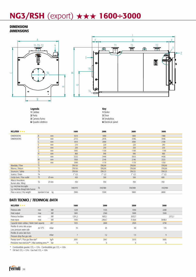
38
NG3/RSH (export) HHH1600÷3000DIMENSIONIDIMENSIONS
Legenda1 Caldaia2 Porta3 Camera fumo6 Quadro elettrico
Key1 Boiler2 Door3 Smokebox6 Electrical panel
PREXTHERM NG3 1600÷2600Disegno / Drawing Nr. 3936616/0Generatore d'acqua calda
Hot water generator rev. 04/03/2011
Pressione max esercizio ** Pressione prova Temperatura progetto
Max working pressure **Hydraulic test pressureDesign temperature
6 bar7,8 bar100 °C
** Pressione max esercizio a richiesta:** Max working pressure on request: 8 bar / 10 bar
KW
dm
KWPotenza utile - Heat output
Capacità totale caldaia - Boiler total capacity
Potenza focolare - Heat input
16001229
1291,2
1925
20001535
1603,1
2600
PREXTHERM NGT 26001950
2033,7
2920Perdite carico lato acqua - Loss pressure water side t 15 °C 70 65 90m barPerdite carico lato fumi - Pressure drop flue gas side 7 7,2 7,5m barPortata fumi * - Flue gas flow-rate * 3091 3947 5010kg/hPressione max esercizio ** - Max working pressure ** 6 6 6bar
6 bar kg 3900 5300 5800Peso a secco - Dry weightT1
T3T4T5
ABC
DN150 DN200 DN200
DN100 DN125 DN1251-1/2" 1-1/2" 1-1/2"450 500 500Ø mm
T2mandata - flowritorno - return
sicurezze - safety
uscita fumo - flue outletscarico - drain
attacco bruciatore - burner attac. fittinglg. min/max boccaglio - lg. min/max draugt tube burner
T6Ø mmAT
TACC
HI -
FITTIN
G
350 350 350340/470 350/480 350/480
E
DIMENSIONI - DIMENSIONS
1610 1800 18002772 2976 33461810 2000 2000210 220 220
Legenda 1 Caldaia 2 Porta 3 Camera Fumo 4 Quadro elettrico
Key 1 Boiler 2 Door 3 Smokebox 4 Electrical panel
* Combustibile gasolio: CO² = 13% - Combustibile gas: CO² = 10%* Oil fuel: CO² = 13% - Gas fuel: CO² = 10%
standard
F 250 250 250G 1005 1100 1100H 860 940 940I 3232 3446 3816M 1950 2140 2140
minmaxminmax
1845 2360 3000
1930 2464,7 3128,8
DN150 DN200 DN200
Q 1000 1170 1170
'
DATI TECNICI / TECHNICAL DATA NG3/RSH HHH 1600 2000 2600 3000
Potenza utile min kW 1229 1535 1950 2280 Heat output max kW 1845 2360 3000 3500 Potenza focolare min kW 1291,2 1603,1 2033,7 2372,1 Heat input max kW 1930 2464,7 3128,8 3648,4 Capacità totale caldaia / Boiler total capacity dm3 1925 2600 2920 4790 Perdite di carico lato acqua
∆t 15°C mbar 70 65 90 135 Loss pressure water side Perdite di carico lato fumi
mbar 7 7,2 7,5 9 Pressure drop flue gas side Portata fumi* / Flue gas flow-rate* kg/h 3091 3947 5010 5685 Pressione max esercizio** / Max working press.** bar 6 6 6 6
* Combustibile gasolio: CO2 = 13% - Combustibile gas: CO2 = 10%* Oil fuel: CO2 = 13% - Gas fuel: CO2 = 10%
NG3/RSH HHH 1600 2000 2600 3000
DIMENSIONI A mm 1610 1800 1800 1980 DIMENSIONS B mm 2772 2976 3346 3946 C mm 1810 2000 2000 2180 E mm 210 220 220 240 F mm 250 250 250 250 G mm 1005 1100 1100 1190 H mm 860 940 940 960 I mm 3232 3446 3816 4436 M mm 1950 2140 2140 2325 Q mm 1000 1170 1170 1350 Mandata / Flow T1 DN150 DN200 DN200 DN200 Ritorno / Return T2 DN150 DN200 DN200 DN200 Sicurezze / Safety T3 DN100 DN125 DN125 DN125 Scarico / Drain T4 1” 1/2 1” 1/2 1” 1/2 1’’ 1/2 Uscita fumi / Flue outlet T5 Ø mm 450 500 500 600 Attacco bruciatore
T6 Ø mm 350 350 350 350 Burner attac. fitting Lg. min/max boccaglio
T6 340/470 350/480 350/480 350/480 Lg. min/max draugt tube burner Peso a secco / Dry weight standard 6 bar kg 3900 5300 5800 8000

39
ACCESSORI A RICHIESTA
nQuadro comandi termostatico. Di tipo termostatico per bruciatori di tipo monostadio e bista-dio, con la possibilità di comandare la pompa impianto.
nQuadro comandi THERMO EBM.Di tipo elettronico per la gestione del generatore (anche con bruciatori modulanti), con controllo a microprocessore; con unità logica alloggiata nella scocca e interfaccia utente, con display LCD, fronte quadro.
nSonda esterna.Per funzionamento a temperatura scorrevole della caldaia, da interfacciare con il quadro comandi THERMO EBM.
nSonda cascata/mandata/bollitore.Da interfacciare con il quadro comandi THERMO EBM dipen-dentemente dalle esigenze.
nQuadro comandi industriale.Per particolari esigenze in merito ad accuratezza di regolazione oppure per installazioni in ambito sicuro.
nQuadro comandi con PLC.Per esigenze specifiche di comunicazione con BMS o sistemi di supervisione.
nTronchetto porta strumenti.In grado di accogliere tutta la strumentazione di regolazione e di sicurezza della caldaia, proponibile in diverse configurazioni.
nEconomizzatore in acciaio inox per l’innalzamento del siste-ma fino al 5% (in base alla temperatura dell’acqua di ritorno dell’impianto) attraverso il recupero di calore dei fumi.
nCollegamento economizzatore completo di prolungamen-to tubazione di ritorno, pompa di circolazione con valvole di intercettazione e collegamento meccanico all’economizzatore realizzato presso nostro stabilimento.
nBruciatore a gas, a gasolio o a nafta.nPiastra porta bruciatore forata secondo le indicazioni del cliente.
ACCESSORIES AVAILABLE ON REQUEST
nThermostatic control panel.Thermostatic controller for single-stage or two-stage burners, with the possibility to control the system pump.
nTHERMO EBM control panel.Electronic for managing the hot water generator (including with modulating burners), with microprocessor control; logical control unit housed inside the casing and user interface with LCD on the front panel.
nOutside probe.For boiler temperature compensation operation, to be con-nected to the THERMO EBM control panel.
nCascade/outlet/storage cylinder probe.Connected to the THERMO EBM control panel based on requirements.
nIndustrial control panel.For special needs regarding precision control or installation in safe environments.
nControl panel with PLC.For specific communication needs to BMS or supervision systems.
nPipe stub for instrument connection.Able to house all the boiler control and safety instruments, available in different configurations.
nStainless steel economiser to increase system efficiency by up to 5% (based on the system return temperature) by reco-vering heat from the flue gas.
nEconomiser connection complete with return pipe exten-sion, circulating pump with on-off valves and mechanical con-nection to the economiser performed directly at our facilities.
nGas, oil or diesel burner.nPerforated burner plate based on customer specifications.

40
Caldaia per acqua calda a tre giri effettivi di fumo - LOW NOxHot water boiler with three flue passes - LOW NOx
Generatore termico a sviluppo orizzontale per la combustione pressurizzata a tre giri di fumo a fiamma passante, con un’ef-ficienza energetica certificata a tre stelle secondo la direttiva 92/42/CEE. Predisposto per funzionare in abbinamento ad un bruciatore ad aria soffiata a combustibile liquido o gassoso. La geometria della camera di combustione, ed il generoso dimen-sionamento, garantiscono un basso carico termico e la possibilità di essere abbinate a bruciatori dotati di tecnologie per la combu-stione a bassi tenori di inquinanti.Gamma composta da 20 modelli con potenze nominali da 92 a 3200 kW. nCorpo caldaia, rivestito esternamente con una protezione in
lamierino di acciaio al carbonio verniciato con polveri epossi-diche e costituito da:tubo per il passaggio del secondo giro fumi con ripresa dal fondo del focolare, dimensionato per ottimizzare i parame-tri di combustione;fascio tubiero per il terzo passaggio fumi posta nella parte superiore e più calda del generatore al fine di evitare condense e dotata di turbolatori in acciaio per l’inalzamento dello scambio convettivo.
Hot water generator with pressurised combustion with three flue gas passes and three-star certified energy efficiency in accordan-ce with directive 92/42/EEC.Ready for operation in combination with a jet burner on liquid or gas fuel. The arrangement and generous sizing of the combu-stion chamber guarantee a low heating load and the possibility to be combined with burners featuring technology for the com-bustion with low polluting emissions.Range consisting of 20 models with rated outputs from 92 to 3200 kW.nBoiler body lined on the outside with carbon steel plate pro- tection painted with epoxy powder coat, and consisting of:
pipe for the second flue pass with intake from the bottom of the furnace, sized to optimise combustion parameters;tube bundle for the third flue gas pass located at the top and hotter part of the hot water generator, so as to prevent condensate forming and fitted with steel turbulators to incre-ase convective heat exchange.
TP3 LN HHH
DISPONIBILE ANCHE IN VERSIONE SCOMPOSTA DA ASSEMBLARE IN CENTRALE
ALSO AVAILABLE IN THE DISMANTLED VERSION TO BE ASSEMBLED IN THE HEATING PLANT

41
nEnergy efficiency exceeding 95%.nMaximum operating pressure 6 bars.nMaximum design temperature 100°C.nFloating combustion chamber with cooled end plate,
volumetric heating load less than 1.1 MW/m3 to ensure atmo-spheric nitrogen oxide emissions less than 80 mg kW/h, in combination with suitable burners.
nThreaded fittings up to 240 kW outputs and flanged fittings complete with counterflanges for larger sizes.nFront door with reversible opening from both sides and inno-
vative closing system with micrometric adjustment on the boiler body. Heat insulation using with material with excellent insulting properties and reduced thermal inertia, protected by refractory material on the furnace side and on the flue gas pass side.
nHeat insulation extended to all parts of the boiler using an 80 mm thick layer of mineral wool on all the plating.
CERTIFICATIONCE mark in accordance with the following directives Gas Appliances (2009/142 EEC)Efficiency (92/42 EEC)Low Voltage (2014/35/EU)Electromagnetic Compatibility (2014/30/EU)
nEfficienza energetica superiore al 95%.nPressione massima di esercizio 6 bar.nTemperatura massima di progetto 100°C.nCamera di combustione a fondo bagnato flottante con
carico termico volumetrico inferiore a 1,1 MW/m3 per garantire valori di emissioni in atmosfera di ossidi azoto inferiori a 80 mg kW/h, in abbinamento ad opportuni bruciatori.
nAttacchi filettati fino alla potenza di 240 kW e flangiati com-pleti di controflange, per taglie di potenza superiori.
nPortellone anteriore con apertura reversibile da ambo i lati ed innovativo sistema di chiusura e regolazione micrometrica sul corpo caldaia. Isolamento termico con materiale ad elevato potere coibentante e ridotta inerzia termica e protezione in materiale refrattario sul lato focolare e sul lato giro fumi.
nIsolamento termico esteso a tutte le parti della caldaia e ottenuto con uno strato di lana minerale dello spessore di 80 mm che avvolge l’intero fasciame.
CERTIFICAZIONIMarcatura CE secondo le Direttive Apparecchi a Gas (2009/142 CEE)Rendimenti (92/42 CEE)Bassa Tensione (2014/35/EU)Compatibilità Elettromagnetica (2014/30/EU)
Ritorno impianto
Central heating return inlet
Attacco sicurezza
Safety connection
Mandata impianto
Central heating flow outlet
Terzo passaggio fumi con turbolatori
Third flue gas pass with turbulators
Secondo passaggio fumi con ripresa posteriore
Second flue gas pass with intake at rear
Focolare a basso carico termicocompletamente bagnato
Completely cooled furnace with low heating load
Isolamento preformato su lato focolare e su lato inversione fumi
Preformed insulation on furnace side and on flue gas reversal side
Portellone con apertura reversibile DX e SX fornito con piastra portabruciatore cieca
Door with reversible opening, R and L, supplied with blind burner anchor plate
Sistema chiusura e regolazione portellone
Door closing and adjustment system
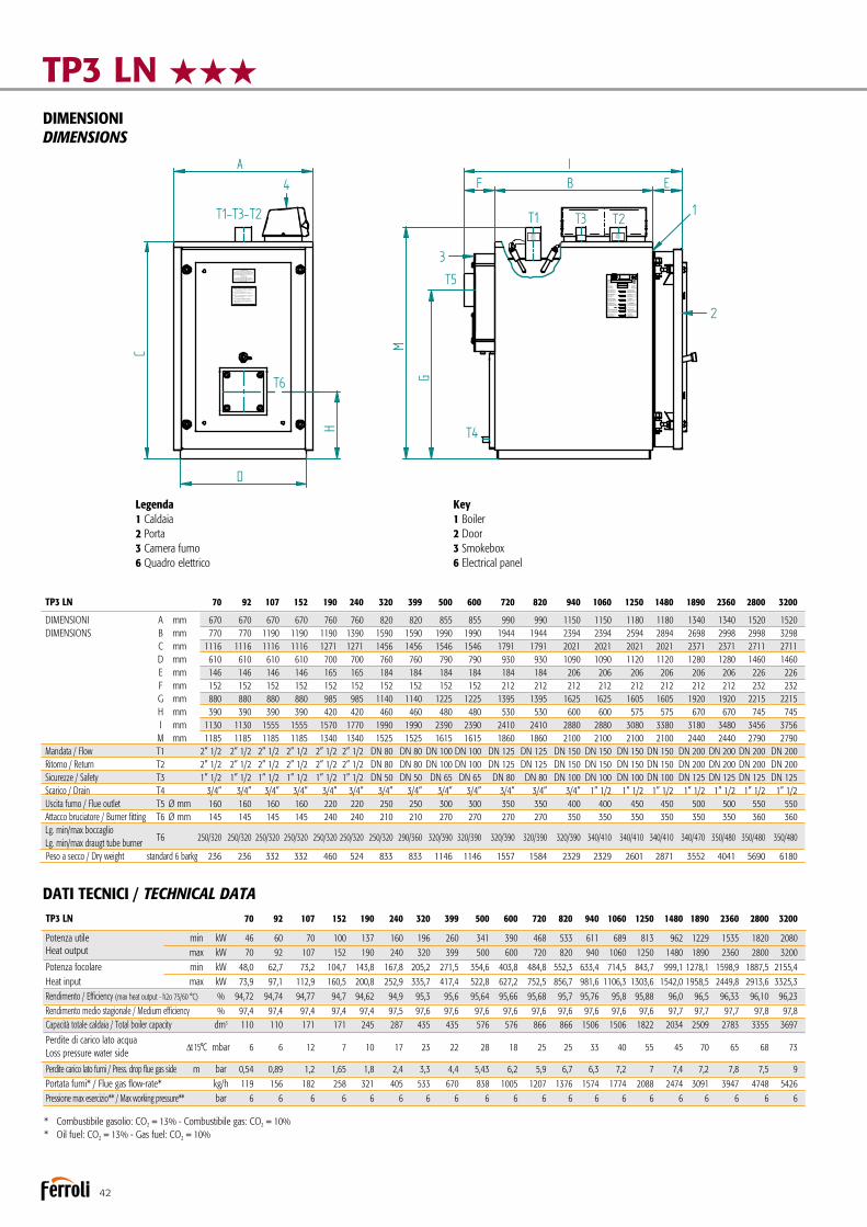
42
TP3 LN HHH DIMENSIONIDIMENSIONS
* Combustibile gasolio: CO2 = 13% - Combustibile gas: CO2 = 10%* Oil fuel: CO2 = 13% - Gas fuel: CO2 = 10%
TP3 LN 70 92 107 152 190 240 320 399 500 600 720 820 940 1060 1250 1480 1890 2360 2800 3200
DIMENSIONI A mm 670 670 670 670 760 760 820 820 855 855 990 990 1150 1150 1180 1180 1340 1340 1520 1520 DIMENSIONS B mm 770 770 1190 1190 1190 1390 1590 1590 1990 1990 1944 1944 2394 2394 2594 2894 2698 2998 2998 3298 C mm 1116 1116 1116 1116 1271 1271 1456 1456 1546 1546 1791 1791 2021 2021 2021 2021 2371 2371 2711 2711 D mm 610 610 610 610 700 700 760 760 790 790 930 930 1090 1090 1120 1120 1280 1280 1460 1460 E mm 146 146 146 146 165 165 184 184 184 184 184 184 206 206 206 206 206 206 226 226 F mm 152 152 152 152 152 152 152 152 152 152 212 212 212 212 212 212 212 212 232 232 G mm 880 880 880 880 985 985 1140 1140 1225 1225 1395 1395 1625 1625 1605 1605 1920 1920 2215 2215 H mm 390 390 390 390 420 420 460 460 480 480 530 530 600 600 575 575 670 670 745 745 I mm 1130 1130 1555 1555 1570 1770 1990 1990 2390 2390 2410 2410 2880 2880 3080 3380 3180 3480 3456 3756 M mm 1185 1185 1185 1185 1340 1340 1525 1525 1615 1615 1860 1860 2100 2100 2100 2100 2440 2440 2790 2790 Mandata / Flow T1 2” 1/2 2” 1/2 2” 1/2 2” 1/2 2” 1/2 2” 1/2 DN 80 DN 80 DN 100 DN 100 DN 125 DN 125 DN 150 DN 150 DN 150 DN 150 DN 200 DN 200 DN 200 DN 200 Ritorno / Return T2 2” 1/2 2” 1/2 2” 1/2 2” 1/2 2” 1/2 2” 1/2 DN 80 DN 80 DN 100 DN 100 DN 125 DN 125 DN 150 DN 150 DN 150 DN 150 DN 200 DN 200 DN 200 DN 200 Sicurezze / Safety T3 1” 1/2 1” 1/2 1” 1/2 1” 1/2 1” 1/2 1” 1/2 DN 50 DN 50 DN 65 DN 65 DN 80 DN 80 DN 100 DN 100 DN 100 DN 100 DN 125 DN 125 DN 125 DN 125 Scarico / Drain T4 3/4” 3/4” 3/4” 3/4” 3/4” 3/4” 3/4” 3/4” 3/4” 3/4” 3/4” 3/4” 3/4” 1” 1/2 1” 1/2 1” 1/2 1” 1/2 1” 1/2 1” 1/2 1” 1/2 Uscita fumo / Flue outlet T5 Ø mm 160 160 160 160 220 220 250 250 300 300 350 350 400 400 450 450 500 500 550 550 Attacco bruciatore / Burner fitting T6 Ø mm 145 145 145 145 240 240 210 210 270 270 270 270 350 350 350 350 350 350 360 360 Lg. min/max boccaglio
T6 250/320 250/320 250/320 250/320 250/320 250/320 250/320 290/360 320/390 320/390 320/390 320/390 320/390 340/410 340/410 340/410 340/470 350/480 350/480 350/480 Lg. min/max draugt tube burner Peso a secco / Dry weight standard 6 barkg 236 236 332 332 460 524 833 833 1146 1146 1557 1584 2329 2329 2601 2871 3552 4041 5690 6180
DATI TECNICI / TECHNICAL DATA
Legenda1 Caldaia2 Porta3 Camera fumo6 Quadro elettrico
Key1 Boiler2 Door3 Smokebox6 Electrical panel
TP3 LN 92÷2360Disegno / Drawing Nr. 3936663/0Generatore d'acqua calda
Hot water generator rev. 11/04/2011
Pressione max esercizio ** Pressione prova Temperatura progetto
Max working pressure **Hydraulic test pressureDesign temperature
6 bar7,8 bar100 °C
** Pressione max esercizio a richiesta:** Max working pressure on request: 8 bar / 10 bar
KW
dm
KWPotenza utile - Heat output
Capacità totale caldaia - Boiler total capacity
Potenza focolare - Heat input
9260
10770
152100
190137
240160
320196
399260
500341
600390
PREXTHERM NGT 720468
820533
940611
1060689
Perdite carico lato acqua - Loss pressure water side t 15 °C m barPerdite carico lato fumi - Pressure drop flue gas side m barPortata fumi * - Flue gas flow-rate * kg/hPressione max esercizio ** - Max working pressure ** bar
6 bar kgPeso a secco - Dry weightT1
T3T4T5
ABC
Ø mm
T2mandata - flowritorno - return
sicurezze - safety
uscita fumo - flue outletscarico - drain
attacco bruciatore - burner attac. fittinglg. min/max boccaglio - lg. min/max draugt tube burner
T6Ø mmAT
TACC
HI -
FITTIN
G
250/320 250/320 250/320 250/320 250/320 250/320 390/360 320/390 320/390 320/390 320/390 340/410290/360
DE
DIMENSIONI - DIMENSIONS
670 670 670 760 760 820 860 860 980 980 1100 1100820
Legenda 1 Caldaia 2 Porta 3 Camera Fumo 4 Quadro elettrico
Key 1 Boiler 2 Door 3 Smokebox 4 Electrical panel
* Combustibile gasolio: CO² = 13% - Combustibile gas: CO² = 10%* Oil fuel: CO² = 13% - Gas fuel: CO² = 10%
standard
1250813
340/4101140
1480962
340/4101140
18901229
340/4701260
23601535
350/4801260
FGHIM
minmaxminmax
92 107 152 190 240 320 399 500 600 720 820 940 1060 1250 1480 1845 236063,7 74,3 105.8 144,4 168,4 206 272,6 357 407,9 489,8 558,4 638,9 719,9 848,2 1004,4 1291,2 1603,197,7 113,5 160,8 200,2 252,6 336,4 418,4 523,5 627,6 753,6 859,1 982,9 1107,6 1304,2 1545,2 1930 2464,7107 107 168 246 289 409 409 533 533 864 864 1385 1385 1594 1780 1923 2141
6 12 7 10 17 23 22 28 18 25 25 33 40 55 45 70 650,7 1,2 1,2 2,3 3,3 3,5 4,3 4,8 4,5 5,6 5,4 6 6,5 6,5 6,8 7 7,2156 182 258 321 405 539 670 838 1005 1207 1376 1574 1774 2088 2474 3091 3947
6 6 6 6 6 6 6 6 6 6 6 6 6 6 6 6 6240 240 330 450 510 790 790 1090 1090 1500 1500 2140 2140 2470 2730 3510 3840
2-1/2" 2-1/2" 2-1/2" 2-1/2" 2-1/2" DN 80 DN 80 DN100 DN100 DN125 DN125 DN150 DN150 DN150 DN150 DN200 DN2002-1/2" 2-1/2" 2-1/2" 2-1/2" 2-1/2" DN 80 DN 80 DN100 DN100 DN125 DN125 DN150 DN150 DN150 DN150 DN200 DN2001-1/2" 1-1/2" 1-1/2" 1-1/2" 1-1/2" DN 50 DN 50 DN 65 DN 65 DN 80 DN 80 DN100 DN100 DN100 DN100 DN125 DN1253/4" 3/4" 3/4" 3/4" 3/4" 3/4" 3/4" 3/4" 3/4" 3/4" 3/4" 3/4" 1-1/2" 1-1/2" 1-1/2" 1-1/2" 1-1/2"160 160 160 220 220 250 250 300 300 350 350 400 400 450 450 500 500145 145 150 150 150 240 240 240 210 210 270 270 270 270 350 350 350
766 766 1186 1186 1386 1586 1986 1986 1940 1940 2390 23901586 2590 2890 2700 30001051 1051 1051 1221 1221 1386 1466 1466 1746 1746 1931 19311386 1991 1991 2271 2271610 610 610 700 700 760 800 800 930 930 1040 1040760 1080 1080 1200 1200141 141 141 160 160 179 179 179 179 179 206 206179 206 206 216 216153 153 153 153 153 153 153 153 213 213 213 213153 213 213 243 243815 815 815 935 935 1080 1140 1140 1350 1350 1480 14801080 1520 1520 1740 1740325 325 325 370 370 400 420 420 485 485 540 540400 560 560 630 6301060 1060 1480 1502 1699 1918 2318 2318 2332 2332 2810 28101918 3010 3010 3160 31601120 1120 1120 1290 1290 1455 1535 1535 1815 1815 2060 20601455 2120 2120 2400 2400
3 Giri di fumo3 Stelle
kt rnhjgbnfy bt
Pf djlc rj q yjv t h
Nt gkjghjbpdjlbntk myj cnm
Gjkt pyf z N t gkj dfz vj oyj c nm
Vfrc = hf,j xt t l fdkt ybt
Vfrc = hf,j xf z ntv gt hfnehf
Jghtccj djx yjt l fdkty bt #Lf nf
Vjl tk m
Rjl
J, mtv rj nkj dj q d jls
'
TP3 LN 70 92 107 152 190 240 320 399 500 600 720 820 940 1060 1250 1480 1890 2360 2800 3200
Potenza utile min kW 46 60 70 100 137 160 196 260 341 390 468 533 611 689 813 962 1229 1535 1820 2080 Heat output max kW 70 92 107 152 190 240 320 399 500 600 720 820 940 1060 1250 1480 1890 2360 2800 3200 Potenza focolare min kW 48,0 62,7 73,2 104,7 143,8 167,8 205,2 271,5 354,6 403,8 484,8 552,3 633,4 714,5 843,7 999,1 1278,1 1598,9 1887,5 2155,4 Heat input max kW 73,9 97,1 112,9 160,5 200,8 252,9 335,7 417,4 522,8 627,2 752,5 856,7 981,6 1106,3 1303,6 1542,0 1958,5 2449,8 2913,6 3325,3
Rendimento / Efficiency (max heat output - h2o 75/60 °C) % 94,72 94,74 94,77 94,7 94,62 94,9 95,3 95,6 95,64 95,66 95,68 95,7 95,76 95,8 95,88 96,0 96,5 96,33 96,10 96,23 Rendimento medio stagionale / Medium efficiency % 97,4 97,4 97,4 97,4 97,4 97,5 97,6 97,6 97,6 97,6 97,6 97,6 97,6 97,6 97,6 97,7 97,7 97,7 97,8 97,8 Capacità totale caldaia / Total boiler capacity dm3 110 110 171 171 245 287 435 435 576 576 866 866 1506 1506 1822 2034 2509 2783 3355 3697 Perdite di carico lato acqua
∆t 15°C mbar 6 6 12 7 10 17 23 22 28 18 25 25 33 40 55 45 70 65 68 73 Loss pressure water side
Perdite carico lato fumi / Press. drop flue gas side m bar 0,54 0,89 1,2 1,65 1,8 2,4 3,3 4,4 5,43 6,2 5,9 6,7 6,3 7,2 7 7,4 7,2 7,8 7,5 9 Portata fumi* / Flue gas flow-rate* kg/h 119 156 182 258 321 405 533 670 838 1005 1207 1376 1574 1774 2088 2474 3091 3947 4748 5426 Pressione max esercizio** / Max working pressure** bar 6 6 6 6 6 6 6 6 6 6 6 6 6 6 6 6 6 6 6 6

43
ACCESSORI A RICHIESTA
nQuadro comandi termostatico. Di tipo termostatico per bruciatori di tipo monostadio e bista-dio, con la possibilità di comandare la pompa impianto.
nQuadro comandi THERMO EBM.Di tipo elettronico per la gestione del generatore (anche con bruciatori modulanti), con controllo a microprocessore; con unità logica alloggiata nella scocca e interfaccia utente, con display LCD, fronte quadro.
nSonda esterna.Per funzionamento a temperatura scorrevole della caldaia, da interfacciare con il quadro comandi THERMO EBM.
nSonda cascata/mandata/bollitore.Da interfacciare con il quadro comandi THERMO EBM dipen-dentemente dalle esigenze.
nQuadro comandi industriale.
Per particolari esigenze in merito ad accuratezza di regolazione oppure per installazioni in ambito sicuro.
nQuadro comandi con PLC.Per esigenze specifiche di comunicazione con BMS o sistemi di supervisione.
nTronchetto porta strumenti.In grado di accogliere tutta la strumentazione di regolazione e di sicurezza della caldaia, proponibile in diverse configurazioni.
nEconomizzatore in acciaio inox per l’innalzamento del siste-ma fino al 5% (in base alla temperatura dell’acqua di ritorno dell’impianto) attraverso il recupero di calore dei fumi.
nCollegamento economizzatore completo di prolungamen-to tubazione di ritorno, pompa di circolazione con valvole di intercettazione e collegamento meccanico all’economizzatore realizzato presso nostro stabilimento.
nBruciatore a gas, a gasolio o a nafta.nPiastra porta bruciatore forata secondo le indicazioni del
cliente.
ACCESSORIES AVAILABLE ON REQUEST
nThermostatic control panel.Thermostatic controller for single-stage or two-stage burners, with the possibility to control the system pump.
nTHERMO EBM control panel.Electronic for managing the hot water generator (including with modulating burners), with microprocessor control; logical control unit housed inside the casing and user interface with LCD on the front panel.
nOutside probe.For boiler temperature compensation operation, to be con-nected to the THERMO EBM control panel.
nCascade/outlet/storage cylinder probe.Connected to the THERMO EBM control panel based on requirements.
nIndustrial control panel.For special needs regarding precision control or installation in safe environments.
nControl panel with PLC.For specific communication needs to BMS or supervision systems.
nPipe stub for instrument connection.Able to house all the boiler control and safety instruments,available in different configurations.
nStainless steel economiser to increase system efficiency by up to 5% (based on the system return temperature) by reco-vering heat from the flue gas.
nEconomiser connection complete with return pipe exten-sion, circulating pump with on-off valves and mechanical con-nection to the economiser performed directly at our facilities.
nGas, oil or diesel burner.nPerforated burner plate based on customer specifications.

44
Caldaia per acqua calda a tre giri effettivi di fumoHot water boiler with three flue passes
PREXTHERM T3G F
Generatore termico a combustione pressurizzata ed elevata effi-cienza energetica a tre giri di fumo. Predisposto per funzionare in abbinamento ad un bruciatore ad aria soffiata a combustibile liquido o gassoso. La geometria della camera di combustione a fondo bagnato, ed il generoso dimensionamento, garantiscono un basso carico termico e la possibilità, in abbinamento ad un bruciatore idoneo, di realizzare una combustione a basse emis-sioni di NOx. Gamma composta da 14 modelli con potenze nominali da 1.200 a 9.000 kW.nCorpo caldaia interamente in acciaio, completamente rivestito
con un materassino in lana minerale ad alta densità, protetto da lamierino INOX, le dispersioni verso l’ambiente sono molto contenute.
nEfficienza energetica superiore al 92%nPressione massima di esercizio 6 bar, a richiesta fino a 10 bar.nTemperatura massima di progetto: 110°C.nCamera di combustione costituita da un grande focolare,
rinforzato con giunti omega, a garanzia di un utilizzo a bassi carichi termici.
Hot water generator with pressurised combustion and high energy efficiency, three flue gas passes. Ready for operation in combination with a jet burner on liquid or gas fuel. The arrangement and generous sizing of the combustion cham-ber with cooled end plate guarantee a low heating load and the possibility, when combined with a suitable burner, to ensure combustion with low NOx emissions.Range consisting of 14 models with rated outputs from 1,200 to 9,000 kW.
nBoiler body made entirely from steel, completely lined witha layer of high-density mineral wool, protected by stainless steel plate, meaning very low heat loss to the surrounding environment.
nEnergy efficiency exceeding 92%nMaximum operating pressure 6 bars, up to 10 bars on request.nMaximum design temperature: 110°C.nCombustion chamber consisting of a large furnace reinforced
with omega joints to guarantee operation at low heating loads.
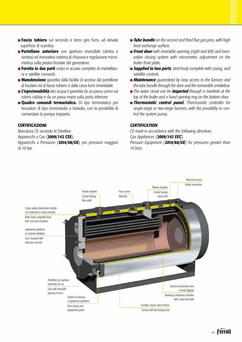
45
nTube bundle on the second and third flue gas pass, with high heat exchange surface.nFront door with reversible opening (right and left) and inno-
vative closing system with micrometric adjustment on the boiler front plate.
nSupplied in two parts, steel body complete with casing, and satellite controls.nMaintenance guaranteed by easy access to the furnace and
the tube bundle through the door and the removable smokebox.nThe water circuit can be inspected through a manhole at the
top of the boiler and a hand opening ring on the bottom door.nThermostatic control panel. Thermostatic controller for
single-stage or two-stage burners, with the possibility to con-trol the system pump.
CERTIFICATIONCE mark in accordance with the following directives Gas Appliances (2009/142 EEC), Pressure Equipment (2014/68/UE) for pressures greater than 10 bars.
nFascio tubiero sul secondo e terzo giro fumi, ad elevata superficie di scambio.
nPortellone anteriore con apertura reversibile (destra e sinistra) ed innovativo sistema di chiusura e regolazione micro-metrica sulla piastra frontale del generatore.
nFornita in due parti corpo in acciaio completo di mantellatu- ra e satellite comandi.nManutenzione garantita dalla facilità di accesso dal portellone
al focolare ed al fascio tubiero e dalla cassa fumi smontabile.nL’ispezionabilità lato acqua è garantita da un passo uomo sul colmo caldaia e da un passa mano sulla porta inferiore.nQuadro comandi termostatico. Di tipo termostatico per
bruciatori di tipo monostadio e bistadio, con la possibilità di comandare la pompa impianto.
CERTIFICAZIONIMarcatura CE secondo le Direttive Apparecchi a Gas (2009/142 CEE), Apparecchi a Pressione (2014/68/UE) per pressioni maggiori di 10 bar.
Corpo caldaia interamente rivestito con materassino in lana minerale
Boiler body completely linedwith rock wool insulation
Isolamento portellone in cemento refrattario
Door insulated with refractory concrete
Andata impianto
Central heating flow outlet
Passo uomo
Manhole
Ritorno impianto
Central heating return inlet
Attacchi sicurezze
Safety connections
Camera di inversione fumi a fondo bagnato
Reversing combustion chamber with cooled end plate
Focolare a basso carico termico
Furnace with low heating load
Portellone con aperturareversibile dx e sx
Door with reversibleopening, R and L
Sistema di chiusurae regolazione portellone
Door closing and adjustment system

46
PREXTHERM T3G FDIMENSIONIDIMENSIONS
PREXTHERM T3G F 1000÷9000 Pressione max esercizio Pressione prova Temperatura progetto
Disegno / Drawing Nr. 3936608/0Generatore d'acqua caldaHot water generator
Max working pressureHydraulic test pressureDesign temperature
6 bar9 bar100 °C
rev. 10/02/2011
KWdm
KWPotenza utile - Heat output
Capacità totale caldaia - Boiler total capacityPotenza focolare - Heat input
1200120012972200
1400140015132450
1750175019023250
2000200021623650
2300230025004800
2800280030275250
3400340037005500
4000400043547250
4600460050007600
PREXTHERM T3G 52005200565310500
60006000652212100
700070007609
13500
800080008697
17150
900090009783
18200Perdite carico lato acqua - Loss pressure water side t 15 °C 35 52 45 50 70 65 90 130 170 140 120 150 210 230m barPerdite carico lato fumi - Pressure drop flue gas side 4,5 6,3 5,5 7,4 4 5,2 6,1 5,4 7,5 8,2 6,1 8,4 8,2 8,5m barPortata* fumi - Flue gas flow-rate* 2078 2424 3047 3463 3982 4848 5887 6926 7964 9003 9787 11418 13049 14680kg/hPressione max esercizio - Max working pressure 6/10 6/10 6/10 6/10 6/10 6/10 6/10 6/10 6/10 6/10 6/10 6/10 6/10 6/10bar
10 bar6 bar kg
kg3750 3900 5000 5250 5400 5950 7200 8700 9500 11900 13800 14700 17500 197004150 4400 5550 6000 6300 6700 8000 9600 10800 12700 15000 16600 20500 21800
Peso a secco - Dry weight
T1
T3T4T5
ABC
DN125 DN125 DN150 DN150 DN150 DN200 DN200 DN200 DN200 DN250 DN250 DN250 DN250 DN250
DN40 DN40 DN40 DN40 DN50 DN50 DN50 DN65 DN65 DN65 DN65 DN80 DN80 DN80DN40 DN40 DN40 DN40 DN40 DN40 DN40 DN40 DN40 DN40 DN40 DN40 DN40 DN40400 400 450 450 450 500 600 600 700 700 700 800 900Ø mm 500
T2 DN125 DN125 DN150 DN150 DN150 DN200 DN200 DN200 DN200 DN250 DN250 DN250 DN250 DN250mandata - flowritorno - return
sicurezze - safety
uscita fumo - flue outletscarico - drain
attacco bruciatore - burner attac. fittinglg. min/max boccaglio - lg. min/max draugt tube burner
T6Ø mmAT
TACC
HI -
FITTIN
G
220 220 220 240 240 240 300 360 360 360 430 430 430270280/380 280/380 280/380 280/380 280/380 280/380 310/410 310/410 390/490 390/490 390/490 390/490 390/490280/380
DE
DIMENSIONI - DIMENSIONS
1560 1560 1760 1760 2010 2010 2220 2220 2500 2500 2500 2710 271020101870 1870 2090 2090 2280 2280 2590 2590 2780 2780 2780 3040 304022803280 3530 3680 3930 3940 4260 4930 5180 5730 6050 6530 6990 72904510790 790 875 875 890 890 1070 1070 1105 1105 1105 1220 12208901350 1350 1550 1550 1650 1650 1900 1900 2140 2140 2140 2140 21401650
Legenda 1 Caldaia 2 Porta 3 Camera Fumo 4 Quadro elettrico
Key 1 Boiler 2 Door 3 Smokebox 4 Electrical panel
Legenda1 Caldaia2 Porta3 Camera fumo4 Quadro elettrico
Key1 Boiler2 Door3 Smokebox4 Electrical panel
* Combustibile gasolio: CO2 = 13% - combustibile gas: CO2 = 10%* Oil fuel: CO2 = 13% - Gas fuel: CO2 = 10%
PREXTHERM T 3G F 1200 1400 1750 2000 2300 2800 3400 4000 4600 5200 6000 7000 8000 9000
DIMENSIONI / DIMENSIONS A mm 1560 1560 1760 1760 2010 2010 2010 2220 2220 2500 2500 2500 2710 2710
B mm 1870 1870 2090 2090 2280 2280 2280 2590 2590 2780 2780 2780 3040 3040
C mm 3280 3530 3680 3930 3940 4260 4510 4930 5180 5730 6050 6530 6990 7290
D mm 790 790 875 875 890 890 890 1070 1070 1105 1105 1105 1220 1220
E mm 1350 1350 1550 1550 1650 1650 1650 1900 1900 2140 2140 2140 2140 2140
ATTACCHI / FITTINGS
Mandata / Flow T1 DN 125 125 150 150 150 200 200 200 200 250 250 250 250 250
Ritorno / Return T2 DN 125 125 150 150 150 200 200 200 200 250 250 250 250 250
Sicurezze / Safety T3 DN 40 40 40 40 50 50 50 65 65 65 65 80 80 80
Scarico / Drain T4 DN 40 40 40 40 40 40 40 40 40 40 40 40 40 40
Uscita fumo / Flue outlet T5 Ø mm 400 400 450 450 450 500 500 600 600 700 700 700 800 900
Attacco bruciatore / Burner attacc. fitting T6
ů mm 350 350 360 360 375 375 375 430 430 430 475 475 495 495
Lg. min/max boccaglio / Lg. min/max draught tube burner 280/380 280/380 280/380 280/380 280/380 280/380 280/380 310/410 310/410 390/490 390/490 390/490 390/490 390/490
Peso a secco / Dry weight
standard 6 bar kg 3750 3900 5000 5250 5400 5950 7200 8700 9500 11900 13800 14700 17500 19700
optional 10 bar kg 4150 4400 5550 6000 6300 6700 8000 9600 10800 12700 15000 16600 20500 21800
DATI TECNICITECHNICAL DATA
PREXTHERM T 3G F 1200 1400 1750 2000 2300 2800 3400 4000 4600 5200 6000 7000 8000 9000
Potenza utile / Heat output kW 1200 1400 1750 2000 2300 2800 3400 4000 4600 5200 6000 7000 8000 9000
Potenza focolare / Heat input kW 1297 1513 1902 2162 2500 3027 3700 4354 5000 5653 6522 7609 8697 9783
Capacità totale caldaia / Boiler total capacity dm3 2200 2450 3250 3650 4800 5250 5500 7250 7600 10500 12100 13500 17150 18200
Perdite di carico lato acqua ∆t 15°C mbar 35 52 45 50 70 65 90 130 170 140 120 150 210 230
Loss pressure water side
Perdite di carico lato fumi / Press. drop flue gas side mbar 4,5 6,3 5,5 7,4 4 5,2 6,1 5,4 7,5 8,2 6,1 8,4 8,2 8,5
Portata fumi* / Flue gas flow-rate* kg/h 2078 2424 3047 3463 3982 4848 5887 6926 7964 9003 9787 11418 13049 14680
Pressione max esercizio / Max working pressure bar 6/10 6/10 6/10 6/10 6/10 6/10 6/10 6/10 6/10 6/10 6/10 6/10 6/10 6/10

47
ACCESSORI A RICHIESTA
nQuadro comandi THERMO EBM.Di tipo elettronico per la gestione del generatore (anche con bruciatori modulanti), con controllo a microprocessore; con unità logica alloggiata nella scocca e interfaccia utente, con display LCD, fronte quadro.
nSonda esterna.Per funzionamento a temperatura scorrevole della caldaia, da interfacciare con il quadro comandi THERMO EBM.
nSonda cascata/mandata/bollitore.Da interfacciare con il quadro comandi THERMO EBM dipen-dentemente dalle esigenze.
nQuadro comandi industriale.
Per particolari esigenze in merito ad accuratezza di regolazione oppure per installazioni in ambito sicuro.
nQuadro comandi con PLC.Per esigenze specifiche di comunicazione con BMS o sistemi di supervisione.
nTronchetto porta strumenti.In grado di accogliere tutta la strumentazione di regolazione e di sicurezza della caldaia, proponibile in diverse configurazioni.
nEconomizzatore in acciaio inox per l’innalzamento del siste-ma fino al 5% (in base alla temperatura dell’acqua di ritorno dell’impianto) attraverso il recupero di calore dei fumi.
nCollegamento economizzatore completo di prolungamen-to tubazione di ritorno, pompa di circolazione con valvole di intercettazione e collegamento meccanico all’economizzatore realizzato presso nostro stabilimento.
nBruciatore a gas, a gasolio o a nafta.nPiastra porta bruciatore forata secondo le indicazioni del cliente.nScala e passerella per accedere in sicurezza alla pedana cal- pestabile sopra la caldaia.nCassa fumi posteriore completamente rivestita con mate- rassino in lana minerale ad alta densità.nAttacco camino verticale.
ACCESSORIES AVAILABLE ON REQUEST
nTHERMO EBM control panel.Electronic for managing the hot water generator (including with modulating burners), with microprocessor control; logical control unit housed inside the casing and user interface with LCD on the front panel.
nOutside probe.For boiler temperature compensation operation, to be con-nected to the THERMO EBM control panel.
nCascade/outlet/storage cylinder probe.Connected to the THERMO EBM control panel based on requirements.
nIndustrial control panel.For special needs regarding precision control or installation in safe environments.
nControl panel with PLC.For specific communication needs to BMS or supervision systems.
nPipe stub for instrument connection.Able to house all the boiler control and safety instruments, available in different configurations.
nStainless steel economiser to increase system efficiency by up to 5% (based on the system return temperature) by reco-vering heat from the flue gas.
nEconomiser connection complete with return pipe exten-sion, circulating pump with on-off valves and mechanical con-nection to the economiser performed directly at our facilities.
nGas, oil or diesel burner.nPerforated burner plate based on customer specifications.nLadder and walkway for safe access to the walkable plat-
form on top of the boiler.nRear smokebox completely lined with high density mineral wool insulation.nVertical flue connection.

48
Caldaia per acqua calda a tre giri effettivi di fumoHot water boiler with three flue passes
PREXTHERM T3G N
Generatore termico a combustione pressurizzata ed elevata effi-cienza energetica a tre giri di fumo. Predisposto per funzionare in abbinamento ad un bruciatore ad aria soffiata a combustibile liqui-do o gassoso. La geometria della camera di combustione a fondo bagnato, ed il generoso dimensionamento, garantiscono un basso carico termico e la possibilità, in abbinamento ad un bruciatore idoneo, di realizzare una combustione a basse emissioni di NOx. Gamma composta da 7 modelli con potenze nominali da 6.000 a 15.000 kW.nCorpo caldaia interamente in acciaio, completamente rivesti-
to con un materassino in lana minerale ad alta densità, protetto da lamierino INOX, le dispersioni verso l’ambiente sono molto contenute.
nEfficienza energetica superiore al 92%.nPressione massima di esercizio 6 bar, a richiesta fino a 10 bar.nTemperatura massima di progetto: 110°C.nCamera di combustione costituita da un grande focolare,
rinforzato con giunti omega, a garanzia di un utilizzo a bassi carichi termici.
Hot water generator with pressurised combustion and high energy efficiency, three flue gas passes. Ready for operation in combination with a jet burner on liquid or gas fuel. The arrangement and generous sizing of the combustion chamber with cooled end plate guarantee a low heating load and the possibility, when combined with a suitable burner, to ensure combustion with low NOx emissions.Range consisting of 7 models with rated outputs from 6,000 to 15,000 kW.nBoiler body made entirely from steel, completely lined with
a layer of high-density mineral wool, protected by stainless steel plate, meaning very low heat loss to the surrounding environment.
nEnergy efficiency exceeding 92%.nMaximum operating pressure 6 bars, up to 10 bars on
request.nMaximum design temperature: 110°C.nCombustion chamber consisting of a large furnace reinforced with
omega joints to guarantee operation at low heating loads.

49
nTube bundle on the second and third flue gas pass, with high heat exchange surface.nLarge inspection doors both on the front, for flue gas rever-
sal from the second to third pass, and at the rear for the smokebox.
nRear manhole for inspecting the furnace.nSupplied in two parts, steel body complete with casing, and satellite controls.nThe water circuit can be inspected through a manhole at the top of the boiler and a hand opening ring at the bottom.nRear smokebox completely lined with high density mineral
wool insulation.nThermostatic control panel. Thermostatic controller for
single-stage or two-stage burners, with the possibility to con-trol the system pump.
CERTIFICATIONCE mark in accordance with the following directives Gas Appliances (2009/142 EEC), for heat output ≤ 10 MW.Pressure Equipment (2014/68/UE) for pressures greater than 10 bars.
nFascio tubiero sul secondo e terzo giro fumi, ad elevata superficie di scambio.
nGrandi portelli di ispezione sia nella parte anteriore, di inversione dei fumi dal secondo al terzo giro, che in quella posteriore di raccolta fumi.
nPasso d’uomo posteriore per ispezione del focolare.nFornita in due parti corpo in acciaio, completo di mantella-
tura e satellite comandi.nL’ispezionabilità lato acqua è garantita da un passo uomo sul
colmo caldaia e da un passa mano sulla parte inferiore.nCassa fumi posteriore completamente rivestita con mate-
rassino in lana minerale ad alta densità.nQuadro comandi termostatico. Di tipo termostatico per
bruciatori di tipo monostadio e bistadio, con la possibilità di comandare la pompa impianto.
CERTIFICAZIONIMarcatura CE secondo le Direttive Apparecchi a Gas (2009/142 CEE), fino a 10 MW. Apparecchi a Pressione (2014/68/UE) per pressioni maggiori di 10 bar.
Corpo caldaia interamente rivestito con materassino in lana minerale
Boiler body completely lined with rock wool insulation
Ampi portelli di chiusura e ispezione passaggio fumi
Large closing and flue gas inspection doors
Andata impianto
Central heatingflow outlet
Passo uomo
Manhole
Ritorno impianto
Central heating return inlet
Attacchi sicurezze
Safety connections
Camera di inversione fumi a fondo bagnato
Reversing combustion chamber with cooled end plate
Focolare a basso carico termico
Furnace with low heating load

50
PREXTHERM T3G NDIMENSIONIDIMENSIONS
Legenda1 Caldaia2 Porta3 Camera fumo4 Quadro elettrico
Key1 Boiler2 Door3 Smokebox4 Electrical panel
* Combustibile gasolio: CO2 = 13% - combustibile gas: CO2 = 10%* Oil fuel: CO2 = 13% - Gas fuel: CO2 = 10%** Dimensioni superiori fino a 21 MW verifica fattibilità su richiesta** On request we evaluate the feasibility up to 21 MW
PREXTHERM T 3G N 6000 7000 8000 9000 10000 12000 15000
DIMENSIONI / DIMENSIONS A mm 2500 2500 2710 2710 2710 2860 3260
B mm 2780 2780 3040 3040 3040 3200 3700
C mm 6050 6530 6990 7290 7290 7860 8640
D mm 1105 1105 1220 1220 1220 1240 1382
E mm 2140 2140 2140 2140 2140 2860 2800
ATTACCHI / FITTINGS
Mandata / Flow T1 DN 250 250 250 250 300 300 350
Ritorno / Return T2 DN 250 250 250 250 300 300 350
Sicurezze / Safety T3 DN 65 80 80 80 100 80 100
Scarico / Drain T4 DN 40 40 40 40 40 40 65
Uscita fumo / Flue outlet T5 Ø mm 700 700 800 900 900 900 1000
Peso a secco / Dry weight
standard 6 bar kg 13800 14700 17500 19700 23000 26000 33000
optional 10 bar kg 15000 16600 20500 21800 25000 28000 36000
DATI TECNICITECHNICAL DATA
PREXTHERM T 3G N 6000 7000 8000 9000 10000 12000 15000
Potenza utile / Heat output kW 6000 7000 8000 9000 10000 12000 15000
Potenza focolare / Heat input kW 6522 7609 8697 9783 10870 13044 16305
Capacità totale caldaia / Boiler total capacity dm3 12100 13500 17150 18600 21600 23000 31600
Perdite di carico lato acqua ∆t 15°C mbar 120 150 210 230 180 230
250
Loss pressure water side
Perdite di carico lato fumi / Press. drop flue gas side mbar 6,1 8,4 8,2 8,5 8,7 8,9 11,5
Portata fumi* / Flue gas flow-rate* kg/h 9787 11418 13049 14680 16311 17950 23500
Pressione max esercizio / Max working pressure bar 6 6 6 6 6 6 6
PREXTHERM T3G N 6000÷19500Disegno / Drawing Nr. 3936625/0Generatore d'acqua calda
Hot water generator rev. 24-02-2011
KWdm
KWPotenza utile - Heat output
Capacità totale caldaia - Boiler total capacityPotenza focolare - Heat input
PREXTHERM T3G 195001950021197
---Perdite carico lato acqua - Loss pressure water side t 15 °C ---m barPerdite carico lato fumi - Pressure drop flue gas side ---m barPortata fumi * - Flue gas flow-rate * ---kg/hPressione max esercizio ** - Max working pressure ** 6bar
10 bar6 bar kg
kg------
Peso a secco - Dry weight
T1
T3T4T5ABC
---
---------Ø mm
T2 ---mandata - flowritorno - return
sicurezze - safety
uscita fumo - flue outletscarico - drain
DE
DIMENSIONI - DIMENSIONS
---------------
* Combustibile gasolio: CO² = 13% - Combustibile gas: CO² = 10%* Oil fuel: CO² = 13% - Gas fuel: CO² = 10%
standardoptional
Pressione max esercizio **Pressione provaTemperatura progetto
Max working pressure **Hydraulic test pressureDesign temperature
6 bar9 bar100 °C
Legenda 1 Caldaia 2 Porta 3 Camera Fumo 4 Quadro elettrico
Key 1 Boiler 2 Door 3 Smokebox 4 Electrical panel
175001750019023
------------6---------
---------
---
---------------
150001500016305
------------6---------
---------
---
---------------
12000120001304423000
2308,9
179506
2600028000DN300
DN80DN40900
DN300
28603200786012402860
10000100001087021600
1808,7
163116
2300025000DN300
DN100DN40900
DN300
27103040729012202140
900090009783186002308,5
146806
1970021800DN250
DN80DN40900
DN250
27103040729012202140
800080008697
171502108,2
130496
1750020500DN250
DN80DN40800
DN250
27103040699012202140
70007000760913500
1508,4
114186
1470016600DN250
DN80DN40700
DN250
25002780653011052140
600060006522121001206,1
97876
1380015000DN250
DN65DN40700
DN250
25002780605011052140
** Pressione max esercizio a richiesta:** Max working pressure on request: 8 bar / 10 bar
ATTA
CCHI
-FIT
TING
** Dimensioni superiori fino a 21 MW verifica fattibilità su richiesta** On request we evaluate the feasibility up to 21 MW
**
**

51
ACCESSORI A RICHIESTA
nQuadro comandi THERMO EBM.Di tipo elettronico per la gestione del generatore (anche con bruciatori modulanti), con controllo a microprocessore; con unità logica alloggiata nella scocca e interfaccia utente, con display LCD, fronte quadro.
nSonda esterna.Per funzionamento a temperatura scorrevole della caldaia, da interfacciare con il quadro comandi THERMO EBM.
nSonda cascata/mandata/bollitore.Da interfacciare con il quadro comandi THERMO EBM dipen-dentemente dalle esigenze.
nQuadro comandi industriale.Per particolari esigenze in merito ad accuratezza di regolazione oppure per installazioni in ambito sicuro.
nQuadro comandi con PLC.Per esigenze specifiche di comunicazione con BMS o sistemi di supervisione.
nTronchetto porta strumenti.In grado di accogliere tutta la strumentazione di regolazione e di sicurezza della caldaia, proponibile in diverse configurazioni.
nEconomizzatore in acciaio inox per l’innalzamento del siste-ma fino al 5% (in base alla temperatura dell’acqua di ritorno dell’impianto) attraverso il recupero di calore dei fumi.
nCollegamento economizzatore completo di prolungamen-to tubazione di ritorno, pompa di circolazione con valvole di intercettazione e collegamento meccanico all’economizzatore realizzato presso nostro stabilimento.
nBruciatore a gas, a gasolio o a nafta.nPiastra porta bruciatore forata secondo le indicazioni del
cliente.nScala e passerella per accedere in sicurezza alla pedana cal- pestabile sopra la caldaia.nAttacco camino verticale.
ACCESSORIES AVAILABLE ON REQUEST
nTHERMO EBM control panel.Electronic for managing the hot water generator (including with modulating burners), with microprocessor control; logical control unit housed inside the casing and user interface with LCD on the front panel.
nOutside probe.For boiler temperature compensation operation, to be con-nected to the THERMO EBM control panel.
nCascade/outlet/storage cylinder probe.Connected to the THERMO EBM control panel based on requirements.
nIndustrial control panel.For special needs regarding precision control or installation in safe environments.
nControl panel with PLC.For specific communication needs to BMS or supervision systems.
nPipe stub for instrument connection.Able to house all the boiler control and safety instruments, available in different configurations.
nStainless steel economiser to increase system efficiency by up to 5% (based on the system return temperature) by reco-vering heat from the flue gas.
nEconomiser connection complete with return pipe exten-sion, circulating pump with on-off valves and mechanical con-nection to the economiser performed directly at our facilities.
nGas, oil or diesel burner.nPerforated burner plate based on customer specifications.nLadder and walkway for safe access to the walkable plat-
form on top of the boiler.nVertical flue connection.

52
Accessori / AccessoriesSATELLITE COMANDI TERMOSTATICOQuadro comandi per bruciatori di tipo monostadio e bistadio, con pos-sibilità di comandare la pompa impianto. Estrema facilità di regolazione e lettura dei parametri anche per gli utenti meno esperti grazie a un’in-terfaccia display e alla diagnostica led di segnalazione funzionamento e anomalia. Composto da:ninterruttore accensione circolatore ninterruttore accensione bruciatore n interruttore accensione caldaia n pulsante test n pulsante ripristino pressostato di sicurezza ntemperatura acqua caldaia nspia led caldaia accesa nspia led 1a fiamma bruciatore nspia led 2a fiamma bruciatore nspia led blocco bruciatore nspia led pressostato di sicurezza ntermo-stato TR1 regolazione 2a fiamma caldaia ntermostato TR1 regolazione 1a fiamma caldaia npredisposizione per termoregolazione
SATELLITE TEMPERATURE CONTROLLERSControl panel for single-stage and two-stage burners, with the possibility to control the system pump. Extremely simple management and display of parameters even for less expert users, thanks to the display interface and LEDs for operating and fault signals. Composition:n pump on switch n burner ignition switch n boiler on switch n test but-ton n safety pressure switch reset button n boiler water temperature n
boiler on LED n 1st burner flame LED n 2nd burner flame LED n burner lockout LED n safety pressure switch LED n 2nd boiler flame control thermostat TR1 n 1st boiler flame control thermostat TR1n ready for temperature controller
SATELLITE COMANDI ELETTRONICO THERMO EBM(Efficient boiler management)Quadro comandi elettronico per la gestione del generatore (anche con bruciatori modulanti) e la parte impiantistica relativa alla distribuzione per il riscaldamento, la produzione di acqua calda sanitaria anche in abbinamento a un sistema solare termico e a un generatore a combu-stibile solido. Funzioni:nabbinabile a bruciatori monostadio, bistadio o modulanti nfunziona-mento a temperatura scorrevole con sonda esterna (optional) ngestio-ne di impianti a mandata diretta o miscelati ngestione produzione acqua calda sanitaria con boiler e funzione antilegionella ngestione via bus generatori in cascata nprogramma di riscaldamento e sani-tario giornaliero o settimanale n facilità di programmazione anche per gli utenti meno esperti n funzioni di protezione generatore e impianto ndiagnostica funzionamento bruciatore e organi di impianto nil kit comprende di serie le sonde mandata e ritorno impianto.
Satellite THERMO EBM electronic controllers(Efficient boiler management)Electronic control panel for managing boilers (including models with modulating burners) and distribution systems for central heating, domestic hot water production, also in combination with solar heating systems and solid fuel-fired generators. Functions:ncan be combined with single-stage, two-stage or modulating burners ntemperature compensation function with outside probe (optional) n
management of systems with direct or mixed outlet nmanagement of domestic hot water production with hot water storage and Legionella protection function nmanagement via bus of cascaded boilers ndaily or weekly central heating and domestic hot water program neasy programming even for less expert users nboiler and system protection functions ndiagnostics on burner and system device operation nas standard the kit includes the central heating flow outlet and return inlet probes.

53
SONDE CONTROLLO TEMPERATURA
nKit sonda NTC collettore cascataSonda NTC a bulbo con cavo della lunghezza di 6 metri, necessaria per il controllo della temperatura di mandata a monte della cascata dei generatori.
nKit sonda NTC mandata impiantoSonda NTC a bulbo con cavo della lunghezza di 6 metri, per il controllo della temperatura in prossimità del collet-tore di mandata dell’impianto di riscaldamento.
nKit sonda NTC bollitoreSonda NTC a bulbo con cavo della lunghezza di 6 metri, necessaria per il controllo della temperatura dell’accumulo dell’acqua calda sanitaria.
TEMPERATURE CONTROL PROBES
n NTC probe kit for cascaded manifoldNTC bulb temperature sensor with 6 metre long cable, used to control the outlet temperature upstream of the cascaded boilers.
n NTC probe kit for central heating flow outlet NTC bulb temperature sensor with 6 metre long cable, used to control the temperature near the central heating system outlet manifold.
n Kit sonda NTC bollitoreNTC bulb temperature sensor with 6 metre long cable, used to control the domestic hot water storage temperature.
QUADRO COMANDI INDUSTRIALEQuadro elettrico di gestione per caldaie ad acqua calda o surriscaldata, di tipo industriale in cassetta metallica IP 54, comprendente:n interruttore accensione caldaia ninterruttore accensione bruciatore npulsanti di ripristino sicurezze nspie di segnalazione nstrumento di regolazione digitale nstrumentazione ausi-liaria in funzione delle esigenze.
INDUSTRIAL CONTROL PANELElectrical control panel for industrial hot or superheated water boilers in IP 54 metal case, including:nboiler on switch nburner ignition switch nsafety device reset buttons nindicator lights n
digital control instrument nauxiliary controls according to requirements.
QUADRO COMANDI CON PLCQuadro elettrico di gestione per caldaie ad acqua calda o surriscaldata, di tipo industriale in cassetta metallica IP 54, a logica programmabile PLC, interfacciabile con un eventuale sistema di supervisione, comprendente:nPLC di comando e controllo completo di schede di input-output digitali ed analogiche n
porta di comunicazione ethernet predisposta per interagire con il sistema di supervisione npannello operatore a touch-screen grafico con display LCD a colori da 5, 7” nsoftware di gestione e controllo ninterruttore accensione caldaia ninterruttore accensione bruciatore n
pulsanti di ripristino sicurezze nspie di segnalazione
CONTROL PANEL WITH PLCElectrical control panel for industrial hot or superheated water boilers in IP 54 metal case, PLC programmable logic, can interface to any supervisory system, including:ncontrol PLC complete with digital and analogue input-output boards nEthernet port for communication with the supervisory system n touch screen graphic operator panel with 5.7” LCD colour display nmanagement and control software nboiler on switch nburner ignition switch nsafety device reset buttons nindicator lights

54
Accessori / AccessoriesTRONCHETTO PORTA STRUMENTITronchetto porta strumenti per caldaie ad acqua calda o surriscaldata di dimensione coe-rente con il diametro di mandata e ritorno della caldaia, completo di tutte le connessioni necessarie per la strumentazione di regolazione e sicurezza in campo ed in particolare:ncollettore con sifone per posizionamento termometro e pressostato nmanometro a grande quadrante di scala adeguata nrubinetto porta manometro con flangetta di prova ntermometro a grande quadrante di scala adeguata npressostato di sicurezza neventuale pressostato di minima nindicatore di livello a riflessione completo di rubinetti di intercet-tazione neventuale sonda di temperatura PT100 neventuale sonda di temperatura per ritrasmissione al sistema di supervisione neventuale sonda di minimo livelli di tipo FAIL SAFE nattacchi ausiliari e strumentazione in funzione delle esigenze
PIPE STUB FOR INSTRUMENT CONNECTIONPipe stub for instrument connection on hot or superheated water boilers, sized to suit the diameter of the boiler outlet and return pipes, complete with all the connections needed for field control and safety devices in field, specifically:nmanifold with drain trap for installing a thermometer and pressure switch nlarge dial pressure gauge with suitable scale npressure gauge connecting valve with test flange n large dial thermometer with suitable scale nsafety pressure switch noptional mini-mum pressure switch nreflex level gauge complete with on-off valves noptional PT100 temperature probes noptional temperature probes for retransmission to the supervisory system noptional failsafe minimum level probe nauxiliary connections and controls based on requirements
Vista davanti / Front view
ECONOMIZZATORE PER CALDAIE PREXTHERM T 3GRecuperatore di calore coibentato internamente, con tubi alettati per aumentarne la superficie di scambio, per caldaie ad acqua calda o surriscaldata funzionanti a gas meta-no, esecuzione in acciaio inox AISI 304 o in alternativa, a richiesta, AISI 316, idoneo per il recupero termico del calore contenuto nei gas esausti a favore del riscaldamento di parte dell’acqua di ritorno dell’impianto. Il tutto è completo di raccordo troncoconico per un facile collegamento alla canna fumaria. Incremento del rendimento della caldaia dal 4 all’8% in funzione della temperatura dell’acqua di ritorno dell’impianto.
ECONOMISER FOR T 3G PREXTHERM BOILERSHeat recovery unit insulated on the inside, with finned tubes to increase the heat exchan-ge surface, used on hot or superheated water boilers operating on natural gas, made from AISI 304 stainless steel or AISI 316 on request, suitable for recovering the heat contained in the flue gas and use this to partly heat the system return water. All complete with conical fitting for easy connection to the flue. Increases boiler efficiency by 4 to 8%, depending on the system return water temperature.
COLLEGAMENTO ECONOMIZZATORECollegamento meccanico fra le apparecchiature fornite eseguito direttamente c/o la nostra officina. I collegamenti sono da intendersi fra economizzatore pompa di circola-zione, completa di valvole di intercettazione e valvola di non ritorno e prolungamento tubazione di ritorno e consistono nella preparazione, nell’assiemaggio e nella prova dell’intero gruppo fornito.
ECONOMISER CONNECTIONMechanical connection between the equipment supplied performed directly at our facilities. This involves the connections between the economiser and circulating pump, complete with on-off valves, non-return valve and return pipe extension, and includes preparation, assembly and testing of the entire assembly.

55
TERMOMETRO E MANOMETRO FRONTE CALDAIA
THERMOMETER AND PRESSURE GAUGE ON FRONT OF BOILER
SCALETTA E PASSERELLAScaletta e passerella per accedere in sicurezza alla parte superiore della caldaia, progettati e costruiti in profilati di acciaio al carbonio opportunamente giuntati, come previsto dalle vigenti norme ENPI in materia di sicurezza.
LADDER AND WALKWAYLadder and walkway to safely access the top part of the boiler, designed and built using carbon steel section bars with suitable joints, as required by ENPI safety standards in force.
COIBENTAZIONE CAMERA FUMO 3GFCoibentazione della camera fumo posteriore, al fine di diminuire le dispersioni termiche attraverso l’involucro, eseguita con materassino in lana di roccia di grosso spessore ed alta densità e protezione tramite lamiera opportunamente piegata e sagomata per poter aderire al meglio con la struttura di caldaia.
SMOKEBOX INSULATION 3GFInsulation on the rear smokebox to reduce heat loss through the casing, made from a thick layer of high density rock wool and protected by sheet metal bent and shaped to fit the structure of boiler.

56
Generatore d’acqua surriscaldata a tre giri di fumo di cui due in camera di combustioneSuperheated water generator with three flue passes, two in furnace
PREX Q ASL
Generatore termico a combustione pressurizzata ed elevata effi-cienza energetica. Predisposto per funzionare in abbinamento ad un bruciatore ad aria soffiata a combustibile liquido o gassoso. Focolare ad inversione di fiamma e camera di combustione con fondo bagnato e dimensionata in modo tale da assicurare bassi carichi termici. Gamma composta da 8 modelli con portate termiche da 160 a 1.740 kW.nPressione standard di progetto 4,9 bar.nTemperatura progetto insieme: 150°C.nDi moderna concezione e ad alto rendimento, questi gene-
ratori sono progettati e realizzati nel rispetto della Direttiva Europea 2014/68/UE (PED) e delle più recenti norme nazio-nali ed europee in materia di recipienti a pressione.
nLa saldatura piastra/fasciame a piena penetrazione ed i tubi da fumo sono prima accostati a mezzo mandrinatura e poi salda-ti alla piastra tubiera.
nIl focolare è ampiamente dimensionato in diametro e lun-ghezza così da consentire un carico termico contenuto.
nI generatori PREX Q ASL sono dotati di turbolatori in acciaio inox brevettati, posizionati all’interno dei tubi da fumo miglio-rando di conseguenza lo scambio termico.
Superheated water generator with pressurised combustion and high energy efficiency. Ready for operation in combina-tion with a jet burner on liquid or gas fuel. Furnace with flame reversal and combustion chamber with cooled end plate sized to ensure low heating loads.Range consisting of 8 models with heat outputs from 160 to 1,740 kW.
nStandard design pressure 4.9 bars.nAssembly temperature: 150°C.nThese modern-concept and high-efficiency generators have
been designed and developed in compliance with European Directive 2014/68/UE (PED) and the most recent national and European standards on pressurised recipients.
nDeep welding penetration plate/shell, with the flues first enlarged using a pipe expander, then welded to the tube plate.
nThe furnace is amply sized in terms of diameter and length to allow limited heating loads.
nThe PREX Q ASL generators are fitted with patented stainless steel turbulators, positioned inside the flue that consequen-tly improve heat exchange.

57
nSuitable insulation of the boiler body using an 80 mm layer of high density glass wool, in turn covered by a strong layer of tearproof material.
nFront door with reversible opening(right and left) and inno-vative closing system with micrometric adjustment on the hot water generator front plate. The door is insulated with double lining, made up of one layer of fibre and one layer of Carbowool.
nThe parts subject to pressure are all welded by qualified andIIS approved personnel in accordance with EN standards.
nThe water circuit can be inspected through a handhole at the top of the boiler and a hand opening ring at the bottom.nThe drain can be located on boiler rear side.nMaintenance guaranteed by easy access to the furnace and
the tube bundle through the door and the removable smokebox.nPainted steel casing.
CERTIFICATIONCE mark in accordance with the following directives Pressure Equipment (2014/68/UE)Low Voltage (2014/35/UE)Electromagnetic Compatibility (2014/30/UE)
nGrazie ad una adeguata coibentazione del corpo caldaia eseguita con un materassino di 80 mm in lana di vetro ad alta densità, ricoperto a sua volta da un resistente strato di materiale antistrappo.
nPortellone anteriore con apertura reversibile (destra e sini-stra) ed innovativo sistema di chiusura e regolazione microme-trica sulla piastra frontale del generatore. Il portellone è isolato con doppio rivestimento composto da uno strato in fibra ed uno in carbowool.
nLe saldature delle parti in pressione sono eseguite da personale qualificato e approvato IIS secondo norme EN.
nL’ispezionabilità lato acqua è garantita mediante un passo mano sul colmo caldaia e da un passa mano sulla parte inferiore.
nLo scarico caldaia è posizionato sulla parte posteriore caldaia.nManutenzione garantita dalla facilità di accesso dal portello-
ne al focolare e al fascio tubiero e dalla cassa fumi smontabile.nMantellatura in acciaio verniciato.
CERTIFICAZIONIMarcatura CE secondo le Direttive Apparecchi a pressione (2014/68/UE)Bassa Tensione (2014/35/UE) Compatibilità Elettromagnetica (2014/30/UE)
Manometro
Pressure gauge
Ritorno
Return
Pressostati di sicurezza
Safety pressure switches
Mandata
Outlet Valvole di sicurezza
Safety valves
Focolare a fondo bagnato a basso carico termico
Furnace with cooled end plate and low heating load
Sistema di chiusurae regolazione portellone
Door closing and adjustment system
Portellone con aperturareversibile dx e sx
Door with reversible opening, R and L
Isolamento portellone in acciaio refrattario
Refractory steel door insulation

58
PREX Q ASLDIMENSIONIDIMENSIONS
PREX Q ASL 160 280 410 560 700 1000 1400 1740
DIMENSIONI A mm 810 950 950 1080 1260 1450 1560 1560 DIMENSIONS B mm 1014 1264 1515 1776 1776 2018 2320 2520 C mm 911 1031 1031 1181 1331 1511 1661 1661 D mm 405 405 405 405 405 405 405 405 E mm 215 235 235 255 255 280 280 280 F mm 152 152 152 152 212 212 212 212 G mm 545 640 630 725 815 900 1013 1013 H mm 420 495 485 570 615 670 743 743 I mm 1381 1651 1902 2183 2243 2510 2812 3012 M mm 980 1100 1100 1250 1400 1580 1730 1730 Mandata / Flow T1 DN65 DN65 DN65 DN80 DN100 DN125 DN150 DN150 Ritorno / Return T2 DN65 DN65 DN65 DN80 DN100 DN125 DN150 DN150 Sicurezze / Safety T3 DN25 DN25 DN32 DN40 DN50 DN50 DN65 DN65 Scarico / Drain T4 DN20 DN20 DN20 DN20 DN20 DN20 DN40 DN40 Uscita fumo / Flue outlet T5 Ø mm 220 220 220 250 350 400 450 450 Attacco bruciatore / Burner attac. fitting T6 Ø mm 150 240 240 210 270 270 350 350 Lg. min/max boccaglio T6 250/320 250/320 250/320 290/360 320/390 320/390 350/420 350/420 Peso a secco / Dry weight standard 4,9 bar kg 325 470 585 885 1120 1640 2040 2320
DATI TECNICI / TECHNICAL DATA PREX Q ASL 160 280 410 560 700 1000 1400 1740
Potenza utile / Heat output max kW 160 280 410 560 700 1000 1480 1740 Potenza focolare / Heat input max kW 177,8 311,2 455,6 622,3 777,9 1111,3 1555,8 1933,7 Capacità totale caldaia / Total boiler capacity dm3 170 295 330 555 740 1220 1640 1815 Perdite di carico lato acqua
∆t 15°C mbar 7 17 31 28 18 33 55 45 Loss pressure water side Perdite carico lato fumi / Press. drop flue gas side mbar 1,2 3,3 4,4 4,8 4,5 6 6,5 7 Portata fumi* / Flue gas flow-rate* kg/h 312 492 652 979 1179 1720 2426 3099 Pressione max esercizio / Max working pressure bar 4,9 4,9 4,9 4,9 4,9 4,9 4,9 4,9
* Combustibile gasolio: CO2 = 13% - combustibile gas: CO2 = 10%* Oil fuel: CO2 = 13% - Gas fuel: CO2 = 10%
PREX Q ASL 160÷1740Disegno / Drawing Nr. 3937955/0Generatore d'acqua calda
Hot water generator rev. 09/03/2015
FERROLI S.p.A. si riserva a termini di legge la propietà del presente disegno con divieto di riprodurlo o comunicarlo senza sua autorizzazione. L'Azienda precisa che le caratteristiche estetiche e/o dimensionali, i dati tecnici e gli accessori possono essere soggetti a variazione.
FERROLI S.p.A. reserved accordingly current laws this drawing's property with its reproducing and development prohibition without his authorization. The Company stresses that appearance and/or size, technical specifications and accessories may be subject to varation.
Pressione max esercizio ** Pressione prova Temperatura progetto
Max working pressureHydraulic test pressureDesign temperature
4,9 bar8,57 bar200 °C
KWdm 3
KWPotenza utile - Heat output
Capacità totale caldaia - Boiler total capacityPotenza focolare - Heat input
160
146
280
265
410
295
PREXTHERM NGT 560
555
700
745
1740
1760Perdite carico lato acqua - Loss pressure water side t 15 °C 7 17 31 28 18 45m barPerdite carico lato fumi - Pressure drop flue gas side 1,2 3,3 4,4 4,8 4,5 7m barPortata fumi * - Flue gas flow-rate * 312 492 652 979 1179 3099kg/hPressione max esercizio ** - Max working pressure ** 4,9 4,9 4,9 4,9 4,9 4,9bar
4,9 bar kg 550 750 880 1100 1360 2720Peso a secco - Dry weightT1
T3T4T5
ABC
DN 65 DN 65 DN 65 DN 80 DN100 DN150
DN 25 DN 25 DN 32 DN 40 DN 50 DN 65DN 20 DN 20 DN 20 DN 20 DN 20 DN 40
220 220 220 250 350 450Ø mm
T2mandata - flowritorno - return
sicurezze - safety
uscita fumo - flue outletscarico - drain
attacco bruciatore - burner attac. fittinglg. min/max boccaglio - lg. min/max draugt tube burner
T6Ø mmAT
TACC
HI -
FITTIN
G
150 240 240 210 270 350250/320 250/320 250/320 290/360 320/390 350/420
DE
DIMENSIONI - DIMENSIONS
810 950 950 1060 1260 15301015 1265 1515 1780 1780 2525911 1031 1031 1181 1331 1661400 400 400 400 400 400138 158 158 188 188 215
Legenda 1 Caldaia 2 Porta 3 Camera Fumo 4 Quadro elettrico
Key 1 Boiler 2 Door 3 Smokebox 4 Electrical panel
* Combustibile gasolio: CO² = 13% - Combustibile gas: CO² = 10%* Oil fuel: CO² = 13% - Gas fuel: CO² = 10%
standard
1000
1220336
17204,9
2050DN125
DN 50DN 20400270
320/390145020211511400215
1400
1640556,5
24264,9
2530DN150
DN 65DN 40450350
350/420153023251661400215
F 153 153 153 153 210 210210 210G 545 630 630 725 815 1000900 1000H 420 495 485 570 615 740670 740I 1425 1695 1945 1780 2245 30252515 2825M 970 1095 1095 1255 1390 17201570 1720
maxmax
160 280 410 560 700 17401000 1400177,8 311,2 455,6 622,3 777,9 1933,71111,3 1555,8
DN 65 DN 65 DN 65 DN 80 DN100 DN150DN125 DN150
T3T2
T6
T1T1-T3-T2
T5
T4
3
1
2
4
GM
HC
D
AFBE
I
Legenda1 Caldaia2 Porta3 Camera fumo4 Quadro elettrico
Key1 Boiler2 Door3 Smokebox4 Electrical panel
ACCESSORI A CORREDOn1 quadro elettrico completo di: termostato limite, termostato sicurezza, termometron1 o 2 valvole di sicurezza a levan1 pressostato di sicurezza RTn1 manometro tipo Bourdon con rubinetto a tre vien1 valvola di scarico a leva con valvola di intercettazione
ACCESSORIES SUPPLIEDn1 electrical panel complete with: limit thermostat, safety thermostat, thermometern1 or 2 lever-operated safety valvesn1 RT safety pressure switchn1 Bourdon pressure gauge with three-way valven1 lever-operated valve with on-off valve

59
ACCESSORI A RICHIESTA
nQuadro comandi con PLC per esigenze specifiche di comu-nicazione con BMS o sistemi di supervisione
nTronchetto porta strumenti in grado di accogliere tutta la strumentazione di regolazione e di sicurezza della caldaia, proponibile in diverse configurazioni
nEconomizzatore: è uno scambiatore di calore acqua-fumi che permette di ottenere un incremento del rendimento fino al 5%. La sua configurazione e la collocazione del medesimo sono eseguiti secondo le esigenze del Cliente.
nCollegamento economizzatore completo di prolungamen-to tubazione di ritorno, pompa di circolazione con valvole di intercettazione e collegamento meccanico all’economizzatore realizzato presso nostro stabilimento.
nSistema per l’esercizio in assenza di supervisione con-tinua fino a 24 ore.
nSistema per l’esercizio in assenza di supervisione con-tinua fino a 72 ore.
nBruciatore: marchio e tipologia secondo le indicazioni del cliente.nPiastra porta bruciatore perforata secondo le indicazioni
del cliente.nCassa fumi posteriore completamente rivestita con materas-
sino in lana minerale ad alta densità.nVaso di espansione pressurizzato.nSonde di minimo livello FAIL SAFE.nCertificazione “MODULO F” presso l’utilizzatore.n B.E.C.S. (Boiler Electronic Configurable System): il sistema
dicontrollo B.E.C.S. è costituito da un PLC dotato di interfaccia operatore Touch Panel a colori di elevate prestazioni. Tramite l’interfaccia è possibile supervisionare il funzionamento dell’in-sieme Caldaia-Bruciatore-Impianto.
ACCESSORIES AVAILABLE ON REQUEST
nControl panel with PLC for specific communication needs to BMS or supervision systems.
nPipe stub for instrument connection able to house all boiler control and safety instruments, available in different configurations.
nEconomiser: a water-flue gas heat exchanger that increases efficiency by up to 5%. Its configuration and position are defi-ned based on customer requirements.
nEconomiser connection complete with return pipe exten-sion, circulating pump with on-off valves and mechanical con-nection to the economiser performed directly at our facilities.
nSystem for up to 24 hours’ continuous unsupervised operation.
nSystem for up to 72 hours’ continuous unsupervised operation.
nBurner: brand and type chosen based on customer specifica-tions.
nPerforated burner plate based on customer specifications.nRear smokebox completely lined with high density mineral
wool insulation.nPressurised expansion vessel.nFAIL SAFE minimum level probes.nB.E.C.S. (Boiler Electronic Configurable System): the B.E.C.S.
control system consists of a PLC fitted with high performance Touch Panel colour operator interface. The interface can be used to manage operation of the Boiler-Burner-Central Heating System.

60
Generatore d’acqua surriscaldata a tre giri di fumo di cui due in camera di combustioneSuperheated water generator with three flue passes, two in furnace
PREX N ASL
Generatore termico a combustione pressurizzata ed elevata efficien-za energetica. Predisposto per funzionare in abbinamento ad un bruciatore ad aria soffiata a combustibile liquido o gassoso. Focolare ad inversione di fiamma e camera di combustione con fondo bagna-to e dimensionata in modo tale da assicurare bassi carichi termici. Gamma composta da 8 modelli con portate termiche da 1.000 a 3.500 kW.nPressione standard di progetto 4,9 bar.nTemperatura di progetto insieme: 150°C.nDi moderna concezione e ad alto rendimento, questi gene-
ratori sono progettati e realizzati nel rispetto della Direttiva Europea 2014/68/UE (PED) e delle più recenti norme nazio-nali ed europee in materia di recipienti a pressione.
nLa saldatura piastra/fasciame a piena penetrazione ed i tubi da fumo sono prima accostati a mezzo mandrinatura e poi salda-ti alla piastra tubiera.
nIl focolare è ampiamente dimensionato in diametro e lun-ghezza così da consentire un carico termico contenuto.
nI generatori PREX N ASL sono dotati di turbolatori in acciaio inox brevettati, posizionati all’interno dei tubi da fumo miglio-rando di conseguenza lo scambio termico.
Superheated water generator with pressurised combustion and high energy efficiency. Ready for operation in combina-tion with a jet burner on liquid or gas fuel. Furnace with flame reversal and combustion chamber with cooled end plate sized to ensure low heating loads.Range consisting of 8 models with heat outputs from 1,000 to 3,500 kW.nStandard design pressure 4.9 bars.nAssembly temperature: 150°C.nThese modern-concept and high-efficiency generators have
been designed and developed in compliance with European Directive 2014/68/UE (PED) and the most recent national and European standards on pressurised recipients.
nDeep penetration plate/plating welding, with the flues first enlar-ged using a pipe expander, then welded to the tube plate.
nThe furnace is amply sized in terms of diameter and length to allow limited heating loads.
nThe PREX N ASL generators are fitted with patented stainless steel turbulators, positioned inside the flue that consequen-tly improve heat exchange.

61
nSuitable insulation of the boiler body using high-densitymineral wool protected by stainless steel plate limits heat loss to the surrounding environment.
nThe door is insulated on the inside with a suitable layer ofrefractory concrete and covers the entire heated surface of the tube plate.
nFront door with reversible opening (right and left) and closing system with micrometric adjustment on the front of the boiler.
nThe parts subject to pressure are all welded by qualified andIIS approved personnel in accordance with EN standards.
nThe water circuit can be inspected through a manhole at the top of the boiler and a hand opening ring at the bottom.nThe boiler drain can be located on either side (R or L).nMaintenance guaranteed by easy access to the furnace and
the tube bundle through the door and the removable smokebox.
CERTIFICATIONCE mark in accordance with the following directives Pressure Equipment (2014/68/UE)Low Voltage (2014/35/UE)Electromagnetic Compatibility (2014/30/UE)
nGrazie ad una adeguata coibentazione del corpo caldaia eseguita con uno strato di lana minerale ad alta densità, protet-to di lamierino inox, le dispersioni verso l’ambiente sono molto contenute.
nIl portellone è internamente rivestito con un adeguato spes-sore di cemento refrattario e copre, su tutta la sua estensione, la superficie riscaldata della piastra tubiera.
n Portellone anteriore con apertura reversibile (destra e sinistra) e sistema di chiusura e regolazione micrometrica sulla piastra frontale del generatore.
nLe saldature delle parti in pressione sono eseguite da personale qualificato e approvato IIS secondo norme EN.
nL’ispezionabilità lato acqua è garantita mediante un passo uomo sul colmo caldaia e da un passa mano sulla parte inferiore.
nLo scarico caldaia è orientabile (DX o SX).nManutenzione garantita dalla facilità di accesso dal portello-
ne al focolare e al fascio tubiero e dalla cassa fumi smontabile.
CERTIFICAZIONIMarcatura CE secondo le Direttive Apparecchi a pressione (2014/68/UE)Bassa Tensione (2014/35/UE) Compatibilità Elettromagnetica (2014/30/UE)
Isolamento portellone in acciaio refrattario
Refractory steel door insulation
Quadro elettrico
Electrical panel
Manometro
Pressure gauge
Passo uomo
ManholeRitorno
Return
Valvole di sicurezza
Safety valves
Mandata
Outlet
Pressostati di sicurezza
Safety pressure switches
Focolare a fondo bagnato a basso carico termico
Furnace with cooled end plate and low heating load
Sistema di chiusurae regolazione portellone
Door closing and adjustment system
Portellone con aperturareversibile dx e sx
Door with reversible opening, R and L
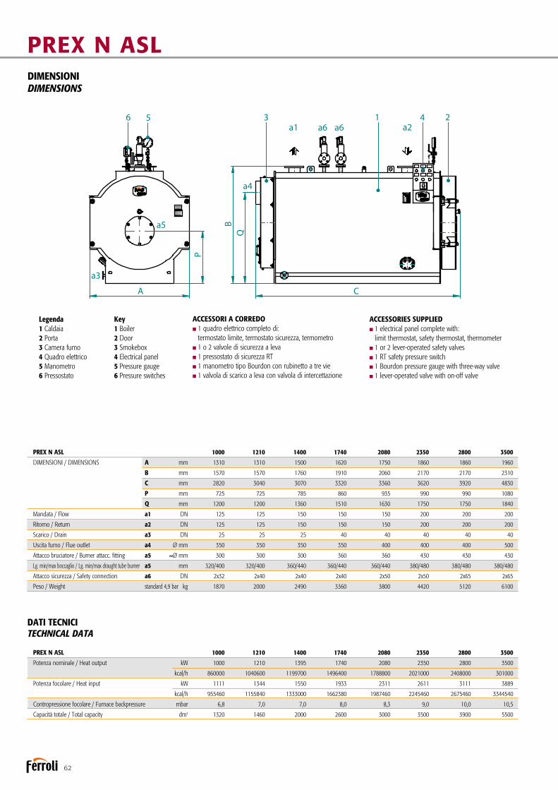
62
PREX N ASLDIMENSIONIDIMENSIONS
PREX N AS_ 160-3500 Pressione max esercizio* / Max working pressure* 4,9/ 12 barPressione prova / Hydraulic test pressure 8,57/ 21 bar Temperatura progetto / Design temperature 158/191,7 °C
Disegno N° 3936605/0Data ultima revisione 11/02/2011
Generatore d'acqua surriscaldata Superheated water generator
* Pressione max esercizio a richiesta / *Max working pressure on request 14,8 bar
a4
a5
a3
23 41
A C
QB
P
56a1 a6a6 a2
PREX N.pdf 1 19/05/14 10.35
PREX N ASL 1000 1210 1400 1740 2080 2350 2800 3500
DIMENSIONI / DIMENSIONS A mm 1310 1310 1500 1620 1750 1860 1860 1960
B mm 1570 1570 1760 1910 2060 2170 2170 2310
C mm 2820 3040 3070 3320 3360 3620 3920 4830
P mm 725 725 785 860 935 990 990 1080
Q mm 1200 1200 1360 1510 1630 1750 1750 1840
Mandata / Flow a1 DN 125 125 150 150 150 200 200 200
Ritorno / Return a2 DN 125 125 150 150 150 200 200 200
Scarico / Drain a3 DN 25 25 25 40 40 40 40 40
Uscita fumo / Flue outlet a4 Ø mm 350 350 350 350 400 400 400 500
Attacco bruciatore / Burner attacc. fitting a5 ů mm 300 300 300 360 360 430 430 430
Lg. min/max boccaglio / Lg. min/max draught tube burner a5 mm 320/400 320/400 360/440 360/440 360/440 380/480 380/480 380/480
Attacco sicurezza / Safety connection a6 DN 2x32 2x40 2x40 2x40 2x50 2x50 2x65 2x65
Peso / Weight standard 4,9 bar kg 1870 2000 2490 3360 3800 4420 5120 6100
DATI TECNICITECHNICAL DATA
PREX N ASL 1000 1210 1400 1740 2080 2350 2800 3500
Potenza nominale / Heat output kW 1000 1210 1395 1740 2080 2350 2800 3500
kcal/h 860000 1040600 1199700 1496400 1788800 2021000 2408000 301000
Potenza focolare / Heat input kW 1111 1344 1550 1933 2311 2611 3111 3889
kcal/h 955460 1155840 1333000 1662380 1987460 2245460 2675460 3344540
Contropressione focolare / Furnace backpressure mbar 6,8 7,0 7,0 8,0 8,3 9,0 10,0 10,5
Capacità totale / Total capacity dm3 1320 1460 2000 2600 3000 3500 3900 5500
Legenda1 Caldaia2 Porta3 Camera fumo4 Quadro elettrico5 Manometro6 Pressostato
Key1 Boiler2 Door3 Smokebox4 Electrical panel5 Pressure gauge6 Pressure switches
ACCESSORI A CORREDOn1 quadro elettrico completo di: termostato limite, termostato sicurezza, termometron1 o 2 valvole di sicurezza a levan1 pressostato di sicurezza RTn1 manometro tipo Bourdon con rubinetto a tre vien1 valvola di scarico a leva con valvola di intercettazione
ACCESSORIES SUPPLIEDn1 electrical panel complete with: limit thermostat, safety thermostat, thermometern1 or 2 lever-operated safety valvesn1 RT safety pressure switchn1 Bourdon pressure gauge with three-way valven1 lever-operated valve with on-off valve

63
ACCESSORI A RICHIESTA
nQuadro comandi con PLC per esigenze specifiche di comu-nicazione con BMS o sistemi di supervisione
nTronchetto porta strumenti in grado di accogliere tutta la strumentazione di regolazione e di sicurezza della caldaia, proponibile in diverse configurazioni
nEconomizzatore: è uno scambiatore di calore acqua-fumi che permette di ottenere un incremento del rendimento fino al 5%. La sua configurazione e la collocazione del medesimo sono eseguiti secondo le esigenze del Cliente.
nCollegamento economizzatore completo di prolungamen-to tubazione di ritorno, pompa di circolazione con valvole di intercettazione e collegamento meccanico all’economizzatore realizzato presso nostro stabilimento.
nSistema per l’esercizio in assenza di supervisione con-tinua fino a 24 ore.
nSistema per l’esercizio in assenza di supervisione con-tinua fino a 72 ore.
nBruciatore: marchio e tipologia secondo le indicazioni del cliente.nPiastra porta bruciatore perforata secondo le indicazioni
del cliente.nScala e passerella per accedere in sicurezza alla pedana cal-
pestabile sopra la caldaia.nCassa fumi posteriore completamente rivestita con materas-
sino in lana minerale ad alta densità.nAttacco camino verticale.nVaso di espansione pressurizzato.nSonde di minimo livello FAIL SAFE.nCertificazione “MODULO F” presso l’utilizzatore.n B.E.C.S. (Boiler Electronic Configurable System): il sistema
dicontrollo B.E.C.S. è costituito da un PLC dotato di interfaccia operatore Touch Panel a colori di elevate prestazioni. Tramite l’interfaccia è possibile supervisionare il funzionamento dell’in-sieme Caldaia-Bruciatore-Impianto.
ACCESSORIES AVAILABLE ON REQUEST
nControl panel with PLC for specific communication needs to BMS or supervision systems.
nPipe stub for instrument connection able to house all boiler control and safety instruments, available in different configurations.
nEconomiser: a water-flue gas heat exchanger that increases efficiency by up to 5%. Its configuration and position are defi-ned based on customer requirements.
nEconomiser connection complete with return pipe exten-sion, circulating pump with on-off valves and mechanical con-nection to the economiser performed directly at our facilities.
nSystem for up to 24 hours’ continuous unsupervised operation.
nSystem for up to 72 hours’ continuous unsupervised operation.
nBurner: brand and type chosen based on customer specifica-tions.
nPerforated burner plate based on customer specifications.nLadder and walkway for safe access to the walkable plat-
form on top of the boiler.nRear smokebox completely lined with high density mineral
wool insulation.nVertical flue connection.nPressurised expansion vessel.nFAIL SAFE minimum level probes.nB.E.C.S. (Boiler Electronic Configurable System): the B.E.C.S.
control system consists of a PLC fitted with high performance Touch Panel colour operator interface. The interface can be used to manage operation of the Boiler-Burner-Central Heating System.

64
PREX N ASH
Generatore termico a combustione pressurizzata ed elevata effi-cienza energetica. Predisposto per funzionare in abbinamento ad un bruciatore ad aria soffiata a combustibile liquido o gassoso. Focolare ad inversione di fiamma e camera di combustione con fondo bagnato e dimensionata in modo tale da assicurare bassi carichi termici. L’intera gamma è suddivisa in due configurazioni tra loro differenziate dalla pressione di esercizio.
nPressione standard di progetto: versione a 12 bar; versione 14,8 bar.nTemperatura di progetto insieme: 191,7°C (vers. 12 bar); 200°C (vers. 14,8 bar).nDi moderna concezione e ad alto rendimento, questi genera-
tori sono progettati e realizzati nel rispetto della Direttiva Europea 2014/68/UE (PED) e delle più recenti norme nazio-nali ed europee in materia di recipienti a pressione.
nLa saldatura piastra/fasciame a piena penetrazione ed i tubi da fumo sono prima accostati a mezzo mandrinatura e poi salda- ti alla piastra tubiera. nIl focolare è ampiamente dimensionato in diametro e lun-
ghezza così da consentire un carico termico contenuto. nI generatori PREX N ASH sono dotati di turbolatori in acciaio
inox posizionati all’interno dei tubi da fumo che impediscono il formarsi di uno strato limite stazionario sulla superficie dei medesimi, migliorando di conseguenza lo scambio termico.
Superheated water generator with pressurised combustion and high energy efficiency. Ready for operation in combination with a jet burner on liquid or gas fuel. Furnace with flame reversal and combustion chamber with cooled end plate sized to ensure low heating loads. The entire range is divided into two configu-rations that differ based on operating pressure.
nStandard design pressure: 12 bar version; 14.8 bar version.nAssembly temperature: 191.7°C (12 bar ver.); 200°C (14.8 bar vers.).nThese modern-concept and high-efficiency generators have
been designed and developed in compliance with European Directive 2014/68/UE (PED) and the most recent national and European standards on pressurised recipients.
nDeep penetration plate/plating welding, with the flues first enlar-ged using a pipe expander, then welded to the tube plate.
nThe furnace is amply sized in terms of diameter and length to allow limited heating loads.
nThe PREX N ASH generators are fitted with stainless steel turbulators positioned inside the flue to prevent formation of a stationary layer on the surface and consequently improve heat exchange.
Generatore d’acqua surriscaldata a tre giri di fumo di cui due in camera di combustioneSuperheated water generator with three flue passes, two in furnace

65
nSuitable insulation of the boiler body using high-density mineral wool protected by stainless steel plate limits heat loss to the surrounding environment.
nThe door is insulated on the inside with a suitable layer of refractory concrete and covers the entire heated surface of the tube plate.
nThe parts subject to pressure are all welded by qualified and IIS approved personnel, according to EN standards.
nFront door with reversible opening (right and left) and closing system with micrometric adjustment on the front of the boiler.
nThe water circuit can be inspected through a manhole at the top of the boiler and a hand opening ring at the bottom.nThe boiler drain can be located on either side (R or L).nMaintenance guaranteed by easy access to the furnace and the
tube bundle through the door and the removable smokebox.
CERTIFICATIONCE mark in accordance with the following directives Pressure Equipment (2014/68/UE)Low Voltage (2014/35/UE)Electromagnetic Compatibility (2014/30/UE)
nGrazie ad una adeguata coibentazione del corpo caldaia eseguita con uno strato di lana minerale ad alta densità, protet-to di lamierino inox, le dispersioni verso l’ambiente sono molto contenute.
nIl portellone è internamente rivestito con un adeguato spes-sore di cemento refrattario e copre, su tutta la sua estensione, la superficie riscaldata della piastra tubiera.
nLe saldature delle parti in pressione sono tutte eseguite da personale qualificato ed approvato IIS secondo norme EN.
nPortellone anteriore con apertura reversibile (destra e sini-stra) e sistema di chiusura e regolazione micrometrica sulla piastra frontale del generatore.
nL’ispezionabilità lato acqua è garantita mediante un passo uomo sul colmo caldaia e da un passa mano sulla parte inferiore.
nLo scarico caldaia è orientabile (DX o SX).nManutenzione garantita dalla facilità di accesso dal portello- ne al focolare e al fascio tubiero e dalla cassa fumi smontabile.
CERTIFICAZIONIMarcatura CE secondo le Direttive Apparecchi a pressione (2014/68/UE)Bassa Tensione (2014/35/UE) Compatibilità Elettromagnetica (2014/30/UE)
Isolamento portellone in acciaio refrattario
Refractory steel door insulation
Quadro elettrico
Electrical panel
Manometro
Pressure gauge
Passo uomo
ManholeRitorno
Return
Valvole di sicurezza
Safety valves
Mandata
Outlet
Pressostati di sicurezza
Safety pressure switches
Focolare a fondo bagnato a basso carico termico
Furnace with cooled end plate and low heating load
Sistema di chiusurae regolazione portellone
Door closing and adjustment system
Portellone con aperturareversibile dx e sx
Door with reversible opening, R and L

66
PREX N ASHDIMENSIONIDIMENSIONS
PREX N AS_ 160-3500 Pressione max esercizio* / Max working pressure* 4,9/ 12 barPressione prova / Hydraulic test pressure 8,57/ 21 bar Temperatura progetto / Design temperature 158/191,7 °C
Disegno N° 3936605/0Data ultima revisione 11/02/2011
Generatore d'acqua surriscaldata Superheated water generator
* Pressione max esercizio a richiesta / *Max working pressure on request 14,8 bar
a4
a5
a3
23 41
A C
QB
P
56a1 a6a6 a2
PREX N.pdf 1 19/05/14 10.35
PREX N ASH 160 280 410 560 700 1000 1210 1400 1740 2080 2350 2800 3500
DIMENSIONI / DIMENSIONS A mm 900 960 1060 1190 1190 1310 1310 1500 1620 1750 1860 1860 1960
B mm 1130 1190 1290 1420 1420 1570 1570 1760 1910 2060 2170 2170 2310
C mm 1740 2000 2190 2350 2540 2820 3040 3070 3320 3360 3620 3920 4830
P mm 580 610 660 630 630 725 725 785 860 935 990 990 1080
Q mm 840 890 935 1070 1070 1200 1200 1360 1510 1630 1750 1750 1840
Mandata / Flow a1 DN 65 65 80 100 100 125 125 150 150 150 200 200 200
Ritorno / Return a2 DN 65 65 80 100 100 125 125 150 150 150 200 200 200
Scarico / Drain a3 DN 25 25 25 25 25 25 25 25 40 40 40 40 40
Uscita fumo / Flue outlet a4 Ø mm 200 200 250 250 250 350 350 350 350 400 400 400 500
Attacco bruciatore / Burner attacc. fitting a5 ů mm 220 240 240 270 270 300 300 300 360 360 430 430 430
Lg. min/max boccaglio / Lg. min/max draught tube burner a5 mm 300/380 320/400 320/400 320/400 320/400 320/400 320/400 360/440 360/440 360/440 380/480 380/480 380/480
Attacco sicurezza / Safety connection a6 DN 1x25 1x25 1x25 2x25 2x25 2x25 2x25 2x25 2x25 2x25 2x32 2x32 2x32
Peso / Weight 12 bar kg 820 920 1200 1540 1690 2300 2660 3150 4200 4750 5500 6400 7800
DATI TECNICITECHNICAL DATA
PREX N ASH 160 280 410 560 700 1000 1210 1400 1740 2080 2350 2800 3500
Potenza nominale / Heat output kW 160 280 410 560 700 1000 1210 1395 1740 2080 2350 2800 3500
kcal/h 137600 240800 352600 481600 602000 860000 1040600 1199700 1496400 1788800 2021000 2408000 301000
Potenza focolare / Heat input kW 178 311 456 622 778 1111 1344 1550 1933 2311 2611 3111 3889
kcal/h 153080 267460 392160 534920 669080 955460 1155840 1333000 1662380 1987460 2245460 2675460 3344540
Contropressione focolare / Furnace backpressure mbar 2,7 3,5 4,5 5,0 6,0 6,8 7,0 7,0 8,0 8,3 9,0 10,0 10,5
Capacità totale / Total capacity dm3 400 520 600 900 1040 1320 1460 2000 2600 3000 3500 3900 5500
Legenda1 Caldaia2 Porta3 Camera fumo4 Quadro elettrico5 Manometro6 Pressostato
Key1 Boiler2 Door3 Smokebox4 Electrical panel5 Pressure gauge6 Pressure switches
ACCESSORI A CORREDOn1 quadro elettrico completo di: termostato limite, termostato sicurezza, termometron1 o 2 valvole di sicurezza a mollan1 pressostato di sicurezza RTn1 manometro tipo Bourdon con rubinetto a tre vien1 valvola di scarico a leva con valvola di intercettazione
ACCESSORIES SUPPLIEDn1 electrical panel complete with: limit thermostat, safety thermostat, thermometern1 or 2 spring-loaded safety valvesn1 RT safety pressure switchn1 Bourdon pressure gauge with three-way valven1 lever-operated valve with on-off valve

67
ACCESSORI A RICHIESTA
nQuadro comandi con PLC per esigenze specifiche di comu-nicazione con BMS o sistemi di supervisione.
nTronchetto porta strumenti in grado di accogliere tutta la strumentazione di regolazione e di sicurezza della caldaia, proponibile in diverse configurazioni.
nEconomizzatore: è uno scambiatore di calore acqua-fumi che permette di ottenere un incremento del rendimento fino al 5%. La sua configurazione e la collocazione del medesimo sono eseguiti secondo le esigenze del Cliente.
nCollegamento economizzatore completo di prolungamen-to tubazione di ritorno, pompa di circolazione con valvole di intercettazione e collegamento meccanico all’economizzatore realizzato presso nostro stabilimento.
nSistema per l’esercizio in assenza di supervisione con-tinua fino a 24 ore.
nSistema per l’esercizio in assenza di supervisione con-tinua fino a 72 ore.
nBruciatore: marchio e tipologia secondo le indicazioni del cliente.nPiastra porta bruciatore perforata secondo le indicazioni
del cliente. nScala e passerella per accedere in sicurezza alla pedana cal- pestabile sopra la caldaia.nCassa fumi posteriore completamente rivestita con mate- rassino in lana minerale ad alta densità.nAttacco camino verticale.nVaso di espansione pressurizzato.nSonde di minimo livello FAIL SAFE.nCertificazione “MODULO F” presso l’utilizzatore.n B.E.C.S. (Boiler Electronic Configurable System): il sistema
dicontrollo B.E.C.S. è costituito da un PLC dotato di interfaccia operatore Touch Panel a colori di elevate prestazioni. Tramite l’interfaccia è possibile supervisionare il funzionamento dell’in-sieme Caldaia-Bruciatore-Impianto.
ACCESSORIES AVAILABLE ON REQUEST
nC ontrol panel with PLC for specific communication needs to BMS or supervision systems.
nPipe stub for instrument connection able to house all boiler control and safety instruments, available in different configurations.
nEconomiser: a water-flue gas heat exchanger that increases efficiency by up to 5%. Its configuration and position are defi-ned based on customer requirements.
nEconomiser connection complete with return pipe exten-sion, circulating pump with on-off valves and mechanical con-nection to the economiser performed directly at our facilities.
nSystem for up to 24 hours’ continuous unsupervised operation.
nSystem for up to 72 hours’ continuous unsupervised operation.
nBurner: brand and type chosen based on customer specifica-tions.
nPerforated burner plate based on customer specifications.nLadder and walkway for safe access to the walkable plat-
form on top of the boiler.nRear smokebox completely lined with high density mineral
wool insulation.nVertical flue connection.nPressurised expansion vessel.nFAIL SAFE minimum level probes.nB.E.C.S. (Boiler Electronic Configurable System): the B.E.C.S.
control system consists of a PLC fitted with high performance Touch Panel colour operator interface. The interface can be used to manage operation of the Boiler-Burner-Central Heating System.

68
PREXTHERM T3G F ASL
Generatore termico a combustione pressurizzata ed elevata effi-cienza energetica a tre giri di fumo. Predisposto per funzionare in abbinamento ad un bruciatore ad aria soffiata a combustibile liquido o gassoso. La geometria della camera di combustione a fondo bagnato, ed il generoso dimensionamento, garantiscono un basso carico termico e la possibilità, in abbinamento ad un bruciatore idoneo, di realizzare una combustione a basse emis-sioni di NOx. Gamma composta da 14 modelli con potenze nominali da 1.200 a 9.000 kW.nPressione massima di esercizio 6 bar o 8 barnTemperatura progetto insieme: 140°CnDi moderna concezione e ad alto rendimento, questi gene-
ratori sono progettati e realizzati nel rispetto della Direttiva Europea 2014/68/UE (PED) e delle più recenti norme nazio-nali ed europee in materia di recipienti a pressione.
nCamera di combustione costituita da un grande focolare, rinforza-to con giunti omega, a garanzia di un utilizzo a bassi carichi termici con camera di inversione completamente raffreddata ad acqua.
nFascio tubiero sul secondo e terzo giro fumi, ad elevata superficie di scambio.
Superheated water generator with pressurised combustion and high energy efficiency, three flue gas passes. Ready for opera-tion in combination with a jet burner on liquid or gas fuel.The arrangement and generous sizing of the combustion cham-ber with cooled end plate guarantee a low heating load and the possibility, when combined with a suitable burner, to ensure combustion with low NOx emissions.Range consisting of 14 models with rated outputs from 1,200 to 9,000 kW.
nMaximum operating pressure 6 bars or 8 barsnAssembly temperature: 140°CnThese modern-concept and high-efficiency generators have
been designed and developed in compliance with European Directive 2014/68/UE (PED) and the most recent national and European standards on pressurised recipients.
nCombustion chamber consisting of a large furnace reinfor-ced with omega joints to guarantee operation at low heating loads, with completely water-cooled reversing chamber.
nTube bundle on the second and third flue gas pass, with high heat exchange surface.
Caldaia d’acqua surriscaldata a tre giri effettivi di fumoSuperheated water boiler with three effective flue passes

69
nSuitable insulation of the boiler body using high-density mineral wool protected by stainless steel plate limits heat loss to the surrounding environment.
nThe door is insulated on the inside with a suitable layer of refractory concrete and covers the entire heated surface of the tube plate.
nFront door with reversible opening (right and left) and innovative closing system with micrometric adjustment on the boiler front plate.
nThe parts subject to pressure are all welded by qualified and IIS approved personnel, according to EN standards.
nThe water circuit can be inspected through a manhole at the top of the boiler and a hand opening ring at the bottom.
nMaintenance guaranteed by easy access to the furnace andthe tube bundle through the door, the removable smokebox and the inspection door on the boiler body.
CERTIFICATIONCE mark in accordance with the following directives Pressure Equipment (2014/68/UE)Low Voltage (2014/35/UE)Electromagnetic Compatibility (2014/30/UE)
nGrazie ad una adeguata coibentazione del corpo caldaia eseguita con uno strato di lana minerale ad alta densità, protet-to di lamierino inox, le dispersioni verso l’ambiente sono molto contenute.
nIl portellone è internamente rivestito con un adeguato spes- sore di cemento refrattario e copre, su tutta la sua estensione, la superficie riscaldata della piastra tubiera.nPortellone anteriore con apertura reversibile (destra e
sinistra) ed innovativo sistema di chiusura e regolazione micro-metrica sulla piastra frontale del generatore.
nLe saldature delle parti in pressione sono tutte eseguite da personale qualificato ed approvato IIS secondo norme EN.
nL’ispezionabilità lato acqua è garantita mediante un passo uomo sul colmo caldaia e da un passa mano sulla parte inferiore.
nManutenzione garantita dalla facilità di accesso dal portellone al focolare ed al fascio tubiero, dalla cassa fumi smontabile e dalla portina di ispezione sul corpo caldaia.
CERTIFICAZIONIMarcatura CE secondo le Direttive Apparecchi a pressione (2014/68/UE)Bassa Tensione (2014/35/UE) Compatibilità Elettromagnetica (2014/30/UE)
Corpo caldaia interamente rivestito con materassino in lana minerale
Boiler body completely lined with rock wool insulation
Isolamento portellone in cemento refrattario
Door insulated with refractory concrete
Andata impianto
Central heating flow outlet
Passo uomo
Manhole
Ritorno impianto
Central heatingreturn inlet
Attacco di sicurezza
Safety connection
Camera di inversione fumi a fondo bagnato
Reversing combustion chamber with cooled end plate
Focolare a basso carico termicoe rinforzato con giunti omega
Furnace with low heating load and reinforced with omega jointsPortellone con apertura
reversibile dx e sx
Door with reversible opening, R and L

70
PREXTHERM T3G F ASLDIMENSIONIDIMENSIONS
PREXTHERM T3G F ASL 1000÷9000 Pressione max esercizio * Pressione prova Temperatura progetto
Disegno / Drawing Nr. 3936610/0Generatore d'acqua caldaHot water generator
Max working pressure **Hydraulic test pressureDesign temperature
6 bar9 bar145 °C
rev. 14-02-2011
KWdm
KWPotenza utile - Heat output
Capacità totale caldaia - Boiler total capacityPotenza focolare - Heat input
1200120012972200
1400140015132450
1750175019023250
2000200021623650
2300230025004800
2800280030275250
3400340037005500
4000400043547250
4600460050007600
PREXTHERM T3G 52005200565310500
60006000652212100
700070007609
13500
800080008697
17150
900090009783
18200Perdite carico lato acqua - Loss pressure water side t 15 °C 35 52 45 50 70 65 90 130 170 140 120 150 210 230m barPerdite carico lato fumi - Pressure drop flue gas side 4,5 6,3 5,5 7,4 4 5,2 6,1 5,4 7,5 8,2 6,1 8,4 8,2 8,5m barPortata fumi * - Flue gas flow-rate * 2078 2424 3047 3463 3982 4848 5887 6926 7964 9003 9787 11418 13049 14680kg/hPressione max esercizio ** - Max working pressure ** 6 6 6 6 6 6 6 6 6 6 6 6 6 6bar
10 bar6 bar kg
kg3750 3900 5000 5250 5400 5950 7200 8700 9500 11900 13800 14700 17500 197004150 4400 5550 6000 6300 6700 8000 9600 10800 12700 15000 16600 20500 21800
Peso a secco - Dry weight
T1
T3T4T5
ABC
DN125 DN125 DN150 DN150 DN150 DN200 DN200 DN200 DN200 DN250 DN250 DN250 DN250 DN250
DN40 DN40 DN40 DN40 DN50 DN50 DN50 DN65 DN65 DN65 DN65 DN80 DN80 DN80DN40 DN40 DN40 DN40 DN40 DN40 DN40 DN40 DN40 DN40 DN40 DN40 DN40 DN40400 400 450 450 450 500 600 600 700 700 700 800 900Ø mm 500
T2 DN125 DN125 DN150 DN150 DN150 DN200 DN200 DN200 DN200 DN250 DN250 DN250 DN250 DN250mandata - flowritorno - return
sicurezze - safety
uscita fumo - flue outletscarico - drain
attacco bruciatore - burner attac. fittinglg. min/max boccaglio - lg. min/max draugt tube burner
T6Ø mmAT
TACC
HI -
FITTIN
G
220 220 220 240 240 240 300 360 360 360 430 430 430270280/380 280/380 280/380 280/380 280/380 280/380 310/410 310/410 390/490 390/490 390/490 390/490 390/490280/380
DE
DIMENSIONI - DIMENSIONS
1560 1560 1760 1760 2010 2010 2220 2220 2500 2500 2500 2710 271020101870 1870 2090 2090 2280 2280 2590 2590 2780 2780 2780 3040 304022803280 3530 3680 3930 3940 4260 4930 5180 5730 6050 6530 6990 72904510790 790 875 875 890 890 1070 1070 1105 1105 1105 1220 12208901350 1350 1550 1550 1650 1650 1900 1900 2140 2140 2140 2140 21401650
Legenda 1 Caldaia 2 Porta 3 Camera Fumo 4 Quadro elettrico
Key 1 Boiler 2 Door 3 Smokebox 4 Electrical panel
* Combustibile gasolio: CO² = 13% - Combustibile gas: CO² = 10%* Oil fuel: CO² = 13% - Gas fuel: CO² = 10%
standardoptional
** Pressione max esercizio a richiesta:** Max working pressure on request: 8 bar / 10 bar
* Combustibile gasolio: CO2 = 13% - combustibile gas: CO2 = 10%* Oil fuel: CO2 = 13% - Gas fuel: CO2 = 10%
PREXTHERM T 3G F ASL 1200 1400 1750 2000 2300 2800 3400 4000 4600 5200 6000 7000 8000 9000
DIMENSIONI / DIMENSIONS A mm 1560 1560 1760 1760 2010 2010 2010 2220 2220 2500 2500 2500 2710 2710
B mm 1870 1870 2090 2090 2280 2280 2280 2590 2590 2780 2780 2780 3040 3040
C mm 3280 3530 3680 3930 3940 4260 4510 4930 5180 5730 6050 6530 6990 7290
D mm 790 790 875 875 890 890 890 1070 1070 1105 1105 1105 1220 1220
E mm 1350 1350 1550 1550 1650 1650 1650 1900 1900 2140 2140 2140 2140 2140
ATTACCHI / FITTINGS
Mandata / Flow T1 DN 125 125 150 150 150 200 200 200 200 250 250 250 250 250
Ritorno / Return T2 DN 125 125 150 150 150 200 200 200 200 250 250 250 250 250
Sicurezze / Safety T3 DN 40 40 40 40 50 50 50 65 65 65 65 80 80 80
Scarico / Drain T4 DN 40 40 40 40 40 40 40 40 40 40 40 40 40 40
Uscita fumo / Flue outlet T5 Ø mm 400 400 450 450 450 500 500 600 600 700 700 700 800 900
Attacco bruciatore / Burner attacc. fitting T6
Ø mm 350 350 360 360 375 375 375 430 430 475 475 475 495 495
Lg. min/max boccaglio / Lg. min/max draught tube burner 280/380 280/380 280/380 280/380 280/380 280/380 280/380 310/410 310/410 390/490 390/490 390/490 390/490 390/490
Peso a secco / Dry weight standard 6 bar kg 3750 3900 5000 5250 5400 5950 7200 8700 9500 11900 13800 14700 17500 19700
DATI TECNICITECHNICAL DATA
PREXTHERM T 3G F ASL 1200 1400 1750 2000 2300 2800 3400 4000 4600 5200 6000 7000 8000 9000
Potenza utile / Heat output kW 1200 1400 1750 2000 2300 2800 3400 4000 4600 5200 6000 7000 8000 9000
Potenza focolare / Heat input kW 1297 1513 1902 2162 2500 3027 3700 4354 5000 5653 6522 7609 8697 9783
Capacità totale caldaia / Boiler total capacity dm3 2200 2450 3250 3650 4800 5250 5500 7250 7600 10500 12100 13500 17150 18200
Perdite di carico lato acqua ∆t 15°C mbar 35 52 45 50 70 65 90 130 170 140 120 150 210 230
Loss pressure water side
Perdite di carico lato fumi / Press. drop flue gas side mbar 4,5 6,3 5,5 7,4 4 5,2 6,1 5,4 7,5 8,2 6,1 8,4 8,2 8,5
Portata fumi* / Flue gas flow-rate* kg/h 2078 2424 3047 3463 3982 4848 5887 6926 7964 9003 9787 11418 13049 14680
Pressione max esercizio** / Max working pressure** bar 6 6 6 6 6 6 6 6 6 6 6 6 6 6
Legenda1 Caldaia2 Porta3 Camera fumo4 Quadro elettrico
Key1 Boiler2 Door3 Smokebox4 Electrical panel
ACCESSORI A CORREDOn1 quadro elettrico completo di: termostato limite, termostato sicurezza, termometron1 o 2 valvole di sicurezza a mollan1 pressostato di sicurezza RTn1 manometro tipo Bourdon con rubinetto a tre vien1 valvola di scarico a leva con valvola di intercettazione
ACCESSORIES SUPPLIEDn1 electrical panel complete with: limit thermostat, safety thermostat, thermometern1 or 2 lever-operated safety valvesn1 RT safety pressure switchn1 Bourdon pressure gauge with three-way valven1 lever-operated valve with on-off valve

71
ACCESSORI A RICHIESTA
nQuadro comandi con PLC per esigenze specifiche di comu- nicazione con BMS o sistemi di supervisione.nTronchetto porta strumenti in grado di accogliere tutta la
strumentazione di regolazione e di sicurezza della caldaia, proponibile in diverse configurazioni.
nEconomizzatore: è uno scambiatore di calore acqua-fumi che permette di ottenere un incremento del rendimento fino al 5%. La sua configurazione e la collocazione del medesimo sono eseguiti secondo le esigenze del Cliente.
nCollegamento economizzatore completo di prolungamen-to tubazione di ritorno, pompa di circolazione con valvole di intercettazione e collegamento meccanico all’economizzatore realizzato presso nostro stabilimento.
nSistema per l’esercizio in assenza di supervisione con-tinua fino a 24 ore.
nSistema per l’esercizio in assenza di supervisione con-tinua fino a 72 ore.
nBruciatore: marchio e tipologia secondo le indicazioni del cliente.
nPiastra porta bruciatore perforata secondo le indicazioni del cliente.
nScala e passerella per accedere in sicurezza alla pedana cal-pestabile sopra la caldaia.
nCassa fumi posteriore completamente rivestita con materas-sino in lana minerale ad alta densità.
nAttacco camino verticale.nVaso di espansione pressurizzato.nSonde di minimo livello FAIL SAFE.nCertificazione “MODULO F” presso l’utilizzatore.n B.E.C.S. (Boiler Electronic Configurable System): il sistema
dicontrollo B.E.C.S. è costituito da un PLC dotato di interfaccia operatore Touch Panel a colori di elevate prestazioni. Tramite l’interfaccia è possibile supervisionare il funzionamento dell’in-sieme Caldaia-Bruciatore-Impianto.
ACCESSORIES AVAILABLE ON REQUEST
nControl panel with PLC for specific communication needs to BMS or supervision systems.
nPipe stub for instrument connection able to house all boi-ler control and safety instruments, available in different con-figurations.
nEconomiser: a water-flue gas heat exchanger that increasesefficiency by up to 5%. Its configuration and position are defined based on customer requirements.
nEconomiser connection complete with return pipe exten-sion, circulating pump with on-off valves and mechanical con-nection to the economiser performed directly at our facilities.
nSystem for up to 24 hours’ continuous unsupervised operation.
nSystem for up to 72 hours’ continuous unsupervised operation.
nBurner: brand and type chosen based on customer specifi-cations.
nPerforated burner plate based on customer specifications.nLadder and walkway for safe access to the walkable plat-
form on top of the boiler.nRear smokebox completely lined with high density mineral
wool insulation.nVertical flue connection.nPressurised expansion vessel.nFAIL SAFE minimum level probes.nB.E.C.S. (Boiler Electronic Configurable System): the B.E.C.S.
control system consists of a PLC fitted with high performance Touch Panel colour operator interface. The interface can be used to manage operation of the Boiler-Burner-Central Heating System.

72
PREXTHERM T3G N ASL
Generatore termico a combustione pressurizzata ed elevata effi-cienza energetica a tre giri di fumo. Predisposto per funzionare in abbinamento ad un bruciatore ad aria soffiata a combustibile liquido o gassoso. La geometria della camera di combustione a fondo bagnato, ed il generoso dimensionamento, garantiscono un basso carico termico e la possibilità, in abbinamento ad un bruciatore idoneo, di realizzare una combustione a basse emis-sioni di NOx. Gamma composta da 7 modelli, con potenze utili da 6.800 kW a 15.000 kW.nPressione standard di progetto: 6 o 8 bar.nTemperatura di progetto insieme: 140°C.nDi moderna concezione e ad alto rendimento, questi gene-
ratori sono progettati e realizzati nel rispetto della Direttiva Europea 2014/68/UE (PED) e delle più recenti norme nazio-nali ed europee in materia di recipienti a pressione.
nCamera di combustione costituita da un grande focolare, rinforza-to con giunti omega, a garanzia di un utilizzo a bassi carichi termici con camera di inversione completamente raffreddata ad acqua.
nFascio tubiero sul secondo e terzo giro fumi, ad elevata superficie di scambio.
Superheated water generator with pressurised combustion and high energy efficiency, three flue gas passes. Ready for opera-tion in combination with a jet burner on liquid or gas fuel.The arrangement and generous sizing of the combustion cham-ber with cooled end plate guarantee a low heating load and the possibility, when combined with a suitable burner, to ensure combustion with low NOx emissions.Range consisting of 7 models, with useful heat outputs from 6,800 kW to 15,000 kW.
nStandard design pressure: 6 or 8 bar.nAssembly temperature: 140°C.nThese modern-concept and high-efficiency generators have
been designed and developed in compliance with European Directive 2014/68/UE (PED) and the most recent national and European standards on pressurised recipients.
nCombustion chamber consisting of a large furnace reinfor-ced with omega joints to guarantee operation at low heating loads, with completely water-cooled reversing chamber.
nTube bundle on the second and third flue gas pass, with high heat exchange surface.
Generatore d’acqua surriscaldata a tre giri effettivi di fumoSuperheated water generator with three flue passes

73
nSuitable insulation of the boiler body using high-density mineral wool protected by stainless steel plate limits heat loss to the surrounding environment.
nLarge inspection doors both on the front, for flue gas reversal from the second to third pass, and at the rear for the smokebox.
nThe water circuit can be inspected through a manhole at the top of the boiler and a hand opening ring at the bottom.nRear manhole for inspecting the furnace.nThe parts subject to pressure are all welded by qualified and
IIS approved personnel, according to EN standards.nRear smokebox completely lined with high density mineral
wool insulation.
CERTIFICATIONCE mark in accordance with the following directives Pressure Equipment (2014/68/UE)Low Voltage (2014/35/UE)Electromagnetic Compatibility (2014/30/UE)
nGrazie ad una adeguata coibentazione del corpo caldaia eseguita con uno strato di lana minerale ad alta densità, le dispersioni verso l’ambiente sono molto contenute.
nGrandi portelli di ispezione sia nella parte anteriore, di inversione dei fumi dal secondo al terzo giro, che in quella posteriore di raccolta fumi.
nL’ispezionabilità lato acqua è garantita mediante un passo uomo sul colmo caldaia e da un passa mano sulla parte inferiore.
nPasso uomo posteriore per ispezione del focolare.nLe saldature delle parti in pressione sono tutte eseguite da
per-sonale qualificato ed approvato IIS secondo norme EN. nCassa fumi posteriore completamente rivestita con mate-
rassino in lana minerale ad alta densità.
CERTIFICAZIONIMarcatura CE secondo le Direttive Apparecchi a pressione (2014/68/UE)Bassa Tensione (2014/35/UE) Compatibilità Elettromagnetica (2014/30/UE)
Corpo caldaia interamente rivestito con materassino in lana minerale
Boiler body completely linedwith rock wool insulation
Ampi portelli di chiusura e ispezione passaggio fumi
Large closing and flue gasinspection doors
Andata impianto
Central heating flow outlet
Passo uomo
Manhole
Ritorno impianto
Central heating return inlet
Attacco di sicurezza
Safety connection
Camera di inversione fumi a fondo bagnato
Reversing combustion chamber with cooled end plate
Focolare a basso carico termicoe rinforzato con giunti omega
Furnace with low heating load and reinforced with omega joints

74
* Combustibile gasolio: CO2 = 13% - combustibile gas: CO2 = 10%* Oil fuel: CO2 = 13% - Gas fuel: CO2 = 10%** Dimensioni superiori: verifica fattibilità su richiesta** On request we evaluate the feasibility for higher powers
PREXTHERM T3G N ASLDIMENSIONIDIMENSIONS
PREXTHERM T3G N ASL 6000÷19500Disegno / Drawing Nr. 3936626/0Generatore d'acqua surriscaldata
Superheated water generator rev. 24-02-2011
KWdm
KWPotenza utile - Heat output
Capacità totale caldaia - Boiler total capacityPotenza focolare - Heat input
PREXTHERM T3G 195001950021197
---Perdite carico lato acqua - Loss pressure water side t 15 °C ---m barPerdite carico lato fumi - Pressure drop flue gas side ---m barPortata fumi * - Flue gas flow-rate * ---kg/hPressione max esercizio ** - Max working pressure ** 6bar
10 bar6 bar kg
kg------
Peso a secco - Dry weight
T1
T3T4T5ABC
---
---------Ø mm
T2 ---mandata - flowritorno - return
sicurezze - safety
uscita fumo - flue outletscarico - drain
DE
DIMENSIONI - DIMENSIONS
---------------
* Combustibile gasolio: CO² = 13% - Combustibile gas: CO² = 10%* Oil fuel: CO² = 13% - Gas fuel: CO² = 10%
standardoptional
Pressione max esercizio **Pressione provaTemperatura progetto
Max working pressure **Hydraulic test pressureDesign temperature
6 bar9 bar145 °C
Legenda 1 Caldaia 2 Porta 3 Camera Fumo 4 Quadro elettrico
Key 1 Boiler 2 Door 3 Smokebox 4 Electrical panel
175001750019023
------------6---------
---------
---
---------------
150001500016305
------------6---------
---------
---
---------------
12000120001304423000
2308,9
179506
2600028000DN300
DN80DN40900
DN300
28603200786012402860
10000100001087021600
1808,7
163116
2300025000DN300
DN100DN40900
DN300
27103040729012202140
900090009783186002308,5
146806
1970021800DN250
DN80DN40900
DN250
27103040729012202140
800080008697
171502108,2
130496
1750020500DN250
DN80DN40800
DN250
27103040699012202140
70007000760913500
1508,4
114186
1470016600DN250
DN80DN40700
DN250
25002780653011052140
600060006522121001206,1
97876
1380015000DN250
DN65DN40700
DN250
25002780605011052140
** Pressione max esercizio a richiesta:** Max working pressure on request: 8 bar / 10 bar
ATTA
CCHI
-FIT
TING
PREXTHERM T 3G N ASL 6000 7000 8000 9000 10000 12000 15000
DIMENSIONI / DIMENSIONS A mm 2500 2500 2710 2710 2710 2860 3260
B mm 2780 2780 3040 3040 3040 3200 3700
C mm 6050 6530 6990 7290 7290 7860 8640
D mm 1105 1105 1220 1220 1220 1240 1382
E mm 2140 2140 2140 2140 2140 2860 2800
ATTACCHI / FITTINGS
Mandata / Flow T1 DN 250 250 250 250 300 300 350
Ritorno / Return T2 DN 250 250 250 250 300 300 350
Sicurezze / Safety T3 DN 65 80 80 80 100 80 100
Scarico / Drain T4 DN 40 40 40 40 40 40 65
Uscita fumo / Flue outlet T5 Ø mm 700 700 800 900 900 900 1000
Peso a secco / Dry weight standard 6 bar kg 13800 14700 17500 19700 23000 26000 33000
Legenda1 Caldaia2 Porta3 Camera fumo4 Quadro elettrico
Key1 Boiler2 Door3 Smokebox4 Electrical panel
ACCESSORI A CORREDOn1 quadro elettrico completo di: termostato limite, termostato sicurezza, termometron1 o 2 valvole di sicurezza a levan1 pressostato di sicurezza RTn1 manometro tipo Bourdon con rubinetto a tre vien1 valvola di scarico a leva con valvola di intercettazione
ACCESSORIES SUPPLIEDn1 electrical panel complete with: limit thermostat, safety thermostat, thermometern1 or 2 lever-operated safety valvesn1 RT safety pressure switchn1 Bourdon pressure gauge with three-way valven1 lever-operated valve with on-off valve
DATI TECNICITECHNICAL DATA
PREXTHERM T 3G N ASL 6000 7000 8000 9000 10000 12000 15000
Potenza utile / Heat output kW 6000 7000 8000 9000 10000 12000 15000
Potenza focolare / Heat input kW 6522 7609 8697 9783 10870 13044 16305
Capacità totale caldaia / Boiler total capacity dm3 12100 13500 17150 18600 21600 23000 31600
Perdite di carico lato acqua ∆t 15°C mbar 120 150 210 230 180 230 250
Loss pressure water side
Perdite di carico lato fumi / Press. drop flue gas side mbar 6,1 8,4 8,2 8,5 8,7 8,9 11,5
Portata fumi* / Flue gas flow-rate* kg/h 9787 11418 13049 14680 16311 17950 23500
Pressione max esercizio** / Max working pressure** bar 6 6 6 6 6 6 6
**
**

75
ACCESSORI A RICHIESTA
nQuadro comandi con PLC per esigenze specifiche di comu- nicazione con BMS o sistemi di supervisione.nTronchetto porta strumenti in grado di accogliere tutta la
strumentazione di regolazione e di sicurezza della caldaia, pro-ponibile in diverse configurazioni.
nEconomizzatore: è uno scambiatore di calore acqua-fumi chepermette di ottenere un incremento del rendimento fino al 5%. La sua configurazione e la collocazione del medesimo sono eseguiti secondo le esigenze del Cliente.
nCollegamento economizzatore completo di prolungamen-to tubazione di ritorno, pompa di circolazione con valvole di intercettazione e collegamento meccanico all’economizzatore realizzato presso nostro stabilimento.
nSistema per l’esercizio in assenza di supervisione con-tinua fino a 24 ore.
nSistema per l’esercizio in assenza di supervisione con-tinua fino a 72 ore.
nBruciatore: marchio e tipologia secondo le indicazioni del cliente.nScala e passerella per accedere in sicurezza alla pedana cal- pestabile sopra la caldaia.nAttacco camino verticale.nVaso di espansione pressurizzato.nSonde di minimo livello FAIL SAFE.nCertificazione “MODULO F” presso l’utilizzatore.n B.E.C.S. (Boiler Electronic Configurable System): il sistema di
controllo B.E.C.S. è costituito da un PLC dotato di interfaccia operatore Touch Panel a colori di elevate prestazioni. Tramite l’interfaccia è possibile supervisionare il funzionamento dell’in-sieme Caldaia-Bruciatore-Impianto.
ACCESSORIES AVAILABLE ON REQUEST
nControl panel with PLC for specific communication needs to BMS or supervision systems.nPipe stub for instrument connection able to house all boi
ler control and safety instruments, available in different con-figurations.
nEconomiser: a water-flue gas heat exchanger that increases efficiency by up to 5%. Its configuration and position are defined based on customer requirements.
nEconomiser connection complete with return pipe exten-sion, circulating pump with on-off valves and mechanical con-nection to the economiser performed directly at our facilities.
nSystem for up to 24 hours’ continuous unsupervised operation.
nSystem for up to 72 hours’ continuous unsupervised operation.
nBurner: brand and type chosen based on customer specifi-cations.
nLadder and walkway for safe access to the walkable plat-form on top of the boiler.
nVertical flue connection.nPressurised expansion vessel.nFAIL SAFE minimum level probes.nB.E.C.S. (Boiler Electronic Configurable System): the B.E.C.S.
control system consists of a PLC fitted with high performance Touch Panel colour operator interface. The interface can be used to manage operation of the Boiler-Burner-Central Heating System.

76
Caldaia d’acqua surriscaldata a tre giri effettivi di fumoSuperheated water generator with three flue passes
PREXTHERM T3G F ASH
Generatore termico a combustione pressurizzata ed elevata effi-cienza energetica a tre giri di fumo. Predisposto per funzionare in abbinamento ad un bruciatore ad aria soffiata a combustibile liquido o gassoso. La geometria della camera di combustione a fondo bagnato, ed il generoso dimensionamento, garantiscono un basso carico termico e la possibilità, in abbinamento ad un bruciatore idoneo, di realizzare una combustione a basse emis-sioni di NOx. Gamma composta da 14 modelli con potenze nominali da 1.200 a 9.000 kW.
nDi moderna concezione e ad alto rendimento, questi genera-tori sono progettati e realizzati nel rispetto della Direttiva Europea 2014/68/UE (PED) e delle più recenti norme nazio-nali ed europee in materia di recipienti a pressione.
nPressione massima di esercizio 12 bar o 15 bar; a richiesta pressioni superiori.
nTemperatura di progetto insieme: 191,7°C (vers. 12 bar); 200°C (vers. 15 bar).nCamera di combustione costituita da un grande focolare, rinforza-
to con giunti omega, a garanzia di un utilizzo a bassi carichi termici con camera di inversione completamente raffreddata ad acqua.
Superheated water generator with pressurised combustion and high energy efficiency, three flue gas passes. Ready for opera-tion in combination with a jet burner on liquid or gas fuel. The arrangement and generous sizing of the combustion chamber with cooled end plate guarantee a low heating load and the possibility, when combined with a suitable burner, to ensure combustion with low NOx emissions.Range consisting of 14 models with rated outputs from 1,200 to 9,000 kW.
nThese modern-concept and high-efficiency generators have been designed and developed in compliance with European Directive 2014/68/UE (PED) and the most recent national and European standards on pressurised recipients.
nMaximum operating pressure 12 bars or 15 bars; higher pressures on request.
nAssembly temperature: 191.7°C (12 bar ver.); 200°C (15 bar vers.).nCombustion chamber consisting of a large furnace reinfor-
ced with omega joints to guarantee operation at low heating loads, with completely water-cooled reversing chamber.
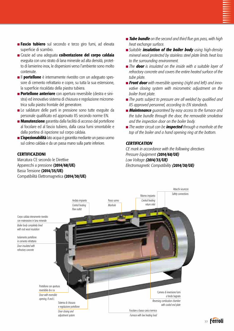
77
nTube bundle on the second and third flue gas pass, with high heat exchange surface.nSuitable insulation of the boiler body using high-density
mineral wool protected by stainless steel plate limits heat loss to the surrounding environment.
nThe door is insulated on the inside with a suitable layer of refractory concrete and covers the entire heated surface of the tube plate.
nFront door with reversible opening (right and left) and inno-vative closing system with micrometric adjustment on the boiler front plate.
nThe parts subject to pressure are all welded by qualified and IIS approved personnel, according to EN standards.
nMaintenance guaranteed by easy access to the furnace and the tube bundle through the door, the removable smokebox and the inspection door on the boiler body.
nThe water circuit can be inspected through a manhole at the top of the boiler and a hand opening ring at the bottom.
CERTIFICATIONCE mark in accordance with the following directives Pressure Equipment (2014/68/UE)Low Voltage (2014/35/UE)Electromagnetic Compatibility (2014/30/UE)
nFascio tubiero sul secondo e terzo giro fumi, ad elevata superficie di scambio.
nGrazie ad una adeguata coibentazione del corpo caldaia eseguita con uno strato di lana minerale ad alta densità, protet-to di lamierino inox, le dispersioni verso l’ambiente sono molto contenute.
nIl portellone è internamente rivestito con un adeguato spes-sore di cemento refrattario e copre, su tutta la sua estensione, la superficie riscaldata della piastra tubiera.
nPortellone anteriore con apertura reversibile (destra e sini-stra) ed innovativo sistema di chiusura e regolazione microme-trica sulla piastra frontale del generatore.
nLe saldature delle parti in pressione sono tutte eseguite da personale qualificato ed approvato IIS secondo norme EN.
nManutenzione garantita dalla facilità di accesso dal portellone al focolare ed al fascio tubiero, dalla cassa fumi smontabile e dalla portina di ispezione sul corpo caldaia.
nL’ispezionabilità lato acqua è garantita mediante un passo uomo sul colmo caldaia e da un passa mano sulla parte inferiore.
CERTIFICAZIONIMarcatura CE secondo le Direttive Apparecchi a pressione (2014/68/UE)Bassa Tensione (2014/35/UE) Compatibilità Elettromagnetica (2014/30/UE)
Corpo caldaia interamente rivestito con materassino in lana minerale
Boiler body completely lined with rock wool insulation
Isolamento portellone in cemento refrattario
Door insulated with refractory concrete
Andata impianto
Central heatingflow outlet
Passo uomo
Manhole
Ritorno impianto
Central heating return inlet
Attacchi sicurezze
Safety connections
Camera di inversione fumi a fondo bagnato
Reversing combustion chamber with cooled end plate
Focolare a basso carico termico
Furnace with low heating load
Portellone con aperturareversibile dx e sx
Door with reversible opening, R and L
Sistema di chiusurae regolazione portellone
Door closing and adjustment system

78
PREXTHERM T3G F ASHDIMENSIONIDIMENSIONS
PREXTHERM T3G F ASH 1000÷9000Pressione max esercizioPressione provaTemperatura progetto
Disegno / Drawing Nr. 3936612/0Generatore d'acqua surriscaldataSuperheated water generator
Max working pressureHydraulic test pressureDesign temperature
12 bar21 bar
191,7 °C
rev. 14-01-2013
KWdm 3
KWPotenza utile - Heat output
Capacità totale caldaia - Boiler total capacityPotenza focolare - Heat input
1200120012972200
1400140015132450
1750175019023250
2000200021623650
2300230025004800
2800280030275250
3400340037005500
4000400043547250
4600460050007600
PREXTHERM T3G 52005200565310500
60006000652212100
700070007609
13500
800080008697
17150
900090009783
18200Perdite carico lato acqua - Loss pressure water side t 15 °C 35 52 45 50 70 65 90 130 170 140 120 150 210 230m barPerdite carico lato fumi - Pressure drop flue gas side 4,5 6,3 5,5 7,4 4 5,2 6,1 5,4 7,5 8,2 6,1 8,4 8,2 8,5m barPortata fumi * - Flue gas flow-rate * 2078 2424 3047 3463 3982 4848 5887 6926 7964 9003 9787 11418 13049 14680kg/hPressione max esercizio - Max working pressure 12 / 14,8 12 / 14,8 12 / 14,8 12 / 14,8 12 / 14,8 12 / 14,8 12 / 14,8 12 / 14,8 12 / 14,8 12 / 14,8 12 / 14,8 12 / 14,8 12 / 14,8 12 / 14,8bar
12 bar kgkg 4700 5000 6200 6800 7200 7500 8800 10500 12100 13600 16200 19000 23500 23900
Peso a secco - Dry weight
T1
T3T4T5
ABC
DN125 DN125 DN150 DN150 DN150 DN200 DN200 DN200 DN200 DN250 DN250 DN250 DN250 DN250
DN40 DN40 DN40 DN40 DN50 DN50 DN50 DN65 DN65 DN65 DN65 DN80 DN80 DN80DN40 DN40 DN40 DN40 DN40 DN40 DN40 DN40 DN40 DN40 DN40 DN40 DN40 DN40400 400 450 450 450 500 600 600 700 700 700 800 900Ø mm 500
T2 DN125 DN125 DN150 DN150 DN150 DN200 DN200 DN200 DN200 DN250 DN250 DN250 DN250 DN250mandata - flowritorno - return
sicurezze - safety
uscita fumo - flue outletscarico - drain
attacco bruciatore - burner attac. fittinglg. min/max boccaglio - lg. min/max draugt tube burner
T6Ø mmAT
TACC
HI -
FITTIN
G
220 220 220 240 240 240 300 360 360 360 430 430 430270280/380 280/380 280/380 280/380 280/380 280/380 310/410 310/410 390/490 390/490 390/490 390/490 390/490280/380
DE
DIMENSIONI - DIMENSIONS
1560 1560 1760 1760 2010 2010 2220 2220 2500 2500 2500 2710 271020101870 1870 2090 2090 2280 2280 2590 2590 2780 2780 2780 3040 304022803280 3530 3680 3930 3940 4260 4930 5180 5730 6050 6530 6990 72904510790 790 875 875 890 890 1070 1070 1105 1105 1105 1220 12208901350 1350 1550 1550 1650 1650 1900 1900 2140 2140 2140 2140 21401650
FERROLI S.p.A. si riserva a termini di legge la propietà del presente disegno con divieto di riprodurlo o comunicarlo senza sua autorizzazione. L'Azienda precisa che le caratteristiche estetiche e/o dimensionali, i dati tecnici e gli accessori possono essere soggetti a variazione.
FERROLI S.p.A. reserved accordingly current laws this drawing's property with its reproducing and development prohibition without his authorization. The Company stresses that appearance and/or size, technical specifications and accessories may be subject to varation.
Legenda 1 Caldaia 2 Porta 3 Camera Fumo 4 Quadro elettrico
Key 1 Boiler 2 Door 3 Smokebox 4 Electrical panel
* Combustibile gasolio: CO² = 13% - Combustibile gas: CO² = 10%* Oil fuel: CO² = 13% - Gas fuel: CO² = 10%
14,8 bar25,9 bar
200 °C
14,8 bar4400 4700 5900 6400 6800 7100 8400 10000 11500 13100 15600 18000 22000 22800
T5
T3 T2 T11 23 4
T6
A
D
B
T4
E
C
PREXTHERM T 3G F ASH 1200 1400 1750 2000 2300 2800 3400 4000 4600 5200 6000 7000 8000 9000
DIMENSIONI / DIMENSIONS A mm 1560 1560 1760 1760 2010 2010 2010 2220 2220 2500 2500 2500 2710 2710
B mm 1870 1870 2090 2090 2280 2280 2280 2590 2590 2780 2780 2780 3040 3040
C mm 3280 3530 3680 3930 3940 4260 4510 4930 5180 5730 6050 6530 6990 7290
D mm 790 790 875 875 890 890 890 1070 1070 1105 1105 1105 1220 1220
E mm 1350 1350 1550 1550 1650 1650 1650 1900 1900 2140 2140 2140 2140 2140
ATTACCHI / FITTINGS
Mandata / Flow T1 DN 125 125 150 150 150 200 200 200 200 250 250 250 250 250
Ritorno / Return T2 DN 125 125 150 150 150 200 200 200 200 250 250 250 250 250
Sicurezze / Safety T3 DN 40 40 40 40 50 50 50 65 65 65 65 80 80 80
Scarico / Drain T4 DN 40 40 40 40 40 40 40 40 40 40 40 40 40 40
Uscita fumo / Flue outlet T5 Ø mm 400 400 450 450 450 500 500 600 600 700 700 700 800 900
Attacco bruciatore / Burner attacc. fitting T6
ů mm 350 350 360 360 375 375 375 430 430 475 475 475 495 495
Lg. min/max boccaglio / Lg. min/max draught tube burner 280/380 280/380 280/380 280/380 280/380 280/380 280/380 310/410 310/410 390/490 390/490 390/490 390/490 390/490
Peso a secco / Dry weight
12 bar kg 4400 4700 5900 6400 6800 7100 8400 10000 11500 13100 15600 18000 22000 22800
15 bar kg 4700 5000 6200 6800 7200 7500 8800 10500 12100 13600 16200 19000 23500 23900
* Combustibile gasolio: CO2 = 13% - combustibile gas: CO2 = 10%* Oil fuel: CO2 = 13% - Gas fuel: CO2 = 10%
DATI TECNICITECHNICAL DATA
PREXTHERM T 3G F ASH 1200 1400 1750 2000 2300 2800 3400 4000 4600 5200 6000 7000 8000 9000
Potenza utile / Heat output kW 1200 1400 1750 2000 2300 2800 3400 4000 4600 5200 6000 7000 8000 9000
Potenza focolare / Heat input kW 1330 1550 1940 2220 2550 3110 3770 4440 5110 5770 6660 7770 8880 9980
Capacità totale caldaia / Boiler total capacity dm3 2200 2450 3250 3650 4800 5250 5500 7250 7600 10500 12100 13500 17150 18200
Perdite di carico lato acqua ∆t 15°C mbar 35 52 45 50 70 65 90 130 170 140 120 150 210 230
Loss pressure water side
Perdite di carico lato fumi / Press. drop flue gas side mbar 4,5 6,3 5,5 7,4 4 5,2 6,1 5,4 7,5 8,2 6,1 8,4 8,2 8,5
Portata fumi* / Flue gas flow-rate* kg/h 2078 2424 3047 3463 3982 4848 5887 6926 7964 9003 9787 11418 13049 14680
Pressione max esercizio** / Max working pressure** bar 12/15 12/15 12/15 12/15 12/15 12/15 12/15 12/15 12/15 12/15 12/15 12/15 12/15 12/15
Legenda1 Caldaia2 Porta3 Camera fumo4 Quadro elettrico
Key1 Boiler2 Door3 Smokebox4 Electrical panel
ACCESSORI A CORREDOn1 quadro elettrico completo di: termostato limite, termostato sicurezza, termometron1 o 2 valvole di sicurezza a mollan1 pressostato di sicurezza RTn1 manometro tipo Bourdon con rubinetto a tre vien1 valvola di scarico a leva con valvola di intercettazione
ACCESSORIES SUPPLIEDn1 electrical panel complete with: limit thermostat, safety thermostat, thermometern1 or 2 spring-loaded safety valvesn1 RT safety pressure switchn1 Bourdon pressure gauge with three-way valven1 lever-operated valve with on-off valve

79
ACCESSORI A RICHIESTA
nQuadro comandi con PLC per esigenze specifiche di comu- nicazione con BMS o sistemi di supervisione.nTronchetto porta strumenti in grado di accogliere tutta la
strumentazione di regolazione e di sicurezza della caldaia, proponibile in diverse configurazioni.
nEconomizzatore: è uno scambiatore di calore acqua-fumi che permette di ottenere un incremento del rendimento fino al 5%. La sua configurazione e la collocazione del medesimo sono eseguiti secondo le esigenze del Cliente.
nCollegamento economizzatore completo di prolungamen-to tubazione di ritorno, pompa di circolazione con valvole di intercettazione e collegamento meccanico all’economizzatore realizzato presso nostro stabilimento.
nSistema per l’esercizio in assenza di supervisione con-tinua fino a 24 ore.
nSistema per l’esercizio in assenza di supervisione con-tinua fino a 72 ore.
nBruciatore: marchio e tipologia secondo le indicazioni del cliente.nPiastra porta bruciatore perforata secondo le indicazioni
del cliente.nScala e passerella per accedere in sicurezza alla pedana cal-
pestabile sopra la caldaia.nCassa fumi posteriore completamente rivestita con mate-
rassino in lana minerale ad alta densità.nAttacco camino verticale.nVaso di espansione pressurizzato.nSonde di minimo livello FAIL SAFE.nCertificazione “MODULO F” presso l’utilizzatore.n B.E.C.S. (Boiler Electronic Configurable System): il sistema
dicontrollo B.E.C.S. è costituito da un PLC dotato di interfaccia operatore Touch Panel a colori di elevate prestazioni. Tramite l’interfaccia è possibile supervisionare il funzionamento dell’in-sieme Caldaia-Bruciatore-Impianto.
ACCESSORIES AVAILABLE ON REQUEST
nControl panel with PLC for specific communication needs to BMS or supervision systems.
nPipe stub for instrument connection able to house all boi-ler control and safety instruments, available in different con-figurations.
nEconomiser: a water-flue gas heat exchanger that increases efficiency by up to 5%. Its configuration and position are defi-ned based on customer requirements.
nEconomiser connection complete with return pipe exten-sion, circulating pump with on-off valves and mechanical con-nection to the economiser performed directly at our facilities.
nSystem for up to 24 hours’ continuous unsupervised operation.
nSystem for up to 72 hours’ continuous unsupervised operation.
nBurner: brand and type chosen based on customer specifi-cations.
nPerforated burner plate based on customer specifications.nLadder and walkway for safe access to the walkable plat-
form on top of the boiler.nRear smokebox completely lined with high density mineral
wool insulation.nVertical flue connection.nPressurised expansion vessel.nFAIL SAFE minimum level probes.nB.E.C.S. (Boiler Electronic Configurable System): the B.E.C.S.
control system consists of a PLC fitted with high performance Touch Panel colour operator interface. The interface can be used to manage operation of the Boiler-Burner-Central Heating System.

80
PREXTHERM T3G N ASH
Generatore termico a combustione pressurizzata ed elevata effi-cienza energetica a tre giri di fumo. Predisposto per funzionare in abbinamento ad un bruciatore ad aria soffiata a combustibile liquido o gassoso. La geometria della camera di combustione a fondo bagnato, ed il generoso dimensionamento, garantiscono un basso carico termico e la possibilità, in abbinamento ad un bruciatore idoneo, di realizzare una combustione a basse emis-sioni di NOx. Gamma composta da 7 modelli, con potenze utili da 6.000 kW a 15.000 kW.nPressione massima di esercizio 12 bar o 15 bar; a richiesta
pressioni superiori.nTemperatura di progetto insieme: 191,7°C (vers. 12 bar); 200°C (vers. 15 bar).nDi moderna concezione e ad alto rendimento, questi gene-
ratori sono progettati e realizzati nel rispetto della Direttiva Europea 2014/68/UE (PED) e delle più recenti norme nazio-nali ed europee in materia di recipienti a pressione.
nCamera di combustione costituita da un grande focolare, rinforzato con giunti omega, a garanzia di un utilizzo a bassi carichi termici.
nFascio tubiero sul secondo e terzo giro fumi, ad elevata superficie di scambio.
Superheated water generator with pressurised combustion and high energy efficiency, three flue gas passes. Ready for opera-tion in combination with a jet burner on liquid or gas fuel. The arrangement and generous sizing of the combustion cham-ber with cooled end plate guarantee a low heating load and the possibility, when combined with a suitable burner, to ensure combustion with low NOx emissions.Range consisting of 7 models, with useful heat outputs from 6,000 kW to 15,000 kW.
nMaximum operating pressure 12 bar or 15 bar; higher pressures on request.
nAssembly temperature: 191.7°C (12 bar ver.); 200°C (15 bar vers.).nThese modern-concept and high-efficiency generators have
been designed and developed in compliance with European Directive 2014/68/UE (PED) and the most recent national and European standards on pressurised recipients.
nCombustion chamber consisting of a large furnace reinforced with omega joints to guarantee operation at low heating loads.
nTube bundle on the second and third flue gas pass, with high heat exchange surface.
Generatore d’acqua surriscaldata a tre giri effettivi di fumoSuperheated water generator with three flue passes

81
nSuitable insulation of the boiler body using high-density mineral wool protected by stainless steel plate limits heat loss to the surrounding environment.
nLarge inspection doors both on the front, for flue gas rever-sal from the second to third pass, and at the rear for the smokebox.
nThe water circuit can be inspected through a manhole at the top of the boiler and a hand opening ring at the bottom.nRear manhole for inspecting the furnace.nThe parts subject to pressure are all welded by qualified and
IIS approved personnel, according to EN standards.nRear smokebox completely lined with high density mineral
wool insulation.nWalkable top platform.
CERTIFICATIONCE mark in accordance with the following directives Pressure Equipment (2014/68/UE)Low Voltage (2014/35/UE)Electromagnetic Compatibility (2014/30/UE)
nGrazie ad una adeguata coibentazione del corpo caldaia eseguita con uno strato di lana minerale ad alta densità, le dispersioni verso l’ambiente sono molto contenute.
nGrandi portelli di ispezione sia nella parte anteriore, di inversione dei fumi dal secondo al terzo giro, che in quella posteriore di raccolta fumi.
nL’ispezionabilità lato acqua è garantita mediante un passo uomo sul colmo caldaia e da un passa mano sulla parte inferiore.
nPasso uomo posteriore per ispezione del focolare.nLe saldature delle parti in pressione sono tutte eseguite da per-
sonale qualificato ed approvato IIS secondo norme EN. nCassa fumi posteriore completamente rivestita con mate-rassino in lana minerale ad alta densità.nPedana superiore calpestabile.
CERTIFICAZIONIMarcatura CE secondo le Direttive Apparecchi a pressione (2014/68/UE)Bassa Tensione (2014/35/UE) Compatibilità Elettromagnetica (2014/30/UE)
Corpo caldaia interamente rivestito con materassino in lana minerale
Boiler body completely linedwith rock wool insulation
Ampi portelli di chiusura e ispezione passaggio fumi
Large closing and flue gas inspection doors
Andata impianto
Central heating flow outlet
Passo uomo
Manhole
Ritorno impianto
Central heating return inlet
Attacchi sicurezze
Safety connections
Camera di inversione fumi a fondo bagnato
Reversing combustion chamber with cooled end plate
Focolare a basso carico termico
Furnace with low heating load

82
PREXTHERM T3G N ASHDIMENSIONIDIMENSIONS
PREXTHERM T3G N ASH 6000÷19500
KWdm
KWPotenza utile - Heat output
Capacità totale caldaia - Boiler total capacityPotenza focolare - Heat input
PREXTHERM T3G 195001950021197
---Perdite carico lato acqua - Loss pressure water side t 15 °C ---m barPerdite carico lato fumi - Pressure drop flue gas side ---m barPortata fumi * - Flue gas flow-rate * ---kg/hPressione max esercizio - Max working pressure 12 / 14,8bar
kgkg
------
Peso a secco - Dry weight
T1
T3T4T5ABC
---
---------Ø mm
T2 ---mandata - flowritorno - return
sicurezze - safety
uscita fumo - flue outletscarico - drain
ATTA
CCHI
-FIT
TING
DE
DIMENSIONI - DIMENSIONS
---------------
* Combustibile gasolio: CO² = 13% - Combustibile gas: CO² = 10%* Oil fuel: CO² = 13% - Gas fuel: CO² = 10%
Legenda 1 Caldaia 2 Porta 3 Camera Fumo 4 Quadro elettrico
Key 1 Boiler 2 Door 3 Smokebox 4 Electrical panel
175001750019023
------------
12 / 14,8---------
---------
---
---------------
150001500016305
------------
12 / 14,8---------
---------
---
---------------
12000120001304423000
2308,9
1795012 / 14,8
30000DN300
DN80DN40900
DN300
28603200786012402860
10000100001087021600
1808,7
1631112 / 14,8
27000DN300
DN100DN40900
DN300
27103040729012202140
900090009783186002308,5
1468012 / 14,8
23900DN250
DN80DN40900
DN250
27103040729012202140
800080008697
171502108,2
1304912 / 14,8
23500DN250
DN80DN40800
DN250
27103040699012202140
70007000760913500
1508,4
1141812 / 14,8
19000DN250
DN80DN40700
DN250
25002780653011052140
600060006522121001206,1
978712 / 14,8
16200DN250
DN65DN40700
DN250
25002780605011052140
Pressione max esercizioPressione provaTemperatura progetto
Disegno / Drawing Nr. 3936627/0Generatore d'acqua surriscaldataSuperheated water generator
Max working pressureHydraulic test pressureDesign temperature
12 bar21 bar
191,7 °C
rev. 24-02-201114,8 bar25,9 bar
200 °C
12 bar14,8 bar
290002580022800220001800015600
* Combustibile gasolio: CO2 = 13% - combustibile gas: CO2 = 10%* Oil fuel: CO2 = 13% - Gas fuel: CO2 = 10%** Dimensioni superiori: verifica fattibilità su richiesta** On request we evaluate the feasibility for higher powers
PREXTHERM T 3G N ASH 6000 7000 8000 9000 10000 12000 15000
DIMENSIONI / DIMENSIONS A mm 2500 2500 2710 2710 2710 2860 3260
B mm 2780 2780 3040 3040 3040 3200 3700
C mm 6050 6530 6990 7290 7290 7860 8640
D mm 1105 1105 1220 1220 1220 1240 1382
E mm 2140 2140 2140 2140 2140 2860 2800
ATTACCHI / FITTINGS
Mandata / Flow T1 DN 250 250 250 250 300 300 350
Ritorno / Return T2 DN 250 250 250 250 300 300 350
Sicurezze / Safety T3 DN 65 80 80 80 100 80 100
Scarico / Drain T4 DN 40 40 40 40 40 40 65
Uscita fumo / Flue outlet T5 Ø mm 700 700 800 900 900 900 1000
Peso a secco / Dry weight
standard 12 bar kg 15600 18000 22000 22800 25800 29000 36500
optional 15 bar kg 16200 19000 23500 23900 27000 30000 38000
Legenda1 Caldaia2 Porta3 Camera fumo4 Quadro elettrico
Key1 Boiler2 Door3 Smokebox4 Electrical panel
ACCESSORI A CORREDOn1 quadro elettrico completo di: termostato limite, termostato sicurezza, termometron1 o 2 valvole di sicurezza a levan1 pressostato di sicurezza RTn1 manometro tipo Bourdon con rubinetto a tre vien1 valvola di scarico a leva con valvola di intercettazione
ACCESSORIES SUPPLIEDn1 electrical panel complete with: limit thermostat, safety thermostat, thermometern1 or 2 lever-operated safety valvesn1 RT safety pressure switchn1 Bourdon pressure gauge with three-way valven1 lever-operated valve with on-off valve
DATI TECNICITECHNICAL DATA
PREXTHERM T 3G N ASH 6000 7000 8000 9000 10000 12000 15000
Potenza utile / Heat output kW 6000 7000 8000 9000 10000 12000 15000
Potenza focolare / Heat input kW 6660 7770 8880 9980 11100 13300 16650
Capacità totale caldaia / Boiler total capacity dm3 12100 13500 17150 18600 21600 23000 31600
Perdite di carico lato acqua ∆t 15°C mbar 120 150 210 230 180 230 250
Loss pressure water side
Perdite di carico lato fumi / Press. drop flue gas side mbar 6,1 8,4 8,2 8,5 8,7 8,9 11,5
Portata fumi* / Flue gas flow-rate* kg/h 9787 11418 13049 14680 16311 17950 23500
Pressione max esercizio** / Max working pressure** bar 12/15 12/15 12/15 12/15 12/15 12/15 12/15
**
**

83
ACCESSORI A RICHIESTA
nQuadro comandi con PLC per esigenze specifiche di comu- nicazione con BMS o sistemi di supervisione.nTronchetto porta strumenti in grado di accogliere tutta la
strumentazione di regolazione e di sicurezza della caldaia, pro-ponibile in diverse configurazioni.
nEconomizzatore: è uno scambiatore di calore acqua-fumi chepermette di ottenere un incremento del rendimento fino al 5%. La sua configurazione e la collocazione del medesimo sono eseguiti secondo le esigenze del Cliente.
nCollegamento economizzatore completo di prolungamen-to tubazione di ritorno, pompa di circolazione con valvole di intercettazione e collegamento meccanico all’economizzatore realizzato presso nostro stabilimento.
nSistema per l’esercizio in assenza di supervisione con-tinua fino a 24 ore.
nSistema per l’esercizio in assenza di supervisione con-tinua fino a 72 ore.
nBruciatore: marchio e tipologia secondo le indicazioni del cliente.nScala e passerella per accedere in sicurezza alla pedana cal-
pestabile sopra la caldaia.nAttacco camino verticale.nVaso di espansione pressurizzato.nSonde di minimo livello FAIL SAFE.nCertificazione “MODULO F” presso l’utilizzatore.n B.E.C.S. (Boiler Electronic Configurable System): il sistema
dicontrollo B.E.C.S. è costituito da un PLC dotato di interfaccia operatore Touch Panel a colori di elevate prestazioni. Tramite l’interfaccia è possibile supervisionare il funzionamento dell’in-sieme Caldaia-Bruciatore-Impianto.
ACCESSORIES AVAILABLE ON REQUEST
nControl panel with PLC for specific communication needs to BMS or supervision systems.nPipe stub for instrument connection able to house all boi-
ler control and safety instruments, available in different con-figurations.
nEconomiser: a water-flue gas heat exchanger that increasesefficiency by up to 5%. Its configuration and position are defined based on customer requirements.
nEconomiser connection complete with return pipe exten-sion, circulating pump with on-off valves and mechanical con-nection to the economiser performed directly at our facilities.
nSystem for up to 24 hours’ continuous unsupervised operation.
nSystem for up to 72 hours’ continuous unsupervised operation.
nBurner: brand and type chosen based on customer specifi-cations.
nLadder and walkway for safe access to the walkable plat-form on top of the boiler.
nVertical flue connection.nPressurised expansion vessel.nFAIL SAFE minimum level probes.nB.E.C.S. (Boiler Electronic Configurable System): the B.E.C.S.
control system consists of a PLC fitted with high performance Touch Panel colour operator interface. The interface can be used to manage operation of the Boiler-Burner-Central Heating System.

84
Accessori / AccessoriesQUADRO COMANDI CON PLCQuadro elettrico di gestione per caldaie ad acqua calda o surriscaldata, di tipo industriale in cassetta metallica IP 54, a logica programmabile PLC, interfacciabile con un eventuale sistema di supervisione, comprendente:nPLC di comando e controllo completo di schede di input-output digitali ed analogiche nporta di comunicazione ethernet predisposta per interagire con il sistema di supervisione npannello operatore a touch-screen grafico con display LCD a colori da 5, 7” nsoftware di gestione e controllo ninterruttore accensione caldaia ninterruttore accensione bruciatore npulsanti di ripristino sicurezze nspie di segnalazione
CONTROL PANEL WITH PLCElectrical control panel for industrial hot or superheated water boilers in IP 54 metal case, PLC programmable logic, can interface to any supervisory system, including:ncontrol PLC complete with digital and analogue input-output boards nEthernet port for communication with the supervisory system ntouch screen graphic operator panel with 5.7” LCD colour display nmanagement and control software nboiler on switch nburner ignition switch nsafety device reset buttons nindicator lights
TRONCHETTO PORTA STRUMENTITronchetto porta strumenti per caldaie ad acqua calda o surriscaldata di dimensione coe-rente con il diametro di mandata e ritorno della caldaia, completo di tutte le connessioni necessarie per la strumentazione di regolazione e sicurezza in campo ed in particolare:ncollettore con sifone per posizionamento termometro e pressostato nmanometro a grande quadrante di scala adeguata nrubinetto porta manometro con flangetta di prova ntermometro a grande quadrante di scala adeguata npressostato di sicurezza neventuale pressostato di minima nindicatore di livello a riflessione completo di rubinetti di intercettazione neventuale sonda di temperatura PT100 neventuale sonda di temperatura per ritrasmissione al sistema di supervisione neventuale sonda di minimo livelli di tipo FAIL SAFE nattacchi ausiliari e strumentazione in funzione delle esigenze
PIPE STUB FOR INSTRUMENT CONNECTIONPipe stub for instrument connection on hot or superheated water boilers, sized to suit the diameter of the boiler outlet and return pipes, complete with all the connections needed for field control and safety devices in field, specifically:nmanifold with drain trap for installing a thermometer and pressure switch nlarge dial pressure gauge with suitable scale npressure gauge connecting valve with test flange nlarge dial thermometer with suitable scale nsafety pressure switch noptional minimum pressure switch nreflex level gauge complete with on-off valves noptional PT100 temperature probes noptional temperature probes for retransmission to the supervisory system noptional failsafe minimum level probe nauxiliary connections and controls based on requirements
Vista davanti / Front view
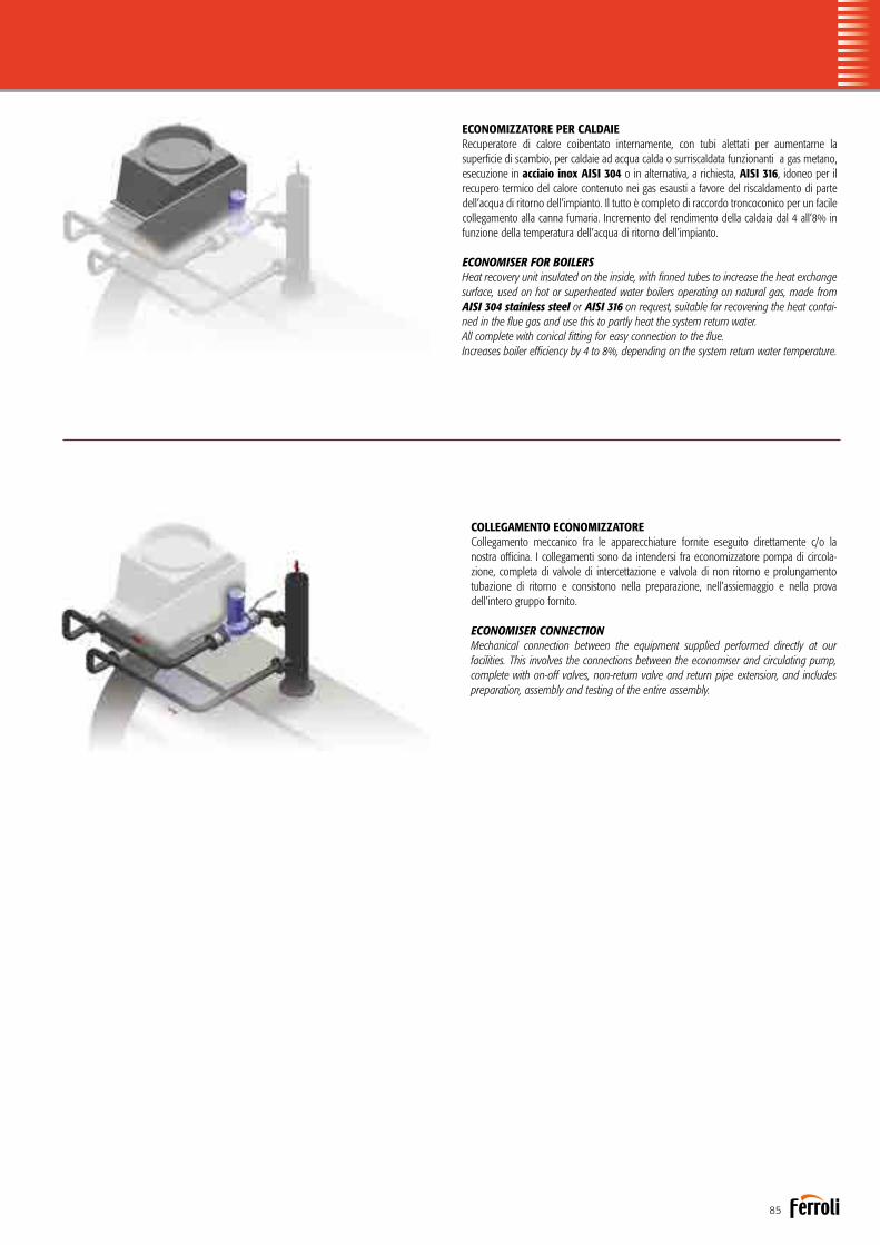
85
ECONOMIZZATORE PER CALDAIERecuperatore di calore coibentato internamente, con tubi alettati per aumentarne la superficie di scambio, per caldaie ad acqua calda o surriscaldata funzionanti a gas metano, esecuzione in acciaio inox AISI 304 o in alternativa, a richiesta, AISI 316, idoneo per il recupero termico del calore contenuto nei gas esausti a favore del riscaldamento di parte dell’acqua di ritorno dell’impianto. Il tutto è completo di raccordo troncoconico per un facile collegamento alla canna fumaria. Incremento del rendimento della caldaia dal 4 all’8% in funzione della temperatura dell’acqua di ritorno dell’impianto.
ECONOMISER FOR BOILERSHeat recovery unit insulated on the inside, with finned tubes to increase the heat exchange surface, used on hot or superheated water boilers operating on natural gas, made from AISI 304 stainless steel or AISI 316 on request, suitable for recovering the heat contai-ned in the flue gas and use this to partly heat the system return water.All complete with conical fitting for easy connection to the flue.Increases boiler efficiency by 4 to 8%, depending on the system return water temperature.
COLLEGAMENTO ECONOMIZZATORECollegamento meccanico fra le apparecchiature fornite eseguito direttamente c/o la nostra officina. I collegamenti sono da intendersi fra economizzatore pompa di circola-zione, completa di valvole di intercettazione e valvola di non ritorno e prolungamento tubazione di ritorno e consistono nella preparazione, nell’assiemaggio e nella prova dell’intero gruppo fornito.
ECONOMISER CONNECTIONMechanical connection between the equipment supplied performed directly at our facilities. This involves the connections between the economiser and circulating pump, complete with on-off valves, non-return valve and return pipe extension, and includes preparation, assembly and testing of the entire assembly.

86
Accessori / Accessories
Vista davanti / Front view
SISTEMA PER L’ESERCIZIO IN ASSENZA DI SUPERVISIONE FINO A 24 hSet accessori per l’ottenimento dell’esonero parziale del fuochista (24 h) secondo UNI/TS 11325-3 composto da: tronchetto strumenti completo di attacchi flangiati, da posizionare sulla mandata del generatore, completo dei seguenti accessori: n° 1 manometro con rubi-netto porta manometro - n° 1 termometro a grande quadrante con indicazione di limite - n° 1 pressostato di sicurezza - n° 1 indicatore di livello a riflessione con rubinetti di inter-cettazione - n° 1 sonda di sicurezza livello minimo - n° 2 gruppi interruttori di temperatura.
SYSTEM FOR UNSUPERVISED OPERATION UP TO 24 hSet of accessories used to obtain partial exemption from supervised operation (24 h) in accordance with legal requirements. Composition: pipe stub for instrument connection with flanged connections to be attached to the boiler outlet, complete with the following accessories: 1 pressure gauge with connection valve - 1 large dial thermometer with limit indicator - 1 safety pressure switch - 1 reflex level gauge with on-off valves - 1 minimum level safety probe - 2 sets of temperature switches.
N.B. - Illustrazione esemplificativa.N.B. - Example illustration.
SISTEMA PER L’ESERCIZIO IN ASSENZA DI SUPERVISIONE FINO A 72 hset accessori per l’ottenimento dell’esonero parziale del fuochista (72 h) secondo UNI/TS 11325-3 e UNI EN 12953-6 composto da: tronchetto strumenti completo di attacchi flangiati, da posizionare sulla mandata del generatore, completo dei seguenti accessori: n° 1 manometro con rubinetto porta manometro - n° 1 termometro a grande quadrante con indicazione di limite - n° 1 pressostato di sicurezza - n° 1 indicatore di livello a rifles-sione con rubinetti di intercettazione - n° 1 sonda di sicurezza livello minimo - n° 2 gruppi interruttori di temperatura auto controllati - n° 1 CTE, sistema di controllo a PLC per la procedura di gestione 72 h.
SYSTEM FOR UNSUPERVISED OPERATION UP TO 72 hSet of accessories used to obtain partial exemption from supervised operation (72 h) in accordance with legal requirements. Composition: pipe stub for instrument connection with flanged connections to be attached to the boiler outlet, complete with the following accessories: 1 pressure gauge with connection valve - 1 large dial thermometer with limit indicator - 1 safety pressure switch - 1 reflex level gauge with on-off valves - 1 minimum level safety probe - 2 sets of automatic temperature switches - 1 CTE, PLC control system for 72 h operation.
Vista davanti / Front view
N.B. - Illustrazione esemplificativa.N.B. - Example illustration.

87
SCALETTA E PASSERELLAScaletta e passerella per accedere in sicurezza alla parte superiore della caldaia, progettati e costruiti in profilati di acciaio al carbonio opportunamente giuntati, come previsto dalle vigenti norme ENPI in materia di sicurezza.
LADDER AND WALKWAYLadder and walkway to safely access the top part of the boiler, designed and built using carbon steel section bars with suitable joints, as required by ENPI safety stan-dards in force.
COIBENTAZIONE CAMERA FUMO T3G F ASL/ASHCoibentazione della camera fumo posteriore, al fine di diminuire le dispersioni termiche attraverso l’involucro, eseguita con materassino in lana di roccia di grosso spessore ed alta densità e protezione tramite lamiera opportunamente piegata e sagomata per poter aderire al meglio con la struttura di caldaia.
SMOKEBOX INSULATION T3G F ASL/ASHInsulation on the rear smokebox to reduce heat loss through the casing, made from a thick layer of high density rock wool and protected by sheet metal bent and shaped to fit the structure of boiler.
VASO DI ESPANSIONEVaso di espansione chiuso per acqua surriscaldata, collaudato, completo di accessori di regolazione e sicurezza e quadro elettrico generale ed in particolare di:nn° 1 indicatore di livello completo di rubinetti di intercettazionenn° 1 manometro con portamanometronn° 1 valvola di sicurezza a norme ISPESLnn° 1 regolatore di livello elettronico a sonde o galleggiante (min-max)nn° 1 sonda di basso livello di sicurezza a riarmo manualenn° 1 elettrovalvola immissione aria (o azoto)nn° 1 pressostato regolazione elettrovalvola (min-max)nn° 1 pressostato di sicurezza a riarmo manualenn° 1 elettropompa di reintegro acqua impiantonn° 1 quadro elettrico generale con selettori, telesalvamotori, fusibili, lampade spia per il comando della logica del sistema
EXPANSION VESSELClosed expansion vessel for superheated water, fully tested, complete with control and safety accessories and main electrical panel, including:n1 level gauge complete with on-off valvesn1 pressure gauge with connectorn1 safety valve to ISPESL standardsn1 electronic level controller, sensor or float (min-max)n1 low level safety sensor with manual resetn1 air (or nitrogen) inlet solenoid valven1 solenoid valve control pressure switch (min-max)n1 safety pressure switch with manual resetn1 motor-driven pump to top-up system watern1 main electrical panel with switches, motor protectors, fuses and indicator lights to control system logic

88
Generatore di vapore a bassa pressione a tre giri di fumo di cui due nel focolare Low pressure steam boiler with three flue passes, two in furnace
VAPOPREX LVPq
Generatore di vapore saturo a bassa pressione ad inversione di fiamma, monoblocco, in acciaio a combustione pressurizzata ed elevata efficienza energetica. Predisposto per funzionare in abbinamento ad un bruciatore ad aria soffiata a combustibile liquido o gassoso. Focolare ad inversione di fiamma e camera di combustione con fondo bagnato e dimensionata in modo tale da assicurare bassi carichi termici. Gamma composta da 7 modelli con potenze utili da 101 kW a 838 kW.nPressione standard di progetto 0,98 bar.nProduzione di vapore da 150 a 1.250 kg/h nIl portellone è fissato sulla piastra tubiera a mezzo cerniere ed è
internamente rivestito con un adeguato spessore di cemento refratta-rio che copre l’intera superficie riscaldata della piastra stessa.
nCamera evaporante abbondantemente dimensionata con un’ampia superficie di scambio per la produzione di vapore saturo di elevata qualità.
Low pressure saturated steam generator with flame reversal, packaged steel structure with pressurised combustion and high energy efficiency. Ready for operation in combination with a jet burner on liquid or gas fuel. Furnace with flame reversal and combustion chamber with cooled end plate sized to ensure low heating loads.Range consisting of 7 models with useful heat outputs from 101 kW to 838 kW.
nStandard design pressure 0.98 bars.nSteam production from 150 to 1,250 kg/h nThe door is hinged to the tube plate; it’s insulated on the
insi-de with a suitable layer of refractory concrete and covers the entire heated surface of the tube plate.
nAmply sized evaporating chamber with large heat exchan- ge area for the production of high quality saturated steam.

89
nHeat loss to the surrounding environment is limited by a layer of high-density mineral wool on the boiler body, without thermal bridges.
nThe parts subject to pressure are all welded by qualified and IIS approved personnel, according to EN standards.
nThese modern-concept and high-efficiency steam generators have been designed and developed in compliance with European Directive 2014/68/UE (PED) and the most recent national and European standards on pressurised recipients.
The water circuit can be inspected through a manhole at the top of the boiler and a hand opening ring at the bottom.
nPainted steel casing.
CERTIFICATIONCE mark in accordance with the following directives Pressure Equipment (2014/68/UE)Low Voltage (2014/35/UE)Electromagnetic Compatibility (2014/30/UE)
nLe dispersioni verso l’ambiente sono molto contenute graziead una adeguata coibentazione del corpo caldaia eseguita con uno strato di lana minerale ad alta densità e senza ponti termici.
nLe saldature delle parti in pressione sono tutte eseguite da personale qualificato ed approvato IIS secondo norme EN.
nDi moderna concezione e ad alto rendimento, questi gene-ratori sono progettati e realizzati nel rispetto della Direttiva Europea 2014/68/UE (PED) e delle più recenti norme nazio-nali ed europee in materia di recipienti a pressione.
nL’ispezionabilità lato acqua è garantita da un passo uomo sul colmo caldaia e un passo mano nella parte inferiore.nMantellatura in acciaio verniciato.
CERTIFICAZIONIMarcatura CE secondo le Direttive Apparecchi a pressione (2014/68/UE)Bassa Tensione (2014/35/UE) Compatibilità Elettromagnetica (2014/30/UE)
Corpo caldaia interamente rivestito con materassino in lana minerale
Boiler body completely lined with rock wool insulation
Gruppo alimentazione
Power supply unit
Attacco valvole di sicurezza
Safety valve connection
Presa vapore
Steam outlet
Gruppo manometri e pressostati
Pressure gauge and pressure switch group
Isolamento portellone in cemento refrattario
Door insulated with refractory concrete
Portellone con apertrua reversibile DX o SX
Door with reversible opening, R or L
Camera di combustionea fondo bagnato
Combustion chamber with cooled end plate
Passo uomo
Manhole
Regolatori livello
Level controllers

90
VAPOPREX LVPqDIMENSIONIDIMENSIONS
Legenda 1 Caldaia 2 Porta 3 Camera fumo 4 Quadro elettrico 5 Tubo livelli 6 Manometro 7 Pressostati 8 Tubo spurgo superficiale (optional) 9 Indicatore livello10 Rubinetti prova livello11 Indicatore livello (optional)12 Passa testa/passo d’uomo13 Pompa alimentazione
Key 1 Boiler 2 Door 3 Smokebox 4 Electrical panel 5 Level pipe 6 Pressure gauge 7 Pressure switches 8 Surface drain pipe (optional) 9 Level gauge10 Level test cocks11 Level indicator (optional)12 Headhole/manhole13 Supply pump
ACCESSORI A CORREDOn 1 pompa acqua alimentazione con valvole intercettazione e ritegnon 1 valvola intercettazione presa vaporen 1 valvola di scarico con valvola di intercettazionen 1 o 2 valvole sicurezza a levan 1 trasduttore di pressionen 1 pressostato di sicurezza n 1 manometro tipo Bourdon con rubinetto a tre vien 1 indicatore livello a riflessione con rubinettin 2 rubinetti controllo livellin 1 sistema di controllo livello acqua ad elettrodin 1 sonda di minimo livello failsafen 1 quadro elettrico industriale
ACCESSORIES SUPPLIEDn 1 water supply pump with on-off and check valvesn 1 steam outlet on-off valven 1 drain valve with on-off valven 1 or 2 lever-operated safety valvesn 1 pressure transmittern 1 safety pressure switchn 1 Bourdon pressure gauge with three-way valven 1 reflex level gauge with valvesn 2 level control valvesn 1 electrode water level control systemn 1 failsafe minimum level proben 1 industrial electrical panel
VAPOPREX LVPq 160 250 400 600 800 1000 1250
DIMENSIONI A mm 1021 1021 1111 1251 1371 1371 1310
DIMENSIONS B mm 1805 1805 2065 2225 2365 2555 2800 C mm 1161 1161 1221 1361 1481 1481 1455 D mm 1305 1305 1395 1535 1655 1655 1625 E mm 880 880 - - 1180 1180 1180 F mm 1260 1260 1270 1410 1530 1530 1545 G mm 455 505 535 600 635 635 635 Alimentazione / Feed T1 1” 1” 1” 1” 1” 1” 1” Presa vapore / Steam outlet T2 DN 50 50 65 80 100 100 100 Scarico sicurezza / Safety discharge T3 DN 50 50 65 80 100 100 100 Scarico / Drain T4 1” 1” 1” 1” 1” 1” 1” Uscita fumo / Flue outlet T5 Ø mm 200 200 250 250 250 250 250 Attacco bruciatore / Burner att. fitting T6 Ø mm 220 220 240 240 270 270 270 Lg. min/max boccaglio / Lenght min/max draught tube burner 250/340 250/340 260/350 260/350 280/370 280/370 280/370 Peso / Weight kg 1040 1040 1340 1670 1980 2050 2340
DATI TECNICITECHNICAL DATA
VAPOPREX LVPq 160 250 400 600 800 1000 1250 Produzione vapore / Steam production 70°C kg/h 150 250 400 600 800 1000 1250
KW 101 168 269 403 537 671 838 Potenza utile / Heat output
kcal/h 86860 144480 231340 346580 461820 577060 720680
Potenza focolare / Heat input kW 112 186 298 447 596 745 931
kcal/h 96320 159960 256280 384420 512560 640700 800660
Contropressione focolare / Furnace backpressure mbar 1,5 2,7 3,5 4,5 5,0 6,0 6,3

91
ACCESSORI A RICHIESTA
nEconomizzatore: è uno scambiatore di calore acqua - fumi che permette di ottenere un incremento del rendimento fino al 5%. La sua configurazione e la collocazione del medesimo sono eseguiti secondo le esigenze del Cliente.
nSistema di alimentazione modulante per la gestione otti-male del livello acqua in accoppiamento con economizzatore.
nBruciatore: marchio e tipologia secondo le indicazioni del cliente.nPiastra porta bruciatore perforata secondo le indicazioni
del cliente.nSeconda pompa alimentazione stand-by con valvolame.nSecondo indicatore livello con rubinetti.nSistema per spurgo automatico di fondo dei depositi di
fanghi e di sali disciolti.nSistema controllo salinità (TDS) per la rilevazione dei sali
disciolti nell’acqua di esercizio.nBarilotto raffreddatore per prelievo campione acqua caldaia.nBMS 24H per esercizio senza supervisione continua fino a 24ore. nBMS 72H per esercizio senza supervisione continua fino a 72 ore.nSeconda sonda di minimo livello FAIL SAFE.nSonda di massimo livello FAIL SAFE.nCertificazione “MODULO F” presso l’utilizzatore.n B.E.C.S. (Boiler Electronic Configurable System): il sistema
dicontrollo B.E.C.S. è costituito da un PLC dotato di interfaccia operatore Touch Panel a colori di elevate prestazioni. Tramite l’interfaccia è possibile supervisionare il funzionamento dell’in-sieme Caldaia-Bruciatore-Impianto.
nVaso raccolta condense VRC.nDegasatore atmosferico VRD.nSerbatoio raffreddatore spurghi “BDV”.nSistema di trattamento acqua.nCollettore vapore.
ACCESSORIES AVAILABLE ON REQUEST
nEconomiser: a water-flue gas heat exchanger that increasesefficiency by up to 5%. Its configuration and position are defined based on customer requirements.
nModulating supply system for optimum water level mana-gement in combination with an economiser.
nBurner: brand and type chosen based on customer specifications.nPerforated burner plate based on customer specifications.nSecond standby supply pump with valves.nSecond level gauge with valves.nSystem for automatically draining sludge and dissolved
salts that deposit on the bottom.nSalinity (TDS) control system that measures dissolved salts
in the water.nCooling tank for sampling boiler water.nBMS 24H for up to 24 hours’ continuous unsupervised operation.nBMS 72H for up to 72 hours’ continuous unsupervised operation.nSecond FAIL SAFE minimum level probe.nFAIL SAFE maximum level probe.nB.E.C.S. (Boiler Electronic Configurable System): the B.E.C.S.
control system consists of a PLC fitted with high performance Touch Panel colour operator interface. The interface can be used to manage operation of the Boiler-Burner-Central Heating System.
n“VRC” condensate collection vessel.n “VRD” atmospheric degasser.n “BDV” drainage cooling tank.n Water treatment system.n Steam manifold.

92
Generatore di vapore a bassa pressione a tre giri di fumo di cui due nel focolare Low pressure steam boiler with three flue passes, two in furnace
VAPOPREX LVP
Generatore di vapore saturo a bassa pressione ad inversione di fiamma, monoblocco, in acciaio a combustione pressurizzata ed elevata efficienza energetica. Predisposto per funzionare in abbinamento ad un bruciatore ad aria soffiata a combustibile liquido o gassoso. Focolare ad inversione di fiamma e camera di combustione con fondo bagnato e dimensionata in modo tale da assicurare bassi carichi termici. Gamma composta da 7 modelli con potenze utili da 1.006 kW a 2.682 kW.nPressione standard di progetto 0,98 bar.nProduzione di vapore da 1.500 a 4.000 kg/h (fino a 2.000
Kg/h di vapore, esonero completo da conduttore patentato).nIl portellone è fissato sulla piastra tubiera a mezzo cerniere ed è
internamente rivestito con un adeguato spessore di cemento refratta-rio che copre l’intera superficie riscaldata della piastra stessa.
nCamera evaporante abbondantemente dimensionata con un’ampia superficie di scambio per la produzione di vapore saturo di elevata qualità.
Low pressure saturated steam generator with flame reversal, packaged steel structure with pressurised combustion and high energy efficiency. Ready for operation in combination with a jet burner on liquid or gas fuel. Furnace with flame reversal and combustion chamber with cooled end plate sized to ensure low heating loads.Range consisting of 7 models with useful heat outputs from 1,006 kW to 2,682 kW.
nStandard design pressure 0.98 bars.nSteam production from 1,500 to 4,000 kg/h (up to 2,000
kg/h of steam with complete exemption from certified opera-tor requirements).
nThe door is hinged to the tube plate; it’s insulated on the insi-de with a suitable layer of refractory concrete and covers the entire heated surface of the tube plate.
nAmply sized evaporating chamber with large heat exchan- ge area for the production of high quality saturated steam.
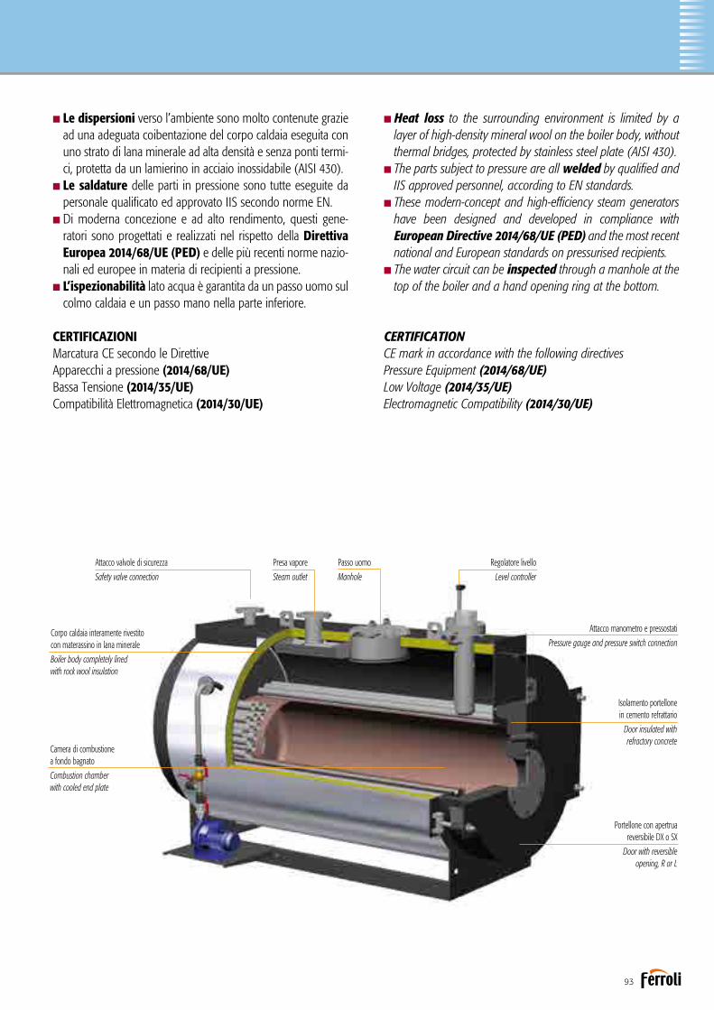
93
nHeat loss to the surrounding environment is limited by a layer of high-density mineral wool on the boiler body, without thermal bridges, protected by stainless steel plate (AISI 430).
nThe parts subject to pressure are all welded by qualified and IIS approved personnel, according to EN standards.
nThese modern-concept and high-efficiency steam generators have been designed and developed in compliance with European Directive 2014/68/UE (PED) and the most recent national and European standards on pressurised recipients.
nThe water circuit can be inspected through a manhole at the top of the boiler and a hand opening ring at the bottom.
CERTIFICATIONCE mark in accordance with the following directives Pressure Equipment (2014/68/UE)Low Voltage (2014/35/UE)Electromagnetic Compatibility (2014/30/UE)
nLe dispersioni verso l’ambiente sono molto contenute graziead una adeguata coibentazione del corpo caldaia eseguita con uno strato di lana minerale ad alta densità e senza ponti termi-ci, protetta da un lamierino in acciaio inossidabile (AISI 430).
nLe saldature delle parti in pressione sono tutte eseguite da personale qualificato ed approvato IIS secondo norme EN.
nDi moderna concezione e ad alto rendimento, questi gene-ratori sono progettati e realizzati nel rispetto della Direttiva Europea 2014/68/UE (PED) e delle più recenti norme nazio-nali ed europee in materia di recipienti a pressione.
nL’ispezionabilità lato acqua è garantita da un passo uomo sul colmo caldaia e un passo mano nella parte inferiore.
CERTIFICAZIONIMarcatura CE secondo le Direttive Apparecchi a pressione (2014/68/UE)Bassa Tensione (2014/35/UE) Compatibilità Elettromagnetica (2014/30/UE)
Corpo caldaia interamente rivestito con materassino in lana minerale
Boiler body completely lined with rock wool insulation
Attacco valvole di sicurezza
Safety valve connection
Presa vapore
Steam outlet
Passo uomo
Manhole
Regolatore livello
Level controller
Attacco manometro e pressostati
Pressure gauge and pressure switch connection
Isolamento portellone in cemento refrattario
Door insulated with refractory concrete
Portellone con apertrua reversibile DX o SX
Door with reversible opening, R or L
Camera di combustionea fondo bagnato
Combustion chamber with cooled end plate

94
VAPOPREX LVPDIMENSIONIDIMENSIONS
VAPOPREX LVP N 1500 1750 2000 2500 3000 3500 4000
DIMENSIONI A mm 1550 1550 1640 1770 1910 1910 2150 DIMENSIONS B mm 1720 1720 1840 2010 2120 2120 2360 C mm 2850 3070 3070 3360 3370 3600 3930 D mm 1720 1720 1840 1970 2080 2080 2320 P mm 715 715 760 855 910 910 1000 Q mm 1320 1320 1440 1580 1700 1700 1900 Presa vapore / Steam outlet a1 DN 125 125 125 150 150 150 200 Alimentazione pompa / Pump inlet a2 DN 1” 1” 1” 1” 1” 1” 1” Scarico / Drain a3 DN 1” 1” 1” 1” 1/2 1” 1/2 1” 1/2 1” 1/2 Uscita fumo / Flue outlet a4 Ø mm 350 350 350 400 400 400 500 Attacco bruciatore / Burner att. fitting a5 Ø mm 300 300 300 360 360 360 430 Lg. min/max boccaglio
a5 mm 360/440 360/440 360/440 360/440 380/480 80/480 380/480 Lenght min/max draught tube burner Scarico sicurezza / Safety discharge a6 DN 125 125 125 2x100 2x125 2x80 2x125 Alimentazione ausiliaria / Auxiliary inlet a9 DN 1” 1” 1” 1” 1” 1” 1” Peso / Weight kg 2650 2790 3180 4300 4620 4800 6460
DATI TECNICITECHNICAL DATA
VAPOPREX LVP N 1500 1750 2000 2500 3000 3500 4000
Produzione vapore / Steam production 70°C kg/h 1500 1750 2000 2500 3000 3500 4000
Potenza nominale / Heat output kW 1006 1174 1341 1676 2012 2347 2682
Potenza focolare / Heat input kW 1117 1304 1490 1862 2235 2607 2980
Contropressione focolare / Furnace backpressure mbar 6,8 7,0 7,0 8,0 8,3 9,1 10,0
Capacità livello minimo / Min. level capacity dm3 1360 1480 1640 2540 2580 2960 4240
Capacità totale / Total capacity dm3 2100 2300 2600 3460 3760 4020 6000
VAPOPREX LVPn 160-4000 Pressione max esercizio / Max working pressure 0,98 bar Pressione prova / Hydraulic test pressure 1,71 bar Temperatura progetto / Design temperature 119,6°C
Disegno N° 3936603/0Data ultima revisione 11/02/2011
Generatore di vapore a bassa pressione Low pressure steam generator
Legenda 1 Caldaia 2 Porta 3 Camera fumo 4 Quadro elettrico 5 Tubo livelli 6 Manometro 7 Pressostati 8 Tubo spurgo superficiale (optional) 9 Indicatore livello10 Rubinetti prova livello11 Indicatore livello (optional)12 Passa testa/passo d’uomo13 Pompa alimentazione
Key 1 Boiler 2 Door 3 Smokebox 4 Electrical panel 5 Level pipe 6 Pressure gauge 7 Pressure switches 8 Surface drain pipe (optional) 9 Level gauge10 Level test cocks11 Level indicator (optional)12 Headhole/manhole13 Supply pump
ACCESSORI A CORREDOn 1 pompa acqua alimentazione con valvole intercettazione e ritegnon 1 valvola intercettazione presa vaporen 1 valvola di scarico con valvola di intercettazionen 1 o 2 valvole sicurezza a levan 1 trasduttore di pressionen 1 pressostato di sicurezzan 1 manometro tipo Bourdon con rubinetto a tre vien 1 indicatore livello a riflessione con rubinettin 2 rubinetti controllo livellin 1 sistema di controllo livello acqua ad elettrodin 1 sonda di minimo livello failsafen 1 quadro elettrico industriale
ACCESSORIES SUPPLIEDn 1 water supply pump with on-off and check valvesn 1 steam outlet on-off valven 1 drain valve with on-off valven 1 or 2 lever-operated safety valvesn 1 pressure transmittern 1 safety pressure switchn 1 Bourdon pressure gauge with three-way valven 1 reflex level gauge with valvesn 2 level control valvesn 1 electrode water level control systemn1 failsafe minimum level proben 1 industrial electrical panel

95
ACCESSORI A RICHIESTA
nEconomizzatore: è uno scambiatore di calore acqua - fumi che permette di ottenere un incremento del rendimento fino al 5%. La sua configurazione e la collocazione del medesimo sono eseguiti secondo le esigenze del Cliente.
nScala e passerella per accedere in sicurezza alla pedana calpestabile sopra la caldaia.
nSistema di alimentazione modulante per la gestione otti-male del livello acqua in accoppiamento con economizzatore.
nBruciatore: marchio e tipologia secondo le indicazioni del cliente.nPiastra porta bruciatore perforata secondo le indicazioni
del cliente.nSeconda pompa alimentazione stand-by con valvolame.nSecondo indicatore livello con rubinetti.nSistema per spurgo automatico di fondo dei depositi di
fanghi e di sali disciolti.nSistema controllo salinità (TDS) per la rilevazione dei sali
disciolti nell’acqua di esercizio.nBarilotto raffreddatore per prelievo campione acqua caldaia.nBMS 24H per esercizio senza supervisione continua fino a 24ore. nBMS 72H per esercizio senza supervisione continua fino a 72 ore.nSeconda sonda di minimo livello FAIL SAFE.nSonda di massimo livello FAIL SAFE.nCertificazione “MODULO F” presso l’utilizzatore.n B.E.C.S. (Boiler Electronic Configurable System): il sistema
dicontrollo B.E.C.S. è costituito da un PLC dotato di interfaccia operatore Touch Panel a colori di elevate prestazioni. Tramite l’interfaccia è possibile supervisionare il funzionamento dell’in-sieme Caldaia-Bruciatore-Impianto.
nVaso raccolta condense VRC.nDegasatore atmosferico VRD.nSerbatoio raffreddatore spurghi “BDV”.nSistema di trattamento acqua.nCollettore vapore.
ACCESSORIES AVAILABLE ON REQUEST
nEconomiser: a water-flue gas heat exchanger that increasesefficiency by up to 5%. Its configuration and position are defined based on customer requirements.
nLadder and walkway for safe access to the walkable plat-form on top of the boiler.
nModulating supply system for optimum water level mana-gement in combination with an economiser.
nBurner: brand and type chosen based on customer specifications.nPerforated burner plate based on customer specifications.nSecond standby supply pump with valves.nSecond level gauge with valves.nSystem for automatically draining sludge and dissolved
salts that deposit on the bottom.nSalinity (TDS) control system that measures dissolved salts
in the water.nCooling tank for sampling boiler water.nBMS 24H for up to 24 hours’ continuous unsupervised operation.nBMS 72H for up to 72 hours’ continuous unsupervised operation.nSecond FAIL SAFE minimum level probe.nFAIL SAFE maximum level probe.nB.E.C.S. (Boiler Electronic Configurable System): the B.E.C.S.
control system consists of a PLC fitted with high performance Touch Panel colour operator interface. The interface can be used to manage operation of the Boiler-Burner-Central Heating System.
n“VRC” condensate collection vessel.n “VRD” atmospheric degasser.n “BDV” drainage cooling tank.n Water treatment system.n Steam manifold.

96
Generatore di vapore a media pressione a tre giri di fumo di cui due nel focolareMedium pressure steam generator with three flue passes, two in furnace
VAPOPREX HVPq
Generatore di vapore saturo a media pressione ad inversione di fiamma, monoblocco in acciaio, a combustione pressurizzata ed elevata efficienza energetica. Predisposto per funzionare in abbinamento ad un bruciatore ad aria soffiata a combustibile liquido o gassoso. Focolare ad inversione di fiamma e camera di combustione con fondo bagnato e dimensionata in modo tale da assicurare bassi carichi termici. Gamma composta da 7 modelli con potenze utili da 105 kW a 867 kW.nPressione standard di progetto 12 bar, 14,8 bar (a richiesta, pressioni superiori).nProduzione di vapore da 150 a 1.250 kg/h. nIl portellone è fissato sulla piastra tubiera a mezzo cerniere
ed è internamente rivestito con un adeguato spessore di cemento refrattario che copre l’intera superficie riscaldata della piastra stessa.
nCamera evaporante abbondantemente dimensionata con un’ampia superficie di scambio per la produzione di vapore saturo di elevata qualità.
Medium pressure saturated steam generator with flame rever-sal, packaged steel structure with pressurised combustion and high energy efficiency. Ready for operation in combination with a jet burner on liquid or gas fuel. Furnace with flame reversal and combustion chamber with cooled end plate sized to ensure low heating loads.Range consisting of 7 models with useful heat outputs from 105 kW to 867 kW.
nStandard design pressure 12 bars, 14.8 bars (higher pressure upon request).nSteam production from 150 to 1,250 kg/h.nThe door is hinged to the tube plate; it’s insulated on the
inside with a suitable layer of refractory concrete and covers the entire heated surface of the tube plate.
nAmply sized evaporating chamber with large heat exchan-ge area for the production of high quality saturated steam.
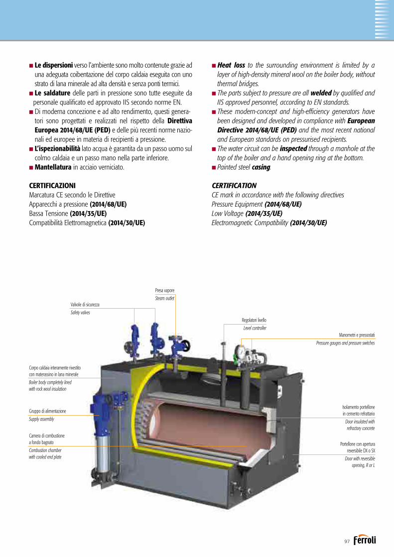
97
nHeat loss to the surrounding environment is limited by a layer of high-density mineral wool on the boiler body, without thermal bridges.
nThe parts subject to pressure are all welded by qualified and IIS approved personnel, according to EN standards.
nThese modern-concept and high-efficiency generators have been designed and developed in compliance with European Directive 2014/68/UE (PED) and the most recent national and European standards on pressurised recipients.
nThe water circuit can be inspected through a manhole at the top of the boiler and a hand opening ring at the bottom.nPainted steel casing.
CERTIFICATIONCE mark in accordance with the following directivesPressure Equipment (2014/68/UE)Low Voltage (2014/35/UE)Electromagnetic Compatibility (2014/30/UE)
nLe dispersioni verso l’ambiente sono molto contenute grazie ad una adeguata coibentazione del corpo caldaia eseguita con uno strato di lana minerale ad alta densità e senza ponti termici.
nLe saldature delle parti in pressione sono tutte eseguite da personale qualificato ed approvato IIS secondo norme EN.
nDi moderna concezione e ad alto rendimento, questi genera-tori sono progettati e realizzati nel rispetto della Direttiva Europea 2014/68/UE (PED) e delle più recenti norme nazio-nali ed europee in materia di recipienti a pressione.
nL’ispezionabilità lato acqua è garantita da un passo uomo sul colmo caldaia e un passo mano nella parte inferiore.nMantellatura in acciaio verniciato.
CERTIFICAZIONIMarcatura CE secondo le Direttive Apparecchi a pressione (2014/68/UE)Bassa Tensione (2014/35/UE) Compatibilità Elettromagnetica (2014/30/UE)
Portellone con apertura reversibile DX o SX
Door with reversible opening, R or L
Isolamento portellone in cemento refrattario
Door insulated with refractory concrete
Regolatori livello
Level controller
Presa vapore
Steam outletValvole di sicurezza
Safety valves
Corpo caldaia interamente rivestito con materassino in lana minerale
Boiler body completely lined with rock wool insulation
Gruppo di alimentazione
Supply assembly
Camera di combustionea fondo bagnato
Combustion chamber with cooled end plate
Manometri e pressostati
Pressure gauges and pressure switches

98
VAPOPREX HVPqDIMENSIONIDIMENSIONS
DATI TECNICITECHNICAL DATA
VAPOPREX HVPq 160 250 400 600 800 1000 1250
Produzione vapore / Steam production Alim. 70°C kg/h 150 250 400 600 800 1000 1250
Potenza nominale / Heat output kW 105 174 278 417 555 694 867
Potenza focolare / Heat input kW 116 193 308 463 616 771 963
Contropressione focolare / Furnace backpressure mbar 1,5 2,7 3,5 4,5 5,0 6,0 6,3
Capacità livello minimo / Min. level capacity dm3 280 360 490 720 980 1080 1190
Capacità totale / Total capacity dm3 420 490 700 985 1360 1500 1650
Legenda 1 Caldaia 2 Porta 3 Camera fumo 4 Quadro elettrico 5 Tubo livelli 6 Manometro 7 Pressostati 8 Tubo spurgo superficiale (optional) 9 Indicatore livello10 Indicatore livello (optional)11 Passa testa/passo d’uomo12 Pompa alimentazione
Key 1 Boiler 2 Door 3 Smokebox 4 Electrical panel 5 Level pipe 6 Pressure gauge 7 Pressure switches 8 Surface drain pipe (optional) 9 Level gauge10 Level indicator (optional)11 Headhole/manhole12 Supply pump
ACCESSORI A CORREDOn 1 pompa acqua alimentazione con valvole intercettazione e ritegnon 1 valvola intercettazione presa vaporen 1 valvola di scarico con valvola di intercettazionen 1 o 2 valvole sicurezza a levan 1 trasduttore di pressionen 1 pressostato di sicurezzan 1 manometro tipo Bourdon con rubinetto a tre vien 1 indicatore livello a riflessione con rubinettin 2 rubinetti controllo livellin 1 sistema di controllo livello acqua ad elettrodin 1 sonda di minimo livello failsafen 1 quadro elettrico industriale
ACCESSORIES SUPPLIEDn 1 water supply pump with on-off and check valvesn 1 steam outlet on-off valven 1 drain valve with on-off valven 1 or 2 lever-operated safety valvesn 1 pressure transmittern 1 safety pressure switchn 1 Bourdon pressure gauge with three-way valven 1 reflex level gauge with valvesn 2 level control valvesn 1 electrode water level control systemn 1 failsafe minimum level proben 1 industrial electrical panel
VAPOPREX HVPq 160 250 400 600 800 1000 1250
DIMENSIONI A mm 910 990 1080 1220 1350 1350 1350 DIMENSIONS B mm 1270 1270 1530 1670 1830 2020 2800 C mm 1035 1125 1215 1335 1455 1455 1455 D mm 1185 1260 1350 1490 1620 1620 1620 E mm 845 890 930 1060 1180 1180 1180 F mm 1120 1205 1295 1425 1545 1545 1545 G mm 455 505 535 600 635 635 635 Alimentazione pompa / Pump inlet T1 DN 25 25 25 25 25 25 25 Presa vapore / Steam outlet T2 DN 25 25 32 40 50 50 50 Scarico sicurezza / Safety discharge T3 DN 2x40 2x40 2x40 2x40 2x40 2x40 2x40 Scarico / Drain T4 DN 25 25 25 25 25 25 25 Uscita fumo / Flue outlet T5 Ø mm 200 200 250 250 250 250 250 Attacco bruciatore / Burner att. fitting T6 Ø mm 220 220 240 240 270 270 270 Lg. min/max boccaglio
T6 mm 250/340 250/340 260/350 260/350 280/370 280/370 280/370 Lenght min/max draught tube burner Peso / Weight 12 bar kg 980 1180 1550 2150 2480 2600 2780

99
ACCESSORI A RICHIESTA
nEconomizzatore: è uno scambiatore di calore acqua - fumi che permette di ottenere un incremento del rendimento fino al 5%. La sua configurazione e la collocazione del medesimo sono eseguiti secondo le esigenze del Cliente.
nSistema di alimentazione modulante per la gestione ottimale del livello acqua adatto in accoppiamento con economizzatore.
nBruciatore: marchio e tipologia secondo le indicazioni del cliente.nPiastra porta bruciatore perforata secondo le indicazioni
del cliente.nSeconda pompa alimentazione stand-by con valvolame.nSecondo indicatore livello con rubinetti (dal mod. 160 al 600).nSistema per spurgo automatico di fondo dei depositi di
fanghi e di sali disciolti.nSistema controllo salinità (TDS) per la rilevazione dei sali
disciolti nell’acqua di esercizio.nBarilotto raffreddatore per prelievo campione acqua caldaia.nBMS 24H per esercizio senza supervisione continua fino a 24 ore. nBMS 72H per esercizio senza supervisione continua fino a 72 ore.nSeconda sonda di minimo livello FAIL SAFE.nSonda di massimo livello FAIL SAFE.nCertificazione “MODULO F” presso l’utilizzatore.nB.E.C.S. (Boiler Electronic Configurable System): il sistema di
controllo B.E.C.S. è costituito da un PLC dotato di interfaccia operatore Touch Panel a colori di elevate prestazioni. Tramite l’interfaccia è possibile supervisionare il funzionamento dell’in-sieme Caldaia-Bruciatore-Impianto.
nVaso raccolta condense VRC.nDegasatore atmosferico VRD.nDegasatore termofisicio “DGST”.nSerbatoio raffreddatore spurghi “BDV”.nSistema di trattamento acqua.nCollettore vapore.
ACCESSORIES AVAILABLE ON REQUEST
nEconomiser: a water-flue gas heat exchanger that increases efficiency by up to 5%. Its configuration and position are defi-ned based on customer requirements.
nModulating supply system for optimum water level mana-gement in combination with an economiser.
nBurner: brand and type chosen based on customer specifications.nPerforated burner plate based on customer specifications.nSecond standby supply pump with valves.nSecond level gauge with valves (from mod. 160 to 600).nSystem for automatically draining sludge and dissolved
salts that deposit on the bottom.nSalinity (TDS) control system that measures dissolved salts
in the water.nCooling tank for sampling boiler water.nBMS 24H for up to 24 hours’ continuous unsupervised ope-ration.nBMS 72H for up to 72 hours’ continuous unsupervised ope-ration.nSecond FAIL SAFE minimum level probe.nFAIL SAFE maximum level probe.nB.E.C.S. (Boiler Electronic Configurable System): the B.E.C.S.
control system consists of a PLC fitted with high performance Touch Panel colour operator interface. The interface can be used to manage operation of the Boiler-Burner-Central Heating System.
n“VRC” condensate collection vessel.n “VRD” atmospheric degasser.n “DGST” thermophysical degasser.n “BDV” drainage cooling tank.n Water treatment system.n Steam manifold.

100
Generatore di vapore a media pressione a tre giri di fumo di cui due nel focolareMedium pressure steam generator with three flue passes, two in furnace
VAPOPREX HVP
Generatore di vapore saturo a media pressione ad inversione di fiamma, monoblocco in acciaio, a combustione pressurizzata ed elevata efficienza energetica. Predisposto per funzionare in abbinamento ad un bruciatore ad aria soffiata a combustibile liquido o gassoso. Focolare ad inversione di fiamma e camera di combustione con fondo bagnato e dimensionata in modo tale da assicurare bassi carichi termici. Gamma composta da 8 modelli con potenze utili da 1.041 kW a 3.467 kW.nPressione standard di progetto 12 bar, 14,8 bar (a richiesta, pressioni superiori).nProduzione di vapore da 1.500 a 5.000 kg/h. nIl portellone è fissato sulla piastra tubiera a mezzo cerniere
ed è internamente rivestito con un adeguato spessore di cemento refrattario che copre l’intera superficie riscaldata della piastra stessa.
nCamera evaporante abbondantemente dimensionata con un’ampia superficie di scambio per la produzione di vapore saturo di elevata qualità.
Medium pressure saturated steam generator with flame rever-sal, packaged steel structure with pressurised combustion and high energy efficiency. Ready for operation in combination with a jet burner on liquid or gas fuel. Furnace with flame reversal and combustion chamber with cooled end plate sized to ensure low heating loads.Range consisting of 8 models with useful heat outputs from 1,041 kW to 3,467 kW.
nStandard design pressure 12 bars, 14.8 bars (higher pressure upon request).nSteam production from 1,500 to 5,000 kg/h.nThe door is hinged to the tube plate; it’s insulated on the
inside with a suitable layer of refractory concrete and covers the entire heated surface of the tube plate.
nAmply sized evaporating chamber with large heat exchan-ge area for the production of high quality saturated steam.

101
nHeat loss to the surrounding environment is limited by a layer of high-density mineral wool on the boiler body, without thermal bridges, protected by stainless steel plate (AISI 430).
nThe parts subject to pressure are all welded by qualified and IIS approved personnel, according to EN standards.
nThese modern-concept and high-efficiency generators have been designed and developed in compliance with European Directive 2014/68/UE (PED) and the most recent national and European standards on pressurised recipients.
nCertified as an assembly in accordance with the PED Directive.nThe water circuit can be inspected through a manhole at the top of the boiler and a hand opening ring at the bottom.
CERTIFICATIONCE mark in accordance with the following directivesPressure Equipment (2014/68/UE)Low Voltage (2014/35/UE)Electromagnetic Compatibility (2014/30/UE)
nLe dispersioni verso l’ambiente sono molto contenute graziead una adeguata coibentazione del corpo caldaia eseguita con uno strato di lana minerale ad alta densità e senza ponti termi-ci, protetta da un lamierino in acciaio inossidabile (AISI 430).
nLe saldature delle parti in pressione sono tutte eseguite da personale qualificato ed approvato IIS secondo norme EN.
nDi moderna concezione e ad alto rendimento, questi genera-tori sono progettati e realizzati nel rispetto della Direttiva Europea 2014/68/UE (PED) e delle più recenti norme nazio-nali ed europee in materia di recipienti a pressione.
nCertificazione come insieme secondo Direttiva PED.nL’ispezionabilità lato acqua è garantita da un passo uomo sul colmo caldaia e un passo mano nella parte inferiore.
CERTIFICAZIONIMarcatura CE secondo le Direttive Apparecchi a pressione (2014/68/UE)Bassa Tensione (2014/35/UE) Compatibilità Elettromagnetica (2014/30/UE)
Corpo caldaia interamente rivestito con materassino in lana minerale
Boiler body completely lined with rock wool insulation
Gruppo di alimentazione
Supply assembly
Attacco valvole di sicurezza
Safety valve connection
Presa vapore
Steam outlet
Passo uomo
Manhole
Regolatori livello
Level controller
Attacco manometro e pressostati
Pressure gauge and pressure switch connection
Isolamento portellone in cemento refrattario
Door insulated with refractory concrete
Portellone con apertura reversibile DX o SX
Door with reversible opening, R or L
Camera di combustionea fondo bagnato
Combustion chamber with cooled end plate

102
VAPOPREX HVPDIMENSIONIDIMENSIONS
Legenda 1 Caldaia 2 Porta 3 Camera fumo 4 Quadro elettrico 5 Tubo livelli 6 Manometro 7 Pressostati 8 Tubo spurgo superficiale 9 Indicatore livello10 Rubinetti prova livello11 Indicatore livello (optional)12 Passa testa/passo d’uomo13 Pompa alimentazione
Key 1 Boiler 2 Door 3 Smokebox 4 Electrical panel 5 Level pipe 6 Pressure gauge 7 Pressure switches 8 Surface drain pipe 9 Level gauge10 Level test cocks11 Level indicator (optional)12 Headhole/manhole13 Supply pump
VAPOPREX HVPn 160-5000 Pressione max esercizio / Max working pressure 12 bar Pressione prova / Hydraulic test pressure 21 bar Temperatura progetto / Design temperature 191,7°C
Disegno N° 3936604/0Data ultima revisione 11/02/2011
Generatore di vapore a media pressione Medium pressure steam generator
ACCESSORI A CORREDOn 1 pompa acqua alimentazione con valvole intercettazione e ritegnon 1 valvola intercettazione presa vaporen 1 valvola di scarico a leva con valvola di intercettazionen 2 valvole sicurezza a mollan 1 trasduttore di pressionen 1 pressostato di sicurezzan 1 manometro tipo Bourdon con rubinetto a tre vien 1 o 2 indicatori livello a riflessione con rubinettin 1 sistema di controllo livello acqua ad elettrodin 1 sonda di minimo livello failsafen 1 quadro elettrico industriale
ACCESSORIES SUPPLIEDn 1 water supply pump with on-off and check valvesn 1 steam outlet on-off valven 1 lever-operated valve with on-off valven 2 spring-loaded safety valvesn 1 pressure transmittern 1 safety pressure switchn 1 Bourdon pressure gauge with three-way valven 1 or 2 reflex level gauges with valvesn 1 electrode water level control systemn 1 failsafe minimum level proben 1 industrial electrical panel
VAPOPREX HVP N 1500 1750 2000 2500 3000 3500 4000 5000
DIMENSIONI A mm 1550 1550 1640 1770 1910 1910 2150 2230 DIMENSIONS B mm 1720 1720 1840 2010 2120 2120 2360 2430 C mm 2850 3070 3070 3360 3370 3600 3930 4840 D mm 1770 1770 1890 2020 2130 2130 2400 2480 P mm 715 715 760 855 910 910 1000 1035 Q mm 1320 1320 1440 1580 1700 1700 1900 1920 Presa vapore / Steam outlet a1 DN 65 65 65 80 80 80 100 100 Alimentazione pompa / Pump inlet a2 DN 32 32 32 32 32 32 40 40 Scarico / Drain a3 DN 25 25 25 40 40 40 40 40 Uscita fumo / Flue outlet a4 Ø mm 350 350 350 400 400 400 500 500 Attacco bruciatore / Burner att. fitting a5 Ø mm 300 300 300 360 360 360 430 430 Lg. min/max boccaglio
a5 mm 360/440 360/440 360/440 360/440 380/480 380/480 380/480 400/500 Lenght min/max draught tube burner Scarico sicurezza / Safety discharge a6 DN 2x40 2x40 2x40 2x40 2x40 2x40 2x50 2x50 Peso / Weight 12 bar kg 3650 3900 4600 5600 6500 6900 8700 11500
DATI TECNICITECHNICAL DATA
VAPOPREX HVP N 1500 1750 2000 2500 3000 3500 4000 5000
Produzione vapore / Steam production Alim. 70°C kg/h 1500 1750 2000 2500 3000 3500 4000 5000
Potenza nominale / Heat output kW 1041 1214 1387 1734 2081 2427 2774 3467
Potenza focolare / Heat input kW 1156 1348 1541 1926 2312 2696 3082 3852
Contropressione focolare / Furnace backpressure mbar 6,8 7,0 7,0 8,0 8,3 9,1 10,0 10,5
Capacità livello minimo / Min. level capacity dm3 1360 1480 1640 2540 2580 2960 4240 5060
Capacità totale / Total capacity dm3 2100 2300 2600 3460 3760 4020 6000 8060
* Dimensioni superiori: verifica fattibilità su richiesta* On request we evaluate the feasibility for higher powers
*
*

103
ACCESSORI A RICHIESTA
nEconomizzatore: è uno scambiatore di calore acqua - fumi che permette di ottenere un incremento del rendimento fino al 5%. La sua configurazione e la collocazione del medesimo sono eseguiti secondo le esigenze del Cliente.
nScala e passerella per accedere in sicurezza alla pedana calpestabile sopra la caldaia.
nSistema di alimentazione modulante per la gestione ottimale del livello acqua adatto in accoppiamento con economizzatore.
nBruciatore: marchio e tipologia secondo le indicazioni del cliente.nPiastra porta bruciatore perforata secondo le indicazioni
del cliente.nSeconda pompa alimentazione stand-by con valvolame.nSistema per spurgo automatico di fondo dei depositi di
fanghi e di sali disciolti.nSistema controllo salinità (TDS) per la rilevazione dei sali
disciolti nell’acqua di esercizio.nBarilotto raffreddatore per prelievo campione acqua caldaia.nBMS 24H per esercizio senza supervisione continua fino a 24 ore. nBMS 72H per esercizio senza supervisione continua fino a 72 ore.nSeconda sonda di minimo livello FAIL SAFE.nSonda di massimo livello FAIL SAFE.nCertificazione “MODULO F” presso l’utilizzatore.nB.E.C.S. (Boiler Electronic Configurable System): il sistema di
controllo B.E.C.S. è costituito da un PLC dotato di interfaccia operatore Touch Panel a colori di elevate prestazioni. Tramite l’interfaccia è possibile supervisionare il funzionamento dell’in-sieme Caldaia-Bruciatore-Impianto.
nVaso raccolta condense VRC.nDegasatore atmosferico VRD.nDegasatore termofisico “DGST”.nSerbatoio raffreddatore spurghi “BDV”.nSistema di trattamento acqua.nCollettore vapore.
ACCESSORIES AVAILABLE ON REQUEST
nEconomiser: a water-flue gas heat exchanger that increases efficiency by up to 5%. Its configuration and position are defi-ned based on customer requirements.
nLadder and walkway for safe access to the walkable plat-form on top of the boiler.
nModulating supply system for optimum water level mana-gement in combination with an economiser.
nBurner: brand and type chosen based on customer specifications.nPerforated burner plate based on customer specifications.nSecond standby supply pump with valves.nSystem for automatically draining sludge and dissolved
salts that deposit on the bottom.nSalinity (TDS) control system that measures dissolved salts
in the water.nCooling tank for sampling boiler water.nBMS 24H for up to 24 hours’ continuous unsupervised ope-ration.nBMS 72H for up to 72 hours’ continuous unsupervised ope-ration.nSecond FAIL SAFE minimum level probe.nFAIL SAFE maximum level probe.nB.E.C.S. (Boiler Electronic Configurable System): the B.E.C.S.
control system consists of a PLC fitted with high performance Touch Panel colour operator interface. The interface can be used to manage operation of the Boiler-Burner-Central Heating System.
n“VRC” condensate collection vessel.n “VRD” atmospheric degasser.n “DGST” thermophysical degasser.n “BDV” drainage cooling tank.n Water treatment system.n Steam manifold.

104
Generatore di vapore a media pressione a tre giri effettivi di fumoMedium pressure steam boiler with three flue passes
VP 3G
Generatore di vapore saturo a media pressione, monoblocco in acciaio, a combustione pressurizzata ed elevata efficienza ener-getica. Predisposto per funzionare in abbinamento ad un bru-ciatore ad aria soffiata a combustibile liquido o gassoso. Caldaia a tre giri di fumo con camera di combustione a fondo bagnato e dimensionata in modo tale da assicurare bassi carichi termici.Gamma composta da 7 modelli con potenze utili da 504 kW a 2.770 kW.
nPressione standard di progetto 12 bar, 15 bar (a richiesta, pressioni superiori).nProduzione di vapore (a 12 bar) da 0,7 a 4 t/h. nCamera evaporante abbondantemente dimensionata con
un’ampia superficie di scambio per la produzione di vapore saturo di elevata qualità.
nBruciatore fissato sulla piastra porta bruciatore.nPulizia fascio tubiero attraverso porte d’ispezione anteriore
e posteriore.
Medium pressure saturated steam generator, packaged steel structure with pressurised combustion and high energy efficiency. Ready for operation in combination with a jet burner on liquid or gas fuel. Boiler with three flue passes, combustion chamber with cooled end plate sized to ensure low heating loads. Range consisting of 7 models with useful heat outputs from 504 kW to 2,770 kW.
nStandard design pressure 12 bars, 15 bars (higher pressure upon request).nSteam production (at 12 bars) from 0.7 to 4 t/h.nAmply sized evaporating chamber with large heat exchan-
ge area for the production of high quality saturated steam.nBurner fixed to the burner anchor plate.nTube bundle can be cleaned through front and rear inspec-
tion doors.

105
nPossibility to access the furnace by removing the rear cover plate.
nHeat loss to the surrounding environment is limited by a sui-table layer of high-density mineral wool insulation on the boiler body.
nThe parts subject to pressure are all welded by qualified and IIS approved personnel, according to EN standards.
nThese modern-concept and high-efficiency generators have been designed and developed in compliance with European directive 2014/68/UE (PED) and the most recent national and European standards on pressurised recipients.
nThe water circuit can be inspected through oval-shaped manholes hand head holes.
CERTIFICATIONCE mark in accordance with the following directivesPressure Equipment (2014/68/UE)Low Voltage (2014/35/UE)Electromagnetic Compatibility (2014/30/UE)
nPossibilità di accesso al focolare tramite la rimozione del tampone posteriore.
nLe dispersioni verso l’ambiente sono molto contenute grazie ad una adeguata coibentazione del corpo caldaia eseguita con uno strato di lana minerale ad alta densità.
nLe saldature delle parti in pressione sono tutte eseguite da personale qualificato ed approvato IIS secondo norme EN.
nDi moderna concezione e ad alto rendimento, questi gene-ratori sono progettati e realizzati nel rispetto della Direttiva Europea 2014/68/UE (PED) e delle più recenti norme nazio-nali ed europee in materia di recipienti a pressione.
nL’ispezionabilità lato acqua è garantita da passi uomo e passa testa ovali sul lato acqua.
CERTIFICAZIONIMarcatura CE secondo le Direttive Apparecchi a pressione (2014/68/UE)Bassa Tensione (2014/35/UE) Compatibilità Elettromagnetica (2014/30/UE)
Corpo caldaia interamente rivestito con materassino in lana minerale
Boiler body completely lined with rock wool insulation
Valvole di sicurezza
Safety valves Presa vapore
Steam outlet
Passo uomo
Manhole
Isolamento portellone in fibra ceramica
Door insulated with ceramic filler
Camera di combustionea fondo bagnato
Combustion chamber with cooled end plate
Ingresso acqua
Water inlet
Regolatori livello
Level controller
Gruppo pressostati e manometro
Pressure switch and pressuregange assembly
Valvola di scarico leva completa di valvola di intercettazione
Lever operated drain valve completewith on-off valve
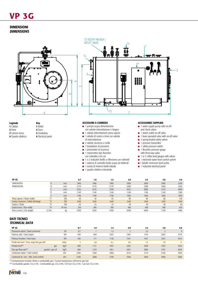
106
VP 3GDIMENSIONIDIMENSIONS
Legenda1 Caldaia2 Porta3 Camera fumo4 Quadro elettrico
Key1 Boiler2 Door3 Smokebox4 Electrical panel
ACCESSORI A CORREDOn 1 pompa acqua alimentazione con valvole intercettazione e ritegnon 1 valvola intercettazione presa vaporen 1 valvola di scarico a leva con valvola di intercettazionen 2 valvole sicurezza a mollan 1 trasduttore di pressionen 1 pressostato di sicurezzan 1 manometro tipo Bourdon con rubinetto a tre vien 1 o 2 indicatori livello a riflessione con rubinettin 1 sistema di controllo livello acqua ad elettrodin 1 sonda di minimo livello failsafen 1 quadro elettrico industriale
ACCESSORIES SUPPLIEDn 1 water supply pump with on-off and check valvesn 1 steam outlet on-off valven 1 lever-operated valve with on-off valven 2 spring-loaded safety valvesn 1 pressure transmittern 1 safety pressure switchn 1 Bourdon pressure gauge with three-way valven 1 or 2 reflex level gauges with valvesn 1 electrode water level control systemn 1 failsafe minimum level proben 1 industrial electrical panel
VP 3G 1.0÷3.0Disegno / Drawing Nr. 39368881Generatore di vapore
Steam generator
FERROLI S.p.A. si riserva a termini di legge la propietà del presente disegno con divieto di riprodurlo o comunicarlo senza sua autorizzazione. L'Azienda precisa che le caratteristiche estetiche e/o dimensionali, i dati tecnici e gli accessori possono essere soggetti a variazione.
FERROLI S.p.A. reserved accordingly current laws this drawing's property with its reproducing and development prohibition without his authorization. The Company stresses that appearance and/or size, technical specifications and accessories may be subject to varation.
Pressione max esercizio *Pressione provaTemperatura progetto
Max working pressure *Hydraulic test pressureDesign temperature
12 bar21 bar191,7 °C
** Pressione max esercizio a richiesta:** Max working pressure on request: 15 bar / 18 bar
Legenda 1 Caldaia 2 Porta 3 Camera Fumo 4 Quadro elettrico
Key 1 Boiler 2 Door 3 Smokebox 4 Electrical panel
KW
Kg/h
KWPotenza utile - Heat output
Portata** fumi
Potenza focolare - Heat input
1.0694771
1131
VP 3G
kg 5200Peso a secco - Dry weightT1
T3T4ABC
50
300
T2 25Presa vapore - Steam outlet
sicurezze - safetyscarico - drain
uscita fumo - flue outlet
ATTA
CCHI
DE
DIMENSIONI - DIMENSIONS
19002170323511401790
t/hProduzione vapore - Steam production Alim. 80° 1
25FITTIN
G
DNDNDNØmmmmmmmmmmmm
Kg/h 1234gas
gasolio - gas oilFlue gas flow -rate**
mbarPerdite lato fumi - Press. drop flue gas side* 5,6
** Combustibile gasolio: CO² = 13% - Combustibile gas: CO² = 10% / Oil fuel: CO² = 13% - Gas fuel: CO² = 10%* Contropressione focolare riferita a combustibile gas / Furnace backpressure referred to gas fuel
1.510411156
1697
545065
300
25
19002170339011401790
1,5
25
1851
6,1
2.013871541
2262
630080
400
25
20002280363511601850
2
40
2467
6,4
2.517441937
2828
660080
400
25
20002280388511601850
2,5
40
3084
7,3
3.020352261
3393
710080
400
25
20002280413511601850
3
40
3701
7,8
dm³Contenuto totale - Total contentdm³Contenuto liv. min. - Min. level content
3400 3660 4310 4710 51002800 2700 3300 3600 3900
ACCESSORI A CORREDO- 1 pompa acqua alimentazione con valvole intercettazione e ritegno- 1 valvola intercettazione presa vapore- 1 valvola di scarico a leva con valvola di intercettazione- 2 valvole sicurezza a molla- 2 pressostati di lavoro RT- 1 pressostato di sicurezza RT- 1 manometro tipo Bourdon con rubinetto a tre vie- 1 o 2 indicatori di livello a riflessione con rubinetti- 1 sistema di controllo livello acqua ad elettrodi- 1 quadro elettrico industriale
ACCESSORIES SUPPLIED- 1 water supply pump with on-off avd check valves- 1 steam outlet on-off valve- 1 lever-operated valve with on-off valve- 2 spring-loaded safety valves- 2 RT operating pressure switches- 1 RT safety pressure switch- 1 Bourdon pressure gauge with three-way valve- 1 or 2 reflex level gauges with valves- 1 electrode water level control system- 1 industrial electrical panel
A
B
C
E
T11
T2 USCITA VALVOLA / OUTLET VALVE
3
T3
4
2
T4
D
VP 3G 0.7 1.0 1.5 2.0 2.5 3.0 4.0
DIMENSIONI A mm 1900 1900 1900 2000 2000 2000 2200 DIMENSIONS B mm 2170 2170 2170 2280 2280 2280 2500 C mm 3235 3235 3390 3635 3885 4135 4690 D mm 1140 1140 1140 1160 1160 1160 1280 E mm 1790 1790 1790 1850 1850 1850 1950 Presa vapore / Steam outlet T1 DN 50 50 65 80 80 80 100 Scarico sicurezze / Safety discharge T2 DN 2x40 2x40 2x40 2x40 2x40 2x40 2x50 Scarico / Drain T3 DN 25 25 25 40 40 40 40 Uscita fumo / Flue outlet T4 Ø mm 250 300 300 400 400 400 450 Peso a secco / Dry weight 12 bar kg 5200 5200 5450 6300 6600 7100 7800
DATI TECNICITECHNICAL DATA
* Contropressione focolare riferita a combustibile gas / Furnace backpressure referred to gas fuel** Combustibile gasolio: CO2=13% - Combustibile gas: CO2=10% / Oil fuel: CO2=13% - Gas fuel: CO2=10%
VP 3G 0.7 1.0 1.5 2.0 2.5 3.0 4.0 Produzione vapore / Steam production t/h 0,7 1 1,5 2 2,5 3 4 Potenza utile / Heat output kW 504 694 1041 1387 1744 2035 2770
Potenza focolare / Heat input kW 560 771 1156 1541 1937 2261 3075
Perdite lato fumi* / Press. dropo flue gas side* mbar 5 5,6 6,1 6,4 7,3 7,8 11
Portata fumi** gas kg/h 800 1131 1697 2262 2828 3393 4524
Flue gas flow-rate** gasolio / gas oil kg/h 849 1234 1851 2467 3084 3701 4934 Contenuto totale / Total content dm3 2260 3400 3660 4310 4710 5100 7850
Contenuto liv. min. / Min. level content dm3 2100 2800 2700 3300 3600 3900 5900

107
ACCESSORI A RICHIESTA
nEconomizzatore: è uno scambiatore di calore acqua-fumi che permette di ottenere un incremento del rendimento fino al 5%. La sua configurazione e la collocazione del medesimo sono eseguiti secondo le esigenze del Cliente.
nScala e passerella per accedere in sicurezza alla pedana calpestabile sopra la caldaia.
nSistema di alimentazione modulante per la gestione otti-male del livello acqua adatto in accoppiamento con economizzatore.
nPreriscaldatore d’aria: è uno scambiatore fumi/aria che va inserito nel circuito fumi tra caldaia e camino. Consente recuperi di rendimento termico dell’ordine del 4%. Per tale soluzione è necessario disporre di un bruciatore tipo industriale con ventila-tore separato da montare a monte del preriscaldatore stesso.
nBruciatore: marchio e tipologia secondo le indicazioni del cliente.nSeconda pompa alimentazione stand-by con valvolame.nSistema per spurgo automatico di fondo dei depositi di
fanghi e di sali disciolti.nSistema controllo salinità (TDS) per la rilevazione dei sali
disciolti nell’acqua di esercizio.nBarilotto raffreddatore per prelievo campione acqua caldaia.nBMS 24H per esercizio senza supervisione continua fino a 24 ore. nBMS 72H per esercizio senza supervisione continua fino a 72 ore.nSeconda sonda di livello minimo FAIL SAFE.nSonda di massimo livello FAIL SAFE.nCertificazione “MODULO F” presso l’utilizzatore.nB.E.C.S. (Boiler Electronic Configurable System): il sistema di
controllo B.E.C.S. è costituito da un PLC dotato di interfaccia operatore Touch Panel a colori di elevate prestazioni. Tramite l’interfaccia è possibile supervisionare il funzionamento dell’in-sieme Caldaia-Bruciatore-Impianto.
nVaso raccolta condense VRC.nDegasatore atmosferico VRD.nDegasatore termofisicio “DGST”.nSerbatoio raffreddatore spurghi “BDV”.nSistema di trattamento acqua.nCollettore vapore.
ACCESSORIES AVAILABLE ON REQUEST
nEconomiser: a water-flue gas heat exchanger that increases efficiency by up to 5%. Its configuration and position are defi-ned based on customer requirements.
nLadder and walkway for safe access to the walkable plat-form on top of the boiler.
nModulating supply system for optimum water level mana-gement in combination with an economiser.
nAir preheater: a flue gas/air heat exchanger to be installed in the flue gas circuit between the boiler and the chimney. This increases thermal efficiency by around 4%. This solution requires an industrial burner with separate fan to be installed upstream of the preheater.
nBurner: brand and type chosen based on customer specifi-cations.nSecond standby supply pump with valves.nSystem for automatically draining sludge and dissolved
salts that deposit on the bottom.nSalinity (TDS) control system that measures dissolved salts
in the water.nCooling tank for sampling boiler water.nBMS 24H for up to 24 hours’ continuous unsupervised ope-ration.nBMS 72H for up to 72 hours’ continuous unsupervised ope-ration.nSecond FAIL SAFE minimum level probe.nFAIL SAFE maximum level probe.nB.E.C.S. (Boiler Electronic Configurable System): the B.E.C.S.
control system consists of a PLC fitted with high performance Touch Panel colour operator interface. The interface can be used to manage operation of the Boiler-Burner-Central Heating System.
n“VRC” condensate collection vessel.n “VRD” atmospheric degasser.n “DGST” thermophysical degasser.n “BDV” drainage cooling tank.n Water treatment system.n Steam manifold.

108
Generatore di vapore a media pressione a tre giri effettivi di fumoMedium pressure steam boiler with three flue passes
VAPOPREX 3GF
Generatore di vapore saturo a media pressione, monoblocco in acciaio, a combustione pressurizzata ed elevata efficienza energe-tica. Predisposto per funzionare in abbinamento ad un bruciatore ad aria soffiata a combustibile liquido o gassoso. Caldaia a tre giri di fumo con camera di combustione a fondo bagnato e dimensionata in modo tale da assicurare bassi carichi termici.Gamma composta da 10 modelli con potenze utili da 1.109 kW a 5.233 kW.
nPressione standard di progetto 12 bar, 15 bar (a richiesta, pressioni superiori).nProduzione di vapore (a 12 bar) da 1,6 a 7,6 t/h. nCamera evaporante abbondantemente dimensionata con
un’ampia superficie di scambio per la produzione di vapore saturo di elevata qualità.
nIl portellone portabruciatore è fissato sulla piastra tubiera a mezzo cerniere ed è internamente rivestito con un adeguato spessore di cemento refrattario che copre l’intera superficie riscaldata della piastra stessa.
nLe dispersioni verso l’ambiente sono molto contenute grazie
Medium pressure saturated steam generator, packaged steel structure with pressurised combustion and high energy efficiency. Ready for operation in combination with a jet burner on liquid or gas fuel. Boiler with three flue passes, combustion chamber with cooled end plate sized to ensure low heating loads. Range consisting of 10 models with useful heat outputs from 1,109 kW to 5,233 kW.
nStandard design pressure 12 bars, 15 bars (higher pressure upon request).nSteam production (at 12 bars) from 1.6 to 7.6 t/h.nAmply sized evaporating chamber with large heat exchan-
ge area for the production of high quality saturated steam.nThe door is hinged to the tube plate; it’s insulated on the insi-
de with a suitable layer of refractory concrete and covers the entire heated surface of the tube plate.

109
nHeat loss to the surrounding environment is limited by a sui-table layer of high-density mineral wool insulation on the boiler body.
nThe parts subject to pressure are all welded by qualified and IIS approved personnel, according to EN standards.
nThese modern-concept and high-efficiency generators have been designed and developed in compliance with European directive 2014/68/UE (PED) and the most recent national and European standards on pressurised recipients.
nThe water circuit can be inspected through oval-shaped manholes and head holes.
nTop walkway.
CERTIFICATIONCE mark in accordance with the following directives.Pressure Equipment (2014/68/UE)Low Voltage (2014/35/UE)Electromagnetic Compatibility (2014/30/UE)
ad una adeguata coibentazione del corpo caldaia eseguita con uno strato di lana minerale ad alta densità.
nLe saldature delle parti in pressione sono tutte eseguite da personale qualificato ed approvato IIS secondo norme EN.
nDi moderna concezione e ad alto rendimento, questi gene-ratori sono progettati e realizzati nel rispetto della Direttiva Europea 2014/68/UE (PED) e delle più recenti norme nazio-nali ed europee in materia di recipienti a pressione.
nL’ispezionabilità lato acqua è garantita da passi uomo e passa testa ovali sul lato acqua.
nPasserella superiore calpestabile.
CERTIFICAZIONIMarcatura CE secondo le Direttive Apparecchi a pressione (2014/68/UE)Bassa Tensione (2014/35/UE) Compatibilità Elettromagnetica (2014/30/UE)
Corpo caldaia interamente rivestito con materassino in lana minerale
Boiler body completely lined with rock wool insulation
Attacco valvole di sicurezza a molla
Safety valve connection
Attacco gruppo pressostati e manometro
Pressure switch and pressure gauge assembly connection
Isolamento portellone in cemento refrattario
Door insulated with refractory concrete
Portellone con apertrua reversibile DX o SX
Door with reversible opening, R or L
Camera di combustionea fondo bagnato
Combustion chamber with cooled end plate
Attacco valvola intercettazione presa vapore
Steam outlet on-off valve connection
Passo uomo
Manhole Regolatore livello ad elettrodi
Electrode level controller
Valvola di scarico a levacompleta di valvola a intercettazione
Lever-operated drain valve complete with on-off valve

110
VAPOPREX 3GFDIMENSIONIDIMENSIONS
Legenda1 Caldaia2 Porta3 Camera fumo4 Quadro elettrico
Key1 Boiler2 Door3 Smokebox4 Electrical panel
VAPOPREX 3G F 1000÷5000Disegno / Drawing Nr. 3936621/0Generatore di vapore
Steam generator
Pressione max esercizio *Pressione provaTemperatura progetto
Max working pressure *Hydraulic test pressureDesign temperature
12 bar21 bar191,7 °C
** Pressione max esercizio a richiesta:** Max working pressure on request: 15 bar / 18 bar
Legenda 1 Caldaia 2 Porta 3 Camera Fumo 4 Quadro elettrico
Key 1 Boiler 2 Door 3 Smokebox 4 Electrical panel
KW
Kg/h
KWPotenza utile - Heat output
Portata** fumi
Potenza focolare - Heat input
100011091232
1859
125014531615
2437
150017441938
2924
175020352261
3411
200023262584
3899
250029073230
4873
300034883876
5848
350040704522
6823
400046515168
7797
VAPOPREX 3G N 450052335814
8772
500058146460
9747
kg 6300 8950 8800 9450 11250 13250 14250 15750 17200 18200 19700Peso a secco - Dry weightT1
T3T4ABC
65 65 80 80 100 125 125 125 125 125 125
400 450 450 450 500 600 650 650 650 700600
T2 40 40 40 40 50 50 50 50 65 65 65Presa vapore - Steam outlet
sicurezze - safetyscarico - drain
uscita fumo - flue outlet
ATTA
CCHI
DE
DIMENSIONI - DIMENSIONS
1900 2230 2230 2230 2200 2340 2600 2600 2600 276023402250 2520 2570 2570 2450 2790 3050 3050 3050 310027903600 3490 4200 4750 4850 4900 5300 5500 6150 6005345815 940 940 940 940 1230 1250 1250 1250 119512301950 2150 2150 2150 2150 2250 2470 2470 2470 25802250
t/hProduzione vapore - Steam production Alim. 80° 1,627 2,132 2,559 2,985 3,412 4,193 5,118 5,970 6,824 7,676 8,529
40 40 40 40 40 40 40 40 40 40 40FITTIN
G
DNDNDNØmmmmmmmmmmmm
Kg/h 1974 2589 3104 3621 4138 5173 6208 7242 8277 9311 10346gas
gasolio - gas oilFlue gas flow -rate**
mbarPerdite lato fumi - Press. drop flue gas side* 4 4,6 5,7 6,8 5 6 7,5 6 8,5 9 6,5
** Combustibile gasolio: CO² = 13% - Combustibile gas: CO² = 10% / Oil fuel: CO² = 13% - Gas fuel: CO² = 10%* Contropressione focolare riferita a combustibile gas / Furnace backpressure referred to gas fuel
ACCESSORI A CORREDOn 1 gruppo pompa con valvole intercettazione e ritegnon 1 valvola intercettazione presa vaporen 1 valvola di scarico a leva con valvola di intercettazionen 2 valvole sicurezza a mollan 1 trasduttore di pressionen 1 pressostato di sicurezzan 1 manometro tipo Bourdon con rubinetto a tre vien 2 indicatori livello a riflessione con rubinettin 1 sistema controllo livelli ad elettrodin 1 sonda di minimo livello failsafen 1 quadro elettrico
ACCESSORIES SUPPLIEDn 1 pump assembly with on-off and check valvesn 1 steam outlet on-off valven 1 lever-operated valve with on-off valven 2 spring-loaded safety valvesn 1 pressure transmittern 1 safety pressure switchn 1 Bourdon pressure gauge with three-way valven 2 reflex level gauges with valvesn 1 electrode level control systemn 1 failsafe minimum level proben 1 electrical panel
DATI TECNICITECHNICAL DATA VAPOPREX 3GF 1000 1250 1500 1750 2000 2500 3000 3500 4000 4500 Produzione vapore / Steam production 80°C t/h 1,691 2,140 2,580 2,935 3,412 4,310 5,170 5,970 6,840 7,676
Potenza utile / Heat output kW 1109 1454 1744 2035 2326 2907 3483 4070 4651 5233 Potenza focolare / Heat input kW 1232 1615 1938 2261 2584 3230 3876 4522 5168 5814
Perdite lato fumi* / Press. dropo flue gas side* mbar 4 4,6 5,7 6,8 5 6 7,5 6 8,5 9 Portata fumi** gas kg/h 1859 2437 2924 3411 3899 4873 5848 6823 7797 8772
Flue gas flow-rate** gasolio / gas oil kg/h 1974 2589 3104 3621 4138 5173 6208 7242 8277 9311
Contenuto totale / Total content dm3 4500 6400 7420 8740 9000 10500 11450 12500 14000 15600
Contenuto liv. min. / Min. level content dm3 3600 5270 6110 7220 7400 8600 9270 10200 11500 12900
* Contropressione focolare riferita a combustibile gas / Furnace backpressure referred to gas fuel** Combustibile gasolio: CO2=13% - Combustibile gas: CO2=10% / Oil fuel: CO2=13% - Gas fuel: CO2=10%
VAPOPREX 3GF 1000 1250 1500 1750 2000 2500 3000 3500 4000 4500
DIMENSIONI A mm 2000 2000 2200 2200 2200 2300 2300 2500 2500 2500 DIMENSIONS B mm 2300 2300 2500 2500 2500 2700 2700 2900 2900 2900 C mm 3635 3935 4235 4635 4885 4935 5385 5235 5535 6185 D mm 858 858 908 908 908 1044 1044 1085 1085 1085 E mm 1750 1750 1900 1900 1900 2100 2100 2275 2275 2275 Presa vapore / Steam outlet T1 DN 65 65 80 80 80 125 125 125 125 125 Scarico sicurezze / Safety discharge T2 DN 2x40 2x40 2x40 2x40 2x40 2x50 2x50 2x50 2x65 2x65 Scarico / Drain T3 DN 25 25 25 25 25 40 40 40 40 40 Uscita fumo / Flue outlet T4 Ø mm 400 400 500 500 500 600 600 650 650 650 Peso a secco / Dry weight 12 bar kg 6300 6800 8800 9450 11250 13250 14250 15750 17200 18200

111
ACCESSORI A RICHIESTA
nEconomizzatore: è uno scambiatore di calore acqua-fumi che permette di ottenere un incremento del rendimento fino al 5%. La sua configurazione e la collocazione del medesimo sono eseguiti secondo le esigenze del Cliente.
nScala e passerella per accedere in sicurezza alla pedana calpestabile sopra la caldaia.
nSistema di alimentazione modulante per la gestione otti-male del livello acqua adatto in accoppiamento con economizzatore.
nPreriscaldatore d’aria: è uno scambiatore fumi/aria che va inserito nel circuito fumi tra caldaia e camino. Consente recuperi di rendimento termico dell’ordine del 4%. Per tale soluzione è necessario disporre di un bruciatore tipo industriale con ventila-tore separato da montare a monte del preriscaldatore stesso.
nBruciatore: marchio e tipologia secondo le indicazioni del cliente.nPiastra porta bruciatore perforata secondo le indicazioni
del cliente.nSeconda pompa alimentazione stand-by con valvolame.nSistema per spurgo automatico di fondo dei depositi di
fanghi e di sali disciolti.nSistema controllo salinità (TDS) per la rilevazione dei sali
disciolti nell’acqua di esercizio.nBarilotto raffreddatore per prelievo campione acqua caldaia.nBMS 24H per esercizio senza supervisione continua fino a 24 ore. nBMS 72H per esercizio senza supervisione continua fino a 72 ore.nSeconda sonda di livello minimo FAIL SAFE.nSonda di massimo livello FAIL SAFE.nCertificazione “MODULO F” presso l’utilizzatore.nB.E.C.S. (Boiler Electronic Configurable System): il sistema di
controllo B.E.C.S. è costituito da un PLC dotato di interfaccia operatore Touch Panel a colori di elevate prestazioni. Tramite l’interfaccia è possibile supervisionare il funzionamento dell’in-sieme Caldaia-Bruciatore-Impianto.
nVaso raccolta condense VRC.nDegasatore atmosferico VRD.nDegasatore termofisicio “DGST”.nSerbatoio raffreddatore spurghi “BDV”.nSistema di trattamento acqua.nCollettore vapore.
ACCESSORIES AVAILABLE ON REQUEST
nEconomiser: a water-flue gas heat exchanger that increases efficiency by up to 5%. Its configuration and position are defi-ned based on customer requirements.
nLadder and walkway for safe access to the walkable plat-form on top of the boiler.
nModulating supply system for optimum water level mana-gement in combination with an economiser.
nAir preheater: a flue gas/air heat exchanger to be installed in the flue gas circuit between the boiler and the chimney. This increases thermal efficiency by around 4%. This solution requires an industrial burner with separate fan to be installed upstream of the preheater.
nBurner: brand and type chosen based on customer specifications.nPerforated burner plate based on customer specifications.nSecond standby supply pump with valves.nSystem for automatically draining sludge and dissolved
salts that deposit on the bottom.nSalinity (TDS) control system that measures dissolved salts
in the water.nCooling tank for sampling boiler water.nBMS 24H for up to 24 hours’ continuous unsupervised ope-ration.nBMS 72H for up to 72 hours’ continuous unsupervised ope-ration.nSecond FAIL SAFE minimum level probe.nFAIL SAFE maximum level probe.nB.E.C.S. (Boiler Electronic Configurable System): the B.E.C.S.
control system consists of a PLC fitted with high performance Touch Panel colour operator interface. The interface can be used to manage operation of the Boiler-Burner-Central Heating System.
n“VRC” condensate collection vessel.n “VRD” atmospheric degasser.n “DGST” thermophysical degasser.n “BDV” drainage cooling tank.n Water treatment system.n Steam manifold.

112
Generatore di vapore a media pressione a tre giri effettivi di fumoMedium pressure steam boiler with three flue passes
VAPOPREX 3GN
Generatore di vapore saturo a media pressione, monoblocco in acciaio, a combustione pressurizzata ed elevata efficienza ener-getica. Predisposto per funzionare in abbinamento ad un bru-ciatore ad aria soffiata a combustibile liquido o gassoso. Caldaia a tre giri di fumo con camera di combustione a fondo bagnato e dimensionata in modo tale da assicurare bassi carichi termici.Gamma composta da 17 modelli con potenze utili da 1.109 kW a 16.895 kW.
nPressione standard di progetto 12 bar, 15 bar (a richiesta, pressioni superiori).nProduzione di vapore (a 12 bar) da 1,6 a 25 t/h. nCamera evaporante abbondantemente dimensionata con
un’ampia superficie di scambio per la produzione di vapore saturo di elevata qualità.
nCamera di combustione rinforzata con giunti a omega o fox.nBruciatore fissato sulla piastra porta bruciatore.nPulizia fascio tubiero senza rimuovere il bruciatore, con la
semplice apertura delle 2 porte anteriore e delle 2 posteriori.nPossibilità di accesso al focolare tramite la rimozione del tam-
pone posteriore.
Medium pressure saturated steam generator, packaged steel structure with pressurised combustion and high energy efficiency. Ready for operation in combination with a jet burner on liquid or gas fuel. Boiler with three flue passes, combustion chamber with cooled end plate sized to ensure low heating loads.Range consisting of 17 models with useful heat outputs from 1,109 kW to 16,895 kW.
nStandard design pressure 12 bars, 15 bars (higher pressure upon request).nSteam production (at 12 bars) from 1.6 to 25 t/h.nAmply sized evaporating chamber with large heat exchan-
ge area for the production of high quality saturated steam.nCombustion chamber reinforced with omega or wedge joints.nBurner fixed to the burner anchor plate.nTube bundle can be cleaned without removing the burner, by simply opening the two front and two rear doors.nPossibility to access the furnace by removing the rear
cover plate.

113
nHeat loss to the surrounding environment is limited by a sui-table layer of high-density mineral wool insulation on the boiler body.
nThe parts subject to pressure are all welded by qualified and IIS approved personnel, according to EN standards.
nThese modern-concept and high-efficiency generators have been designed and developed in compliance with European directive 2014/68/UE (PED) and the most recent national and European standards on pressurised recipients.
nThe water circuit can be inspected through oval-shaped manho-les and head holes, while a circular manhole provides access to the furnace through the rear smokebox. Maintenance is further simplified by the walkable platform on the top part of the boiler.
nLadder and walkway for safe access to the walkable platform on top of the boiler.
CERTIFICATIONCE mark in accordance with the following directives.Pressure Equipment (2014/68/UE)Low Voltage (2014/35/UE)Electromagnetic Compatibility (2014/30/UE)
nLe dispersioni verso l’ambiente sono molto contenute graziead una adeguata coibentazione del corpo caldaia eseguita con uno strato di lana minerale ad alta densità.
nLe saldature delle parti in pressione sono tutte eseguite da personale qualificato ed approvato IIS secondo norme EN.
nDi moderna concezione e ad alto rendimento, questi genera-tori sono progettati e realizzati nel rispetto della Direttiva Europea 2014/68/UE (PED) e delle più recenti norme nazio-nali ed europee in materia di recipienti a pressione.
nL’ispezionabilità è garantita da passi uomo e passa testa ovali sul lato acqua e da uno circolare per l’accesso al focolare attraver-so la cassa fumo posteriore. La manutenzione e facilitata inoltre dalla pedana calpestabile sulla parte superiore della caldaia.
nScala e passerella per accedere in sicurezza alla pedana calpestabile sopra la caldaia.
CERTIFICAZIONIMarcatura CE secondo le Direttive Apparecchi a pressione (2014/68/UE)Bassa Tensione (2014/35/UE) Compatibilità Elettromagnetica (2014/30/UE)
Corpo caldaia interamente rivestito con materassino in lana minerale
Boiler body completely lined with rock wool insulation
Valvole di sicurezza
Safety valves
Isolamento portellone in cemento refrattario
Door insulated with refractory concrete
Ampi portelli di chiusurae ispezione passaggio fumi
Large closing and flue gas inspection doors
Camera di combustionea fondo bagnatoe rinforzata con giunti omega
Combustion chamber with cooled end plate and reinforced with omega joints
Valvola di scarico a levacompleta di valvola a intercettazione
Lever-operated drain valve complete with on-off valve
Presa vapore
Steam outlet
Passo uomo
Manhole
Regolatori di livello
Level controller
Gruppo pressostati e manometro
Pressure switch and pressure gauge assembly

114
VAPOPREX 3GNDIMENSIONIDIMENSIONS
Legenda1 Caldaia2 Porta3 Camera fumo4 Quadro elettrico
Key1 Boiler2 Door3 Smokebox4 Electrical panel
VAPOPREX 3G N 1000÷15000Disegno / Drawing Nr. 3936620/0Generatore di vapore
Steam generator
KW
Kg/h
KWPotenza utile - Heat output
Portata* fumi
Potenza focolare - Heat input
100011091232
1859
125014531615
2437
150017441938
2924
175020352261
3411
200023262584
3899
250029073230
4873
300034883876
5848
350040704522
6823
400046515168
7797
VAPOPREX 3G N 450052335814
8772
500058146460
9747
600069777752
11696
720083749302
14035
90001046511628
17545
35 51 60 70 76 90 105 130 145 172 190 205 255 330m²Capacità livello min. - Min. level capacity 3600 5100 6110 7220 7400 8600 9270 10200 11500 12900 13800 15200 15700 20500dm³Capacità totale - Total capacity 4500 6200 7420 8740 9000 10500 11450 12500 14000 15600 17000 19000 21250 25100dm³Pressione max esercizio ** - Max working pressure ** 12 12 12 12 12 12 12 12 12 12 12 12 12 12bar
kg 6500 8150 9000 9700 11500 13500 14500 16000 17500 18500 20000 23000 28000 35000Peso a secco - Dry weightT1
T3T4ABC
65 65 80 80 100 125 125 125 125 125 125 150 200 200
400 450 450 450 500 600 650 650 650 700 700 800 800600
T2 - - - - - - - - - - - - - -Presa vapore - Steam outlet
sicurezze - safetyscarico - drain
uscita fumo - flue outlet
ATTA
CCHI
DE
DIMENSIONI - DIMENSIONS
1900 2230 2230 2230 2200 2340 2600 2600 2600 2760 2760 3000 300023402250 2570 2570 2570 2450 2790 3050 3050 3050 3100 3100 3360 336027903600 3490 4200 4750 4850 4900 5300 5500 6150 6000 6500 6900 80005345815 940 940 940 940 1230 1250 1250 1250 1195 1195 1225 12251230
1950 2150 2150 2150 2150 2250 2470 2470 2470 2580 2580 2800 28002250
* Combustibile gasolio: CO² = 13% - Combustibile gas: CO² = 10%* Oil fuel: CO² = 13% - Gas fuel: CO² = 10%
Pressione max esercizio *Pressione provaTemperatura progetto
Max working pressure *Hydraulic test pressureDesign temperature
12 bar21 bar191,7 °C
** Pressione max esercizio a richiesta:** Max working pressure on request: 15 bar / 18 bar
Legenda 1 Caldaia 2 Porta 3 Camera Fumo 4 Quadro elettrico
Key 1 Boiler 2 Door 3 Smokebox 4 Electrical panel
104001209313437
20275
4052650033000
1240000
200
950
-
34003810765015153140
120001395615504
23395
4402820035800
1243000
200
950
-
34003810815015153140
150001689518773
28325
5752800036000
1255000
300
1000
-
36003710815012503000
t/hProduzione vapore - Steam production Alim. 80° 1,627 2,132 2,559 2,985 3,412 4,193 5,118 5,970 6,824 7,676 8,529 10,235 12,282 15,353 17,741 20,470 24,787
Superficie riscaldata - Heating surface
40 40 40 40 40 40 40 40 40 40 40 40 40 40 40 40 40FITTIN
G
DNDNDNØmmmmmmmmmmmm
Kg/h 1974 2589 3104 3621 4138 5173 6208 7242 8277 9311 10346 12415 14898 18625 21520 24830 30065gas
gasolio - gas oilFlue gas flow -rate*
ACCESSORI A CORREDOn 1 gruppo pompa con valvole intercettazione e ritegnon 1 valvola intercettazione presa vaporen 1 valvola di scarico a leva con valvola di intercettazionen 2 valvole sicurezza a mollan 1 trasduttore di pressionen 1 pressostato di sicurezzan 1 manometro tipo Bourdon con rubinetto a tre vien 2 indicatori livello a riflessione con rubinettin 1 sistema controllo livelli ad elettrodin 1 quadro elettrico industrialen 1 sonda di minimo livello failsafen 1 scala con passerella per accedere in sicurezza alla pedana calpestabile sopra la caldaia
ACCESSORIES SUPPLIEDn 1 pump assembly with on-off and check valvesn 1 steam outlet on-off valven 1 lever-operated valve with on-off valven 2 spring-loaded safety valvesn 1 pressure transmittern 1 safety pressure switchn 1 Bourdon pressure gauge with three-way valven 2 reflex level gauges with valvesn 1 electrode level control systemn 1 failsafe minimum level proben 1 electrical panel
DATI TECNICITECHNICAL DATA VAPOPREX 3GN 1000 1250 1500 1750 2000 2500 3000 3500 4000 4500 5000 6000 7200 9000 10400 12000 15000
Produzione vapore / Steam production Alim. 80°C t/h 1,627 2,132 2,559 2,985 3,412 4,193 5,118 5,970 6,824 7,676 8,529 10,235 12,282 15,353 17,741 20,470 24,787
Potenza utile / Heat output kW 1109 1453 1744 2035 2326 2907 3488 4070 4651 5233 5814 6977 8374 10465 12093 13956 16895
Potenza focolare / Heat input kW 1232 1615 1938 2261 2584 3230 3876 4522 5168 5814 6460 7752 9302 11628 13437 15504 18773
Perdite lato fumi* / Press. dropo flue gas side* mbar 4 4,6 5,7 6,8 5 6 7,5 6 8,5 9 6,5 7,5 8 12,5 9 12 11
Portata fumi** / Flue gas flow-rate** gas kg/h 1859 2437 2924 3411 3899 4873 5848 6823 7797 8772 9747 11696 14035 17545 20275 23395 28325
gasolio/gas oil kg/h 1974 2589 3104 3621 4138 5173 6208 7242 8277 9311 10346 12415 14898 18625 21520 24830 30065
* Contropressione focolare riferita a combustibile gas / Furnace backpressure referred to gas fuel** Combustibile gasolio: CO2 = 13% - combustibile gas: CO2 = 10% / Oil fuel: CO2 = 13% - Gas fuel: CO2 = 10%
VAPOPREX 3GN 1000 1250 1500 1750 2000 2500 3000 3500 4000 4500 5000 6000 7200 9000 10400 12000 15000
DIMENSIONI A mm 1900 1900 2200 2200 2200 2380 2380 2600 2600 2600 2760 2760 3000 3000 3400 3400 3600 DIMENSIONS B mm 2200 2200 2500 2500 2500 2800 2800 2900 2900 2900 3100 3100 3360 3360 3810 3810 3710 C mm 3700 4200 4250 4650 4900 4800 5250 5050 5350 6000 6000 6500 6900 8000 7650 8150 8150 D mm 950 950 953 953 953 1200 1200 1150 1150 1195 1195 1195 1225 1225 1515 1515 1250 E mm 1700 1700 1900 1900 1900 2250 2250 2470 2470 2470 2580 2580 2800 2800 3140 3140 3000 Presa vapore / Steam outlet T1 DN 65 65 80 80 80 100 100 125 125 125 125 150 200 200 200 200 300 Sicurezze scarico / Safety discharge T2 DN 2x40 2x40 2x40 2x40 2x40 2x50 2x50 2x65 2x65 2x65 2x65 2x65 2x80 2x80 2x80 2x100 2x100 Scarico / Drain T3 DN 25 25 25 25 25 40 40 40 40 40 40 40 40 40 40 40 40 Uscita fumo / Flue outlet T4 Ø mm 400 400 500 500 500 600 600 650 650 650 700 700 800 800 950 950 1000 Peso a secco / Dry weight 12 bar kg 6500 7200 9000 9700 11500 13500 14500 16000 17500 18500 20000 23000 28000 35000 40000 43000 55000

115
ACCESSORI A RICHIESTA
nEconomizzatore: è uno scambiatore di calore acqua - fumi che permette di ottenere un incremento del rendimento fino al 5%. La sua configurazione e la collocazione del medesimo sono eseguiti secondo le esigenze del Cliente.
nSistema di alimentazione modulante per la gestione otti-male del livello acqua adatto in accoppiamento con economiz-zatore.
nPreriscaldatore d’aria: è uno scambiatore fumi/aria che va inserito nel circuito fumi tra caldaia e camino. Consente recuperi di rendimento termico dell’ordine del 4%. Per tale soluzione è necessario disporre di un bruciatore tipo industriale con ventila-tore separato da montare a monte del preriscaldatore stesso.
nSurriscaldatore di vapore.nBruciatore: marchio e tipologia secondo le indicazioni del cliente.nSeconda pompa alimentazione stand-by con valvolame.nSistema per spurgo automatico di fondo dei depositi di fanghi e di sali disciolti.nSistema controllo salinità (TDS) per la rilevazione dei sali disciolti nell’acqua di esercizio.nBarilotto raffreddatore per prelievo campione acqua caldaia.nBMS 24H per esercizio senza supervisione continua fino a 24 ore. nBMS 72H per esercizio senza supervisione continua fino a 72 ore.nSeconda sonda di livello minimo FAIL SAFE.nSonda di massimo livello FAIL SAFE.nCertificazione “MODULO F” presso l’utilizzatore.nB.E.C.S. (Boiler Electronic Configurable System): il sistema di
controllo B.E.C.S. è costituito da un PLC dotato di interfaccia operatore Touch Panel a colori di elevate prestazioni. Tramite l’interfaccia è possibile supervisionare il funzionamento dell’in-sieme Caldaia-Bruciatore-Impianto.
nVaso raccolta condense VRC.nDegasatore atmosferico VRD.nDegasatore termofisico “DGST”.nSerbatoio raffreddatore spurghi “BDV”.nSistema di trattamento acqua.nCollettore vapore.
ACCESSORIES AVAILABLE ON REQUEST
nEconomiser: a water-flue gas heat exchanger that increasesefficiency by up to 5%. Its configuration and position are defined based on customer requirements.
nModulating supply system for optimum water level mana- gement in combination with an economiser.nAir preheater: a flue gas/air heat exchanger to be installed
in the flue gas circuit between the boiler and the chimney. This increases thermal efficiency by around 4%. This solution requires an industrial burner with separate fan to be installed upstream of the preheater.
nSteam superheater.nBurner: brand and type chosen based on customer specifi-cations.nSecond standby supply pump with valves.nSystem for automatically draining sludge and dissolved
salts that deposit on the bottom.nSalinity (TDS) control system that measures dissolved salts
in the water.nCooling tank for sampling boiler water.nBMS 24H for up to 24 hours’ continuous unsupervised ope-ration.nBMS 72H for up to 72 hours’ continuous unsupervised ope-ration.nSecond FAIL SAFE minimum level probe.nFAIL SAFE maximum level probe.nB.E.C.S. (Boiler Electronic Configurable System): the B.E.C.S.
control system consists of a PLC fitted with high performance Touch Panel colour operator interface. The interface can be used to manage operation of the Boiler-Burner-Central Heating System.
n“VRC” condensate collection vessel.n “VRD” atmospheric degasser.n “DGST” thermophysical degasser.n “BDV” drainage cooling tank.n Water treatment system.n Steam manifold.
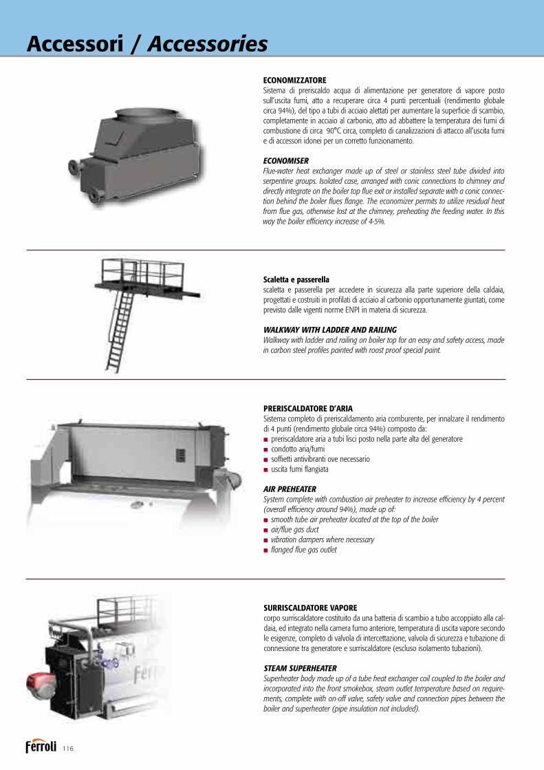
116
Accessori / AccessoriesECONOMIZZATORESistema di preriscaldo acqua di alimentazione per generatore di vapore posto sull’uscita fumi, atto a recuperare circa 4 punti percentuali (rendimento globale circa 94%), del tipo a tubi di acciaio alettati per aumentare la superficie di scambio, completamente in acciaio al carbonio, atto ad abbattere la temperatura dei fumi di combustione di circa 90°C circa, completo di canalizzazioni di attacco all’uscita fumi e di accessori idonei per un corretto funzionamento.
ECONOMISERFlue-water heat exchanger made up of steel or stainless steel tube divided into serpentine groups. Isolated case, arranged with conic connections to chimney and directly integrate on the boiler top flue exit or installed separate with a conic connec-tion behind the boiler flues flange. The economizer permits to utilize residual heat from flue gas, otherwise lost at the chimney, preheating the feeding water. In this way the boiler efficiency increase of 4-5%.
Scaletta e passerellascaletta e passerella per accedere in sicurezza alla parte superiore della caldaia, progettati e costruiti in profilati di acciaio al carbonio opportunamente giuntati, come previsto dalle vigenti norme ENPI in materia di sicurezza.
WALKWAY WITH LADDER AND RAILING Walkway with ladder and railing on boiler top for an easy and safety access, made in carbon steel profiles painted with roost proof special paint.
PRERISCALDATORE D’ARIASistema completo di preriscaldamento aria comburente, per innalzare il rendimento di 4 punti (rendimento globale circa 94%) composto da:n preriscaldatore aria a tubi lisci posto nella parte alta del generatoren condotto aria/fumin soffietti antivibranti ove necessarion uscita fumi flangiata
AIR PREHEATERSystem complete with combustion air preheater to increase efficiency by 4 percent (overall efficiency around 94%), made up of:n smooth tube air preheater located at the top of the boilern air/flue gas ductn vibration dampers where necessaryn flanged flue gas outlet
SURRISCALDATORE VAPOREcorpo surriscaldatore costituito da una batteria di scambio a tubo accoppiato alla cal-daia, ed integrato nella camera fumo anteriore, temperatura di uscita vapore secondo le esigenze, completo di valvola di intercettazione, valvola di sicurezza e tubazione di connessione tra generatore e surriscaldatore (escluso isolamento tubazioni).
STEAM SUPERHEATERSuperheater body made up of a tube heat exchanger coil coupled to the boiler and incorporated into the front smokebox, steam outlet temperature based on require-ments, complete with on-off valve, safety valve and connection pipes between the boiler and superheater (pipe insulation not included).

117
SISTEMA ALIMENTAZIONE MODULANTEIl sistema permette di mantenere un adeguato apporto di acqua in caldaia senza brusche interruzione del processo di ebollizione dovute a repentini cambi di livello all’interno del generatore. In questo modo si garantisce un elevato titolo di vapore, completo di: n regolatore configurabile universale n trasmettitore livello n sonda capacitiva n preamplificatore capacitanza n valvola pneumatica oppure elettrica e valvole di intercettazione n valvola di sfioro n valvola di sicurezza
BOILER MODULATING FEEDWATER CONTROLThis system allows to maintain constant the water flowrate at the boiler without interruptions to the boiling process, moreover it ensures a near constant volume of water in the boiler with an high steam title.System components: n Pneumatic or electric modulating valve n Bellow globe manual valve n Universal adaptable level regulator n Level transmitter n Capacitive level probe n Capacitance preamplifier n Stop valve n Piping connection
SECONDA POMPA DI ALIMENTAZIONESeconda pompa di alimentazione caldaia installata idraulicamente con tubazioni di collegamento e cablata elettricamente al quadro elettrico di caldaia. Il collegamento idraulico prevede due valvole di non ritorno e due valvole di intercettazione. A qua-dro sono previsti due selettori per prima o seconda pompa.
SECOND WATER FEEDING PUMPSecond automatic Feed Pump installed and wired with piping system to the boiler and electrical connection in electrical cable. The hydraulic connection is foreseen with two stop valves and two non return valves. On the electrical panel two selectors permit the first or second pump use.
SECONDO INDICATORE DI LIVELLOConnesso direttamente al generatore a mezzo di flange o manicotti filettati dipenden-temente del tipo di generatore per la rilevazione ottimale del livello caldaia.
SECOND LEVEL INDICATORDirectly connected to the boiler to permit the right level detection.
SISTEMA SPURGO AUTOMATICO DI FONDOIl sistema permette la rimozione automatica dei sali non disciolti che si depositano sul fondo caldaia ed è composto da: nvalvola defangatrice a sfera con attuatore pneumatico ntemporizzatore pausa lavoro nfiltro per elettrovalvola a 3 vie.
AUTOMATIC BLOW DOWN VALVEThe system permit to remove the not-solved salt from the boiler shell bottom.System components: n automatic pneumatic blow down valve with manual lever set-ting (on request) n timer regulator in electrical cable n filter for three way electro valve.
SISTEMA CONTROLLO SALINITÀ (TDS)Il sistema permette il controllo dei sali disciolti nell’acqua di caldaia rilevando in continuo il valore e spurgando, quando necessario, tramite la valvola pneumatica una porzione d’acqua sullo specchio superficiale Il sistema è composto da: nregolatore di spurgo a quadro elettrico nsonda di conducibilità in caldaia o camera di misura esterna nvalvola di spurgo elettrica o pneumatica nelettrovalvola nvalvola di intercettazione nconnessioni idrauliche
AUTOMATIC DESALTING CONTROL (TDS)This system permit the control of the salts dissolved in the boiler water reducing them when too high through the surface blow down.System components:n blow down regulator integrated in the electrical cable n surface conductivity probe inside the boiler body or measuring chamber n blow down control valve with pneu-matic or electrical actuator n electrovalve n stop valve n piping connection
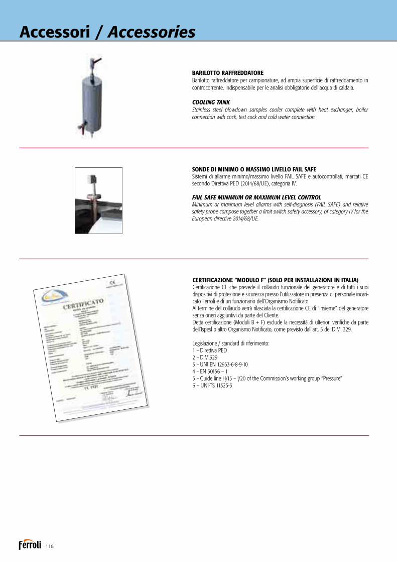
118
Accessori / Accessories
BARILOTTO RAFFREDDATOREBarilotto raffreddatore per campionature, ad ampia superficie di raffreddamento in controcorrente, indispensabile per le analisi obbligatorie dell’acqua di caldaia.
COOLING TANK Stainless steel blowdown samples cooler complete with heat exchanger, boiler connection with cock, test cock and cold water connection.
SONDE DI MINIMO O MASSIMO LIVELLO FAIL SAFESistemi di allarme minimo/massimo livello FAIL SAFE e autocontrollati, marcati CE secondo Direttiva PED (2014/68/UE), categoria IV.
FAIL SAFE MINIMUM OR MAXIMUM LEVEL CONTROLMinimum or maximum level allarms with self-diagnosis (FAIL SAFE) and relative safety probe compose together a limit switch safety accessory, of category IV for the European directive 2014/68/UE.
CERTIFICAZIONE “MODULO F” (SOLO PER INSTALLAZIONI IN ITALIA)Certificazione CE che prevede il collaudo funzionale del generatore e di tutti i suoi dispositivi di protezione e sicurezza presso l’utilizzatore in presenza di personale incari-cato Ferroli e di un funzionario dell’Organismo Notificato.Al termine del collaudo verrà rilasciata la certificazione CE di “insieme” del generatore senza oneri aggiuntivi da parte del Cliente.Detta certificazione (Moduli B + F) esclude la necessità di ulteriori verifiche da parte dell’Ispesl o altro Organismo Notificato, come previsto dall’art. 5 del D.M. 329.
Legislazione / standard di riferimento:1 – Direttiva PED2 – D.M.3293 – UNI EN 12953-6-8-9-104 – EN 50156 – 15 – Guide line H/15 – I/20 of the Commission’s working group “Pressure”6 – UNI-TS 11325-3

119
B.E.C.S.quadro elettrico di gestione generatori di vapore, di tipo industriale in cassetta metal-lica IP 54, a logica programmabile PLC, interfacciabile con un eventuale sistema di supervisione, comprendente: n PLC di comando e controllo completo di schede di input-output digitali ed analogiche nporta di comunicazione ethernet predisposta per interagire con il sistema di supervisione npannello operatore a touch-screen grafico con display LCD a colori da 5,7” nsoftware di gestione e controllo ninterruttore accensione caldaia ninterruttore accensione bruciatore npulsanti di ripristino sicurezze nspie di segnalazione.
B.E.C.S.Electronic control system design to manage and supervise all the boiler and boilers rooms functions and process. The internal core is based in the advanced Siemens CPU S7 300 instead the external operator interface is made up with an high perfor-mance colour touch panel. Main features are: n friendly and intuitive use for the final operator n customizable as for the specific installation exigencies n high reliability thanks to the primary brand components n multilanguage interfacen plant and boiler parameters modification and control n boiler logical control management (start-up sequences, boilers cascade functioning, nocturnal or stand-by periods etc.) n boiler alarms visualization and control with record possibility n main parameters record n main parameters visualization through dedicated graphics n access controlled by password n external interface trough dedicated gates.
B.E.C.S. FAIL SAFEQuadro elettrico di gestione generatori di vapore, esonerati 72 h, atto al lavoro in continuo senza interruzione del funzionamento generatore durante le fasi di verifica obbligatorie allo scadere delle 72 h. Quadro elettrico di tipo industriale in cassetta metallica IP 54, comprendente: n PLC di comando e controllo completo di schede di input-output digitali ed analogiche nporta di comunicazione ethernet predisposta per interagire con il sistema di supervisione npannello operatore a touch-screen grafico con display LCD a colori da 5,7” nsoftware di gestione e controllo ninterruttore accensione caldaia ninterruttore accensione bruciatore npulsanti di ripristino sicurezze nspie di segnalazione.
B.E.C.S. FAIL SAFESteam generator electrical control panel, 72 h exemption, designed for continuous operation without stopping the generator during the compulsory checks required when the 72 hours expire. Industrial electrical panel in IP 54 metal casing, comprising: n friendly and intuitive use for the final operator n customizable as for the specific installation exigencies n high reliability thanks to the primary brand components n multilanguage interfacen plant and boiler parameters modification and control n boiler logical control management (start-up sequences, boilers cascade functioning, nocturnal or stand-by periods etc.) n boiler alarms visualization and control with record possibility n main parameters record n main parameters visualization through dedicated graphics n access controlled by password n external interface trough dedicated gates.

120
Accessori / Accessories
Set accessori per l’ottenimento dell’esenzione da supervisione continua fino a 24 ore secondo UNI TS 11325-3, composto da:n n° 2 sonde di sicurezza livello minimo di tipo FAIL SAFE.n n° 1 sonda di livello massimo del tipo a conducibilità completa di regolatore.
Set of accessories for obtaining exemption from continuous supervision for up to 24 hours in accordance with UNI TS 11325-3, comprising:n 2 (two) failsafe minimum level safety probes.n 1 (one) conductivity maximum level probe, complete with
controller.
BMS 24H ITALIABMS 24H EUROPE

121
Set accessori per l’ottenimento dell’esenzione da supervisione continua fino a 72 ore secondo UNI TS 11325-3 e UNI EN 12953-6, composto da:nn° 1 sistema di controllo dell’acqua in caldaia (TDS) in conti-
nuo, costituito da: - regolatore per spurgo (230/115V – 50/60 Hz) - sonda di controllo conduttività - valvola di scarico sup. con attuatore pneumaticonn° 1 valvola defangatrice temporizzata con attuatore pneumaticonn° 2 sonde di sicurezza livello minimo di tipo FAIL SAFE.nn° 1 sonda di sicurezza livello massimo di tipo FAIL SAFE.nn° 1 CTE 72H, sistema di controllo a PLC necessario per la
procedura di gestione 72 h.
Set of accessories for obtaining exemption from continuous supervision for up to 72 hours in accordance with UNI TS 11325-3 and EN 12953-6, comprising:n1 (one) continuous boiler water control system (TDS), made
up of: - bleeding controller (230/115V – 50/60 Hz) - conductivity control probe - top drain valve with pneumatic actuatorn1 (one) timed sludge valve with pneumatic actuatorn2 (two) FAIL SAFE minimum level safety probes.n1 (one) FAIL SAFE maximum level safety probe. n1 (one) CTE 72H, PLC control system required for implemen-
ting the 72 h management procedure.
BMS 72H ITALIABMS 72H EUROPE

122
Accessori / AccessoriesVASO RACCOLTA CONDENSE - VRCSerbatoio di raccolta condensa, esecuzione verticale o orizzontale (a richiesta) a pressione atmosferica completo di:n regolatore di livello a galleggiante, per il reintegro dell’acqua di alimentazionen indicatore di livello acqua, in vetro, con rubinetti di intercettazionen isolamento con finitura in alluminio su richiesta.n serbatoio in AISI su richiesta
CONDENSIG VESSEL - VRCHorizontal or vertical condense and make-up water collecting tank at atmospheric pressure. Standard accessories and connections:n stainless steel float sphere and cock on make-up water siden level indicatorn insulation and aluminum cover (on request).n AISI stainless steel on request
DEGASATORE ATMOSFERICO - VRDDegasatore atmosferico, per la raccolta ed il preriscaldo, a mezzo vapore, dell’acqua di alimento del generatore, esecuzione orizzontale con corpo in acciaio al carbonio, completo di: ntermometro nfiltro Y nindicatore di livello acqua, in vetro, con rubi-netti di intercettazione nquadro elettrico (230 Vac/50 Hz/1ph/ + T+N) completo di regolatore livelli nn° 4 sonde (2 reintegro + 2 min/max livello) nelettrovalvola per alimentazioni acqua ncollegamenti elettrici nsistema di preriscaldo a vapore composto da: iniettore di vapore - valvola di regolazione - sistema termometrico - filtro - valvola di intercettazione.
ATMOSPHERIC DEAREATOR - VRDComplete with the steam pre-heating system the VRD is an atmospheric degassing unit at atmospheric pressure, designed to degasify the make-up cold water and the condense return. Standard accessories: n thermometer n Y filter n glass tube water level indicator n
electric panel complete with 4 limits conductive probes level management n n. 4 probes (2 recover + min level + max level) n recover electrovalve for make up water n electric connection n steam pre-heating system made up of: filter, steam injector, regulation valve, thermometric system, stop valve.
DEGASATORE TERMOFISICO - DGSTDegasatore termico presurizzato con pressione di lavoro 0.1-0.45 bar, progettato per degasare l’acqua di alimento di generatori di vapore composta dalle condense di ritorno e dall’acqua fredda di reintegro. Completo di torretta verticale di degasazione e avente le seguente caratteristiche:nmassima pressione di lavoro 0.45 barntemperatura acqua in uscita 105-110°Cnossigeno residuo <0.05 ppm
PRESSURIZED THERMAL DEGASSING DGST The DGST is an pressurized thermal degassing unit at positive pressure (0.1-0.45 bar), designed to degasify the make-up cold water and the condense return, com-plete with a vertical cylindrical degassing turret.Particularly building and functioning characteristics are: n max working pressure 0,45 barn deareator temperature 105-110°Cn residual oxygen < 0,05 ppm (with steady state unit)
Versione con soppalco (optional)Version with raised platform (optional)
Versione con soppalco (optional)Version with raised platform (optional)

123
SERBATOIO RAFFREDDATORE SPURGHI - BDVGruppo di raffreddamento “blow down vessel” atto a accogliere gli spurghi caldi di generatori di vapore, costruito in robusta lamiera in acciaio al carbonio, struttura verticale con fondi bombati di chiusura e con gambe di sostegno per fissaggio a terra, connessioni flangiate per collegamento alla rete degli spurghi ed alla rete fognaria per l’evacuazione dei fluidi spurgati delle caldaie; valvola di controllo temperatura termo azionata per immissione di acqua fredda per il raffreddamento dei fluidi spurgati dai generatori in modo tale che possano essere evacuati alla temperatura adeguata e consentita. Il sistema viene così composto: ncorpo in acciaio al carbonio nvalvola a sfera n filtro a Y nvalvola di ritegno npozzetto inox per regolatore n testata di sfiato ntermometro nvalvola a sfera di scarico naccessori d’uso nflange PN 16 n
pressione di progetto massima 1 bar n temperatura di progetto massima 120°C n
valvola termo azionata di regolazione temperatura per immissione acqua fredda per il raffreddamento degli spurghi di caldaia.
BLOW DOWN VESSEL - BDVAtmospheric blow down vessel complete with cooling water system to reduce the boiler waste fluids temperature before the drain into the waste water plant.The system is complete with: n steel vessel with self-porting structure n cold water injection system n set of inlet stop and check valves n pressure gauge n thermometer n Y filter n 15-50°C capillary self-activated thermo-regulator in INOX n drain valve n
design pressure max 1 bar n design temperature max 120°C.
SISTEMA DI TRATTAMENTO ACQUASistema di addolcimento acqua di alimento composto da:nn° 1/2 colonne in materiale composito, rivestita in PE rivestito in fibra di vetro e resina, completa di resine cationiche con specifiche alimentari a ciclo sodico nn° 1 valvola multivie per la gestione dei flussi nn° 1 centralina elettronica per la gestione del processo con logica volumetrica nn° 1 filtro dissabbiatore a bicchiere traspa-rente in poliammide completo di cartuccia in rete lavabile nn° 1 tino di stoccaggio salamoia in PE ad alta densità nn° 1 stazione di dosaggio prodotti composta da pompa dosatrice elettronica, serbatoio di stoccaggio prodotti in polietilene e valvola di iniezione e filtro di aspirazione nsale industriale in pastiglioni ncondizionante per acqua di caldaia.
BOILER WATER TREATMENTBoiler water treatment complete with:n Single or double composite material columns, PE layer with glass fiber and resin, supplied with cationic resins for alimentary use n Multiway valve n Volumetric electronic control system n Sand filters n Brinetank n Dosing system for PH and O2 control with polyethylene tank, dosing valve and injection valve n Industrial salt n
Conditioning products.
COLLETTORE VAPORECollettore vapore realizzato su specifica richiesta del cliente completo di attacco di connessione al generatore, di n. attacchi flangiati per spillamento vapore e di attacco per lo carico delle condense.CERTIFICATO CE AI SENSI DELLA DIRETTIVA EUROPEA 2014/68/UE.
STEAM HEADERSteam header realized and designed in accordance with customer necessities and complete with boiler connection, connection blank flanges and condensate draining. CE certified according to Directive 2014/68/UE.

124
Caldaia ad olio diatermico a tre giri effettivi di fumoDiathermic oil boiler with three flue passes
ELICOIL NO
Caldaie ad olio diatermico, del tipo a fascio tubiro elicoidale a uno o più principi, a fiamma passante e tre giri effettivi di fumo. Predisposte per funzionare in abbinamento a bruciatori ad aria soffiata a combustibile liquido (anche ad elevata densità) o gassoso. Gamma composta da 15 modelli con potenze utili da 117 a 5814 kW e produzione di vapore, in abbinamento con evaporatore serie EVA, da 166 a 8300 Kg/h.nPressione standard di progetto 10 barnTemperatura di impiego fino a 300°C per olii minerali e
350°C per olii sintetici, con un salto termico tra ingresso e uscita olio di ~40°C.
nA richiesta si possono prevedere caldaie con valori di tempe- ratura e salti termici differenti da quanto indicato sopra.nEsecuzione a due anelli concentrici inseriti in un corpo cilin-
drico in lamiera, a tenuta ermetica dei fumi. Il primo “anello” caratterizza il focolare lungo il quale si estende la fiamma; il secondo “anello” origina un percorso a tre giri di fumo che permette un ottimale sfruttamento dell’intera superficie di scambio favorendo l’impiego di bruciatori a basso NOx.
nFascio tubiero in acciaio al carbonio senza saldature.
Diathermic oil boilers featuring a helical tube bundle with one or more turns and three effective flue passes.Designed to ope-rate in combination with jet burners on liquid (including high density) or gas fuel. Range consisting of 15 models with useful heat outputs from 117 to 5814 kW and steam production, in combination with EVA series evaporator, from 166 to 8300 kg/h.
nStandard design pressure 10 barsnOperating temperature up to 300°C for mineral oils and
350°C for synthetic oils, with a temperature difference between oil inlet and outlet of around 40°C.
nUpon request boilers can be developed with different tempe-rature values and differences from those indicated above.
nConstruction with two concentric rings inside in a cylin-drical sheet metal body that’s tight to the flue gas. The first “ring” represents the furnace that the flame extends along; the second “ring” is the start of a three flue pass circuit that optimises use of the entire heat exchange surface, making it advantageous to use low NOx burners.
nTube bundle made from carbon steel without welding.

125
nAccess to the furnace is available through a burner door hinged to the boiler that can be opened from the right or the left; the door is lined on the inside with a suitably thick layer of refractory concrete and features a flame inspection opening and burner anchor plate.
nThe rear smokebox is bolted to the boiler, and lined on theinside with insulating concrete, and is fitted with cleanout door and attachment for the flue connection.
nThese modern-concept and high-efficiency generators have been designed and developed in compliance with European directive 2014/68/UE (PED) and the most recent national and European standards on pressurised recipients.
nThe boiler body is lined by a suitable layer of high density rock wool, protected by stainless steel plate (AISI 430); this reduces heat loss and improves overall efficiency.
nVertical version on request.
CERTIFICATIONCE mark in accordance with the following directivesPressure Equipment (2014/68/UE)Low Voltage (2014/35/UE)Electromagnetic Compatibility (2014/30/UE)
nL’accesso al focolare avviene attraverso un portellone portabruciatore fissato alla caldaia a mezzo cerniere che ne permet-tono l’apertura a destra ed a sinistra; il portellone è interna-mente rivestito con un adeguato spessore di cemento refratta-rio ed è dotato di spia fiamma e piastra porta bruciatore.
nLa cassa fumi posteriore è fissata alla caldaia mediante bul-loni, è internamente coibentata con cemento isolante ed è dotata di portina di pulizia ed attacco per il raccordo camino.
nDi moderna concezione e ad alto rendimento, questi genera-tori sono progettati e realizzati nel rispetto della Direttiva Europea 2014/68/UE (PED) e delle più recenti norme nazio-nali ed europee in materia di recipienti a pressione.
nIl corpo caldaia è rivestito da un adeguato strato di lana di roccia ad alta densità, protetto da lamierino inox (AISI 430); ciò permette di ridurre le dispersioni termiche migliorando il rendimento complessivo.
nVersione verticale a richiesta.
CERTIFICAZIONIMarcatura CE secondo le Direttive Apparecchi a pressione (2014/68/UE)Bassa Tensione (2014/35/UE) Compatibilità Elettromagnetica (2014/30/UE)
Isolamento portellone in cemento refrattario
Door insulated with refractory concrete
Portellone con aperturareversibile DX e SX
Door with reversible opening, R and L
Fascio tubiero elicoidale a due anelli
Two-ring helical tube bundle
Corpo caldaia interamente rivestitocon materassino in lana minerale
Boiler body completely lined with rock wool insulation
Scarico caldaia
Boiler drain

126
ELICOIL NODIMENSIONIDIMENSIONS
ELICOIL NO 100 200 320 400 500 640 800 1000 1300 1600 2000 2500 3000 4000 5000
DIMENSIONI A mm 890 1020 1020 1200 1200 1220 1330 1500 1630 1630 1800 2150 2150 2350 2690 DIMENSIONS B mm 1170 1295 1295 1485 1485 1495 1610 1775 1920 1920 2090 2440 2440 2640 2980 C mm 1560 1800 2120 2240 2360 2380 2980 3260 3520 3700 4080 4400 4620 5900 6480 D mm 1140 1240 1240 1340 1340 1345 1460 1600 1720 1720 1860 2170 2170 2370 2710 P mm 620 680 680 780 780 780 840 920 1000 1000 1080 1260 1260 1360 1530 Q mm 800 900 900 1060 1060 1060 1160 1320 1440 1440 1580 1900 1900 2060 2360 Mandata / Flow a1 DN 32 40 50 65 65 65 80 100 100 125 125 150 150 200 200 Ritorno / Return a2 DN 32 40 50 65 65 65 80 100 100 125 125 150 150 200 200 Scarico / Drain a3 mm 20 20 20 20 20 20 20 20 20 20 25 25 25 25 25 Uscita fumo / Flue outlet a4 Ø mm 200 250 250 300 300 300 350 350 400 400 450 500 500 600 700 Attacco bruciatore / Burner attachment fitting a5 Ø mm 220 220 220 240 240 240 270 300 360 360 360 430 430 430 430 Lunghezza min/max boccaglio
a5 mm 220/300 220/300 220/300 220/300 220/300 220/300 220/300 220/300 220/300 220/300 220/300 250/350 250/350 250/350 250/350 Length min/max draught tube burner Peso / Weight kg 700 950 1300 1600 1700 1800 2300 2900 3800 4200 5500 8500 9000 13000 15000
DATI TECNICITECHNICAL DATA
ELICOIL NO 100 200 320 400 500 640 800 1000 1300 1600 2000 2500 3000 4000 5000 Potenza nom. generatore / Heat output kW 116 232 372 465 581 744 930 1163 1512 1861 2326 2907 3489 4652 5815
Potenza focolare / Heat input kW 134 267 427 534 668 855 1069 1337 1738 2139 2673 3342 4010 5347 6684
Contropressione focolare / Furnace backpressure mbar 1,5 2,0 2,5 3,0 3,2 3,4 3,5 3,8 4,0 4,2 4,5 4,5 5,0 6,0 7,0
Contenuto olio / Oil content dm3 40 84 130 223 245 201 285 518 639 692 853 1592 1629 2464 2970
Perdita carico lato olio / Oil loss pressure 250°C m.c.l. 26 23 25 18 20 23 17 24 18 28 24 39 32 36 40
Salto termico / Fall of temperature °C 40 40 40 40 40 40 40 40 40 40 40 40 40 40 40
Portata pompa olio / Oil pump delivery m3/h 6,0 10,6 17,0 22,0 26,5 34,0 42,0 50,0 69,0 81,0 101,0 126,0 159,0 202,0 252,0
Prevalenza pompa olio / Pressure drop m.c.l. 45 49 48 45 45 45 40 46 42 50 49 60 56 58 58
Potenza elettrica pompa / Electrical power kW 3,0 4,0 5,5 5,5 7,5 7,5 7,5 11,0 11,0 15,0 18,5 30,0 30,0 37,0 55,0
ELICOIL NO 100-5000 Pressione max esercizio / Max working pressure 10 bar Pressione prova / Hydraulic test pressure 15 bar Temperatura progetto / Design temperature 350°C
Disegno N° 3936606/0Data ultima revisione 11/02/2011
Caldaia ad olio diatermico Diathermic oil boiler
ELICOIL NO 100-5000 Pressione max esercizio / Max working pressure 10 bar Pressione prova / Hydraulic test pressure 15 bar Temperatura progetto / Design temperature 350°C
Disegno N° 3936606/0Data ultima revisione 11/02/2011
Caldaia ad olio diatermico Diathermic oil boiler
ELICOIL NO 100-5000 Pressione max esercizio / Max working pressure 10 bar Pressione prova / Hydraulic test pressure 15 bar Temperatura progetto / Design temperature 350°C
Disegno N° 3936606/0Data ultima revisione 11/02/2011
Caldaia ad olio diatermico Diathermic oil boiler
Legenda1 Caldaia2 Porta3 Camera fumo4 Gruppo manometro/pressostato
Key1 Boiler2 Door3 Smokebox4 Pressure switch/manometer unit
ACCESSORI A CORREDOn Valvola flusso avviato allo scaricon Pressostato differenzialen Manometri di ingresso / uscita
ACCESSORIES SUPPLIEDn Mid-flow valves on the drainn Differential pressure switchn Inlet / outlet pressure gauges

127
ACCESSORI A RICHIESTA
nPreriscaldatore d’aria: è uno scambiatore fumi/aria che va inserito nel circuito fumi tra caldaia e camino. Consente recuperi di rendimento termico dell’ordine del 4%. Per tale soluzione è necessario disporre di un bruciatore tipo industriale con ventila-tore separato da montare a monte del preriscaldatore stesso.
nBruciatore: marchio e tipologia secondo le indicazioni del cliente.nPiastra porta bruciatore perforata secondo le indicazioni
del cliente.nGruppo pompa circolazione olio con 1 o 2 pompe, completo
di valvole, filtri, compensatori e manometro.nPannello strumenti completo di termoregolatori di lavoro e
di sicurezza.nQuadro elettrico di comando impianto (caldaia, pompa circo- lazione, vaso espansione ecc.).nPompa caricamento olio.nDegasatore olio: barilotto degasatore per l’eliminazione otti- male di aria in fase di carico e di esercizio del riscaldatore.nSerbatoio raccolta olio.nVaso espansione aperto.nVaso espansione pressurizzato.nB.E.C.S. (Boiler Electronic Configurable System): il sistema di
controllo B.E.C.S. è costituito da un PLC dotato di interfaccia operatore Touch Panel a colori di elevate prestazioni. Tramite l’interfaccia è possibile supervisionare il funzionamento dell’in-sieme Caldaia-Bruciatore-Impianto.
nTermoregolazione pneumatica con valvole di intercettazione.
In caso di collegamento con Evaporatore possono essere previsti a richiesta:nCollegamento idraulico tra ELICOIL NO ed Evaporatore.
ACCESSORIES AVAILABLE ON REQUEST
nAir preheater: a flue gas/air heat exchanger to be installedin the flue gas circuit between the boiler and the chimney. This increases thermal efficiency by around 4%. This solution requires an industrial burner with separate fan to be installed upstream of the preheater.
nBurner: brand and type chosen based on customer specifi-cations.
nPerforated burner plate based on customer specifications.nOil circulating pump assembly with 1 or 2 pumps, complete with valves, filters, compensators and pressure gauge.nInstrument panel complete with operating and safety tem-
perature controllers.nSystem electrical control panel (boiler, circulating pump,
expansion vessel etc.).nOil filling pump.nOil degasser: degasser tank for optimum air removal when
filling the heater and during operation.nOil collection tank.nOpen expansion vessel.nPressurised expansion vessel.nB.E.C.S. (Boiler Electronic Configurable System): the B.E.C.S. con-
trol system consists of a PLC fitted with high performance Touch Panel colour operator interface. The interface can be used to manage operation of the Boiler-Burner-Central Heating System.
nPneumatic temperature control with on-off valves.
If an evaporator is connected the following are available on request:nHydraulic connection between ELICOIL NO and
Evaporator.

128
Generatore di vapore indirettoIndirect steam generator
EVA
Generatore indiretto di vapore saturo a mezzo olio diatermico, esecuzione monoblocco, corpo in pressione in acciaio al carbo-nio, fascio tubiero di scambio estraibile con classica costruzione ad “U” in acciaio al carbonio oppure in inox AISI 304.Gamma composta da 15 modelli con producibilità da 166 kg/h a 8.300 kg/h.
nPressione standard di progetto 12 e 15 bar (a richiesta, pressioni superiori).nProduzione di vapore da 166 a 8.300 kg/h.nTestata di scambio in acciaio al carbonio flangiata sul corpo
dell’evaporatore con connessioni flangiate all’impianto.nCamera evaporante abbondantemente dimensionata con
un’ampia superficie di scambio per la produzione di vapore saturo di elevata qualità.
nLe dispersioni verso l’ambiente sono molto contenute graziead una adeguata coibentazione del corpo caldaia eseguita con uno strato di lana minerale ad alta densità e senza ponti termi-ci, protetta da un lamierino in acciaio inossidabile (AISI 430).
Indirect steam generator through hot oil, body made in carbon steel; “U” shape extractable coil exchanger made in carbon steel or AISI 304.The range includes 15 models from 166 kg/h up to 8.300 kg/h.
nStandard design pressure 12 and 15 bar (higher pressure on request).nSteam production from 166 kg/h up to 8.300 kg/h.nExchanging head in carbon steel flanged on the evaporator body with flanged connections to the plant.nLarge evaporating surface area and an amply sized eva-
porating chamber for the production of high quality dry saturated steam.
nLow casing leakage due to an adequate insulation of the boi-ler body with high density mineral wool; external protection with a stainless steel sheet (AISI 430).

129
nPressure parts welding are all performed by qualified per-sonnel and approved according to EN standards.
nDesign and construction in compliance with European Directive 2014/68/UE (PED) and the most recent European regulations on pressure vessels.
nEC assembly certificate in accordance to PED Directive.nWater side inspection allowed by man hole.
CERTIFICATIONCE mark in accordance with the following directives.Pressure Equipment (2014/68/UE)Low Voltage (2014/35/UE)Electromagnetic Compatibility (2014/30/UE)
nLe saldature delle parti in pressione sono tutte eseguite da personale qualificato IIS secondo norme EN.
nProgettati e realizzati nel rispetto della Direttiva Europea 2014/68/UE (PED) e delle più recenti norme nazionali ed europee in materia di recipienti a pressione.
nCertificazione come insieme secondo Direttiva PED.nL’ispezionabilità lato acqua è garantita da un passo uomo sul colmo del corpo in pressione.
CERTIFICAZIONIMarcatura CE secondo le Direttive Apparecchi a pressione (2014/68/UE)Bassa Tensione (2014/35/UE) Compatibilità Elettromagnetica (2014/30/UE)

130
EVADIMENSIONIDIMENSIONS
Legendaa1 Entrata olioa2 Uscita olioa3 Presa vaporea4 Scarico
Keya1 Inlet oila2 Outlet oila3 Steam outleta4 Drain
EVA 100 200 320 400 500 640 800 1000 1300 1600 2000 2500 3000 4000 5000
DIMENSIONI A mm 1220 1220 1320 1320 1420 1420 1650 1650 1750 1750 1850 1950 1950 2050 2150 DIMENSIONS B mm 1300 1300 1400 1400 1500 1500 1600 1600 1700 1700 1800 1900 1900 2000 2100 C mm 2580 2580 2583 2583 3248 3248 3968 3968 4671 4671 4494 5038 5038 4825 4833 D mm 1000 1000 1100 1100 1200 1200 1300 1300 1400 1400 1500 1600 1600 1700 1800 E* mm 1350 1350 1400 1755 1960 2360 2540 3040 3265 3765 3495 3330 3955 3500 2950 a1-a2 DN 50 50 50 50 65 65 80 80 100 100 125 150 150 200 200 a3 DN 40 40 50 50 65 65 65 65 80 80 100 125 125 150 150 a4 DN 25 25 25 25 25 25 25 25 40 40 40 40 40 40 40 Peso / Weight 12 bar kg 770 770 925 940 1405 1430 1990 2050 2720 2780 3100 3920 4000 4700 5640
DATI TECNICI / TECHNICAL DATA EVA 100 200 320 400 500 640 800 1000 1300 1600 2000 2500 3000 4000 5000
Potenza nominale / Nominal power kW 117 233 372 465 581 745 930 1163 1512 1862 2327 2909 3491 4652 5814 Produzione vapore / Steam production kg/h 166 332 532 664 830 1062 1328 1660 2158 2665 3320 4150 4980 6640 8300 Capacità totale / Total content dm3 910 910 1140 1130 1850 1840 2840 2830 4100 4080 4530 5950 5910 6200 7010 Capacità livello minimo / Min. level content dm3 620 620 720 710 1270 1260 1980 1970 2820 2800 3260 4450 4410 4590 4970 Contenuto olio / Oil content dm3 27,3 27,3 39,2 44,6 61,0 68,9 85,9 97,3 139,4 155 177 232 262 389 438 Perdita di carico lato olio / Oil loss pressure mbar 61,7 61,7 49,7 74,2 72,1 129 186,7 188,7 362 442 704 461 660 581 527
ACCESSORI A CORREDOn 1 gruppo pompa con valvole intercettazione e ritegnon 1 valvola intercettazione presa vaporen 1 valvola di scarico n 1 valvola sicurezza a mollan Pressostati di lavoron 1 pressostato di sicurezzan 1 manometro tipo Bourdon con rubinetto a tre vien 1 indicatori livello a riflessione con rubinettin 1 sistema controllo livelli ad elettrodin 1 quadro elettrico industriale
ACCESSORIES SUPPLIEDn 1 pump assembly with on-off and check valvesn 1 steam outlet on-off valven 1 lever-operated valve n 1 pring-loaded safety valven Operating pressure switchesn 1 safety pressure switchn 1 Bourdon pressure gauge with three-way valven 1 reflex level gauges with valvesn 1 electrode level control systemn 1 electrical panel

131
ACCESSORI A RICHIESTA
nSistema di alimentazione modulante per la gestione otti-male del livello acqua adatto in accoppiamento con economiz-zatore.
nSeconda pompa alimentazione stand-by con valvolame.nSecondo indicatore livello con rubinetti.nSistema per spurgo automatico di fondo dei depositi di
fanghi e di sali disciolti.nSistema controllo salinità (TDS) per la rilevazione dei sali
disciolti nell’acqua di esercizio.nBarilotto raffreddatore per prelievo campione acqua caldaia.nSonde di minimo livello FAIL SAFE.nB.E.C.S. (Boiler Electronic Configurable System): il sistema di
controllo B.E.C.S. è costituito da un PLC dotato di interfaccia operatore Touch Panel a colori di elevate prestazioni. Tramite l’interfaccia è possibile supervisionare il funzionamento dell’in-sieme Caldaia-Bruciatore-Impianto.
nVaso raccolta condense VRC.nSistema di trattamento acqua.nCollettore vapore.nBMS 24H per esercizio senza supervisione continua fino a 24 ore. nBMS 72H per esercizio senza supervisione continua fino a 72 ore.nCertificazione “MODULO F” presso l’utilizzatore.nDegasatore atmosferico VRD.nDegasatore termofisicio “DGST”.nSerbatoio raffreddatore spurghi “BDV”.
ACCESSORIES AVAILABLE ON REQUEST
nModulating supply system for optimum water level mana- gement in combination with an economiser.nSecond standby supply pump with valves.nSecond level gauge with valves.nSystem for automatically draining sludge and dissolved
salts that deposit on the bottom.nSalinity (TDS) control system that measures dissolved salts in the water.nCooling tank for sampling boiler water.nFAIL SAFE minimum level probes.nB.E.C.S. (Boiler Electronic Configurable System): the B.E.C.S.
control system consists of a PLC fitted with high performance Touch Panel colour operator interface. The interface can be used to manage operation of the Boiler-Burner-Central Heating System.
n“VRC” condensate collection vessel.n Water treatment system.n Steam manifold.nBMS 24H for up to 24 hours’ continuous unsupervised ope-ration.nBMS 72H for up to 72 hours’ continuous unsupervised ope-ration.n “VRD” atmospheric degasser.n “DGST” thermophysical degasser.n “BDV” drainage cooling tank.

132
Accessori / AccessoriesPRERISCALDATORE D’ARIASistema completo di preriscaldamento aria comburente, per innalzare il rendi-mento di 4÷5 punti (rendimento globale circa 92%) composto da:npreriscaldatore aria a tubi lisci posto nella parte alta del generatorencondotto aria/fuminsoffietti antivibranti ove necessarionuscita fumi flangiata
AIR PREHEATERSystem complete with combustion air preheater to increase efficiency by 4÷5 percent (overall efficiency around 92%), made up of:n smooth tube air preheater located at the top of the boilern air/flue gas ductn vibration dampers where necessaryn flanged flue gas outlet
GRUPPO POMPAIl gruppo pompa olio è indispensabile per la circolazione del fluido diatermico nell’impianto ed è composto da:n1 o 2 pompe circolazione olionmanometronfiltronvalvole flusso avviato su mandata e ritorno, in acciaio con tenuta a soffiettoncompensatori di dilatazione assiali su mandata e ritornoncollegamenti al riscaldatore
PUMP ASSEMBLYThe oil pump assembly is essential for the circulation of diathermic fluid in the system, and consists of:n 1 or 2 oil circulation pumpsn pressure gaugen filtern mid-flow valves on the outlet and return, made from steel with bellows sealn axial expansion compensators on the outlet and returnn connections to the heater
QUADRO ELETTRICOIl quadro elettrico è necessario per la gestione del riscaldatore in tutti gli aspetti operativi ed è inoltre in grado di gestire il funzionamento così come la potenza di n° 1 o in alternativa 2 pompe di circolazione olio, bruciatore, vaso di espan-sione, pompa di caricamento etc. ed è completo di:narmadio, grado di protezione IP 55ninterruttore generalensistemi di comando, segnalazione, funzionamento e blocconteleruttore di potenza per 1 pompa di circolazione olionpulsanti luminosi per segnalazione e riarmo manuale allarmi.
ELECTRICAL PANELThe electrical panel is used to manage all aspects of heater operation, inclu-ding management of 1 or 2 oil circulation pumps, burner, expansion vessel, filling pump etc., and comes complete with:n cabinet, index of protection IP 55n main switchn control, signal, operation and lockout systemsn contactor for 1 oil circulating pumpn illuminated buttons to signal alarms and for manual reset.
PANNELLO STRUMENTIIl pannello strumenti costituisce il sistema basilare per la gestione del riscal-datore per ciò che concerne la regolazione della temperatura e pressione con esclusione delle potenze degli accessori da accoppiare come pompa e brucia-tore. Il sistema è completo di:ntermoregolatore mandatantermoregolatore ritornontermoregolatore limite e sicurezza.
INSTRUMENT PANELThe instrument panel represents the basic system for managing the heater as concerns temperature and pressure control, excluding control of the related accessories such as pump and burner. The system comes complete with:n outlet temperature controllern return temperature controllern limit and safety temperature controller.
POMPA CARICAMENTO OLIOIl gruppo pompa di caricamento olio viene direttamente connesso al il vaso di espansione è serve per il primo caricamento dell’impianto secondo standard di tipo manuale.
OIL FILLING PUMPThe oil filling pump assembly is directly connected to the expansion vessel and is used to fill the system the first time, using a manual procedure.

133
DEGASATORE OLIOBarilotto degasatore per l’eliminazione ottimale di aria in fase di carico e di esercizio del riscaldatore.
OIL DEGASSERDegasser tank for optimum air removal when filling the heater and during operation.
SERBATOIO RACCOLTA OLIOVaso di raccolta olio a singola od il alternativa doppia parete con intercapedine d’aria, atto a contenere il contenuto dell’olio del riscaldatore e dell’impianto, costruzione in acciaio al carbonio verniciato, in esecuzione cilindrica orizzontale.
OIL COLLECTION TANKOil collection vessel, either single wall or double wall with air gap, designed to hold the heater and system oil content, made from painted carbon steel, with a horizontal cylindrical arrangement.
VASO ESPANSIONE APERTOVaso di espansione olio atmosferico, atto ad assorbire le dilatazioni termiche dell’olio in fase di esercizio, costruzione in acciaio al carbonio verniciato, in esecuzione cilindrica verticale completo di: nregolatore di livello n indicatore di livello nvalvola di ritegno.
OPEN EXPANSION VESSELOpen oil expansion vessel designed to absorb thermal expansion of the oil during operation, made from painted carbon steel, with a vertical cylin-drical arrangement, and complete with: n level controller n level gauge n check valve.
VASO ESPANSIONE PRESSURIZZATOVaso di espansione olio pressurizzato, atto ad assorbire le dilatazioni termiche dell’olio in fase di esercizio, costruzione in acciaio al carbonio verniciato, in esecuzione cilindrica verticale completo di:nn° 3 pressostati nn° 1 manometro nn° 1 rubinetto nn° 1 termometro nn° 2 valvole non ritorno nn° 1 Valvola a flusso avviato nn° 1 regolatore di livellonn° 1 indicatore di livello nn° 1 valvola di sicurezza.
PRESSURISED EXPANSION VESSELPressurised oil expansion vessel designed to absorb thermal expansion of the oil during operation, made from painted carbon steel, with a vertical cylindrical arrangement, and complete with:n 3 pressure switches n 1 pressure gauge n1 valve n1 thermometer n2 non return valves n1 mid-flow valve n1 level controller n1 level gauge n1 safety valve.
B.E.C.S.quadro elettrico di gestione generatori di vapore, di tipo industriale in cassetta metallica IP 54, a logica programmabile PLC, interfacciabile con un eventuale sistema di supervisione, comprendente: nPLC di comando e controllo comple-to di schede di input-output digitali ed analogiche nporta di comunicazione ethernet predisposta per interagire con il sistema di supervisione npannello operatore a touch-screen grafico con display LCD a colori da 5,7” nsoftware di gestione e controllo ninterruttore accensione caldaia ninterruttore accensione bruciatore npulsanti di ripristino sicurezze nspie di segnalazione.
B.E.C.S.Electronic control system design to manage and supervise all the boiler and boilers rooms functions and process. The internal core is based in the advanced Siemens CPU S7 300 instead the external operator interface is made up with an high perfor-mance colour touch panel. Main features are: n friendly and intuitive use for the final operator n customizable as for the specific installation exigencies n high reliability thanks to the primary brand components n multilanguage interface n plant and boiler parameters modification and control n boiler logical control management (start-up sequences, boilers cascade functioning, nocturnal or stand-by periods etc.) n boiler alarms visualization and control with record possibility n main parameters record n main parameters visualization through dedicated graphics n access control-led by password n external interface trough dedicated gates.
TERMOREGOLAZIONE PNEUMATICATermoregolazione pneumatica per la regolazione della pressione o della temperatura nel corpo scaldante secondario come evaporatore o scambia-tore olio acqua completa di:nvalvola a tre vie in ghisa nattuatore pneumatico nn° 3 valvole flusso avviato con tenuta a soffietto nregolatore di pressione o temperatura nfiltro riduttore per aria compressa
PNEUMATIC TEMPERATURE CONTROLPneumatic temperature control device for managing pressure or tempera-ture in the secondary heating body, such as evaporator or oil-water heat exchanger, complete with:n cast-iron three-way valve n pneumatic actuator n 3 mid-flow valves with bellows seal npressure or temperature controller ncompressed air reducer filter

134
Caldaia per acqua calda per combustibili solidiSolid fuel boiler for hot water production
FOREST
Il modello FOREST è una caldaia per acqua calda a combustibili solidi, specifica per trucioli e pellets di legno.Struttura mista a intercapedine e tubi d’acqua. La griglia di alimen-tazione consente un apporto di combustibile dosato in continuo anche per materiale grossolano e garantendo il rispetto delle attuali norme in materia di emissioni per legno non trattato. Gamma composta da 6 modelli con potenze utili da 116 kW a 800 kW con marcia di tipo ON - OFF e possibilità di taratura inferiore alla nominale.
CARATTERISTICHE PRINCIPALInPressione standard di progetto 2 bar nAlimentazione a coclea di nostra concezione che nasce da
un progetto unico caldaia-focolare meccanico.nSottogriglia diviso in comparti stagni per una adduzione dif- ferenziata dell’aria comburente.nCamera di combustione molto ampia. Rivestita completa-
mente di mattoni refrattari per raggiungere elevate tempera-ture di combustione. Esternamente raffreddata con pareti ad intercapedini d’acqua per eliminare ogni dispersione di calore verso l’esterno.
nCombustione in due stadi, con gassificazione in griglia e rapporto aria primaria/aria secondaria sopragriglia variabile.
The FOREST model is a hot water boiler operating on solid fuel, specifically wood shavings and pellets.Mixed double-shell and water tube structure. The fuel supply grate ensures continuously metered fuel feed even for coarse material, guaranteeing compliance with current emission standards for untreated wood.Range featuring 6 models with useful heat output from 116 kW to 800 kW and ON - OFF operation; output can also be calibra-ted below the design value.
MAIN FEATURESnStandard design pressure 2 bar nOur specially conceived screw feed assembly, the result of a single boiler-mechanical burner design.nUndergrate divided into sealed compartments for differen-
tiated combustion air feed.n Very wide combustion chamber. Lined with refractory
bricks and featuring a brick vault at the top to allow high com-bustion temperatures. Externally cooled with water between the walls to eliminate all heat losses to the outside.
nTwo-stage combustion, with grate-level gasification and a wide range of primary air/secondary air ratios above the grate according to the type of fuel used.

135
n High quality, externally-insulated brick refractory cladding.nTube nest and geometry of flue gas route guarantees mini- mum cleaning operations and complete accessibility. Large doors to access the grate level and removing the ash;nTemperature control system for automatically activating
the discharge screw and fire safety system;nHigh combustion efficiency. With pellet fuel the efficiency
may exceed 90%.
CERTIFICATIONCE Mark in accordance with following Directives: Machinery (2006/42 EEC)Low Voltage (2014/35/UE)Electromagnetic Compatibility (2014/30/UE)
nRivestimento refrattario, del tipo in mattoni isolati verso l’esterno, è di elevato standard.
nFascio tubiero e geometria del percorso fumi tale da garantire un numero minimo di interventi di pulizia ed una accessibilità totale con ampie porte al piano di griglia per la rimozione delle ceneri.
nSistema termostatico per avanzamento automatico coclea e predisposizione antincendio.nElevati rendimenti di combustione. Con combustibile pel-
lets è possibile superare rendimenti del 90%.
CERTIFICAZIONIMarcature CE secondo le Direttive: Macchine (2006/42 CEE)Bassa Tensione (2014/35/UE) Compatibilità Elettromagnetica (2014/30/UE)
CORPO CALDAIA / BOILER BODY1.1 CAMERA A CALORE RADIANTE / RADIANT HEAT CHAMBER1.2 PORTA CAMERA COMBUSTIONE / COMBUSTION CHAMBER DOOR1.3 VOLTO DI RINVIO FUMI / FLUE GAS REBOUND VAULT1.4 PORTA DI PULIZIA SUPERFICIE FASCIO TUBIERO TUBE NEST SURFACE CLEANING DOOR1.5 PORTA DI PULIZIA BASE FASCIO TUBIERO / TUBE NEST BASE CLEANING DOOR1.6 PORTINA ANTISCOPPIO / EXPLOSION-PROOF DOOR1.7 FASCIO TUBIERO / TUBE NEST1.8 SETTI DEFLETTORI FUMI / FLUE GAS DEFLECTOR BAFFLES1.9 CONDOTTO USCITA FUMI / FLUE1.10 VENTILATORE ARIA COMB. SECONDARIA / SECONDARY COMB. AIR FAN1.11 UGELLI ARIA SOPRAGRIGLIA / OVERGRATE AIR NOZZLES1.12 SPIA CONTROLLO COMBUSTIONE / COMBUSTION CONTROL LIGHT1.13 DEPRIMOMETRO E MANOMETRO / VACUOMETER AND MANOMETER
ACCESSORI OPZIONALI / OPTIONAL ACCESSORIESREGOLATORE DI TIRAGGIO CON INVERTER SU ASP. FUMI / DRAUGHT REGULATOR
BASAMENTO / BED2.1 VENTILATORE ARIA COMB. PRIMARIA / PRIMARY COMBUSTION AIR FAN2.2 PORTA PULIZIA SOTTOGRIGLIA ESTERNA / EXTERNAL UNDERGRATE CLEANING DOOR
2.3 PORTA PULIZIA SOTTOGRIGLIA INTERNA INTERNAL UNDERGRATE CLEANING DOOR2.4 GRIGLIA INTERNA / INTERNAL GRATE2.5 GRIGLIA ESTERNA / EXTERNAL GRATE
FOCOLARE MECCANICO / MECHANICAL FURNACE3.1 MOTOVARIATORE / ADJUSTABLE SPEED MOTOR GEAR3.2 ALIMENTATORE A COCLEA / FEED SCREW3.3 TRAMOGGIA CON CONTROLLO DI LIVELLO / HOPPER WITH LEVEL CONTROL3.4 RASCHIATORE MOTORIZZATO / MOTORISED SCRAPER3.5 SICUREZZA ANTIRITORNO DI FIAMMA / ANTI BACK-FIRING SYSTEM
QUADRO ELETTRICO / ELECTRICAL PANEL4.1 CASSETTA QUADRO ELETTRICO MONTATA A BORDO CALDAIA ELECTRICAL PANEL CABINET FITTED ON THE BOILER - CABLAGGIO DI TUTTE LE UTENZE BORDO MACCHINA - WIRING FOR ALL THE DEVICES ON THE UNIT - TEMPERATURA DIGITALE H2O MANDATA E FUMI - DIGITAL H2O OUTLET AND FLUE GAS TEMPERATURE DISPLAY - TERMOSTATO DI LAVORO / WORKING THERMOSTAT - TERMOSTATO DI SICUREZZA / SAFETY THERMOSTAT

136
FORESTDIMENSIONIDIMENSIONS
DATI TECNICITECHNICAL DATA
FOREST 100 150 250 400 600 700 Potenzialità generatore / Generator heat input W=30% kW 116 174 290 465 700 800
Potenzialità focolare / Heat input W=30% kW 135 202 336 539 812 928
Contenuto d’acqua / Water content dm3 398 456 674 745 1022 1132
Superficie di scambio (totale) / Heat exchange surface (total) m2 10,9 14,5 21,1 24,5 38,4 49,2
Volume camera combustione / Combustion chamber volume m3 0,41 0,48 0,69 0,83 1,11 1,25
Lato fumi / Smoke side ∆p mbar 0,8 1,1 1,4 2,0 2,4 2,6
Lato acqua / Water side ∆p mbar 100 120 120 160 200 220
FOREST 100 150 250 400 600 700
DIMENSIONI A mm 1398 1498 1860 1860 2210 2450 DIMENSIONS B mm 1209 1209 1209 1209 1274 1274 C mm 1368 1468 1583 1803 1918 1918 D mm 790 790 790 790 820 820 E mm 675 725 745 745 805 805 F mm 338 338 338 338 382 382 G mm 1370 1370 1370 1370 1353 1353 H mm 2898 2998 3360 3360 3710 3950 L mm 4533 4683 4818 5038 5243 5243 M mm 2700 2700 2700 2700 2800 2800 a1-a2 DN 50 65 80 80 100 100 a3 mm 200 200 250 250 300 300 a4 mm 270x170 270x170 270x170 270x170 270x170 270x170 Peso caldaia / Boiler weight kg 1230 1400 1880 2050 2720 3015 Peso basamento / Boiler bed weight kg 410 460 530 560 680 680 Peso tramoggia / Hopper weight kg 210 210 210 210 210 210 Peso alimentatore / Feeder weight kg 130 130 130 130 210 210
DIVISIONE CALDAIE INDUSTRIALI
Key1 Boiler body2 Boiler bed3 Hopper (cap. 0.65 m3) *4 Mechanical furnace5 Boiler electrical control panel
a1 Outleta2 Returna3 Flue connectiona4 Hopper loadinga5 Combustion chamber door
* If only pellets are used as fuel, a pyramid-shaped hopper can be used without motor-driven scraper.
Legenda1 Corpo Caldaia2 Basamento3 Tramoggia (cap. 0,65 m3) *4 Focolare meccanico5 Quadro elettrico comando caldaia
a1 Mandataa2 Ritornoa3 Attacco caminoa4 Caricamento tramoggiaa5 Porta camera combustione
* Nel caso di impiego di soli pellets si può adottare una tramoggia tronco piramidale senza raschiatore motorizzato.

137
ACCESSORI A RICHIESTA
nPotenza termica modulata in continuo: permette di ridurre la potenzialità bruciata dal 100 fino al 50%, riducendo al minimo gli spegnimenti della caldaia. La sonda di mandata agisce sul regolatore a logica programmabile che modifica la velocità della coclea di alimentazione e le portate d’aria com-burente mediante inverter.
nRegolatore di tiraggio: mantiene costante il tiraggio in camera di combustione tramite un rilevatore e una valvola a farfalla motorizzata sul condotto di by-pass della batteria mul-ticiclonica oppure inverter sull’aspiratore fumi.
COMBUSTIBILI COMPATIBILInScarti della lavorazione del legno e del sughero non trattati.nBiomasse (Scarti vegetali di attività agricole, forestali e di prima
lavorazione dei prodotti agroalimentari).nPellets di legno.nMassima percentuale di ceneri sul combustibile secco: 2%.
GRANULOMETRIA MASSIMA AMMESSA, UMIDITÀ DEL COMBUSTIBILE, GARANZIE SUL PROCESSO DI COMBU-STIONE E SULLE EMISSIONI AL CAMINO, saranno definite su specifiche richieste a livello contrattuale.
ACCESSORIES AVAILABLE ON REQUEST
nContinuous heat output modulation: allows the heat input to be reduced continuously from 100% to 50% minimising the number of boiler shut-downs. A programmable logic controller connected to the water outlet temperature probe varies the rota-tion speeds respectively of the fuel feed screw and the combu-stion air fans using inverters that drive the corresponding motors.
nDraught regulator: this keeps the draught in the com-bustion chamber constant, using a sensor device and a motor-driven throttle valve on the centrifugal dust separator assembly bypass duct or the flue gas exhaust inverter.
COMPATIBLE FUELSnWaste from the processing of untreated wood and cork.nBiomass (plant waste from agricultural and forestry activities and
from the first processing phase of agricultural and food products).nWood pellets.nMaximum amount of dry fuel ash: 2%.
MAXIMUM GRAIN SIZE ALLOWED, FUEL MOISTURE CONTENT, GUARANTEES ON THE COMBUSTION PROCESS AND EMISSIONS, will be defined contractually, based on specific requirements.

138
Caldaia mista a intercapedine e tubi d’acqua per combustibili solidi, a griglia fissaCofferdam and water tubes mixed boiler, for solid fuels, with fixed grate
WOOD MATIC S
Il modello WOOD MATIC S è una caldaia a intercapedine e tubi d’acqua, concepita appositamente per combustibili solidi, con struttura tubiera. Caldaia a combustibile solido a griglia fissa, ido-nea per la combustione di biomassa, scarti della lavorazione del legno non trattato. Le particolari soluzioni a livello di alimenta-zione e di griglia consentono un apporto di combustibile dosato in continuo anche per materiale grossolano e garantiscono il rispetto delle attuali norme in materia di emissioni.Gamma composta da modelli 9 modelli con potenze utili da 174 kW a 2.326 kW, con marcia di tipo ON - OFF e possibilità di taratura inferiore alla nominale.
CARATTERISTICHE PRINCIPALInPressione standard di progetto 2 bar nAlimentatore a coclea di nostra concezione che nasce da un progetto unico caldaia-focolare meccanico.nSottogriglia diviso in comparti stagni per una adduzione dif- ferenziata dell’aria comburente.nCamera di combustione molto ampia e completamente
secca, dotata di volta di riverbero e percorso invertito dei fumi per una ottimale essiccazione del combustibile umido.
The WOOD MATIC S is a double-shell and water-tube boiler designed specifically for solid fuels, with special tube structure.Fixed grate solid fuel boiler, ideal for biomass combustion, untreated wood processing scrap. The particular fuel feed and grate solutions enable a constant supply of fuel to be delivered, even when using coarse material, and ensure compliance with the current emission standards.Range consisting of models 9 models with useful heat outputs from 174 kW to 2,326 kW, featuring ON - OFF operation and the possibility to be calibrated below rated output.
MAIN FEATURESnStandard design pressure 2 bar nOur specially conceived screw feed assembly, the result of a single boiler-mechanical burner design.nUndergrate divided into sealed compartments for differen-
tiated combustion air supply.nLarge and completely dry combustion chamber with
rebound vault and reverse flue gas flow for optimum drying of damp fuel.

139
nTwo-stage combustion, with grate-level gasification and awide range of primary air/secondary air ratios according to the type of fuel used. Secondary air injected by independent high-turbulence system.
nHigh-quality mixed cast and brick refractory cladding according to the zone, tube bundle and shape of flue gas path guarantees minimum cleaning operations and complete accessibility through the side doors.
nThe bed that supports the boiler houses the combustion chamber, and is completely lined by special bricks for high-temperature combustion; it is cooled by water tubes to elimi-nate the heat radiated from the outer walls.
nThermostatic system for automatic screw advance and optional fire safety device.
nHigh combustion efficiency, normally above 85%.
CERTIFICATIONCE Mark in accordance with following Directives: Machinery (2006/42 EEC)Low Voltage (2014/35/UE)Electromagnetic Compatibility (2014/30/UE)
nCombustione in due stadi, con gassificazione in griglia e rapporto aria primaria/aria secondaria variabile in un ampio campo a seconda del combustibile impiegato. Aria secondaria iniettata con sistema ad alta turbolenza, indipendente.
nRivestimento refrattario, del tipo misto in gettata e in mat-toni a seconda delle diverse zone, è di elevato standard fascio tubiero e geometria del percorso fumi tali da garantire un numero minimo di interventi di pulizia e accessibilità totale attraverso le porte laterali.
nIl basamento che sostiene la caldaia alloggia la camera di com-bustione ed è completamente rivestito di mattoni per una combu-stione ad elevate temperature, ma è raffreddato a intercapedine d’acqua per annullare il calore irraggiato dalle pareti esterne.
nSistema termostatico per avanzamento automatico coclea e predisposizione antincendio.nElevati rendimenti di combustione, normalmente superiori
all’85%.
CERTIFICAZIONIMarcature CE secondo le Direttive: Macchine (2006/42 CEE)Bassa Tensione (2014/35/UE) Compatibilità Elettromagnetica (2014/30/UE)
CORPO CALDAIA / BOILER BODY - 1.1 CAMERA A CALORE RADIANTE / RADIANT HEAT CHAMBER 1.2 VOLTO DI RINVIO FUMI / FLUE GAS REBOUND VAULT 1.3 PORTA DI PULIZIA FASCIO TUBIERO / TUBE NEST CLEANING DOOR 1.4 PORTA DI PULIZIA VOLTINO / FURNACE ARCH CLEANOUT DOOR 1.5 PORTINA ANTISCOPPIO / EXPLOSION-PROOF DOOR 1.6 FASCIO TUBIERO / TUBE NEST 1.7 SETTI DEFLETTORI FUMI / FLUE GAS DEFLECTOR BAFFLES 1.8 CONDOTTO USCITA FUMI / FLUE 1.9 MANOMETRO CON RUBINETTO DI PROVA / PRESSURE GAUGE WITH TEST COCK 1.10 DEPRIMOMETRO / VACUOMETER 1.11 CONTROLLO TEMPERATURA DI COMBUSTIONE / COMBUSTION TEMPERATURE CONTROL
ACCESSORI OPZIONALI / OPTIONAL ACCESSORIES - 1.12 REGOLATORE DI TIRAGGIO CON INVERTER SU ASP. FUMI / DRAUGHT REGULATOR 2.10 BRUCIATORE PILOTA DI ACCENSIONE / PILOT BURNER 2.11 MODULAZIONE IN CONTINUO DELLA PORTATA COMBUSTIBILE E DELL’ARIA COMBURENTE / CONTINUOUS MODULATION OF THE FUEL AND COMBUSTION AIR FLOW-RATE
BASAMENTO / BED - 2.1 VENTILATORE ARIA COMB. PRIMARIA / PRIMARY COMBUSTION AIR FAN 2.2 VENTILATORE ARIA COMB. SECONDARIA / SECONDARY COMBUSTION AIR FAN 2.3 PORTA PULIZIA CAMERA COMBUSTIONE / COMBUSTION CHAMBER CLEANING DOOR 2.4 PORTA PULIZIA SOTTOGRIGLIA INTERNA / INTERNAL UNDERGRATE CLEANING DOOR 2.5 PORTA PULIZIA SOTTOGRIGLIA ESTERNA / EXTERNAL UNDERGRATE CLEANING DOOR 2.6 GRIGLIA INTERNA / INTERNAL GRATE 2.7 GRIGLIA ESTERNA / EXTERNAL GRATE 2.8 UGELLI ARIA SECONDARIA / SECONDARY AIR NOZZLES2.9 SPIA CONTROLLO COMBUSTIONE / COMBUSTION INSPECTION OPENING
FOCOLARE MECCANICO / MECHANICAL FURNACE - 3.1 MOTOVARIATORE / ADJUSTABLE SPEED MOTOR GEAR 3.2 ALIMENTATORE A COCLEA / FEED SCREW 3.3 TRAMOGGIA CON CONTROLLO DI LIVELLO / HOPPER WITH LEVEL CONTROL 3.4 RASCHIATORE MOTORIZZATO / MOTORISED SCRAPER 3.5 SICUREZZA ANTIRITORNO DI FIAMMA / ANTI BACK-FIRING SYSTEM

140
DIVISIONE CALDAIE INDUSTRIALI
WOOD MATIC SDIMENSIONIDIMENSIONS
Key1 Boiler body2 Boiler bed3 Hopper4 Mechanical furnace
a1 Outleta2 Returna3 Flue connectiona4 Hopper loadinga5 Pilot burner connection
Legenda1 Corpo Caldaia2 Basamento3 Tramoggia4 Focolare meccanico
a1 Mandataa2 Ritornoa3 Attacco caminoa4 Caricamento tramoggiaa5 Attacco bruciatore pilota
DATI TECNICITECHNICAL DATA
WOOD MATIC S 800 1000 1200 1500 2000 2500 Potenzialità generatore / Generator heat input kW 930 1163 1395 1768 2326 2907
Potenzialità focolare / Heat input kW 1094 1368 1641 2080 2736 3420
Contenuto d’acqua / Water content dm3 1691 1786 1904 2698 2755 3300
Superficie di scambio (totale) / Heat exchange surface (total) m2 57,8 68,6 79,4 102,7 128,3 160,4
Volume camera combustione / Combustion chamber volume m3 2,830 3,048 3,910 4,539 6,956 6,956
Lato fumi / Smoke side ∆p mbar 2,7 3,2 3,3 3,5 4,9 5,2
Lato acqua / Water side ∆p mbar 300 350 400 400 480 500
WOOD MATIC S 800 1000 1200 1500 2000 2500
DIMENSIONI A mm 1828 1937 2007 2204 2420 2590 DIMENSIONS B mm 1520 1600 1600 1730 1730 1730 C mm 2473 2473 2808 2900 3500 3500 D mm 970 970 980 980 990 990 E mm 900 900 900 900 975 975 F mm 1000 1000 1000 1000 1000 1000 G mm 1360 1360 1360 1360 1388 1388 H mm 4412 4521 4644 4841 5172 5342 L mm 6243 6243 6588 6680 7365 7365 M mm 3220 3300 3300 3430 3430 3430 N mm 1200 1200 1200 1200 1200 1200 P mm 1584 1584 1637 1637 1752 1752 a1-a2 DN 125 125 125 125 150 150 a3 mm 350 350 400 400 500 600 a4 mm 270x170 270x170 270x170 270x170 270x170 270x170 a5 lungh. boccaglio / draught tube length mm 280-350 280-350 280-350 280-350 280-350 280-350 a5 Ø boccaglio max / max draught tube dia. mm 155 155 155 155 155 155 Peso caldaia / Boiler weight kg 3280 3900 4180 4940 5890 6300 Peso basamento / Boiler bed weight kg 4080 4290 4980 5320 5610 5820 Peso tramoggia / Hopper weight kg 340 340 340 340 340 340 Peso alimentatore / Feeder weight kg 250 250 360 360 410 410
DIVISIONE CALDAIE INDUSTRIALI

141
ACCESSORI A RICHIESTA
nPotenza termica modulata in continuo: permette di ridur-re la potenzialità bruciata dal 100 fino al 50%, riducendo al minimo gli spegnimenti della caldaia. La sonda di mandata agisce sul regolatore a logica programmabile che modifica la velocità della coclea di alimentazione e le portate d’aria com-burente mediante inverter.
nRegolatore di tiraggio: mantiene costante, il tiraggio incamera di combustione tramite un rilevatore ed una valvola a farfalla motorizzata sul condotto di by-pass della batteria multiciclonica oppure inverter sull’aspiratore fumi.
nBruciatore di accensione o pilota: per la prima accensionedel combustibile (indispensabile per materiali con elevata umidità), ad una sola fiamma può essere alimentato da gasolio o gas metano. Inserimento ed arretramento in caldaia può essere automatizzato mediante sistema pneumatico.
nAnalizzatore con controllo in continuo: lettura su displaydi: CO - O2, temperatura fumi camino (obbligatori secondo DM 05/02/98 per potenze superiori a 1 MW).
nSistema di registrazione dati sulle emisssioni fumi al camino “Trend View”: software di acquisizione dati in conti-nuo. I dati raccolti possono essere ordinati in formato tabellare secondo quanto richiesto dal D.Lgs. 152/06.
nSistema pulizia ad onda d’urto SBS: il sistema è compostoda una serie di soffiatori ad onda d’urto applicati sulla struttura caldaia, e da un temporizzatore. Le polveri residue vengono trasportate dal flusso dei fumi e vengono decantate del siste-ma di filtrazione a valle della caldaia. Il sistema funziona con caldaia in marcia.
nRicircolo fumi in camera di combustione per abbatti-mento NOx: il sistema permette di completare la combustio-ne con una temperatura costante e più bassa rispetto ad una combustione senza il ricircolo.
ACCESSORIES AVAILABLE ON REQUEST
nContinuous heat output modulation: allows the heat input to be reduced continuously from 100% to 50% minimi-sing the number of boiler shut-downs. A programmable logic controller connected to the water outlet temperature probe varies the rotation speeds respectively of the fuel feed screw and the combustion air fans using inverters.
nDraught regulator: this keeps the draught in the combu-stion chamber constant, using a sensor device and a motor-driven throttle valve on the centrifugal dust separator assem-bly bypass duct or the flue gas exhaust inverter.
nIgnition or pilot burner: allows automatic initial ignition of the fuel (essential for materials with a high moisture content), single flame, operating on oil or natural gas. A pneumatic system automatically controls its entry into and return out of the boiler.
nAnalyser with continuous control: reading on display ofCO - O2, flue gas temperature (required by legislation for heat outputs exceeding 1 MW).
n“Trend View” system for recording data on flue gasemissions: software for continuous data acquisition. The data can be processed the data in table form (as required by certain legislation).
nSBS shockwave cleaning system: the system is made up of a series of shockwave blowers fitted on the boiler structure, and a timer. The residual dust from combustion removed from the tube bundle is carried by the flue gas and decants in the filtration system downstream of the boiler. The system works with the boiler operating.
nFlue gas recirculation in the combustion chamber forNOx reduction: the system allows combustion to occur at a constant and lower temperature than combustion without recirculation.
COMBUSTIBILI COMPATIBILI TIPOLOGIA
nRifiuti della prima e seconda lavorazione del legno e del sughero non trattati.
nBiomasse (Scarti vegetali di attività agricole, forestali, di prima lavorazione dei prodotti agroalimentari, sanse esauste, vinac-cioli, farina di vinaccioli, residui di frutta, buccette e altri residui vegetali).
nPellets di legno.nMassima percentuale di ceneri sul combustibile secco: 2%.
GRANULOMETRIA MASSIMA AMMESSA, UMIDITÀ DEL COMBUSTIBILE, GARANZIE SUL PROCESSO DI COMBUSTIONE E SULLE EMISSIONI AL CAMINO, saranno definite su specifiche richieste a livello contrattuale.
COMPATIBLE FUEL TYPES
nWaste from the first and second processing of untreated wood and cork.nBiomass (plant waste from agricultural and forestry activities
and from the first processing of agricultural and food pro-ducts, depleted pomace, grape seed, grape seed flour, fruit residues, peels and other plant residues).
nWood pellets.nMaximum amount of dry fuel ash: 2%.
MAXIMUM GRAIN SIZE ALLOWED, FUEL MOISTURE CONTENT, GUARANTEES ON THE COMBUSTION PROCESS AND EMISSIONS, will be defined contractually, based on specific requirements.

142
Caldaia mista a intercapedine e tubi d’acqua per combustibili solidi, a griglia mobileCofferdam and water tubes mixed boiler, for solid fuels, with mobile grate
WOOD MATIC SGM
Il modello WOOD MATIC SGM è una caldaia a intercapedine e tubi d’acqua, concepita appositamente per combustibili solidi, con struttura tubiera conformata in funzione delle specifiche esi-genze di pulibilità e corretta combustione. Caldaia a combustibile solido a griglia mobile, idonea per la combustione di biomassa, scarti della lavorazione del legno trattato e non trattato.Gamma composta da 7 modelli con potenze utili da 700 kW a 2.907 kW.
CARATTERISTICHE PRINCIPALInPressione standard di progetto 2 bar nAvanzamento del combustibile mediante griglia mobile incli-
nata, per un efficace controllo dello spessore del letto anche in condizioni di rammollimento e parziale fusione delle ceneri e un sicuro avviamento delle medesime alla fossa di raccolta ad evacuazione meccanica.
nAlimentatore a coclea di nostra concezione che nasce da un progetto unico caldaia-focolare meccanico.nSottogriglia diviso in comparti stagni per una adduzione dif- ferenziata dell’aria comburente.nCamera di combustione molto ampia e completamente
secca, dotata di volta di riverbero e percorso invertito dei fumi per una ottimale essiccazione del combustibile umido.
The WOOD MATIC SGM is a double-shell and water-tube boiler designed specifically for solid fuels, with tube structure shaped to meet the specific requirements of easy cleaning and correct combustion. Fixed grate solid fuel boiler, ideal for combustion of biomass, treated and untreated wood processing scrap. Range consisting of 7 models with useful heat outputs from 700 kW to 2,907 kW.
MAIN FEATURESnStandard design pressure 2 bar nFuel fed using a sloped mobile grate, allowing effective con-
trol of the thickness of the bed even with softening and partial melting of the ash and ensuring the latter is conveyed to the ash dump for mechanical removal.
nOur specially conceived screw feed assembly, the result of a single boiler-mechanical burner design.nUndergrate divided into sealed compartments for differen-
tiated combustion air supply.nLarge and completely dry combustion chamber with
rebound vault and reverse flue gas flow for optimum drying of damp fuel.

143
nTwo-stage combustion, with grate-level gasification and awide range of primary air/secondary air ratios according to the type of fuel used. Secondary air injected by independent high-turbulence system.
nHigh-quality mixed cast and brick refractory cladding according to the zone, tube bundle and shape of flue gas path guarantees minimum cleaning operations and complete accessibility through the side doors.
nThe bed that supports the boiler houses the combustion chamber, and is completely lined by special bricks for high-temperature combustion; it is cooled by water tubes to elimi-nate the heat radiated from the outer walls.
nThermostatic system for automatic screw advance and optional fire safety device.nHigh combustion efficiency, normally above 85%.
All this is incorporated in a single compact rapid to install unit with relatively small dimensions. These boilers can be operated in ON-OFF mode; the fuel system can be calibrated for outputs lower than the maximum.
CERTIFICATIONCE Mark in accordance with following Directives: Machinery (2006/42 EEC)Low Voltage (2014/35/UE)Electromagnetic Compatibility (2014/30/UE)
nCombustione in due stadi, con gassificazione in griglia e rapporto aria primaria/aria secondaria variabile in un ampio campo a seconda del combustibile impiegato. Aria secondaria iniettata con sistema ad alta turbolenza, indipendente.
nRivestimento refrattario, del tipo misto in gettata e in mat-toni a seconda delle diverse zone, è di elevato standard fascio tubiero e geometria del percorso fumi tali da garantire un numero minimo di interventi di pulizia e accessibilità totale attraverso le porte laterali.
nIl basamento che sostiene la caldaia alloggia la camera di com-bustione ed è completamente rivestito di mattoni per una combu-stione ad elevate temperature, ma è raffreddato a intercapedine d’acqua per annullare il calore irraggiato dalle pareti esterne.
nSistema termostatico per avanzamento automatico coclea e predisposizione antincendio.nElevati rendimenti di combustione, normalmente superiori all’85%.
Tutto ciò viene realizzato in una unica blocco compatto, di com-parativamente limitato ingombro e di rapida installazione. La marcia di queste caldaie nella versione standard è del tipo ON-OFF, con possibilità di tarare manualmente il sistema di combustione a potenze inferiori a quella massima.
CERTIFICAZIONIMarcature CE secondo le Direttive: Macchine (2006/42 CEE)Bassa Tensione (2014/35/UE) Compatibilità Elettromagnetica (2014/30/UE)
CORPO CALDAIA / BOILER BODY - 1.1 CAMERA A CALORE RADIANTE / RADIANT HEAT CHAMBER 1.2 PORTA DI PULIZIA / CLEANING DOOR 1.3 VOLTO DI RINVIO FUMI / FLUE GAS REBOUND VAULT 1.4 PORTINA ANTISCOPPIO / EXPLOSION-PROOF DOOR 1.5 FASCIO TUBIERO / TUBE NEST 1.6 SETTI DEFLETTORI FUMI / FLUE GAS DEFLECTOR BAFFLES 1.7 CONDOTTO USCITA FUMI / FLUE 1.8 MANOMETRO CON RUBINETTO DI PROVA / PRESSURE GAUGE WITH TEST COCK 1.9 DEPRIMOMETRO / VACUOMETER 1.10 CONTROLLO TEMPERATURA DI COMBUSTIONE / COMBUSTION TEMPERATURE CONTROL
ACCESSORI OPZIONALI / OPTIONAL ACCESSORIES - 1.11 REGOLATORE DI TIRAGGIO / DRAUGHT REGULATOR 2.12 BRUCIATORE PILOTA DI ACCENSIONE / PILOT BURNER 3.5 MODULAZIONE IN CONTINUO DELLA PORTATA COMBUSTIBILE E DELL’ARIA COMBURENTE / CONTINUOUS MODULATION OF THE FUEL AND COMBUSTION AIR FLOW-RATE
BASAMENTO / BED - 2.1 PORTA CAMERA COMBUSTIONE / COMBUSTION CHAMBER DOOR 2.2 SPIA CONTROLLO COMBUSTIONE / COMBUSTION INSPECTION OPENING
2.3 VENTILATORE ARIA COMB. PRIMARIA A1-A2 / A1-A2 PRIMARY COMBUSTION AIR FAN 2.4 VENTILATORE ALIMENTATORE A3 / A3 FEEDER FAN 2.5 VENTILATORE ARIA COMB. SECONDARIA A4 / A4 SECONDARY COMBUSTION AIR FAN 2.6 UGELLI ARIA SOPRAGRIGLIA A4 / A4 OVERGRATE AIR NOZZLES 2.7 GRIGLIA MOBILE / MOBILE GRATE 2.8 MOVIMENTO GRIGLIE MOBILI CON MOTORIDUTTORE / MOBILE GRATE MOVEMENT WITH GEAR MOTOR 2.9 COCLEA ESTRAZIONE CENERI DI COMBUSTIONE / ASH REMOVAL SCREW 2.10 VALVOLA DI RITENUTA PNEUMATICA / ASH DUMP 2.11 PORTE PULIZIA SOTTOGRIGLIA / CLEANING DOORS UNDER THE GRATE
FOCOLARE MECCANICO / MECHANICAL FURNACE - 3.1 MOTOVARIATORE / ADJUSTABLE SPEED MOTOR GEAR 3.2 ALIMENTATORE A COCLEA / FEED SCREW 3.3 TRAMOGGIA CON CONTROLLO DI LIVELLO / HOPPER WITH LEVEL CONTROL 3.4 RASCHIATORE MOTORIZZATO / MOTORISED SCRAPER

144
WOOD MATIC SGMDIMENSIONIDIMENSIONS
DATI TECNICITECHNICAL DATA
WOOD MATIC SGM 600 800 1000 1200 1500 2000 2500
Potenzialità generatore / Generator heat input kW 700 930 1163 1395 1768 2326 2907
Potenzialità focolare / Heat input kW 823 1094 1368 1641 2080 2736 3420
Contenuto d’acqua / Water content dm3 1710 1920 2030 2280 2640 3070 3300
Superficie di scambio (totale) / Heat exchange surface (total) m2 47,1 60,7 74,3 83,4 107,8 134,7 169
Superficie griglia mobile / Mobile grate surface m2 1,19 1,19 1,32 1,59 1,76 2,15 2,6
Volume camera combustione / Combustion chamber volume m3 2,25 2,87 3,14 4,02 4,80 6,34 6,8 Lato fumi / Smoke side ∆p mbar 2,5 2,7 3,2 3,3 3,5 4,9 5,2
Lato acqua / Water side ∆p mbar 280 300 350 400 400 480 500
WOOD MATIC SGM 600 800 1000 1200 1500 2000 2500
DIMENSIONI A mm 1660 1830 1939 2009 2206 2422 2590 DIMENSIONS B mm 1520 1520 1600 1600 1730 1730 1730 C mm 2473 2473 2473 2809 2900 3500 3500 D mm 970 970 970 980 980 990 990 E mm 690 690 730 710 770 745 745 F mm 1584 1884 1884 2068 2068 2213 2383 G mm 1603 1603 1603 1697 1697 1749 1819 H mm 4184 4714 4823 5077 5274 5635 5973 L mm 4573 4573 4573 4909 5000 5600 5600 M mm 5180 5180 5300 5290 5480 5465 5465 N mm 471 471 471 495 495 508 508 P mm 639 639 639 687 778 1089 949 a1-a2 DN 100 125 125 125 125 150 150 a3 Ø mm 300 350 350 400 400 500 600 a4 mm 270x170 270x170 270x170 270x170 270x170 270x170 270x170 a5 lungh. boccaglio / draught tube length mm 250-300 250-300 250-300 250-300 250-300 250-300 250-300 a5 Ø boccaglio max / max draught tube dia. mm 155 155 155 155 155 155 155 a6 Ø mm 300 300 300 300 300 300 300 Peso caldaia / Boiler weight kg 2740 3280 3900 4180 4940 5890 6300 Peso basamento / Boiler bed weight kg 5300 5580 5880 7210 7680 9410 10100 Peso tramoggia / Hopper weight kg 340 340 340 340 340 340 340 Peso alimentatore / Feeder weight kg 270 270 270 380 380 430 430
Legenda1 Corpo Caldaia2 Basamento3 Tramoggia (cap. 1,1 m3)4 Focolare meccanico*
a1 Mandataa2 Ritornoa3 Attacco caminoa4 Caricamento tramoggiaa5 Attacco bruciatore pilota/supportoa6 Estrazione ceneri (reversibile)
* Su richiesta focolare meccanico e gruppo ventilatore aria primaria a SX.
Key1 Boiler body2 Boiler bed3 Hopper (cap. 1.1 m3)4 Mechanical furnace*
a1 Outleta2 Returna3 Flue connectiona4 Hopper loadinga5 Pilot burner connection/supporta6 Ash removal (reversible)
* Upon request, mechanical furnace and primary air fan assembly on the left.

145
ACCESSORI A RICHIESTA
nPotenza termica modulata in continuo: permette di ridur-re la potenzialità bruciata dal 100 fino al 50%, riducendo al minimo gli spegnimenti della caldaia. La sonda di temperatura dell’acqua di andata agisce sul regolatore a logica programmabile che modifica la velocità della coclea di alimentazione e le portate d’aria comburente mediante inverter che comandano i motori relativi.
nRegolatore di tiraggio: mantiene costante, al valore impo-stato, il tiraggio in camera di combustione. Consta di strumento rileva-tore e farfalla motorizzata sul condotto di by-pass della batteria multici-clonica oppure inverter sull’aspiratore fumi. Ha un ruolo importante nel contenimento delle emissioni di polveri.
nBruciatore di accensione o pilota: consente di operare in automatico la prima accensione del combustibile solido ed è indi-spensabile per materiali con elevata umidità. Di tipo monoblocco ad una sola fiamma (~0,25 MW) può essere alimentato da gasolio o gas metano. Il suo inserimento in caldaia e arretramento può essere del tipo automatizzato mediante sistema pneumatico. Nella versione automatica la logica elettrica consente anche di avvalersi del suo sup-porto per abbattere ulteriormente il tenore di CO nei fumi.
nAnalizzatore con controllo in continuo: lettura su display di: CO - O2, temperatura fumi camino (obbligatori secondo DM 05/02/98 per potenze superiori a 1 MW).
nSistema di registrazione dati sulle emissioni fumi al camino: il programma Trend View collegato alla caldaia, acquisisce, elabora, calcola e media tutte le informazioni che riceve in continuo e presenta i dati raccolti in formato tabellare secondo quanto richiesto dal D.Lgs. 152/06. Il software va installato su PC (non fornito) e viene collegato al quadro elettrico con protocollo ethernet.
nSistema pulizia ad onda d’urto SBS: riduce la frequenza della pulizia del fascio tubero e mantiene nel tempo l’efficienza di scambio termico. Il sistema è composto da una serie di soffiatori ad onda d’urto applicati sulla struttura caldaia, e da un temporizzatore che gestisce il corretto funzionamento. Le polveri residue della com-bustione staccate dal banco convettivo, vengono trasportate dal flusso dei fumi e vengono decantate del sistema di filtrazione a valle della caldaia. Il sistema funziona con caldaia in marcia.
nRicircolo fumi in camera di combustione per abbatti-mento NOx: il sistema permette di completare la combustione con una temperatura costante e più bassa rispetto ad una combustione senza il ricircolo. Resta inteso che per percentuali elevate di azoto nel combustibile, anche il ricircolo fumi diventa insufficiente.
ACCESSORIES AVAILABLE ON REQUEST
nContinuous heat output modulation: allows the heatinput to be reduced continuously from 100% to 50% minimising the number of boiler shut-downs. A programmable logic controller connected to the water outlet temperature probe varies the rotation speeds respectively of the fuel feed screw and the combustion air fans using inverters.
nDraught regulator: this keeps the draught in the combu-stion chamber constant. It consists of a sensor device and a motor-driven throttle valve on the centrifugal dust separator assembly bypass duct or the flue gas exhaust inverter. This is important in terms of limiting dust emissions.
n Ignition or pilot burner: allows automatic initial ignition ofsolid fuel, essential for materials with a high moisture content. One-piece unit with one flame (~0.25 MW), can operate on oil or natural gas. A pneumatic system automatically controls its entry into and return out of the boiler. In the automatic version, the electrical logic also allows this to be used for a further reduction in the CO content of the flue gas.
nAnalyser with continuous control: reading on display ofCO - O2, flue gas temperature (required by legislation for heat outputs exceeding 1 MW).
nSystem for recording data on flue gas emissions: theTrend View program connected to the boiler acquires, processes, cal-culates and averages out all the information received continuously, and then provides the data in table form (as required by certain legislation). The software must be installed on a PC (not supplied) and is connected to the electrical panel via Ethernet protocol.
nSBS shockwave cleaning system: this reduces the required frequency for cleaning the tube bundle and ensures the heat exchanger works efficiently over time. The system is made up of a series of shockwave blowers fitted on the boiler structure, and a timer to manage correct operation. The residual dust from combustion removed from the tube bundle is carried by the flue gas and decants in the filtration system downstream of the boiler. The system works with the boiler operating.
nFlue gas recirculation in the combustion chamber for NOx reduction: the system allows combustion to occur at a constant and lower temperature than combustion without recircu-lation. Clearly, when there are high percentages of nitrogen in the fuel, even flue gas recirculation will be insufficient.
COMBUSTIBILI COMPATIBILI TIPOLOGIAnRifiuti della prima e seconda lavorazione del legno e del sughe- ro non trattati.nBiomasse (Scarti vegetali di attività agricole, forestali, di prima lavora-
zione dei prodotti agroalimentari, sanse esauste, vinaccioli, farina di vinaccioli, residui di frutta, buccette e altri residui vegetali).
nPellets di legno.nScarti della lavorazione del legno e affini trattati (pannelli tru-
ciolati o multistrato incollati e nobilitati con resine nel tipo e quantità ammesse dalle norme sul riutilizzo dei residui). Temperatura minima di rammollimento delle ceneri: 800°C.
nMassima percentuale di ceneri sul combustibile secco: 4%.
GRANULOMETRIA MASSIMA AMMESSA, UMIDITÀ DEL COMBUSTIBILE, GARANZIE SUL PROCESSO DI COMBUSTIONE E SULLE EMISSIONI AL CAMI-NO, saranno definite su specifiche richieste a livello contrattuale.
COMPATIBLE FUEL TYPESnWaste from the first and second processing of untreated wood and cork.n Biomass (plant waste from agricultural and forestry activities and
from the first processing of agricultural and food products, depleted pomace, grape seed, grape seed flour, fruit residues, peels and other plant residues).
nWood pellets.nTreated wood processing scrap and similar material (glued
chipboard or multi-ply and products finished with resins of the type and in the quantity admissible according to legislation on waste reuse). Minimum temperature of softened ash: 800°C.
nMaximum percentage of ash in dry fuel: 4%.
MAXIMUM GRAIN SIZE ALLOWED, FUEL MOISTURE CONTENT, GUARANTEES ON THE COMBUSTION PROCESS AND EMISSIONS, will be defined contractually, based on specific requirements..
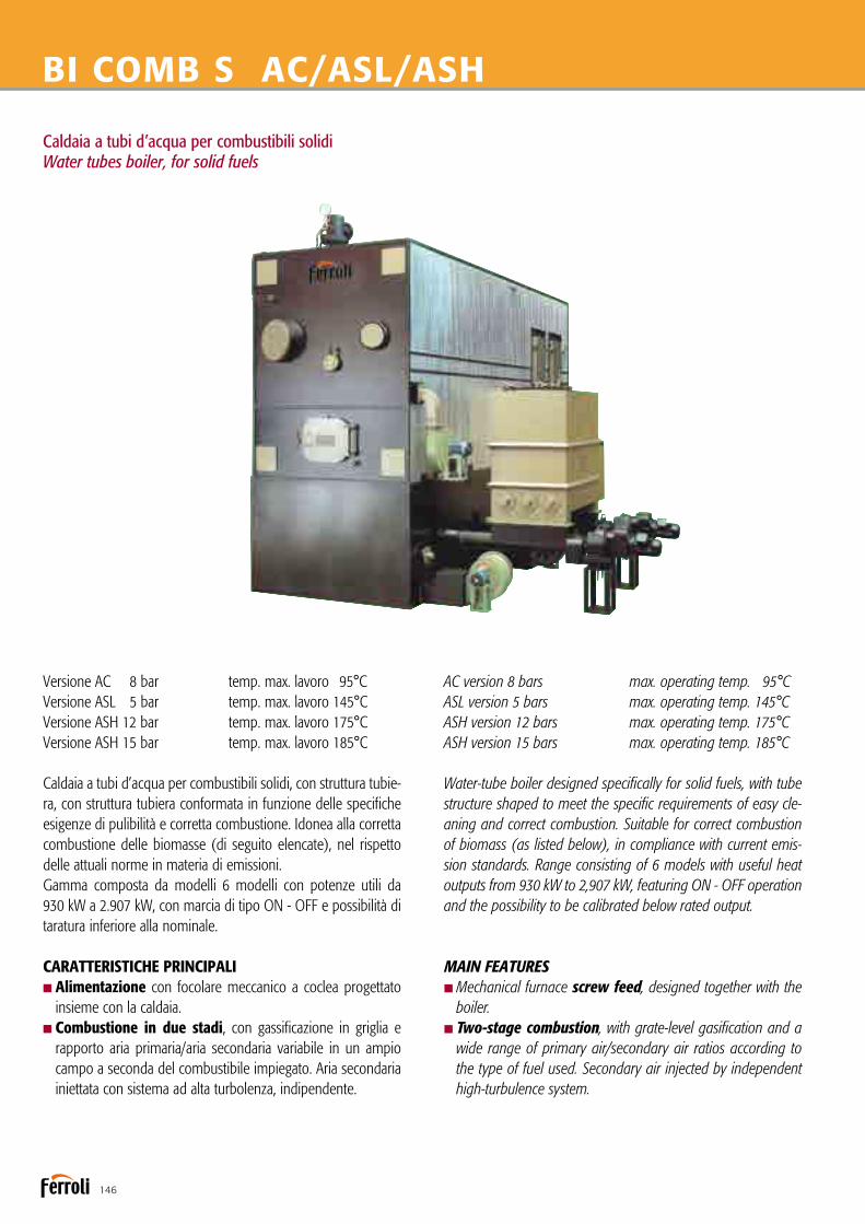
146
Caldaia a tubi d’acqua per combustibili solidiWater tubes boiler, for solid fuels
BI COMB S AC/ASL/ASH
Versione AC 8 bar temp. max. lavoro 95°CVersione ASL 5 bar temp. max. lavoro 145°CVersione ASH 12 bar temp. max. lavoro 175°CVersione ASH 15 bar temp. max. lavoro 185°C
Caldaia a tubi d’acqua per combustibili solidi, con struttura tubie-ra, con struttura tubiera conformata in funzione delle specifiche esigenze di pulibilità e corretta combustione. Idonea alla corretta combustione delle biomasse (di seguito elencate), nel rispetto delle attuali norme in materia di emissioni.Gamma composta da modelli 6 modelli con potenze utili da 930 kW a 2.907 kW, con marcia di tipo ON - OFF e possibilità di taratura inferiore alla nominale.
CARATTERISTICHE PRINCIPALInAlimentazione con focolare meccanico a coclea progettato insieme con la caldaia.nCombustione in due stadi, con gassificazione in griglia e
rapporto aria primaria/aria secondaria variabile in un ampio campo a seconda del combustibile impiegato. Aria secondaria iniettata con sistema ad alta turbolenza, indipendente.
AC version 8 bars max. operating temp. 95°CASL version 5 bars max. operating temp. 145°CASH version 12 bars max. operating temp. 175°CASH version 15 bars max. operating temp. 185°C
Water-tube boiler designed specifically for solid fuels, with tube structure shaped to meet the specific requirements of easy cle-aning and correct combustion. Suitable for correct combustion of biomass (as listed below), in compliance with current emis-sion standards. Range consisting of 6 models with useful heat outputs from 930 kW to 2,907 kW, featuring ON - OFF operation and the possibility to be calibrated below rated output.
MAIN FEATURESnMechanical furnace screw feed, designed together with the boiler.nTwo-stage combustion, with grate-level gasification and a
wide range of primary air/secondary air ratios according to the type of fuel used. Secondary air injected by independent high-turbulence system.

147
nVery wide and high combustion chamber, partially cooled,for the correct duration of the hot flue gas at temperatures varying between 1,100 and 1,300°C, depending on the fuel used.
nUpper post-combustion chamber, with high turbulence, thanks to the special secondary air injection system.nHigh-quality mixed cast and brick refractory cladding
according to the zone (AL2O3>62%), with the possibility of specific refractory cladding for special fuels.
nTube bundle and shape of flue gas path guarantees mini-mum cleaning operations and complete accessibility and complete access, with efficiency exceeding 90%.
nReduced specific heat loads at the furnace.nCompletely tubular structure.nLower water content, therefore less thermal inertia and greater rapidity in reaching steady operating conditions.nLess dangerous in the event of leaks or explosions.
CERTIFICATIONCE Mark in accordance with following Directives: Machinery (2006/42 EEC)Low Voltage (2014/35/UE)Electromagnetic Compatibility (2014/30/UE)Pressure Equipment (2014/68/UE) not for AC version.
nCamera di combustione parzialmente raffreddata molto ampia e alta, per un corretto tempo di permanenza dei fumi caldi a temperature variabili tra i 1.100 e i 1.300°C a seconda del combustibile.
nCamera di postcombustione superiore ad alta turbolenza grazie al particolare sistema di iniezione dell’aria secondaria.nIl rivestimento refrattario, del tipo misto in gettata e in mattoni
a seconda delle diverse zone, è di elevato standard (AL2O3 > 62%) con possibilità di refrattari specifici per combustibili particolari.
nFascio tubiero e geometria del percorso fumi tali da garanti-re un numero minimo di interventi di pulizia ed accessibilità totale superare rendimenti del 90%.
nRidotti carichi termici specifici al focolare.nStruttura interamente tubolare.nMinore contenuto d’acqua, pertanto minore volano termico e maggiore rapidità nel raggiungere le condizioni di regime.nMinore pericolosità in caso di perdite o scoppi.
CERTIFICAZIONIMarcature CE secondo le Direttive: Macchine (2006/42 CEE)Bassa Tensione (2014/35/UE) Compatibilità Elettromagnetica (2014/30/UE)Apparecchi a pressione (2014/68/UE) no per versione AC.
1.1 CAMERA DI COMBUSTIONE 1.2 CAMERA DI POSTCOMBUSTIONE 1.3 PORTA CAMERA COMBUSTIONE 1.4 PORTA PULIZIA SOPRAVOLTINO 1.5 PORTINA ANTISCOPPIO 1.6 FASCIO TUBIERO 1.7 SETTI DEFLETTORI FUMI 1.8 VENTILATORE ARIA SECONDARIA 1.9 FLANGIA ISPEZIONE COLLETTORI 1.10 USCITA FUMI 2.1 PORTA DI PULIZIA 2.2 VENTILATORE ARIA PRIMARIA 3.1 MOTOVARIATORE 3.2 ALIMENTATORE A COCLEA 3.3 GRIGLIA DI COMBUSTIONE 3.4 TRAMOGGIA CON SISTEMA CONTROLLO DI LIVELLO 3.5 RASCHIATORE MOTORIZZATO
1.1 COMBUSTION CHAMBER 1.2 POST-COMBUSTION CHAMBER 1.3 COMBUSTION CHAMBER DOOR 1.4 CLEANING DOOR ABOVE THE ARCH 1.5 EXPLOSION-PROOF DOOR 1.6 TUBE BUNDLE 1.7 FLUE GAS DEFLECTOR BAFFLES 1.8 SECONDARY AIR FAN 1.9 MANIFOLD INSPECTION FLANGE 1.10 FLUE GAS OUTLET 2.1 CLEANING DOOR 2.2 PRIMARY AIR FAN 3.1 VARIABLE SPEED MOTOR 3.2 FEED SCREW 3.3 COMBUSTION GRATE 3.4 HOPPER WITH LEVEL CONTROL SYSTEM 3.5 MOTOR-DRIVEN SCRAPER

148
BI COMB S AC/ASL/ASHDIMENSIONIDIMENSIONS
DATI TECNICITECHNICAL DATA
BI COMB S 800 1000 1200 1600 2000 2500
Potenzialità generatore / Generator heat input kW 930 1163 1396 1861 2326 2907
Portata termica / Heat input kW 1094 1368 1642 2189 2736 3420
Contenuto d’acqua / Water content dm3 1120 1280 1560 1870 2260 2600
Volume camera combustione / Combustion chamber volume m3 4,9 4,9 6,8 6,8 9,5 10,6
Volume camera post-combustione / Post-combustion chamber volume m3 3,8 3,8 4,5 4,5 5,9 6,2
Superficie reale di scambio / Actual exchange surface m2 60 74 78 116 145 170
Superficie griglia mobile / Mobile grate surface m2 1,26 1,26 1,49 1,49 1,72 1,72 Lato fumi / Smoke side ∆p mbar 4,6 5,6 4,6 5,6 6,6 8,7
Lato acqua / Water side ∆p mbar 160 180 210 250 350 390
BI COMB S 800 1000 1200 1600 2000 2500
DIMENSIONI A mm 2300 2300 2500 2500 2870 2870 DIMENSIONS B mm 1970 1970 2090 2090 2290 2290 C mm 4538 4938 5209 5809 6100 6748 E mm 1120 1120 1140 1140 1150 1150 F mm 2099 2099 2194 2194 2245 2315 G mm 2010 2010 2080 2080 2120 2120 H mm 3610 3610 3880 3880 4320 4390 L mm 608 608 568 568 548 556 a1-a2 DN 100 100 125 125 150 150 a3 lungh. boccaglio / draught tube length mm 170-240 170-240 170-240 170-240 170-240 170-240 a3 Ø boccaglio max / max draught tube dia. mm 150 150 150 150 150 150 a4 mm 600x300 600x300 700x350 700x350 800x400 800x400 a5 mm 260x160 260x160 260x160 260x160 260x160 260x160 a6 mm 220x160 220x160 220x160 220x160 220x160 220x160 Peso caldaia / Boiler weight kg 11500 13200 17300 20900 23500 28000 Peso basamento / Boiler bed weight kg 5100 5600 6500 7500 9600 11000 Peso tramoggia / Hopper weight kg 340 340 340 340 340 340 Peso focolare meccanico
kg 380 380 530 530 750 750 Mechanical furnace weight
Legenda1 Corpo caldaia2 Basamento3 Tramoggia4 Focolare meccanico
a1 Mandataa2 Ritornoa3 Attacco bruciatore pilotaa4 Attacco caminoa5 Caricamento tramoggiaa6 Estrazione ceneri
Key1 Boiler body2 Boiler bed3 Hopper4 Mechanical furnace
a1 Outleta2 Returna3 Pilot burner connectiona4 Flue connectiona5 Hopper loadinga6 Ash removal

149
ACCESSORI A RICHIESTA
nPotenza termica modulata in continuo: permette di ridur-re la potenzialità bruciata dal 100 fino al 50%, riducendo al minimo gli spegnimenti della caldaia. La sonda di mandata agisce sul regolatore a logica programmabile che modifica la velocità della coclea di alimentazione e le portate d’aria com-burente mediante inverter.
nRegolatore di tiraggio: mantiene costante, il tiraggio in camera di combustione tramite un rilevatore ed una valvola a farfalla motorizzata sul condotto di by-pass della batteria multiciclonica oppure inverter sull’aspiratore fumi.
nBruciatore di accensione o pilota: per la prima accensionedel combustibile (indispensabile per materiali con elevata umidità), ad una sola fiamma può essere alimentato da gasolio o gas metano. Inserimento ed arretramento in caldaia può essere automatizzato mediante sistema pneumatico.
nAnalizzatore con controllo in continuo: lettura su displaydi: CO - O2, temperatura fumi camino (obbligatori secondo DM 05/02/98 per potenze superiori a 1 MW).
nSistema di registrazione dati sulle emisssioni fumi al camino “Trend View”: software di acquisizione dati in conti-nuo. I dati raccolti possono essere ordinati in formato tabellare secondo quanto richiesto dal D.Lgs. 152/06.
nSistema pulizia ad onda d’urto SBS: il sistema è composto da una serie di soffiatori ad onda d’urto applicati sulla struttura caldaia, e da un temporizzatore. Le polveri residue vengono trasportate dal flusso dei fumi e vengono decantate del siste-ma di filtrazione a valle della caldaia. Il sistema funziona con caldaia in marcia.
nRicircolo fumi in camera di combustione per abbatti-mento NOx: il sistema permette di completare la combustio-ne con una temperatura costante e più bassa rispetto ad una combustione senza il ricircolo.
ACCESSORIES AVAILABLE ON REQUEST
nContinuous heat output modulation: allows the heatinput to be reduced continuously from 100% to 50% minimi-sing the number of boiler shut-downs. A programmable logic controller connected to the water outlet temperature probe varies the rotation speeds respectively of the fuel feed screw and the combustion air fans using inverters.
nDraught regulator: this keeps the draught in the combu-stion chamber constant, using a sensor device and a motor-driven throttle valve on the centrifugal dust separator assem-bly bypass duct or the flue gas exhaust inverter.
nIgnition or pilot burner: allows automatic initial ignition ofthe fuel (essential for materials with a high moisture content), single flame, operating on oil or natural gas. A pneumatic system automatically controls its entry into and return out of the boiler.
nAnalyser with continuous control: reading on display of CO - O2, flue gas temperature (required by legislation for heat outputs exceeding 1 MW).
n“Trend View” system for recording data on flue gasemissions: software for continuous data acquisition. The data can be processed the data in table form (as required by certain legislation).
nSBS shockwave cleaning system: the system is made up of a series of shockwave blowers fitted on the boiler structure, and a timer. The residual dust from combustion removed from the tube bundle is carried by the flue gas and decants in the filtration system downstream of the boiler. The system works with the boiler operating.
nFlue gas recirculation in the combustion chamber forNOx reduction: the system allows combustion to occur at a constant and lower temperature than combustion without recirculation.
COMBUSTIBILI COMPATIBILI TIPOLOGIA
nRifiuti della prima e seconda lavorazione del legno e del sughero non trattati.
nBiomasse (Scarti vegetali di attività agricole, forestali, di prima lavorazione dei prodotti agroalimentari, sanse esauste, vinac-cioli, farina di vinaccioli, residui di frutta, buccette e altri residui vegetali).
nPellets di legno.
GRANULOMETRIA MASSIMA AMMESSA, UMIDITÀ DEL COMBUSTIBILE, GARANZIE SUL PROCESSO DI COMBUSTIONE E SULLE EMISSIONI AL CAMINO, saranno definite su specifiche richieste a livello contrattuale.
COMPATIBLE FUEL TYPES
nWaste from the first and second processing of untreated wood and cork.nBiomass (plant waste from agricultural and forestry activities
and from the first processing of agricultural and food pro-ducts, depleted pomace, grape seed, grape seed flour, fruit residues, peels and other plant residues).
nWood pellets.
MAXIMUM GRAIN SIZE ALLOWED, FUEL MOISTURE CONTENT, GUARANTEES ON THE COMBUSTION PROCESS AND EMISSIONS, will be defined contractually, based on specific requirements.

150
Caldaia a tubi d’acqua per combustibili solidiWater tubes boiler, for solid fuels
BI COMB S LP/HP
Versione LP 1 bar Versione HP 12 bar Versione HP 15 bar
Caldaia a tubi d’acqua per combustibili solidi, con struttura tubie-ra, con struttura tubiera conformata in funzione delle specifiche esigenze di pulibilità e corretta combustione. Idonea alla corretta combustione delle biomasse (di seguito elencate), nel rispetto delle attuali norme in materia di emissioni.Gamma composta da modelli 6 modelli con potenze utili da 930 kW a 2.907 kW, con marcia di tipo ON - OFF e possibilità di taratura inferiore alla nominale.
CARATTERISTICHE PRINCIPALInAlimentazione con focolare meccanico a coclea progettato insieme con la caldaia.nCombustione in due stadi, con gassificazione in griglia e
rapporto aria primaria/aria secondaria variabile in un ampio campo a seconda del combustibile impiegato. Aria secondaria iniettata con sistema ad alta turbolenza, indipendente.
LP version 1 bars HP version 12 bars HP version 15 bars
Water-tube boiler designed specifically for solid fuels, with tube structure shaped to meet the specific requirements of easy cle-aning and correct combustion. Suitable for correct combustion of biomass (as listed below), in compliance with current emis-sion standards. Range consisting of 6 models with useful heat outputs from 930 kW to 2,907 kW, featuring ON - OFF operation and the possibility to be calibrated below rated output.
MAIN FEATURESnMechanical furnace screw feed, designed together with the boiler.nTwo-stage combustion, with grate-level gasification and a
wide range of primary air/secondary air ratios according to the type of fuel used. Secondary air injected by independent high-turbulence system.

151
nVery wide and high combustion chamber, partially cooled,for the correct duration of the hot flue gas at temperatures varying between 1,100 and 1,300°C, depending on the fuel used.
nUpper post-combustion chamber, with high turbulence, thanks to the special secondary air injection system.nHigh-quality mixed cast and brick refractory cladding
according to the zone (AL2O3>62%), with the possibility of specific refractory cladding for special fuels.
nTube bundle and shape of flue gas path guarantees mini-mum cleaning operations and complete accessibility and complete access, with efficiency exceeding 90%.
nReduced specific heat loads at the furnace.nCompletely tubular structure.nLower water content, therefore less thermal inertia and greater rapidity in reaching steady operating conditions.nLess dangerous in the event of leaks or explosions.
CERTIFICATIONCE Mark in accordance with following Directives: Machinery (2006/42 EEC)Low Voltage (2014/35/UE)Electromagnetic Compatibility (2014/30/UE)Pressure Equipment (2014/68/UE)
nCamera di combustione parzialmente raffreddata molto ampia e alta, per un corretto tempo di permanenza dei fumi caldi a temperature variabili tra i 1.100 e i 1.300°C a seconda del combustibile.
nCamera di postcombustione superiore ad alta turbolenza grazie al particolare sistema di iniezione dell’aria secondaria.nIl rivestimento refrattario, del tipo misto in gettata e in mat-
toni a seconda delle diverse zone, è di elevato standard (AL2O3 > 62%) con possibilità di refrattari specifici per combustibili particolari.
nFascio tubiero e geometria del percorso fumi tali da garanti-re un numero minimo di interventi di pulizia ed accessibilità totale superare rendimenti del 90%.
nRidotti carichi termici specifici al focolare.nStruttura interamente tubolare.nMinore contenuto d’acqua, pertanto minore volano termico e maggiore rapidità nel raggiungere le condizioni di regime.nMinore pericolosità in caso di perdite o scoppi.
CERTIFICAZIONIMarcature CE secondo le Direttive: Macchine (2006/42 CEE)Bassa Tensione (2014/35/UE) Compatibilità Elettromagnetica (2014/30/UE)Apparecchi a pressione (2014/68/UE)
1.1 CAMERA DI COMBUSTIONE 1.2 CAMERA DI POSTCOMBUSTIONE 1.3 PORTA CAMERA COMBUSTIONE 1.4 PORTA PULIZIA SOPRAVOLTINO 1.5 PORTINA ANTISCOPPIO 1.6 FASCIO TUBIERO 1.7 SETTI DEFLETTORI FUMI 1.8 VENTILATORE ARIA SECONDARIA 1.9 FLANGIA ISPEZIONE COLLETTORI 1.10 USCITA FUMI 2.1 PORTA DI PULIZIA 2.2 VENTILATORE ARIA PRIMARIA 3.1 MOTOVARIATORE 3.2 ALIMENTATORE A COCLEA 3.3 GRIGLIA DI COMBUSTIONE 3.4 TRAMOGGIA CON SISTEMA CONTROLLO DI LIVELLO 3.5 RASCHIATORE MOTORIZZATO
1.1 COMBUSTION CHAMBER 1.2 POST-COMBUSTION CHAMBER 1.3 COMBUSTION CHAMBER DOOR 1.4 CLEANING DOOR ABOVE THE ARCH 1.5 EXPLOSION-PROOF DOOR 1.6 TUBE BUNDLE 1.7 FLUE GAS DEFLECTOR BAFFLES 1.8 SECONDARY AIR FAN 1.9 MANIFOLD INSPECTION FLANGE 1.10 FLUE GAS OUTLET 2.1 CLEANING DOOR 2.2 PRIMARY AIR FAN 3.1 VARIABLE SPEED MOTOR 3.2 FEED SCREW 3.3 COMBUSTION GRATE 3.4 HOPPER WITH LEVEL CONTROL SYSTEM 3.5 MOTOR-DRIVEN SCRAPER
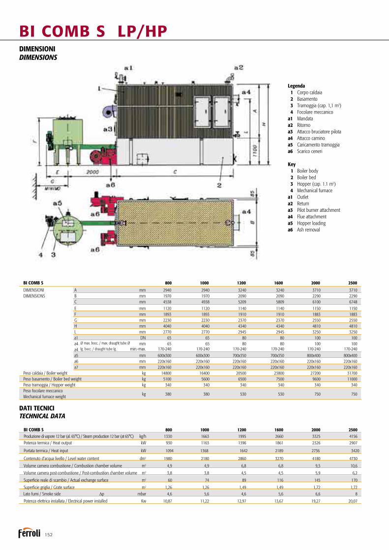
152
BI COMB S 800 1000 1200 1600 2000 2500
DIMENSIONI A mm 2940 2940 3240 3240 3710 3710 DIMENSIONS B mm 1970 1970 2090 2090 2290 2290 C mm 4538 4938 5209 5809 6100 6748 E mm 1120 1120 1140 1140 1150 1150 F mm 1893 1893 1910 1910 1883 1883 G mm 2230 2230 2370 2370 2550 2550 H mm 4040 4040 4340 4340 4810 4810 L mm 2770 2770 2945 2945 3250 3250 a1 DN 65 65 80 80 100 100 a4 Ø max. bocc. / max. draught tube Ø mm 65 65 80 80 100 100 a4 lg. bocc. / draught tube lg. min.-max. 170-240 170-240 170-240 170-240 170-240 170-240 a5 mm 600x300 600x300 700x350 700x350 800x400 800x400 a6 mm 220x160 220x160 220x160 220x160 220x160 220x160 a7 mm 220x160 220x160 220x160 220x160 220x160 220x160 Peso caldaia / Boiler weight kg 14800 16400 20500 23800 27200 31700 Peso basamento / Boiler bed weight kg 5100 5600 6500 7500 9600 11000 Peso tramoggia / Hopper weight kg 340 340 340 340 340 340 Peso focolare meccanico
kg 380 380 530 530 750 750 Mechanical furnace weight
BI COMB S LP/HPDIMENSIONIDIMENSIONS
DATI TECNICITECHNICAL DATA
Legenda 1 Corpo caldaia 2 Basamento 3 Tramoggia (cap. 1,1 m3) 4 Focolare meccanicoa1 Mandataa2 Ritornoa3 Attacco bruciatore pilotaa4 Attacco caminoa5 Caricamento tramoggiaa6 Scarico ceneri
Key 1 Boiler body 2 Boiler bed 3 Hopper (cap. 1.1 m3) 4 Mechanical furnacea1 Outleta2 Returna3 Pilot burner attachmenta4 Flue attachmenta5 Hopper loadinga6 Ash removal
BI COMB S 800 1000 1200 1600 2000 2500
Produzione di vapore 12 bar (al. 65°C) / Steam production 12 bar (at 65°C) kg/h 1330 1663 1995 2660 3325 4156
Potenza termica / Heat output kW 930 1163 1396 1861 2326 2907
Portata termica / Heat input kW 1094 1368 1642 2189 2736 3420
Contenuto d’acqua livello / Level water content dm3 1980 2180 2860 3270 4180 4730
Volume camera combustione / Combustion chamber volume m3 4,9 4,9 6,8 6,8 9,5 10,6
Volume camera post-combustione / Post-combustion chamber volume m3 3,8 3,8 4,5 4,5 5,9 6,2
Superficie reale di scambio / Actual exchange surface m2 60 74 89 116 145 170
Superficie griglia / Grate surface m2 1,26 1,26 1,49 1,49 1,72 1,72 Lato fumi / Smoke side ∆p mbar 4,6 5,6 4,6 5,6 6,6 8
Potenza elettrica installata / Electrical power installed Kw 10,87 11,22 12,97 13,67 19,27 20,07

153
ACCESSORI A RICHIESTA
nPotenza termica modulata in continuo: permette di ridur-re la potenzialità bruciata dal 100 fino al 50%, riducendo al minimo gli spegnimenti della caldaia. La sonda di mandata agisce sul regolatore a logica programmabile che modifica la velocità della coclea di alimentazione e le portate d’aria com-burente mediante inverter.
nRegolatore di tiraggio: mantiene costante, il tiraggio in camera di combustione tramite un rilevatore ed una valvola a farfalla motorizzata sul condotto di by-pass della batteria multiciclonica oppure inverter sull’aspiratore fumi.
nBruciatore di accensione o pilota: per la prima accensionedel combustibile (indispensabile per materiali con elevata umidità), ad una sola fiamma può essere alimentato da gasolio o gas metano. Inserimento ed arretramento in caldaia può essere automatizzato mediante sistema pneumatico.
nAnalizzatore con controllo in continuo: lettura su displaydi: CO - O2, temperatura fumi camino (obbligatori secondo DM 05/02/98 per potenze superiori a 1 MW).
nSistema di registrazione dati sulle emisssioni fumi al camino “Trend View”: software di acquisizione dati in conti-nuo. I dati raccolti possono essere ordinati in formato tabellare secondo quanto richiesto dal D.Lgs. 152/06.
nSistema pulizia ad onda d’urto SBS: il sistema è composto da una serie di soffiatori ad onda d’urto applicati sulla struttura caldaia, e da un temporizzatore. Le polveri residue vengono trasportate dal flusso dei fumi e vengono decantate del siste-ma di filtrazione a valle della caldaia. Il sistema funziona con caldaia in marcia.
nRicircolo fumi in camera di combustione per abbatti-mento NOx: il sistema permette di completare la combustio-ne con una temperatura costante e più bassa rispetto ad una combustione senza il ricircolo.
ACCESSORIES AVAILABLE ON REQUEST
nContinuous heat output modulation: allows the heatinput to be reduced continuously from 100% to 50% minimi-sing the number of boiler shut-downs. A programmable logic controller connected to the water outlet temperature probe varies the rotation speeds respectively of the fuel feed screw and the combustion air fans using inverters.
nDraught regulator: this keeps the draught in the combu-stion chamber constant, using a sensor device and a motor-driven throttle valve on the centrifugal dust separator assem-bly bypass duct or the flue gas exhaust inverter.
nIgnition or pilot burner: allows automatic initial ignition ofthe fuel (essential for materials with a high moisture content), single flame, operating on oil or natural gas. A pneumatic system automatically controls its entry into and return out of the boiler.
nAnalyser with continuous control: reading on display of CO - O2, flue gas temperature (required by legislation for heat outputs exceeding 1 MW).
n“Trend View” system for recording data on flue gasemissions: software for continuous data acquisition. The data can be processed the data in table form (as required by certain legislation).
nSBS shockwave cleaning system: the system is made up of a series of shockwave blowers fitted on the boiler structure, and a timer. The residual dust from combustion removed from the tube bundle is carried by the flue gas and decants in the filtration system downstream of the boiler. The system works with the boiler operating.
nFlue gas recirculation in the combustion chamber forNOx reduction: the system allows combustion to occur at a constant and lower temperature than combustion without recirculation.
COMBUSTIBILI COMPATIBILI TIPOLOGIA
nRifiuti della prima e seconda lavorazione del legno e del sughero non trattati.
nBiomasse (Scarti vegetali di attività agricole, forestali, di prima lavorazione dei prodotti agroalimentari, sanse esauste, vinac-cioli, farina di vinaccioli, residui di frutta, buccette e altri residui vegetali).
nPellets di legno.
GRANULOMETRIA MASSIMA AMMESSA, UMIDITÀ DEL COMBUSTIBILE, GARANZIE SUL PROCESSO DI COMBUSTIONE E SULLE EMISSIONI AL CAMINO, saranno definite su specifiche richieste a livello contrattuale.
COMPATIBLE FUEL TYPES
nWaste from the first and second processing of untreated wood and cork.nBiomass (plant waste from agricultural and forestry activities
and from the first processing of agricultural and food pro-ducts, depleted pomace, grape seed, grape seed flour, fruit residues, peels and other plant residues).
nWood pellets.
MAXIMUM GRAIN SIZE ALLOWED, FUEL MOISTURE CONTENT, GUARANTEES ON THE COMBUSTION PROCESS AND EMISSIONS, will be defined contractually, based on specific requirements.

154
Caldaia a tubi d’acqua per combustibili solidi, a griglia mobileWater tubes boiler, for solid fuels, with mobile grate
BI COMB SGM AC/ASL/ASH
Versione AC 8 bar temp. max. lavoro 95°CVersione ASL 5 bar temp. max. lavoro 145°CVersione ASH 12 bar temp. max. lavoro 175°CVersione ASH 15 bar temp. max. lavoro 185°C
Caldaia a tubi d’acqua concepita appositamente per combustibili solidi, con struttura tubiera conformata in funzione delle speci-fiche esigenze di pulibilità e corretta combustione. Idonea alla corretta combustione delle biomasse (di seguito elencate), nel rispetto delle attuali norme in materia di emissioni.Gamma composta da modelli 9 modelli con potenze utili da 930 kW a 5.815 kW, con marcia di tipo ON - OFF e possibilità di taratura inferiore alla nominale.
CARATTERISTICHE PRINCIPALInAlimentazione con focolare meccanico a coclea progettato insieme con la caldaia.nCombustione in due stadi, con gassificazione in griglia e
rapporto aria primaria/aria secondaria variabile in un ampio campo a seconda del combustibile impiegato. Aria secondaria iniettata con sistema ad alta turbolenza, indipendente.
AC version 8 bars max. operating temp. 95°CASL version 5 bars max. operating temp. 145°CASH version 12 bars max. operating temp. 175°CASH version 15 bars max. operating temp. 185°C
Water-tube boiler designed specifically for solid fuels, with tube structure shaped to meet the specific requirements of easy cleaning and correct combustion. Suitable for correct combustion of biomass (as listed below), in compliance with current emission standards. Range consisting of 9 models with useful heat outputs from 930 kW to 5,815 kW, featuring ON - OFF operation and the possibi-lity to be calibrated below rated output.
MAIN FEATURESnMechanical furnace screw feed, designed together with the boiler.nTwo-stage combustion, with grate-level gasification and a
wide range of primary air/secondary air ratios according to the type of fuel used. Secondary air injected by independent high-turbulence system.
nVery wide and high combustion chamber, partially cooled,

155
for the correct duration of the hot flue gas at temperatures varying between 1,100 and 1,300°C, depending on the fuel used.
nUpper post-combustion chamber, with high turbulence, thanks to the special secondary air injection system.nHigh-quality mixed cast and brick refractory cladding
according to the zone (AL2O3>62%), with the possibility of specific refractory cladding for special fuels.
nTube bundle and shape of flue gas path guarantees mini-mum cleaning operations and complete accessibility and complete access, with efficiency exceeding 90%.
nReduced specific heat loads at the furnace.nCompletely tubular structure.nLower water content, therefore less thermal inertia and greater rapidity in reaching steady operating conditions.nLess dangerous in the event of leaks or explosions.
CERTIFICATIONCE Mark in accordance with following Directives:Machinery (2006/42 EEC)Low Voltage (2014/35/UE)Electromagnetic Compatibility (2014/30/UE)Pressure Equipment (2014/68/UE) not for AC version.
nCamera di combustione parzialmente raffreddata moltoampia e alta, per un corretto tempo di permanenza dei fumi caldi a temperature variabili tra i 1.100 e i 1.300°C a seconda del combustibile.
nCamera di postcombustione superiore ad alta turbolenza grazie al particolare sistema di iniezione dell’aria secondaria. nIl rivestimento refrattario, del tipo misto in gettata e in mat-
toni a seconda delle diverse zone, è di elevato standard (AL2O3 > 62%) con possibilità di refrattari specifici per combustibili particolari.
nFascio tubiero e geometria del percorso fumi tali da garanti-re un numero minimo di interventi di pulizia ed accessibilità totale superare rendimenti del 90%.
nRidotti carichi termici specifici al focolare.nStruttura interamente tubolare.nMinore contenuto d’acqua, pertanto minore volano termico e maggiore rapidità nel raggiungere le condizioni di regime.nMinore pericolosità in caso di perdite o scoppi.
CERTIFICAZIONIMarcature CE secondo le Direttive: Macchine (2006/42 CEE)Bassa Tensione (2014/35/UE) Compatibilità Elettromagnetica (2014/30/UE)Apparecchi a pressione (2014/68/UE) no per versione AC.
1.1 CAMERA DI COMBUSTIONE 1.2 CAMERA DI POSTCOMBUSTIONE 1.3 PORTA CAMERA COMBUSTIONE 1.4 PORTA PULIZIA SOPRAVOLTINO 1.6 FASCIO TUBIERO 1.7 SETTI DEFLETTORI FUMI 1.9 FLANGIA ISPEZIONE COLLETTORI 1.10 USCITA FUMI 2.1 PORTA DI PULIZIA 2.2 SISTEMA DI ALIMENTAZIONE A COCLEA
1.1 COMBUSTION CHAMBER 1.2 POST-COMBUSTION CHAMBER 1.3 COMBUSTION CHAMBER DOOR 1.4 CLEANING DOOR ABOVE THE ARCH 1.6 TUBE BUNDLE 1.7 FLUE GAS DEFLECTOR BAFFLES 1.9 MANIFOLD INSPECTION FLANGE 1.10 FLUE GAS OUTLET 2.1 CLEANING DOOR 2.2 SCREW FEED SYSTEM
1.1 1.2 1.6 1.7 1.9
1.101.4
1.3
2.2 2.1
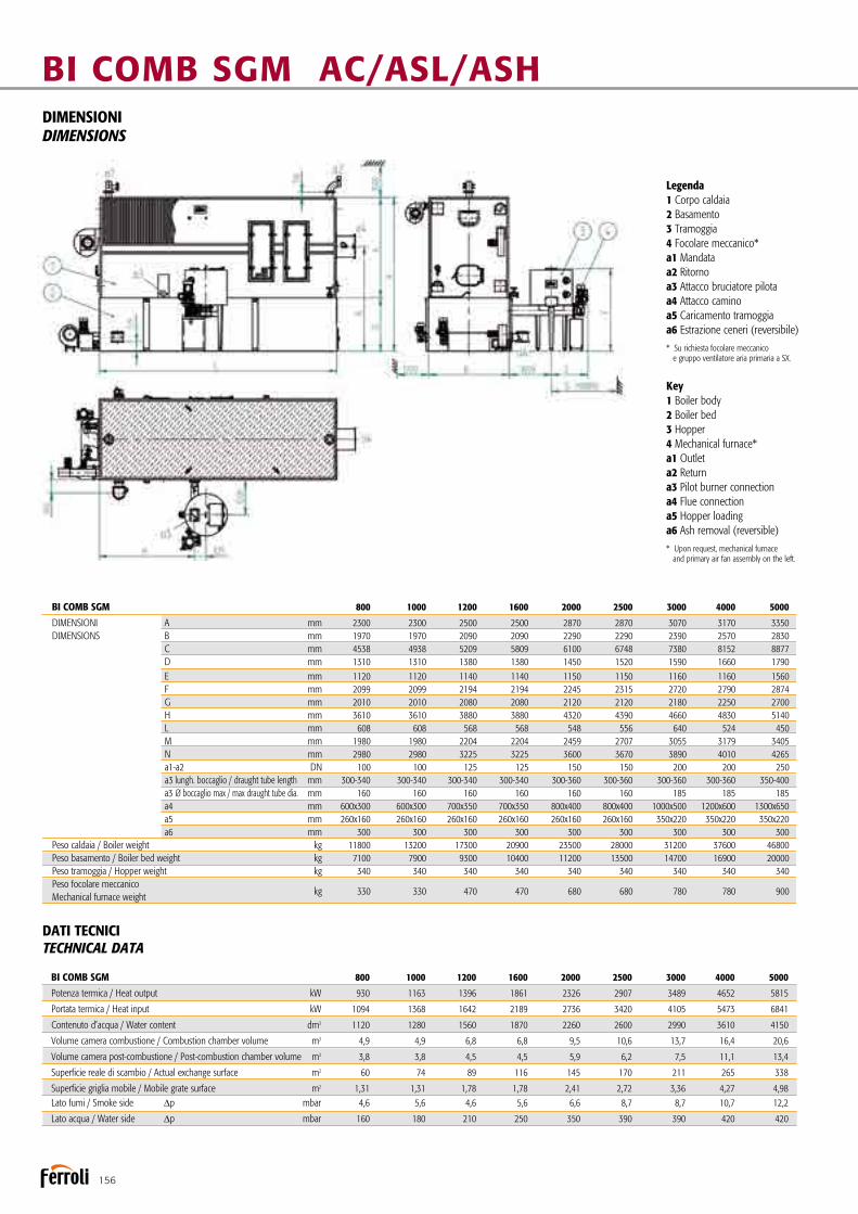
156
BI COMB SGM AC/ASL/ASHDIMENSIONIDIMENSIONS
DATI TECNICITECHNICAL DATA
BI COMB SGM 800 1000 1200 1600 2000 2500 3000 4000 5000
Potenza termica / Heat output kW 930 1163 1396 1861 2326 2907 3489 4652 5815
Portata termica / Heat input kW 1094 1368 1642 2189 2736 3420 4105 5473 6841
Contenuto d’acqua / Water content dm3 1120 1280 1560 1870 2260 2600 2990 3610 4150
Volume camera combustione / Combustion chamber volume m3 4,9 4,9 6,8 6,8 9,5 10,6 13,7 16,4 20,6
Volume camera post-combustione / Post-combustion chamber volume m3 3,8 3,8 4,5 4,5 5,9 6,2 7,5 11,1 13,4
Superficie reale di scambio / Actual exchange surface m2 60 74 89 116 145 170 211 265 338
Superficie griglia mobile / Mobile grate surface m2 1,31 1,31 1,78 1,78 2,41 2,72 3,36 4,27 4,98 Lato fumi / Smoke side ∆p mbar 4,6 5,6 4,6 5,6 6,6 8,7 8,7 10,7 12,2
Lato acqua / Water side ∆p mbar 160 180 210 250 350 390 390 420 420
BI COMB SGM 800 1000 1200 1600 2000 2500 3000 4000 5000
DIMENSIONI A mm 2300 2300 2500 2500 2870 2870 3070 3170 3350 DIMENSIONS B mm 1970 1970 2090 2090 2290 2290 2390 2570 2830 C mm 4538 4938 5209 5809 6100 6748 7380 8152 8877 D mm 1310 1310 1380 1380 1450 1520 1590 1660 1790 E mm 1120 1120 1140 1140 1150 1150 1160 1160 1560 F mm 2099 2099 2194 2194 2245 2315 2720 2790 2874 G mm 2010 2010 2080 2080 2120 2120 2180 2250 2700 H mm 3610 3610 3880 3880 4320 4390 4660 4830 5140 L mm 608 608 568 568 548 556 640 524 450 M mm 1980 1980 2204 2204 2459 2707 3055 3179 3405 N mm 2980 2980 3225 3225 3600 3670 3890 4010 4265 a1-a2 DN 100 100 125 125 150 150 200 200 250 a3 lungh. boccaglio / draught tube length mm 300-340 300-340 300-340 300-340 300-360 300-360 300-360 300-360 350-400 a3 Ø boccaglio max / max draught tube dia. mm 160 160 160 160 160 160 185 185 185 a4 mm 600x300 600x300 700x350 700x350 800x400 800x400 1000x500 1200x600 1300x650 a5 mm 260x160 260x160 260x160 260x160 260x160 260x160 350x220 350x220 350x220 a6 mm 300 300 300 300 300 300 300 300 300 Peso caldaia / Boiler weight kg 11800 13200 17300 20900 23500 28000 31200 37600 46800 Peso basamento / Boiler bed weight kg 7100 7900 9300 10400 11200 13500 14700 16900 20000 Peso tramoggia / Hopper weight kg 340 340 340 340 340 340 340 340 340 Peso focolare meccanico
kg 330 330 470 470 680 680 780 780 900 Mechanical furnace weight
Legenda1 Corpo caldaia2 Basamento3 Tramoggia4 Focolare meccanico*a1 Mandataa2 Ritornoa3 Attacco bruciatore pilotaa4 Attacco caminoa5 Caricamento tramoggiaa6 Estrazione ceneri (reversibile)
* Su richiesta focolare meccanico e gruppo ventilatore aria primaria a SX.
Key1 Boiler body2 Boiler bed3 Hopper4 Mechanical furnace*a1 Outleta2 Returna3 Pilot burner connectiona4 Flue connectiona5 Hopper loadinga6 Ash removal (reversible)
* Upon request, mechanical furnace and primary air fan assembly on the left.

157
ACCESSORI A RICHIESTA
n Basamento autopulente: permette di pulire in automatico gran parte delle ceneri prodotte durante la combustione e di agevolare le operazioni di pulizia caldaia. Le ceneri vengono destinate in due unici punti dove possono essere stoccate in appositi contenitori (da ordi-nare a parte). Questo optional, abbinato al sistema di pulizia ad onda d’urto, permette di diminuire drasticamente i tempi di fermo macchina.
nPotenza termica modulata in continuo: permette di ridur-re la potenzialità bruciata dal 100 fino al 50%, riducendo al minimo gli spegnimenti della caldaia. La sonda di mandata agisce sul regolatore a logica programmabile che modifica la velocità della coclea di alimen-tazione e le portate d’aria comburente mediante inverter.
nRegolatore di tiraggio: mantiene costante, il tiraggio incamera di combustione tramite un rilevatore ed una valvola a farfalla motorizzata sul condotto di by-pass della batteria multiciclonica oppu-re inverter sull’aspiratore fumi.
nBruciatore di accensione o pilota: per la prima accensionedel combustibile (indispensabile per materiali con elevata umidità), ad una sola fiamma può essere alimentato da gasolio o gas metano. Inserimento ed arretramento in caldaia può essere automatizzato mediante sistema pneumatico.
nAnalizzatore con controllo in continuo: lettura su display di: CO - O2, temperatura fumi camino (obbligatori secondo DM 05/02/98 per potenze superiori a 1 MW).
n Sistema di registrazione dati sulle emissioni fumi al camino “Trend View”: software di acquisizione dati in continuo. I dati raccolti possono essere ordinati in formato tabellare secondo quanto richiesto dal D.Lgs. 152/06.
n Sistema pulizia ad onda d’urto SBS: il sistema è composto da una serie di soffiatori ad onda d’urto applicati sulla struttura caldaia, e da un temporizzatore. Le polveri residue vengono trasportate dal flusso dei fumi e vengono decantate del sistema di filtrazione a valle della caldaia. Il sistema funziona con caldaia in marcia.
nRicircolo fumi in camera di combustione per abbatti-mento NOx: il sistema permette di completare la combustione con una temperatura costante e più bassa rispetto ad una combustione senza il ricircolo.
ACCESSORIES AVAILABLE ON REQUEST
n Self-cleaning boiler bed: ensures automatic cleaning of most of the ash produced during combustion and simplifies boiler cleaning operations. The ash is conveyed to two specific collection points where it can be kept in special containers (ordered separately).
This option, combined with the shockwave cleaning system, drastically reduces unit downtime.
nContinuous heat output modulation: allows the heatinput to be reduced continuously from 100% to 50% minimising the number of boiler shut-downs. A programmable logic controller connected to the water outlet temperature probe varies the rotation speeds respectively of the fuel feed screw and the combustion air fans using inverters.
nDraught regulator: this keeps the draught in the combu-stion chamber constant, using a sensor device and a motor-driven throttle valve on the centrifugal dust separator assembly bypass duct or the flue gas exhaust inverter.
n Ignition or pilot burner: allows automatic initial ignition of the fuel (essential for materials with a high moisture content), single flame, operating on oil or natural gas. A pneumatic system automa-tically controls its entry into and return out of the boiler.
n Analyser with continuous control: reading on display of CO - O2, flue gas temperature (required by legislation for heat outputs excee-ding 1 MW).
n “Trend View” system for recording data on flue gas emissions: software for continuous data acquisition. The data can be processed the data in table form (as required by certain legislation).
n SBS shockwave cleaning system: the system is made up of a series of shockwave blowers fitted on the boiler structure, and a timer. The residual dust from combustion removed from the tube bundle is carried by the flue gas and decants in the filtration system downstre-am of the boiler. The system works with the boiler operating.
nFlue gas recirculation in the combustion chamber for NOx reduction: the system allows combustion to occur at a con-stant and lower temperature than combustion without recirculation.
COMBUSTIBILI COMPATIBILI TIPOLOGIAnRifiuti della prima e seconda lavorazione del legno e del sughero non
trattati.nBiomasse (Scarti vegetali di attività agricole, forestali, di prima lavora-
zione dei prodotti agroalimentari, sanse esauste, vinaccioli, farina di vinaccioli, residui di frutta, buccette e altri residui vegetali).
nPellets di legno.nScarti della lavorazione del legno e affini trattati (pannelli tru-
ciolati o multistrato incollati e nobilitati con resine nel tipo e quantità ammesse dalle norme sul riutilizzo dei residui). Temperatura minima di rammollimento delle ceneri: 800°C.
nMassima percentuale di ceneri sul combustibile secco: 4%.
GRANULOMETRIA MASSIMA AMMESSA, UMIDITÀ DEL COMBUSTIBILE, GARANZIE SUL PROCESSO DI COMBUSTIONE E SULLE EMISSIONI AL CAMINO, saranno definite su specifiche richieste a livello contrattuale.
COMPATIBLE FUEL TYPESnWaste from the first and second processing of untreated wood and cork.n Biomass (plant waste from agricultural and forestry activities and
from the first processing of agricultural and food products, depleted pomace, grape seed, grape seed flour, fruit residues, peels and other plant residues).
nWood pellets.n Treated wood processing scrap and similar material (glued particle-
board or multiply finished with resins of the type and in the quantity admissible according to legislation on waste reuse). Minimum tempe-rature of softened ash: 800°C.
nMaximum percentage of ash in dry fuel: 4%.
MAXIMUM GRAIN SIZE ALLOWED, FUEL MOISTURE CONTENT, GUARANTEES ON THE COMBUSTION PROCESS AND EMISSIONS, will be defined contractually, based on specific requirements.

158
Caldaia a tubi d’acqua per combustibili solidi, a griglia mobileWater tubes boiler, for solid fuels, with mobile grate
BI COMB SGM LP/HP
Versione LP 1 bar Versione HP 12 bar Versione HP 15 bar
Caldaia a tubi d’acqua concepita appositamente per combustibili solidi, con struttura tubiera conformata in funzione delle speci-fiche esigenze di pulibilità e corretta combustione. Idonea alla corretta combustione delle biomasse (di seguito elencate), nel rispetto delle attuali norme in materia di emissioni.Gamma composta da modelli 9 modelli con potenze utili da 930 kW a 5.815 kW, con marcia di tipo ON - OFF e possibilità di taratura inferiore alla nominale.
CARATTERISTICHE PRINCIPALInAlimentazione con focolare meccanico a coclea progettato insieme con la caldaia.nCombustione in due stadi, con gassificazione in griglia e
rapporto aria primaria/aria secondaria variabile in un ampio campo a seconda del combustibile impiegato. Aria secondaria iniettata con sistema ad alta turbolenza, indipendente.
LP version 1 bars HP version 12 bars HP version 15 bars
Water-tube boiler designed specifically for solid fuels, with tube structure shaped to meet the specific requirements of easy cleaning and correct combustion. Suitable for correct combustion of biomass (as listed below), in compliance with current emission standards. Range consisting of 9 models with useful heat outputs from 930 kW to 5,815 kW, featuring ON - OFF operation and the possibi-lity to be calibrated below rated output.
MAIN FEATURESnMechanical furnace screw feed, designed together with the boiler.nTwo-stage combustion, with grate-level gasification and a
wide range of primary air/secondary air ratios according to the type of fuel used. Secondary air injected by independent high-turbulence system.

159
nVery wide and high combustion chamber, partially cooled, for the correct duration of the hot flue gas at temperatures varying between 1,100 and 1,300°C, depending on the fuel used.
nUpper post-combustion chamber, with high turbulence, thanks to the special secondary air injection system.nHigh-quality mixed cast and brick refractory cladding
according to the zone (AL2O3>62%), with the possibility of specific refractory cladding for special fuels.
nTube bundle and shape of flue gas path guarantees mini-mum cleaning operations and complete accessibility and complete access, with efficiency exceeding 90%.
nReduced specific heat loads at the furnace.nCompletely tubular structure.nLower water content, therefore less thermal inertia and greater rapidity in reaching steady operating conditions.nLess dangerous in the event of leaks or explosions.
CERTIFICATIONCE Mark in accordance with following Directives machinery:(2006/42 EEC)Low Voltage (2014/35/UE)Electromagnetic Compatibility (2014/30/UE)Pressure Equipment (2014/68/UE)
nCamera di combustione parzialmente raffreddata moltoampia e alta, per un corretto tempo di permanenza dei fumi caldi a temperature variabili tra i 1.100 e i 1.300°C a seconda del combustibile.
nCamera di postcombustione superiore ad alta turbolenza grazie al particolare sistema di iniezione dell’aria secondaria. nIl rivestimento refrattario, del tipo misto in gettata e in mat-
toni a seconda delle diverse zone, è di elevato standard (AL2O3 > 62%) con possibilità di refrattari specifici per combustibili particolari.
nFascio tubiero e geometria del percorso fumi tali da garanti-re un numero minimo di interventi di pulizia ed accessibilità totale superare rendimenti del 90%.
nRidotti carichi termici specifici al focolare.nStruttura interamente tubolare.nMinore contenuto d’acqua, pertanto minore volano termico e maggiore rapidità nel raggiungere le condizioni di regime.nMinore pericolosità in caso di perdite o scoppi.
CERTIFICAZIONIMarcature CE secondo le Direttive: Macchine (2006/42 CEE)Bassa Tensione (2014/35/UE) Compatibilità Elettromagnetica (2014/30/UE)Apparecchi a pressione (2014/68/UE)
1.1 CAMERA DI COMBUSTIONE 1.2 CAMERA DI POSTCOMBUSTIONE 1.3 PORTA CAMERA COMBUSTIONE 1.4 PORTA PULIZIA SOPRAVOLTINO 1.6 FASCIO TUBIERO 1.7 SETTI DEFLETTORI FUMI 1.9 FLANGIA ISPEZIONE COLLETTORI 1.10 USCITA FUMI 2.1 PORTA DI PULIZIA 2.2 SISTEMA DI ALIMENTAZIONE A COCLEA
1.1 COMBUSTION CHAMBER 1.2 POST-COMBUSTION CHAMBER 1.3 COMBUSTION CHAMBER DOOR 1.4 CLEANING DOOR ABOVE THE ARCH 1.6 TUBE BUNDLE 1.7 FLUE GAS DEFLECTOR BAFFLES 1.9 MANIFOLD INSPECTION FLANGE 1.10 FLUE GAS OUTLET 2.1 CLEANING DOOR 2.2 SCREW FEED SYSTEM
1.1 1.2 1.6 1.7 1.9
1.101.4
1.3
2.2 2.1

160
BI COMB SGM LP/HPDIMENSIONIDIMENSIONS
Legenda1 corpo caldaia 2 basamento 3 tramoggia 4 focolare meccanico 5 corpo evaporatore (tipo 3000, 4000 e 5000 con corpo evaporatore separato) a1 presa vapore a2 scarico valvola di sicurezza a3 alimentazione primaria a4 attacco bruciatore pilota a5 attacco camino a6 caricamento tramoggia a7 scarico ceneri (reversibile)
Key1 boiler body 2 base 3 hopper 4 mechanical stoker 5 upper steam drum (models 3000, 4000 and 5000 with drum detachable for transport) a1 steam outlet a2 safety valve outlet a3 primary feed a4 pilot burner connection a5 flue connection a6 hopper loading a7 ash dump
DATI TECNICITECHNICAL DATA BI COMB SGM 800 1000 1200 1600 2000 2500 3000 4000 5000
Prod. vapore 12 bar (el. 65°c) / steam production 12 bar (f.t. 65°c) kg/h 1330 1663 1995 2660 3325 4156 4988 6650 8313
Prod. vapore 1 bar (el. 65°c) / steam production 1 bar (f.t. 65°c) kg/h 1375 1719 1990 - - - - - -
Potenza termica / Heat output kw 930 1163 1396 1861 2326 2907 3489 4652 5815
Portata termica / Heat input kw 1094 1368 1642 2189 2736 3420 4105 5473 6841
Contenuto acqua livello / level water content dm3 1980 2180 2860 3270 4180 4730 6010 7550 9230
Contenuto acqua totale / total water content dm3 2850 3080 4160 4680 6110 6860 9030 11490 14320
Volume camera combustione / Combustion chamber volume m3 4,9 4,9 6,8 6,8 9,5 10,6 13,7 16,4 20,6
Volume camera post-combustione / Post-combustion chamber volume m3 3,8 3,8 4,5 4,5 5,9 6,2 7,5 11,1 13,4
Superficie reale di scambio / Actual exchange surface m2 60 74 89 116 145 170 211 265 338 Lato fumi / Smoke side ∆p mbar 4,6 5,6 4,6 5,6 6,6 8,7 8,7 10,7 12,2
Potenza elettrica installata / installed electrical power kW 11,97 12,32 14,07 19,47 21,47 22,27 24,37 32,37 37,07
BI COMB SGM 800 1000 1200 1600 2000 2500 3000 4000 5000
DIMENSIONI A mm 2940 2940 3240 3240 3710 3710 4250 4430 4730 DIMENSIONS B mm 1970 1970 2090 2090 2290 2290 2390 2570 2830 C mm 4538 4938 5209 5809 6100 6748 7380 8152 8877 D mm 1310 1310 1380 1380 1450 1520 1590 1660 1790 E mm 1120 1120 1140 1140 1150 1150 1160 1160 1160 F mm 2099 2099 2194 2194 2245 2315 2720 2790 2874 G mm 2010 2010 2080 2080 2120 2120 2180 2250 2350 H mm 4250 4250 4620 4620 5160 5230 5840 6090 6460 L mm 608 608 568 568 548 556 640 524 552 M mm 1980 1980 2204 2204 2459 2707 3055 3179 3447 N mm - - - - - - 1280 1360 1480 a1 DN 65 65 80 80 100 100 125 150 150 a4 ø max. bocc. / max. dia. burner nose mm 170 170 170 170 170 170 170 170 170 a4 lg bocc. / length burner nose min.-max 330-340 330-340 330-340 330-340 300-360 300-360 300-360 300-360 350-400 a5 mm 600x300 600x300 700x350 700x350 800x400 800x400 1000x500 1200x600 1300x650 a6 mm 380x170 380x170 380x170 380x170 380x170 380x170 500x230 500x230 500x230 a7 mm 300 300 300 300 300 300 300 300 300 Peso caldaia / Boiler weight kg 14800 16400 20500 23800 27200 31700 31200 37600 46800 Peso basamento / Boiler bed weight kg 7100 7900 9300 10400 11200 13500 14700 16900 20000 Peso tramoggia / Hopper weight kg 340 340 340 340 340 340 340 340 340 Peso focolare meccanico
kg 330 330 470 470 680 680 780 780 780 Mechanical furnace weight Peso evaporatore separato / Weight of separate steam drum kg - - - - - - 4000 5000 6100

ACCESSORI A RICHIESTA
nBasamento autopulente: permette di pulire in automatico gran parte delle ceneri prodotte durante la combustione e di agevolare le operazioni di pulizia caldaia. Le ceneri vengono destinate in due unici punti dove possono essere stoccate in appositi contenitori (da ordinare a parte).
Questo optional, abbinato al sistema di pulizia ad onda d’urto, permette di diminuire drasticamente i tempi di fermo macchina.
nPotenza termica modulata in continuo: permette di ridur-re la potenzialità bruciata dal 100 fino al 50%, riducendo al minimo gli spegnimenti della caldaia. La sonda di mandata agisce sul regolatore a logica programmabile che modifica la velocità della coclea di alimentazione e le portate d’aria com-burente mediante inverter.
nRegolatore di tiraggio: mantiene costante, il tiraggio in camera di combustione tramite un rilevatore ed una valvola a farfalla motorizzata sul condotto di by-pass della batteria multiciclonica oppure inverter sull’aspiratore fumi.
nBruciatore di accensione o pilota: per la prima accensionedel combustibile (indispensabile per materiali con elevata umidità), ad una sola fiamma può essere alimentato da gasolio o gas metano. Inserimento ed arretramento in caldaia può essere automatizzato mediante sistema pneumatico.
nAnalizzatore con controllo in continuo: lettura su display di: CO - O2, temperatura fumi camino (obbligatori secondo DM 05/02/98 per potenze superiori a 1 MW).
nSistema di registrazione dati sulle emissioni fumi al camino “Trend View”: software di acquisizione dati in conti-nuo. I dati raccolti possono essere ordinati in formato tabellare secondo quanto richiesto dal D.Lgs. 152/06.
nSistema pulizia ad onda d’urto SBS: il sistema è compostoda una serie di soffiatori ad onda d’urto applicati sulla struttura caldaia, e da un temporizzatore. Le polveri residue vengono trasportate dal flusso dei fumi e vengono decantate del siste-ma di filtrazione a valle della caldaia. Il sistema funziona con caldaia in marcia.
nRicircolo fumi in camera di combustione per abbatti-mento NOx: il sistema permette di completare la combustio-ne con una temperatura costante e più bassa rispetto ad una combustione senza il ricircolo.
ACCESSORIES AVAILABLE ON REQUEST
nSelf-cleaning boiler bed: ensures automatic cleaning of most of the ash produced during combustion and simplifies boiler cleaning operations. The ash is conveyed to two specific collection points where it can be kept in special containers (ordered separately).
This option, combined with the shockwave cleaning system, drastically reduces unit downtime.
nContinuous heat output modulation: allows the heat input to be reduced continuously from 100% to 50% minimi-sing the number of boiler shut-downs. A programmable logic controller connected to the water outlet temperature probe varies the rotation speeds respectively of the fuel feed screw and the combustion air fans using inverters.
nDraught regulator: this keeps the draught in the combu-stion chamber constant, using a sensor device and a motor-driven throttle valve on the centrifugal dust separator assem-bly bypass duct or the flue gas exhaust inverter.
nIgnition or pilot burner: allows automatic initial ignition of the fuel (essential for materials with a high moisture content), single flame, operating on oil or natural gas. A pneumatic system automatically controls its entry into and return out of the boiler.
nAnalyser with continuous control: reading on display of CO - O2, flue gas temperature (required by legislation for heat outputs exceeding 1 MW).
n“Trend View” system for recording data on flue gas emissions: software for continuous data acquisition. The data can be processed the data in table form (as required by certain legislation).
nSBS shockwave cleaning system: the system is made up of a series of shockwave blowers fitted on the boiler structure, and a timer. The residual dust from combustion removed from the tube bundle is carried by the flue gas and decants in the filtration system downstream of the boiler. The system works with the boiler operating.
nFlue gas recirculation in the combustion chamber for NOx reduction: the system allows combustion to occur at a constant and lower temperature than combustion without recirculation.
COMBUSTIBILI COMPATIBILI TIPOLOGIA
nRifiuti della prima e seconda lavorazione del legno e del sughero non trattati.
nBiomasse (Scarti vegetali di attività agricole, forestali, di prima lavorazione dei prodotti agroalimentari, sanse esauste, vinaccioli, farina di vinaccioli, residui di frutta, buccette e altri residui vegetali).
nPellets di legno.n Scarti della lavorazione del legno e affini trattati (pannelli truciolati o
multistrato incollati e nobilitati con resine nel tipo e quantità ammesse dalle norme sul riutilizzo dei residui). Temperatura minima di ram-mollimento delle ceneri: 800°C.
nMassima percentuale di ceneri sul combustibile secco: 4%.
GRANULOMETRIA MASSIMA AMMESSA, UMIDITÀ DEL COMBUSTIBILE, GARANZIE SUL PROCESSO DI COMBUSTIONE E SULLE EMISSIONI AL CAMI-NO, saranno definite su specifiche richieste a livello contrattuale.
COMPATIBLE FUEL TYPES
n Waste from the first and second processing of untreated wood and cork.n Biomass (plant waste from agricultural and forestry activities and
from the first processing of agricultural and food products, depleted pomace, grape seed, grape seed flour, fruit residues, peels and other plant residues).
nWood pellets.n Treated wood processing scrap and similar material (glued particle-
board or multiply finished with resins of the type and in the quantity admissible according to legislation on waste reuse). Minimum tempe-rature of softened ash: 800°C.
nMaximum percentage of ash in dry fuel: 4%.
MAXIMUM GRAIN SIZE ALLOWED, FUEL MOISTURE CONTENT, GUARANTEES ON THE COMBUSTION PROCESS AND EMISSIONS, will be defined contractually, based on specific requirements.
161

162
Caldaia marina a tre giri di fumo per combustibili solidi, a griglia fissaThree passes water tube boiler for solid fuels, with fixed grate
WM P
Il modello WM P è una caldaia di tipo marino a tre giri di fumo per produzione d’acqua calda, concepita appositamente per combustibili solidi. Caldaia a combustibile solido a griglia fissa, idonea per la combustione di biomassa, scarti della lavorazione del legno non trattato. Le particolari soluzioni a livello di alimen-tazione e di griglia consentono un apporto di combustibile dosa-to in continuo anche per materiale grossolano e garantiscono il rispetto delle attuali norme in materia di emissioni.Gamma composta da 15 modelli con potenze utili da 130 kW a 4.100 kW.
CARATTERISTICHE PRINCIPALInPressione standard di progetto 3 bar nAlimentatore a coclea che nasce da un progetto unico
caldaia-focolare meccanico.nSottogriglia diviso in comparti stagni per una adduzione dif- ferenziata dell’aria comburente.nCamera di combustione molto ampia, dotata di volta
di riverbero e percorso invertito dei fumi per una ottimale combustione.
The WM P is a three passes water tube boiler for hot water production, designed specifically for solid fuels, with special tube structure.Fixed grate solid fuel boiler, ideal for biomass combustion, untreated wood processing scrap. The particular fuel feed and grate solutions enable a constant supply of fuel to be delivered, even when using coarse material, and ensure compliance with the current emission standards.Range consisting of 15 models with useful heat outputs from 130 kW to 4,100 kW.
MAIN FEATURESnStandard design pressure 3 bar nScrew feed assembly, the result of a single boiler-mechanical burner design.nUndergrate divided into sealed compartments for differen-
tiated combustion air supply.nLarge and completely dry combustion chamber with
rebound vault and reverse flue gas flow for optimum combustion.
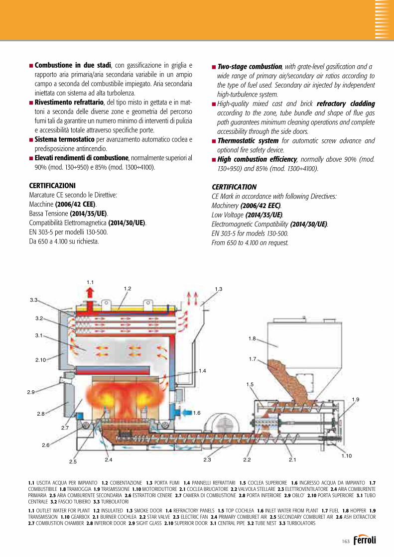
163
nTwo-stage combustion, with grate-level gasification and awide range of primary air/secondary air ratios according to the type of fuel used. Secondary air injected by independent high-turbulence system.
nHigh-quality mixed cast and brick refractory cladding according to the zone, tube bundle and shape of flue gas path guarantees minimum cleaning operations and complete accessibility through the side doors.
nThermostatic system for automatic screw advance and optional fire safety device.
nHigh combustion efficiency, normally above 90% (mod. 130÷950) and 85% (mod. 1300÷4100).
CERTIFICATIONCE Mark in accordance with following Directives: Machinery (2006/42 EEC).Low Voltage (2014/35/UE).Electromagnetic Compatibility (2014/30/UE).EN 303-5 for models 130-500.From 650 to 4.100 on request.
nCombustione in due stadi, con gassificazione in griglia e rapporto aria primaria/aria secondaria variabile in un ampio campo a seconda del combustibile impiegato. Aria secondaria iniettata con sistema ad alta turbolenza.
nRivestimento refrattario, del tipo misto in gettata e in mat-toni a seconda delle diverse zone e geometria del percorso fumi tali da garantire un numero minimo di interventi di pulizia e accessibilità totale attraverso specifiche porte.
nSistema termostatico per avanzamento automatico coclea e predisposizione antincendio.nElevati rendimenti di combustione, normalmente superiori al
90% (mod. 130÷950) e 85% (mod. 1300÷4100).
CERTIFICAZIONIMarcature CE secondo le Direttive: Macchine (2006/42 CEE).Bassa Tensione (2014/35/UE).Compatibilità Elettromagnetica (2014/30/UE).EN 303-5 per modelli 130-500.Da 650 a 4.100 su richiesta.
1.1 USCITA ACQUA PER IMPIANTO 1.2 COIBENTAZIONE 1.3 PORTA FUMI 1.4 PANNELLI REFRATTARI 1.5 COCLEA SUPERIORE 1.6 INGRESSO ACQUA DA IMPIANTO 1.7 COMBUSTIBILE 1.8 TRAMOGGIA 1.9 TRASMISSIONE 1.10 MOTORIDUTTORE 2.1 COCLEA BRUCIATORE 2.2 VALVOLA STELLARE 2.3 ELETTROVENTILATORE 2.4 ARIA COMBURENTE PRIMARIA 2.5 ARIA COMBURENTE SECONDARIA 2.6 ESTRATTORI CENERE 2.7 CAMERA DI COMBUSTIONE 2.8 PORTA INFERIORE 2.9 OBLO’ 2.10 PORTA SUPERIORE 3.1 TUBO CENTRALE 3.2 FASCIO TUBIERO 3.3 TURBOLATORI
1.1 OUTLET WATER FOR PLANT 1.2 INSULATED 1.3 SMOKE DOOR 1.4 REFRACTORY PANELS 1.5 TOP COCHLEA 1.6 INLET WATER FROM PLANT 1.7 FUEL 1.8 HOPPER 1.9 TRANSMISSION 1.10 GEARBOX 2.1 BURNER COCHLEA 2.2 STAR VALVE 2.3 ELECTRIC FAN 2.4 PRIMARY COMBURET AIR 2.5 SECONDARY COMBURET AIR 2.6 ASH EXTRACTOR 2.7 COMBUSTION CHAMBER 2.8 INFERIOR DOOR 2.9 SIGHT GLASS 2.10 SUPERIOR DOOR 3.1 CENTRAL PIPE 3.2 TUBE NEST 3.3 TURBOLATORS
1.11.2 1.3
1.4
1.5
1.6
1.7
1.8
1.9
1.102.12.22.32.42.5
2.6
2.7
2.8
2.9
2.10
3.1
3.2
3.3

164
DIMENSIONIDIMENSIONS
WM P
DATI TECNICITECHNICAL DATA
WM P 130 180 230 300 400 500 650 800 950 1300 1650 2000 2700 3400 4100 Potenzialità generatore / Generator heat input kW 139 180 237 294 395 496 650 800 950 1300 1650 2000 2700 3400 4100
Potenzialità focolare / Heat input kW 154 199 259 318 426 534 720 885 1053 1430 1830 2200 3000 3750 4550
Contenuto d’acqua / Water content dm3 450 580 740 1015 1250 1485 1920 2330 2735 4300 4970 5650 8900 10500 12100
Volume camera combustione / Combustion chamber volume m3 0,35 0,47 0,58 0,8 0,99 1,19 1,58 1,93 2,29 3,85 4,52 5,19 7,63 9,12 10,6
Lato acqua / Water side ∆p 10°C mbar 141 196 250 326 355 384 462 532 597 712 773 826 1115 1400 1680
WM P 130 180 230 300 400 500 650 800 950 1300 1650 2000 2700 3400 4100
DIMENSIONI A mm 340 340 340 450 450 450 500 500 500 560 560 560 660 660 660 DIMENSIONS B mm 950 950 950 1270 1270 1270 1560 1560 1560 2000 2000 2000 2480 2480 2480 C mm 950 1250 1550 1450 1800 2150 2050 2500 2950 3000 3500 4000 4000 4750 5500 D mm 1400 1400 1400 1800 1800 1800 2100 2100 2100 2640 2640 2640 3240 3240 3240 E mm 1740 1740 1740 2250 2250 2250 2600 2600 2600 3200 3200 3200 3900 3900 3900 F mm 1820 1520 1220 2550 2200 1850 3050 2600 2150 3450 2950 2450 4250 3500 2750 G mm 2770 2770 2770 4000 4000 4000 5100 5100 5100 6450 6450 6450 8250 8250 8250 H mm 1650 1650 1650 2000 2000 2000 2350 2350 2350 2850 2850 2850 3400 3400 3400 I mm 1700 1700 1700 1970 1970 1970 2100 2100 2100 2350 2350 2350 2800 2800 2800 L mm 750 750 750 1100 1100 1100 1200 1200 1200 1300 1300 1300 1700 1700 1700 a1-a2 DN 65 65 65 80 80 80 100 100 100 125 125 125 150 150 150 a3 DN 40 40 40 40 40 40 40 40 40 40 40 40 40 40 40 a4 DN 25 25 25 25 25 25 25 25 25 32 32 32 32 32 32 a5 DN 15 15 15 15 15 15 15 15 15 15 15 15 15 15 15 a6 mm 300 300 300 350 350 350 450 450 450 550 550 550 650 650 650 Peso caldaia / Boiler weight kg 1500 1700 1900 3200 3600 4000 5500 6000 6500 9300 11300 13800 21300 23800 26300
Key1 Boiler body2 Boiler bed3 Hopper4 Mechanical furnace
a1 Outleta2 Returna3 Draina4 Att. for heatsinka5 Att. for sink probea6 Flue connection
Legenda1 Corpo Caldaia2 Basamento3 Tramoggia4 Focolare meccanico
a1 Mandataa2 Ritornoa3 Scaricoa4 Att. dissipatore di calorea5 Att. sonda dissipatorea6 Attacco camino

165
ACCESSORI A RICHIESTA
n Potenza termica modulata in continuo: quadro elettromec-canico con accensione automatica del combustibile, modulazione di fiamma, telecontrollo, con controllo della combustione tramite sonda LAMBDA.
nRegolatore di tiraggio: mantiene costante, al valore impo-stato, il tiraggio in camera di combustione. Consta di strumento rileva-tore e farfalla motorizzata sul condotto di by-pass della batteria multi-ciclonica oppure inverter sull’aspiratore fumi. Ha un ruolo importante nel contenimento delle emissioni di polveri.
nBruciatore di accensione o pilota: consente di operare in automatico la prima accensione del combustibile solido ed è indispen-sabile per materiali con elevata umidità. Di tipo monoblocco ad una sola fiamma (~0,25 MW) può essere alimentato da gasolio o gas metano.
nSistema pulizia ad onda d’urto SBS: riduce la frequenza della pulizia del fascio tubero e mantiene nel tempo l’efficienza di scambio termico. Il sistema è composto da una serie di soffiatori ad onda d’urto applicati sulla struttura caldaia, e da un temporizzatore che gestisce il corretto funzionamento. Le polveri residue della com-bustione staccate dal banco convettivo, vengono trasportate dal flusso dei fumi e vengono decantate del sistema di filtrazione a valle della caldaia. Il sistema funziona con caldaia in marcia.
COMBUSTIBILI COMPATIBILI TIPOLOGIA
nRifiuti della prima e seconda lavorazione del legno e del sughero non trattati.
nBiomasse (Scarti vegetali di attività agricole, forestali, di prima lavorazione dei prodotti agroalimentari, sanse esauste, vinaccioli, farina di vinaccioli, residui di frutta, buccette e altri residui vegetali).
nPellets di legno.nMassima percentuale di ceneri sul combustibile secco: 2%.
GRANULOMETRIA MASSIMA AMMESSA, UMIDITÀ DEL COMBUSTIBILE,
GARANZIE SUL PROCESSO DI COMBUSTIONE E SULLE EMISSIONI AL
CAMINO, saranno definite su specifiche richieste a livello contrattuale.
ACCESSORIES AVAILABLE ON REQUEST
n Continuous heat output modulation: electromechanical panel with automatic fuel ignition, flame modulation, remote control, with control of combustion through LAMBDA probe.
nDraught regulator: this keeps the draught in the combu-stion chamber constant. It consists of a sensor device and a motor-driven throttle valve on the centrifugal dust separator assembly bypass duct or the flue gas exhaust inverter. This is important in terms of limiting dust emissions.
n Ignition or pilot burner: allows automatic initial ignition of solid fuel, essential for materials with a high moisture content. One-piece unit with one flame (~0.25 MW), can operate on oil or natural gas.
n SBS shockwave cleaning system: this reduces the required frequency for cleaning the tube bundle and ensures the heat exchanger works efficiently over time. The system is made up of a series of shockwave blowers fitted on the boiler structure, and a timer to manage correct operation. The residual dust from com-bustion removed from the tube bundle is carried by the flue gas and decants in the filtration system downstream of the boiler. The system works with the boiler operating.
COMPATIBLE FUEL TYPES
nWaste from the first and second processing of untreated wood and cork.nBiomass (plant waste from agricultural and forestry activities
and from the first processing of agricultural and food pro-ducts, depleted pomace, grape seed, grape seed flour, fruit residues, peels and other plant residues).
nWood pellets.nMaximum amount of dry fuel ash: 2%.
MAXIMUM GRAIN SIZE ALLOWED, FUEL MOISTURE CONTENT,
GUARANTEES ON THE COMBUSTION PROCESS AND EMISSIONS, will be
defined contractually, based on specific requirements.

166
Caldaia marina a tre giri di fumo per combustibili solidi, a griglia fissaThree passes water tube boiler for solid fuels, with fixed grate
WM F
Il modello WM F è una caldaia di tipo marino a tre giri di fumo per produzione di acqua calda, concepita appositamente per combustibili solidi, con struttura tubiera. Caldaia a combustibile solido a griglia fissa, idonea per la combustione di biomassa, scarti della lavorazione del legno non trattato. Le particolari soluzioni a livello di alimentazione e di griglia consentono un apporto di combustibile dosato in continuo anche per materiale grossolano e garantiscono il rispetto delle attuali norme in materia di emissioni.Gamma composta da 15 modelli con potenze utili da 130 kW a 4.100 kW.
CARATTERISTICHE PRINCIPALInPressione standard di progetto 3 bar nAlimentatore a coclea che nasce da un progetto unico
caldaia-focolare meccanico.nSottogriglia diviso in comparti stagni per una adduzione dif- ferenziata dell’aria comburente.nCamera di combustione molto ampia, dotata di volta
di riverbero e percorso invertito dei fumi per una ottimale combustione.
The WM F is a three passes water tube boiler for hot water production, designed specifically for solid fuels, with special tube structure.Fixed grate solid fuel boiler, ideal for biomass combustion, untreated wood processing scrap. The particular fuel feed and grate solutions enable a constant supply of fuel to be delivered, even when using coarse material, and ensure compliance with the current emission standards.Range consisting of 15 models with useful heat outputs from 130 kW to 4,100 kW.
MAIN FEATURESnStandard design pressure 3 bar nScrew feed assembly, the result of a single boiler-mechani-
cal burner design.nUndergrate divided into sealed compartments for differen-
tiated combustion air supply.nLarge combustion chamber with rebound vault and rever-
se flue gas flow for optimum combustion.

167
nTwo-stage combustion, with grate-level gasification and awide range of primary air/secondary air ratios according to the type of fuel used. Secondary air injected by independent high-turbulence system.
nHigh-quality mixed cast and brick refractory cladding according to the zone, tube bundle and shape of flue gas path guarantees minimum cleaning operations and complete accessibility through the side doors.
nThermostatic system for automatic screw advance and optional fire safety device.
nHigh combustion efficiency, normally above 90% (mod. 130÷950) and 85% (mod. 1300÷4100).
CERTIFICATIONCE Mark in accordance with following Directives: Machinery (2006/42 EEC).Low Voltage (2014/35/UE).Electromagnetic Compatibility (2014/30/UE).EN 303-5 for models 130-500.From 650 to 4.100 on request.
nCombustione in due stadi, con gassificazione in griglia e rapporto aria primaria/aria secondaria variabile in un ampio campo a seconda del combustibile impiegato. Aria secondaria iniettata con sistema ad alta turbolenza, indipendente.
nRivestimento refrattario, del tipo misto in gettata e in mat-toni a seconda delle diverse zone e geometria del percorso fumi tali da garantire un numero minimo di interventi di pulizia e accessibilità totale attraverso le porte laterali.
nSistema termostatico per avanzamento automatico coclea e predisposizione antincendio.nElevati rendimenti di combustione, normalmente superiori al
90% (mod. 130÷950) e 85% (mod. 1300÷4100).
CERTIFICAZIONIMarcature CE secondo le Direttive: Macchine (2006/42 CEE).Bassa Tensione (2014/35/UE).Compatibilità Elettromagnetica (2014/30/UE).EN 303-5 per modelli 130-500.Da 650 a 4.100 su richiesta.
1.1 USCITA ACQUA PER IMPIANTO 1.2 COIBENTAZIONE 1.3 PORTA FUMI 1.4 PANNELLI REFRATTARI 1.5 COCLEA SUPERIORE 1.6 INGRESSO ACQUA DA IMPIANTO 1.7 COMBUSTIBILE 1.8 TRAMOGGIA 1.9 TRASMISSIONE 1.10 MOTORIDUTTORE 2.1 COCLEA BRUCIATORE 2.2 VALVOLA STELLARE 2.3 ELETTROVENTILATORE 2.4 ARIA COMBURENTE PRIMARIA 2.5 ARIA COMBURENTE SECONDARIA 2.6 ESTRATTORI CENERE 2.7 CAMERA DI COMBUSTIONE 2.8 PORTA INFERIORE 2.9 OBLO’ 2.10 PORTA SUPERIORE 3.1 TUBO CENTRALE 3.2 FASCIO TUBIERO 3.3 TURBOLATORI
1.1 OUTLET WATER FOR PLANT 1.2 INSULATED 1.3 SMOKE DOOR 1.4 REFRACTORY PANELS 1.5 TOP COCHLEA 1.6 INLET WATER FROM PLANT 1.7 FUEL 1.8 HOPPER 1.9 TRANSMISSION 1.10 GEARBOX 2.1 BURNER COCHLEA 2.2 STAR VALVE 2.3 ELECTRIC FAN 2.4 PRIMARY COMBURET AIR 2.5 SECONDARY COMBURET AIR 2.6 ASH EXTRACTOR 2.7 COMBUSTION CHAMBER 2.8 INFERIOR DOOR 2.9 SIGHT GLASS 2.10 SUPERIOR DOOR 3.1 CENTRAL PIPE 3.2 TUBE NEST 3.3 TURBOLATORS
1.11.2 1.3
1.4
1.5
1.6
1.7
1.8
1.9
1.102.12.22.32.42.5
2.6
2.7
2.8
2.9
2.10
3.1
3.2
3.3

168
DIMENSIONIDIMENSIONS
WM F
DATI TECNICITECHNICAL DATA
WM F 130 180 230 300 400 500 650 800 950 1300 1650 2000 2700 3400 4100 Potenzialità generatore / Generator heat input kW 139 180 237 294 395 496 650 800 950 1300 1650 2000 2700 3400 4100
Potenzialità focolare / Heat input kW 154 199 259 318 426 534 720 885 1053 1430 1830 2200 3000 3750 4550
Contenuto d’acqua / Water content dm3 450 580 740 1015 1250 1485 1920 2330 2735 4300 4970 5650 8900 10500 12100
Volume camera combustione / Combustion chamber volume m3 0,35 0,47 0,58 0,8 0,99 1,19 1,58 1,93 2,29 3,85 4,52 5,19 7,63 9,12 10,6
Lato acqua / Water side ∆p 10°C mbar 141 196 250 326 355 384 462 532 597 712 773 826 1115 1400 1680
WM F 130 180 230 300 400 500 650 800 950 1300 1650 2000 2700 3400 4100
DIMENSIONI A mm 400 400 400 450 450 450 500 500 500 560 560 560 660 660 660 DIMENSIONS B mm 980 980 980 1270 1270 1270 1560 1560 1560 2000 2000 2000 2480 2480 2480 C mm 950 1250 1550 1450 1800 2150 2050 2500 2950 3000 3500 4000 4000 4750 5500 D mm 1400 1400 1400 1800 1800 1800 2100 2100 2100 2640 2640 2640 3240 3240 3240 E mm 1800 1800 1800 2250 2250 2250 2600 2600 2600 3200 3200 3200 3900 3900 3900 F mm 1950 1650 1350 2550 2200 1850 3050 2600 2150 3450 2950 2450 4250 3500 2750 G mm 2900 2900 2900 4000 4000 4000 5100 5100 5100 6450 6450 6450 8250 8250 8250 H mm 1650 1650 1650 2000 2000 2000 2350 2350 2350 2850 2850 2850 3400 3400 3400 I mm 1700 1700 1700 1850 1850 1850 1900 1900 1900 2230 2230 2230 2500 2500 2500 L mm 850 850 850 850 850 850 850 850 850 1200 1200 1200 1500 1500 1500 a1-a2 DN 65 65 65 80 80 80 100 100 100 125 125 125 150 150 150 a3 DN 40 40 40 40 40 40 40 40 40 40 40 40 40 40 40 a4 DN 25 25 25 25 25 25 25 25 25 32 32 32 32 32 32 a5 DN 15 15 15 15 15 15 15 15 15 15 15 15 15 15 15 a6 mm 300 300 300 350 350 350 450 450 450 550 550 550 650 650 650 Peso caldaia / Boiler weight kg 1600 1800 2000 3400 3800 4200 5600 6100 6600 9500 11500 14000 21500 24000 26500
Key1 Boiler body2 Boiler bed3 Hopper4 Mechanical furnace
a1 Outleta2 Returna3 Draina4 Att. for heatsinka5 Att. for sink probea6 Flue connection
Legenda1 Corpo Caldaia2 Basamento3 Tramoggia4 Focolare meccanico
a1 Mandataa2 Ritornoa3 Scaricoa4 Att. dissipatore di calorea5 Att. sonda dissipatorea6 Attacco camino

169
ACCESSORI A RICHIESTA
n Potenza termica modulata in continuo: quadro elettromec-canico con accensione automatica del combustibile, modulazione di fiamma, telecontrollo, con controllo della combustione tramite sonda LAMBDA.
nRegolatore di tiraggio: mantiene costante, al valore impo-stato, il tiraggio in camera di combustione. Consta di strumento rileva-tore e farfalla motorizzata sul condotto di by-pass della batteria multi-ciclonica oppure inverter sull’aspiratore fumi. Ha un ruolo importante nel contenimento delle emissioni di polveri.
nBruciatore di accensione o pilota: consente di operare in automatico la prima accensione del combustibile solido ed è indispen-sabile per materiali con elevata umidità. Di tipo monoblocco ad una sola fiamma (~0,25 MW) può essere alimentato da gasolio o gas metano.
nSistema pulizia ad onda d’urto SBS: riduce la frequenza della pulizia del fascio tubero e mantiene nel tempo l’efficienza di scambio termico. Il sistema è composto da una serie di soffiatori ad onda d’urto applicati sulla struttura caldaia, e da un temporizzatore che gestisce il corretto funzionamento. Le polveri residue della com-bustione staccate dal banco convettivo, vengono trasportate dal flusso dei fumi e vengono decantate del sistema di filtrazione a valle della caldaia. Il sistema funziona con caldaia in marcia.
COMBUSTIBILI COMPATIBILI TIPOLOGIA
nRifiuti della prima e seconda lavorazione del legno e del sughero non trattati.
nBiomasse (Scarti vegetali di attività agricole, forestali, di prima lavorazione dei prodotti agroalimentari, sanse esauste, vinaccioli, farina di vinaccioli, residui di frutta, buccette e altri residui vegetali).
nPellets di legno.nMassima percentuale di ceneri sul combustibile secco: 2%.
GRANULOMETRIA MASSIMA AMMESSA, UMIDITÀ DEL COMBUSTIBILE,
GARANZIE SUL PROCESSO DI COMBUSTIONE E SULLE EMISSIONI AL
CAMINO, saranno definite su specifiche richieste a livello contrattuale.
ACCESSORIES AVAILABLE ON REQUEST
n Continuous heat output modulation: electromechanical panel with automatic fuel ignition, flame modulation, remote control, with control of combustion through LAMBDA probe.
nDraught regulator: this keeps the draught in the combu-stion chamber constant. It consists of a sensor device and a motor-driven throttle valve on the centrifugal dust separator assembly bypass duct or the flue gas exhaust inverter. This is important in terms of limiting dust emissions.
n Ignition or pilot burner: allows automatic initial ignition of solid fuel, essential for materials with a high moisture content. One-piece unit with one flame (~0.25 MW), can operate on oil or natural gas.
n SBS shockwave cleaning system: this reduces the required frequency for cleaning the tube bundle and ensures the heat exchanger works efficiently over time. The system is made up of a series of shockwave blowers fitted on the boiler structure, and a timer to manage correct operation. The residual dust from com-bustion removed from the tube bundle is carried by the flue gas and decants in the filtration system downstream of the boiler. The system works with the boiler operating.
COMPATIBLE FUEL TYPES
nWaste from the first and second processing of untreated wood and cork.nBiomass (plant waste from agricultural and forestry activities
and from the first processing of agricultural and food pro-ducts, depleted pomace, grape seed, grape seed flour, fruit residues, peels and other plant residues).
nWood pellets.nMaximum amount of dry fuel ash: 2%.
MAXIMUM GRAIN SIZE ALLOWED, FUEL MOISTURE CONTENT,
GUARANTEES ON THE COMBUSTION PROCESS AND EMISSIONS, will be
defined contractually, based on specific requirements.

170
Caldaia marina a quattro giri di fumo per combustibili solidi, a griglia mobileFour passes water tube boiler for solid fuels, with mobile grate
WM GM
Il modello WM GM è una caldaia di tipo marino a quattro giri di fumo per produzione di acqua calda, concepita appositamente per combustibili solidi, con struttura tubiera conformata in funzione delle specifiche esigenze di pulibilità e corretta combu-stione. Caldaia a combustibile solido a griglia mobile, idonea per la combustione di biomassa, scarti della lavorazione del legno trattato e non trattato.Gamma composta da 15 modelli con potenze utili da 130 kW a 4.100 kW.
CARATTERISTICHE PRINCIPALInPressione standard di progetto 3 bar nAvanzamento del combustibile mediante griglia mobile incli-
nata, per un efficace controllo dello spessore del letto anche in condizioni di rammollimento e parziale fusione delle ceneri e un sicuro avviamento delle medesime alla fossa di raccolta ad evacuazione meccanica.
nAlimentatore a coclea che nasce da un progetto unico caldaia-focolare meccanico.
nSottogriglia diviso in comparti stagni per una adduzione dif- ferenziata dell’aria comburente.nCamera di combustione molto ampia e completamente
secca, dotata di volta di riverbero e percorso invertito dei fumi per una ottimale essiccazione del combustibile umido.
The WM FM is a four passes water tube boiler for hot water production, designed specifically for solid fuels, with special tube structure.Mobile grate solid fuel boiler, ideal for combustion of biomass, treated and untreated wood processing scrap. Range consisting of 15 models with useful heat outputs from 130 kW to 4,100 kW.
MAIN FEATURESnStandard design pressure 3 bar nFuel fed using a sloped mobile grate, allowing effective con-
trol of the thickness of the bed even with softening and partial melting of the ash and ensuring the latter is conveyed to the ash dump for mechanical removal.
nScrew feed assembly, the result of a single boiler-mechani-cal burner design.
nUndergrate divided into sealed compartments for differen-tiated combustion air supply.
nLarge and completely dry combustion chamber with rebound vault and reverse flue gas flow for optimum drying of damp fuel.

171
nTwo-stage combustion, with grate-level gasification and awide range of primary air/secondary air ratios according to the type of fuel used. Secondary air injected by independent high-turbulence system.
nHigh-quality mixed cast and brick refractory cladding according to the zone, tube bundle and shape of flue gas path guarantees minimum cleaning operations and complete accessibility through the side doors.
nThe bed that supports the boiler houses the combustion chamber, and is completely lined by special bricks for high-temperature combustion.
nThermostatic system for automatic screw advance and optional fire safety device.nHigh combustion efficiency, normally above 90% (mod.
130÷950) and 85% (mod. 1300÷4100).
All this is incorporated in a single compact rapid to install unit with relatively small dimensions.
CERTIFICATIONCE mark in accordance with the following Directives:Machinery (2006/42 EEC)Low Voltage (2014/35/UE)Electromagnetic Compatibility (2014/30/UE)
nCombustione in due stadi, con gassificazione in griglia e rapporto aria primaria/aria secondaria variabile in un ampio campo a seconda del combustibile impiegato. Aria secondaria iniettata con sistema ad alta turbolenza, indipendente.
nRivestimento refrattario, del tipo misto in gettata e in mat-toni a seconda delle diverse zone e geometria del percorso fumi tali da garantire un numero minimo di interventi di pulizia e accessibilità totale attraverso le porte laterali.
nIl basamento che sostiene la caldaia alloggia la camera di com-bustione ed è completamente rivestito di mattoni per una combu-stione ad elevate temperature.
nSistema termostatico per avanzamento automatico coclea e predisposizione antincendio.nElevati rendimenti di combustione, normalmente superiori al
90% (mod. 130÷950) e 85% (mod. 1300÷4100).
Tutto ciò viene realizzato in una unica blocco compatto, di com-parativamente limitato ingombro e di rapida installazione.
CERTIFICAZIONIMarcatura CE secondo le Direttive:Macchine (2006/42 CEE)Bassa Tensione (2014/35/UE) Compatibilità Elettromagnetica (2014/30/UE)
1.1 CAMINO FUMI 1.2 RITORNO ACQUA 1.3 COIBENTAZIONE 1.4 MANDATA ACQUA 1.5 FASCIO TUBIERO 1.6 TUBO CENTRALE 1.7 PORTA SUPERIORE 1.8 CAMERA DI COMBUSTIONE 1.9 PORTA INFERIORE 1.10 CAMERA A SECCO 2.1 OBLO’ 2.2 ARIA SECONDARIA 2.3 CENERI 2.4 REFRATTARIO ISOLANTE 2.5 COCLEA ESTRAZIONE CENERI 2.6 BARROTTI GRIGLIA 2.7 ARIA PRIMARIA 2.8 SISTEMA MOVIMENTAZIONE GRIGLIA 2.9 VALVOLA STELLARE 2.10 MOTOVARIARIDUTTORE 3.1 COCLEA ALIMENTAZIONE 3.2 TRASMISSIONE 3.3 AGITATORE 3.4 COMBUSTIBILE 3.5 TRAMOGGIA
1.1 CHIMNEY 1.2 INLET WATER 1.3 INSULATED 1.4 OUTLET WATER 1.5 TUBES NEST 1.6 CENTRAL PIPE 1.7 SUPERIOR DOOR 1.8 COMBUSTION CHAMBER 1.9 INFERIOR DOOR 1.10 DRY CHAMBER 2.1 SIGHT GLASS 2.2 SECONDARY AIR FAN 2.3 ASH 2.4 INSULATING REFRACTORY 2.5 COCHLEA ASH EXTRACTION 2.6 CAST IRON BARS 2.7 PRIMARY AIR FAN 2.8 HANDLING SYSTEM GRID 2.9 ROTARY VALVE 2.10 MOTOVARIATOR-GEARBOXES 3.1 FEEDING COCHLEA 3.2 TRASMISSION 3.3 AGITATOR 3.4 COMBUSTIBLE 3.5 HOPPER
1.1
1.2
1.3
1.4
1.5
1.6
1.7
1.8
1.9
1.10
2.1
2.2
2.3
2.4
2.52.62.72.8
2.9
2.10
3.13.2
3.3
3.4
3.5

172
DIMENSIONIDIMENSIONS
WM GM
DATI TECNICITECHNICAL DATA
WM F 130 180 230 300 400 500 650 800 950 1300 1650 2000 2700 3400 4100 Potenzialità generatore / Generator heat input kW 130 180 230 300 400 500 650 800 950 1300 1650 2000 2700 3400 4100
Potenzialità focolare / Heat input kW 144 200 255 333 444 554 720 885 1053 1430 1830 2200 3000 3750 4550
Contenuto d’acqua / Water content dm3 450 580 740 1015 1250 1485 1920 2330 2735 4300 4970 5650 8900 10500 12100
Volume camera combustione / Combustion chamber volume m3 0,35 0,47 0,58 0,8 0,99 1,19 1,58 1,93 2,29 3,85 4,52 5,19 7,63 9,12 10,6
Lato acqua / Water side ∆p 10°C mbar 141 196 250 326 355 384 462 532 597 712 773 826 1115 1400 1680
WM F 130 180 230 300 400 500 650 800 950 1300 1650 2000 2700 3400 4100
DIMENSIONI A mm 905 905 905 1230 1230 1230 1550 1550 1550 2000 2000 2000 2350 2350 2350 DIMENSIONS B mm 980 980 980 1270 1270 1270 1560 1560 1560 2000 2000 2000 2420 2420 2420 C mm 950 1250 1550 1450 1800 2150 2050 2500 2950 3000 3500 4000 4000 4750 5500 D mm 1395 1395 1395 1770 1770 1770 2100 2100 2100 2600 2600 2600 3250 3250 3250 E mm 2300 2300 2300 3000 3000 3000 3650 3650 3650 4600 4600 4600 5600 5600 5600 F mm 2150 2150 2150 2600 2600 2600 3500 3500 3500 4600 4600 4600 5300 5300 5300 G mm 3100 3400 3700 4050 4400 4750 5550 6000 6450 7600 8100 8600 9300 10050 10800 H mm 1700 1700 1700 2000 2000 2000 2500 2500 2500 2850 2850 2850 3400 3400 3400 I mm 1900 1900 1900 2000 2000 2000 2050 2050 2050 2550 2550 2550 3100 3100 3100 L mm 850 850 850 850 850 850 850 850 850 1200 1200 1200 1500 1500 1500 a1-a2 DN 65 65 65 80 80 80 100 100 100 125 125 125 150 150 150 a3 DN 40 40 40 40 40 40 40 40 40 40 40 40 40 40 40 a4 DN 25 25 25 25 25 25 25 25 25 32 32 32 32 32 32 a5 DN 15 15 15 15 15 15 15 15 15 15 15 15 15 15 15 a6 mm 300 300 300 350 350 350 450 450 450 550 550 550 650 650 650 Peso caldaia / Boiler weight kg 2650 3000 3400 4700 5700 6500 8600 10200 12000 18000 20600 25000 37000 41000 45000
Key1 Boiler body2 Boiler bed3 Hopper4 Mechanical furnace
a1 Outleta2 Returna3 Draina4 Att. for heatsinka5 Att. for sink probea6 Flue connection
Legenda1 Corpo Caldaia2 Basamento3 Tramoggia4 Focolare meccanico
a1 Mandataa2 Ritornoa3 Scaricoa4 Att. dissipatore di calorea5 Att. sonda dissipatorea6 Attacco camino

173
ACCESSORI A RICHIESTA
n Potenza termica modulata in continuo: quadro elettromec-canico con accensione automatica del combustibile, modulazione di fiamma, telecontrollo, con controllo della combustione tramite sonda LAMBDA.
nRegolatore di tiraggio: mantiene costante, al valore impo-stato, il tiraggio in camera di combustione. Consta di strumento rileva-tore e farfalla motorizzata sul condotto di by-pass della batteria multi-ciclonica oppure inverter sull’aspiratore fumi. Ha un ruolo importante nel contenimento delle emissioni di polveri.
nBruciatore di accensione o pilota: consente di operare in automatico la prima accensione del combustibile solido ed è indispen-sabile per materiali con elevata umidità. Di tipo monoblocco ad una sola fiamma (~0,25 MW) può essere alimentato da gasolio o gas metano.
nSistema pulizia ad onda d’urto SBS: riduce la frequenza della pulizia del fascio tubero e mantiene nel tempo l’efficienza di scambio termico. Il sistema è composto da una serie di soffiatori ad onda d’urto applicati sulla struttura caldaia, e da un temporizzatore che gestisce il corretto funzionamento. Le polveri residue della com-bustione staccate dal banco convettivo, vengono trasportate dal flusso dei fumi e vengono decantate del sistema di filtrazione a valle della caldaia. Il sistema funziona con caldaia in marcia.
COMBUSTIBILI COMPATIBILI TIPOLOGIAnRifiuti della prima e seconda lavorazione del legno e del sughero non
trattati.nBiomasse (Scarti vegetali di attività agricole, forestali, di prima lavora-
zione dei prodotti agroalimentari, sanse esauste, vinaccioli, farina di vinaccioli, residui di frutta, buccette e altri residui vegetali).
nPellets di legno.nScarti della lavorazione del legno e affini trattati (pannelli tru-
ciolati o multistrato incollati e nobilitati con resine nel tipo e quantità ammesse dalle norme sul riutilizzo dei residui). Temperatura minima di rammollimento delle ceneri: 800°C.
nMassima percentuale di ceneri sul combustibile secco: 4%.
GRANULOMETRIA MASSIMA AMMESSA, UMIDITÀ DEL COMBUSTIBILE,
GARANZIE SUL PROCESSO DI COMBUSTIONE E SULLE EMISSIONI AL CAMI-
NO, saranno definite su specifiche richieste a livello contrattuale.
ACCESSORIES AVAILABLE ON REQUEST
n Continuous heat output modulation: electromechanical panel with automatic fuel ignition, flame modulation, remote control, with control of combustion through LAMBDA probe..
nDraught regulator: this keeps the draught in the combu-stion chamber constant. It consists of a sensor device and a motor-driven throttle valve on the centrifugal dust separator assembly bypass duct or the flue gas exhaust inverter. This is important in terms of limiting dust emissions.
n Ignition or pilot burner: allows automatic initial ignition of solid fuel, essential for materials with a high moisture content. One-piece unit with one flame (~0.25 MW), can operate on oil or natural gas.
n SBS shockwave cleaning system: this reduces the required frequency for cleaning the tube bundle and ensures the heat exchanger works efficiently over time. The system is made up of a series of shockwave blowers fitted on the boiler structure, and a timer to manage correct operation. The residual dust from com-bustion removed from the tube bundle is carried by the flue gas and decants in the filtration system downstream of the boiler. The system works with the boiler operating.
COMPATIBLE FUEL TYPESnWaste from the first and second processing of untreated wood and cork.n Biomass (plant waste from agricultural and forestry activities and
from the first processing of agricultural and food products, depleted pomace, grape seed, grape seed flour, fruit residues, peels and other plant residues).
nWood pellets.nTreated wood processing scrap and similar material (glued
chipboard or multi-ply and products finished with resins of the type and in the quantity admissible according to legislation on waste reuse). Minimum temperature of softened ash: 800°C.
nMaximum percentage of ash in dry fuel: 4%.
MAXIMUM GRAIN SIZE ALLOWED, FUEL MOISTURE CONTENT,
GUARANTEES ON THE COMBUSTION PROCESS AND EMISSIONS, will be
defined contractually, based on specific requirements..

174
Recuperatore di calore da fumi di scarico turbina o motori endotermiciTurbine or engine exhaust gas heat recovery unit
PREXREC / VAPOREC
Generatori a recupero ad acqua calda o ad acqua surriscaldata che sfruttano i fumi della combustione da motori endotermici o turbine che, passando attraverso un fascio tubiero, cedono calore ad un fluido vettore.La proposta si articola sulla fornitura del corpo in pressione com-pleto di accessori comprese valvole fumi deviatrici per bloccare, in caso di necessità, l’erogazione di calore.Il dimensionamento deve essere attentamente valutato e soprat-tutto necessitano valori base dei fumi da utilizzare come, tempe-ratura, umidità, composizione, portata etc.La tipica installazione è a valle di motori endotermici o turbine per la produzione di energia elettrica ed ogni tipo di processo industriale che preveda di scaricare gas caldi in atmosfera.I recuperatori tipo PREXREC e VAPOREC offrono oltre all’intrinseca affidabilità della macchina, le migliori prestazioni e le basse perdite di carico. L’ispezionabilità lato fumi e lato acqua e la semplicità di eser-cizio unitamente ad una ridotta manutenzione necessaria, rendono il generatore una macchina adatta per i servizi più gravosi.Questi generatori possono essere dotati, in accordo alle spe-cifiche esigenze dei Clienti, di economizzatori e o batterie di preriscaldo acqua. Sono realizzati nelle versioni ad un solo passo e a due passi laddove vi siano limitate dimensioni in lunghezza e possono essere progetttati e realizzati per la produzione di acqua calda, acqua surriscaldata, vapore o olio diatermico.
Hot water or superheated water generators that recover energy from engine or turbine exhaust gases that, flowing through a tube bundle, transfer heat to a carrier fluid.The system supplied includes the pressurised recipient, complete with accessories such as exhaust gas selector valves used to stop the delivery of heat, where necessary.The units must be carefully sized based on the exhaust gas parameters, such as temperature, humidity, composition, flow-rate etc.Typically installed downstream of engines or turbines used for electricity generation and any other type of industrial process that releases hot gas into the atmosphere.The PREXREC and VAPOREC heat recovery units ensure intrinsic reliability, maximum performance and low pressure drop. The gas and water circuits can be inspected, which together with simple operation and reduced maintenance make these generators ideal for all heavy-duty applications.The generators can be fitted, based on specific customer requi-rements, with economisers and/or water pre-heating coils. Available in one-pass and two-pass versions based on the avai-lable length, and can be designed and developed for the pro-duction of hot water, superheated water, steam or diathermic oil.

175
CONTAINER
CENTRALE TERMICA PREFABBRICATA da esterno, soluzione ideale per aziende con problemi di spazio all’interno dello stabilimento. Possibilità di allestimento con la vasta gamma di generatori di calore FERROLI. Il progetto e l’esecuzione sono variabili dal tipo di esigenza ed in funzione dell’utilizzo a cui i generatori, all’interno installati, sono adibiti. L’esperienza FERROLI nel campo impianti-stico e di realizzazione di impianti chiavi in mano, ha fatto si che le centrali termiche proposte siano pienamente rispondenti alle normative vigenti ma soprattutto funzionali e complete nell’ese-cuzione. La proposta si articola su diversi tipi di esecuzione che partono da shelter con pareti di contenimento in semplice lamiera a strutture con pareti coibentate con pannelli sandwich in classe 0. A titolo esemplificativo la struttura dello shelter è così composta:nstruttura portante in acciaionblocchi d’angolo in acciaio di fusione alle estremitànpareti esterne costituite da pannelli d’acciaio corrugati in senso verticalentetto composto da pannelli d’acciaio stampati a freddo, centi-
nati per deflusso delle acque meteorichenn. 1 apertura su ogni lato lungo, costituite da telaio in tubola-re
e griglie di areazione di adeguata superficie per la potenza del generatore
npavimento in lamiera d’acciaio striatanrinforzi disposti nei punti di appoggio delle apparecchiaturenrivestimento interno delle pareti e del tetto, con pannelli san-
dwich isolanti in classe 0nn. 1 porta pedonale di accesso, cieca, con maniglione anti-
panico interno e maniglia esterna.nn. 1 portellone su una testata, a doppia antanverniciatura esterna della strutturancartellonistica di sicurezza.
PREFABRICATED HEATING PLANT for outdoor installation, the ideal solution for companies with space problems inside their facilities. The units can be configured with the vast range of FERROLI heat generators. Design and performance vary accor-ding to needs and the use that the heat generators installed insi-de are configured for. FERROLI’s experience in the development of turnkey heating systems means that these heating plants not only fully comply with the relevant standards in force, but above all are functional and complete. The products available inclu-ding different configurations ranging from shelters with simple sheet metal containers to structures with class 0 sandwich panel walls. For example, the shelter has the following composition:nsteel load-bearing structure ncast steel corner blocks at the endsnouter walls made from vertical corrugated steel panellingnroof made of cold-formed steel panels, cambered to ensure
rainwater drainagen1 opening on each long side, made from a tubular frame with aeration grills sized according to heat generator outputnstriated steel sheet metal floor nreinforcement on the equipment supportsninternal lining on the walls and roof using sandwich panels
with class 0 insulationn1 blind pedestrian access door with emergency bar on the
inside and handle on the outside.n1 double access door at one endnpainting on the outside of the structurensafety signs.
Centrale termica prefabbricata da esternoPrefabricated heating plant for outdoor installation

176
Potenzialità totale installata: 26 MW.Centrale termica completamente esonerata per 72 H da conduttore patentato.Produzione di vapore: 37 t/h.
Total capacity installed: 26 MW.Heating plant with complete exemption from certified operator requirements for 72 hours.Steam production: 37 t/h.
Progetti Realizzati - Centrali Termiche
Potenza totale installata: 6 MW.N° 2 caldaie VAPOPREX 3GN 2500 per produzione di vapore 8 t/h completamente esonerata per 72H da con-duttore patentato.
Total capacity installed: 6 MW.N° 2 VAPOPREX 3GN 2500 boilers for 8 t/h steam pro-duction with complete exemption from certified operator requirements for 72 hours.
Potenza totale installata: 4 MW.N° 2 caldaie PREXTHERM T3G F 2000 ASH 16 bar per produzione di acqua surriscaldata completamente esonerata per 72H da conduttore patentato.
Total capacity installed: 4 MW.N° 2 PREXTHERM T3G F 2000 ASH 16 bar boilers for superheated water production with complete exemption from certified operator requirements for 72 hours.

177
Completed Projects - Heating Plants
Potenza totale installata: 35 MW.Centrale termica completamente esonerata per 24 H da conduttore patentato.
Total capacity installed: 35 MW.Heating plant with complete exemption from certified operator requirements for 24 hours.
Potenza totale installata: 3,5 MW.Centrale termica con 2 caldaie a combustibile solido per la produzione di acqua calda.
Total capacity installed: 3.5 MW.Heating plant with 2 solid fuel boilers for the produc-tion of hot water.
Potenza totale installata: 15,6 MW.N° 3 caldaie PREXTHERM T3G F 5200 ASL 6 bar per produzione di acqua surriscaldata comple-tamente esonerata per 72H da conduttore patentato.
Total capacity installed: 15.6 MW.N° 3 PREXTHERM T3G F 5200 ASL 6 bar boilers for superheated water production with complete exemption from certified opera-tor requirements for 72 hours.

178
Progetti Realizzati - Centrali Termiche
Centrale termica con n° 2 caldaie per produzione di vapore 5 t/h completamente esonerate per 24 H da conduttore patentato, e da n° 3 caldaie acqua calda con potenza totale installata: 10 MW.
Heating plant with 2 boilers for steam production, 5 t/h, com-plete exemption from certified operator requirements for 24 hours, and 3 hot water boilers, total capacity installed: 10 MW.
Potenza totale installata: 15,6 MW.N° 3 PREXTEHERM T3G 5.200.
Total capacity installed: 15.6 MW.3 PREXTHERM T3G 5.200.
Potenza totale installata: 43 MW.N° 5 caldaie di cui:n° 2 PREX 3G ASH 12.000 24 H;n° 1 PREX 3G ASH 7.200 24 H;n° 2 VAPOPREX 3GN 3.000 24 H.
Total capacity installed: 43 MW.N° 5 boilers, as follows:n° 2 PREX 3G ASH 12.000 24 H;n° 1 PREX 3G ASH 7.200 24 H;n° 2 VAPOPREX 3GN 3.000 24 H.

179
Completed Projects - Heating Plants
Potenza totale installata: 15 MW.N° 5 caldaie, di cui:n° 3 PREXTHERM T3G 3400 kW;n° 2 VAPOPREX 3GF 2000.
Total capacity installed: 15 MW.N° 5 boilers, as follows:n° 3 PREXTHERM T3G 3400 kW;n° 2 VAPOPREX 3GF 2000.
Potenza totale installata: 14 MW.N° 2 caldaie VAPOPREX 3GN 6.000 18 bar.
Total capacity installed: 14 MW.N° 2 boilers VAPOPREX 3GN 6.000 18 bar.
Potenza totale installata: 9,3 MW.N° 2 caldaie PREX 3GN 4000 completamente esonerate per 72 H da conduttore patentato.
Total capacity installed: 9,3 MW.N° 2 boilers PREX 3GN 4000 with complete exemption from certified operator requirements for 72 hour.

180
Potenza totale installate: 28,3 MW.N°2 VAPOPREX 3GN 7.200;N°2 VAPOPREX 3GN 5.000.Produzione di vapore: 41,4 t/h
Total capacity installed: 28,3 MW.N°2 VAPOPREX 3 GN 7.200;N°2 VAPOPREX 3GN 5.000.Steam production: 41,4 t/h.
Potenza totale installate: 28,3 MW.N°2 VAPOPREX 3GN 7.200;N°2 VAPOPREX 3GN 5.000.Produzione di vapore: 41,4 t/h
Total capacity installed: 28,3 MW.N°2 VAPOPREX 3 GN 7.200;N°2 VAPOPREX 3GN 5.000.Steam production: 41,4 t/h.
Potenza totale installata: 25,1 MW.N° 3 VAPOPREX 3GN 7.200.Produzione di vapore: 36,8 t/h.
Total capacity installed: 25,1 MW.N°3 VAPOPREX 3GN 7.200.Steam production: 36,8 t/h.
Progetti Realizzati - Centrali Termiche

181
Completed Projects - Heating Plants
Potenza totale installata: 8,1 MW.N° 2 caldaie VAPOPREX 3GN 1750N° 1 caldaia VAPOPREX 3GN 3500Produzione di vapore: 12 t/h.
Total capacity installed: 8.1 MW.N° 2 VAPOPREX 3GN 1750N° 1 VAPOPREX 3GN 3500Steam production: 12 t/h.
Potenza totale installata: 7,3 MW.N° 1 VAPOPREX 3GN 4500;N° 1 VAPOPREX 3GN 1750.Produzione di vapore: 10,5 t/h.
Total capacity installed: 7,3 MW.N° 1 VAPOPREX 3GN 4500;N° 1 VAPOPREX 3GN 1750.Steam production: 10,5 t/h.
Potenza totale installata: 16 MW.N° 4 PREXTHERM T3G 4000.
Total capacity installed: 16 MW.N° 4 PREXTHERM T3G 4000.

FERROLI FRANCEParc TechnolandZI du Champ Dollin3 allée des Abruzzes, Bât K69 800 SAINT PRIESTtel.: 04 72 76 76 76fax: 04 72 76 76 77
Representative office in Ukraine Ferroli S.p.A. 10/17, Preobrazhenska str. 03037, Kiev, Ukraine Tel.: +38 044 537 02 39 FLJSC “FerroliBel” Republic of Belarus 222750, Minsk Region, Dzerzhinsk Province, Fanipol, 45, Zavodskaya str Tel./fax: +37 517 16 9 79 49
Moscow representative office FERROLI S.p.A. 115054, Russia, Moscow, Piatnitskaya st. 73 +7 495 788-80-35
FERROLI LIMITED Branston Ind Estate Lichfield Road Burton upon Trent DE14 3HD United Kingdom Tel. (+44) 1283 715250
FERROLI POLAND SP. Z O.O. UL. NARUTOWICZA 53 41-200 SOSNOWIEC Tel.: +48 604 516 300
FERROLI NEDERLAND B.V. Takkebijsters 62 4817 BL Breda - Netherlands +31 76 5725 725
FERROLI ROMANIA B-dul Timisoara, nr. 104E, sector 6, Bucuresti, cod postal 061334 Tel. +40 21 444 36 50
FERROLI ESPAÑA Avda. Italia, 2. Edif. Ferroli 28820 - Coslada, Madrid (ESPAÑA) Tlf.- +34 91.661.23.04
Ferroli Heating Equipment (China) Co., Ltd Address: No. 9, Jianshedong Road, Taoyuan Economic Development Zone, Heshan City, Guangdong Province Tel: +86 750 8779888 Service hot line: 400-1000-188
Qingdao Ferroli HVAC Technologies Manufactory Co. Ltd. Qingdao Ferroli Boiler & Heating Equipments Co. Ltd. Address: Jinling Industrial Zone, Chenyang District, Qingdao City, Shandong Province Tel: +86 532 66727100 Service hot line: 400-1000-188
182
Filiali / How to contact us
FERROLI RISCALDAMENTO INDUSTRIALEFERROLI INDUSTRIAL HEATING


Nell’ottica della ricerca del miglioramento continuo della propria gamma produttiva, al fine di aumentare il livello di soddisfazione del Cliente, l’Azienda precisa che le caratteristiche estetiche e/o dimensionali, i dati tecnici e gli accessori possono essere soggetti a variazione.
In accordance with the constant efforts to improve its range of products and thus raise the level of customer satisfaction, the Company stresses that the appearance and/or size, technical specifications and accessories may be subject to variation.
cod.
89C
M00
02 -
04.2
017
Ferroli spa37047 San Bonifacio (VR) Italy - Via Ritonda 78/A37047 Villanova di San Bonifacio (VR) Italy - Via M. Polo 15Italian Sales Dept. tel. +39.045.6139915/914 fax +39.045.6103490Export Sales Dept. tel. +39.045.6139928 fax +39.045.6103490www.ferroli.com
Ferroli è attenta all’ambiente. Questo catalogo è stampato su carta ecologica senza uso di cloro.Ferroli respects the environment. This catalogue has been printed on ecological paper with no use of chlorine.