Embed Size (px)
Citation preview
Development of an Ontology for a
Multi-Agent System Controlling a
Production Line
Nelson Ricardo Martins Rodrigues
Relatório Final do Trabalho de Projecto apresentado à
Escola Superior de Tecnologia e de Gestão
Instituto Politécnico de Bragança
para obtenção do grau de Mestre em
Sistemas de Informação
Setembro de 2012

Development of an Ontology for a
Multi-Agent System Controlling a
Production Line
Nelson Ricardo Martins Rodrigues
Relatório Final do Trabalho de Projecto apresentado à
Escola Superior de Tecnologia e de Gestão
Instituto Politécnico de Bragança
para obtenção do grau de Mestre em
Sistemas de Informação
Orientador:
Prof. Dr. Paulo Leitão
"Este Trabalho de Projecto não inclui as críticas e sugestões feitas pelo Júri".
Setembro de 2012


�Make everything as simple as possible, but not simpler.�
Albert Einstein.


To my family, girlfriend and friends!

Acknowledgments
This work has been �nanced by the EU Commission, within the research contract GRACE
No. NMP2-SL-2010-246203 coordinated by Univ. Politecnica delle Marche and having part-
ners SINTEF, AEA srl, Instituto Politécnico de Bragança, Whirlpool Europe srl and Siemens
AG.
I would like to thank Dr. Paulo Leitão, for his guidance, dedication, supervision and
support during the project development. Without his critical spirit and constant motivation
this project would not have been possible. I also thank the Polytechnic Institute of Bragança
for the conditions provided for carrying out this project.
I am deeply grateful to my parents, Eduardo and Alice and to my brother Tiago, which
throughout my academic career and especially at this stage remained always supporters
and motivators, for me to successfully overcome all the barriers. To my cousin Tiago that
contributed for the success of the presented solution and to all my friends which directly or
indirectly comforted me.
Finally for Mariana, the promise that I will try in the future to spend more time with
her ;).
To all my thanks.
i

Abstract
Nowadays, the industry is very demanding in terms of customized high quality products at
lower costs. Furthermore, the customers intention of having the product as soon as possible,
and companies having the restriction of time, which in this case is a crucial variable, also
increases the �nal product cost. For this reason, it becomes unacceptable the development of
solutions based on centralized implementations, which do not provide robustness, �exibility
and recon�gurability. Therefore, the implementation of multi-agent based solutions ful�l the
described requirements leading to a more �exible, robust and agile system.
This work presents the development of an important issue concerning the cooperation
between the distributed agents, since one of them only has a partial view of the system.
In this way the ontologies are crucial to guarantee a common structure of the knowledge
exchanged among the agents.
The objective of this work is the development of an ontology integrating process and
quality levels to be used to represent the knowledge exchanged in a multi-agent system solu-
tion for a production line producing washing machines. Consequently, the agents exchanging
shared knowledge will support better and more accurate decisions.
The contribution of this work comprises the implementation of a multi-agent system, the
appropriate ontology formulation as well as its implementation, which makes the integration
of an industrial production line more versatile and more customized. Naturally, with this
project, it is created a recon�gurable and highly interoperable system.
Keywords: Ontologies, Multi-Agent System, Automation, GRACE.
ii

Resumo
Hoje em dia, a indústria é muito exigente em termos de produtos personalizados de alta
qualidade a custos baixos. Além disso, a intenção dos clientes é ter o produto logo que
possível, assim as empresas têm uma limitação de tempo, que neste caso é uma variável
importante, também aumenta o custo do produto �nal.
Por esta razão, torna-se inaceitável o desenvolvimento de soluções baseadas em implemen-
tações centralizadas, que não proporcionam a �exibilidade, robustez e recon�gurabilidade.
Portanto, a implementação de soluções baseadas em multi-agente cumprem os requisitos
descritos levando a um sistema mais �exível, robusto e ágil.
Este trabalho representa o desenvolvimento de uma questão importante relativa à coop-
eração entre os agentes distribuídos, uma vez que apenas um deles tem uma visão parcial
do sistema. Desta forma, as ontologias são cruciais para garantir uma estrutura comum de
conhecimento trocadas entre os agentes.
O objectivo deste trabalho é o desenvolvimento de uma ontologia da integração de proces-
sos e qualidade a serem utilizados para representar o conhecimento trocado em uma solução
de sistema multi-agente para uma linha de produção de máquinas de lavar. Consequente-
mente, os agentes trocam conhecimento compartilhado que irão suportar decisões melhores
e mais precisas.
A contribuição deste trabalho consiste na implementação de um sistema multi-agente, a
adequada formulação da ontologia, bem como a sua implementação, o que torna a integração
de uma linha de produção industrial mais versátil e mais personalizada. Naturalmente, com
este projecto, é criado um sistema recon�gurável e altamente interoperável.
Palavras Chave: Ontologias, Sistemas Multi-Agente, Automação, GRACE.
iv

Contents
List of Acronyms . . . . . . . . . . . . . . . . . . . . . . . . . . . . . . . . . . . . xv
1 Introduction 1
1.1 Motivation and Objectives . . . . . . . . . . . . . . . . . . . . . . . . . . . . 2
1.2 Limitation of Scope . . . . . . . . . . . . . . . . . . . . . . . . . . . . . . . . 3
1.3 Document Organization . . . . . . . . . . . . . . . . . . . . . . . . . . . . . 3
2 Ontologies for Multi-agent Systems 5
2.1 Multi-Agent Systems . . . . . . . . . . . . . . . . . . . . . . . . . . . . . . . 5
2.1.1 De�nitions . . . . . . . . . . . . . . . . . . . . . . . . . . . . . . . . . 6
2.1.2 Agent Oriented versus Object Oriented Programming . . . . . . . . . 7
2.1.3 Application Domains . . . . . . . . . . . . . . . . . . . . . . . . . . . 8
2.2 Ontologies . . . . . . . . . . . . . . . . . . . . . . . . . . . . . . . . . . . . . 8
2.2.1 De�nitions . . . . . . . . . . . . . . . . . . . . . . . . . . . . . . . . . 9
2.2.2 Components . . . . . . . . . . . . . . . . . . . . . . . . . . . . . . . . 11
2.2.3 Methodologies . . . . . . . . . . . . . . . . . . . . . . . . . . . . . . . 13
2.2.4 Types of Ontologies . . . . . . . . . . . . . . . . . . . . . . . . . . . . 16
2.2.5 Ontology Languages . . . . . . . . . . . . . . . . . . . . . . . . . . . 18
2.2.6 Frameworks the Management of Ontologies . . . . . . . . . . . . . . . 20
2.2.7 Combining Ontologies and Multi-agent Systems . . . . . . . . . . . . 23
2.2.8 Existing Ontologies for Manufacturing Systems . . . . . . . . . . . . 26
3 Description of the application domain 29
v
vi CONTENTS
4 Implementation of the GRACE Multi-agent System Solution 33
4.1 Speci�cation of the Multi-agent System . . . . . . . . . . . . . . . . . . . . . 33
4.2 Implementation of the Multi-agent System . . . . . . . . . . . . . . . . . . . 38
5 Design of the GRACE Ontology Schema 49
5.1 Introduction . . . . . . . . . . . . . . . . . . . . . . . . . . . . . . . . . . . . 49
5.2 Concepts . . . . . . . . . . . . . . . . . . . . . . . . . . . . . . . . . . . . . . 51
5.3 Predicates . . . . . . . . . . . . . . . . . . . . . . . . . . . . . . . . . . . . . 54
5.4 Attributes . . . . . . . . . . . . . . . . . . . . . . . . . . . . . . . . . . . . . 57
5.5 Restrictions . . . . . . . . . . . . . . . . . . . . . . . . . . . . . . . . . . . . 59
5.6 Validation and Evaluation . . . . . . . . . . . . . . . . . . . . . . . . . . . . 61
6 Integration of the Ontology in the GRACE Multi-agent System 65
6.1 Available Solutions . . . . . . . . . . . . . . . . . . . . . . . . . . . . . . . . 65
6.2 Bean Generator Plug-in . . . . . . . . . . . . . . . . . . . . . . . . . . . . . 69
6.3 Implementation of the generated classes . . . . . . . . . . . . . . . . . . . . . 72
6.4 Usage of the GRACE Ontology . . . . . . . . . . . . . . . . . . . . . . . . . 77
7 Conclusions and Future Work 83
7.1 Conclusion . . . . . . . . . . . . . . . . . . . . . . . . . . . . . . . . . . . . . 83
7.2 Future Work . . . . . . . . . . . . . . . . . . . . . . . . . . . . . . . . . . . . 84
A GRACE Ontology Description 97
A.1 Relations or Predicates . . . . . . . . . . . . . . . . . . . . . . . . . . . . . . 97
A.1.1 Predicates versus Predicates Classes . . . . . . . . . . . . . . . . . . . 115
A.2 Attributes . . . . . . . . . . . . . . . . . . . . . . . . . . . . . . . . . . . . . 116
A.3 Constrains/Restrictions . . . . . . . . . . . . . . . . . . . . . . . . . . . . . . 123
A.4 Validation . . . . . . . . . . . . . . . . . . . . . . . . . . . . . . . . . . . . . 135
B Frameworks to Develop Agent-based Solutions 143
B.1 Comparison between Agent Development Platforms . . . . . . . . . . . . . . 143
B.2 JADE tools . . . . . . . . . . . . . . . . . . . . . . . . . . . . . . . . . . . . 144

CONTENTS vii
B.3 Jade Basics Services . . . . . . . . . . . . . . . . . . . . . . . . . . . . . . . 147

viii CONTENTS
List of Figures
2.1 Top and bottom view of the agents (adapted from [46] ). . . . . . . . . . . . 7
2.2 Main ontological components using RDF Language. . . . . . . . . . . . . . . 12
2.3 Example of a ontology concretization. . . . . . . . . . . . . . . . . . . . . . . 13
2.4 Methodology to build ontologies proposed by Noy and McGuinness [63]. . . . 14
2.5 Roles of entities involved in the ontology design. . . . . . . . . . . . . . . . . 16
2.6 Ontologies generality according to their level of dependence. . . . . . . . . . 17
2.7 Evolution of the markup languages. . . . . . . . . . . . . . . . . . . . . . . . 19
2.8 Screenshot of the OntoEdit editor. . . . . . . . . . . . . . . . . . . . . . . . 21
2.9 Screenshot of the WebODE editor. . . . . . . . . . . . . . . . . . . . . . . . 22
2.10 Screenshot of the Protégé editor. . . . . . . . . . . . . . . . . . . . . . . . . 23
2.11 The need of exchange shared knowledge in distributed systems. . . . . . . . 24
2.12 Example of a conversation using the ontology and the Fipa Protocol. . . . . 25
3.1 Production line case study. . . . . . . . . . . . . . . . . . . . . . . . . . . . . 29
3.2 Counter weight screwing station [60]. . . . . . . . . . . . . . . . . . . . . . . 30
4.1 The PTA agent behaviour model [48]. . . . . . . . . . . . . . . . . . . . . . 35
4.2 Multi-agent system architecture for production lines [49]. . . . . . . . . . . . 36
4.3 Interaction diagram for the operation execution. . . . . . . . . . . . . . . . . 37
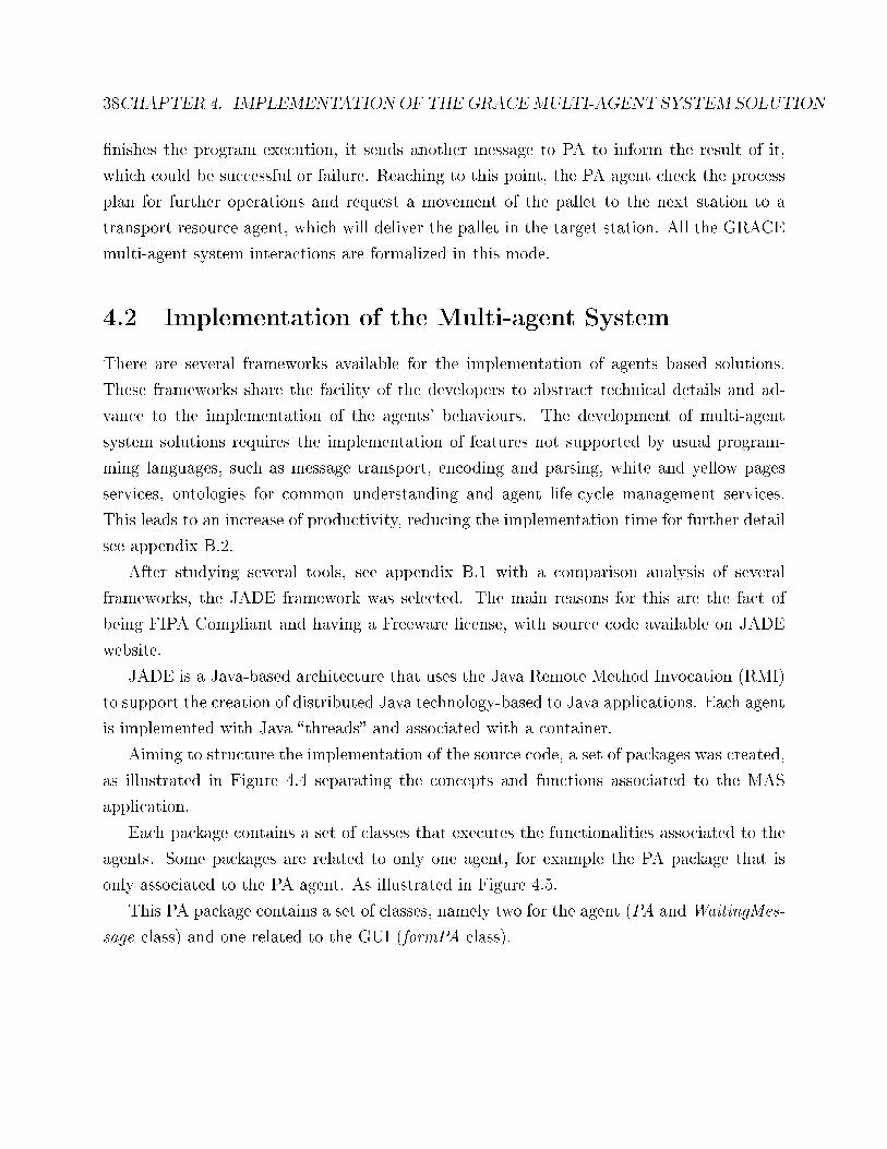
4.4 GRACE project packages. . . . . . . . . . . . . . . . . . . . . . . . . . . . . 39
4.5 Description of the PA package . . . . . . . . . . . . . . . . . . . . . . . . . . 39
4.6 Description of the package �Basic Services�. . . . . . . . . . . . . . . . . . . . 40
4.7 Classes used on GRACE to handle the interfaces with LabView applications. 44
ix
x LIST OF FIGURES
4.8 Screenshot of the IMA's GUI. . . . . . . . . . . . . . . . . . . . . . . . . . . 46
4.9 Screenshot of the Product Type Agent. . . . . . . . . . . . . . . . . . . . . . 46
4.10 Screenshot of the Product Agent. . . . . . . . . . . . . . . . . . . . . . . . . 47
4.11 Screenshot of the Resource Agent. . . . . . . . . . . . . . . . . . . . . . . . . 47
4.12 Screenshot of the Resource Agent executing an Operation after Applying
Adaptation Proced. . . . . . . . . . . . . . . . . . . . . . . . . . . . . . . . . 48
5.1 GRACE Ontology Schema. . . . . . . . . . . . . . . . . . . . . . . . . . . . . 51
5.2 Concepts of the GRACE ontology . . . . . . . . . . . . . . . . . . . . . . . . 52
5.3 The relation between the Product and ProcessPlan concepts . . . . . . . . . 55
5.4 The relation between the JournalDetails and Operation concepts . . . . . . . 56
5.5 The relations between the Resource and JournalDetails concepts . . . . . . . 56
5.6 Restrictions of predicates associated to the class �Operation�. . . . . . . . . 60
5.7 Restrictions of predicates associated to the class �Failure� . . . . . . . . . . . 61
5.8 Consistency Check for the GRACE Ontology using the Pellet tool . . . . . . 62
5.9 OWL 2 Validation Report for the GRACE ontology . . . . . . . . . . . . . . 63
5.10 Representation of class �Product� and its instances . . . . . . . . . . . . . . . 63
5.11 Representation of the �Product� and �Material� classes and their instances . 64
6.1 The Content Reference Model [7]. . . . . . . . . . . . . . . . . . . . . . . . . 66
6.2 Possible approaches for integration of the ontology in multi-agent systems. . 67
6.3 Comparison of several tools to implement the GRACE ontology. . . . . . . . 69
6.4 JADE Abstract Ontology for OntologyBeanGenerator. . . . . . . . . . . . . . 70
6.5 Partial view of the GRACE ontology with OntologyBeanGenerator Concepts 71
6.6 Screen view of OntologyBeanGenerator for JADE. . . . . . . . . . . . . . . . 72
6.7 Example some concepts generated by OntologyBeanGenerator plus Resource
Agent. . . . . . . . . . . . . . . . . . . . . . . . . . . . . . . . . . . . . . . . 73
6.8 Agents using ontologies to exchange knowledge. . . . . . . . . . . . . . . . . 77
6.9 Excerpt from the process of sending the Processplan of PA to RA agent. . . 80
6.10 ACL message exchanged between PA and RA agents. . . . . . . . . . . . . . 81
A.1 Using a predicate to relate both entities. . . . . . . . . . . . . . . . . . . . . 115
LIST OF FIGURES xi
A.2 Using the Class as predicate to relate both entities. . . . . . . . . . . . . . . 116
A.3 Representation of class �Product� and its instances. . . . . . . . . . . . . . . 136
A.4 Representation of the �Product� and �Material� classes and their instances. . 137
A.5 Representation of the �Resource� class and its instances. . . . . . . . . . . . 137
A.6 Representation of the �ProcessPlan�, �Operation� and �Resource� classes and
their instances. . . . . . . . . . . . . . . . . . . . . . . . . . . . . . . . . . . 138
A.7 MaterialFamily-Operation-Function model. . . . . . . . . . . . . . . . . . . . 139
A.8 Representation of the �MaterialFamily�, �Operation� and �Function� classes
and their instances. . . . . . . . . . . . . . . . . . . . . . . . . . . . . . . . . 139
A.9 Representation of the �ProductionOrder�, �Journal� and �JournalDetails� classes
and their instances. . . . . . . . . . . . . . . . . . . . . . . . . . . . . . . . . 141
B.1 Comparison of several Agent Platforms according to the needs. . . . . . . . 144
B.2 Structure of the Agent Management System (AMS). . . . . . . . . . . . . . . 145
B.3 Remote Management Agent. . . . . . . . . . . . . . . . . . . . . . . . . . . . 145
B.4 Graphical User Interface of the Director Facilitator. . . . . . . . . . . . . . . 146
B.5 Sni�er agent. . . . . . . . . . . . . . . . . . . . . . . . . . . . . . . . . . . . 147
B.6 Graphical User Interface of the Instrospector Agent . . . . . . . . . . . . . . 147
B.7 Agent execution cycle [7] . . . . . . . . . . . . . . . . . . . . . . . . . . . . . 148

xii LIST OF FIGURES
List of Tables
2.1 Di�erences between Databases and Ontologies [78]. . . . . . . . . . . . . . . 11
5.1 Example of GRACE ontology attributes. . . . . . . . . . . . . . . . . . . . . 58
A.1 GRACE ontology attributes. . . . . . . . . . . . . . . . . . . . . . . . . . . . 117
B.1 Behaviours provided by JADE platform. . . . . . . . . . . . . . . . . . . . . 149
xiii

xiv LIST OF TABLES
List of Acronyms
ACL Agent Communication Language
AGV Auto-guided Vehicle
AI Arti�cial Intelligence
AP Application Protocol
API Application Programming Interface
BOM Bill of Material
CNC Computer Numeric Control
DAML DARPA Agent Markup Language
EDI Electronic Data Interchange
ER Entity-Relationship
ERP Enterprise Resource Planning
FIPA Foundation for Intelligent Physical Agents
FOL First Order Logic
GRACE inteGration of pRocess and quAlity Control using multi-agEnt technology
GUI Graphical User Interface
xv
xvi LIST OF ACRONYMS
IGES Initial Graphics Exchange Speci�cation
JADE Java Agent DEvelopment Framework
JESS Java Expert System Shell
KIF Knowledge Interchange Format
MAS Multi-Agent System
MES Manufacturing Execution System
NIST National Institute of Standards and Technology
OIL Ontology Inference Layer
OOP Object Oriented Programming
OWL Web Ontology Language
RDF Resource Description Framework
RDFS Resource Description Framework Schema
RDQL RDF Data Query Language
RQL RDF Query Language
SET Standard d'Échange et de Transfert
SGML Standard Generalized Markup Language
SPARQL SPARQL Protocol and RDF Query Language
SQL Structured Query Language
STEP Standard for the Exchange of Product model data
SWRL Semantic Web Rule Language
LIST OF ACRONYMS xvii
TOVE Toronto Virtual Enterprise Ontology
UML Uni�ed Modelling Language
URI Uniform Resource Identi�er
W3C World Wide Web Consortium
XML Extensible Markup Language

xviii LIST OF ACRONYMS
Chapter 1
Introduction
Over recent years it has been noticed a strong pressure of markets demanding customized
products with higher quality at reduced costs. The manufacturing industries are then forced
to implement more intelligent, faster, modular, and �exible systems. Processes focused on
agility, �exibility and re-con�gurability were applied in a distributed manner, leaving the
traditional centralized ideology.
Nowadays, the implemented solutions are more intelligent, closer to the users, satisfying
their needs in a more rapid and e�cient way. These features make the implementation of
production control systems more di�cult, leading to a much more complex system.
The multi-agent systems (MAS) paradigm �ts perfectly into the needs of a complex and
adaptive system, where it is necessary to distribute such complexity, making the system more
�exible, while maintaining or increasing the same robustness.
Due to its inherent characteristics, distributed and autonomous agents only have a par-
tial view of the entire system, requiring the need to interact among them to exchange the
shared knowledge. In this way, the use of ontologies is crucial to guarantee a common struc-
ture of the knowledge exchanged among the distributed agents during their conversations.
With ontologies it is possible to properly share structured information without compromis-
ing the semantic issues that may exist. The sharing of information based on ontologies in
a distributed system, produces an environment very easily malleable and with highly agile
customization. Good base of knowledge representation of the factory line allows supporting
better deciding making processes, have a fairly large impact because the system can adapt
1
2 CHAPTER 1. INTRODUCTION
or �x errors without the human interaction. Clearly, the decreasing number of errors will
have a cost reduction for the manufacturing company, reducing the costs of production as
well as time of bad production, since there are no delays caused by breakdowns and badly
executed machinery. Due to easy communication and exchange of knowledge, agents have a
better knowledge base to be able to decide more accurately. In this way, the MAS solution
can create a distributed layer that provides intelligence and adaptation by distributing the
decision-making processes along the line.
1.1 Motivation and Objectives
The motivation of this work lies in understanding how to develop ontologies and how to inte-
grate, in a simple and easy manner in a multi-agent system. The opportunity to implement
an ontology for a real industrial production line, under the European FP7 GRACE (inteGra-
tion of pRocess and quAlity Control using multi-agEnt technology) (www.grace-project.org)
project, as well the problematic domain, makes this work interesting and challenging.
The main objective of this work is the development of an ontology, which integrates quality
and process control for washing machines production line. This will be posteriorly integrated
in a multi-agent system, which will control the production process in the production line.
This thesis will handle the corresponding reports of the design processes.
The described objective will comprise three main sub-objectives. The �rst sub-objective is
associated with the study of the state of the art related with the existing ontologies, practices,
languages and tools that are used to help on the development and integration of ontologies.
Brief discussions of multi-agent systems and existing ontologies in a manufacturing �eld will
be made.
The second sub-objective is related to the design of the ontology schema, which requires
the identi�cation of the domain concepts, their attributes, the relations among concepts and
relations to the associated restrictions and attributes. The validation of the designed model
and is mainly performed by the instantiation of practical examples.
The third and �nal sub-objective is related to the integration of the designed ontology
schema in a MAS solution.
During the design and implementation of the system and also the ontology model, it was
1.2. LIMITATION OF SCOPE 3
possible to present and validate these concepts by some articles published on international
conferences. Also during this stage some deliverables for the GRACE project have been
wrote.
1.2 Limitation of Scope
As referred, it is crucial a design of an ontology to deliver a common understanding on
the vocabulary used by the intelligent, distributed agents during the exchange and sharing of
knowledge. In order to control the concepts of the domain, the ontology range was restricted.
In this way, it is necessary to keep in mind that the terms and concepts used to construct
the ontology, can in another point of view, create di�erent meanings and thus a di�erent
ontology at the end. The ontology created might not be unique, but the objective is not to
create a generic solution, which can be used as several solutions for di�erent problems, but
a conceptualization for the washing machines production lines case study.
The ontology design was thought taking into consideration only the integration with
multi-agent systems, and not in the ontological philosophical subject, neither in a semantic
web purpose.
The development of the multi-agent system infrastructure is not the main issue of this
topic and it is only the recipient of the ontology development and will be used to test the
conversation among the agents using the developed ontology to represent the exchanged
shared knowledge.
1.3 Document Organization
The document is divided into 7 chapters. After this brief introduction, chapter 2 will pro-
vide a contextualization of the ontologies to address the knowledge representation and the
interoperability in distributed, heterogeneous systems. Also it gives an overview about the
methodologies and available languages to develop ontologies and the existing ontologies for
the manufacturing domain. In Chapter 3, it is described the application domain and brie�y
explained the domain that will be modelled. Chapter 4 describes the speci�cation and im-
plementation of the multi-agent system infrastructure using the JADE framework. Chapter
4 CHAPTER 1. INTRODUCTION
5 is devoted to the design of the GRACE ontology schema for production line systems, in-
tegrating process and quality control, describing very brie�y the main concepts, predicates,
attributes and restrictions, and elaborating a validation of the GRACE ontological model
by instantiating the ontology schema. Chapter 6 presents the integration of the designed
ontology in the implemented multi-agent systems infrastructure. Finally, Chapter 7 discuss
the conclusions achieved during the development process and points out some possible fu-
ture work. Additionally, two annexes detail the description of the GRACE ontology and the
frameworks available to develop agent-based solutions.
Chapter 2
Ontologies for Multi-agent Systems
The communication among distributed agents requires a common understanding of the ex-
changed knowledge during the conversation. For this purpose, terminology of the conversa-
tion has to be dominated by the agents in such environments, the knowledge of each agent
must be speci�ed for a particular domain, labelled by concept of ontology.
In this way, ontologies always end up being necessary to support the understanding within
multi-agent system. In the case of distributed computing systems like MAS there must be
some kind of consistency in the conversation of the actors involved.
This chapter discusses just that, the integration of these two worlds. First, will be in-
troduced the MAS paradigm and its application to manufacturing systems. After that, a
theoretical overview of the ontologies is presented. Also is providing some notions, identify-
ing particular components and recognize types of existing ontologies. Then, it is addressed
the design and development phases of an ontology, referring the main issues, tools and ontol-
ogy languages. At the end, the chapter surveys the existing ontologies for the manufacturing
domain.
2.1 Multi-Agent Systems
A multi-agent system is composed by many intelligent and autonomous agents, which have
the ability to communicate with each other to reach faster or with more precision to a common
5
6 CHAPTER 2. ONTOLOGIES FOR MULTI-AGENT SYSTEMS
goal. On the following sections these subjects will be presented with more deeply detail.
2.1.1 De�nitions
The multi-agent systems paradigm result from the Distributed Arti�cial Intelligence (DAI)
�eld [88],[18]. The concept of agent is neither unique nor consensual, mainly because some
attributes are more important than others. Some proposed de�nitions found in the literature
are summarized below:
• an agent is �an autonomous component that represents physical or logical objects in the
system, capable to act in order to achieve its goals, and being able to interact with other
agents, when it doesn't possess knowledge and skills to reach alone its objectives� [46].
• �an agent is a computer system that is situated in an environment and that is capable
of autonomous action in this environment in order to meet its design objectives� [88].
• �an agent is anything that can be viewed as perceiving its environment through sensors
and acting upon that environment through e�ectors� [72].
• �an agent is a computational entity that can be viewed as perceiving and acting upon its
environment, that is autonomous and that operates �exibly and rationally in a variety
of environmental circumstance� [91].
• �an agent is a persistent computation that can perceive its environment and reason
and act both alone and with other agents. The key concepts in this de�nition are
interoperability and autonomy� [75].
Agents have diverse characteristics, such as intelligence, autonomy, pro-activeness, adaptation
and social behaviour. All of them are important, but depending on the objectives, their
importance can increase or decrease. In multi-agent systems, autonomy and cooperation
have a special prominence. The autonomy can be represented as the ability to perform their
own decisions without human intervention; autonomy allows systems to perform in dynamic
environments; di�erent levels of autonomy can be speci�ed. Cooperation is the capability to
interact with each other, acting together to achieve a global system goal, or shared goals.
2.1. MULTI-AGENT SYSTEMS 7
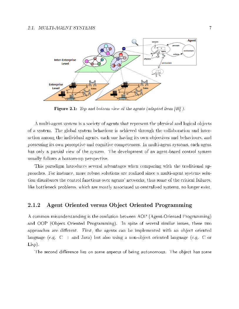
Figure 2.1: Top and bottom view of the agents (adapted from [46] ).
A multi-agent system is a society of agents that represent the physical and logical objects
of a system. The global system behaviour is achieved through the collaboration and inter-
action among the individual agents, each one having its own objectives and behaviours, and
possessing its own perceptive and cognitive competences. In multi-agent systems, each agent
has only a partial view of the system. The development of an agent-based control system
usually follows a bottom-up perspective.
This paradigm introduces several advantages when comparing with the traditional ap-
proaches. For instance, more robust solutions are realized since a multi-agent systems solu-
tion distributes the control functions over agents' networks, thus some of the critical failures,
like bottleneck problems, which are mostly associated to centralized systems, no longer exist.
2.1.2 Agent Oriented versus Object Oriented Programming
A common misunderstanding is the confusion between AOP (Agent-Oriented Programming)
and OOP (Object Oriented Programming). In spite of several similar issues, these two
approaches are di�erent. First, the agents can be implemented with an object oriented
language (e.g. C++ and Java) but also using a non-object oriented language (e.g. C or
Lisp).
The second di�erence lies on some aspects of being autonomous. The object has some
8 CHAPTER 2. ONTOLOGIES FOR MULTI-AGENT SYSTEMS
functions, which were created to be executed when requested, without any decision. Com-
paring with the agent, that has some skills to execute, this is di�erent because the agent can
think what is better to him-self and refuse that order of task execution.
Several methodologies were introduced in the literature to support the speci�cation and
engineering of multi-agent systems, such as AALAADIN [19], Tropos [9], Prometheus [68],
Agent UML [6], and GAIA [87], the last one probably being the best known methodology.
These methodologies have their principles on object-oriented programming, and present some
limitations, namely: they do not deal directly with particular modelling techniques and with
implementation issues. Particularly, and as sustained by [38], GAIA does not present a
holistic model of the execution environment to the developers, which renders inappropriate
for engineering applications with dynamic and heterogeneous environments.
2.1.3 Application Domains
The multi-agent systems technology is being applied to di�erent domains. In literature, it
can be found several examples of agent based solutions, for example in the market trad-
ing, telecommunications, healthcare, movies (e.g. in the �The Lord of the Rings�, the agent
technology was used to model individual �ghters). As other examples, Whitestein Technolo-
gies developed an agent-based solution for automatic optimisation for large-scale transport
companies and, Aerogility and Rolls Royce companies have been developed an application
to reduce the complexities of the aerospace aftermarket. IBM is also using agents to sup-
port its autonomic computing systems to increase their productivity and DaimlerChrysler
implemented a solution on their factory �oor using agents. In the aerospace �eld, NASA a
agent-based solution to balance multiple demands on its satellites. This and others industrial
applications of multi-agent systems can be found in [54][90].
2.2 Ontologies
An ontology is an agreed model, within a conceptualization of the domain of interest. An
ontology allows the de�nitions of the vocabulary in a richer manner that will support the
knowledge description, allowing restrictions on their features and properties.
2.2. ONTOLOGIES 9
Compared with the taxonomy1, ontologies represent a higher and more �exible level, and
can de�ne the semantics of the terms of a vocabulary, concepts and relations of interconnected
terms [13]. In this chapter some ontology terms and de�nitions will be presented.
2.2.1 De�nitions
The term ontology has been gradually used due to the need to represent knowledge in a
particular area, and has gained more interest with the Semantic Web advent.
The term ontology is vague and not precise. Among the several de�nitions of ontology
that can be found in the literature, the following ones can be pointed out:
• An ontology �de�nes the basic terms and relations comprising the vocabulary of a topic
area as well the rules for combining terms and relations to de�ne extensions to the
vocabulary� [61].
• An ontology is �a formal, explicit speci�cation of a shared conceptualization� [29]. In
this de�nition the terms used have the following meaning:
� �Formal� refers to the fact that the ontology should be machine readable.
� �Explicit� means that the types of concepts used, and the constraints on their use,
are explicitly de�ned.
� �Shared� re�ects that the ontology should capture consensual knowledge accepted
by the communities.
� �Conceptualization� refers to an abstract model of phenomena in the world by
having identi�ed the relevant concepts of those phenomena.
• An ontology is �a logical theory accounting for the intended meaning of a formal vocab-
ulary, i.e. its ontological commitment to a particular conceptualization of the world �
[32].
1A taxonomy is a terminology in which the terms are organized hierarchically. Each term can share arelationship between a parent and a child node (specialization / generalization) with one or more elementsof the taxonomy.
10 CHAPTER 2. ONTOLOGIES FOR MULTI-AGENT SYSTEMS
• An ontology �provides meta-information which describes the data semantics, being pos-
sible to represent knowledge and use that knowledge to communicate with various types
of entities (software agents or humans)� [17].
• An ontology can be described as �means of enabling communication and knowledge
sharing by capturing a shared understanding of terms that can be used both by humans
and programs� [44].
In spite of all the di�erent de�nitions, it is consensual that an ontology creates shared
understanding, enabling the exchange of knowledge and the capability to reuse that knowl-
edge. In other words, an ontology de�nes the vocabulary and the semantics that are used in
the communication between distributed entities, and the knowledge relating to these terms.
In the computational world, ontologies are one way to describe computationally process-
able knowledge, but also to increase communication between computers and humans. There
are three main reasons for using ontologies [79], namely:
1. Assist in communication between humans and computers.
2. Achieving interoperability between software systems.
3. Help improve the quality of design and system architecture software.
A pertinent question is the di�erence between ontologies and databases. Both ontologies
and databases provide a way to store data in a structured way. But ontologies do more,
by providing the capability for the formal description of data and rules about their context,
instead of a static way to store knowledge. As consequence, ontologies allow to deal with
incomplete data, to infer answers from current ontology data and to reveal contradictions/in-
consistencies. In such way, databases are considered when: i) the schema is small and simple,
and ii) all information is available and was not created due to a query. On the other hand,
ontologies are considered when: i) the schema is large and complex, and can be created at
query time, ii) it is possible to infer answers (i.e. query answers re�ect the schema and the
instances/data), and iii) it is necessary to deal with incomplete information.
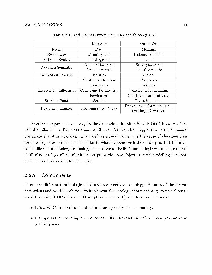
Table 2.1, summarizes the several di�erences between database and ontologies.
2.2. ONTOLOGIES 11
Table 2.1: Di�erences between Databases and Ontologies [78].
Database Ontologies
Focus Data Meaning
By the way Meaning Lost Instances optional
Notation Syntax ER diagrams Logic
Notation SemanticMinimal focus on
formal semantic
Strong focus on
formal semantic
Expressivity overlap Entities Classes
Attributes, Relations Properties
Constrains Axioms
Expressivity di�erences Constrains for integrity Constrains for meaning
Foreign key Consistence and Integrity
Starting Point Scratch Reuse if possible
Processing Engines Reasoning with ViewsDerive new Information from
existing information
Another comparison to ontologies that is made quite often is with OOP, because of the
use of similar terms, like classes and attributes. As like what happens in OOP languages,
the advantage of using classes, which de�nes a small domain, is the reuse of the same class
for a variety of activities, this is similar to what happens with the ontologies. But there are
some di�erences, ontology technology is more theoretically found on logic when comparing to
OOP also ontology allow inheritance of properties, the object-oriented modelling does not.
Other di�erences can be found in [86].
2.2.2 Components
There are di�erent terminologies to describe correctly an ontology. Because of the diverse
derivations and possible solutions to implement the ontology, it is mandatory to pass through
a solution using RDF (Resource Description Framework), due to several reasons:
• It is a W3C standard understood and accepted by the community.
• It supports the most simple sentences as well as the resolution of most complex problems
with inference.
12 CHAPTER 2. ONTOLOGIES FOR MULTI-AGENT SYSTEMS
• It is very used by the Semantic Webs communities.
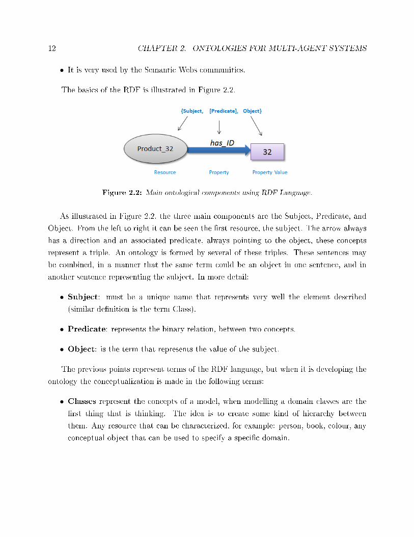
The basics of the RDF is illustrated in Figure 2.2.
Figure 2.2: Main ontological components using RDF Language.
As illustrated in Figure 2.2, the three main components are the Subject, Predicate, and
Object. From the left to right it can be seen the �rst resource, the subject. The arrow always
has a direction and an associated predicate, always pointing to the object, these concepts
represent a triple. An ontology is formed by several of these triples. These sentences may
be combined, in a manner that the same term could be an object in one sentence, and in
another sentence representing the subject. In more detail:
• Subject: must be a unique name that represents very well the element described
(similar de�nition is the term Class).
• Predicate: represents the binary relation, between two concepts.
• Object: is the term that represents the value of the subject.
The previous points represent terms of the RDF language, but when it is developing the
ontology the conceptualization is made in the following terms:
• Classes represent the concepts of a model, when modelling a domain classes are the
�rst thing that is thinking. The idea is to create some kind of hierarchy between
them. Any resource that can be characterized, for example: person, book, colour, any
conceptual object that can be used to specify a speci�c domain.
2.2. ONTOLOGIES 13
• Attributes are used to characterized a concept Data Type, because those values rep-
resent only a pre-de�ned data, like a string, integer, Boolean, etc.
• Relations are used to make an association between two resources, i.e. the predicate
from RDF language. A relation has a domain, which is the �rst concept, and the second
is the range. In this case the range is not a Data Type, but another concept.
• Instances are individuals created to specify an object of a class.
• Triple is called from the combination of the previous concepts {subject, predicate,
object}.
2.2.3 Methodologies
The development of ontologies has a strong derivation from the object-oriented design, pre-
senting some di�culties, namely the manual construction, reuse and de�nition of concepts.
When it is necessary to start modelling an ontology of any domain in concrete, the most
common way always to think as an abstract concept, and then specializing each time it is
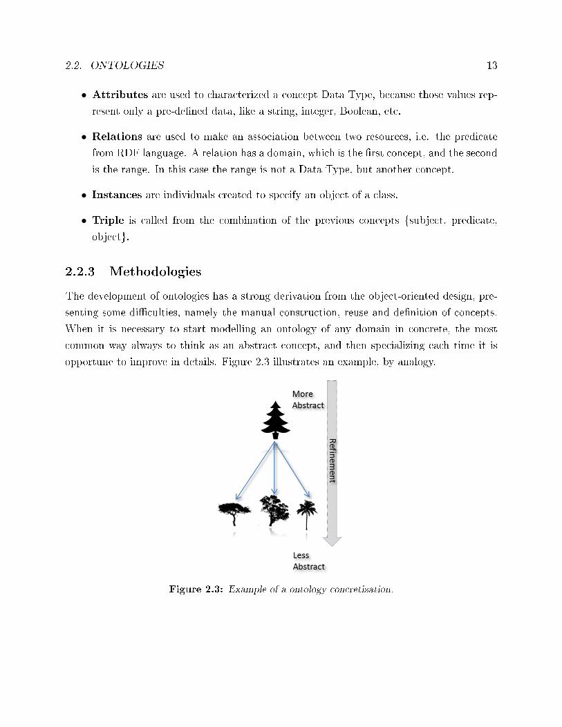
opportune to improve in details. Figure 2.3 illustrates an example, by analogy.
Figure 2.3: Example of a ontology concretization.
14 CHAPTER 2. ONTOLOGIES FOR MULTI-AGENT SYSTEMS
Here it is represented on the top, the normal and common tree, i.e. the most possible
abstract one. It starts to be more characterized passing through some re�nements and then
reaches to a concrete tree. This is the normal approach and some of these concepts are
implemented in OOP languages. In ontologies, when it is necessary to model some domains,
these approaches can be more detailed. To help on this speci�cation it is possible to follow
some guidelines.
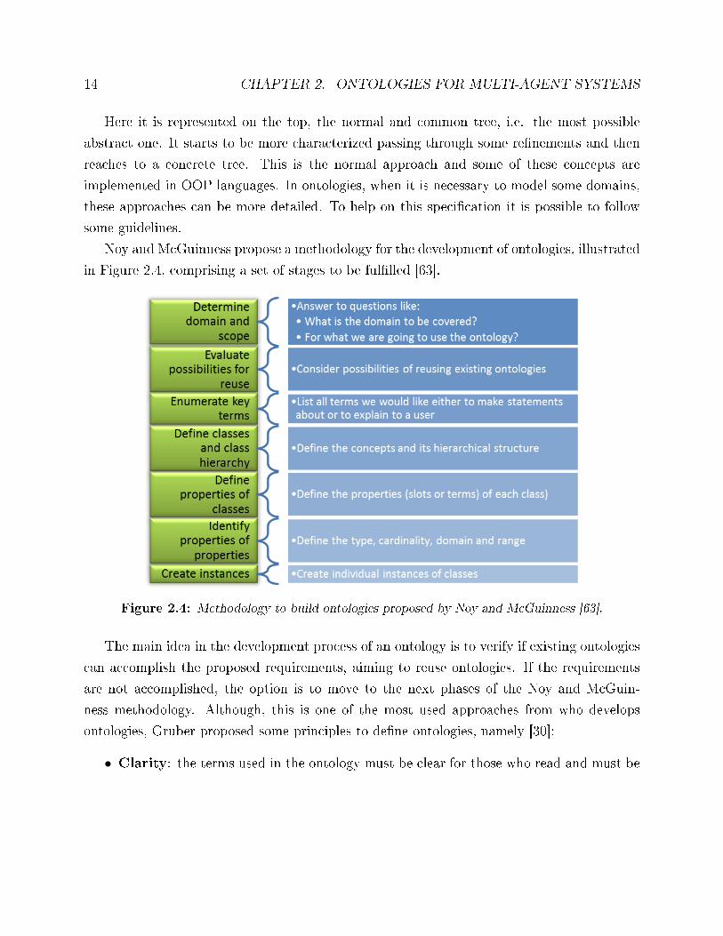
Noy and McGuinness propose a methodology for the development of ontologies, illustrated
in Figure 2.4, comprising a set of stages to be ful�lled [63].
Figure 2.4: Methodology to build ontologies proposed by Noy and McGuinness [63].
The main idea in the development process of an ontology is to verify if existing ontologies
can accomplish the proposed requirements, aiming to reuse ontologies. If the requirements
are not accomplished, the option is to move to the next phases of the Noy and McGuin-
ness methodology. Although, this is one of the most used approaches from who develops
ontologies, Gruber proposed some principles to de�ne ontologies, namely [30]:
• Clarity: the terms used in the ontology must be clear for those who read and must be
2.2. ONTOLOGIES 15
readable independently of the social situation or computational situation (implemen-
tation independent).
• Coherence: the ontology should avoid doubts and misunderstandings about the terms
used.
• Extensibility: the ontology design should support an easy expansion of the shared
vocabulary.
• Minimal encoding bias: the design must be conceived in a particular level indepen-
dent of symbol-level encoding (note that agents sharing knowledge can be implemented
in di�erent systems and using di�erent languages).
• Minimal ontological commitments: the ontology must demand a minimal ontolog-
ical compromise in order to support shared activities.
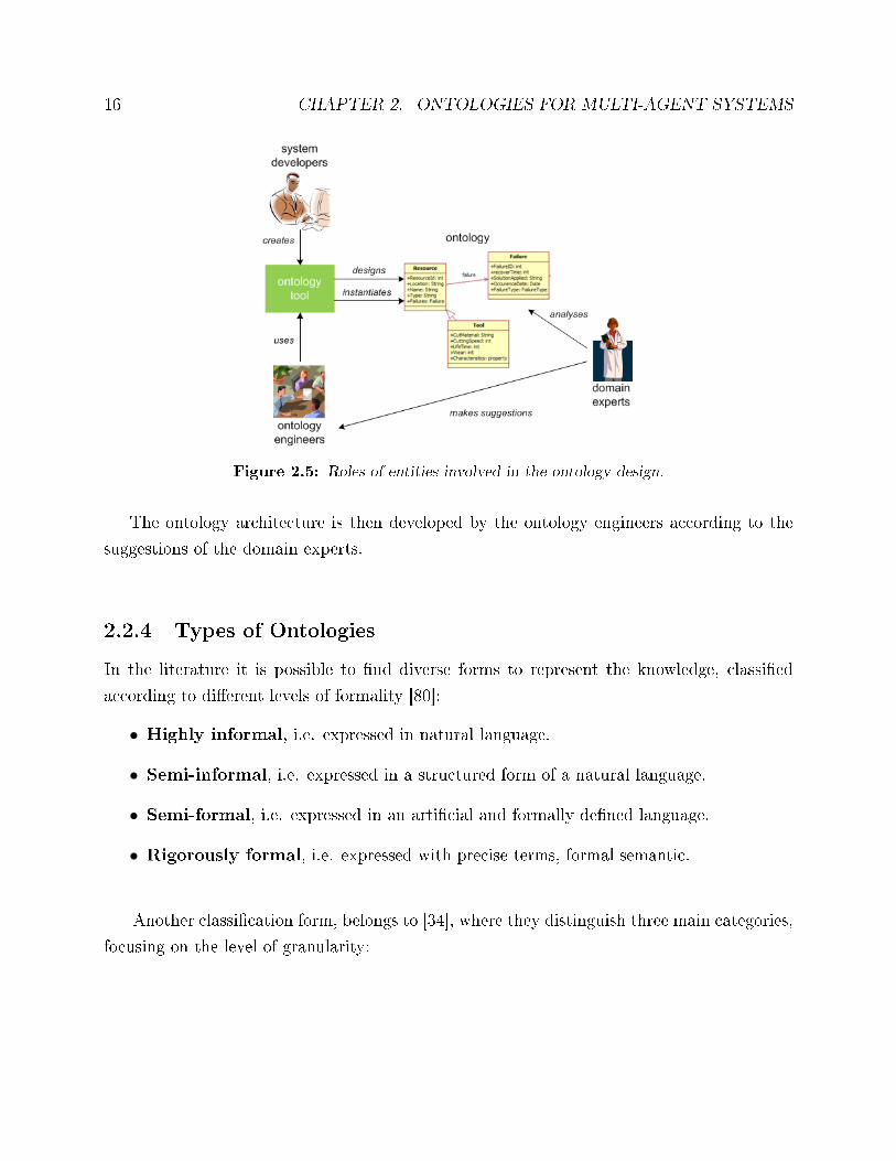
The process for the design of an ontology accounts with the contribution of di�erent
entities, each one being expert in its own domain [40]. The entities involved in the ontology
development process, as illustrated in Figure 2.5, are:
• System developers, which are responsible to provide the technological tools to sup-
port the development of the ontology.
• Ontology engineers, which are responsible for the design and implementation of the
ontology.
• Domain experts, which are entities that don't understand the technology to develop
the ontology but know reasonably well the knowledge on their domain.
16 CHAPTER 2. ONTOLOGIES FOR MULTI-AGENT SYSTEMS
Figure 2.5: Roles of entities involved in the ontology design.
The ontology architecture is then developed by the ontology engineers according to the
suggestions of the domain experts.
2.2.4 Types of Ontologies
In the literature it is possible to �nd diverse forms to represent the knowledge, classi�ed
according to di�erent levels of formality [80]:
• Highly informal, i.e. expressed in natural language.
• Semi-informal, i.e. expressed in a structured form of a natural language.
• Semi-formal, i.e. expressed in an arti�cial and formally de�ned language.
• Rigorously formal, i.e. expressed with precise terms, formal semantic.
Another classi�cation form, belongs to [34], where they distinguish three main categories,
focusing on the level of granularity:
2.2. ONTOLOGIES 17
• Terminological ontologies, which are made of lexicons that specify the terminology
which is used to represent knowledge.
• Information ontologies, which de�nes the structure of a database.
• Knowledge modelling ontologies, specify conceptualisations of the knowledge.
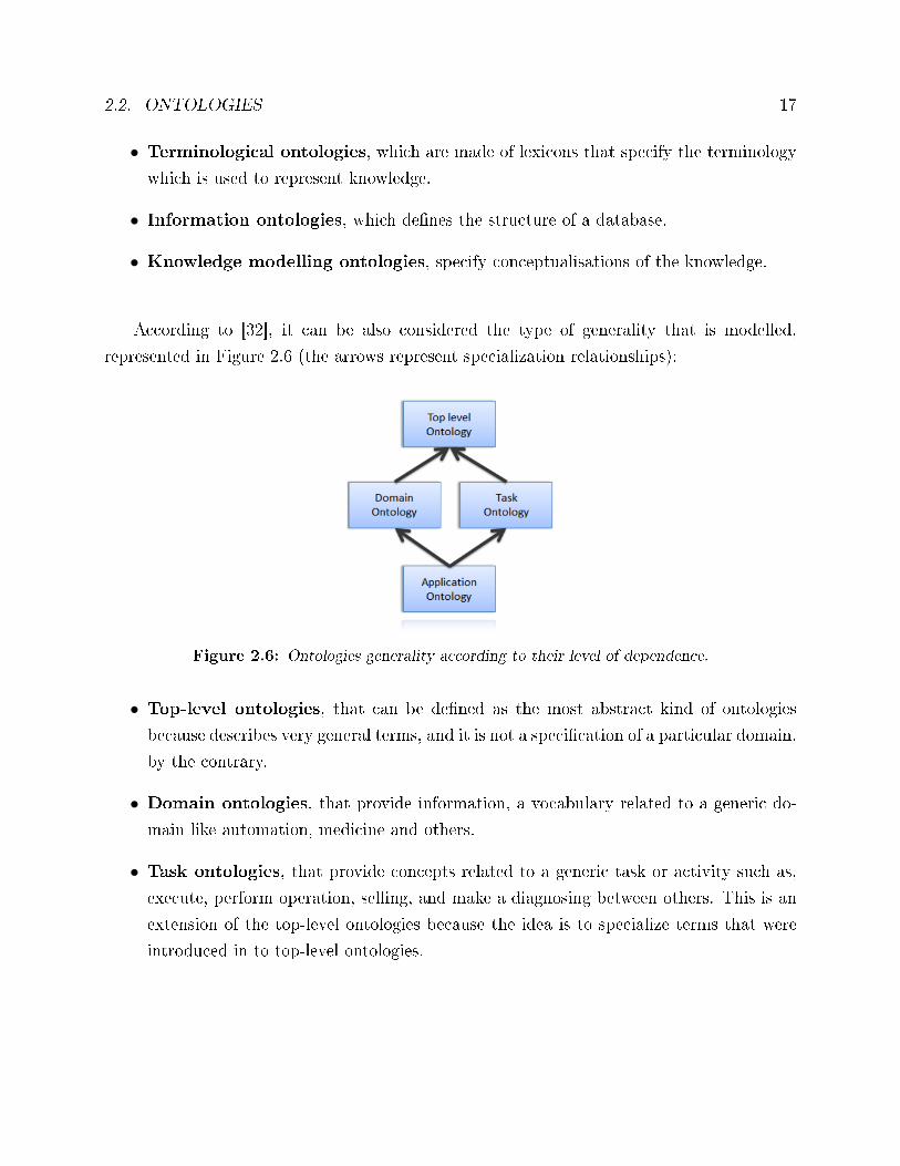
According to [32], it can be also considered the type of generality that is modelled,
represented in Figure 2.6 (the arrows represent specialization relationships):
Figure 2.6: Ontologies generality according to their level of dependence.
• Top-level ontologies, that can be de�ned as the most abstract kind of ontologies
because describes very general terms, and it is not a speci�cation of a particular domain,
by the contrary.
• Domain ontologies, that provide information, a vocabulary related to a generic do-
main like automation, medicine and others.
• Task ontologies, that provide concepts related to a generic task or activity such as,
execute, perform operation, selling, and make a diagnosing between others. This is an
extension of the top-level ontologies because the idea is to specialize terms that were
introduced in to top-level ontologies.
18 CHAPTER 2. ONTOLOGIES FOR MULTI-AGENT SYSTEMS
• Application ontologies, that provide terms inherited from domain ontologies and
task ontologies, it is very easy to think in this concept as �roles�, where domain ontolo-
gies have the domain term, and task ontology has the activity.
In this work can be considered that the ontology developed belongs to a domain ontology,
which is manufacturing domain, taking into special attention to task ontologies, because the
ontology predicates mixed with the agents' behaviours can be easily compared. In terms of
formality it can be pondered in a semi-formal language.
2.2.5 Ontology Languages
Ontologies could be developed by using a wide range of knowledge representation techniques.
KIF (Knowledge Interchange Format) is a language that allows a user to develop ontologies,
based on the �rst-order logic (FOL). It allows the inter-operation of agents with di�erent
knowledge bases, through the translation of each knowledge base into the KIF format, which
will be shared. When an agent receives a knowledge base in KIF, it converts the data into
its own internal form; when the agent needs to communicate with another agent, it maps its
internal data structures into KIF.
Ontolingua [16] is the best-known KIF ontology, intending to provide a common platform
in which ontologies developed by di�erent groups can be shared [87]. Ontolingua consists on:
• A library of ontologies, expressed in the Ontolingua ontology de�nition language, which
is based on KIF.
• A set of tools for editing and analysing the ontologies.
A set of translators for converting Ontolingua sources into forms acceptable to imple-
mented knowledge representation systems.
Nowadays, there are several languages to describe ontologies, but the most used language
is OWL (Web Ontology Language), which was inherited from XML.
The Resource Description Framework (RDF)[45] is another language used to develop
ontologies based on the markup languages, e.g. the Standard Generalized Markup Language
(SGML) and the eXtensible Markup Language (XML). Since XML is a declarative language,
2.2. ONTOLOGIES 19
being quite limited, RDF appears to overcome these limitations, e.g. in terms of relations.
RDF is used for representing information about resources on the web, thus constituting a
basic ontology language. In RDF, the statements used to describe resources are represented
as triples, consisting of a subject, predicate and object, i.e. {S, P, O}.
The RDF S (Resource Description Framework Schema) is a semantic extension of RDF,
namely by extending the RDF vocabulary to allow describing taxonomies of classes and
properties, supporting the demand to create a schema. It provides mechanisms for describing
groups of related resources and the relationships between these resources. These resources
are used to determine characteristics of other resources, such as the domains and ranges of
properties.
The Web Ontology Language (OWL)[84] mentioned above is another markup language
that semantically extends RDF and RDFS is derived from the DAML + OIL (DARPA Agent
Markup Language - Ontology Inference Layer)[36]. OWL has a rich set of modelling construc-
tors, o�ering improved pre-de�ned templates, e.g. supporting the inclusion of restrictions in
the concepts and predicates. Note that none of the other previous languages o�er this kind
of feature. Additionally, OWL provides a more expressive manner to represent knowledge,
i.e. it is possible to de�ne a model with more and better semantic value. This allows to
overcome the lack in Uni�ed Modelling Language (UML), since in UML it is not possible to
represent this as clearly expressive as in OWL.
Figure 2.7 illustrates the evolution of markup languages used to express ontologies, since
the SGML to OWL.
Figure 2.7: Evolution of the markup languages.
Other techniques can be used for the knowledge representation, namely UML, used in
software engineering and ER (Entity-relationship) diagrams, used in databases. These tech-
niques allow a di�erent modelling perspective due to the high abstraction level.
The selection of the proper language to formalize the structure of the knowledge should
take into consideration some important issues. The �rst one is that arti�cial intelligence based
languages (i.e. KIF and markup languages) are better suited to represent and implement
20 CHAPTER 2. ONTOLOGIES FOR MULTI-AGENT SYSTEMS
ontologies than UML and ER diagrams, allowing to introduce more semantically descriptions.
Secondly, languages based on XML are better suited to support the exchange of ontologies
between applications. At last, from the set of markup languages, the OWL is the one that
provides the most diverse capabilities for description because it has all the characteristics of
a markup language and also the reasoning layer that allows representing an ontology in a
more expressive manner.
2.2.6 Frameworks the Management of Ontologies
The development of ontologies is a complex task that requires the support of proper frame-
works which assist the creation or manipulation of ontologies and are able to express ontolo-
gies in one of many ontology languages.
Examples of relevant criteria for choosing an ontology editor are:
• The degree to which the editor abstracts from the actual ontology representation lan-
guage used for persistence.
• The visual navigation possibilities within the knowledge model.
• The incorporation of methodologies and languages, in an easy way.
• The ability to import and export foreign knowledge representation languages for ontol-
ogy matching.
• The licensing costs of the ontology editor.
The use of these tools may lead to an easier ontological learning and also a more produc-
tive task in the design of ontologies, supporting the concurrent work of the ontology engineers
and the domain experts.
Several frameworks are currently available, namely OntoEdit [76], WebODE [14], Protégé
[24] and Hozo [41].
OntoEdit, based on CommonKADS [73], is an ontology editor that has been developed
to support the development and maintenance of ontologies through a methodology-guided
approach. It provides the capability to develop ontologies with the help of inference and be
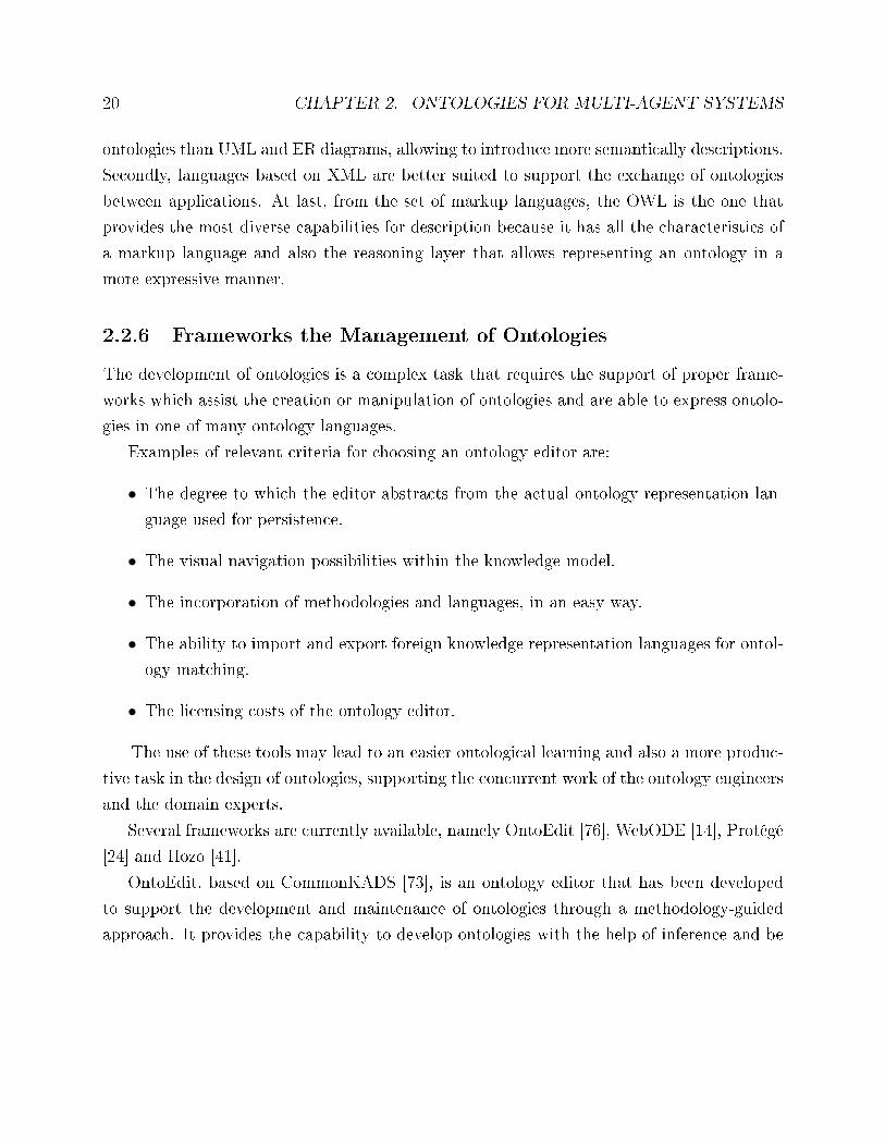
2.2. ONTOLOGIES 21
extensible through a plug-in structure. Figure 2.8 illustrates a screenshot of the OntoEdit
tool.
Figure 2.8: Screenshot of the OntoEdit editor.
This tool permits the fast development and the possibility to perform di�erent levels of
analysis, supported by the graph schemas visualization. OntoEdit is very widely used for
reasoning and evaluation phases, and can be used also in online mode.
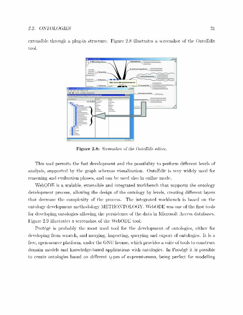
WebODE is a scalable, extensible and integrated workbench that supports the ontology
development process, allowing the design of the ontology by levels, creating di�erent layers
that decrease the complexity of the process. The integrated workbench is based on the
ontology development methodology METHONTOLOGY. WebODE was one of the �rst tools
for developing ontologies allowing the persistence of the data in Microsoft Access databases.
Figure 2.9 illustrates a screenshot of the WebODE tool.
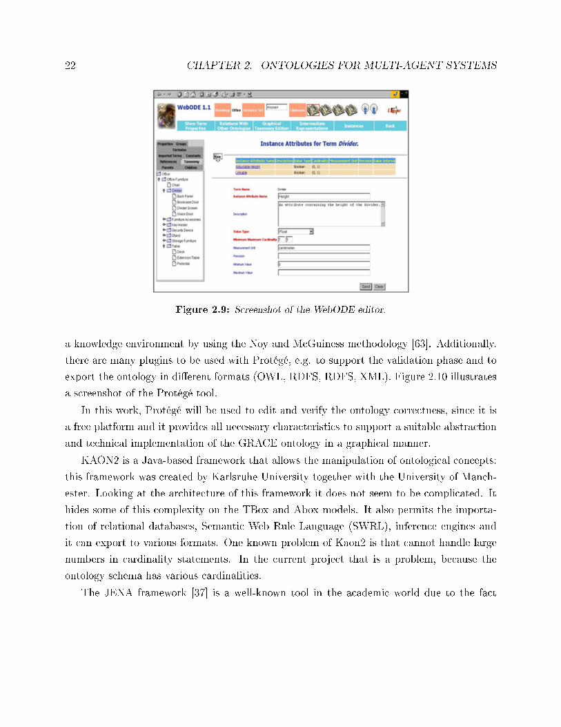
Protégé is probably the most used tool for the development of ontologies, either for
developing from scratch, and merging, importing, querying and export of ontologies. It is a
free, open-source platform, under the GNU license, which provides a suite of tools to construct
domain models and knowledge-based applications with ontologies. In Protégé it is possible
to create ontologies based on di�erent types of expressiveness, being perfect for modelling
22 CHAPTER 2. ONTOLOGIES FOR MULTI-AGENT SYSTEMS
Figure 2.9: Screenshot of the WebODE editor.
a knowledge environment by using the Noy and McGuiness methodology [63]. Additionally,
there are many plugins to be used with Protégé, e.g. to support the validation phase and to
export the ontology in di�erent formats (OWL, RDFS, RDFS, XML). Figure 2.10 illustrates
a screenshot of the Protégé tool.
In this work, Protégé will be used to edit and verify the ontology correctness, since it is
a free platform and it provides all necessary characteristics to support a suitable abstraction
and technical implementation of the GRACE ontology in a graphical manner.
KAON2 is a Java-based framework that allows the manipulation of ontological concepts;
this framework was created by Karlsruhe University together with the University of Manch-
ester. Looking at the architecture of this framework it does not seem to be complicated. It
hides some of this complexity on the TBox and Abox models. It also permits the importa-
tion of relational databases, Semantic Web Rule Language (SWRL), inference engines and
it can export to various formats. One known problem of Kaon2 is that cannot handle large
numbers in cardinality statements. In the current project that is a problem, because the
ontology schema has various cardinalities.
The JENA framework [37] is a well-known tool in the academic world due to the fact
2.2. ONTOLOGIES 23
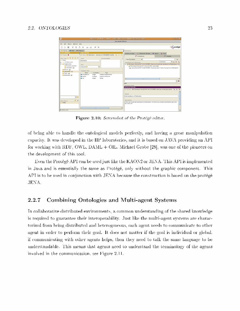
Figure 2.10: Screenshot of the Protégé editor.
of being able to handle the ontological models perfectly, and having a great manipulation
capacity. It was developed in the HP laboratories, and it is based on JAVA providing an API
for working with RDF, OWL, DAML + OIL. Michael Grobe [28], was one of the pioneers on
the development of this tool.
Even the Protégé API can be used just like the KAON2 or JENA. This API is implemented
in Java and is essentially the same as Protégé, only without the graphic component. This
API is to be used in conjunction with JENA because the construction is based on the protégé
JENA.
2.2.7 Combining Ontologies and Multi-agent Systems
In collaborative distributed environments, a common understanding of the shared knowledge
is required to guarantee their interoperability. Just like the multi-agent systems are charac-
terized from being distributed and heterogeneous, each agent needs to communicate to other
agent in order to perform their goal. It does not matter if the goal is individual or global,
if communicating with other agents helps, then they need to talk the same language to be
understandable. This means that agents need to understand the terminology of the agents
involved in the communication, see Figure 2.11.
24 CHAPTER 2. ONTOLOGIES FOR MULTI-AGENT SYSTEMS
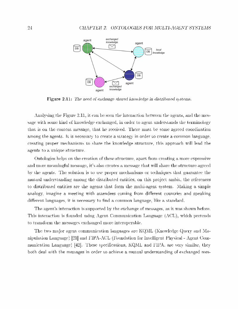
Figure 2.11: The need of exchange shared knowledge in distributed systems.
Analysing the Figure 2.11, it can be seen the interaction between the agents, and the mes-
sage with some kind of knowledge exchanged, in order to agent understands the terminology
that is on the content message, that he received. There must be some agreed coordination
among the agents. It is necessary to create a strategy in order to create a common language,
creating proper mechanisms to share the knowledge structure, this approach will lead the
agents to a unique structure.
Ontologies helps on the creation of these structure, apart from creating a more expressive
and more meaningful message, it's also creates a message that will share the structure agreed
by the agents. The solution is to use proper mechanisms or techniques that guarantee the
mutual understanding among the distributed entities, on this project ambit, the references
to distributed entities are the agents that form the multi-agent system. Making a simple
analogy, imagine a meeting with attendees coming from di�erent countries and speaking
di�erent languages, it is necessary to �nd a common language, like a standard.
The agent's interaction is supported by the exchange of messages, as it was shown before.
This interaction is founded using Agent Communication Language (ACL), which pretends
to transform the messages exchanged more interoperable.
The two major agent communication languages are KQML (Knowledge Query and Ma-
nipulation Language) [21] and FIPA-ACL (Foundation for Intelligent Physical - Agent Com-
munication Language) [42]. These speci�cations, KQML and FIPA, are very similar, they
both deal with the messages in order to achieve a mutual understanding of exchanged mes-
2.2. ONTOLOGIES 25
sages using speech act theory [74]. The KQML is the �rst best-known language due to the
fact that is the �rst that emerged, compared with FIPA. At its foundation it supports two
di�erent contexts, a formalization of the message format and a message-handling protocol
[21], [18].
The FIPA protocol o�ers something more, such as protocols. That intends to describe
di�erent interactions. FIPA consequently provides several protocols of interactions, each
representing di�erent conversation acts, such as requests, information and so on. A quite
usual protocol is contract-net, which provides the interactions in the conversation between
sellers and buyers [42]. Both speci�cations are similar in some aspects and di�erent on the
concepts, actually FIPA-ACL uses layers of KQML and adding one more, to provide a more
transparent layer of conversations among the agents. Figure 2.12, represents one example of
a FIPA conversation in this case using a Query performative.
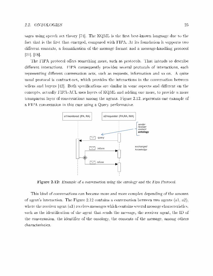
Figure 2.12: Example of a conversation using the ontology and the Fipa Protocol.
This kind of conversations can became more and more complex depending of the amount
of agent's interaction. The Figure 2.12 contains a conversation between two agents (a1, a2),
where the receiver agent (a1) receives messages which contains several message characteristics,
such as the identi�cation of the agent that sends the message, the receiver agent, the ID of
the conversation, the identi�er of the ontology, the contents of the message, among others
characteristics.
26 CHAPTER 2. ONTOLOGIES FOR MULTI-AGENT SYSTEMS
2.2.8 Existing Ontologies for Manufacturing Systems
Ontologies are used in several domains, among others in the manufacturing �eld, which is the
domain of this work. This can be con�rmed in [65] and [66], which refers that the ontologies
are currently used on agents to act as knowledge-base. In the literature, several ontolo-
gies addressing the manufacturing domain were proposed in the last years by the research
community.
The EU FP6 PABADIS'PROMISE (Plant Automation based on Distributed System
Product Oriented Manufacturing Systems for Re-Con�gurable Enterprises) project proposed
a reference meta-ontology for manufacturing [20]. This ontology is very generic where each
de�nition attempts to be more abstract and wide-ranging, covering a bigger domain. ADA-
COR (ADAptive holonic COntrol aRchitecture for distributed manufacturing systems)[47]
de�nes an ontology for manufacturing control domain, which was formalized with the DOLCE
(Descriptive Ontology for Linguistic and Cognitive Engineering) language [8].
MASON (Manufacturing's Semantics Ontology) introduces an ontology with the same
objectives, but is expressed with the OWL language in order to unify the ontologies using
cognitive architectures, leaving to an implementation of a generic manufacturing ontology
[50].
Other attempts to establish generic manufacturing ontologies are the NIST's description
of shop data model [56], the Automation Objects [67], OOONEIDA focusing on the infras-
tructure of automation components by applying the semantic web technologies [83], and
TOVE (Toronto Virtual Enterprise Ontology) that describes an ontology for virtual enter-
prise modelling [22]. The ISO 15926 standard [5] aims to support the integration of industrial
automation systems, being developed by an ontology taking into account diverse variables,
including the space and time.
An ontology for decentralized production control based on standard ANSI / ISA-95 was
developed to work with Web services [26]. Some of the most used items and methods chosen
on the creation of a manufacturing ontology, are described in [89]. The creation of an archi-
tecture using SOA (Service-Oriented Architecture) on industrial machinery was developed,
taking in consideration the manufacture process management system based on the use of
ontologies [55]. Inside of the PABADIS'PROMISE's domain a project was developed [77] to
2.2. ONTOLOGIES 27
turn more interoperable the languages to agent's interaction. Concept for seamless interac-
tion in a distributed heterogeneous manufacturing environment was solved with a common
ontological model. A more theoretical project is concerned with the connectionism [15], how
it was achieved to an ontological solution that �xed the problems in a manufacturing do-
main, how are made the ontological connections between entities. A methodology to enforce
the relation between MES (Manufacturing Execution Systems) and shop-�oor control was
established using meta-ontologies and one of the multi-agent system methodologies, namely
GAIA approach [25]. It was proposed on [23] a manufacturing navigation platform, which
allow the ontology-based process modelling and the ontology generation support by text
mining. Protégé ontology can be analysed on [85], which pretend to support an approach
which can identify what kinds of manufacturing knowledge the di�erent design decisions need.
ManuHub: A Semantic Web System for Ontology-Based Service Management in Distributed
Manufacturing Environments [11] is very dynamic framework, which takes all bene�ts of
technology such as services, semantic, mapping and apply them on the manufacturing envi-
ronment. The project OntoMaDa [70] aims to facilitate the exchange of experimental data,
because it does not exist a standard data model for manufacturing processes for this kind of
purpose. Nowadays the goal is to create more automatic ontologies, created and manipulated
on-�y by the systems. Unfortunately, it needs the human hand, called semi-automatic, [62]
it describes the mapping and the similarity computation to make this more interoperable.
Other ontologies addressing more speci�c domains in the manufacturing �eld were pro-
posed, such as the design of ontologies for �exible manufacturing systems [82], for transport
systems [57], for assembly lines control [12], for agent-based recon�guration of production
processes [1], for rent-a-car businesses [3] and for supply chain and logistic planning [2].
FRISCO is a manufacturing ontology reference that supports the organization of knowledge
in automotive supply chains [35].
The problem here is to �nd the ontology that perfectly �ts on the pre-requisites established
for the GRACE production line domain, since some described ontologies are generic and
others focus particular and speci�c application domains. The idea is to take the insights of
several manufacturing ontologies, and particularly from PABADIS'PROMISE and ADACOR,
and design a new ontology for the agent-based system integrating process and quality control
in production lines, that will be generic enough within the boundaries of the problem speci�cs.

28 CHAPTER 2. ONTOLOGIES FOR MULTI-AGENT SYSTEMS
As an example, ADACOR ontology already de�nes several entities that can be used in the
GRACE ontology. Since these entities are de�ned by their role on the multi-agent system it
is very easy to complement with ontological concepts, very similar to PABADIS'PROMISE
and ADACOR, for covering the GRACE particular domain.
Chapter 3
Description of the application domain
In this work, the ontology conceptualization is based on the manufacturing �eld and partic-
ularly production lines producing washing machines, which is the case study of the GRACE
project. Due to con�dentiality reasons, the description of the production line is not described
in detail.
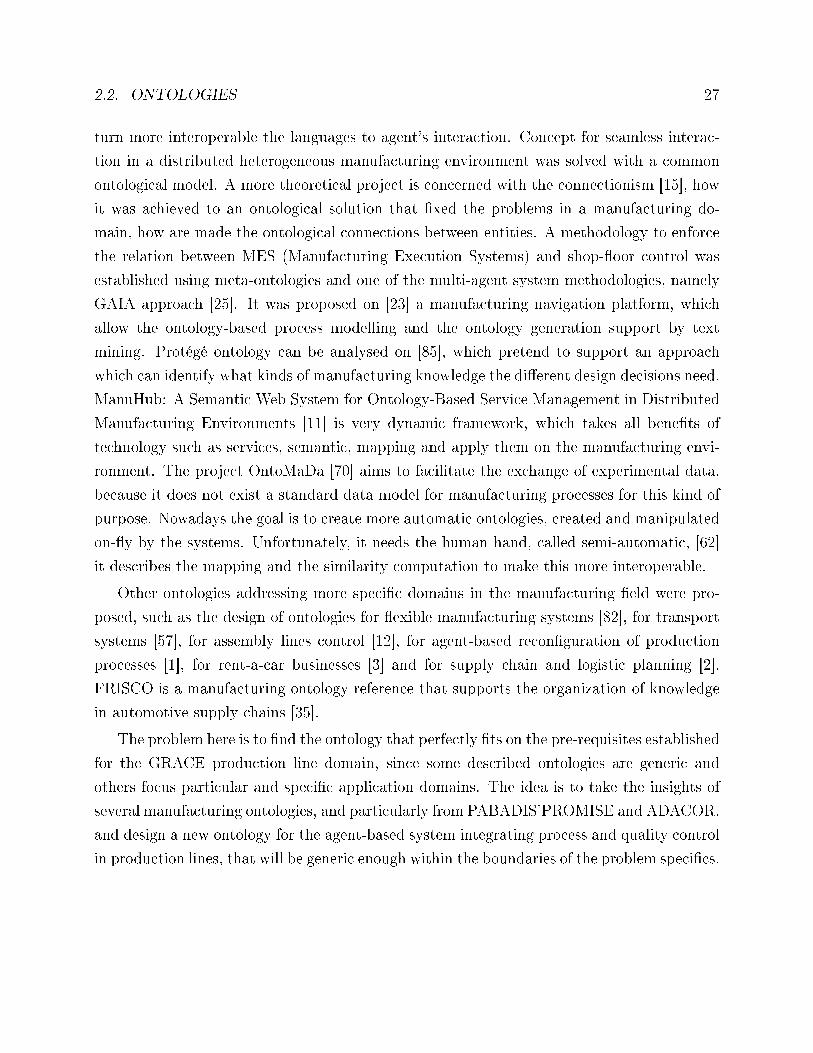
A Production line is a set of sequential work stations established along a line, aiming
to realize operations (processing, assembly, quality control, etc.) to make a �nished product,
as illustrates the Figure 3.1.
Figure 3.1: Production line case study.
The production line case study is actually composed by two parallel lines, which inter-
29
30 CHAPTER 3. DESCRIPTION OF THE APPLICATION DOMAIN
section in the middle. Thus, a machine, may or may not end up on a di�erent line of where
it started.
There are several types of resources identi�ed in the line, each one having a di�erent
purpose. These resources are automated processes, or physical resources, such as product
components or manufacturing stations, complementing among themselves to create a �nal
product. For instance, some of the processes and physical resources are [60]:
• Prefabrication of sub-systems (drum, tub, cabinet).
• Assembly of the WM sub-systems (drum, tub, washing unit, cabinet, front panel, elec-
tronic board, etc.).
• Function to execute (assembly, screwing, etc.).
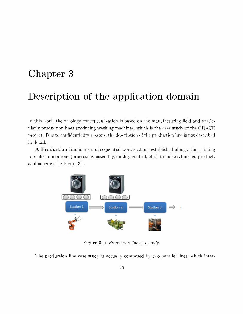
The screwing station, illustrated in Figure 3.2 is an example of a station disposed along
the production line.
Figure 3.2: Counter weight screwing station [60].
Each station performs the operation only at one machine at a time. Thereby there is a
relation one-to-one in terms of product versus station. There is a pre-de�ned sequence of
31
operations de�ning the process plan, which depends on the washing machine model. The
production line has di�erent implementation procedures, because there are di�erent washing
machines types of models.
Each pallet transporting the product being produced, is equipped with a programmable
memory named moby, and has a unique identi�er. Whenever a pallet arrives to a station,
it is identi�ed through a moby reader. Along the production line the moby installed in the
pallet is collecting some relevant information from processes that are being executed, until it
reaches the �nal testing area.
Along the production line, there are some special stations: quality control stations and
repair stations, which are located through the line. These stations have mechanisms to test
di�erent components, di�erent measurements of the washing machine components, vibration
measurements, among others. If it is ensured that the quality control stations detect any
irregularity in the implementation of the previous processes, the operator, on the repair
stations, is able to take the appliance out of the production line and work on it in order to
repair it. This happens because those anomalies are reported during its production process.
So this line is a great challenge for this project implementation since it is:
• robust, because it has a fairly number of output machines;
• �exible because a machine can be performed by di�erent stations accordingly to di�er-
ent lines.

32 CHAPTER 3. DESCRIPTION OF THE APPLICATION DOMAIN
Chapter 4
Implementation of the GRACE
Multi-agent System Solution
This chapter brie�y describes the speci�cation and implementation of the multi-agent systems
infrastructure for the described case study.
4.1 Speci�cation of the Multi-agent System
The GRACE MAS architecture was inspired in some MAS architectures [10], [47] but taking
into consideration some particularities of the case study. The development process followed
main steps:
• The identi�cation of the types of agents and their roles and functions.
• The speci�cation of individual behaviours (by using a formal language, namely the
Petri nets formalism that is suitable to model dynamic, concurrent behaviours).
• The speci�cation of the interaction patterns and cooperation/coordination mechanisms
(by using Uni�ed Modelling Language (UML) sequence diagrams and communication
diagrams) for modelling the overall behaviour of the multi-agent system that emerges
from the interactions among its individuals.
• Implementation using an agent development framework.
33
34CHAPTER 4. IMPLEMENTATIONOF THEGRACEMULTI-AGENT SYSTEM SOLUTION
The GRACE MAS considers the distribution of the manufacturing functions by several
agents, each one having a speci�c process to control [49]:
• Product Type Agents (PTA), represent the catalogue of products/parts that canbe produced by the production line and contains the process and product knowledge
required to produce the product, namely the product structure and the process plan.
The PTA agents, as well the IMA agents, don't act at the operational execution level
but instead in an higher level of control without hard real-time constraints.
• Product Agents (PA), manage the production of product instances in the plant/pro-
duction line (e.g., washing machines and drums). They hold a process plan to produce
the product and interact with the RA agents for the process and quality control.
• Resource Agents (RA), are related to the physical resources of the production line,
such as robots, quality control stations and operators. They manage the execution of
their production/testing/transportation/assembly operations in the production line.
• Independent Meta Agents (IMA), introduce a kind of hierarchy in the decentral-
ized system, allowing the implementation of global supervisory control and optimized
planning and decision-making mechanisms, e.g. de�ning and adapting global policies
for the system. In opposite to the PA and RA agents, that are placed at the opera-
tional execution level and are mandatory, the IMA agents are positioned in a higher
strategic level and are not mandatory (i.e. the system can continue working without
them, however losing some optimization).
Due to the di�cult to represent the behaviour of the intelligent and distributed multi-
agent systems, a formal speci�cation is crucial to guarantee that the model represents cor-
rectly the speci�cations of the real system. Just like happens in ontologies, it is necessary,
before of the MAS implementation, the speci�cation of the behaviours, and their validation
are mandatory to avoid mistakes in the future implementation.
The importance of the right tool to specify the MAS behaviour is one variable to take
into account when it is necessary to accomplish the previous formalisms. The modelling
of the agents' behaviours with UML (Uni�ed Modelling Language) activity diagrams [71],
4.1. SPECIFICATION OF THE MULTI-AGENT SYSTEM 35
which is a modelling tool that is adequate to model object-oriented systems, is the most
obvious choice, but is not the best tool for the project needs, since it misses the formal
validation of the model. The Petri nets formalism [69] is a formal modelling tool, based
on mathematical formalisms. With Petri nets it is possible to accomplish the modelling,
simulation, and mathematical validation of the agent's life-cycles. Having this in mind, the
Petri nets formalism was used to specify the MAS behaviour.
The core of this thesis is not to explain the GRACE agents' behaviours, and only one
example is given. Further detail, including the modelling and validation of all MAS system
is available on [48], [49], and a large description of the agents' can be seen on the document
[59].
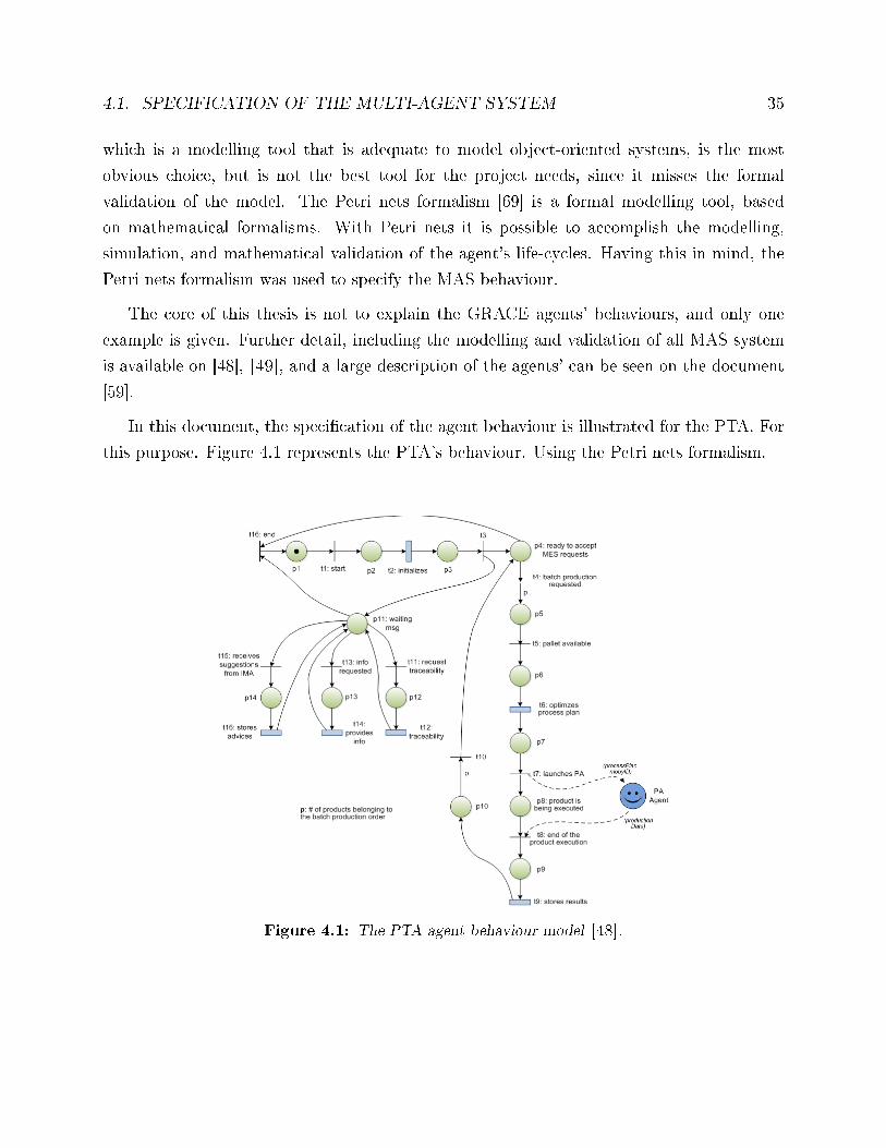
In this document, the speci�cation of the agent behaviour is illustrated for the PTA. For
this purpose. Figure 4.1 represents the PTA's behaviour. Using the Petri nets formalism.
Figure 4.1: The PTA agent behaviour model [48].
36CHAPTER 4. IMPLEMENTATIONOF THEGRACEMULTI-AGENT SYSTEM SOLUTION
Each Petri net model contains several timed transitions, which represents functions. As
example, in Figure 4.1, the transition t2 represents the functions related to the connection
to the database, starting the agent's GUI, and registration of the agent's skills that are on
the agent's pro�les. In a similar manner, the transition t6 represents the optimization of the
process plan. These transitions represent complex functions that can be exploded by a more
detailed sub-Petri nets model.
The PTA agent, after its initialization, enters in a state where it waits for a production
order to be executed. This order involves the execution of p products. Once the request
occurs, the PTA agent launches PA agents according to the availability of the pallets in the
production line. In the transition t7 the PTA agent interacts with other agents, namely the
PA.
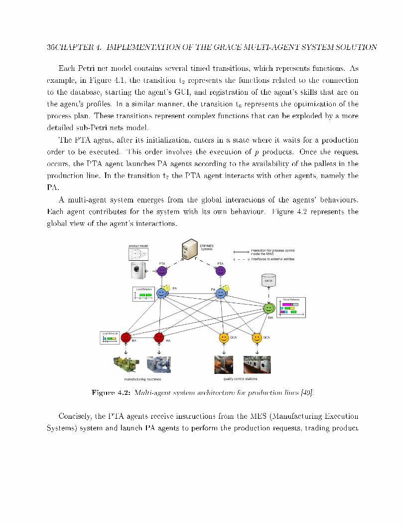
A multi-agent system emerges from the global interactions of the agents' behaviours.
Each agent contributes for the system with its own behaviour. Figure 4.2 represents the
global view of the agent's interactions.
Figure 4.2: Multi-agent system architecture for production lines [49].
Concisely, the PTA agents receive instructions from the MES (Manufacturing Execution
Systems) system and launch PA agents to perform the production requests, trading product
4.1. SPECIFICATION OF THE MULTI-AGENT SYSTEM 37
and process planning information. The PA agents cooperate with the RA agents during
the execution of the process plan. PA and RA agents interact with the IMA to provide
feedback information about the execution of the operations and the process plans and to
receive optimized guidelines to improve their execution, allowing the attainment of a global
modular, distributed, adaptive and recon�gurable control platform.
With the Petri nets formalism, the agents behaviour were formalized, but it is not possible
to represent the interactions among di�erent models. This means that it is necessary to model
the interactions with a diagram of interactions.
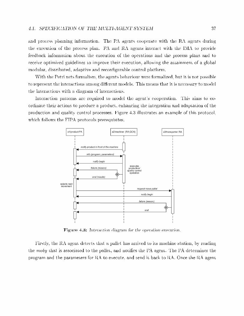
Interaction patterns are required to model the agent's cooperation. This aims to co-
ordinate their actions to produce a product, enhancing the integration and adaptation of the
production and quality control processes. Figure 4.3 illustrates an example of this protocol,
which follows the FIPA protocols prerequisites.
Figure 4.3: Interaction diagram for the operation execution.
Firstly, the RA agent detects that a pallet has arrived to its machine station, by reading
the moby that is associated to the pallet, and noti�es the PA agent. The PA determines the
program and the parameters for RA to execute, and send it back to RA. Once the RA agent
38CHAPTER 4. IMPLEMENTATIONOF THEGRACEMULTI-AGENT SYSTEM SOLUTION
�nishes the program execution, it sends another message to PA to inform the result of it,
which could be successful or failure. Reaching to this point, the PA agent check the process
plan for further operations and request a movement of the pallet to the next station to a
transport resource agent, which will deliver the pallet in the target station. All the GRACE
multi-agent system interactions are formalized in this mode.
4.2 Implementation of the Multi-agent System
There are several frameworks available for the implementation of agents based solutions.
These frameworks share the facility of the developers to abstract technical details and ad-
vance to the implementation of the agents' behaviours. The development of multi-agent
system solutions requires the implementation of features not supported by usual program-
ming languages, such as message transport, encoding and parsing, white and yellow pages
services, ontologies for common understanding and agent life-cycle management services.
This leads to an increase of productivity, reducing the implementation time for further detail
see appendix B.2.
After studying several tools, see appendix B.1 with a comparison analysis of several
frameworks, the JADE framework was selected. The main reasons for this are the fact of
being FIPA Compliant and having a Freeware license, with source code available on JADE
website.
JADE is a Java-based architecture that uses the Java Remote Method Invocation (RMI)
to support the creation of distributed Java technology-based to Java applications. Each agent
is implemented with Java �threads� and associated with a container.
Aiming to structure the implementation of the source code, a set of packages was created,
as illustrated in Figure 4.4 separating the concepts and functions associated to the MAS
application.
Each package contains a set of classes that executes the functionalities associated to the
agents. Some packages are related to only one agent, for example the PA package that is
only associated to the PA agent. As illustrated in Figure 4.5.
This PA package contains a set of classes, namely two for the agent (PA and WaitingMes-
sage class) and one related to the GUI (formPA class).
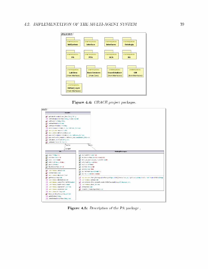
4.2. IMPLEMENTATION OF THE MULTI-AGENT SYSTEM 39
Figure 4.4: GRACE project packages.
Figure 4.5: Description of the PA package .
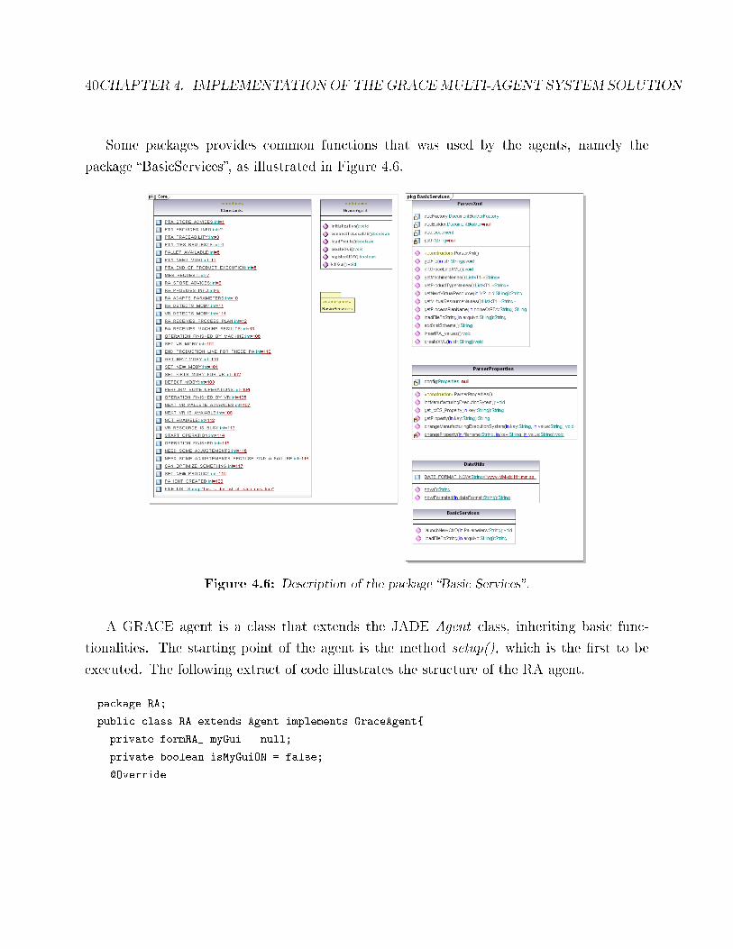
40CHAPTER 4. IMPLEMENTATIONOF THEGRACEMULTI-AGENT SYSTEM SOLUTION
Some packages provides common functions that was used by the agents, namely the
package �BasicServices�, as illustrated in Figure 4.6.
Figure 4.6: Description of the package �Basic Services�.
A GRACE agent is a class that extends the JADE Agent class, inheriting basic func-
tionalities. The starting point of the agent is the method setup(), which is the �rst to be
executed. The following extract of code illustrates the structure of the RA agent.
package RA;
public class RA extends Agent implements GraceAgent{
private formRA_ myGui = null;
private boolean isMyGuiON = false;
@Override
4.2. IMPLEMENTATION OF THE MULTI-AGENT SYSTEM 41
protected void setup(){
initialization();
// alocate the behaviour to handle the receive the messages
WaitingMessages waitingMessages = new WaitingMessages(this, isMyGuiON, myGui);
addBehaviour(waitingMessages);
}
...
}/* end of RA Class
The agent inherits basic functionalities, such as registration services, remote management
and send/receive ACL messages [7]. These functionalities were extended with features that
represent the speci�c behaviour of the agent, as described in [58]. Analysing the previous
piece of code it is possible to verify that in the beginning of the setup method, a initialization
function is executed being responsible to register the agents skills in the DF, connect to the
local database, and create a GUI component as illustrated in the following piece of code.
@Override
public void initialization(){
loadProfile();
registerAtDF();
connectToLocalDB();
createGui();
}
@Override
public boolean registerAtDF(){
boolean res = false;
DFAgentDescription dfd = new DFAgentDescription();
dfd.setName(getAID());
ServiceDescription service = new ServiceDescription();
service.setType("servico_RA");
service.setName(getLocalName());
dfd.addServices(service);
try {
DFService.register(this, dfd);
...
} ...
}
42CHAPTER 4. IMPLEMENTATIONOF THEGRACEMULTI-AGENT SYSTEM SOLUTION
The communication between distributed agents is done over the Ethernet network, using
TCP/IP protocol and is asynchronous, i.e. an agent that sends a message continues its
execution without the need to wait for the response. The messages speci�ed in the GRACE
multi-agent system are encoded using the FIPA-ACL communication language to achieve
normalized communication between the agents, being the content of the messages formatted
according to the FIPA-SL0 language. The meaning of the message content is standardized
according to the GRACE ontology.
For this purpose and since the behaviour of the agent is driven by the messages received
from the other agents (i.e. incoming events), a cyclic behaviour called WaitingMessages is
launched in the setup() method. This behaviour is a Java class that is waiting for the arrival
of messages, using the block() method to block the behaviour until a message arrives and the
receive() method to extract the incoming message, as illustrated in the next extract of code.
class WaitingMessages extends CyclicBehaviour implements IConstants, IConstants_GUI {
//atributes/*...*/
WaitingMessages(RA aThis, boolean myGuiON, formRA_ myGui){
myAgenteRA = aThis;
this.myGui = myGui;
this.isMyGuiON = myGuiON;
}
@Override
public void action(){
ACLMessage msg = myAgent.receive();
if (msg != null) {
Integer key = Integer.parseInt(msg.getConversationId());
switch (key) {
case RA_STORE_ADVICES:
myAgent.addBehaviour(new StoreAdvices()); //FuncRA_t13
break;
case RA_PROVIDES_INFO:
myAgent.addBehaviour(new ProvidesInfo()); //FunRA_t7
break;
case RA_ADAPTS_PARAMETERS:
adaptsParameters(); //Function RA_ t5
break;
4.2. IMPLEMENTATION OF THE MULTI-AGENT SYSTEM 43
case VR_DETECTS_MOBY:
System.out.println("[RA] RA recebeu o tick do VR");
}
}
else {
block();
}
} // end of WaitingMessages class
The arrival of a message triggers a set of actions related to decode the message and select
the proper actions to be performed. Looking to the code, if the message is not null, it is
veri�ed the conversation ID of the message, and depending of the conversation ID of the
message a di�erent behaviour or function is called. As an example, if the received message
has a ra_provides_info identi�cation, a new behaviour called ProvidesInfo() is triggered.
Note that after triggering the action related to the received message, the WaitingMessages
behaviour continues waiting for incoming messages continuously. All agents in the GRACE
system are able to receive messages following this approach. The behaviours launched in the
setup() method and those posteriorly invoked within these behaviours are also provided by
the resource agent package in the form of Java classes.
Besides all of these internal behaviours, a GRACE agent has connections with legacy
systems, e.g. with production database or quality control stations.
As example, the QCA may interact with LabView applications stored in the quality
control stations. The LabView application intends to perform quality control tests, but that
information should return to the agent.
For this purpose an interface linking the QCA and the LabView application was developed
using a sockets communication [52], which classes are aggregated in the LabView package
illustrated in Figure 4.7.
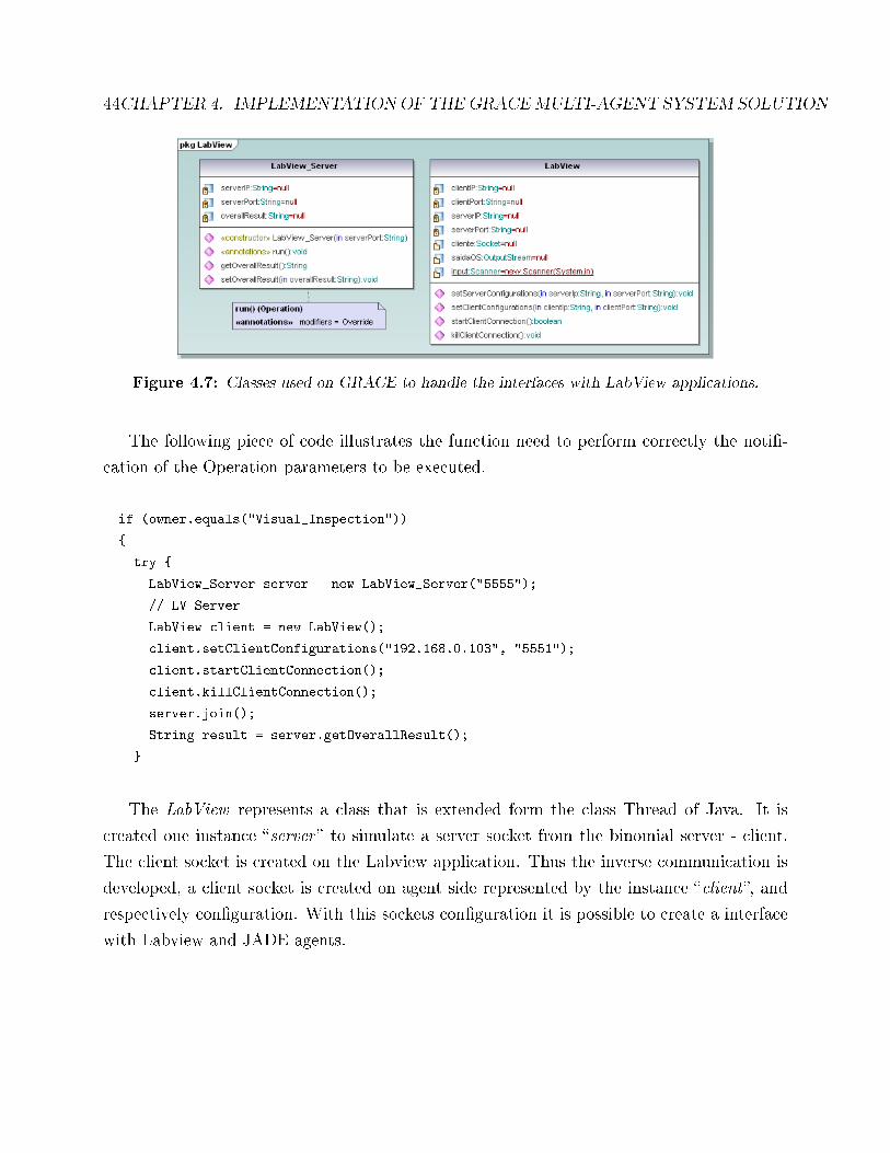
44CHAPTER 4. IMPLEMENTATIONOF THEGRACEMULTI-AGENT SYSTEM SOLUTION
Figure 4.7: Classes used on GRACE to handle the interfaces with LabView applications.
The following piece of code illustrates the function need to perform correctly the noti�-
cation of the Operation parameters to be executed.
if (owner.equals("Visual_Inspection"))
{
try {
LabView_Server server = new LabView_Server("5555");
// LV Server
LabView client = new LabView();
client.setClientConfigurations("192.168.0.103", "5551");
client.startClientConnection();
client.killClientConnection();
server.join();
String result = server.getOverallResult();
}
The LabView represents a class that is extended form the class Thread of Java. It is
created one instance �server � to simulate a server socket from the binomial server - client.
The client socket is created on the Labview application. Thus the inverse communication is
developed, a client socket is created on agent side represented by the instance �client�, and
respectively con�guration. With this sockets con�guration it is possible to create a interface
with Labview and JADE agents.
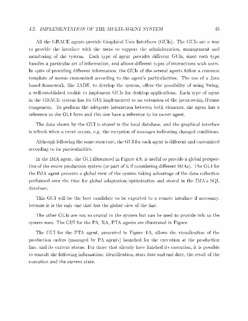
4.2. IMPLEMENTATION OF THE MULTI-AGENT SYSTEM 45
All the GRACE agents provide Graphical User Interfaces (GUIs). The GUIs are a way
to provide the interface with the users to support the administration, management and
monitoring of the system. Each type of agent provides di�erent GUIs, since each type
handles a particular set of information, and allows di�erent types of interactions with users.
In spite of providing di�erent information, the GUIs of the several agents follow a common
template of menus customized according to the agent's particularities. The use of a Java
based framework, like JADE, to develop the system, o�ers the possibility of using Swing,
a well-established toolkit to implement GUIs for desktop applications. Each type of agent
in the GRACE system has its GUI implemented as an extension of the javax.swing.JFrame
component. To perform the adequate interaction between both elements, the agent has a
reference to the GUI form and this one have a reference to its owner agent.
The data shown by the GUI is stored in the local database, and the graphical interface
is refresh when a event occurs, e.g. the reception of messages indicating changed conditions.
Although following the same structure, the GUI for each agent is di�erent and customized
according to its particularities.
In the IMA agent, the GUI illustrated in Figure 4.8, is useful to provide a global perspec-
tive of the entire production system (or part of it if considering di�erent IMAs). The GUI for
the IMA agent presents a global view of the system taking advantage of the data collection
performed over the time for global adaptation/optimization and stored in the IMA's SQL
database.
This GUI will be the best candidate to be exported to a remote interface if necessary,
because it is the only one that has the global view of the line.
The other GUIs are not so crucial in the system but can be used to provide info to the
system uses. The GUI for the PA, RA, PTA agents are illustrated in Figure.
The GUI for the PTA agent, presented in Figure 4.9, allows the visualization of the
production orders (managed by PA agents) launched for the execution at the production
line, and its current status. For those that already have �nished its execution, it is possible
to consult the following information: identi�cation, start date and end date, the result of the
execution and the current state.
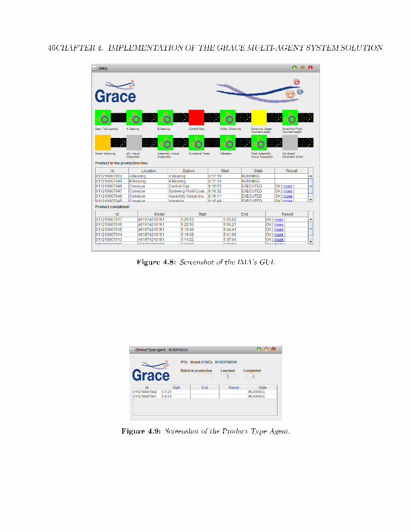
46CHAPTER 4. IMPLEMENTATIONOF THEGRACEMULTI-AGENT SYSTEM SOLUTION
Figure 4.8: Screenshot of the IMA's GUI.
Figure 4.9: Screenshot of the Product Type Agent.
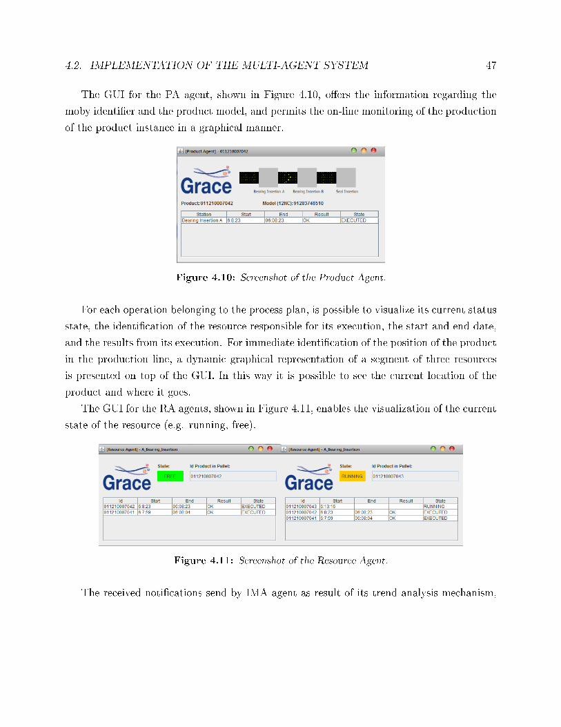
4.2. IMPLEMENTATION OF THE MULTI-AGENT SYSTEM 47
The GUI for the PA agent, shown in Figure 4.10, o�ers the information regarding the
moby identi�er and the product model, and permits the on-line monitoring of the production
of the product instance in a graphical manner.
Figure 4.10: Screenshot of the Product Agent.
For each operation belonging to the process plan, is possible to visualize its current status
state, the identi�cation of the resource responsible for its execution, the start and end date,
and the results from its execution. For immediate identi�cation of the position of the product
in the production line, a dynamic graphical representation of a segment of three resources
is presented on top of the GUI. In this way it is possible to see the current location of the
product and where it goes.
The GUI for the RA agents, shown in Figure 4.11, enables the visualization of the current
state of the resource (e.g. running, free).
Figure 4.11: Screenshot of the Resource Agent.
The received noti�cations send by IMA agent as result of its trend analysis mechanism,
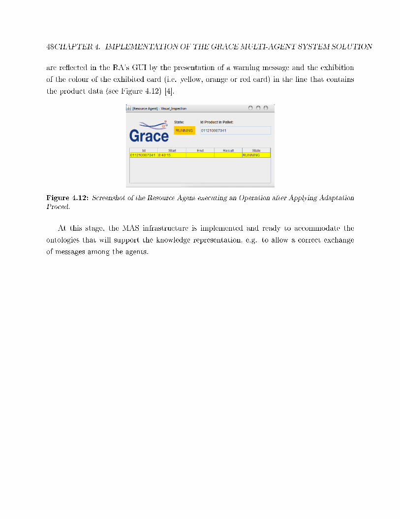
48CHAPTER 4. IMPLEMENTATIONOF THEGRACEMULTI-AGENT SYSTEM SOLUTION
are re�ected in the RA's GUI by the presentation of a warning message and the exhibition
of the colour of the exhibited card (i.e. yellow, orange or red card) in the line that contains
the product data (see Figure 4.12) [4].
Figure 4.12: Screenshot of the Resource Agent executing an Operation after Applying AdaptationProced.
At this stage, the MAS infrastructure is implemented and ready to accommodate the
ontologies that will support the knowledge representation, e.g. to allow a correct exchange
of messages among the agents.
Chapter 5
Design of the GRACE Ontology Schema
The implemented Multi-agent System, described in the previous chapter, is not completed if
a proper ontology is not used. This chapter describes the ontology design.
5.1 Introduction
The proposed GRACE ontology aims to represent the knowledge associated to the washing
machines production lines domain, which will be used in a multi-agent system application to
integrate the production and quality control processes. This ontology considers some insights
from PABADIS'PROMISE and ADACOR approaches as already mention before.
The ontology is founded on the de�nition of a taxonomy of manufacturing components,
which contributes to the formalisation and understanding of the problem. The ontology
schema de�nes the vocabulary terms used by distributed entities, the agents, and indicates
the concepts (objects or classes), the predicates (relation between the classes), the terms
(attributes of each class), and the meaning of each term (type of each attribute).
The design of an ontology passes by several steps, conceptualization, speci�cation, instan-
tiation, integration, evaluation and �nally documentation. Making a very brief explanation
and resuming only to three main phases, starting from the conceptualization of the ontology
where the speci�c domain is de�ned, and one starts to think in more general concepts and
specializing each one. Passing by the speci�cation of the ontology schema, this is based on
49
50 CHAPTER 5. DESIGN OF THE GRACE ONTOLOGY SCHEMA
the reunion of all these concepts, predicates and terms and then implemented on speci�c
ontological software, followed by the instantiation of the schema. For an easy understanding,
the GRACE ontology schema has been initially built using the UML class diagram format,
and posteriorly edited and instantiated in the Protégé framework using the OWL language.
For every ontology reuse or created from zero, it is mandatory that it has a purpose, at
least to have logic. It is important to be clear about the needs of the ontology.
The GRACE ontology aims to turn more interoperable the knowledge used by the multi-
agent system. As already mention the agents only have a partial view of the system.
For this purpose, GRACE ontology will provide the data structure to organize the knowl-
edge that is shared and exchanged between the agents and enable the interoperability between
them. In particular, the GRACE ontology formalizes the structure of the knowledge related
to:
• The resources available in the production line.
• Equipments available in the production line.
• The product and process models that describe how to produce the catalogue of products
in the production line.
• The description of the production history executed in the production line, including
the results from the inspection tests.
The GRACE ontology intends to formalize each concept, each process, and each object in
order to have all entities recognized, which lead to a better conceptualization and obviously
a good implementation, increasing quality control processes. During this process, the di�-
culty was referent to how and whether it be used the ontologies that already exist. Taking
in consideration that GRACE ontology is based on ADACOR and PABADIS'PROMISE, it
appears that question of. The solution was picking the best of these approaches and com-
ponents with new ones addressing the particularities of the domain. The global view of the
GRACE ontology can be seen in Figure 5.1.
In the Figure, it is represented all classes, relations, and attributes. The following sections
will detail more deeply each term.
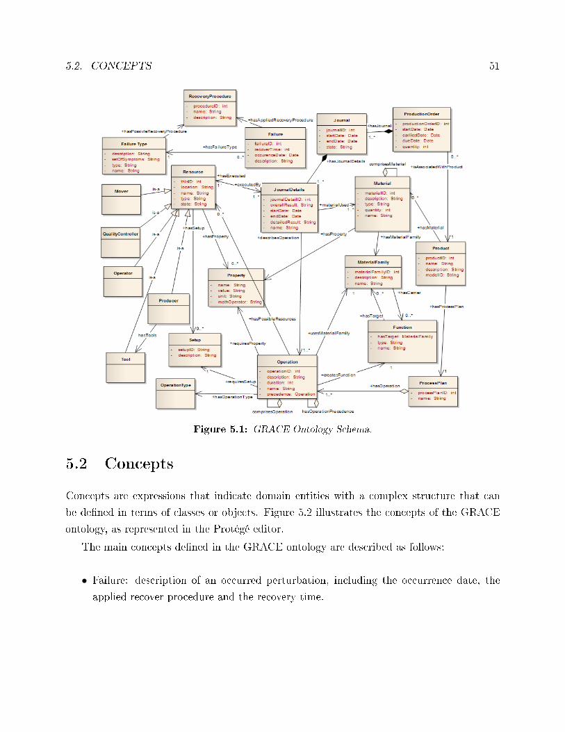
5.2. CONCEPTS 51
Figure 5.1: GRACE Ontology Schema.
5.2 Concepts
Concepts are expressions that indicate domain entities with a complex structure that can
be de�ned in terms of classes or objects. Figure 5.2 illustrates the concepts of the GRACE
ontology, as represented in the Protégé editor.
The main concepts de�ned in the GRACE ontology are described as follows:
• Failure: description of an occurred perturbation, including the occurrence date, the
applied recover procedure and the recovery time.
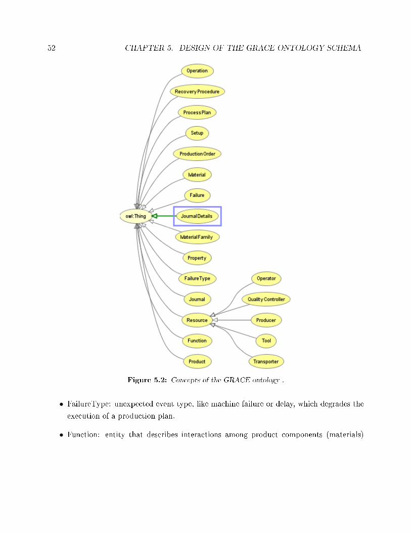
52 CHAPTER 5. DESIGN OF THE GRACE ONTOLOGY SCHEMA
Figure 5.2: Concepts of the GRACE ontology .
• FailureType: unexpected event type, like machine failure or delay, which degrades the
execution of a production plan.
• Function: entity that describes interactions among product components (materials)
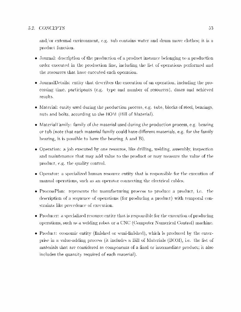
5.2. CONCEPTS 53
and/or external environment, e.g. tub contains water and drum move clothes; it is a
product function.
• Journal: description of the production of a product instance belonging to a production
order executed in the production line, including the list of operations performed and
the resources that have executed each operation.
• JournalDetails: entity that describes the execution of an operation, including the pro-
cessing time, participants (e.g. type and number of resources), dates and achieved
results.
• Material: entity used during the production process, e.g. tubs, blocks of steel, bearings,
nuts and bolts, according to the BOM (Bill of Material).
• MaterialFamily: family of the material used during the production process, e.g. bearing
or tub (note that each material family could have di�erent materials, e.g. for the family
bearing, it is possible to have the bearing A and B).
• Operation: a job executed by one resource, like drilling, welding, assembly, inspection
and maintenance that may add value to the product or may measure the value of the
product, e.g. the quality control.
• Operator: a specialized human resource entity that is responsible for the execution of
manual operations, such as an operator connecting the electrical cables.
• ProcessPlan: represents the manufacturing process to produce a product, i.e. the
description of a sequence of operations (for producing a product) with temporal con-
straints like precedence of execution.
• Producer: a specialized resource entity that is responsible for the execution of producing
operations, such as a welding robot or a CNC (Computer Numerical Control) machine.
• Product: economic entity (�nished or semi-�nished), which is produced by the enter-
prise in a value-adding process (it includes a Bill of Materials (BOM), i.e. the list of
materials that are considered as components of a �nal or intermediate product; it also
includes the quantity required of each material).
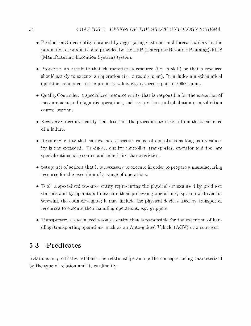
54 CHAPTER 5. DESIGN OF THE GRACE ONTOLOGY SCHEMA
• ProductionOrder: entity obtained by aggregating customer and forecast orders for the
production of products, and provided by the ERP (Enterprise Resource Planning)/MES
(Manufacturing Execution System) system.
• Property: an attribute that characterizes a resource (i.e. a skill) or that a resource
should satisfy to execute an operation (i.e. a requirement). It includes a mathematical
operator associated to the property value, e.g. a speed equal to 2000 r.p.m..
• QualityController: a specialized resource entity that is responsible for the execution of
measurement and diagnosis operations, such as a vision control station or a vibration
control station.
• RecoveryProcedure: entity that describes the procedure to recover from the occurrence
of a failure.
• Resource: entity that can execute a certain range of operations as long as its capac-
ity is not exceeded. Producer, quality controller, transporter, operator and tool are
specializations of resource and inherit its characteristics.
• Setup: set of actions that it is necessary to execute in order to prepare a manufacturing
resource for the execution of a range of operations.
• Tool: a specialized resource entity representing the physical devices used by producer
stations and by operators to execute their processing operations, e.g. screw driver for
screwing the counterweights; it may include the physical devices used by transporter
resources to execute their handling operations, e.g. grippers.
• Transporter: a specialized resource entity that is responsible for the execution of han-
dling/transporting operations, such as an Auto-guided Vehicle (AGV) or a conveyor.
5.3 Predicates
Relations or predicates establish the relationships among the concepts, being characterized
by the type of relation and its cardinality.
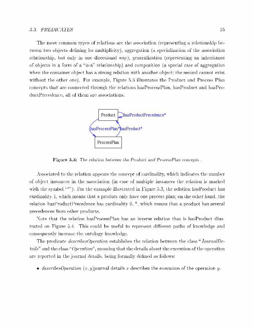
5.3. PREDICATES 55
The most common types of relations are the association (representing a relationship be-
tween two objects de�ning its multiplicity), aggregation (a specialization of the association
relationship, but only in one directional way), generalization (representing an inheritance
of objects in a form of a �is-a� relationship) and composition (a special case of aggregation
when the container object has a strong relation with another object; the second cannot exist
without the other one). For example, Figure 5.3 illustrates the Product and Process Plan
concepts that are connected through the relations hasProcessPlan, hasProduct and hasPro-
ductPrecedence, all of them are associations.
Figure 5.3: The relation between the Product and ProcessPlan concepts .
Associated to the relation appears the concept of cardinality, which indicates the number
of object instances in the association (in case of multiple instances the relation is marked
with the symbol �*�). For the example illustrated in Figure 5.3, the relation hasProduct has
cardinality 1, which means that a product only have one process plan; on the other hand, the
relation hasProductPrecedence has cardinality 0..*, which means that a product has several
precedences from other products.
Note that the relation hasProcessPlan has an inverse relation that is hasProduct illus-
trated on Figure 5.4. This could be useful to represent di�erent paths of knowledge and
consequently increase the ontology knowledge.
The predicate describesOperation establishes the relation between the class �JournalDe-
tails� and the class �Operation�, meaning that the details about the execution of the operation
are reported in the journal details, being formally de�ned as follows:
• describesOperation (x, y)journal details x describes the execution of the operation y.
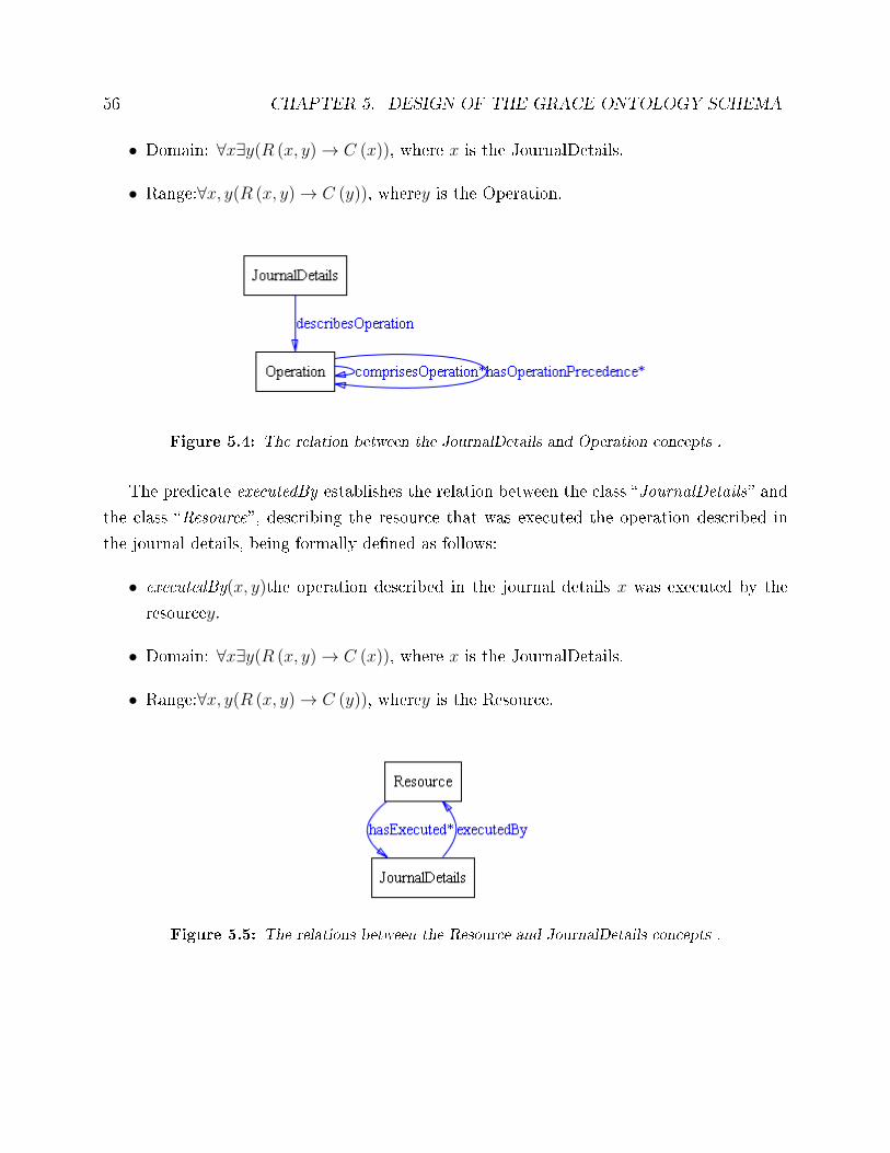
56 CHAPTER 5. DESIGN OF THE GRACE ONTOLOGY SCHEMA
• Domain: ∀x∃y(R (x, y)→ C (x)), where x is the JournalDetails.
• Range:∀x, y(R (x, y)→ C (y)), wherey is the Operation.
Figure 5.4: The relation between the JournalDetails and Operation concepts .
The predicate executedBy establishes the relation between the class �JournalDetails� and
the class �Resource�, describing the resource that was executed the operation described in
the journal details, being formally de�ned as follows:
• executedBy(x, y)the operation described in the journal details x was executed by the
resourcey.
• Domain: ∀x∃y(R (x, y)→ C (x)), where x is the JournalDetails.
• Range:∀x, y(R (x, y)→ C (y)), wherey is the Resource.
Figure 5.5: The relations between the Resource and JournalDetails concepts .
5.4. ATTRIBUTES 57
At this stage, the relations de�ned in the GRACE schema ontology are identi�ed and
described. Later on, in the section related to the restrictions, the description of the relations
will be completed by the de�nition of the type of relation (connection) and the cardinality
associated.
Due to the fact that the design of the ontology and its respective description are quite
extensive, the rest of the relations are described on the appendix A.1. Also a a design of the
predicates is represented on the appendix A.1.1.
5.4 Attributes
Attributes are values relative to properties of concepts. These values could be DataTypes
(e.g. string, integer) or PropertyTypes (i.e. ontology concepts, e.g. resource and operation,
established as relations). These attributes work like restrictions to the concepts (other types
of restrictions will be analysed in the next section).
The following Table 5.1 de�nes the main attributes established in the GRACE ontology.
In this de�nition, the item Domain refers to the concept that holds the attribute and the
item Range refers to the type of that attribute, e.g. �XSD.Integer� in case of Integer or
�XSD.string� in case of String.
From the analysis of the list of attributes, the concept Property requires a special atten-
tion. The tuple {name, value, unit, mathOperator}, associated to the datatype property,
represents the properties and characteristics exhibited by a resource or required by an oper-
ation to be performed. Examples of properties are:
• LifeTime: a positive rational number that de�nes the life time of a tool (expressed in
seconds).
• Axes: a non-negative integer, e.g. the number of axes of a machine.
• ProcessingType: a type of processing e.g. turning, milling, or drilling.
• Repeatability: a non-negative �oat, it gives an indication about the degree to which
repeated measurements under unchanged conditions show the same results (expressed
in mm).
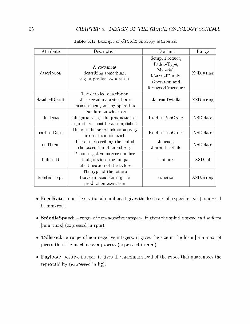
58 CHAPTER 5. DESIGN OF THE GRACE ONTOLOGY SCHEMA
Table 5.1: Example of GRACE ontology attributes.
Attribute Description Domain Range
description
A statement
describing something,
e.g. a product or a setup
Setup, Product,
FailureType,
Material,
MaterialFamily,
Operation and
RecoveryProcedure
XSD.string
detailedResult
The detailed description
of the results obtained in a
measurement/testing operation
JournalDetails XSD.string
dueDate
The date on which an
obligation, e.g. the production of
a product, must be accomplished
ProdutctionOrder XSD.date
earliestDateThe date before which an activity
or event cannot start.ProdutctionOrder XSD.date
endTimeThe date describing the end of
the execution of an activity
Journal,
Journal DetailsXSD.date
failureID
A non-negative integer number
that provides the unique
identi�cation of the failure
Failure XSD.int
functionType
The type of the failure
that can occur during the
production execution
Function XSD.string
• FeedRate: a positive rational number, it gives the feed rate of a speci�c axis (expressedin mm/rot).
• SpindleSpeed: a range of non-negative integers, it gives the spindle speed in the form
[min, max] (expressed in rpm).
• Tailstock: a range of non-negative integers, it gives the size in the form [min,max] of
pieces that the machine can process (expressed in mm).
• Payload: positive integer, it gives the maximum load of the robot that guarantees the
repeatability (expressed in kg).
5.5. RESTRICTIONS 59
• MaxReachability: positive integer, it gives the work volume of the robot (expressed
in mm).
• MagazineCapacity: non-negative integer, it gives the number of tools or grippers
that the magazine of a machine or robot can store.
• CuttingSpeed: a positive rational number, it gives the cutting speed (expressed in
mm/s).
• Wear: a positive number de�ning the wear of a cutting tool (expressed in mm).
• CycleTime: a positive number de�ning the length of the performed quality control
task (expressed in seconds).
• PercentOfScraps: a positive number de�ning the percentage of scraps identi�ed (re-
ferred to the total number of inspected items).
Due to the fact that the design of the ontology and its respective description are quite
extensive, the rest of the relations are on the appendix A.2.
5.5 Restrictions
The design of an ontology may consider the restrictions associated to the ontological con-
cepts, restricting the values and the cardinality associated to the identi�ed predicates. The
restrictions related to the values are created to implement the obligation of having the re-
lation among concepts, and the restrictions about the cardinality are related to create the
obligation in terms of number in those relations. Here, it is also important to consider the
restriction in the attributes associated to the allowed values.
This section de�nes the predicates restrictions, by directly mapping the UML classes into
the OWL concepts restrictions [39] see appendix A.3 for more details. In this description,
each concept is separately analysed and identi�ed the restrictions of the existing predicates
associated to the concept. The ful�lment of the identi�ed restrictions is crucial to preserve
the consistency of the ontology. It will be described only two examples of the restriction; the
rest is in the appendix A.3, thus making it easier to read.
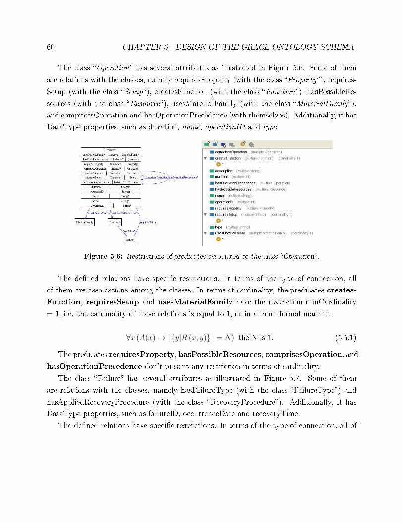
60 CHAPTER 5. DESIGN OF THE GRACE ONTOLOGY SCHEMA
The class �Operation� has several attributes as illustrated in Figure 5.6. Some of them
are relations with the classes, namely requiresProperty (with the class �Property�), requires-
Setup (with the class �Setup�), createsFunction (with the class �Function�), hasPossibleRe-
sources (with the class �Resource�), usesMaterialFamily (with the class �MaterialFamily�),
and comprisesOperation and hasOperationPrecedence (with themselves). Additionally, it has
DataType properties, such as duration, name, operationID and type.
Figure 5.6: Restrictions of predicates associated to the class �Operation�.
The de�ned relations have speci�c restrictions. In terms of the type of connection, all
of them are associations among the classes. In terms of cardinality, the predicates creates-
Function, requiresSetup and usesMaterialFamily have the restriction minCardinality
= 1, i.e. the cardinality of these relations is equal to 1, or in a more formal manner,
∀x (A(x)→ |{y|R (x, y)} | = N) the N is 1. (5.5.1)
The predicates requiresProperty, hasPossibleResources, comprisesOperation, and
hasOperationPrecedence don't present any restriction in terms of cardinality.
The class �Failure� has several attributes as illustrated in Figure 5.7. Some of them
are relations with the classes, namely hasFailureType (with the class �FailureType�) and
hasAppliedRecoveryProcedure (with the class �RecoveryProcedure�). Additionally, it has
DataType properties, such as failureID, occurrenceDate and recoveryTime.
The de�ned relations have speci�c restrictions. In terms of the type of connection, all of
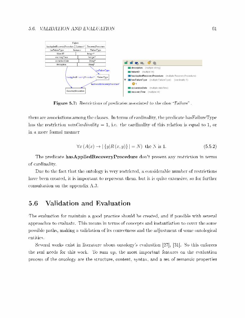
5.6. VALIDATION AND EVALUATION 61
Figure 5.7: Restrictions of predicates associated to the class �Failure� .
them are associations among the classes. In terms of cardinality, the predicate hasFailureType
has the restriction minCardinality = 1, i.e. the cardinality of this relation is equal to 1, or
in a more formal manner
∀x (A(x)→ |{y|R (x, y)} | = N) the N is 1. (5.5.2)
The predicate hasAppliedRecoveryProcedure don't present any restriction in terms
of cardinality.
Due to the fact that the ontology is very restricted, a considerable number of restrictions
have been created, it is important to represent them, but it is quite extensive, so for further
consultation on the appendix A.3.
5.6 Validation and Evaluation
The evaluation for maintain a good practice should be created, and if possible with several
approaches to evaluate. This means in terms of concepts and instantiation to cover the some
possible paths, making a validation of its correctness and the adjustment of some ontological
entities.
Several works exist in literature about ontology's evaluation [27], [31]. So this enforces
the real needs for this work. To sum up, the most important features on the evaluation
process of the ontology are the structure, content, syntax, and a set of semantic properties
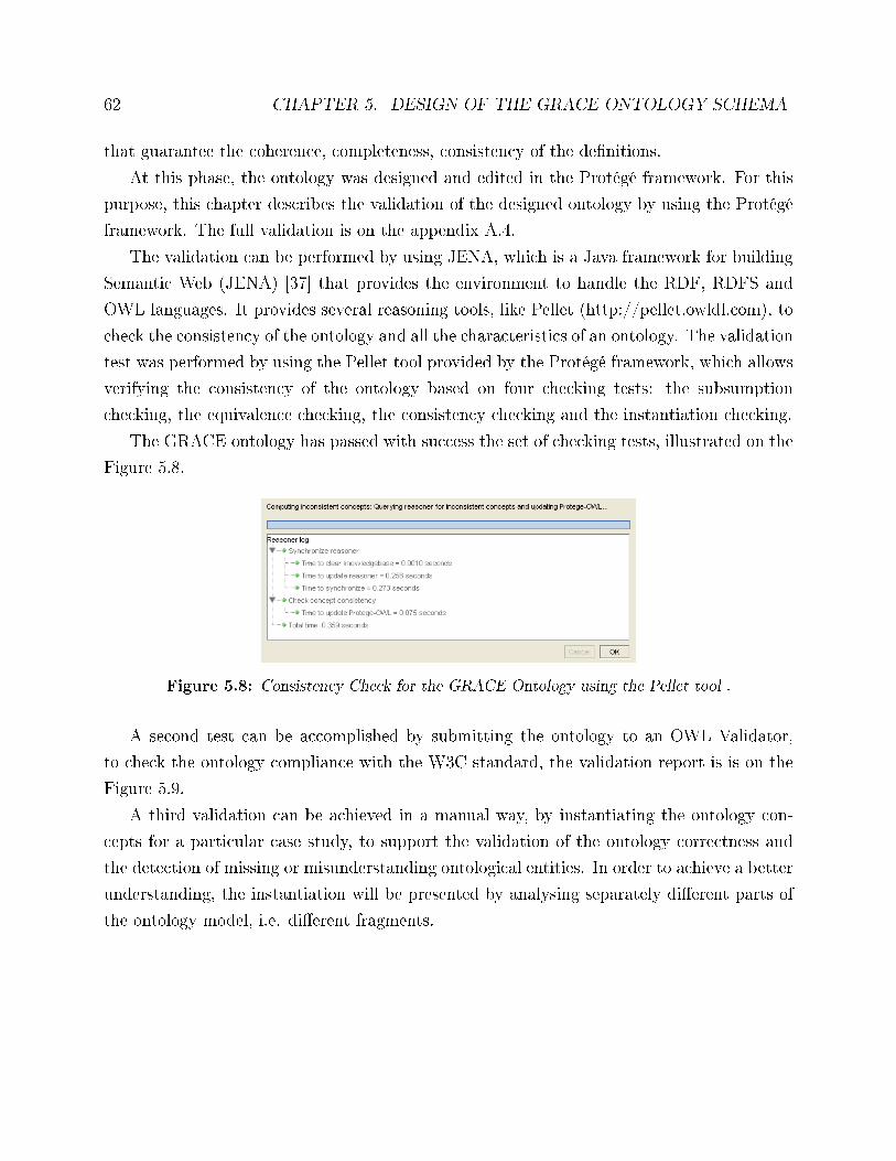
62 CHAPTER 5. DESIGN OF THE GRACE ONTOLOGY SCHEMA
that guarantee the coherence, completeness, consistency of the de�nitions.
At this phase, the ontology was designed and edited in the Protégé framework. For this
purpose, this chapter describes the validation of the designed ontology by using the Protégé
framework. The full validation is on the appendix A.4.
The validation can be performed by using JENA, which is a Java framework for building
Semantic Web (JENA) [37] that provides the environment to handle the RDF, RDFS and
OWL languages. It provides several reasoning tools, like Pellet (http://pellet.owldl.com), to
check the consistency of the ontology and all the characteristics of an ontology. The validation
test was performed by using the Pellet tool provided by the Protégé framework, which allows
verifying the consistency of the ontology based on four checking tests: the subsumption
checking, the equivalence checking, the consistency checking and the instantiation checking.
The GRACE ontology has passed with success the set of checking tests, illustrated on the
Figure 5.8.
Figure 5.8: Consistency Check for the GRACE Ontology using the Pellet tool .
A second test can be accomplished by submitting the ontology to an OWL Validator,
to check the ontology compliance with the W3C standard, the validation report is is on the
Figure 5.9.
A third validation can be achieved in a manual way, by instantiating the ontology con-
cepts for a particular case study, to support the validation of the ontology correctness and
the detection of missing or misunderstanding ontological entities. In order to achieve a better
understanding, the instantiation will be presented by analysing separately di�erent parts of
the ontology model, i.e. di�erent fragments.
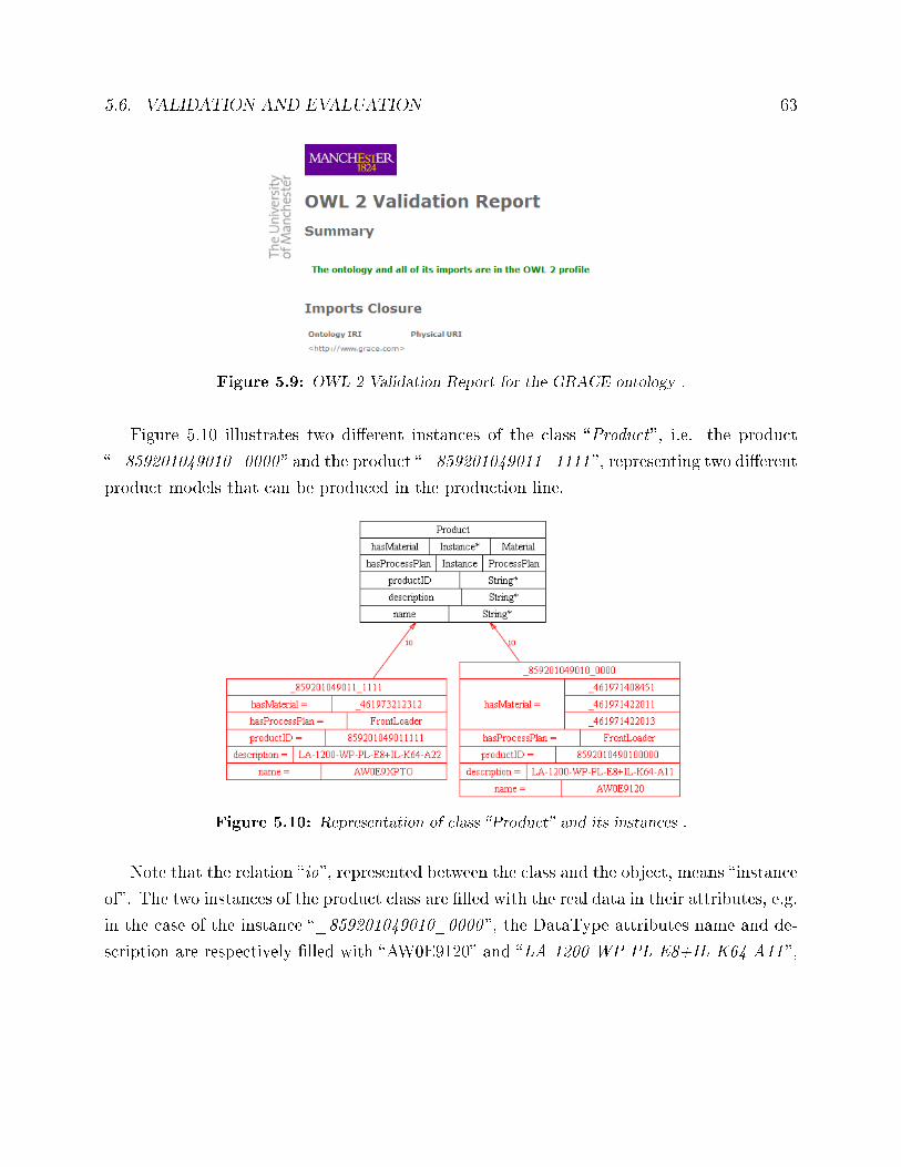
5.6. VALIDATION AND EVALUATION 63
Figure 5.9: OWL 2 Validation Report for the GRACE ontology .
Figure 5.10 illustrates two di�erent instances of the class �Product�, i.e. the product
�_859201049010_0000 � and the product �_859201049011_1111 �, representing two di�erent
product models that can be produced in the production line.
Figure 5.10: Representation of class �Product� and its instances .
Note that the relation �io�, represented between the class and the object, means �instance
of�. The two instances of the product class are �lled with the real data in their attributes, e.g.
in the case of the instance �_859201049010_0000 �, the DataType attributes name and de-
scription are respectively �lled with �AW0E9120� and �LA-1200-WP-PL-E8+IL-K64-A11 �,
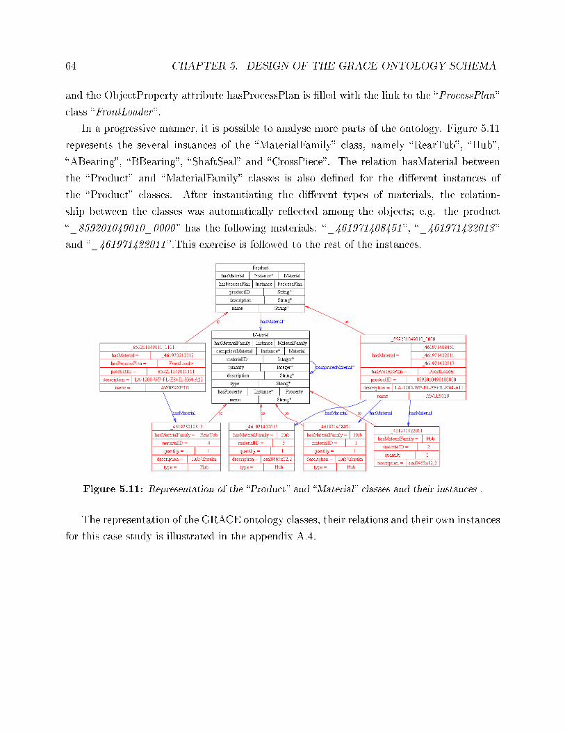
64 CHAPTER 5. DESIGN OF THE GRACE ONTOLOGY SCHEMA
and the ObjectProperty attribute hasProcessPlan is �lled with the link to the �ProcessPlan�
class �FrontLoader �.
In a progressive manner, it is possible to analyse more parts of the ontology. Figure 5.11
represents the several instances of the �MaterialFamily� class, namely �RearTub�, �Hub�,
�ABearing�, �BBearing�, �ShaftSeal� and �CrossPiece�. The relation hasMaterial between
the �Product� and �MaterialFamily� classes is also de�ned for the di�erent instances of
the �Product� classes. After instantiating the di�erent types of materials, the relation-
ship between the classes was automatically re�ected among the objects; e.g. the product
�_859201049010_0000 � has the following materials: �_461971408451 �, �_461971422013 �
and �_461971422011 �.This exercise is followed to the rest of the instances.
Figure 5.11: Representation of the �Product� and �Material� classes and their instances .
The representation of the GRACE ontology classes, their relations and their own instances
for this case study is illustrated in the appendix A.4.
Chapter 6
Integration of the Ontology in the
GRACE Multi-agent System
The ontology designed plays a crucial role in the GRACE MAS to enable a common under-
standing among the agents when they are communicating, namely to understand the message
at the syntactic level (to extract the content correctly) and at the semantic level (to acquire
the exchanged knowledge). This chapter describes the integration of the designed ontology
in the developed multi-agent system solution.
6.1 Available Solutions
Since the GRACE multi-agent system is being developed using the JADE, which uses Java,
a pertinent question is how to translate the ontology edited and validated in Protégé during
the Chapter 5 to be used by the agents developed in JADE. Several options can be considered
for this purpose.
The exchange of messages with ontologies structure in JADE normally uses an internal
container with a restrict format. Due to the fact that the messages are FIPA compliance,
JADE agents are able to interact with other agents, not only from the JADE platform but
with di�erent systems. For this purpose, JADE created a reference model along with some
notions: Concept, Agent Action and Predicate.
65
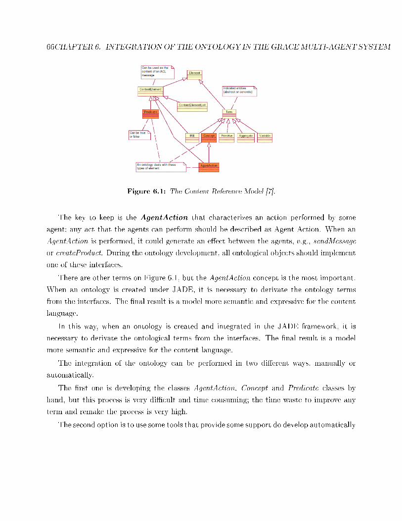
66CHAPTER 6. INTEGRATION OF THE ONTOLOGY IN THEGRACEMULTI-AGENT SYSTEM
Figure 6.1: The Content Reference Model [7].
The key to keep is the AgentAction that characterizes an action performed by some
agent; any act that the agents can perform should be described as Agent Action. When an
AgentAction is performed, it could generate an e�ect between the agents, e.g., sendMessage
or createProduct. During the ontology development, all ontological objects should implement
one of these interfaces.
There are other terms on Figure 6.1, but the AgentAction concept is the most important.
When an ontology is created under JADE, it is necessary to derivate the ontology terms
from the interfaces. The �nal result is a model more semantic and expressive for the content
language.
In this way, when an ontology is created and integrated in the JADE framework, it is
necessary to derivate the ontological terms from the interfaces. The �nal result is a model
more semantic and expressive for the content language.
The integration of the ontology can be performed in two di�erent ways, manually or
automatically.
The �rst one is developing the classes AgentAction, Concept and Predicate classes by
hand, but this process is very di�cult and time consuming; the time waste to improve any
term and remake the process is very high.
The second option is to use some tools that provide some support do develop automatically
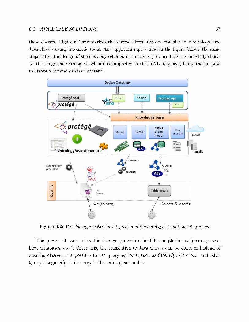
6.1. AVAILABLE SOLUTIONS 67
these classes. Figure 6.2 summarizes the several alternatives to translate the ontology into
Java classes using automatic tools. Any approach represented in the �gure follows the same
steps: after the design of the ontology schema, it is necessary to produce the knowledge base.
At this stage the ontological schema is supported in the OWL language, being the purpose
to create a common shared content.
Figure 6.2: Possible approaches for integration of the ontology in multi-agent systems.
The presented tools allow the storage procedure in di�erent platforms (memory, text
�les, databases, etc.). After this, the translation to Java classes can be done, or instead of
creating classes, it is possible to use querying tools, such as SPARQL (Protocol and RDF
Query Language), to interrogate the ontological model.
68CHAPTER 6. INTEGRATION OF THE ONTOLOGY IN THEGRACEMULTI-AGENT SYSTEM
One possible approach is to implement the ontology tool in Java through Jena frame-
work. After de�ning the classes, predicates and constraints it is possible to export to OWL
format, and save in several formats locally or remotely on a database. The multi-agent
system solution, must use that classes initially created, thus it is necessary to convert the
OWL �le into Java classes, also the properties in the owl �le has a direct relation with the
attributes of the classes in Java. This last step can be automated if it is used the plug-in
OntologyBeanGenerator.
There are several tools to perform automatically the implementation of the knowledge,
in this work it is only intended to choose one that best �ts the needs and constraints of the
scope of this project. It is important to use a tool that facilitates a fast development, in that
way a restriction of an interface is important. The exporting process is another important
limitation, because if agents cannot use this information, it becomes useless. Figure 6.3 sum-
marizes the comparison of the several tools regarding some aspects to have in consideration
when choosing the best tool.
The selection of the alternative that best �ts the needs and constraints of this project,
must consider issues like the facility to have a fast development and the exporting pro-
cess. The referred alternatives allow reasoning and data importation from several kinds of
databases and also reasoning
Jena is a common framework that can be used in several approaches. It can be used
individually, but it is explicitly used as the basis of Protégé API. Moreover, it was building
a plug-in for JADE to use OWL �les. This plugin, entitled AgentOWL [43], is available
on the website of JADE, and uses pure OWL �les. Analysing the �gure the one that best
�ts the requirements of this project is the Protégé Bean Generator + Protégé (second case).
The Protégé o�ers an export to di�erent formats (RDF, OWL, etc.), by adding the Protégé
plugin an exportation to Java classes is o�ered.
However, this approach has some disadvantages, namely the loss of �exibility in multi-
agent systems, because this approach loses the rationalization of new facts and new rules that
will have to be in the ontology, with advanced methods, such as Java Re�exion or Jess (rule
engine for the Java platform). If an approach that works with OWL is chosen, the tool can
run an inference engine with a set of rules, for example expressed in SWRL (Semantic Web
Rule Language) and SPARQL (with inserts). But for this work, this kind of transformation
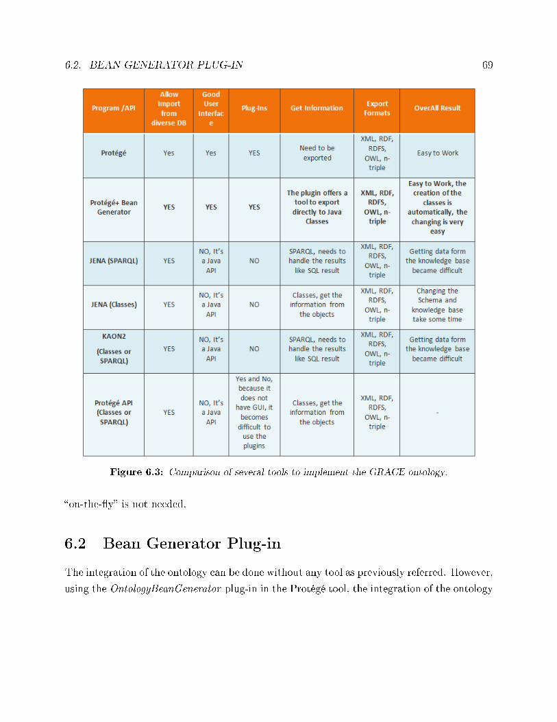
6.2. BEAN GENERATOR PLUG-IN 69
Figure 6.3: Comparison of several tools to implement the GRACE ontology.
�on-the-�y� is not needed.
6.2 Bean Generator Plug-in
The integration of the ontology can be done without any tool as previously referred. However,
using the OntologyBeanGenerator plug-in in the Protégé tool, the integration of the ontology
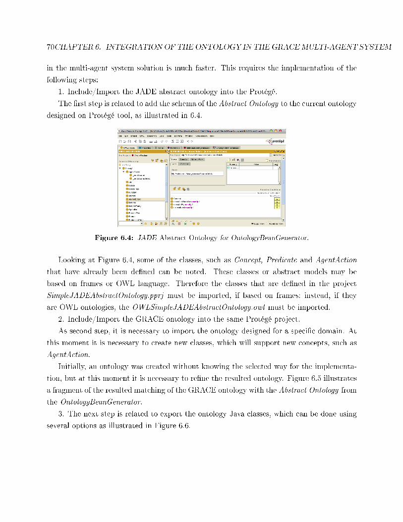
70CHAPTER 6. INTEGRATION OF THE ONTOLOGY IN THEGRACEMULTI-AGENT SYSTEM
in the multi-agent system solution is much faster. This requires the implementation of the
following steps:
1. Include/Import the JADE abstract ontology into the Protégé.
The �rst step is related to add the schema of the Abstract Ontology to the current ontology
designed on Protégé tool, as illustrated in 6.4.
Figure 6.4: JADE Abstract Ontology for OntologyBeanGenerator.
Looking at Figure 6.4, some of the classes, such as Concept, Predicate and AgentAction
that have already been de�ned can be noted. These classes or abstract models may be
based on frames or OWL language. Therefore the classes that are de�ned in the project
SimpleJADEAbstractOntology.pprj must be imported, if based on frames; instead, if they
are OWL ontologies, the OWLSimpleJADEAbstractOntology.owl must be imported.
2. Include/Import the GRACE ontology into the same Protégé project.
As second step, it is necessary to import the ontology designed for a speci�c domain. At
this moment it is necessary to create new classes, which will support new concepts, such as
AgentAction.
Initially, an ontology was created without knowing the selected way for the implementa-
tion, but at this moment it is necessary to re�ne the resulted ontology. Figure 6.5 illustrates
a fragment of the resulted matching of the GRACE ontology with the Abstract Ontology from
the OntologyBeanGenerator.
3. The next step is related to export the ontology Java classes, which can be done using
several options as illustrated in Figure 6.6.
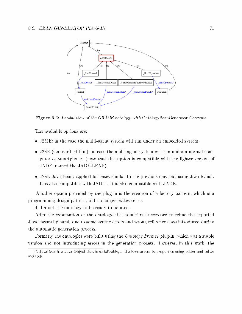
6.2. BEAN GENERATOR PLUG-IN 71
Figure 6.5: Partial view of the GRACE ontology with OntologyBeanGenerator Concepts
The available options are:
• J2ME: in the case the multi-agent system will run under an embedded system.
• J2SE (standard edition): in case the multi-agent system will run under a normal com-
puter or smartphones (note that this option is compatible with the lighter version of
JADE, named the JADE-LEAP).
• J2SE Java Bean: applied for cases similar to the previous one, but using JavaBeans1.
It is also compatible with JADE.. It is also compatible with JADE.
Another option provided by the plug-in is the creation of a factory pattern, which is a
programming design pattern, but no longer makes sense.
4. Import the ontology to be ready to be used.
After the exportation of the ontology, it is sometimes necessary to re�ne the exported
Java classes by hand, due to some syntax errors and wrong reference class introduced during
the automatic generation process.
Formerly the ontologies were built using the Ontology Frames plug-in, which was a stable
version and not introducing errors in the generation process. However, in this work, the
1A JavaBean is a Java Object that is serializable, and allows access to properties using getter and settermethods
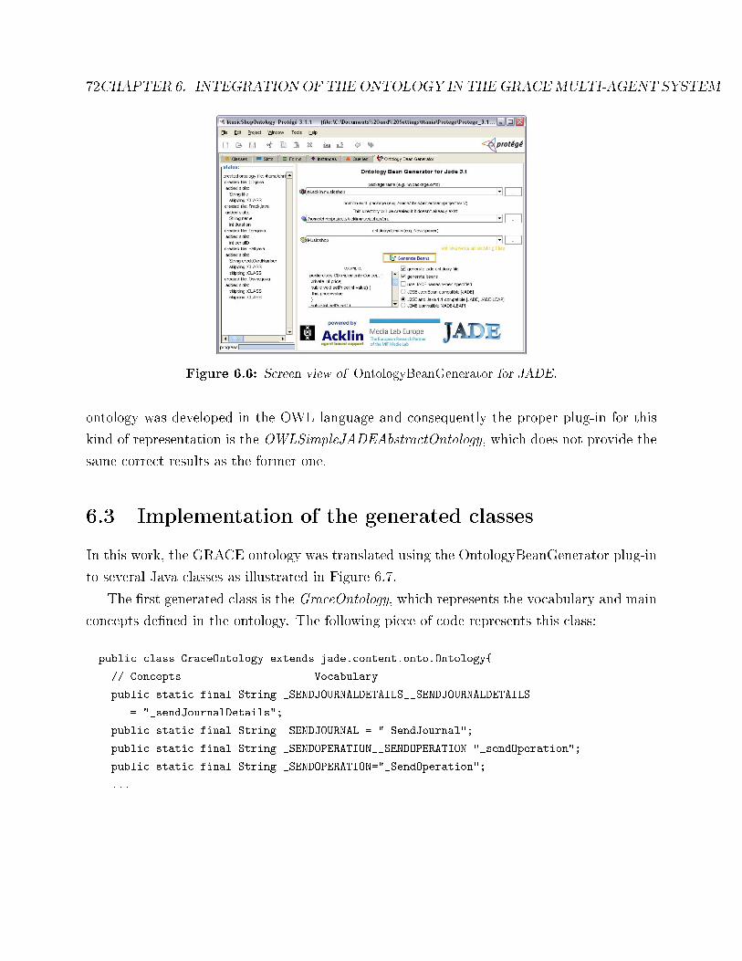
72CHAPTER 6. INTEGRATION OF THE ONTOLOGY IN THEGRACEMULTI-AGENT SYSTEM
Figure 6.6: Screen view of OntologyBeanGenerator for JADE.
ontology was developed in the OWL language and consequently the proper plug-in for this
kind of representation is the OWLSimpleJADEAbstractOntology, which does not provide the
same correct results as the former one.
6.3 Implementation of the generated classes
In this work, the GRACE ontology was translated using the OntologyBeanGenerator plug-in
to several Java classes as illustrated in Figure 6.7.
The �rst generated class is the GraceOntology, which represents the vocabulary and main
concepts de�ned in the ontology. The following piece of code represents this class:
public class GraceOntology extends jade.content.onto.Ontology{
// Concepts =================== Vocabulary ===========================
public static final String _SENDJOURNALDETAILS__SENDJOURNALDETAILS
= "_sendJournalDetails";
public static final String _SENDJOURNAL = "_SendJournal";
public static final String _SENDOPERATION__SENDOPERATION="_sendOperation";
public static final String _SENDOPERATION="_SendOperation";
...
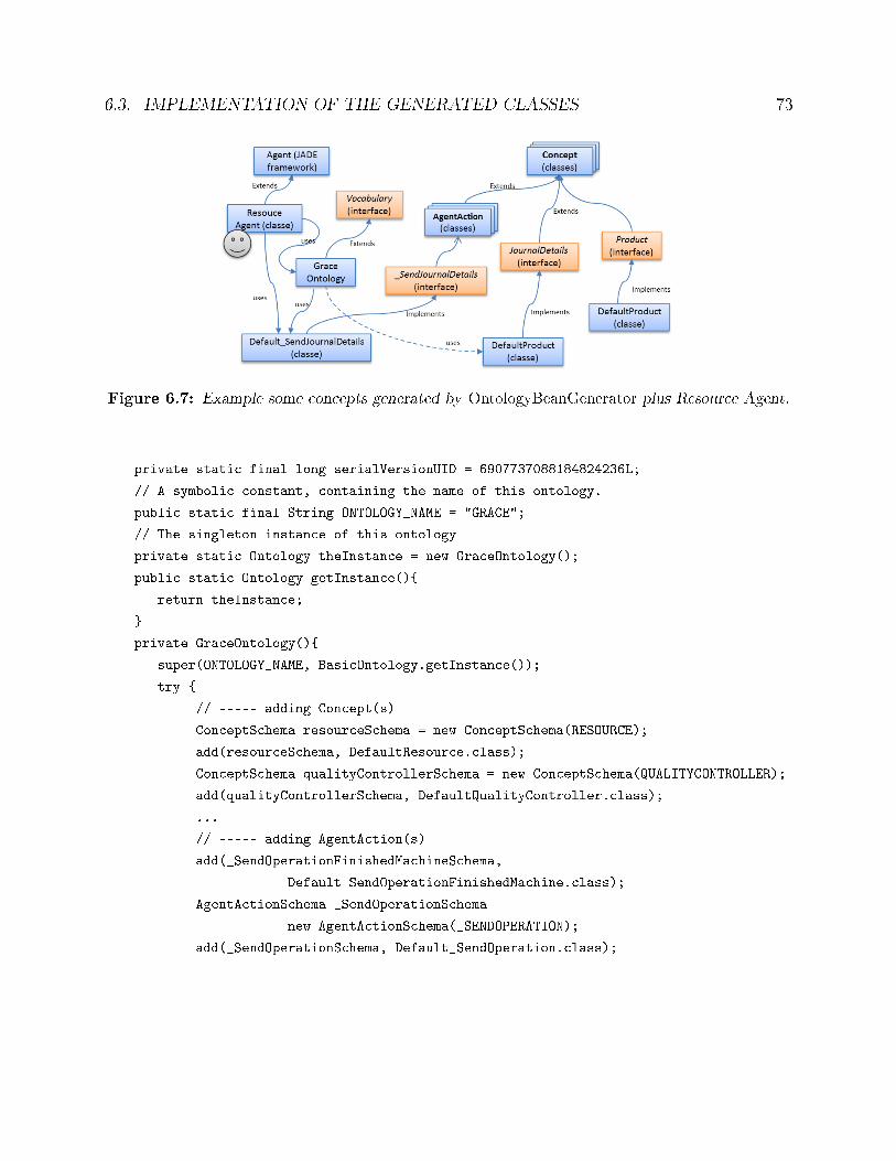
6.3. IMPLEMENTATION OF THE GENERATED CLASSES 73
Figure 6.7: Example some concepts generated by OntologyBeanGenerator plus Resource Agent.
private static final long serialVersionUID = 6907737088184824236L;
// A symbolic constant, containing the name of this ontology.
public static final String ONTOLOGY_NAME = "GRACE";
// The singleton instance of this ontology
private static Ontology theInstance = new GraceOntology();
public static Ontology getInstance(){
return theInstance;
}
private GraceOntology(){
super(ONTOLOGY_NAME, BasicOntology.getInstance());
try {
// ----- adding Concept(s)
ConceptSchema resourceSchema = new ConceptSchema(RESOURCE);
add(resourceSchema, DefaultResource.class);
ConceptSchema qualityControllerSchema = new ConceptSchema(QUALITYCONTROLLER);
add(qualityControllerSchema, DefaultQualityController.class);
...
// ----- adding AgentAction(s)
add(_SendOperationFinishedMachineSchema,
Default_SendOperationFinishedMachine.class);
AgentActionSchema _SendOperationSchema =
new AgentActionSchema(_SENDOPERATION);
add(_SendOperationSchema, Default_SendOperation.class);
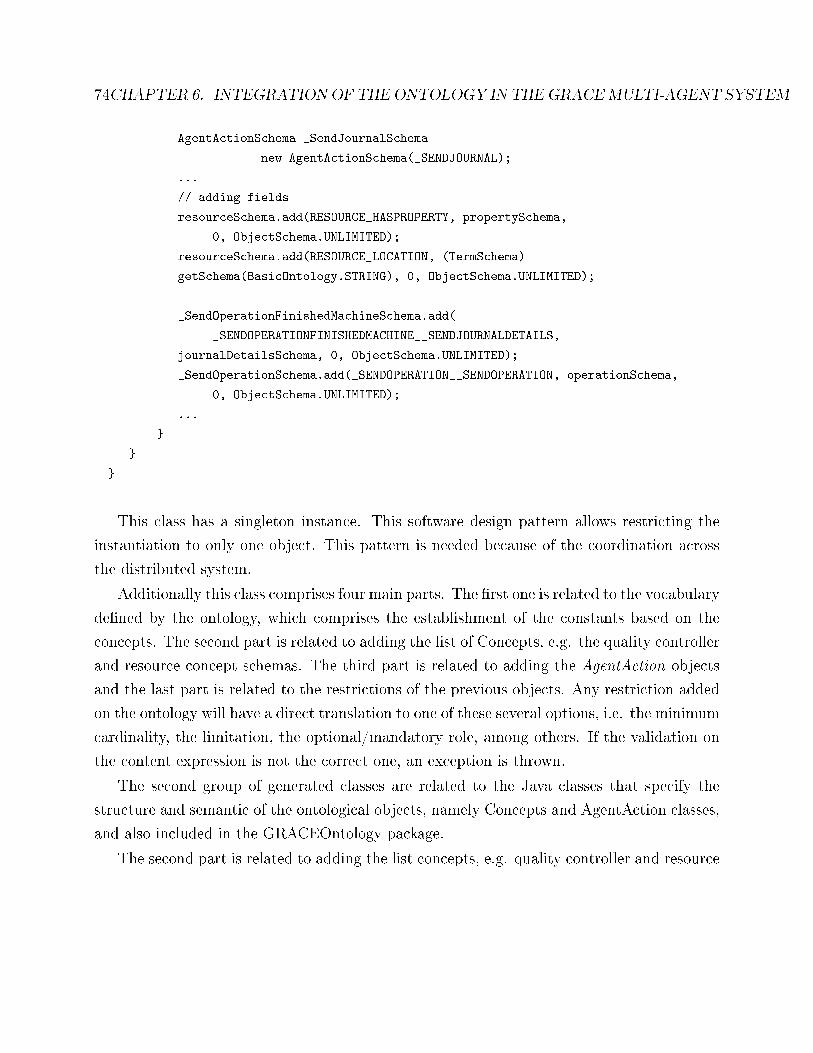
74CHAPTER 6. INTEGRATION OF THE ONTOLOGY IN THEGRACEMULTI-AGENT SYSTEM
AgentActionSchema _SendJournalSchema =
new AgentActionSchema(_SENDJOURNAL);
...
// adding fields
resourceSchema.add(RESOURCE_HASPROPERTY, propertySchema,
0, ObjectSchema.UNLIMITED);
resourceSchema.add(RESOURCE_LOCATION, (TermSchema)
getSchema(BasicOntology.STRING), 0, ObjectSchema.UNLIMITED);
_SendOperationFinishedMachineSchema.add(
_SENDOPERATIONFINISHEDMACHINE__SENDJOURNALDETAILS,
journalDetailsSchema, 0, ObjectSchema.UNLIMITED);
_SendOperationSchema.add(_SENDOPERATION__SENDOPERATION, operationSchema,
0, ObjectSchema.UNLIMITED);
...
}
}
}
This class has a singleton instance. This software design pattern allows restricting the
instantiation to only one object. This pattern is needed because of the coordination across
the distributed system.
Additionally this class comprises four main parts. The �rst one is related to the vocabulary
de�ned by the ontology, which comprises the establishment of the constants based on the
concepts. The second part is related to adding the list of Concepts, e.g. the quality controller
and resource concept schemas. The third part is related to adding the AgentAction objects
and the last part is related to the restrictions of the previous objects. Any restriction added
on the ontology will have a direct translation to one of these several options, i.e. the minimum
cardinality, the limitation, the optional/mandatory role, among others. If the validation on
the content expression is not the correct one, an exception is thrown.
The second group of generated classes are related to the Java classes that specify the
structure and semantic of the ontological objects, namely Concepts and AgentAction classes,
and also included in the GRACEOntology package.
The second part is related to adding the list concepts, e.g. quality controller and resource
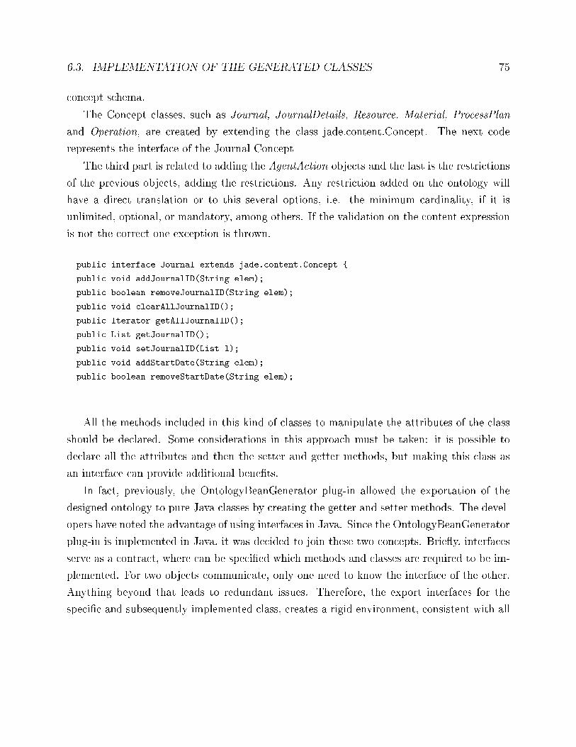
6.3. IMPLEMENTATION OF THE GENERATED CLASSES 75
concept schema.
The Concept classes, such as Journal, JournalDetails, Resource, Material, ProcessPlan
and Operation, are created by extending the class jade.content.Concept. The next code
represents the interface of the Journal Concept
The third part is related to adding the AgentAction objects and the last is the restrictions
of the previous objects, adding the restrictions. Any restriction added on the ontology will
have a direct translation or to this several options, i.e. the minimum cardinality, if it is
unlimited, optional, or mandatory, among others. If the validation on the content expression
is not the correct one exception is thrown.
public interface Journal extends jade.content.Concept {
public void addJournalID(String elem);
public boolean removeJournalID(String elem);
public void clearAllJournalID();
public Iterator getAllJournalID();
public List getJournalID();
public void setJournalID(List l);
public void addStartDate(String elem);
public boolean removeStartDate(String elem);
All the methods included in this kind of classes to manipulate the attributes of the class
should be declared. Some considerations in this approach must be taken: it is possible to
declare all the attributes and then the setter and getter methods, but making this class as
an interface can provide additional bene�ts.
In fact, previously, the OntologyBeanGenerator plug-in allowed the exportation of the
designed ontology to pure Java classes by creating the getter and setter methods. The devel-
opers have noted the advantage of using interfaces in Java. Since the OntologyBeanGenerator
plug-in is implemented in Java, it was decided to join these two concepts. Brie�y, interfaces
serve as a contract, where can be speci�ed which methods and classes are required to be im-
plemented. For two objects communicate, only one need to know the interface of the other.
Anything beyond that leads to redundant issues. Therefore, the export interfaces for the
speci�c and subsequently implemented class, creates a rigid environment, consistent with all
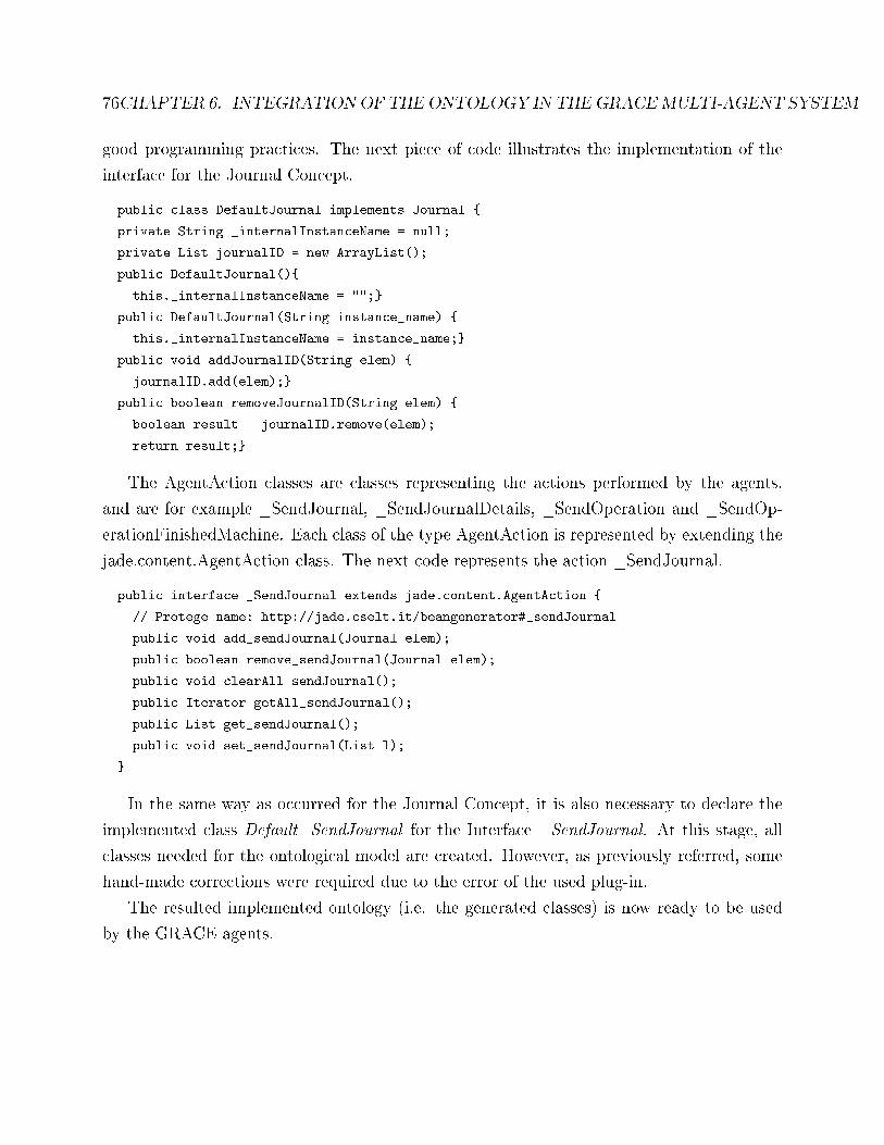
76CHAPTER 6. INTEGRATION OF THE ONTOLOGY IN THEGRACEMULTI-AGENT SYSTEM
good programming practices. The next piece of code illustrates the implementation of the
interface for the Journal Concept.
public class DefaultJournal implements Journal {
private String _internalInstanceName = null;
private List journalID = new ArrayList();
public DefaultJournal(){
this._internalInstanceName = "";}
public DefaultJournal(String instance_name) {
this._internalInstanceName = instance_name;}
public void addJournalID(String elem) {
journalID.add(elem);}
public boolean removeJournalID(String elem) {
boolean result = journalID.remove(elem);
return result;}
The AgentAction classes are classes representing the actions performed by the agents,
and are for example _SendJournal, _SendJournalDetails, _SendOperation and _SendOp-
erationFinishedMachine. Each class of the type AgentAction is represented by extending the
jade.content.AgentAction class. The next code represents the action _SendJournal.
public interface _SendJournal extends jade.content.AgentAction {
// Protege name: http://jade.cselt.it/beangenerator#_sendJournal
public void add_sendJournal(Journal elem);
public boolean remove_sendJournal(Journal elem);
public void clearAll_sendJournal();
public Iterator getAll_sendJournal();
public List get_sendJournal();
public void set_sendJournal(List l);
}
In the same way as occurred for the Journal Concept, it is also necessary to declare the
implemented class Default_SendJournal for the Interface _SendJournal. At this stage, all
classes needed for the ontological model are created. However, as previously referred, some
hand-made corrections were required due to the error of the used plug-in.
The resulted implemented ontology (i.e. the generated classes) is now ready to be used
by the GRACE agents.
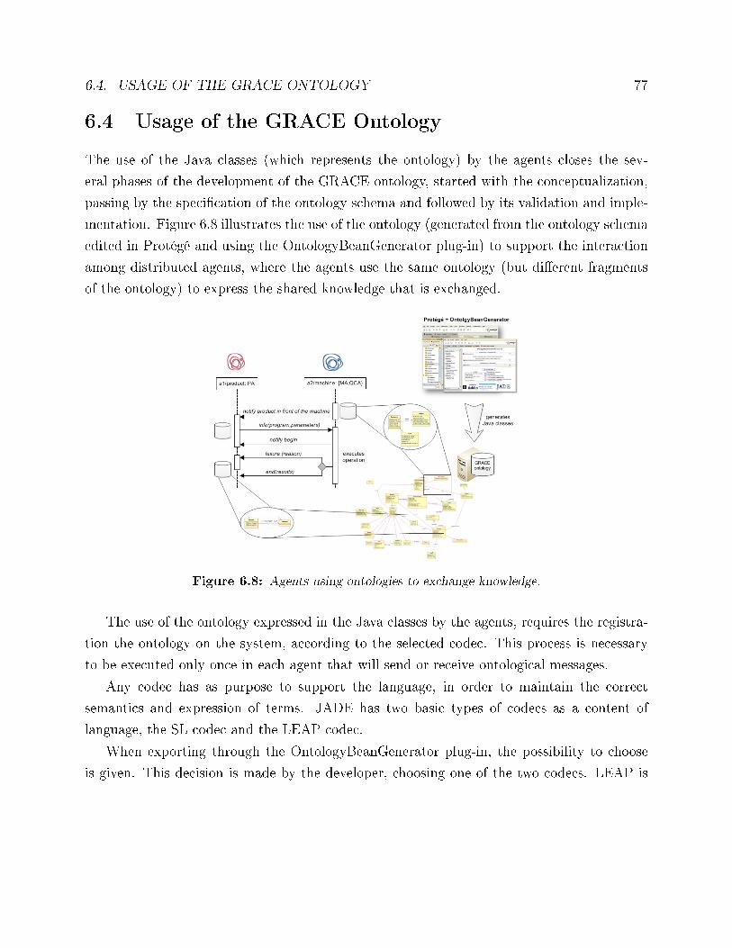
6.4. USAGE OF THE GRACE ONTOLOGY 77
6.4 Usage of the GRACE Ontology
The use of the Java classes (which represents the ontology) by the agents closes the sev-
eral phases of the development of the GRACE ontology, started with the conceptualization,
passing by the speci�cation of the ontology schema and followed by its validation and imple-
mentation. Figure 6.8 illustrates the use of the ontology (generated from the ontology schema
edited in Protégé and using the OntologyBeanGenerator plug-in) to support the interaction
among distributed agents, where the agents use the same ontology (but di�erent fragments
of the ontology) to express the shared knowledge that is exchanged.
Figure 6.8: Agents using ontologies to exchange knowledge.
The use of the ontology expressed in the Java classes by the agents, requires the registra-
tion the ontology on the system, according to the selected codec. This process is necessary
to be executed only once in each agent that will send or receive ontological messages.
Any codec has as purpose to support the language, in order to maintain the correct
semantics and expression of terms. JADE has two basic types of codecs as a content of
language, the SL codec and the LEAP codec.
When exporting through the OntologyBeanGenerator plug-in, the possibility to choose
is given. This decision is made by the developer, choosing one of the two codecs. LEAP is
78CHAPTER 6. INTEGRATION OF THE ONTOLOGY IN THEGRACEMULTI-AGENT SYSTEM
more lightweight, but on the other hand, the content is more readable in SL. It can be said
that LEAP is to be read and interpreted by computers, while the content of SL language
structure is human readable. So the main key to keep is to only use LEAP when there are
strong memory limitations. It would be possible to choose a codec to support an XML-based,
or even if it is the developer interests to implement its language, requiring a codec for it.
In this work, it is used LEAP and the next program illustrates how to register the ontology
on the agents' behaviours.
class WaitingMessages extends CyclicBehaviour implements IConstants, IConstants_GUI {
...
private Codec codec = new LEAPCodec();
//or private Codec codec = new SLCodec();
private Ontology ontology = GraceOntology.getInstance();
WaitingMessages(Agent aThis, boolean myGuiON, formRA_ myGui){ ... }
@Override
public void action()
{
// Register language and ontology
myAgent.getContentManager().registerLanguage(codec);
myAgent.getContentManager().registerOntology(ontology);
ACLMessage msg = myAgent.receive();
Having registered the ontology, the agents can start using the ontology to represent the
knowledge and also to send messages containing this knowledge. Considering the example of
exchanging a message, several steps should be considered.
First, it is necessary to create the ontological message and send it. The next piece of code
illustrates how to create an ontological message structure and send it to other(s) agent(s).
In this case, a PA agent sends a message to a RA.
//ONTOLOGY
//implementacao do _SendOperation
GRACE_Ontology.Operation operation = new DefaultOperation();
operation.addDuration(1); operation.addName(op.getOperation());
//action _SendOperation sendOperation = new Default_SendOperation();
6.4. USAGE OF THE GRACE ONTOLOGY 79
sendOperation.add_sendOperation(operation);
sendOntologyMessage(RA_RECEIVES_PROCESS_PLAN, msg.getSender(),
sendOperation, ACLMessage.INFORM);
...
private boolean sendOntologyMessage(int KONSTANTE, AID receiver,
AgentAction action, int performative){
ACLMessage msg = new ACLMessage(performative);
msg.setLanguage(codec.getName());
msg.setOntology(ontology.getName());
try {
msg.addReceiver(receiver);
msg.setConversationId(((Integer) KONSTANTE).toString());
myAgent.getContentManager().fillContent
(msg,new Action(receiver, action));
myAgent.send(msg);
...
The key issue here is to ful�l the message attribute, namely the setOntology() and set-
Language() methods, and use the FillContent() method to ful�l the content of the message
using the desired ontological object representing the knowledge that PA wants to exchange.
The second step is related to receive the ontological message and parse it. To properly re-
ceive the message, the agent needs to extract the contents with the extractContent() method.
The extracted content of the message is then parsed by comparing the instance type with
the type of value that is expected. In the following piece of code, the result of �if-then� tests
determines which type of instance is the content of the message.
ContentElement content = null;
try {
content = myAgent.getContentManager().extractContent(msg);
Concept action = ((Action) content).getAction();
if (action instanceof _SendOperation) {
_SendOperation sendedOperation = (_SendOperation) action;
GRACE_Ontology.Operation operation =
(GRACE_Ontology.Operation)sendedOperation.get_sendOperation().get(0);
journalDetails.setName(myAgent.getLocalName());
...
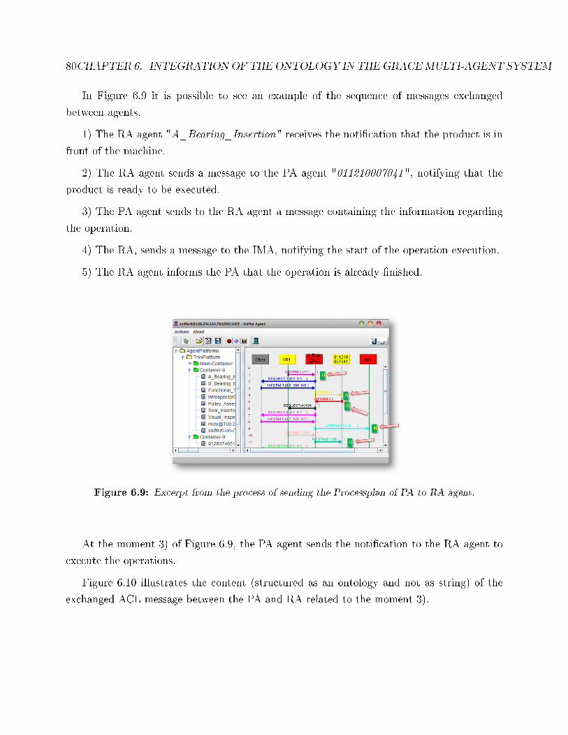
80CHAPTER 6. INTEGRATION OF THE ONTOLOGY IN THEGRACEMULTI-AGENT SYSTEM
In Figure 6.9 it is possible to see an example of the sequence of messages exchanged
between agents.
1) The RA agent "A_Bearing_Insertion" receives the noti�cation that the product is in
front of the machine.
2) The RA agent sends a message to the PA agent "011210007041", notifying that the
product is ready to be executed.
3) The PA agent sends to the RA agent a message containing the information regarding
the operation.
4) The RA, sends a message to the IMA, notifying the start of the operation execution.
5) The RA agent informs the PA that the operation is already �nished.
Figure 6.9: Excerpt from the process of sending the Processplan of PA to RA agent.
At the moment 3) of Figure 6.9, the PA agent sends the noti�cation to the RA agent to
execute the operations.
Figure 6.10 illustrates the content (structured as an ontology and not as string) of the
exchanged ACL message between the PA and RA related to the moment 3).

6.4. USAGE OF THE GRACE ONTOLOGY 81
Figure 6.10: ACL message exchanged between PA and RA agents.
The content of the ACL message sent by the PA to RA requesting for an execution of the
operation is illustrated as following.
((action
(agent-identifier
:name [email protected]:1099/JADE
:addresses (sequence http://Ricardo-PC:7778/acc))
(_SendOperation
:_sendOperation
(sequence (Operation :duration (sequence 1)
:name (sequence Opt_xpto_32_a))))))
The response to this ACL message, also captured by the sni�er tool from the JADE
framework, is illustrated as follows.
((action
(agent-identifier
:name "[email protected]:1099/JADE"
:addresses (sequence http://Ricardo-PC:7778/acc))
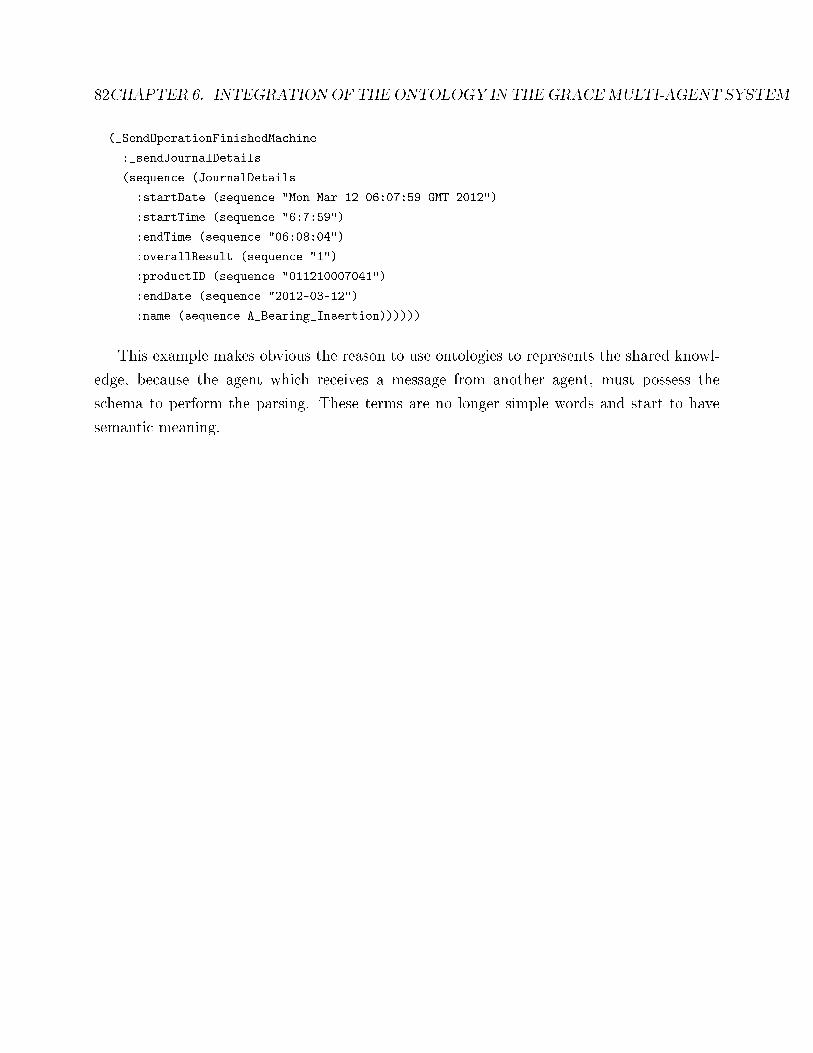
82CHAPTER 6. INTEGRATION OF THE ONTOLOGY IN THEGRACEMULTI-AGENT SYSTEM
(_SendOperationFinishedMachine
:_sendJournalDetails
(sequence (JournalDetails
:startDate (sequence "Mon Mar 12 06:07:59 GMT 2012")
:startTime (sequence "6:7:59")
:endTime (sequence "06:08:04")
:overallResult (sequence "1")
:productID (sequence "011210007041")
:endDate (sequence "2012-03-12")
:name (sequence A_Bearing_Insertion))))))
This example makes obvious the reason to use ontologies to represents the shared knowl-
edge, because the agent which receives a message from another agent, must possess the
schema to perform the parsing. These terms are no longer simple words and start to have
semantic meaning.
Chapter 7
Conclusions and Future Work
The initial objective of the described work is the development of an ontology integrating the
quality and process control for a production line producing washing machines, to be applied
in a multi-agent infrastructure developed for the case. This ontology aims to represent the
knowledge associated to the washing machines production lines domain.
This document accomplishes the last step of the ontologies development process, i.e. the
documentation. It is important that a design ontology has a good documentation support,
which explains in a very simple manner some of the reasons and assumptions taken during
the phases of the development of the ontology. The selected concepts, terms and relationships
should be clari�ed and documented, because some of the terms could be very common and
represent di�erent meanings.
7.1 Conclusion
During this work it was developed a MAS application, to help in this development it was
used the JADE framework. It was also speci�ed ontology to represent the knowledge of the
case study, this speci�cation was developed in Protégé. Finally was integrated the ontology
developed in the system, in order to the agents being able to use the knowledge and share
it among them self. The integration was performed using a plug-in, which accelerates the
process of integration.
83
84 CHAPTER 7. CONCLUSIONS AND FUTURE WORK
This work is relevant, because it aims to contribute to the implementation of such systems
in industrial environments.
However, it is important to refer some of the problems encountered.
The inexistence of a single standard for the ontology was one of the problems, it was
expected to reuse an already present ontology, however it was not possible due to the partic-
ularly of the domain, which required to create a new one re-using some ontological concepts
from existing ontologies. The several meetings with the production line owner allowed con-
sidering advices and obviously the know-how of the concepts, contributing for the correct
construction of the ontology.
The second problem was related to the choice of the approach to be taken for the im-
plementation of the system. In this work, the OntologyBeanGenerator plug-in was used
due to its capability to simplify the implementation process. However, a problem has been
found in the exportation of the last version of the OntologyBeanGenerator plug-in, which
was not performed correctly. Becoming unthinkable to use the old version of the plug-in, it
was necessary to correct it by hand.
The application of this embebed ontology on multi-agent systems to a real-world industrial
application at a production line producing washing machines, will contribute for a proof-of-
concept and a wider adoption of this technologies in industry (MAS and ontologies). The
project ends with an integrator character, since the present study of acquired competencies
has an added value when introduced in real world.
7.2 Future Work
The work described in this document is not a closed cycle and after the implementation of
the designed solution in a real case, it is necessary to move on because in a constant evolution
�eld there are always open points.
The �rst possibility for future work is to create an easy and suitable interface inside the
GRACE MAS infrastructure, to enable the ontology expert's domain to modify the ontology
without the need to interact with ontology engineers, and without the need to know large
technical details, particularly for the ontology instantiation in order to verify and validate
the ontology problems.
7.2. FUTURE WORK 85
Another possible work to do in the future is to change the processes of using the ontology
within the MAS system, in order to infer new knowledge, without having to change the
engineering process again.
Developing a methodology for mapping components that enter the database Bill Of Ma-
terials with processes of ontology. Enhance the ontology to stop giving sustenance to the
knowledge of agents, but for providing services, directing the work into the area of Ontology-
Services in the MAS system.
Any of these referred hypotheses will help to improve and create a system model more
�exible.
86 BIBLIOGRAPHY
[1] Y. Al-Sa� and V. Vyatkin, �An ontology-based recon�guration agent for intelligent
mechatronic systems,� in Proceedings of the 3rd international conference on Industrial
Applications of Holonic and Multi-Agent Systems: Holonic and Multi-Agent Systems for
Manufacturing, HoloMAS '07, (Berlin, Heidelberg), pp. 114�126, Springer-Verlag, 2007.
[2] M. Andreev, G. Rzevski, P. Skobelev, P. Shveykin, A. Tsarev, and A. Tugashev, �Adap-
tive planning for supply chain networks,� in Proceedings of the 3rd international con-
ference on Industrial Applications of Holonic and Multi-Agent Systems: Holonic and
Multi-Agent Systems for Manufacturing, HoloMAS '07, (Berlin, Heidelberg), pp. 215�
224, Springer-Verlag, 2007.
[3] S. Andreev, G. Rzevski, P. Shviekin, P. Skobelev, and I. Yankov, �A multi-agent sched-
uler for rent-a-car companies,� in Proceedings of the 4th International Conference on
Industrial Applications of Holonic and Multi-Agent Systems: Holonic and Multi-Agent
Systems for Manufacturing, HoloMAS '09, (Berlin, Heidelberg), pp. 305�314, Springer-
Verlag, 2009.
[4] P. L. Arnaldo Pereira, Nelson Rodrigues, �Data collection for global monitoring and trend
analysis in the grace multi-agent system,� in International Conference on Industrial
Technology, 2013.
[5] R. Batres, M. West, D. Leal, D. Price, K. Masaki, Y. Shimada, T. Fuchino, and Y. Naka,
�An upper ontology based on iso 15926,� Computers & Chemical Engineering, vol. 31,
pp. 519�534, May 2007.
[6] B. Bauer, J. P. Müller, and J. Odell, �Agent uml: A formalism for specifying multi-
agent interaction,� in IN: CIANCARINI, P.; WOOLDRIDGE, M. [EDS.], AGENT-
ORIENTED SOFTWARE ENGINEERING, pp. 91�103, Springer, 2001.
[7] F. Bellifemine, A. Poggi, and G. Rimassa, �Developing multi-agent systems with jade,�
in Proceedings of the 7th International Workshop on Intelligent Agents VII. Agent Theo-
ries Architectures and Languages, ATAL '00, (London, UK, UK), pp. 89�103, Springer-
Verlag, 2001.
BIBLIOGRAPHY 87
[8] S. Borgo and P. Leitão, �The role of foundational ontologies in manufacturing domain
applications,� in On the Move to Meaningful Internet Systems 2004: CoopIS, DOA, and
ODBASE (R. Meersman and Z. Tari, eds.), vol. 3290 of Lecture Notes in Computer
Science, pp. 670�688, Springer Berlin / Heidelberg, 2004.
[9] P. Bresciani, P. Giorgini, F. Giunchiglia, J. Mylopoulos, and A. Perini, �Tropos: An
agent-oriented software development methodology,� 2003.
[10] H. V. Brussel, J. Wyns, P. Valckenaers, L. Bongaerts, and P. Peeters, �Reference ar-
chitecture for holonic manufacturing systems: Prosa,� in PROSA. COMPUTERS IN
INDUSTRY, pp. 255�274, 1998.
[11] M. Cai, W. Zhang, and K. Zhang, �Manuhub: A semantic web system for ontology-
based service management in distributed manufacturing environments,� Systems, Man
and Cybernetics, Part A: Systems and Humans, IEEE Transactions on, vol. 41, pp. 574
�582, may 2011.
[12] G. Cândido and J. Barata, �A multiagent control system for shop �oor assembly,�
in Holonic and Multi-Agent Systems for Manufacturing (V. Marík, V. Vyatkin, and
A. Colombo, eds.), vol. 4659 of Lecture Notes in Computer Science, pp. 293�302, Springer
Berlin / Heidelberg, 2007.
[13] J. Cardoso, Semantic Web Services: Theory, Tools and Applications. Hershey, PA, USA:
IGI Publishing, 2007.
[14] Óscar Corcho, M. Fernández-López, A. Gómez-Pérez, and Óscar Vicente, �Webode:
An integrated workbench for ontology representation, reasoning, and exchange,� in IN:
PROCEEDINGS OF EKAW 2002. LNCS 2473, pp. 138�153, Springer, 2002.
[15] A. Dvoryanchikova and J. Lastra, �Assessment of the ontological approach in factory au-
tomation from the perspectives of connectionism,� in Emerging Technologies and Factory
Automation, 2007. ETFA. IEEE Conference on, pp. 724 �727, sept. 2007.
[16] A. Farquhar, R. Fikes, and J. Rice, �The ontolingua server: a tool for collaborative
ontology construction,� in International Journal of Human-Computer Studies, 1996.
88 BIBLIOGRAPHY
[17] D. Fensel, Ontologies: A Silver Bullet for Knowledge Management and Electronic Com-
merce. Secaucus, NJ, USA: Springer-Verlag New York, Inc., 2 ed., 2003.
[18] J. Ferber, Multi-Agent Systems: An Introduction to Distributed Arti�cial Intelligence.
Boston, MA, USA: Addison-Wesley Longman Publishing Co., Inc., 1st ed., 1999.
[19] J. Ferber and O. Gutknecht, �Aalaadin: a meta-model for the analysis and design of orga-
nizations in multi-agent systems,� in Proceedings of the Third International Conference
on Multi-Agent Systems, ICMAS'98 (Y. Demazeau, ed.), (Paris, France), pp. 128�135,
IEEE Computer Society, July 1998.
[20] L. Ferrarini, C. Veber, A. Luder, J. Peschke, A. Kalogeras, J. Gialelis, J. Rode, D. Wun-
sch, and V. Chapurlat, �Control architecture for recon�gurable manufacturing systems:
the pabadis'promise approach,� in Emerging Technologies and Factory Automation,
2006. ETFA '06. IEEE Conference on, pp. 545 �552, sept. 2006.
[21] T. Finin, R. Fritzson, D. McKay, and R. McEntire, �Kqml as an agent communica-
tion language,� in Proceedings of the third international conference on Information and
knowledge management, CIKM '94, (New York, NY, USA), pp. 456�463, ACM, 1994.
[22] M. S. Fox, �The tove project towards a common-sense model of the enterprise,� in
Proceedings of the 5th international conference on Industrial and engineering applications
of arti�cial intelligence and expert systems, IEA/AIE '92, (London, UK, UK), pp. 25�34,
Springer-Verlag, 1992.
[23] R. Fujiwara, A. Kitamura, and K. Mutoh, �Ontology-based manufacturing knowledge
navigation platform,� in Intelligent Systems and Informatics (SISY), 2011 IEEE 9th
International Symposium on, pp. 175 �179, sept. 2011.
[24] J. H. Gennari, M. A. Musen, R. W. Fergerson, W. E. Grosso, M. Crubézy, H. Eriksson,
N. F. Noy, and S. W. Tu, �The evolution of protégé: an environment for knowledge-based
systems development,� Int. J. Hum.-Comput. Stud., vol. 58, pp. 89�123, Jan. 2003.
[25] M. Georgoudakis, C. Alexakos, A. Kalogeras, J. Gialelis, and S. Koubias, �Methodology
for the e�cient distribution a manufacturing ontology to a multiagent system utilizing
BIBLIOGRAPHY 89
a relevant meta-ontology,� in Emerging Technologies and Factory Automation, 2007.
ETFA. IEEE Conference on, pp. 1210 �1216, sept. 2007.
[26] M. Georgoudakis, C. Alexakos, A. Kalogeras, J. Gialelis, and S. Koubias, �Decentral-
ized production control through ansi / isa-95 based ontology and agents,� in Factory
Communication Systems, 2006 IEEE International Workshop on, pp. 374 �379, 0-0 2006.
[27] A. Gomez-Perez, �Some ideas and examples to evaluate ontologies,� in Proceedings of
the 11th Conference on Arti�cial Intelligence for Applications, CAIA '95, (Washington,
DC, USA), pp. 299�, IEEE Computer Society, 1995.
[28] M. Grobe, �Rdf, jena, sparql and the 'semantic web',� in Proceedings of the 37th annual
ACM SIGUCCS fall conference, SIGUCCS '09, (New York, NY, USA), pp. 131�138,
ACM, 2009.
[29] T. R. Gruber, �Toward principles for the design of ontologies used for knowledge sharing,�
Int. J. Hum.-Comput. Stud., vol. 43, pp. 907�928, Dec. 1995.
[30] T. R. Gruber, �A translation approach to portable ontology speci�cations,� Knowl.
Acquis., vol. 5, pp. 199�220, June 1993.
[31] M. Grüninger and M. S. Fox, �Methodology for the design and evaluation of ontologies,�
1995.
[32] N. Guarino, Formal Ontology in Information Systems: Proceedings of the 1st Interna-
tional Conference June 6-8, 1998, Trento, Italy. Amsterdam, The Netherlands, The
Netherlands: IOS Press, 1st ed., 1998.
[33] N. Guarino, C. Welty, and E. Common, �Evaluating ontological decisions with onto-
clean,� 2002.
[34] G. van Heijst, A. T. Schreiber, and B. J. Wielinga, �Using explicit ontologies in kbs
development,� Int. J. Hum.-Comput. Stud., vol. 46, pp. 183�292, Mar. 1997.
90 BIBLIOGRAPHY
[35] B. Hellingrath, M. Witthaut, C. Böhle, and S. Brügger, �An organizational knowledge
ontology for automotive supply chains,� in Proceedings of the 4th International Con-
ference on Industrial Applications of Holonic and Multi-Agent Systems: Holonic and
Multi-Agent Systems for Manufacturing, HoloMAS '09, (Berlin, Heidelberg), pp. 37�46,
Springer-Verlag, 2009.
[36] I. Horrocks, �Daml+oil: a description logic for the semantic web,� IEEE Data Engineer-
ing Bulletin, vol. 25, pp. 4�9, 2002.
[37] HP, �Jena - a semantic web framework for java.� available:
http://jena.sourceforge.net/index.html, 2002.
[38] T. Juan, A. Pearce, and L. Sterling, �Roadmap: Extending the gaia methodology for
complex open systems,� pp. 3�10, ACM Press, 2002.
[39] K. Kilian and A. Colin, �A detailed comparison of uml and owl,� tech. rep., Department
for Mathematics and Computer Science, 2005.
[40] H. Knublauch, An Agile Development Methodology for Knowledge-Based Systems In-
cluding a Java Framework for Knowledge Modeling and Appropriate Tool Support. PhD
thesis, University of Ulm, 2002.
[41] K. Kozaki, Y. Kitamura, M. Ikeda, and R. Mizoguchi, �Hozo: An environment for
building/using ontologies based on a fundamental consideration of role and relationship,�
in Proc. of EKAW2002, pp. 213�218, Springer, 2002.
[42] Y. K. Labrou, T. Finin, and Y. Peng, �The current landscape of agent communication
languages,� IEEE Intelligent Systems, vol. 14, March 1999.
[43] M. Laclavík, Z. Balogh, and M. Babík, �Agentowl: Semantic knowledge model and agent
architecture,� in In Computing and Informatics, pp. 419�437.
[44] L. F. Lai, �A knowledge engineering approach to knowledge management,� Inf. Sci.,
vol. 177, pp. 4072�4094, Oct. 2007.
BIBLIOGRAPHY 91
[45] O. Lassila, R. R. Swick, W. Wide, and W. Consortium, �Resource description framework
(rdf) model and syntax speci�cation,� 1998.
[46] P. Leitão, �Agent-based distributed manufacturing control: A state-of-the-art survey,�
Eng. Appl. Artif. Intell., vol. 22, pp. 979�991, Oct. 2009.
[47] P. Leitão and F. Restivo, �Adacor: a holonic architecture for agile and adaptive manu-
facturing control,� Comput. Ind., vol. 57, pp. 121�130, Feb. 2006.
[48] P. Leitao and N. Rodrigues, �Modelling and validating the multi-agent system behaviour
for a washing machine production line,� in Industrial Electronics (ISIE), 2012 IEEE
International Symposium on, pp. 1203 �1208, may 2012.
[49] P. Leitão and N. Rodrigues, �Multi-agent system for on-demand production integrat-
ing production and quality control,� in Proceedings of the 5th international conference
on Industrial applications of holonic and multi-agent systems for manufacturing, Holo-
MAS'11, (Berlin, Heidelberg), pp. 84�93, Springer-Verlag, 2011.
[50] S. Lemaignan, A. Siadat, J.-Y. Dantan, and A. Semenenko, �Mason: A proposal for
an ontology of manufacturing domain,� in Distributed Intelligent Systems: Collective
Intelligence and Its Applications, 2006. DIS 2006. IEEE Workshop on, pp. 195 �200,
june 2006.
[51] R. Leszczyna, �Evaluation of agent platforms.� June 2004.
[52] P. L. N. P. Lorenzo Stroppa, Nelson Rodrigues, �Quality control agents for adaptive
visual inspection in production lines,� in IEEE Industrial Electronics Society (IECON),
2012.
[53] A. Lozano-Tello and A. Gómez-Pérez, �Ontometric: A method to choose the appropriate
ontology,� 2004.
[54] M. Luck, �50 facts about agent-based computing agentlink iii,� tech. rep., School of
Electronics and Computer Science University of Southampton, 2005.
92 BIBLIOGRAPHY
[55] F. Macia-Perez, V. Gilart-Iglesias, A. Ferrandiz-Colmeiro, J. Berna-Martinez, and
J. Gea-Martinez, �New models of agile manufacturing assisted by semantic,� in Enter-
prise Distributed Object Computing Conference Workshops, 2009. EDOCW 2009. 13th,
pp. 336 �343, sept. 2009.
[56] C. Mclean, Y. T. Lee, G. Shao, and F. Riddick, �Shop data model and interface speci�-
cation,� in NISTIR 7198, National Institute of Standards and Technology, 2005.
[57] M. Merdan, G. Koppensteiner, I. Hegny, and B. Favre-Bulle, �Application of an ontology
in a transport domain,� in Industrial Technology, 2008. ICIT 2008. IEEE International
Conference on, pp. 1 �6, april 2008.
[58] n.n, �Deliverable d1.2- speci�cation of the multi-agent architecture for line-production
system, integrating process and quality control,� 2011.
[59] n.n, �Deliverable d1.3- document de�ning the ontology for line-production system, inte-
grating process and quality control,� 2011.
[60] n.n, �Deliverable d4.1- document de�ning the engineering process reference model,� 2011.
[61] R. Neches, R. Fikes, T. Finin, T. Gruber, R. Patil, T. Senator, and W. R. Swartout,
�Enabling technology for knowledge sharing,� AI Mag., vol. 12, pp. 36�56, Sept. 1991.
[62] G. Ning, J. Tian-guo, and L. Wen-jian, �Research on manufacturing resource domain
ontology integration based on owl,� in Database Technology and Applications (DBTA),
2010 2nd International Workshop on, pp. 1 �4, nov. 2010.
[63] N. F. Noy and D. L. Mcguinness, �Ontology development 101: A guide to creating your
�rst ontology,� tech. rep., 2001.
[64] H. S. Nwana, D. T. Ndumu, L. C. Lee, and J. C. Collis, �Zeus: a toolkit and approach for
building distributed multi-agent systems,� in Proceedings of the third annual conference
on Autonomous Agents, AGENTS '99, (New York, NY, USA), pp. 360�361, ACM, 1999.
[65] M. Obitko and V. Marík, �Adding owl semantics to ontologies used in multi-agent sys-
tems for manufacturing,� in HoloMAS'03, pp. 189�200, 2003.
BIBLIOGRAPHY 93
[66] M. Obitko and V. Marík, �Ontologies for multi-agent systems in manufacturing domain,�
in Proceedings of the 13th International Workshop on Database and Expert Systems
Applications, DEXA '02, (Washington, DC, USA), pp. 597�602, IEEE Computer Society,
2002.
[67] O. J. L. Orozco and J. L. M. Lastra, �Using semantic web technologies to describe
automation objects,� International Journal of Manufacturing Research, vol. 1, no. 4,
pp. 482�503, 2007.
[68] L. Padgham and M. Winiko�, Developing intelligent agent systems: a practical guide.
Wiley series in agent technology, John Wiley, 2004.
[69] C. A. Petri, Kommunikation mit Automaten. PhD thesis, Bonn: Institut für Instru-
mentelle Mathematik, Schriften des IIM Nr. 2, 1962. Second Edition:, New York: Gri�-
iss Air Force Base, Technical Report RADC-TR-65�377, Vol.1, 1966, Pages: Suppl. 1,
English translation.
[70] M. Reyes Perez, J. Gausemeier, and D. Nordsiek, �Ontology development for a manu-
facturing data base for products with graded properties,� in Information, Process, and
Knowledge Management, 2009. eKNOW '09. International Conference on, pp. 105 �109,
feb. 2009.
[71] J. Rumbaugh, I. Jacobson, and G. Booch, Uni�ed Modeling Language Reference Manual,
The (2nd Edition). Pearson Higher Education, 2004.
[72] S. J. Russell and P. Norvig, Arti�cial Intelligence: A Modern Approach. Pearson Edu-
cation, 2 ed., 2003.
[73] G. Schreiber, H. Akkermans, A. Anjewierden, R. Dehoog, N. Shadbolt, W. Vande-
velde, and B. Wielinga, Knowledge Engineering and Management: The CommonKADS
Methodology. The MIT Press, Dec. 1999.
[74] J. R. Searle, Speech Acts: An Essay in the Philosophy of Language. Cambridge University
Press, Jan. 1970.
94 BIBLIOGRAPHY
[75] M. P. Singh, �Agent communication languages: Rethinking the principles,� Computer,
vol. 31, pp. 40�47, Dec. 1998.
[76] Y. Sure, M. Erdmann, J. Angele, S. Staab, R. Studer, and D. Wenke, �Ontoedit: Col-
laborative ontology development for the semantic web,� pp. 221�235, Springer, 2002.
[77] A. Treytl, B. Khan, and T. Wagner, �Interoperable language family for agent interaction
in industrial applications,� in Emerging Technologies and Factory Automation, 2007.
ETFA. IEEE Conference on, pp. 863 �871, sept. 2007.
[78] M. Uschold, �Ontologies and database schema wat's the di�erence.�.
[79] M. Uschold, V. R. Benjamins, B. Ch, A. Gomez-perez, N. Guarino, and R. Jasper, �A
framework for understanding and classifying ontology applications,� 1999.
[80] M. Uschold, M. Gruninger, M. Uschold, and M. Gruninger, �Ontologies: Principles,
methods and applications,� Knowledge Engineering Review, vol. 11, pp. 93�136, 1996.
[81] P. Vrba, �Java-based agent platform evaluation,� LECTURE NOTES IN COMPUTER
SCIENCE, pp. 47�58, 2003.
[82] P. Vrba, M. Radakovic, M. Obitko, and V. Marik, �Semantic technologies: latest ad-
vances in agent-based manufacturing control systems,� International Journal of Produc-
tion Research, vol. 49, no. 5, pp. 1483�1496, 2011.
[83] V. Vyatkin, J. Christensen, J. Lastra, and F. Auinger, �Oooneida: an open, object-
oriented knowledge economy for intelligent distributed automation,� in Industrial Infor-
matics, 2003. INDIN 2003. Proceedings. IEEE International Conference on, pp. 79 � 88,
aug. 2003.
[84] W3C, �(owl) web ontology language reference,� W3C recommendation, W3C, Feb. 2004.
[85] K. Wang and S. Tong, �An ontology of manufacturing knowledge for design decision sup-
port,� in Wireless Communications, Networking and Mobile Computing, 2008. WiCOM
'08. 4th International Conference on, pp. 1 �5, oct. 2008.
BIBLIOGRAPHY 95
[86] D. Waralak and V. Siricharoen, �Ontologies and object models in object oriented software
engineering.�
[87] M. Wooldridge, N. R. Jennings, and D. Kinny, �The gaia methodology for agent-oriented
analysis and design,� Autonomous Agents and Multi-Agent Systems, vol. 3, pp. 285�312,
Sept. 2000.
[88] M. J. Woolridge, Introduction to Multiagent Systems. New York, NY, USA: John Wiley
and; Sons, Inc., 2002.
[89] J. Zhou and R. Dieng-Kuntz, �Manufacturing ontology analysis and design: towards
excellent manufacturing,� in Industrial Informatics, 2004. INDIN '04. 2004 2nd IEEE
International Conference on, pp. 39 �45, june 2004.
[90] V. Mak, P. Vrba, and P. Leito, eds., Holonic and Multi-Agent Systems for Manufacturing
- 5th International Conference on Industrial Applications of Holonic and Multi-Agent
Systems, HoloMAS 2011, Toulouse, France, August 29-31, 2011. Proceedings, vol. 6867
of Lecture Notes in Computer Science, Springer, 2011.
[91] G. Weiss, ed., Multiagent systems: a modern approach to distributed arti�cial intelli-
gence. Cambridge, MA, USA: MIT Press, 1999.

96 BIBLIOGRAPHY
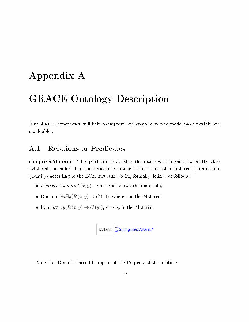
Appendix A
GRACE Ontology Description
Any of these hypotheses, will help to improve and create a system model more �exible and
mouldable .
A.1 Relations or Predicates
comprisesMaterial This predicate establishes the recursive relation between the class
�Material�, meaning that a material or component consists of other materials (in a certain
quantity) according to the BOM structure, being formally de�ned as follows:
• comprisesMaterial (x, y)the material x uses the material y.
• Domain: ∀x∃y(R (x, y)→ C (x)), where x is the Material.
• Range:∀x, y(R (x, y)→ C (y)), wherey is the Material.
Note that R and C intend to represent the Property of the relations.
97
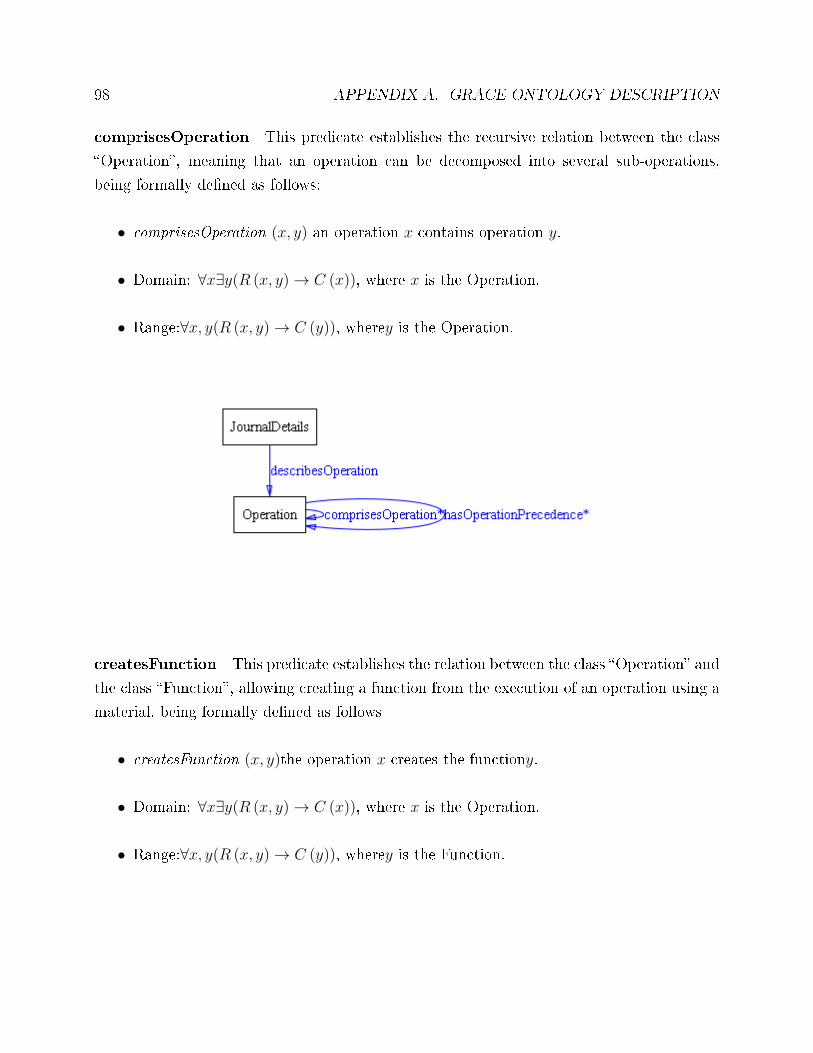
98 APPENDIX A. GRACE ONTOLOGY DESCRIPTION
comprisesOperation This predicate establishes the recursive relation between the class
�Operation�, meaning that an operation can be decomposed into several sub-operations,
being formally de�ned as follows:
• comprisesOperation (x, y) an operation x contains operation y.
• Domain: ∀x∃y(R (x, y)→ C (x)), where x is the Operation.
• Range:∀x, y(R (x, y)→ C (y)), wherey is the Operation.
createsFunction This predicate establishes the relation between the class �Operation� and
the class �Function�, allowing creating a function from the execution of an operation using a
material, being formally de�ned as follows
• createsFunction (x, y)the operation x creates the functiony.
• Domain: ∀x∃y(R (x, y)→ C (x)), where x is the Operation.
• Range:∀x, y(R (x, y)→ C (y)), wherey is the Function.
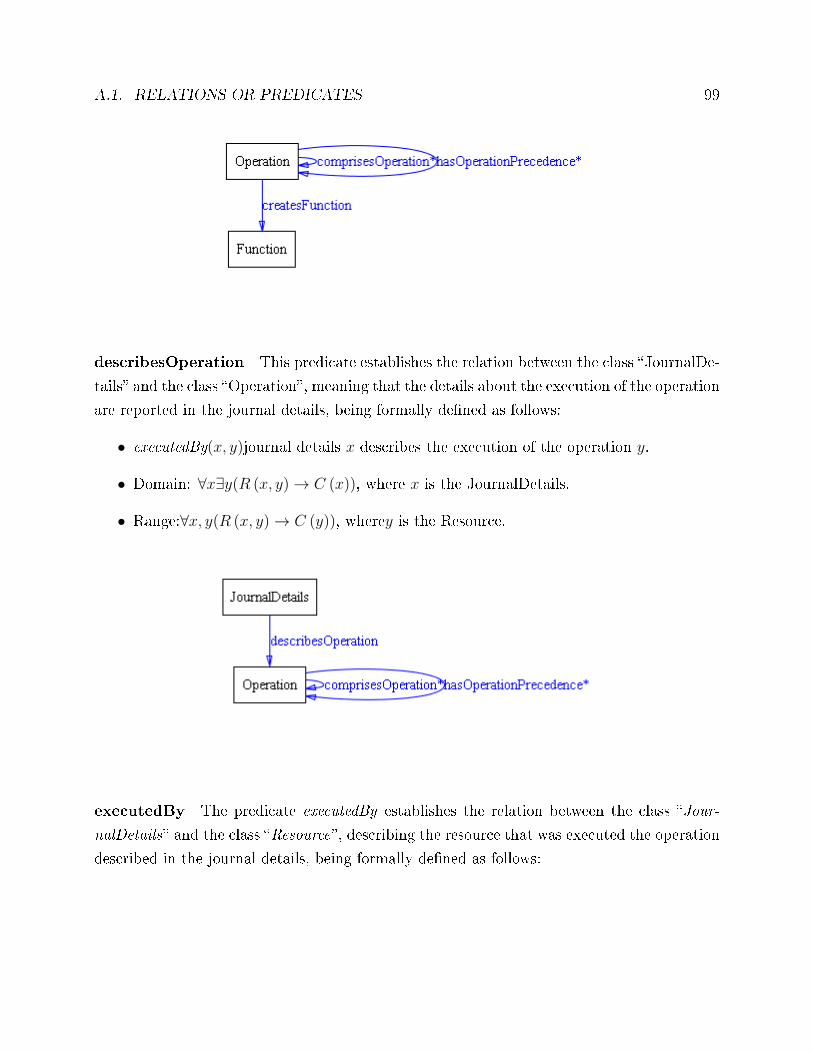
A.1. RELATIONS OR PREDICATES 99
describesOperation This predicate establishes the relation between the class �JournalDe-
tails� and the class �Operation�, meaning that the details about the execution of the operation
are reported in the journal details, being formally de�ned as follows:
• executedBy(x, y)journal details x describes the execution of the operation y.
• Domain: ∀x∃y(R (x, y)→ C (x)), where x is the JournalDetails.
• Range:∀x, y(R (x, y)→ C (y)), wherey is the Resource.
executedBy The predicate executedBy establishes the relation between the class �Jour-
nalDetails� and the class �Resource�, describing the resource that was executed the operation
described in the journal details, being formally de�ned as follows:
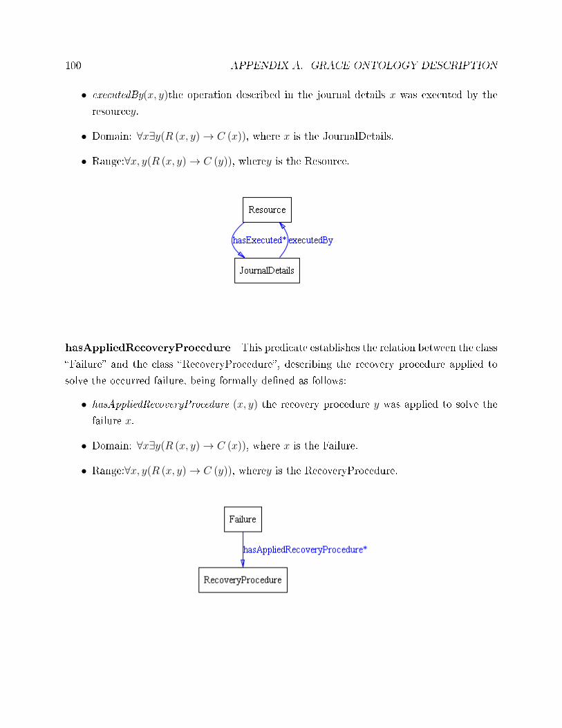
100 APPENDIX A. GRACE ONTOLOGY DESCRIPTION
• executedBy(x, y)the operation described in the journal details x was executed by the
resourcey.
• Domain: ∀x∃y(R (x, y)→ C (x)), where x is the JournalDetails.
• Range:∀x, y(R (x, y)→ C (y)), wherey is the Resource.
hasAppliedRecoveryProcedure This predicate establishes the relation between the class
�Failure� and the class �RecoveryProcedure�, describing the recovery procedure applied to
solve the occurred failure, being formally de�ned as follows:
• hasAppliedRecoveryProcedure (x, y) the recovery procedure y was applied to solve the
failure x.
• Domain: ∀x∃y(R (x, y)→ C (x)), where x is the Failure.
• Range:∀x, y(R (x, y)→ C (y)), wherey is the RecoveryProcedure.
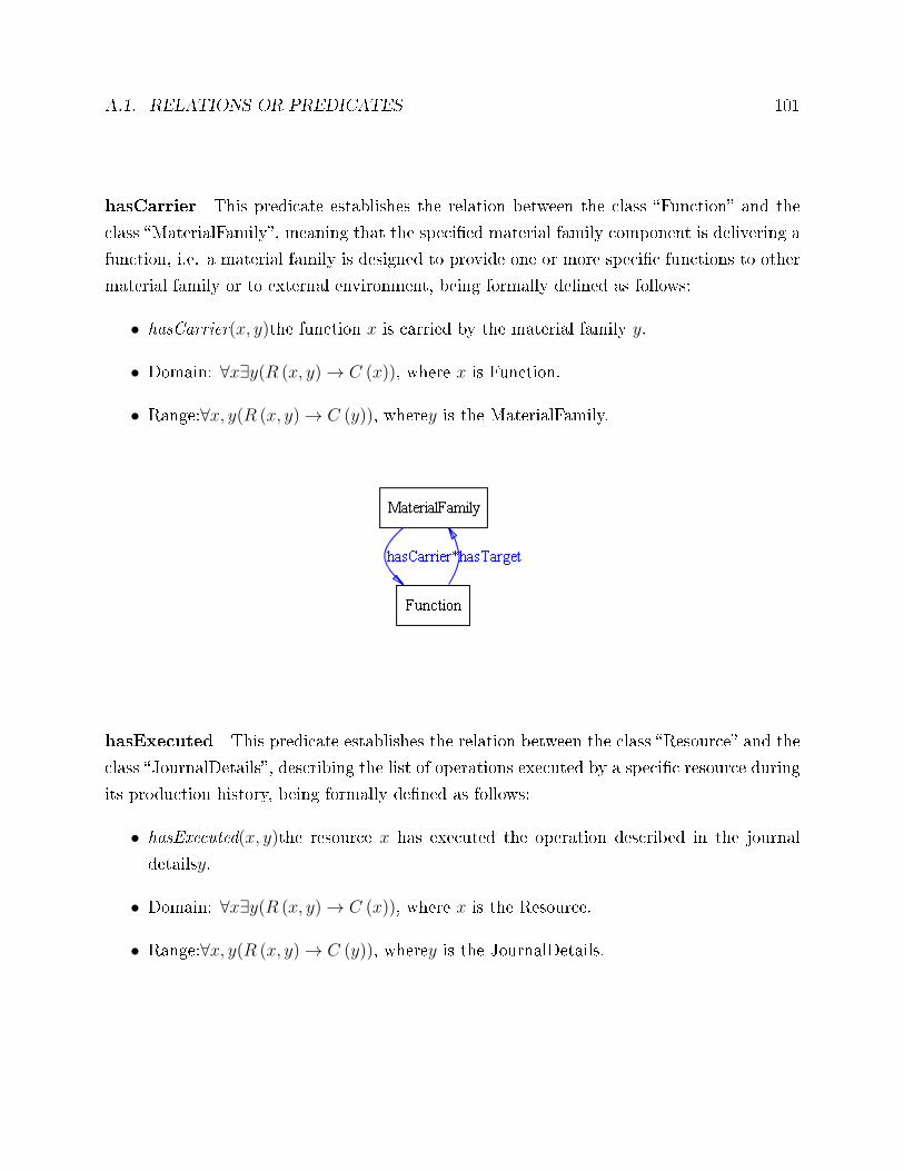
A.1. RELATIONS OR PREDICATES 101
hasCarrier This predicate establishes the relation between the class �Function� and the
class �MaterialFamily�, meaning that the speci�ed material family component is delivering a
function, i.e. a material family is designed to provide one or more speci�c functions to other
material family or to external environment, being formally de�ned as follows:
• hasCarrier(x, y)the function x is carried by the material family y.
• Domain: ∀x∃y(R (x, y)→ C (x)), where x is Function.
• Range:∀x, y(R (x, y)→ C (y)), wherey is the MaterialFamily.
hasExecuted This predicate establishes the relation between the class �Resource� and the
class �JournalDetails�, describing the list of operations executed by a speci�c resource during
its production history, being formally de�ned as follows:
• hasExecuted(x, y)the resource x has executed the operation described in the journal
detailsy.
• Domain: ∀x∃y(R (x, y)→ C (x)), where x is the Resource.
• Range:∀x, y(R (x, y)→ C (y)), wherey is the JournalDetails.
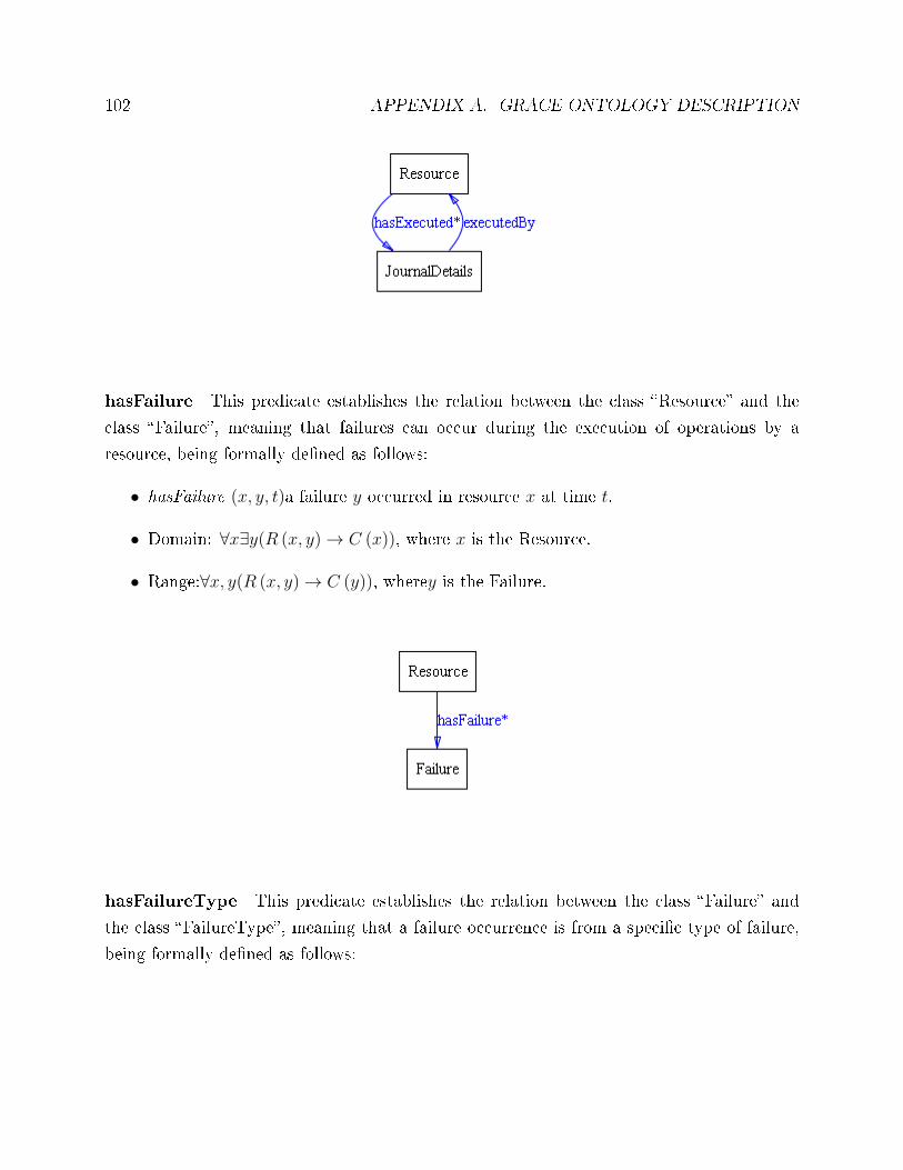
102 APPENDIX A. GRACE ONTOLOGY DESCRIPTION
hasFailure This predicate establishes the relation between the class �Resource� and the
class �Failure�, meaning that failures can occur during the execution of operations by a
resource, being formally de�ned as follows:
• hasFailure (x, y, t)a failure y occurred in resource x at time t.
• Domain: ∀x∃y(R (x, y)→ C (x)), where x is the Resource.
• Range:∀x, y(R (x, y)→ C (y)), wherey is the Failure.
hasFailureType This predicate establishes the relation between the class �Failure� and
the class �FailureType�, meaning that a failure occurrence is from a speci�c type of failure,
being formally de�ned as follows:
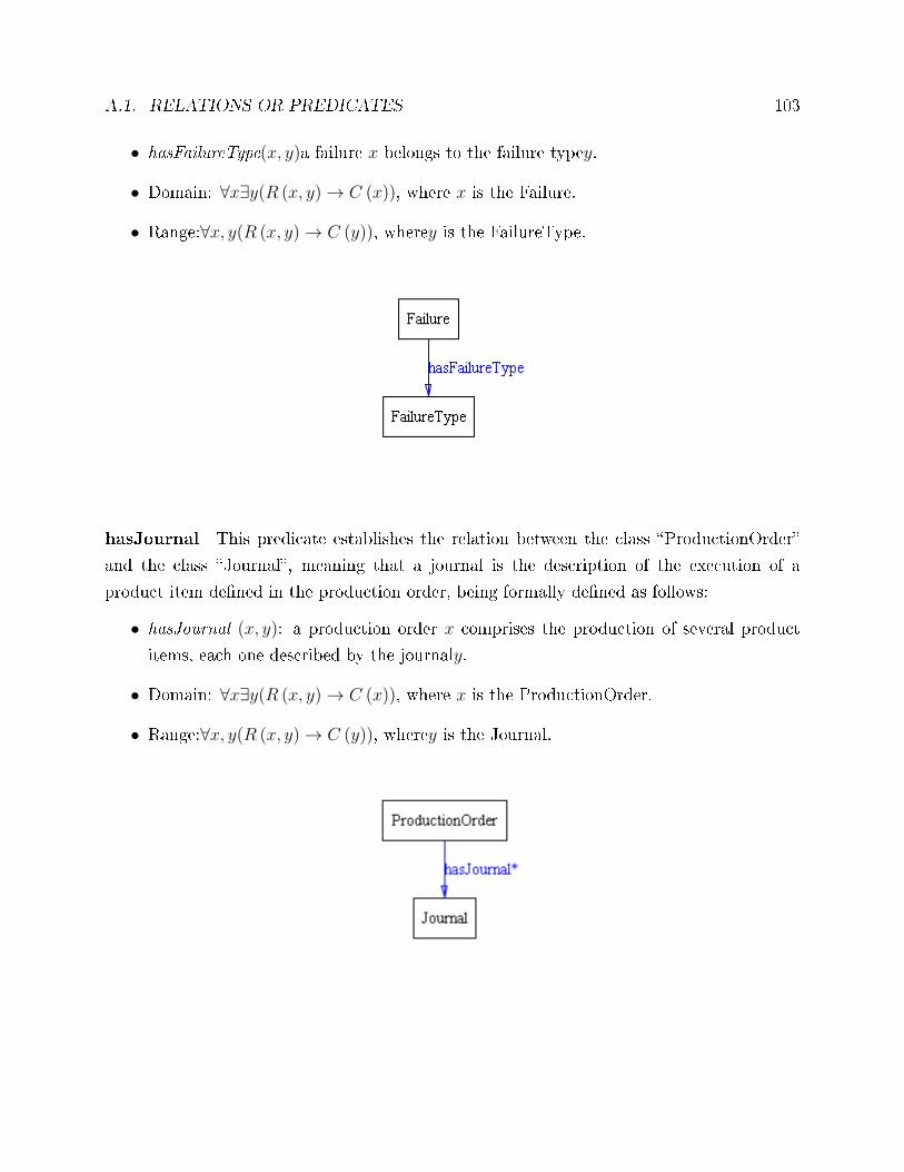
A.1. RELATIONS OR PREDICATES 103
• hasFailureType(x, y)a failure x belongs to the failure typey.
• Domain: ∀x∃y(R (x, y)→ C (x)), where x is the Failure.
• Range:∀x, y(R (x, y)→ C (y)), wherey is the FailureType.
hasJournal This predicate establishes the relation between the class �ProductionOrder�
and the class �Journal�, meaning that a journal is the description of the execution of a
product item de�ned in the production order, being formally de�ned as follows:
• hasJournal (x, y): a production order x comprises the production of several product
items, each one described by the journaly.
• Domain: ∀x∃y(R (x, y)→ C (x)), where x is the ProductionOrder.
• Range:∀x, y(R (x, y)→ C (y)), wherey is the Journal.
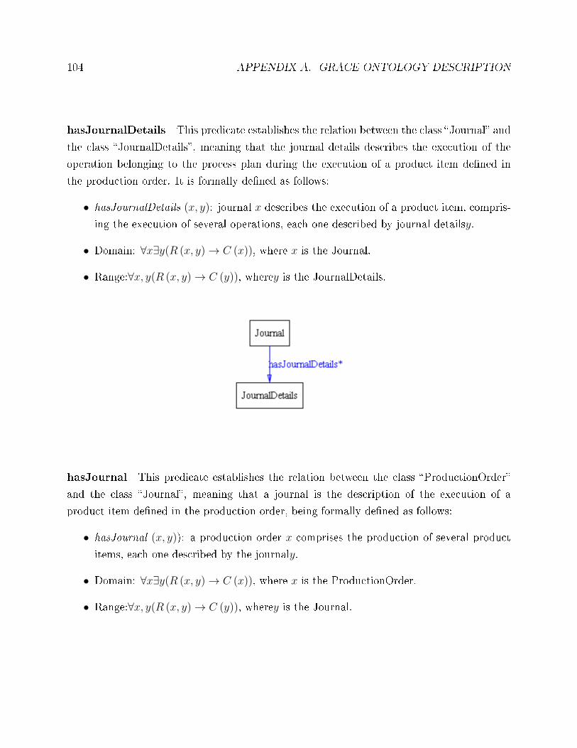
104 APPENDIX A. GRACE ONTOLOGY DESCRIPTION
hasJournalDetails This predicate establishes the relation between the class �Journal� and
the class �JournalDetails�, meaning that the journal details describes the execution of the
operation belonging to the process plan during the execution of a product item de�ned in
the production order. It is formally de�ned as follows:
• hasJournalDetails (x, y): journal x describes the execution of a product item, compris-
ing the execution of several operations, each one described by journal detailsy.
• Domain: ∀x∃y(R (x, y)→ C (x)), where x is the Journal.
• Range:∀x, y(R (x, y)→ C (y)), wherey is the JournalDetails.
hasJournal This predicate establishes the relation between the class �ProductionOrder�
and the class �Journal�, meaning that a journal is the description of the execution of a
product item de�ned in the production order, being formally de�ned as follows:
• hasJournal (x, y)): a production order x comprises the production of several product
items, each one described by the journaly.
• Domain: ∀x∃y(R (x, y)→ C (x)), where x is the ProductionOrder.
• Range:∀x, y(R (x, y)→ C (y)), wherey is the Journal.
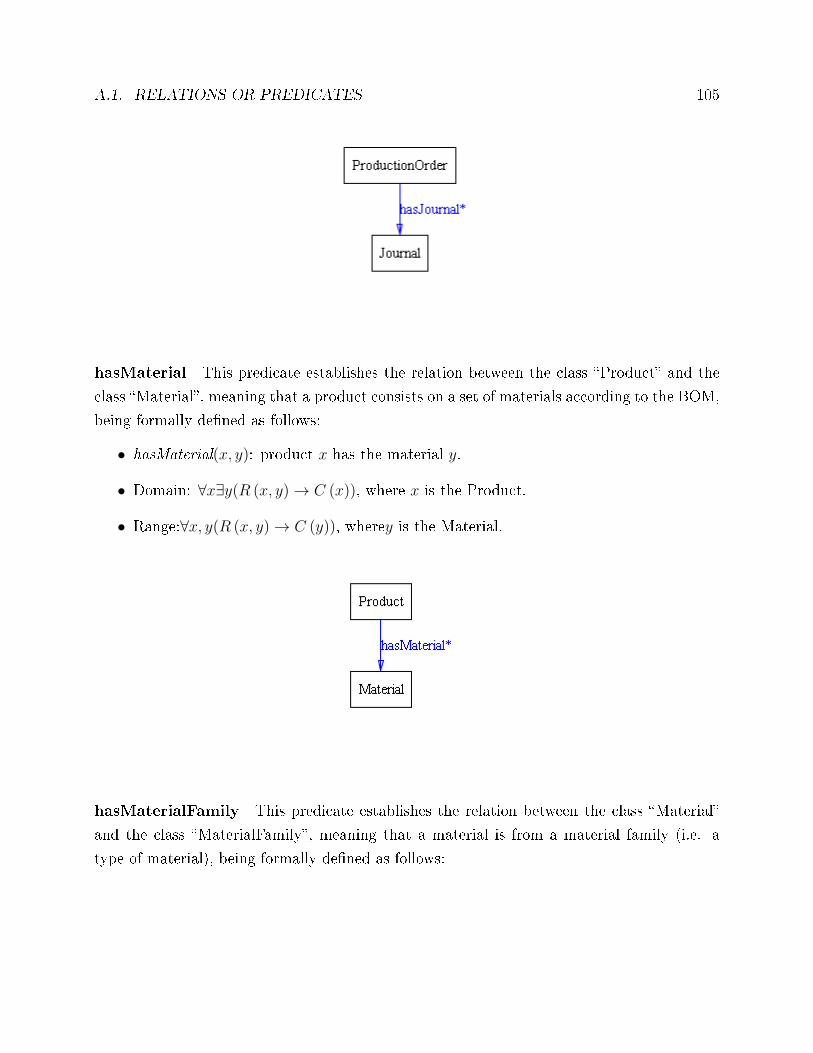
A.1. RELATIONS OR PREDICATES 105
hasMaterial This predicate establishes the relation between the class �Product� and the
class �Material�, meaning that a product consists on a set of materials according to the BOM,
being formally de�ned as follows:
• hasMaterial(x, y): product x has the material y.
• Domain: ∀x∃y(R (x, y)→ C (x)), where x is the Product.
• Range:∀x, y(R (x, y)→ C (y)), wherey is the Material.
hasMaterialFamily This predicate establishes the relation between the class �Material�
and the class �MaterialFamily�, meaning that a material is from a material family (i.e. a
type of material), being formally de�ned as follows:
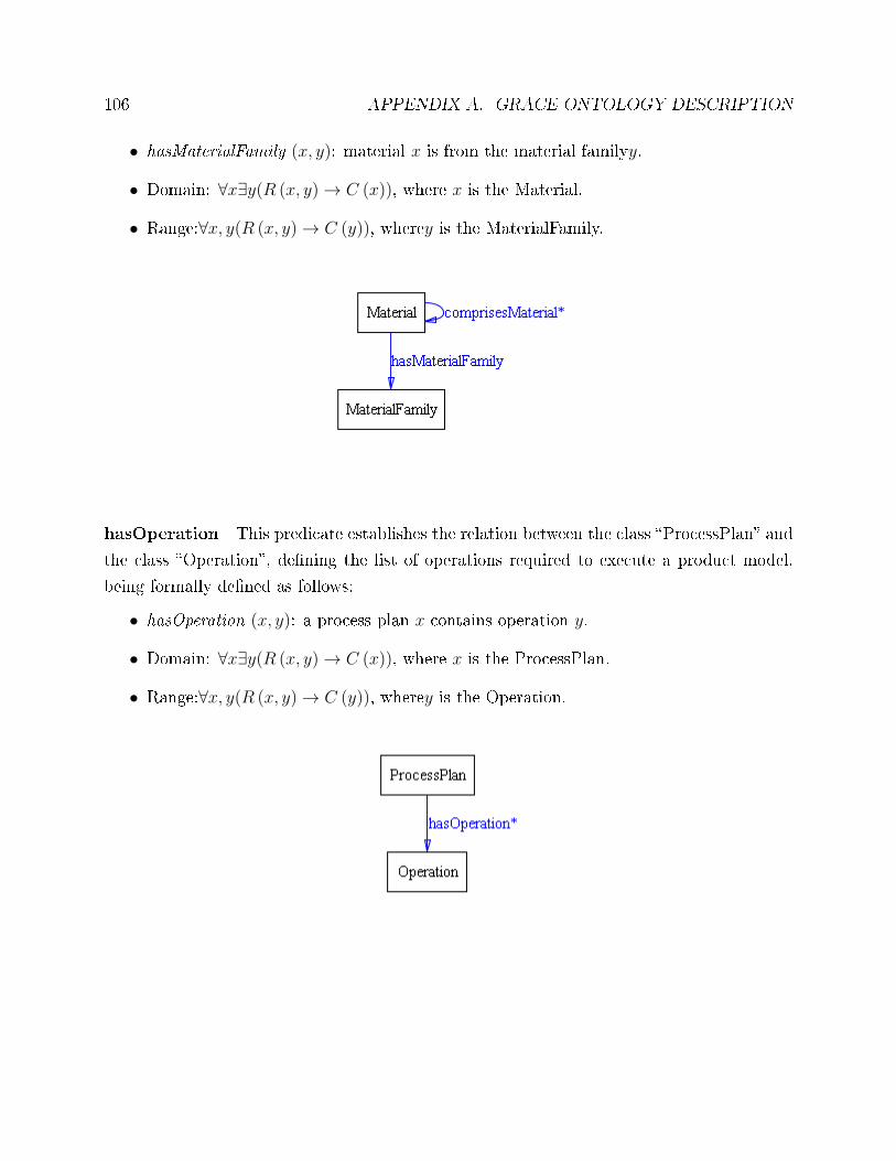
106 APPENDIX A. GRACE ONTOLOGY DESCRIPTION
• hasMaterialFamily (x, y): material x is from the material familyy.
• Domain: ∀x∃y(R (x, y)→ C (x)), where x is the Material.
• Range:∀x, y(R (x, y)→ C (y)), wherey is the MaterialFamily.
hasOperation This predicate establishes the relation between the class �ProcessPlan� and
the class �Operation�, de�ning the list of operations required to execute a product model,
being formally de�ned as follows:
• hasOperation (x, y): a process plan x contains operation y.
• Domain: ∀x∃y(R (x, y)→ C (x)), where x is the ProcessPlan.
• Range:∀x, y(R (x, y)→ C (y)), wherey is the Operation.
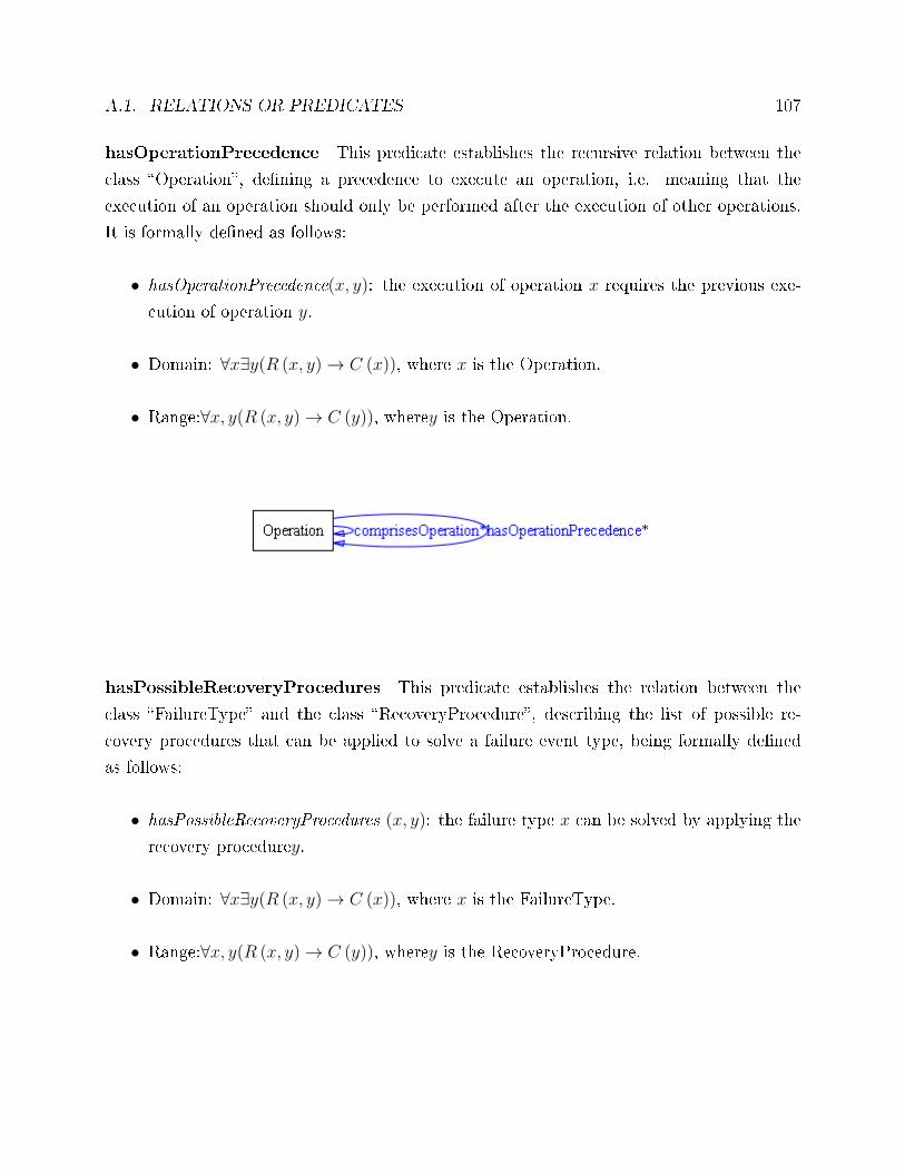
A.1. RELATIONS OR PREDICATES 107
hasOperationPrecedence This predicate establishes the recursive relation between the
class �Operation�, de�ning a precedence to execute an operation, i.e. meaning that the
execution of an operation should only be performed after the execution of other operations.
It is formally de�ned as follows:
• hasOperationPrecedence(x, y): the execution of operation x requires the previous exe-
cution of operation y.
• Domain: ∀x∃y(R (x, y)→ C (x)), where x is the Operation.
• Range:∀x, y(R (x, y)→ C (y)), wherey is the Operation.
hasPossibleRecoveryProcedures This predicate establishes the relation between the
class �FailureType� and the class �RecoveryProcedure�, describing the list of possible re-
covery procedures that can be applied to solve a failure event type, being formally de�ned
as follows:
• hasPossibleRecoveryProcedures (x, y): the failure type x can be solved by applying the
recovery procedurey.
• Domain: ∀x∃y(R (x, y)→ C (x)), where x is the FailureType.
• Range:∀x, y(R (x, y)→ C (y)), wherey is the RecoveryProcedure.
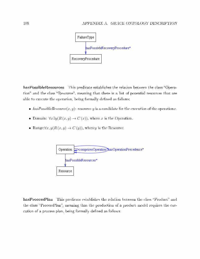
108 APPENDIX A. GRACE ONTOLOGY DESCRIPTION
hasPossibleResources This predicate establishes the relation between the class �Opera-
tion� and the class �Resource�, meaning that there is a list of potential resources that are
able to execute the operation, being formally de�ned as follows:
• hasPossibleResource(x, y): resource y is a candidate for the execution of the operationx.
• Domain: ∀x∃y(R (x, y)→ C (x)), where x is the Operation.
• Range:∀x, y(R (x, y)→ C (y)), wherey is the Resource.
hasProcessPlan This predicate establishes the relation between the class �Product� and
the class �ProcessPlan�, meaning that the production of a product model requires the exe-
cution of a process plan, being formally de�ned as follows:
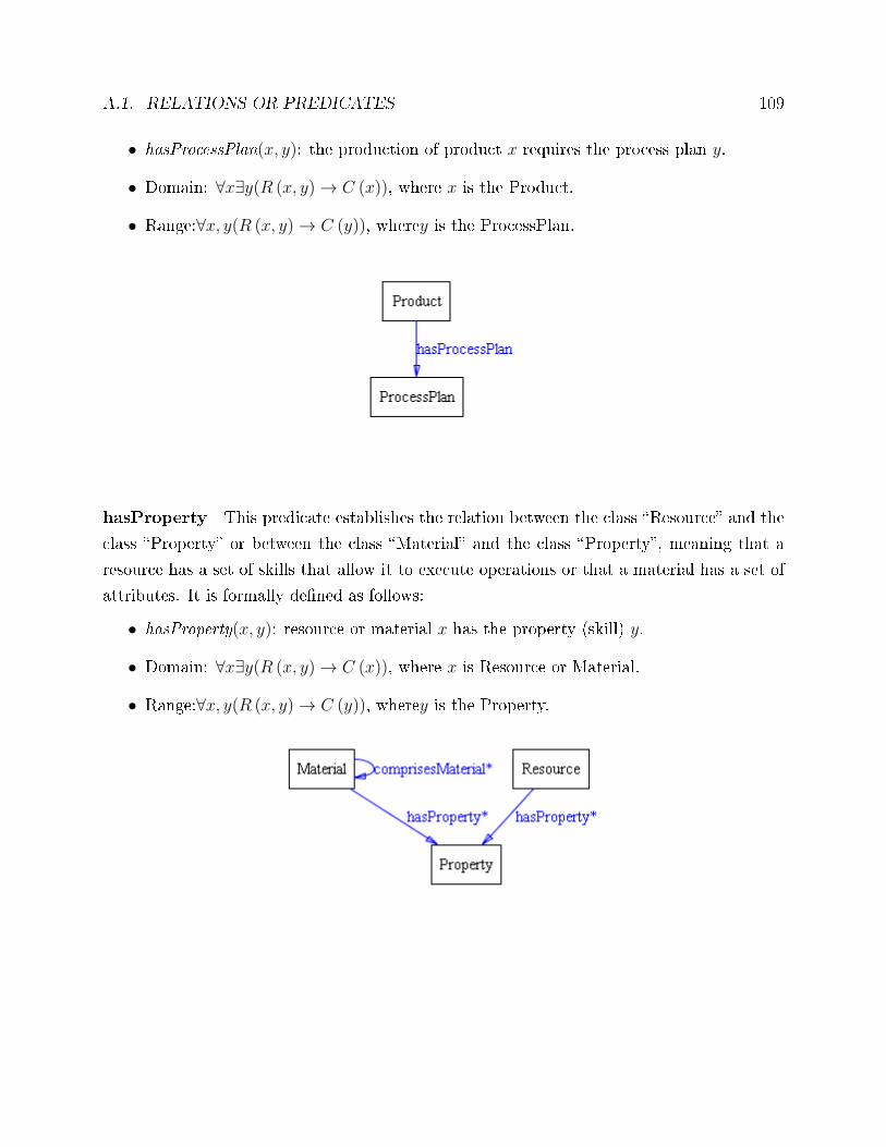
A.1. RELATIONS OR PREDICATES 109
• hasProcessPlan(x, y): the production of product x requires the process plan y.
• Domain: ∀x∃y(R (x, y)→ C (x)), where x is the Product.
• Range:∀x, y(R (x, y)→ C (y)), wherey is the ProcessPlan.
hasProperty This predicate establishes the relation between the class �Resource� and the
class �Property� or between the class �Material� and the class �Property�, meaning that a
resource has a set of skills that allow it to execute operations or that a material has a set of
attributes. It is formally de�ned as follows:
• hasProperty(x, y): resource or material x has the property (skill) y.
• Domain: ∀x∃y(R (x, y)→ C (x)), where x is Resource or Material.
• Range:∀x, y(R (x, y)→ C (y)), wherey is the Property.
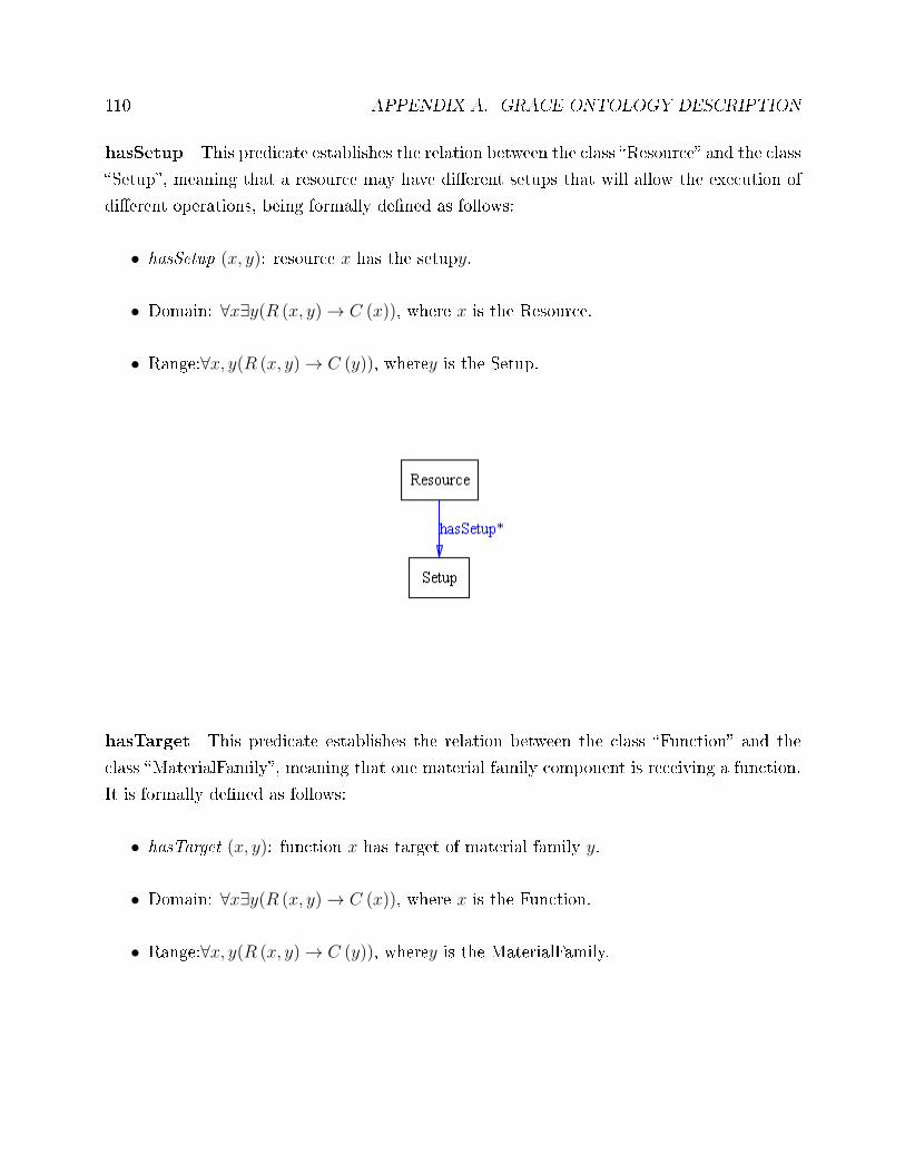
110 APPENDIX A. GRACE ONTOLOGY DESCRIPTION
hasSetup This predicate establishes the relation between the class �Resource� and the class
�Setup�, meaning that a resource may have di�erent setups that will allow the execution of
di�erent operations, being formally de�ned as follows:
• hasSetup (x, y): resource x has the setupy.
• Domain: ∀x∃y(R (x, y)→ C (x)), where x is the Resource.
• Range:∀x, y(R (x, y)→ C (y)), wherey is the Setup.
hasTarget This predicate establishes the relation between the class �Function� and the
class �MaterialFamily�, meaning that one material family component is receiving a function.
It is formally de�ned as follows:
• hasTarget (x, y): function x has target of material family y.
• Domain: ∀x∃y(R (x, y)→ C (x)), where x is the Function.
• Range:∀x, y(R (x, y)→ C (y)), wherey is the MaterialFamily.
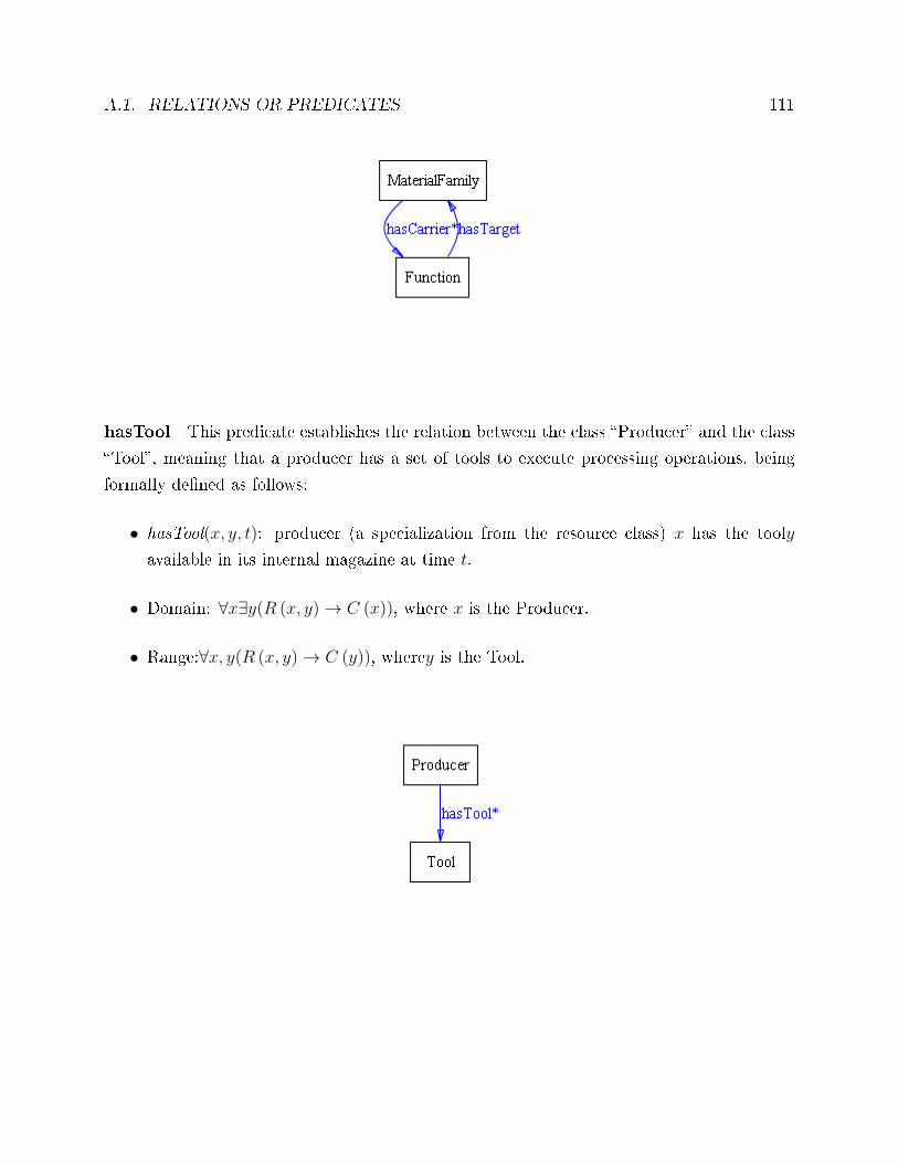
A.1. RELATIONS OR PREDICATES 111
hasTool This predicate establishes the relation between the class �Producer� and the class
�Tool�, meaning that a producer has a set of tools to execute processing operations, being
formally de�ned as follows:
• hasTool(x, y, t): producer (a specialization from the resource class) x has the tooly
available in its internal magazine at time t.
• Domain: ∀x∃y(R (x, y)→ C (x)), where x is the Producer.
• Range:∀x, y(R (x, y)→ C (y)), wherey is the Tool.
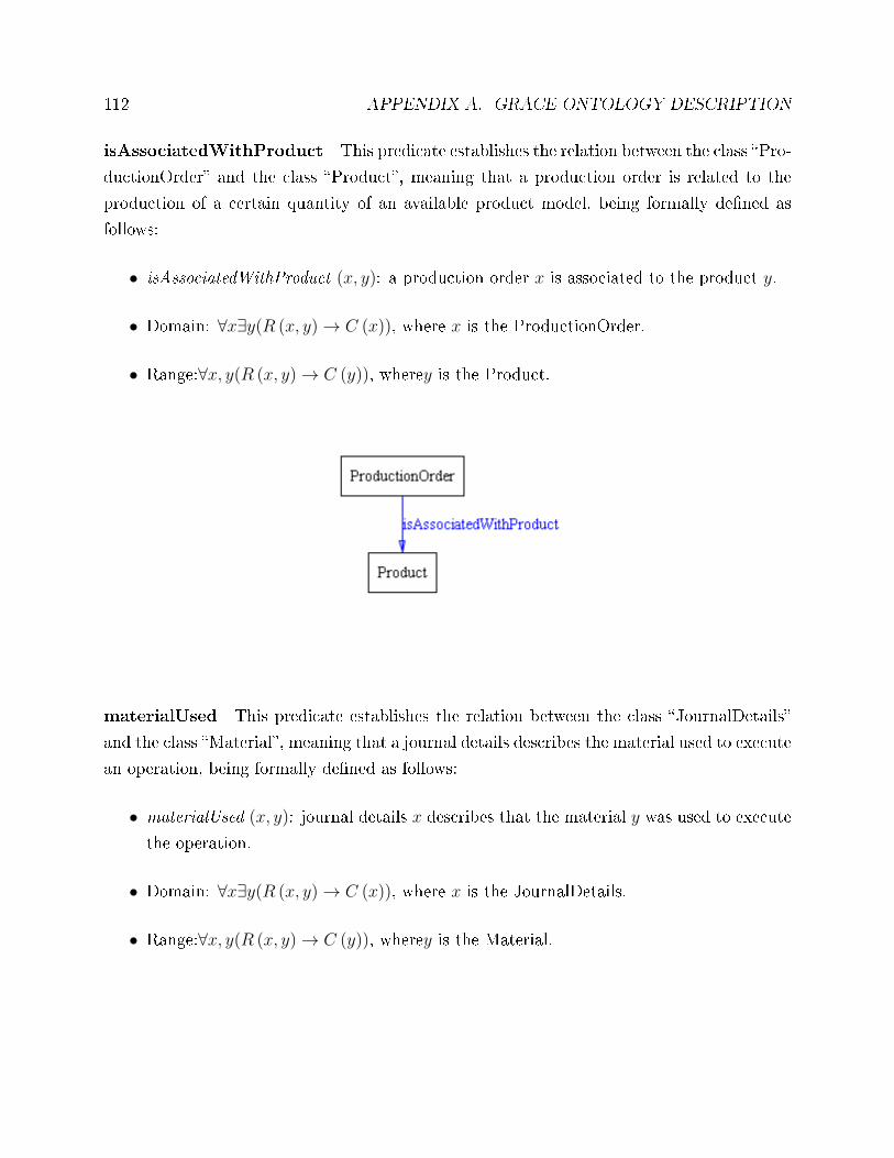
112 APPENDIX A. GRACE ONTOLOGY DESCRIPTION
isAssociatedWithProduct This predicate establishes the relation between the class �Pro-
ductionOrder� and the class �Product�, meaning that a production order is related to the
production of a certain quantity of an available product model, being formally de�ned as
follows:
• isAssociatedWithProduct (x, y): a production order x is associated to the product y.
• Domain: ∀x∃y(R (x, y)→ C (x)), where x is the ProductionOrder.
• Range:∀x, y(R (x, y)→ C (y)), wherey is the Product.
materialUsed This predicate establishes the relation between the class �JournalDetails�
and the class �Material�, meaning that a journal details describes the material used to execute
an operation, being formally de�ned as follows:
• materialUsed (x, y): journal details x describes that the material y was used to execute
the operation.
• Domain: ∀x∃y(R (x, y)→ C (x)), where x is the JournalDetails.
• Range:∀x, y(R (x, y)→ C (y)), wherey is the Material.
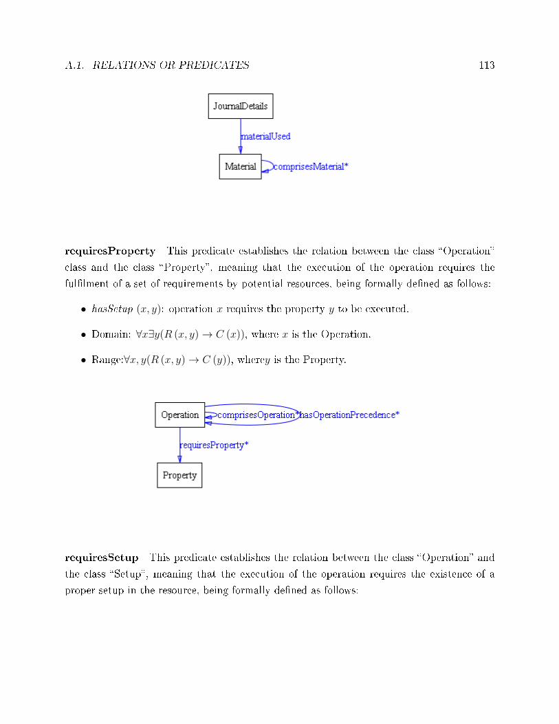
A.1. RELATIONS OR PREDICATES 113
requiresProperty This predicate establishes the relation between the class �Operation�
class and the class �Property�, meaning that the execution of the operation requires the
ful�lment of a set of requirements by potential resources, being formally de�ned as follows:
• hasSetup (x, y): operation x requires the property y to be executed.
• Domain: ∀x∃y(R (x, y)→ C (x)), where x is the Operation.
• Range:∀x, y(R (x, y)→ C (y)), wherey is the Property.
requiresSetup This predicate establishes the relation between the class �Operation� and
the class �Setup�, meaning that the execution of the operation requires the existence of a
proper setup in the resource, being formally de�ned as follows:
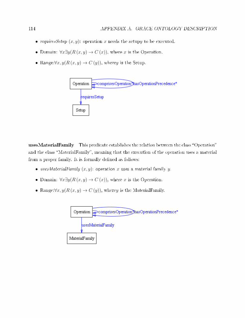
114 APPENDIX A. GRACE ONTOLOGY DESCRIPTION
• requiresSetup (x, y): operation x needs the setupy to be executed.
• Domain: ∀x∃y(R (x, y)→ C (x)), where x is the Operation.
• Range:∀x, y(R (x, y)→ C (y)), wherey is the Setup.
usesMaterialFamily This predicate establishes the relation between the class �Operation�
and the class �MaterialFamily�, meaning that the execution of the operation uses a material
from a proper family. It is formally de�ned as follows:
• usesMaterialFamily (x, y): operation x uses a material family y.
• Domain: ∀x∃y(R (x, y)→ C (x)), where x is the Operation.
• Range:∀x, y(R (x, y)→ C (y)), wherey is the MaterialFamily.
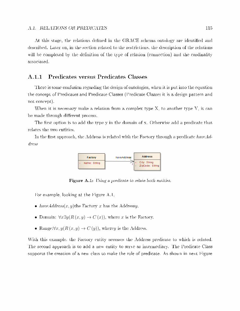
A.1. RELATIONS OR PREDICATES 115
At this stage, the relations de�ned in the GRACE schema ontology are identi�ed and
described. Later on, in the section related to the restrictions, the description of the relations
will be completed by the de�nition of the type of relation (connection) and the cardinality
associated.
A.1.1 Predicates versus Predicates Classes
There is some confusion regarding the design of ontologies, when it is put into the equation
the concept of Predicates and Predicate Classes (Predicate Classes it is a design pattern and
not concept).
When it is necessary make a relation from a complex type X, to another type Y, it can
be made through di�erent process.
The �rst option is to add the type y in the domain of x. Otherwise add a predicate that
relates the two entities.
In the �rst approach, the Address is related with the Factory through a predicate haveAd-
dress
Figure A.1: Using a predicate to relate both entities.
For example, looking at the Figure A.1,
• haveAddress(x, y)the Factory x has the Addressy.
• Domain: ∀x∃y(R (x, y)→ C (x)), where x is the Factory.
• Range:∀x, y(R (x, y)→ C (y)), wherey is the Address.
With this example, the Factory entity accesses the Address predicate to which is related.
The second approach is to add a new entity to serve as intermediary. The Predicate Class
supports the creation of a new class to make the role of predicate. As shown in next Figure
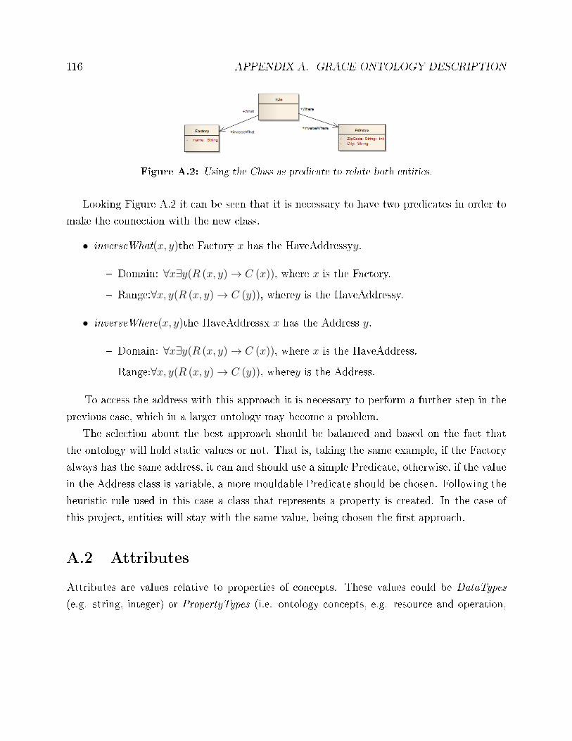
116 APPENDIX A. GRACE ONTOLOGY DESCRIPTION
Figure A.2: Using the Class as predicate to relate both entities.
Looking Figure A.2 it can be seen that it is necessary to have two predicates in order to
make the connection with the new class.
• inverseWhat(x, y)the Factory x has the HaveAddressyy.
� Domain: ∀x∃y(R (x, y)→ C (x)), where x is the Factory.
� Range:∀x, y(R (x, y)→ C (y)), wherey is the HaveAddressy.
• inverseWhere(x, y)the HaveAddressx x has the Address y.
� Domain: ∀x∃y(R (x, y)→ C (x)), where x is the HaveAddress.
� Range:∀x, y(R (x, y)→ C (y)), wherey is the Address.
To access the address with this approach it is necessary to perform a further step in the
previous case, which in a larger ontology may become a problem.
The selection about the best approach should be balanced and based on the fact that
the ontology will hold static values or not. That is, taking the same example, if the Factory
always has the same address, it can and should use a simple Predicate, otherwise, if the value
in the Address class is variable, a more mouldable Predicate should be chosen. Following the
heuristic rule used in this case a class that represents a property is created. In the case of
this project, entities will stay with the same value, being chosen the �rst approach.
A.2 Attributes
Attributes are values relative to properties of concepts. These values could be DataTypes
(e.g. string, integer) or PropertyTypes (i.e. ontology concepts, e.g. resource and operation,
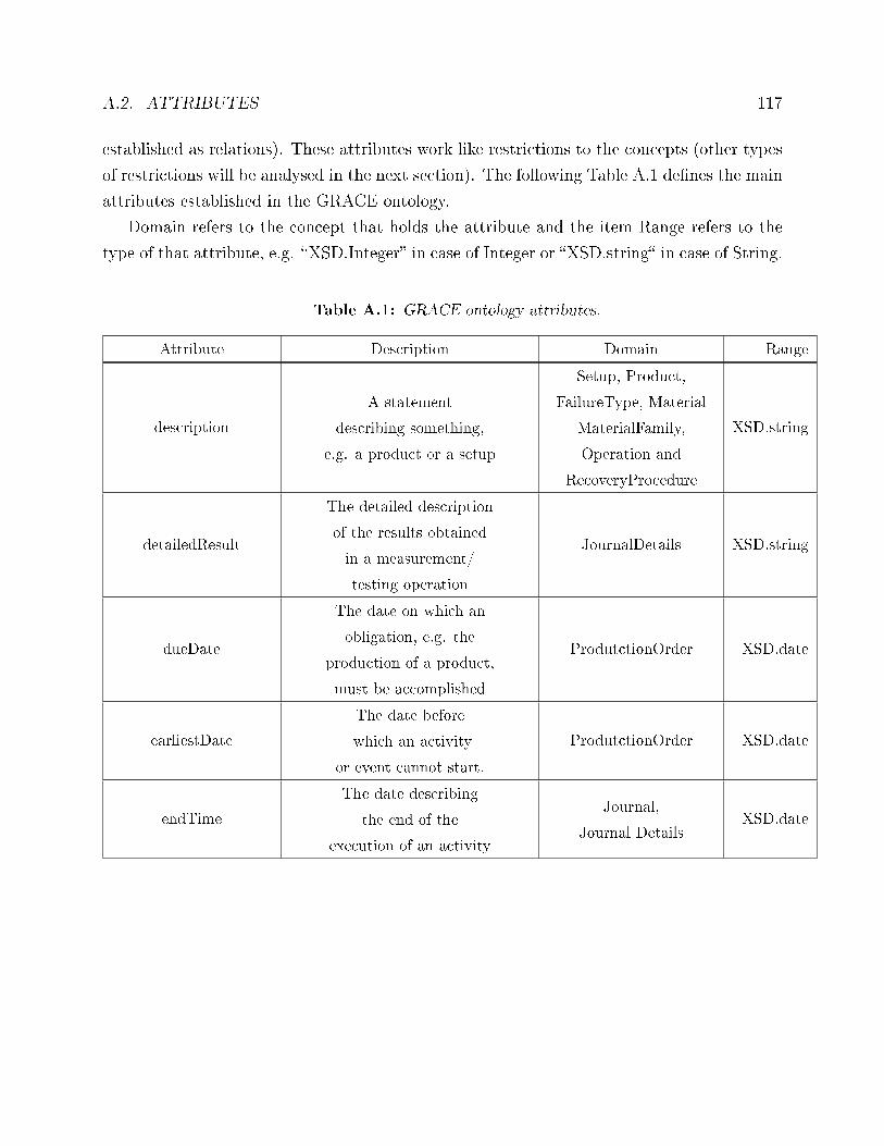
A.2. ATTRIBUTES 117
established as relations). These attributes work like restrictions to the concepts (other types
of restrictions will be analysed in the next section). The following Table A.1 de�nes the main
attributes established in the GRACE ontology.
Domain refers to the concept that holds the attribute and the item Range refers to the
type of that attribute, e.g. �XSD.Integer� in case of Integer or �XSD.string� in case of String.
Table A.1: GRACE ontology attributes.
Attribute Description Domain Range
description
A statement
describing something,
e.g. a product or a setup
Setup, Product,
FailureType, Material
MaterialFamily,
Operation and
RecoveryProcedure
XSD.string
detailedResult
The detailed description
of the results obtained
in a measurement/
testing operation
JournalDetails XSD.string
dueDate
The date on which an
obligation, e.g. the
production of a product,
must be accomplished
ProdutctionOrder XSD.date
earliestDate
The date before
which an activity
or event cannot start.
ProdutctionOrder XSD.date
endTime
The date describing
the end of the
execution of an activity
Journal,
Journal DetailsXSD.date
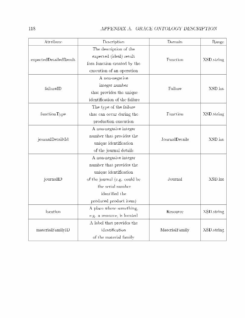
118 APPENDIX A. GRACE ONTOLOGY DESCRIPTION
Attribute Description Domain Range
expectedDetailedResult
The description of the
expected (ideal) result
fora function created by the
execution of an operation
Function XSD.string
failureID
A non-negative
integer number
that provides the unique
identi�cation of the failure
Failure XSD.int
functionType
The type of the failure
that can occur during the
production execution
Function XSD.string
journalDetailsId
A non-negative integer
number that provides the
unique identi�cation
of the journal details
JournalDetails XSD.int
journalID
A non-negative integer
number that provides the
unique identi�cation
of the journal (e.g. could be
the serial number
identi�ed the
produced product item)
Journal XSD.int
locationA place where something,
e.g. a resource, is locatedResource XSD.string
materialFamilyID
A label that provides the
identi�cation
of the material family
MaterialFamily XSD.string
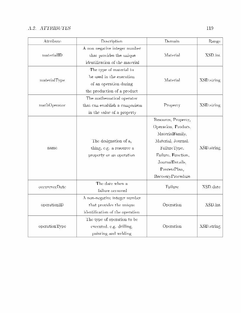
A.2. ATTRIBUTES 119
Attribute Description Domain Range
materialID
A non-negative integer number
that provides the unique
identi�cation of the material
Material XSD.int
materialType
The type of material to
be used in the execution
of an operation during
the production of a product
Material XSD.string
mathOperator
The mathematical operator
that can establish a comparison
in the value of a property
Property XSD.string
name
The designation of a,
thing, e.g. a resource a
property or an operation
Resource, Property,
Operation, Product,
MaterialFamily,
Material, Journal,
FailureType,
Failure, Function,
JournalDetails,
ProcessPlan,
RecoveryProcedure
XSD.string
occurenceDateThe date when a
failure occurredFailure XSD.date
operationID
A non-negative integer number
that provides the unique
identi�cation of the operation
Operation XSD.int
operationType
The type of operation to be
executed, e.g. drilling,
painting and welding
Operation XSD.string
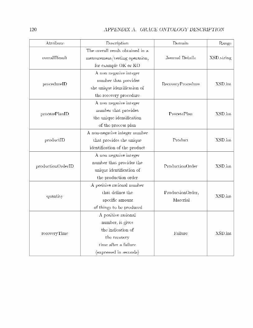
120 APPENDIX A. GRACE ONTOLOGY DESCRIPTION
Attribute Description Domain Range
overallResult
The overall result obtained in a
measurement/testing operation,
for example OK or KO
Journal Details XSD.string
procedureID
A non-negative integer
number that provides
the unique identi�cation of
the recovery procedure
RecoveryProcedure XSD.int
processPlanID
A non-negative integer
number that provides
the unique identi�cation
of the process plan
ProcessPlan XSD.int
productID
A non-negative integer number
that provides the unique
identi�cation of the product
Product XSD.int
productionOrderID
A non-negative integer
number that provides the
unique identi�cation of
the production order
ProductionOrder XSD.int
quantity
A positive rational number
that de�nes the
speci�c amount
of things to be produced
ProductionOrder,
MaterialXSD.int
recoveryTime
A positive rational
number, it gives
the indication of
the recovery
time after a failure
(expressed in seconds)
Failure XSD.int
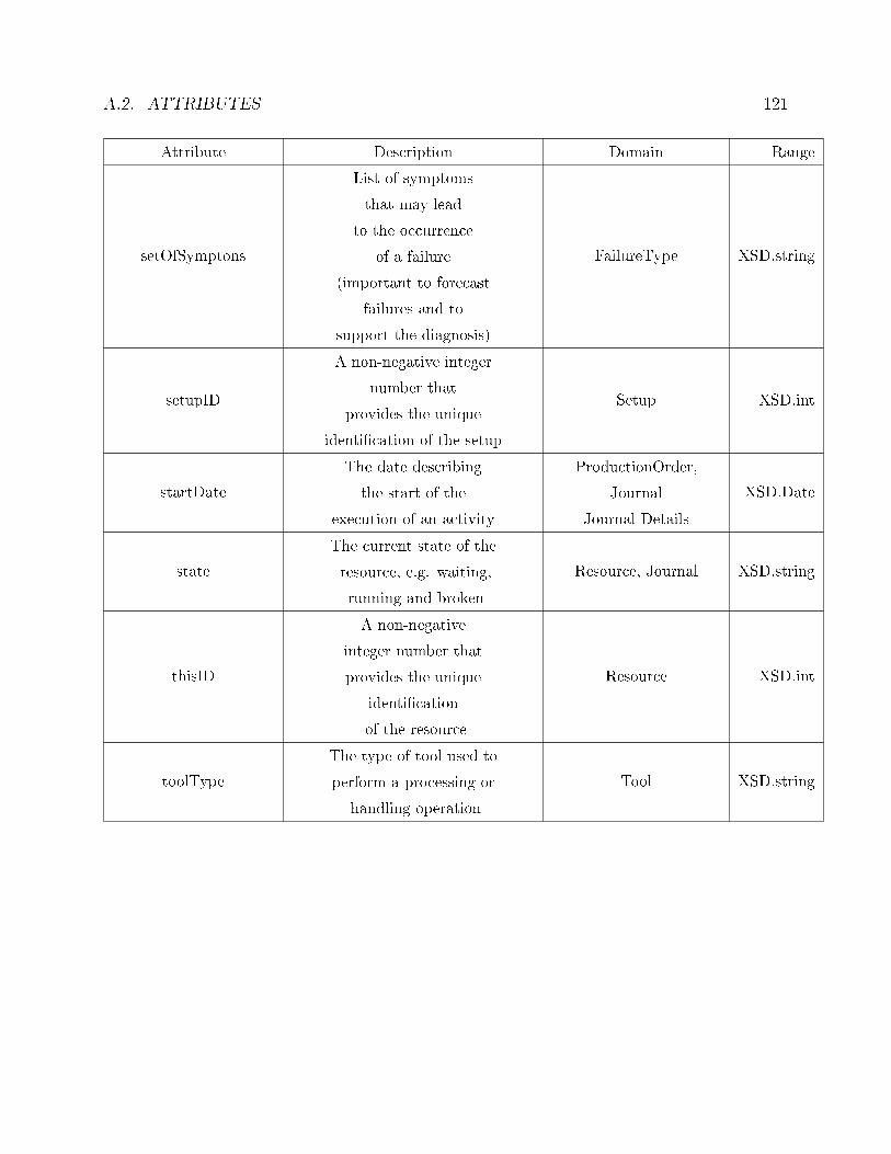
A.2. ATTRIBUTES 121
Attribute Description Domain Range
setOfSymptons
List of symptoms
that may lead
to the occurrence
of a failure
(important to forecast
failures and to
support the diagnosis)
FailureType XSD.string
setupID
A non-negative integer
number that
provides the unique
identi�cation of the setup
Setup XSD.int
startDate
The date describing
the start of the
execution of an activity
ProductionOrder,
Journal
Journal Details
XSD.Date
state
The current state of the
resource, e.g. waiting,
running and broken
Resource, Journal XSD.string
thisID
A non-negative
integer number that
provides the unique
identi�cation
of the resource
Resource XSD.int
toolType
The type of tool used to
perform a processing or
handling operation
Tool XSD.string
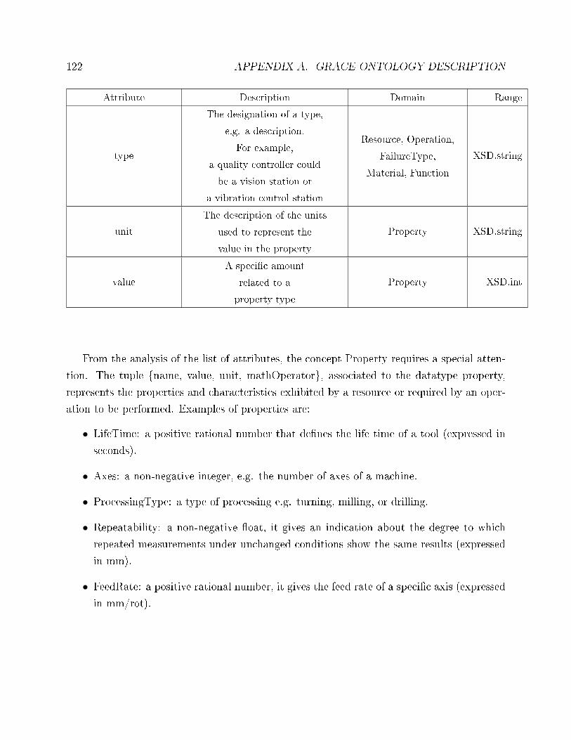
122 APPENDIX A. GRACE ONTOLOGY DESCRIPTION
Attribute Description Domain Range
type
The designation of a type,
e.g. a description.
For example,
a quality controller could
be a vision station or
a vibration control station
Resource, Operation,
FailureType,
Material, Function
XSD.string
unit
The description of the units
used to represent the
value in the property
Property XSD.string
value
A speci�c amount
related to a
property type
Property XSD.int
From the analysis of the list of attributes, the concept Property requires a special atten-
tion. The tuple {name, value, unit, mathOperator}, associated to the datatype property,
represents the properties and characteristics exhibited by a resource or required by an oper-
ation to be performed. Examples of properties are:
• LifeTime: a positive rational number that de�nes the life time of a tool (expressed in
seconds).
• Axes: a non-negative integer, e.g. the number of axes of a machine.
• ProcessingType: a type of processing e.g. turning, milling, or drilling.
• Repeatability: a non-negative �oat, it gives an indication about the degree to which
repeated measurements under unchanged conditions show the same results (expressed
in mm).
• FeedRate: a positive rational number, it gives the feed rate of a speci�c axis (expressed
in mm/rot).
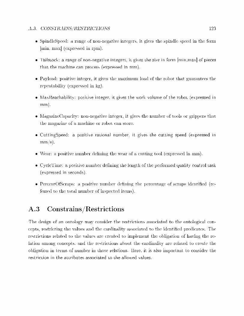
A.3. CONSTRAINS/RESTRICTIONS 123
• SpindleSpeed: a range of non-negative integers, it gives the spindle speed in the form
[min, max] (expressed in rpm).
• Tailstock: a range of non-negative integers, it gives the size in form [min,max] of pieces
that the machine can process (expressed in mm).
• Payload: positive integer, it gives the maximum load of the robot that guarantees the
repeatability (expressed in kg).
• MaxReachability: positive integer, it gives the work volume of the robot (expressed in
mm).
• MagazineCapacity: non-negative integer, it gives the number of tools or grippers that
the magazine of a machine or robot can store.
• CuttingSpeed: a positive rational number, it gives the cutting speed (expressed in
mm/s).
• Wear: a positive number de�ning the wear of a cutting tool (expressed in mm).
• CycleTime: a positive number de�ning the length of the performed quality control task
(expressed in seconds).
• PercentOfScraps: a positive number de�ning the percentage of scraps identi�ed (re-
ferred to the total number of inspected items).
A.3 Constrains/Restrictions
The design of an ontology may consider the restrictions associated to the ontological con-
cepts, restricting the values and the cardinality associated to the identi�ed predicates. The
restrictions related to the values are created to implement the obligation of having the re-
lation among concepts, and the restrictions about the cardinality are related to create the
obligation in terms of number in those relations. Here, it is also important to consider the
restriction in the attributes associated to the allowed values.
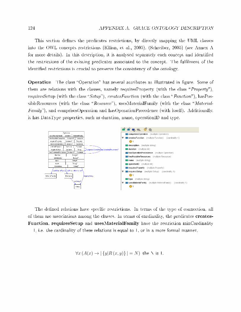
124 APPENDIX A. GRACE ONTOLOGY DESCRIPTION
This section de�nes the predicates restrictions, by directly mapping the UML classes
into the OWL concepts restrictions (Kilian, et al., 2005), (Schreiber, 2005) (see Annex A
for more details). In this description, it is analysed separately each concept and identi�ed
the restrictions of the existing predicates associated to the concept. The ful�lment of the
identi�ed restrictions is crucial to preserve the consistency of the ontology.
Operation The class �Operation� has several attributes as illustrated in �gure. Some of
them are relations with the classes, namely requiresProperty (with the class �Property�),
requiresSetup (with the class �Setup�), createsFunction (with the class �Function�), hasPos-
sibleResources (with the class �Resource�), usesMaterialFamily (with the class �Material-
Family�), and comprisesOperation and hasOperationPrecedence (with itself). Additionally,
it has DataType properties, such as duration, name, operationID and type.
The de�ned relations have speci�c restrictions. In terms of the type of connection, all
of them are associations among the classes. In terms of cardinality, the predicates creates-
Function, requiresSetup and usesMaterialFamily have the restriction minCardinality
= 1, i.e. the cardinality of these relations is equal to 1, or in a more formal manner,
∀x (A(x)→ |{y|R (x, y)} | = N) the N is 1.
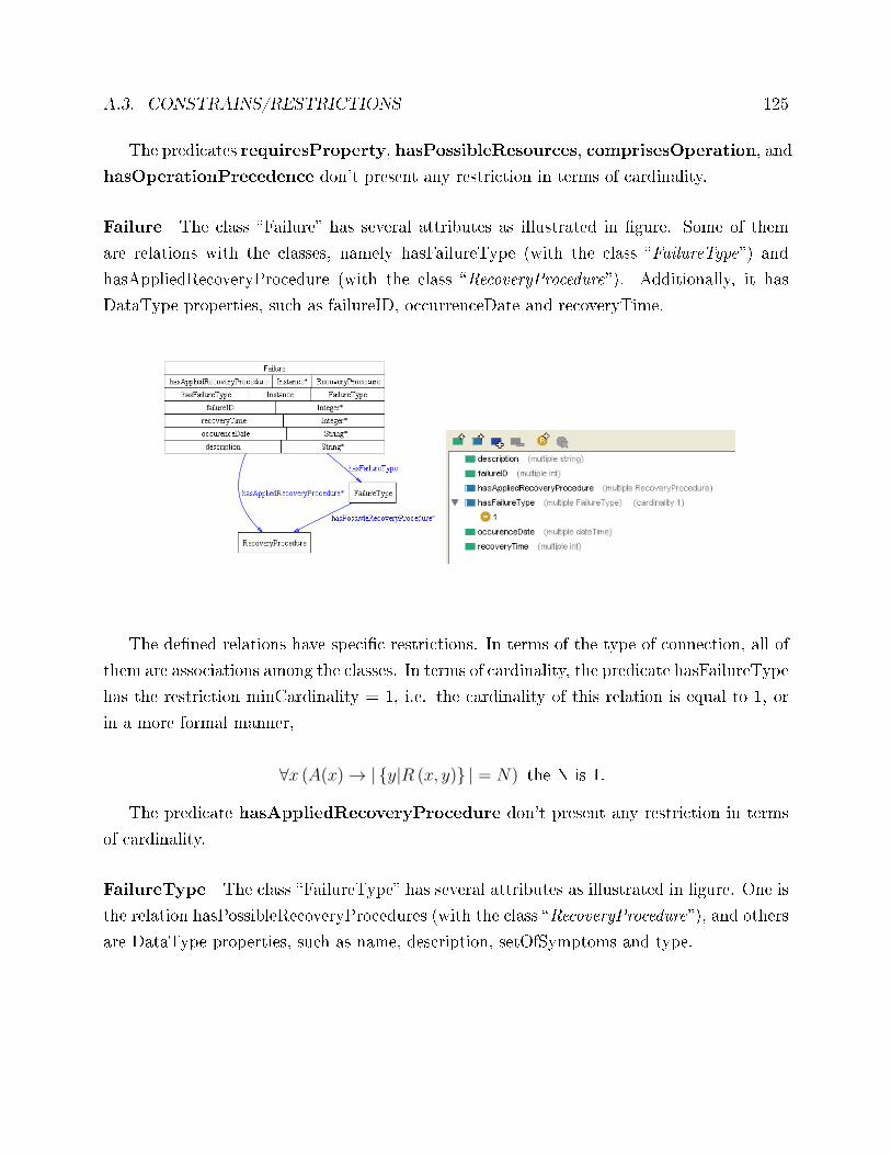
A.3. CONSTRAINS/RESTRICTIONS 125
The predicates requiresProperty, hasPossibleResources, comprisesOperation, and
hasOperationPrecedence don't present any restriction in terms of cardinality.
Failure The class �Failure� has several attributes as illustrated in �gure. Some of them
are relations with the classes, namely hasFailureType (with the class �FailureType�) and
hasAppliedRecoveryProcedure (with the class �RecoveryProcedure�). Additionally, it has
DataType properties, such as failureID, occurrenceDate and recoveryTime.
The de�ned relations have speci�c restrictions. In terms of the type of connection, all of
them are associations among the classes. In terms of cardinality, the predicate hasFailureType
has the restriction minCardinality = 1, i.e. the cardinality of this relation is equal to 1, or
in a more formal manner,
∀x (A(x)→ |{y|R (x, y)} | = N) the N is 1.
The predicate hasAppliedRecoveryProcedure don't present any restriction in terms
of cardinality.
FailureType The class �FailureType� has several attributes as illustrated in �gure. One is
the relation hasPossibleRecoveryProcedures (with the class �RecoveryProcedure�), and others
are DataType properties, such as name, description, setOfSymptoms and type.
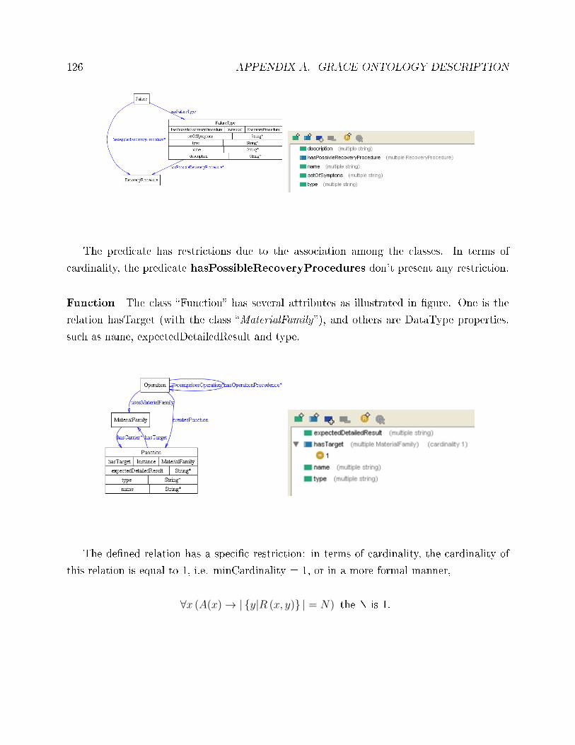
126 APPENDIX A. GRACE ONTOLOGY DESCRIPTION
The predicate has restrictions due to the association among the classes. In terms of
cardinality, the predicate hasPossibleRecoveryProcedures don't present any restriction.
Function The class �Function� has several attributes as illustrated in �gure. One is the
relation hasTarget (with the class �MaterialFamily�), and others are DataType properties,
such as name, expectedDetailedResult and type.
The de�ned relation has a speci�c restriction: in terms of cardinality, the cardinality of
this relation is equal to 1, i.e. minCardinality = 1, or in a more formal manner,
∀x (A(x)→ |{y|R (x, y)} | = N) the N is 1.
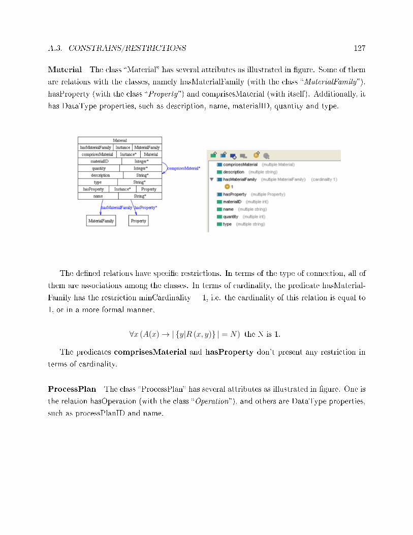
A.3. CONSTRAINS/RESTRICTIONS 127
Material The class �Material� has several attributes as illustrated in �gure. Some of them
are relations with the classes, namely hasMaterialFamily (with the class �MaterialFamily�),
hasProperty (with the class �Property�) and comprisesMaterial (with itself). Additionally, it
has DataType properties, such as description, name, materialID, quantity and type.
The de�ned relations have speci�c restrictions. In terms of the type of connection, all of
them are associations among the classes. In terms of cardinality, the predicate hasMaterial-
Family has the restriction minCardinality = 1, i.e. the cardinality of this relation is equal to
1, or in a more formal manner,
∀x (A(x)→ |{y|R (x, y)} | = N) the N is 1.
The predicates comprisesMaterial and hasProperty don't present any restriction in
terms of cardinality.
ProcessPlan The class �ProcessPlan� has several attributes as illustrated in �gure. One is
the relation hasOperation (with the class �Operation�), and others are DataType properties,
such as processPlanID and name.
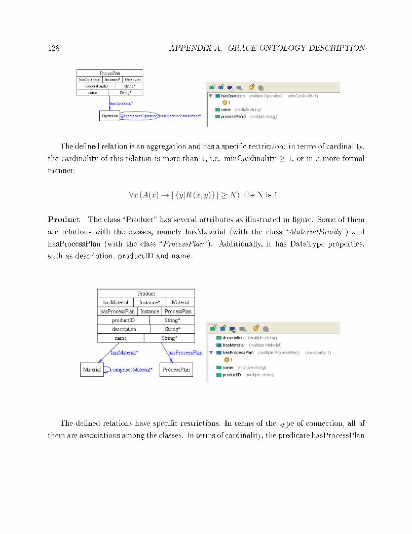
128 APPENDIX A. GRACE ONTOLOGY DESCRIPTION
The de�ned relation is an aggregation and has a speci�c restriction: in terms of cardinality,
the cardinality of this relation is more than 1, i.e. minCardinality ≥ 1, or in a more formal
manner,
∀x (A(x)→ |{y|R (x, y)} | ≥ N) the N is 1.
Product The class �Product� has several attributes as illustrated in �gure. Some of them
are relations with the classes, namely hasMaterial (with the class �MaterialFamily�) and
hasProcessPlan (with the class �ProcessPlan�). Additionally, it has DataType properties,
such as description, productID and name.
The de�ned relations have speci�c restrictions. In terms of the type of connection, all of
them are associations among the classes. In terms of cardinality, the predicate hasProcessPlan
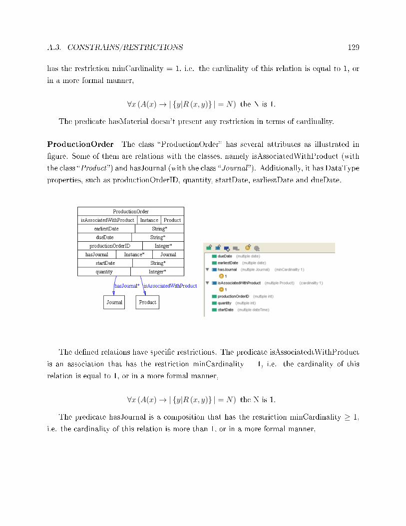
A.3. CONSTRAINS/RESTRICTIONS 129
has the restriction minCardinality = 1, i.e. the cardinality of this relation is equal to 1, or
in a more formal manner,
∀x (A(x)→ |{y|R (x, y)} | = N) the N is 1.
The predicate hasMaterial doesn't present any restriction in terms of cardinality.
ProductionOrder The class �ProductionOrder� has several attributes as illustrated in
�gure. Some of them are relations with the classes, namely isAssociatedWithProduct (with
the class �Product�) and hasJournal (with the class �Journal �). Additionally, it has DataType
properties, such as productionOrderID, quantity, startDate, earliestDate and dueDate.
The de�ned relations have speci�c restrictions. The predicate isAssociatedtWithProduct
is an association that has the restriction minCardinality = 1, i.e. the cardinality of this
relation is equal to 1, or in a more formal manner,
∀x (A(x)→ |{y|R (x, y)} | = N) the N is 1.
The predicate hasJournal is a composition that has the restriction minCardinality ≥ 1,
i.e. the cardinality of this relation is more than 1, or in a more formal manner,
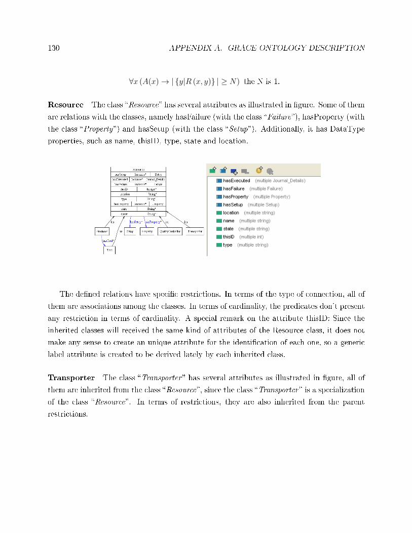
130 APPENDIX A. GRACE ONTOLOGY DESCRIPTION
∀x (A(x)→ |{y|R (x, y)} | ≥ N) the N is 1.
Resource The class �Resource� has several attributes as illustrated in �gure. Some of them
are relations with the classes, namely hasFailure (with the class �Failure�), hasProperty (with
the class �Property�) and hasSetup (with the class �Setup�). Additionally, it has DataType
properties, such as name, thisID, type, state and location.
The de�ned relations have speci�c restrictions. In terms of the type of connection, all of
them are associations among the classes. In terms of cardinality, the predicates don't present
any restriction in terms of cardinality. A special remark on the attribute thisID: Since the
inherited classes will received the same kind of attributes of the Resource class, it does not
make any sense to create an unique attribute for the identi�cation of each one, so a generic
label attribute is created to be derived lately by each inherited class.
Transporter The class �Transporter � has several attributes as illustrated in �gure, all of
them are inherited from the class �Resource�, since the class �Transporter � is a specialization
of the class �Resource�. In terms of restrictions, they are also inherited from the parent
restrictions.
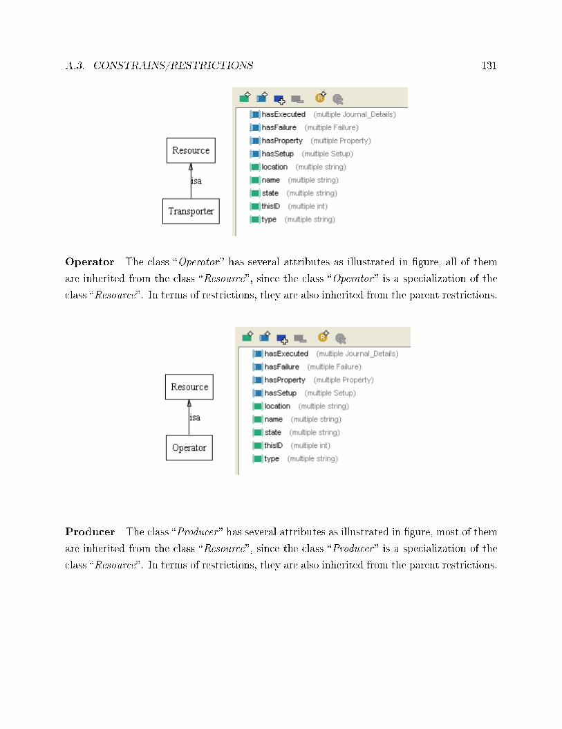
A.3. CONSTRAINS/RESTRICTIONS 131
Operator The class �Operator � has several attributes as illustrated in �gure, all of them
are inherited from the class �Resource�, since the class �Operator � is a specialization of the
class �Resource�. In terms of restrictions, they are also inherited from the parent restrictions.
Producer The class �Producer � has several attributes as illustrated in �gure, most of them
are inherited from the class �Resource�, since the class �Producer � is a specialization of the
class �Resource�. In terms of restrictions, they are also inherited from the parent restrictions.
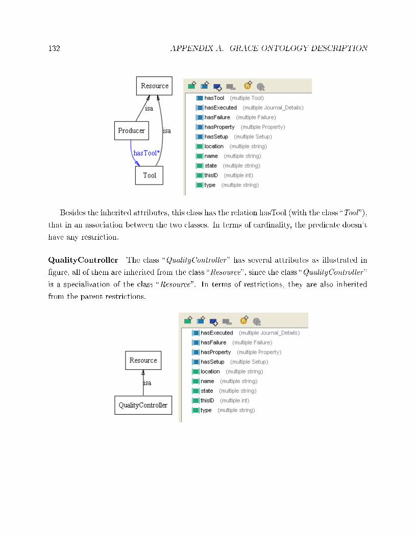
132 APPENDIX A. GRACE ONTOLOGY DESCRIPTION
Besides the inherited attributes, this class has the relation hasTool (with the class �Tool �),
that in an association between the two classes. In terms of cardinality, the predicate doesn't
have any restriction.
QualityController The class �QualityController � has several attributes as illustrated in
�gure, all of them are inherited from the class �Resource�, since the class �QualityController �
is a specialization of the class �Resource�. In terms of restrictions, they are also inherited
from the parent restrictions.
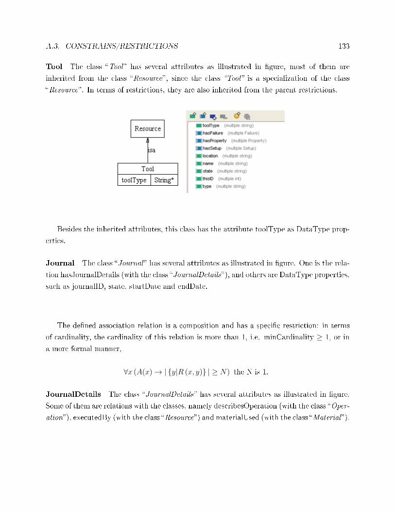
A.3. CONSTRAINS/RESTRICTIONS 133
Tool The class �Tool � has several attributes as illustrated in �gure, most of them are
inherited from the class �Resource�, since the class �Tool� is a specialization of the class
�Resource�. In terms of restrictions, they are also inherited from the parent restrictions.
Besides the inherited attributes, this class has the attribute toolType as DataType prop-
erties.
Journal The class �Journal � has several attributes as illustrated in �gure. One is the rela-
tion hasJournalDetails (with the class �JournalDetails�), and others are DataType properties,
such as journalID, state, startDate and endDate.
The de�ned association relation is a composition and has a speci�c restriction: in terms
of cardinality, the cardinality of this relation is more than 1, i.e. minCardinality ≥ 1, or in
a more formal manner,
∀x (A(x)→ |{y|R (x, y)} | ≥ N) the N is 1.
JournalDetails The class �JournalDetails� has several attributes as illustrated in �gure.
Some of them are relations with the classes, namely describesOperation (with the class �Oper-
ation�), executedBy (with the class �Resource�) and materialUsed (with the class �Material �).
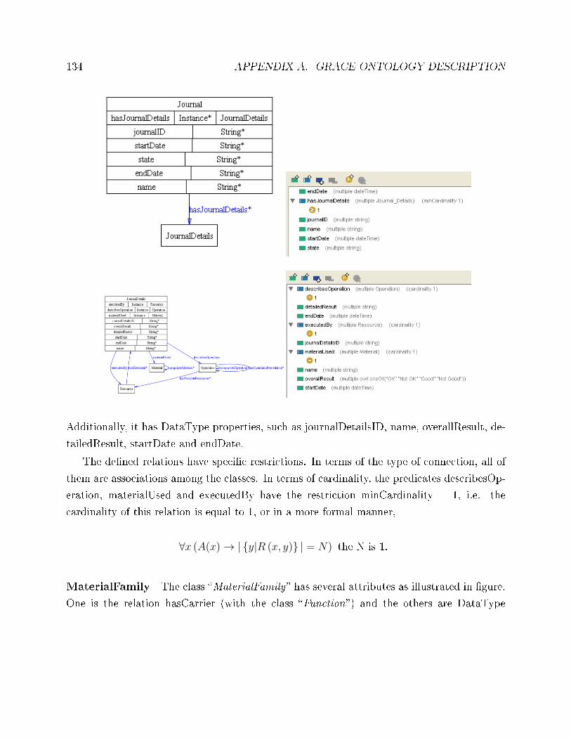
134 APPENDIX A. GRACE ONTOLOGY DESCRIPTION
Additionally, it has DataType properties, such as journalDetailsID, name, overallResult, de-
tailedResult, startDate and endDate.
The de�ned relations have speci�c restrictions. In terms of the type of connection, all of
them are associations among the classes. In terms of cardinality, the predicates describesOp-
eration, materialUsed and executedBy have the restriction minCardinality = 1, i.e. the
cardinality of this relation is equal to 1, or in a more formal manner,
∀x (A(x)→ |{y|R (x, y)} | = N) the N is 1.
MaterialFamily The class �MaterialFamily� has several attributes as illustrated in �gure.
One is the relation hasCarrier (with the class �Function�) and the others are DataType
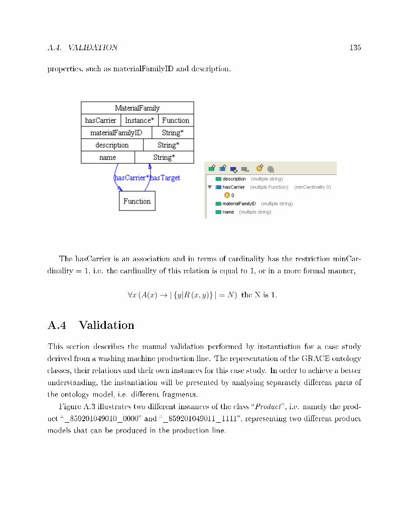
A.4. VALIDATION 135
properties, such as materialFamilyID and description.
The hasCarrier is an association and in terms of cardinality has the restriction minCar-
dinality = 1, i.e. the cardinality of this relation is equal to 1, or in a more formal manner,
∀x (A(x)→ |{y|R (x, y)} | = N) the N is 1.
A.4 Validation
This section describes the manual validation performed by instantiation for a case study
derived from a washing machine production line. The representation of the GRACE ontology
classes, their relations and their own instances for this case study. In order to achieve a better
understanding, the instantiation will be presented by analysing separately di�erent parts of
the ontology model, i.e. di�erent fragments.
Figure A.3 illustrates two di�erent instances of the class �Product�, i.e. namely the prod-
uct �_859201049010_0000� and �_859201049011_1111�, representing two di�erent product
models that can be produced in the production line.
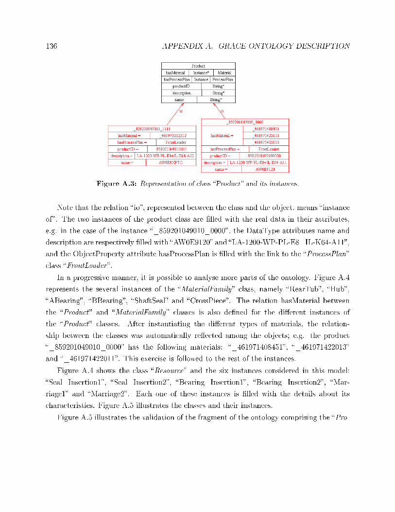
136 APPENDIX A. GRACE ONTOLOGY DESCRIPTION
Figure A.3: Representation of class �Product� and its instances.
Note that the relation �io�, represented between the class and the object, means �instance
of�. The two instances of the product class are �lled with the real data in their attributes,
e.g. in the case of the instance �_859201049010_0000�, the DataType attributes name and
description are respectively �lled with �AW0E9120� and �LA-1200-WP-PL-E8+IL-K64-A11�,
and the ObjectProperty attribute hasProcessPlan is �lled with the link to the �ProcessPlan�
class �FrontLoader �.
In a progressive manner, it is possible to analyse more parts of the ontology. Figure A.4
represents the several instances of the �MaterialFamily� class, namely �RearTub�, �Hub�,
�ABearing�, �BBearing�, �ShaftSeal� and �CrossPiece�. The relation hasMaterial between
the �Product� and �MaterialFamily� classes is also de�ned for the di�erent instances of
the �Product� classes. After instantiating the di�erent types of materials, the relation-
ship between the classes was automatically re�ected among the objects; e.g. the product
�_859201049010_0000� has the following materials: �_461971408451�, �_461971422013�
and �_461971422011�. This exercise is followed to the rest of the instances.
Figure A.4 shows the class �Resource� and the six instances considered in this model:
�Seal_Insertion1�, �Seal_Insertion2�, �Bearing_Insertion1�, �Bearing_Insertion2�, �Mar-
riage1� and �Marriage2�. Each one of these instances is �lled with the details about its
characteristics. Figure A.5 illustrates the classes and their instances.
Figure A.5 illustrates the validation of the fragment of the ontology comprising the �Pro-
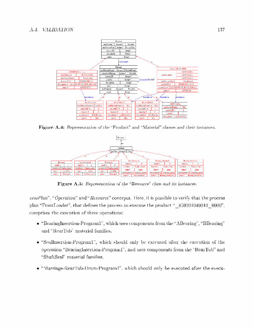
A.4. VALIDATION 137
Figure A.4: Representation of the �Product� and �Material� classes and their instances.
Figure A.5: Representation of the �Resource� class and its instances.
cessPlan�, �Operation� and �Resource� concepts. Here, it is possible to verify that the process
plan �FrontLoader�, that de�nes the process to execute the product �_859201049010_0000�,
comprises the execution of three operations:
• �BearingInsertion-Program1�, which uses components from the �ABearing�, �BBearing�
and �RearTub� material families.
• �SealInsertion-Program1�, which should only be executed after the execution of the
operation �BearingInsertion-Program1�, and uses components from the �RearTub� and
�ShaftSeal� material families.
• �Marriage-RearTub-Drum-Program1�, which should only be executed after the execu-
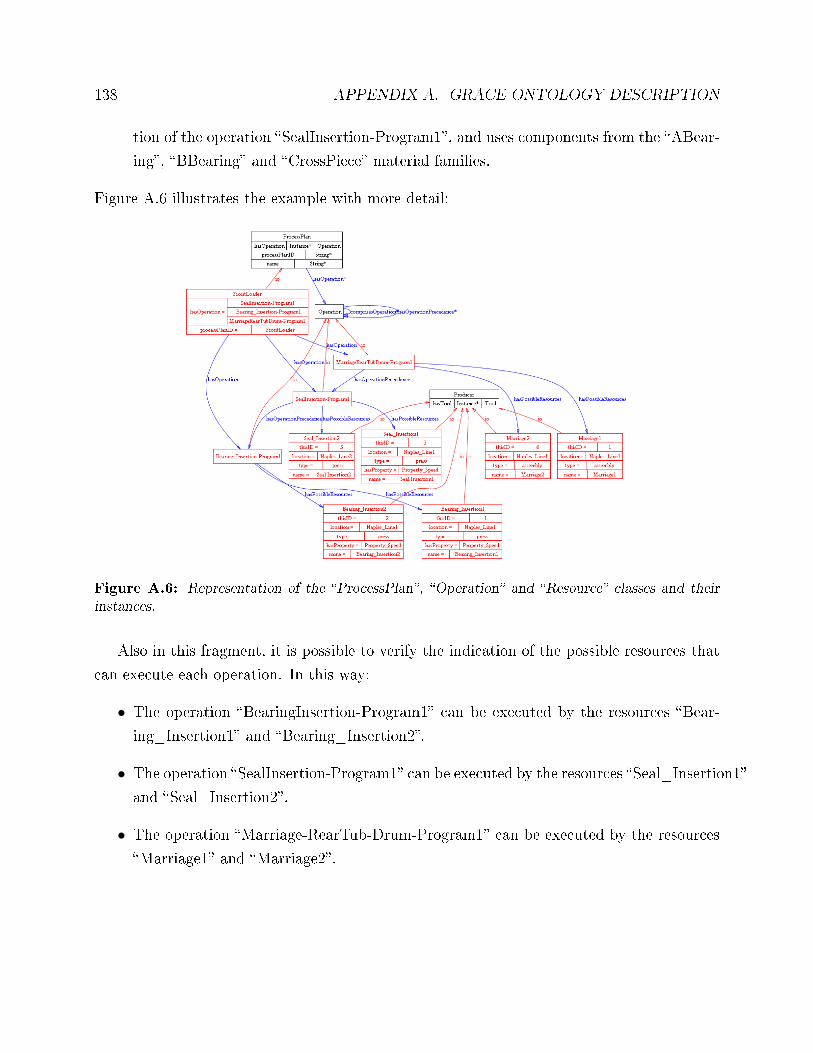
138 APPENDIX A. GRACE ONTOLOGY DESCRIPTION
tion of the operation �SealInsertion-Program1�, and uses components from the �ABear-
ing�, �BBearing� and �CrossPiece� material families.
Figure A.6 illustrates the example with more detail:
Figure A.6: Representation of the �ProcessPlan�, �Operation� and �Resource� classes and theirinstances.
Also in this fragment, it is possible to verify the indication of the possible resources that
can execute each operation. In this way:
• The operation �BearingInsertion-Program1� can be executed by the resources �Bear-
ing_Insertion1� and �Bearing_Insertion2�.
• The operation �SealInsertion-Program1� can be executed by the resources �Seal_Insertion1�
and �Seal_Insertion2�.
• The operation �Marriage-RearTub-Drum-Program1� can be executed by the resources
�Marriage1� and �Marriage2�.
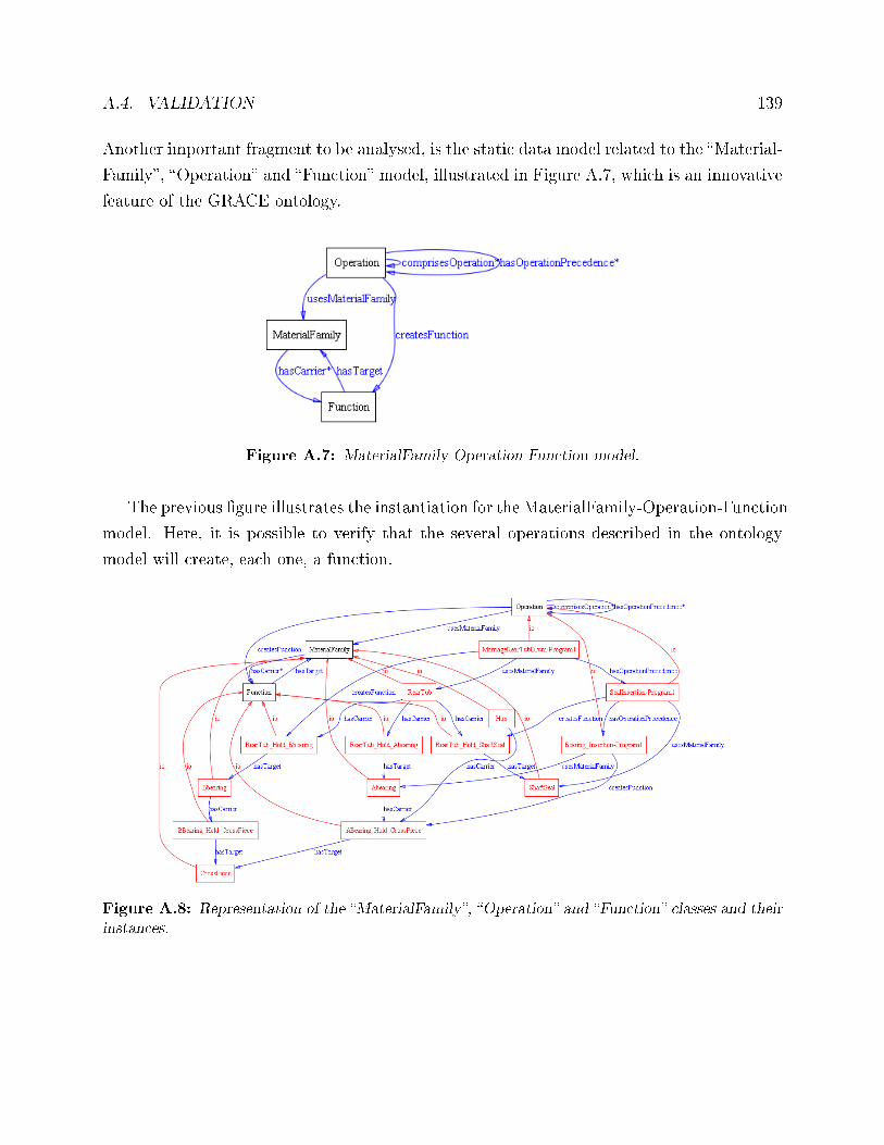
A.4. VALIDATION 139
Another important fragment to be analysed, is the static data model related to the �Material-
Family�, �Operation� and �Function� model, illustrated in Figure A.7, which is an innovative
feature of the GRACE ontology.
Figure A.7: MaterialFamily-Operation-Function model.
The previous �gure illustrates the instantiation for the MaterialFamily-Operation-Function
model. Here, it is possible to verify that the several operations described in the ontology
model will create, each one, a function.
Figure A.8: Representation of the �MaterialFamily�, �Operation� and �Function� classes and theirinstances.
140 APPENDIX A. GRACE ONTOLOGY DESCRIPTION
Examples of the functions created are the function �BBearing_Hold_CrossPiece�, �ABear-
ing_Hold_CrossPiece�, the funciton �RearTub_Hold_ABearing�, �RearTub_Hold_ BBear-
ing� and �RearTub_Hold_ ShaftSeal�.
The relations between the class �Function� and the class �MaterialFamily�, i.e. hasCar-
rier and hasTarget, allow indicating which components are involved in the operation that
creates the function, de�ned through the relation between the �Function� and �Operation�
classes. For example, the function �ABearing_Hold_CrossPiece� is completely de�ned by
the following relations:
• hasCarrier: �ABearing�
• hasTarget: �CrossPiece�
• createsFunction: �Marriage-RearTub-Drum-Program1�
Another perspective of the ontology is related to the classes that describe the dynamic pro-
duction data related to the execution of production orders in the production line, i.e. the
classes �ProductionOrder �, �Journal � and �JournalDetails�, as illustrates the Figure A.9.
Here, it is considered a production order to produce a batch of 2 items of the product
�_859201049010_0000�. The order leads to the production of the two machines described
by the instances �Journal_411142011153� and �Journal_411142011154� from the �Journal�
class. Since the production of this product model requires the execution of three operations,
as described in the process plan, each one of the instances �Journal_411142011153� and
�Journal_411142011154� has three instances of the �JournalDetails� class, related to the
description of the execution of each operation. For example, for the machine produced in the
production line and described with �Journal_411142011153�, the details are:
• �Journal_Details1�: the operation �BearingInsertion-Program1� was performed by the
resource �Bearing_Insertion1� with an overall result of OK.
• �Journal_Details2�: the operation �SealInsertion-Program1� was performed by the re-
source �Seal_Insertion1� with an overall result of OK.
• �Journal_Details3�: the operation �Marriage-RearTub-Drum-Program1� was performed
by the resource �Marriage1� with an overall result of OK.
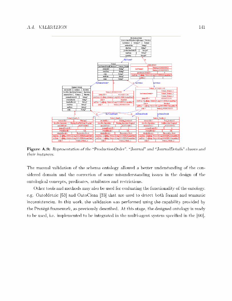
A.4. VALIDATION 141
Figure A.9: Representation of the �ProductionOrder�, �Journal� and �JournalDetails� classes andtheir instances.
The manual validation of the schema ontology allowed a better understanding of the con-
sidered domain and the correction of some misunderstanding issues in the design of the
ontological concepts, predicates, attributes and restrictions.
Other tools and methods may also be used for evaluating the functionality of the ontology,
e.g. OntoMetric [53] and OntoClean [33] that are used to detect both formal and semantic
inconsistencies. In this work, the validation was performed using the capability provided by
the Protégé framework, as previously described. At this stage, the designed ontology is ready
to be used, i.e. implemented to be integrated in the multi-agent system speci�ed in the [60].

142 APPENDIX A. GRACE ONTOLOGY DESCRIPTION
Appendix B
Frameworks to Develop Agent-based
Solutions
JADE is a Java-based architecture that uses the Java Remote Method Invocation (RMI) to
support the creation of distributed Java technology-based to Java applications. Each agent
is implemented with Java �threads� and associated with a container.
JADE aims to simplify the development of multi-agent systems by providing a set of
services and agents in compliance with the FIPA speci�cations, e.g. naming service and
yellow-page service, message transport and parsing service, and a library of FIPA interaction
protocols ready to be used [7]. Note that in the essence, the agents developed using the JADE
platform are Java Threads, which makes the debugging of multi-threading very di�cult;
consequently, some tools have been developed to simplify the development of agent-based
solutions, being every single tool provided by JADE packaged as an agent itself.
B.1 Comparison between Agent Development Platforms
After several tools have been studied, only a few were chosen. These platforms share between
them the fact of being FIPA compliance. Thus the �nal choice will be a tool that meets the
FIPA's standards.
FIPA has several platforms the most important are: FIPA-OS, Grasshopper, JACK In-
143
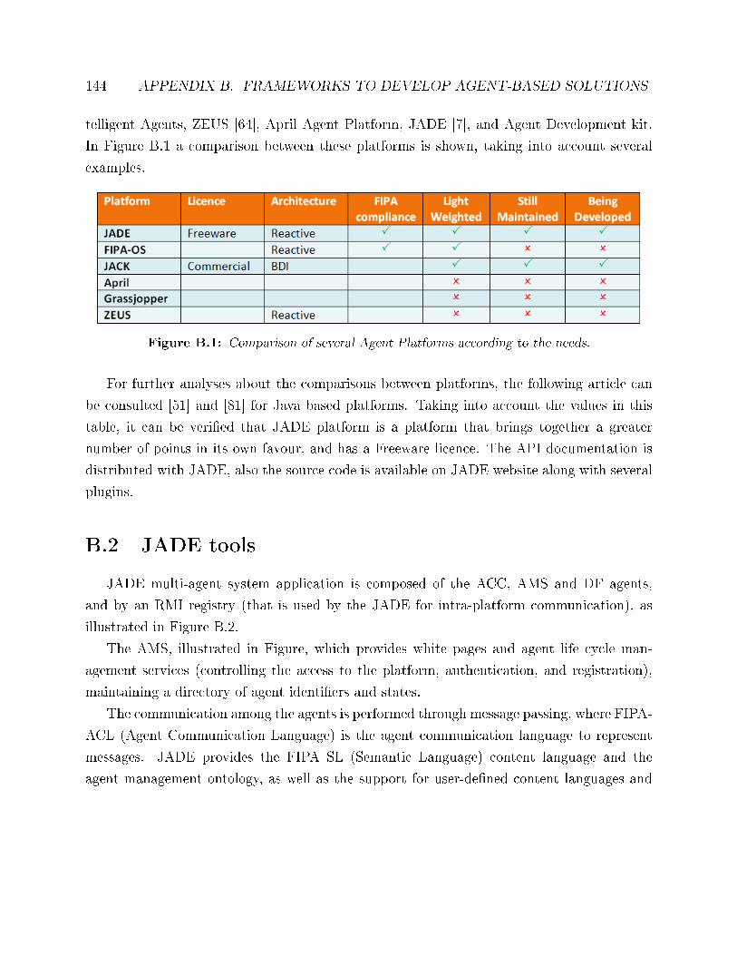
144 APPENDIX B. FRAMEWORKS TO DEVELOP AGENT-BASED SOLUTIONS
telligent Agents, ZEUS [64], April Agent Platform, JADE [7], and Agent Development kit.
In Figure B.1 a comparison between these platforms is shown, taking into account several
examples.
Figure B.1: Comparison of several Agent Platforms according to the needs.
For further analyses about the comparisons between platforms, the following article can
be consulted [51] and [81] for Java based platforms. Taking into account the values in this
table, it can be veri�ed that JADE platform is a platform that brings together a greater
number of points in its own favour, and has a Freeware licence. The API documentation is
distributed with JADE, also the source code is available on JADE website along with several
plugins.
B.2 JADE tools
JADE multi-agent system application is composed of the ACC, AMS and DF agents,
and by an RMI registry (that is used by the JADE for intra-platform communication), as
illustrated in Figure B.2.
The AMS, illustrated in Figure, which provides white pages and agent life cycle man-
agement services (controlling the access to the platform, authentication, and registration),
maintaining a directory of agent identi�ers and states.
The communication among the agents is performed through message passing, where FIPA-
ACL (Agent Communication Language) is the agent communication language to represent
messages. JADE provides the FIPA SL (Semantic Language) content language and the
agent management ontology, as well as the support for user-de�ned content languages and
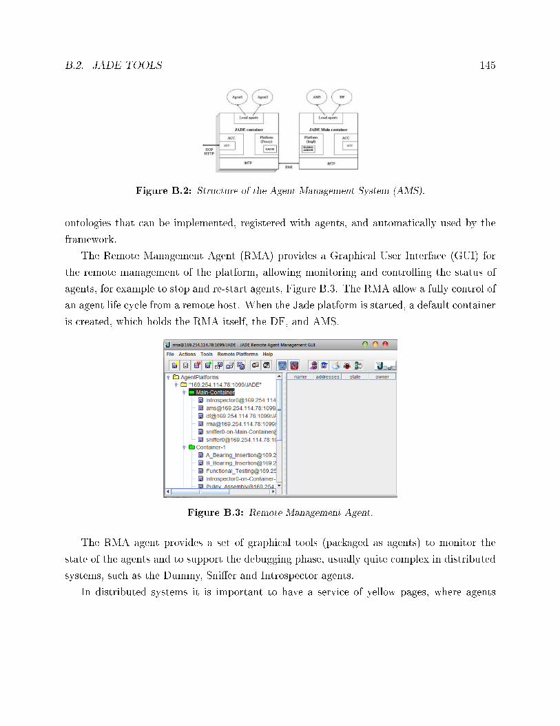
B.2. JADE TOOLS 145
Figure B.2: Structure of the Agent Management System (AMS).
ontologies that can be implemented, registered with agents, and automatically used by the
framework.
The Remote Management Agent (RMA) provides a Graphical User Interface (GUI) for
the remote management of the platform, allowing monitoring and controlling the status of
agents, for example to stop and re-start agents, Figure B.3. The RMA allow a fully control of
an agent life cycle from a remote host. When the Jade platform is started, a default container
is created, which holds the RMA itself, the DF, and AMS.
Figure B.3: Remote Management Agent.
The RMA agent provides a set of graphical tools (packaged as agents) to monitor the
state of the agents and to support the debugging phase, usually quite complex in distributed
systems, such as the Dummy, Sni�er and Introspector agents.
In distributed systems it is important to have a service of yellow pages, where agents
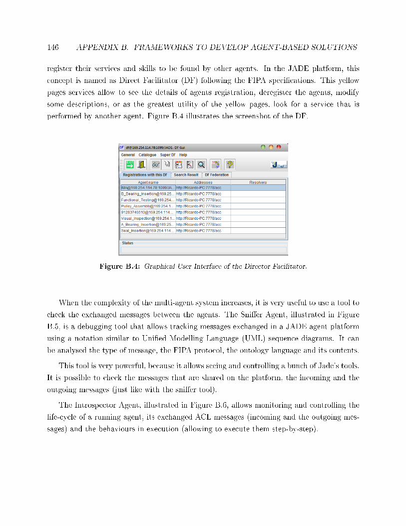
146 APPENDIX B. FRAMEWORKS TO DEVELOP AGENT-BASED SOLUTIONS
register their services and skills to be found by other agents. In the JADE platform, this
concept is named as Direct Facilitator (DF) following the FIPA speci�cations. This yellow
pages services allow to see the details of agents registration, deregister the agents, modify
some descriptions, or as the greatest utility of the yellow pages, look for a service that is
performed by another agent. Figure B.4 illustrates the screenshot of the DF.
Figure B.4: Graphical User Interface of the Director Facilitator.
When the complexity of the multi-agent system increases, it is very useful to use a tool to
check the exchanged messages between the agents. The Sni�er Agent, illustrated in Figure
B.5, is a debugging tool that allows tracking messages exchanged in a JADE agent platform
using a notation similar to Uni�ed Modelling Language (UML) sequence diagrams. It can
be analysed the type of message, the FIPA protocol, the ontology language and its contents.
This tool is very powerful, because it allows seeing and controlling a bunch of Jade's tools.
It is possible to check the messages that are shared on the platform, the incoming and the
outgoing messages (just like with the sni�er tool).
The Introspector Agent, illustrated in Figure B.6, allows monitoring and controlling the
life-cycle of a running agent, its exchanged ACL messages (incoming and the outgoing mes-
sages) and the behaviours in execution (allowing to execute them step-by-step).
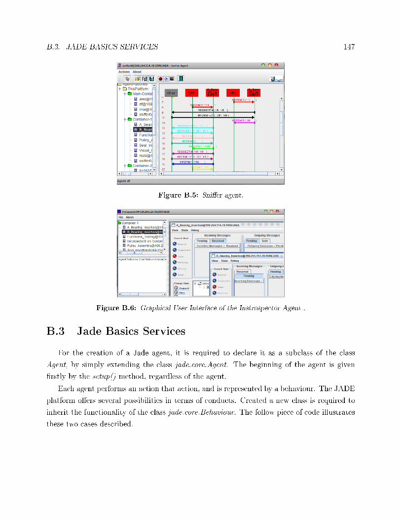
B.3. JADE BASICS SERVICES 147
Figure B.5: Sni�er agent.
Figure B.6: Graphical User Interface of the Instrospector Agent .
B.3 Jade Basics Services
For the creation of a Jade agent, it is required to declare it as a subclass of the class
Agent, by simply extending the class jade.core.Agent. The beginning of the agent is given
�rstly by the setup() method, regardless of the agent.
Each agent performs an action that action, and is represented by a behaviour. The JADE
platform o�ers several possibilities in terms of conducts. Created a new class is required to
inherit the functionality of the class jade.core.Behaviour. The follow piece of code illustrates
these two cases described.
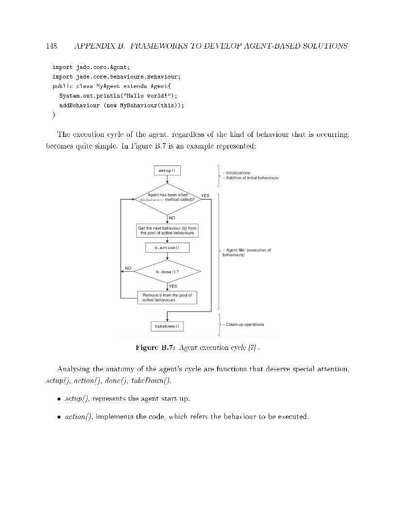
148 APPENDIX B. FRAMEWORKS TO DEVELOP AGENT-BASED SOLUTIONS
import jade.core.Agent;
import jade.core.behaviours.Behaviour;
public class MyAgent extends Agent{
System.out.println("Hello world!");
addBehaviour (new MyBehaviour(this));
}
The execution cycle of the agent, regardless of the kind of behaviour that is occurring,
becomes quite simple. In Figure B.7 is an example represented:
Figure B.7: Agent execution cycle [7] .
Analysing the anatomy of the agent's cycle are functions that deserve special attention,
setup(), action(), done(), takeDown().
• setup(), represents the agent start up.
• action(), implements the code, which refers the behaviour to be executed.
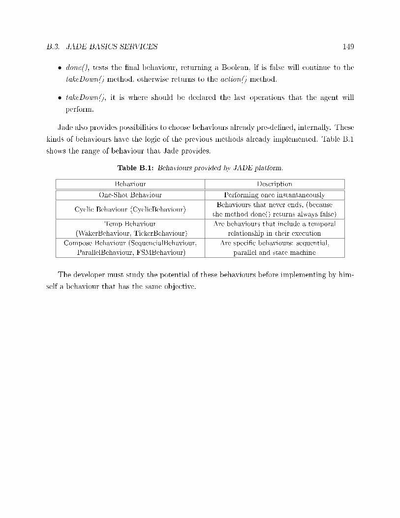
B.3. JADE BASICS SERVICES 149
• done(), tests the �nal behaviour, returning a Boolean, if is false will continue to the
takeDown() method, otherwise returns to the action() method.
• takeDown(), it is where should be declared the last operations that the agent will
perform.
Jade also provides possibilities to choose behaviours already pre-de�ned, internally. These
kinds of behaviours have the logic of the previous methods already implemented. Table B.1
shows the range of behaviour that Jade provides.
Table B.1: Behaviours provided by JADE platform.
Behaviour Description
One-Shot Behaviour Performing once instantaneously
Cyclic Behaviour (CyclicBehaviour)Behaviours that never ends, (because
the method done() returns always false)
Temp Behaviour
(WakerBehaviour, TickerBehaviour)
Are behaviours that include a temporal
relationship in their execution
Compose Behaviour (SequencialBehaviour,
ParallelBehaviour, FSMBehaviour)
Are speci�c behaviours: sequential,
parallel and state machine
The developer must study the potential of these behaviours before implementing by him-
self a behaviour that has the same objective.