Embed Size (px)
Citation preview

Pós-Graduação em Ciência da Computação
“A Web GUI for a Multi-View Component-Based
Modeling CASE Tool”
Por
Weslei Alvim de Tarso Marinho
Dissertação de Mestrado
Universidade Federal de Pernambuco
www.cin.ufpe.br/~posgraduacao
RECIFE, Agosto/2009

UNIVERSIDADE FEDERAL DE PERNAMBUCO
CENTRO DE INFORMÁTICA
Weslei Alvim de Tarso Marinho
A Web GUI for a Multi-View
Component-Based Modeling CASE Tool
ESTE TRABALHO FOI APRESENTADO À PÓS-GRADUAÇÃO EM CIÊNCIA DA
COMPUTAÇÃO DO CENTRO DE INFORMÁTICA DA UNIVERSIDADE
FEDERAL DE PERNAMBUCO COMO REQUISITO PARCIAL PARA
OBTENÇÃO DO GRAU DE MESTRE EM CIÊNCIA DA COMPUTAÇÃO.
A MASTER THESIS PRESENTED TO THE FEDERAL UNIVERSITY OF
PERNAMBUCO IN PARTIAL FULFILLMENT OF THE REQUIREMENTS FOR THE
DEGREE OF M.SC. IN COMPUTER SCIENCE.
ADVISER:
Prof. Jacques Pierre Louis Robin
RECIFE, 31 de AGOSTO de 2009

Marinho, Weslei Alvim de Tarso A Web GUI for a multi-view component-based modeling
CASE tool / Weslei Alvim de Tarso Marinho. - Recife: O Autor, 2009. xvi, 124 folhas : il., fig., tab. Dissertação (mestrado) – Universidade Federal de Pernambuco. CIn. Ciência da Computação, 2009.
Inclui bibliografia e apêndice. 1. Engenharia de software – orientada a modelos. 2. Engenharia Web. 3. Arquitetura de software. 4. KobrA . I. Título. 005.1 CDD (22. ed.) MEI2010 – 069

To my parents, who always encouraged me.

iv
AACCKKNNOOWWLLEEDDGGEEMMEENNTTSS
It is a pleasure to thank the many people who made this master thesis possible.
First I would like to thank my family for their support and belief in me.
I would like also to thank my fiancée Natália for being supportive and encouraging me.
It is difficult to overstate my gratitude to my adviser Dr. Jacques Robin for believing my
capabilities and in despite of his busy schedule, being always present with enthusiasm to
listen, explain, argue and provide guidance; without him I would be lost.
I am indebted to Breno and Fábio, who were always sharing ideas and willing to help;
without them this work would not be complete.
I wish to thank Geovane and Renata for their suggestions and very valuable feedback.
I would like also to thank all ORCAS Research Group members who were very helpful and
collaborative through many parts of this work, in special to KWAF conception and case
study execution.
I wish to thank to CIn staff for helping in many ways the conclusion of this work.
I am very grateful to CNPq for providing financial support for this work execution.
I wanted to express my gratitude for Ana Cristina and Hendrik for appraising this work.
I want to thank also all who in some way helped in this work conduction.
v
RREESSUUMMOO
Modelos oferecem abstrações de um sistema que possibilitam aos engenheiros
raciocinarem sobre o sistema se focando apenas nos aspectos relevantes, ignorando
detalhes que não são relevantes. UML se tornou um padrão de fato para análise e projeto
de sistemas, mas possui algumas limitações óbvias: (1) o conjunto de elementos é muito
heterogêneo e grande, e (2) o suporte de ferramentas não é satisfatório. Faz-se necessário
um sistema de regras que governem o processo de análise e projeto; UML é geral demais.
Desenvolvido pela UFPE em conjunto com a Universidade de Mannheim, o
objetivo do método KobrA2 é resolver essas limitações através da incorporação de visões
especiais de layout, navegação e comportamento de componentes de interface gráfica do
usuário (GUI), e pela introdução do conceito de engenharia de software ortográfica, na
qual a construção de Modelos Independentes de Plataforma (PIM) para cada componente
de software é realizado em pequenas partes através da construção ortogonal de visões
específicas para cada preocupação do componente. Estas visões são então integradas
dentro de um Modelo Unificado (SUM) que por sua vez verifica a conformidade com os
artefatos do meta-modelo de KobrA2. Para gerar ganhos de produtividade, esta integração
e verificação deve ser automaticamente implementada através da transformação de
modelos interna a uma ferramenta CASE. Consequentemente, para ter sucesso, KobrA2
precisa de uma ferramenta que dê suporte ao seu processo de engenharia de sistemas.
Esta dissertação de mestrado é parte do projeto WAKAME (Wep App KobrA2
Modeling Environment) que tem por objetivo a construção desta ferramenta CASE. Além
de ser a primeira ferramenta CASE dirigida por processo e que dá suporte a um ambiente
OO, ortográfico, dirigido por modelos e baseado em componentes, para engenharia de
aplicações, incluindo a construção de GUI PIMs, WAKAME também procura inovar por
ser (a) distribuída em uma plataforma de cloud computing e acessível universalmente
através de qualquer navegador Web, (b) ser de muito fácil aprendizagem graças a sua GUI
minimalista, com poucos ícones, no estilo do Google, e (c) de uso eficiente graças ao seu
cliente projetado para ser leve e com pouco uso de memória e que forneça um esquema de

vi
navegação multidimensional, ortográfico e independente de plataforma, entre visões de
baixa granularidade, específica a preocupações, e locais, de um componente.
Dentro do projeto WAKAME, esta dissertação de mestrado investiga três principais
questões em aberto. A primeira é o projeto de KWAF (KobrA2 Web App Framework), um
modelo independente de plataformas de um ambiente OO genérico para ser instanciado
para projetos específicos de aplicações Web. A segunda é o PIM detalhado de WAKAME
como um exemplo de instanciação de KWAF. A terceira é a implementação e avaliação de
componentes de GUI, cobrindo (a) as visões estruturais de componentes KobrA2 que
minimamente estendem um subconjunto mínimo de diagramas de classes UML e restrições
estruturais de OCL, e (b) as visões operacionais de componentes KobrA2 que consistem de
precondições, pós-condições e restrições body de OCL sobre operações UML.
As principais contribuições desta dissertação são: (a) o projeto de KWAF, o
primeiro estudo de caso para avaliação do processo KobrA2 para aplicações Web ricas
com gráficos 2D, (b) o projeto de alto nível do WAKAME como estudo de caso para
avaliação de KWAF, (c) a implementação de um cliente Web fácil de usar e eficiente para
o projeto ortográfico de PIMs de composição de componentes KobrA2, e (d) a integração e
teste deste cliente GUI com os serviços baseados em nuvem computacional de WAKAME
para integração, verificação e persistência de visões PIM dentro do SUM.
Palavras-chave: Engenharia de software dirigida por modelos, Engenharia Web,
Ferramentas CASE, KobrA2

vii
AABBSSTTRRAACCTT
Models offer abstractions of a system that allows engineers to reason about that system
while ignoring details that are not relevant to focus on the most relevant aspects. The
Unified Modeling Language (UML) has become a de facto standard for system analysis
and design but, in fact, UML has some obvious shortcomings: (1) the set of result types is
too large and heterogeneous, leading the user to ambiguous interpretation, and (2) its tool
support is not satisfactory. It is necessary a system of rules which governs the analysis and
design process, UML is too general.
Developed jointly by Universität Mannheim and UFPE, the KobrA2 method aims
to addresses these weaknesses by incorporating special views to model the layout,
navigation and behavior of GUI components and introducing the concept of orthographic
software engineering in which building a Platform-Independent Model (PIM) for each
software component is piecemealy carried out by constructing largely orthogonal concern-
specific views of the component. These views are then integrated into a Single Unified
Model (SUM) which is in turn verified for conformance to the KobrA2 artifact metamodel.
To bring productivity gains, this integration and verification must be automatically
implemented by model transformations built in a CASE tool. Therefore, to be successful
KobrA2 needs a tool that gives support to its system engineering process.
This Master's Thesis is part of the WAKAME (Web App KobrA Modeling
Environment) project that aims at constructing such CASE tool. In addition to be the first
CASE tool to be process-driven and to support orthographic, model-driven, component-
based OO framework and application engineering, including GUI PIM construction,
WAKAME also aims to innovate by being (a) deployed on a cloud computing platform
and accessible ubiquitously through any web browser, (b) being very easy to learn thanks
to a minimalist, few icons, few actions, Google-style GUI and (c) efficient to use thanks to
a thin client, lightweight design and a multi-dimensional navigation scheme among
cognitively fine-grained, concern-specific, local, orthographic component PIM views.
Within the WAKAME project, this Master's Thesis investigates three main open questions.
The first is the design of KWAF (KobrA Web App Framework), a platform-independent

viii
model of a generic OO framework to be instantiated to design specific web applications.
The second is the detailed PIM of WAKAME as an example instantiation of KWAF. The
third is the implementation and evaluation of GUI components covering (a) the structural
KobrA2 component views that minimally extend a minimal subset of UML class diagrams
and OCL structural constraints and (b) the operational KobrA2 component views that
consist of OCL precondition, post-condition and bodies on UML operations.
The main contribution of the thesis are: (a) the design of KWAF, the first case
study to validate the KobrA2 method for rich web applications with 2D graphics, (b) the
high-level design of WAKAME as a case study validating KWAF, (c) the implementation
of an easy to use, efficient GUI web client for orthographic design of component assembly
KobrA2 PIMs, and (d) the integration and testing of this GUI client with WAKAME's
cloud-based services for PIM view integration into a SUM, SUM verification, SUM
persistence and view persistence.
Keywords: Model driven software engineering, Web engineering, CASE Tools, KobrA2

ix
CCOONNTTEENNTTSS Chapter 1. Introduction .................................................................................................. 1
1.1. Context and Motivation ..................................................................................................... 1
1.2. Research Goals ................................................................................................................... 7
1.3. Research Methodology ...................................................................................................... 8
1.4. Master Thesis Structure ..................................................................................................... 9
Chapter 2. Software Engineering Background ............................................................... 11
2.1. Model-Driven Engineering ............................................................................................... 11 2.1.1 MDE Goals, Principles and Vision ............................................................................... 11 2.1.2 Precise Modeling and Metamodeling with OCL2.0 .................................................... 14
2.2. Component-Based MDE ................................................................................................... 14 2.2.1 Component-Based Software Engineering .................................................................. 14 2.2.2 The KobrA1 CBMDE Method ...................................................................................... 15 2.2.3 The KobrA2 CBMDE Method ...................................................................................... 20
2.3. GUI Engineering ................................................................................................................ 26 2.3.1 GUI Engineering Issues ............................................................................................... 27 2.3.2 The Authoring Process of the UML-based Web Engineering Approach .................... 28 2.3.3 A UML Profile for GUI Layout ..................................................................................... 29 2.3.4 A UML Profile for GUI Development .......................................................................... 30 2.3.5 Graphical User Interface Platform Independent Model UML2.0 Framework ........... 31
2.4. UML CASE Tools ............................................................................................................... 33 2.4.1 UML CASE Tools Analysis ........................................................................................... 35
2.5. Chapter Remarks .............................................................................................................. 39
Chapter 3. WAKAME Project ......................................................................................... 41
3.1. Long-Term Goals and Principles ....................................................................................... 41
3.2. KWAF ................................................................................................................................ 42 3.2.1 KWAF Framework: Principles, Structure and Case Study........................................... 43 3.2.2 Structural models of the KWAF Component .............................................................. 44 3.2.3 Structural Models of the Webservice Component .................................................... 45 3.2.4 Structural Models of GUIClient Component .............................................................. 50 3.2.5 KWAF Assessment Remarks ....................................................................................... 53
3.3. WAKAME Top-Level PIM .................................................................................................. 54 3.3.1 WAKAME as an Instance of KWAF ............................................................................. 55 3.3.2 The WAKAME Component ......................................................................................... 56
3.4. Chapter Remarks .............................................................................................................. 59
Chapter 4. The WAKAME GUI ....................................................................................... 60
4.1. The WAKAMEGUI Development Process ......................................................................... 60

x
4.2. The KWAF instance Platform Independent Model for the WAKAME GUI Project ........... 61 4.2.1 The WAKAMEGUIClient Component .......................................................................... 61 4.2.2 The WAKAMEMVCView Component ......................................................................... 63 4.2.3 The WAKAMEGUIController Component ................................................................... 73 4.2.4 Issues Raised during WAKAME GUI Platform Independent Model ........................... 79
4.3. The WAKAME GUI Implementation and Unit Testing ...................................................... 81
4.4. The WAKAME GUI Integration, Integration Testing and System Testing ......................... 87
4.5. The WAKAME Publishing .................................................................................................. 90
4.6. Chapter Remarks .............................................................................................................. 96
Chapter 5. Assessment Experiments with Early Adopters ............................................... 97
5.1. Experiment Definition ...................................................................................................... 97
5.2. Execution and Analysis of the Case Study ...................................................................... 101
5.3. Experiment Findings ....................................................................................................... 110
5.4. Chapter Remarks ............................................................................................................ 111
Chapter 6. Conclusion ................................................................................................. 112
6.1. Contributions .................................................................................................................. 112
6.2. WAKAME GUI Limitations .............................................................................................. 113
6.3. Future Work on WAKAME GUI ....................................................................................... 113
6.4. Limitations of the WAKAME as a Whole ........................................................................ 113
6.5. Future Work on WAKAME as a Whole ........................................................................... 114
6.6. Concluding Remarks ....................................................................................................... 114
Chapter 7. References ................................................................................................. 115
Appendix A Survey: WAKAME Evaluation ......................................................................... 120

xi
LLIISSTT OOFF FFIIGGUURREESS Figure 1-1 - Orthographic modeling in architecture .......................................................................... 4
Figure 1-2 - Transformation engines reflecting changes of one element in different views ............. 5
Figure 2-1. Typical MDE Transformation scheme ........................................................................... 13
Figure 2-2 - Locality Principle of KobrA ............................................................................................ 17
Figure 2-3. Komponent Structure. ................................................................................................... 19
Figure 2-4 - Multiple Views with SUM. ............................................................................................ 21
Figure 2-5 – KobrA2 Views ............................................................................................................... 23
Figure 2-6 - Prototypical Structural Class Service View.................................................................... 23
Figure 2-7 - Prototypical Structural Class Type View ....................................................................... 24
Figure 2-8 - Prototypical Specification Operational Service View .................................................... 25
Figure 2-9 - Papyrus UML screenshot .............................................................................................. 36
Figure 2-10 - Together ...................................................................................................................... 37
Figure 2-11 - Rational Software Modeler ......................................................................................... 38
Figure 2-12 - MagicDraw .................................................................................................................. 39
Figure 3-1 - The Web Application Photo Album............................................................................... 44
Figure 3-2 - Structural Model of the KWAF Component .................................................................. 45
Figure 3-3 - The WebService Component with its sub-components: Service Controller, MVCAction and MVCModel ................................................................................................................................ 46
Figure 3-4 - Platform Independent Model of the of the Photo Album application WebService Component ....................................................................................................................................... 46
Figure 3-5 - Platform Specific Model of the Photo Album application WebService component..... 47
Figure 3-6 - The MVCModel Component Structure ......................................................................... 49
Figure 3-7 - Entities and data types for the MVCModel component, representing the Model in MVC .................................................................................................................................................. 50
Figure 3-8 - GUIClient component structure .................................................................................... 50
Figure 3-9- PhotoAlbum GUI Navigation Model .............................................................................. 51
Figure 3-10 - PhotoView Component Structural Model .................................................................. 52
Figure 3-11 - GUIController Component Structural Model .............................................................. 52
Figure 3-12 - PhotoAlbumGUIController Component and the Definition of one Action using OCL 53
Figure 3-13 - WAKAME Top-Level .................................................................................................... 55
Figure 3-14 – KWAF component structure. ...................................................................................... 55
Figure 3-15 - WAKAME Specification Structural Class Service View ................................................ 56

xii
Figure 3-16 - WAKAME Realization Structural Class Service View ................................................... 57
Figure 3-17 - WAKAME Realization Structural Class Type View ....................................................... 57
Figure 4-1 - The WAKAMEGUIClient Component Specification ....................................................... 62
Figure 4-2 - The WAKAMEGUIClient Component Realization .......................................................... 63
Figure 4-3 - The WAKAMEMVCView Component Specification....................................................... 64
Figure 4-4 - WAKAMEMVCView navigation model (1 of 3).............................................................. 65
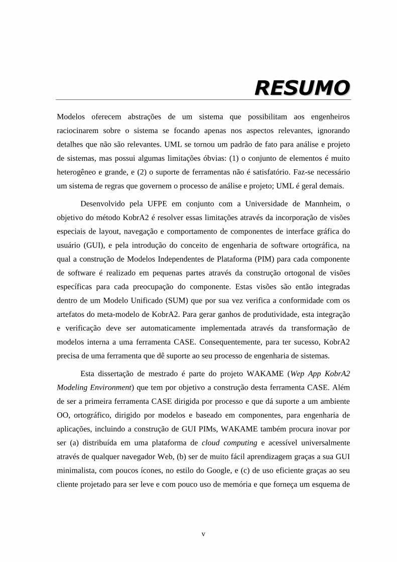
Figure 4-5 - WAKAMEMVCView navigation model (2 of 3).............................................................. 66
Figure 4-6 - WAKAMEMVCView navigation model (3 of 3).............................................................. 66
Figure 4-7 - The WAKAMEHome Window Layout ............................................................................ 67
Figure 4-8 - The CreateNewModel Window Layout ......................................................................... 68
Figure 4-9 - The ChooseModel Window Layout ............................................................................... 68
Figure 4-10 - The ViewEditModel Window Layout .......................................................................... 69
Figure 4-11 - The ActionResult Window Layout ............................................................................... 69
Figure 4-12 - The ImportModel Window Layout.............................................................................. 70
Figure 4-13 - The WAKAMEMainWindow Layout ............................................................................ 71
Figure 4-14 - The EditorFrame Layout .............................................................................................. 72
Figure 4-15 - The DiagramFrame Layout .......................................................................................... 72
Figure 4-16 - The WAKAMEGUIController Component Specification .............................................. 73
Figure 4-17 - The WAKAMEGUIController Component Realization ................................................. 74
Figure 4-18 - The WAKAMEGUIController Realization Types .......................................................... 74
Figure 4-19 - The ViewSelectionHandler’s actionPerformed() operation contract ......................... 75
Figure 4-20 - The ViewPersistenceHandler’s actionPerformed() operation contract ..................... 75
Figure 4-21 - The fromCloud() operation contract ........................................................................... 76
Figure 4-22 - The toCloud() operation contract ............................................................................... 76
Figure 4-23 - The updateGUI() operation contract .......................................................................... 77
Figure 4-24 - The ViewVolatilityHandler's actionPerformed() operation contract .......................... 78
Figure 4-25 - The MenuHandler's actionPeformed() operation contract ........................................ 78
Figure 4-26 - The link between KobrA and DI's metamodels ........................................................... 79
Figure 4-27 - The link between the Element class from the Views package to the GUIPIMUF Graphic class ..................................................................................................................................... 80
Figure 4-28 - Debug messages in the WAKAME Main Window ....................................................... 86
Figure 4-29 - Register issue Window in the WAKAME issue tracker ................................................ 89
Figure 4-30 - Issues list at the WAKAME issue tracker ..................................................................... 89
Figure 4-31 - The WAKAME tool Home Window ............................................................................. 90
Figure 4-32 - The WAKAME tool ChooseModel Window ................................................................. 91
Figure 4-33 - The WAKAME tool ViewEditModel Window .............................................................. 91

xiii
Figure 4-34 - The WAKAME tool ActionResult Window ................................................................... 92
Figure 4-35 - The WAKAME tool ImportModel Window .................................................................. 92
Figure 4-36 - The WAKAME tool CreateModel Window .................................................................. 93
Figure 4-37 - The WAKAME Main Window ...................................................................................... 93
Figure 4-38 - Editing a Specification Structural Type view in WAKAME tool .................................. 94
Figure 4-39 - Editing a Realization Structural Class Service view in the WAKAME tool ................... 94
Figure 4-40 - Manipulation of an operational view in the WAKAME tool ....................................... 95
Figure 4-41 - Warning Message in the WAKAME tool Main Window .............................................. 95
Figure 5-1 - Educational Level of Participants ................................................................................ 102
Figure 5-2 - Familiarity of the Participants with the RSM and WAKAME tools. ............................. 102
Figure 5-3 – Model Completeness Comparison. ............................................................................ 103
Figure 5-4 –Availability Related Answers Comparison................................................................... 104
Figure 5-5 - Performance Related Answers Comparison. .............................................................. 105
Figure 5-6 - Ease of Use Related Answers Comparison. ................................................................ 108
Figure 5-7 - Diagram Layout Control and Legibility Related Answers Comparison. ...................... 109
Figure 5-8 - Standard Compliance Related Answers Comparison.................................................. 110

xiv
LLIISSTT OOFF TTAABBLLEESS Table 4.1 - WAKAMEGUIClient source code metrics ....................................................................... 87
Table 5.1 - Familiarity of Participants with the Tools RSM and WAKAME. .................................... 104
Table 5.2 – Assessment Summary .................................................................................................. 111

xv
LLIISSTT OOFF AACCRROONNYYMMSS
API – Application Programming Interface
CASE – Computer Aided Software Engineering
CBD – Component Based Development
CBE – Component Based Engineering
CIM – Computer Independent Model
CPU – Central Processing Unit
DI – Diagram Interchange
DHTML – Dynamic HTML
DSL – Domain-specific language
EJB – Enterprise Java Beans
GAE – Google App Engine
GEF – Graphical Editing Framework
GUI – Graphical User Interface
GUIPIMUF – Graphical User Interface Platform Independent Model UML2.0 Framework
HCI – Human Computer Interaction
HTML – HyperText Markup Language
HTTP – HyperText Transfer Protocol
IDE – Integrated Development Environment
JAR – Java Archive
KWAF – KobrA Web App Framework
MARTE – Modeling and Analysis of Real-Time and Embedded Systems
MDA – Model Driven Architecture
MDD – Model Driven Development

xvi
MDE – Model Driven Engineering
MOF – Meta Object Facility
MT – Model Transformation
MVC – Model View Controller
OCL – Object Constraint Language
OMG – Object Management Group
OO – Object Oriented
ORCAS – Ontologies and Reasoning Components for Agents and Simulations
PIM – Platform Independent Model
PSM – Platform Specific Model
RAM – Random Access Memory
RSM – IBM Rational Software Modeler
SVG – Scalable Vector Graphics
SysML – Systems Modeling Language
SUM – Single Unified Model
UI – User Interface
UML – Unified Modeling Language
URL – Universal Resource Locator
WAKAME – Web App KobrA Model Engineering
WYSIWYG – What You See Is What You Get
XML – Extensible Markup Language
XMI – XML Metadata Interchange

1
CCHHAAPPTTEERR 11..
IINNTTRROODDUUCCTTIIOONN
In this chapter we present the context on which this work is present, the motivation for this
work, its goals, the used methodology and its structure.
1.1. Context and Motivation
There are two mainstream software development methodologies: the agile methodologies,
where are predominant the SCRUM and XP and the traditional, also known as heavy
weighted, methodologies whose main player is the Rational Unified Process.
SCRUM and XP brings many good ideas, what have made their acceptance widely
spread. XP is based in a set of principles and practices where we can highlight: pair artifact
construction, iterative requirement test and construction after only partial requirement
elicitation and before requirement implementation, focus on artifacts that directly lead to
running code and continuous integration to tested running prototype. SCRUM by being a
more management methodology brings as strengths: informal, collective task allocation
and time estimates and focus on creating team spirit and maintaining motivation. The agile
methodologies also have a common application scope comprising small stable teams of
developers with solid experience with application type and domain, implementation
platform(s) and all software engineering roles and continuous access to known, committed
users. However, despite its strengths and wide application scope, SCRUM and XP present
a common limitation: a) lack of practices and guidelines for software reuse, b) deployment
platform fragmentation and rapid changes, c) team turnover, d) team geographical
scattering, e) rookies, f) innovative applications with no experienced developers nor even
know users and, g) high-level architectural design of large, complex software and product
lines
On the other hand, the Rational Unified Process representing the traditional
methodologies presents as strengths: project decomposition in phases largely orthogonal to
process steps, Computer Aided Software Engineering (CASE) tool assisted construction of

2
digitally stored, abstract requirement, architecture and design models, prior to coding, use
of visual, standard notation for these models (Unified Modeling Language - UML) and is
customizable. The Rational Unified Process has as application scope large, distributed,
heterogeneous development team changing over long lifecycle. However, it presents the
following limitations: a) lack of practices and guidelines for software reuse, b) for each
artifact which part of the huge UML2 meta-model to use, c) generate code from behavioral
models, and d) building testing models.
The Model Driven Engineering (MDE) searches to overcome the limitations
present in both: agile and traditional methodologies. As goals, MDE has as goals: separate
business analysis and design refinement from platform-specific coding, build a Platform-
Independent Model (PIM) refined enough to serve as input to full code generators,
including behavioral code, switch focus away from manual writing and testing application-
specific and platform-specific code and towards developing reusable application-
independent code (i.e., model to code transformations) and PIMs and transform models
from mere abstract documentation to concrete executable specifications. Model Driven
Architecture (MDA), the main figure of the MDE methodologies, reuses integrated
consolidated comprehensive self-extensible standard modeling language family such as
Metamodel Object Facility (MOF2), Object Constraint Language (OCL2), Unified
Modeling Language (UML2) and Diagram Interchange (DI).
MDE has as application scope applications for domains with platform
heterogeneity, fragmentation and rapid evolution (e.g., mobile and desktop clients, cloud
servers). Despite its attempt to overcome existing weaknesses, MDE also present
limitations: a) it is mere engineering philosophy, no being consolidated nor widely adopted
specific methods yet, and b) it offers no practice or guidelines for: reusing functionalities
across applications or define for each artifact which part of the huge UML2 meta-model to
use.
By relying in a set of standards, MDE opposes to Domain Specific Modeling
Languages (DSML) which focuses on creating specific language families for each
particular domain. A domain-specific language (DSL), whether used for model-driven
engineering (MDE) is a piece of critical infrastructure that is developed during the system
engineering process: DSLs show an increased correspondence of languages constructs to
domain concepts when contrasted with general purpose languages. As a result, a DSL will
more accurately represent domain practices and will more accurately support domain

3
analysis (Kolovos et al, 2006). On the other hand, the Unified Modeling Language (UML)
has become a de facto standard for system analysis and design but, in fact, UML has some
obvious shortcomings: (1) the set of result types is too large and heterogeneous, leading the
user to ambiguous interpretation, and (2) tool support is not satisfactory to DSLs - It is
necessary a system of rules which governs the analysis and design process, UML is too
general.
In addition, UML is not really a practical modeling language; it is more a modeling
language tool-kit that tries to offer many different ways of modeling may different aspects
of many different software projects. Because of the redundancy, general-purpose, gigantic
size of the UML plus the lack of support from UML tools to customize the interaction
experience with the users, some developers adopts the user of a UML profile, not so much
to extend UML, but also to restrict UML, that is to say to select few constructs and
diagrams relevant for the application domain and system engineering process. Other
developers use domain specific languages renouncing all together to UML, and yet others
does not use modeling practices, renouncing all together to Platform Independent Models
(PIM).
The problems present in MDE and UML directed the research efforts of Atkinson
in a German project developed at Fraunhofer-Gesellschaft Institute in Experimental
Software Engineering (IESE), Kaiserlautern, Germany what aimed to create a new method,
named KobrA. The KobrA method was published in the book "Component-based product
line engineering in UML" and it had one extension with component test modeling through
European Research Project Component++, 2000-2003, having participation from industry
and academy in ten countries (Atkinson et al., 2001). This experience was published in one
second book "Component-based software testing with UML" (Gross, 2004). The KobrA
method had as goals: a) integrate MDE with Component-Based Development (CBD) and
Product Line Engineering (PLE), b) focus on engineering PIMs for reuse and with reuse
and c) precisely prescribe what artifacts and sub-artifacts to build at each process step,
together with constraints that must hold among them. However a large part of the KobrA
artifacts was still in natural language, what hardens the model transformations work and
can lead to ambiguity. This was the main limitation of the KobrA method.
Developed jointly by Universität Mannheim and UFPE, the KobrA2 method aims
to address KobrA weaknesses by substituting the informal mix of UML1.4 diagrams, ad-
hoc table and natural language of KobrA1 models by semi-formal, natural language free,

4
UML2 diagrams plus OCL2 expressions. KobrA2 leads to build a PIM: a) which method
constraint conformance can be checked automatically and b) from which full code,
including behavioral code, can be automatically generated by application-independent
model to code transformations.
Another important aspect of KobrA2 is the support to orthographic software
engineering, a concept originated in the architecture where the architect does not build a
complex 3D model encompassing all aspects of a building. Instead, it creates a model
representing the front of the house, another with the top view and so on, as shown in
Figure 1-1.
Figure 1-1 - Orthographic modeling in architecture
When we apply the same orthographic principle in modeling software, the software
engineer can focus on one specific aspect of the problem while ignoring less relevant
aspects, such as detailed feature design while worried about the overall architecture. As a
consequence different representations of the same element exist in different models, what
brings the need of keep all representations in harmony. This is done through a
transformation engine which reflects changes across models. KobrA2 is based in this
principle, where views represent each aspect of a particular element, stored in a Single
Unified Model (SUM). Views comprising models of one SUM element and a
transformation engine are shown in Figure 1-2.

5
Figure 1-2 - Transformation engines reflecting changes of one element in different views
Summarizing, KobrA2 is a model-driven, component-based, product line
engineering method that is not direct competitor, but rather complementary to mainstream
software development methods, such as agile and traditional. It provide reuse-oriented,
technical design practices and guidelines that fill gaps in these methods. One could for
example: use RUP practices for project phase decomposition and planning, use SCRUM
practices for people management, task allocation and resource estimates, use KobrA2
practices for modeling a reusable PIM and use XP practices for implementing the PIM and
testing the implementation.
As the use of models and transformations in KobrA2 requires constant validation
and verification of models and elements consistency, a CASE (Computer Aided Software
Engineering) tool is needed for support its use. A KobrA2 CASE tool states as its
requirements:
1. To be driven by KobrA2 method
2. Provide visual edition of UML2 constructs and diagrams reused in KobrA2 views
3. Offer a component containment tree navigation to pick «subject» component of
view

6
4. Present a simple (one click) navigation among concern-specific views of «subject»
component
5. Perform automatic verification of view meta-model conformance with informative
message pinpointing violation causes
6. Offer automatic integration of views into a SUM
7. Provide automatic verification of resulting SUM meta-model conformance with
informative message able to pinpoint violation causes in view elements
8. Perform automatic projection of SUM into selected views
9. Provide OCL2 expression textual edition with:
a. Syntax highlight
b. Syntax checking with informative message pinpointing error location
c. Expression auto-complete in the context of a KobrA2 SUM
However, after analysis of the CASE tool market, there was found no CASE tool
that could:
Support orthographic software engineering distinguishing between SUM and views
Support modeling applications with UML2 meta-model extension and constraints
defined using the same tool
Provide helpful OCL2 syntax error messages
Support process instantiation into project plan, project plan monitoring and control
Magic Draw, sole UML2 CASE tool to support all constructs and diagrams reused
in KobrA2 views does not support OCL2 syntax highlight, checking and auto-complete.
All commercial UML2 CASE tools analyzed:
Are diagram-driven instead of process (method) driven and/or component-driven
Are desktop-deployed and very difficult to install
Require prohibitive local computing resources (RAM, CPU) to run efficiently
Are far too expensive for most software development organizations, especially in
emergent economies

7
Suffer from feature and window overkill and too indirect inter-window
navigability making them too hard to learn and too slow to use, discouraging MDE
adoption
All UML2 CASE tools available as web apps and freeware desktop apps analyzed
support edition of only very limited subset of UML2 constructs and diagrams and do not
support OCL2 expression edition. As a consequence KobrA2 can hardly be used within
current tools due to their limitations, and when it could be used it impacted greatly in
productivity. This was our motivation for developing this work.
1.2. Research Goals
Based on the motivation described in Section 1.1, we defined the WAKAME Project,
where WAKAME stands for Web App KobrA2 Model Engineering, whose goal is to
develop, evaluate and research issues regarding an integrated set of CASE tools to assist
effective model driven engineering institutionalization. Thus, the project aims toward a
web CASE tool, named also WAKAME, which supports the creation of models described
in the KobrA2 method. This project initially comprises the work of two Masters Students,
being this master thesis the result of part of the project. Hence, the project scope is divided
into:
Research, development and evaluation of the WAKAME Server, part of the
WAKAME tool. The WAKAME Server is a repository of KobrA2 models,
comprising components for: processing the model, maintain consistency among
elements present in different views, transform models across views to allow different
representations of the same subject, importing and exporting models to XMI and
integration with the GUI component; and
Research, development and evaluation of the WAKAME GUI, a thin client for the
WAKAME tool, which is the scope of this master thesis. This WAKAME Client will
enable the user to interact with the tool for the creation and manipulation of KobrA2
models. This client will also be integrated with the server, and serve as a base for
model manipulation from the user‘s perspective.
The goal of the work described in this master thesis is the development and
evaluation of the component WAKAME GUI Client of the WAKAME tool, which allows:
(a) manipulation of KobrA2 components orthographic views, (b) verify compliance within

8
the view, according to the KobrA2 Metamodel constraints, and (c) communicate with the
WAKAME Server for views persistence.
The specific goals of the research and development work described in this master
thesis are defined bellow:
Develop and evaluate a Platform Independent Model (PIM) framework to simplify
Web applications modeling. Without a framework for set the architectural and design
base, there is much work involved in redefining this structural and behavioral
foundation every time a new application needs to be created. Another issue is based
on the fact that model driven engineering concerns about model transformation, thus
a different set of transformations needs to be specified for generate platform specific
models for each new Web application. By providing a common environment the
framework would reduce time-to-market of Web applications development
addressing the common structure definition rework and transformations reuse. This
framework is named KobrA2 Web App Framework (KWAF);
Create the high level WAKAME tool PIM, as a KWAF instance. This would also
define the communication between the components of GUI Client and WAKAME
Server. This work is concerned specifically with the tool GUI platform independent
model, which was implemented and evaluated;
Publish the WAKAME tool to the KobrA2 community, what represents one of the
main contributions of this research and development work.
1.3. Research Methodology
The research methodology of this work is the Action Research (Thiollent, 1986; Kock,
2007), which has an empirical base that is designed and carried out in close association
with an action or a solution to collective problem. In the Action Research the researchers
and participants of the situation or problem are involved in cooperative or participatory
mode.
The Action Research includes methods that fit into the concept of doing a research
and applying it on development, that is, research for the action (Rodrigues, 2004). Here
lays the methodology used in this work, because we do a technology research to solve a
particular problem that is the lack of an integrated CASE tool to assist Model Driven

9
Engineering practice through the application of KobrA2 method, and then, we use the
researched results to solve it.
Based on this methodology it was defined three main phases for this work: (1)
gathering of information on subjects related to our problem comprising the lack of
integrated CASE tool, (2) the development of the tool which would solve the problem, and
(3) perform of a case study to assess the tool performance.
The first phase focused on defining the goals for the project and executing pragmatic
studies on related technologies and standards related to MDE, cloud computing and
CASE tools.
The second phase aimed to define an architecture for platform-independent models
(PIM) for Web applications and validate it through a case study (the PIM of an Web
PhotoAlbum), develop the PIM for the WAKAME GUI, implement the components
according to the defined PIM, integrate the GUI with the WAKAME Server and
finally perform verification through the use of both integration and system testing.
This work was structured this way because we practice what we preach with the
MDE and KobrA2 usage.
In the third and final phase, an experiment was conducted to evaluate the tool, where
the experiment participants were asked to perform a modeling session using the
WAKAME tool, and do the same in another MDE CASE tool, the IBM Rational
Software Modeler (RSM). The IBM RSM tool was used because it was the industry
standard for which we had license. The modeling session comprised a KobrA2
method class, a KWAF class, and two modeling sessions: one in WAKAME and
other in RSM. This study provided to us real results and thus measures of the
feasibility of WAKAME usage and the WAKAME tool‘s quality in terms of
performance, usability and modeling productivity.
1.4. Master Thesis Structure
This master thesis comprises this introductory chapter and six more chapters. In Chapter 2
is presented the methodological background for this research which comprises Model
Driven Engineering, Component Based Engineering, the KobrA2 method, GUI
Engineering and the UML CASE tools analyzed. Chapter 3 presents the WAKAME
project, with its principles and goals, exhibiting also the KobrA Web App Framework

10
developed in this work, its assessment with a case study, and the high level PIM for the
WAKAME tool. In Chapter 4 it is presented the WAKAME GUI models, its
implementation, integration and testing with the WAKAME Server, as well as the
WAKAME tool publishing. Chapter 5 describes the assessment experiment performed to
evaluate the WAKAME tool and its data interpretation. Finally, Chapter 6 presents the
contributions of this work, WAKAME tool limitations and future work as well as the
conclusions obtained. Chapter 7 shows the used references. Furthermore, also is part of this
master thesis the Appendix A, which contains the survey used in the case study.

11
CCHHAAPPTTEERR 22..
SSOOFFTTWWAARREE
EENNGGIINNEEEERRIINNGG
BBAACCKKGGRROOUUNNDD
In this chapter we describe the key technologies of software engineering we use to develop
the components of our proposed application. In particular, we present the ideas of model-
driven engineering and component-based development, a set of principles and technologies
that provide the structural basis of this thesis.
2.1. Model-Driven Engineering
Model-Driven Engineering (MDE) was put forward by the Object Management Group, a
consortium of large companies and academic centers, under the initiative known as Model-
Driven Architecture (MDA). MDE proposes essentially to raise the level of abstraction
where most of the development effort is spent from source code to models, metamodels
and model transformations.
2.1.1 MDE Goals, Principles and Vision
The fundamental long-term vision of MDE is that systems may be specified and realized in
a completely refined way in a so called platform independent model (PIM). Then this PIM
is translated to platform-specific models, which in turn are translated to source code either
manually or by model transformations. The MDE initiative expects several benefits from
this shift. Among them are: platform-independent business model reuse, increasing
productivity and increasing deployment speed, easier applications maintenance and as a
consequence of all three, economic gains in the software life-cycle as a whole.
Model-Driven Engineering pursues two related goals. The first is to minimize the
cost of deploying the same functionalities on a variety of platforms, i.e. modeling once and
having it deployed many times in different computational environments such as web

12
services, EJB, .NET etc. The second goal is to automate an ever growing part of the
development process required during the life cycle of an application.
To achieve these goals, MDE switches the software engineering focus away from
low-level source code towards high-level models, metamodels (i.e., models of modeling
languages) and Model Transformations (MT) that automatically map one kind of model
into another. MDE prescribes the construction of a fully refined Platform Independent
Model (PIM) together with at least two sets of MT rules to translate the PIM into source
code via an intermediate Platform Specific Model (PSM).
In MDE, development starts by constructing a precise model of the application
domain, which in MDE terminology is called a Computational Independent Model
(CIM). This first artifact defines the common, more abstract entities of the business
domain in question, allowing the engineers to understand the big picture in which the
future software system will be placed. The CIM must also be described using UML
artifacts (such as Use-cases, statechart diagrams etc) but must not include any information
about the application realization nor its behavior. A CIM should come fully equipped with
traceability links to its further refinements in order to provide (semi) automated translation
to the next refined artifacts.
A CIM generates a Platform Independent Model (PIM) of the application. This
PIM should be a refinement of the software design down to the level of instructions
available as built-in by the most widely used platform for a particular domain (e.g., Open
GL or Direct3D methods for computer graphics, EJB or .Net for web information systems).
It constitutes the most strategic, persistent, reusable asset of the MDE process.
To ease the automation of such translating task, MDE proposes to divide it in two
stages: first from the PIM to a Platform Specific Model (PSM) and then from such PSM
to source code. The PSM is still a hybrid visual and textual notation but it incorporates
concepts that are specific to one target implementation platform. The modeling languages
used for the PIM and PSM must be formalized by a metamodel. The translations from PIM
to PSM can then be specified as transformation rules from a source metamodel pattern to a
corresponding target metamodel pattern. Pattern matching is then used to generate the
PSM from the PIM and the code from the PSM.
Nowadays, a MDE CIM, PIM and PSM can be fully specified using the UML2
standard (OMG, 2009) for it incorporates (a) a platform independent component

13
metamodel, (b) the high level OO functional constraint language OCL2 (OMG, 2009) to
fully detail, constraint and query UML2 models, and (c) the Profile mechanism to define,
in UML2 itself, UML2 extensions with platform specific constructs for diverse PSM. MT
for PIM to PIM and PIM to PSM to code translation can be specified using the rule-based,
hybrid declarative-procedural Atlas Transformation Language (ATL) (ATL, 2009).
2.1.1.1. Automated Model Transformations
In MDE, the generation of deployment artifacts and ultimately a running application is
obtained through incremental translation of these models (e.g. PIM to PSM, PSM to code).
These translations are encoded as model transformations, which establish the traceability
links from abstract models down to the platform-specific deployment level.
A transformation takes as input a source model accompanied with its metamodel
(i.e. its specification) and generates a target model again according to a given metamodel
(typically target and source metamodels are different, but not necessarily). Figure 2-1
shows this general transformation scheme. In MDE, a typical transformation pipeline
would take as input a platform-independent model (and associated metamodel) and
generate some PSM, according to a corresponding target metamodel. From the PSM
another transformation in the pipeline would generate the final source code.
Figure 2-1. Typical MDE Transformation scheme
A transformation tool must obviously contain a way to express a description of how
a model should be transformed, i.e. a transformation specification. In general, a
transformation consists of a collection of transformation rules, which are unambiguous
specifications of the way that the objects of the source model can be used to create the
objects of the target model. A transformation is expressed at metamodel level; in fact a
transformation expresses the structural mappings between the source metamodel and the
target metamodel. They are however applied and executed on the input models, not the
input metamodel to produce the output model (again not the output metamodel).

14
2.1.2 Precise Modeling and Metamodeling with OCL2.0
The Object Constraint Language (OCL) is a semi-formal specification with a hybrid
functional object-oriented syntax. It is used to define constraints and queries over UML
models and MOF metamodels. OCL expressions can be used to specify invariants over
classes, pre- and pos-conditions over operations execution, derived attributes of a class and
finally side-effect free operations as queries over a model. UML modelers can use OCL to
specify:
Arbitrary complex structural constraints among potentially distant elements of an
application UML structural diagram or language metamodel; for this purpose OCL
has the expressive power of first-order logic, and allows specifying class invariants
and derived attributes and associations;
Arbitrary complex algorithms that combine behavior of class operations or message
passing; for this purpose is Turing-complete and allows specifying operations
preconditions read-only operation bodies and read-write operations post-conditions.
2.2. Component-Based MDE
A Component-Based MDE process (Atkinson et al, 2001) structures the PIM, PSM and
source code as assemblies of reusable components, each one clearly separating the services
interfaces that it provides to and requires from other components from its encapsulated
realization of these services (itself potentially a recursive sub-assembly).
2.2.1 Component-Based Software Engineering
While Model-driven Development fosters reuse of application models across platforms,
CBD fosters reuse of functionalities across applications. A software component
encapsulates a set of basic functionalities whose need recurs in diverse applications. It
contains metadata that specifies how to assemble these functionalities with those
encapsulated in other components to build more complex functionalities through assembly.
According to (Eriksson et al, 2003) ―a component is a self-contained unit that
encapsulates the state and behavior of a set of classifiers‖. All the contents of the
components, including its sub-components, are private. A component is always associated
to provided and required interfaces. The key feature of CBD is the ability to promote the
reuse of software components. The full encapsulation and separation of interface from

15
implementation enables a component to be a substitutable unit that can be replaced at
design time or run time by another component that offers equivalent functionality.
In an assembly, a given component may act as both a server to some component
and a client to another component. The assembly structural meta-data of a component
includes provided interfaces, the operations (together with their input and output parameter
types) that are available by connecting to the server ports of the component. It may also
include required interfaces, the operations (together with their input and output parameter
types) that the component expects to be available in the deployment environment through
connections to its client ports. A component may also include assembly behavioral meta-
data that describes the pre- and post-conditions of the operations provided and required at
its ports in terms of its states and the states of its clients and servers in the assembly. Such
meta-data allows defining a contract between a client-server component pair. Such design
by contract permits black-box reuse, which is ideal for leveraging third party software and
more cost-effective than the white-box reuse by inheritance in object-oriented frameworks.
A component can be substituted at any time by another one that is internally different but
respect the same contracts at its ports, without affecting the rest of the software.
2.2.2 The KobrA1 CBMDE Method
The KobrA method recently integrated Component-based development, MDE and product-
line engineering, together with standard techniques such as top-down refinement and
object-oriented development, in a coherent and comprehensive whole. It is a significant
breakthrough in CBMDE because:
It promotes reuse over the entire range of development stages, from requirement to
modeling, implementation, testing, quality insurance and maintenance;
In contrast to previous methods, it provides precise guidelines for most software
engineering aspects, including a finely grained recursive process, the artifacts to
specify at each step, well-formed rules for each of these artifacts as well as for the
relations between them and quality metrics and control;

16
It is fully platform and tool independent by relying on the UML standard as to
specify all the software artifacts1.
A fundamental feature of KobrA is the distinction between products (software
artifacts) and processes (software engineering tasks). A KobrA project defines the products
independently from the processes that might be applied. Many methods mix up the
description of what to do with how to do it. This makes difficult to decide what is
absolutely necessary to perform and what is optional. This distinction has recently been
adopted as an OMG standard in the Software Process Engineering Metamodel 2.0 (SPEM).
Other important concerns that KobrA distinguishes are the organization of the
method in terms of three orthogonal dimensions: the first dealing with the level of
abstraction; the second dealing with the level of genericity; and the third dealing with the
level of composition. In a typical KobrA project development begins with a generic,
abstract, black-box description of the system. To create an application from this first black-
box it is necessary to: i) remove the genericity of the black-box (instantiation), ii)
decompose the black-box into smaller parts (decomposition) and iii) reduce the level of
abstraction to create an executable version of the system (embodiment).
In KobrA all three dimensions can be dealt with separately. The genericity
dimension is tackled by the product line engineering approach; the composition dimension
comes under the umbrella of component modeling, and development concerning the
abstraction dimension comes under the component embodiment activity. These concerns
can be tackled in various orders, and even arbitrarily interwoven (Atkinson et al, 2001).
A central goal of KobrA is to enable the full expressive power of the UML to be
used in the modeling of components. To this end the use of the UML in KobrA is driven
by four basic principles:
Uniformity: Every behavior-rich entity is treated as a Component, and every
Component is treated uniformly, regardless of its granularity or location in the containment
tree. In particular, the system as a whole is viewed and modeled as a Component, albeit a
1 Except for code that is beyond the scope of the UML and for which KobrA puts forward the ―Normal
Object Format‖, an abstract language that integrates the semantically common constructs of C++, Java and
C# while abstracting from their syntactic differences.

17
large-grained one. This endows a Component containment tree (and the applications
created from them) with the property of a fractal, since the products (and the
accompanying processes) are identical at all levels of granularity. It also promotes reuse,
because any Component, anywhere in a containment tree, can be made into a system if it
satisfies the needs of some customer.
Encapsulation: The description of what a software unit does is separated from the
description of how it does it. Encapsulating and hiding the details of how a unit works
facilitates a ―divide and conquer‖ approach in which a software unit can be developed
independently from its users. This allows new versions of a unit to be interchanged with
old versions provided that they do the same thing.
Locality: All descriptive artifacts represent the properties of a Component from a
local perspective rather than a global perspective. This means that there are no diagrams, or
other descriptive artifacts, that take a global perspective and cover all aspects of the
system. Even the largest Component at the root of the containment tree only has a black-
box view of its sub-Components, and thus its models only describe its local properties. By
reducing the coupling between components this promotes reuse. Figure 2-2 illustrates this
principle.
Figure 2-2 - Locality Principle of KobrA
Parsimony: Every descriptive artifact should have "just enough" information, no
more and no less. This means that all models and diagrams should contain the minimum

18
amount of information needed to describe the necessary properties, but no more. Including
more model elements than necessary simply obscures the essential information, and
complicates the models.
In the most abstract level, KobrA prescribes a software product-line approach. A
framework as defined by the methodology is a set of generic artifacts that might create
several similar applications. There is a decision model associated with each artifact in
order to indicate how to instantiate the framework into a specific application. This
information is gathered together in the context realization, which is the initial analysis and
modeling of the environment in which the systems it is to execute. The KobrA context
realization produces the same artifacts as the realization of Komponents we describe
below.
The intermediate level of granularity of KobrA is the component-based paradigm.
Applications are organized in terms of hierarchical composition of reusable KobrA logical
components (usually referred as Komponent). Each Komponent is built using the same
artifacts in a recursive fashion. At development time a containment tree that composes
recursively Komponents and sub-Komponents until the most basic component level
represents a system.
A Komponent is modeled in terms of a specification, which describes what kind of
services the Komponent provides for other Komponents that might be associated to it
through a client-sever or ownership relation, hence a Komponent specification is a
description of the requirements that the Komponent is expected to fulfill.
A Komponent may also have one realization associated to its specification, which
describes precisely how a Komponent implements its specification (partly with the help of
server Komponents).
Figure 2-3 illustrates the two views of a Komponent.

19
Figure 2-3. Komponent Structure.
2.2.2.1. Strenghts
1. Only comprehensive full life cycle reused oriented software method.
2. Follow a few simple principles and apply them uniformly.
3. Thorough separation of concerns by integrating MDE with CDB and PLE.
4. Fully prescriptive for the UML artifact to produce at each step of the process.
5. Detailed guidelines on how to produce those artifacts.
2.2.2.2. Weaknesses
1. Based on UML 1.4, tables and natural language which prevents the most advanced
model-transformation based flavor of MDE.
2. Says nothing specifically for GUI modeling.
3. PLE approach presupposes that framework model contains all artifacts of all possible
product instantiation, which is unpractical in many real cases.
4. Focuses on PIM modeling, saying very little on PIM to PSM and PSM to code
translation tasks.
5. Not modeled explicitly in SPEM.
6. No capability and maturity model to adopt it incrementally, which is a very serious
practical barrier due to its artifact heavy nature and incorporation of three cutting
edge reuse oriented techniques that are not yet wide spread.
7. Focuses on software engineering for reuse, saying very little about software
engineering with reuse of legacy software.

20
8. Last but not least, has a very limited set of case studies that can serve as models for
software engineering teams.
Except for the last one, most of these weaknesses are shared by most other software
engineering methods.
2.2.3 The KobrA2 CBMDE Method
A second version of the KobrA method is currently being developed by the ORCAS Group
(CIn – UFPE) with the Fakultät für Mathematik und Informatik, Universität Mannheim
(FMI-UM), in Mannheim, Germany. KobrA2 expect to accommodate new trends such as
support for more advanced forms of MDE and Component Based Engineering (CBE):
By leveraging the latest OMG standards: UML 2.1 modular metamodel and better
founded profiles; UML 2.1 full life cycle components; OCL 2.0 to model PIM, PSM,
metamodels and UML 2.0 profiles that are fully refined and free of natural language
ambiguities, thus viable input to fully automatic model transformation; MOF 2.0
(MOF, 2006) and Ecore (Ecore, 2009) to define the KobrA2 metamodel; and
By leveraging model transformation to weave product-specific elements onto
framework components instead of or in addition to instantiating them, and to add on
and take off Built-In Contract Testing (BICT).
The Specification and Realization views in KobrA2 are described via a metamodel
that reuses and extends a minimal, consolidated, UML2 core, restricting model elements
and enforcing consistency between views via OCL expressions. A comprehensive
technical report about KobrA2 is in (Atkinson et al, 2009).
The KobrA2 method integrates three software reuse approaches: Model-Driven
Engineering (MDE), Component-Based Development (CBD) and Object-Oriented (OO)
frameworks. Beyond this integration, KobrA2 also innovates in two other ways. First it
incorporates special views to model the layout, navigation and behavior of GUI
components. Second, it introduces the concept of orthographic software engineering in
which building a Platform-Independent Model (PIM) for each software component is
piecemeal carried out by constructing largely orthogonal concern-specific views of the
component. These views are then integrated into a Single Unified Model (SUM) which is
in turn verified for conformance to the KobrA2 artifact metamodel.

21
2.2.3.1. KobrA2 Principles
The main principles of the KobrA2 method are:
Separation of Concerns - Separates functionalities of whole software concerns into
reusable components. For each component separate: (a) PIM from PSM from code; (b)
general product line framework model from specific product application model; (c)
execution model from testing model; (d) specification from private, encapsulated
realization; (e) structural model from behavioral model from operational model; (f)
computational service aspects from data structures aspects; (g) concept (class) from
instance (object) model.
Multiple Views – for each component, provide one view for each point in the multi-
dimensional space of separated concerns and reconcile these views into a Single Unified
Model (SUM). The Figure 2-4 shows the relationship between the SUM and the views.
Figure 2-4 - Multiple Views with SUM.
Prescriptiveness – KobrA2 strives to precisely prescribe, as much as possible for a
general purpose software engineering method, which UML2 and OCL2 model elements as
basis to the development of each view of a KobrA component.
Formally Specified Rules to Automatically Conformance Checking – KobrA2
defines rules to check the conformance of the model in the following levels: (a) view-level;
(b) component-level; and (c) assembly-level.
Parsimony – avoid as much as possible redundant model elements and views. To do
this, KobrA2 choose a minimum model elements and diagram subsets of UML2, able to
cover the key aspects/concerns of a software component.

22
Locality – all KobrA2 Views are local to a given component, and this component
has the stereotype <<subject>> to specify the component owner of the View. The whole
PIM of the system is derivable from the union of all these local views.
Uniformity – the sole first-class modeling entity deserving to possess its own
multiple views is the KobrA2 component. All behaviorally complex entities are modeled
as a KobrA2 component, including the system itself, and only behaviorally trivial system
entities are modeled as KobrA2 classes.
Top-down Decomposition – the realization of any KobrA2 component K potentially
consist of an assembly of finer-grained components, encapsulated in K and not directly
visible outside of K.
2.2.3.2. KobrA2 Views
KobrA2 defines sixteen Views which can be seen in Figure 2-5 and that are described
below.
Specification Structural Class Service View – specifies the local assembly
connections of the subject component class, and its interface. Allow only public
operations and attributes. A prototypical Specificatin Structural Class Service View
can be seen in Figure 2-6.
Specification Structural Class Type View – defines the non-primitive data types used
by the subject component class in the Specification Structural Class Service View.
The operations and attributes need to be public. A prototypical Specification
Structural Cass Type View is shown in Figure 2-7.

23
Figure 2-5 – KobrA2 Views
Figure 2-6 - Prototypical Structural Class Service View

24
Specification Structural Instance Service View – defines typical instantiation patterns
of the Specification Structural Class Service View of the subject component class. It
allows ComponentObjects with public slots, and Acquires and Creates associations.
Figure 2-7 - Prototypical Structural Class Type View
Specification Structural Instance Type View – defines typical instantiation patterns of
the Specification Structural Class Type View of the subject component class. It
allows ComponentObjects with public slots, and Acquires and Creates associations.
Specification Operational Service View - declaratively specifies the behavioral
contracts between the component classes of the Specification Structural Class
Service View of the subject component class. It shows the OCL precondition, post-
condition or body constraints of the operations. A prototypical Specification
Operational Service View is shown in Figure 2-8.
Specification Operational Type View - declaratively specifies the behavioral
contracts between the component classes, (data) classes and association classes of the
Specification Structural Type View of the subject component class. It shows the OCL
precondition, post-condition or bodies constraints of the operations.

25
Figure 2-8 - Prototypical Specification Operational Service View
Specification Behavioral Protocol View - defines the external visible state transitions
of the subject component class together with the restricted subset of its public
operation that is available for invocation in each of these states. Contains a simple
UML2 protocol state machine. The sequence of operations on the state machine
transitions represent the protocol to follow to satisfy the invocation contract of the
services provided by the subject component class.
Realization Structural Class Service View - defines the internal component assembly
that realizes the services described in the Specification Structural Class Service View
of the subject component. It shows the private attributes and operations signatures of
the subject component; the nested components of the subject with their public
attributes and operations. It allows ComponentClass¸ Class, Generalization,
stereotyped associations with <<acquires>>, <<creates>> and <<nests>>, and
structural OCL constraints.
Realization Structural Class Type View – it is for the Realization Structural Class
Service View what the Specification Structural Class Type View is for the
Specification Structural Class Service View. Defines the non-primitive data types
used by either: (a) the private operations of subject component class; (b) the internal
assembly of the subject component class; (c) but not used neither by its public
operation nor by its external server components. The elements allowed are
Enumerations, Classes, Association Classes, Associations, Generalizations, and
structural OCL constraints.
Realization Structural Instance Service View – it defines typical instantiation patterns
of the Realization Structural Class Service View of the subject component class. It
allows ComponentObject with public slots, Acquires, Nests, and Creates.

26
Realization Structural Instance Type View - defines typical instantiation patterns of
the Realization Structural Class Type View of the subject component class. It allows
ComponentObject with public slots, Acquires, Nests, and Creates.
Realization Operational Service View - declaratively specifies the behavioral
contracts between the component classes of the Realization Structural Class Service
View of the subject component class. It shows the OCL precondition, post-condition
or body constraints of the operations.
Realization Operational Type View - declaratively specifies the behavioral contracts
between the component classes of the Realization Structural Class Type View of the
subject component class. It shows the OCL precondition, post-condition or body
constraints of the operations.
Realization Behavioral Algorithmic View – Defines the algorithms for each operation
appearing in the subject component‘s Realization Structural Class Service View.
Contains m X n simple UML2 activity diagrams, where n is the average number of
activity diagrams needed to fully specify the algorithms implemented by the
operations.
Derived Operational Dependencies View - automatically derived from the
Operational and Algorithmic Views, local to each component, it shows the
dependencies between the operations in the model.
Derived Component Class Dependencies - automatically derived from the global
operation dependency view and the local structural class views of each component, it
shows the dependencies between the component classes in the model.
2.3. GUI Engineering
Human-Computer Interaction (HCI) is the study, planning, and design of how people and
computers work together so that a person‘s needs are satisfied in the most effective way.
GUI Engineering (GUIE) is a subset of HCI that defines a set of methods and techniques to
design the user interface of a software application. A well-designed interface and screen is
terribly important to the users. It is the part of a computer and its software that people can
see, hear, touch, talk to, or otherwise understand or direct.

27
2.3.1 GUI Engineering Issues
Any application must perform certain functions and people must be able to activate and to
control these functions. The user interface must provide the generally many to many
mapping between functions perceived by the user and functions that the application can
perform.
A fundamental reality of application development is that the user interface is the
system to the users (Ambler, 1997; Galitz, 2007). An application that is difficult to use
won‘t be used (Galitz, 2007) – thus a good user interface design is critical to the success of
any computer system. What users want is for developers to build applications that meet
their needs and that are easy to use. According to Constantine (Constantine, 1995), a good
user interface allows people who understand the problem domain to work with the
application without having to read the manuals or receive training.
Usability means easy to learn, effective to use and provide an enjoyable experience.
To achieve these goals is necessary to follow good user-interface design principles, to
involve users in the design process and to evaluate and to iterate (the dominant engineering
paradigm for user interfaces is iterative design). Unlike parsing or numerical methods,
there is no general procedure that will produce a result of a particular quality (Galitz,
2007). The benefits of designing a usable system can be summed up as follows (Ambler,
1997; Maguire, 2001):
Increased productivity – A usable system will allow the user to concentrate on the
task rather than the tool, reducing the waste of time struggling with a complex set of
functions and an unhelpful user interface. The more intuitive the user interface the
easier it is to use, and the easier it is to use the cheaper it is.
Reduced errors – Avoiding inconsistencies, ambiguities or other interface design
faults will reduce user errors.
Reduce training and support – A well-designed and usable system can reinforce
learning, thus reducing training time and the need for human support. The better the
user interface the easier it is to train people to use it, reducing training costs. The
better the user interface the less help people will need to use it, reducing support
costs.

28
Improved acceptance – Most users would rather use, and would be more likely to
trust, a well-designed system which provides information that can be easily accessed
and presented in a format which is easy to assimilate and use. The better the user
interface the more users will like to use it, increasing their satisfaction with the work
that they have done.
2.3.2 The Authoring Process of the UML-based Web Engineering
Approach
Nora Koch (Koch, 2000 and 2001) presented the UML-based Web Engineering (UWE)
approach to support Web application development with special focus on systematization
and personalization. The mains aspects of her approach are: (1) the use of a standard
notation, i.e. UML through all the models; (2) the precise definition of the method, i.e.
description of detailed guidelines to follow in the construction of the models; and (3) the
specification of constraints, i.e. augmenting the precision of the models. The authoring
process consists of four steps:
1. Requirements analysis – the goal of the requirements analysis is to find the
functional requirements of the Web applications and to represent these requirements
as use cases. It produces the use case model artifact;
2. Conceptual design – the objective of the conceptual design is to build a conceptual
model of the application domain taking into account the requirements captured with
the use cases. The conceptual model (output of this step) is represented by an
ordinary UML class diagram;
3. Navigation design – the classes defined in the prior step are used during navigation
design to derive nodes of the hypermedia structure, the associations will be used to
derive links, producing the navigation space model and the navigation structure
model; and
4. Presentation design – it produces a presentation model, a set of views of each node.
The main contribution of the Koch‘s UML-based Web engineering approach is the
clear identification of the aspects involving GUI modeling and its division into different
models interrelated. It was innovative when proposing the use of UML to model visual and
spatial aspects of the GUI, although its presentation model roughly reflect the desired
layout of the final screen, the diagram is meant to models only the structural organization

29
of the presentation and not the physical appearance in terms of special formats, colors, etc.
The approach also lacks of a formal specification of the extension mechanism of UML,
what is an impediment for reuse and model transformations. Another limitation is the form
based orientation with the presentation tier direct linked to the business logic in opposite of
the software engineering multi-tier architecture where the user interface is developed and
maintained as independent module from the functional process logic (―business rules‖),
computer data storage and data access.
2.3.3 A UML Profile for GUI Layout
Motivated by the fact that UML does not provide a diagram for modeling the layout of user
interfaces, Blankenhorn (Blankenhorn, 2004) developed the UML 2.0 Profile for GUI
layout to support modeling of GUIs in UML-based software development process.
Blankenhorn‘s approach is based on the Diagram Interchange (DI) specification
metamodel, an extension of UML 2.0 introduced by the OMG that makes possible to store
and transfer UML compliant models including their structural information combined with
certain aspects of presentation. These aspects include information about spatial
arrangement, sizes and also coloring of the graphical elements constituting a model.
Blankenhorn‘s main contributions are the formal definition of a UML profile to
model GUIs and the use of the Diagram Interchange specification to capture layout
information in diagrams. The profile defines a hierarchical nesting of screen areas to
represent layout of a particular screen. Using graphical stereotypes it is possible to create a
functional overview of a screen that is similar to designers‘ sketches. As the profile
incorporates UML‘s DI, the diagrams including all layout information can be stored as
XML data using XMI, allowing model transformations to generate prototypical
applications from the modeled screens. However this is a difficult task because the UI
elements are modeled with a high degree of abstraction that can lead to ambiguity
interpretation.
A weakness of Blankenhorn‘s approach is the lack of a precise user interaction and
behavioral modeling as he says: ―… However, this is not completely elaborated, as it
requires additional profiles to be created and would thus be beyond the scope of this
thesis.‖ Blankenhorn‘s profile does not use OCL constraints to formalize its structural
definition, restricting its use to the prototype of a GUI modeling tool developed by him and
presented in his thesis.

30
2.3.4 A UML Profile for GUI Development
Lacerda (Lacerda, 2007) developed an UML extension (UML profile) to GUI modeling. It
was guided by the platform independence principle and by a rigorous formalism of the
concepts modeled in way to support automatic transformation between models and from
models to code in some implementation platforms ensuring model driven engineering
compatibility. Lacerda also presents a process to GUI modeling based on KobrA (Atkinson
et al, 2001), a component based model driven software development methodology.
The Lacerda‘s profile is based and improves the UML-based Web Engineering
from Koch and the GUI profile from Blankenhorn in the following ways:
Decreasing the abstraction level of the modeled elements, making a more precise
connection between the models and concrete GUIs;
Adding resources to dynamic screen layout definition, not constraining the
application screens to static layouts; and
Providing resources to model the interaction between the user and the GUI, and to
define the GUI behavior and its communication with the system.
The GuiProfile proposed by Lacerda improves on the previous approaches to user
interface design using UML. Its reduced abstraction level of GUI elements representation
combined with its formal specification with OCL expressions and the addition of many
new elements, permits to model the user interface in a more detailed and precise way,
serving as base to model transformation and automatic code generation.
The main benefits of the Lacerda‘s approach are: (1) the formal profile definition
for GUI modeling; and (2) the integration of GUI with new industry standards like CBD
and MDA through the KobrA method. The Lacerda‘s profile main weaknesses are:
1. The lack of tool support – the development of the layout model with the UML
current modeling tools is very difficult because class diagram are not entirely
suitable for modeling GUI presentation, the tools do not allow to arrange classes as
in the layout model where several classes appear inside of others;
2. The interaction model was not validated sufficiently, and according to the author it
needs improvements;

31
3. There is no clear specification in the process of as the iterations happen and as the
user participates;
4. In spite of the use of the multi-tier architecture, Lacerda does not explain how
changes in the user interface will affect data access and business logic and vice-versa
as in the model-view-controller2 architectural pattern;
5. The profile‘s coverage of only common GUI constructs does not allow code
generation.
2.3.5 Graphical User Interface Platform Independent Model
UML2.0 Framework
The Graphical User Interface Platform Independent Model UML2.0 Framework
(GUIPIMUF) is the result of the Pereira‘s (Pereira, 2009) work that intends to revise and
improve the work developed by Koch, Blankenhorn and Lacerda to fully support the GUI
modeling using standard notation and the transformation between models to automatic
code generation of GUIs.
The GUIPIMUF‘s structure is composed of four packages, grouping related user
interface elements, such as widgets, events and styles. The GUIPIMUF‘s main packages
are described below:
1. The Layout package, which contains GUI elements that support the structural
modeling of the GUI. This package is organized in three sub-packages:
a. Containers – This package contains GUI elements that group together other GUI
elements, such as Frame, Window, ToolBar, and Menu.
b. Widgets – This package comprise the GUI elements that are responsible to show
and to get information from the users, such as Button, Text, and CheckBox.
c. 2D – This package contains a set of components such as lines, rectangles, arcs and
ellipses useful to 2D graphics representation. This elements work closely with
each element‘s appearance and presentation. It contains the core classes to print
each widget to a 2D graphic.
2 The model-view-controller solves this problem by decoupling data access and business logic from data
presentation and user interaction, by introducing an intermediate component: the controller.

32
2. the Navigation package, that contains the elements necessary to the creation of the
GUI Navigation Model – a dynamic behavioral view of the system that shows the
possible transitions between the screens and the elements that cause these transitions;
3. the Events package, that contains the elements necessary to the creation of the GUI
Event Model, a static behavioral view of the system that shows the operations
executed when a GUI event occurs; and
4. the Styles package, that is formed by a set of components such as color, font, border
and position useful to configure the visual aspects of GUI elements.
Pereira also establishes a process with the following steps, all of them is done with
the participation of the GUI‘s end users to ensure that a suitable GUI is being developed –
the users should be involved from the product‘s inception to maximize the usability:
Concept definition – where the information about the new application‘s is gathered
from the final users and the requirements of the new graphical user interface are
identified – the goal is to come to an understanding of the business problem that your
system is to address in order to understand its usage requirements;
Navigation design – at this step, models that represents the GUI screens and the
possible navigations between these elements are established and specified. It shows
the relationships between the user interface components, screens and reports, that
make up the application, and it enables to model the high-level relationships between
major user-interface elements;
Besides the definition of the possible interaction among screens, it is necessary to
defined which kind of widget is responsible for each transition and which is the state
or actions that will trigger the navigation event;
Presentation design – in this process phase the detailed models defining the layout of
each page or screen is defined. This model determine what will be the layout of each
screen, considering which widgets will be part of the screen, their position, size, etc;
Behavior design – once defined the presentation, each element‘s behavior are
specified in a semi-formal way. In GUIPIMUF this is done through the use of OCL
constraints;
Construction – after the definition of navigation, presentation and behavior design
models, the GUI information is transformed to its correspondent source code either

33
manual or automatically. As the GUIPIMUF is platform independent, it‘s models
should be transformed to several target platforms, such as a particular programming
language;
GUI evaluation – with the aid of the end user the working GUI passes through a final
validation step, where issues may be raised and whether necessary, previous steps of
the process are re-executed.
Due to the fact that the GUIPIMUF overcomes the weaknesses of the previous identified
approaches for GUI modeling, it has been chosen as the base for the definition of the
models for the WAKAME tool‘s GUI.
2.4. UML CASE Tools
CASE is an acronym to Computer Aided Software Engineering. According to (FFIEC,
2009) CASE tools are a kind of software that automates many of the activities involved in
software development life cycle phases. For example, when establishing the functional
requirements of a proposed application, prototyping tools can be used to develop graphic
models of application screens to assist end users to visualize how an application will look
after development. Subsequently, system designers can use automated design tools to
transform the prototyped functional requirements into detailed design documents.
Programmers can then use automated code generators to convert the design documents into
code. Automated tools can be used collectively, as mentioned, or individually. For
example, prototyping tools could be used to define application requirements that get passed
to design technicians who convert the requirements into detailed designs in a traditional
manner using flowcharts and narrative documents, without the assistance of automated
design software.
UML CASE tool represents a subset of CASE tools that is a software application
that supports some or the entire notation and semantics associated with the Unified
Modeling Language (UML).
The UML tool term is used broadly to include application programs which are not
exclusively focused on UML, but which support some functions of the Unified Modeling
Language, either as an add-on, as a component or as a part of their overall functionality.

34
UML tools generally support the following kinds of functionality, such as
diagramming, round-trip engineering, code generation, reverse engineering, model and
diagram interchange and model transformation.
Diagramming in the context of UML CASE Tools means creating and editing UML
diagrams; that is diagrams that follow the graphical notation of the Unified Modeling
Language. The use of UML diagrams as a means to draw diagrams of – mostly – object-
oriented software is generally agreed upon by software developers. When developers draw
diagrams of object-oriented software, they usually follow the UML notation. On the other
hand, it is often debated whether those diagrams are needed at all, during what stages of
the software development process they should be used, and how (if at all) they should be
kept up-to date.
Another functionally provided by UML CASE Tools is round-trip engineering,
what refers to the ability of a UML tool to perform code generation from models, and
model generation from code (a.k.a., reverse engineering), while keeping both the model
and the code semantically consistent with each other. Code generation and reverse
engineering are explained in more detail below.
The code generation provided by UML CASE Tools means that the user creates
UML diagrams, which have some connoted model data, and the UML CASE Tool derives
from the diagrams parts or all of the source code for the software system. In some tools,
the user can provide a skeleton of the program source code, in the form of a source code
template where predefined tokens are then replaced with program source code parts during
the code generation process. There is some debate among software developers about how
useful code generation as such is. It certainly depends on the specific problem domain and
how far code generation should be applied.
Another useful functionality is the reverse engineering, that is, the UML CASE
Tool reads program source code as input and derives model data and corresponding
graphical UML diagrams from it (as opposed to the somewhat broader meaning described
in the article ―Reverse engineering‖). Some of the challenges of reverse engineering are:
The source code often has much more detailed information than one would want to see in
design diagrams. This problem is addressed by software architecture reconstruction.
Diagram data is normally not contained with the program source, such that the UML tool,
at least in the initial step, has to create some random layout of the graphical symbols of the

35
UML notation or use some automatic layout algorithm to place the symbols in a way that
the user can understand the diagram. For example, the symbols should be placed at such
locations on the drawing pane that they do not overlap. Usually, the user of such a
functionality of a UML tool has to manually edit those automatically generated diagrams
to attain some meaningfulness. It also often does not make sense to draw diagrams of the
whole program source, as that represents just too much detail to be of interest at the level
of the UML diagrams.
UML CASE tools also does models and diagram interchange, what is defined by
the OMG standard: XML Metadata Interchange (XMI). Unfortunately, XMI does not yet
support diagram interchange, which is a significant shortcoming for a visual modeling
language. Consequently, even when you can import a UML model from one tool to another
with XMI, you will likely need to redraw your diagrams.
A key concept associated with the Model-driven architecture initiative is the
capacity to transform a model into another model. Some UML CASE Tools also provide
this functionality. For example, one might want to transform a platform-independent
domain model into a Java platform-specific model for implementation. It is also possible to
refactor UML models to produce more concise and well-formed UML models. Finally, it is
possible to generate UML models from other modeling notations, such as Business Process
Modeling Notation (BPMN). The standard that supports this is called QVT for
Queries/Views/Transformations.
2.4.1 UML CASE Tools Analysis
We have identified among the available and suitable UML CASE tools four tools, which
we analyzed deeper. These tools are: Papyrus, Borland Together, Rational Software
Modeler and MagicDraw.
2.4.1.1. Papyrus
Papyrus (Papyrus, 2009) is an open source tool for UML2 modeling based on the Eclipse
platform. We have analyzed the version 1.8. Considering the aspect diagramming, Papyrus
has support to UML2 class, use case, component and sequence diagrams. Papyrus has also
good support to profile modeling, allowing you to define metaclasses attributes and
hierarchy. In its website there are many profiles available to download, such as MARTE
and SysML.

36
Regarding OCL constraints, Papyrus supports constraints validation, manipulating
primitive types, collections and its operations.
About Papyrus diagramming limitations, it does not provide object, activity,
communication, composite structure and state diagrams. The main OCL problem is that it
can‘t handle pre, post and body constraints.
You may see Papyrus working on Figure 2-9.
Figure 2-9 - Papyrus UML screenshot
2.4.1.2. Together
Together (Together, 2009) is a proprietary tool from Borland that covers all UML2
diagrams, except from object and time diagrams. It can handle UML 2 profiles and on
model change it keeps all diagrams within the same model consistent. Its OCL constraints
also can validate model information that is present in other diagrams. The main problem
with Borland Together is its lack of documentation. It‘s hard to find documentation
resources for Together.
Together is shown in Figure 2-10.

37
Figure 2-10 - Together
2.4.1.3. Rational Software Modeler
IBM Rational Software Modeler (RSM, 2009), (RSM) is a proprietary tool from IBM‘s
Rational Software division. It is a Unified Modeling Language UML 2.0-based visual
modeling and design tool. Rational Software Modeler is built on the Eclipse open-source
software framework and includes capabilities focused on visual modeling and model-
driven development (MDD) with the UML for creating resilient, thought-out applications
and web services. RSM is shown in Figure 2-11.
Rational Software Modeler version 7 includes the following capabilities:
Built on Eclipse version 3.2
Supports UML version 2.1
Supports model-to-model transformations
Enables model management for parallel development and architectural re-factoring,
e.g., split, combine, compare and merge models and model fragments.

38
Allows you to apply included design patterns — and/or author your own — to ensure
that conventions and best practices are followed.
It also has integrations with other Rational tools, such as ClearCase version control
and ClearQuest configuration management.
All Rational software products, including Rational Software Modeler (RSM), are
engineered as plugins that sit on top of the open-source Eclipse development platform.
Installing Rational Software Modeler gives the developer the option to either install RSM
on top of an existing Eclipse v3.2 installation, or to install a new Eclipse v3.2 instance.
Because RSM is Eclipse-based, it can take advantage of a market of third-party
plugins for Eclipse, as well as specific plugins for Rational tools.
Figure 2-11 - Rational Software Modeler
2.4.1.4. MagicDraw
MagicDraw UML (MagicDraw, 2009) is a UML CASE tool developed by No Magic, Inc.
The tool supports UML 2.1.2 standard, code engineering for multiple programming
languages (Java, C++, C# and other) as well as for data modeling. The tested version was
the 15.0. The main benefit of Magic Draw is its integration with other UML CASE Tools.
It can understand models and diagrams exported from many CASE Tools such as Borland
Together, Rational Software Modeler and Papyrus UML. In our opinion the tool is very

39
mature. It provides nice context menus, like, allowing you to select one element in a
diagram and selecting ―Show in containment tree‖, what will bring you to the element in
the tree or vice-versa, when you click on one element and select ―Used in Diagrams‖ it
allows you to jump directly to the diagrams where it is used. Magic Draw also offer ease of
use graphical objects, allowing you to easily assign a default style to almost any object or
change the style for a number of objects at once.
The drawbacks are related to performance, constraints on models and UML
Profiles. The tool is slow for big models (e.g. 30 diagrams with about 180 elements), to
define constraints in the UI is cumbersome and the ―Magic Draw UML Profile‖ is
hardwired.
The MagicDraw UML CASE Tool is shown in Picture 5.
Figure 2-12 - MagicDraw
2.5. Chapter Remarks
This chapter exhibited the methodological and technological background for this research.
It was presented the Model Driven Engineering and its principles, standards and
technologies, Component Based Engineering with the KobrA method, cloud computing
principles and analyzed UML CASE Tools. The MDE principles among CBE practices
were the methodological reference for the development of this work, because the produced

40
tool aimed to overcome the lack of standards compliant tools to support these practices.
The analyzed tools were used to identify its weakness and strengths in such way that the
WAKAME tool could benefit from both aspects.

41
CCHHAAPPTTEERR 33..
WWAAKKAAMMEE PPRROOJJEECCTT
In this chapter we describe the foundations and requirements of the WAKAME tool, the
modeling of KWAF, a framework for PIM modeling Web applications, and the modeling
of a case study for the KWAF evaluation, the PhotoAlbum. After this we will show the
modeling of the WAKAME‘S top-level PIM as an instantiation of KWAF.
3.1. Long-Term Goals and Principles
The WAKAME project - a Web App for KobrA2 Model Engineering - has as intention the
development of a CASE tool which supports the modeling with the KobrA2 method. This
project is being developed by the research group ORCAS, and it is being accomplished by
two master's degree students: Breno Machado (2009) and Weslei Marinho (author of this
master thesis).
For the development of the WAKAME tool, the following scope separation was
defined:
Breno Machado - modeling and implementation of the component regarding the
WAKAME tool server, where he should define the Repository of Models capable to
execute the transformations: View to SUM, SUM to View, and SUM to SUM,
defined by KobrA2;
Weslei Marinho - modeling and implementation of the component regarding the
WAKAME's client, where it should define the implementation for Views edition
defined by KobrA2, creating a minimalist GUI with little icons and actions to
possess a smaller learning curve.
As stated in Chapter 1 the requirements for a KobrA2 CASE tool are:
1. To be driven by KobrA2 method
2. Provide visual edition of UML2 constructs and diagrams reused in KobrA2 views

42
3. Offer a component containment tree navigation to pick «subject» component of
view
4. Present a simple (one click) navigation among concern-specific views of «subject»
component
5. Perform automatic verification of view meta-model conformance with informative
message pinpointing violation causes
6. Offer automatic integration of views into a SUM
7. Provide automatic verification of resulting SUM meta-model conformance with
informative message able to pinpoint violation causes in view elements
8. Perform automatic projection of SUM into selected views
9. Provide OCL2 expression textual edition with:
a. Syntax highlight
b. Syntax checking with informative message pinpointing error location
c. Expression auto-complete in the context of a KobrA2 SUM
These were the requirements used as the base for the development of the
WAKAME tool. In the next section, we will describe the KobrA2 Web App Framework
(KWAF) - which is the architecture that WAKAME was built above. In the Section 3.3 the
top-level modeling of WAKAME will be exhibited, which is common for the two
collaborators that are working in this project.
3.2. KWAF
The development of applications is a complex task that demands high investment of time
and resources. In addition, Web applications evolve so much faster than traditional
applications, not only because of changes in requirements, but also because the platforms
are in constant development evolution. The KWAF (Marinho et al, 2009) is a framework
that shapes aspects of a generic Web application, from the GUI to the Web services,
through the data model. The main idea is that through the specialization of the KWAF
abstract models, new models for specific web platforms could be generated, increasing
productivity and reducing development costs. Main issues related in development of Web

43
applications are presented, abstracted and mapped to the KWAF framework. The use of
KWAF is illustrated by a toy example of a Web photo album application.
3.2.1 KWAF Framework: Principles, Structure and Case Study
Raising the level of abstraction for dealing with complex problems through the use of
models is one of the most important principles of software engineering. The use of
frameworks allows the specialization of abstract reusable models, increasing the
productivity through the ceiling of choices during the model development, especially in
complex systems.
The goal of the KWAF framework is to define a general architecture to Web-based
systems, i.e., its basic structure, components and relationships between them. To use the
framework, a developer should extend its components, making changes according the used
application domain and adding specific functionality. KWAF reduces the overhead
associated with the modeling and development of Web applications.
KWAF is comprised of components represented by the UML stereotype
componentClass, unlike general UML models, using a specific representation for
components. These components are related by two types of associations also stereotyped:
Nests association, which indicates that a component is a sub-component of another,
and;
Acquires association, which indicates that a component use services of another
component.
Other used stereotypes are defined bellow:
subject - indicates that a diagram is related to the component marked with this
stereotype, and;
GUI - indicates that this is a graphical user interface component.
To illustrate the KWAF framework instantiation, we present the model of an online
photo album (Figure 3-1 shows an example of its main screen), a toy application that
allows exploit the key concepts defined by the framework. In the following sections we
describe the framework in detail, illustrating it with the Photo Album application
examples.

44
Figure 3-1 - The Web Application Photo Album
3.2.2 Structural models of the KWAF Component
This section presents a Platform Independent Model – PIM, of the KWAF components.
According to (Mendes and Moses, 2006), a Web application consists of a system available
through the World Wide Web that combines the characteristics of a hypermedia
application with the features of a traditional application. (Shklar and Rosen, 2003) states
that a Web application is a client-server application that uses a Web browser as the client
program and conducts an interactive service through the connection to servers via the
Internet, showing dynamic content customized based on request parameters, user behavior
and security considerations. (Fowler and Stanwick, 2004) claim that a Web application
client can be represented by a hybrid application, using both: a traditional application and a
web browser. To give support to all these definitions and allowing flexibility in the
framework use for Web applications modeling, we defined the KWAF component.
The KWAF component abstracts a Web application as a whole, do not requiring or
using the services of any other external component. In order to increase flexibility and
reusability, this abstraction was not set to be accessed externally, whereas the Web
application would be self-contained. This representation defines a structure where the sub-
components are nested. The KWAF component nests two sub-components, the first sub-
component will perform the graphical user interface presentation and user interaction
(GUIClient component), while the second sub-component handles business services,

45
represented by Web services (WebService component). The organization of these
components is shown in Figure 3-2.
Figure 3-2 - Structural Model of the KWAF Component
The sub-component that provides Web services based on application business rules
is presented in Section 3.2.3. The sub-component GUIClient, responsible for user
interaction and information presentation via graphical interface, is detailed in Section
3.2.4.
3.2.3 Structural Models of the Webservice Component
The WebService component is responsible to handle services that Web application will
provide. According to the definition shown by Lewandowski (1998), we can consider that
this component would be the server in terms of the Client/Server architecture. The Web
component provides a single interface for communication, where any client can request the
available services. This interface is provided through only one method, the
process(request: Request): Response method. In this method all the exchange of
information will be done through the Request and Response class objects (WebObject,
2009), after being invoked, this method will then delegate the responsibility to fulfill that
operation to the same method signature of the ServiceController component. The
WebService component structure comprises three other sub-components that are nested:
ServiceController, MVCAction and MVCModel, as is illustrated in Figure 3-3.
These three sub-components represent the model role (components MVCModel and
MVCAction) and the controller role (component ServiceController) in the Model-View-

46
Controller (MVC) architectural pattern (Buschmann et al, 1996; Gamma et al, 1994; Leff
and Rayfield, 2001). To the generation of a Platform Specific Model (PSM), the Web
component can be directly mapped to specific technologies, such as: JEE; Servlets, or the
Application Programming Interface (API) provided by RequestHandler Google App
Engine (GAE) in Python (GAE, 2009; Lutz, 2006).
Figure 3-3 - The WebService Component with its sub-components: Service Controller, MVCAction and
MVCModel
In the KWAF framework case study (the Photo Album application PIM) we created
the PhotoAlbumWebService, a component that extends the WebService component. With
this, the PhotoAlbumWebService will obtain the specific methods and objects already
defined in the Webservice, as shown in Figure 3-4.
Figure 3-4 - Platform Independent Model of the of the Photo Album application WebService Component

47
In a typical transformation of this PIM to the Python/GAE PSM, we can map the
PhotoAlbumWebService component directly to a Python class that extends the Python class
RequestHandler, which belongs to the GAE application programming interface (API), as
shown in Figure 3-5. This class would be required only to override the post() method,
because it is the method that deals with HTTP POST requests (TheServerSide, 2009). This
post() method accesses the objects Request and Response through the RequestHandler
class, since they are its attributes.
Figure 3-5 - Platform Specific Model of the Photo Album application WebService component
3.2.3.1. The ServiceController Component
The ServiceController component can be considered part of the controller role in the MVC
architectural pattern at the server side. The ServiceController is provided by the same
method of the Webservice component because it has the responsibility to the services
requested by the latter, as can be seen in Figure 3-3.
The task of the ServiceController is to provide a mapping between the client‘s
requests and the actions requested by them. Because of this feature, this component has
only one method, which is concrete, not requiring any specialization for the framework
users. It will be necessary only to link the MVCAction components that will be defined
latter in the application. The process() method of this component will check which is the

48
action requested by the client, and call the MVCAction‘s method do() of the corresponding
action, passing the Request and Response objects received.
The mapping of the ServiceController component to a particular PSM can be linked
directly to a class, for example, a Python or Java class, or the configuration/mapping files
available in Java frameworks, such as struts-config.xml file for Struts Framework
(Cavaness, 2004), where the mapping of the application actions is done.
In the case study for the KWAF framework, during the definition of the Photo
Album application PIM it was not necessary to redefine the ServiceController component.
For the PSM, this component was transformed into a Python class that have its process()
method called by the PhotoAlbumWebService class. The corresponding action is obtained
from the name of the action present in the Request object, so the relevant Action class
responsible for provide that operation will have its do(request:Request):Response method
called.
3.2.3.2. The MVCAction Component
The MVCAction component performs all the services (or actions) provided by the
application, as shown in Figure 3-3. It represents part of the Model in the MVC
architectural pattern, handling the business rules. The developer that uses the KWAF
framework needs to specialize this component to every action that may be performed, so
different applications using this framework will have different components that are
specializations of the it. The do(request: Request):Response method should be specified to
perform the action in question, and this is the method called by the ServiceController.
For the persistent data access, the MVCAction component manipulates the entities
defined in the MVCModel component, for both: recovery and persistence of data. The
mapping of this component to the PSM can occur, for example, in Java using MVC
frameworks like Struts to its own Action classes, or even directly to a class, such as find in
GAE/Python.
In the PhotoAlbum case study, when defining the PIM we defined three actions:
add pictures, add comments and list photos. For that were created three components that
extend MVCAction: AddPhoto, AddComment and ListPhotos, shown in Figure 3-4. For
each of these action components was defined a Python class in the PSM, which
implements the do(request:Request):Response method for the needed functionality.

49
3.2.3.3. The Component MVCModel
The MVCModel component is responsible for keeping the entities and data types of the
application, which generally requires persistence capabilities. It represents the Model in the
MVC architectural pattern. The MVCModel component has the class Entity which
represents an entity of the application to be shared across all the Web application, in the
server side as well as on the client side. The MVCModel provide the functionality for
persistence and data recovery, as shown in Figure 3-6.
Figure 3-6 - The MVCModel Component Structure
For technologies that have a framework for object-relational data mapping, like the
Java framework Hibernate (Bauer and King, 2004), the entities and the MVCModel should
be mapped to Java Beans which Java/Hibernate annotations specifying persistence data
location and constraints on its fields. The methods for recovery and persistence of
MVCModel should be inserted into Data Access Object (DAO, 2009) classes that
implement these features. Using Python for a PSM and GAE the entities can be mapped
directly to classes that inherit from Expando Model, which already provides the methods
for treatment of persistence, what does not need therefore to create DAO classes and does
not need to map the MVCModel.
For the PhotoAlbum case study, we created the PhotoManager component, which
is shown in Figure 3-4, and we created the persistent entities Photo and Comment, which
are subclasses of Entity, shown in Figure 3-7. For the creation of the PSM, they were
mapped to Python classes that inherit from the Python/GAE Model class, thereby obtaining
the functions needed for the persistence from GAE Model class, as can be seen in Figure
3-5.

50
Figure 3-7 - Entities and data types for the MVCModel component, representing the Model in MVC
3.2.4 Structural Models of GUIClient Component
The GUIClient component, depicted in Figure 3-8, is responsible for modeling the client‘s
side of the Web application and it is composed of the sub-components MVCView,
corresponding to the view in the MVC architectural pattern and the GUIController,
representing the client part of the controller role in the MVC pattern. MVCView is
responsible for modeling the graphical user interface (GUI) and the GUIController is
responsible for the modeling of events and treat user interaction with the application in the
GUI. Note that we chose the architecture ―push‖, where actions that process events send
data to the view layer so it can be shown to the users.
Figure 3-8 - GUIClient component structure

51
3.2.4.1. The Component MVCView
The MVCView component is composed of sub-components that represent the application
windows and its navigation models. Each of these components is modeled using a
framework for GUI modeling elements, called GUIPIMUF (GUI PIM Profiled UML2
Framework). The GUIPIMUF contains a number of elements for modeling the structural,
navigation, and behavioral aspects of the GUI, and it is presented in section 2.3, here we
present the generated GUI models with its elements.
The navigation model of the PhotoAlbum Web application is shown in Figure 3.9:
from the MainWindow, the user can navigate to the PhotoViewer when he/she clicks on
any picture (image element type), or open the dialog window to select a new image, using
an imageChooser, when he/she clicks on the addPhoto button.
Figure 3-9- PhotoAlbum GUI Navigation Model
An example of component windows modeled with the GUIPIMUF can be seen in Figure
3-10 – the model for the secondary window PhotoViewer, which aims to present to the
user a photo and its comments. Note that all models are compatible with UML2 and they
were produced using the IBM Rational Software Modeler (RSM, 2009).

52
Figure 3-10 - PhotoView Component Structural Model
3.2.4.2. The Component GUIController
The GUIController component is responsible for making the connection between the GUI
elements and the server side of the web application. It is composed by several sub-
components carrying out the mapping between actions performed by users (for mouse
events, keyboard, window, etc.) and calls to the server (WebService) as well as the
handling of presentation logic, such as control widgets behavior or appearance. Figure 3-11
shows the GUIController component and an example of a sub-component to control user
actions. The EventListener controller checks if generic actions/events like mouse clicks or
a keyboard inputs such as the ‗Enter‘ key being pressed when a widget presented in the
screen such as a menu item, buttons or text field, was focused. The behavior of these
actions is defined with the use of OCL (Warmer and Kleppe, 2003).
Figure 3-11 - GUIController Component Structural Model

53
Below (Figure 3-12) we present the structural model of the Photo Album
GUIController application (PhotoAlbumGUIController). Note that the behavior of each
user action mapped to the controller is specified by OCL constraints. In the example
model, the actionPerformed() method of the component RemoveButtonActionEvent was
specified, defining that it should create a request and calls the process() service of the
PhotoAlbumWebService component.
Figure 3-12 - PhotoAlbumGUIController Component and the Definition of one Action using OCL
3.2.5 KWAF Assessment Remarks
This case study aimed to define and evaluate a PIM framework called KWAF, which is a
framework for modeling and development of Web applications that cover modeling
aspects for both: the server and client side of a web application. This framework simplifies
the development of new Web applications, reducing the specification time, increasing
productivity, making the developer to be concerned only with the business aspects of the
-- ActionEvent (click) on the MainWindow's Remove Photo button
context RemoveButtonActionEventListener::actionPerformed(
triggeredEvents : GUI-PIM-UF::Events::Event)
pre: triggeredEvents->exists(e: Event | e.oclIsTypeOf(ActionEvent)
and e.source.name = 'removePhotoBt')
post: let elements = source.getWindow().getNestedElements(),
cell = elements->select(oclIsKindOf(GridCell))->any(
c | c.photoImage.isSelected),
ind = cell.position.x * 2 + cell.position.y + 1
in rq:Request and rq.oclIsNew() and
rq.set('action', 'DeletePhoto') and rq.set('photoId', ind) and
PhotoAlbumWebService^process(rq)

54
application, disregarding the Web applications features. This consequently reduces the
development time of new models and simplifies the overall development process.
Another important point is the fact that specific models for a given platform can be
automatically generated through the adoption of the framework, once it standardizes
common aspects found in a variety of platforms. The framework can also be extended to
address issues relevant to any kind of particular applications.
In this research we also noted that although the framework simplifies the
development of Web applications using a model driven architecture, the lack of adequate
tools to create the model acts as a barrier to this process. The current UML tools do not
allow you to easily make an effective modeling, focusing on one concern at a time. For
example, the user cannot to be concerned first with the structural aspects of the application
and only afterwards to worry about the operational, functional and behavior aspects of the
application, without having to rename multiple model elements that were supposed to be
the same or propagating changes through the models.
The generation of 100% of code is another barrier found in the current tools, which
completely ignore the interaction behavior models and generate only a sketch of the
structural part of the application. Another problem found with the use of current tools is the
difficult to reuse an existing model.
These aspects were the main motivation to define a better tool, which could
minimize the effects and lack of features found on current tools. This tool is defined on
Section 3.3 and as it is defined as a web application, it is also modeled as an instance of the
KWAF framework.
3.3. WAKAME Top-Level PIM
In this section the Platform Independent Model of WAKAME is presented, using the
KobrA2 method. We will explain how each component of the tool has been specified,
showing additionally the interactions among these components.
The models were built using the IBM Rational Software Modeler version 7.0.5
(RSM, 2009) modeling tool, and are available for reading in the open-source repository of
Google Code in http://kobra2.googlecode.com/svn/trunk/workspace/WAKAME/.

55
3.3.1 WAKAME as an Instance of KWAF
The PIM of WAKAME was defined using the KWAF architecture, and by so, WAKAME
has been designed as a web tool, and its responsibilities were decomposed according to the
MVC pattern and the client/server architecture used in KWAF. In this sense, the client
would be the components of the Graphical User Interface (GUI) while the server would be
the component responsible for running the services requested by the GUI component.
The strategy adopted for reusing both the architecture as the components of KWAF
was to merge the contents of its UML package within the WAKAME package, as shown in
Figure 3-13. Through this merge, we can redefine the components defined in KWAF for
our application, adding the necessary features to them.
Figure 3-13 - WAKAME Top-Level
As shown before, KWAF has the structure of components presented in the Figure
3-14.
Figure 3-14 – KWAF component structure.

56
In the next subsections we will present how these components of KWAF were redefined to
create the PIM of WAKAME, through the views that have been defined for each
component, in accordance with the KobrA2 method.
3.3.2 The WAKAME Component
According to KobrA2 method, a model is composed by nesting minor sub-components,
and for this specific model, the top-level component is the WAKAME. This component will
encapsulate all other sub-components of the application. Furthermore, it specializes the
abstract KWAF component, at the Specification Structural Class Service view, as depicted
in Figure 3-15. By doing this, we elegantly define in our top-level component, WAKAME,
all the architecture provided by KWAF, nevertheless remaining necessary the additional
specification of its sub-components. It is worth to notice that WAKAME has no methods,
because it is a self-contained application that allows only user interaction.
Figure 3-15 - WAKAME Specification Structural Class Service View
In the realization of the WAKAME component, Realization Structural Class
Service view (Figure 3-16), the sub-components WebService and GUIClient of KWAF are
redefined to WAKAMEWebService and WAKAMEGUIClient, respectively, where the
former is the responsible for providing all services of the application for the latter sub-
component. In the latter, in turn, we will present: (i) the user interface of the application,
(ii) how the user interaction will take place, and (iii) the navigation among the windows. A
third abstract sub-component not addressed by the KWAF component is the OCLEngine,
which boils down the abstraction of an OCL engine to assist in the validation and query the
components in the application. These sub-components will be explained in subsequent
sections.

57
Figure 3-16 - WAKAME Realization Structural Class Service View
The entities handled by this application have been defined in Realization Structural
Class Type view, Figure 3-17, since they will be manipulated by both sub-components,
WAKAMEWebService and WAKAMEGUIClient. In this view, the package
WAKAME.RST merges the content of Kobra2 package, to be able to represent a model in
KobrA2, and Diagram Interchange (DI) of the OMG (DI, 2005), to allow graphical
representation of each element of the model.
Figure 3-17 - WAKAME Realization Structural Class Type View

58
The main entity of this application is the PIM, defined by any arbitrary user with
the tool WAKAME. It inherits the abstract class Entity of KWAF, ensuring its persistence.
It possesses the following attributes:
name – the PIM model name, labeled by the proper user;
authors – the list of authors of the PIM model;
description – a description of the model;
errors – errors and warnings when validating the model;
dateCreated – a time indication about when the model was built;
lastModified – a time indication about when the model was modified for the last
time; and
model – represents the proper Kobra2 model elements under discussion.
The visual representation of the model elements will be stored in a Package
(KobrA2::Constraint::Structural::Package) of KobrA2, through the composition model.
This package encapsulates all these elements.
A KobrA2 model is constituted by the Single Unified Model (SUM), which
integrates the views in a single representation for the model application. The SUM may
only be modified indirectly, through changes on views. These, in turn, represent only a
partial copy of the elements in SUM, showing only a particular point of view. For each
component in SUM, there may be different Views (defined by KobrA2) and the coherence
between the Views and SUM is ensured through transformations of models between them.
The connection between the SUM and Views is made through Abstraction, which
connects each element of a View (KobrA2::Views::ConcreteSyntax::Element) with its
corresponding SUM element(KobrA2::SUM::Structure::Elements::Element). However, as
each element of the SUM may appear in different Views, it can have several Abstractions
and, as expected, each one also has a link to the View it represents
(KobrA2::Views::Subject::View).
In order to store the graphical representation of each element of a View, (e.g.,
position, size, color, among others), we use the K2SemanticModelBridge. This class
extends the SemanticModelBridge class defined in the DI metamodel, avoiding the loss of
visual information, which could jeopardize the readability.

59
The component WAKAMEGUI (focus of this work) will be detailed in Chapter 4,
while the specification of the WAKAMEWebService component will be accomplished by
the other collaborator of this project (Machado, 2009).
3.4. Chapter Remarks
This chapter exhibited the cornerstones of the WAKAME tool. It showed the principles
and goals for the WAKAME tool, a framework for PIM modeling of Web applications,
which was the base architecture for the WAKAME tool and the evaluation of the
framework in a case study, which was the modeling of a Photo Album web application.

60
CCHHAAPPTTEERR 44..
TTHHEE WWAAKKAAMMEE GGUUII
Proper interface design will provide a mix of well-designed input and output mechanisms
that satisfy the user‘s needs, capabilities, and limitations in the most effective way possible
(Galitz, 2007). The best interface is one that it not noticed, one that permits the user to
focus on the information and task at hand, not the mechanisms used to present the
information and perform the task.
The goal of user interface design is to make the user‘s interaction experience as
simple and intuitive as possible. This has been the goal of the WAKAME tool graphical
user interface.
This chapter presents the development process of WAKAME GUI, the definition of
its platform independent model, as well as its implementation and unit testing, and its
integration and testing with the WAKAME‘s Server, and how it was published.
4.1. The WAKAMEGUI Development Process
For the production of the WAKAME GUI, we considered the requirements for a MDE
CASE tool stated in Chapter 3. These requirements were used as the main basis for
elaborating the WAKAME model editor tool, which has as main purpose: to simplify the
user manipulation and to allow the modeler to be concerned about only one dimension of
one component at a time. As it intended to run over the Internet, it should be lightweight,
and be constructed in a way that it could run in the most existing platforms.
To accomplish this work, we defined a three phase process, following the
GUIPIMUF process:
1. Modeling of the WAKAME GUI in a Platform Independent Model, which is defined
in Section 4.2;
2. The implementation of the tool following the Models defined in the WAKAME GUI
Platform Independent Model, described in Section 4.3; and

61
3. Experience the WAKAME GUI with early adopters; this experience is depicted in
Chapter 5.
All these steps were executed with the support of the ORCAS Research Group
members, which was considered the end user at the moment. These collaborators were
always validating the models and raising many appropriated issues.
4.2. The KWAF instance Platform Independent Model for the WAKAME GUI Project
The WAKAME tool was planned since its beginning to be a Web Application. Its models
were conceived on top of the WebApp framework, which was described in Chapter 3. The
overview of the WAKAME tool models are also depicted in Chapter 3.
The main components of the WAKAME GUI are depicted in the following
sections: Section 4.2.1, Section 4.2.2 and Section 4.2.3.
4.2.1 The WAKAMEGUIClient Component
As WAKAMEGUI intended to reuse the WebApp framework, it generalizes the abstract
components related to user interface in the WebApp framework. Therefore, the
WAKAMEGUIClient component, which aggregates the WAKAME GUI, inherits from the
abstract component GUIClient present in WebApp and it requires a WebService for model
persistence and validation. As the WebService component is abstract, in WAKAME it is
realized by the WAKAMEWebService, which is detailed in Section 3.2.3, and then it is
acquired by the WAKAMEGUIClient as depicted in the Figure 4-1. This acquires
association inherits and replaces the acquires association between GUIClient and
WebService, present in the WebApp framework.

62
Figure 4-1 - The WAKAMEGUIClient Component Specification
The realization of the WAKAMEGUIClient component comprises the breakdown
of the GUI client in two new subcomponents, the WAKAMEMVCView and the
WAKAMEGUIController. The WAKAMEMVCView is responsible to show the
application screens and to receive user inputs, while the WAKAMEGUIController
manipulates these inputs, validates the data and communicates with the
WAKAMEWebservice component. These new components, inherits from MVCView and
GUIController, both depicted in the WebApp framework. The nests relationship between
the abstract components GUIClient, MVCView and GUIController are also specialized by
the nests relationship between their counterparts, the concrete components
WAKAMEGUIClient, WAKAMEMVCView, and WAKAMEGUIController. Thus, the
acquires relationship between the WAKAMEGUIClient and the WAKAMEWebService is
delegated to the WAKAMEGUIController component, which is responsible for handling
the view and the server interaction. This is shown in the Figure 4-2.

63
Figure 4-2 - The WAKAMEGUIClient Component Realization
4.2.2 The WAKAMEMVCView Component
The WAKAMEMVCView component comprises all application screens. Hence, here we
followed the GUIPIMUF process of defining first a navigation model between windows
and then detailing these windows layouts.
As the WAKAMEMVCView component is responsible for the view part of the
model-view-controller architectural pattern, it inherits from the MVCView abstract
component, as shown in its specification, according to the Figure 4-3.

64
Figure 4-3 - The WAKAMEMVCView Component Specification
The WAKAMEMVCView also imports packages from the GUIPIMUF as its
parent component, the MVCView of the WebApp framework. The WAKAMEMVCView
is composed by the following windows:
WAKAMEHome –represents the home window of the WAKAME tool, it is the start
point to use the tool.
CreateNewModel – window from where the user can create a new model within
WAKAME tool.
ChooseModel – starting point for working with an existing model, from it the user
can update medatada of an existing model, delete a model, export the selected model
to a XMI file or edit the chosen model.
ActionResult – window that shows the results of actions executed by the user, such
as error and success messages.
ImportModel – window that allows to import an exported model into a new model in
WAKAME.
WAKAMEMainWindow – represents the window used to edit the model, such as
create new elements, draw associations, and manipulate the KorbA2 views. This
window has a frameset called Projection which depending on the current view‘s

65
projection kind, a different frame is shown. There are two frames which occupies the
Projection frameset. They are:
▪ EditorFrame – Frame for handling operational views, it is a text editor with syntax
highlighting and auto completion of OCL expressions.
▪ DiagramFrame – Frame composed by a Canvas, where the user can draw the
view‘s diagram on it.
We created a navigation view to show the interaction of these windows and frames
within WAKAME tool. From the HomeWindow, the user can go to the ChooseModel
window, CreateNewModel window or ImportWindow. From the ChooseModel window
the user can go to the ViewEditModel window, to the WAKAMEMainWindow or to the
EditModelWindow. From the WAKAMEMainWindow the user can have two different
frames occupying the same frameset: the EditorFrame and the DiagramFrame. The
navigation model between the windows and frames of the WAKAMEMVCView
component is shown in the Figure 4-4, Figure 4-5 and Figure 4-6.
Figure 4-4 - WAKAMEMVCView navigation model (1 of 3)
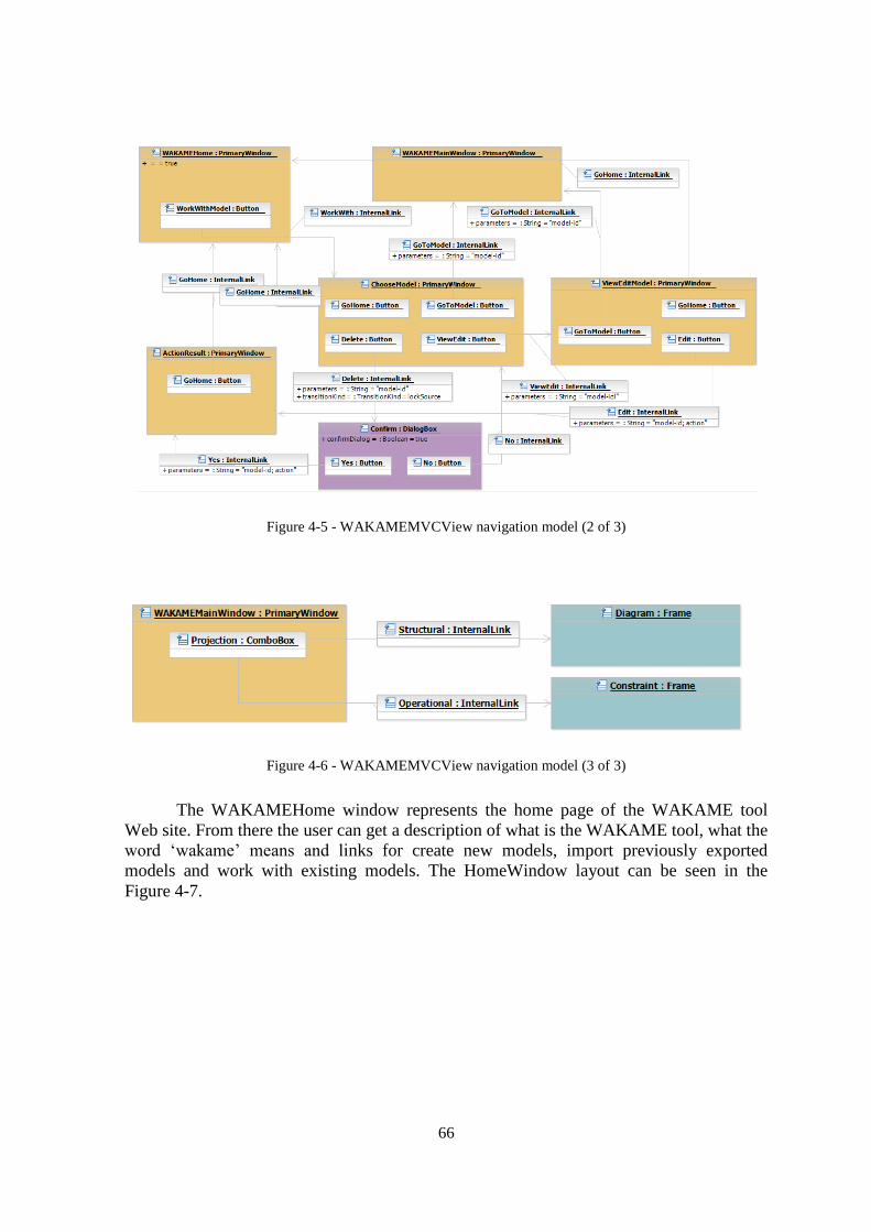
66
Figure 4-5 - WAKAMEMVCView navigation model (2 of 3)
Figure 4-6 - WAKAMEMVCView navigation model (3 of 3)
The WAKAMEHome window represents the home page of the WAKAME tool
Web site. From there the user can get a description of what is the WAKAME tool, what the
word ‗wakame‘ means and links for create new models, import previously exported
models and work with existing models. The HomeWindow layout can be seen in the
Figure 4-7.

67
Figure 4-7 - The WAKAMEHome Window Layout
From the home window of the WAKAME tool website, when the user clicks the
link CreateNewModel, it goes to the create model page, where it informs the model
metadata, like its title, description and who are the authors or collaborators of that model.
The Create NewModel screen layout diagram is exhibited in the Figure 4-8. From the
CreateNewModel window the user can also go back to the home window.

68
Figure 4-8 - The CreateNewModel Window Layout
After creating a new model, the user can go to the ChooseModel window, where is
shown a list of available models and where the user can choose the option to edit its detail,
work on it or delete the desired model. The layout of the ChooseModel window is shown
in the diagram of the Figure 4.7.
Figure 4-9 - The ChooseModel Window Layout
If the user chooses the option to edit the model details in the ChooseModel
window, the system shows the ViewEditModelDetails window, where the user can update
the metadata information associated with the model. This window‘s layout is depicted in
the Figure 4-10.

69
Figure 4-10 - The ViewEditModel Window Layout
Whenever an action is executed by the user, the results of the executed action is
shown in a window named ActionResults. This window shows whether the last operation
executed by the user was executed in a successful way or generated errors. The
ActionResults window is exhibited in the Figure 4-11.
Figure 4-11 - The ActionResult Window Layout

70
The user may also export his working model. By doing this, the model will be
exported to a XMI format. This file can be saved on the user‘s workstation and can be
imported into a new model in the WAKAME tool. The user can, by doing this model
export action, back the model up or to use the file in offline transformations, such as using
a custom parser to generate model variants, platform specific models, test cases or even
source code. To import an exported model back to a new model in WAKAME the user
may use the window ImportModel, which is depicted in the Figure 4-12.
Figure 4-12 - The ImportModel Window Layout
Another option available in the ChooseWindow is to work with an existing model.
This is the option required to perform model edition, like adding new constraints,
manipulate the components, views and so on. This window is the
WAKAMEMainWindow. This window has a left panel, where the user can choose which
kind of view he/she wants to access. The view is chosen by drop down menus, which
shows options to specify which is the current view, in terms of encapsulation, projection
and view or class/instance. In the right side of the WAKAMEMainWindow there are two

71
trees, one for navigational purpose and other that presents the existing types and
components that may be included in the current view.
The navigation tree shows the model‘s component tree, and when user selects one
specific component of this tree one view of that component is loaded by the tool. The
selected item in the tree represents the current component, that is, the subject component of
the view opened by the tool. The type tree shows all data types such as classes and
enumerations as well as components that the current component may have access. The
current component cannot access data structure which is not visible to the component, for
instance, types present in the realization of a sibling component. So these elements are not
shown in the type view.
Figure 4-13 - The WAKAMEMainWindow Layout
At the center of the WAKAMEMainWindow, there is a frame which shows text
data for operational views and diagram data to structural views. Bellow this frame, there is
one panel, which can exhibit messages to the user, such as information regarding the
executed operation or error messages. At the top of the diagram frame, there is a tool bar,
where the user may select which kind of element he/she wants to add to the current

72
diagram. Besides this toolbar, there is also a menu bar, where more options such as print
diagram, select all diagram elements, and send an element to foreground or background in
the diagram can be chosen. The layout of the WAKAMEMainWindow is described in the
Figure 4-13.
The WAKAMEMainWindow has the projection frameset which can exhibit a
diagram or a text editor based on current view‘s projection kind. If the projection is
structural a diagram is shown in the Projection frame, and if the projection is operational,
an OCL Editor takes place of the diagram. The editor frame, named EditorFrame, is shown
in the Figure 4-14.
Figure 4-14 - The EditorFrame Layout
Figure 4-15 - The DiagramFrame Layout

73
The diagram frame, called DiagramFrame, ocuppies the frameset Projection and is
used to draw/edit a diagram. The DiagramFrame owns the tool bar and has a Canvas for
the drawing of the Views‘s diagrams. The DiagramFrame layout is shown in the Figure 13.
4.2.3 The WAKAMEGUIController Component
The WAKAMEGUIController component inherits from the WebApp GUIController
abstract component. The WAKAMEGUIController is responsible for handling the server
communication and to control the WAKAMEMVCView component‘s windows and
widgets. These relationships are shown in the WAKAMEGUIController component
specification, depicted in the Figure 4-16. The modeling of this component corresponded
to the next step of the GUIPIMUF process, to specify the GUI elements behavior.
Figure 4-16 - The WAKAMEGUIController Component Specification
Internally, on its realization, the WAKAMEGUIController has four classes which
are event handlers:
ViewSelectionHandler – This class manages the actions regarding the selection of
the current view being exhibited by the tool. It handles the view kind drop down
menus selection that specifies the view and the selection of the subject component
class in the navigation tree.
ViewPersistenceHandler – The ViewPersistenceHandler is the class responsible for
handling user input events regarding to view persistence, such as sending the current
view state to the cloud, or getting a new view data from the cloud.
MenuHandler – Class that handles menu selections, like selecting all elements in the
diagram, deleting a specific element, or even printing the view‘s diagram.

74
ViewVolatilityHandler – This class handles events for inserting new elements to the
view or for dragging existing elements and dropping then inside the current view.
The WAKAMEGUIController component realization, with its handlers, can be observed in
the Figure 4-17 - The WAKAMEGUIController Component Realization.
Figure 4-17 - The WAKAMEGUIController Component Realization
The WAKAMEGUIController also needs to keep the current view state, like its
current elements, their positions, size, and so on. To be able to manipulate this information
it needs to access the model of the view, and this is represented by an association between
the WAKAMEGUIController component and the View class of the KobrA2 metamodel.
This association is shown in the Realization Structural Class Type view, which is exhibited
in the Figure 4-18.
Figure 4-18 - The WAKAMEGUIController Realization Types

75
The contract of the operations from the WAKAMEGUIController component and
its classes are defined as OCL constraints, according to the KobrA2 metamodel, and they
can be found in its realization operational class service view, and it is shown bellow.
The method actionPerformed present in ViewSelectionHandler class takes the
events that are instance of ChangeEvent and whose source is one of the view kind combo
boxes, such as Encapsulation and Projection. The value of the view property of the
WAKAMEGUIController gets updated with the new value from the combo boxes
selection, and the fromCloud operation is called in the WAKAMEGUIController, so the
new view could be loaded from the server. This is depicted in the Figure 4-19.
Figure 4-19 - The ViewSelectionHandler‘s actionPerformed() operation contract
The operation actionPerformed in the ViewPersistenceHandler class intercepts all
events of the ActionEvent kind and whose source is one of the buttons with label
fromCloud or toCloud, then the respective operation is called in the
WAKAMEGUIController component. The OCL expression containing the post condition
of this operation is depicted in the Figure 4-20.
Figure 4-20 - The ViewPersistenceHandler‘s actionPerformed() operation contract
The fromCloud operation present in the WAKAMEGUIController component
creates a new Request instance, fills the request attribute in order to obtain the new view
from the server, and send it to be processed by the WAKAMEWebService. The view

76
loaded from the server is extracted from the response which is the result of the operation,
and the related messages are exhibited in the Messages panel. The OCL constraint for this
operation post condition is shown in the Figure 4-21.
Figure 4-21 - The fromCloud() operation contract
The toCloud operation part of the WAKAMEGUIController component does the
inverse of the fromCloud operation. It creates a request to send the new view to be updated
into the model in the server. The results from the server validation are shown in the
Messages panel and the WAKAMEGUIController view is updated from the server during
this operation, because it may have changed it in the transformation process. The OCL
expression to the post condition of this operation is exhibited in the Figure 4-22.
Figure 4-22 - The toCloud() operation contract
The WAKAMEGUIController also keeps telling to the Diagram canvas to be
drawing the current view continually. This is done by the operation updateGUI. This
operation tells to the Diagram Canvas to be printing the view‘s contents over and over. The
OCL for this operation is shown in the Figure 4-23.

77
Figure 4-23 - The updateGUI() operation contract
The actionPerformed operation in the ViewVolatilityHandler class plays an important
role in the WAKAMEGUIController. It handles three important events, depicted bellow:
The event where the user has a button in a tool bar selected, let‘s say a Class, and
then he/she clicks in the Diagram canvas. In this case, if that element can be created
it is shown and created in the view corresponding to the selected item in the toolbar.
The event where the user drags something inside the Diagram canvas and he/she has
a button selected in the tool bar, for instance, this is done to create Associations. The
user has the Association button selected in the toolbar and drags from one element to
other element; a new Association is created into the view. In this case, the same
process occurs, if an element of the selected kind can be created, it will be created in
the correspondent view.
Finally, when the user drops a type or component dragged from the type tree, an
exact copy of that element that exists in other view is created inside the current view.
This also only occurs when the element can be present in the current view.
The allowance of an element to be present in the view is defined by its constraints
in the KobrA2 metamodel. This shall be observed at the moment of the element creation in
order to create views according the constraints presents in the KobrA2 metamodel. The
OCL for the operation of the ViewVolatilityHandler class is depicted in the Figure 4-24.

78
Figure 4-24 - The ViewVolatilityHandler's actionPerformed() operation contract
The MenuHandler class contains the operation actionPerformed which handles the
events performed in the application menus, such as Print, SelectAll and so on. The OCl
expression for the post condition of this operation is depicted in the Figure 4-25.
Figure 4-25 - The MenuHandler's actionPeformed() operation contract

79
This platform independent model was approved by the ORCAS research group
team and then the implementation took place, which is described in the Section 5.3.
4.2.4 Issues Raised during WAKAME GUI Platform Independent
Model
During the definition of the models, many issues has been raised and addressed.
Some of them are described in this section and organized into two main categories:
KobrA2 related issues and GUIPIMUF related issues.
KobrA2 Metamodel related issues:
It was needed to link the KobrA2 Metamodel elements with their representation in
each view, to follow the DI standard; this relationship was done by relating the
element of the view with the DI (Diagram Interchange) Metamodel. To accomplish
this, each element present in the view should be associated with one SemanticBridge,
which should be inherited from DI‘s SemanticModelBridge. Therefore, a
K2SemanticBridge was created, inheriting from SemanticModelBridge and
associated with the Element which is present in the view. This is shown in the Figure
4-26.
Figure 4-26 - The link between KobrA and DI's metamodels
It was necessary to draw the elements of each view into the screen in a proper way to
the end user. To do it, it was needed to make the Element from the view to inherit
from the GraphicElement class present in the GUIPIMUF 2D package. Hence, the
elements could be drawn to the screen considering their visual information stored in
the K2SemanticModelBridge. This is shown in the Figure 4-27.

80
Figure 4-27 - The link between the Element class from the Views package to the GUIPIMUF Graphic class
GUIPIMUF related issues:
The GUIPIMUF provides some standard dialogs present in most GUI environments.
However, it was needed some modifications on these dialogs, which are: (1)
specification of a new standard dialog which represents the Page Setup window,
where the user selects page size, orientation and so forth; and (2) changes in the
PrintDialog to specify which visual element needs to be printed.
All visual elements should inherit from the Graphic class present in the 2D package,
so they could be drawn and painted.
It was needed a way to specify what was the stack order of the elements in the
screen: an element with greater stack order is always in front of an element with a
lower stack order. Therefore we should be able to tell in the model which element
was at the top, being in the foreground and which one was in the background. By
adding this attribute, new operations like sendToBack(), sendToFront(),
sendBackward(), and sendForward() should be available.
Visual elements should have an attribute isSelected. It is important, for instance, to
tell which element is selected at the moment in a tool bar. To accomplish this, the
visual element should have a property to tell whether it can be selected and which is
the selection mode, if single (where only one element at the parent container could be
selected a time) or multiple (where the user should select more than one element at a
time). By default, all visual elements should have this attribute set as false.

81
When modeling elements which have a title or a label it is cumbersome to name the
element and to specify the same name in its title or label. In order to optimize the
modeling speed and to improve the layout diagrams, the label or text of the element
should be initialized with the element‘s name. So the user could not have to specify
the same information twice where the label or text is the same as its name.
In the drag and drop related events, the information about where the drag and drop
operation started was not available. This information is useful to specify what is
being transferred or moved to other place. It was also identified a necessity to specify
which kind of drag and drop was being performed, whether it was copying or moving
an element.
Another issue was the fact that to identify one element when specifying its behavior
in the screen was cumbersome, because the access to the element had to be
performed from the window to its children containers, until the desired element could
be reached. This was solved by adding an utility operation in the container class
named findElementByName(name:String):Element.
4.3. The WAKAME GUI Implementation and Unit Testing
Before the WAKAME GUI implementation a planning has been done where the
main activities defined were:
1. To analyze and chose implementation technologies;
2. Research for available frameworks that could help the implementation;
3. Research for open source diagramming tools;
4. Implementation of the GUI with the available items identified in steps 1, 2, and 3;
5. To make unit tests of the GUI;
6. To make integration tests with the WAKAME Web Service.
For the tool implementation, we had to choose a technology which would allow the
completion of the main tool goals stated in Chapter 3, that is, a technology which could
allow the tool to be loaded in a Web browser without the need of to download and install
the tool. The following technologies were analyzed:

82
Adobe Flash – Adobe Flash (previously called Macromedia Flash) is a multimedia
platform originally acquired by Macromedia and currently developed and distributed
by Adobe Systems (Flash, 2008). Flash has become a popular method for adding
animation and interactivity to Web pages and is commonly used to create animation,
advertisements, and various Web page components, as well as to integrate video into
Web pages, and more recently, to develop Rich Internet Applications (RIA). The
main drawback in the Adobe Flash use is that it is a proprietary technology.
Scalable Vector Graphics (SVG) – SVG is a family of specifications of XML-based
file format for describing two-dimensional vector graphics, both static and dynamic
(interactive or animated) (OMG, 2008). The SVG specification is an open standard
that has been under development by the World Wide Web Consortium (W3C) (W3C,
2008). SVG images and their behaviors are defined in XML text files. This means
that they can be searched, indexed, scripted and, if required, compressed. The main
drawback in the use of SVG comes to the fact that the Internet Explorer, the most
used Web browser until 2009, does not support SVG directly. A plug-in needs to be
installed and very few people have it available on their Internet Explorer installation.
DHTML – Dynamic HTML, or DHTML, is a collection of technologies used
together to create interactive and animated Web sites by using a combination of a
static markup language (such as HTML), a client-side scripting language (such as
JavaScript), a presentation definition language (such as CSS), and the Document
Object Model (W3Schools, 2008). DHTML allows scripting languages to change
variables in a Web page's definition language, which in turn affects the look and
function of otherwise "static" HTML page content, after the page has been fully
loaded and during the viewing process. Thus the dynamic characteristic of DHTML
is the way it functions while a page is viewed, not in its ability to generate a unique
page with each page load. Until HTML4 which is in 2009 the current HTML
specification supported by browsers, DHTML could not access a native canvas in the
browser for graphic manipulation. It had to been done with images and the support to
work with these graphics is poor.
Java Applets - An Applet is a small application written in the Java programming
language which are included in an HTML page. Java Applets are used to provide
interactive features to Web applications that cannot be provided by HTML. Since

83
Java's byte code is platform independent, Java applets can be executed by browsers
for many platforms, including Windows, UNIX, Mac OS and Linux. When a Java
technology-enabled browser views a page that contains an Applet, the Applet's code
is transferred to the clients system and executed by the browser's Java Virtual
Machine.
Due to the capability and existing support in Web browsers to Java Applets and Adobe
Flash they were chose as main options to develop the application. But we choose Java
Applets due to the following aspects:
Java is an open source technology, what implies in continuity and availability of the
technology in the future;
There are wide open source Integrated Development Environment (IDEs) such as
Eclipse (Eclipse, 2009) and Netbeans (Netbeans, 2009) availability to support Java
Applets development, what makes the development faster and more productive
without having to rely in a paid IDE to achieve high productivity;
The tool written as Java Applets could be bundled in a Java Archive (JAR) and to be
used as an ordinary desktop application, which could simplify its use for users who
does not have a broadband Internet connection;
There are several open source libraries to deal with graphic manipulation in Java,
which could make the construction of the diagram editor easier;
In the same way there are several libraries for graphic manipulation, there is a large
number of open source UML tools written in Java available, allowing us to reuse
existing code without having to reinvent the wheel, and simplifying once again the
the tool development;
Another criteria used in the decision was the fact that we have wide knowledge in the
Java technology, what implies in not to have to learn a new technology to develop
the tool.
After choosing Java Applets as the implementation technology of the tool, we started to
look for existing Java graphic manipulation libraries and frameworks which could help in
the tool implementation. Without the aid of a graphic editing library, it would be
cumbersome to implement elements position handling, drag and drop, to move elements
relationships without to lose their aspect, etc.

84
During this phase of the work, where we analyzed graphical editing frameworks,
open source diagramming or UML CASE tools that were built using these libraries and
frameworks was also identified, since we could reuse part of these tools. The following
libraries were identified and analyzed as a candidate option as graphic manipulation
framework:
JGraph – JGraph is a powerful, lightweight, feature-rich, and thoroughly documented
open-source graph component available for Java (JGraph, 2008). With the JGraph
zoom able components, its user can display objects and relations (networks) in any
Swing UI. JGraph can also be used on the server-side, for example to read a Graph
eXchange Language (GXL) format graph, apply a custom layout algorithm, and
return the result as a HTML image map.
Java Graph Editing Framework (Tigris GEF) – The word Tigris has been added here
to differentiate this framework from the Eclipse project which has the same acronym.
Tigris network hosts this project at http://gef.tigris.org (Tigris, 2008). The goal of the
Tigris GEF project is to build a graph editing library that can be used to construct
many, high-quality graph editing applications. A simple, concrete design that makes
the framework easy to understand and extend. Node-Port-Edge graph model that is
powerful enough for the vast majority of connected graph applications. Model-View-
Controller design based on the Swing Java UI library makes GEF able to act as a UI
to existing data structures, and also minimizing learning time for developers familiar
with Swing. High-quality user interactions for moving, resizing, reshaping, etc.
Graphical Editing Framework (Eclipse GEF) – The word Eclipse was introduced to
differentiate this framework from the other one with the same acronym hosted at
Tigris network (GEF, 2008). The Eclipse foundation hosts the Graphical Editing
Framework. The Eclipse GEF allows developers to take an existing application
model and easily create a rich graphical editor. Eclipse GEF allows a developer to
quickly map any existing model to a graphical editing environment. The graphical
environment is the SWT-based drawing plug-in "Draw2d". The developer can take
advantage of the many common operations provided in GEF and/or extend them for
a specific domain. GEF is suitable for creating a wide variety of applications,
including: flow builders, GUI builders, UML diagram editors (such as work-flow and
class modeling diagrams), and even WYSIWYG text editors like HTML.

85
OpenJGraph – OpenJGraph is a Java library to create and manipulate graphs. Its
features include directed, undirected, directed-acyclic, and weighted graphs, and
simple graph algorithms such as graph traversal, minimum spanning tree, and
shortest path spanning trees for weighted graphs (OpenJGraph, 2008). The library
also has some support for graph drawing, including straight line and orthogonal
graph drawing, and for user interaction such as creating and removing a vertex,
creating and removing an edge, dragging a vertex, and changing some of the vertex
and edge properties.
NetBeans Graph Library - Graph Library has been designed to support visualization
and editing of node-edge structures using drag and drop style of work (Netbeans,
2008).
The best options here were defined as being Eclipse GEF and Tigris GEF due to its
respective success cases shown in Eclipse and in Argo UML (which is built on top of the
Tigris GEF). As Eclipse GEF could not be loaded in a Java Applet or in a Web browser
due to SWT (technology which Eclipse GEF is built in) native characteristics, Tigris GEF
was used in this work. From now on, the term GEF refers to the Tigris GEF.
The implementation of the tool occurred then with Java as underlying technology
and Java Applets as front-end, although a Java Swing front-end is also available in the tool,
for the its use outside the Web browser. This was done by following the Platform
Independent Model specified in Section 4.2.
In order to keep organized the WAKAMEGUI software configuration, the
Subversion version control software was used. A repository for managing all source code
changes was created and used until the end of the implementation.
During the tool implementation some parts of the GEF had to be changed to support
loading icons and internationalization within Java Applets, and the drawing of the main
UML elements such as classes and relationships were reused from Argo UML project. As
Argo UML was built on top of GEF this task were simplified in parts, but it was still
needed a large amount of work to make the reused code work without its Argo‘s source
code dependency.
Another important aspect of the tool implementation was the reuse of an existing
lightweight open source Java text editor which provides syntax highlighting, auto

86
completion, and find/replace functionality among other features. These features would be a
must for editing the KobrA2 operational views.
Therefore, the selected open source Java text editor used was JSyntaxPane, a very
simple to use and extend code editor (JSyntaxPane, 2008). The main goal of the
JSyntaxPane project is to make it easy to have nice looking Java Swing Editors with
support for syntax highlighting. Even knowing it was a lightweight component, it was
adapted, and its support to highlighting languages such as Python and PHP was cut off
since it was going to be integrated to the WAKAMEGUI, and should be as small as the
possible, to fit WAKAMEGUI lightweight goal. Besides this cutoff, we defined inside of it
basic completion and syntax highlighting of OCL expressions, which was inexistent.
Figure 4-28 - Debug messages in the WAKAME Main Window
During the implementation we also executed unit testing and as bugs were found
they were corrected, in order to make a functional tool. These tests were completed in the
developer‘s environment as well as a Web application where the features were confirmed
to work under Java Applets limitations. To simplify testing and debugging the message
panels, which was intended to show warning and success messages about the tool
operation, such as a warning regarding an association between elements which is not
allowed by the KobrA2 specification, was used to exhibit debug messages. It was
implemented also a time tracker, to check load time of diagrams in the tool. This load time
was composed by two parts, server load time, which contains the time needed to the tool to

87
get the view from the server, and GUI load time, that represents the time needed to the
GUI client to process the response received from the server and show the diagram in the
screen. One picture exhibiting debug messages and load time is shown in the Figure 4-28.
After the implementation, a statistical source code analysis was done by using the
tool State of Flow Eclipse Metrics (Eclipse Metrics, 2009). These results are shown in
Table 4.1.
Table 4.1 - WAKAMEGUIClient source code metrics
Statistic Value
Packages 35
Classes 619
Total of Lines of Code 65,653
Size of Implementation 4.05MB
Size of JAR 1.40 MB
The total of lines of code, packages and classes does not take in account the
JSyntaxPane component which was also included in the GUIClient for OCL editing. From
this total, around 60% of the code was reused from open source projects, mainly the GEF
framework. The implementation covered also 70% of the platform independent model
specified. Some views which used protocol state machine, instance and activities diagrams
were left behind due to time restriction, and were implemented only the essential KobrA2
views.
4.4. The WAKAME GUI Integration, Integration Testing and System Testing
Also after the GUI implementation, we started to integrate the GUI with the
WAKAMEServer, which was going to act as model repository and to deal with the
transformations between KobrA2 views.
For the integration of the WAKAMEGUI with the WAKAMEServer, it was set up
an application in Google App Engine, which could hold the server and client applications.
This was done in order to have a testing environment which was going to be very similar to
the production environment, which was ideal for the tests. This environment can be
accessed through the Web page http://wakameemf.appspot.com. Besides the environment
preparation, I and Breno Batista Machado (a maters student at the CIn/UFPe) who was
working with the server side of the application, defined the communication infrastructure
and data interchange format between the WAKAMEGUI and the WAKAMEWebService.

88
At this moment, for software version control of the WAKAME tool code, a common code
basis between server and client was also created in a Subversion project, so all the code
would be in a single location and have its control simplified (Subversion, 2008). All code
from the WAKAMEGUI and WAKAMEWebService was moved to the new Subversion
project.
The communication infrastructure between the WAKAMEGUI and
WAKAMEWebService used was plain HTTP requests and responses and the data being
always transferred in the JSON format, which provides easier to read and lighter option as
compared to XML (JSON, 2009). The existing bugs found during the integration were
corrected as they were identified.
For the system testing of the WAKAME tool, we used the same environment that
was used for integration testing and we created a project named WAKAME in Google
Project Hosting (Google, 2009) infrastructure to enhance our work coordination and follow
ups. This project can be accessed through the Web address:
http://code.google.com/p/wakame. An issue tracker in the WAKAME project was used to
manage incidents, enhancement opportunities and tasks. This would help us to track
existing issues, allow interested people in some issue to follow them up, to easily make
new users to give us feedback to the project. By using this infrastructure we can inform in
a new issue its description, if it is related to the Component UI, Logic and Persistence, who
is the owner of that issue, its status and keep the full history of the issue, among other
useful features. When an issue is created you may chose to be notified about all changes
into that issue by email. A screen for registering a new issue can be seen in Figure 4-29.
Using the issue tracker the user can also see all open issues, as well as to filter them
by some criteria, such as reporter, owner, status or description. Any tool user can also vote
to choose which issue he/she wants to be addressed first. A list containing some issues in
the issue tracker is shown in the Figure 4-30.
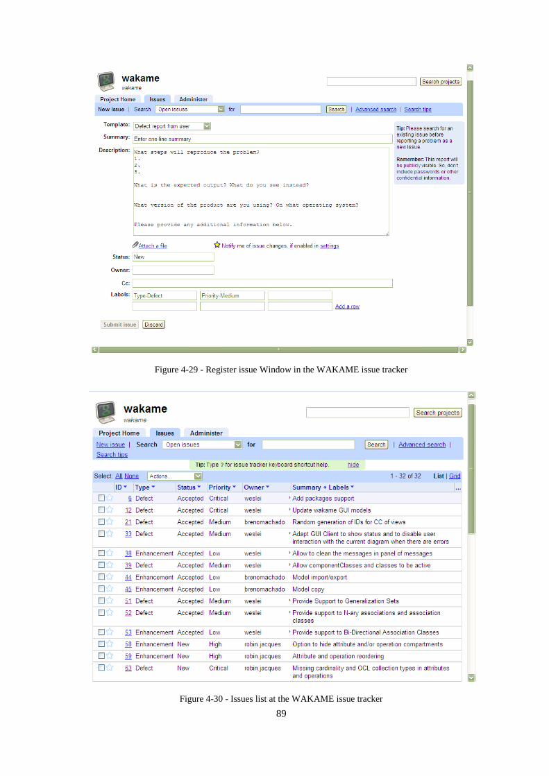
89
Figure 4-29 - Register issue Window in the WAKAME issue tracker
Figure 4-30 - Issues list at the WAKAME issue tracker

90
4.5. The WAKAME Publishing
The tool is still under work, but many bugs have been fixed and many
enhancements and suggestions were implemented. A website for live performance of the
tool was created and it can be accessed by the URL http://wakametool.appspot.com.
The tool at the time of this writing is exhibited bellow. First in the Figure 4-31 the
home window of the WAKAME tool is shown. From there the user can import a model,
create a new model or to go to the choose model screen, where he/she can work with the
model, delete or edit its metadata. The ChooseModel window is shown in the next figure,
the Figure 4-32.
Figure 4-31 - The WAKAME tool Home Window

91
Figure 4-32 - The WAKAME tool ChooseModel Window
When the user selects the option to view or edit the model details it is brought to
the ViewEditDetail window. This window is shown in the Figure 4-33. After a successful
action execution the ActionResult window is shown, like the example in the Figure 4-34.
Figure 4-33 - The WAKAME tool ViewEditModel Window

92
Figure 4-34 - The WAKAME tool ActionResult Window
The window for creating a new model and the window for import an earlier
exported model to XMI are exhibited respectively in the Figure 4-36 and Figure 4-35.
Figure 4-35 - The WAKAME tool ImportModel Window
From the ChooseModel window, the user can start working with a model. This is
done in the WAKAMEMainWindow screen. This screen can be seen in the Figure 4-37,
where the edition of the Specification Structural Service Class of the Inventory Manager

93
component takes place. The left, right and messages panes are all resizable and can be
hidden with a mouse click by the user.
Figure 4-36 - The WAKAME tool CreateModel Window
Figure 4-37 - The WAKAME Main Window
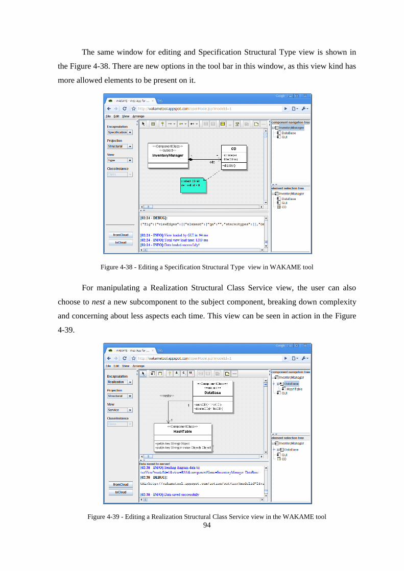
94
The same window for editing and Specification Structural Type view is shown in
the Figure 4-38. There are new options in the tool bar in this window, as this view kind has
more allowed elements to be present on it.
Figure 4-38 - Editing a Specification Structural Type view in WAKAME tool
For manipulating a Realization Structural Class Service view, the user can also
choose to nest a new subcomponent to the subject component, breaking down complexity
and concerning about less aspects each time. This view can be seen in action in the Figure
4-39.
Figure 4-39 - Editing a Realization Structural Class Service view in the WAKAME tool

95
Whether the view kind is operational, the Diagram frame leaves, and the Editor
Frame takes place, allowing the user to manipulate the required OCL expressions. This
editor can be seen in the Figure 4-40.
Figure 4-40 - Manipulation of an operational view in the WAKAME tool
When the user tries to insert an element which does not conform to the KobrA2
metamodel, a warning message is exhibited in the messages panel, warning the user about
her action. One example of this warning message can be seen in the Figure 4-41, after the
user tries to add a nests association from a non subject component class.
Figure 4-41 - Warning Message in the WAKAME tool Main Window

96
4.6. Chapter Remarks
This chapter exhibited the steps related to the creation of the WAKAME GUI tool,
including its models definition, the technology selection for implementation, the
construction of the tool following its Platform Independent Model, the issues raised,
integration and testing of the tool and the tool itself.

97
CCHHAAPPTTEERR 55..
AASSSSEESSSSMMEENNTT
EEXXPPEERRIIMMEENNTTSS WWIITTHH
EEAARRLLYY AADDOOPPTTEERRSS
This chapter exhibits the evaluation of the WAKAME tool against the IBM Rational
Software Modeler tool, the obtained results and our findings.
5.1. Experiment Definition
A productive way to assess whether a case tool fits its purpose is to determine the business
objectives that the tool should met and then compare the tool against these objectives.
After the analysis of several CASE tools, we states that the common features that a CASE
tool should provide are mainly classified in terms of:
Availability – This criteria relates to the degree in which a system, subsystem, or
equipment is operable and in a committable state at the start of a mission, when the
mission is called for at an unknown, i.e., a random, time. In short, availability is the
proportion of time a system is in a functioning condition. Availability also relates to
the ratio of (a) the total time a functional unit is capable of being used during a given
interval to, and (b) the length of the interval.
Performance – Computer performance is characterized by the amount of useful work
carried out by a computer system compared to the time and resources used. It may be
defined in terms of short response time for a given piece of work, high throughput
(rate of processing work), low utilization of computing resource(s), high availability
of the computing system or application, fast (or highly compact) data compression
and decompression, and high bandwidth / short data transmission time.

98
Ease of use – The term ease of use is used to denote the how ease a people can
employ a particular tool or other human-made object in order to achieve a particular
goal.
Diagram layout control and legibility – This aspect relates to the amount of control
the user has over the working diagram and how legible is the diagram for the user.
Standard compliance – This criteria takes in consideration aspects related to whether
the tool is adherent to its standards and constrains the models created by the user to
fit these standards.
However it is very difficult to obtain objective measurement data to determine
whether the tool could fit these goals, or even to state the level of its agreement, since they
have high subjectivity. Therefore we decided to compare the performance of the
WAKAME tool with another tool. This comparison happened according to the identified
business objectives, and the modeling performance could be measured considering the
same business objectives in both tools. For accomplish this, we needed to choose a CASE
tool where the user could create KobrA2 models and that meets the following constraints:
UML 2 compliance - For being compliant to the UML 2, a tool should present both:
concrete and abstract syntax compliance. Concrete syntax compliance, relates to
whether users can continue to use a notation they are familiar with across different
tools and have their communication easier, because the elements could have the same
meaning across different tools. Abstract syntax compliance means that users can
move models across different tools, even if they use different notations, what is
essential when the language is used as a basis for model-driven development. The
user might want to use tool A for creating the model, tool B for validating the model,
tool C for somehow transforming/enhancing the model and tool D for generating
code from it, this is only possible if all the tools are compliant to the UML 2 abstract
syntax.
OCL 2 support – The tool should be compliant with the OCL metamodel and to
support constraints as well.
Availability – The tool should be available for use, so if the tool A is proprietary, and
we have no license for its use, it could not be used in the comparison.

99
Industry acceptance – The tool had to be widely accepted by the software industry
around the globe. By satisfying this constraint, the tool would be considered one of
the most important tools in its application area.
Portability – The tool should be able to operate under different platforms, so its user
would not be restricted to use tool under one specific environment.
Multi user support – The tool should allow different users to shared and work on the
same model.
For comparison, the tool we found that met these constraints was the IBM Rational
Software Modeler (RSM). The RSM could offer both, high and concrete syntax
compliance to the UML 2 metamodel and support to OCL 2 expressions. Regarding its
availability, we had academic licenses of this tool at UFPE, place where the case study was
executed, and the RSM tool has high industry acceptance as an UML and model driven
CASE tool. The IBM RSM is also developed in Java technology what means that it can
work in different operational systems and hardware platforms, and it enables multiple
developers working with the same model through the use of an external version control
system.
Once defined the experiment, its goals and the tool that was going to be used, we
had to choose a KobrA2 model for the experiment. We decided to use a representative
KobrA2 model, in terms of number of components, number of views and model
applicability. The chosen model was the KobrA Web App Framework, which comprises 8
components with a total of 18 views and represents a real world model, being also part of
this work (Section 3.2). The KWAF model was also consolidated, so the experiment
participants would not have to take design choices, or to create the model from scratch.
Instead, they would follow the existing model, and focus their attention only on the model
creation.
To the user‘s evaluation, we developed a survey, which would take in account
aspects related to availability, performance, ease of use, diagram layout control and
legibility and standard compliance, since these were our main goals to meet. These criteria
and the survey coverage to them are explained bellow:
Availability – At the survey, the availability questions were related to time and ease
of installation of the tool and the ease to setup one environment for multiple users
collaborate in the same model.

100
Performance – This criteria has been broken down into the survey in questions
regarding startup time; upload and download time from and to a persistent medium;
and resource consumption (RAM, CPU, network bandwidth).
Ease of use – In the survey, the ease of use was taken in account by considering the
number of menus needed to go through to start drawing models, the number of
actions (clicks, go to pane, fill up fields, etc.) needed to add a model element or
property, the number of features on the screen that you do not understand and need,
ease of navigation between various diagrams of the same model, ease of previously
created model elements for inclusion in current diagram, and ease of drag and drop
elements between diagrams and overall modeling speed.
Diagram layout control and legibility – In the survey, this aspect was covered by
questions related to the ease to change diagram layout (boxes and links), legibility of
automatically re-laid-out functionality (after change), maximum size of diagramming
area which is based in the ability of hide unwanted elements in the screen to
maximize the working area and ease of undoing changes.
Standard compliance – This aspect was broken down in the survey questioning
metamodel non-conformance detection, helpfulness of warning messages, enforced
coherence between several diagrams of the same model and ease of introducing
process-specific constraints on models.
The user could fill in the survey questions regarding these criteria about IBM
Rational Software Modeler and the same questions about WAKAME tool. The survey also
contained questions regarding the user‘s education level and both tools familiarity.
In order to participate of the experiment, we invited the ORCAS Research Group
members, which comprise researchers of different scholarship degree, starting from
undergraduate students to PhD holders. They also have different levels of knowledge about
KobrA2 and experience in IBM RSM tool.
After the definition of the experiment goal, the tool that we were going to compare
WAKAME with it, the comparison criteria and the experiment participants, we created a
planning for the case study execution. Therefore, a schedule for the experiment was
defined containing the following activities:

101
1. Presentation of the KobrA2 method to the participants, its principles, the main views
and sample views;
2. Presentation of the KWAF model, which was going to be modeled by the
participants in the two CASE tools;
3. Distribution of the case study;
4. Installation of the IBM RSM at the computers that do not have it;
5. Half of the participants model for 50 minutes using the IBM RSM, while the others
model with the WAKAME tool also for 50 minutes;
6. After 50 minutes, who were modeling with the IBM RSM starts to model with the
WAKAME tool, while the other group would take the IBM RSM;
7. After finishing the specified time the participants were surveyed about their
experience in modeling with both tools (Appendix A).
5.2. Execution and Analysis of the Case Study
For the execution of the case study, a room was reserved for accomplishment of the
presentation and to make possible that all the participants were in the same atmosphere to
not suffer influences of different external factors.
Among the 26 members of the ORCAS research group invited to participate, only
fourteen attended. The execution happened according to the planned stages, being: 30
minutes for the presentation of the KobrA2 method; 20 minutes for the presentation of the
KWAF model; 40 minutes for the installation of the IBM RSM tool; and, 1 hour and 50
minutes for the accomplishment of the models by the participants (50 minutes in one tool,
10 minutes for interval, and 50 minutes in another tool). After these stages, all the
participants answered the survey.
Among the participants, eight didn‘t possess the tool RSM installed in their
computers and they had to accomplish this installation. The IBM RSM application has
approximately 1.2 GB of size in disk and after the installation it occupies 980 Mb
approximately. The installation of RSM in the participants‘ computers happened without
problems, and it took on average 15 minutes each installation.
Now we will present the results obtained in the research. The Figure 5-1 displays a
graph with the educational level of the case study participants. It can be observed that the

102
educational level among the participants was diversified, tends, from undergraduate
student to a person PhD. holder. Already the participants‘ experience with the RSM and
WAKAME tools can be seen in the Figure 5-2, where it can be observed that most never
used none of the both tools. However, we see a larger number of people that already had
some contact with RSM than with WAKAME.
Figure 5-1 - Educational Level of Participants
Figure 5-2 - Familiarity of the Participants with the RSM and WAKAME tools.
The first item verified in the case study was the percentage of the models
accomplished in each tool by the participants in the given time (50 minutes). To calculate
this measured, the weight of each view of the model used for the case study was defined
through the amount of existent elements: ComponentClasses, Classes, Enumerations,
Operations, Attributes, Parameters, Associations and Stereotypes (since the same is not
generated automatically in RSM as it is in WAKAME). For the operational views, that are
just textual for the OCL constraints writing, the weight ONE was defined. The Figure 5-3
exhibits the percentage of the model done in each tool, for each participant, where each
line represents a participant (P1 to P14). The left side of the graph represents the
percentage done in WAKAME and the right side the percentage done in RSM. The graph
bellow exhibits the general average, of all the participants, of the percentage done in each

103
tool. Observing these results, we can say that the time spent for modeling in RSM is
approximately the double of the time spent in WAKAME.
Figure 5-3 – Model Completeness Comparison.
Looking more closely, in comparison with Table 5.1, we noticed that only the
participants that already had some contact with the RSM tool got to model at least 40% of
the proposed model, differently of the result obtained by WAKAME, where all did more
than 40% of the model. It was also observed that the participants P2 and P3, that never had
contact with the WAKAME tool, got to complete the modeling. However, it is also
observed that these two participants, and the others that got finish the model in the
WAKAME tool, P1, P8, P9 and P10, already had at least some contact with the RSM tool.
Of these observations, we can say that the WAKAME tool possesses a better
performance for the accomplishment of KobrA2 models, on average the double of the
performance in relation to RSM, and for users that already had some contact with the
RSM, the learning curve is very low, as in the participants‘ case P2 and P3. Finally, it is
noticed that the participants that never had provided with none of the two tools had the
lowest performance.

104
Table 5.1 - Familiarity of Participants with the Tools RSM and WAKAME.
How familiar are you with the Tool?
WAKAME RSM
P1 Used a few times Used a few times
P2 Never used Used a few times
P3 Never used Several months of self-taught use
P4 Never used Never used
P5 Never used Never used
P6 Never used Never used
P7 Never used Never used
P8 Used a few times Used a few times
P9 I am a trained expert Several months of self- taught use
P10 I am a trained expert Several months of self- taught use
P11 Never used Never used
P12 Never used Never used
P13 Never used Never used
1P4 Never used Never used
After having done the analysis of the percentage of the models accomplishment, the
analysis of the answers from the participants to the form began, we compile these answers
by criteria.
Figure 5-4 –Availability Related Answers Comparison.
The first criterion to be analyzed is Availability (Figure 5-4). It can be observed
that the RSM tool had in larger part the answers Sub-par and Dismal for both questions
done, while WAKAME had most of the answers Excellent. A possible reason for this fact
is that RSM possess a relatively slow installation process and the same has a difficult
download process. Another fact is that RSM does not possess any preinstalled tool for aid
in the teamwork development, being necessary the plug-in installation. On the other hand,
the WAKAME tool, for being Web, is easily accessible and for its execution it is necessary
just to download the necessary JARs file, which the browser automatically does. The size

105
of these necessary files is of approximately 1.5 Mb, almost a thousand times minor than
the RSM installation file.
In the criterion Performance (Figure 5-5), the first question refers to the necessary
time to start the tool, for it to be ready for the use. In this point, in understanding of the
participants, the WAKAME tool had a better performance than the RSM tool, being most
of the answers Good enough for WAKAME against Sub-par for RSM. In this case, the
time spends of start-up of WAKAME is practically the time spend for the download of the
necessary files, because, due to its reduced size, the download is fast. Yet RSM, for being a
quite robust tool, and also for using the Eclipse‘s platform its time of load to the memory is
large, though it is not necessary to download any file.
Figure 5-5 - Performance Related Answers Comparison.
The second question, of the Performance criterion, refers to the necessary time to
load and to save a model in a persistent medium. The RSM had a better evaluation in
relation to the other questions of this criterion. It occurs because the persistent medium
used by RSM is the local disk of the computer, which possesses a fast access, but the
processing necessary to do it still little costly. As the medium of persistence used by
WAKAME is in the cloud, the result of this subject is directly tied to the user‘s band

106
width. In this case, as the case study was accomplished at CIn/UFPE, and it has a
satisfactory access to the internet, WAKAME obtained a good result.
The last evaluated question of the Performance criterion was related to the
consumption of computational resources. Again, WAKAME had the results between Good
enough and Excellent, because its client component is light and it demands little processing
and memory, but it already makes use of a considerable band width. Yet the RSM had the
majority of the answers Sub-par and Dismal, due to its size, consuming a lot of processing
resource and memory. To execute the RSM satisfactorily it is necessary a machine with a
good hardware configuration, different from WAKAME, which does not have this need.
The next criterion evaluated, Ease of Uses, that can be considered one of the most
important, because if a tool is complicated to use its learning curve is high and,
consequently it is necessary a high investment for its adoption, what usually discourages
the tool adoption. In general, WAKAME obtained very good evaluations in contrast with
the terrible evaluations of RSM, what can be perceived in the Figure 5-6. This happened
because RSM is a tool with several objectives and with support to several functionalities,
what generates an enormous overhead of information and options for work. Differently,
WAKAME was projected to assist only the needs of the KobrA2 method, leaving its
interface simple with only the necessary information and options.
The first question of the Ease of Use criterion has the intention of evaluating the
necessary ―effort‖ to begin modeling, in other words, how many screens, how many choice
options, how many buttons are necessary to click for the user begin to writhe the model.
WAKAME has the option of accessing a model already existent or to begin a new one. To
access an existent model the user should access the page of models listing, to choose the
model wanted in the combo-box and, finally, to access the modeling screen. For the
creation of a new model, the user should access the page of model register, in which is
necessary to fill out few information and after this to make the process described to access
an existent model. That is contemplated in the result of the evaluation with most of the
answers Excellent, due to the easiness and intuitive access/creation of models.
To access a model in RSM, so a new model, as a model already existent, it is
necessary, in the beginning of the tool execution, to choose the wanted workspace, as the
whole tool that is based on Eclipse. After this, it is necessary to choose the creation of a
new modeling project, among the several other different project options. Then it is

107
necessary to choose, among several options of modeling templates, which will be used for
modeling, to finally to begin modeling. To access an existent model it can be done directly,
if the same is already in the work place, otherwise, it is necessary to do the whole
procedure of project import provided by the Eclipse. In the case study, it was noticed
certain difficulty among the participants that never had contact with RSM to begin a new
model. This occurred because if the chosen modeling template is not the most specific,
some necessary modeling elements for KobrA2 are hidden.
The next question of the Ease of Use criterion has as objective to measure the
usability in agreement with the amount of necessary clicks to include a new element in the
model, or a new property of an existing element. In this case, WAKAME was evaluated, in
the major part, as Excellent and, the RSM as Dismal. As dictated previously, WAKAME
only makes available what is necessary for the view in subject, facilitating like this, the
insertion of a new element. To add properties of an element, in WAKAME it happens
through the inclusion of its concrete syntax, without the need to access the properties
palette, as in RSM. In the question regarding the number of available features for the user,
the evaluation was similar to the previous, this happened because of the same reason
already explained before – WAKAME only exhibits the necessary and RSM, because of its
general purpose, exhibits more information and options than the user usually needs.
The next three questions of the Ease of Use criterion refers to the navigation and
the easiness to include items in diagrams. In the first one, that it is the navigation easiness,
WAKAME had a good evaluation, in contrast with RSM. That is due to the fact of the
navigation in WAKAME to be guided through component and the orthographically options
of the views. Yet in RSM, depending on the nesting of the packages, to navigate through
the diagrams becomes very complex. However, in the other two questions, regarding the
inclusion of existent elements in different diagrams both tools had a similar result, where
WAKAME was between Good enough and Excellent, and RSM among Dismal, Sub-par
and Good enough.
The last question of Ease of Use refers to the speed for the creation of models. This
question depends directly of the previous evaluations, because, a tool with a good usability
usually possesses a good speed for development due to the learning curve, simplicity and
intuition of its interface. Due to the simple and objective interface for the KobrA2 method,
the time spent to model KobrA2 in WAKAME is much smaller than in RSM.

108
Figure 5-6 - Ease of Use Related Answers Comparison.
Another evaluated criterion was Diagram Layout Control and Legibility, where the
result can be seen in the Figure 5-7. In the first two questions WAKAME had a good
evaluation, because its interface allows easily manipulation of the size and position of the
elements and mainly it allows total control above the disposition of the links in the model.
Yet in RSM, its low rate in this criterion, pointed by the participants, is due because of its

109
low usability, mainly for the manipulation and links formatting that the tool possesses. In
the question regarding the maximum area of the diagram, both tools had a good appraised
performance, because both possess resources to hide the undesirable options and to exhibit
only the modeling area. However, WAKAME was gotten a larger useful area than RSM.
The last question of the criterion mentioned above, concerns to allow to undo
modifications, WAKAME had an inferior evaluation then RSM. This occurs because
WAKAME still does not possess the functionality to undo actions. However, WAKAME
allows not to save the modifications done (before sending to cloud) and to bring the
information from the cloud and overwrite the current information. Yet RSM obtained the
evaluation Good enough, because it provides the action Undo, even this not work for a
certain subset of actions.
Figure 5-7 - Diagram Layout Control and Legibility Related Answers Comparison.
The last appraised criterion was Standard Compliance. Were appraised questions
as: the detection of no conformities with the metamodel, the capacity to express the non
conformities through warning messages, the capacity to maintain the coherences of
elements that appear in several diagrams and the capacity of inserting specific restrictions
of process in the model.

110
Figure 5-8 - Standard Compliance Related Answers Comparison.
The Figure 5-8 shows the results of this criterion, where WAKAME stood out in
the capacity to verify no conformities in the model, in the capacity to maintain the
coherence between the diagrams (views) of a model (SUM) and in the capacity to include
specific restrictions of process in the model. However, in the subject regarding warning
messages, WAKAME received Good enough and Sub-par. Yet RSM, had an evaluation
close to Dismal and Sub-par, except for the question regarding the checking of no
conformities, because in this case RSM made these verifications in the UML model level.
5.3. Experiment Findings
During the execution of the case study, some new issues of the WAKAME tool were
discovered, and properly reported in the issue list of the project.
This experiment allowed us to observe that the productivity on KobrA2 modeling
was greatly increased with the use of Web GUI. The results show that a larger part of the
model is completed in WAKAME within the same time box. Therefore, the use of a Web
GUI supporting orthographic design concept for KobrA2 modeling increases greatly
modeling productivity.
Another factor observed, that was not in the survey, is that the participants that
didn‘t know none of the tools, didn‘t also have knowledge, or had little knowledge, on
KobrA2. Differently, the participants that already knew one of the tools, already possessed

111
a reasonable knowledge about KobrA2. The factor of a participant to have knowledge in
KobrA2 might have influenced his performance in WAKAME.
Also this case study helped to show improvement points in the tool, as example, the
need of the functionality Undo, also the need to define a way to reduce the traffic of data in
the net in way to improve the warning messages.
It is important to emphasize that WAKAME is a specialist tool, in the sense of
assisting only the KobrA2 method, differently of RSM that is of general purpose. This
makes possible that WAKAME has a simple interface and a low learning curve in relation
to RSM, for models done in the KobrA2 method.
In general WAKAME had a better performance in relation to RSM, in almost all
points evaluated. Making a weighted average of the answers of the questions related to
amount of answers (considering Dismal - 1, Sub-par - 2, Good enough – 3, and Excellent -
4) we have in Table 5.2 the summary of the evaluation.
Table 5.2 – Assessment Summary
Assessment Summary
WAKAME RSM
Availability Excellent (4) Sup-par (2)
Performance Good enough(3) Sub-par(2)
Ease of use Excellent(4) Sub-par(2)
Diagram layout control and
legibility
Good enough(3) Sub-par(2)
Standard compliance Good enough(3) Sub-par(2)
With the data of Table 5.2 we noticed that the strong points of the WAKAME tool,
in general, are its availability, for being web, and its use easiness, consequence of being
totally specific for KobrA2.
5.4. Chapter Remarks
This chapter exhibited the evaluation study of the tool WAKAME. It showed the
experiment definition, its execution, the obtained data and the identified findings, which
demonstrated good acceptance and promising results for the WAKAME tool, also
confirming the hyphotesis that a Web GUI for a KobrA2 CASE tool that supports
orthographic modeling increases the modeling productivity.

112
CCHHAAPPTTEERR 66..
CCOONNCCLLUUSSIIOONN
This Chapter presents the contributions of this work, the limitations and future work of the
WAKAME client, and the limitations and future work of the WAKAME tool, and
concluding remarks.
6.1. Contributions
This work presents contributions that were organized and classified as contributions
to the CASE Tool Engineering; to MDE and to GUI engineering.
The identified Contributions to CASE Tool Engineering were:
Definition of an architecture to model and implement Web CASE tools for
diagramming elements related to one specific metamodel;
Production and analysis of a CASE tool that: (a) verifies conformance of diagram
elements to the metamodel definition; (b) create models based on UML2 with OCL
support; (c) is lightweight, cross platform, web, easy to use and easy to extend; and
(d) it is the first tool to support KobrA2.
Identified contributions to Model Driven Engineering, KobrA method and
Component Based Engineering :
Definition and publishing of a platform independent model of a framework for Web
applications, the KWAF;
Creation of a CASE tool for MDE, KobrA2 and CBE which supports separation of
concerns and orthographic modeling;
Assessment of the WAKAME tool in a case study where it demonstrated to be:
lightweight, ease of use, didactic GUI;
Evaluation of the KobrA2 method and metamodel through its validation in real world
models and within the tool, because within the tool only models who are completely

113
compliant to the KobrA2 Metamodel can be specified, were created KobrA2 models
for KWAF, Photo Album and WAKAME tool;
Exhibiting in the case study that KobrA models are much faster to be modeled in
WAKAME than in UML2 CASE tools;
Identified contributions to GUI Engineering:
Reassure GUIPIMUF applicability in the Photo Album and WAKAME tool models
To show that is possible to use GUI Engineering, specially use GUIPIMUF to design
medium complexity GUI interfaces, such as the WAKAME tool.
6.2. WAKAME GUI Limitations
The base of the WAKAME tool is completed but at the time of this writing, there are
limitations regarding the WAKAME GUI, which are:
The GUI does not support yet all elements stated in the KobrA2 metamodel;
elements like Generalization Sets and N-Ary Associations are still lacking;
The elements that are implemented still cannot have all their properties configured.
For instance, Attributes cannot be set as readOnly;
Besides these limitations, there are still bugs and enhancement opportunities
registered at the project issue tracker at the address
http://code.google.com/p/wakame/issues/list.
6.3. Future Work on WAKAME GUI
The future work on the WAKAME client starts with the addressing of the issues raised in
the Section 6.2. To evaluate WAKAME Web GUI Client in larger projects, e.g. with
hundreds of components and thousands of classes, to evaluate how the GUI behaves with a
huge number of elements in the same diagram is also a future work.
6.4. Limitations of the WAKAME as a Whole
The WAKAME tool is still under work, but at the moment of the writing of this master
thesis, we can enumerate the following limitation to the WAKAME tool:
The tool does not support all standard KobrA2 views;

114
There is still no support to create GUIPIMUF models within WAKAME;
6.5. Future Work on WAKAME as a Whole
Besides the addressing of the issues raised in Section 6.4 we can define the following as
future work on the WAKAME as a whole:
To remove dependency between the WAKAME and the metamodel being used; so
WAKAME tool can work with different metamodels;
Allow simultaneous collaborative work by multiple users within the same view;
Allow reverse engineering from existing models and source code;
Provide an execution environment within WAKAME to so the user can run on the
fly specified models;
Create a transformation engine and code generator on top of WAKAME.
Evaluate these changes to assess its results;
6.6. Concluding Remarks
This work had as a goal to develop and evaluate the WAKAME GUI. To accomplish this
goal, a three phase process was executed. In the first phase we have done methodological
and background review, then we have created a model for the tool and it was implemented
according the defined model and, the third step was the evaluation of the tool in a case
study. The case study execution showed promising results about the created tool usability,
performance and availability, and allowed us to observe that a Web GUI for a KobrA2
CASE tools brings modeling productivity.
Performing this research contributed to (a) the design of KWAF, the first case study
to validate the KobrA2 method for rich web applications with 2D graphics, (b) the high-
level design of WAKAME as a case study validating KWAF, (c) the implementation of an
easy to use, efficient GUI web client for orthographic design of component assembly
KobrA2 PIMs, and (d) the integration and testing of this GUI client with WAKAME's
cloud-based services for PIM view integration into a SUM, SUM verification, SUM
persistence and view persistence.

115
CCHHAAPPTTEERR 77..
RREEFFEERREENNCCEESS
Ambler, 1997 Ambler, S. W. ―Building Object Applications That Work‖.
Cambridge University Press/SIGS Books, 1997.
Atkinson et al, 2001 Atkinson, C., Bayer, J., Bunse, C., Kamsties, E., Laitenberger, O.,
Lagua, R., Muthig, D., Paech, B., Wüst, J. and Zettel, J.
―Component-Based Product Line Engineering with UML‖.
The Component Software Series. Addison-Wesley. 2001.
Atkinson et al, 2009 Atkinson, C., Robin, J. P. L. and Stoll, D. ―Kobra2 Technical
Report‖, 2009.
ATL, 2009 ATLAS Transformation Language. 2009. Available at:
<http://www.eclipse.org/m2m/atl/>. Last access: 03/01/2009.
Bauer and King, 2004 Bauer, C. e King, G. ―Hibernate in Action‖. Manning
Publications. 2004.
Blankenhorn, 2004 Blankenhorn, K. ―A UML Profile for GUI Layout‖. Master‘s
Thesis, Department of Digital Media, University of Applied
Sciences Furtwangen, 2004.
Buschmann et al,
1996
Buschmann, F., Meunier, R., Rohnert, H., Sommerlad, P. and Stal
M. ―Pattern-Oriented Software Architecture: A System of
Patterns‖. John Wiley and Sons. 123- 168. 1996.
Cavaness, 2004 Cavaness, C. ―Programming Jakarta Struts, 2nd Edition‖.
O‘Reilly. 2 ed. 2004.
Constantine, 1995 Constantine, L. L. ―Constantine on Peoplewar‖. Yourdon Press
Computing Series. Prentice Hall, 1995.
DAO, 2009 Data Access Object Pattern. 2009. Available at:
<http://java.sun.com/blueprints/corej2eepatterns/Patterns/
DataAccessObject.html>. Last access: 21/02/2009.
DI, 2005 Object Management Group. ―UML Diagram Interchange (DI)
Specification‖. 2005. Available at: <http://www.omg.org/ cgi-
bin/doc?ptc/2005-06-07>.
Eclipse Metrics, 2009 Eclipse Metrics. 2009. Available at: <http://eclipse-
metrics.sourceforge.net/>. Last Access: 04/03/2009.

116
Eclipse, 2009 Eclipse Foundation. 2009. Available at:
<http://www.eclipse.org/>. Last Access: 05/03/2009.
Ecore, 2009 Ecore. 2009. Available at:
<http://help.eclipse.org/help33/index.jsp?
topic=/org.eclipse.emf.doc/references/javadoc/org/eclipse/
emf/ecore/package-summary.html>. Last access: 25/04/2009.
Eriksson et al, 2003 Eriksson, H. E., Penker, M., Lyons, B. And Fado, D. ―UML 2
Toolkit”. Wiley Computer Publishing. 2003.
FFIEC, 2009 ―Software Development Techniques‖. 2009. Available at:
<http://www.ffiec.gov/ffiecinfobase/booklets/d_a/10.html>. Last
access: 31/06/2009.
Fowler and Stanwick,
2004
Fowler, S. e Stanwick, V. ―Web Application Design Handbook:
Best Practices for Web-Based Software‖. Morgan Kaufmann
Publishers. 2004.
GAE, 2009 Google App Engine. 2009. Available at:
<http://code.google.com/appengine/>. Last access: 05/03/2009.
Galitz, 2007 Galitz, W. O. ―The Essential Guide to User Interface Design:
An Introduction to GUI Design Principles and Techniques‖.
3rded. Wiley Publishing, Inc., 2007.
Gamma et al, 1994 Gamma, E., Helm, R., Johnson, R. and Vlissides, J. M. ―Design
Patterns: Elements of Reusable Object-Oriented Software‖.
Addison-Wesley Professional. 1994.
GEF, 2008 Graphical Editing Framework (GEF). 2008. Available at:
<http://www.eclipse.org/gef/>. Last Access: 07/05/2008.
Google, 2009 Google Project Hosting. 2009. Available at:
<http://code.google.com/hosting/>. Last Access: 05/03/2009.
Gross, 2004 Gross, Hans-Gerhard. ―Component-based Software Testing
With Uml‖. SpringerVerlag. 2004.
JGraph, 2008 JGraph. 2008. Available at: <http://www.jgraph.com/>. Last
Access: 05/08/2008.
JSON, 2009 JSON. 2009. Available at: <http://www.json.org/>. Last Access:
07/05/2009.
JSyntaxPane, 2008 JSyntaxPane. 2008. Available at:
<http://code.google.com/p/jsyntaxpane/>. Last Access:
03/12/2008.
117
Koch, 2000 Koch, N. ―Software Engineering for Adaptive Hypermedia
Systems: Reference Model, Modeling Techniques and
Development Process‖. PhD. Thesis, FAST Reihe
Softwaretechnik, UNI-DRUCK Verlag, December 2000.
Koch, 2001 Koch, N., Kraus, A., Hennicker, R. ―The Authoring Process of
the UML-based Web Engineering Approach‖. Proceedings of
1st International Workshop on Web-Oriented Software
Technology. Valencia, Spain, 2001.
Kock, 2007 Kock, N (ed.). ―Information Systems Action Research‖.
Integrated Series in Information Systems, Springer, New York.
2007.
Kolovos et al, 2006 Kolovos, D. S., Paige, R. F. and Polack, F. A. C. ―Eclipse
Development Tools for Epsilon‖. Eclipse Summit Europe. 2006.
Lacerda, 2007 Lacerda, L. ―Um profile UML 2 e um processo de modelagem
para engenharia de interfaces gráficas dirigida a modelos e
baseada em components‖. Master‘s Thesis, Centro de
Informática, Universidade Federal de Pernambuco (CIn-UFPe).
Recife, Brazil, 2007.
Leff and Rayfield,
2001
Leff, A. e Rayfield, J. T. ―Web-Application Development Using
the Model/View/Controller Design Patter‖. Proc. IEEE
International Enterprise Distributed Object Computing
Conference. IEEE. 2001.
Lewandowski, 1998 Lewandowski S. C. ―Frameworks for Component-Based
Client/Server Computing‖. ACM Computing Surveys. 1998.
Lutz, 2006 Lutz, M. ―Programming Python‖. O‘Reilly. 3 ed. 2006.
Machado, 2009 Machado, B. B. ―A Cloud Deployed Repository for a Multi-
View Component-Based Modeling CASE Tool‖. Master Thesis
(Master Degree) – Federal University of Pernambuco, Recife,
2009.
Macromedia, 2008 Macromedia Flash. 2008. Available at: <
http://www.adobe.com/products/flash/>. Last Access: 08/03/2008.
MagicDraw, 2009 Magic Draw. 2009. Available at: <http://www.magicdraw.com/>.
Last access: 09/06/2009.
Maguire, 2001 Maguire, M. ―Methods to Support Human-Centred Design‖.
International Journal of Human-Computer Studies, 55, pp. 587-
634. Academic Press, 2001.

118
Marinho et al, 2009 Marinho, W. A. T., Machado, B. B., Pereira, F. M. and Robin, J.
P. L. ―Um Framework UML2 para Modelagem de Aplicações
Web dentro de um Processo de Engenharia de Software
Dirigido por Modelos e Baseado em Componentes‖. III
Workshop de Desenvolvimento Rápido de Aplicações. 2009.
Mendes and Moses,
2006
Mendes, E. and Mosley, N. ―Web Engineering‖. Springer. 2006.
MOF, 2006 Object Management Group. ―Meta-Object Facility (MOF) 2.0
Specification‖. 2006. Available at:
<http://www.omg.org/spec/MOF/2.0/>.
Netbeans, 2008 Netbeans Graph Library. 2008. Available at:
<http://graph.netbeans.org/>. Last Access: 05/20/2008.
Netbeans, 2009 Netbeans IDE. 2009. Available at: <http://www.netbeans.org/>.
Last Access: 04/03/2009.
OMG, 2009 Object Management Group. 2009. Available at:
<http://www.omg.org/>. Last access: 03/01/2009.
OpenJGraph, 2008 OpenJGraph. 2009. Available at:
<http://sourceforge.net/projects/openjgraph/>. Last Access:
06/06/2008.
Papyrus, 2009 Papyrus UML. 2009. Available at: <http://www.papyrusuml.org/>.
Last access: 09/06/2009.
Pereira, 2009 Pereira, F. M. ―Model Driven Engineering Graphical User
Interface‖. Thesis Proposal, Centro de Informática, Universidade
Federal de Pernambuco (CIn-UFPe). Recife, Brazil, 2009.
Rodrigues, 2004 Rodrigues, M. G. C. ―Metodologia da Pesquisa Científica‖. Rio
de Janeiro, 2004.
RSM, 2009 IBM Rational Software Modeler. 2009. Available at:
<http://www-
01.ibm.com/software/awdtools/modeler/swmodeler/>. Last access:
07/08/2009.
Shklar and Rosen,
2003
Shklar, L. and Rosen, R. ―Web Application Architecture:
Principles, Protocols and Practice‖. John Wiley & Sons, Ltda.
2003.
Subversion, 2008 Subversion. 2008. Available at: <http://subversion.tigris.org/>.
Last Access: 10/12/2008.

119
TheServerSide, 2009 ―Post/Redirect/Get pattern for web applications‖. 2008.
Available at:
<http://www.theserverside.com/patterns/thread.tss?thread_id=209
36>. Last access 02/03/2009.
Thiollent, 1986 Thiollent, M. ―Metodologia da pesquisa-ação‖. São Paulo,
Cortez, 1986.
Tigris, 2008 Tigris.org. 2009. Available at: <http://gef.tigris.org/>. Last
Access: 02/06/2008.
Together, 2009 Borland Together. 2009. Available at:
<http://www.borland.com/us/products/together/index.html>. Last
access: 09/06/2009.
W3C, 2008 W3C SVG. 2008. Available at: <
http://www.w3.org/Graphics/SVG/>. Last Access: 05/04/2008.
W3Schools, 2008 W3Schools. 2008. Available at:<
http://www.w3schools.com/Dhtml/default.asp>. Last Access:
03/06/2008.
Warmer and Kleppe,
2003
Warmer, J., Kleppe, A. ―The Object Constraint Language:
Getting Your Models Ready for MDA‖. Addison Wesley. 2 ed.
2003.
WebObject, 2009 ―WebObjects Web Applications Programming Guide: How
Web Applications Work‖. 2009. Available at:
<http://developer.apple.com/documentation/WebObjects/
Web_Applications/ Articles/1_Architecture.html>. Last access:
03/03/2009.

120
AAPPPPEENNDDIIXX AA
SSUURRVVEEYY:: WWAAKKAAMMEE
EEVVAALLUUAATTIIOONN
1) What is your education level?
Undergraduate Student
Master Student
PhD. Student
PhD. Holder
2) How familiar are you with IBM RSM (Rational Software Modeler)?
1. Never used.
2. Used a few times.
3. Several months of self-taught use.
4. I am a trained expert.
3) How familiar are you with WAKAME?
1. Never used.
2. Used a few times.
3. Several months of self-taught use.
4. I am a trained expert
4) How would you assess RSM in terms of:
A: Availability:
Availability and ease of installation?
a. Excellent, b. Good enough, c. Sub-par, d. Dismal.
Ease to set up environment for teamwork on same model?
a. Excellent, b. Good enough, c. Sub-par, d. Dismal.
B: Performance:

121
Start-up time?
a. Excellent, b. Good enough, c. Sub-par, d. Dismal.
Upload and download time from and to persistent medium?
a. Excellent, b. Good enough, c. Sub-par, d. Dismal.
Resource consumption (RAM, CPU, network bandwidth)
a. Excellent, b. Good enough, c. Sub-par, d. Dismal.
C: Ease of use:
Number of menus to go through to start drawing models?
a. Excellent, b. Good enough, c. Sub-par, d. Dismal.
Number of actions (clicks, go to pane, fill up fields, etc.) needed to add a model
element or property?
a. Excellent, b. Good enough, c. Sub-par, d. Dismal.
Number of features on the screen that you don't understand and need?
a. Excellent, b. Good enough, c. Sub-par, d. Dismal.
Ease of navigation between various diagrams of the same model?
a. Excellent, b. Good enough, c. Sub-par, d. Dismal.
Ease of previously created model elements for inclusion in current diagram?
a. Excellent, b. Good enough, c. Sub-par, d. Dismal.
Ease of drag and drop elements between diagrams?
a. Excellent, b. Good enough, c. Sub-par, d. Dismal.
Overall modeling speed?
a. Excellent, b. Good enough, c. Sub-par, d. Dismal.
D: Diagram layout control and legibility:
Ease to change diagram layout (boxes and links) according to your wishes?
a. Excellent, b. Good enough, c. Sub-par, d. Dismal.
Legibility of automatically re-laid-out functionality (after change)?
a. Excellent, b. Good enough, c. Sub-par, d. Dismal.
Maximum size of diagramming area?

122
a. Excellent, b. Good enough, c. Sub-par, d. Dismal.
Ease of undoing changes:
a. Excellent, b. Good enough, c. Sub-par, d. Dismal.
E: Standard compliance:
Metamodel non-conformance detection?
a. Excellent, b. Good enough, c. Sub-par, d. Dismal.
Helpfulness of warning messages?
a. Excellent, b. Good enough, c. Sub-par, d. Dismal.
Enforced coherence between several diagrams of the same model?
a. Excellent, b. Good enough, c. Sub-par, d. Dismal.
Ease of introducing process-specific constraints on models?
a. Excellent, b. Good enough, c. Sub-par, d. Dismal.
5) How would you assess WAKAME in terms of:
A: Availability:
Availability and ease of installation?
a. Excellent, b. Good enough, c. Sub-par, d. Dismal.
Ease to set up environment for teamwork on same model?
a. Excellent, b. Good enough, c. Sub-par, d. Dismal.
B: Performance:
Start-up time?
a. Excellent, b. Good enough, c. Sub-par, d. Dismal.
Upload and download time from and to persistent medium?
a. Excellent, b. Good enough, c. Sub-par, d. Dismal.
Resource consumption (RAM, CPU, network bandwidth)
a. Excellent, b. Good enough, c. Sub-par, d. Dismal.
C: Ease of use:
Number of menus to go through to start drawing models?
a. Excellent, b. Good enough, c. Sub-par, d. Dismal.

123
Number of actions (clicks, go to pane, fill up fields, etc.) needed to add a model
element or property?
a. Excellent, b. Good enough, c. Sub-par, d. Dismal.
Number of features on the screen that you don't understand and need?
a. Excellent, b. Good enough, c. Sub-par, d. Dismal.
Ease of navigation between various diagrams of the same model?
a. Excellent, b. Good enough, c. Sub-par, d. Dismal.
Ease of previously created model elements for inclusion in current diagram?
a. Excellent, b. Good enough, c. Sub-par, d. Dismal.
Ease of drag and drop elements between diagrams?
a. Excellent, b. Good enough, c. Sub-par, d. Dismal.
Overall modeling speed?
a. Excellent, b. Good enough, c. Sub-par, d. Dismal.
D: Diagram layout control and legibility:
Ease to change diagram layout (boxes and links) according to your wishes?
a. Excellent, b. Good enough, c. Sub-par, d. Dismal.
Legibility of automatically re-laid-out functionality (after change)?
a. Excellent, b. Good enough, c. Sub-par, d. Dismal.
Maximum size of diagramming area?
a. Excellent, b. Good enough, c. Sub-par, d. Dismal.
Ease of undoing changes:
a. Excellent, b. Good enough, c. Sub-par, d. Dismal.
E: Standard compliance:
Metamodel non-conformance detection?
a. Excellent, b. Good enough, c. Sub-par, d. Dismal.
Helpfulness of warning messages?
a. Excellent, b. Good enough, c. Sub-par, d. Dismal.
Enforced coherence between several diagrams of the same model?

124
a. Excellent, b. Good enough, c. Sub-par, d. Dismal.
Ease of introducing process-specific constraints on models?
a. Excellent, b. Good enough, c. Sub-par, d. Dismal.


![Desenvolvimento de uma máquina para ensaio de fadiga por ...em harmonia para que seja possível a realização dos ensaios de fadiga [18]. 2.2 Subconjunto Estrutural O subconjunto](https://img.document.onl/doc/110x75/60189bc6daf1466da657325c/desenvolvimento-de-uma-mquina-para-ensaio-de-fadiga-por-em-harmonia-para-que.jpg)