Embed Size (px)
Citation preview
1
DI/UM – Alexandre Santos
RDIS (N-ISDN)
• Rede digital fim-a-fim• Baseada na comutação de canais a 64Kbps• Limitada a 2.048 Mbps• Acessos Básicos (2B+D)
– 2 x 64Kbps + 16Kbps– 192Kbps (144Kbps + 48Kbps sync)
DI/UM – Alexandre Santos
RDIS (ISDN)
• Acessos Primários– 30 x 64Kbps + 64 Kbps (1968Kbps + 64Kbps
sync) – Interfaces H0, H1, n x B + m x H0
• Canais de “alta” velocidade– H0 : 384Kbps (5 x H0 + D)– H12 : 1920Kbps (H12 + D)
2
DI/UM – Alexandre Santos
RDIS Banda Larga (B-ISDN)
• Rede Digital (utilização genérica)– Banda Larga (150Mbps ~ 620Mbps)
• Ligações– Comutadas, Permanentes, Semi-Permanentes– Ponto-a-Ponto, Ponto-Multiponto
• Suporta– Comutação de Circuito– Comutação de Pacotes
DI/UM – Alexandre Santos
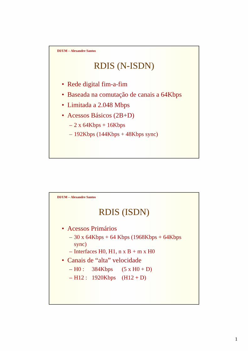
FRAME RELAY
3
DI/UM – Alexandre Santos
FRAME RELAY
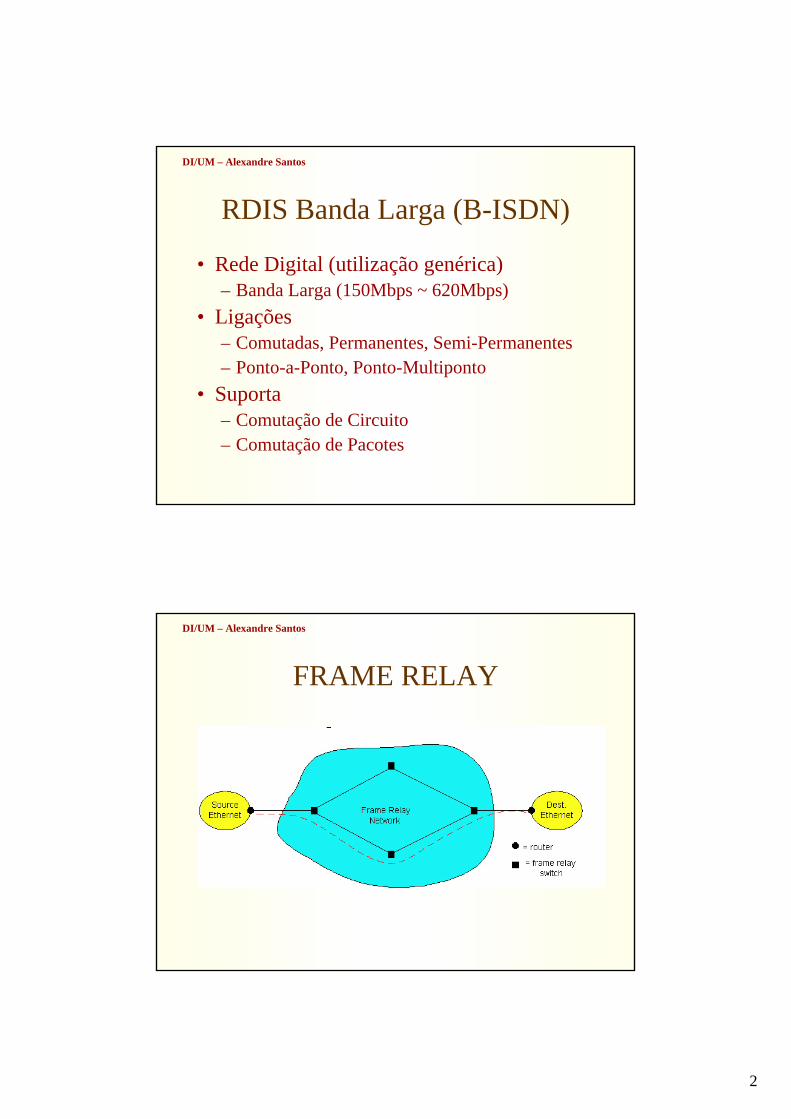
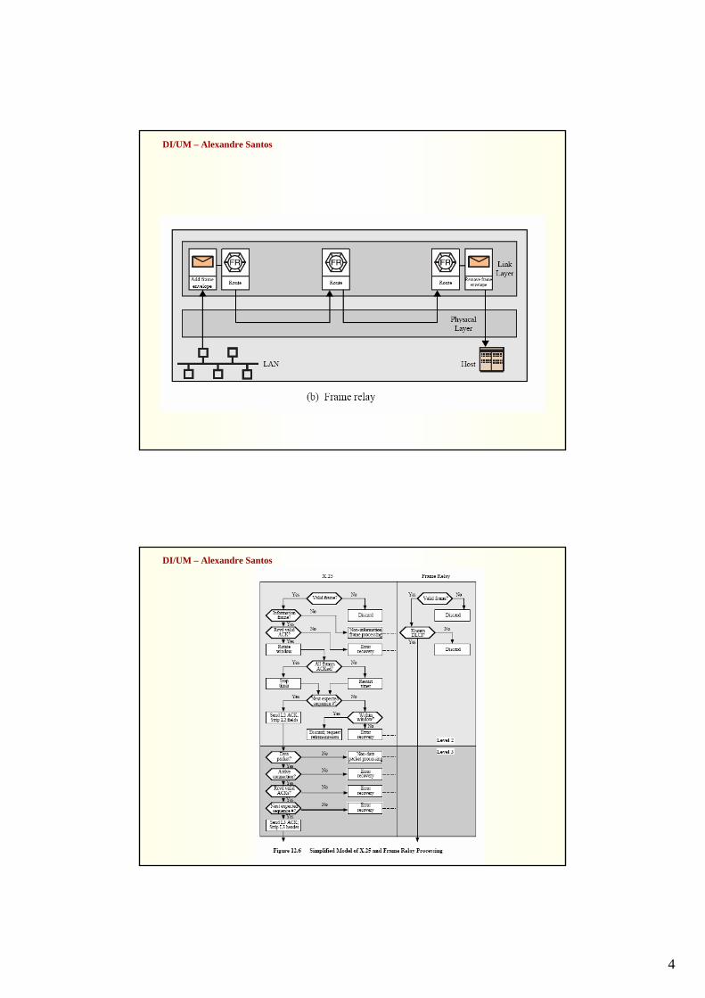
• “Herdeiro” do X.25.• O X.25 era caracterizado por:
– Comutação de pacotes– Pacotes de controlo inband– Multiplexagem de Circuitos Virtuais– Controlo de fluxo e de erros, tanto a Nível 2 como a
Nível 3– Elevada probabilidade de erros nos links (tecnologia
analógica)
DI/UM – Alexandre Santos
4
DI/UM – Alexandre Santos
DI/UM – Alexandre Santos
5
DI/UM – Alexandre Santos
DI/UM – Alexandre Santos
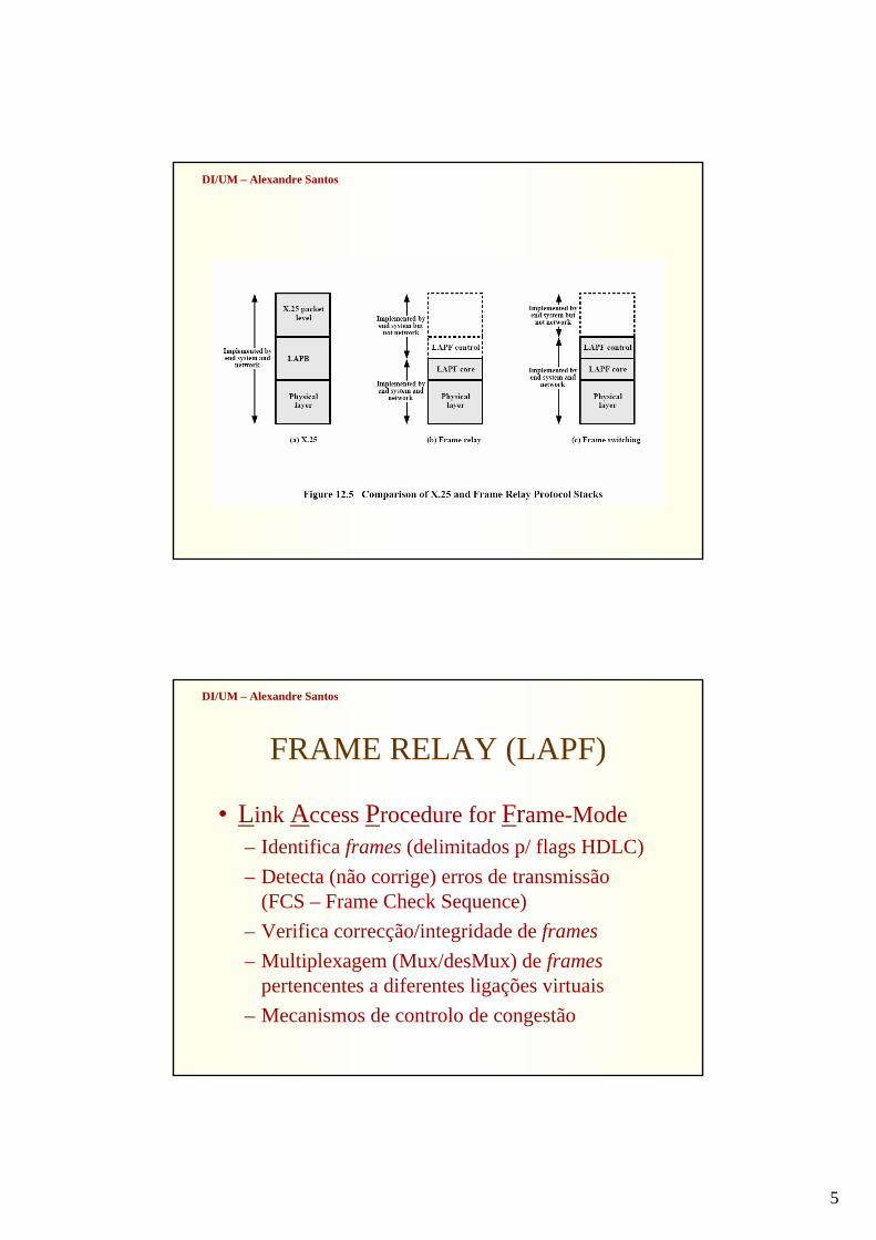
FRAME RELAY (LAPF)
• Link Access Procedure for Frame-Mode– Identifica frames (delimitados p/ flags HDLC)– Detecta (não corrige) erros de transmissão
(FCS – Frame Check Sequence)– Verifica correcção/integridade de frames– Multiplexagem (Mux/desMux) de frames
pertencentes a diferentes ligações virtuais– Mecanismos de controlo de congestão
6
DI/UM – Alexandre Santos
FRAME RELAY
• Sinalização de controlo out-of-band (ligaçãológica separada)
• Multiplexagem e comutação apenas a Nível 2• Eliminação de controlo de fluxo hop-a-hop• Controlo de fluxo e de erros apenas fim-a-fim• Baixa probabilidade de erros nos links (tecnologia
digital)
DI/UM – Alexandre Santos
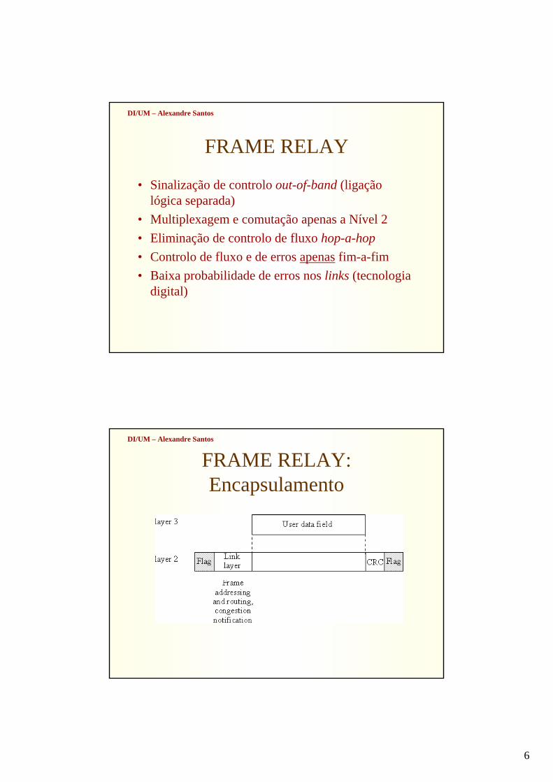
FRAME RELAY: Encapsulamento
7
DI/UM – Alexandre Santos
DI/UM – Alexandre Santos
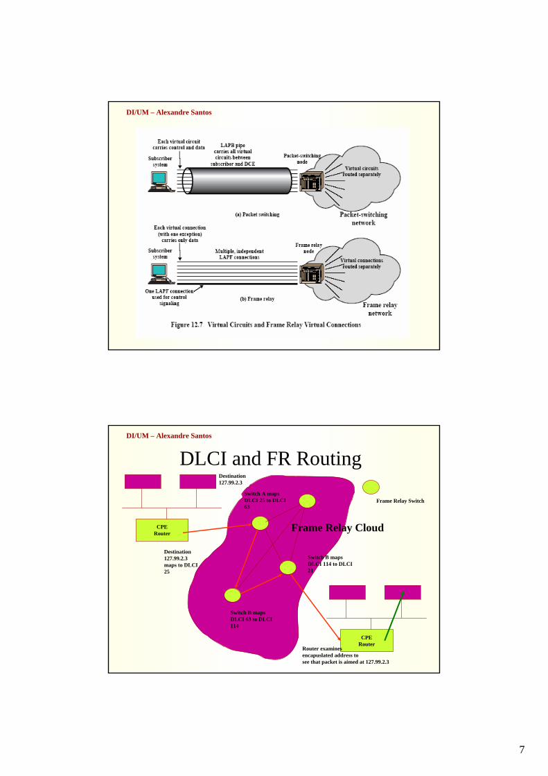
DLCI and FR Routing
CPERouter
CPERouter
Frame Relay Switch
Destination127.99.2.3
Destination127.99.2.3maps to DLCI25
Switch A mapsDLCI 25 to DLCI63
Switch B mapsDLCI 63 to DLCI114
Switch B mapsDLCI 114 to DLCI21
Router examinesencapuslated address tosee that packet is aimed at 127.99.2.3
Frame Relay Cloud
8
DI/UM – Alexandre Santos
DI/UM – Alexandre Santos
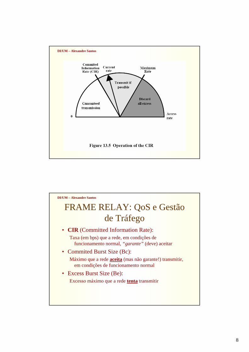
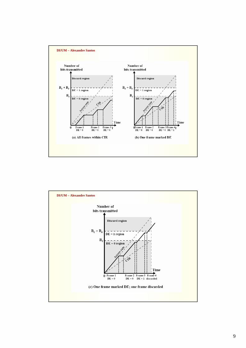
FRAME RELAY: QoS e Gestãode Tráfego
• CIR (Committed Information Rate): Taxa (em bps) que a rede, em condições de
funcionamento normal, “garante” (deve) aceitar
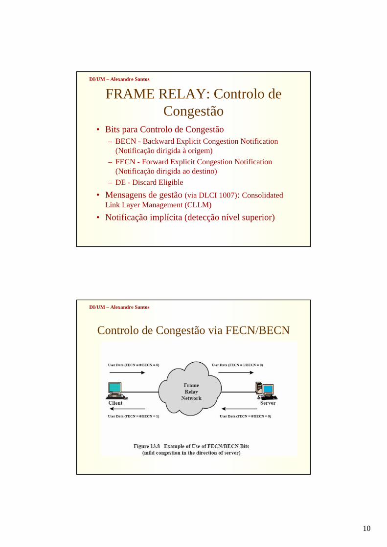
• Commited Burst Size (Bc): Máximo que a rede aceita (mas não garante!) transmitir,
em condições de funcionamento normal
• Excess Burst Size (Be): Excesso máximo que a rede tenta transmitir
9
DI/UM – Alexandre Santos
DI/UM – Alexandre Santos
10
DI/UM – Alexandre Santos
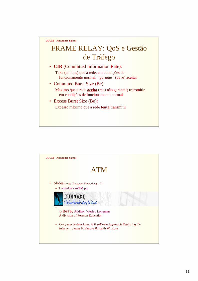
FRAME RELAY: Controlo de Congestão
• Bits para Controlo de Congestão– BECN - Backward Explicit Congestion Notification
(Notificação dirigida à origem)– FECN - Forward Explicit Congestion Notification
(Notificação dirigida ao destino)– DE - Discard Eligible
• Mensagens de gestão (via DLCI 1007): Consolidated Link Layer Management (CLLM)
• Notificação implícita (detecção nível superior)
DI/UM – Alexandre Santos
Controlo de Congestão via FECN/BECN
11
DI/UM – Alexandre Santos
FRAME RELAY: QoS e Gestãode Tráfego
• CIR (Committed Information Rate): Taxa (em bps) que a rede, em condições de
funcionamento normal, “garante” (deve) aceitar
• Commited Burst Size (Bc): Máximo que a rede aceita (mas não garante!) transmitir,
em condições de funcionamento normal
• Excess Burst Size (Be): Excesso máximo que a rede tenta transmitir
DI/UM – Alexandre Santos
ATM
• Slides (fonte “Computer Networking:…”):– Capítulo-5c-ATM.ppt
–© 1999 by Addison Wesley LongmanA division of Pearson Education
– Computer Networking: A Top-Down Approach Featuring theInternet; James F. Kurose & Keith W. Ross
12
© 1999 by Addison Wesley LongmanA division of Pearson Education
Asynchronous Transfer Mode: ATM
1980s/1990’s standard for high-speed (155Mbps to 622 Mbps and higher) Broadband Integrated Service Digital Network architectureGoal: integrated, end-end transport of carry voice, video, data
meeting timing/QoS requirements of voice, video (versus Internet best-effort model)“next generation” telephony: technical roots in telephone worldpacket-switching (fixed length packets, called “cells”) using virtual circuits
© 1999 by Addison Wesley LongmanA division of Pearson Education
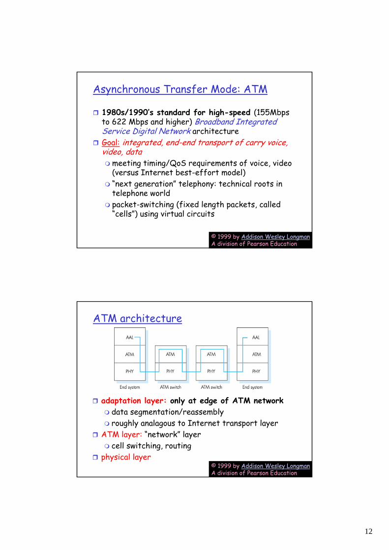
ATM architecture
adaptation layer: only at edge of ATM networkdata segmentation/reassemblyroughly analagous to Internet transport layer
ATM layer: “network” layercell switching, routing
physical layer
13
© 1999 by Addison Wesley LongmanA division of Pearson Education
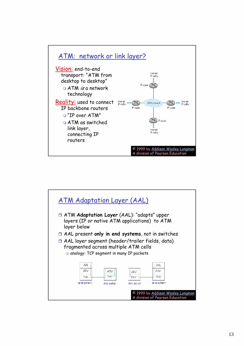
ATM: network or link layer?
Vision: end-to-end transport: “ATM from desktop to desktop”
ATM is a network technology
Reality: used to connect IP backbone routers
“IP over ATM”ATM as switched link layer, connecting IP routers
© 1999 by Addison Wesley LongmanA division of Pearson Education
ATM Adaptation Layer (AAL)
ATM Adaptation Layer (AAL): “adapts” upper layers (IP or native ATM applications) to ATM layer belowAAL present only in end systems, not in switchesAAL layer segment (header/trailer fields, data) fragmented across multiple ATM cells
analogy: TCP segment in many IP packets
14
© 1999 by Addison Wesley LongmanA division of Pearson Education
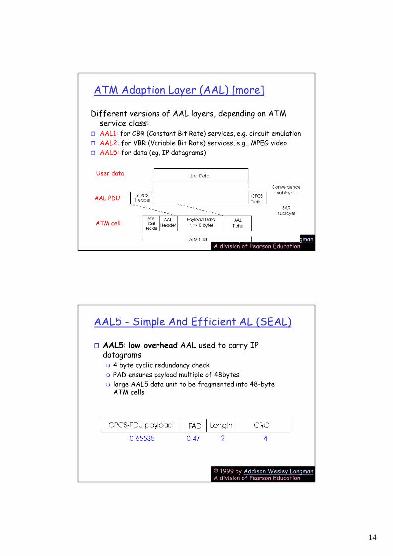
ATM Adaption Layer (AAL) [more]
Different versions of AAL layers, depending on ATM service class:AAL1: for CBR (Constant Bit Rate) services, e.g. circuit emulationAAL2: for VBR (Variable Bit Rate) services, e.g., MPEG videoAAL5: for data (eg, IP datagrams)
AAL PDU
ATM cell
User data
© 1999 by Addison Wesley LongmanA division of Pearson Education
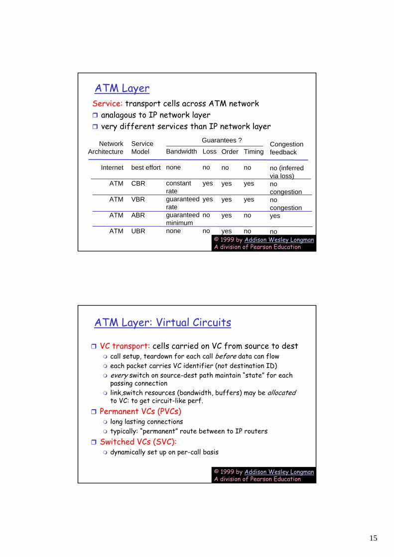
AAL5 - Simple And Efficient AL (SEAL)
AAL5: low overhead AAL used to carry IP datagrams
4 byte cyclic redundancy check PAD ensures payload multiple of 48bytes large AAL5 data unit to be fragmented into 48-byte ATM cells
15
© 1999 by Addison Wesley LongmanA division of Pearson Education
ATM LayerService: transport cells across ATM network
analagous to IP network layervery different services than IP network layer
NetworkArchitecture
Internet
ATM
ATM
ATM
ATM
ServiceModel
best effort
CBR
VBR
ABR
UBR
Bandwidth
none
constantrateguaranteedrateguaranteed minimumnone
Loss
no
yes
yes
no
no
Order
no
yes
yes
yes
yes
Timing
no
yes
yes
no
no
Congestionfeedback
no (inferredvia loss)nocongestionnocongestionyes
no
Guarantees ?
© 1999 by Addison Wesley LongmanA division of Pearson Education
ATM Layer: Virtual Circuits
VC transport: cells carried on VC from source to destcall setup, teardown for each call before data can floweach packet carries VC identifier (not destination ID)every switch on source-dest path maintain “state” for each passing connectionlink,switch resources (bandwidth, buffers) may be allocated to VC: to get circuit-like perf.
Permanent VCs (PVCs)long lasting connectionstypically: “permanent” route between to IP routers
Switched VCs (SVC):dynamically set up on per-call basis
16
© 1999 by Addison Wesley LongmanA division of Pearson Education
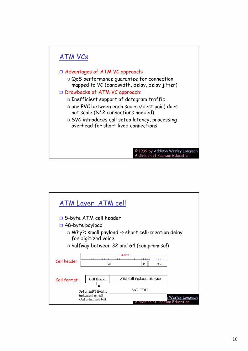
ATM VCs
Advantages of ATM VC approach:QoS performance guarantee for connection mapped to VC (bandwidth, delay, delay jitter)
Drawbacks of ATM VC approach:Inefficient support of datagram trafficone PVC between each source/dest pair) does not scale (N*2 connections needed) SVC introduces call setup latency, processing overhead for short lived connections
© 1999 by Addison Wesley LongmanA division of Pearson Education
ATM Layer: ATM cell
5-byte ATM cell header48-byte payload
Why?: small payload -> short cell-creation delay for digitized voicehalfway between 32 and 64 (compromise!)
Cell header
Cell format
17
© 1999 by Addison Wesley LongmanA division of Pearson Education
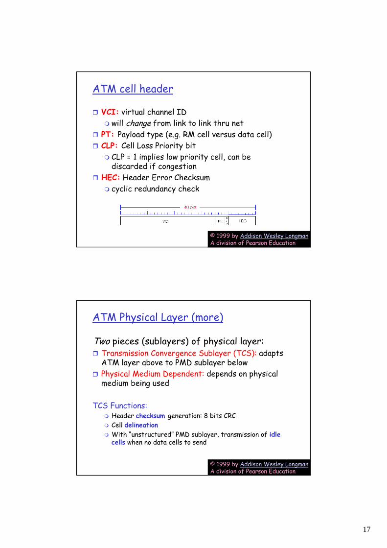
ATM cell header
VCI: virtual channel IDwill change from link to link thru net
PT: Payload type (e.g. RM cell versus data cell) CLP: Cell Loss Priority bit
CLP = 1 implies low priority cell, can be discarded if congestion
HEC: Header Error Checksumcyclic redundancy check
© 1999 by Addison Wesley LongmanA division of Pearson Education
ATM Physical Layer (more)
Two pieces (sublayers) of physical layer:Transmission Convergence Sublayer (TCS): adapts ATM layer above to PMD sublayer belowPhysical Medium Dependent: depends on physical medium being used
TCS Functions:Header checksum generation: 8 bits CRC Cell delineationWith “unstructured” PMD sublayer, transmission of idle cells when no data cells to send
18
© 1999 by Addison Wesley LongmanA division of Pearson Education
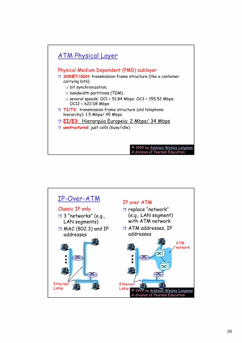
ATM Physical Layer
Physical Medium Dependent (PMD) sublayerSONET/SDH: transmission frame structure (like a container carrying bits);
bit synchronization; bandwidth partitions (TDM); several speeds: OC1 = 51.84 Mbps; OC3 = 155.52 Mbps; OC12 = 622.08 Mbps
TI/T3: transmission frame structure (old telephone hierarchy): 1.5 Mbps/ 45 MbpsEI/E3: Hierarquia Europeia: 2 Mbps/ 34 Mbpsunstructured: just cells (busy/idle)
© 1999 by Addison Wesley LongmanA division of Pearson Education
IP-Over-ATMClassic IP only
3 “networks” (e.g., LAN segments)MAC (802.3) and IP addresses
IP over ATMreplace “network” (e.g., LAN segment) with ATM networkATM addresses, IP addresses
ATMnetwork
EthernetLANs
EthernetLANs
19
© 1999 by Addison Wesley LongmanA division of Pearson Education
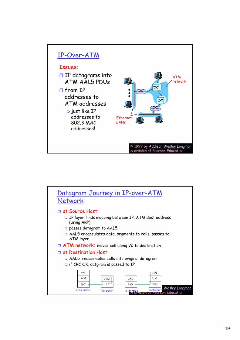
IP-Over-ATM
Issues:IP datagrams into ATM AAL5 PDUsfrom IP addresses to ATM addresses
just like IP addresses to 802.3 MAC addresses!
ATMnetwork
EthernetLANs
© 1999 by Addison Wesley LongmanA division of Pearson Education
Datagram Journey in IP-over-ATM Network
at Source Host:IP layer finds mapping between IP, ATM dest address (using ARP)passes datagram to AAL5AAL5 encapsulates data, segments to cells, passes to ATM layer
ATM network: moves cell along VC to destinationat Destination Host:
AAL5 reassembles cells into original datagramif CRC OK, datgram is passed to IP
20
© 1999 by Addison Wesley LongmanA division of Pearson Education
ARP in ATM Nets
ATM network needs destination ATM addressjust like Ethernet needs destination Ethernet address
IP/ATM address translation done by ATM ARP (Address Resolution Protocol)
ARP server in ATM network performs broadcast of ATM ARP translation request to all connected ATM deviceshosts can register their ATM addresses with server to avoid lookup
DI/UM – Alexandre Santos
ATM
• Exemplo para análise
• Exemplo na Univ. Minho
21
DI/UM – Alexandre Santos
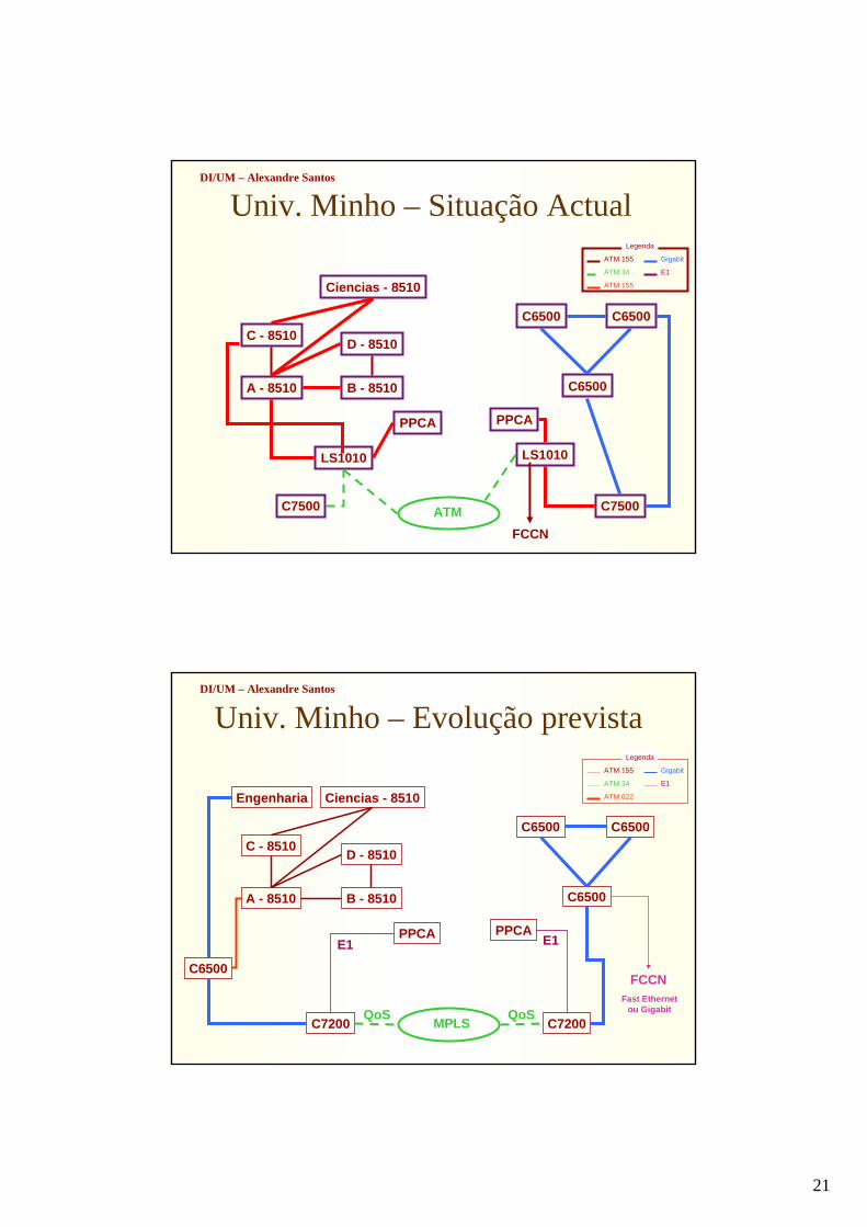
Univ. Minho – Situação Actual
C - 8510
B - 8510
D - 8510
A - 8510
Ciencias - 8510
LS1010
C7500
PPCA
ATM
LS1010
C7500
C6500
C6500 C6500
PPCA
FCCN
ATM 155
ATM 34
ATM 155
E1
Gigabit
Legenda
DI/UM – Alexandre Santos
Univ. Minho – Evolução prevista
C - 8510
B - 8510
D - 8510
A - 8510
Engenharia Ciencias - 8510
PPCA
C6500
MPLS
C6500
C6500 C6500
PPCA
FCCN
QoSFast Ethernet
ou GigabitQoS
E1 E1
C7200 C7200
ATM 155
ATM 34
ATM 622
E1
Gigabit
Legenda
22
DI/UM – Alexandre Santos
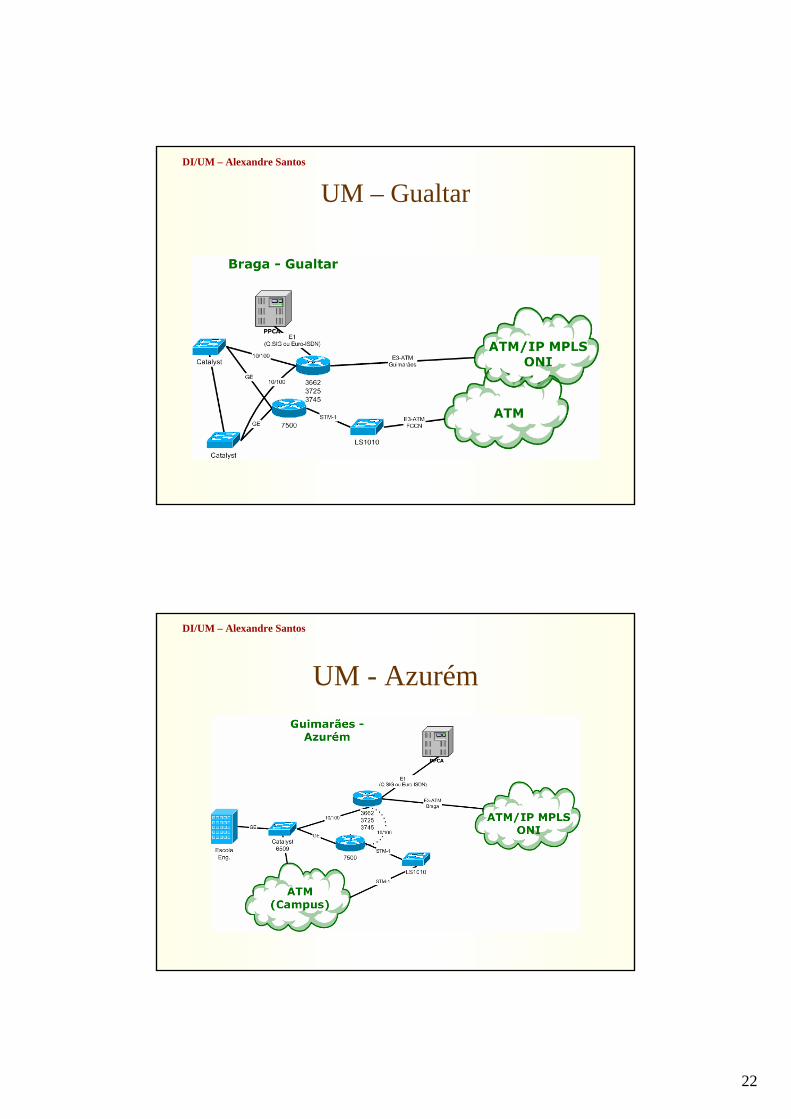
UM – Gualtar
DI/UM – Alexandre Santos
UM - Azurém
23
DI/UM – Alexandre Santos
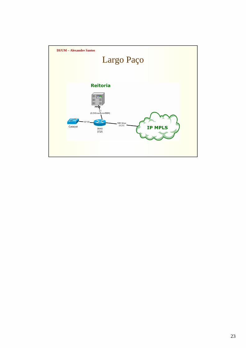
Largo Paço
![Redes opticas [Modo de Compatibilidade] - MAURO … · também capacidades de transmissão maiores. ... (SONET/SDH e IP ). – Uniformidade de serviços (voz e dados com poucas interface](https://img.document.onl/doc/110x75/5b6373a37f8b9af84b8bf011/redes-opticas-modo-de-compatibilidade-mauro-tambem-capacidades-de-transmissao.jpg)