Embed Size (px)
Citation preview

Fire resistance behaviour of GFRP
pultruded profiles
Tiago Miguel Rodrigues Morgado
Extended abstract
Jury:
President: Professor Doutor Jorge Manuel Caliço Lopes de Brito
Supervisor: Professor Doutor João Pedro Ramôa Correia
Co-supervisor: Professor Doutor Fernando António Baptista Branco
Examiner: Professor Doutor João Paulo Janeiro Gomes Ferreira
Examiner: Professora Doutora Inês dos Santos Flores Barbosa Colen
November 2012


Page 1 of 16
FIRE RESISTANCE BEHAVIOUR OF GFRP PULTRUDED
PROFILES
Tiago Miguel Rodrigues Morgado
Instituto Superior Técnico, Technical University of Lisbon
Abstract: This paper presents experimental investigations on the behaviour of GFRP pultruded
profiles exposed to fire. The feasibility and efficacy of using five different materials to provide
fire protection to GFRP pultruded profiles were investigated. The experimental programme
included differential scanning calorimetry and thermogravimetric analysis (DSC/TGA)
experiments and fire resistance tests on GFRP tubular loaded beams. Fire resistance tests
included different types of exposition to fire, regarding the number of surfaces exposed to heat,
and different loading levels. The unprotected GFRP beam, exposed to fire only in one surface
and subjected to a load corresponding to a midspan deflection of L/400, failed after about
36 min, while the five different passive protection systems provided a fire resistance between
51-83 min. The unprotected GFRP beam and one protected GFRP beam, exposed in three
surfaces and subjected to the same service load, failed after about 8 and 46 min, respectively.
An unprotected GFRP beam and one protected GFRP beam, exposed only in one surface and
subjected to a load corresponding to a midspan deflection of L/250, failed after about 31 and
66 min, respectively. Failure occurred mostly in the upper part of the beams, due to
compression and shear stresses.
Key-words: Glass fiber reinforced polymer pultruded profiles (GFRP), composite materials,
experimental tests, behaviour of GFRP beams in a fire situation, fire protection systems.
1. Introduction
The most currently used material in civil engineering applications is reinforced concrete, which
exploits the best features of steel and concrete materials. Fiber reinforced polymer (FRP)
materials are being increasingly used in civil engineering applications due to their several
advantages when compared to traditional materials, namely, the lightness, strength, good
insulation properties, low maintenance and durability. At the same time, new design issues and
challenges are inevitable encountered, among which are the legitimate concerns their
performance when exposed to fire, especially in building applications [1].
When fiber reinforced polymer materials are exposed to moderate temperatures (100-200 ºC),
FRP materials soften, creep and distort, and such degradation of mechanical properties often
leads to buckling failure mechanisms of load-bearing composite structures. When these
materials are exposed to high temperatures (300-500 ºC), the organic matrix decomposes,
releasing heat, smoke, soot and toxic volatiles [2]. Glass is the most widely used reinforcement
in FRP materials. For E-glass fibers, which are presently used in 80-90% of the commercially
available FRP materials [3], softening and viscous flow start only when temperatures reach
about 830 ºC, and melting occurs at about 1070 ºC [4].
Construction materials used in buildings are required to have adequate fire reaction behaviour,
avoiding fire ignition, flame spreading and excessive smoke production and spreading.
Additionally, structural elements are also expected to present sufficient fire resistance in order
to prevent structural collapse under fire. Although these composite materials do not present

Fire resistance behaviour of GFRP pultruded profiles
Page 2 of 16
adequate fire reaction behaviour, composites are very good heat insulators, and this feature is
important for slowing the spread of fire from room to room. Also when compared to steel,
composites present better burn-through resistance, providing an effective barrier against flame,
heat, smoke and toxic fumes. Furthermore, several measures can be applied to improve the fire
performance of FRP materials [5].
Experiments reported by Wong et al. on the compressive strength of GFRP columns at high
temperatures showed noticeable strength reductions already at 60 ºC and 90 ºC, with
compressive strengths at those temperatures being 63% and 31%, respectively, of the ambient
temperature strength [6].
Correia [7] investigated the behaviour of GFRP pultruded square tubular profiles exposed to
fire. An unprotected GFRP beam, exposed only in one surface, failed after about 38 min, the
three different passive protection systems provided a fire resistance between 65-76 min and the
water cooling system provided a fire resistance of at least 120 min. In these tests the failure
occurred in the upper part of the beams, due to compression and shear stresses.
Massot [8] investigated the behaviour of GFRP floors exposed to fire. An especially designed
full scale test has been carried out on three beams laid adjacently to each other, loaded to rated
stress during fire in three points bending. For comparison purpose, an equivalent steel flooring
has been installed on the same oven, also loaded centrally to the same level. Load on the steel
flooring has been withdrawn after about 15 min, due to slow sinking of the plate in fire. After
that, steel flooring continued to sink under own weight. On the contrary, composite flooring
sustained load all along the test which was stopped after 41 min, when smoke and flames began
to propagate between beams.
The main objective of the experimental programme reported herein was to evaluate the fire
resistance of GFRP beams and to evaluate the feasibility of different fire protection systems.
The experiments were divided into three experimental series. In the first series seven beams
were tested, two of them unprotected and five with fire protection systems, being exposed to fire
only in one surface and subjected to a load corresponding to a midspan deflection of L/400. The
second experimental series included three beams, two unprotected and one fire protected, all
exposed in three surfaces and subjected to the same service load. The third series comprised two
beams, one unprotected and the other with fire protection, both exposed to fire only in one
surface and subjected to a service load corresponding to a midspan deflection of L/250.
Differential scanning calorimetry and thermogravimetric analysis (DSC/TGA) tests were also
performed. The DSC/TGA tests were performed to study the thermo-physical behaviour of both
GFRP and fire protections materials at elevated temperature.
2. Materials
The GFRP material used in the fire experiments consisted of tubular pultruded profiles
(100×100×8 mm) supplied and produced by Fiberline. This material is constituted by alternating
layers of unidirectional E-glass fibre rovings and strand mats (69% in weight) embedded in an
isophthalic polyester resin matrix. A dissection of a profile’s laminate showed that the rovings
are positioned in the centre of the cross-section, while two mats are positioned next to the
surface of the material, having continuity in the web-flange junctions.

Fire resistance behaviour of GFRP pultruded profiles
Page 3 of 16
Five different materials to be used as passive fire protection systems for GFRP pultruded
profiles were investigated, namely, an agglomerated cork (AC) board, a rockwool (RW) board,
a calcium silicate (SC) board, an intumescent mat (TEC) and an intumescent coating (TI). The
AC board, produced by Robcork, is made of agglomerated cork. The RW board used in the
experiments was produced by Rockwool and is constituted primarily by rock wool. The SC
board, produced by Promatec (Type H), is made of agglomerated calcium silicate. The
intumescent mat used in experiments (Tecnofire 60853A, thickness of 2 mm) was supplied by
Technical Fibre Products Lda. The intumescent coating (C-THERM HB) was supplied by CIN.
2.1. DSC/TGA experiments
Differential scanning calorimetry (DSC) and thermogravimetric analysis (TGA) measurements
were performed on the GFRP pultruded material and on the fire protection materials, in order to
determine the mass variation and the energy changes as a function of temperature. These
experiments allowed determining, in particular, the decomposition temperature of the polymer,
Td. Experiments were performed at the Chemical Engineering Department of IST. Tests were
run from a temperature of 30 ºC to about 800 ºC, in both air and nitrogen atmospheres, at
heating rates of 5, 10, 15 and 20 ºC/min. Table 1 lists the experimental programme performed to
study the thermo-physical behaviour of both GFRP and fire protection materials at high
temperature.
Table 1: DSC/TGA experiments.
Material Purge gas Heating rate [ºC/min]
GFRP Air/Nitrogen 5, 10, 15 and 20 (in each atmosphere)
AC Air/Nitrogen 10 (in each atmosphere)
RW Air/Nitrogen 10 (in each atmosphere)
SC Air/Nitrogen 10 (in each atmosphere)
TEC Air/Nitrogen 10 (in each atmosphere)
TI Air/Nitrogen 10 (in each atmosphere)
Results obtained from TGA measurements in air (GFRP-O) and nitrogen (GFRP-N)
atmospheres are presented in Figure 1 (for the GFRP material) and allowed defining the
decomposition temperature of the GFRP material at 370 ºC, based on the middle temperature of
the sigmoidal mass change.
Figure 1: DSC/TGA results in GFRP material: loss mass vs. temperature and
heat flow/mass vs. temperature (O – Air; N – Nitrogen).

Fire resistance behaviour of GFRP pultruded profiles
Page 4 of 16
The fire protection materials results obtained from TGA experiments in both atmospheres are
presented in Figure 2. It can be seen that agglomerated cork presented a considerable mass loss,
which is accompanied by the release of heat. Oppositely, rockwool presented a small mass loss
releasing a small heat flow as well. Attending to TGA experiments, rockwool and calcium
silicate were the two materials with better fire behaviour.
Figure 2: DSC/TGA results in fire protection materials: loss mass vs. temperature and
heat flow/mass vs. temperature (O – Air; N - Nitrogen).
3. Fire resistance test setup
3.1. Objectives
Fire resistance tests were performed on loaded GFRP pultruded beams under a fire situation,
either unprotected and protected with different fire protection systems, in order to determine the
thermal response, the mechanical response, the failure modes and the fire resistance of the
different systems. In particular, one aimed at evaluating the effects (i) applying fire protection
materials, (ii) exposing the GFRP beams to 1 or 3 surfaces, and (iii) applying different load
levels.
3.2. Experimental programme
Fire experiments were conducted in an oven and the experiments were divided into three
experimental series. In the first series seven beams were tested, two of them unprotected and
five with fire protection, being exposed to fire only in one surface (the bottom one) and
subjected to a load corresponding to a midspan deflection of L/400. The second experimental
series included three beams, two unprotected and one fire protected, all exposed in three
surfaces (the bottom and the lateral) and subjected to the same service load. The third series was
composed by two beams, one unprotected and the other with fire protection, both exposed to
fire only in one surface and subjected to a service load corresponding to a midspan deflection of
L/250. The five passive fire protection systems were applied on one surface (series 1 and 3) or
three surfaces (series 2) and consisted of: (i) a 25 mm thick AC board (beam AC); (ii) a 25 mm
thick RW board (beam RW); (iii) a 25 mm thick SC board (beams SC); (iv) a 2 mm thick
intumescent mat layer (beam TEC); and (v) a 2 mm thick intumescent coating layer (beam TI).
Table 2 presents the experimental programme performed.

Fire resistance behaviour of GFRP pultruded profiles
Page 5 of 16
The experimental programme included five unprotected beams, two of them with a cap (NPCT)
and three without a cap (NPST). The cap was made in order to properly install thermocouples
into the bottom and the lateral surfaces of the GFRP tubes. These beams (NPCT) were used
only to measure temperatures, as they were not subjected to mechanical load.
Table 2: Overview of fire resistance experiments.
Experimental
series
Specimen
labelling Fire protection
Fire
exposure
Loading
level
Series 1
NPCT-1F -
1 surface
-
NPST-1F -
L/400
AC-1F Agglomerated cork
RW-1F Rockwool
SC-1F Calcium silicate
TEC-1F Intumescent blanket
TI-1F Intumescent coating
Series 2
NPCT-3F -
3 surfaces
-
NPST-3F - L/400
SC-3F Calcium silicate
Series 3 NPST-1F -
1 surface L/250 SC-1F Calcium silicate
3.3. Specimen preparation
The preparation of the test specimens was carried out at IST and consisted of three main tasks:
(i) cutting the GFRP profiles into the intended length (1,6 m); (ii) drilling holes at
predetermined locations in the GFRP profile for installation of thermocouples; and (iii)
application of the fire protection systems. In order to install the thermocouples for the
measurement of temperature profiles throughout the GFRP tubes, 2,0 mm diameter holes were
drilled at predetermined sections and depths in the tested beams at midspan section (see Figure
3). The thermocouples were then fixed with a polyester resin.
Figure 3: Fire resistance tests setup – instrumentation at midspan section: (a) unprotected beams (series 1
and 3); (b) unprotected beam (series 2); (c) protected beams with protections systems (series 1, 2 and 3).
Figure 4 illustrates the thermocouples installation process in unprotected beams
(NPCT (series 1) and NPCT (series 2)). In the unprotected beam from series 1 one cover was
installed in the top surface, while in the unprotected beam from series 2 two covers had to be
installed in the top surface and in one of the lateral surfaces.

Fire resistance behaviour of GFRP pultruded profiles
Page 6 of 16
Figure 4: NPCT (series 1) beams preparation: (a) removal of cover and (b) thermocouples installation
process in bottom surface; NPCT (series 2) beams preparation: (c) thermocouples installation process in lateral and bottom surfaces and (d) sealing of the lateral cover.
Figure 5 illustrates the thermocouples installation process in protected and unprotected (NPST)
beams.
Figure 5: Thermocouples installation process in (a) upper, (b) lateral and (c) bottom surfaces in protected
and unprotected beams.
For the preparation of beams AC and SC, the AC and SC boards were fixed to the GFRP
surfaces using a fire resistant mastic combined with mechanical system comprising thin metal
handless. For the preparation of beam RW, the RW board was fixed to the GFRP surface using
a mortar supplied by Rockwool. Figure 6 illustrates the preparation of these beams.
Figure 6: Preparation of beams (a) AC, (b) RW, (c) SC (series 1 and 3) and (d) SC (series 2).
For the preparation of beam TEC, the intumescent mat was cut with scissors and fixed to the
GFRP surface using polyester resin (produced by Polyfix). For the preparation of beam TI,
successive layers of intumescent coating were applied until the intended thickness of 2 mm was
attained. Figure 7 illustrates the preparation of these beams.

Fire resistance behaviour of GFRP pultruded profiles
Page 7 of 16
Figure 7: Preparation of beams (a) and (b) TEC and (c) TI.
3.4. Test setup, instrumentation and procedure
3.4.1. Oven
Fire resistance experiments were performed on a vertical oven, with external dimensions of
1,35 m long × 1,20 m wide × 2,10 m high, that presents an opening on the top surface to test
horizontal elements (Figure 10). The oven is fired by six gas burners controlled by a computer,
which reads the oven temperature from three internal thermocouples and is able to adjust the
burners’ intensity in order to follow, as close as possible, a predefined time-temperature curve.
3.4.2. Fire loading
Fire resistance tests were performed with the fire exposure according to the ISO 834 [9]
time-temperature curve, which is described by the following equation,
)18(log345)( 10 tTtT o (1)
where T (in ºC) is the oven temperature, t (in minutes) is the time and T0 (also in ºC) is the
initial oven temperature.
3.4.3. Test setup
In series 1 and 3, the tested GFRP profiles were placed over the opened top of the oven,
positioned along its length. The top of the oven was covered with four modules, placed
adjacently to the lateral surfaces of the GFRP profiles, as shown in Figure 8. Consequently, the
lateral surfaces were protected from being directly exposed to the furnace heat and only the
bottom surfaces of the profiles were directly exposed to heat.
Figure 8: The top cover of the oven in series 1 and 3 (lateral view).

Fire resistance behaviour of GFRP pultruded profiles
Page 8 of 16
The GFRP beams were supported on roller supports (12 cm long × 6 cm wide) placed over
metallic plates, adjacently to the oven’s external walls. Beams were installed keeping a vertical
distance of 5 cm between their bottom surface and the oven’s lateral walls, in order to allow for
the deformation of the beams during the tests, without touching the oven’s walls, which was
guaranteed in all tests.
In series 2, the top of the oven was covered with four modules, two of them in a high level,
exposing the lateral surfaces of the GFRP profiles directly to the oven heat. Figure 9 illustrates
the mentioned top cover of the oven used in the tests of series 2.
Figure 9: The top cover of the oven in series 2 (lateral view).
3.4.4. Structural loading
The GFRP beams, with a length of 1,60 m, were tested in four-point bending in a 1,30 m span.
In series 1 and 2, a total load of 11,7 kN was applied in two sections, as shown in Figure 10,
while in series 3 a total load of 18,7 kN was applied. Load was applied by means of concrete
elements, suspended in a load transmission steel beam with pulley blocks, which facilitated the
operations of loading/unloading. The applied loads of 11,7 and 18,7 kN, constant in all tests,
corresponds to the serviceability load, for midspan deflections of L/400 and L/250, respectively,
L being the span.
3.4.5. Instrumentation
One displacement transducers from TML (model CDP-500, with 500 mm stroke and precision
of 0.01 mm), was used to measure deflections at midspan section, at the centre of the top
surface. The beams were instrumented with sets of thermocouples type K, with twin wires
enfolded by a thick glass fabric. As previously referred, the thermocouples were placed on holes
drilled at predetermined depths and heights inside the GFRP profile. Temperatures throughout
the top surface were measured with thermocouples T1–T3, placed at the depths of 2,0 mm (T1),
4,0 mm (T2) and 6,0 mm (T3), as shown in Figure 3. Throughout the lateral surface,
temperatures were measured at a depth of 4,0 mm inside the material with thermocouples
T4-T6, uniformly distributed across the height of the lateral surface. In the bottom surface of
unprotected beams (NPCT), temperatures were measured with thermocouples T7 (at a depth of
1 mm), T8 (3,0 mm), T9 (5,0 mm) and T10 (7,0 mm). In the bottom surface of protected beams,

Fire resistance behaviour of GFRP pultruded profiles
Page 9 of 16
temperatures were measured with thermocouples T7 (at a depth of 0,5 mm), T8 (2,0 mm), T9
(4,0 mm), T10 (6,0 mm) and T11 (7,5 mm).
Figure 10: Fire resistance tests setup – frontal view (dimensions in meters).
3.4.6. Test procedure
With the exception of unloaded beams, all tests started with the application of the structural
loading. Following a recommendation of ISO 834 [9], measurements were performed for a
period of 10 min without starting the fire exposure, in order to guarantee a stabilisation of
deflections and deformations. The fire exposure started with the ignition of the burners, after
which specimens started to be thermally loaded according to ISO 834 time-temperature curve.
Specimens were thermally loaded up to structural collapse or up to a duration of 60 min in
beams NPCT.
4. Fire resistance test results
4.1. Temperature profiles
4.1.1. Series 1
In the first series, to help comparing the fire resistance test results, average temperatures (T-m)
for each surface were determined for all beams. Figures 11 and 12 show average the
temperatures measured as a function of time at different depths inside the GFRP profile at the
upper and lateral surfaces of midspan section, for both unprotected and protected GFRP
profiles. Figure 12 also shows the progression of temperature of the air inside the oven for all
tests of series 1.
Fire resistance behaviour of GFRP pultruded profiles
Page 10 of 16
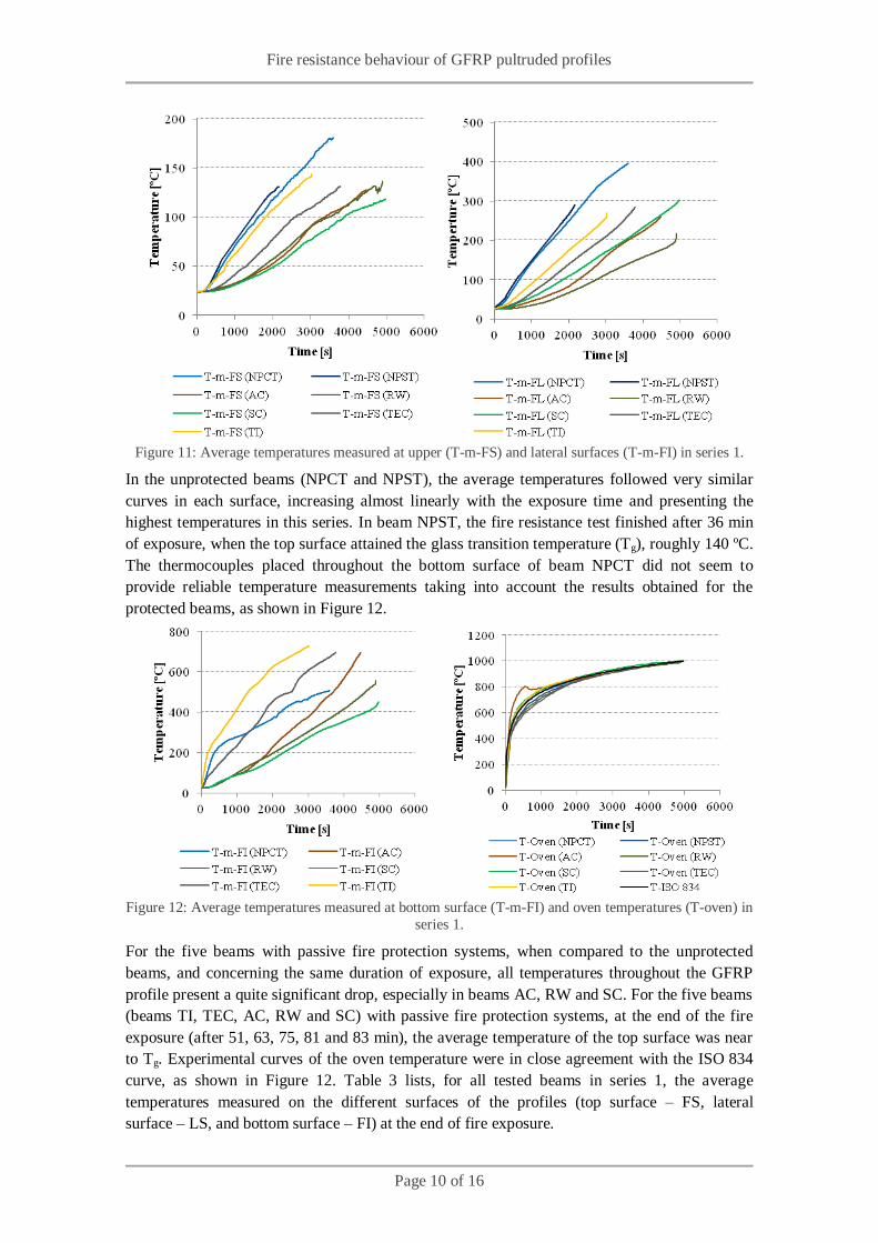
Figure 11: Average temperatures measured at upper (T-m-FS) and lateral surfaces (T-m-FI) in series 1.
In the unprotected beams (NPCT and NPST), the average temperatures followed very similar
curves in each surface, increasing almost linearly with the exposure time and presenting the
highest temperatures in this series. In beam NPST, the fire resistance test finished after 36 min
of exposure, when the top surface attained the glass transition temperature (Tg), roughly 140 ºC.
The thermocouples placed throughout the bottom surface of beam NPCT did not seem to
provide reliable temperature measurements taking into account the results obtained for the
protected beams, as shown in Figure 12.
Figure 12: Average temperatures measured at bottom surface (T-m-FI) and oven temperatures (T-oven) in
series 1.
For the five beams with passive fire protection systems, when compared to the unprotected
beams, and concerning the same duration of exposure, all temperatures throughout the GFRP
profile present a quite significant drop, especially in beams AC, RW and SC. For the five beams
(beams TI, TEC, AC, RW and SC) with passive fire protection systems, at the end of the fire
exposure (after 51, 63, 75, 81 and 83 min), the average temperature of the top surface was near
to Tg. Experimental curves of the oven temperature were in close agreement with the ISO 834
curve, as shown in Figure 12. Table 3 lists, for all tested beams in series 1, the average
temperatures measured on the different surfaces of the profiles (top surface – FS, lateral
surface – LS, and bottom surface – FI) at the end of fire exposure.

Fire resistance behaviour of GFRP pultruded profiles
Page 11 of 16
Table 3: Average temperatures at the end of fire exposure in each surface.
Beam Average temperatures at the end of fire exposure
Failure mode T-m-FS [ºC] T-m-FL [ºC] T-m-FI [ºC]
NPST 131 289 - Compressive
failure of the
top surface and shear failure of
lateral surfaces.
AC 128 259 695
RW 136 217 557
SC 118 302 452
TEC 131 284 697
TI 145 272 727
4.1.2. Series 2
In the second series, to compare the fire resistance test results, average temperatures (T-m) for
each surface were also determined, as mentioned previously. Figure 13 shows the temperatures
measured at different depths inside the GFRP profile in midspan, as function of time, for both
the unprotected and the protected GFRP profiles.
Figure 13: Average temperatures measured at upper (T-m-FS), lateral (T-m-FL) and bottom (T-m-FI)
surfaces and oven temperatures (T-oven) in series 2.
In unprotected beam (NPCT), the average temperatures in both lateral and bottom surfaces
followed very similar curves. In beam NPST, the fire resistance test finished after only 8 min of
exposure. In this beam, the temperature measurements were not reliable, and were therefore
discarded.
For the beam with passive fire protection system (beam SC), when compared to the unprotected
beam (beam NPCT), all thermocouples throughout the GFRP profile presented a quite
significant drop. In this protected beam, the fire resistance test finished after 46 min. In series 2,
oven temperatures also followed those defined in the ISO 834 curve, as shown in Figure 13.
4.1.3. Series 3
In the third series, the average temperatures (T-m) for each surface were also determined, in
order to compare the fire resistance test results. Figure 14 shows the temperatures measured at
different depths inside the GFRP profile at midspan, as function of time, for both the
unprotected and the protected GFRP profiles.

Fire resistance behaviour of GFRP pultruded profiles
Page 12 of 16
Figure 14: Average temperatures measured at upper (T-m-FS), lateral (T-m-FL) and bottom (T-m-FI)
surfaces and oven temperatures (T-oven) in series 3.
For the beam with passive fire protection (beam SC), when compared to the unprotected beam
(beam NPST), all thermocouples throughout the GFRP profile presented a quite significant
drop. In beams NPST and SC, the fire resistance tests finished after 31 and 66 min, respectively.
4.2. Mechanical behaviour
4.2.1. Series 1
Figure 15 presents midspan deflections of all beams tested in series 1 as a function of time.
Before fire exposure started, midspan deflection of the beams varied between 3,3 and 4,1 mm,
which corresponds roughly to L/400 of the span (3,25 mm).
Figure 15: Midspan deflection vs. time in series 1.
Figure 15 shows that during the first 30 s after burner ignition, midspan deflection of beam
NPST remained constant. After 30 s of fire exposure, the unprotected beam suffered a rapid
increase. However, only the beginning of the midspan deflection of beam NPST could be
measured due to a problem in the connection of the displacement transducer to the data logger.
In the beams protected with passive systems, during most of the time of the tests, midspan
deflection increased almost linearly with the exposure time, at variable rates among the different
beams. At the end of the fire exposure, midspan deflection of protected beams suffered a rapid
increase, as shown in Figure 15.

Fire resistance behaviour of GFRP pultruded profiles
Page 13 of 16
4.2.2. Series 2
Figure 16 presents midspan deflections as a function of time of beams tested in series 2,
together with corresponding ones from series 1 to allow for a comparison between them. Before
fire exposure started, midspan deflection of the beams varied between 2,5 and 3,6 mm, which
corresponds roughly to L/400 of the span (3,25 mm).
Figure 16: Midspan deflection vs. time in series 1 and 2.
In beam NPST (series 2), after 20 s of fire exposure, the midspan deflection of the unprotected
beam suffered a rapid increase, presenting a midspan deflection at a quicker rate comparing to
beam NPST (series 1). For beam SC, midspan increase was similar for beams from
series 1 and 2, most probably because unlike beam NPST from series 2, the lateral surfaces of
beam from series 1 were thermally insulated.
4.2.3. Series 3
Figure 17 presents midspan deflections as a function of time of beams tested in series. Results
obtained for corresponding beams from series 1 are also plotted to allow for a direct
comparison. Before fire exposure started, midspan deflection of the beams varied between 6,3
and 6,8 mm, which is slightly higher than L/250 of the span (5,2 mm).
Figure 17: Midspan deflection vs. time in series 1 and 3.
In beam NPST (series 3), after 60 s of fire exposure, midspan deflection of the unprotected
beam suffered a rapid increase, presenting a faster midspan deflection increase comparing to
beam NPST (series 1). Beam SC (series 3) presented similar deflection increase compared to

Fire resistance behaviour of GFRP pultruded profiles
Page 14 of 16
beam SC (series 1) during most of the exposure, exhibiting only a much higher deflection
variation at the end of its test.
4.3. Failure modes and post-fire assessment
All tested beams collapsed without any prior warning signs. The unprotected beam, exposed to
fire in three surfaces, collapsed as a consequence of the resin softening in the lateral surfaces
and presenting also a crack at the top surface, as shown in Figure 18.
Figure 18: Beam NPST (series 2): (a) resin softening in lateral surfaces and (b) top surface cracked.
The remaining beams collapsed due to compressive failure of the top surfaces and to shear
failure of the lateral ones, as shown in Figure 19.
Figure 19: Beams collapsed due (a) to compressive failure of top surfaces and (b) to shear failure of
lateral surfaces.
5. Discussion
5.1. Thermo-mechanical response
The evolution of both deflections and deformations is intrinsically related to the temperature
variations throughout the depth of the GFRP profile during fire exposure and the consequent
changes in the mechanical properties of the material.
The increase of deflections/deformations is attributed to the heating of the GFRP profile and the
consequent loss of stiffness, which occurred cumulatively to the effect of the thermal elongation
of the material. In the first series, the temperatures measured in the unprotected beam (NPST)
were higher than those in the protected beams, therefore the former beam presented higher
midspan deflections than the latter ones. The different heating rates observed in the protected
beams and the consequent delay in loss of stiffness caused different midspan variations as a
function of time.
In the second series, the heating of the unprotected beam (NPST), exposed to fire in three
surfaces, induced a rapid increase of midspan deflection, causing a rapid structural collapse as
well. Once again, temperatures measured in the protected beam were much lower than those in
unprotected beam, and therefore not only its midspan deflections increase at a much slower rate
but also it was able to sustain load for a much longer period.

Fire resistance behaviour of GFRP pultruded profiles
Page 15 of 16
In the third series, the temperatures of the tested beams followed very similar curves comparing
to those tested in series 1. In this series, the midspan deflections of the tested beams were higher
compared to series 1, due to the increase of the loading level, which caused them to fail for
shorter periods of exposure to fire.
5.2. Temperatures and failure modes
For the seven beams tested in series 1, at the end of the fire exposure, the average temperatures
of the top surfaces were similar to the glass transition temperature of the material determined
from dynamic mechanical analyses (DMA), as shown in Table 3. In this experimental series, the
tested beams collapsed without any prior warning signs, due to compressive failure of the top
surface and to shear failure of the upper part of the lateral surfaces.
In the second series, the failure mode of beam NPST was different from the failure modes of the
former beams. The unprotected beam collapsed as a consequence of the resin softening in lateral
surfaces and presented a crack at the top surface. Due to difficulties in reliably measuring
temperatures, it was not possible to associate the failure mode observed with material
temperatures. The protected beam SC presented similar failure modes to that observed in
series 1.
In the third series, at the end of the fire exposure, the average temperatures of the tested beams
were lower than in those from series 1. As expected, collapse of the beams NPST and SC
(series 3) occurred earlier than in beams NPST and SC (series 1), due to the increase of the
loading level.
6. Conclusions
In spite of the smoothness of the GFRP profiles surfaces, all systems used as passive fire
protection presented reasonable adherence to the bottom flange of the profile – therefore, from a
technological point of view, it seems feasible to use those materials for the passive fire
protection system of GFRP pultruded profiles.
All investigated fire protection systems were effective in reducing the temperatures throughout
the depth of the GFRP profile, especially protection systems AC, RW and SC.
Under fire exposure, the GFRP pultruded profiles proved to be much more vulnerable under
compression than under tension, which is a common feature of this type of materials. In all tests,
although the bottom surface was submitted to temperatures well above Td for long periods of
time, tensile failure of the bottom surface never occurred. Conversely, failure in most of the
beams occurred due to compression of the top surface and to shear of lateral surfaces. Only
unprotected beam, exposed to fire in three surfaces, collapsed as a consequence of the resin
softening in lateral surfaces and presenting a crack at the top surface, thereby exhibiting a
different failure mode.
For the GFRP tubular profile and fire protection systems used in the fire resistance tests, the
comparison between the unprotected beam and the beams protected with passive systems,
showed a significant correlation between: (i) the increase of fire resistance and (ii) the
corresponding increase of time for the top surface to attain Tg.

Fire resistance behaviour of GFRP pultruded profiles
Page 16 of 16
The comparison between beams tested in series 1 and 2, showed a significant reduction of fire
resistance owing to the increase of surfaces directly exposed to fire. In this study, as expected,
fire resistance was also reduced, due to the increase of the loading level.
In terms of fire resistance, the beams NPST (series 1 and 2) were rated as REI 30, the beams TI
and SC (series 2) were rated as REI 45 and beams AC, RW, SC (both series 1 and 2) and TEC
were rated as REI 60. The above mentioned fire ratings are valid for the simply supported
tubular GFRP profile used in the present study.
7. References
[1] – J.R. Correia, “Polymeric matrix of composites (in Portuguese)”, in Construction Materials
(Editors: F. Margarido e M.C. Gonçalves), IST Press, Lisboa (in press).
[2] – J.R. Correia, “Glass fibre reinforced polymer (GFRP) pultruded profiles. Structural
behaviour of GFRP-concrete hybrid beams (in Portuguese)”, Master Dissertation in
Construction, Instituto Superior Técnico, Technical University of Lisbon, 2004.
[3] – A. Samanta, M.R.E. Looyeh, S. Jihan, J. McConnachie, “Thermo-mechanical assessment
of polymer composites subjected to fire”, The Robert Gordon University, Aberdeen, 2004.
[4] – A.P. Mouritz, A.G. Gibson, “Fire properties of polymer composite materials”, Springer,
Dordrecht, 2006.
[5] – J.R. Correia, F.A. Branco, J.G. Ferreira, Y.Bai, T. Keller, “Fire protection systems for
building floors made of pultruded GFRP profiles. Part 1: Experimental investigations”,
Composites Part B: Engineering, 41, 617-629, 2010.
[6] – P.M.H. Wong, J.M. Davies, Y.C. Wang, “An experimental and numerical study of the
behavior of glass fibre reinforced plastics (GRP) short columns at elevated temperatures”,
Composite Structures, 63, 33–43, 2004.
[7] – J.R. Correia, “GFRP Pultruded Profiles in Civil Engineering: Hybrid Solutions, Bonded
Connections and Fire Behaviour”, PhD Thesis in Civil Engineering, Instituto Superior Técnico,
Technical University of Lisbon, 2008.
[8] – J.J. Massot, “Glass Reinforced Plastics Heavy Load Flooring for Offshore Platforms”, In
Proceedings of Composite Materials in the Offshore Industry, Institut Français du Pétrole:
Rueil-Malmaison, France, 1994.
[9] – ISO 834, “Fire resistance tests. Elements of building construction”, International Standards
Organization, Genève, 1975.


![PONTALUMIS: PONTE PEDONAL MISTA GFRP-BETÃO - … · encurvadura local das almas de GFRP nas secções de apoio [6], as ... em cima do tabuleiro de SFRSCC e as ligações mecânicas](https://img.document.onl/doc/110x75/5c44390093f3c34c643d286d/pontalumis-ponte-pedonal-mista-gfrp-betao-encurvadura-local-das-almas-de.jpg)