Embed Size (px)
Citation preview

1 Copyright © 2015 by ISABE
ISABE-2015-20087
BLADE SHAPE OPTIMIZATION OF CENTRIFUGAL IMPELLER WITH ADJOINT METHOD
Jia YU, Lucheng JI, Weiwei LI*, Weilin YI
Beijing Institute of Technology, Beijing, China, 100081
Email: * [email protected]
Abstract Due to less computational cost, adjoint method has received considerable attention in recent
years. This paper focuses on continuous adjoint method, and couples with thin shear-layer N-S
equation to formulate an efficiency sensitivity analysis model for centrifugal impeller blades in
specified objective function. This model includes adjoint equation/boundary conditions, and the
sensitivity of objective function to design variable vector. Integrating a 3D blade perturbation pa-
rameterization and the simple steepest decent method, a frame of a gradient based aerodynamic
shape design system is constructed. Flow field of German and Swiss Turbo Compressor manufac-
turers a high pressure ratio centrifugal impeller aiming to increase efficiency and remain mass flow
rate and pressure ratio unchanged is taken.
Introduction As single-stage centrifugal compressors facilitate a high pressure ratio as small spatial require-
ments, they have been widely used in turbochargers and turboshaft engines. Extensive experimental
studies with state-of-the-art measurement techniques were conducted in centrifugal compressor
[1-6]. The trend in centrifugal compressor designs is to significantly reduce both size and weight for
cost reasons without efficiency penalties the aerodynamic loading of the blades is increasing. Opti-
mization is one of the important ways to improve the efficiency of the centrifugal compressor, keep
the pressure ratio and mass flow rate constant. However, increasing of the geometric complexity
makes the number of blade design variables numerous. The adjoint method used for gradient calcu-
lations has low computational cost, independent of the number of design variables involved. The
applications of the adjoint method in design optimization to both external and internal flows have
been widely used [7-22]. The gradient is calculated indirectly by solving an adjoint system, and all

2 Copyright © 2015 by ISABE
sensitivity derivatives are thus obtained with the cost of one flow solution and one adjoint solution
for each function. Hence, the total computing cost in one design cycle is roughly equivalent to twice
the cost of the iteration of the flow equations.
Compared with the axial compressor, centrifugal compressor is more complex because of the
complex internal flow field. The present paper attempts to develop the adjoint approach for the op-
timization of centrifugal compressor blades, and couples with thin shear-layer N-S equation to for-
mulate an efficiency sensitivity analysis model for centrifugal impeller blades in specified objective
function. This model includes adjoint equation, boundary conditions and the sensitivity of objective
function to design variable vector. Integrating a 3D blade perturbation parameterization and the
simple steepest decent method, a frame of a gradient based aerodynamic shape design system is
constructed. This new approach is applied to redesign of the German and Swiss Turbo Compressor
[6] aiming to increase efficiency and remain mass flow rate and pressure ratio unchanged.
Optimization Problem Objective function
In general, the increase of aerodynamic efficiency is obtained by means of minimizing the en-
tropy production rate. The entropy generation rate has a much simpler expression than that of the
isentropic efficiency as used by Oyama and Liou [23]. In this paper, the net mass-averaged entropy
production is chosen as the cost function. Constraint on the mass flow rate, pressure ratio and out-
flow angle is enforced by incorporating penalty functions in the cost function. The cost function of
centrifugal impellor design optimization is defined as
2 2 21 2 3( 1) ( 1) ( 1)
init init init init
s mIs m
π βσ σ σπ β
∆= + − + − + −∆
(1)
The definition for the entropy generation rate s∆ in the above expression is given by,
* *1 1
* *
out in
out in
T Tu ds u dsP P
suds uds
γ γγ γ
ρ ρ
ρ ρ
− −
∆ = −∫∫ ∫∫
∫∫ ∫∫
The subscript “init” denotes initial values; and m π are the ratios of mass flow rate and total pres-
sure ratio, respectively. 1 2,σ σ and 3σ are weighting factors taking different values for the centrifugal
impellor design. Different values of 1 2,σ σ and 3σ will usually lead to different designs, as it is also
indicated in [24]. A good choice of these values usually needs some trial and error.
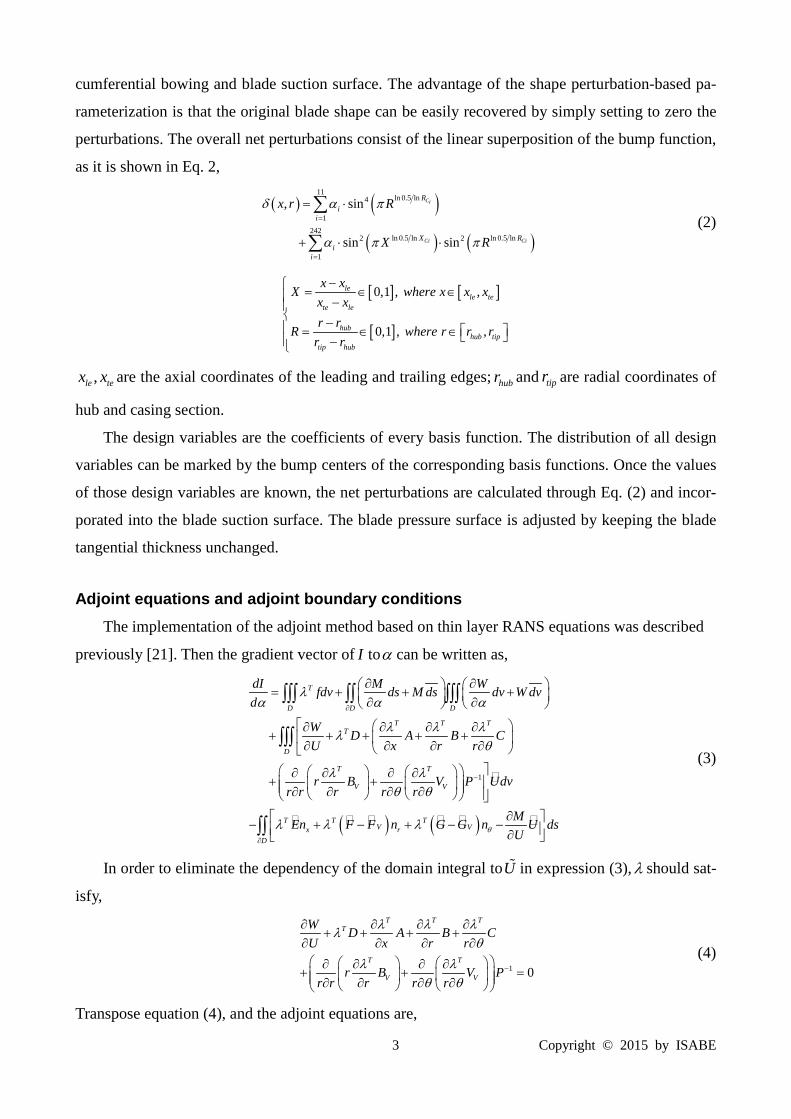
Shape perturbation parameterization Hicks-Henne bump function [25] is used to explore the design space composed of blade cir-
3 Copyright © 2015 by ISABE
cumferential bowing and blade suction surface. The advantage of the shape perturbation-based pa-
rameterization is that the original blade shape can be easily recovered by simply setting to zero the
perturbations. The overall net perturbations consist of the linear superposition of the bump function,
as it is shown in Eq. 2,
( ) ( )
( ) ( )
11ln 0.5 ln4
1242
ln 0.5 ln ln 0.5 ln2 2
1
, sin
sin sin
Ci
Ci Ci
Ri
i
X Ri
i
x r R
X R
δ α π
α π π
=
=
= ⋅
+ ⋅ ⋅
∑
∑ (2)
[ ] [ ]
[ ]
0,1 , ,
0,1 , ,
lele te
te le
hubhub tip
tip hub
x xX where x x x
x xr r
R where r r rr r
− = ∈ ∈ − − = ∈ ∈ −
,le tex x are the axial coordinates of the leading and trailing edges; hubr and tipr are radial coordinates of
hub and casing section.
The design variables are the coefficients of every basis function. The distribution of all design
variables can be marked by the bump centers of the corresponding basis functions. Once the values
of those design variables are known, the net perturbations are calculated through Eq. (2) and incor-
porated into the blade suction surface. The blade pressure surface is adjusted by keeping the blade
tangential thickness unchanged.
Adjoint equations and adjoint boundary conditions The implementation of the adjoint method based on thin layer RANS equations was described
previously [21]. Then the gradient vector of I toα can be written as,
( ) ( )
1
T
D D D
T T TT
D
T T
V V
T T TV Vx r
dI M Wfdv ds M ds dv W dvd
W D A B CU x r r
r B V P Udvr r r r r
MEn F F n G G n UUθ
λα α α
λ λ λλθ
λ λθ θ
λ λ λ
∂
−
∂ ∂ = + + + ∂ ∂
∂ ∂ ∂ ∂+ + + + + ∂ ∂ ∂ ∂
∂ ∂ ∂ ∂+ + ∂ ∂ ∂ ∂
∂ − + − + − − ∂
∫∫∫ ∫∫ ∫∫∫
∫∫∫
D
ds∂
∫∫
(3)
In order to eliminate the dependency of the domain integral toU in expression (3),λ should sat-
isfy,
1 0
T T TT
T T
V V
W D A B CU x r r
r B V Pr r r r r
λ λ λλθ
λ λθ θ
−
∂ ∂ ∂ ∂+ + + +
∂ ∂ ∂ ∂ ∂ ∂ ∂ ∂
+ + = ∂ ∂ ∂ ∂
(4)
Transpose equation (4), and the adjoint equations are,
4 Copyright © 2015 by ISABE
1 0
TT T T T
TT T
V V
WA B C Dx r r U
r B V Pr r r r r
λ λ λ λθ
λ λθ θ
−
∂ ∂ ∂ ∂ + + + + ∂ ∂ ∂ ∂
∂ ∂ ∂ ∂+ + = ∂ ∂ ∂ ∂
(5)
There are also four kinds of boundary in adjoint field similar to flow field. In periodic boundary,
the boundary integral depending onU in expression (3) will be automatically cancelled due to the
symmetry of periodic boundary geometry. For another three kinds of boundary,λ should satisfy,
( ) ( ) 0T T TV Vx r
MEn F F n G G n UUθλ λ λ ∂
+ − + − − =∂
(6)
According to literature [11], the propagation directions of character information in adjoint field
are anti-physical, and the character velocity vector in adjoint field is opposite to that in flow field.
(1) Inlet boundary conditions
At inlet, 1, 0x rn n nθ= − = = , therefore equation (6) can be simplified,
0T ME UU
λ ∂− =∂
(7)
There is only one negative character velocity at the subsonic inlet boundary of adjoint field,
only one equation should be provided. ConsideringU is a function of static pressure p at inlet, we
have
,E p U pE Up pα α
∂ ∂ ∂ ∂= × = ×∂ ∂ ∂ ∂
(8)
Then, the inlet boundary condition is,
0T E Mp p
λ ∂ ∂+ =
∂ ∂ (9)
(2) Outlet boundary conditions
At outlet, 1, 0r xn n nθ= + = = . In a similar way, four equations should be provided at the sub-
sonic outlet boundary due to four negative character velocities, as follows,
0T VFF Mq q q
λ∂ ∂ ∂
+ − = ∂ ∂ ∂ (10)
where , , ,x rq V V Vθρ=
(3) Solid boundary conditions
At outlet, 0nV = , and only one equation should be specified. The solid boundary is slip, and
then the boundary condition should be,
2 3 4 5x rMn n rn wrnpθ θλ λ λ λ ∂
+ + + =∂
(11)
If the solid boundary is adiabatic, we also have,

5 Copyright © 2015 by ISABE
5 0nλ∂
=∂
(12)
Where n indicates the normal direction.
The formulation procedure using continuous adjoint method coupled with the thin shear-layer
N-S equations in a cylindrical-coordinate system [22] is classified into three steps. The first step is
to linearize N-S equations, the second step is to formulate the adjoint partial differential equations,
and the third step is to discretize the adjoint equations for its numerical solving.
Case Description A high pressure ratio centrifugal compressor based on the experimental setup by Krain et al [26]
was chosen. The impeller design data are shown in Table 1. Further details can be taken from [6].
Table 1 Impeller design data SRV2-O
Inlet Total Pressure 0P 101325 Pa
Inlet Total Temperature 0T 288.15 K
Shaft Speed n 50000 rpm
Blade Count Full/Splitter f sz z 13/13 rpm
Mass Flow Rate m 2.55 /kg s
Blade Angle LE Tip 1tβ 26.5 deg
Impeller Tip Radius 2r 112 mm
Blade Angle TE 2β 52 deg
Impeller Press. Ratio 12π 6.1
Efficiency 12η 0.84
To make the Krain adapt our optimization solver, some modifications are applied to the impel-
ler. Firstly, the structure of leading and trailing edge were modified into rounded, as shown in Fig-
ure 1. Secondly, cancel the vaneless diffuser and reduce the exit area as shown in Figure 2. The flow
path inlet axial coordinate is 100mm. The outlet of the impeller radius coordinate is 130mm.
The performances of impeller with rounded leading and trailing edge in original flow path and
modified path are shown in Figure 3. The mass flow rate is normalized by its choked values. The
maximum stage pressure ratio is 6.8 with a corresponding isentropic efficiencyη of about 78% in
original path. The maximum stage pressure ratio is 7.3 with a corresponding isentropic efficien-
cyη of about 88% in modified path. The impeller in modified path has much shorter inlet domain
and without vaneless diffuser, so the isentropic efficiency is much higher than that in original path.

6 Copyright © 2015 by ISABE
The inlet conditions are the same, but the inlet positions are different, so they have different in stage
pressure ratio.
Main Splitter Main Splitter
Figure 1 Modified structure of leading edge (left) and trailing edge (right)
Original Modified
Figure 2 Flow path of Krain
Figure 3 Performance of the original path (left) and modified path (b) impeller.

7 Copyright © 2015 by ISABE
Results and Discussions The modified impeller is selected in this study. The design optimization is carried out at near
peak-efficiency operating point with its performance listed in Table 1. 242 design variables are used
to parameterize the blade shape perturbations, and 11 design variables are used to parameterize the
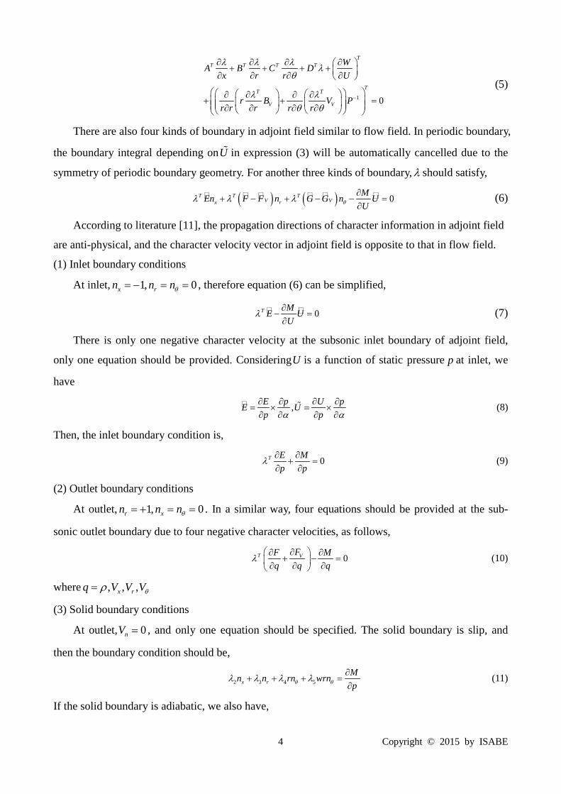
stacking line of the blade. The evolution of the entropy, isentropic efficiency and two constraints
with design cycles is showed in Figure 4. The reduction of entropy means the increasing of the is-
entropic efficiency. The isentropic efficiency is increased by 0.4%, with the total pressure ratio de-
creased by 0.2% and mass flow rate increased by 0.8% respectively.
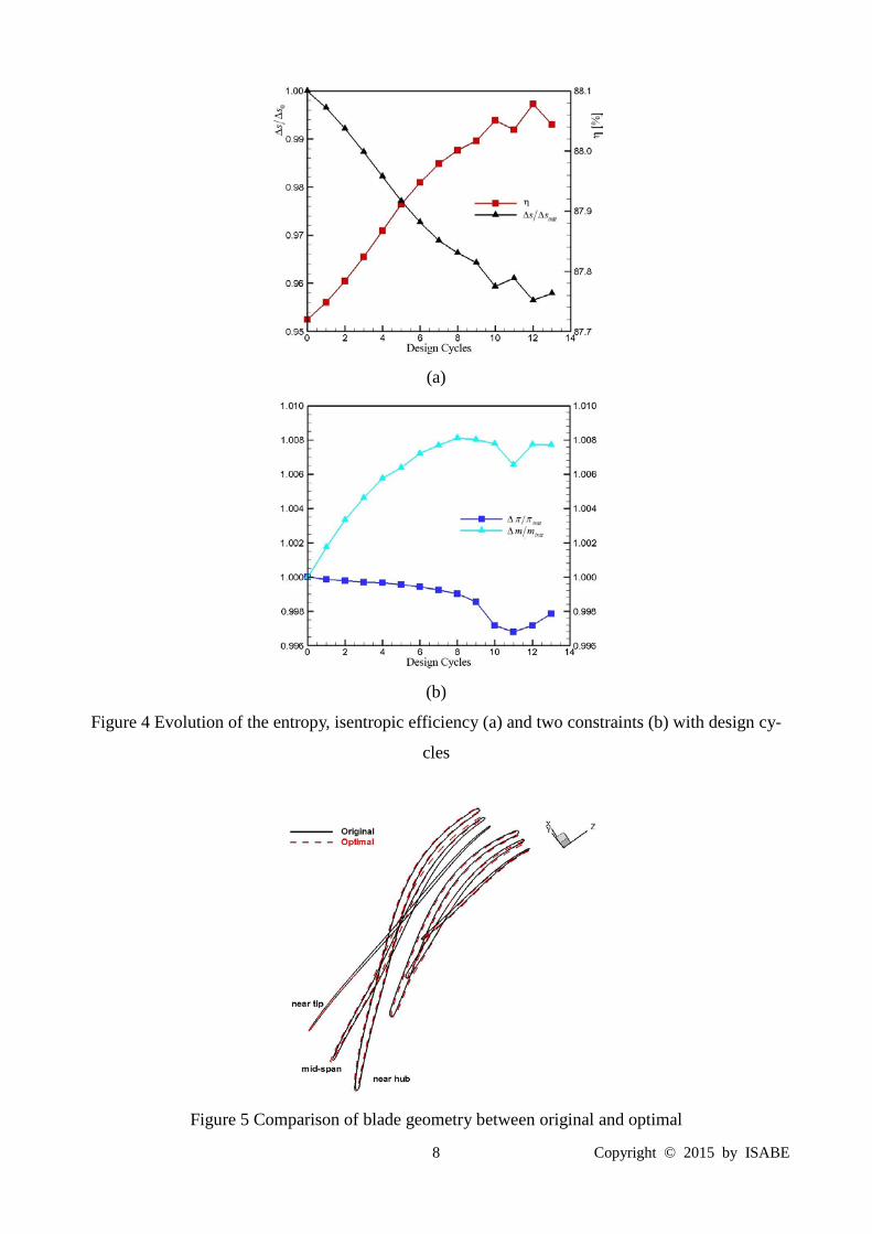
The change of blade geometry is revealed in Figure 5. The profiles of main blade near un-
changed at tip region, but other spanwise move towards to left side of picture, especially at
mid-span. The profiles of splitter move towards to right side of picture at whole spanwise. The
change of blade geometry makes the flow field better. Figure 6 presents the contours of
blade-to-blade relative Mach number at 50% span and 90% span. As Figure 6 shows, the strength of
shock at leading edge region in main blade is reduced. At 90% span, the low speed region between
pressure surface of main blade and suction surface of splitter is decreased. Though the improvement
of flow field is not such significant, it still makes the isentropic efficiency increased by 0.4%.
The comparison is with the impeller global data, i.e. pressure ratio and efficiency vs. mass flow
rate, as shown in Figure 7. The comparison of the pressure ratio shows a very good agreement at
three different rotational speeds over the whole mass flow range. At the same time, the efficiency
has a 0.4% improvement by redesigned at three different rotational speeds. This shows that the re-
designed impeller has 0.4% improvement in modified flow path.
Considering the original flow path is much different to the modified one. The redesigned blade
was calculated in original flow path, the results are shown in Figure 8. From the comparison at
50,000 rpm, the efficiency has a nearly 0.4% improvement and the pressure ratio keeps unchanged.
This is consistent with the calculation in modified flow path. In other word, the optimization of the
impeller is effective, and the result is reliable.
Table 1 Performance comparison between the original and optimized blades
η initπ π initm m Original 0.877 1.000 1.000
Optimal 0.881 0.998 1.008
8 Copyright © 2015 by ISABE
(a)
(b)
Figure 4 Evolution of the entropy, isentropic efficiency (a) and two constraints (b) with design cy-
cles
Figure 5 Comparison of blade geometry between original and optimal

9 Copyright © 2015 by ISABE
Original Optimal
(a)
Original Optimal
(b)
Figure 6 Contours of relative Mach number on blade to blade: (a) at 50% span, (b) at 90% span

10 Copyright © 2015 by ISABE
Figure 7 Efficiency and pressure ratio over mass flow rate for three rotational speeds
Figure 8 Efficiency and pressure ratio over mass flow rate in original flow path (50000rpm)
Conclusions In this paper, a constrained gradient evaluation is used for centrifugal impeller, and a continu-
ous adjoint method for the thin shear-layer N-S equations in a cylindrical-coordinate system is de-
veloped. With the adjoint-based gradient evaluation, perturbation-based shape representation, and
the steepest descent method, an efficient integrated shape optimization loop is constructed.
The proposed method is used to optimize the shape of the Krain impeller. The optimization is
able to raise the isentropic efficiency of the blade by 0.4% while maintaining the same mass flow
rate and total pressure ratio. Though the improvement of the isentropic efficiency is not such signif-
icant, it provides a new way to improve the centrifugal impeller.
Acknowledgments The authors would like to express their deep appreciations to the National Natural Science

11 Copyright © 2015 by ISABE
Foundation of China for funding this work, Project No. 51176012.
Nomenclature Symbols
, ,E F G Axial, circumferential, and radial flux vectors
I Objective
N Residual of flow equations
nQ Normal flow flux vector
S∆ Net mass-averaged entropy production rate from the domain inlet to the domain outlet
,U U ′ Conservative and primitive flow variables
, ,u v w Axial, circumferential, and radial velocities
m Inlet and outlet average mass flow rate
, ,x r θ Cylindrical coordinates
, ,x rn n nθ Components of normal direction
α Design variable
1 2 3, ,σ σ σ Weighting factors
π Total pressure Ratio
λ Adjoint variable vector
γ Specific heat ratio
Superscripts and subscripts
( )*
Stagnation parameter ( ) Partial derivatives of flow terms to
design variables
( )init Baseline value ( ) ( ),
hub tip
Blade hub and tip
( ) Average value ( ) ( ),le te Leading and trailing edge
References [1] Krain H., Hoffman W., “Verification of an Impeller by Laser Measurement and 3D Viscous Flow Calculations”,
ASME Paper 89-GT-150, 1989.

12 Copyright © 2015 by ISABE
[2] Rodi W., Majumdar S., Schonung B., “Finite Volume Methods for Two-Dimensional Incompressible Flows with
Complex Boundaries”, Computer Methods in Applied Mechanics and Engineering, vol. 75, pp. 369-392, 1989.
[3] Lakshminarayana B., “An Assessment of Computational Fluid Dynamic Techniques in the Analysis and Design of
Turbomachinery”, ASME Journal of Fluids Engineering, vol. 113, pp. 315-352, 1991.
[4] Hah C., Krain H., “Secondary Flows and Vortex Motion in High Efficiency Backswept Impeller at the Design and
Off-Design Conditions”. ASME Paper GT93-37, 1993.
[5] Thakur S., Wright J., Shyy W., Liu J., Ouyang H., Vu T., “Development of Pressure-based Composite Multigrid Methods for Complex Fluid Flows”, Program in Aerospace Science, vol. 32, pp. 313-375, 1996.
[6] Eisenlohr G., Krain H., Richter F.A., Tiede V., “Investigations of the Flow through a High Pressure Ratio Cen-
trifugal Impeller”, ASME Paper GT2002-30394, 2002. [7] Reuther J., Jameson A., “Control Based Airfoil Design using the Euler Equations”, AIAA Paper 94-4272, 1994. [8] Reuther J., Jameson A., “Aerodynamic Shape Optimization of Wing and Wing-body Configurations using Control
Theory”, AIAA Paper 95-0123-CP, 1995. [9] Reuther J., Jameson A., Alonso J.J., “Constrained Multipoint Aerodynamic Shape Optimization using an Adjoint
Formulation and Parallel Computers”, AIAA Paper 97-0103, 1997. [10] Jameson A., Pierce N.A., Martinelli L., “Optimum Aerodynamic Design using the Navier-Stokes Equations”, AI-
AA Paper 97-0101, 1997. [11] Giles M.B., Pierce N.A., “An Introduction to the Adjoint Approach to Design”, Flow Turbulence and Combustion
65:393-415, 2000. [12] Jameson A., “Aerodynamic Shape Optimization Using the Adjoint Method, Lectures at the Von Karman Institute”,
Brussels, 2003. [13] Giles M.B., Duta M.C., Muller, J.D., Pierce, N.A., “Algorithm Developments for Discrete Adjoint Methods”, AI-
AA Journal, Vol. 41, No. 2, 2003. [14] Yang S., and Liu F., “Aerodynamic Design of Cascades by Using an Adjoint Equation Method”, AIAA Paper
2003-1068, 2003. [15] Papadimitriou D.I., Giannakoglou, K.C., “Compressor Blade Optimization Using a Continuous Adjoint Formula-
tion”, ASME Paper GT2006-90466, 2006. [16] Duta M.C., Shahpar S., Giles M.B., “Turbomachinery Design Optimization Using Automatic Differentiated Ad-
joint Code”, ASME Paper GT 2007-28329, 2007. [17] Wang D.X., He L., “Adjoint Aerodynamic Design Optimization for Blades in Multi-stage Turbomachines: Part I-
Methodology and Verification”, Journal of Turbomachinery, 132(2), 2010 [18] Wang D.X., He L., “Adjoint Aerodynamic Design Optimization for Blades in Multi-stage Turbomachines: Part II-
Validation and Application”, Journal of Turbomachinery, 132(2), 2010 [19] Li Y.C., Feng Z.P., “Three-Dimensional Aerodynamic Design for Turbine Blades Using the Adjoint Method”,
ASME GT2008-51225, 2008. [20] Walther B., Nadarajah S., “Constrained Adjoint-Based Aerodynamic Shape Optimization of a Single-Stage Tran-
sonic Compressor”, ASME Paper, GT2012-69128, 2012. [21] Li W.W., Tian Y., Yi W.L., Shao W.W., Xiao Y.H, “Study on Adjoint-based Optimization Method for Multi-Stage
Turbomachinery”, Journal of Thermal Science, Vol. 20, No. 5, 2011. [22] Ji L.C., Li W.W., Tian Y., Yi W.L., Chen J., “Multi-Stage Turbomachinery Blades Optimization Design using Ad-
joint Method and Thin Shear-Layer N-S Equations”, ASME Paper GT2012-68537,2012. [23] Oyama A., Liou M.S., “Transonic Axial-Flow Blade Optimization: Evolutionary Algorithms/Three-Dimensional
Navier-Stokes Solver”, Journal of Propulsion and Power, 20(4):612–619, 2004. [24] Wu H., Liu F., and Tsai H., “Aerodynamic Design of Turbine Blades Using an Adjoint Equation Method”, AIAA
Paper, 05-1006, 2005 [25] Hicks R., Henne P., “Wing Design by Numerical Optimization”, Journal of Aircraft, Vol. 15, No. 7, pp. 407-413,
1978. [26] Krain H., Hoffmann B., “Flow Physics in High Pressure Ratio Centrifugal Compressors”, ASME FEDSM98-4853,
1998.