Embed Size (px)
Citation preview
ANGLE
TRANSMITTER
INSTRUCTIONS AND OPERATING
MANUAL
TRAG-7.3
SHW Instrumentação Industrial e Comercial Ltda
R. Paraná, 699-Ourinhos,SP 19.900-021-Fone: 55 14 3326-3161-Fax: 55 14 3326-3162 E-Mail : [email protected]
Page 1
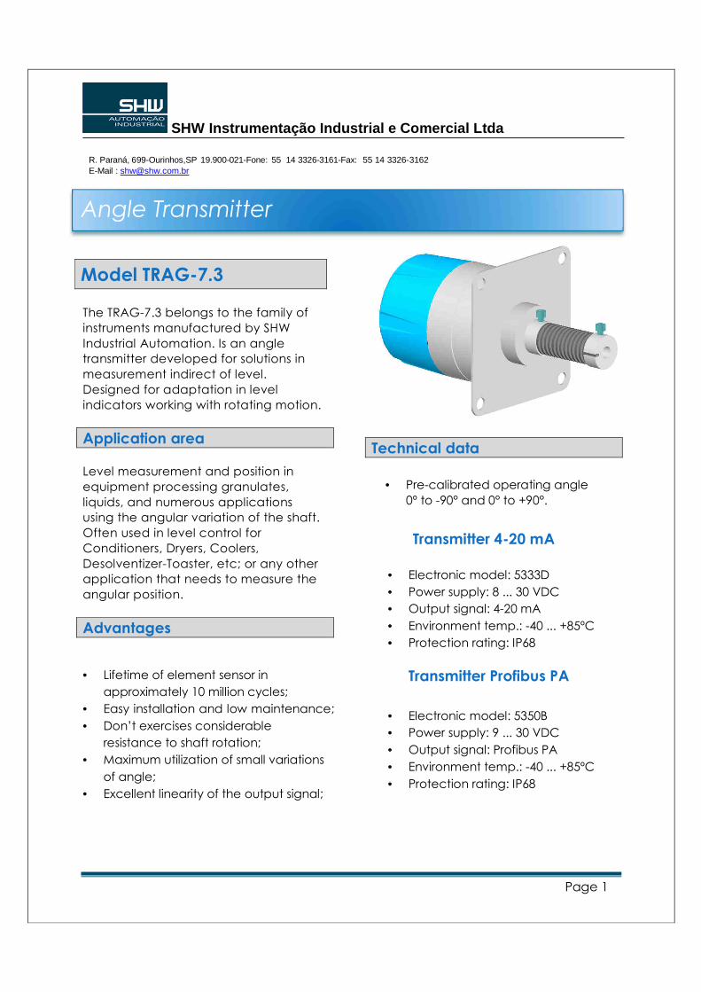
Model TRAG-7.3
The TRAG-7.3 belongs to the family of
instruments manufactured by SHW
Industrial Automation. Is an angle
transmitter developed for solutions in
measurement indirect of level.
Designed for adaptation in level
indicators working with rotating motion.
Application area
Level measurement and position in
equipment processing granulates,
liquids, and numerous applications
using the angular variation of the shaft.
Often used in level control for
Conditioners, Dryers, Coolers,
Desolventizer-Toaster, etc; or any other
application that needs to measure the
angular position.
Advantages
• Lifetime of element sensor in
approximately 10 million cycles;
• Easy installation and low maintenance;
• Don’t exercises considerable
resistance to shaft rotation;
• Maximum utilization of small variations
of angle;
• Excellent linearity of the output signal;
Technical data
• Pre-calibrated operating angle
0º to -90° and 0° to +90°.
Transmitter 4-20 mA
• Electronic model: 5333D
• Power supply: 8 ... 30 VDC
• Output signal: 4-20 mA
• Environment temp.: -40 ... +85ºC
• Protection rating: IP68
Transmitter Profibus PA
• Electronic model: 5350B
• Power supply: 9 ... 30 VDC
• Output signal: Profibus PA
• Environment temp.: -40 ... +85ºC
• Protection rating: IP68
Angle Transmitter
SHW Instrumentação Industrial e Comercial Ltda
R. Paraná, 699-Ourinhos,SP 19.900-021-Fone: 55 14 3326-3161-Fax: 55 14 3326-3162 E-Mail : [email protected]
Page 2
The process connection
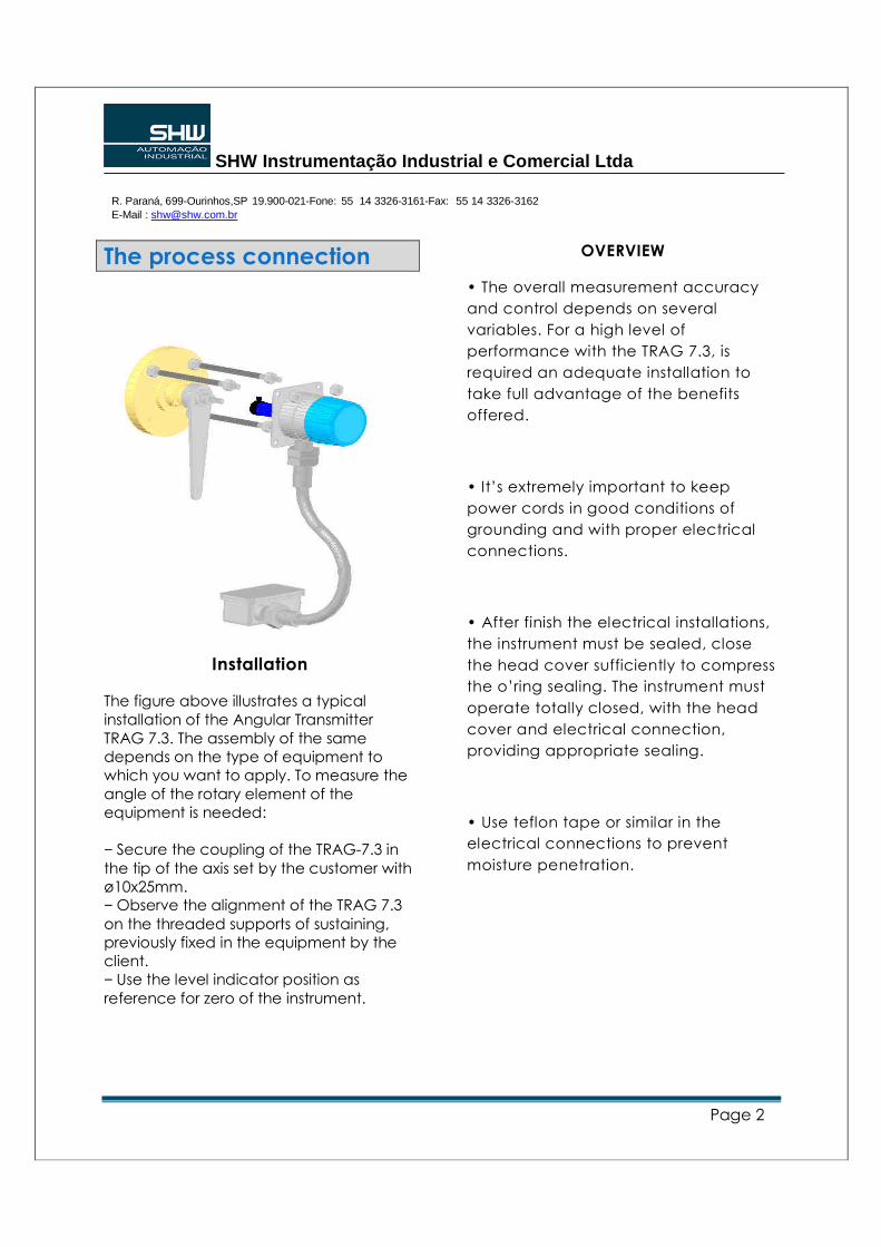
Installation
The figure above illustrates a typical installation of the Angular Transmitter TRAG 7.3. The assembly of the same depends on the type of equipment to which you want to apply. To measure the angle of the rotary element of the equipment is needed: − Secure the coupling of the TRAG-7.3 in
the tip of the axis set by the customer with ø10x25mm. − Observe the alignment of the TRAG 7.3
on the threaded supports of sustaining, previously fixed in the equipment by the client. − Use the level indicator position as
reference for zero of the instrument.
OVERVIEW
• The overall measurement accuracy
and control depends on several
variables. For a high level of
performance with the TRAG 7.3, is
required an adequate installation to
take full advantage of the benefits
offered.
• It’s extremely important to keep
power cords in good conditions of
grounding and with proper electrical
connections.
• After finish the electrical installations,
the instrument must be sealed, close
the head cover sufficiently to compress
the o’ring sealing. The instrument must
operate totally closed, with the head
cover and electrical connection,
providing appropriate sealing.
• Use teflon tape or similar in the
electrical connections to prevent
moisture penetration.
SHW Instrumentação Industrial e Comercial Ltda
R. Paraná, 699-Ourinhos,SP 19.900-021-Fone: 55 14 3326-3161-Fax: 55 14 3326-3162 E-Mail : [email protected]
Page 3
Electrical connection
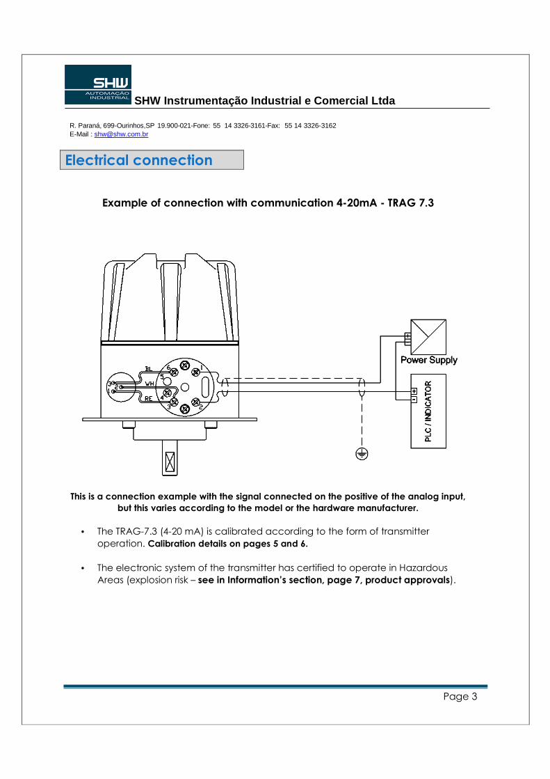
Example of connection with communication 4-20mA - TRAG 7.3
This is a connection example with the signal connected on the positive of the analog input,
but this varies according to the model or the hardware manufacturer.
• The TRAG-7.3 (4-20 mA) is calibrated according to the form of transmitter
operation. Calibration details on pages 5 and 6.
• The electronic system of the transmitter has certified to operate in Hazardous
Areas (explosion risk – see in Information’s section, page 7, product approvals).
SHW Instrumentação Industrial e Comercial Ltda
R. Paraná, 699-Ourinhos,SP 19.900-021-Fone: 55 14 3326-3161-Fax: 55 14 3326-3162 E-Mail : [email protected]
Page 4
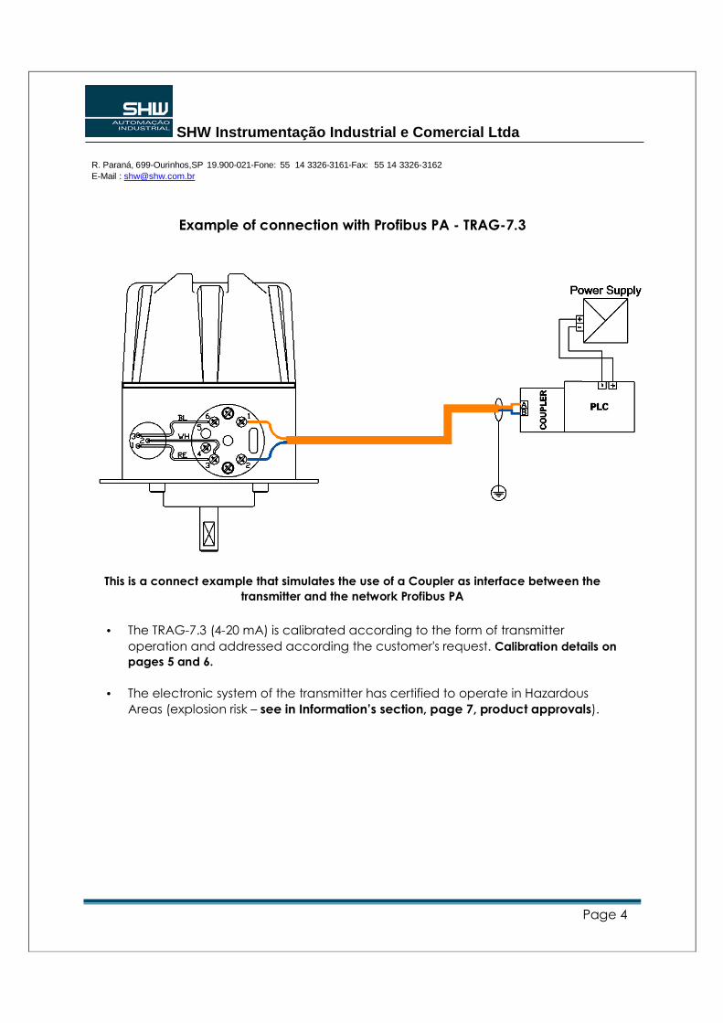
Example of connection with Profibus PA - TRAG-7.3
This is a connect example that simulates the use of a Coupler as interface between the
transmitter and the network Profibus PA
• The TRAG-7.3 (4-20 mA) is calibrated according to the form of transmitter
operation and addressed according the customer's request. Calibration details on
pages 5 and 6.
• The electronic system of the transmitter has certified to operate in Hazardous
Areas (explosion risk – see in Information’s section, page 7, product approvals).
SHW Instrumentação Industrial e Comercial Ltda
R. Paraná, 699-Ourinhos,SP 19.900-021-Fone: 55 14 3326-3161-Fax: 55 14 3326-3162 E-Mail : [email protected]
Page 5
Technical notes
• Avoid passing the signal cables by routes they have power cables or electrical switches.
• If the cable is shielded, it’s recommended to ground the shield at only one end, and the end
not used should be carefully isolated.
• The access of the cables to the connection terminals is made by a passage in the housing
where is possible insert a conduit pipe or cable gland. The conduit pipe threads should be
sealed in according with the required sealing method by the area.
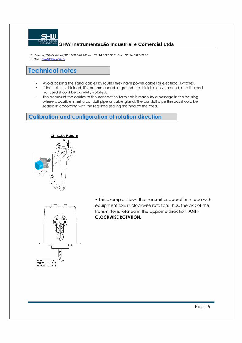
Calibration and configuration of rotation direction
• This example shows the transmitter operation mode with
equipment axis in clockwise rotation. Thus, the axis of the
transmitter is rotated in the opposite direction, ANTI-
CLOCKWISE ROTATION.
SHW Instrumentação Industrial e Comercial Ltda
R. Paraná, 699-Ourinhos,SP 19.900-021-Fone: 55 14 3326-3161-Fax: 55 14 3326-3162 E-Mail : [email protected]
Página 6
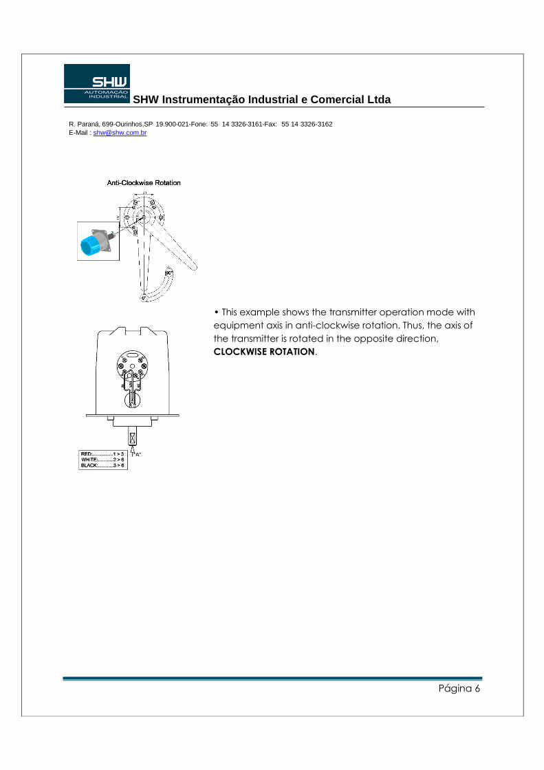
• This example shows the transmitter operation mode with
equipment axis in anti-clockwise rotation. Thus, the axis of
the transmitter is rotated in the opposite direction,
CLOCKWISE ROTATION.
SHW Instrumentação Industrial e Comercial Ltda
R. Paraná, 699-Ourinhos,SP 19.900-021-Fone: 55 14 3326-3161-Fax: 55 14 3326-3162 E-Mail : [email protected]
Página 7
Technical Information
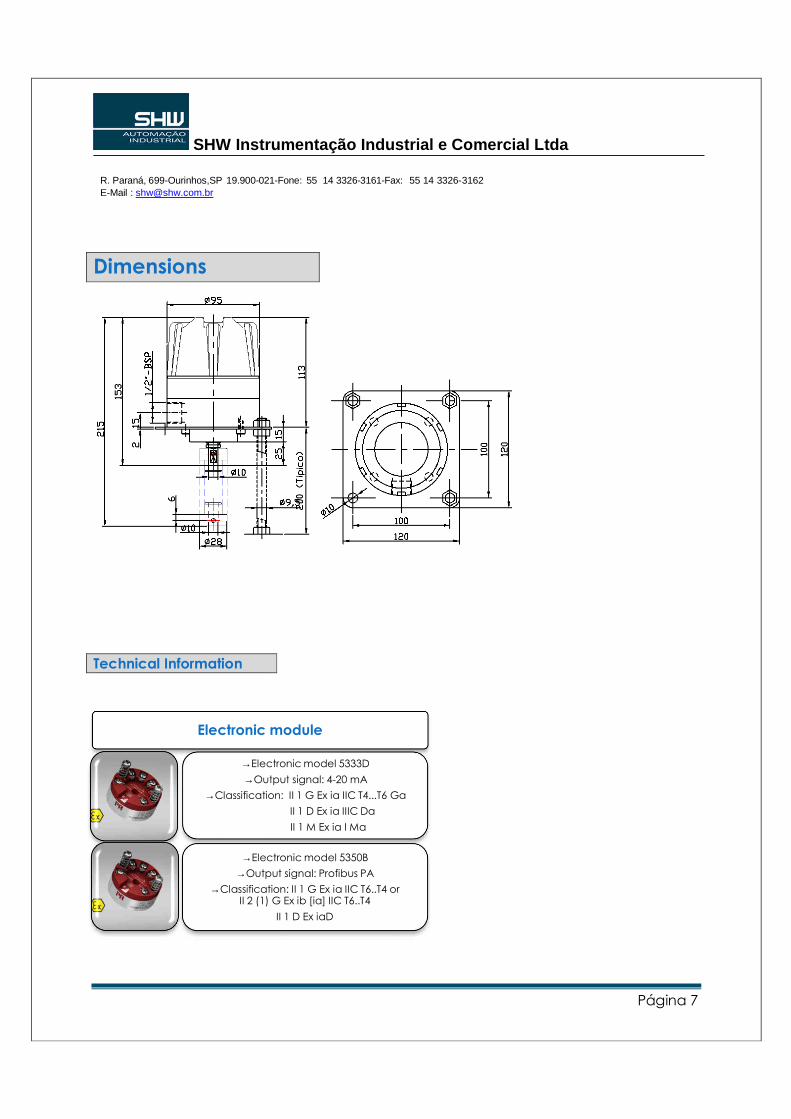
Dimensions
Electronic module
→Electronic model 5333D
→Output signal: 4-20 mA
→Classification: II 1 G Ex ia IIC T4...T6 Ga
II 1 D Ex ia IIIC Da
II 1 M Ex ia I Ma
→Electronic model 5350B
→Output signal: Profibus PA
→Classification: II 1 G Ex ia IIC T6..T4 or II 2 (1) G Ex ib [ia] IIC T6..T4
II 1 D Ex iaD