Embed Size (px)
Citation preview
7/21/2019 Martinez ENG
http://slidepdf.com/reader/full/martinez-eng 1/10
Estimating internal corrosion rate... S. Martinez
134 goriva i maziva, 52, 2 : 134-143, 2013.
Sanja Martinez
ISSN 0350-350X
GOMABN 52, 2, 134-143
Stručni rad / Professional paper
ESTIMATING INTERNAL CORROSION RATEAND INTERNAL INSPECTION INTERVAL OF
ABOVEGROUND HYDROCARBONSTORAGE TANKS
Abstract
Corrosion of aboveground storage tanks (AST) in hydrocarbon service shortens thetank’s life cycle and can lead to leaks and release of hazardous materials into theenvironment. Internal inspection is one of the main means to keep the tank’sintegrity. Determination of internal inspection interval is imminent for balancing thesafe operation requirement and inspection costs. In most instances, the area mostvulnerable to corrosion in upright atmospheric AST is the tank bottom. In this paper
we present the procedure for calculation of reasonable internal inspection intervalbased on deterministic method. Calculation and/or anticipation of the key parameter,the bottom plate corrosion rate is discussed. Corrosion rates between 0.1 and 0.9mm year
-1 of the thank bottoms that are typically 6.4 mm to 9.5 mm thick show that
corrosion is an important concern in the case of long-term storage industrial tanks. Itis demonstrated that precise determination of the bottom plate corrosion rate iscrucial for the obtaining reliable internal inspection interval.
Keywords: corrosion, aboveground storage tank, crude oil storage
PROCJENA BRZINE UNUTARNJE KOROZIJEI INTERVALA INSPEKCIJE NADZEMNIH
SPREMNIKA ZA NAFTU I NAFTNE DERIVATE
Korozija nadzemnih spremnika s naftom i naftnim derivatima skraćuje životni ciklusspremnika i može dovesti do njihova curenja i ispuštanja opasnih tvari u okoliš.Unutarnja inspekcija jedno je od glavnih sredstava za očuvanje integritetaspremnika. Pravilno određivanje intervala unutarnje inspekcije neophodno je zauravnoteženje zahtjeva sigurnog rada i troškova inspekcije. Najugroženije područjes obzirom na koroziju u uspravnim nadzemnim atmosferskim spremnicima je u
najvećem broju slučajeva dno spremnika.
7/21/2019 Martinez ENG
http://slidepdf.com/reader/full/martinez-eng 2/10
S. Martinez Estimating internal corrosion rate…
goriva i maziva, 52, 2 : 134-143, 2013. 135
U ovom radu smo prikazali postupak za izračun intervala unutarnje inspekcije koji se
temelji na determinističkom pristupu. Objašnjen je izračun i / ili procjena brzinekorozije dna spremnika koja je ključni parametar za izračun intervala inspekcije.Brzine korozije između 0,1 i 0,9 mm god
-1 na dnu koje je obično debljine 6,4 do 9,5
mm pokazuju da je korozija važan problem u slučaju industrijskih spremnika zadugotrajnu pohranu nafte i naftnih derivata. Pokazano je da je precizno određivanjebrzine korozije dna spremnika ključno za dobivanje pouzdanih intervala interneinspekcije.
Ključne riječi: korozija, nadzemni spremnik, skladištenje nafte
Introduction
With the rapid development of petroleum and chemical industry, storage tank playsan increasing role in the storage of crude oil and its derivatives. The tank interior,and particularly the tank bottom, is prone to corrosion [1, 2]. The thickness of thetank bottom is reduced by both, topside and underside or “soil side“ corrosion [3]. Bythe internal inspection, the real corrosion rate of tank bottom can be determined, andfollowing repair works can ensure tank’s longtime safe operation in the future. Thisapproach may results in two short-comings for tanks management, under-inspectionor over-inspection. On the one hand, there is the risk of environmental damagecaused by leaking tanks and the high cost of environmental cleanup, and on theother hand, there is the cost of cleaning tanks and the temporary loss of storage
volume or plant operating issues that can be extremely costly. Hence, tanks ownershave a keen interest in lengthening the service interval of their tanks to the extentthat the minimum thickness of the bottom is attained prior to the next scheduledinspection. The in-service code for atmospheric storage tanks is API STD 653 [4].The content in API STD 653 covers tank inspection, repair, alteration andreconstruction. Until 1991 when API issued the first edition of Standard 653,estimating the service interval of storage tank bottoms had been based on suchfactors as visual observations, operating history, and general experience with similartanks. API STD 653 includes a section on how to determine the service interval ofan AST bottom. The API approach is to gather data through an internal inspectionand calculate corrosion rates, provide limits on minimum bottom thickness, and
establish the schedule for the next internal inspection.
Quantifying the inspection interval can be done by probabilistic or deterministicmethods [4, 5]. Probabilistic method uses a statistical approach to extrapolate arelatively small amount of inspection data into a prediction of inspection interval. Thedeterministic method uses more extensive inspection data to quantify the remainingthickness of the bottom. The key calculation parameters are maximum internal andunderside corrosion rates. Current trends appear to be directed toward increaseduse of the deterministic approach. In-field integrity evaluation of the bottom platerequires a good understanding of inspection techniques, their limitations, andacceptance criteria. In this paper we present the procedure for calculation of
reasonable internal inspection interval based on deterministic method.
7/21/2019 Martinez ENG
http://slidepdf.com/reader/full/martinez-eng 3/10
Estimating internal corrosion rate... S. Martinez
136 goriva i maziva, 52, 2 : 134-143, 2013.
Corrosion causes of AST bottoms
Crude oil represents a mixture of a large variety (thousands) of organic substances,mainly HCs, with some admixture of oxygen-, nitrogen-, sulphur-containing organiccompounds and some inorganic species (metals etc). HCs can be straight andbranched, saturated and unsaturated aliphatic, alicyclic, aromatic and polyaromaticcompounds [6]. The refinery products are also mixtures containing straight-chainand branched chain hydrocarbons, alkenes, naphtalenes, aromatics, and othercompounds [7]. Oil and its derivatives should not be corrosive to metals. Theaccumulation of water at the bottom of storage tanks is a primary prerequisite fordevelopment of corrosion. Generally, it is extremely difficult to avoid the occurrenceof water in tanks. The basic sediment and water (BS&W) content of crude oil in
storage and transport facilities is usually limited to 0.5 volume percent [8]. However,water and water vapours may ingress into crude oil and its derivatives duringstorage, transportation, and some other operations [9]. Because of the high polarityof water molecules the water drops separate from the organic phase on the steelsurfaces forming a water pillow at the bottom of the tanks and electrochemicalcorrosion of steel takes place.
Processes of bottom corrosion may proceed even more intensively due to upperinflow of oxygen into the tanks [6]. The solubility of oxygen in hydrocarbons is higher(60 to 70 ppm) than in water (8 ppm). Therefore, oxygen diffuses from the organicphase (hydrocarbons or fuel) to the water phase according to the solubility in each
phase, and the concentration gradient increases up to oxygen saturation in theaqueous phase [10]. Concentration cell corrosion may occur when a surfacedeposit, mill scale, or crevice creates a localized area of lower oxygen concentration[11]. The difference in oxygen concentration between the inaccessible area and thebulk electrolyte creates a concentration cell and may result in significant localizedmetal loss. The extent of internal corrosion is also influenced by the temperature,CO2, H2S and salts (sodium chloride, calcium chloride, and magnesium chloride),light organic acids, etc. Some of the aggressive species are typically separated fromcrude during production operations performed at low pressure (atmospheric up to 1bar gauge pressure) or in various technological processes such as desalting andrectification of crude. In the tank, remaining aggressive variables undergo extractionfrom organic phase into the aqueous phase and may cause a decrease in the pHand increase in the water corrosivity. Even in the absence of abiotic corrosivefactors, the bacteria are known to cause severe internal corrosion problems in crudeoil storage and transport [6]. Ability of microorganisms to grow both in a water phaseand on inter-phase of water/hydrocarbon as well as the generation of products oftheir metabolism worsen the physical and chemical properties of oils and fuels.
Activity of microorganisms promotes an increase of suspended solids content andformation of corrosive sludge at the bottom of tanks. Microbial degradation of HCsand other organic compounds increases the water content in sludge, which canexceed 10%. Pitting corrosion has been observed underneath sludge deposits that
are a mix of sand and clay particles, water, and oil products [8].
7/21/2019 Martinez ENG
http://slidepdf.com/reader/full/martinez-eng 4/10
S. Martinez Estimating internal corrosion rate…
goriva i maziva, 52, 2 : 134-143, 2013. 137
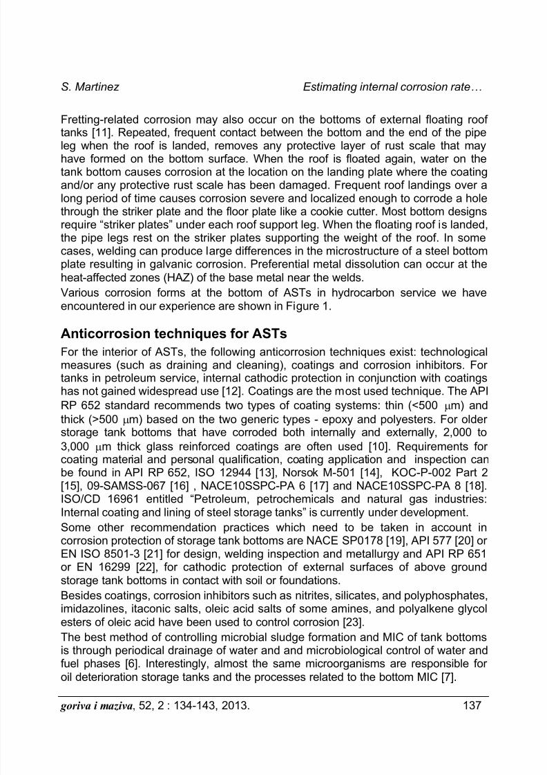
Fretting-related corrosion may also occur on the bottoms of external floating roof
tanks [11]. Repeated, frequent contact between the bottom and the end of the pipeleg when the roof is landed, removes any protective layer of rust scale that mayhave formed on the bottom surface. When the roof is floated again, water on thetank bottom causes corrosion at the location on the landing plate where the coatingand/or any protective rust scale has been damaged. Frequent roof landings over along period of time causes corrosion severe and localized enough to corrode a holethrough the striker plate and the floor plate like a cookie cutter. Most bottom designsrequire “striker plates” under each roof support leg. When the floating roof is landed,the pipe legs rest on the striker plates supporting the weight of the roof. In somecases, welding can produce large differences in the microstructure of a steel bottomplate resulting in galvanic corrosion. Preferential metal dissolution can occur at theheat-affected zones (HAZ) of the base metal near the welds.
Various corrosion forms at the bottom of ASTs in hydrocarbon service we haveencountered in our experience are shown in Figure 1.
Anticorrosion techniques for ASTs
For the interior of ASTs, the following anticorrosion techniques exist: technologicalmeasures (such as draining and cleaning), coatings and corrosion inhibitors. Fortanks in petroleum service, internal cathodic protection in conjunction with coatingshas not gained widespread use [12]. Coatings are the most used technique. The API
RP 652 standard recommends two types of coating systems: thin (<500 m) andthick (>500 m) based on the two generic types - epoxy and polyesters. For olderstorage tank bottoms that have corroded both internally and externally, 2,000 to
3,000 m thick glass reinforced coatings are often used [10]. Requirements forcoating material and personal qualification, coating application and inspection canbe found in API RP 652, ISO 12944 [13], Norsok M-501 [14], KOC-P-002 Part 2[15], 09-SAMSS-067 [16] , NACE10SSPC-PA 6 [17] and NACE10SSPC-PA 8 [18].ISO/CD 16961 entitled “Petroleum, petrochemicals and natural gas industries:Internal coating and lining of steel storage tanks” is currently under development.
Some other recommendation practices which need to be taken in account in
corrosion protection of storage tank bottoms are NACE SP0178 [19], API 577 [20] orEN ISO 8501-3 [21] for design, welding inspection and metallurgy and API RP 651or EN 16299 [22], for cathodic protection of external surfaces of above groundstorage tank bottoms in contact with soil or foundations.
Besides coatings, corrosion inhibitors such as nitrites, silicates, and polyphosphates,imidazolines, itaconic salts, oleic acid salts of some amines, and polyalkene glycolesters of oleic acid have been used to control corrosion [23].
The best method of controlling microbial sludge formation and MIC of tank bottomsis through periodical drainage of water and and microbiological control of water andfuel phases [6]. Interestingly, almost the same microorganisms are responsible for
oil deterioration storage tanks and the processes related to the bottom MIC [7].
7/21/2019 Martinez ENG
http://slidepdf.com/reader/full/martinez-eng 5/10
Estimating internal corrosion rate... S. Martinez
138 goriva i maziva, 52, 2 : 134-143, 2013.
To inhibit or prevent bacterial deterioration of fuels and MIC, bactericides are
sometimes injected. The souring caused by sulphate reducing bacteria can bereversed by nitrate additions that act trough biocompetitive exclusion i.e. growth ofcompeting bacterial populations (nitrate reducing bacteria) [24]. If microbial sludgehas already formed at the bottom, there is a great chance that bactericides wouldnot prevent the development of MIC.
a) b)
c) d)
Figure 1: Various forms of corrosion in the interior of a crude oil tank:a) fretting corrosion below the floating roof legs,b) pitting corrosion at coating defect,c) pitting corrosion at poorly coated irregular weld,d) heat affected zone weld corrosion after abrasive cleaning.
7/21/2019 Martinez ENG
http://slidepdf.com/reader/full/martinez-eng 6/10
S. Martinez Estimating internal corrosion rate…
goriva i maziva, 52, 2 : 134-143, 2013. 139
Calculation of corrosion rate from MFL and laboratory
measurementsMagnetic flux leakage (MFL) tools are commonly used, along with ultrasonic (UT)thickness measurement tools, to examine the entire tank bottoms [4, 25]. Thetechnique requires that the MFL equipment be set to several fixed thickness lossthresholds (typically 30 %, 60 % and 80 % of the original plate thickness) and theMFL equipment will identify any locations with loss greater than those thresholdsettings, but it will not quantify the thickness. Under normal conditions, pitting asshallow as 1.8 mm can be detected by MFL in 9.5-millimeter bottom plate (19 %threshold). Scanning rates vary and depend on the general condition of the tankbottom and the number of indications that are found. Newer MFL equipment can
distinguish or differentiate corrosion originating at the soil side from corrosionoriginating at the product side, while older MFL equipment cannot. Ultrasonicthickness measurement techniques are often used to confirm and further quantifydata obtained by MFL examination.
A linear decrease in bottom plate thickness, i.e. a constant corrosion rate, Cr , is
assumed and calculated by the equation:
0
Th Tr Cr
In In
(1)
Tr is the minimum threshold above which defects have not been observed hence Tr
gives the minimum possible thickness of the plate. Th is the original thickness of thebottom plate and In is the time interval from the previous internal inspection.Corrosion rate may be underestimated if credit is not given to the protective capacityof tank bottom lining system. The corrosion rate of a tank bottom with an internallining and bottom side cathodic protection can be assumed to be zero for a periodtime until coating failures start to appear. E.g. based on the durability of the appliedlining In0 equal to 5 years may be assumed.
Bottom corrosion rate of gasoline tanks equal to 0.04-0.13 mm year -1
and ofkerosene tanks equal to 0.04-0.1 mm year
-1 may be found in literature [10, 26]. The
average literature value for corrosion rate of: crude oil tanks is 0.3 mm year -1
, gas oil
tanks is 0.5 mm year -1, diesel oil tanks is is 0.5 mm year -1 and fuel oil tanks is 0.28mm year
-1. For crude oil tanks the corrosion rate was also found to vary between 0.1
and 0.9 mm year -1
[5], e.g. for a set of 20 crude oil ASTs in similar service the
corrosion rate was found to be 0.380.19 mm year -1. API 652 states that pitting
corrosion of a bare steel tank bottom may occur at a rate as high as 2.0 mm peryear. Our laboratory measurements have yielded the value of carbon steel corrosion
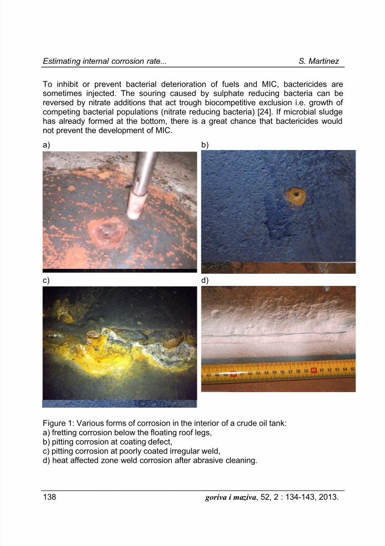
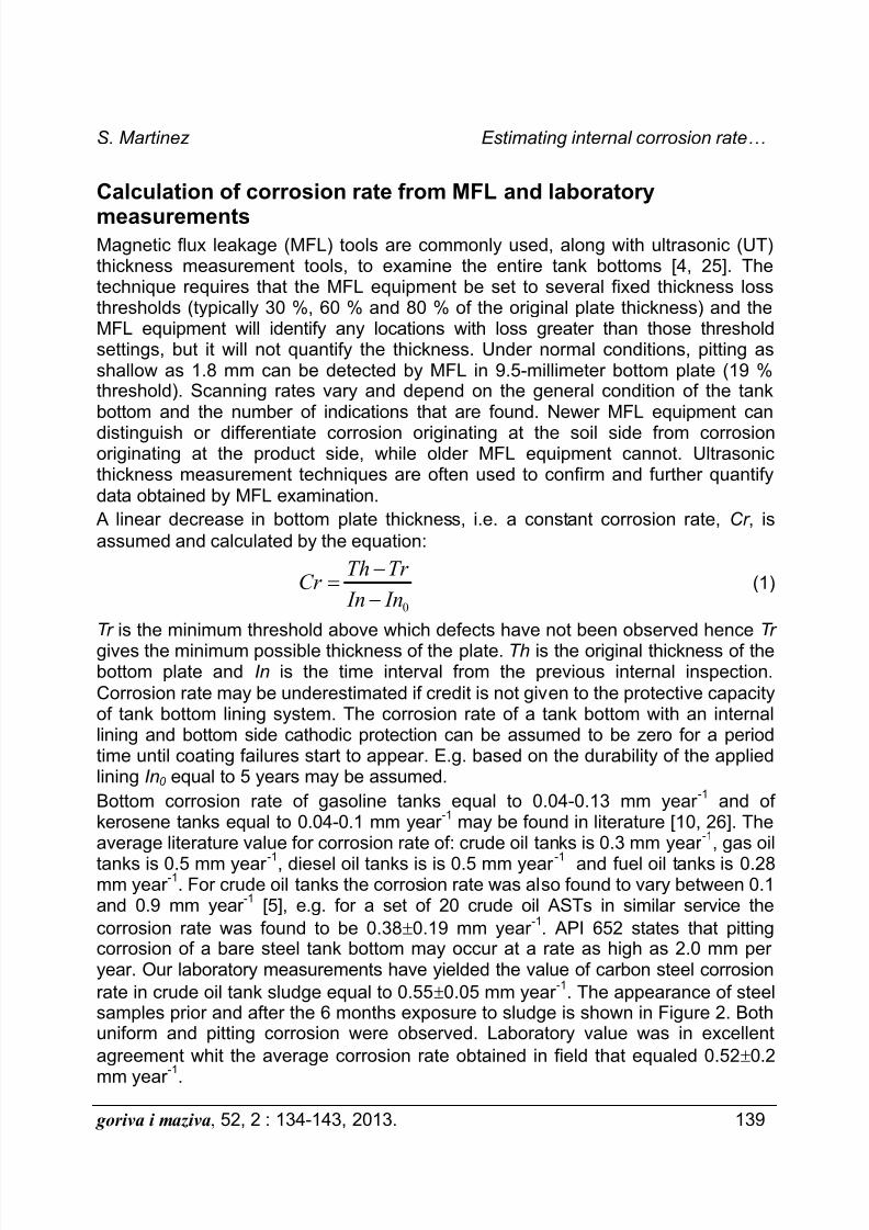
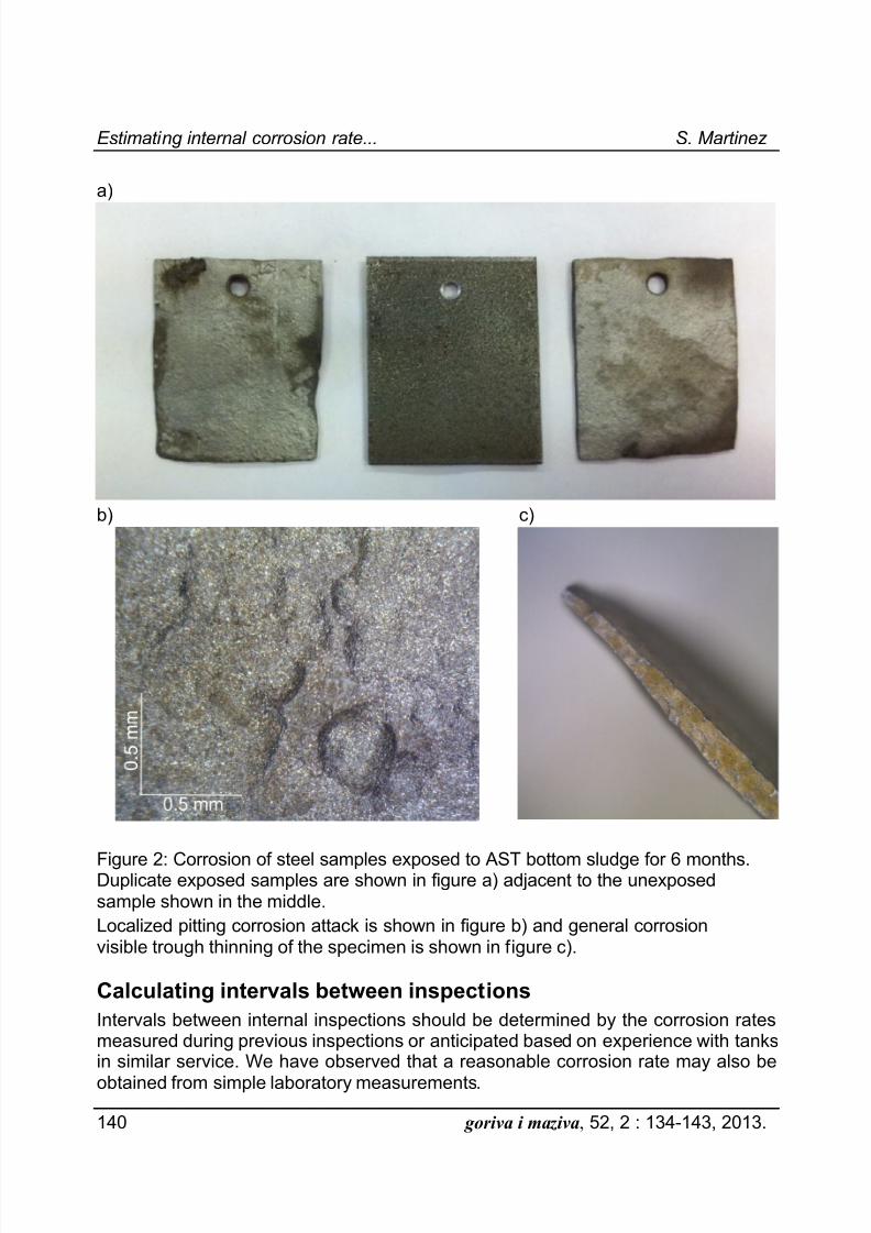
rate in crude oil tank sludge equal to 0.550.05 mm year -1
. The appearance of steelsamples prior and after the 6 months exposure to sludge is shown in Figure 2. Bothuniform and pitting corrosion were observed. Laboratory value was in excellent
agreement whit the average corrosion rate obtained in field that equaled 0.520.2
mm year -1
.
7/21/2019 Martinez ENG
http://slidepdf.com/reader/full/martinez-eng 7/10
Estimating internal corrosion rate... S. Martinez
140 goriva i maziva, 52, 2 : 134-143, 2013.
a)
b) c)
Figure 2: Corrosion of steel samples exposed to AST bottom sludge for 6 months.Duplicate exposed samples are shown in figure a) adjacent to the unexposedsample shown in the middle.
Localized pitting corrosion attack is shown in figure b) and general corrosionvisible trough thinning of the specimen is shown in figure c).
Calculating intervals between inspections
Intervals between internal inspections should be determined by the corrosion ratesmeasured during previous inspections or anticipated based on experience with tanksin similar service. We have observed that a reasonable corrosion rate may also be
obtained from simple laboratory measurements.
7/21/2019 Martinez ENG
http://slidepdf.com/reader/full/martinez-eng 8/10
S. Martinez Estimating internal corrosion rate…
goriva i maziva, 52, 2 : 134-143, 2013. 141
Quantification of the minimum remaining thickness of tank bottoms based on the
results of corrosion rate measurement can be done by the equation: (minimum ili )
bc ip r r r MRT RT RT O StP UP
MRT is the minimum remaining thickness at the end of interval Or . Or is the in-service interval of operation (years to next internal inspection), RT bc is the minimumremaining thickness from bottom side corrosion after repairs, RT ip is the minimumremaining thickness from internal corrosion after repairs; StP r is the maximum rate ofcorrosion on the top side, UP r is the maximum rate of corrosion on the bottom side.
API Standard 653 recognizes the protective capacity of tank bottom lining systemand the cathodic protection system and allows assumption of zero corrosion rate
while the lining is still in perfect condition (StP r = 0) and/or while the cathodicprotection system is working properly (UP r = 0).
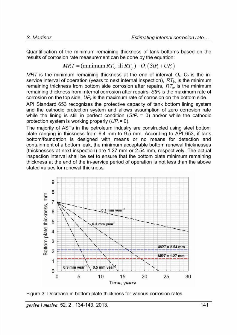
The majority of ASTs in the petroleum industry are constructed using steel bottomplate ranging in thickness from 6.4 mm to 9.5 mm. According to API 653, if tankbottom/foundation is designed with means or no means for detection andcontainment of a bottom leak, the minimum acceptable bottom renewal thicknesses(thicknesses at next inspection) are 1.27 mm or 2.54 mm, respectively. The actualinspection interval shall be set to ensure that the bottom plate minimum remainingthickness at the end of the in-service period of operation is not less than the abovestated values for renewal thickness.
Figure 3: Decrease in bottom plate thickness for various corrosion rates
7/21/2019 Martinez ENG
http://slidepdf.com/reader/full/martinez-eng 9/10
Estimating internal corrosion rate... S. Martinez
142 goriva i maziva, 52, 2 : 134-143, 2013.
I.e. for the initial bottom plate thickness of 7 mm and for various corrosion rates,
MRT as a function of Or is shown in Figure 3. Maximum inspection interval isdetermined by the intersection of the line denoting decrease of the bottom platethickness for a particular corrosion rate and the renewal thickness, RT . Thesignificance of precise determination of corrosion rate for calculation of reliableinspection interval is apparent from the graph. According to API 653, the intervalfrom initial service until the initial internal inspection shall not exceed 10 yearsunless the tank has one of following conditions: bottom thickness 8 mm or greater,cathodic protection or lining. In that case the initial interval may be extended to 12-15 years. For using corrosion rate and (risk based inspection) RBI assessmentprocedures, maximum intervals must not exceed 20 and 25 years, respectively. Forusing RBI assessment procedures and tank with a release prevention barrier,maximum intervals must not exceed 30 years. In Chinese code SY/T 5921 [27] theinitial interval is set to 5-7 years and the maximum of initial inspection interval for thenew tank cannot exceed 10 years. When corrosion rates are not known and similarservice experience is not available, the internal inspection interval must not exceed10 years [4].
Conclusions and recommendations
The accumulation of water at the bottom of ASTs is a primary prerequisite forcorrosion to occur. Corrosion is attributed to the deposition of sludge, the presence
of aggressive agents in the water phase, and, what is considered to be the biggestthreat, the presence of bacterial populations resulting in MIC.
Primary means of keeping the tank’s integrity should be application of corrosionprotection techniques i.e. properly chosen and installed interior bottom lining, fullyfunctional cathodic protection system of the bottom underside and periodic tankdraining. It must be borne in mind that repair works, which often include installationof welded steel patches at the tank’s bottom, may lead to stiffening of the bottomplate and subsequent need for bottom replacement.
In corroding tanks, precise determination (measurement or anticipation) of thecorrosion rate is done trough serious analysis and correct interpretation of field data
and/or performing of supporting laboratory measurements. Knowledge of the truecorrosion rate is essential for calculation of the reliable internal inspection interval.Correctly determined inspection interval is prerequisite for successful balancing thesafe operation requirement and inspection costs as well as the successful longtimeoperation of ASTs.
References
1. GROYSMAN A, Corrosion for everybody , Springer, Dordrecht, 2010, p. 133-146.2. GREENWOOD C., Materials Performance, 51, 8, 14.-15., 2012.3. BARNAWI I.Y., Materials Performance, 51, 3, 3.1-35, 2012.4. API STD 653, Tank Inspection, Repair, Alteration and Reconstruction, 4
th ed., 2009,
Includes Addendum 1, 2010, Addendum 2, 2012.
7/21/2019 Martinez ENG
http://slidepdf.com/reader/full/martinez-eng 10/10
S. Martinez Estimating internal corrosion rate…
goriva i maziva, 52, 2 : 134-143, 2013. 143
5. SHUAI J., HAN K., XU X., Journal of Loss Prevention in the Process Industries, 25, 10,
166-175, 2012.6. YEMASHOVA N.A. et al., Reviews in Environmental Science and Biotechnology , 6, 4, 315-337, 2007.7. ALLSOPP D., KENNETH J.S., GAYLARDE C.C, Introduction to Biodeterioration, 2
nd ed.,
Cambridge University Press, Cambridge, 2004, p. 44-54.8. BEEN J., Report: Comparison of the Corrosivity of Dilbit and Conventional Crude, AlbertaInnovates – Technology Futures, Alberta, 2011.9. GROYSMAN A., ERDMAN N, Corrosion, 56, 12, 1266-1271, 2000.10. GROYSMAN A, Materials Performance, 44, 9, 44–48, 2005.11. API RP 652, Linings of Aboveground Petroleum Storage Tank Bottoms, 3
rd ed., 2005.
12. ANSI/API RP 651, Cathodic Protection of Aboveground Petroleum Storage Tanks, 3rd ed.,
2007.
13. EN ISO 12944, Paints and varnishes -- Corrosion protection of steel structures by protective paint systems – Parts 1-4 and 6-8 , 1998, Part 5 , 2007.14. NORSOK M-501, Surface preparation and protective coating , 6
th ed., 2012.
15. DOC. NO. KOC-P-002 Part 2, Internal Lining of Steel Tanks & Vessels: Part 2: InternalLining of Above Ground Steel Tanks, Rev. 5, 2011.16. 09-SAMSS-067: Qualification Requirements for internal coatings for immersion services,2009.17. NACE No. 10/SSPC-PA 6, Fiberglass-Reinforced Plastic (FRP) Linings Applied toBottoms of Carbon Steel Aboveground Storage Tanks, 2002.18. NACE No. 11/SSPC-PA 8 Thin-Film Organic Linings Applied in New Carbon SteelProcess Vessels, 2003.
19. NACE SP0178, Design, Fabrication, and Surface Finish Practices for Tanks and Vesselsto Be Lined for Immersion Service, 2007.20. API RP 571, Damage mechanisms affecting fixed equipment in the refining industry , 2
nd ed., 2011.
21. EN ISO 8501-3, Preparation of steel substrates before application of paints and related products -- Visual assessment of surface cleanliness -- Part 3: Preparation grades of welds,edges and other areas with surface imperfections, 2007.22. EN 16299, Cathodic protection of external surfaces of above ground storage tank bases incontact with soil or foundations, 2013.23. HEIDERSBACH R., Metallurgy and Corrosion control in Oil and Gas Production,John Wiley & Sons, Inc., Hoboken, 2011.24. VOORDOUW G., Current Opinion in Biotechnology , 22, 401-405, 2011.
25. O’CONNELL M., Journal of Protective Coatings & Linings, 56-63, MARCH 1997.26. GROYSMAN A., SISO R., Materials Performance, 51, 2, 52-56, 2012.27. SY/T 5921, Code for repair of vertical cylindrical welded steel crude oil tanks, 2000.
Author:
Prof. dr. sc. Sanja Martinez, dipl. ing. ([email protected])University of Zagreb, Faculty of Chemical Engineering and Technology,Department of Electrochemistry, Zagreb, Croatia
Received: 27.02.2013.
Accepted: 04.06.2013.