Embed Size (px)
Citation preview
METAL BASED ADDITIVE MANUFACTURING: CHARACTERIZATION OF GEOMETRIC DISTORTION OF POWDER BED FUSION PARTS AFTER HEAT TREATMENT SUBTÍTULO
BEATRIZ BRITES MACEDO DISSERTAÇÃO DE MESTRADO APRESENTADA À FACULDADE DE ENGENHARIA DA UNIVERSIDADE DO PORTO EM JANEIRO DE 2019
M 2019
PROFESSOR MANUEL FERNANDO GONÇALVES VIEIRA
CANDIDATO Código
TÍTULO
DATA __ de ___________ de ________
LOCAL Faculdade de Engenharia da Universidade do Porto – Sala ______ - __:__h
JÚRI Presidente DEMM/FEUP
Arguente DEM/FEUP
Orientador DEMM/FEUP

“Look, if you had one shot, one opportunity, to seize everything you’ve ever
wanted, one moment, would you capture it, or just let it slip?” - Marshall
Bruce Mathers III, 2002
ii
Abstract Additive manufacturing is a process for direct fabrication of both prototypes
and finished parts that has sparked a lot of interest in recent years due to its
unique characteristics. In the specific case of powder bed fusion, a laser is
used to melt metal powder particles according to a digital model, layer upon
layer until a part is fully formed. However one limitation of this method that
still causes concern are the geometric and dimensional distortions suffered by
the built part.
The experimental investigation included the thorough taking of measurements
of parts built using both a vertical and horizontal build, followed by a post
processing heat treatment. Then, measurements were retaken and compared
to the pre-treated state as well as to the design specifications.
This dissertation intends to bring further knowledge about the dimensional
distortion suffered by AM parts before and after post processing.
The first chapter, Literature Review, starts by presenting additive
manufacturing and in particular powder bed fusion, followed by its benefits
and limitations and possible distortion mechanisms. The second chapter,
Experimental Procedure, mentions all the methods used from the production
of the samples used to all carried out operations and measurement taking.
The results are then presented and discussed in chapter three. Conclusions
are presented in chapter four and the report finishes with the fifth chapter,
Future Work.
Keywords Additive manufacturing, Powder Bed Fusion, Metals, Maraging Steel,
Geometric Distortion, Heat Treatment
iii
Resumo Fabrico aditivo é um processo para fabrico direto de protótipos assim como de
peças que tem gerado muito interesse em anos recentes devido às suas
características únicas.
No caso específico da fusão em leito de pó, um laser é utilizado para fundir
partículas de pó metálico de acordo com um modelo digital, camada a
camada até a peça ser completamente formada. No entanto uma limitação
deste método que ainda causa preocupação são as distorções geométricas e
dimensionais sofridas pela peça.
A investigação experimental incluiu a medição das peças que foram fabricadas
na orientação vertical e horizontal, seguidas de um tratamento térmico de
pós processamento.
Depois as medições foram repetidas e comparadas com o estado pré-
tratamento assim como com as especificações do desenho.
Esta dissertação pretende trazer mais conhecimento sobre a distorção
dimensional sofrida pelas peças de fabrico aditivo antes e depois do pós
processamento.
O primeiro capítulo, Revisão Literária, começa por apresentar o fabrico
aditivo e em particular a fusão em leito de pó, seguido dos seus benifícios e
limitações e possíveis meios de distorção.
O segundo capítulo, Procedimento Experimental, menciona todos os métodos
utilizados desde o fabrico das amostras a todas as operações realizadas e
medições. Os resultados são então apresentados e discutidos no terceiro
capítulo. As conclusões são apresentadas no capítulo quatro e o relatório
termina com o quinto capítulo, Trabalho Futuro.
Palavras chave Fabrico aditivo, Fusão em Leito de pó, metais, aço maraging, distorção
geométrica, tratamento térmico
iv
Contents Abstract ........................................................................................... ii
Keywords.......................................................................................... ii
Resumo ........................................................................................... iii
Palavras chave .................................................................................. iii
1 Literature Review .................................................................................................................. 2
1.1 Feedstock materials............................................................................................................ 3
1.2 Residual stresses and distortion ......................................................................................... 3
1.3 Powder Bed Manufacturing ................................................................................................ 3
1.4 Post processing ................................................................................................................... 5
1.5 Benefits .............................................................................................................................. 6
1.6 Limitations .......................................................................................................................... 7
1.7 Distortion Mechanisms....................................................................................................... 8
1.7.1 Distortion between the STL file and the manufactured part ........................................... 8
1.7.2 Distortion of the manufactured part after heat treatment............................................ 10
2 Experimental Procedure ...................................................................................................... 11
2.1 Material and Sample Manufacture ................................................................................... 11
2.1.1 Technical data for the EOS 290 ...................................................................................... 11
2.1.2 Technical data for the maraging steel powder .............................................................. 13
2.2 Procedure ......................................................................................................................... 14
2.2.1 Heat Treatment ............................................................................................................. 17
3 Experimental Results and Discussion................................................................................... 18
3.1 Oven studies ..................................................................................................................... 18
3.2 Oxidation layer ................................................................................................................. 19
3.3 Part measurements .......................................................................................................... 21
3.3.1 Thickness, height and width .......................................................................................... 22
3.3.2 Circular feature .............................................................................................................. 23
3.3.3 Diamond feature ........................................................................................................... 25
3.4 Part defects ...................................................................................................................... 27
3.4.1 Protrusions in the circular feature ................................................................................. 27
3.4.2 Protrusions in the diamond feature............................................................................... 28
4 Conclusions ......................................................................................................................... 30
5 Future Work ........................................................................................................................ 31
References ............................................................................................................................. 32
Annexes............................................................................................................................................35
v
Abbreviations
AM – additive manufacturing
CAD - Computer-aided design
PBF – Powder Bed Fusion
SLS – Selective Laser Sintering
STL - Stereo Lithography Language
Metal based additive manufacturing: Characterization of geometric distortion of Powder Bed Fusion parts after Heat Treatment – B. Macedo
2
1 Literature Review AM processes build three dimensional parts by adding layers of material, one-by-
one, while guided by a digital model. This unique way of building allows for the
production of complex and customized parts directly from its design rather than
needing expensive tooling or machining steps. Intricate parts can be made in a
single step and part count can be reduced by eliminating (or reducing) the need to
assemble multiple components. Parts can even be produced on demand, reducing
inventories and stocks and reducing lead times for critical or obsolete repair parts.
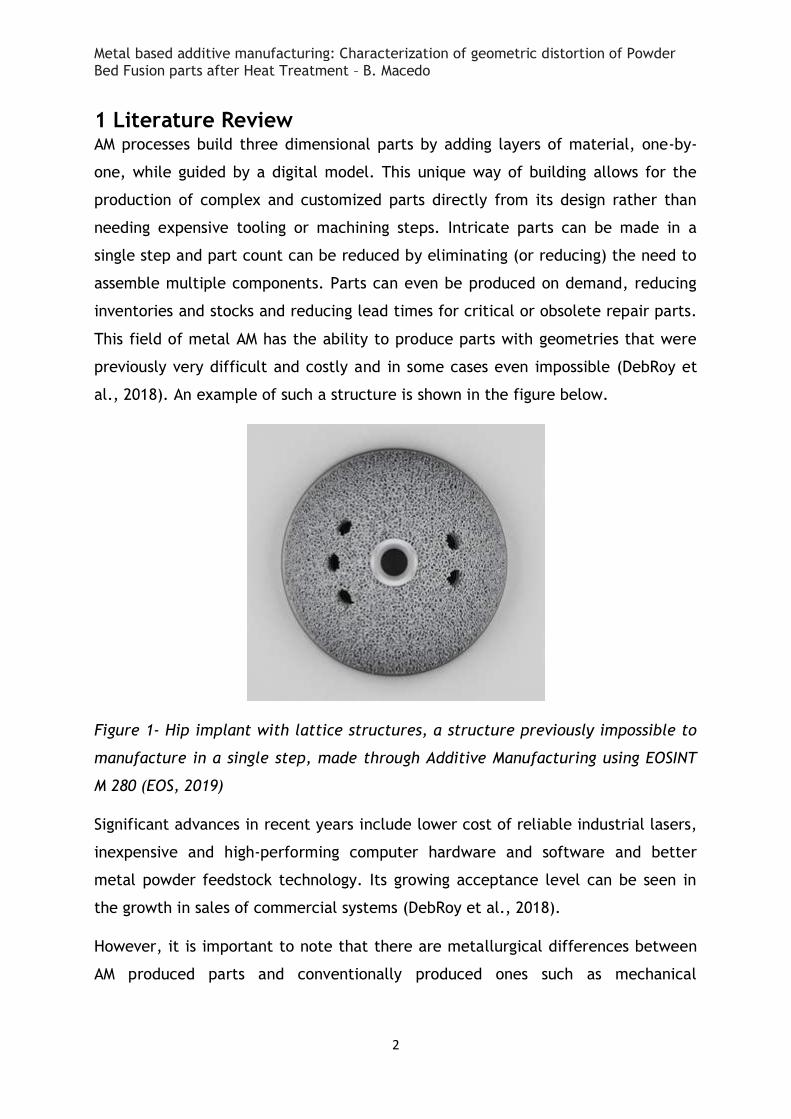
This field of metal AM has the ability to produce parts with geometries that were
previously very difficult and costly and in some cases even impossible (DebRoy et
al., 2018). An example of such a structure is shown in the figure below.
Figure 1- Hip implant with lattice structures, a structure previously impossible to
manufacture in a single step, made through Additive Manufacturing using EOSINT
M 280 (EOS, 2019)
Significant advances in recent years include lower cost of reliable industrial lasers,
inexpensive and high-performing computer hardware and software and better
metal powder feedstock technology. Its growing acceptance level can be seen in
the growth in sales of commercial systems (DebRoy et al., 2018).
However, it is important to note that there are metallurgical differences between
AM produced parts and conventionally produced ones such as mechanical
Metal based additive manufacturing: Characterization of geometric distortion of Powder Bed Fusion parts after Heat Treatment – B. Macedo
3
anisotropy, residual stresses and defects unique to these types of manufacture
(DebRoy et al., 2018).
1.1 Feedstock materials AM processes work by consolidating a feedstock material such as powder, wire or
sheets by melting and solidifying it with the help of a heat source.
Powders are commonly used as feedstock due to the ease of feeding and controlled
melting. However the manufacture of quality powder is still a challenge due to the
spheres’ high surface area and propensity to oxidation. The quality of the finished
parts is heavily dependent on some powder factors such as shape, size distribution,
surface morphology, composition and followability of the powder (Sames et al.,
2016).
The quality of the powder is also dependent on the method used to manufacture it.
A common one is gas atomization where a molten alloy is atomized by the high
pressure flow of an inert gas such as argon or nitrogen (Sames et al., 2016).
1.2 Residual stresses and distortion An inherent consequence of depositing a liquid powder on a relatively cooler
substrate is a very steep temperature gradient, thermal strain and residual
stresses. These can lead to distortion, loss of geometric tolerance and delamination
of layers as well as deterioration of the fatigue performance and fracture
resistance of the final part. (Lewis and Schlienger, 2000 and Mercelis and Kruth,
2006) It needs to be taken into account that the presence of a powder layer pre
placed in the powder bed of the previous layer requires special treatment when
planning temperature gradients since these powdered particles have a different
thermal and mechanical response than consolidated solid metal (King et al., 2015).
1.3 Powder Bed Manufacturing PBF processes were one of the earliest AM processes, and continue to be one of the
most popular and are particularly competitive for low-to-medium volume
geometrically complex parts. Its metal based processes are one of the fastest
growing and most competitive areas of AM. As their allowance of geometric
Metal based additive manufacturing: Characterization of geometric distortion of Powder Bed Fusion parts after Heat Treatment – B. Macedo
4
complexities and excellent material properties make it desirable for aerospace and
biomedical applications, these methods will continue to be improved, decreasing
cost and build time, which will furthermore increase its competitiveness. The
future for PBF remains bright; and it is likely that PBF processes will remain one of
the most common types of AM technologies for the foreseeable future (Gibson et
al., 2010).
All PBF processes share a basic set of characteristics including one or more thermal
sources for inducing fusion between powder particles, a method for controlling
powder fusion to a prescribed region of each layer, and mechanisms for adding and
smoothing powder layers (Gibson et al., 2010).
In PBF, process parameters can be lumped into four categories:
1. Laser-related parameters (laser power, spot size, pulse duration, pulse
frequency, etc.)
2. Scan-related parameters (scan speed, scan spacing, and scan pattern),
3. Powder-related parameters (particle shape, size, and distribution, powder
bed density, layer thickness, material properties, etc.), and
4. Temperature-related parameters (powder bed temperature, powder feeder
temperature, temperature uniformity, etc.).
It should be noted that most of these parameters are strongly interdependent and
are mutually interacting, making it so that the choice of any parameter needs to be
carefully considered against the limitations that it may impose on other parameters
(Gibson et al., 2010).
A container of powder (the powder bed) is in an inert atmosphere (or partial
vacuum) and an energy source (either a laser or an electron beam) is used to scan
each layer of powder to selectively melt the material according to the digital
model. Once this layer has been scanned, the piston holding the powder bed will
descend and more powder will be rolled on top of the container (to spread it
evenly) and a new layer can be formed, by scanning it again with the energy
source. This cycle is then repeated until the full part is formed. The end result of
this process is powder cake and the part is not visible until excess powder is
Metal based additive manufacturing: Characterization of geometric distortion of Powder Bed Fusion parts after Heat Treatment – B. Macedo
5
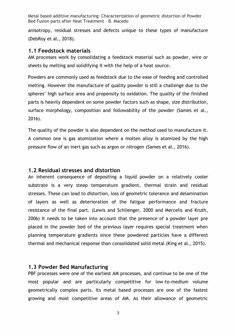
removed (Bhavar et al., 2014). Several parts can be built together so that build
chamber can be fully utilized (Vayre et al., 2012).
Figure 2– Illustration of laser-based powder bed fusion functioning (Bhavar et al.,
2014)
These processes will inherently require support (of same material as part) to avoid
collapse of molten materials in case of overhanging surfaces, to dissipate heat and
prevent distortions. Supports can be generated and modified as per requirements
during pre-processing and they have to be removed by mechanical treatment
during post-processing (Bhavar et al., 2014).
1.4 Post processing Most AM processes require post-processing after part building to prepare the part
for its intended form, fit and/or function. The most common post processing
methods are the following:
1. Support material removal
2. Surface texture improvements
3. Accuracy improvements
4. Aesthetic improvements
5. Preparation for use as a pattern
6. Property improvement using non-thermal techniques
7. Property improvement using thermal treatments
Metal based additive manufacturing: Characterization of geometric distortion of Powder Bed Fusion parts after Heat Treatment – B. Macedo
6
The quality of a given manufacturer's perform post-processing is one of the most
distinguishing characteristics between competing providers (Gibson et al., 2010).
Companies who can efficiently and accurately post-process parts to the desired
specifications can often command higher pricing; whereas, companies which
compete primarily on price may sacrifice post-processing quality in order to reduce
costs, possibly leaving any further post processing to the customer (Gibson et al.,
2010).
Many parts are thermally processed to enhance their properties. This means
primarily heat treatment to form the desired microstructures and/or to relieve
residual stresses. In these instances, recommendations for heat treatment are
developed for the specific metal alloy being employed. In some cases, however,
special heat treatment methods have been developed to retain the fine-grained
microstructure within the AM part while still providing stress relief and ductility
enhancement (Gibson et al., 2010).
Manufacturers often provide their recommendations although these don't always
coincide with the best course of treatment to obtain a particular result. Control of
shrinkage and dimensional accuracy during furnace processing is complicated by
the number of process parameters that must be optimized and the multiple steps
involved. As will be seen in the experimental results, this dimensional accuracy is
difficult to obtain, even when using the manufacturer recommended post
processing techniques (Gibson et al., 2010).
1.5 Benefits SLS (Selective Laser Sintering) processes are a sustainable manufacture system due
to low energy consumption and minimal waste generation (Sreenivasan and Bourell,
2009). There is a high potential to reduce the carbon footprint of parts through
design optimization and reduction in material. An optimal design can reduce a
given part’s weight and material by up to 40%. (Atkins, 2007) Depending on the
final utilisation of these parts, this can represent even greater savings than those
of the part manufacture.
Metal based additive manufacturing: Characterization of geometric distortion of Powder Bed Fusion parts after Heat Treatment – B. Macedo
7
For example, optimizing part design for a long range aircraft cab save up to 100kg
of the total weight, reducing fuel consumption and saving over a metric ton of
carbon dioxide from being produced. A “cradle to grave” life cycle approach is
needed to capture the maximum benefits and it appears that components designed
to explore weight savings hold the greatest potential to impart environmental
benefits (Frazier, 2014).
The particular case of maraging steel has outstanding mechanical properties and an
expedient recommended heat treatment, making it very attractive and allowing for
an accelerated fabrication route. This can offset the high acquisition cost of the
machinery (Frazier, 2014).
1.6 Limitations Supports are required during build to avoid warping, making for costly and time
consuming post processing and sometimes warping might still be present in the
final part. Small features (including internal cooling channels) can usually be
formed without supports; but the part itself is usually the bottom of the build
platform to keep it from warping. As a result, the orientation of the part and the
location of supports are key factors when setting up a build (Gibson et al., 2010).
Accuracy and surface finish of powder-based AM processes are typically inferior to
liquid-based processes. However, accuracy and surface finish are strongly
influenced by the operating conditions and the powder particle size. Finer particle
sizes produce smoother, more accurate parts but are difficult to spread and handle
as well as being more costly. Larger particle sizes facilitate easier powder
processing and delivery, but hurt surface finish, minimum feature size and
minimum layer thickness (Gibson et al., 2010).
Another limitation with PBF processes is that total part construction time can take
longer than other additive manufacturing processes because of the pre-heat and
cool-down cycles involved. However, as is the case with several newer machine
designs, removable build platforms enable preheat and cool-down to occur off-line,
thus enabling much greater machine productivity. However, these increase the cost
of the finished part (Gibson et al., 2010).
Metal based additive manufacturing: Characterization of geometric distortion of Powder Bed Fusion parts after Heat Treatment – B. Macedo
8
Considerable plastic anisotropy has been confirmed in the as-built condition,
specifically for maraging steel MS1, which causes a significant limitation in the
geometries that can be built. This can be reduced by heat treatment but a degree
of anisotropy is likely to remain. In cases where the manufacturers’
recommendations are found to be sub-optimal to obtain the desired results, the
heat treatment parameters will need to be adjusted to meet the property
requirements seeked. These may include further heat treatments, increasing part
cost and the post processing complexity as well as time. This subtracts from the
appeal that this method presented initially (Mooney et al., 2019).
The parts’ anisotropic properties are heavily influenced by build orientation and
manifested through thermal gradients during the melt pool solidification combined
with the layering of powder, planar movement of the heat source and the uniaxial
movement of the build plate. All of these make it very difficult to obtain a
homogenous structure and properties. Furthermore, this can be exacerbated by the
presence of residual stresses or porosity (Mooney et al., 2019).
1.7 Distortion Mechanisms
1.7.1 Distortion between the STL file and the manufactured part All AM parts start as a CAD 3D design, which can be obtained in a number of ways
from using modelling software to scanning an existing part in order to copy it. It is
then necessary to convert this file to a different format in order to produce the
part and the different file types affect part accuracy (Gibson et al., 2010).
After the software conversion is ready, adjustments may be needed. These can be
done by an algorithm or alternatively, manually (Gibson et al., 2010).
STL (Stereo Lithography Language) is one of the more popular formats and widely
used. It consists in slicing the part volume into layers and then slicing those layers
into facets. The size of the facets determines the layer thickness and the
resolution of the design. The higher the number of facets for a given part, the
smaller each facet is, which results in a higher resolution and part accuracy
(Umaras and Tsuzuki, 2017).
Metal based additive manufacturing: Characterization of geometric distortion of Powder Bed Fusion parts after Heat Treatment – B. Macedo
9
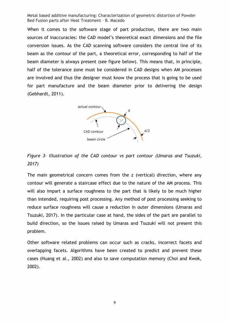
When it comes to the software stage of part production, there are two main
sources of inaccuracies: the CAD model’s theoretical exact dimensions and the file
conversion issues. As the CAD scanning software considers the central line of its
beam as the contour of the part, a theoretical error, corresponding to half of the
beam diameter is always present (see figure below). This means that, in principle,
half of the tolerance zone must be considered in CAD designs when AM processes
are involved and thus the designer must know the process that is going to be used
for part manufacture and the beam diameter prior to delivering the design
(Gebhardt, 2011).
Figure 3– Illustration of the CAD contour vs part contour (Umaras and Tsuzuki,
2017)
The main geometrical concern comes from the z (vertical) direction, where any
contour will generate a staircase effect due to the nature of the AM process. This
will also impart a surface roughness to the part that is likely to be much higher
than intended, requiring post processing. Any method of post processing seeking to
reduce surface roughness will cause a reduction in outer dimensions (Umaras and
Tsuzuki, 2017). In the particular case at hand, the sides of the part are parallel to
build direction, so the issues raised by Umaras and Tsuzuki will not present this
problem.
Other software related problems can occur such as cracks, incorrect facets and
overlapping facets. Algorithms have been created to predict and prevent these
cases (Huang et al., 2002) and also to save computation memory (Choi and Kwok,
2002).
Metal based additive manufacturing: Characterization of geometric distortion of Powder Bed Fusion parts after Heat Treatment – B. Macedo
10
1.7.2 Distortion of the manufactured part after heat treatment Heat conduction is likely to be higher in the build direction rather than the
transversal direction, leading to anisotropy of microstructures (elongated grains). It
would be expected then for the build direction to have an effect on mechanical
properties. The adopted process of post manufacturing heat and surface treatment
dictate the final static and fatigue properties of the part (Meneghetti et al., 2017).
AM doesn’t usually produce final parts and they require post processing to obtain
their final properties. Goals include reduction of porosity and mitigation of inner
residual stress and these are usually achieved through hot isostatic pressure, heat
treatments (the subject of this analysis), micromachining and micro-shot peening
(Meneghetti et al., 2017).
High density is the first goal of process optimization in order to reduce porosity
(Everton et al., 2016). This is because porosity is extremely detrimental to static
and fatigue properties, namely strength. Generally speaking, microstructures of AM
parts are finer than those of parts obtained by other methods such as casting. This
finer microstructure allows for an increase in mechanical properties (yield and
tensile strength) while maintaining ductility (Meneghetti et al., 2017).
Many factors influence the final properties of steel AM parts’ properties: laser
speed, layer thickness and post-aging treatment.
In AM parts, the solidification of subsequent layers of material and large thermal
gradients induce tensile residual stresses, which can cause dimensional tolerances
to be lost after detaching the specimens from the build platform (Meneghetti et
al., 2017).
In AM parts made in nickel-aluminium bronze, it was found that there was a very
obvious anisotropy, with relatively higher strength in the longitudinal direction and
lower strength in the normal direction (Shen et al., 2018) so it would be expected
that something similar would happen in other materials as well.
Metal based additive manufacturing: Characterization of geometric distortion of Powder Bed Fusion parts after Heat Treatment – B. Macedo
11
2 Experimental Procedure
2.1 Material and Sample Manufacture The equipment used to manufacture the samples was an EOS M 290 and the powder
used was the maraging steel “EOS Maraging Steel MS1” provided by the
manufacturer.
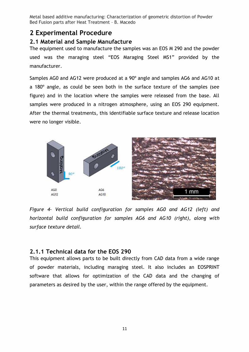
Samples AG0 and AG12 were produced at a 90º angle and samples AG6 and AG10 at
a 180º angle, as could be seen both in the surface texture of the samples (see
figure) and in the location where the samples were released from the base. All
samples were produced in a nitrogen atmosphere, using an EOS 290 equipment.
After the thermal treatments, this identifiable surface texture and release location
were no longer visible.
Figure 4– Vertical build configuration for samples AG0 and AG12 (left) and
horizontal build configuration for samples AG6 and AG10 (right), along with
surface texture detail.
2.1.1 Technical data for the EOS 290 This equipment allows parts to be built directly from CAD data from a wide range
of powder materials, including maraging steel. It also includes an EOSPRINT
software that allows for optimization of the CAD data and the changing of
parameters as desired by the user, within the range offered by the equipment.
Metal based additive manufacturing: Characterization of geometric distortion of Powder Bed Fusion parts after Heat Treatment – B. Macedo
12
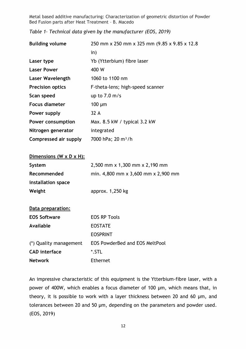
Table 1– Technical data given by the manufacturer (EOS, 2019)
Building volume 250 mm x 250 mm x 325 mm (9.85 x 9.85 x 12.8
in)
Laser type Yb (Ytterbium) fibre laser
Laser Power 400 W
Laser Wavelength 1060 to 1100 nm
Precision optics F-theta-lens; high-speed scanner
Scan speed up to 7.0 m/s
Focus diameter 100 μm
Power supply 32 A
Power consumption Max. 8.5 kW / typical 3.2 kW
Nitrogen generator integrated
Compressed air supply 7000 hPa; 20 m³/h
Dimensions (W x D x H):
System 2,500 mm x 1,300 mm x 2,190 mm
Recommended
installation space
min. 4,800 mm x 3,600 mm x 2,900 mm
Weight approx. 1,250 kg
Data preparation:
EOS Software
Available
(*) Quality management
EOS RP Tools
EOSTATE
EOSPRINT
EOS PowderBed and EOS MeltPool
CAD interface *.STL
Network Ethernet
An impressive characteristic of this equipment is the Ytterbium-fibre laser, with a
power of 400W, which enables a focus diameter of 100 μm, which means that, in
theory, it is possible to work with a layer thickness between 20 and 60 μm, and
tolerances between 20 and 50 μm, depending on the parameters and powder used.
(EOS, 2019)
Metal based additive manufacturing: Characterization of geometric distortion of Powder Bed Fusion parts after Heat Treatment – B. Macedo
13
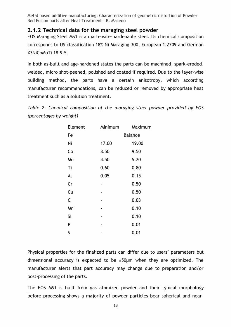
2.1.2 Technical data for the maraging steel powder EOS Maraging Steel MS1 is a martensite-hardenable steel. Its chemical composition
corresponds to US classification 18% Ni Maraging 300, European 1.2709 and German
X3NiCoMoTi 18-9-5.
In both as-built and age-hardened states the parts can be machined, spark-eroded,
welded, micro shot-peened, polished and coated if required. Due to the layer-wise
building method, the parts have a certain anisotropy, which according
manufacturer recommendations, can be reduced or removed by appropriate heat
treatment such as a solution treatment.
Table 2– Chemical composition of the maraging steel powder provided by EOS
(percentages by weight)
Element Minimum Maximum
Fe Balance
Ni 17.00 19.00
Co 8.50 9.50
Mo 4.50 5.20
Ti 0.60 0.80
Al 0.05 0.15
Cr - 0.50
Cu - 0.50
C - 0.03
Mn - 0.10
Si - 0.10
P - 0.01
S - 0.01
Physical properties for the finalized parts can differ due to users’ parameters but
dimensional accuracy is expected to be ±50µm when they are optimized. The
manufacturer alerts that part accuracy may change due to preparation and/or
post-processing of the parts.
The EOS MS1 is built from gas atomized powder and their typical morphology
before processing shows a majority of powder particles bear spherical and near-
Metal based additive manufacturing: Characterization of geometric distortion of Powder Bed Fusion parts after Heat Treatment – B. Macedo
14
spherical morphology, without sharp edges and corners, which allows a free flow of
the powder during layer deposition, which will increase the process efficiency.
(Yasa, 2011 and Kempen, 2011)
The combination between morphology previously described and the small powder
particle diameter will enable a better control of the thermal gradient when the
laser makes the sinterization of the powder, which will assure a better surface to
the produced part, limited mechanical stress during production, better details and
size reduction of production supports.
2.2 Procedure After the parts were produced, measurements were taken. The height and width of
the samples were measured with a calliper. The dimensions of the circular and
square features, as well as the thickness of the samples were too small to
accurately measure with this method
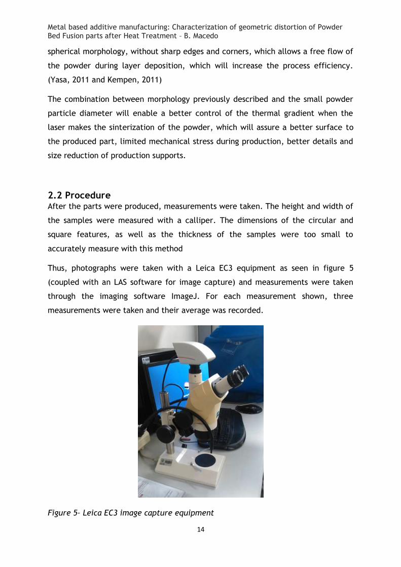
Thus, photographs were taken with a Leica EC3 equipment as seen in figure 5
(coupled with an LAS software for image capture) and measurements were taken
through the imaging software ImageJ. For each measurement shown, three
measurements were taken and their average was recorded.
Figure 5– Leica EC3 image capture equipment
Metal based additive manufacturing: Characterization of geometric distortion of Powder Bed Fusion parts after Heat Treatment – B. Macedo
15
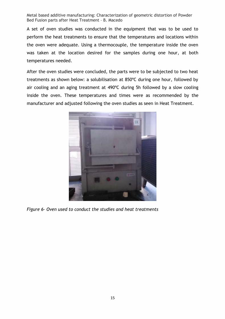
A set of oven studies was conducted in the equipment that was to be used to
perform the heat treatments to ensure that the temperatures and locations within
the oven were adequate. Using a thermocouple, the temperature inside the oven
was taken at the location desired for the samples during one hour, at both
temperatures needed.
After the oven studies were concluded, the parts were to be subjected to two heat
treatments as shown below: a solubilisation at 850ºC during one hour, followed by
air cooling and an aging treatment at 490ºC during 5h followed by a slow cooling
inside the oven. These temperatures and times were as recommended by the
manufacturer and adjusted following the oven studies as seen in Heat Treatment.
Figure 6– Oven used to conduct the studies and heat treatments
Metal based additive manufacturing: Characterization of geometric distortion of Powder Bed Fusion parts after Heat Treatment – B. Macedo
16
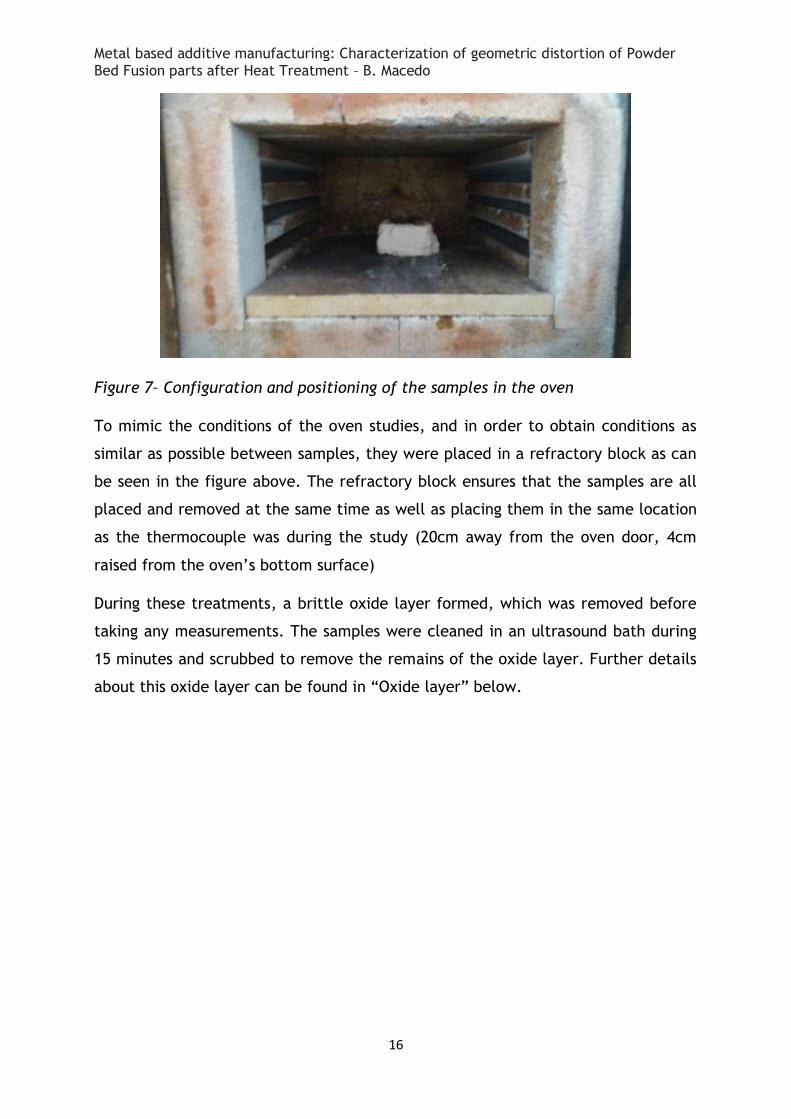
Figure 7– Configuration and positioning of the samples in the oven
To mimic the conditions of the oven studies, and in order to obtain conditions as
similar as possible between samples, they were placed in a refractory block as can
be seen in the figure above. The refractory block ensures that the samples are all
placed and removed at the same time as well as placing them in the same location
as the thermocouple was during the study (20cm away from the oven door, 4cm
raised from the oven’s bottom surface)
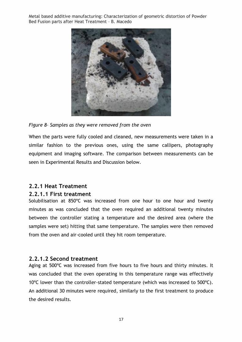
During these treatments, a brittle oxide layer formed, which was removed before
taking any measurements. The samples were cleaned in an ultrasound bath during
15 minutes and scrubbed to remove the remains of the oxide layer. Further details
about this oxide layer can be found in “Oxide layer” below.
Metal based additive manufacturing: Characterization of geometric distortion of Powder Bed Fusion parts after Heat Treatment – B. Macedo
17
Figure 8– Samples as they were removed from the oven
When the parts were fully cooled and cleaned, new measurements were taken in a
similar fashion to the previous ones, using the same callipers, photography
equipment and imaging software. The comparison between measurements can be
seen in Experimental Results and Discussion below.
2.2.1 Heat Treatment
2.2.1.1 First treatment Solubilisation at 850ºC was increased from one hour to one hour and twenty
minutes as was concluded that the oven required an additional twenty minutes
between the controller stating a temperature and the desired area (where the
samples were set) hitting that same temperature. The samples were then removed
from the oven and air-cooled until they hit room temperature.
2.2.1.2 Second treatment Aging at 500ºC was increased from five hours to five hours and thirty minutes. It
was concluded that the oven operating in this temperature range was effectively
10ºC lower than the controller-stated temperature (which was increased to 500ºC).
An additional 30 minutes were required, similarly to the first treatment to produce
the desired results.
Metal based additive manufacturing: Characterization of geometric distortion of Powder Bed Fusion parts after Heat Treatment – B. Macedo
18
3 Experimental Results and Discussion
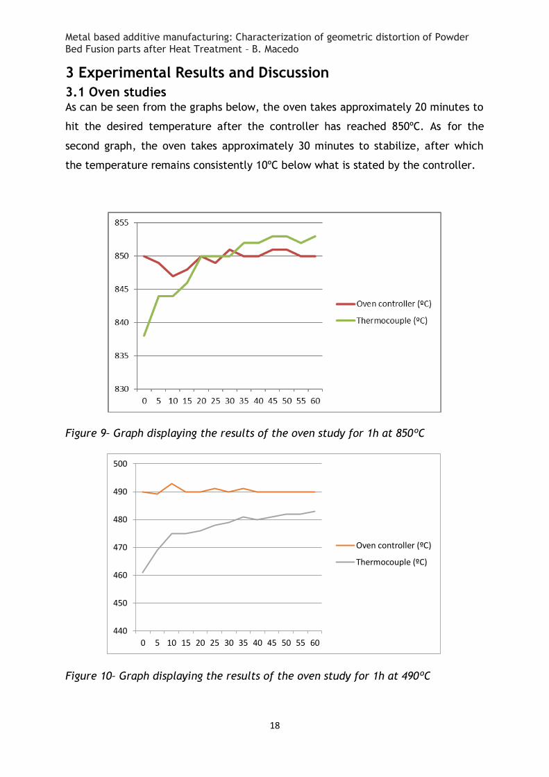
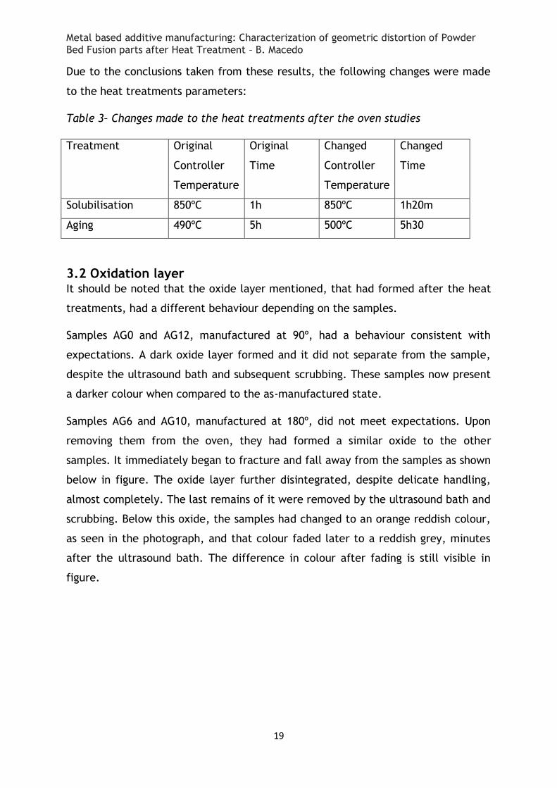
3.1 Oven studies As can be seen from the graphs below, the oven takes approximately 20 minutes to
hit the desired temperature after the controller has reached 850ºC. As for the
second graph, the oven takes approximately 30 minutes to stabilize, after which
the temperature remains consistently 10ºC below what is stated by the controller.
Figure 9– Graph displaying the results of the oven study for 1h at 850ºC
Figure 10– Graph displaying the results of the oven study for 1h at 490ºC
440
450
460
470
480
490
500
0 5 10 15 20 25 30 35 40 45 50 55 60
Oven controller (ºC)
Thermocouple (ºC)
Metal based additive manufacturing: Characterization of geometric distortion of Powder Bed Fusion parts after Heat Treatment – B. Macedo
19
Due to the conclusions taken from these results, the following changes were made
to the heat treatments parameters:
Table 3– Changes made to the heat treatments after the oven studies
Treatment Original
Controller
Temperature
Original
Time
Changed
Controller
Temperature
Changed
Time
Solubilisation 850ºC 1h 850ºC 1h20m
Aging 490ºC 5h 500ºC 5h30
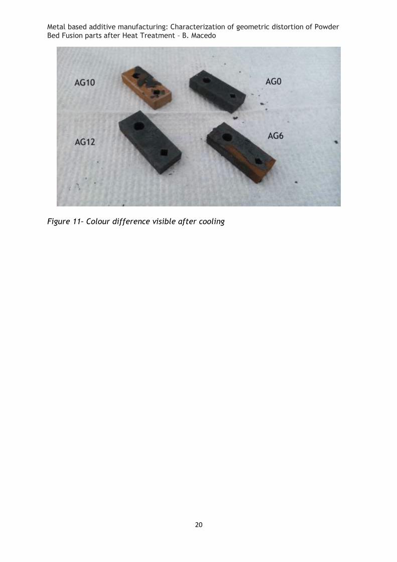
3.2 Oxidation layer It should be noted that the oxide layer mentioned, that had formed after the heat
treatments, had a different behaviour depending on the samples.
Samples AG0 and AG12, manufactured at 90º, had a behaviour consistent with
expectations. A dark oxide layer formed and it did not separate from the sample,
despite the ultrasound bath and subsequent scrubbing. These samples now present
a darker colour when compared to the as-manufactured state.
Samples AG6 and AG10, manufactured at 180º, did not meet expectations. Upon
removing them from the oven, they had formed a similar oxide to the other
samples. It immediately began to fracture and fall away from the samples as shown
below in figure. The oxide layer further disintegrated, despite delicate handling,
almost completely. The last remains of it were removed by the ultrasound bath and
scrubbing. Below this oxide, the samples had changed to an orange reddish colour,
as seen in the photograph, and that colour faded later to a reddish grey, minutes
after the ultrasound bath. The difference in colour after fading is still visible in
figure.
Metal based additive manufacturing: Characterization of geometric distortion of Powder Bed Fusion parts after Heat Treatment – B. Macedo
20
Figure 11– Colour difference visible after cooling
Metal based additive manufacturing: Characterization of geometric distortion of Powder Bed Fusion parts after Heat Treatment – B. Macedo
21
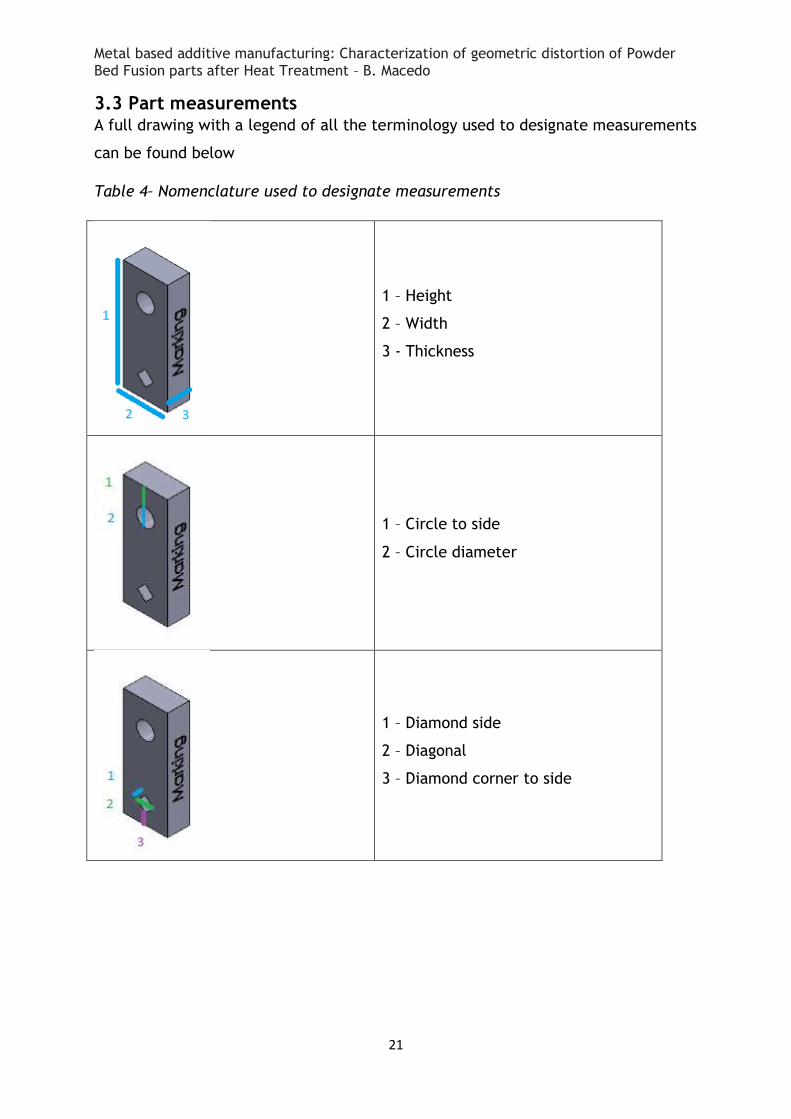
3.3 Part measurements A full drawing with a legend of all the terminology used to designate measurements
can be found below
Table 4– Nomenclature used to designate measurements
1 – Height
2 – Width
3 - Thickness
1 – Circle to side
2 – Circle diameter
1 – Diamond side
2 – Diagonal
3 – Diamond corner to side
Metal based additive manufacturing: Characterization of geometric distortion of Powder Bed Fusion parts after Heat Treatment – B. Macedo
22
3.3.1 Thickness, height and width
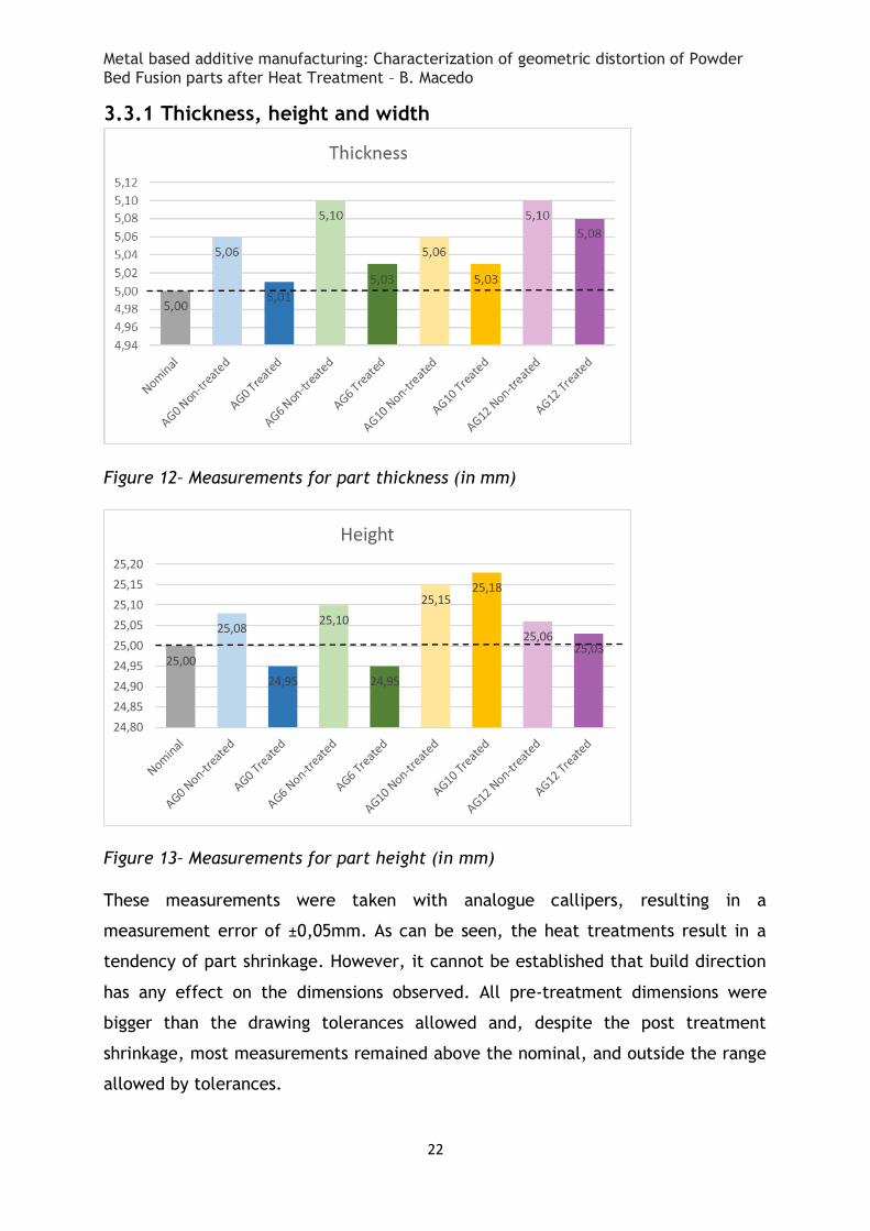
Figure 12– Measurements for part thickness (in mm)
Figure 13– Measurements for part height (in mm)
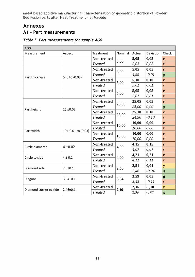
These measurements were taken with analogue callipers, resulting in a
measurement error of ±0,05mm. As can be seen, the heat treatments result in a
tendency of part shrinkage. However, it cannot be established that build direction
has any effect on the dimensions observed. All pre-treatment dimensions were
bigger than the drawing tolerances allowed and, despite the post treatment
shrinkage, most measurements remained above the nominal, and outside the range
allowed by tolerances.
25,00
25,08
24,95
25,10
24,95
25,15 25,18
25,06 25,03
24,80
24,85
24,90
24,95
25,00
25,05
25,10
25,15
25,20
Height
Metal based additive manufacturing: Characterization of geometric distortion of Powder Bed Fusion parts after Heat Treatment – B. Macedo
23
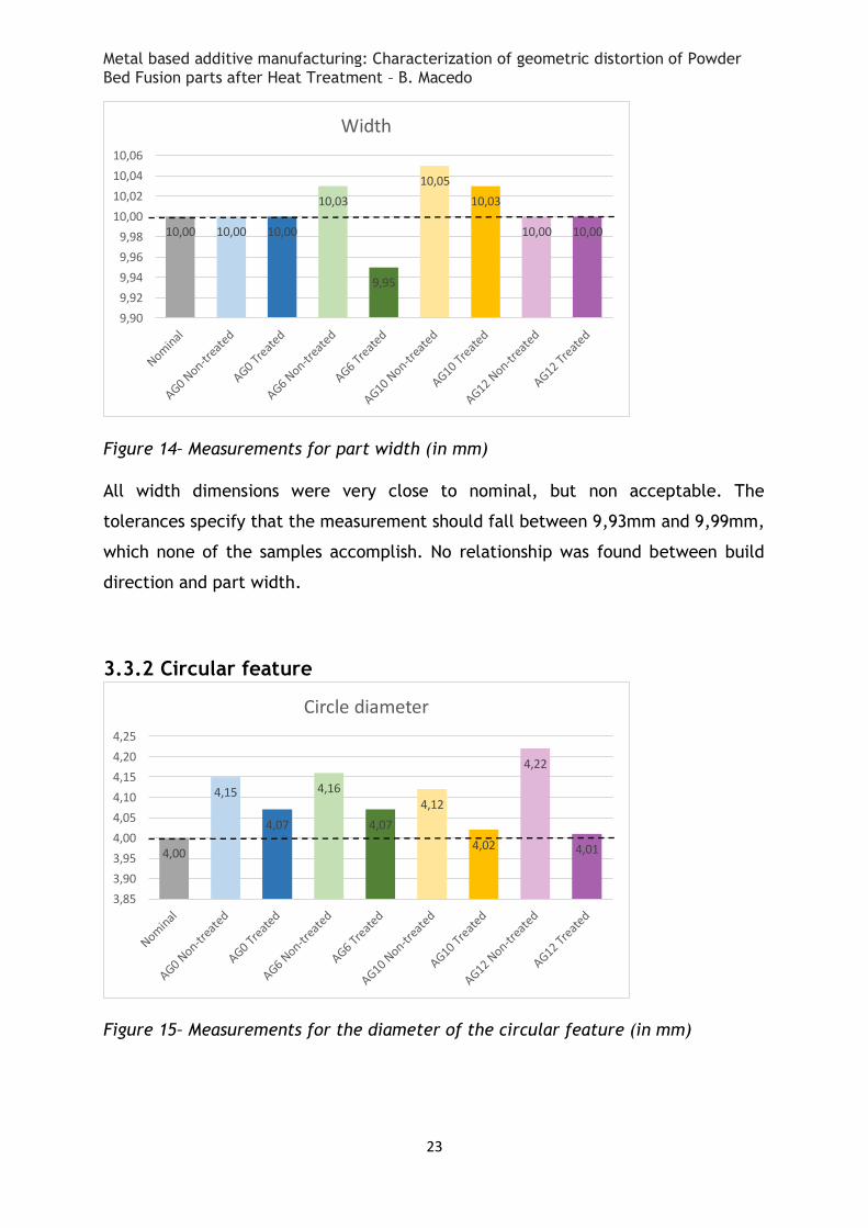
Figure 14– Measurements for part width (in mm)
All width dimensions were very close to nominal, but non acceptable. The
tolerances specify that the measurement should fall between 9,93mm and 9,99mm,
which none of the samples accomplish. No relationship was found between build
direction and part width.
3.3.2 Circular feature
Figure 15– Measurements for the diameter of the circular feature (in mm)
10,00 10,00 10,00
10,03
9,95
10,05
10,03
10,00 10,00
9,90
9,92
9,94
9,96
9,98
10,00
10,02
10,04
10,06
Width
4,00
4,15
4,07
4,16
4,07
4,12
4,02
4,22
4,01
3,85
3,90
3,95
4,00
4,05
4,10
4,15
4,20
4,25
Circle diameter
Metal based additive manufacturing: Characterization of geometric distortion of Powder Bed Fusion parts after Heat Treatment – B. Macedo
24
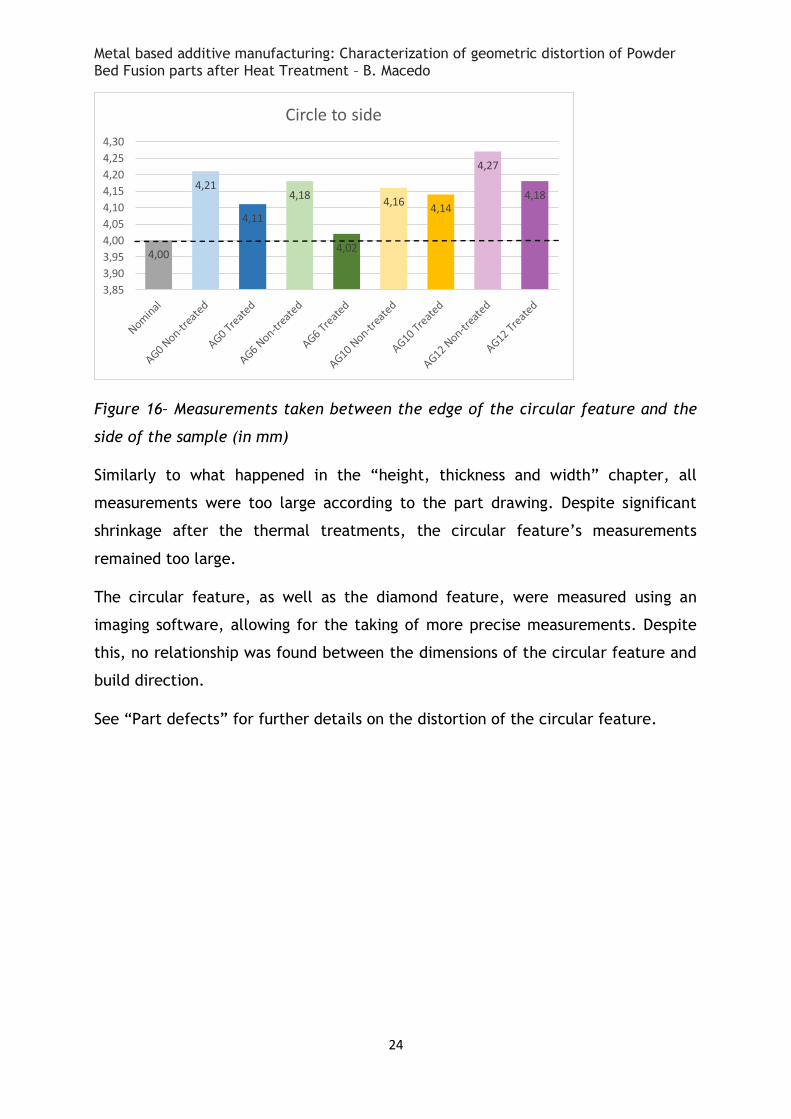
Figure 16– Measurements taken between the edge of the circular feature and the
side of the sample (in mm)
Similarly to what happened in the “height, thickness and width” chapter, all
measurements were too large according to the part drawing. Despite significant
shrinkage after the thermal treatments, the circular feature’s measurements
remained too large.
The circular feature, as well as the diamond feature, were measured using an
imaging software, allowing for the taking of more precise measurements. Despite
this, no relationship was found between the dimensions of the circular feature and
build direction.
See “Part defects” for further details on the distortion of the circular feature.
4,00
4,21
4,11
4,18
4,02
4,16 4,14
4,27
4,18
3,85
3,90
3,95
4,00
4,05
4,10
4,15
4,20
4,25
4,30
Circle to side
Metal based additive manufacturing: Characterization of geometric distortion of Powder Bed Fusion parts after Heat Treatment – B. Macedo
25
3.3.3 Diamond feature
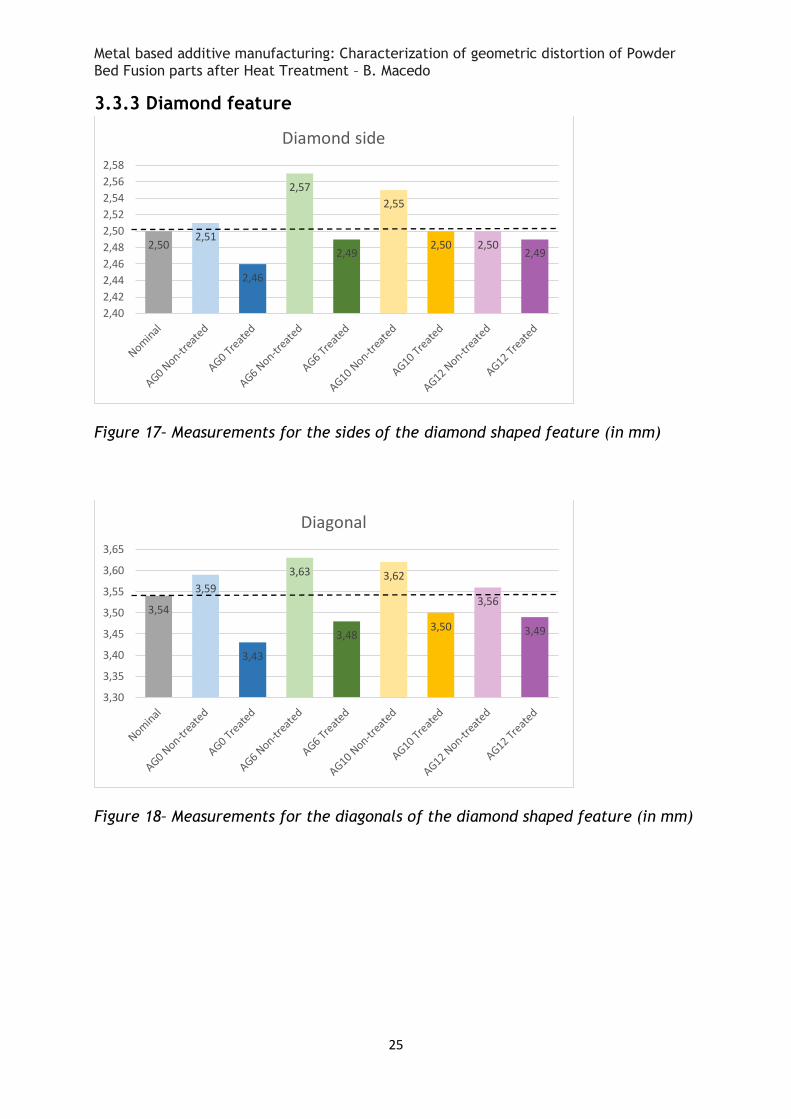
Figure 17– Measurements for the sides of the diamond shaped feature (in mm)
Figure 18– Measurements for the diagonals of the diamond shaped feature (in mm)
2,50 2,51
2,46
2,57
2,49
2,55
2,50 2,50 2,49
2,40
2,42
2,44
2,46
2,48
2,50
2,52
2,54
2,56
2,58
Diamond side
3,54
3,59
3,43
3,63
3,48
3,62
3,50
3,56
3,49
3,30
3,35
3,40
3,45
3,50
3,55
3,60
3,65
Diagonal
Metal based additive manufacturing: Characterization of geometric distortion of Powder Bed Fusion parts after Heat Treatment – B. Macedo
26
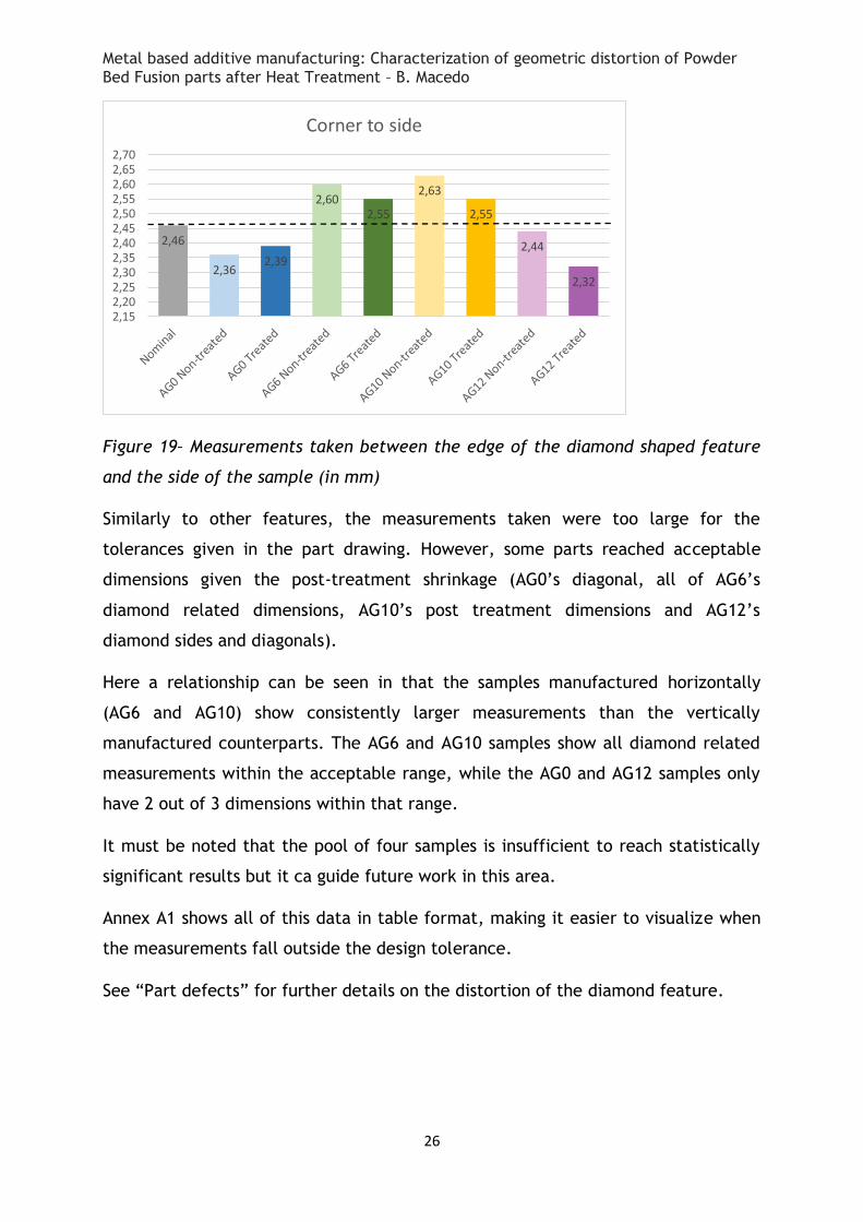
Figure 19– Measurements taken between the edge of the diamond shaped feature
and the side of the sample (in mm)
Similarly to other features, the measurements taken were too large for the
tolerances given in the part drawing. However, some parts reached acceptable
dimensions given the post-treatment shrinkage (AG0’s diagonal, all of AG6’s
diamond related dimensions, AG10’s post treatment dimensions and AG12’s
diamond sides and diagonals).
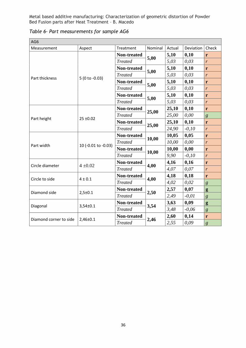
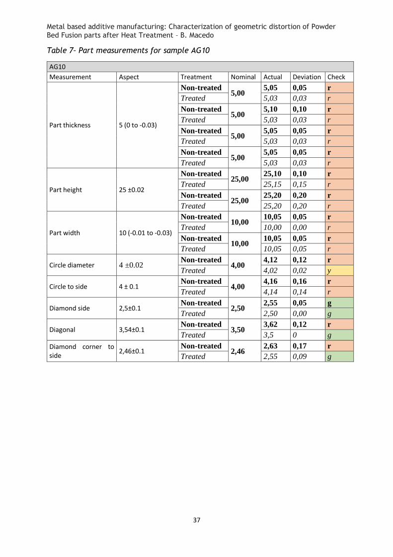
Here a relationship can be seen in that the samples manufactured horizontally
(AG6 and AG10) show consistently larger measurements than the vertically
manufactured counterparts. The AG6 and AG10 samples show all diamond related
measurements within the acceptable range, while the AG0 and AG12 samples only
have 2 out of 3 dimensions within that range.
It must be noted that the pool of four samples is insufficient to reach statistically
significant results but it ca guide future work in this area.
Annex A1 shows all of this data in table format, making it easier to visualize when
the measurements fall outside the design tolerance.
See “Part defects” for further details on the distortion of the diamond feature.
2,46
2,36 2,39
2,60 2,55
2,63
2,55
2,44
2,32
2,152,202,252,302,352,402,452,502,552,602,652,70
Corner to side
Metal based additive manufacturing: Characterization of geometric distortion of Powder Bed Fusion parts after Heat Treatment – B. Macedo
27
3.4 Part defects A complete set of the pictures comparing the protrusions pre and post thermal
treatment can be found in annexes A2 and A3. It can be seen that the features and
respective protrusions show no changes before and after the thermal treatments.
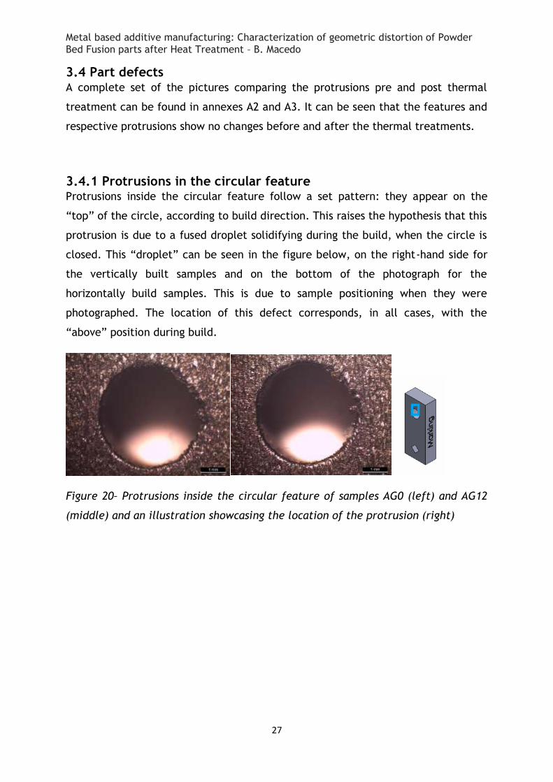
3.4.1 Protrusions in the circular feature Protrusions inside the circular feature follow a set pattern: they appear on the
“top” of the circle, according to build direction. This raises the hypothesis that this
protrusion is due to a fused droplet solidifying during the build, when the circle is
closed. This “droplet” can be seen in the figure below, on the right-hand side for
the vertically built samples and on the bottom of the photograph for the
horizontally build samples. This is due to sample positioning when they were
photographed. The location of this defect corresponds, in all cases, with the
“above” position during build.
Figure 20– Protrusions inside the circular feature of samples AG0 (left) and AG12
(middle) and an illustration showcasing the location of the protrusion (right)
Metal based additive manufacturing: Characterization of geometric distortion of Powder Bed Fusion parts after Heat Treatment – B. Macedo
28
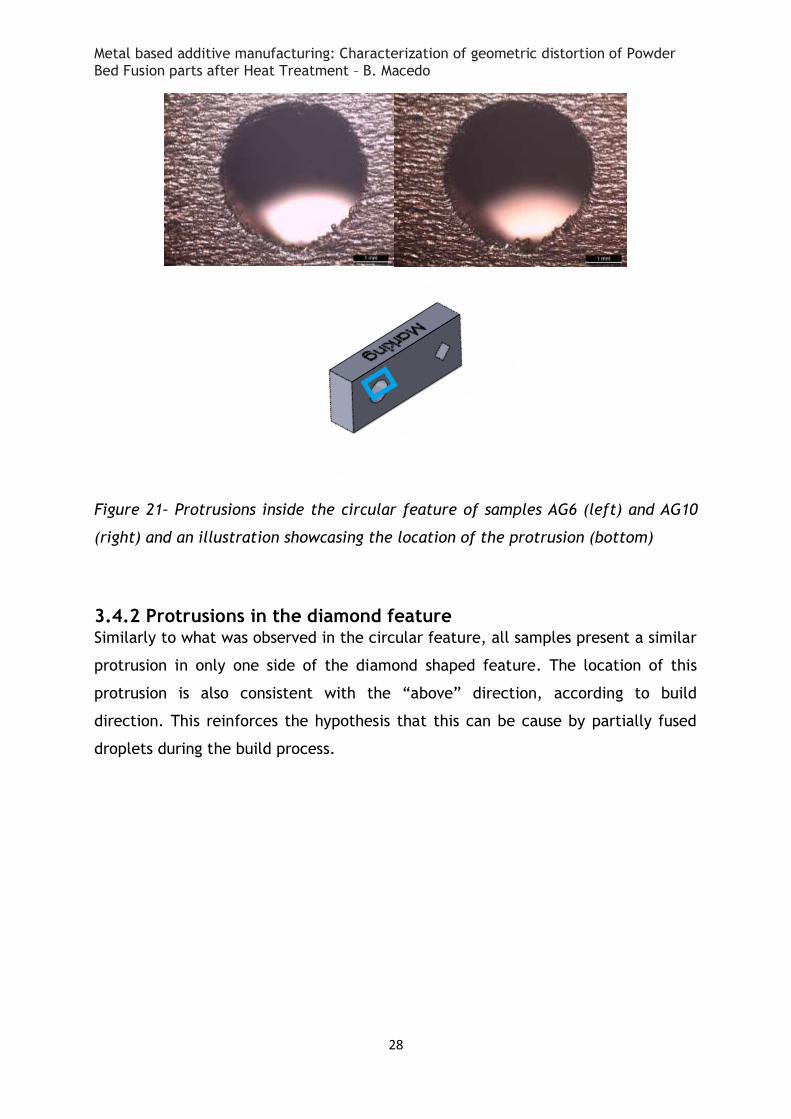
Figure 21– Protrusions inside the circular feature of samples AG6 (left) and AG10
(right) and an illustration showcasing the location of the protrusion (bottom)
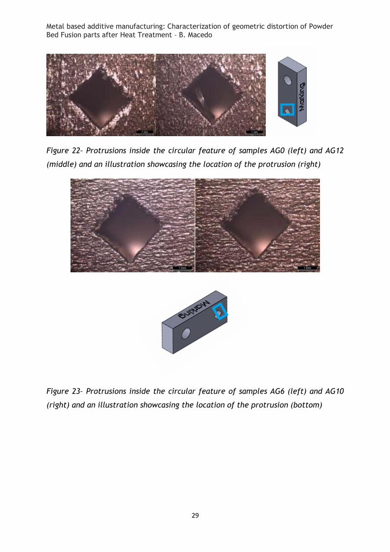
3.4.2 Protrusions in the diamond feature Similarly to what was observed in the circular feature, all samples present a similar
protrusion in only one side of the diamond shaped feature. The location of this
protrusion is also consistent with the “above” direction, according to build
direction. This reinforces the hypothesis that this can be cause by partially fused
droplets during the build process.
Metal based additive manufacturing: Characterization of geometric distortion of Powder Bed Fusion parts after Heat Treatment – B. Macedo
29
Figure 22– Protrusions inside the circular feature of samples AG0 (left) and AG12
(middle) and an illustration showcasing the location of the protrusion (right)
Figure 23– Protrusions inside the circular feature of samples AG6 (left) and AG10
(right) and an illustration showcasing the location of the protrusion (bottom)
Metal based additive manufacturing: Characterization of geometric distortion of Powder Bed Fusion parts after Heat Treatment – B. Macedo
30
4 Conclusions In this study, the goal was to evaluate the geometric distortion suffered by metal
based additive manufactured parts, specifically maraging steel, processed through
direct metal laser sintering (DMLS).
After manufacture, the parts were subjected through post processing heat
treatments as recommended by the manufacturer and then the dimensions before
and after the study were compared.
Regarding dimensional analysis, nearly all measurements fell outside of design
specifications and tolerances. After heat treatment, most dimensions shrank, still
falling outside of requirements and tolerances.
From this small sample of 4 parts, no relationship could be found between build
direction and any geometric distortion.
A small droplet shaped defect was found on every hollow feature, circular or
diamond shape, consistent with the downwards direction, according to direction of
build. This may be due to a fused droplet during manufacture. This distorts the
intended shape of a perfectly smooth circle or diamond.
Metal based additive manufacturing: Characterization of geometric distortion of Powder Bed Fusion parts after Heat Treatment – B. Macedo
31
5 Future Work
This research has raised many interesting points worth exploring in order to
gain further knowledge of this subject. The following are suggested:
Determination of the oxide’s composition
Determination of whether the release of oxide form the sample is related to
the build direction. It seems like it will be related, but further samples are
needed to ensure statistical significance
Dilatometry studies to search for phase changes during the treatment to
explain the shrinkage
Comparative studies between measurements obtained by this method of
photography and imaging and other methods of measurement capture
Metal based additive manufacturing: Characterization of geometric distortion of Powder Bed Fusion parts after Heat Treatment – B. Macedo
32
References Atkins, 2017 ATKINS, “Manufacturing a Low Carbon Footprint”,
Loughborough University Project number N0012J,
2007
Bhavar et al., 2014 V. Bhavar, P. Kattire, V. Patil, S. Khot, K. Gujar, R.
Singh. 2014. “A Review on Powder Bed Fusion
Technology of Metal Additive Manufacturing” 4th
International conference and exhibition on Additive
Manufacturing Technologies-AM-2014, Septeber 1 &2
,2014, Banglore, India
Choi and Kwok, 2002 S. H. Choi and K. T. Kwok. 2002. “A tolerant slicing
algorithm for layered manufacturing”. Rapid
Prototyping J 8 (3), 161-179
DebRoy et al., 2018 T. DebRoy, H. L. Wei, J. S. Zuback, T. Mukherjee, J.
W. Elmer, J. O. Milewski, A. M. Beese, A. Wilson-
Heid, A. De, W. Zhang. 2018. “Additive
manufacturing of metallic components – Process,
structure and properties”. Progress in materials
Science 92, 112-224
EOS, 2019 EOS Metal Materials for Additive Manufacturing
https://www.eos.info/material-m
(accessed January 16, 2019)
EOS, 2019 EOS M 290 Industrial 3D Printed parts from metal
materials
https://www.eos.info/eos-m290
(accessed January 16, 2019)
Everton et al., 2016 S. K. Everton, M. Hirsch, P. Stavroulakis, R. K.
Leach, A. T. Clare. 2016. “Review of in-situ process
monitoring and in-situ metrology for metal additive
manufacturing”. Materials & Design 95, 431-445
Frazier, 2014 William E. Frazier. 2014. “Metal Additive
Manufacturing: A Review”. Journal of Materials
Engineering and Performance 23, 1917-1928
Metal based additive manufacturing: Characterization of geometric distortion of Powder Bed Fusion parts after Heat Treatment – B. Macedo
33
Gebhardt, 2011 A. Gebhardt. 2011. “Understanding Additive
Manufacturing, Rapid Prototyping, Rapid Tooling,
Rapid Manufacturing”. Hanser Publishers, Munich
Gibson et al., 2010 Ian Gibson, David W. Rosen and Brent Stucker. 2010.
“Additive Manufacturing Technologies, Rapid
Prototyping to Direct Digital Manufacturing”,
Springer, New York
Huang et al., 2002 S. H. Huang, L. C. Zhang and M. Han. 2002. “An
effective error-tolerance slicing algorithm for STL
files”. Int J Adv Manuf Tech 20 (5), 363-367
Kempen et al., 2011 K. Kempen, E. Yasa, L. Thijs, J.-P. Kruth, J. Van
Humbeeck. 2011. “Microstructure and mechanical
properties of Selective Laser Melted 18Ni-300 steel”.
Physics Procedia 12, 255-263
King et al., 2015 W. E. King, A. T. Anderson, R. M. Ferencz, N. E.
Hodge, C. Kamath, S.A. Khairallah et al. 2015.
“Laser powder bed fusion additive manufacturing of
metals: physics, computation and materials
challenges”. Appl Phys Rev 2 (4)
Lewis and Schlienger,
2000
G. K. lewis and E. Schlienger. 2000. “Practical
considerations and capabilities for laser assisted
direct metal deposition”. Mater Des 21 (4), 417-723
Meneghetti et al.,
2017
G. Meneghetti, D. Rigon, D. Cozzi, W. Waldhauser,
M. Dabalà. 2017. “Influence of build orientation on
static and axial fatigue properties of maraging steel
specimens produced by additive manufacturing”.
Procedia Structural Integrity 7, 149-157
Mercelis and Kruth,
2006
P. Mercelis and J. P. Kruth. 2006. “Residual stresses
in selective laser sintering and selective laser
melting”. Rapid Prototyp J 12 (5), 254-265
Mooney et al., 2019 Barry Mooney, Kyriakos I. Kourousis, Ramesh
Raghavendra. 2019. “Plastic anisotropy of additively
manufactured maraging steel: Influence of the build
Metal based additive manufacturing: Characterization of geometric distortion of Powder Bed Fusion parts after Heat Treatment – B. Macedo
34
orientation and heat treatments”. Additive
Manufacturing 25, 19-31
Sames et al., 2016 W. J. Sames, F. A. List, S. Pannala, R. R. Dehoff, S.
S. Babu. 2016. “The metallurgy and processing of
metal additive manufacturing”. Int Mat Rev 61 (5),
315-360
Shen et al., 2018 Chen Shen, Zengxi Pan, Donghong Ding, Lei Yuan,
Ning Nie, Ying Wang, Dongzhi Luo, Dominic Cuiuri,
Stephen van Duin, Huijun Li. 2018. “The influence of
post-production heat treatment on the multi-
directional properties of nickel-aluminum bronze
alloy fabricated using wire-arc additive
manufacturing process”. Additive Manufacturing 23,
411-421
Sreenivasan and
Bourell, 2009
R. Sreenivasan and D. Bourell. 2009. “Sustainability
Study in Selective Laser Sintering: An energy
Perspective, Conference Proceedings”. University of
Texas at Austin 257-265
Umaras and Tsuzuki,
2017
Eduardo Umaras and Marcos S. G. Tsuzuki. 2017.
“Additive Manufacturing – Considerations on
Geometric Accuracy and Factors of Influence”. IFAC
PapersOnLine 50-1, 14940-14945
Vayre et al., 2012 B. Vayre, Frederic Vignat and Francois Villeneuve
“Metallic additive manufacturing: State-of-the-art
review and prospects” Grenoble, France, January
2012.
Yasa et al., 2011 E. Yasa, J.P. Kruth, J. Deckers. 2011.
“Manufacturing by combining Selective Laser Melting
and Selective Laser Erosion/laser re-melting”. CIRP
Annals - Manufacturing Technology 60, 263-266
Metal based additive manufacturing: Characterization of geometric distortion of Powder Bed Fusion parts after Heat Treatment – B. Macedo
35
Annexes A1 – Part measurements
Table 5– Part measurements for sample AG0
AG0
Measurement Aspect Treatment Nominal Actual Deviation Check
Part thickness 5 (0 to -0.03)
Non-treated 5,00
5,05 0,05 r
Treated 5,03 0,03 r
Non-treated 5,00
5,05 0,05 r
Treated 4,99 -0,01 g
Non-treated 5,00
5,10 0,10 r
Treated 5,01 0,01 r
Non-treated 5,00
5,05 0,05 r
Treated 5,01 0,01 r
Part height 25 ±0.02
Non-treated 25,00
25,05 0,05 r
Treated 25,00 0,00 g
Non-treated 25,00
25,10 0,10 r
Treated 24,90 -0,10 r
Part width 10 (-0.01 to -0.03)
Non-treated 10,00
10,00 0,00 r
Treated 10,00 0,00 r
Non-treated 10,00
10,00 0,00 r
Treated 10,00 0,00 r
Circle diameter 4 ±0.02 Non-treated
4,00 4,15 0.15 r
Treated 4,07 0,07 r
Circle to side 4 ± 0.1 Non-treated
4,00 4,21 0,21 r
Treated 4,11 0,11 r
Diamond side 2,5±0.1 Non-treated
2,50 2,51 0,01 y
Treated 2,46 -0,04 g
Diagonal 3,54±0.1 Non-treated
3,54 3,59 0,05 g
Treated 3,43 -0,11 r
Diamond corner to side 2,46±0.1 Non-treated
2,46 2,36 -0,10 y
Treated 2,39 -0,07 g
Metal based additive manufacturing: Characterization of geometric distortion of Powder Bed Fusion parts after Heat Treatment – B. Macedo
36
Table 6– Part measurements for sample AG6
AG6
Measurement Aspect Treatment Nominal Actual Deviation Check
Part thickness 5 (0 to -0.03)
Non-treated 5,00
5,10 0,10 r
Treated 5,03 0,03 r
Non-treated 5,00
5,10 0,10 r
Treated 5,03 0,03 r
Non-treated 5,00
5,10 0,10 r
Treated 5,03 0,03 r
Non-treated 5,00
5,10 0,10 r
Treated 5,03 0,03 r
Part height 25 ±0.02
Non-treated 25,00
25,10 0,10 r
Treated 25,00 0,00 g
Non-treated 25,00
25,10 0,10 r
Treated 24,90 -0,10 r
Part width 10 (-0.01 to -0.03)
Non-treated 10,00
10,05 0,05 r
Treated 10,00 0,00 r
Non-treated 10,00
10,00 0,00 r
Treated 9,90 -0,10 r
Circle diameter 4 ±0.02 Non-treated
4,00 4,16 0,16 r
Treated 4,07 0,07 r
Circle to side 4 ± 0.1 Non-treated
4,00 4,18 0,18 r
Treated 4,02 0,02 g
Diamond side 2,5±0.1 Non-treated
2,50 2,57 0,07 g
Treated 2,49 -0,01 g
Diagonal 3,54±0.1 Non-treated
3,54 3,63 0,09 g
Treated 3,48 -0,06 g
Diamond corner to side 2,46±0.1 Non-treated
2,46 2,60 0,14 r
Treated 2,55 0,09 g
Metal based additive manufacturing: Characterization of geometric distortion of Powder Bed Fusion parts after Heat Treatment – B. Macedo
37
Table 7– Part measurements for sample AG10
AG10
Measurement Aspect Treatment Nominal Actual Deviation Check
Part thickness 5 (0 to -0.03)
Non-treated 5,00
5,05 0,05 r
Treated 5,03 0,03 r
Non-treated 5,00
5,10 0,10 r
Treated 5,03 0,03 r
Non-treated 5,00
5,05 0,05 r
Treated 5,03 0,03 r
Non-treated 5,00
5,05 0,05 r
Treated 5,03 0,03 r
Part height 25 ±0.02
Non-treated 25,00
25,10 0,10 r
Treated 25,15 0,15 r
Non-treated 25,00
25,20 0,20 r
Treated 25,20 0,20 r
Part width 10 (-0.01 to -0.03)
Non-treated 10,00
10,05 0,05 r
Treated 10,00 0,00 r
Non-treated 10,00
10,05 0,05 r
Treated 10,05 0,05 r
Circle diameter 4 ±0.02 Non-treated
4,00 4,12 0,12 r
Treated 4,02 0,02 y
Circle to side 4 ± 0.1 Non-treated
4,00 4,16 0,16 r
Treated 4,14 0,14 r
Diamond side 2,5±0.1 Non-treated
2,50 2,55 0,05 g
Treated 2,50 0,00 g
Diagonal 3,54±0.1 Non-treated
3,50 3,62 0,12 r
Treated 3,5 0 g
Diamond corner to side
2,46±0.1 Non-treated
2,46 2,63 0,17 r
Treated 2,55 0,09 g
Metal based additive manufacturing: Characterization of geometric distortion of Powder Bed Fusion parts after Heat Treatment – B. Macedo
38
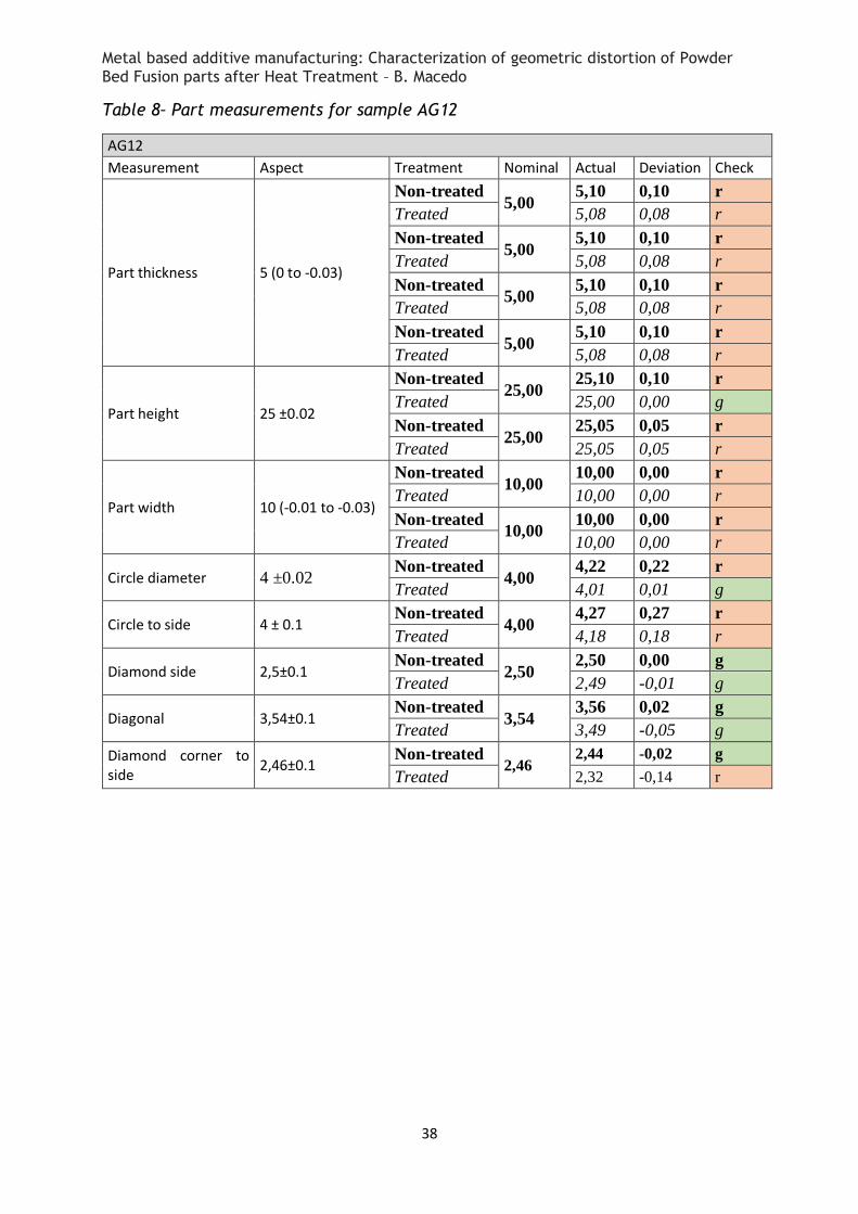
Table 8– Part measurements for sample AG12
AG12
Measurement Aspect Treatment Nominal Actual Deviation Check
Part thickness 5 (0 to -0.03)
Non-treated 5,00
5,10 0,10 r
Treated 5,08 0,08 r
Non-treated 5,00
5,10 0,10 r
Treated 5,08 0,08 r
Non-treated 5,00
5,10 0,10 r
Treated 5,08 0,08 r
Non-treated 5,00
5,10 0,10 r
Treated 5,08 0,08 r
Part height 25 ±0.02
Non-treated 25,00
25,10 0,10 r
Treated 25,00 0,00 g
Non-treated 25,00
25,05 0,05 r
Treated 25,05 0,05 r
Part width 10 (-0.01 to -0.03)
Non-treated 10,00
10,00 0,00 r
Treated 10,00 0,00 r
Non-treated 10,00
10,00 0,00 r
Treated 10,00 0,00 r
Circle diameter 4 ±0.02 Non-treated
4,00 4,22 0,22 r
Treated 4,01 0,01 g
Circle to side 4 ± 0.1 Non-treated
4,00 4,27 0,27 r
Treated 4,18 0,18 r
Diamond side 2,5±0.1 Non-treated
2,50 2,50 0,00 g
Treated 2,49 -0,01 g
Diagonal 3,54±0.1 Non-treated
3,54 3,56 0,02 g
Treated 3,49 -0,05 g
Diamond corner to side
2,46±0.1 Non-treated
2,46 2,44 -0,02 g
Treated 2,32 -0,14 r
Metal based additive manufacturing: Characterization of geometric distortion of Powder Bed Fusion parts after Heat Treatment – B. Macedo
39
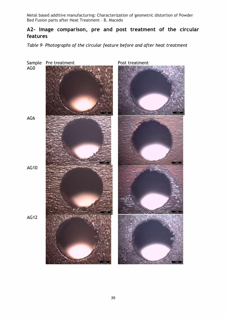
A2- Image comparison, pre and post treatment of the circular
features
Table 9– Photographs of the circular feature before and after heat treatment
Sample Pre treatment Post treatment AG0
AG6
AG10
AG12
Metal based additive manufacturing: Characterization of geometric distortion of Powder Bed Fusion parts after Heat Treatment – B. Macedo
40
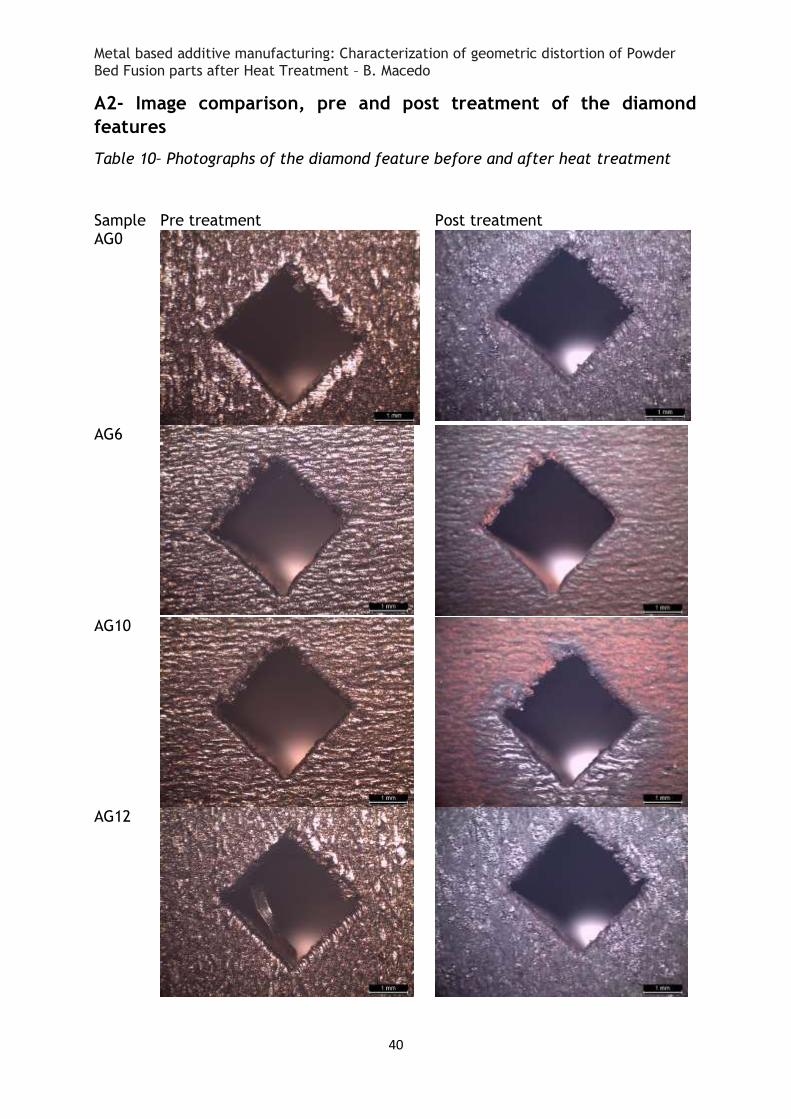
A2- Image comparison, pre and post treatment of the diamond
features
Table 10– Photographs of the diamond feature before and after heat treatment
Sample Pre treatment Post treatment AG0
AG6
AG10
AG12