Embed Size (px)
Citation preview

Modelação de Risco Operacional
Artur Miguel Ilhéu Viana de Queiroz
Dissertação para obtenção do Grau de Mestre em
Engenharia Informática e de Computadores
Júri
Presidente: Prof. José Manuel Nunes Salvador Tribolet
Orientador: Prof. Pedro Manuel Moreira Vaz Antunes de Sousa
Vogais: Prof. Artur Miguel Pereira Alves Caetano
Novembro 2009

Table of contents
ii | P a g e
TTaabbllee ooff ccoonntteennttss
Table of contents ................................................................................................................................. ii
Table of figures .................................................................................................................................... v
Table of tables .................................................................................................................................... vi
Acknowledgments ............................................................................................................................ viii
Resumo .............................................................................................................................................. ix
Palavras-Chave ................................................................................................................................... ix
Abstract ............................................................................................................................................... x
Keywords ............................................................................................................................................ x
Chapter 1 – Setting up an Approach..................................................................................................... 1
1.1 The Problem ......................................................................................................................... 1
1.2 Objectives ............................................................................................................................ 2
1.3 Audience and Scope ............................................................................................................. 2
1.4 Research Method ................................................................................................................. 3
1.5 Methodology........................................................................................................................ 4
1.6 Structure .............................................................................................................................. 5
1.7 Typographical Conventions .................................................................................................. 5
1.8 Abbreviations ....................................................................................................................... 6
Chapter 2 – State of the Art ................................................................................................................. 7
2.1 Defining Risk ........................................................................................................................ 7
2.2 Modelling ........................................................................................................................... 11
Chapter 3 – Identifying Risk Concepts ................................................................................................ 19
3.1 A Three-Way Approach ...................................................................................................... 19
3.2 Identifying the Concepts ..................................................................................................... 27
3.3 Concept and Methodology Overview.................................................................................. 30
Chapter 4 – Defining the Concepts ..................................................................................................... 31
4.1 The Three Basic Dimensions ............................................................................................... 31
4.2 Operational Risk Concepts .................................................................................................. 33

Table of contents
iii | P a g e
4.3 Business Process Concepts ................................................................................................. 40
4.4 Operational Risk-Oriented Business Process Meta-Model ................................................... 46
Chapter 5 – Modelling Operational Risk ............................................................................................. 48
5.1 Choosing a Language .......................................................................................................... 48
5.2 The Language Extension Meta-Process ............................................................................... 50
5.3 Applying the Meta-Process ................................................................................................. 51
5.4 Evaluating the Extensions ................................................................................................... 61
Chapter 6 – Validating an Approach ................................................................................................... 62
6.1 The Case Study ................................................................................................................... 62
6.2 The European Investment Fund .......................................................................................... 72
6.3 Overview ............................................................................................................................ 74
Chapter 7 – Formalizing Notational Extensions .................................................................................. 75
7.1 Data Object ........................................................................................................................ 75
7.2 Activity ............................................................................................................................... 76
7.3 Pool / Lane ......................................................................................................................... 79
7.4 Sequence Flow ................................................................................................................... 80
7.5 Message Flow..................................................................................................................... 80
7.6 Association ......................................................................................................................... 81
7.7 Other Extensions ................................................................................................................ 82
7.8 Final Notes ......................................................................................................................... 83
Chapter 8 – Evaluating an Approach .................................................................................................. 84
8.1 Contributions ..................................................................................................................... 84
8.2 Decisions and Misalignments ............................................................................................. 85
8.3 Limitations ......................................................................................................................... 87
8.4 Future Work ....................................................................................................................... 88
8.5 Conclusions ........................................................................................................................ 89
Bibliography ...................................................................................................................................... 91
Appendix A – BPMN Core Notation Elements..................................................................................... 93
Appendix B – eEPC Core Notation Elements ....................................................................................... 94
Appendix C – Muehlen’s BP taxonomy ............................................................................................... 95

Table of contents
iv | P a g e
Appendix D – Muehlen’s Risk taxonomy ............................................................................................ 96
Appendix E – KYE Meta-Model V7 ...................................................................................................... 97
Appendix F – The Operational Risk Business Process Meta-Model ..................................................... 98
Appendix G – The BPMN meta-model ................................................................................................ 99
Appendix H – The EPC meta-model .................................................................................................. 100
Appendix I – The BPMN Language Extension Meta-Process ............................................................. 101
Appendix J – The Risk Application interface ..................................................................................... 102
Appendix K – Muehlen’s example .................................................................................................... 103
Appendix L – The BPMN example without Risk ................................................................................ 104
Appendix M – The BPMN example with Risk .................................................................................... 105
Appendix N – Risk properties ........................................................................................................... 106
Appendix O – Risk reporting ............................................................................................................ 107
Appendix P – The BPMN example with Risk event testing ................................................................ 109
Appendix Q – The BPMN example with Risk control testing ............................................................. 110
Appendix R – The BPMN extensions Class Diagram .......................................................................... 111

Table of figures
v | P a g e
TTaabbllee ooff ff iigguurreess
Figure 1 – Research Method (Modelled in BPMN) ........................................................................ 3
Figure 2 – Working Methodology taken ........................................................................................ 4
Figure 3 – Risk Management Framework ..................................................................................... 8
Figure 4 – Risk Management Process .......................................................................................... 9
Figure 5 – The modelling concepts [17] ...................................................................................... 14
Figure 6 – Risk theories alignment with business process concepts ........................................... 19
Figure 7 – Cheng’s meta-model for operational risk modelling .................................................... 20
Figure 8 – Event /Resource implication graph ............................................................................ 21
Figure 9 – Colour mapping for business process related concepts ............................................. 28
Figure 10 – Operational Risk Meta-Model (adapted in UML Class Diagram) ............................... 34
Figure 11 – Business Process Meta-Model (adapted from [37]) .................................................. 41
Figure 12 – BPMN Risk Event Representation ........................................................................... 66
Figure 13 – Risk Events and Risk Controls inside Pool / Lanes .................................................. 67
Figure 14 – Risk Impact Calculations ......................................................................................... 69
Figure 15 – Event and Consequence Chain example ................................................................. 85
Figure 16 – Route Cause as Conditional BPMN Start Event example ......................................... 88
Figure 17 – Muehlen’s Business Process Taxonomy [32] ........................................................... 95
Figure 18 – Muehlen’s Risk Taxonomy [32] ................................................................................ 96
Figure 19 – KYE Meta-Model V7 (Link Consulting property) ....................................................... 97
Figure 20 – The Operational Risk-Oriented Business Process Meta-Model (adapted from KYE) . 98
Figure 21 – The BPMN Meta-Model (adapted from [38]) ............................................................ 99
Figure 22 – The EPC Meta-Model (adapted from [38]) ............................................................. 100
Figure 23 – The BPMN Language Extension Meta-Process ..................................................... 101
Figure 24 – Risk Application interface ...................................................................................... 102
Figure 25 – Muehlen's Payroll Process example in eEPC (see [24]) ......................................... 103
Figure 26 – Muehlen's Payroll Process example in BPMN (without risks) ................................. 104
Figure 27 – Muehlen's Payroll Process example in BPMN ........................................................ 105
Figure 28 – System Architect Risk Event, Control and Consequence property screenshots ...... 106
Figure 29 – Risk Event Report in System Architect................................................................... 108
Figure 30 – Highlight Event Chain macro applied on the case study ......................................... 109
Figure 31 – Activate Risk Control macro applied on the case study .......................................... 110
Figure 32 – Class Diagram of the notational extensions for [33] ............................................... 111

Table of tables
vi | P a g e
TTaabbllee ooff ttaabblleess
Table 1 – Chapter Structure ......................................................................................................... 5
Table 2 – Typographical Conventions .......................................................................................... 6
Table 3 – Abbreviations ............................................................................................................... 6
Table 4 – Relevant components of the Risk Management Framework .......................................... 9
Table 5 – Relevant components of the Risk Management Process ............................................. 10
Table 6 – Business process modelling language classification [20] ............................................. 15
Table 7 – Event / Resource implication matrix ............................................................................ 21
Table 8 – Resource / Task implication matrix ............................................................................. 21
Table 9 – Risk-related concepts ................................................................................................. 23
Table 10 – Risk type description ................................................................................................ 24
Table 11 – Error type description ............................................................................................... 24
Table 12 – Risk Management Strategies .................................................................................... 24
Table 13 – Risk models ............................................................................................................. 25
Table 14 – ISO/IEC 15504 VS i* concept mapping ..................................................................... 27
Table 15 – Literature Review concepts and keywords ................................................................ 28
Table 16 – Risk concepts mapping ............................................................................................ 29
Table 17 – Literature Review check matrix ................................................................................. 30
Table 18 – Adapted from Atkinson’s [36] semantic and syntactic approach ................................ 32
Table 19 – Risk Event syntax definition ...................................................................................... 36
Table 20 – Risk Consequence syntax definition ......................................................................... 38
Table 21 – Risk Control syntax definition .................................................................................... 40
Table 22 – Process syntax definition .......................................................................................... 43
Table 23 – Resource syntax definition ........................................................................................ 45
Table 24 – Goal syntax definition ............................................................................................... 46
Table 25 – Historic BPML Data .................................................................................................. 48
Table 26 – Language Comparative Evaluation ........................................................................... 49
Table 27 – The Language Extension Meta-Process methodology .............................................. 51
Table 28 – Strongest BPMN Reusable Candidates .................................................................... 52
Table 29 – Concept VS Candidate Affinity Mapping ................................................................... 54
Table 30 – Concept VS Candidate Validity Check ...................................................................... 54
Table 31 – BPMN Extensibility Restrictions ................................................................................ 56
Table 32 – Data Object Extensions ............................................................................................ 56
Table 33 – Goal Extensions ....................................................................................................... 57
Table of tables
vii | P a g e
Table 34 – Activity Extensions ................................................................................................... 57
Table 35 – Association and Message Flow Extensions ............................................................... 58
Table 36 – Activity Extensions ................................................................................................... 58
Table 37 – Resource VS Data Object Extensibility Validation ..................................................... 59
Table 38 – Goal VS New Concept Extensibility Validation .......................................................... 59
Table 39 – Risk Event VS Activity Extensibility Validation ........................................................... 59
Table 40 – Risk Consequence VS Activity Extensibility Validation .............................................. 60
Table 41 – Risk Control VS Activity Extensibility Validation ........................................................ 60
Table 42 – Final extensions semantic, syntactic and notational evaluation ................................. 60
Table 43 – Risk Application functionalities .................................................................................. 64
Table 44 – eEPC to BPMN risk transformations ......................................................................... 65
Table 45 – Risk Controls in the case study ................................................................................. 68
Table 46 – Comparative Modelling Evaluation ............................................................................ 70
Table 47 – Comparative Non-Modelling Evaluation .................................................................... 71
Table 48 – Data Object Extensions to Table 8.3 of [39] .............................................................. 75
Table 49 – Data Object extensions to Table 9.42 of [39] ............................................................. 76
Table 50 – Activity extensions to Table 8.3 of [39] ...................................................................... 76
Table 51 – Activity extensions to Table 9.25 of [39] .................................................................... 77
Table 52 – Activity extensions on new chapter 9.4.3.11 of [39] ................................................... 78
Table 53 – Activity extensions on new chapter 9.4.3.12 of [39] ................................................... 79
Table 54 – Pool / Lane extensions to Table 9.38 of [39] ............................................................. 80
Table 55 – Sequence Flow extensions to Table 8.4 of [39] ......................................................... 80
Table 56 – Message Flow extensions to Table 8.4 of [39] .......................................................... 80
Table 57 – Exclamation Mark versus Impact correspondence .................................................... 81
Table 58 – Message Flow extensions to Table 10.3 of [39] ......................................................... 81
Table 59 – Association extensions to Table 10.4.1 of [39] .......................................................... 81
Table 60 – Total Risk attribute extensions to Table 8.7 of [39] .................................................... 82
Table 61 – Risk Consequence definition extensions on new Chapter 8.7 of [39] ......................... 82
Table 62 – Goal definition extensions on new Chapter 8.8 of [39] ............................................... 83
Table 63 – BPMN core notation element set (adapted from [39]) ................................................ 93
Table 64 – eEPC notation elements (adapted from [26]) ............................................................ 94
Table 65 – Risk Event Reporting .............................................................................................. 107
Table 66 – Risk Consequence Reporting ................................................................................. 108
Table 67 – Risk Control Reporting ........................................................................................... 108

Acknowledgments
viii | P a g e
AAcckknnoowwlleeddggmmeennttss
Àqueles que nunca desistem…

Resumo
ix | P a g e
RReessuummoo
Devido ao seu impacto disruptivo, as organizações já não estão deslocadas da realidade do
Risco. Contudo, tais preocupações já não se cingem ao seu impacto económico ou às suas finanças; o
risco subjacente às operações, o Risco Operacional, ganhou muito protagonismo recentemente. Com ele
cresceu também a necessidade de traduzir as suas particularidades em modelos de risco operacional.
Este trabalho cobre a problemática conjunta do Risco Operacional e da Modelação no contexto dos
processos de negócio. Primeiramente identificando as principais correntes relacionadas com risco, as
suas sinergias e os principais conceitos envolvidos. Em segundo lugar, usando o meta-modelo unificado
KYE como base de trabalho para a definição sintáctica e semântica dos conceitos. Depois disso
utilizando o Meta-Processo de Extensão de Linguagem no BPMN, de forma a identificar conceitos
reutilizáveis e extensíveis, e culminando num conjunto de extensões notacionais. De seguida modelando
e testando a abordagem num caso de estudo e através de uma reunião de validação com o Fundo de
Investimento Europeu. Finalmente formalizando as extensões no formato de especificação do BPMN.
PPaallaavvrraass--CChhaavvee
Risco
Risco Operacional
Modelação
Linguagens de Modelação de Processos de Negócio
BPMN
Modelação de Risco Operacional
Extensões Notacionais

Abstract
x | P a g e
AAbbssttrraacctt
Aggravated by its disruptive impact, Risk is no longer detached from nowadays organizational
concern. However such preoccupation is no longer restricted to its impact on finance and economics; the
risk underpinning the operations, the Operational Risk, has gained major interest in recent times. Along
with it arose a growing need to translate its idiosyncrasies onto visual operational risk models. This work
addresses the joint problematic of Operational Risk and Modelling in a business process context. First of
all, the mainstream risk-oriented currents, their synergies, and the core concepts involved are elicited.
Secondly, the unified KYE meta-model is used as a working basis for the definition of the semantics and
syntax of the concepts. After that a Language Extension Meta-Process is used on BPMN, and tested for
reusable and extensible concepts, culminating in a group of notational extensions. Then the entire
approach is modelled and tested in a case study and via a European Investment Fund validation meeting.
Finally the proposed extensions are formalized using BPMN’s specification format.
KKeeyywwoorrddss
Risk
Operational Risk
Modelling
Business Process Modelling Languages
BPMN
Operational Risk Modelling
Notational Extensions

Chapter 1 – Setting up an Approach
1 | P a g e
CChhaapptteerr 11 –– SSeett tt iinngg uupp aann AApppprrooaacchh
Risk-related issues have been a major concern in many society fields, like finance, economy,
psychology, civil protection or politics. This has become more critical in the last decades, and an
unquestionable proof of that is the rising of multiple insurance companies, with auto, credit, health or
other personal and organizational solutions for the unpredictability of the occurrence of harmful events.
With the growing interest in enterprise disciplines such as organizational engineering or business
process management, and with the change in the working paradigm towards business processes, a new
word has born in the risk context. Operational Risk is the new risk term, focusing more on risks present on
how things are done inside an organization, and finding out vulnerabilities in the enterprise artefacts due
to the occurrence of an unwanted event. Even though the growing maturity on the business process field,
there still is a great margin of progress in the operational risk area. Only recently with The Basel II Accord
it became a real protagonist, with some formalization and standardization insights.
In the organizational engineering area remarkable achievements have been made; the Enterprise
Architecture has brought the organization to a completely new level. The idea of creating formal
enterprise blueprints concerning different stakeholder perspectives gave it an outstanding analysis,
traceability and descriptive tool. Concordantly, in order to provide standard methods for describing the
organization realities, business stakeholders started to rely on formal modelling techniques. Modelling, as
an abstractive tool, gave business modellers the capacity to translate real-world realities into structured
diagrams that obeyed to formal syntactic, notational and semantic rules. Business Process Modelling
Languages were developed to handle with business process specific concerns.
However the task of merging these two realities has not been so harmonizing. The lack of a true
formal risk concept definition and the difficulty for creating models that map risk-related issues, are two
examples of that. This work is positioned at this standstill point, where the lack of meta-modelling
definitions and the modelling suitability of the existing languages are either underdeveloped or unknown.
1.1 The Problem
The background defined in the previous section highlighted one crucial issue, henceforth called as
the problem which this thesis is trying to overcome: How to Model Operational Risk in a business
process context. This problem arises from the merger of two areas that so far have been disconnected:
• Operational Risk – its underpinning concepts have been scattered across multiple theories,
with different meanings and lacking a unified vision that joins them in a standard meta-model;

Chapter 1 – Setting up an Approach
2 | P a g e
• Modelling – there are numerous modelling languages, with heterogeneous levels of maturity
and formality and covering a wide range of areas such as business process modelling, plus
there is no dedicated approach for operational risk modelling.
The combination of these areas has so far suffered a lack of study in the community literature
review, with very few research papers trying to develop modelling approaches for operational risk.
1.2 Objectives
The identified problem highlighted the need of tracing the bisector between the operational risk
and modelling areas; thus, Enable Operational Risk Modelling, in a business process context, is the main
objective of this thesis, and it can be decomposed in a set of sub-objectives leading to its main purpose:
1. Identify the constraints and synergies between the operational risk and modelling areas;
2. Identify and define the set of operational risk related concepts;
3. Test and contrast these concepts against the modelling capabilities of a chosen mainstream
modelling language;
4. Develop an operational risk modelling approach in the chosen business process modelling
language based on the capability results of the previous stage;
5. Validate the approach in a real-world context.
These sub-objectives establish a working roadmap for the thesis contents. They must be issued
sequentially, and by accomplishing each individual objective the works leans towards the achievement of
its ultimate goal.
1.3 Audience and Scope
This work is addressed to a significantly restricted audience, since its concepts and contents are
mainly focused to those capable of dealing with modelling and risk techniques in business process
contexts. Thereby its major stakeholder would be the Risk Analyst, an individual capable of
understanding their joint idiosyncrasies, such as the risk impact of a determined event in an
organization’s business process, as well as its propagation, consequences and how to counter it through
preventive measures. This does not discard other stakeholders; managers can still use this along their
enterprise architecture knowledge in order to corroborate architectural modifications, since severe risks
may justify so; modellers may complement their modelling knowledge with this approach, creating a
universal communication tool to assess and evaluate the processes; finally software designers may refer
to this work in order to address process enactment, by creating BPEL mappings and macros, they create
the background for the execution of business processes.
The scope of this work is restricted to the following issues:

Chapter 1 – Setting up an Approach
3 | P a g e
• Creating syntax, semantic and notational definitions for the identified concepts (business
process and operational risk) present in a chosen meta-model;
• Establishing formal methods for identifying reusable concepts on the chosen business process
modelling language in order to develop an operational risk modelling approach;
• Establishing formal methods for extending the concepts of the chosen business process
modelling language if misalignments between them and the defined concepts are found;
• Developing a method for representing risk using the reused (or extended) concepts;
• Formally defining the notational extensions on the language specification format if needed.
Out of the scope of this work remain:
• Developing an optimal meta-model for representing risk using the state of the art approaches;
• Testing multiple languages on the meta-model in order to find the best modelling approach;
• Creating a language extension universal method;
• Creating automation mechanism for any of the developed notational extensions.
1.4 Research Method
The research method that was applied for the development of this master thesis can be
represented as a set of interlinked activities, with inputs and outputs, just as BPMN Business Process
(see the next chapter). The activities that compose the research process can be divided into five groups
with a series of intermediary artefacts, as described below.
Figure 1 – Research Method (Modelled in BPMN)
• Contextualization – These were the early stages of the thesis development where the
objectives, scope, approach and deadlines were established by the master’s coordinator;
MastersStudent
MastersCoordinator
Establish FormalRequirements
ThesisRequirements
Thesis FinalDocument
Submit FinalVersion
DocumentSelection
Key-PointHighlighting
Review?
DefineApproach
SetObjectives
DraftRevision
DraftingContextAnalysis
ReadingDocumentCataloging
DocumentFiltering
ThematicResearch
ThesisDraft
Key-Points
Contextualization
Content ProductionInformation Gathering Document Analysis
Revision
Yes No
Chapter 1 – Setting up an Approach
4 | P a g e
• Information Gathering – Having the previous as an input, the Information Gathering activities
reflect the literature review stage. A series of scientific articles, technical books, older thesis
and other unclassifiable documents were selected for reading, according to their relevance;
• Document Analysis – The Reading and Key-Point Highlighting activities summarize the
method that was applied for each document whose content was selected as relevant for the
thesis. A list of the key-issues of each document was the output of this stage;
• Content Production 1 – This group encompasses the core activities of the thesis. First, by
reviewing the key-points highlighted before, and contextualizing them in the thesis structure.
Then by the production of text per se, including, new content, citations2, tables, figures, etc;
• Revision – The communication with the master thesis coordinator was made during
brainstorming meetings, where the draft versions of the thesis were validated and reviewed for
further improvement, till a final master thesis document was produced.
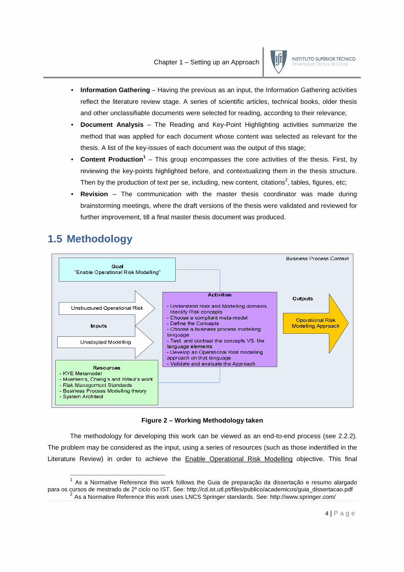
1.5 Methodology
Figure 2 – Working Methodology taken
The methodology for developing this work can be viewed as an end-to-end process (see 2.2.2).
The problem may be considered as the input, using a series of resources (such as those indentified in the
Literature Review) in order to achieve the Enable Operational Risk Modelling objective. This final
1 As a Normative Reference this work follows the Guia de preparação da dissertação e resumo alargado
para os cursos de mestrado de 2º ciclo no IST. See: http://cd.ist.utl.pt/files/publico/academicos/guia_dissertacao.pdf 2 As a Normative Reference this work uses LNCS Springer standards. See: http://www.springer.com/

Chapter 1 – Setting up an Approach
5 | P a g e
outcome has only been achieved because a series of sequential and complementary activities were taken
in order to produce an innovative approach as the principal result.
1.6 Structure
This thesis is divided into eight chapters, each of them subdivided into multiple subsections
according to their content. Each chapter addresses one or more of the sub-objectives established in the
Objectives section, and can be viewed as the activities described in the Methodology.
Chapter Description
1 This chapter establishes the main issues that are going to be discussed in this thesis, as
well as the structure of the document and the way the contents are disposed.
2 In this chapter an extensive literature review on the modelling and operational risk areas is
made. Their roots and current main issues are studied, and their synergies identified.
3
This chapter provides a widespread insight on some of the most relevant operational risk
visions. These are used as a working basis for the identification of the core elements that
should be part of the Operational Risk-Oriented Business Process Meta-Model.
4 This chapter shows how the identified elements are unified under KYE meta-model, and
adds an extensive definition of its concepts under syntactic and semantic parameters.
5
In this chapter a testing methodology is developed for applying on the chosen Business
Process Modelling Language - BPMN. As part of the method, a group of reusable concepts
is analyzed and a set of notational extensions proposed under BPMN extensibility rules.
6 In this chapter the notational extensions are validated under their high-level and low-level
properties. A case study and the European Investment Fund validation are introduced.
7 This chapter formalizes the validated extensions under BPMN’s specification format.
8 This evaluates the whole approach in its contributions, decisions, limitations and future work.
Table 1 – Chapter Structure
1.7 Typographical Conventions
The type styles shown below are used in this document to distinguish its different contents.
Body Text Arial – 10 pt with 1,5 line spacing.
Headings
Heading 1:
Arial – 16 pt.
Bold
Heading 2:
Arial – 14 pt.
Bold
Heading 3:
Arial – 14 pt.
Bold
Heading 4:
Arial – 12 pt.
Bold
Heading 5:
Arial – 10 pt.
Bold
Captions Arial – 10 pt. Bold

Chapter 1 – Setting up an Approach
6 | P a g e
Concepts The first appearance of a concept in the text is made in Italic, bold and with
the first letter capitalized. The remaining are in plain text.
Quotes “Citations are inserted between quotes, in italic, with single line spacing”.
Important ideas The most relevant ideas from a written text are in bold .
Abbreviations They are written in CAPITAL letters.
Foreign words / Variables
/ Expressions / Names / They are written in italic. They may be underlined if they are very important.
Figures / Tables /
Checkpoints These may not obey any typographical convention.
Table 2 – Typographical Conventions
1.8 Abbreviations
BPD Business Process Diagram
BPEL Business Process Execution Language
BPEL4WS Business Process Execution Language for Web Services
BPM Business Process Management
BPMI Business Process Management Initiative
BPML Business Process Modelling Language
BPMN Business Process Modelling Notation
CEO Centro de Engenharia Organizacional
eEPC extended Event-driven Process Chains
EIF European Investment Fund
EPC Event-Driven Process Chain
EPML Event-Driven Process Chain Markup Language
GORE Goal-Oriented Requirements Engineering
IDEF Integrated Definition
IEC International Electrotechnical Commission
ISO International Organization for Standardization
KYE Know Your Enterprise
MAR Modelo de Avaliação de Riscos
OMG Object Management Group
PAM Process Assessment Model
UML Unified Modelling Language
XML Extensible Markup Language
Table 3 – Abbreviations
Chapter 2 – State of the Art
7 | P a g e
CChhaapptteerr 22 –– SSttaattee ooff tthhee AArrtt
In order to enable operational risk modelling it is first necessary to understand what these two
areas are. This chapter covers a vast number of concepts making an extensive literature review on both
areas in order to identify their roots, understand their main concerns, and comprehend in which way they
are related with each other, either in a synergistic or in a contrasting way.
2.1 Defining Risk
“1. Expose to a chance of loss or damage; 2. A source of danger; a possibility of incurring loss or misfortune; 3. A venture undertaken without regard to possible loss or injury; 4. Take a risk in the hope of a favourable outcome; 5. The probability of being exposed to an infectious agent”.3
The widespread use of the term Risk does not necessarily imply the existence of a definition for it.
Glyn Holton [1] strives in an attempt to define risk based on the assumption that it entails two
basic components: Uncertainty and Exposure. Uncertainty is considered to be the state of not knowing
whether a proposition is true or false, or being oblivious about it. Probabilities are often used to quantify
the perceived uncertainty. Exposure is described as the self-consciousness of a preposition in terms of
having a personal opinion or preference about it, and taking the consequences of it. Given these
premises, Holt defines risk in wide context, such as business, military issues or sports: He states:
“The situations may appear disparate, but they share certain common elements. First, people care about outcomes. If someone has a personal interest in what transpires, that person is exposed. Second, people don’t know what will happen. In each situation, the outcome is uncertain.
(…) Risk, then, is exposure to a proposition of which i s uncertain .”
Due to this self-aware circumstance, Holt defends that organizations, companies and
governments are not at risk; risk is a condition of individuals, so companies are merely a conduit through
which they take risk. This fact is rarely acknowledged in today’s literature, which tend to treat companies
as risk takers. This vision derives from fact that risk encompasses a wide range of areas, such as:
3 Retrieved at 03/01/2009 from: http://www.lookwayup.com/
Objectives to Achieve
2. Identify the constraints and synergies between the Operational Risk and Modelling areas.
a. Overview risk-related issues
b. Overview modelling-related issues

Chapter 2 – State of the Art
8 | P a g e
• Political;
• Regulatory;
• Market;
• Professional;
• Economic;
• Socio-Cultural;
• Health & Safety;
• Technological;
• Contractual;
• Environmental;
• Physical;
• Operational.
One of the biggest steps to standardization was made in the context of the Basel II Accord4, in an
effort to create an international standard that banking regulators could use when creating regulations
about how much capital banks needed to put aside, to guard against the types of financial and
operational risks banks faced. Basel II covers important financial-oriented risk types, especially credit,
market and operational risk; however, more detail will be given in the following sections.
2.1.1 Risk Management
Risk Management is a discipline that has recently emerged to address the issues evolving risk. It
is the process by which an organization reaches decisions, to adequately control the risks which it
generates, or to which it is exposed. It is a structured approach to manage uncertainty related to a threat.
The International Standards Organization developed in the ISO31000 [2] a risk management
framework, eleven fundamental principles and a set of necessary activities, the so-called Process for
Managing Risk , for accomplishing the risk management effort. Although the practice of risk management
has developed over time and within diverse sectors, this generic approach consisting of a framework of
essential elements can help to ensure that risk is managed effectively and coherently across an
organization. The eleven principles of this framework described in [2] are directly interconnected with the
five-step risk managing components:
Figure 3 – Risk Management Framework
4 Retrieved at 27/11/2008 from: http://en.wikipedia.org/wiki/Basel_II
Chapter 2 – State of the Art
9 | P a g e
The greatest merit of this approach is the fact of being orthogonal to the different risk areas. Each
step is crucial to an effective risk management plan, but only the most relevant will be highlighted:
Component Description
Design of framework
for managing risk
• understand the organization’s internal and external context;
• establish a risk management policy ;
• integrate risk management within organizations practises and processes;
• provide accountability and authority for managing risks;
• provide the appropriate resources for risk management;
• establish internal / external communication and reporting mechanisms.
Implementing risk
management
This is where both, the framework and the process are effectively created. To
implement the framework the timings and strategies must be defined, risk
management policy applied, information and training sessions held and
constant communication with stakeholders must be realized.
Table 4 – Relevant components of the Risk Managemen t Framework
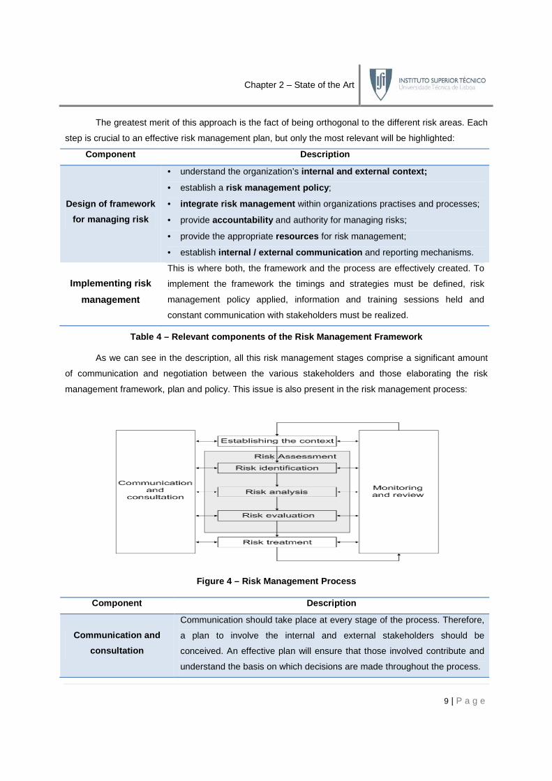
As we can see in the description, all this risk management stages comprise a significant amount
of communication and negotiation between the various stakeholders and those elaborating the risk
management framework, plan and policy. This issue is also present in the risk management process:
Figure 4 – Risk Management Process
Component Description
Communication and
consultation
Communication should take place at every stage of the process. Therefore,
a plan to involve the internal and external stakeholders should be
conceived. An effective plan will ensure that those involved contribute and
understand the basis on which decisions are made throughout the process.

Chapter 2 – State of the Art
10 | P a g e
Recording the risk
management process
Risk management activities should be traceable. Records provide the
foundation for improvement in methods, tools as well as the overall process.
Monitoring and review
• analyzing and learning lessons from events, changes and trends;
• detecting changes in the external and internal context including to the
risk itself which may require revision of risk treatments and priorities;
• ensuring that the risk control and treatment measures are effective;
Table 5 – Relevant components of the Risk Managemen t Process
From the analysis of the entire ISO 31000 Risk Management guidelines [2] it is possible to
highlight a series of underpinning issues. Firstly the constant need of communication . Secondly, how it
emphasizes the importance of stakeholders in the process of managi ng risk and how their needs
must be addressed to ensure the success of the whole approach. Lastly, how at various stages there is
the necessity to document, record and trace back inform ation produced before .
2.1.2 The Basel II Accord
The Basel Accords were born as an effort to harmonize banking supervision, regulation, and
capital adequacy standards across the eleven countries of the Basel Group5 and many other emerging
market economies. The Basel II Accord [3][4] emerged as an improvement of the original document,
expanding the scope, technicality, and depth of the original accord, to cover new approaches to credit
risk, adapt to the securitization of bank assets, cover market, operational, and interest rate risk, and
incorporate market-base surveillance and regulation. The Basel II Accord is supported by three pillars:
I. The first pillar deals with maintenance of regulatory capital calculated for three major
components of risk that a bank faces: Credit Risk , Operational Risk and Market Risk ;
II. The second pillar deals with the regulatory response to the first pillar. It provides a framework
for dealing with all the other risks a bank may face, such as systemic risk, concentration
risk, strategic risk, reputation risk, liquidity risk or legal risk, which the accord combines under
the title of Residual Risk . It gives bank a power to review their risk management system;
III. The third pillar looks to increase market discipline within a country’s banking sector, by
augmenting the disclosures that a bank must make to the general public.
Although being a strongly financial-oriented approach, The Basel II Accord provides some strong
suggestions and insights in what will so forth be called Operational Risk [5], and defines it as:
“Operational risk is defined as the risk of loss resulting from inadequate or failed internal processes, people and systems or from external events. This definition includes legal risk, but excludes strategic and reputational risk.” [4]
5 Retrieved at 04/12/2008 from: http://en.wikipedia.org/wiki/Basel_Commitee_on_Banking_Supervision
Chapter 2 – State of the Art
11 | P a g e
Nevertheless, the Basel II Accord has a series of flaws in a variety of issues. First of all the notion
of operational risk is quite vague, lacking a true depiction of what process, people or system risks are.
Besides that, this framework assumes that the organization knows how to calculate its operational risk,
but none is said in what factors generate such risk, how to measure their impact or how to evaluate their
relative importance. In addition to that, there is no explanation in how operational risk is structured, how to
formalize it, how to represent it and how to transmit its information to other stakeholders. Even though the
accord’s incompleteness towards a series of issues being quite alarming, it is probably the most
significant standardized approach to the risk problematic.
2.2 Modelling
The origins of the word Modelling are as old as we can probably think, assuming an incredible
variety of forms. Good examples are the early writing systems, such as proto-writing, using ideographic or
early mnemonic symbols to convey information, even though devoid of direct linguistic content. Many
other examples could be identified as modelling, such as the blueprints of an engineering system, the
architectural plans for a building or the chemical chain of a certain drug. The question is: Why do we use
models? According to Jon Holt [6] the answer is because a model is a simplification of reality that:
• increases our understanding;
• identifies areas of complexity;
• eases communication.
In the context of understanding the boundaries inherent to modelling, Holt also identified a series
of basic requirements that should be present in many kinds of models:
Checkpoint
With the introduction and analysis of Risk and Risk Management concepts, some important
issues aroused. Firstly the inexistence of a formal risk definition and risk hierarchy for the
creation of a standard in the area. Then, in how the risk as whole is dealt by organizations, with
the ISO 31000 approach. Finally, in how the Basel II Accord tried to define pillars to structure
the area. This analysis uncovered one central question, and some complementary issues.
How should risk information be captured and transmi tted to the stakeholders?
Objectives Completeness
a. Overview risk-related issues √
Chapter 2 – State of the Art
12 | P a g e
• the choice of model – the ability to choose the right approach can be very cost saving;
• the abstraction of the model – the capability of providing different levels of granularity for a
certain model, depending on the abstraction or detail, can be extremely helpful;
• the connection to reality – the aptitude to translate exactly the precise amount of information
onto a model, without missing relevant information or overloading it with unnecessary one;
• different views – the capacity of creating different and consistent perspectives of the same
model to different stakeholders, by filtering the information that is useful for each one.
It is not necessary to go further to understand the importance of modelling as a solution for some
of the problematic questions elected in the previous section. In the scope of this work we can understand
the importance of modelling, as a facilitator to address the difficulties related to risk identified in the
previous section. But before analysing in which ways modelling supports risk, and more importantly,
operational risk, it is important to understand what premises must be attained to comply with such task.
The definition of operational risk is mentioned as the loss resulting from failed internal processes ,
people and systems . That means that the modelling techniques to be found must encompass these
notions. Concordantly in the next sections the Enterprise Architecture and Business Process Modelling
disciplines are studied, as they support modelling techniques which cover those notions.
2.2.1 Enterprise Architecture Modelling
The Enterprise Architecture (see [7] and [8]) is a concept that has been around for almost
twenty years, albeit the numerous definitions for this term, such as:
“Enterprise architecture consists of defining and understanding the different elements that make up the enterprise and how those elements are inter-related.” [9]
“Enterprise architecture is the set of representations required to describe a system or
enterprise regarding its construction, maintenance and evolution” [10]
Moreover, depending on the concepts considered relevant to be addressed inside an
organization, there is a considerable variety of frameworks for structuring them in a coherent way.
The relevance of introducing this concept is to understand that the way in which these enterprise
concepts are defined and connected is extremely relevant for accomplishing the premises needed for
modelling and understanding operational risk. This means that the organization must be correctly mapped
and modelled, independently of the enterprise architecture framework chosen. Understanding in which
way processes, systems and people fit in the enterprise architecture is largely dependent on the
modelling language that is chosen to accomplish such task.
The next section clarifies how business process modelling, the business-oriented solution for
modelling an enterprise architecture, arose as the bridging concept for modelling and operational risk.
Chapter 2 – State of the Art
13 | P a g e
2.2.2 Business Process Modelling
The concept of Business Process Modelling has risen in the context of Business Process
Management (BPM) [11], which deals with the efficient coordination of business activities within
companies, with roots in the economic theory of Jules Henri Fayol6 and mass production of Henry Ford7.
Since then the concept has evolved, and nowadays is a field of management focused on aligning
organizations with the wants and needs of clients, throughout a holistic vision of the organization, in which
the main concept is the Business Process. By this order, Beckler [12] and Davenport [13] define it as:
“A process is a completely closed, timely and logical sequence of activities which are required to work on a process-oriented business object. (...) A business process is a special process that is directed by the business objectives of a company and by the business environment. Essential features of a business process are interfaces to the business partners of the company.”
“A [business] process is thus a specific ordering of work activities across time and place,
with a beginning, an end, and clearly identified inputs and outputs: a structure for action.”
Based on this business process management could be defined as the set of all management
activities related to business processes. These concepts are meaningful in this context, as they provide
the background for the emergence of business process modelling. Jon Holt [6] defines it as:
“ Business Process Modelling: any process modelling exercise that is performed in order to enhance the overall operation of a business.”
Its importance is justified due to the business-oriented nature of the enterprise architecture, where
the business process plays a central role, and so do the languages that model it. However another
problem arises, since the number of languages is vast and their scope and applicability is not the same.
6 Retrieved at 11/12/2008 from: http://en.wikipedia.org/wiki/Jules_Henri_Fayol 7 Retrieved at 11/12/2008 from: http://en.wikipedia.org/wiki/Henry_Ford
Checkpoint
Modelling is a structured answer for creating simplified visual representation of complex realities.
Its capabilities have been used to represent organizations through Enterprise Architectures.
Business Process Modelling is the practical answer for addressing the business shift towards
Business Processes. All these concepts try to respond to the necessity of defining the constructs
of an organization, structuring its elements, understanding their interactions and creating tools
for the stakeholder’s support. The hardest part is to understand how Risk will be addressed in
these models, with focus on processes, people and systems.

Chapter 2 – State of the Art
14 | P a g e
2.2.3 Business Process Modelling Languages
The drill down made so far led to a particular subgroup of languages, the Business Process
Modelling Languages (BPML) [14][15], as the ones that will be object of study. However, since the
diversity spectre of languages still is so vast, it is import to make a more accurate refinement.
2.2.3.1 Modelling Taxonomies
Both Caetano [17] and Wand [16] provide an excellent working basis for defining and
distinguishing the universe of modelling concepts found in the mainstream literature, which will be used
for the definition of the basic concepts of the chosen language:
Figure 5 – The modelling concepts [17]
• Semantics – bind the constructs defined in the syntax to a meaning. This can be done in a
mathematical way (such as by using a formal ontology or operational semantics);
• Syntax – provides a set of constructs and a set of rules for how they can be combined;
• Notation – defines a set of graphical symbols that are utilized for the visualization of models;
• Modelling Tool – provides the practical application of a modelling technique;
• Method – defines procedures by which a modelling language can be used. The result of
applying the modelling method is a model that complies with a specific modelling language.
2.2.3.2 Definitions
Caetano [17] defines Business Process Modelling Languages as:
“Business process modelling languages guide the procedure of business process modelling by offering a predefined set of elements and relationships for the modelling of business processes. A business process modelling language can be specified using a meta-model. In conjunction with a respective method, it establishes a business process modelling technique.”
It is important to distinguish what is commonly known as a generic Meta-Model from a Business
Process Meta-Model . An example of generic meta-model is an Enterprise Architecture, providing the
basic constructs for defining the different architectures of an organization. Examples of this are the
Framework CEO [18] or the ARIS Meta-Model [19]. The Business Process Meta-Model, is a subset
extracted from the first, highlighting the business constructs. Holt [6] defines it as:
Chapter 2 – State of the Art
15 | P a g e
“A meta-model is, quite simply, a model of a model. Therefore, the process meta-model is a model of a model that is used for process modelling.”
Due to the vast offer in meta-modelling approaches the number of modelling languages is also
large. This happens because the expressive power (syntax and semantics) of each language is
sometimes limited and focused on specific areas, leaving gaps that can only be overcome through
extensions to the language, or using a different one.
2.2.3.3 Carlsen Classification
Given the large number of languages, there have been several attempts in order to classify and
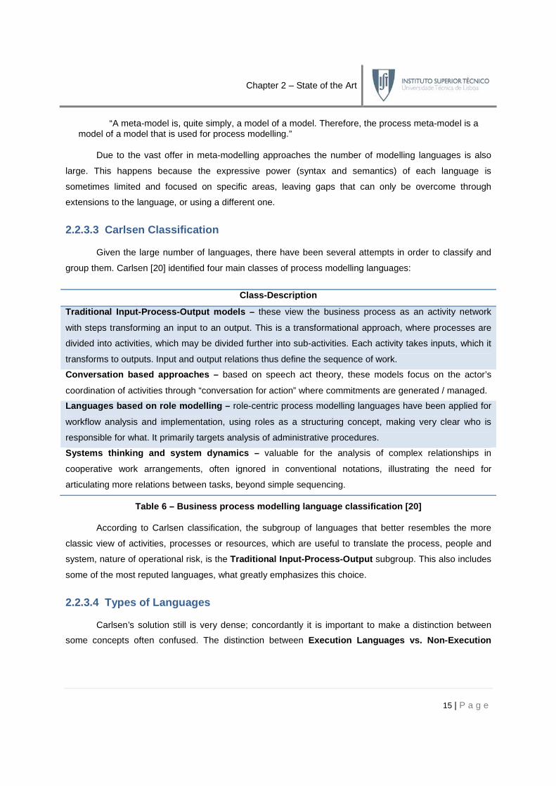
group them. Carlsen [20] identified four main classes of process modelling languages:
Class -Description
Traditional Input -Process -Output models – these view the business process as an activity network
with steps transforming an input to an output. This is a transformational approach, where processes are
divided into activities, which may be divided further into sub-activities. Each activity takes inputs, which it
transforms to outputs. Input and output relations thus define the sequence of work.
Conversation based approaches – based on speech act theory, these models focus on the actor’s
coordination of activities through “conversation for action” where commitments are generated / managed.
Languages based on role modelling – role-centric process modelling languages have been applied for
workflow analysis and implementation, using roles as a structuring concept, making very clear who is
responsible for what. It primarily targets analysis of administrative procedures.
Systems thinking and system dynamics – valuable for the analysis of complex relationships in
cooperative work arrangements, often ignored in conventional notations, illustrating the need for
articulating more relations between tasks, beyond simple sequencing.
Table 6 – Business process modelling language class ification [20]
According to Carlsen classification, the subgroup of languages that better resembles the more
classic view of activities, processes or resources, which are useful to translate the process, people and
system, nature of operational risk, is the Traditional Input-Process-Output subgroup. This also includes
some of the most reputed languages, what greatly emphasizes this choice.
2.2.3.4 Types of Languages
Carlsen’s solution still is very dense; concordantly it is important to make a distinction between
some concepts often confused. The distinction between Execution Languages vs. Non-Execution

Chapter 2 – State of the Art
16 | P a g e
Languages and Graphical Languages vs. Non-Graphical Languages is crucial to understand the
choice of the language. The BPMN Forum8 makes an important contribution, to distinguish both groups:
“These differences refer to variations in the semantics of the business modelling languages. Executable Business Modelling Languages are associated with precise semantics that can be used to automatically validate and simulate business processes (e.g., BPEL) whereas non-executable business modelling languages lack precise semantics (e.g., BPMN).”
“These differences refer to variations in the concrete syntax of the business modelling
languages. Graphic business modelling language s typically use a visual notation of 2D symbols (e.g., the "boxes and lines" used in BPMN and UML), whereas non-graphic business modelling languages use a text-based notation (e.g., BPEL, which is defined with XML notation).”
Execution Languages are textual descriptions of business processes, built towards their
enactment and automation. On the other hand, traditional Modelling Languages have a graphical
notation associated; this enables the stakeholders to sketch and model their business processes in a
visual comprehensible way. Some languages can be mapped onto an execution language, allowing both,
the design and the execution of a business process. The Non-Execution Languages group is the
chosen one since their syntactic and semantic definitions are not necessarily intentioned to be executed,
thus having a less formal rigidity and more flexibility for the purpose of possible extensions.
The focus of this work is centred in the Graphical Languages , as they provide a better
communication tool and will better serve the purpose of analysing operational risk modelling capabilities.
2.2.3.5 Mainstream Languages
The refinement made so far has driven the language selection to a quite smaller group, of which
one is to be chosen. Obeying the classification criteria referred before, four mainstream modelling
languages have been identified, and all reputed in the academic and enterprise fields: BPMN, UML, EPC
and IDEF. Apart from the classification, it is hard to appoint formal criteria to decide whether a language
should or not be included. The literature review did not provide any valid answers in terms of selection
criteria in this area. Since four languages still is a vast number the task of selecting a specific language is
addressed on later chapters, when a deeper insight on this issue is made.
2.2.3.6 BPMN
The Business Process Modelling Notation 9 is a widespread business modelling language, with
large acceptance in the enterprise world. BPMN was developed by the Business Process Management
Initiative (BPMI), and is currently maintained by the Object Management Group (OMG) since the two
8 Retrieved at 19/12/2008 from: http://www.bpmnforum.com/FAQ.htm 9 Retrieved at 28/12/2008 from: http://en.wikipedia.org/wiki/BPMN

Chapter 2 – State of the Art
17 | P a g e
organizations merged in 2005. The current version is 1.1, and a major revision process for 2.0 is in
progress. It was developed with two main objectives in mind, present in the specification document [21]:
“The primary goal of BPMN is to provide a notation that is readily understandabl e by all business users (...) Thus, BPMN creates a standardized bridge for the gap between the business process design and process implementation.”
“Another goal, but no less important, is to ensure that XML languages designed for the
execution of business processes , such as BPEL4WS (Business Process Execution Language for Web Services), can be visualized with a business-oriented notation.”
Bearing this in mind, they defined the notation and semantics of Business Process Diagram
(BPD), representing the amalgamation of best practices within the business modelling community. Other
important aspect of BPMN is its scope. BPMN was developed to support only the concepts that are
applicable to business processes . Modelling the organizational structures and resources, functional
breakdowns or data and information is not a supported feature. Finally, in terms of extensibility, it was
designed to cope with the addition of non-standard elements added by modellers or modelling tools.
This should be done under firm restrictions, to avoid the loss of comprehensibility of the notation’s
semantics and syntax. Refer to Appendix A for the notation and Appendix G for the meta-model.
2.2.3.7 UML
Born in 1997, the Unified Modelling Notation [22] is a graphical language for visualizing,
specifying, constructing, and documenting the artefacts of a software-intensive system. The current
version is UML 2.0; the UML Specification was split into two complimentary specifications:
Infrastructure [23] and Superstructure [24]. The first defines the foundational language constructs the
second defines the user level constructs. The two constitute a complete specification.
Despite of its software-oriented nature it has been used for a wide range of modelling domains;
there are 13 types of diagrams divided into three categories [22]: Behaviour diagrams , which describe
the overall functionality of the software at a high-level of abstraction. Interaction diagrams , which
describe the system functionality in terms of object interactions. And Structure diagrams, capturing the
static structure of a software system. Although not providing a specific diagram for business process
modelling, some diagrams have been combined, adapted and extended for this purpose, such as UML
2.0 Activity Diagrams , mostly used for their resemblance for the business process definition.
2.2.3.8 IDEF
The Integrated DEFinition 10 methods are a family of modelling languages in the field of software
engineering. They cover a range of uses from function modelling to information, simulation, object-
10 Retrieved at 29/12/2008 from: http://en.wikipedia.org/wiki/IDEF

Chapter 2 – State of the Art
18 | P a g e
oriented analysis and design and knowledge acquisition. They were developed under the funding of the
United States Air Force, and became well established standard modelling techniques.
The IDEF3 Process Description Capture Method [25] was created specifically to capture
descriptions of sequences of activities. It provides a structured method for achieving knowledge
acquisition, by capturing assertions about real-world processes and events. This way of expressing the
knowledge of an organization, through descriptions and beliefs, can be done from multiple viewpoints.
IDEF3 knowledge acquisition methods are structured through Scenarios , responsible for binding the
context of an IDEF3 Process Description 11.
2.2.3.9 EPC
The Event-driven Process Chains [26] [27], have become a widespread process modelling
technique, because of the success of products such as SAP R/312 and ARIS13. It is an intuitive graphical
business process description language, targeted to describe processes on the level of their business
logic . Despite its easy to understand nature, there is some criticism due to the lack of a well defined
syntax and semantics. Some work has been done in this area [26] [28], in order to formalize the EPC
notation. The original EPC conception, a graph of events and functions has been extended (eEPC) to
comprise entities, business objects and organizational units. It is also possible to specify allocation rules
and responsibilities. Refer to Appendix B for the notation and Appendix H for the meta-model.
11 Retrieved at 29/12/2008 from: http://www.idef.com/IDEF3.html 12 See: http://www.sap.com/index.epx 13 See: http://www.ids-scheer.com/international/en
Checkpoint
An overview on the Modelling area and Operational Risk area lead the research towards the
Business Process Modelling Languages . These are responsible for mapping the processes,
people and systems into comprehensible models and will enable an easier and sustainable risk
management, as long as the concepts are correctly mapped onto the organization’s Enterprise
Architecture. BPMN, UML, IDEF and EPC have been pre-selected and introduced as staples.
The next chapter brings up the most relevant risk approaches, highlighting the concepts
needed for the so-called Operational Risk-Oriented Business Process Meta-Mod el.
Objectives Completeness
1. Identify the constraints and synergies between the Operational Risk and Modelling areas.√
b. Overview modelling-related issues √
Chapter 3 – Identifying Risk Concepts
19 | P a g e
CChhaapptteerr 33 –– IIddeenntt ii ffyyiinngg RRiisskk CCoonncceeppttss
The previous chapter identified the convergence of Operational Risk and Modelling worlds, as
well as the necessity to map risk concepts into the Enterprise Architecture, and the Business Process
Modelling Languages for doing so. However the most important step is still missing. The ability to model
risk-related issues requires the identification of the necessary Operational Risk Concepts . These
concepts must be univocally defined, for example through a meta-model, to avoid ambiguity.
3.1 A Three-Way Approach
A literature review on the operational risk subject reveals that there is not a standard approach for
defining those concepts. Nevertheless three authors excel in an effort for defining operational risk related
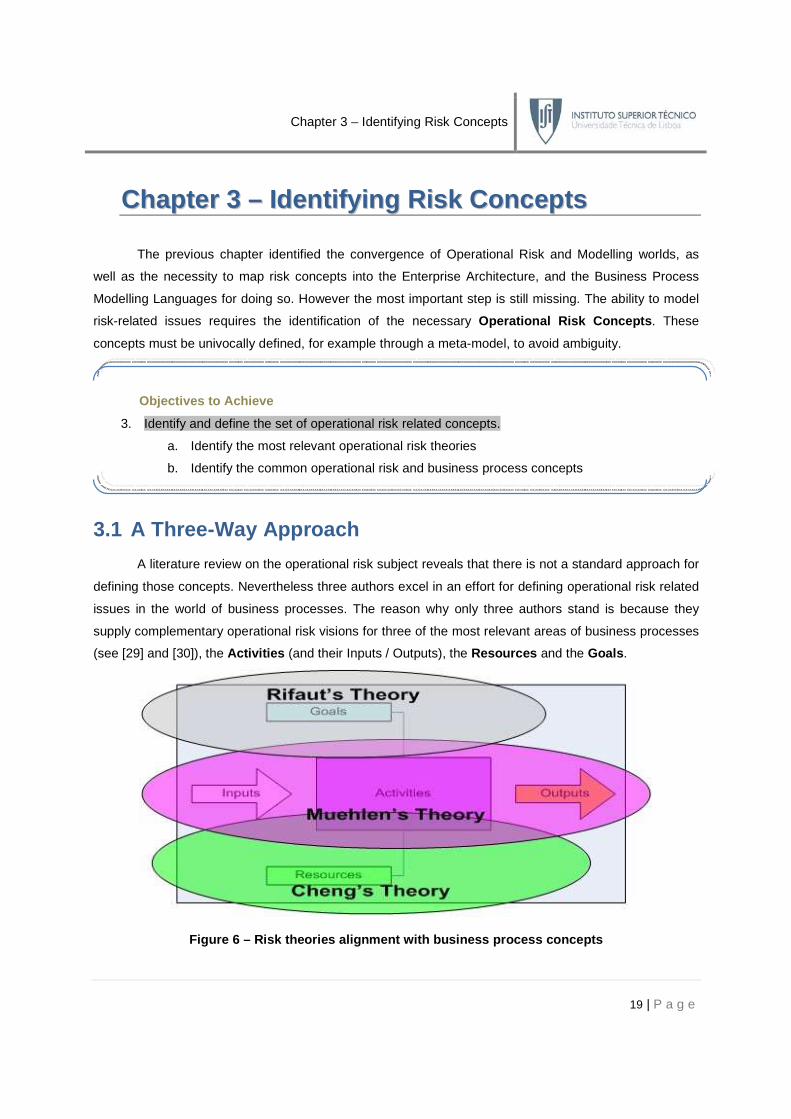
issues in the world of business processes. The reason why only three authors stand is because they
supply complementary operational risk visions for three of the most relevant areas of business processes
(see [29] and [30]), the Activities (and their Inputs / Outputs), the Resources and the Goals .
Figure 6 – Risk theories alignment with business pr ocess concepts
Objectives to Achieve
3. Identify and define the set of operational risk related concepts.
a. Identify the most relevant operational risk theories
b. Identify the common operational risk and business process concepts

Chapter 3 – Identifying Risk Concepts
20 | P a g e
3.1.1 A Resource-Oriented Perspective
Cheng et al in their “Modelling operational risk in business processes ” [31] work propose a
method for operational risk modelling using a network-based approach. Constructing a probabilistic
network based on the physical and logical infrastructure of the business, it is possible to quantify
operational risk based on the capability of mapping and modelling the business processes. This allows
synchronized adjustments in the operational risk model whenever changes in the business process occur.
Risk methodology
Cheng et al suggest that such an approach can also be used as a basis to evaluate different
countermeasures for operational risk control and mitigation. They propose a methodology in three steps:
identification of risks, quantitative analysis and construction of the control business plan . This
methodology is supported by the following meta-model:
Figure 7 – Cheng’s meta-model for operational risk modelling
• Process –a group of tasks and other processes, enabling hierarchical decomposition into
lower-level processes and tasks;
• Task (Ti) – describes an activity in the business process, with characteristics such as costs,
time to completion, task logic or resources required to execute the task. A business process
describes an orderly flow between the tasks within it;
• Information Artefacts – items that will flow through the process at different stages;
• Resource (ri) – these are entities that tasks require to perform certain functions. It can be
perishable or non-perishable. It can have an assigned availability and costs associated;

Chapter 3 – Identifying Risk Concepts
21 | P a g e
• Forking / decisions – a fork is the branching of an incoming connection to multiple outgoing
connections. An incoming token is replicated for each outgoing branch. A decision is like a fork
except that the selection of the outgoing branch is conditional either on the result of an
expression or on a random selection. A decision may have multiple outgoing connections;
• Merge / join – this is the converse of branching, where multiple input flows come together to
pursue a common output flow. In joining, all tokens arriving through the multiple flows have to
arrive before the common output connection is triggered (AND-logic). In merging, the output
flow is triggered whenever a token arrives through any of the input connections (OR-logic).
Formulation
Event
(Ei)
May trigger a failure. It occurs L times during a certain period of time. It has a severity D
associated, measured, for example, by the length of a resource failure or financial impact.
Events play a central role in this model. We can model this constructs using a direct graph or a
matrix, representing which resource is affected by a particular event, as in this example:
Resources
Events r1 r2 r3 r4
E1 - - x -
E2 - x - x
E3 x - x x
Table 7 – Event / Resource implication matrix
Figure 8 – Event /Resource implication graph
It is also possible to analyse which activities are affected by the absence of a resource.
Task
Resource T1 T2 T3 T4
r1 - - x x
r2 - x x -
r3 - x - -
r4 x x x x
Table 8 – Resource / Task implication matrix

Chapter 3 – Identifying Risk Concepts
22 | P a g e
After the construction of these models it is possible to calculate the Loss Functions associated
with the occurrence of certain events, based on the Cost , Frequency and Severity of the risks
considered. The mathematical postulates used in those calculations are beyond the scope of this work.
Additional complexity has to be added to the formulation when the loss comes from the
combination of different types of loss, depending on structural properties of the underlying business
processes. The notion of Workflow was introduced to support this added complexity:
Workflow
(Fj)
A workflow is associated with a particular ordered sequence of tasks. Each workflow is also
associated with an arrival (flow) rate λj. This is the rate at which the flow passes through the
system. To each pair (Fj ,Tij) which is a part of the flow Fj , we associate a queue B.
This concept allows calculation in complex situation when the loss cost is associated with
Buffers , Tasks or Flows. None of these are relevant for our purpose.
Cheng et al conclude their approach with a validation exercise where the cost is calculated based
on several operational risk models. This solution also comprises the use of countermeasures to reduce
the cost of risk associated events. This could be a useful tool to analyse the tradeoffs between the
investments in those measures versus the cost reduction gained. The use of Key-Performance
Indicators to monitor and calibrate the risk model is also suggested.
3.1.2 An Activity-Oriented Perspective
Muehlen et al “Integrating Risks in Business Process Models ” [32] primary objective is
developing a risk-aware process management methodology . Their work gives particular detail to the
development of risk-aware process modelling techniques. They try to provide taxonomy and modelling
techniques to include risks in business process models both at the process level and at the activity level.
Checkpoint
Cheng et al. suggest a Risk Methodology with their own risk-oriented meta-model to
construct their own mathematical formulation for risk. Their meta-model covers three risk-
oriented concepts (Root Cause , Risk Event and Risk Mitigant ), and three nuclear business
concepts (Resource , Activity and Process ). The Resource gains especial relevance in their
approach, as the absence of one in particular will cause a dependency chain that will ultimately
affect the activities and the processes. They also develop the mathematical formulations for
these calculations, including the use of countermeasures.

Chapter 3 – Identifying Risk Concepts
23 | P a g e
Business Process Taxonomy
The taxonomy that is proposed is supported by a business process meta-model that covers five
views / clusters and also eight core concepts. Refer to Appendix C for the meta-model, concepts and
views / clusters. Muehlen et al provide formal definitions for these:
• Process – is defined as a structured flow of activities, which supports business goals and is
facilitated by data and resources. It requires business objects as input and transforms them
within the process to outputs;
• Transition Conditions – transition conditions specify the control flow (temporal and semantic
relationships) between the activities of a process.
The meta-model highlights the following risk-related issues:
• processes can have different objectives, and these are supported by the activities within a
process. As risks are obviously linked to activities, processes and goals also have to be;
• not only the flow of activities, but also the incoming business objects, data, resources or
information technology are at risk, and by consequence, the process they are linked to;
• the links between the clusters are potential sources of risk as well.
Muehlen et al also identify two lifecycle phases for business processes:
• Build-time , when the layout and input / output requirements of a process are designed;
• Run-time , when instances of the designed process are executed.
While the clusters Goal and Structure are of concern during build-time, the clusters
Organisation , Information Technology and Data gain in significance during run-time (see Appendix C).
Risk Taxonomy
The core part of Muehlen et al work is their risk-oriented taxonomy. Their taxonomy was based in
an intense literature review that identified multiple potential sources or risk (see [32]). Having this in mind,
they suggested a risk meta-model (see Appendix D). In their approach they identify four risk concepts:
Concept Description
Error Unexpected event that triggers one or more consequences.
Consequence Event triggered by an error. It can be triggered by one, or by the combination
of multiple errors.
Risk The probability of an error triggering an unwanted consequence
Mitigation Mechanism Procedure that aims at reducing the probability or the impact of a risk
Table 9 – Risk-related concepts

Chapter 3 – Identifying Risk Concepts
24 | P a g e
It is also possible to realize that all the literature review potential risk sources were grouped into
five categories called Risk Types , one for each cluster in the meta-model.
Risk Type Threat Affects in
Goal Achievement of process and activity objectives Build-time
Structural Integrity of the process design Build-time
Data Data integrity Run-time
Technology System availability Run-time
Organizational Employee performance Run-time
Table 10 – Risk type description
These risks are caused by errors that can be grouped across Error Areas or Error Types. The
notion of Error Type tries to illustrate the situation when errors occur by causes outside the structural and
logical design of the business process, the process context.
Error Type Occurs when Affects in
Skill -based A resource does not possess the skills to execute the activity Run-time
Knowledge -based A resource misjudges the appropriate actions within an activity Run-time
Rule-based The design of the process does not allow for the right actions or the
right behavioural rules are applied in the wrong context Run-time
Force Majeure Unpredictable Run-time
Table 11 – Error type description
Due to the impossibility to completely remove the risks caused by Error Types , Muehlen et al
suggest four Risk Management Strategies :
Strategy Definition Affects in Reduces
Mitigation Implementation of controls that dampen the effects of risk
occurrences, while not completely alleviating them.
Build-time
Run-time
Probability
Magnitude
Avoidance
Eliminates a specific risk before its occurrence. This strategy
is normally realized by trading the risk for other risks that are
less threatening or easier to deal with.
Build-time Probability
Transfer To shift risk or the consequences from one party to another. Build-time Magnitude
Acceptance
Assumption
To adapt to the risk when it becomes a problem. The
enactment of a risk contingency plan is required. Run-time Magnitude
Table 12 – Risk Management Strategies

Chapter 3 – Identifying Risk Concepts
25 | P a g e
Risk aware process modelling
Muehlen et al conclude their work with a risk modelling approach in the ARIS notation [19] and
EPC, by suggesting four complementary models:
Model Description
Risk Structure model Purpos e: provide insights into the hierarchical relationships between risks.
Risk Goal model Purpose : establish the impact of the risks in the business goals.
Risk State model Purpose : depict non-hierarchical interrelationships between risks and the
causal relationships between risks and consequences.
EPCs extended with risks Purpose : assign risks to the individual steps of a business process.
Table 13 – Risk models
3.1.3 A Goal-Oriented Taxonomy
Although Rifaut et al work “Using Goal-Oriented Requirements Engineering for Im proving the
Quality of ISO/IEC 15504 based Compliance Assessmen t Frameworks ” [33], is not directly related
with operational risk meta-modelling, it provides some insights in how goals could be analysed in risk-
aware business processes. As the paper’s title might indicate, the objective of their work is to provide a
formal framework according to which the compliance of business processes against regulations and their
associated requirements can be assessed and measured. To accomplish it, the following was proposed:
• Use the ISO/IEC 15504 [34] standard to sketch the requirements taxonomy framework;
• Support the construction of the framework with the GORE (Goal-Oriented Requirements
Engineering) concepts;
Checkpoint
Muehlen et al suggest both, a business process and risk taxonomies for incorporating
the Operational Risk notion on business process modelling. Their taxonomy comprises four
basic concepts; a Risk Type classification is also suggested, as well as a collection of Risk
Management Strategies, to deal with unavoidable risks. Finally four modelling techniques are
suggested for risk. It is important to highlight the activity-oriented nature of this approach. The
activity is the nuclear risk affected concept, and it is the arrival and departure point for all other
risk-aware concepts. Such an approach revealed some limitations in the risk modelling of other
process elements. This issue will be introduced later.

Chapter 3 – Identifying Risk Concepts
26 | P a g e
• Use the framework for eliciting / structuring business process requirements and for assessing /
measuring the compliance of deployed business processes against these requirements.
GORE
Goal-Oriented Requirements Engineering traditional scope has always been linked to the
capture of requirements inherent to software-based systems or information systems. Besides the use of
GORE for capturing the why’s behind those systems, some authors have also considered its use for
understanding business and business process models. The GORE high-level strategic goal models can
be refined in terms of lower level goals that can be used for discovering business requirements on
business processes. In such context GORE is relevant in business process engineering since processes
have goals that must be fulfilled during or after their execution.
ISO/IEC 15504
The ISO/IEC 15504 provides an assessment model against which the assurance aspects of an
organization in terms of realization of its business processes and their contribution to business objectives
can be measured. Moreover, it standardizes the structure of business process assurance aspects making
them applicable to business processes of business domains out of the IT software engineering domain.
The first step is the definition of objectively observable and measurable goals. The ISO/IEC 15504
gives a specific taxonomy of Business Process Goals that are structured into Assurance Aspects .
Then it is possible to build the Process Assessment Model (PAM). A PAM describes each business
process with the Purpose and Outcomes of each Assurance Aspect . The basic concepts are:
• Purpose – describes at a high-level the overall objectives of an Assurance Aspect . It is fully
decomposable into Outcomes ;
• Outcome – an observable achievement of some Assurance Aspect (ex.: something
produced, a change in state, a constraint met). Can be further detailed with Indicators ;
• Indicator – it is a source of objective evidence used to support a judgment about the fulfilment
of one or more Outcomes (ex.: work products, practices or resources).
Structuring BP requirements with GORE and ISO/IEC 1 5504 approaches
The symbiotic use of these two techniques can be done by using a GORE modelling notation
such as i* with the taxonomy of the ISO/IEC 15504. The final result is a diagram modelled with the tabular
notation of 15504 with the symbols of i*. The mapping between those concepts is expressed bellow:
ISO/IEC 15504 i*
Business Goals soft-goals / goals

Chapter 3 – Identifying Risk Concepts
27 | P a g e
Purpose soft-goals
Outcomes goals
Indicators task / resources / actors
Table 14 – ISO/IEC 15504 VS i* concept mapping
Rifaut et al describe the construction procedure of their method in [33], but those steps are not
relevant for the conclusions we are trying to achieve.
The last step of their methodology “Validation and evolution of the models ” is when the i*
models are verified against the 15504 compliance requirements just before writing the final artefacts. The
major contribution for operational risk of their work comes at this stage; the resulting model should be
composed of explicit and bidirectional links. With i* links and bidirectional traceability links, one can
accommodate the evolution of the original document as well as demonstrating the completeness
of the model . This will allow knowing the relationships between business processes and between any
two cells for the intention of requirements elicitation and analysis. Therefore it will be possible to
address the impact in terms of goal variance caused by risk related failures.
3.2 Identifying the Concepts
The previous sections summarized three of the most important works in the Operational Risk
area. The upcoming task is to consolidate the insights given in the three approaches.
First of all it is useful to list all the concepts and keywords referred in each approach:
Checkpoint
Rifaut et al contribution for the Operational Risk issue is not as obvious as the other
two. Their proposal of a Compliance Assessment Framework creates the taxonomy for
describing business process requirements in terms of goals, which can be decomposed
according to four core concepts: Business Goal , Purpose , Outcome and Indicator . Note that
this is not a risk meta-model; their methodology produces a model that due to its characteristics
ensures that the interconnections between goals and business processes are fully traceable
and complete. This traceability links enable the analysis in terms of goal variance caused by
risk failures.
Objectives Completeness
a. Identify the most relevant operational risk theories √

Chapter 3 – Identifying Risk Concepts
28 | P a g e
Concepts and Keywords
Author Business Process related Operational Risk related Other
Che
ng e
t al
• Resource • Activity / Task • Process • Workflow • Information Artefact • Fork / Decision • Merge / Join • Loops
• Root Cause • Risk Event • Risk Mitigant • Risk Reduction • Risk Control • Financial Impact
• Resource Dependency Graph
• Buffer • Proportion
Mue
hlen
et a
l
• Process • Activity • Goal • Metric • Application • Business Object • Process Participant • Transition Condition
• Error • Consequence • Risk • Mitigation Mechanism • Risk Management Strategy • Error Type • Error Area • Risk Type
Rifa
ut e
t al
• Process • Business Goal / Soft-Goal
/ Goal • Task • Resource • Actor
• Assurance Aspect • Purpose • Outcomes • Indicators
Table 15 – Literature Review concepts and keywords
Figure 9 – Colour mapping for business process rela ted concepts
It was possible to create a colour mapping to group the business process related concepts. Since
there is no standard formal definition between thes e approaches, the grouping was supported on
a semantic similarity basis . Five groups of identical concepts were identified: Process , Activity ,
Resource , Goal and Connector . A deeper insight, as well as definitions, is provided on the next chapter.

Chapter 3 – Identifying Risk Concepts
29 | P a g e
R
oot C
ause
Ris
k E
vent
Ris
k M
itiga
nt
Ris
k
Red
uctio
n
Ris
k C
ontr
ol
Fin
anci
al
Impa
ct
Err
or
Con
sequ
ence
Ris
k
Miti
gatio
n
Mec
hani
sm
Ris
k
Man
agem
ent
Str
ateg
y
Err
or T
ype
Err
or A
rea
Ris
k T
ype
Cause related x x x x x x x
Effect related x x x x
Prevention related x x x x x x x
Table 16 – Risk concepts mapping
The risk concepts were grouped in the previous table, along with their semantic similarity:
• Cause related – all concepts that reflect the origins of the risk or the event that propelled it;
• Effect related – all concepts related to the outcomes that the cause triggered;
• Prevention related – all concepts that somehow alleviate the impact of the effect or the
probability of the cause;
A clear mapping of all the concepts but one was made. Risk didn’t find any direct mapping, since
none of the three approaches defines it distinctly, and it is used in a generic and quite divergent way.
By contrasting their approach in terms of content we can further analyse the three approaches:
Topic Chengs’ Muehlens’ Rifauts’
Provides a business process meta-model ● ● -
Provides an operational risk meta-model ○ ● -
Supplies formulations in how to calculate risk probabilities ● ○ -
Supplies formulations in how to calculate loss due to risk ● - -
Provides concepts and taxonomies for the three risk concepts:
Cause
Effect
Prevention
○
●
○
●
●
●
-
-
-
Provides insights in how to model risk related issues - ● -
Provides traceability methods to analyse the risk impact:
Processes
Activities
Resources
Goals
●
●
●
-
●
●
-
●
○
-
-
●

Chapter 3 – Identifying Risk Concepts
30 | P a g e
Connectors ○ ○ -
Legend: ● Extensively covered ○ Moderately covered - Superficially / Not covered
Table 17 – Literature Review check matrix
3.3 Concept and Methodology Overview
The first section of this chapter led us to a series of comparative conclusions, highlighted in the
previous one, through Figure 9, Table 16 and Table 17. Two relevant conclusions can be highlighted:
• the business process related concepts can be grouped in five core common concepts:
Process, Activity (Task), Resource , Goal and Connector ;
• apart from nomenclature, there are three core risk concepts: Cause , Effect and Prevention ;
We can also draw some attention to some parallel issues, such as:
• an operational risk-oriented meta-modelling solution is only possible in a business process
context; this chapter emphasizes it, identifying the concepts necessary to articulate with risk;
• it is yet to be defined how do the operational risk and business process concepts interact;
• although providing mathematical formulations for risk is out of the scope of this work, the
meta-modelling solution in construction should allow their incorporation in the future.
Checkpoint
In this chapter the fundamental elements for the risk-oriented business process meta-
model were identified. This task was the result of a comparative analysis of the main
operational risk trends, by Muehlen et al, Cheng et al and Rifaut et al. These took quite distinct
approaches (activity, resource and goal, respectively), but shared some characteristics that
lead to the identification of the five process-oriented concepts (Process , Activity , Resource ,
Goal and Connector) and the three risk-oriented concepts (Cause , Effect and Prevention) .
However one very important task still is undone. These concepts lack a true formal
definition, and a unifying meta-model still has to be determined.
Objectives Completeness
2. Identify and define the set of operational risk related concepts. √x (partially)
b. Identify the common operational risk and business process concepts √

Chapter 4 – Defining the Concepts
31 | P a g e
CChhaapptteerr 44 –– DDeeff iinniinngg tthhee CCoonncceeppttss
The previous chapters placed us at the standstill point described in the introductory sections. In
an effort to address these risk-oriented issues at Link Consulting SA 14, a meta-model unifying these
concepts has been developed. The KYE (Know Your Enterprise) meta-model (see Appendix E) is an
organizational blueprint which has recently suffered major developments, and that will be used as a
working basis for this thesis, since it congregates the three approaches introduced into one single entity.
4.1 The Three Basic Dimensions
Before defining the basic operational risk and business process concepts it is necessary to recall
to section 2.2.2, and understand the three basic dimensions that allow us to describe such concepts, as
Caetano [17] covers in its work: Syntax , Semantics and Notation . These three dimensions must be well
defined in order to provide a complete description of the meta-modelling concepts analysed in any BPML.
4.1.1 Semantics
“Semantics is the study of meaning. The word "semantics" itself denotes a range of ideas, from the popular to the highly technical. It is often used in ordinary language to denote a problem of understanding that comes down to word selection or connotation.”15
To define the semantic dimension of any model or construct a description of its meaning should
be included. It can be as detailed as needed and natural language should be used (English in this case).
4.1.2 Notation
The notational representation chosen for the concepts is another issue of concern and should
respect any compliance restrictions of the language. Note that the notation dimension is very close to the
14 See: http://www.link.pt 15 Retrieved at 12/03/2009 from: http://en.wikipedia.org/wiki/Semantic
Objectives to Achieve
2. Identify and define the set of operational risk related concepts.
c. Identify a set of definition criteria for the concepts
d. Define the operational risk concepts
e. Define the business process concepts

Chapter 4 – Defining the Concepts
32 | P a g e
semantic dimension, as different pictorial representations imply distinct semantic interpretations.
Concordantly, and due to the visual nature of the graphical business process modelling languages, a very
special attention must be given to this topic. The use of text , colour , lines and size , must follow the
language rules, and any extension to the language basic constructs should be carefully chosen. Finally,
the possibility of using different views should also be considered. Some concepts can be expanded or
collapsed , conditioning semantic analysis. Due to their synergy, these two dimensions (Semantics and
Notation ) may sometimes be analysed simultaneously.
4.1.3 Syntax
“In linguistics, syntax (…) is the study of the principles and rules for constructing sentences in natural languages. In addition to referring to the discipline, the term syntax is also used to refer directly to the rules and principles that govern the sentence structure of any individual language”16
The definition suggested above highlights Syntax as being related to the formal definition,
including rules and principles. In practical terms it is a much broader concept, and a literature review on
the area reveals different types of approaches and concerns. The UML 1.5 Specification [35] is a good
example, expressing the need of Abstract Syntax , Well-formedness Rules and Semantics for meta-
class definitions. By instance, Atkinson et al [36] suggest the following:
Concept Abstract Syntax Concrete Syntax Well -formedness Semantics
Purpose The concepts from which
models are created.
Concrete rendering
of these concepts.
Rules for the application
of the concepts.
Description of
the meaning of
the model.
Table 18 – Adapted from Atkinson’s [36] semantic an d syntactic approach
The proposed approach is a hybridized solution; as such, a syntactic definition of the model and
its constructs should take into account the following concerns:
• the Syntax dimension as a concept that includes both the abstract and concrete aspects, as
well as well-formedness rules;
• besides any contextual description, the definition of the constructs should encompass the:
o connecting concepts – all the concepts connecting to the considered construct must
be specified;
o type of connection – these include different types of relationships the language might
allow, such as composition, aggregation, hierarchies, etc;
o connecting roles – all connections linking two different concepts have to be tagged,
according to the role that one plays to the other;
16 Retrieved at 15/03/2009 from: http://en.wikipedia.org/wiki/Syntax
Chapter 4 – Defining the Concepts
33 | P a g e
• construct attributes should also be described and defined, in terms of:
o type – the attribute types may vary depending on the considered language. As an
example in BPMN there can be String, Boolean, Integer or being user-defined;
o multiplicity – the cardinality of any attribute should be specified as a pair of numbers,
respectively the lower and upper boundaries (0-n);
o stereotypes – when this extensibility mechanism is applied a construct may assume
different facets according to a certain attribute value. This may change the semantics
and notation of the construct, and must be specified;
• the well-formedness rules , that is, the constraints of attributes, constructs and their
relationships should be defined as a set of invariants that have to be satisfied in order for the
construct be meaningful. Examples of this rules are:
o multiplicity – the cardinality between any two connecting concepts should be specified
as a pair of numbers, respectively the lower and upper boundaries (0-n);
o ordering – some languages require that the instances of a particular construct must be
ordered for scanning purposes. This happens especially with associations.
In spite of the numerous business process languages, with different formal definition paradigms,
and a certain grade of variance, they all, more or less, share these common dimensions.
4.2 Operational Risk Concepts
In the last chapter the three areas of interest inside operational risk terminology were identified:
cause, effect and prevention . However, it is necessary to provide formal definitions for these elements,
considering the syntactic and semantic dimensions, since notation is not relevant at this stage, in meta-
model definition. The utilized semantics will be those of UML Class Diagrams (see [24]).
4.2.1 Cause Related
4.2.1.1 The Problem
The risk concept mapping developed in the previous chapter highlighted the necessity of creating
a concept that expressed the idea of risk chain triggering event. Both Cheng et al and Muehlen et al
uttered the importance of such a concept.
Objective Completeness
c. Identify a set of definition criteria for the concepts √

Chapter 4 – Defining the Concepts
34 | P a g e
Recalling section 3.1.1, Cheng defends the existence of two different concepts, Risk Cause and
Risk Event , where the first causes the second. Additionally, a risk event may impact a Resource , an
Activity , a Process or cause Financial Impact , while risk causes may be reduced via countermeasures.
Section 3.1.2 highlighted Muehlen’s approach; here the concepts are Error and Risk , related by
an Error Occurrence relationship, where the former might enable more errors, and the ladder expresses
the occurrence of an error. Muehlen also introduces a series of error and risk taxonomies, in order to
allow concept hierarchies, however the linkage between risk and business process concepts is omitted.
By balancing these approaches we can advance these additional conclusions:
• both authors consider two levels of causes, a Root Cause (Risk Cause in Chengs’, Error in
Muehlens’) and a Cause Event (Risk Event in Chengs’, Error Occurrence in Muehlens’);
• Cheng suggests that the Cause Event has an impact over several business process artefacts
while Muehlen does not specify any impact linkage at all.
4.2.1.2 The Solution
The solution for this problem is addressed in KYE and complemented by David Cunha’s thesis
[37] at Link Consulting, SA. His work relies on improving the KYE Meta-model V7 in its operational risk
area in order to harmonize it with the three studied approaches of risk. His work will be used solely as a
reference since our purpose is to provide the formal concept definitions the meta-model lacks :
Figure 10 – Operational Risk Meta-Model (adapted in UML Class Diagram)
The above meta-model is an adaptation of Cunha’s improvements to KYE meta-model risk area.
It has some slight differences to KYE, and only one concept is suggested for the cause, the Risk Event .
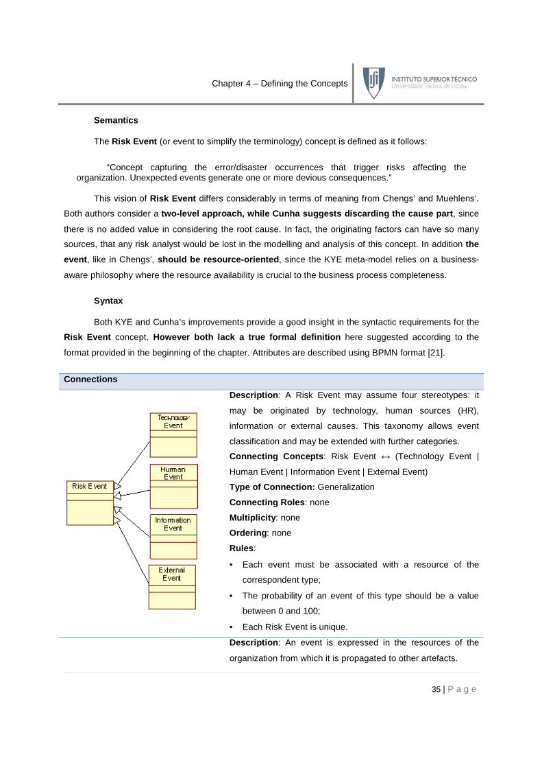
Chapter 4 – Defining the Concepts
35 | P a g e
Semantics
The Risk Event (or event to simplify the terminology) concept is defined as it follows:
“Concept capturing the error/disaster occurrences that trigger risks affecting the organization. Unexpected events generate one or more devious consequences.”
This vision of Risk Event differs considerably in terms of meaning from Chengs’ and Muehlens’.
Both authors consider a two-level approach, while Cunha suggests discarding the cause part , since
there is no added value in considering the root cause. In fact, the originating factors can have so many
sources, that any risk analyst would be lost in the modelling and analysis of this concept. In addition the
event , like in Chengs’, should be resource-oriented , since the KYE meta-model relies on a business-
aware philosophy where the resource availability is crucial to the business process completeness.
Syntax
Both KYE and Cunha’s improvements provide a good insight in the syntactic requirements for the
Risk Event concept. However both lack a true formal definition here suggested according to the
format provided in the beginning of the chapter. Attributes are described using BPMN format [21].
Connecti ons
Description : A Risk Event may assume four stereotypes: it
may be originated by technology, human sources (HR),
information or external causes. This taxonomy allows event
classification and may be extended with further categories.
Connecting Concepts : Risk Event ↔ (Technology Event |
Human Event | Information Event | External Event)
Type of Connection: Generalization
Connecting Roles : none
Multiplicity : none
Ordering : none
Rules :
• Each event must be associated with a resource of the
correspondent type;
• The probability of an event of this type should be a value
between 0 and 100;
• Each Risk Event is unique.
Description : An event is expressed in the resources of the
organization from which it is propagated to other artefacts.

Attributes – Name (Multiplicity)
Risk Event Type (Technology
Event: String
Description : this attribute specifies the type of event considered. It stereoty
according to the four types considered.
Probability : Float
Description : this attribute specifies the probability
specified as a value between 0 and 1
Table
4.2.2 Effect Related
4.2.2.1 The Problem
Both Cheng et al and Muehlen
be mapped somehow in the operational risk meta
Recalling section 3.1.1, Cheng
Impact concept, which can be connected directly through a risk event or indirectly through a resou
activity or process. Muehlen et al
linked to the Error Occurrence , and
The greatest flaw of both of these appro
should the Consequence be mapped in the risk
of them distinguishes different types of consequences and whether
4.2.2.2 The Solution
Having these problems in mind,
Semantics
The Risk Consequence
Chapter 4 – Defining the Concepts
Connecting Concepts : Risk Event ↔
Type of Connection: Association
Connecting Roles : A Risk Event affects
Multiplicity : A Risk Event affects one or more Resources, and
a Resource can be affected by zero or more risks.
Ordering : none
Rules :
• Existing events must affect a resource
) Default Value : Type
(Technology Event | Human Event | Information Event | External Event)
: this attribute specifies the type of event considered. It stereoty
according to the four types considered. The default value is Information Event.
this attribute specifies the probability for the occurrence of an
specified as a value between 0 and 100.
Table 19 – Risk Event syntax definition
Muehlen et al suggested that the generated risk manifestation
the operational risk meta-model however their approaches are quite distinct.
Cheng et al considers the consequence occurrence through the
concept, which can be connected directly through a risk event or indirectly through a resou
et al (see section 3.1.2) states that the Consequence
, and is decomposable into further consequences.
The greatest flaw of both of these approaches is that none of them provide a clear vision of
be mapped in the risk-oriented business process meta
of them distinguishes different types of consequences and whether if it should be business
Having these problems in mind, Cunha embeds KYE with a different approach
Risk Consequence (or consequence to simplify the terminology) concept is defined
36 | P a g e
Resource
affects a Resource.
: A Risk Event affects one or more Resources, and
a Resource can be affected by zero or more risks.
rce.
Event | Information Event | External Event) Information
: this attribute specifies the type of event considered. It stereotypes the risk event
Event.
ence of an event. It should be
suggested that the generated risk manifestation should also
approaches are quite distinct.
considers the consequence occurrence through the Financial
concept, which can be connected directly through a risk event or indirectly through a resource,
Consequence concept is directly
further consequences.
aches is that none of them provide a clear vision of where
oriented business process meta-model. Moreover, none
should be business-aware or not.
embeds KYE with a different approach.
concept is defined as:

Chapter 4 – Defining the Concepts
37 | P a g e
“It is caused by a Risk Event. Describes the damage that a risk event may cause.”
In Cunha’s vision the consequence is a concept that appears in the context of an action-
reaction between an event and a resource . This is an extremely relevant property, as a consequence
cannot exist without this pair of concepts. Similarly to the event, the consequence context is considered
business-aware . This means that the semantics of a consequence should have into consideration
the business artefacts that are linked to the resou rce and the impact in them (such as the activities),
instead of being limited to the consequences for the resource per se. Finally, it is assumed that an event
might enable a series of consequences, with different impacts, among different resources.
Syntax
Connections
Description : In order to express the dependency in the
relationship between a risk event and a resource, there is a
Class Association. Its life cycle is dependent in each link
between a Resource and a Risk Event.
Connecting Concepts : Risk Event ↔ Resource ↔ Risk
Consequence ↔ Risk Event
Type of Connection: Class Association
Connecting Roles : A Risk Event affects a Resource and
generates a Risk Consequence.
Multiplicity : There is one Risk Consequence for each
connection between one Risk Event and one Resource.
Ordering : none
Rules :
• There cannot exist a Risk Consequence outside a Risk
Event and Resource link (life cycle dependency);
• If a Risk Event affects a Resource and generates
multiple Risk Consequences, multiple connections
should be created, one for each Risk Consequence;
• The Quantification value should range from 1 to 4;
Attributes – Name (Multiplicity) Default Value : Type
Risk Consequence : String
Description : this attribute describes the Risk Consequence. It should be business-aware, describing
not only the direct impact in the resource, but also the impact on the business (e.g.: activities).
Quantification : Float
Chapter 4 – Defining the Concepts
38 | P a g e
Description : this attribute describes the magnitude of the potential impact of the Risk Consequence in
a business-aware context. The scale ranges from 1 to 4, according to the operational risk classification
suggested in the Modelo de Avaliação de Riscos by Banco de Portugal [38].
Table 20 – Risk Consequence syntax definition
4.2.3 Prevention Related
4.2.3.1 The Problem
In the selected literature review Muehlen provides the most complete approach (see Table 12)
introducing four adoptable risk-handling strategies: Mitigation, Avoidance, Transfer and Acceptance /
Assumption . These strategies are meant to reduce or eliminate the probability of occurring events or
their impact, providing also an opportunity for positive improvement in performance. Muehlen introduces
this problematic via the Mitigation Mechanism concept, which mitigates an Error Occurrence.
In spite of being the unique relevant contribution from the literature review, Muehlen’s vision is
flawed; first of all in the adopted terminology , where Mitigation should be one of the strategies, not the
concept by its own, and also because the Mitigation Mechanism is supposed to affect both th e
probability and the impact , and the meta-model suggested in his work does not include both.
4.2.3.2 The Solution
The solution relies on improving Muehlen’s approach via the Risk Control (or control) concept in
order to map all this preventive measures.
Semantics
The Risk Control concept is the group of preventive measures for diminishing the
probability of an occurring Risk Event and the impa ct that a Risk Consequence might cause .
These measures can be divided into four categories, the so-called risk-handling strategies as described
by Muehlen et al. Depending on the chosen strategy, a control can affect an event or a consequence,
whether reducing its probability (the first) or its impact (the latter). In this context, a risk control measure
life cycle is dependent on the existence of a risk event or risk consequence. This means that these
measures cannot exist independently of the concepts they aim to act into. Although not explicitly
modelled in the KYE meta-model they will be considered for further development.
Syntax
Connections

Chapter 4 – Defining the Concepts
39 | P a g e
Description : This connection reflects the effect a Risk Control
measure might take by reducing the Risk Consequence impact.
It can assume one of three distinct stereotypes: Mitigation,
Transfer or Acceptance/Assumption.
Connecting Concepts : Risk Consequence ↔ Risk Control
Type of Connection: Association
Connecting Roles : A Risk Control impacts a Risk
Consequence.
Multiplicity : A Risk Consequence might have zero or multiple
Risk Control measures. A Risk Control must be applied to at
least one or more Risk Consequences.
Ordering : none
Rules :
• Only the Mitigation, Transfer or Acceptance/Assumption
stereotypes may be linked to a Risk Consequence;
• The Risk Control life cycle is dependent on the connection
between Risk Control and Risk Consequence;
Description : This connection reflects the effect a Risk Control
might take by reducing the Risk Event probability. It can
assume one of two stereotypes: Mitigation or Avoidance.
Connecting Concepts : Risk Event ↔ Risk Control
Type of Connection: Association
Connecting Roles : A Risk Control impacts a Risk Event.
Multiplicity : A Risk Control must be applied to one or more
Risk Events; Risk Event may have zero or more Risk Controls.
Ordering : none
Rules :
• Only the Mitigation and Avoidance stereotypes may be
linked to a Risk Event;
• The Risk Control life cycle is dependent on the connection
between Risk Control and Risk Event;
Attributes – Name (Multiplicity) Default Value : Type
Strategy (Mitigation | Avoidance | Transfer | Acceptance) Mitigation : String
Description : this attribute specifies the type of strategy of a Risk Control.
Measure s : String

Chapter 4 – Defining the Concepts
40 | P a g e
Description : this attribute should describe in which form the considered Risk Control will reduce the
Risk Event or Risk Consequence. Whether through new activities that are triggered, new resources
allocated or impact / probability reductions, whose attributes should be added, if necessary.
Table 21 – Risk Control syntax definition
4.3 Business Process Concepts
In section 3.2 the group of basic business process elements were identified. These elements were
the result of the comparative meta-modelling colour mappings, and included: Activity , Process ,
Resource , Goal and Connector . It is necessary to understand how these concepts are covered in KYE,
understand how they are related with the operational risk ones, and provide formal definitions.
4.3.1 A Business Process Meta-Model
Again, David Cunha [37] highlights a subset of KYE meta-model concepts that should be
considered in order to cope with operational risk issues. His work was used as a reference for the
purpose of this work, as it congregates the basic elements identified before in a simpler view over KYE.
Below is an adaptation of the suggested business process meta-model, considering four of the
five concepts identifies in the literature review: Process , Activity , Goal and Resource . This occurs
because a deeper analysis revealed that the Connector concept operates in very special conditions, and
is not in the same group as the remaining four. First of all, and as the name suggests, connectors are
support elements for the purpose of establishing business logic within a model. They are also used to
Checkpoint
In this section the three literature review concepts the Cause , the Effect and the
Prevention were formally defined in their syntactic and semantic dimensions, under a new
nomenclature based on KYE meta-model developments made by David Cunha. The Risk
Event , the Risk Consequence and the Risk Control are, in this order, the matching concepts
which constitute the backbone of the Operational Risk Meta-Model. However a nuclear
question still is unanswered:
How will these concepts be integrated with the busi ness process concepts?
Objective Completeness
d. Define the operational risk concepts √

Chapter 4 – Defining the Concepts
41 | P a g e
support the traceability within the model, and not to be traced per se. They are also not risk-exposed ,
and their inclusion as a concept is not relevant in terms of operational risk modelling.
Figure 11 – Business Process Meta-Model (adapted fr om [37])
4.3.2 Business Process Concepts
Since neither KYE nor Cunha’s developments include a formal definition for the business process
concepts, one had to be found. For this purpose Peter Rittgen’s [29] work was used as a reference.
4.3.2.1 Process
Semantics
The definition suggested in Rittgen’s is quite complete for defining what a process is:
“A [business] process is a set of value adding activities that operates over input entities producing output entities. (…) Business processes are orthogonal to the organization’s units. In fact, they frequently cross the boundaries of several units.”
Moreover, a process is directly related with the business goals it aims to reach, being
decomposable in finer Processes or atomic Activities , the finest unit of work.
Syntax
Connections
Description : This connection expresses the
decomposition of a Process into a set of Activities. Since

Chapter 4 – Defining the Concepts
42 | P a g e
an Activity exists in the context of a Process, its life cycle
depends on it. That semantic is expressed with a
Composition link.
Connecting Concepts : Process ↔ Activity
Type of Connection: Composition
Connecting Roles : A Process consists of a set of
Activities.
Multiplicity : A Process is composed by one or more
Activities. An Activity belongs to zero or more Processes.
Ordering : none
Rules :
• An Activity cannot be further decomposed;
• The Activity life cycle is dependent on the Process.
Description : This connection describes the purpose of a
process that is achieving a set of business Goals.
Connecting Concepts : Process ↔ Goal
Type of Connection: Association
Connecting Roles : A Process achieves business Goals.
Multiplicity : A Process is designed to achieve one or
more business Goals for an organization. A Goal may be
achieved by one or more Processes.
Ordering : none
Rules : none
Description : This connection reflects the decomposition
property of Processes, allowing them to have multiple
granularity levels and aggregating multiple sub-Processes.
Connecting Concepts : Process ↔ Process
Type of Connection: Composition
Connecting Roles : A Process may be decomposed in a
group of sub-Processes.
Multiplicity : A Process may be decomposed in multiple
sub-Processes. A sub-Process may be part of one or more
Processes of a higher level.
Ordering : none
Rules :
• A Process always is the highest level concept. It may

Chapter 4 – Defining the Concepts
43 | P a g e
be decomposed in sub-Processes or Activities;
• A sub-Process is a Process of a lower level of
granularity. It is part of a Process, and may be
decomposed in sub-Processes or Activities;
Table 22 – Process syntax definition
4.3.2.2 Activity
Semantics
In Rittgen’s there is a clear semantic definition for the Activity concept, as well as its relationship
with the Business Process concept. Although having a role-centric approach it is similar to other business
process theories seen before. Look at this two extracts from Rittgens’:
“An activity is an abstraction representing how a number of entities collaborate through roles in order to produce a specific outcome . Similarly to an algorithm, an activity aims accomplishing some task which, given an initial state, will always end in finite time an d in a recognizable end-state . (…) An activity specifies what entities are required to realize a task (...). What distinguishes an arbitrary set of coordinated activities from a business process is the fact that the process must add value to some customer , whether internal or external to the organization.”
“An activity describes the business roles required for its operation. These roles are played
by the organization entities and usually include actor role, resource role and observable state role. An activity requires one actor or a combination or tea m of actors to be executed. (…) A resource is used as input or output of an activity during its operation . (…) An observable state is specific resource role that is used as a means to observe the status of an activity. An activity is performed during a specific period .”
Syntax
The syntactic definitions of the Activity relationships are defined in the Process and Resource
sections. Furthermore the syntactic solution suggested, assumes its life cycle is dependent on the
process, always belonging to one, and not existing in a disaggregated and unlinked fashion. Additionally,
activities are always supported by resources; they are always performed by someone or something (a
performer that will be called a Human Resource or Technology Resource depending on the type of the
performer), and can use additional resources for working purposes. Thereby, Rittgen’s role-centric
approach is materialized in the adopted vision through the Resource concept.
4.3.2.3 Resource
Semantics
The Resource assumes a central role in KYE’s developments suggested by Cunha:

Chapter 4 – Defining the Concepts
44 | P a g e
“A Resource is the support of the activity. The referred support could be human, technology, information or other.”
A Resource is in a simplistic way any type of support for the completion of an Activity . It should
be decomposed in three types: a Human Resource , a Technology Resource and an Information
Resource . The Human Resource represents, as the name implies, a human participant in the activity.
Multiple participants may exist. The Technology Resource represents a technological utility used by the
activity, or the performer, if we are in presence of an automatic or semi-automatic activity; applications,
platforms or nodes are examples of it. The ultimate type is the Information Resource representing any
kind of data manipulated by the activity, such as papers, emails, electronic documents, etc.
It is important to underline that the Resource concept is the unique of all business process
concepts that is risk-affected . Thereby, it is the linking concept between these, and the risk concepts.
Syntax
Connections
Description : A Resource may assume three stereotypes, according
to its nature. It may be a Technology Resource, a Human Resource
or an Information Resource.
Connecting Concepts : Resource↔ (Technology Resource |
Human Resource | Information Resource)
Type of Connection: Generalization
Connecting Roles : none
Multiplicity : none
Ordering : none
Rules :
• Each Resource may be linked to a Risk Event of the
corresponding type;
Description : This connection expresses the role of Resources
when an Activity carries out its work. An Activity is supported by a
set of Resources, one being its performer.
Connecting Concepts : Resource ↔ Activity
Type of Connection: Association
Connecting Roles : A Resource supports an Activity.
Multiplicity : An Activity is supported by one or more Resources.
One Resource is allocated on one or multiple Activities.
Ordering : none

Chapter 4 – Defining the Concepts
45 | P a g e
Rules :
An Activity always has at least one supporting Resource, its
performer. A performer must be a Human Resource (manual
Activity), a Technology Resource (automatic Activity) or both (semi-
automatic Activity).
Attributes – Name (Multiplicity) Default Value : Type
Resource Type (Technology Resource | Information Resource | Human Resource) Information
Resource : String
Description: this specifies the stereotype for the given Resource, with default value Information.
Table 23 – Resource syntax definition
4.3.2.4 Goal
Semantics
“A business goal represents a measurable state that the organization intends to achieve. Goals are achieved by the entities involved in performing activities.”
In this definition provided in Rittgen’s, Goals , or more formally Business Goals , are considered
at the business process abstraction level. This means that they will be linked to Processes. However, and
having in mind Rifaut’s taxonomy studied in section 3.1.3 a finer granularity can be achieved. This can be
done by allowing a decomposition of Goals in other Goals and perhaps changing the linkage in the meta-
model from Goals to Activities or keeping it indirectly linked via the Process, creating a hierarchy of
Goals . Although possible, such taxonomy will not be deepened in this thesis.
Syntax
Connections
Description : the decomposition property of a Goal, allows it to
aggregate multiple Goals with independent life-cycles.
Connecting Concepts : Goal ↔ Goal
Type of Connection: Aggregation
Connecting Roles : Goals may be decomposed in Goals.
Multiplicity : A Goal may be decomposed in multiple Goals. A
Goal may be part of one or more Goals of a higher level.
Ordering : none
Rules :
Attributes – Name (Multiplicity) Default Value : Type

Chapter 4 – Defining the Concepts
46 | P a g e
Description : String
Description: this specifies describes the business goal to achieve.
Table 24 – Goal syntax definition
4.4 Operational Risk-Oriented Business Process Meta -Model
This meta-model congregates all the concepts conveyed and defined in the previous sections
(see Appendix F). However it is necessary to analyze the solution from a high-level viewpoint in order to
provide a more complete tool for the modelling procedure that will be addressed on the next chapter.
4.4.1 Bridging the Concepts
As it was referred the linkage between the business process and operational risk concepts is
made via the Resource concept. This concept plays a nuclear part since all the activities are connected
to at least one resource (their performer), and usually multiple of them (the inputs / outputs). Since the
operational risk paradigm is resource-oriented, it is assumed that the Risk Consequences, depending on
their impact, will be propagated towards the other artefacts of the meta-model. This is the basic principle
of the traceability properties outlined in the meta -model ; the possibility to trace back the effects of
an event, navigating into the affected activities, processes and business goals , being a useful tool
to identify bottlenecks or breaking points. This can also be used as a preventive tool; the Risk Control
mechanism can potentially be used as a conditional analysis tool for testing the benefits of measures.
4.4.2 Requirements
This approach assumes that a collection of prerequisites are taken into consideration:
• a business-process paradigm – an organization’s business model must be based in a
process paradigm, thereby it cannot be ruled by other paradigms, such as functional silos ;
Checkpoint
This section introduced the four core business process concepts: Process , Activity ,
Resource and Goal . Due to the lack of formal definition in KYE, their semantic and syntax was
based on Riitgen’s work. In the next section an overview of the entire meta-model is given,
outlining some general characteristics of the suggested solution.
Objective Completeness
e. Define the business process concepts √

Chapter 4 – Defining the Concepts
47 | P a g e
• well -defined business processes – the business processes must be mapped and
documented according to the suggested meta-model and its risk analyzed;
• limited range – this approach assumes that the concepts to be modelled are restricted to
those present in the meta-model in order to avoid compromising the meta-model stability;
• attributes – the set of suggested attributes must be included, although more may be inserted.
4.4.3 Extensibility
The meta-modelling approach was conceived having several extensibility options in thought:
• risk events and resources – only four types of events and three types of resources were
considered relevant in a business process context, however new types of events or resources
may be added if needed, as well as the corresponding linkages;
• taxonomies – as it was highlighted before, Rifaut’s taxonomy of goals may be adopted,
allowing a more structured decomposition of goals. The same stands for the risk concepts;
• attributes – new attributes may be added especially for validation purposes;
• risk formulations – Cheng et al suggest various mathematical formulae for quantifying risk.
These weren’t considered but new attributes may be added to allow such approaches.
Checkpoint
This chapter introduced the basic concepts of the Risk-Oriented Business Process
Meta-Model, based on KYE. The risk related and the business process related concepts were
defined in their semantic and syntactic dimensions; the meta-model was also studied
according to some high-level properties. In the next chapter these concepts will be used as the
input for modelling in a chosen Business Process Modelling Language.
Objectives Completeness
2. Identify and define the set of operational risk related concepts. √

Chapter 5 – Modelling Operational Risk
48 | P a g e
CChhaapptteerr 55 –– MMooddeell ll iinngg OOppeerraatt iioonnaall RRiisskk
Having the concepts semantically and syntactically defined and unified in an Operational Risk-
Oriented Business Process Meta-Model it is now necessary to test their capability of being modelled by
a certain BPML. That issue is addressed in this chapter, by choosing a BPML, by testing it through a
developed methodology and by suggesting a set of notational extensions for it if needed.
5.1 Choosing a Language
In section 2.2 an extensive overview on modelling was made, directing the work towards four
BPMLs: BPMN, UML, EPC and IDEF. Evaluate the modelling capability of each language to the concepts
defined before would provide very accurate results, but the working effort for doing so would be
tremendous, so the unique feasible solution is to choose one of them. However there are no bibliographic
references with formal criteria to choose a language, driving the analysis in more abstract way.
Early
Stages
Last
Specification
Hits
Google Scholar
Total Articles 17
Google Scholar Recent
Articles (>2006)
Actuality
Ratio 18
BPMN 2002 2009 14800 544 233 43%
EPC 1992 1998* 16500 700 261 38%
IDEF 1976 (IDEF3) 1995 3190 603 146 24%
UML 1994 2009 81900 9340 1850 20%
Table 25 – Historic BPML Data
The historic facts show that UML is a real contender, due to its software-oriented roots, and being
used for a wide range of modelling domains. However it is also one of its main criticisms since it is an
adapted business process modelling language, with a significantly difficult learning rate.
17 Retrieved at 15/08/2009 from: http://scholar.google.pt/ 18 Actuality Ratio = (Recent Articles / Total Articles) x 100
Objectives to Achieve
3. Test and contrast these concepts against the modelling capabilities of a chosen mainstream
modelling language.
a. Choose a Business Process Modelling Language
b. Define a testing methodology for mapping the language concepts
c. Apply the methodology to the chosen language
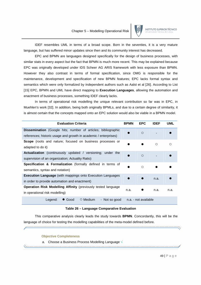
Chapter 5 – Modelling Operational Risk
49 | P a g e
IDEF resembles UML in terms of a broad scope. Born in the seventies, it is a very mature
language, but has suffered minor updates since then and its community interest has decreased.
EPC and BPMN are languages designed specifically for the design of business processes, with
similar stats in every aspect but the fact that BPMN is much more recent. This may be explained because
EPC was originally developed under IDS Scheer AG ARIS framework with less exposure than BPMN.
However they also contrast in terms of formal specification, since OMG is responsible for the
maintenance, development and specification of new BPMN features; EPC lacks formal syntax and
semantics which were only formalized by independent authors such as Aalst et al [26]. According to List
[15] EPC, BPMN and UML have direct mapping to Execution Languages , allowing the automation and
enactment of business processes, something IDEF clearly lacks.
In terms of operational risk modelling the unique relevant contribution so far was in EPC, in
Muehlen’s work [32]. In addition, being both originally BPMLs, and due to a certain degree of similarity, it
is almost certain that the concepts mapped onto an EPC solution would also be viable in a BPMN model.
Evaluation Criteria BPMN EPC IDEF UML
Dissemination (Google hits; number of articles; bibliographic
references; historic usage and growth in academic / enterprises) ● ○ - ●
Scope (roots and nature; focused on business processes or
adapted to do it) ● ● ○ ○
Actualization (continuously updated / versioning; under the
supervision of an organization; Actuality Ratio) ● ○ - ●
Specification & Formalization (formally defined in terms of
semantics, syntax and notation) ● ○ ● ●
Execution Language (with mappings onto Execution Languages
in order to provide automation and enactment) ● ● n.a. ●
Operation Risk Modelling Affinity (previously tested language
in operational risk modelling) n.a. ● n.a. n.a.
Legend: ● Good ○ Medium - Not so good n.a. - not available
Table 26 – Language Comparative Evaluation
This comparative analysis clearly leads the study towards BPMN. Concordantly, this will be the
language of choice for testing the modelling capabilities of the meta-model defined before.
Objective Completeness
a. Choose a Business Process Modelling Language √

Chapter 5 – Modelling Operational Risk
50 | P a g e
5.2 The Language Extension Meta-Process
In order to test BPMN’s capabilities towards operational risk modelling, a testing methodology is
needed. The Language Extension Meta-Process was developed to provide a specific answer for
BPMN. It supports a stage by stage analysis for the language reusability and extensibility issues; this
meta-process will allow the detection of reusable and / or extensible concepts, in order to enable
modelling the concepts identified before. Refer to Appendix I for the complete meta-process.
The meta-process is composed by a series of interlinked activities, grouped in four main areas:
Discovery , Reusability , Extensibility and Acceptance . The purpose is finding a group of candidates ,
whether through extensions or by reusing existing elements , for each of the concepts we want to map
in BPMN. These candidates are thoroughly tested and validated till reaching an acceptance status.
Each of the steps of this meta-process is detailed in the following table:
Stage Description
Dis
cove
ry
The purpose of this activity is to find a match between the concepts
identified before and the equivalent concepts in BPMN. The most suitable
concepts are chosen as candidates for testing purposes.
If reusable candidates were found the Reusability area should be chosen.
Otherwise, the Extensibility area should be chosen.
Reu
sabi
lity
In this activity, the syntactic, notational and semantic restrictions for the
candidates are tested. Such restrictions should include:
• syntactic coherence between the concept and candidate (such as
connections, attributes or well-formedness rules);
• semantic coherence between the concept and candidate;
• notational coherence.
If, during the Reusability activities, a significant misalignment was found,
then the candidates proved to be unusable for mimicking the desired
behaviour. Otherwise the candidates are considered valid for acceptance.
If the validation of the candidates failed, then two paths are possible:
Reusability or Extensibility . In the first new reusable candidates may be
chosen and the process redone; in the second we can extend the language,
either by creating new extensions or by extending the existing ones.
Identify reusablecandidates
Reusable candidates?
Validate Semantics,Notation and Syntax
Valid candidates?
Extend language?

Chapter 5 – Modelling Operational Risk
51 | P a g e
Ext
ensi
bilit
y
In this activity, the extensibility restrictions for BPMN are identified. Such
restrictions should specify the extensional borderline:
• semantic restrictions (new concepts, new meanings, new profiles);
• syntactic restrictions (new attributes, new connections, new rules);
• notational restrictions (new symbols, new colours / text / lines, etc).
Here the notational extensions should be conceived, whether by changing
the existing candidates or by creating new concepts.
At this stage, the compliance between the proposed extensions and the
extensibility restrictions is verified.
If, during the Extensibility activities, a set of valid and satisfactory
extensions has been developed, then they should now be re-tested versus
their syntactic and semantic compliance with the language requirements.
If no new valid extensions were verified, then there are two options: or new
extensions are proposed or, if due to the language restrictiveness none are
possible to develop, the meta-process may be concluded.
Acc
epta
nce
At this final stage the extensions are considered ready to be validated and
formalized in the language specification format. If the proposed solution is
not satisfactory the meta-process may be reinitiated and pruned.
Table 27 – The Language Extension Meta-Process meth odology
5.3 Applying the Meta-Process
The meta-process instantiation is the core procedure of this thesis. It validates the meta-process,
tests BPMN’s capability in modelling the concepts, and provides notational extensions where needed.
This section is centred on a stage-by-stage application of the meta-process on BPMN.
Identifyextensibilityrestrictions
Proposenotationalextensions
Validateextensibilityrestrictions
Valid extensions?
Choose new extensions?
Acceptcandidates
Objective Completeness
b. Define a testing methodology for mapping the language concepts √
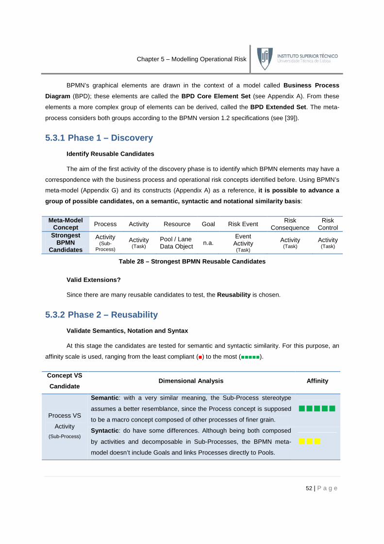
Chapter 5 – Modelling Operational Risk
52 | P a g e
BPMN’s graphical elements are drawn in the context of a model called Business Process
Diagram (BPD); these elements are called the BPD Core Element Set (see Appendix A). From these
elements a more complex group of elements can be derived, called the BPD Extended Set . The meta-
process considers both groups according to the BPMN version 1.2 specifications (see [39]).
5.3.1 Phase 1 – Discovery
Identify Reusable Candidates
The aim of the first activity of the discovery phase is to identify which BPMN elements may have a
correspondence with the business process and operational risk concepts identified before. Using BPMN’s
meta-model (Appendix G) and its constructs (Appendix A) as a reference, it is possible to advance a
group of possible candidates, on a semantic, syntac tic and notational similarity basis :
Meta-Model Concept Process Activity Resource Goal Risk Event
Risk Consequence
Risk Control
Strongest BPMN
Candidates
Activity (Sub-
Process) Activity (Task)
Pool / Lane Data Object n.a.
Event Activity (Task)
Activity (Task)
Activity (Task)
Table 28 – Strongest BPMN Reusable Candidates
Valid Extensions?
Since there are many reusable candidates to test, the Reusability is chosen.
5.3.2 Phase 2 – Reusability
Validate Semantics, Notation and Syntax
At this stage the candidates are tested for semantic and syntactic similarity. For this purpose, an
affinity scale is used, ranging from the least compliant (■) to the most (■■■■■).
Concept VS
Candidate Dimensional Analysis Affinity
Process VS
Activity
(Sub-Process)
Semantic : with a very similar meaning, the Sub-Process stereotype
assumes a better resemblance, since the Process concept is supposed
to be a macro concept composed of other processes of finer grain.
■■■■■
Syntactic : do have some differences. Although being both composed
by activities and decomposable in Sub-Processes, the BPMN meta-
model doesn’t include Goals and links Processes directly to Pools.
■■■

Chapter 5 – Modelling Operational Risk
53 | P a g e
Activity VS
Activity
(Task)
Semantic : with a very similar meaning, the meta-model Activity is
equivalent to BPMN’s Task, which is an atomic, indivisible unit of work. ■■■■■
Syntactic : The BPMN Task is slightly different from the meta-model
Activity, since this has a direct connection to Resource, whereas the
Task is only linked to Data Object (via BPMN Activity) and no Pools.
■■■
Resource VS
Pool / Lane
Semantic : In the meta-model the Human and the Technology Resource
can both be the performers of an activity. BPMN’s Pool represents
business entities or roles, with no technological semantic associated.
■■■■
Syntactic : BPMN’s Pool is related to Processes, while the Human
Resource is related only to the Activity. Functionally the Pool / Lane
linking mechanisms are odd, since they can be both connected by
Message Flows and / or in an overlapping way.
■■■■
Resource VS
Data Object
Semantic : Semantically, the BPMN’s Data Object represents the
Informational and Technology Resources in the risk meta-model
however there is no way to establish a visual distinction between them.
■■■■
Syntactic : Syntactically these concepts are very similar as they can
both be linked to Activities. BPMN’s Data Object has additional syntax,
as it can be part of the flow between Activities.
■■■■■
Goal VS
n.a.
Goals from the risk meta-model do not have any matching candidate in
the BPMN meta-model. This flaw will be addressed later. ■
Risk Event
VS
Event
Semantic : There is a great similarity between these concepts, as both
reflect the notion of something happening, affecting the way an Activity
behaves. However de resemblance is not absolute, since a Risk Event
is resource-oriented, whereas the BPMN Event is activity-oriented.
■■■■
Syntactic : There is a major difference, since the Risk Event affects
Resources, and no similarity exists in BPMN, where events cannot be
linked to Resources (Data Objects or Pool / Lanes), only to Activities.
■
Risk Event
VS
Activity
(Task)
Semantic : These are significantly different since an Activity is a piece
of work that receives inputs, acts, and produces outputs, in a
methodical and structured fashion. Contrastingly the Risk Event is
unpredictable, even though only a subset of events is considered for the
purpose of this work.
■■
Syntactic : They can both be linked to any type of resources, and their
actions can affect them. The BPMN’s Pool / Lane is slightly different,
since it is not interpreted as a traditional Resource.
■■■■

Chapter 5 – Modelling Operational Risk
54 | P a g e
Risk
Consequence
VS
Activity
(Task)
Semantic : In BPMN there is no such concept, and the most similar is
the Activity. A Risk Consequence represents an action that must be
taken in the organization. Only the BPMN’s Activity may mimic such
behaviour, by taking an input and by affecting it in the desired form.
■■
Syntactic : Both of them can be linked to Resources and Events, but
there is no way to quantify / measure the impact on Resources. ■■■
Risk Control
VS
Activity
(Task)
Semantic : Representing a group of measures that affects Risk
Consequences and Events, the Risk Control finds the best resemblance
of his behaviour in BPMN’s Activity, since the latter can be seen as a
set of actions that control how the organization’s artefacts work.
■■■
Syntactic : The Risk Control can be connected to Risk Event and Risk
Consequence. A BPMN Activity can be connected to other Activities
and Events, the candidates for modelling the previous concepts.
■■■■
Table 29 – Concept VS Candidate Affinity Mapping
Valid Candidates?
The previous analysis revealed that some concepts are serious contenders for a no-change,
direct mapping procedure, and other need to be improved or new concepts created.
Concept VS
Candidate
Pro
cess
VS
A
ctiv
ity (S
ub-P
roce
ss)
Act
ivity
VS
A
ctiv
ity (
Tas
k)
Res
ourc
e V
S
Poo
l / L
ane
Res
ourc
e V
S
Dat
a O
bjec
t
Goa
l VS
n.a
.
Ris
k E
vent
VS
E
vent
Ris
k E
vent
VS
A
ctiv
ity (T
ask)
Ris
k C
onse
quen
ce
VS
Act
ivity
(Tas
k)
Ris
k C
ontr
ol
VS
Act
ivity
(Tas
k)
Action Accept Accept Accept Extend New Extend Extend Extend Extend
Table 30 – Concept VS Candidate Validity Check
This table was based on the following evidences:
• neither processes nor activities have 100% compliant candidates in BPMN, but both are
adequate to be accepted, since the mismatches are not significant to justify extensions;
• resources fall in the same category as the previous, but can be improved in order to allow a
distinction between Information and Technology Resources;
• Goals do not have any potential candidate in BPMN. This is a serious misalignment, since
there will be no way to analyse how do Risk Consequences trace back and impact an
organization’s Goal. Concordantly a new concept has to be created;

Chapter 5 – Modelling Operational Risk
55 | P a g e
• Risk Events may be modelled by BPMN Activities or BPMN Events. The first is more adequate
in semantics and the latter in syntax. Both can be potentially extended, and the tradeoffs
between choosing one or the other depend on the extensional restrictions of BPMN;
• Risk Controls and Risk Consequences matching concepts do have some semantic and
syntactic differences that cannot be ignored but can potentially be improved via extensions.
Extend Language?
Since the BPMN concepts revealed important flaws, the extensional mechanism must be initiated.
5.3.3 Phase 3 – Extensibility
Identify Extensibility Restrictions
In order to suppress the flaws, notational extensions must be provided, though with compliance
towards the BPMN extensibility features . These features will play a major role in guiding the
extensions. Based on BPMN specification [39], the following restrictions were formalized as pseudo-rules:
# Description
1 New non-standard elements and Artefacts may be added to satisfy a specific need, as long as their
basic look-and feel is not altered.
2 The footprint of the basic flow elements should not be altered.
Checkpoint
The previous stages of the meta-process highlighted the need of extending BPMN in
order to comply with risk needs and obliging an objective reformulation:
Objective Reformulation
4. Develop an operational risk modelling approach in the chosen business process modelling
language based on the capability results of the previous stage.
5. Validate the approach in a real-world context.
4. Define and formalize a set of improvements (ex.: notational extensions) to the chosen
language in order to enable an operational risk modelling approach.
a. Define a set of notational extensions for the language
5. Validate the extended language in a real-world context, aiming the usage of the newly
developed extensions.
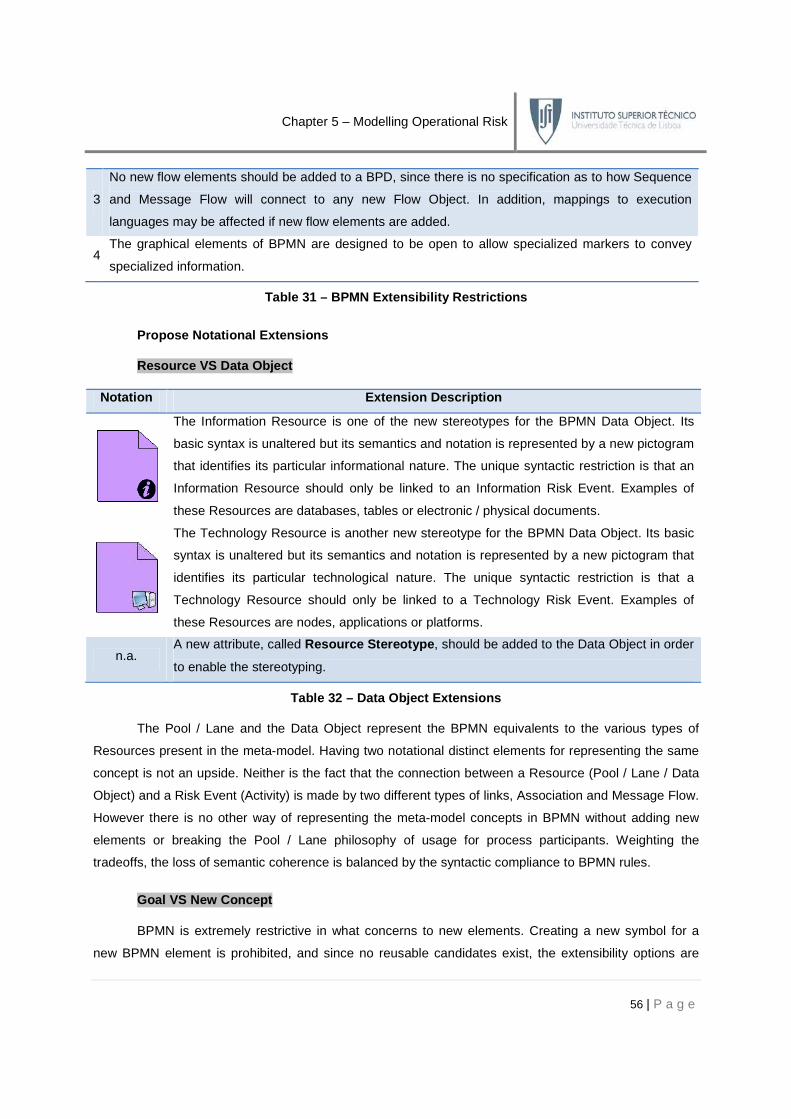
Chapter 5 – Modelling Operational Risk
56 | P a g e
3
No new flow elements should be added to a BPD, since there is no specification as to how Sequence
and Message Flow will connect to any new Flow Object. In addition, mappings to execution
languages may be affected if new flow elements are added.
4 The graphical elements of BPMN are designed to be open to allow specialized markers to convey
specialized information.
Table 31 – BPMN Extensibility Restrictions
Propose Notational Extensions
Resource VS Data Object
Notation Extension Description
The Information Resource is one of the new stereotypes for the BPMN Data Object. Its
basic syntax is unaltered but its semantics and notation is represented by a new pictogram
that identifies its particular informational nature. The unique syntactic restriction is that an
Information Resource should only be linked to an Information Risk Event. Examples of
these Resources are databases, tables or electronic / physical documents.
The Technology Resource is another new stereotype for the BPMN Data Object. Its basic
syntax is unaltered but its semantics and notation is represented by a new pictogram that
identifies its particular technological nature. The unique syntactic restriction is that a
Technology Resource should only be linked to a Technology Risk Event. Examples of
these Resources are nodes, applications or platforms.
n.a. A new attribute, called Resource Stereotype , should be added to the Data Object in order
to enable the stereotyping.
Table 32 – Data Object Extensions
The Pool / Lane and the Data Object represent the BPMN equivalents to the various types of
Resources present in the meta-model. Having two notational distinct elements for representing the same
concept is not an upside. Neither is the fact that the connection between a Resource (Pool / Lane / Data
Object) and a Risk Event (Activity) is made by two different types of links, Association and Message Flow.
However there is no other way of representing the meta-model concepts in BPMN without adding new
elements or breaking the Pool / Lane philosophy of usage for process participants. Weighting the
tradeoffs, the loss of semantic coherence is balanced by the syntactic compliance to BPMN rules.
Goal VS New Concept
BPMN is extremely restrictive in what concerns to new elements. Creating a new symbol for a
new BPMN element is prohibited, and since no reusable candidates exist, the extensibility options are

Chapter 5 – Modelling Operational Risk
57 | P a g e
slim. Two choices are left: either assume the limitation not mapping goals, or create a Goal meta-class ,
with attributes and values, not visible from the BPD viewpoint. We’ll take the second approach.
Notation Extension Description
n.a. A new attribute, called Description , should be added to the new Goal definition.
Table 33 – Goal Extensions
Risk Event VS Event and Risk Event VS Activity
Notation Extension Description
The Risk Event is the proposed new stereotype for the BPMN Activity (Task). Its syntax is
similar as for a regular activity, with some restrictions:
• it can be linked to any of the three types of the corresponding resources;
• it cannot be linked to other activities;
Semantically its meaning represents a negative piece of work that acts over a Resource. A
new pictogram distinguishes it from a regular activity.
n.a. A new attribute, called Risk Stereotype , should be added to the BPMN Activity in order to
enable the usage of the Risk Event. Its value should be set to Risk Event.
n.a. A new attribute, called Probability , should be added to the BPMN Activity (Risk Event
stereotype) in order to express the likelihood of occurrence of the Risk Event.
n.a. A new attribute, called Risk Event Stereotype , should be added to the BPMN Activity to
express the different types of Risk Events (Information, Technology, Human and External).
Table 34 – Activity Extensions
None of the candidates excel in assuming the Risk Event role in terms of reusability. The BPMN
Event is the best semantic candidate however its syntax is severely misaligned in terms of connections (it
cannot be linked to Resources). Reusing the Risk Event would imply adding new flow behaviour to that
element, what is strictly not allowed by the extensibility rules. The BPMN Activity has substantially
different semantics, but its syntax is very similar in terms of valid connections. Although controversial,
syntax overweighs semantics in terms of extensibility rules.
An alternative would have been to use the Exception Flow mechanism of BPMN however a
deeper hindsight reveals profound incompatibilities. Firstly, this mechanism assumes that an alternative
flow exists, what may not be true with untreated Risk Events. Secondly there is no way to distinguish
between various Risk Events; they are all modelled as Exceptions. Finally the Exceptions are attached to
the Activities, being impossible to affect Data Objects or Pool / Lanes (the Resources).

Chapter 5 – Modelling Operational Risk
58 | P a g e
Risk Consequence VS Activity
Notation Extension Description
The Risk Consequence is represented via Association or Message Flow markers, according
to its impact on the Business Process. Four markers were introduced according to MAR [38]:
Reduced Risk [1-1,5[ (Green Marker) | Moderated Risk [1,5-2,5[ (Yellow Marker)
Material Risk [2,5-3,5[ (Orange Marker) | High Risk [3,5-4] (Red Marker)
n.a. A new attribute, called Quantification , should be added to the Risk Consequence definition
in order to measure its potential business impact.
n.a. Since there is no modelling representation two attributes should be added in order to specify
the Risk Consequence originating the Risk Event and the affected Resource.
Table 35 – Association and Message Flow Extensions
A Risk Consequence is the result of the effect of a Risk Event on a Resource. The lack of
syntactic and semantic resemblance with the BPMN Activity, the added modelling complexity and the
BPMN creation restrictions, led the work to not model the Risk Consequence at all. It exists as a meta-
class with attributes and values, and its impact may be visualized through a series of markers that were
added to the Association and Message Flow links, granting those a slightly new semantics.
Risk Control VS Activity
Notation Extension Description
The Risk Control is another proposed stereotype for the BPMN Activity (Task). Its syntax is
similar as for a regular activity, with one restriction:
• it cannot be linked to other activities but Risk Events;
Its semantic meaning is similar to an Activity. It is a set of measures that act over Risk
Events and Risk Consequences in order to reduce their probability and / or impact.
n.a. The attribute Risk Stereotype should be set to the value Risk Control (see Table 34).
n.a. An attribute called Strategy , should be added (Risk Control stereotype) to allow the
specification of one of the four strategies of control (see 3.1.2).
n.a. A new attribute, called Measures , should be added to the BPMN Activity (Risk Control
stereotype) in order to express the control actions that should be taken.
Table 36 – Activity Extensions
A Risk Control can be viewed as a traditional BPMN Activity since it is composed by a set of
actions whose output is the reduction of probability or impact of a certain event or consequence. That can
be viewed as a value-adding activity. Some semantic issues arise since its inputs and outputs, according
to BPMN, should be Resources not Activities. Syntactically all the needed connections are present.

Chapter 5 – Modelling Operational Risk
59 | P a g e
Validate Extensibility Restrictions
Resource VS Data Object
# New Features Compliance
1 Two new Artefacts were added as stereotypes of the Data Object BPMN element. √
2 The footprint of flow elements was not altered. No change
3 No new flow elements were added to the Business Process Diagram. No change
4 Two new markers were added for distinguishing the two added Artefacts. √
- A new attribute was added. √
Table 37 – Resource VS Data Object Extensibility Va lidation
Goal VS New Concept
# New Features Compliance
1 No new elements were added. No change
2 The footprint of flow elements was not altered. No change
3 No new flow elements were added to the Business Process Diagram. No change
4 No new markers were added. No change
- One new definition and one new attribute was added. √
Table 38 – Goal VS New Concept Extensibility Valida tion
Risk Event VS Activity
# New Features Compliance
1 A new stereotype of the BPMN Activity was created. √
2 The footprint of the BPMN Activity was not altered, though some restrictions were
added to its new stereotype, the Risk Event. √
3 No new flow elements were added to the Business Process Diagram. No change
4 One new marker was added for stereotyping the Risk Event. √
- Three new attributes were added. √
Table 39 – Risk Event VS Activity Extensibility Val idation
Risk Consequence VS Activity
# New Features Compliance
1 No new elements were added. No change
2 The footprint of flow elements was not altered. No change
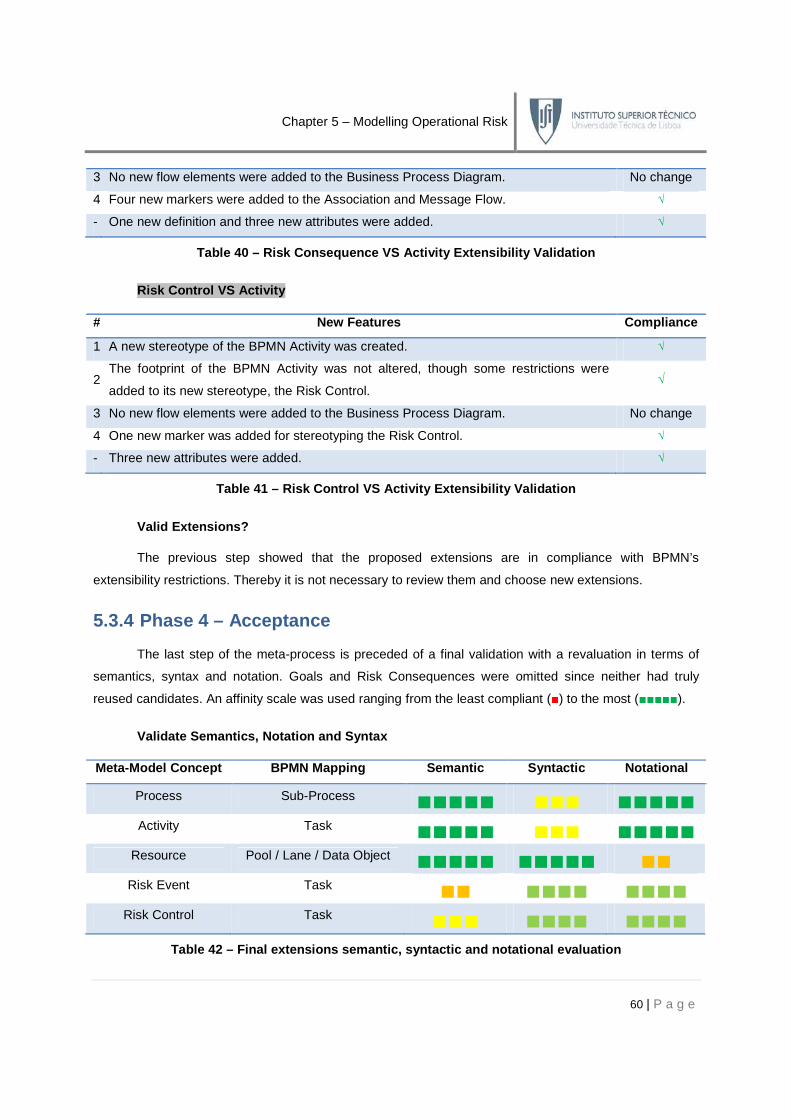
Chapter 5 – Modelling Operational Risk
60 | P a g e
3 No new flow elements were added to the Business Process Diagram. No change
4 Four new markers were added to the Association and Message Flow. √
- One new definition and three new attributes were added. √
Table 40 – Risk Consequence VS Activity Extensibili ty Validation
Risk Control VS Activity
# New Features Compliance
1 A new stereotype of the BPMN Activity was created. √
2 The footprint of the BPMN Activity was not altered, though some restrictions were
added to its new stereotype, the Risk Control. √
3 No new flow elements were added to the Business Process Diagram. No change
4 One new marker was added for stereotyping the Risk Control. √
- Three new attributes were added. √
Table 41 – Risk Control VS Activity Extensibility V alidation
Valid Extensions?
The previous step showed that the proposed extensions are in compliance with BPMN’s
extensibility restrictions. Thereby it is not necessary to review them and choose new extensions.
5.3.4 Phase 4 – Acceptance
The last step of the meta-process is preceded of a final validation with a revaluation in terms of
semantics, syntax and notation. Goals and Risk Consequences were omitted since neither had truly
reused candidates. An affinity scale was used ranging from the least compliant (■) to the most (■■■■■).
Validate Semantics, Notation and Syntax
Meta-Model Concept BPMN Mapping Semantic Syntactic Notational
Process Sub-Process ■■■■■ ■■■ ■■■■■ Activity Task ■■■■■ ■■■ ■■■■■
Resource Pool / Lane / Data Object ■■■■■ ■■■■■ ■■ Risk Event Task ■■ ■■■■ ■■■■
Risk Control Task ■■■ ■■■■ ■■■■ Table 42 – Final extensions semantic, syntactic and notational evaluation

Chapter 5 – Modelling Operational Risk
61 | P a g e
Choose new extensions?
No new extensions will be made, as these fulfil our needs.
Accept Candidates
This last evaluation showed that although major improvements were made towards enabling
operational risk modelling, no perfect solution was found. Despite that, the candidates are considered
accepted for testing in a real-world case study. This will be the last step; if the extensions prove to be
sufficient to model operational risk needs, they will be formalized in BPMN specification format.
5.4 Evaluating the Extensions
As it was referred commitments were made, and syntactic behaviour was the first priority while
reusing and extending the candidates. Syntax outweighs semantics in terms of importance , since
without ensuring that the proper connections are made, the mappings are meaningless. The less elegant
comes by using the BPMN Activity as a Risk Event or Risk Control, since their semantic is not identical.
Similarly, the Resource is flawed, since it has different BPMN elements for linking two types of resources.
Such results were largely influenced by BPMN’s exte nsibility restrictions, but breaking
them was not an option . Such an action would compromise the consistency of this work, creating a new
language that would not be easily comprehended, modelled and automated on BPMN business
processes due to the major effort in creating BPMN to BPEL mappings.
Checkpoint
In this chapter a set of notational extensions were developed for the mainstream BPML
of choice: BPMN. These were the output of the Language Extension Meta-Process , a
systematic algorithm that was developed for BPMN, including a syntactic, semantic and
notational evaluation of the proposed extensions. However BPMN’s extensional restrictions
created several semantic commitments, in order to p rovide full syntactic functionality .
Objectives Completeness
3. Test and contrast these concepts against the modelling capabilities of a chosen
mainstream modelling language. √
c. Apply the methodology to the chosen language √
4. Define and formalize a set of improvements (ex.: notational extensions) to the chosen
language in order to enable an operational risk modelling approach √x (partially)
a. Define a set of notational extensions for the language √

Chapter 6 – Validating an Approach
62 | P a g e
CChhaapptteerr 66 –– VVaall iiddaatt iinngg aann AApppprrooaacchh
In order to confirm the applicability of the suggested notational extensions the approach had to be
tested in a real-world scenario. In fact such validation was made in two distinct ways: one in a practical
exercise, based on Muehlen’s case study; the second through a brainstorming meeting with a European
Investment Fund19 committee, led by the Project Management & Change department, the Management
Advisor José Grincho. For the case study purpose IBM Rational System Architect20 (SA) was selected as
modelling tool, as one of the leading applications in enterprise architectures and BPM.
6.1 The Case Study
The validation of the approach was taken by using System Architect, the modelling tool of choice
for many organizations such as Link Consulting SA. This tool provides a series of valuable features:
• it allows the construction of Business Process Diagrams modelled in BPMN;
• allows creating new definitions and extensions on its meta-model file USERPROPS.TXT;
• supports developing macros on an editor running Visual Basic for Applications 6.521;
• provides reporting mechanisms which allow detailed analysis of the modelled concepts.
Having these in mind, the steps taken for validating the approach were:
1. extend the basic SA meta-model in USERPROPS.TXT, using SA’s internal language;
2. develop a series of validation macros, in a so-called Risk Application, in order to provide an
automatic testing basis for the notational extensions;
3. model the case study using System Architect. This includes modelling the core elements of
BPMN as well as the newly developed extensions and its attributes;
4. apply the validation macros and reports.
19 See: http://www.eif.org 20 See: http://www.telelogic.com/products/systemarchitect/index.htm 21 See: http://msdn.microsoft.com/en-us/isv/bb190538.aspx
Objectives to Achieve
5. Validate the extended language in a real-world context, aiming the usage of the newly
developed extensions.
a. Validate the low-level features
b. Validate the high-level features
Chapter 6 – Validating an Approach
63 | P a g e
6.1.1 The Meta-Model Definition and Extension
The extension of the basic SA definitions was made in USERPROPS.TXT file. Due to its
significant size it was not included in this written document. However due to SA’s implementation
restrictions, the BPMN extensions were not 100% identical the concepts. These limitations were:
• impossibility of establishing syntactic rules to limit the behaviour of some extensions;
• unfeasibility of placing pictograms in the desired locations of the diagram;
• limited property names length;
• inexistence of float values (unless added programmatically);
• impossibility of explicitly insert intervals of values;
• impossibility to associate BPMN Data Objects with Sequence Flows;
• inexistence of BPMN Activities, Tasks or Sub-Processes. Only Processes exist.
6.1.2 The Risk Application
Having the meta-model defined, the next step was to develop a small application, called Risk
Application. This application was conceived with two objectives in mind: firstly, to verify the cohesion of
the approach, by verifying the navigability between the risk and the business process concepts, its
attributes, its connections, and the readability of the overall method; secondly, to prove the added
value of this approach, by running macros that tested the traceability, risk propagation, control activation
or the total risk embedded in a business process. Again, due to the inherent complexity of the developed
code, it was not inserted in this written document. Refer to Appendix J for the application interface.
The interface is composed by two parts; in the top part there are three listboxes, listing all the
events, consequences and controls present in the diagram; depending on which event or consequence is
highlighted, the Probability and Quantification fields will assume different values. The bottom part of the
form is composed by five buttons, with the following purposes:
Functionality Description
Highlight
Event Chain
This functionality scans the diagram for all the relevant connections for the selected
Risk Event, highlighting its links and affected Resource, and calculating its impact in
the business process, by showing the correspondent Risk Consequence impact icon.
Clear All
Highlights
This functionality scans the diagram for any highlighted elements, and sets the state
back to its original colours.
Set Risk
Values
This functionality allows the user to set new probability and quantification values to
the correspondent Risk Event or Risk Consequence.
Get Total Risk This functionality calculates the Total Risk of the business process, an average value
of all the combined impact values calculated from the Risk Events and Risk
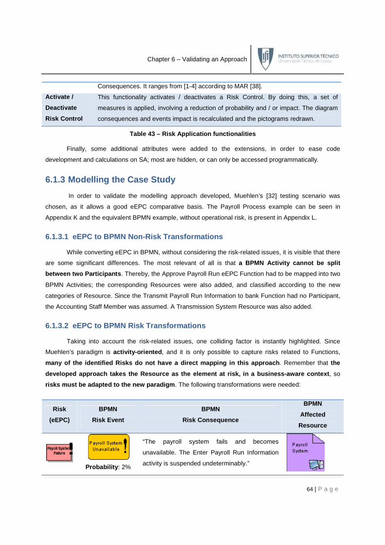
Chapter 6 – Validating an Approach
64 | P a g e
Consequences. It ranges from [1-4] according to MAR [38].
Activate /
Deactivate
Risk Control
This functionality activates / deactivates a Risk Control. By doing this, a set of
measures is applied, involving a reduction of probability and / or impact. The diagram
consequences and events impact is recalculated and the pictograms redrawn.
Table 43 – Risk Application functionalities
Finally, some additional attributes were added to the extensions, in order to ease code
development and calculations on SA; most are hidden, or can only be accessed programmatically.
6.1.3 Modelling the Case Study
In order to validate the modelling approach developed, Muehlen’s [32] testing scenario was
chosen, as it allows a good eEPC comparative basis. The Payroll Process example can be seen in
Appendix K and the equivalent BPMN example, without operational risk, is present in Appendix L.
6.1.3.1 eEPC to BPMN Non-Risk Transformations
While converting eEPC in BPMN, without considering the risk-related issues, it is visible that there
are some significant differences. The most relevant of all is that a BPMN Activity cannot be split
between two Participants . Thereby, the Approve Payroll Run eEPC Function had to be mapped into two
BPMN Activities; the corresponding Resources were also added, and classified according to the new
categories of Resource. Since the Transmit Payroll Run Information to bank Function had no Participant,
the Accounting Staff Member was assumed. A Transmission System Resource was also added.
6.1.3.2 eEPC to BPMN Risk Transformations
Taking into account the risk-related issues, one colliding factor is instantly highlighted. Since
Muehlen’s paradigm is activity-oriented , and it is only possible to capture risks related to Functions,
many of the identified Risks do not have a direct m apping in this approach . Remember that the
developed approach takes the Resource as the elemen t at risk, in a business-aware context , so
risks must be adapted to the new paradigm . The following transformations were needed:
Risk
(eEPC)
BPMN
Risk Event
BPMN
Risk Consequence
BPMN
Affected
Resource
Probability : 2%
“The payroll system fails and becomes
unavailable. The Enter Payroll Run Information
activity is suspended undeterminably.”

Type : Technology
Probability : 5%
Type : Information
Probability : 3%
Type : Human
Probability : 7%
Type : Technology
Probability : 4%
Type : Information
Probability : 2%
Type : Technology
Table
As we can see due to the
Consequences, all the Risks in eEPC had to be restructured
• Mappings – Risks in eEPC are the
Muehlen considers a two
the root cause is not so relevant
• Risk Event r enaming
resource-oriented (information, technology or human
• Affected Resources
corresponding resources, if none existed. This explains the need of a
Chapter 6 – Validating an Approach
Consequence : C1 | Quantification : 2
“Corrupted data is mistakenly inserted in the
Payroll Run Authorization. The Approval Payroll
Run activity is compromised.”
Consequence: C2 | Quantification : 2
“Payroll Supervisors approve the payroll without
realizing the mistake.”
Consequence: C3 | Quantification : 3
Consequence: C4 | Quantification : 3
“The transmission system fails and becomes
unavailable. The Transmit Payroll Run
Information to Bank activity is suspended
undeterminably.”
Consequence: C5 | Quantification : 2
“The signed payroll run transmission is
intercepted.”
Consequence: C6 | Quantification : 4
“The payroll system fails and becomes
unavailable. The Transmit Payroll Run
Information to Bank activity is suspended
undeterminably.”
Consequence: C7 | Quantification : 1
Table 44 – eEPC to BPMN risk transformations
due to the resource-oriented, business-aware nature of Risk Events and Risk
Consequences, all the Risks in eEPC had to be restructured. The explanation comes below:
Risks in eEPC are the counterparts of Risk Events in BPMN.
considers a two-level approach, with both a root cause and the event
not so relevant, only the effect in the Resource will be considered;
enaming – Risk Events were renamed in order to describe a risk that is
riented (information, technology or human-resources), and not
Affected Resources – since the approach is resource-oriented it was necessary to add the
corresponding resources, if none existed. This explains the need of a
65 | P a g e
mistakenly inserted in the
Approval Payroll
without
“The transmission system fails and becomes
unavailable. The Transmit Payroll Run
Information to Bank activity is suspended
ansmission is
“The payroll system fails and becomes
unavailable. The Transmit Payroll Run
Information to Bank activity is suspended
aware nature of Risk Events and Risk
n comes below:
of Risk Events in BPMN. Remember that
both a root cause and the event per se. Since
will be considered;
Risk Events were renamed in order to describe a risk that is
resources), and not activity-oriented;
it was necessary to add the
corresponding resources, if none existed. This explains the need of a Transmission System;

• Risk Consequence description
description should be business
consequences that happened to the
• Probability & Quantification
to enable some calculations in the m
A good example of the transformations done above is
can see it is structured in an activity
analysis to the process highlights that this
while entering data in the Payroll Run Information
Run Authorization resource. In fact
since the root cause (a data entry mistake) is not relevant; it could have been a software malfunction, or
an intentional hacking. The risk is that the document is corrupted, no matter what caused it. The Risk
Consequence is described in a business
meaningless if we consider the big picture. What is relevant is that the
compromised, and what that means in the entire business process. This logic was applied for
6.1.3.3 Rulings of the Business Process
In order to model the risk concepts in BPMN a
some BPMN modelling rules that had to
1. BPMN Activities always belong
2. BPMN Activities always have an incoming and outgoing Sequence and / or Message Flow;
These constraints influence the representation solution for Risk Events and Risk Controls, since
they are BPMN Activity stereotypes.
BPMN Events to both, Risk Events and Risk Controls
added in order to allow the tagging
Figure
Chapter 6 – Validating an Approach
Risk Consequence description – Risk Consequences are business
be business-oriented. This means that it is more
consequences that happened to the business than the effect produced in the resources;
Probability & Quantification – a set of random values were inserted in these fields in order
to enable some calculations in the macro testing.
of the transformations done above is the Data Entry Mistake
ctivity-oriented approach, so a shift in paradigm
analysis to the process highlights that this is the kind of mistake done by the Accounting Staff Member
Payroll Run Information. This means that the risk is embedded in the
resource. In fact the risk can be generalized to Payroll Run Authorization Co
since the root cause (a data entry mistake) is not relevant; it could have been a software malfunction, or
an intentional hacking. The risk is that the document is corrupted, no matter what caused it. The Risk
Consequence is described in a business-aware fashion; in fact, the document being corrupted is
meaningless if we consider the big picture. What is relevant is that the Approval
compromised, and what that means in the entire business process. This logic was applied for
Business Process Diagram
In order to model the risk concepts in BPMN a few last steps had to be made, since there are
some BPMN modelling rules that had to be taken into consideration:
Activities always belong to Pools / Lanes;
Activities always have an incoming and outgoing Sequence and / or Message Flow;
These constraints influence the representation solution for Risk Events and Risk Controls, since
they are BPMN Activity stereotypes. The solution found for this problem was by engaging Start and End
BPMN Events to both, Risk Events and Risk Controls . In addition the BPMN Group element was
added in order to allow the tagging of Risk Events and Risk Controls, thereby facilitating readability.
Figure 12 – BPMN Risk Event Representation
66 | P a g e
Risk Consequences are business-aware; thereby their
more relevant to describe the
effect produced in the resources;
a set of random values were inserted in these fields in order
Data Entry Mistake eEPC Risk. As we
, so a shift in paradigm was needed. A deeper
Accounting Staff Member
. This means that the risk is embedded in the Payroll
Payroll Run Authorization Corrupted
since the root cause (a data entry mistake) is not relevant; it could have been a software malfunction, or
an intentional hacking. The risk is that the document is corrupted, no matter what caused it. The Risk
aware fashion; in fact, the document being corrupted is
pproval Payroll Run activity is
compromised, and what that means in the entire business process. This logic was applied for all Risks.
few last steps had to be made, since there are
Activities always have an incoming and outgoing Sequence and / or Message Flow;
These constraints influence the representation solution for Risk Events and Risk Controls, since
engaging Start and End
BPMN Group element was
of Risk Events and Risk Controls, thereby facilitating readability.
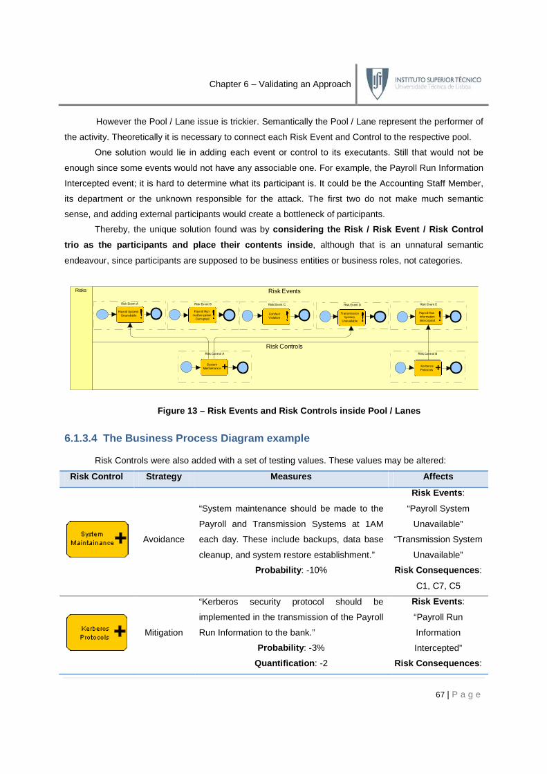
Chapter 6 – Validating an Approach
67 | P a g e
However the Pool / Lane issue is trickier. Semantically the Pool / Lane represent the performer of
the activity. Theoretically it is necessary to connect each Risk Event and Control to the respective pool.
One solution would lie in adding each event or control to its executants. Still that would not be
enough since some events would not have any associable one. For example, the Payroll Run Information
Intercepted event; it is hard to determine what its participant is. It could be the Accounting Staff Member,
its department or the unknown responsible for the attack. The first two do not make much semantic
sense, and adding external participants would create a bottleneck of participants.
Thereby, the unique solution found was by considering the Risk / Risk Event / Risk Control
trio as the participants and place their contents i nside , although that is an unnatural semantic
endeavour, since participants are supposed to be business entities or business roles, not categories.
Figure 13 – Risk Events and Risk Controls inside Po ol / Lanes
6.1.3.4 The Business Process Diagram example
Risk Controls were also added with a set of testing values. These values may be altered:
Risk Control Strategy Measures Affec ts
Avoidance
“System maintenance should be made to the
Payroll and Transmission Systems at 1AM
each day. These include backups, data base
cleanup, and system restore establishment.”
Probability : -10%
Risk Events :
“Payroll System
Unavailable”
“Transmission System
Unavailable”
Risk Consequences :
C1, C7, C5
Mitigation
“Kerberos security protocol should be
implemented in the transmission of the Payroll
Run Information to the bank.”
Probability : -3%
Quantification : -2
Risk Events :
“Payroll Run
Information
Intercepted”
Risk Consequences :
Risks Risk Events
Risk Controls
Payroll RunAuthorization
Corrupted
KerberosProtocols
SystemMaintainance
TransmissionSystem
Unavailable
Payroll RunInformationIntercepted
ConductViolation
Payroll SystemUnavailable
Risk Control BRisk Control A
Risk Event ERisk Event CRisk Event A Risk Event B Risk Event D

Chapter 6 – Validating an Approach
68 | P a g e
C6
Table 45 – Risk Controls in the case study
At last all the operational risk concepts were modelled in System Architect. The complete example
of the case study with risk can be viewed in Appendix M, and property samples consulted in Appendix N.
6.1.4 Applying the Macros and Reports
With the example completely modelled, and properties inserted, the Risk Application was applied
over the BPD. The testing was made according to the evaluating vectors cohesion and added value .
6.1.4.1 Cohesion Testing
“Cohesion is the grammatical and lexical relationship within a text or sentence. Cohesion can be defined as the links that hold a text together and give it meaning.”22
Reporting
The cohesion testing evaluated the modelled business process towards the consistency of the
information modelled, as well as the linkage between its concepts. Three reports were created: the Risk
Event Reporting, the Risk Consequence Reporting and the Risk Control Reporting, all present on
Appendix O. A System Architect report example is also included in the same appendix.
As we can see, the concepts are perfectly intertwined and filled with the required information. The
unique minor adaptations were in the Risk Control, which instead of a Measures attribute had it replaced
with both a Probability and Quantification Reduction for risk calculation purposes.
Macros
The model was tested for navigability by running the Highlight Event Chain macros. The results
are on Appendix P. It is clearly visible that the macro discovers the risk related elements for each Risk
Event, calculating the Risk Impact on the process, by revealing the Risk Consequence symbol. The
algorithm for determination of the severity of the impact was the following (these were test values):
temp = Probability * Quantification
If temp <= 4 Then impact = 1
Else
If temp <= 8 Then impact = 2
Else
If temp <= 12 Then impact = 3
Else impact = 4
End If
End If
End If
22 Retrieved at 12/08/2009 from: http://en.wikipedia.org/wiki/Cohesion_(linguistics)

This algorithm sets the pictogram according to MAR
changed programmatically. The results from the macro are correct, comparing to the manua
Consequence
Quantification (Q) C1 = 2
Risk Event
Probability (P)
2%
Impact
(Q x P)
6.1.4.2 Add ed Value Testing
In order to test the added value of this approach, a series of macros tested the diagram
traceability, edition, and interaction between different concepts.
Risk that calculates the average r
Macro Value:
Manual calculation value:
Here, the Total Risk value calculated for the average of all individual risks is the same for manual
or macro calculation. A more interesting calcul
probability and quantification of both events and consequences.
process is affected, in terms of overall r
Protocols controls. Both, the impact on the corresponding consequences
Macro Value:
Manual calculation value:
6.1.5 Evaluating the Approach
Modelling Evaluation
Completeness (covering a wider range of concepts)
Chapter 6 – Validating an Approach
This algorithm sets the pictogram according to MAR [38]; however the intervals of values
he results from the macro are correct, comparing to the manua
C2 = 2 C3 = 3 C4 = 3 C5 = 2
5%
3%
3%
7%
Figure 14 – Risk Impact Calculations
ed Value Testing
In order to test the added value of this approach, a series of macros tested the diagram
, and interaction between different concepts. The first to be applied was the
that calculates the average risk associated with the entire business process.
Manual calculation value:
value calculated for the average of all individual risks is the same for manual
A more interesting calculation is applying a group of Risk Controls to reduce the
probability and quantification of both events and consequences. Appendix Q reveals how the business
process is affected, in terms of overall risk reduction, by applying the System Maintenance
impact on the corresponding consequences and Total
Manual calculation value:
Approach
Modelling Evaluation
Thi
s
appr
oach
(covering a wider range of concepts) ■■■■■
69 | P a g e
however the intervals of values may be
he results from the macro are correct, comparing to the manual calculations:
C6 = 4 C7 = 1
4%
2%
In order to test the added value of this approach, a series of macros tested the diagram in its
The first to be applied was the Get Total
the entire business process.
Total Risk = 3
value calculated for the average of all individual risks is the same for manual
ation is applying a group of Risk Controls to reduce the
reveals how the business
System Maintenance and Kerberos
otal Risk are reduced:
Total Risk = 2
appr
oach
(BP
MN
)
Mue
hlen
et a
l
(eE
PC
)
■■■■■ ■■
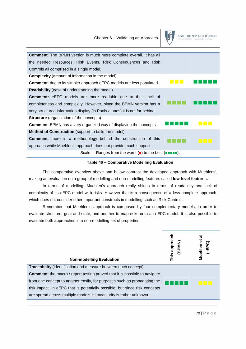
Chapter 6 – Validating an Approach
70 | P a g e
Comment : The BPMN version is much more complete overall. It has all
the needed Resources, Risk Events, Risk Consequences and Risk
Controls all comprised in a single model.
Comple xity (amount of information in the model)
Comment : due to its simpler approach eEPC models are less populated. ■■■ ■■■■■
Readability (ease of understanding the model)
Comment: eEPC models are more readable due to their lack of
completeness and complexity. However, since the BPMN version has a
very structured information display (in Pools /Lanes) it is not far behind.
■■■■ ■■■■■
Structure (organization of the concepts)
Comment : BPMN has a very organized way of displaying the concepts. ■■■■■ ■■■
Method of Construction (support to build the model)
Comment : there is a methodology behind the construction of this
approach while Muehlen’s approach does not provide much support ■■■■ ■■■
Scale: Ranges from the worst (■) to the best (■■■■■).
Table 46 – Comparative Modelling Evaluation
The comparative overview above and below contrast the developed approach with Muehlens’,
making an evaluation on a group of modelling and non-modelling features called low-level features.
In terms of modelling, Muehlen’s approach really shines in terms of readability and lack of
complexity of its eEPC model with risks. However that is a consequence of a less complete approach,
which does not consider other important constructs in modelling such as Risk Controls.
Remember that Muehlen’s approach is composed by four complementary models, in order to
evaluate structure, goal and state, and another to map risks onto an eEPC model. It is also possible to
evaluate both approaches in a non-modelling set of properties:
Non-modelling Evaluation Thi
s ap
proa
ch
(BP
MN
)
Mue
hlen
et a
l
(eE
PC
)
Traceability (identification and measure between each concept)
Comment : the macro / report testing proved that it is possible to navigate
from one concept to another easily, for purposes such as propagating the
risk impact. In eEPC that is potentially possible, but since risk concepts
are spread across multiple models its modularity is rather unknown.
■■■■■ ■■■

Chapter 6 – Validating an Approach
71 | P a g e
Language Compliance (accordance between the extensions and the
restriction mechanisms of the language)
Comment : the proposed extensions are BPMN compliant, although
some semantic and syntactic tradeoffs were made. Due to EPC’s lack of
syntax and semantic formalization any extensional proposal is
acceptable, leaving a huge gap of formality in Muehlen’s approach
■■■■ ■■
Meta-Model Compliance (accordance between the meta-model
suggested and the de facto constructed model with extensions)
Comment: both approaches fail in this task. Muehlen’s by not inserting
Risk Controls and Risk Consequences in the eEPC models, and ours by
failing to map Goals visually in BPMN.
■■■■ ■■■
Risk Interconnection (interconnection between the risk concepts)
Comment : Muehlen’s approach offers a more mature approach on this
topic, by including multiple models that evaluate the structure, goal and
state of risks. However doing this on our work is out of the scope.
■■ ■■■■
Scale: Ranges from the worst (■) to the best (■■■■■).
Table 47 – Comparative Non-Modelling Evaluation
It is not easy to strictly assess which approach is better due to their different scope and since their
meta-model and implementation language is different. A final overview will be made on section 6.3
considering, not only these topics, but also other high-level features.
Checkpoint
The case study revealed how the proposed extensions for BPMN could be used to
model operational risk in a practical example, using Muehlen et al testing case. The resulting
model was tested with a series of macros and reports in order to assess them according to
evaluating vectors: cohesion and added value . This allowed a comparative analysis across
multiple topics with Muehlen’s approach, not only to validate the approach but also to provide a
comparative reference with one of the few similar and most relevant works in the field.
Objective Completeness
c. Validate the low-level features √

Chapter 6 – Validating an Approach
72 | P a g e
6.2 The European Investment Fund
Established in 1994, The European Investment Fund (EIF) is the European Union (EU) body
specialized in small and medium-sized enterprise risk financing. EIF indirectly supports these enterprises
by means of equity and guarantee instruments, in order to improve the availability of risk finance to high
growth and innovation. EIF benefits from AAA-ratings from the three major rating agencies and has the
status of a Multilateral Development Bank which allows financial institutions to apply a 0% risk weighting
under Basel II on assets guaranteed by EIF.
Having the aforementioned experience in risk subjects under Basel II, and in the context of a Link
Consulting SA internal project, occurred a meeting between both institutions, where the content of this
Master Thesis was introduced, discussed and informally validated by this institution’s most reputed
experts. A briefing of this meeting, with the most relevant questions and comments is provided.
Question: “What is this approach about? What is the added value of using it?”
This approach ventures in an area of growing interest of the BPM community but still unexplored
and immature. It unifies a set of risk and business process related concepts and it shows how they can be
modelled in one of the leading business process modelling languages, BPMN. By modelling operational
risk using this approach it is possible to address a series of issues still unanswered in the literature:
• Embed Operational Risk in Business Process Modellin g – the most obvious advantage
is the possibility of visualizing risk issues together with the business process they are
affecting in one of the most used languages, BPMN. All the modelling advantages are
carried over, plus others like enabling impact analysis, calculating risk or risk traceability;
• Compliance with BPMN standards – since the extensions were developed under
compliance with BPMN’s extensibility restrictions it is possible to easily use already
developed BPMN models and complete them with the new extensions. This greatly reduces
their learning rate as well as the creation of possible BPEL mappings;
• Compliance with international standards – this solution was developed having in mind the
standards such as the Basel II Accord or the ISO 31000. In addition, the Operational Risk
Meta-Model was based in the three of the most relevant and complementary research
papers in the field, with combined interest in operational risk and business processes;
• Modelling Tools – this was developed having in mind the benefits of using automatic
modelling tools, such as System Architect, in order to minimize the effort of development and
maximize its payback. By using powerful modelling tools it is possible to easily implement the
BPMN meta-model extensions, as well as macros for risk views or automation via BPEL.

Chapter 6 – Validating an Approach
73 | P a g e
Question: “What is the applicability of this operational risk modelling method in a complex BPMN process? Doesn’t it raise readability and complexity issues?”
This approach is thought to be applied in an automatic environment, using modern modelling tools
such as SA to take full advantage of it. Although possible, it is not recommended its manual usage; an
unsupported background will surely bring up readability and complexity issues as more and more
concepts are added to the models. But that is true in any kind of model, with or without risk. The solution
to this issue is to explore the modelling power of the application, developing views of the business
process. By implementing risk views, it would be possible to analyze just a particular Risk Event, Risk
Control or Risk Consequence, thereby reducing any readability issues that could arise.
Question: “How should this approach be implemented inside an organization?”
This approach assumes that the set of requirements established in 4.4.2 are ensured, as well as:
• business processes are modelled in BPMN ;
• risk-related concepts (events, controls and consequences) are identified . This includes
determining their relationships or attributes according to the meta-model;
• usage of automatic modelling tools with BPMN modelling capabilities and edition of the
existing meta-model possibility. Remember that is necessary to alter the existing BPMN
definitions in order to extend the language. The possibility of developing automatic macros is
also useful, in order to enable risk views and analysis;
Finally it is also assumed that this task is carried out by operational risk and business process
experts, with the know-how for interpreting and developing the specific needs of this work.
Comment: “In our view the Risk Control makes complete semantic sense as a BPMN Activity, independently of BPMN internal semantics. It can be decomposed in a set of elementary actions, consumes inputs, produces outputs and adds value to the organization.”
This comment by the EIF experts proves that the semantic versus syntax dilemma while
extending BPMN has taken the right approach. Although there is an assumed loss of semantics by using
a BPMN primitive to map a concept originally not meant to do it, the fact that the syntactic relationships
are in accordance with the meta-model greatly overweighs that loss. That is evident in the Risk Control,
whose semantics isn’t flawless, but still is very similar to justify the resemblance with the BPMN Activity.

Chapter 6 – Validating an Approach
74 | P a g e
Comment: “Overall we are pleased and looking forward to see further developments. We are open for further cooperation by testing the approach in real-case scenarios.”
This concluded the meeting with EIF, proving the potential applicability in a real-life project, and
validating several context and organizational issues called high-level features .
6.3 Overview
The validation procedure, designed in order to evaluate the low and high-level features
highlighted the intrinsic potential of this approach. If it is true that the low-level features have a
comparative scenario in Muehlen’s work, the high-level features have no possible equivalent, since
Muehlen’s work has not gone through empirical testing yet. Therefore, having the conceptual validation
from EIF was a huge step towards proving this approach. In terms of scope of the meta-model,
Muehlen’s approach differs considerably. His approach only captures risks related to functions while ours,
albeit being resource-oriented has business-aware Risk Consequences, allowing both Resource and
Activity risk sensibility. In terms of applicability , BPMN along with UML is the leading academic and
enterprise language for modelling business processes; this approach’s compliance with international and
BPMN standards, as well as the vast number of modelling tools using BPMN, take it one step ahead of
eEPC. Finally, and although the suggested approach has a series of limitations, there is a great margin of
progress in terms of extensible features (see the last chapter for both).
Checkpoint
In this chapter the Operational Risk-Oriented Business Process Meta-Model extensions
were validated. For this purpose a series of features were evaluated; the low-level features
were tested in a case study based on Muehlen’s work; the high-level features were tested
with one of the most reputed organizations working with risk: the European Investment
Fund . Comparative conclusions were drawn, and the entire approach evaluated. With the
approach validated, the extended language is considered valid to be formalized according to
BPMN’s specification method.
Objectives Completeness
4. Validate the extended language in a real-world context, aiming the usage of the newly
developed extensions. √
a. Validate the high-level features √
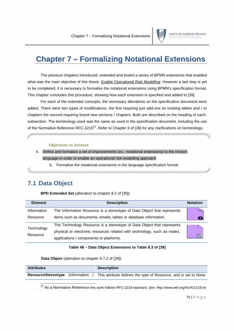
Chapter 7 – Formalizing Notational Extensions
75 | P a g e
CChhaapptteerr 77 –– FFoorrmmaall iizziinngg NNoottaatt iioonnaall EExxtteennssiioonnss
The previous chapters introduced, extended and tested a series of BPMN extensions that enabled
what was the main objective of this thesis: Enable Operational Risk Modelling. However a last step is yet
to be completed; it is necessary to formalize the notational extensions using BPMN’s specification format.
This chapter concludes this procedure, showing how each extension is specified and added to [39].
For each of the extended concepts, the necessary alterations on the specification document were
added. There were two types of modifications, the first requiring just add-ons on existing tables and / or
chapters the second requiring brand new sections / chapters. Both are described on the heading of each-
subsection. The terminology used was the same as used in the specification document, including the use
of the Normative Reference RFC-221923. Refer to Chapter 6 of [39] for any clarifications on terminology.
7.1 Data Object
BPD Extended Set (alteration to chapter 8.2 of [39])
Element Description Notation
Information
Resource
The Information Resource is a stereotype of Data Object that represents
items such as documents, emails, tables or database information.
Technology
Resource
The Technology Resource is a stereotype of Data Object that represents
physical or electronic resources related with technology, such as nodes,
applications / components or platforms.
Table 48 – Data Object Extensions to Table 8.3 of [ 39]
Data Object (alteration to chapter 9.7.2 of [39])
Attributes Description
ResourceStereotype (Information | This attribute defines the type of Resource, and is set to None
23 As a Normative Reference this work follows RFC-2219 standard. See: http://www.ietf.org/rfc/rfc2119.txt
Objectives to Achieve
4. Define and formalize a set of improvements (ex.: notational extensions) to the chosen
language in order to enable an operational risk modelling approach
b. Formalize the notational extensions in the language specification format

Chapter 7 – Formalizing Notational Extensions
76 | P a g e
Technology | None) None : String by default. Depending on the type of Resource, it MAY be
Information or Technology.
Table 49 – Data Object extensions to Table 9.42 of [39]
Information Resource (new chapter 9.7.2.2 on [39])
The Information Resource is one particular stereotype of Data Object that represents physical or
electronic resources such as documents (paper or electronic), emails, tables or database information.
Notation (see the figure on Table 48 ):
o an Information Resource is a portrait-oriented rectangle that has its upper-right corner folded over that
MUST be drawn with solid single black line;
o an Information Resource has a marker (an i) on its bottom-right corner that MUST be drawn in black;
o the use of text, colour and lines for the Information Resource MUST follow the rules defined in [39].
Technology Resource (new chapter 9.7.2.3 on [39])
The Technology Resource is one particular stereotype of Data Object that represents physical or
electronic resources related with technology, such as nodes, applications/components or platforms.
Notation (see the figure on Table 48 ):
o a Technology Resource is a portrait-oriented rectangle that has its upper-right corner folded over that
MUST be drawn with solid single black line;
o a Technology Resource has a marker (a computer) on its bottom-right corner that MUST be drawn;
o the use of text, colour and lines for the Information Resource MUST follow the rules defined in [39].
7.2 Activity
BPD Extended Set (alteration to chapter 8.2 of [39])
Element Description Notation
Risk Event
Risk Event is a stereotype of a Task, representing the occurrence of
an erroneous event on a resource (Data Object or Pool / Lane) and
causing one or more Risk Consequences on a business process.
Risk Control
Risk Control is a stereotype of a Task representing a set of preventive
measures that moderate the risk of a business process, by reducing
the probability or quantification of a Risk Event or Risk Consequence.
Table 50 – Activity extensions to Table 8.3 of [39]

Chapter 7 – Formalizing Notational Extensions
77 | P a g e
Task (alteration to chapter 9.4.3 of [39])
Attributes Description
RiskStereotype (None
| Risk Event | Risk
Control) None : String
The RiskStereotype is an attribute that has a default of None, but MAY be set
to Risk Event or Risk Control. If it is set to None we have a normal Task. If it
is set to Risk Event it will impact the following connections: it MUST have
exactly one incoming Sequence Flow from a Start Event and one outgoing
Sequence Flow to an End Event. It MAY have any number of incoming
Sequence Flow from Risk Controls. It MAY have any number of Association
with any number of Data Objects. It MAY have any number of Message Flow
to any number of Pools / Lanes. It MUST NOT have any other incoming /
outgoing connections other than the specified. If it is set to Risk Control it will
impact the following connections: it MUST have exactly one incoming
Sequence Flow from a Start Event and one outgoing Sequence Flow to an
End Event. It MAY have any number of outgoing Sequence Flow to any
number of Risk Events. It MUST NOT have any other incoming / outgoing
connections other than the specified.
Table 51 – Activity extensions to Table 9.25 of [39 ]
Risk Event (new chapter 9.4.3.11 on [39])
A Risk Event is one particular stereotype of an atomic Activity (Task), representing the occurrence
of an erroneous event on a particular resource (Data Object or Pool / Lane) and causing one or more
Risk Consequences on a business process.
Notation (see the figure on Table 50 ):
o a Risk Event shares the same shape as the Task, which is a rectangle with rounded corners;
o a Risk Event, a rounded corner rectangle, MUST be drawn with a single thin black line;
o a Risk Event MUST have a black exclamation mark drawn inside, on its right side;
o the use of text, colour and lines for the Risk Event MUST follow the rules defined in [39].
Attributes Description
Description : String This is a textual description of the Risk Event. It MUST explicitly explain what
happens to the affected Resource in terms of unavailability or error.
Probability : Integer This specifies the probability of an occurring Risk Event. It MUST be an
integer ranging from 0 to 100.
RiskConsequences (1- This attribute refers to the list of associated Risk Consequences generated by
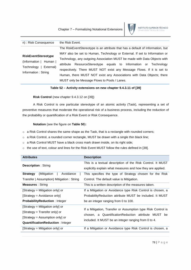
Chapter 7 – Formalizing Notational Extensions
78 | P a g e
n) : Risk Consequence the Risk Event.
RiskEventStereotype
(Information | Human |
Technology | External)
Information : String
The RiskEventStereotype is an attribute that has a default of Information, but
MAY also be set to Human, Technology or External. If set to Information or
Technology, any outgoing Association MUST be made with Data Objects with
attribute ResourceStereotype equals to Information or Technology
respectively. There MUST NOT exist any Message Flows. If it is set to
Human, there MUST NOT exist any Associations with Data Objects; there
MUST only be Message Flows to Pools / Lanes.
Table 52 – Activity extensions on new chapter 9.4.3 .11 of [39]
Risk Control (new chapter 9.4.3.12 on [39])
A Risk Control is one particular stereotype of an atomic activity (Task), representing a set of
preventive measures that moderate the operational risk of a business process, including the reduction of
the probability or quantification of a Risk Event or Risk Consequence.
Notation (see the figure on Table 50 ):
o a Risk Control shares the same shape as the Task, that is a rectangle with rounded corners;
o a Risk Control, a rounded corner rectangle, MUST be drawn with a single thin black line;
o a Risk Control MUST have a black cross mark drawn inside, on its right side;
o the use of text, colour and lines for the Risk Event MUST follow the rules defined in [39].
Attributes Description
Description : String This is a textual description of the Risk Control. It MUST
explicitly explain what measures and how they are applied.
Strategy (Mitigation | Avoidance |
Transfer | Assumption) Mitigation : String
This specifies the type of Strategy chosen for the Risk
Control. The default value is Mitigation.
Measures : String This is a written description of the measures taken.
[Strategy = Mitigation only] or
[Strategy = Avoidance only]
ProbabilityReduction : Integer
If a Mitigation or Avoidance type Risk Control is chosen, a
ProbabilityReduction attribute MUST be included. It MUST
be an integer ranging from 0 to 100.
[Strategy = Mitigation only] or
[Strategy = Transfer only] or
[Strategy = Assumption only] or
QuantificationReduction : Integer
If a Mitigation, Transfer or Assumption type Risk Control is
chosen, a QuantificationReduction attribute MUST be
included. It MUST be an integer ranging from 0 to 4.
[Strategy = Mitigation only] or If a Mitigation or Avoidance type Risk Control is chosen, a

Chapter 7 – Formalizing Notational Extensions
79 | P a g e
[Strategy = Avoidance only]
RiskEvents (1-n) : Risk Event
RiskEvents attribute MUST be included. It specifies the Risk
Events whose Probability will be reduced.
[Strategy = Mitigation only] or
[Strategy = Transfer only] or
[Strategy = Assumption only] or
RiskConsequences (1-n) :
Risk Consequence
If a Mitigation, Transfer or Assumption type Risk Control is
chosen, a RiskConsequences attribute MUST be included. It
specifies the Risk Consequences whose Quantification will
be reduced.
Table 53 – Activity extensions on new chapter 9.4.3 .12 of [39]
Sequence Flow Connections (alteration to chapter 9.4.3.9 of [39])
If a Task has RiskStereotype attribute set to Risk Event, then the following MUST be applied:
o a Risk Event MUST be treated in a parallel flow of the business process. It is instantiated by its
incoming Start Event and it MUST be triggered only once;
o when the Start Event is triggered a token traverses through the Risk Event and enables all the
associated Risk Consequences;
o once the Risk Consequences are done, the flow MUST proceed to the outgoing End Event.
If a Task has RiskStereotype attribute set to Risk Control, then the following MUST be applied:
o a Risk Control MUST be treated in a parallel flow of the business process. It is instantiated by its
incoming Start Event and it MUST be triggered only once;
o when the Start Event is triggered a token traverses through the Risk Control enabling all the
associated preventive actions. These activate the Measures and apply the Quantification and
Probability reductions according to the Strategy, to the relevant Risk Consequences and Risk Events;
o once the Risk Controls are done, the flow MUST proceed to the outgoing End Event.
Message Flow Connections (alteration to chapter 9.4.3.10 of [39])
A Risk Event MAY be the source of a Message Flow if its RiskEventStereotype attribute is set to
Human; it can have zero or more outgoing Message Flows. If there are multiple outgoing Message Flows,
then a single Message will be applied and sent to all the Message Flow.
7.3 Pool / Lane
Swimlanes (Pools and Lanes) (alteration to chapter 9.6.1 of [39])
Attributes Description
ResourceStereotype (Human | This attribute defines the type of Resource. It MAY be Human

Chapter 7
Technology) Human : String
Table 54
7.4 Sequence Flow
Sequence Flow Rules (alteration to
From
Table 55 –
7.5 Message Flow
Message Flow Rules (alteration to
Table 56
Message Flow (alteration to chapter 10.1.3 of
A Message Flow linking a Risk Event
as a result a business Impact. This must be determined by pondering the Risk
SourceRef attribute of Table 10.1 of
formulae to do so must be determined by the risk analyst.
Notation:
o A coloured exclamation mark M
attribute value, according to the following table:
Chapter 7 – Formalizing Notational Extensions
for human activities or Technology, for automatic activities.
54 – Pool / Lane extensions to Table 9.38 of [ 39
Flow
alteration to chapter 8.4.1 of [39])
From \ To
– Sequence Flow extensions to Table 8.4 of [ 39
alteration to chapter 8.4.2 of [39])
From \ To
– Message Flow extensions to Table 8.4 of [ 39
(alteration to chapter 10.1.3 of [39])
A Message Flow linking a Risk Event to a Participant has an associated Risk Consequence and
. This must be determined by pondering the Risk Event
attribute of Table 10.1 of [39]) and the Risk Consequence Quantification
formulae to do so must be determined by the risk analyst.
A coloured exclamation mark MUST be placed next to the Message Flow, depending on the Impact
attribute value, according to the following table:
80 | P a g e
for human activities or Technology, for automatic activities.
39]
39]
39]
a Participant has an associated Risk Consequence and
Event Probability (via the
Quantification (see Table 61). The
UST be placed next to the Message Flow, depending on the Impact

Chapter 7 – Formalizing Notational Extensions
81 | P a g e
Impact Value: [1-1,5[ [1,5-2,5[ [2,5-3,5[ [3,5-4]
Symbol:
Table 57 – Exclamation Mark versus Impact correspon dence
Attributes Description
RiskConsequence (0 -
1) : Risk Consequence
If a Message Flow connects a Risk Event to a Pool / Lane, then it MUST have
an associated Risk Consequence.
[RiskConsequence has
one Risk Consequence
only]
Impact : Integer
The Impact attribute MUST be added if the RiskConsequence attribute has an
associated Risk Consequence. This measures the effective danger a Risk
Event and its Risk Consequence carry to the process. Its value is determined
by weighting the Probability of the Risk Event and the Quantification of its
Risk Consequence. It MUST be an integer ranging from 1 to 4.
Table 58 – Message Flow extensions to Table 10.3 of [39]
7.6 Association
Association (alteration to chapter 10.1.4 of [39])
An Association that links a Risk Event to a Data Object has an associated Risk Consequence and
as a result a business Impact. This must be determined by pondering the Risk Event Probability (via the
SourceRef attribute of Table 10.1 of [39]) and the Risk Consequence Quantification (see Table 61). The
formulae to do so must be determined by the risk analyst.
Notation:
o A coloured exclamation mark MUST be placed next to the Association, depending on the Impact
attribute value, according to Table 57.
Attributes Description
RiskConsequence (0 -
1) : Risk Consequence
If an Association connects a Risk Event to a Data Object, then it MUST have
an associated Risk Consequence.
[RiskConsequence =
Risk consequence only]
Impact : Integer
The Impact attribute MUST be added if the RiskConsequence attribute has an
associated Risk Consequence. This measures the effective danger a Risk
Event and its Risk Consequence carry to the process. Its value is determined
by weighting the Probability of the Risk Event and the Quantification of its
Risk Consequence. It MUST be an integer ranging from 1 to 4.
Table 59 – Association extensions to Table 10.4.1 o f [39]
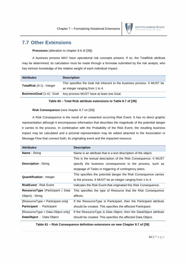
Chapter 7 – Formalizing Notational Extensions
82 | P a g e
7.7 Other Extensions
Processes (alteration to chapter 8.6 of [39])
A business process MAY have operational risk concepts present. If so, the TotalRisk attribute
may be determined; its calculation must be made through a formulae submitted by the risk analyst, who
has intrinsic knowledge of the relative weight of each individual Impact.
Attributes Description
TotalRisk (0-1) : Integer This specifies the total risk inherent to the business process. It MUST be
an integer ranging from 1 to 4.
BusinessGoal (1-n) : Goal Any process MUST have at least one Goal.
Table 60 – Total Risk attribute extensions to Table 8.7 of [39]
Risk Consequence (new chapter 8.7 on [39])
A Risk Consequence is the result of an unwanted occurring Risk Event. It has no direct graphic
representation although it encompasses information that describes the magnitude of the potential danger
it carries to the process. In combination with the Probability of the Risk Event, the resulting business
impact may be calculated and a pictorial representation may be added attached to the Association or
Message Flow that connect both, its originating event and the impacted resource.
Attributes Description
Name : String Name is an attribute that is a text description of the object.
Description : String
This is the textual description of the Risk Consequence. It MUST
specify the business consequences to the process, such as
stoppage of Tasks or triggering of contingency plans.
Quantification : Integer This specifies the potential danger the Risk Consequence carries
to the process. It MUST be an integer ranging from 1 to 4.
RiskEvent : Risk Event Indicates the Risk Event that originated this Risk Consequence.
ResourceType (Participant | Data
Object) : String
This specifies the type of Resource that the Risk Consequence
affects.
[ResourceType = Participant only]
Participant : Participant
If the ResourceType is Participant, then the Participant attribute
should be created. This specifies the affected Participant.
[ResourceType = Data Object only]
DataObject : Data Object
If the ResourceType is Data Object, then the DataObject attribute
should be created. This specifies the affected Data Object.
Table 61 – Risk Consequence definition extensions o n new Chapter 8.7 of [39]

Chapter 7 – Formalizing Notational Extensions
83 | P a g e
Goal (new chapter 8.8 on [39])
Attributes Description
Description : String This is a textual description of the business goal of the business process.
Table 62 – Goal definition extensions on new Chapte r 8.8 of [39]
7.8 Final Notes
The formalization of the developed and validated BPMN extensions was made with few
misalignments from the original conception of the meta-model. Many decisions swerved due to BPMN
extensibility restrictions, but that topic is described on the final chapter.
The extension formalization introduced on this chapter was also inserted in Appendix B of [39],
where the Class Diagram for the BPMN Element Attributes and T ypes extensions is described. The
Class Diagram can be consulted on Appendix R.
Checkpoint
In this chapter the proposed and validated BPMN extensions were formalized according
to BPMN’s specification format present in (33). The attributes and types were specified as
defined previously and the Class Diagram for the languages was also developed. This final
step concludes the long procedure of extending a mainstream business process language
towards operational risk modelling. On the last chapter an evaluation of the work is described,
focusing on the misalignments, future work and conclusions of the work.
Objectives Completeness
4. Provide and formalize a set of improvements (ex.: notational extensions) to the chosen
language in order to enable Operational Risk Modelling. √
b. Formalize the notational extensions in the language specification format √

Chapter 8 – Evaluating an Approach
84 | P a g e
CChhaapptteerr 88 –– EEvvaalluuaatt iinngg aann AApppprrooaacchh
This final chapter evaluates the approach taken throughout this thesis in four main points of
analysis: contributions , misalignments , limitations and future work . These topics grant an unbiased
overview of all the work, assessing not only the contents but also the form and methodology taken.
8.1 Contributions
The most evident added value of this work is stating that the Enable Operational Risk Modelling
main objective was reached. Again its most preeminent features may be divided into a set of high-level
and low-level advantages. The high-level are composed of:
• State of the Art solution – this approach was structured on a meta-modelling solution
based on three of the most relevant and complementary authors in the area;
• Standards compliance – this approach tries to accommodate in one congregated solution
the interests of some of the reference standards in the area, such as Basel II or ISO 31000;
• KYE – this work deepens the developed work of KYE at Link Consulting that united
operational risk with business processes, by providing a modelling solution for it;
• BPMN – this approach uses BPMN as its language of choice, by far one of the most used
languages for business process modelling, with well defined semantics, syntax and notation;
• Automation-Oriented – this work does not discard the enactment fraction, by delivering an
open road for BPEL conversions;
• Validation – the high-level features were validated with a reputed institution, EIF, proving
this works aforementioned potential and applicability.
The low-level contributions include:
• BPMN Meta-Process – an innovative meta-process for extending BPMN was developed,
capturing reusable and extendable candidates, which may prove useful for other languages;
• Concept Fine-Grain Definition – syntactic and semantic definitions were added for the
concepts identified on the literature, and united in KYE;
• BPMN Compliant – the extensions are compliant with the extensional restrictions imposed;
• Validation – the validation of the low-level features were made using a case study based on
a similar method (eEPC), allowing comparisons and measure of results;
• System Architect – the successful definition of a meta-model and its extensions, using a
mainstream modelling tool, with reporting and macro validation methods.

Chapter 8 – Evaluating an Approach
85 | P a g e
8.2 Decisions and Misalignments
The Three-Way Approach
The task of choosing a set of relevant research papers involved a complex process of selection.
Muehlen’s, Rifaut’s and Cheng’s papers were chosen since they provided complementary views and
covered three main areas of process interest, each with a specific operational risk vision.
Grouping and Defining the Concepts
The construction of a common vocabulary using three distinct approaches was complex, since
most concepts were not explicitly defined or had a completely different meaning for each author. The
choice was made on a similarity basis, but that is always a method prone to errors. Their definition was
equally difficult, since the literature review didn’t find out any ontology for doing so; a syntactic, semantic
and notational approximation was taken, but naturally that approach may be incomplete.
Risk Event and Risk Consequence Semantics
The semantic definition of these concepts was quite controversial. Various attempts were tried, in
order to establish a meaningful hierarchy; see the following example:
Figure 15 – Event and Consequence Chain example
The trickiest part of the decision was to determine which of the boxes above corresponds to a
Risk Event and which corresponds to a Risk Consequence. The decision was to consider a business-
aware risk model, where the Risk Consequence expressed the damage to the business process. Such
decision was based on the meaningfulness for the risk analyst, its main stakeholder. The so-called root
causes, whatever and how many they may be, only have significance for determining the Risk Event. In
this case the event is expressed in Machine Unavailable which the business Activity depends on.
The Absence of Goals
Goals were a nuclear concept both of the literature review (Rifaut’s work) and of KYE’s meta-
model. Unfortunately BPMN hasn’t a matching concept, leaving a correspondence vacuum and a major
misalignment. Three options relied; choosing another language, assuming the flaw or extending BPMN:
1. Choosing another language would be contradictory since the blemish only emerged after
the language had been chosen; this would leave the work in a what-if scenario relying on
testing every language till a satisfactory one was found, an obvious source of overwork;

Chapter 8 – Evaluating an Approach
86 | P a g e
2. Assuming the flaw could have been the simplest path, since the semantic and syntactic
approach on Goals places them at the edge of the meta-model, and their absence would
only impact the connected Processes, by disenabling the traceability from Risks to Goals;
3. Extending BPMN would be a possible route but required creating a completely non-
standard element that would break the basic look-and-feel of BPMN elements. List et al
propose in [40] a Process Goal extension, using Pools as the graphical representation for
the Goals. The problem is that Pools are already extended in our approach as Resources.
Therefore the unique viable solution would be implementing Goals as meta-classes with no
new notational representations contradicting the modelling purpose of this work.
Pool and Lane semantics
Glyn Holt (see section 2.1) stated that organizations are not at risk; risk is a condition of
individuals. However the Pool / Lane semantics is not so restrictive, and it may be used to describe both
individuals and groups, generating a misalignment when a Risk Event is modelled affecting a group.
Choosing a Business Process Language
The evaluation criteria for choosing the modelling language were not as formal as pretended. The
problem is that no methodology for choosing the best language for operational risk exists, and for defining
the best approach, all the languages had to be tested, creating an overwork bottleneck.
BPMN Extensibility Meta-Process
The BPMN Extensibility Meta-Process brought up numerous controversial decisions. Remember
that all this decisions were essentially defensible due to BPMN extensibility restrictions. Breaking them
would allow all kind of non-conformant measures, compromising the entire method, and the possibility of
enabling automation through BPEL mappings. The Risk Event mappings with Activities or Events may be
the most evident; remember that although at first glance BPMN Events may seem more adequate, a
deeper insight shows profound syntactic misalignments. Since altering the flow connections is not
allowed, the BPMN Activity was chosen instead, due to an almost perfect syntactic resemblance.
From Meta-Model Concepts to BPMN Specifications
The conversion from a set of theoretical extensions to the formal BPMN specifications, via System
Architect, highlighted numerous implementation differences, such as the need of creating reference
attributes (ex.: a Risk Control must know which Risk Events a Risk Consequence affects), the
impossibility of introducing decimal numbers in SA non-programmatically or name lengths capped to a
predefined size. One of the most relevant misalignments derived from the inability of creating stereotypes
of stereotypes denying the possibility of having four Risk Event categories with a visual representation.

Chapter 8 – Evaluating an Approach
87 | P a g e
8.3 Limitations
This approach still presents a series of limitations:
• Graphical Complexity – without risk views, the analysis of dense diagrams with numerous
events and controls can bring graphical complexity out of hand, therefore the need of views;
• Automation-Oriented – the risk modelling on this approach assumes that it’s going to be
used on an automatic, tool-oriented environment. This can be an advantage due to the
expressive power gained, but it also means that macros for views and risk calculations have
to be developed, with the approach becoming unusable for complex, hand-made models;
• Property Fill-In – in order to run the macros it is necessary to completely fill the attributes
with values, or the risk calculations will be disabled;
• Untested Features – SA’s internal definitions for BPMN and BPMN’s Specification are not
perfectly aligned. SA has a series of implementation limitations such as the absence of non-
decimal numbers or not allowing the alteration of the basic flow of the stereotyped concepts;
• Automatic Activities – theoretically a Technology Resource should have two profiles; in
one it is a support resource in the other it is the performer of the activity. Having two symbols
for the same concept was impossible in SA so they were solely considered as support;
• Semi-Automatic Activities – theoretically a Semi-Automatic Activity must have two
performers one a Human Resource the other a Technology Resource. Unfortunately BPMN
doesn’t allow associations with two Pools, invalidating Semi-Automatic Activities;
• BPMN Extensibility Restrictions – BPMN’s dependency on automation greatly limits the
amount of doable changes, by confining the extensions to attributes, artefacts and a few
shape and colour adjustments. The endeavours for creating semantic and syntactic
compliant solutions were greatly limited in expressiveness;
• BPMN Modelling Rules – the cleanness of the models was greatly limited by the need of
having Pool / Lane organized symbols, and BPMN Events surrounding Task stereotypes;
• The Absence of Visual Goals – the need of having extensions of Goals as meta-classes
guarantees meta-modelling conformance put distorts the meaning of visual modelling;
• System Architect Restrictions – SA has a series of limitations such as the inability to hide /
unhide modelled symbols, disenabling the possibility of creating risk views. The solution was
using coloured symbol views;
• Modelling Validation – the correctness onus is left with the modeller. This means that it is
assumed that the modeller has the know-how to create BPDs with operational risk;
• Validation Procedure – the validation of this work compared two similar languages, BPMN
and eEPC based on different operational risk meta-models, limiting the accuracy of the
results, due to time-limit, overwork and scope restrictions.

Chapter 8 – Evaluating an Approach
88 | P a g e
8.4 Future Work
Having in mind the previous sections we can foresee the following developments:
• Visual Goals – extending BPMN with Goal taxonomies similar to Rifaut’s would be a
significant improvement. How to graphically represent it is another complex issue. List’s [40]
solution collides with ours, unless some kind of Pool / Lane stereotyping is made. That would
be an interesting path to follow, enabling a visual impact traceability on Goals;
• Exploring the BPMN Extensibility Meta-Process – the extensibility meta-process is a
methodology with extreme potential. Developing a common method of extensibility for all the
languages would be an invaluable help for any kind of extensional procedure;
• Developing Risk Views – developing a systematic method for analyzing Risk Events and
Controls is the solution for the complexity issues;
• Probability Macros – developing macros for calculating combined and conditional
probabilities as well as risk control measures would also be a valuable add-on;
• Root Cause – the original cause of the Risk Events have been neglected so far, however a
closer look to the BPD shows that a BPMN Event is originating the Risk Event. KYE meta-
model does not includes such a concept, but other theories, such as Cheng’s do. A possible
development would be stereotyping Root Causes and model them as the BPMN Events that
originated the Risk Event. Other alternative would be by using the Conditional BPMN Start
Event as the Root Cause , specifying a triggering rule for automation and BPEL purposes;
Figure 16 – Route Cause as Conditional BPMN Start E vent example
• Concept Taxonomies – the approach only covers some of the literature taxonomies, such
as the categorization of Risk Controls in four Strategies, or KYE’s Resource stereotypes. It
would be valuable to incorporate the categories or Risk Events in a visual way (remember
the were not implemented due to SA’s limitations) as well as developing other categories;
• Full Automation – this work provides a series of solutions for modelling but in order to
achieve automation (executable business processes), BPEL mappings have to be made. By
being BPMN compliant it is assumed that the extensions have possible BPEL mappings,
although that has not been developed or proved. But a series of BPEL characteristics make
us conjecture that the proposed solution can be enacted:
Payroll SystemUnavailable
ElectricFailure
|
Risk Event A

Chapter 8 – Evaluating an Approach
89 | P a g e
o Conditional Flows – BPEL has the ability to specify Transforms and Assigns
(see [41]) actions, which modify the value of the attributes of any BPMN concept.
By doing this it is possible to guarantee that the events, controls and
consequences can indeed execute their actions;
o Procedure Specification – developers may implement Business Services ,
invoked by Automated Activities in order to enable code-based procedures.
These, just like macros, can be used in order to specify any kind of behaviour;
o Detailed Transformation – when BPMN to BPEL transformation is executed a
much more complex and detailed mapping is made. This means that high-level
Sub-Processes have to be scattered in a series of low-level BPEL actions. This
ensures that step-by-step actions and tests can be made at any time ensuring
that transforms and assigns can be applied when needed.
• BMPN 2.0 – this approach could be adapted to forthcoming versions of BPMN if no
operational risk features are developed by the OMG.
8.5 Conclusions
This work took an end-to-end approach to the identified Operational Risk Modelling issue. The
most relevant outputs of this approach were a set of notational extensions for BPMN that support the
Enable Operational Risk Modelling, in a business process context, core objective. The Risk Event and the
Risk Control are the most noticeable upgrades, but other smaller extensions and parameterizations were
also needed in order to establish an operational risk modelling approach.
Comparing with the established initial objectives some adjustments had to be made. The most
relevant change was related with the development of the operational risk approach. Since extending
BPMN proved to be necessary, a set of activities had to be inserted in order to deal with the extensional
and formalization parts; concordantly those objectives had to be reformulated.
This work highlights two central issues of discussion. The first one questioning if the chosen meta-
model was satisfactory for the purpose of this work, and the second one asking if BPMN was the best
choice. Starting with the last one, BPMN proved to be unsatisfactory to model all the contents present in
KYE meta-model, such as Rifaut’s segment of KYE (the Goals and their taxonomy). This was largely due
to BPMN restrictive extensibility rules, causing a series of semantic and syntactic tradeoffs. However, if
we take into account the existing limitations the approach can be considered satisfying, since of the
seven identified concepts, six had some kind of visual modelling, and complied with the various standards
referred in the literature review.
Contrasting with other languages such as eEPC in Muehlens’, the BPMN approach proved to be
quite reliable. The approach conveyed more information into a single model, had a richer meta-model

Chapter 8 – Evaluating an Approach
90 | P a g e
support and also had series of tested risk calculations using the probabilistic risk attributes. Despite the
proven advantages, that comparison was made using two similar languages with two similar meta-
models, restricting the amount of doable conclusions. In order to provide a trustworthy comparison an
entire eEPC extensional meta-process, using KYE would be needed, providing exactly equal results.
Concordantly two stances can be adopted; either accepting the limitations imposed by BPMN and
modelling it nevertheless or strive for finding out another operational risk solution. This work points out
two important conclusions if we take the last posture; either we assume BPMN is not good enough to
model operational risk or we assume the meta-model is not adequate for doing so. It is hard to tell in
which way this path should be traversed since a given meta-model might not find any fully compatible
BPML and a BPML might not have all the needed concepts to map operational risk. This is the main
criticism with KYE; by not suggesting any BPML for modelling purposes, the task of testing the
operational risk features must be made by trial and error.
Concluding this particular analysis we can say that BPMN proved not to be the perfect solution for
modelling KYE, but that it was reliable enough for providing a solid BPMN compliant solution which was
better than some of the existing risk modelling alternatives, which rely on simpler and less complete meta-
models. We can speculate how well would, eEPC or UML, perform in this matter, but that would require a
time consuming comparison which was clearly out of the scope of this work.
Nonetheless an equitable evaluation of this work brings a bizarre sentiment about the approach.
Since the number of semantic and syntactic tradeoffs to provide a compliant solution was so vast, it
seems that as one door was shut, two windows opened. In fact, any risk analyst who tried using it would
feel a compulsory need of improvement. This is the result of having an intrinsic relationship between
modelling and automation. Modern Business Process Modelling Languages such as BPMN are tool-
oriented and providing modelling extensions without execution in mind is no longer possible.
In one hand this is a great handicap on this thesis, since the work is left in middle; on the other
hand it brings a great sense of relief, since there still is a phenomenal margin of progression, and the
scratches drawn here may be used in a truly innovative operational risk modelling solution.

Bibliography
91 | P a g e
BBiibbll iiooggrraapphhyy 2244
[1]. Defining Risk. Holton, Glyn. 2004, Financial Analysts Journal, pp. 19-25.
[2]. International Organization for Standardization. ISO/DIS 31000 - Risk Management - Principles and
guidelines on implementation. 2008.
[3]. Basel I, Basel II, and Emerging Markets:. Balin, Bryan J. 2008.
[4]. Basel Committee on Banking Supervision. International Convergence of Capital Measurement and
Capital Standards: A Revised Framework. 2005.
[5]. Basel II compliant mapping of operational risks. Schäl, Ingo and Wolfgang, Stummer. 2007, Journal of
Operational Risk, pp. 93-114.
[6]. Holt, Jon. A pragmatic guide to Business Process Modelling. s.l. : BCS, 2005, pp. 1-80.
[7]. Schekkerman, Jaap. Enterprise Architecture Validation: Achieving Business-Aligned and Validated
Enterprise Architectures. [Online] 2003. https://dspace.ist.utl.pt/bitstream/2295/52038/1/Paper1-
Enterprise_Architecture_Validation_Full_version.pdf.
[8]. Spewak, Steven. Enterprise Architecture Planning: Developing a Blueprint for Data, Applications, and
Technology . s.l. : Wiley-QED, 1993.
[9]. Group, The Open. The Open Group Architectural Framework (TOGAF) - Version 8.1. [Online] 2005.
http://www.inst-informatica.pt/servicos/informacao-e-documentacao/biblioteca-digital/arquitectura-de-
empresas/togaf_81_2003_12.pdf.
[10]. A framework for information systems architecture. Zachman, J. s.l. : IBM Systems Journal, 1987, Vol.
26(3).
[11]. In Search of BPM Excellence. The Business Process Management Group. Tampa : Meghan-Kiffer
Press, 2005. 0-929652-40-1.
[12]. Beckler, Jörg and Kugeler, Martin. Process Management. 2003.
[13]. Davenport, Thomas. Process Innovation: Reengineering work through information technology. 1993.
[14]. Havey, M. Essential Business Process Modeling. s.l. : O'Reilly, 2005.
[15]. An Evaluation of Conceptual Business Process Modelling Languages. List, Beate and Korherr, Birgit.
Dijon : ACM, 2006. 1-59593-108.
[16]. On the Ontological Expressiveness of Information Systems Analysis and Design Grammars. Wand, Y.
and Weber, R. s.l. : Journal of Information Systems, 1993, Vol. 3.
[17]. Caetano, Artur. Business Process Modelling with Objects and Roles. 2008.
[18]. Análise da conformidade de Modelos Organizacionais com a norma ISO14258-Concepts and Rules for
Enterprise Models. Tribolet, J. s.l. : 6ª Conferência da Associação Portuguesa de Sistemas de Informação, 2005.
[19]. Scheer, W. ARIS - Business Process Frameworks. Berlin : Springer Verlag, 1998.
[20]. Carlsen, Steinar. Comprehensible Business Process Models for Process Improvement and Process
Support.
24 As a Normative Reference, The bibliography follows the ISO 690 Numerical Reference style

Bibliography
92 | P a g e
[21]. Object Management Group. Business Process Modeling Notation, V1.1 - OMG Available
Specification. [Online] 2008. http://www.omg.org/spec/BPMN/1.1/PDF.
[22]. Russel, Nick, van der Aalst, Wil and Wohed, Petia. On the Suitability of UML 2.0 Activity Diagrams
for Business Process Modelling. 2005.
[23]. Object Management Group. Unified Modeling Language: Infrastructure. [Online] 2006.
http://www.omg.org/cgi-bin/doc?formal/05-07-05.
[24]. —. Unified Modeling Language: Superstructure. [Online] 2006. http://www.omg.org/cgi-
bin/doc?formal/05-07-04.
[25]. R.J.Mayer, C.P.Menzel, M.K. Painter, P.S. deWitte, T. Blinn, B. Perakath. IDEF3 Process
Description Capture Method Report. 1995.
[26]. Formalization and Verification of Event-driven Process Chains. van der Aalst, W.M.P. s.l. : The Journal
of Circuits, Systems and Computers, 1998.
[27]. Scheer, A.-W. and Keller, G. Semantische Prozessmodellierung auf der Grundlage
„Ereignisgesteuerte Prozessketten (EPK). 1991.
[28]. Kindler, Ekkart. On the semantics of EPCs: A framework for resolving the vicious circle. 2003.
[29]. Rittgen, Petter. Enterprise Modeling and Computing with UML. s.l. : IDEA GROUP Publishing, 2007.
[30]. Business Process Extensions to UML Profile For Business Modelling. Tribolet, José, et al. Setubal :
3rd International Conference on Enterprise Information Systems (ICEIS 2001), 2001.
[31]. Modeling operational risk in business processes. Cheng, Feng, et al. 2007, Journal of Operational
Risk, pp. 73-98.
[32]. Integrating Risk in Business Process Models. Muehlen, Michael and Rosemann, Michael. 2005.
[33]. Using Goal-Oriented Requirements Engineering for Improving the Quality of ISO/IEC 15504 based
Compliance Assessment Frameworks. Rifaut, André and Dubois, Eric. 2007.
[34]. ISO/IEC 15504. IT – Process Assessment: Part1 - Part5. 2004.
[35]. Object Management Group. Unified Modeling Language (version 1.5). OMG Object Management
Group. [Online] 1 March 2003. http://www.omg.org/docs/formal/03-03-01.pdf.
[36]. Model-Driven Development:A Metamodeling Foundation. Atkinson, Colin and Kühne, Thomas. 2003.
[37]. Cunha, David. Proposta de Tese de Mestrado. Lisboa : Departamento de Engenharia Informática -
Instituto Superior Técnico, 2009.
[38]. Banco de Portugal. MAR - Modelo de Avaliação de Riscos. 2007.
[39]. Object Management Group. Business Process Modeling Notation (BPMN) Version 1.2. 2009.
[40]. Extending the EPC and the BPMN with Business Process Goals and Performance Measures. Korherr,
Birgit and List, Beate. Funchal : ICEIS (3), 2007. 287-294.
[41]. Juric, Matjaz and Pant, Kapil. Business Process Driven SOA using BPMN and BPEL. Birmingham :
PACKT Publishing, 2008. 978-1-84719-146-5.

AAppppeennddiixx AA –– BBPPMMNN CCoName
Flow Objects These are the main graphical elements to define the behaviour of a business process.
Events An Event is something that happens
process and usually have a cause (trigger) or an impact (result).
Activities It is a generic term for work that company performs. An activity can be atomic or n
Gateways A Gateway is used to control the divergence and convergence of Sequence Flow. Thus, it will
determine branching, forking, merging, and joining of paths.
Connecting Objects They are used for connecting the Flow Objects to each othe
Sequence Flow It is used to show the order of the
Message Flow It is used to show the flow of the
Association An Association is used to assoc
Flow Objects can be associated with Flow Objects.
Swimlanes They are used for grouping the primary modelling elements.
Pool A Pool represents a participant in a process. Also acts as a swimlane
container for partitioning a set of activities from other Pools.
Lane A Lane is a sub-partition within a Pool and will extend the entire length of the Pool, either
vertically or horizontally. Lanes are used to organize and categorize ac
Artifacts These are used to provide additional information about the process. Modellers or modelling tools are free to add new Artifact
Data Object These do not have any direct effect on the flow of the process, but they do provide informa
about what activities require to be performed and/or what they produce.
Group A grouping of activities that are within the same category.
Annotation These are used by a modeller to provide additional information
Table 63
Appendix A – BPMN Core Notation Elements
Coorree NNoottaatt iioonn EElleemmeennttss Description
These are the main graphical elements to define the behaviour of a business process.
ppens during the course of a process. They affect the flow of the
process and usually have a cause (trigger) or an impact (result).
It is a generic term for work that company performs. An activity can be atomic or non-atomic.
A Gateway is used to control the divergence and convergence of Sequence Flow. Thus, it will
determine branching, forking, merging, and joining of paths.
They are used for connecting the Flow Objects to each other or other information.
of the activities that will be performed in a process.
the messages between two participants.
An Association is used to associate information with Flow Objects. Text and graphical non-
Flow Objects can be associated with Flow Objects.
They are used for grouping the primary modelling elements.
A Pool represents a participant in a process. Also acts as a swimlane and a graphical
container for partitioning a set of activities from other Pools.
partition within a Pool and will extend the entire length of the Pool, either
vertically or horizontally. Lanes are used to organize and categorize activities.
These are used to provide additional information about the process. Modellers or modelling tools are free to add new Artifact
These do not have any direct effect on the flow of the process, but they do provide information
about what activities require to be performed and/or what they produce.
A grouping of activities that are within the same category.
These are used by a modeller to provide additional information for the reader.
– BPMN core notation element set (adapted from [39] )
93 | P a g e
Symbol
These are used to provide additional information about the process. Modellers or modelling tools are free to add new Artifacts.

Appendix B – eEPC Core Notation Elements
94 | P a g e
AAppppeennddiixx BB –– eeEEPPCC CCoorree NNoottaatt iioonn EElleemmeennttss
Name Description Symbol
Events
Events are passive elements in EPC, describing under what
circumstances a function or a process works or in which state it
results in. An event may correspond to the postcondition of one
function and act as a precondition of another function.
Functions
Functions are the basic building blocks, the active elements that
model the tasks / activities that need to be executed. They
describe transformations from an initial state to a resulting state
and can be refined into another EPC (hierarchical functions).
Logical
Connectors
Connectors express the logical relationships between elements
in the control flow (functions and events). They allow specifying
branch / merge, fork / join or OR relationships.
Organizational
Unit
Organization units determine which roles or persons are
responsible for a specific function.
Information
Object
Information, material, or resource objects portray objects in the
real world, which can be input or output data of a function.
Process Path
Process paths show the connection from or to other processes,
grouping several activities in one path element. To employ it, a
symbol is connected to the process path symbol, indicating that
the process incorporates the entirety of a second process.
Control Flow
A control flow connects events to functions, process paths, or
logical connectors creating chronological sequence and logical
interdependencies between them.
Information
Flow
They show the connection between functions and input / output
data, upon which the function reads, changes or writes.
Organization
Unit
Assignment
Organization unit assignments show the connection between an
organization unit and the function it is responsible for.
Table 64 – eEPC notation elements (adapted from [26 ])

Appendix C – Muehlen’s BP taxonomy
95 | P a g e
AAppppeennddiixx CC –– MMuueehhlleenn’’ss BBPP ttaaxxoonnoommyy
Figure 17 – Muehlen’s Business Process Taxonomy [32 ]

Appendix D – Muehlen’s Risk taxonomy
96 | P a g e
AAppppeennddiixx DD –– MMuueehhlleenn’’ss RRiisskk ttaaxxoonnoommyy
Figure 18 – Muehlen’s Risk Taxonomy [32]

Appendix E – KYE Meta-Model V7
97 | P a g e
AAppppeennddiixx EE –– KKYYEE MMeettaa--MMooddeell VV77
Figure 19 – KYE Meta-Model V7 (Link Consulting property)

Appendix F – The Operational Risk Business Process Meta-Model
98 | P a g e
AAppppeennddiixx FF –– TThhee OOppeerraatt iioonnaall RRiisskk BBuussiinneessss PPrroocceessss MMeettaa--MMooddeell
Figure 20 – The Operational Risk-Oriented Business Process Meta-Model (adapted from KYE)

Appendix G – The BPMN meta-model
99 | P a g e
AAppppeennddiixx GG –– TThhee BBPPMMNN mmeettaa--mmooddeell
Figure 21 – The BPMN Meta-Model (adapted from [38])

AAppppeennddiixx HH –– TThhee EEPPCC
Figure
Appendix H – The EPC meta-model
CC mmeettaa--mmooddeell
Figure 22 – The EPC Meta-Model (adapted from [38])
100 | P a g e

Appendix I – The BPMN Language Extension Meta-Process
101 | P a g e
AAppppeennddiixx II –– TThhee BBPPMMNN LLaanngguuaaggee EExxtteennssiioonn MMeettaa--PPrroocceessss
Figure 23 – The BPMN Language Extension Meta-Proces s
Stakeholder
Validate Semantics,Notation and Syntax
Proposenotationalextensions
Validateextensibilityrestrictions
Identifyextensibilityrestrictions
Acceptcandidates
Identify reusablecandidates
Choose new extensions?
Extend language?
Valid extensions?
Valid candidates?
Reusable candidates?
Conclude extensibilitymeta-process
Begin extensibilitymeta-process
Yes No
Yes
No
Yes
No
No
Yes
Yes
No
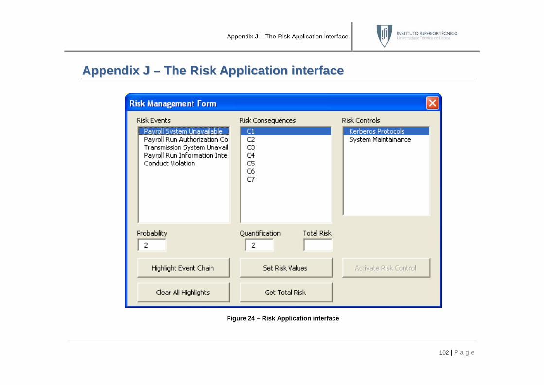
Appendix J – The Risk Application interface
102 | P a g e
AAppppeennddiixx JJ –– TThhee RRiisskk AAppppll iiccaatt iioonn iinntteerrffaaccee
Figure 24 – Risk Application interface

Appendix K – Muehlen’s example
103 | P a g e
AAppppeennddiixx KK –– MMuueehhlleenn’’ss eexxaammppllee
Figure 25 – Muehlen 's Payroll Process example in eEPC (see [24])

Appendix L – The BPMN example without Risk
104 | P a g e
AAppppeennddiixx LL –– TThhee BBPPMMNN eexxaammppllee wwii tthhoouutt RRiisskk
Figure 26 – Muehlen 's Payroll Process example in BPMN (without risks)
PayrollSupervisors
AccountingStaff
Member
Payroll Supervisor 2
Payroll Supervisor 1
Enter Payroll RunInformation
Transmit Payroll RunInformation to Bank
PayrollSystem Signed
Payroll RunAuthorization
SignedPayroll Run
Authorization
Payroll RunAuthorization
TransmissionSystem
Approve PayrollRun 2
Approve PayrollRun 1
Payroll RunInformation
Entered
Payroll RunNot Approved
Payroll RunInformationTransmitted
Payroll RunApproved
Payroll Date <3days from today

Appendix M – The BPMN example with Risk
105 | P a g e
AAppppeennddiixx MM –– TThhee BBPPMMNN eexxaammppllee wwii tthh RRiisskk
Figure 27 – Muehlen 's Payroll Process example in BPMN (with risks)
Risks
PayrollSupervisors
AccountingStaff
Member
Payroll Supervisor 2
Risk Events
Risk Controls
Payroll Supervisor 1
Enter Payroll RunInformation
Transmit Payroll RunInformation to BankPayroll
System
PayrollSystem
SignedPayroll RunAuthorization
SignedPayroll RunAuthorization
Payroll RunAuthorization
TransmissionSystem
Payroll RunAuthorization
Corrupted
KerberosProtocols
SystemMaintainance
TransmissionSystem
Unavailable
Payroll RunInformationIntercepted
ConductViolation
Payroll SystemUnavailable
Approve PayrollRun 2
Approve PayrollRun 1
Risk Control BRisk Control A
Risk Event ERisk Event CRisk Event A Risk Event B Risk Event D

Appendix N – Risk properties
106 | P a g e
AAppppeennddiixx NN –– RRiisskk pprrooppeerrtt iieess
Figure 28 – System Architect Risk Event, Control an d Consequence property screenshots

Appendix O – Risk reporting
107 | P a g e
AAppppeennddiixx OO –– RRiisskk rreeppoorrtt iinngg
Name Risk Stereotype Probability Event Types Risk Consequences Resource
Conduct Violation Risk Event 2 Human Resource C3 Definition:Participant:Payroll Supervisor 1
C4 Definition:Participant:Payroll Supervisor 2
Payroll Run Information Intercepted Risk Event 2 Information C6 Definition:Data Object:Signed Payroll Run
Authorization
Payroll Run Authorization Corrupted Risk Event 5 Information C2 Definition:Data Object:Payroll Run
Authorization
Payroll System Unavailable Risk Event 2 Technology C1 Definition:Data Object:Payroll System
C7
Transmission System Unavailable Risk Event 7 Technology C5 Definition:Data Object:Transmission System
Table 65 – Risk Event Reporting
Name Consequence Description Quantification Risk Event Resource Risk Control
C1 The payroll system fails and becomes unavailable. The
Enter Payroll Run Information activity is suspended
undeterminably.
2 Payroll System
Unavailable
Definition:Data Object:Payroll
System
System
Maintainance
C2 Corrupted data in mistakenly inserted in the Payroll Run
Authorization. Approval Payroll Run activity compromised.
2 Payroll RunAuthorization
Corrupted
Definition:Data Object:Payroll
Run Authorization
C3 Payroll Supervisors approve the payroll without realizing
the mistake.
3 Conduct Violation Definition: Participant:Payroll
Supervisor 1
C4 The transmission system fails and becomes unavailable.
The Transmit Payroll Run Information to Bank activity is
suspended undeterminably.
3 Conduct Violation Definition:Participant:Payroll
Supervisor 2
C5 The transmission system fails and becomes unavailable.
The Transmit Payroll Run Information to Bank activity is
suspended undeterminably.
1 Transmission System
Unavailable
Definition:Data
Object:Transmission System
System
Maintainance
C6 The signed payroll run transmission is intercepted. 4 Payroll Run Information
Intercepted
Definition:Data Object:Signed
Payroll Run Authorization
Kerberos
Protocols

Appendix O – Risk reporting
108 | P a g e
C7 The payroll system fails and becomes unavailable. The
Transmit Payroll Run Information to Bank activity is
suspended undeterminably.
1 Payroll System
Unavailable
Definition:Data Object:Payroll
System
System
Maintainance
Table 66 – Risk Consequence Reporting
Name Risk Stereotype
Probability
Reduction Control Types
Quantification
Reduction Risk Events Risk Consequences
Kerberos Protocols Risk Control 3 Mitigation 2 Payroll Run Information Intercepted C6
System Maintainance Risk Control 10 Avoidance 0 Payroll System Unavailable C1
Transmission System Unavailable C5
Payroll System Unavailable C7
Table 67 – Risk Control Reporting
Figure 29 – Risk Event Report in System Architect

Appendix P – The BPMN example with Risk event testing
109 | P a g e
AAppppeennddiixx PP –– TThhee BBPPMMNN eexxaammppllee wwii tthh RRiisskk eevveenntt tteesstt iinngg
Figure 30 – Highlight Event Chain macro applied on the case study
Risks
PayrollSupervisors
AccountingStaff
Member
Payroll Supervisor 2
Risk Events
Risk Controls
Payroll Supervisor 1
Enter Payroll RunInformation
Transmit Payroll RunInformation to BankPayroll
System
PayrollSystem
SignedPayroll Run
Authorization
SignedPayroll RunAuthorization
Payroll RunAuthorization
TransmissionSystem
Payroll SystemUnavailable
Payroll RunAuthorization
Corrupted
TransmissionSystem
Unavailable
Payroll RunInformationIntercepted
ConductViolation
KerberosProtocols
SystemMaintainance
Approve PayrollRun 2
Approve PayrollRun 1
Risk Control BRisk Control A
Risk Event ERisk Event CRisk Event A Risk Event B Risk Event D

Appendix Q – The BPMN example with Risk control testing
110 | P a g e
AAppppeennddiixx QQ –– TThhee BBPPMMNN eexxaammppllee wwii tthh RRiisskk ccoonnttrrooll tteesstt iinngg
Figure 31 – Activate Risk Control macro applied on the case study
Risks
PayrollSupervisors
AccountingStaff
Member
Payroll Supervisor 2
Risk Events
Risk Controls
Payroll Supervisor 1
Enter Payroll RunInformation
Transmit Payroll RunInformation to BankPayroll
System
PayrollSystem
SignedPayroll Run
Authorization
SignedPayroll Run
Authorization
Payroll RunAuthorization
TransmissionSystem
Payroll SystemUnavailable
Payroll RunAuthorization
Corrupted
TransmissionSystem
Unavailable
Payroll RunInformationIntercepted
ConductViolation
KerberosProtocols
SystemMaintainance
Approve PayrollRun 2
Approve PayrollRun 1
Risk Control BRisk Control A
Risk Event ERisk Event CRisk Event A Risk Event B Risk Event D

Appendix R – The BPMN extensions Class Diagram
111 | P a g e
AAppppeennddiixx RR –– TThhee BBPPMMNN eexxtteennssiioonnss CCllaassss DDiiaaggrraamm
Figure 32 – Class Diagram of the notational extensi ons for [33]