Embed Size (px)
Citation preview
66VOLTAR AO INÍCIO
CORROsãO e PROTeCçãO de MATeRIAIs2013, Jul/Ago/Set, Vol. 32, No 3, 66 - 95 - ISSN 2182-6587
CORROsãO de ARMAduRAs de CILINdROs de beTãO POR IMPedâNCIA eLeCTROquÍMICA
sTReNgTheNINg MeChANIsMs Of MATeRIALs fOR hIgh TeMPeRATuRe APPLICATION
eVALuATION Of CORROsION behAVIOuR Of ORgANIC COATed sTRuCTuRed sheeT MeTALs

67VOLTAR AO INÍCIO

68VOLTAR AO INÍCIO
CORROsãO e PROTeCçãO de MATeRIAIs 2013, jul/ago/set, vol. 32, nº 3
Ficha Técnica
directora: Teresa Cunha diamantino
directora Adjunta: Isabel figueira Vasques
Revisão: Maria Teresa Nogueira
Conselho Técnico-Científico: Alda simões (IsT) Carlos silva (ReN) elisabete Almeida Inês fonseca (fCuL) João Machado (CIN) Jorge Correia (fCuL) José gomes (Consultor) José Inácio Martins (feuP) José M. Antelo José Vieira (sIKA) Leonor Côrte-Real (hempel) Luís Rocha (uM) Manuela Cavaco (APT) Manuela salta (LNeC, I. P.) Mário g. s. ferreira (uA) Victor M. M. Lobo (uC) Zita Lourenço (Zetacorr)
Colaboradores Permanentes: César A. C. sequeira (IsT) Christopher M. A. brett (uC) fernando fragata (CePeL, bR) Paula Rodrigues (LNeC, I. P.) José Luís Nogueira (ARCP) Manuel Morcillo (CeNIM, es) Zehbour Panossian (IPT, bR)
Concepção Gráfica e PaginaçãoWhat Colour Is This? – design & graphic Artsinfo: [email protected]
editorLNeg – Laboratório Nacional de energia e geologia, I.P.estrada do Paço do Lumiar, nº 221649-038 LisboaTel. + 351 21 092 46 51/[email protected]
www.lneg.pt
depósito Legal: 28088/89
Capa: Pormenor de um barco naufragado na praia de Vila Nova de Milfontes, Maio 2013 (foto gentilmente cedida por Teresa Nogueira).
SUMÁRiO
cOMEnTÁRiO Maria Teresa NogueiraInvestigadora do LMR/LNEG
aRTiGOS - Corrosão de armadura de cilindros de betão confinados
por duas camadas de gfRP avaliada por impedância electroquímica.
B. Sena da Fonseca, A. S. Castela, M. G. S. Ferreira, R. G. Duarte e M. F. Montemor
- strengthening mechanisms of materials for high temperature application.
C. A. C. Sequeira e L. Amaral
- evaluation of corrosion behaviour of organic coated structured sheet metals.
E. Kornienko, R. Ossenbrink and V. Michailov
caSO REal dE cORROSãO- Incêndio na caldeira de um sistema de recuperação
de calor. J. I. Martins
inFORMaÇãO - Novidades- Regulamentação- Publicações em destaque- Notícias breves- Calendário- Instruções para os autores
se desejar receber esta publicação cómoda e gratuitamente no seu e-mail clique aqui e envie os seus dados.
CORROsãO e PROTeCçãO de MATeRIAIs

69VOLTAR AO INÍCIO
COMeNTáRIO Corros. Prot. Mater., Vol. 32, Nº 3 (2013)
Maria Teresa nogueira Investigadora do Laboratório de Materiais e Revestimentos do LNeg
Avaliação da produção científica
Na produção científica podem estar incluídos os artigos de publicações científicas periódicas, os livros ou capítulos técnico-científicos, as teses e monografias académicas (e.g. doutoramento, agregação) e as candida-turas à atribuição de prémios ou subsídios, bem como as candidaturas a projectos.
Na tentativa de tornar objectiva a avaliação da produção científica, há actualmente pressões de diferentes entidades para que a análise de tra-balhos técnico-científicos seja feita exclusivamente com base em parâ-metros quantitativos tais como o "factor de Impacto" (fI) das Revistas onde os trabalhos foram publicados. Veja-se, por exemplo, o Edital para um concurso para Professor Catedrático de uma universidade Portu-guesa, que diz explicitamente: “procurará o articulado que obriga a que a seriação dos candidatos seja feita por uma fórmula baseada nos dados da ISI Web of Knowledge”. O fI foi criado por Eugene Garfield, o fundador do Institute for Scientific Information (IsI), hoje parte da Thomson Reuters Corporation. desde 1972 que os fI são calculados anualmente para os periódicos indexados ao ISI, sendo depois publicados no Journal of Cita-tion Reports, também da Thomson Reuters.
há ainda a considerar que, das bases de dados mais usadas em avaliação de produção científica/bibliometria, para além da Web of Science, exis-tem outras duas, concretamente: l a scopus da elsevier (com início de actividade em 2004 e com o prin-
cipal objectivo de pesquisa por autor e assunto, incluindo títulos em acesso livre, páginas Web, livros e com mais conteúdos europeus e mais línguas para além do inglês) e
e competências do Sistema Científico e Tecnológico Nacional e ainda potenciar a valorização económica das empresas, com impacto na com-petitividade do sistema sócio-económico Nacional;l O resultado do trabalho de investigação deve cumprir ainda os se-
guintes critérios: ser credível (baseando-se esta credibilidade em crité-rios de avaliação reconhecidos, como é o caso da arbitragem científica), ser divulgado e estar acessível.Em nome da promoção e divulgação científica e tecnológica há que eliminar todas as práticas que descriminem negativamente as revistas técnico-científicas que demonstrem ter arbitragem científica mas que não tenham fI.
Dada a diversidade e especificidade de determinada área do conheci-mento, a qual importa preservar, e ainda devido ao facto do trabalho científico ser complexo e multidimensional, conclui-se, assim, que não há indicadores universais de avaliação. Como alternativas ou modelos complementares de avaliação, podem também referir-se vários tipos de índices ou indicadores, como por exemplo os existentes nesta re-vista, um contador de “visitas” ou a sua inclusão em bases de dados específicas como o Chemical Abstracts Service (American Chemical So-ciety), para além da plataforma da scielo para revistas com artigos em português.
A relevância dada por várias entidades nacionais e internacionais ao “Factor de Impacto” de uma Revista é, muitas vezes, injusta e desajusta-da, tanto para os autores que optam por publicar em revistas que ainda não tenham FI, como é o caso da Revista “Corrosão e Protecção de Ma-teriais”, mas ainda mais penalizadora para os editores de Revistas como esta, com arbitragem científica, que tanto se esforçam pela divulgação, qualidade e rigor dos trabalhos técnico-científicos desenvolvidos em Portugal. Esta Revista é o exemplo de uma publicação em área cientí-fica particular, disponibilizada integralmente na internet, com código de ética e com boas práticas na publicação. satisfaz ainda os critérios de avaliação qualitativa atrás expostos, sendo editada pelo Laboratório Nacional de energia e geologia, ao qual foi recentemente atribuído o Logotipo de Excelência de Recursos Humanos na Investigação (HRS4R - human Resources strategy for Researchers), no âmbito da assinatura da Carta europeia do Investigador.
“Nem tudo o que é importante pode ser quantificadoe nem tudo o que pode ser quantificado é importante"
Albert Einstein
l o google scholar Metrics (disponível desde 2012 mas com bastantes críticas, pois apresenta erros na identificação de autores, periódicos e dados bibliográficos e inclui também revistas sem arbitragem científica e sem carácter científico), tal como referido por Lopes, s. et al., 2012.
Por outro lado, existem outras ferramentas de avaliação, como é o caso dos indicadores bibliométricos, que podem ser divididos em indicado-res de qualidade científica (avaliação do conteúdo por pares), indicado-res de actividade científica (número e distribuição da produtividade dos autores) e indicadores de impacto científico (número de citações dos trabalhos e factor de impacto das revistas).É importante salientar as diferentes desvantagens da utilização de crité-rios exclusivamente quantitativos na avaliação da produção científica e que são a seguir referidas:l Tendem a promover/privilegiar mais o crescimento quantitativo do
que o incremento de qualidade dos trabalhos científicos; l dependem da dimensão da área do conhecimento, sendo as áreas
gerais mais lidas e citadas do que as áreas muito específicas; l Têm limitações, quer idiomáticas, quer geográficas, na inclusão de
periódicos em bases de dados como o Science Citation Index, com pre-domínio de conteúdos anglo-saxónicos, ausência de revistas de carác-ter regional e também com poucos conteúdos em acesso livre;l estimulam a autocitação e a citação cruzada entre autores conheci-
dos ou de entidades complementares;l há ainda a referir dois problemas fundamentais relacionados com
a métrica em ciência, nomeadamente que a quantidade não significa qualidade e que o impacto a curto prazo não implica importância a lon-go prazo.
A avaliação qualitativa da produção científica é, assim, essencial e deve ser rigorosa, independente e realizada por peritos, ou seja, personali-dades de reconhecido mérito, em número e composição suficientes de modo a garantir decisões justas e imparciais. A arbitragem científica é uma actividade à qual deve ser dada especial atenção e dignificada de modo a contribuir para o incremento de qualidade dos trabalhos cien-tíficos, promovendo críticas construtivas e salientando os pontos fortes e fracos dos manuscritos.A avaliação de trabalho científico deve também basear-se em critérios tais como os descritos de seguida: l Os autores devem ser avaliados pelo seu reconhecido mérito, ido-
neidade e produção científica, entre outros aspectos relevantes;l O trabalho deve possuir valor científico e carácter inovador, po-
dendo deste modo contribuir para a acumulação de conhecimentos

70VOLTAR AO INÍCIO
ARTIgO Corros. Prot. Mater., Vol. 32, Nº 3 (2013)
Resumoeste trabalho teve como objetivo o estudo de armaduras de cilindros de betão armado confinados com duas camadas de polímeros reforçados com fibras de vidro (GFRP). Provetes cilíndricos de betão armado com e sem gfRP foram imersos em solução de cloreto de sódio. O estado das armaduras foi avaliado por medições de potencial de circuito aberto e por impedância eletroquímica com sistemas a dois e três eletrodos. Os resultados demostraram que o confinamento de duas camadas de GFRP apresenta baixa permeabilidade e atua como barreira física à penetração de solução. Verificou-se que imperfeições na fase de aplicação do GFRP e sua degradação são de grande importância na eficiência da prevenção de corrosão.
Palavras-chave: gfRP, betão Armado, Corrosão, eIs
CORROsION eVALuATION bY eLeCTROCheMICAL IMPedANCe Of ReINfORCed CONCReTe CYLINdeRs CONfINed bY TWO LAYeRs Of gfRP
abstractThis work aims to study the steel reinforcement corrosion in reinforced concrete confined with two layers of glass fiber reinforced polymers (gfRP). Reinforced concrete cylinders with and without gfRP were immersed in a sodium chloride solution. The corrosion process of the steel rebars was followed by open potential measurements and electrochemical impedance in two and three electrodes systems. Results have shown that two gfRP layers have low permeability and act as an efficient physical barrier. It has been found that imperfections during the gfRP application and its degradation are of great importance in the efficiency of corrosion prevention.
Keywords: gfRP, Reinforced Concrete, Corrosion, eIs
CORROsãO de ARMAduRA de CILINdROs de beTãO CONfINAdOs POR duAs CAMAdAs de gfRP AVALIAdA POR IMPedâNCIA eLeCTROquÍMICA Artigo submetido em Maio de 2013 e aceite em setembro de 2013
B. Sena da Fonseca(1)(2), A. S. Castela(3), M. G. S. Ferreira(1)(4), R. G. Duarte(3) e M. F. Montemor(1)(*)
(1) ICeMs, Instituto superior Técnico, universidade Técnica de Lisboa, Av. Rovisco Pais, 1, 1049-001 Lisboa, Portugal(2) faculdade de Ciências e Tecnologia, universidade Nova de Lisboa, 2829-516 Caparica
(3) Instituto Politécnico de setúbal, esTbarreiro, 2839-001 barreiro, Portugal(4) CICeCO, departamento de engenharia de Materiais e Cerâmica, universidade de Aveiro, 3810-193 Aveiro
(*) A quem a correspondência deve ser dirigida, e-mail: [email protected]
1. inTROdUÇãOO desempenho e a durabilidade dos componentes constituintes das infraestruturas em betão armado constituem uma preocupação crescente na construção civil, tendo presente os critérios de sustentabilidade actualmente privilegiados. Por outro lado, a degradação introduzida nessas estruturas por fatores exógenos está na origem de dispendiosas intervenções de reparação e reforço de estruturas de betão armado.
A corrosão das armaduras de aço é reconhecida como o maior problema que afeta a integridade estrutural destas estruturas [1 - 4]. em pilares de pontes, garagens subterrâneas e em construções costeiras a presença de elementos agressivos como os cloretos potencia esta situação [3].
Apesar das armaduras de aço estarem protegidas contra a corrosão devido ao ambiente alcalino proporcionado pelo betão (pH≈13), a penetração de iões cloreto pode provocar a destruição do filme passivo o que inicia a atividade corrosiva [1 - 3, 5 - 7].
Os produtos originados por esta reação possuem volume muito superior ao do seu estado original o que gera forças de tensão no interior do betão [7, 8]. Como consequência, poderá ocorrer fissuração e desagregação [1, 6 - 8] que se acentuam com o tempo pois as armaduras ficam diretamente expostas. A diminuição da secção das armaduras e a perda de aderência ao betão são duas consequências negativas para o desempenho de toda a estrutura.
Os métodos convencionais de reparação ou substituição de estruturas de betão armado acarretam elevados custos e são um dos maiores desafios da engenharia civil [9].
Para aumentar a vida útil e reduzir os custos de manutenção e reparação, é fundamental a utilização de novos materiais de elevada durabilidade e que permitam novas soluções construtivas e nos últimos 20 anos, um grande número de estudos têm sido realizados pela comunidade científica. Comprovou-se que a utilização de compósitos reforçados por fibra (FRP) no reforço de vigas, lajes e pilares conduz a vantagens como o aumento considerável da
resistência mecânica e melhoria das características sísmicas da estrutura [10 - 16]. É também um material de fácil aplicação e com um reduzido impacto arquitetónico [14].
Assim, a aplicação deste tipo de compósitos é reconhecida em todo o mundo como uma tecnologia viável de reforço e reparação de infraestruturas e tem sido frequentemente empregue na reabilitação de diversas estruturas nos euA, Japão e europa [13] sendo uma das principais aplicações no confinamento de pilares de viadutos e pontes [10].
Existem diversos casos de reabilitação de estruturas com problemas de corrosão de armaduras em que foi utilizado fRP por questões económicas [17, 18]. No entanto, o principal objetivo tem sido o reforço estrutural, já que a presença de humidade em conjunto com cloretos e oxigénio no interior do betão torna a aplicação do FRP inconsequente na paragem da corrosão, sendo aconselhável a extração eletroquímica de cloretos (eCe) numa etapa prévia da reparação [19].
diversos ensaios laboratoriais têm sido efetuados para avaliar a aptidão dos fRP no abrandamento da corrosão das armaduras e as suas conclusões publicadas. devido ao elevado tempo necessário para avaliar a corrosão em condições semelhantes às reais, o procedimento habitual recorre a técnicas de corrosão acelerada, nomeadamente através da aplicação de uma corrente elétrica no sistema para acelerar o transporte dos iões agressivos através do betão [1, 3, 5, 8, 9], embora se saiba que esta técnica provoca mudanças na composição química, nas propriedades elétricas e na microestrutura do betão, o que influencia a resposta global do sistema e o afasta de um caso real [20].
de qualquer das formas, parece unânime a conclusão de que ocorre uma diminuição da taxa de corrosão em armaduras expostas em betão armado onde foi aplicado fRP. Note-se que o processo também depende de vários parâmetros como o tipo de resina e fibras, sua orientação e o número de camadas utilizadas [18].
em trabalho anterior [21] estudou-se por espectroscopia de impedância eletroquímica (eIs) o comportamento de armaduras
VOLTAR AO INÍCIO
70-74
ARTIgO Corros. Prot. Mater., Vol. 32, Nº 3 (2013)
71VOLTAR AO INÍCIO
expostas a betão revestido com uma camada de FRP de fibra de vidro (gfRP). Concluiu-se que o gfRP atua como uma barreira física à penetração de agentes corrosivos. Uma vez que é extremamente sensível a variações na fase de confinamento, não foi possível garantir este efeito em todos os provetes. Por outro lado, em contacto com agentes agressivos, o gfRP tende a degradar-se o que permite a lenta penetração destes agentes.
O presente artigo pretende contribuir para o conhecimento deste tipo de efeito, assim como para despistar eventuais erros atribuíveis em medições eIs a dois electrodos não inertes. O estudo foi efetuado em provetes cilíndricos de betão armado, quer não confinados, quer confinados por duas camadas de GFRP, a escala laboratorial. A aplicação do colete de fRP foi efetuada antes da contaminação, simulando a sua utilização no momento inicial da construção. Por medidas do potencial de circuito aberto (OCP) e espectroscopia de impedância eletroquímica (EIS) pretendeu-se avaliar em tempo real, a influência da aplicação de duas camadas gfRP na degradação da armadura.
2. METOdOlOGia ExPERiMEnTalforam construídos provetes cilíndricos de betão com uma relação água/cimento (a/c) igual a 0,50. As proporções da mistura em percentagem de massa foram as seguintes: 46,06% de brita com dimensões inferiores a 9,5 mm, devido às reduzidas dimensões dos provetes; 35,53% de areia; 12,28% de cimento Portland CeM I classe 42,5R e 6,14% de água.
Para simular a armadura utilizou-se em cada provete um varão de aço comum com 12 mm de diâmetro. uma vez que a contaminação não será acelerada por outros processos, optou-se por uma espessura de recobrimento dos varões de 15 mm, abaixo dos valores mínimos aconselhados e normalmente utilizados.
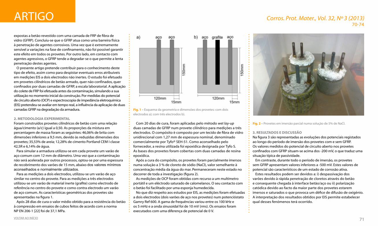
Para as medições a dois electrodos, utilizou-se um varão de aço similar no centro do provete. Para as medições a três electrodos utilizou-se um varão de material inerte (grafite) como electrodo de referência no centro do provete e como contra electrodo um varão de aço comum. As características geométricas dos provetes são apresentadas na figura 1.
Após 28 dias de cura o valor médio obtido para a resistência do betão à compressão em ensaios de cubos feitos de acordo com a norma NP eN 206-1 [22] foi de 37,1 MPa.
Fig. 1 – esquema da geometria e dimensões dos provetes: com dois
electrodos a); com três electrodos b).
Com 20 dias de cura, foram aplicadas pelo método wet lay-up duas camadas de gfRP num provete cilíndrico para medições a três electrodos. O compósito é composto por um tecido de fibra de vidro unidirecional com 1,27 mm de espessura nominal, denominado comercialmente por Tyfo® seh-51. Como aconselhado pelo fornecedor, a resina utilizada foi epoxídica designada por Tyfo S. As bases dos provetes foram cobertas com duas camadas de resina epoxídica.
Após a cura do compósito, os provetes foram parcialmente imersos numa solução a 3 % de cloreto de sódio (NaCl), valor semelhante à concentração média da água do mar. Permaneceram neste estado no decorrer de toda a investigação (figura 2).
As medições de OCP foram obtidas com recurso a um multímetro portátil e um eléctrodo saturado de calomelanos. O seu contacto com o betão foi facilitado por uma esponja humedecida.
No que diz respeito aos estudos por eIs, as medições foram efetuadas a dois electrodos (dois varões de aço nos provetes) num potencióstato gamry Ref 600. A gama de frequências variou entre os 100 khz e os 5 mhz e a onda sinusoidal foi de 10 mV (rms). Os ensaios foram executados com uma diferença de potencial de 0 V.
Fig. 2 – Provetes em imersão parcial numa solução de 5% de NaCl.
3. RESUlTadOS E diScUSSãONa figura 3 são representadas as evoluções dos potenciais registados ao longo do período de imersão dos provetes com e sem gfRP. Os valores medidos do potencial de circuito aberto nos provetes confinados com GFRP situam-se acima dos -200 mV, o que traduz uma situação típica de passividade.
em contraste, durante todo o período de imersão, os provetes sem gfRP apresentam valores inferiores a -500 mV. estes valores de potencial são característicos de um estado de corrosão ativa.
estes resultados podem ser devidos a: i) despassivação dos varões devido à rápida penetração de cloretos através do betão e consequente chegada à interface betão/aço ou ii) polarização catódica devido ao facto da maior parte dos provetes estarem imersos e saturados o que provoca um défice de difusão de oxigénio. A interpretação dos resultados obtidos por eIs permite estabelecer qual desses fenómenos terá ocorrido.
70-74

ARTIgO Corros. Prot. Mater., Vol. 32, Nº 3 (2013)
72VOLTAR AO INÍCIO
Fig. 3 – evolução do OCP dos provetes ao longo do tempo de imersão.
A evolução dos espectros de eIs com o tempo de imersão é apresentada na figura 4.
Os diagramas de bode evidenciam, para o caso dos provetes sem gfRP, ligeiras diferenças nos sistemas. embora com progressão semelhante, os resultados das medições a dois electrodos revelam, regra geral, resistências óhmicas superiores. Os valores para as altas frequências que estão associados às características do betão, mostram consideráveis diferenças entre provetes com e sem gfRP.
Nas frequências intermédias e baixas ocorreu uma diminuição ligeira do ângulo de fase ao longo do tempo para os provetes sem gfRP, sugerindo que o processo de corrosão se torna mais importante. Para os provetes com gfRP, o ângulo de fase apresenta-se superior e constante ao longo do tempo, o que revela um estado passivo dos varões de aço. Nestes provetes é também possível identificar uma constante de tempo adicional que corresponderá à presença de um filme protetor na superfície do aço, que protege a armadura, adiando o início das reações de corrosão.
Nas frequências baixas, é possível identificar fenómenos de difusão caracterizados pela distorção do patamar correspondente à resistência de transferência de carga.
Fig. 4 – diagramas de bode ao longo do tempo de imersão: a) 9 dias; b) 85 dias; c) 182 dias; d) 241 dias e e) 302 dias.
70-74

ARTIgO Corros. Prot. Mater., Vol. 32, Nº 3 (2013)
73VOLTAR AO INÍCIO
Fig. 6 – evolução da resistividade do betão.
uma vez que a resistividade é inversamente proporcional à condutividade e que a velocidade de corrosão do sistema é condicionada pela quantidade de eletrólito disponível para o transporte de cargas, através da resistividade pode-se obter alguma informação qualitativa acerca da corrosão. genericamente considera- -se que a corrosão é pouco provável para valores de resistividade superiores a 12000 Ω.cm, é provável entre 5000 e 12000 Ω.cm e para valores inferiores a 5000 Ω.cm a corrosão será muito provável [7].
Nos provetes sem gfRP, após três dias de imersão os valores variam entre os 800 e 1400 Ω.cm. Esta gama de valores permite afirmar que ocorreu uma rápida penetração de solução no betão e que os provetes estão saturados.
Com a evolução do tempo de imersão, a cura do betão prossegue através de processos de hidratação o que resulta num aumento progressivo da resistividade do betão. Existe, no entanto, uma tendência para valores mais estáveis de resistividade após 3 meses de imersão.
Para os provetes confinados com GFRP os valores obtidos durante os primeiros dias de imersão são várias vezes superiores. Apresentam uma resistividade de cerca de 12000 Ω.cm. A presença de GFRP tem o efeito de uma barreira física que retarda a absorção de solução e isto reflete-se numa maior resistência. Além disso, devido à maior taxa das reações de hidratação, o betão apresenta um aumento significativo de resistividade. Após 300 dias a resistividade sofreu um aumento
Para caracterizar os dois tipos de provetes, com e sem gfRP, e acompanhar a evolução dos fenómenos ocorridos ao longo do tempo, recorreu-se à utilização de circuitos equivalentes.
O circuito equivalente adotado para descrever o sistema dos provetes com GFRP (figura 5 b) caracteriza-se por: resistência do betão (R
b); constante de tempo que resulta de filmes passivos na superfície
do aço (C1 e R
1) e uma capacidade de dupla camada (C
dc).
No que respeita à modelação dos espectros correspondentes aos provetes sem aplicação de GFRP (figura 5 a), uma vez que se detetou um estado de corrosão ativa, o circuito utilizado foi ligeiramente alterado. foi adicionada uma resistência de transferência de carga (R
tc)
e um elemento para caracterizar fenómenos de difusão através da camada de óxidos (CPE1).
Fig. 5 – Circuitos equivalentes utilizados para simulação dos espectros obtidos
para os provetes de betão: com gfRP a); sem gfRP b).
Através dos valores obtidos por ajuste é possível acompanhar a evolução da resistividade do betão (figura 6), assim como os valores da resistência de transferência de carga.
A evolução da resistividade do betão é importante para uma melhor compreensão da influência do confinamento por GFRP na penetração da solução. Os valores de resistividade do betão foram obtidos através das frequências elevadas, a partir dos valores R
b. esta resistência foi
convertida em resistividade, tendo em conta a área do electrodo e a espessura do betão entre electrodos.
de 3 vezes face à inicial o que revela a conservação das propriedades durante este período de tempo.
silva (2007) [23], para o caso de uma solução salina, estimou um coeficiente de difusão para o GFRP de 1,55x106 mm2/s, valor várias vezes inferior ao de um betão comum. A proteção natural que o betão confere contra a corrosão e o reduzido coeficiente de difusão do GFRP formam uma ação conjunta e eficaz na prevenção da corrosão.
Por outro lado, são conhecidos os efeitos de soluções de NaCl na degradação das propriedades do gfRP. Os danos produzidos podem resultar de lixiviação das fibras e formação de micro-fissuras [24]. O enfraquecimento da matriz ocorre por plasticização e, embora este dano pareça ser reversível, a exposição constante provoca danos irreversíveis através de hidrólise [25, 26]. Além disso, a integridade estrutural e o desempenho do gfRP são fortemente dependentes da estabilidade da ligação fibra/matriz. A difusão de moléculas causa expansões volumétricas e provoca tensões diferenciais na interface fibra/matriz [27].
Devido à penetração de solução ocorrer apenas pelo exterior, seria previsível que a utilização de duas camadas quando comparadas com um confinamento com uma camada diminuísse a permeabilidade do confinamento e que este mantivesse as suas características barreira intactas durante um maior período de tempo. Contudo, Khoe et al. (2010) [28] afirma que laminados apenas com uma camada são menos permeáveis do que sistemas com duas camadas.
Alguns autores [21] referem que todos os provetes de betão confinados com uma camada de GFRP sofreram uma significante diminuição de resistividade nos primeiros 300 dias de contaminação. Isto indica que o gfRP perdeu o seu efeito barreira durante este período de tempo. este efeito revela-se mais sensível a pequenas variações e imperfeições inerentes à aplicação de gfRP por wet-lay up, do que à reduzida permeabilidade natural do material. Também a durabilidade do GFRP é um dos fatores principais na eficaz redução de penetração de cloretos e na redução da probabilidade de corrosão das armaduras.
Na tabela 1 apresentam-se alguns dos resultados experimentais obtidos através dos ajustes aos dados experimentais.
Após nove dias de imersão, os provetes com gfRP apresentam um comportamento tipicamente passivo com declives determinados no diagrama de log |Z| superiores a 0,8. Os provetes não confinados
70-74

ARTIgO Corros. Prot. Mater., Vol. 32, Nº 3 (2013)
74VOLTAR AO INÍCIO
Pela evolução da resistividade concluiu-se que os provetes confinados se mantiveram num estado seco e que os processos de hidratação prosseguiram a uma taxa elevada. Os varões mantiveram- -se num estado passivo durante os 300 dias de ensaio. O confinamento revelou reduzida permeabilidade à penetração de solução e atuou como uma barreira física. quando comparados com a utilização de uma camada, verificou-se que a utilização de duas camadas é mais eficaz na prevenção de penetração de cloretos.
Imperfeições na fase de aplicação de gfRP e a sua degradação por ataque através de uma solução salina são dois aspetos de grande importância na eficiência de redução da probabilidade de corrosão.
aGRadEciMEnTOSOs autores agradecem à fundação para a Ciência e Tecnologia por financiar o projeto DUST-PTDC/ECM/100538/2008 que suportou a presente investigação.
REFERÊnciaS[1] T. e. Maaddawy, A. Chahrourm and K. soudki, J. Compos. Constr., 10(2),
139 (2006).[2] M. f. Montemor, M. P. Cunha, M. g. ferreira and A. M. simões, Cement
Concrete Comp., 24(1), 45 (2002).[3] s. Masoud and K. soudki, Cement Concrete Comp., 28(10), 969 (2006).[4] J. Li, J. gong and L. Wang, Constr. Build. Mater., 23(7), 2653 (2009).[5] C. Lee, J. f. bonacci, M. d. A. Thomas, M. Maalej, s. Khajehpour, N. hearn,
s. Pantazopoulou and s. sheikh, Can. J. Civil Eng., 27, 941 (2000).[6] L. K. spainhour, I. A. Wootton and N. Yazdani (effect of Composite fiber
Wraps on Corrosion of Reinforced Concrete Columns in a simulated splash Zone), in Proceedings of the 3rd International Conference on Composites in the Infrastructure, June, san francisco, usA (2002).
[7] M. f. Montemor (estudo da deterioração por corrosão de estruturas de betão Armado). dissertação para a obtenção do grau de doutor, IsT, Lisboa (1995)
[8] s. gadve, A. Mukherjee and s. N. Malhotra, Constr. Build. Mater., 23(1), 153 (2009).
[9] I. A. Wootton, L. K. spainhou and N. Yazdani, J. Compos. Contr., 7(4), 339 (2003).
[10] M. Yaqub, and C. g. bailey, Compos. Struct., 93(3), 1103 (2011).[11] K. W. Neale, Progr. Struct. Eng. Mater., 2(2), 133 (2000).
apresentam declives inferiores e valores de Rtc
característicos de um estado de corrosão ativo.
Com o evoluir do tempo de imersão, os dois tipos de provetes sem gfRP apresentam valores de R
tc semelhantes e com uma velocidade de
corrosão ligeiramente variável ao longo do tempo.Esta diferença poderá ser explicada pela variação de temperatura e
humidade no ambiente ao longo das estações do ano, o que provocou diferentes comportamentos na absorção de água por capilaridade na parte emersa dos provetes.
Através dos declives é possível constatar que o confinamento provocou uma manutenção do estado passivo, com declives sempre superiores a 0,8 até ao final dos ensaios.
Tabela 1 – evolução da resistência de polarização obtida para os diversos tipos
de provetes.
4. cOnclUSõESOs provetes sem gfRP sofreram uma rápida saturação e por este motivo os varões de aço revelaram-se ativos numa fase precoce da investigação. Com o desenvolvimento dos ensaios esta corrosão intensificou-se.
[12] h. Toutanji, L. s. Matthys and K. Audenaert, (behaviour of large-scale columns confined with FRP composites), in Proceedings of the 2nd International Conference on FRP Composites in Civil Engineering- CICE, Adelaide, Australia (2004).
[13] h. V. s. gangaRao, N. Taly and P. V. Vijay (Reinforced Concrete design with fRP Composites), CRC Press (2007).
[14] Y. A. Al-Salloum (Experimental and Analytical Investigation of Compressive Strength of FRP-Confined Concrete), Final Report, King saud university, Kingdom of saudi Arabia (2007).
[15] A. Parvin, W. Wang, Compos. Struct., 58(4), 539 (2002).[16] R. benzaid, N. e. Chikh and h. Mesbah, J. Civ. Eng. Manag., 14(2), 115
(2008).[17] R. sen, Progr. Struct. Eng. Mater., 5(2), 99 (2003).[18] C. Khoe, R. sen and V. R. bhethanabotla, J. Compos. Constr., 15(4), 513
(2011).[19] M. Chauvin, C. shield, C. french and W. smyrl (evaluation of
Electrochemical Chloride Extraction (ECE) and Fiber Reinforced Polymer (fRP) Wrap Technology), final Report, university of Minnesota, Minnesota, usA (2000).
[20] d. A. Koleva et al., Cement. Concrete Comp., 30(8), 731 (2000).[21] b. sena da fonseca, A. s. Castela, M. g. s. ferreira, R. g. duarte, M. A.
g. silva and M. f. Montemor (Assessment of the effect of gfRP on the corrosion of steel reinforcement in confined RC by EIS), in Proceedings of 10th Symposium on Electrochemical Methods in Corrosion Research, Nov., Maragogi, brasil (2012).
[22] NP EN 206-1:2005. (Betão. Parte 1: Especificação, desempenho, produção e conformidade), IPq, Caparica (2005).
[23] M. A. g. silva, Compos. Struct., 79(1), 97 (2007).[24] A. S. Maxwell, W. R. Broughton, G. Dean and G. D. Sims (Review of
accelerated ageing methods and lifetime prediction techniques for polymeric materials), NPL Report-dePC MPR 016 (2005).
[25] s. Popineau, C. Rondeau-Mouro et al., Polymer, 46(24), 10733 (2005).[26] d. dunn (update on engineering and structural Adhesives), smithers
Rapra Technology (2010).[27] P. Vaddadi, T. Nakamura et al., Compos. Part A: Appl. S., 34(8), 719 (2003).[28] C. Khoe, R. sen and V. bhethanabotla, J. Compos. Constr., 15(4), 513
(2011).
70-74

75VOLTAR AO INÍCIO
ARTIgO Corros. Prot. Mater., Vol. 32, Nº 3 (2013)
sTReNgTheNINg MeChANIsMs Of MATeRIALs fOR hIgh TeMPeRATuRe APPLICATIONArtigo submetido em Abril de 2013 e aceite em Agosto de 2013
C. A. C. Sequeira(1)(*) and L. Amaral(1)
(1) Materials electrochemistry group, ICeMs, Instituto superior Técnico, Technical university of Lisbon, Av. Rovisco Pais, Nº 1, 1049-001 Lisbon
(*) Correspondig author, e-mail: [email protected]
abstractMetallic materials relevant for high temperature application include the nickel and cobalt base alloys and, to some extent, the titanium alloys and steels. In this paper, the mechanisms by which these alloys are strengthened and, more specifically, the strength achievements in these basic structural materials are discussed.
Keywords: strengthening Mechanisms, Titanium Alloys, steels, Nickel-iron Alloys, Nickel superalloys, Cobalt superalloys
MeCANIsMOs de eNduReCIMeNTO dOs MATeRIAIs PARA APLICAçÕes A ALTAs TeMPeRATuRAs
ResumoOs materiais metálicos para aplicações em sistemas que operam a altas temperaturas incluem ligas de níquel e de cobalto, bem como ligas de titânio e os aços. Neste artigo discutem-se os mecanismos de endurecimento desses materiais e, mais concretamente, analisam-se os procedimentos que conduzem a esse estado.
Palavras-chave: Mecanismos de endurecimento, Ligas de Titânio, Aços, Ligas de Níquel-ferro, superligas de Níquel, superligas de Cobalto
1. inTROdUcTiOnA significant number of industrial processes take place in very aggressive environments. Industrial components are often subjected to extreme conditions, which induce erosion and impact damage. Some examples of such conditions are high temperature, increased temperature gradients, high pressure, large stresses, or the presence of oxidizing and corroding atmospheres, as well as internally created or externally ingested particulate material. Fig. 1 illustrates several high temperature processes, showing the range of temperatures and required lives for the respective components.
Fig. 1 - high-temperature processes with component temperatures and
required lives [1].
Machines like aircraft gas turbine engines, steam turbines, industrial gas turbines, or processes such as coal conversion, petroleum refining, and nuclear power generation clearly involve the generation of large amounts of heat and the associated high component temperature. In the case of jet engines, fuel is mixed with highly compressed air and the mixture ignited. The turbine is rotated as a result of the air expansion due to the heat generated. On the other hand, the turbine forces the compressor to rotate, leading to the compression
of the incoming air, while the existing exhaust gas creates thrust for propulsion. In modern gas turbine engines, the gas temperature may well exceed 1650 ºC in the turbine section, with cooled parts reaching temperatures as high as 1200 ºC. In coal gasifiers, coal is converted into usable gas by reacting with steam at high temperatures. In this case, process temperatures may be as high as 1650 ºC with component temperatures reaching 1090 ºC. Regarding the process of petroleum refining, crude petroleum is catalytically cracked at high temperatures and fractioned into usable petroleum products such as liquid petroleum gas, gasoline, kerosene, diesel, heavy oils, plastics, asphalt and coke. In nuclear power plants, the controlled fission of fuel elements, such as uranium and thorium, generates heat used to produce steam, which is by its turn fed to turbines to generate electrical power.
All the mentioned processes involve high temperatures and therefore require construction materials with high-temperature capability under load to meet performance and durability requirements. during operation, in addition to fatigue and creep damage of structurally loaded components, the materials undergo oxidation, corrosion, and erosive wear. In fig. 2, typical temperatures of some industrial processes are compared with the melting points of some basic structural materials.
The variation with the temperature of the strength ranges of a few potential materials of construction for high-temperature processes is shown in fig. 3 [3]. several properties of many of these engineering materials, such as tensile, creep, and fatigue strength, are generally optimized for maximum load-carrying capability but less attention is paid to the environmental resistance. For example, turbine blades for jet engines are made of precipitation-strengthened nickel base superalloys, consisting in gamma prime (γ ’) phase precipitates in a gamma (γ) phase matrix. Aluminum is one of the constituents of the alloys, which participates in the formation of strengthening precipitates and provides for oxidation resistance. The aluminum content is kept at a level below 6 % in order to maximize creep
75-81

ARTIgO Corros. Prot. Mater., Vol. 32, Nº 3 (2013)
76VOLTAR AO INÍCIO
designers, to ensure the safe use of a construction part, even in the case that a sudden force of larger magnitude appeared during service. for that purpose, various strengthening mechanisms are usually employed, as well as surface treatments to increase the protection from the environment. strengthening generally involve dislocation generation, dislocation movement and the interactions of dislocations with each other or with other entities that might hinder their free motion. A summary of metals strengthening processes is presented in Table 1.
solid solution strengthening and precipitation hardening are effective mechanisms at high temperatures and, therefore, are used in strengthening high-temperature alloys. grain-size control is often used in conjunction with these mechanisms. By its turn, oxide dispersion strengthening (Ods) is sparsely used in some cases for moderate-temperature applications. The remaining mechanisms, martensitic transformation and work hardening, are not effective at temperatures of interest, being used only for low temperature applications.
75-81
Fig. 3 - Temperature capabilities of classes of materials (adapted from ref. [3]).
Fig. 4 - Temperature capabilities of several classes of alloys (adapted from ref. [2]).
Fig. 2 - Comparison between typical temperatures of some industrial processes
and the melting points of some basic structural materials [2].
strength, although higher aluminum content increases high-temperature oxidation resistance. If such bare alloys are exposed to the environment of high-pressure turbine of modern gas turbine engines, they will degrade fast by several processes including oxidation [4], high-temperature corrosion [5], and heat damage [6].
despite the fact that non-metallic materials such as monolithic ceramics and ceramic composites are becoming increasingly important in some of the above mentioned industrial processes, the demand for materials for those applications is met predominantly by metallic alloys. Properties such as high melting point, strength (tensile strength, creep strength, fatigue strength), ductility and toughness, and low density wherever possible, are the reason for the attractiveness of these alloys. however, the environmental resistance of the metallic alloys is rarely adequate.
four groups of alloys support the bulk of the demand in industrial processes. These groups are based on the metals aluminum, titanium,
iron, and nickel and cobalt. The dependence on the temperature of the range of density-corrected strengths of these classes of alloys is schematically depicted in fig. 4. It is clear that aluminum, with its low melting point of 660 ºC and its commercially available alloys with temperature capability limited to about 150 ºC, is not adequate for high-temperature applications. The only alloys relevant to such high-temperature applications include the nickel and cobalt based alloys and, to some extent, the titanium alloys and steels. The mechanisms by which these alloys are strengthened and, more specifically, the strength achievements in the basic structural high-temperature materials are discussed in this paper.
2. STREnGThEninG MEchaniSMS Pure metals are weak and usually have poor environmental resistance. The strengthening of materials is therefore of great importance for engineering applications. Construction parts must be designed not only to endure the anticipated forces (which materials are expected to withstand during service), but also any sudden, short-duration forces that, if not considered, might cause catastrophic failure. Liberal safety factors are generally adopted by

ARTIgO Corros. Prot. Mater., Vol. 32, Nº 3 (2013)
77VOLTAR AO INÍCIO
In addition to the substitutional solid solution in which solute atoms randomly replace solvent atoms, the solute atoms may also occupy interstitial sites in the solvent (Fig. 5 (b)). For example, carbon, which is a small atom, forms an interstitial solid solution with iron. The stress fields originated by the interstitial atoms also interfere with dislocation motion, thus influencing strength.
In the case of precipitation hardening, the solute atoms promote the formation of a fine and uniformly dispersed second phase. To achieve this condition, the solvent metal needs to form a supersaturated solid solution at high temperature. On cooling, the solute atoms are rejected from solution in the form of fine precipitates, due to the decrease of solubility. These precipitates then impede dislocation motion, with the strength achieved by this process being controlled by the size, strength, “coherence” and volume fraction of the precipitates. These parameters may be controlled through appropriate heat treatment of the alloys.
following this brief discussion, more detailed aspects concerning strengthening in the metallic materials for high temperature applications are analysed hereafter.
3. STREnGTh achiEVEMEnT in hiGh TEMPERaTURE allOYS 3.1 Titanium alloysTitanium and its alloys present very interesting structural properties [7]. The metal allies a high melting point of 1668 ºC and excellent corrosion resistance to a low density, 4.54 g/cm3 (about 60 % of that of steel and nickel and cobalt base superalloys). Titanium exhibits a hexagonal close packed (hcp) structure called a which transforms on heating to above 883 ºC into a body-centered cubic (bcc) structure b. The material, on a density-corrected basis, forms some of the strongest alloys available. Titanium alloys are extensively used in gas turbine engines as fan blades, compressor blades and vanes, disks, and cases, which is possible due to their high strength and low density. On the other hand, their susceptibility to interstitial formation during processing or application above 600 ºC, stabilizing the a phase, constitutes the major limitation for their use. This occurs by the spontaneous capturing of oxygen (as well as carbon and nitrogen). The a phase forms a brittle skin, known as the “a case”, which debits the structural properties of the alloys. Prior to any processing, the a case, therefore, must be chemically or mechanically removed.
Table 1 - strengthening mechanisms for metals.
Mechanisms Effective temperature
Solid-solution strengthening High temperature
Precipitation (or age) hardening High temperature
Grain size control Moderate temperature
Oxide dispersion strengthening (ODS) Moderate temperature
Martensitic transformation strengthening For specific metals at low temperature
Work hardening Low temperature
solid solution strengthening and precipitation hardening mechanisms involve hindering the movement of dislocations in the metallic structure. In a solid solution, appropriate alloying elements (the solute) are dissolved in a metal (the solvent). The solute atoms randomly substitute for the solvent atoms (fig. 5 (a)) without altering the phase, i.e., the crystal structure. depending on whether the substituting atom is larger or smaller than the solvent atom, compressive or tensile stresses, respectively, are generated in the vicinity of the solute atoms. The motion of the dislocations is then impeded by the presence of stress fields. The size differences between the solvent and the solute atoms and the volume fraction of the solute are determinant in the effectiveness of the strengthening. for this mechanism to be effective, the solute atoms must be reasonably soluble in the solvent metal, and the atomic size difference must be significant.
Fig. 5 - schematic of solid solution (a) substitutional (Al dissolved in Ni), (b)
interstitial (C dissolved in fe).
depending on the predominant phases, three families of titanium alloys may be considered: the a alloys, the a-b alloys, and the b alloys. In the a alloys, the a phase is stabilized by the addition of Al, which raises the b transus (the temperature boundary between the single-phase and two-phase regions, fig. 6 (a)). by their turn, the b alloys contain elements such as V, Nb, Mo, Cr, W, fe, Co, and si, which stabilize the b phase by lowering the b transus (fig. 6 (b)).
Fig. 6 - schematic of (a) a and (b) b alloy stabilization.
both phases are present in the case of the a-b alloys. some elements, such as Zr, sn, and hf, are neutral in the way that they do not stabilize either of the phases but contribute to property improvement. The increased strength in a alloys originates from solid solution strengthening due to Al and sn. every 1 % Al addition increases strength by about 8 ksi (55 MPa), while every 1 % addition of sn leads to an increase of 4 ksi (28 MPa). The a alloys are insensitive to heat treatment mainly due to the lack of second phases. On the other hand, the b alloys always contain small amounts of the a phase, which size and distribution may be controlled by a combination of thermal and mechanical treatments. This second phase precipitate is responsible for the improved strength. Nevertheless, the most useful titanium alloys are the a-b alloys, consisting of both a and b phases. In these alloys, heat treatments are beneficially used to control both solid solution strengthening and precipitate hardening.
75-81

ARTIgO Corros. Prot. Mater., Vol. 32, Nº 3 (2013)
78VOLTAR AO INÍCIO
Table 2 presents some of the commercially available titanium alloys and figure 7 depicts the creep strength of several Ti alloys as a function of the temperature. Considering the presented data, it is clear that the maximum use temperature of these titanium alloys is limited to 593 ºC.
Fig. 7 - Creep strength (0.1 % creep in 150 hrs) of selected titanium alloys as a
function of temperature [7].
Table 2 - Examples of commercially available titanium alloys.
AlloyYear of
introductionPhase
compositionMaximum use
temperature
Ti-6Al-4V 1954 ab 315 ºC
Ti-6Al-2Sn-4Zr-2Mo 1967 ab 510 ºC
Ti-6Al-2Sn-4Zr-2Mo-Si 1974 ab 565 ºC
Ti-5.5Al-4Sn-4Zr-0.3Mo-1Nb-0.5Si
1984 Near a 593 ºC
When titanium alloys are exposed to an oxygen-containing atmosphere at elevated temperatures, they not only dissolve oxygen and form a case but also oxidize, producing a titania (TiO
2) scale. unlike
alumina on many aluminum-containing alloys, titania is non-protective against continued oxidation, once that oxygen easily diffuses through it. To protect titanium alloys against oxidation at elevated temperatures, several coating systems have been investigated, such as platinum aluminides [8], magnetron sputtered Ti-Al [9], and Ti-Al-Cr [10].
3.2 steelsDespite their complexity, steels are among the most versatile and widely used structural materials [11]. On a density-corrected basis, as shown in fig. 4, the strengths of steels are competitive with nickel based superalloys at lower temperatures, with the advantage of being much more cost-effective. At higher temperatures, however, their strengths fall off below those of superalloys.
The structure of steels is based on the iron-carbon phase diagram depicted in fig. 8. due to the non-equilibrium cementite (fe
3C)
as a terminal phase, this is not a true equilibrium phase diagram; nevertheless, the diagram faithfully explains the microstructure and phase behaviour for the range of practical thermal exposure. Depending on the carbon content, steels are classified into low-carbon (<0.25 wt % C), medium-carbon (0.25 to 0.60 wt % C), and high-carbon (> 0.60 wt % C) steels. In order to widen the range of structural and physical properties, other alloying constituents besides carbon are also added to steels. In this way, each of the classes may contain additional alloying elements such as Cr, Mo, Ni, V, Nb, Ti and Al to form the so-called alloy steels. At room temperature, pure iron has a bcc structure called a iron or “ferrite” (Fig. 8) which converts to an fcc (face - centered cubic) γ phase called “austenite” above 911.5 ºC. With increasing temperature, before melting at 1538 ºC, austenite changes to a bcc phase called “d ferrite” at 1396 ºC. As shown in the phase diagram of Fig. 8, the sizes of the various phase fields vary with the carbon content.
A combination of mechanisms is used to strength steels. Among them are solid solution strengthening by interstitial elements such as carbon and nitrogen, substitutional solid solution, either in the a of the γ phase, precipitation hardening from carbides of Nb and V,
grain size control, and processing-induced texture of grains by, for example, rolling. Moreover, different phases may be stabilized by different alloying elements. The degree of solid-solution strengthening by substitution is controlled by expanding (with the addition of C, N, Cu, and Zn), contracting (by the addition of Ta, Nb, and Zr), opening (with the addition of Ni, Mn, Co, Ru, Rh, Pd, Pt, etc.), or closing (as in the case of the addition of si, Al, be, and P) the γ phase field of the phase diagram in fig. 8.
The austenite phase can dissolve as much as 2.11 wt % (~10 at %) carbon in a solid solution. If this phase is quenched very fast to a temperature in the vicinity of room temperature, instead of changing to ferrite and cementite as predicted by the phase diagram in fig. 8, it transforms into a phase called “martensite” supersaturated with
75-81
Fig. 8 - The iron-iron carbide metastable phase diagram [12].

ARTIgO Corros. Prot. Mater., Vol. 32, Nº 3 (2013)
79VOLTAR AO INÍCIO
carbon. The crystal structure is then distorted to body-centered tetragonal (bct) by the high carbon content. The unique feature of this phase transition is that it does not involve diffusion of atoms, but shear or local displacive transformation at rates close to the velocity of sound in the alloy. The maximum temperature below which martensitic transformation occurs is known as the martensite start temperature, M
s. The presence of martensite grains, which are hard
and brittle and show plate or needle-like morphology, significantly increases strength.
Time-temperature-transformation (TTT) diagrams [11] have been developed in order to design the right heat treatment regimens to achieve the optimum combination of microstructure, strength, and ductility of steels. The following list includes some of the commercially available steels:
High Strength Low Alloy Steel (HSLA): These are low carbon (0.03 to 0.15 wt % C) steels which derive their strengthening from a solid solution (C, Mn, si), precipitation hardening (carbides of Nb, Ti, and V), grain size control stabilized by grain boundary carbides and processing-induced texture. These materials typically show tensile strength and failure strains of 700 MPa (~100 ksi) and 12 to 18 %, respectively.
Bainite Steel: These steels consist in a strained ferrite matrix with a fine dispersion of cementite and are produced by an isothermal heat treatment of low carbon (<0.05 wt % C) steels according to a TTT diagram between 250 ºC and 550 ºC. bainite steels achieve tensile strength of 600-1200 MPa (around 87-174 ksi) and failure strains of 15-20 %.
Dual-Phase Steels: These are low carbon steels (0.1 to 0.2 wt % C) which contain two phases consisting of a fine dispersion of 10 to 20 vol % martensite in a ferrite matrix. This microstructure and phase contents are obtained by heating the material to the a+γ phase field (fig. 8) to form 10 to 20 vol % austenite which is then converted to martensite by rapid quenching. This method leads to steels with moderate to high tensile strength and high ductility.
Transformation Induced Plasticity Steels (TRIP): In this case, austenite (γ phase) is retained at room temperature by fast quenching, which is then mechanically deformed during processing. under load, the austenite phase transforms to martensite, leading to the strengthening of the steel, and to tensile strengths in the range of
600 to 1300 MPa (approximately 87 to 189 ksi), as well as failure strains as high as 25-40 %.
It should be said that the temperature capability of steels in stressed applications is controlled not only by strength but also by the environmental resistance and is generally limited to 650 ºC.
3.3 Nickel-iron alloysNickel-iron alloys usually contain 15 to 60 % iron and 25 to 60 % nickel [13]. This class of alloys has the fcc structure of γ austenite as a matrix strengthened by precipitates, as well as solid solution and grain boundary strengthening. Ni-Fe alloys are less expensive than Ni and Co base superalloys, and may be classified into five groups, as follows:
Group 1: The first group is relatively Fe-rich with 25 to 35 % Ni and less than 2 % Ti. The strengthening phase consists in coherent fcc γ ’ (called gamma prime) precipitates. Commercial alloys in this group include Tinidur, V-57, and A-286, which use temperature is limited to 650 ºC.
Group 2: Alloys in group 2 are rich in Ni (> 40 %) with increased contribution from a solid solution, leading to higher strengths than those of the iron-rich group. Inco X-750 and Inco 901 are examples of commercial alloys of this group.
Group 3: In this group, Ni-rich alloys owe their strength to coherent bct γ ” (called gamma double prime) precipitates. Inco 706 and 718 are commercial alloys representative of this group. The latter is one of the most used alloys of this class. The temperature capability of these alloys ranges from cryogenic to 650 ºC.
Group 4: These are Fe-rich Fe-Ni-Co alloys with low thermal expansion achieved through removal of Cr and Mo, which stabilize ferrite in the structure. Coherent fcc γ ’ precipitates are primarily responsible for the strength of this group of alloys. Commercial members of this class are Inco 903 and 909. The temperature capability of these alloys is limited to 650 ºC, and the elimination of Cr makes them more susceptible to oxidation and corrosion.
Group 5: This group of Ni-rich alloys has a particularity that is the absence of coherent precipitates. some of the alloys of this group derive their strength from precipitates of carbides, nitrides, and carbonitrides. Other alloys, such as hastelloy X and N-155, are solid-solution strengthened. for non-stressed applications, the latter may be used at temperatures limited to 1093 ºC.
3.4 Nickel and cobalt base superalloysThe name “superalloys” derives from the fact that this unique class of complex alloys based on Ni and Co exhibit extraordinarily high strength, which is also maintained across a wide elevated temperature range. Indeed, some of these alloys are used in load-bearing applications at temperatures exceeding 80 % of their melting point! Ni and Co are attractive metals because of their high melting point and crystal structures amenable to extensive alloying. Ni exhibits an fcc crystal structure, whereas Co is hexagonal close packed (hcp) at room temperature. Alloying elements are generally added in order to stabilize Co in the fcc form.
As depicted in fig. 9, a number of strengthening mechanisms are used to produce practical alloys with Ni and Co [14-16], including:
1. Strengthening of the austenitic γ phase by solid solution: The matrix of the alloys consists in the γ phase, which dissolves several metallic elements , such as Cr, Co, fe, Mo, Ta, W or Re (in Ni base alloys) and Ni, Cr, Mo, W, Nb, Ta (in Co base alloys), randomly replacing the matrix atoms (Fig. 5 (a)). Due to size differences relatively to the matrix, the substituting solute atoms originate stress fields that impede dislocation motion, by interacting with the stress fields of dislocations, and therefore increase strength. This mechanism operates both in Ni and Co base superalloys.
2. Precipitates of various carbides within the grains and at the grain boundaries: Carbon, which is invariably present in the matrix, forms carbides with some of the alloying elements during processing and heat treatment. In Ni base alloys, MC type carbide is formed with Ti, Ta, W, Mo, hf, Nb, whereas Cr, W and Mo lead to the formation of M
23C
6 type carbide; in Co base alloys, MC type carbide forms
with Ti and M23
C6 type carbide with Cr. Carbides within grains
impede dislocation motion, thereby increasing strength. On the other hand, grain boundary carbides pin boundary movement, hindering grain growth and also impeding grain boundary sliding. The carbides together with the solid solution provide the primary mechanism for strengthening of Co base superalloys. In the case of Ni based superalloys, these mechanisms are secondary to γ ’ and γ ” precipitation strengthening.
3. Coherent fcc γ ’ and bct γ ” precipitates: The primary strengthening mechanism of Ni base superalloys is provided by precipitates of the ordered intermetallic compound of composition Ni
3Al, known as
75-81

ARTIgO Corros. Prot. Mater., Vol. 32, Nº 3 (2013)
80VOLTAR AO INÍCIO
gamma prime, γ ’, with additional strengthening being achieved from solid solution and carbide precipitates. The Ni sites in the γ crystal structure may also contain Co, Cr and Mo, while the Al sites may contain Ti and Nb. The unique characteristic of the γ ’ structure is that it is coherent with the γ matrix. The matrix-precipitate interface for coherent and incoherent precipitates is schematically compared in fig 10. because coherent interfaces have low energy, the coherent precipitates have little driving force for growth in size. This is the reason for the strength retention of γ ’-strengthened superalloys over a wide high-temperature range. These fine and hard precipitates impede dislocation motion, resulting in a great increase in strength. figure 11 shows cuboidal γ ’ precipitates in a γ matrix [17].
Fig. 9 - Microstructure evolution of Ni base alloy and Cr content change [15].
Fig. 10 - Schematic of (a) a coherent precipitate with large strain fields
indicated by distortion of the lattice, (b) incoherent precipitate.
Fig. 11 - electron micrograph showing γ ’ precipitates (size 0.35 to 0.6 mm) in a
γ matrix [17].
The size and volume fraction of γ ’ precipitates are critical parameters regarding creep and fatigue strength of the alloys. The later is controlled by the Al+Ti content and ranges from 0.2 for wrought fe-Ni superalloys to above 0.5 in Ni base superalloys. The size of the γ ’ precipitates ranges from 0.2 to 0.6 mm, with small precipitates having spherical morphology and larger sizes tending to be cuboidal.
In some superalloys containing fe, such as Inco 718, the presence of γ ” (a bct structured phase with composition Ni
3Nb) is the predominant
strengthening mechanism. The γ ” phase is coherent with the γ matrix and provides high strengths in the low to moderate temperature regime. However, above 65 ºC, strength significantly drops, as a result of the decomposition of γ ” to either γ ’ or d.
fig. 12 presents the range of creep rupture strengths of superalloys strengthened by several of the mechanisms discussed above. Ni base superalloys in polycrystalline form are not acceptable for some creep-strength-critical applications, such as rotating turbine blades in modern gas turbine engines, because they tend to fail at grain boundaries oriented transversely to the centrifugal force of rotation, which is along the blade axis. These blades are fabricated by casting, which consists in melting of appropriate alloys in a furnace and pouring the melt into a ceramic shell. The creep properties of the alloys can be considerably improved by promoting columnar grains oriented
75-81
parallel to the blade axis that eliminates undesired transverse grain boundaries. These microstructures are achieved through “directional solidification”, which consists in a modification of the casting process so that heat is removed from the melt by slowly pulling the ceramic shell from the furnace. further increases in creep properties have been achieved by eliminating grain boundaries altogether in single-crystal superalloys, which are obtained by using a grain selector or appropriate seeds in the casting process. Polycrystalline, columnar, and single-crystal structured turbine blades developed by Pratt & Whitney are compared in figure 13.
Fig. 12 - superalloy creep rupture strengths as function of temperature [16].

ARTIgO Corros. Prot. Mater., Vol. 32, Nº 3 (2013)
81VOLTAR AO INÍCIO
Fig. 13 - Turbine blades made of nickel base alloys with various grain structures
[17].
single-crystalline Ni-based superalloys with a high fraction (over 50 %) of γ ’ phase (Ni
3Al) indeed exhibit a combination of excellent
strength, creep properties and fatigue resistance at high temperatures, being currently used as blades in gas turbines and aircraft engines [18]. As mentioned, the microstructure of these alloys consists of sub-micrometer size cubical γ ’ precipitates in a matrix of γ phase, an fcc super-saturated Ni solid solution. The size and volume fraction of the γ ’ phase dictate the width of the γ channels, which can be in the nanometer range. Other microstructural features that may be present in Ni-based superalloy single-crystals include low angle boundaries, casting defects such as pores, and γ/γ ’ eutectic pools due to incomplete solutionizing of the as-cast structure prior to the aging process. hot isostatic pressing (hIP) was shown to be helpful in the closure of porosity and elimination of the eutectic pools, contributing for the increased strength of these single-crystalline Ni-based superalloys [19].
4. cOnclUSiOnS The development of structural alloys as discussed in this article has generally the main goal of achieving high strength, ductility, and producibility. however, obtaining materials that combine these properties with environmental resistance toward oxidation and high-temperature corrosion is not an easy task. As an example, increased Al and Cr contents improve oxidation and corrosion resistance of the resulting alloys, but beyond a certain level, these elements reduce creep strength. The separation of the two functions is one approach that is generally used in order to combine both strength and resistance to the environmental degradation. The method consists in protecting a substrate alloy, which provides the load capability, by the application of thin coatings with adequate Al and Cr, achieving the desired oxidation and corrosion resistance. The thickness of the coating is adjusted in a way that it does not carry any significant load.
The required coating for each of the above discussed alloys is dependent of the temperature of use and its compatibility with the properties of the substrate material, namely its composition and structure (modulus) and coefficient of thermal expansion, must be taken into consideration. This is a subject to be discussed in a following article.
REFEREncES [1] M. f. stroosnjder, R. Mevrel and M. J. bennet, Mater. High Temp., 12,
53 (1994).[2] s. bose (high Temperature Coatings), elsevier butterworth-
heinemann, Amsterdam (2007).[3] g. W. Meetham, Materials & Design, 9, 244 (1988).[4] C. A. C. Sequeira (High Temperature Oxidation), in uhlig’s Corrosion
handbook, 3rd ed., (R. Winston Revie, ed.), John Wiley & sons, New York, p. 247 (2011).
[5] C. A. C. sequeira (high Temperature Corrosion in Molten salts), Trans Tech Publications, Ltd., (2003).
[6] C. J. McMahon and L. F. Coffin Jr., Metall. Mater. Trans B, 1, 3443 (1970).
[7] M. J. donachie Jr., (Titanium: A Technical guide), 2nd ed., AsM International, New York (2000).
[8] I. gurrappa and A. K. gogia, Mater. Sci. Tech., 17 (5), 581 (2001).
75-81
[9] C. Leyens, M. Peters, d. Weinem and W. A. Kaysser, Metall. Mater.Trans. A, 27, 1709 (1996).
[10] C. Leyens, M. schmidt, M. Peters and W. A. Kaysser, Mat. Sci. Eng. A, 239-240, 680 (1997).
[11] R. W. K. honeycombe (steels: Microstructure and Properties), edward Arnold and AsM International, New York (1982).
[12] J. Chipman, Metall. Mater. Trans. B, 3 (1), 55 (1972).[13] e. e. brown and d. R. Muzyka (superalloys II), (C. T. sims, N. s. stollof
and W. C. hagel, ed.), John Wiley & sons, New York, p. 165 (1987).[14] C. R. brooks (heat Treatment, structure and Properties of
Nonferrous Alloys), AsM International, New York (1982).[15] C. T. sims (superalloys II), (C. T. sims, N. s. stollof and W. C. hagel,
ed.), John Wiley & sons, New York, p. 3 (1987).[16] J. M. donachie Jr. and s. J. donachie (superalloys: A Technical
guide), 2nd ed., AsM International, New York (2002).[17] M. Gell, D. N. Dune, D. K. Gupta and K. D. Scheffler, JOM, 39 (7), 11
(1987).[18] T. M. Pollock and s. Tin, J. Propul. Power, 22, 361 (2006).[19] f. ebrahimi and e. f. Westbrooke, Acta Mater., 56, 4349 (2008).

ARTIgO Corros. Prot. Mater., Vol. 32, Nº 3 (2013)
82VOLTAR AO INÍCIO
82-86
abstractIn the present paper the corrosion behaviour of organic-coated structured sheet metals was analysed. These materials are innovative and with three-dimensional geometry. The major advantage of this sheet metal is a higher stiffness in comparison with a smooth sheet.
The material was coated by the industrial process of cathodic electrodeposition. The aim of this study is to evaluate the effect of sheet geometry on the corrosion behaviour and the influence of the structuring process on the corrosion properties. for comparison purposes the corrosion resistance of coated smooth sheet metals was determined.
The results show that the sheet geometry has no noticeable effect on the corrosion behaviour. The deformation due to the structuring process affects the coating system strongly.
Keywords: Corrosion, Organic Coating, deformation, structured sheet Metals
AVALIAçãO dO COMPORTAMeNTO ANTICORROsIVO de ChAPAs MeTáLICAs esTRuTuRAdAs
ResumoNo presente artigo foi analisado o comportamento anticorrosivo de chapas metálicas estruturadas com revestimento orgânico. estes materiais são inovadores e com geometria tridimensional. A principal vantagem desta chapa metálica é a sua maior rigidez em comparação com a chapa lisa.
O material foi revestido pelo processo industrial da electrodeposição catódica. O objectivo deste estudo foi a avaliação do efeito da geometria da chapa no comportamento corrosivo e a influência do processo estruturante nas propriedades corrosivas.
eVALuATION Of CORROsION behAVIOuR Of ORgANIC-COATed sTRuCTuRed sheeT MeTALs#
Artigo submetido em Março de 2013 e aceite em Junho de 2013
E. Kornienko(1)(*), R. Ossenbrink(1) and V. Michailov(1)
Como referência foi determinada a resistência à corrosão de chapas metálicas lisas revestidas.
Os resultados revelaram que a geometria da chapa não teve efeito perceptível no comportamento corrosivo. A deformação devido ao processo de estruturação afecta fortemente o sistema de revestimento.
Palavras-chave: Corrosão, Revestimento Orgânico, deformação, Chapas Metálicas estruturadas
1. inTROdUcTiOnstructured sheet metals are an innovative lightweight material with a three-dimensional hexagonal geometry. These sheet metals have higher stiffness [1] than smooth sheets and are used in the automotive [2], design and civil industries. The properties and processing of structured sheet metals were studied in several works [3-6].
If the structured sheet metals are made of carbon steel, the sheet surface should be corrosion protected for practical applications. Among the common protection methods are different metallic and organic coatings. The cathodic electrodeposition is a widely used process for organic coatings. especially, the automotive industry applies this protection method, because of the uniform surface (layer thickness) and the good edge coverage [7]. Conventionally this coating system is based on epoxy resins.
The corrosion behaviour of epoxy-based organic coatings was investigated in many studies [8-10]. In most of them was studied the influence of coating modification on the corrosion properties. The properties of cataphoretic automotive primer were investigated in reference [9]. This coating shows an excellent corrosion resistance after a relative long exposure time to the aggressive environments. The effect of deformation on the coating was investigated in works [11, 12] by an electrochemical technique. In [11] the influence of uniaxial deformation on the corrosion behaviour of pre-coated packaging steel has been assessed. The corrosion resistance of polymer-coated steel decreases with increasing strain, due to local defects in the
(1) brandenburg university of Technology Cottbus, Chair of Joining and Welding Technology, Platz der deutschen einheit 1, 03046 Cottbus, germany
(*) Corresponding author, email: [email protected]
coating after deformation. The work [12] investigated the effect of a mechanical deformation on the corrosion resistance of silicon-polyester-coated galvanised steel. It has been found that the coating degradation was strongly speeded up with increasing deformation. furthermore, the cyclic accelerated test is a usually employed approach for the estimation of corrosion properties of coating systems [13, 14]. This test consists of different wet-dry cycles with aggressive medium exposure.
In this work the corrosion properties of organic-coated structured sheet metals have been estimated by cyclic corrosion test with the aim of evaluating the effect of the manufacturing process and sheet geometry on the corrosion resistance. The coating degradation was assessed by determination of corrosion, blistering and delamination width. Moreover, the corrosion protection strategies are discussed.
2. ExPERiMEnTal 2.1 MaterialIn this work the organic coated low carbon steel dC04 (0.03 % C, 0.19 % Mn, 0.006 % si, 0.008 % P and 0.006 % s) was studied. The coating system was produced using industrial cathodic electrophoretic process. All obligatory steps for this method of cleaning and preparation of sheet metal were fulfilled. The surface treatment consists of alkaline cleaning and zinc phosphating. The base component of the organic coating is an epoxy resin. The coating thickness is approximately 21-23 µm.
The investigated structured sheet metal with the hexagonal geometry was manufactured by the hydroforming process (fig. 1 (a)). The equipment for the structuring process consists of a rigid die and a gummy membrane. The sheet metal is formed by water pressure in the membrane of 50 bar. during hydroforming, the sheet metal surface that was in contact with the die formed the “positive” structure location (Fig. 1 (b)). The “negative” structure location of the sheet surface was in contact with the gummy membrane (fig. 1 (c)). The main dimensions of the produced structure elements are the 33 mm structure #Paper presented at the euROCORR 2012
83VOLTAR AO INÍCIO
ARTIgO Corros. Prot. Mater., Vol. 32, Nº 3 (2013)82-86
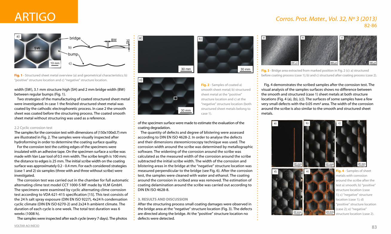
width (sW), 3.1 mm structure high (sh) and 2 mm bridge width (bW) between regular bumps (fig. 1).
Two strategies of the manufacturing of coated structured sheet metal were investigated. In case 1 the finished structured sheet metal was coated by the cathodic electrophoretic process. In case 2 the smooth sheet was coated before the structuring process. The coated smooth sheet metal without structuring was used as a reference.
2.2 Cyclic corrosion testThe samples for the corrosion test with dimensions of (150x100x0.7) mm are illustrated in fig. 2. The samples were visually inspected after hydroforming in order to determine the coating surface quality.
for the corrosion test the cutting edges of the specimens were insulated with an adhesive tape. On the specimen surface a scribe was made with Van Laar tool of 0.5 mm width. The scribe length is 100 mm; the distance to edges is 25 mm. The initial scribe width on the coating surface was approximately 0.2 - 0.4 mm. For each considered strategies (case 1 and 2) six samples (three with and three without scribe) were investigated.
The corrosion test was carried out in the chamber for full automatic alternating clime test model CCT 1000-s Mf made by VLM gmbh. The specimens were examined by cyclic alternating clime corrosion test according to VDA 621-415 specification [15]. This test consists of the 24 h salt spray exposure (DIN EN ISO 9227), 4x24 h condensation cyclic climate (DIN EN ISO 6270-2) and 2x24 h ambient climate. The duration of each cycle is one week. The total test duration was 6 weeks (1008 h).
The samples were inspected after each cycle (every 7 days). The photos
of the specimen surface were made to estimate the evaluation of the coating degradation.
The quantity of defects and degree of blistering were assessed according to dIN eN IsO 4628-2. In order to analyse the defects and their dimensions stereomicroscopy technique was used. The corrosion width around the scribe was determined by metallographic software. The widening of the corrosion around the scribe was calculated as the measured width of the corrosion around the scribe subtracted the initial scribe width. The width of the corrosion and blistering areas in the bridge at the “negative” structure location was measured perpendicular to the bridge (see fig. 6). After the corrosion test, the samples were cleaned with water and ethanol. The coating around the corrosion in scribed area was removed. The estimation of coating delamination around the scribe was carried out according to dIN eN IsO 4628-8.
3. RESUlTS and diScUSSiOn After the structuring process small coating damages were observed in the bridge area at the “negative” structure location (Fig. 3). The defects are directed along the bridge. At the “positive” structure location no defects were detected.
Fig. 3 - Bridge area extracted from marked position in Fig. 2 (c): a) structured
before coating process (case 1); b) and c) structured after coating process (case 2).
fig. 4 demonstrates the scribed samples after the corrosion test. The visual analysis of the samples surfaces shows no difference between the smooth and structured (case 1) sheet metals at both structure locations (fig. 4 (a), (b), (c)). The surfaces of some samples have a few very small defects with the 0.05 mm² area. The width of the corrosion around the scribe is also similar to the smooth and structured sheet metals.
Fig. 4 - samples of sheet
metals with corrosion
around the scribe after the
test a) smooth; b) “positive”
structure location (case
1); c) “negative” structure
location (case 1); d)
“positive” structure location
(case 2); e) “negative”
structure location (case 2).
Fig. 2 - samples of coated a)
smooth sheet metal; b) structured
sheet metal at the “positive”
structure location and c) at the
“negative” structure location (both
structured sheet metals belong to
case 1).
Fig. 1 - structured sheet metal overview (a) and geometrical characteristics; b)
“positive” structure location and c) “negative” structure location.
ARTIgO Corros. Prot. Mater., Vol. 32, Nº 3 (2013)
84VOLTAR AO INÍCIO
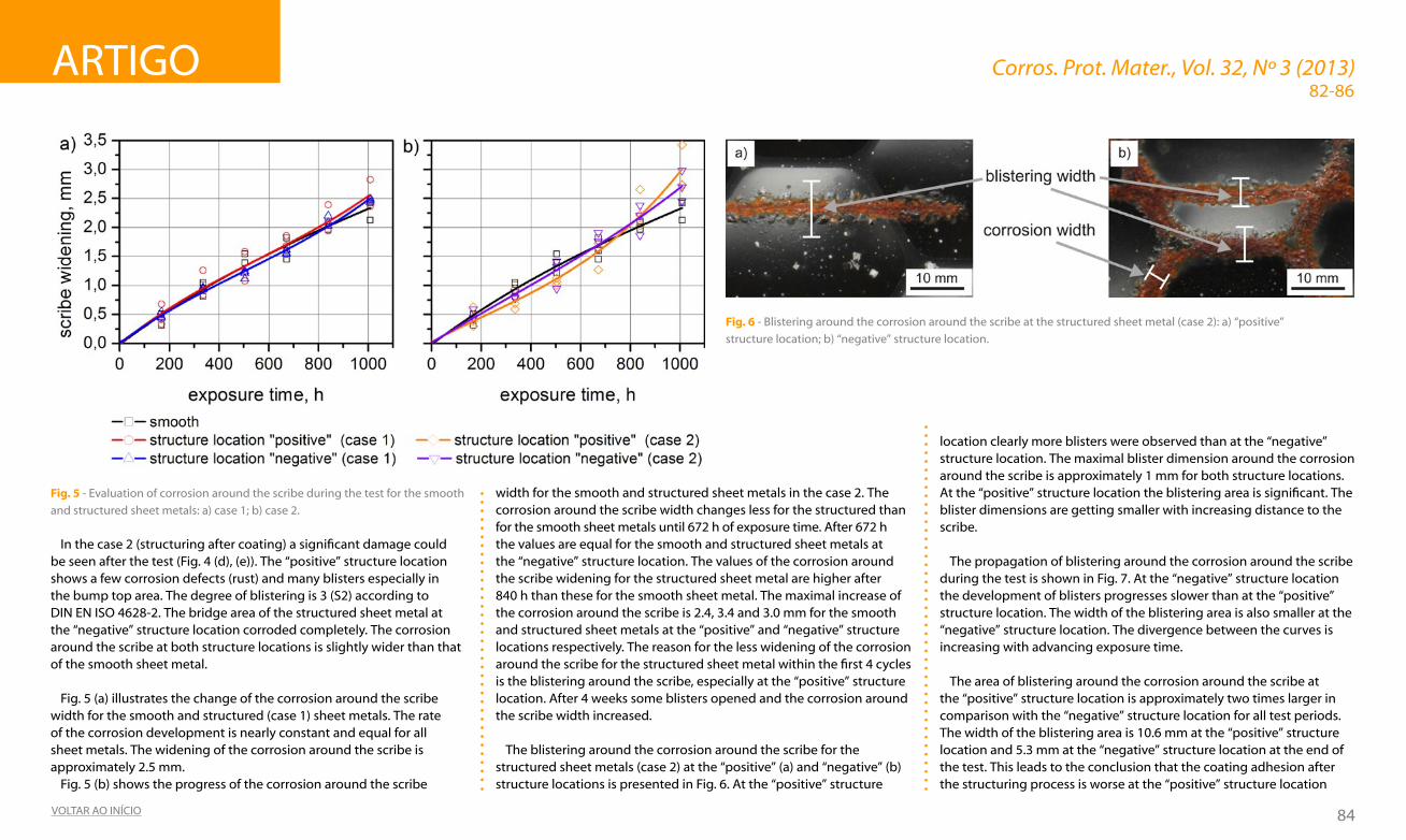
In the case 2 (structuring after coating) a significant damage could be seen after the test (Fig. 4 (d), (e)). The “positive” structure location shows a few corrosion defects (rust) and many blisters especially in the bump top area. The degree of blistering is 3 (s2) according to dIN eN IsO 4628-2. The bridge area of the structured sheet metal at the “negative” structure location corroded completely. The corrosion around the scribe at both structure locations is slightly wider than that of the smooth sheet metal.
fig. 5 (a) illustrates the change of the corrosion around the scribe width for the smooth and structured (case 1) sheet metals. The rate of the corrosion development is nearly constant and equal for all sheet metals. The widening of the corrosion around the scribe is approximately 2.5 mm.
fig. 5 (b) shows the progress of the corrosion around the scribe
width for the smooth and structured sheet metals in the case 2. The corrosion around the scribe width changes less for the structured than for the smooth sheet metals until 672 h of exposure time. After 672 h the values are equal for the smooth and structured sheet metals at the “negative” structure location. The values of the corrosion around the scribe widening for the structured sheet metal are higher after 840 h than these for the smooth sheet metal. The maximal increase of the corrosion around the scribe is 2.4, 3.4 and 3.0 mm for the smooth and structured sheet metals at the “positive” and “negative” structure locations respectively. The reason for the less widening of the corrosion around the scribe for the structured sheet metal within the first 4 cycles is the blistering around the scribe, especially at the “positive” structure location. After 4 weeks some blisters opened and the corrosion around the scribe width increased.
The blistering around the corrosion around the scribe for the structured sheet metals (case 2) at the “positive” (a) and “negative” (b) structure locations is presented in Fig. 6. At the “positive” structure
82-86
Fig. 5 - evaluation of corrosion around the scribe during the test for the smooth
and structured sheet metals: a) case 1; b) case 2.
Fig. 6 - Blistering around the corrosion around the scribe at the structured sheet metal (case 2): a) “positive”
structure location; b) “negative” structure location.
location clearly more blisters were observed than at the “negative” structure location. The maximal blister dimension around the corrosion around the scribe is approximately 1 mm for both structure locations. At the “positive” structure location the blistering area is significant. The blister dimensions are getting smaller with increasing distance to the scribe.
The propagation of blistering around the corrosion around the scribe during the test is shown in Fig. 7. At the “negative” structure location the development of blisters progresses slower than at the “positive” structure location. The width of the blistering area is also smaller at the “negative” structure location. The divergence between the curves is increasing with advancing exposure time.
The area of blistering around the corrosion around the scribe at the “positive” structure location is approximately two times larger in comparison with the “negative” structure location for all test periods. The width of the blistering area is 10.6 mm at the “positive” structure location and 5.3 mm at the “negative” structure location at the end of the test. This leads to the conclusion that the coating adhesion after the structuring process is worse at the “positive” structure location

ARTIgO Corros. Prot. Mater., Vol. 32, Nº 3 (2013)
85VOLTAR AO INÍCIO
than at the “negative” structure location. However, the “negative” structure location has the damaged position (bridge area) which corroded strongly.
A lot of blisters developed around the damaged coating in the bridges of the structured sheet metal (case 2) at the “negative” structure location. fig. 8 illustrates the progress of the corrosion and blistering width. After the first cycle the corrosion area width is already 3.3 mm. The blistering width is approximately 4 mm. With the exposure time the width of the blistering and corrosion areas increase proportionally. At the end of test the width of the corrosion area is 1.7 times and blistering area 1.8 times larger in comparison with this after 168 h of test.
The delamination area was assessed after removal of coating around the scribe. fig. 9 illustrates clearly the difference between the smooth
and structured sheet metals in the case 1 and case 2. It was possible to remove the coating around the scribe at the smooth and structured (case 1) sheet metals only in the corrosion area. The corrosion and delamination areas are equal. for the structured sheet metal in the case 2 the delamination area is larger than the corrosion area. fig. 9 (d) and 9 (e) shows that the coating delamination progresses in the bump area. The coating in the bridge area at the “positive” structure location and in the area near the bridge at the “negative” structure location has high adhesive. The probable reason is the compressive stress in this areas during the structuring which did not impaire the coating.
fig. 10 demostrates the delamination width for all investigated cases. It is evident that the structured sheet metals in the case 2 at the “positive” structure location have the biggest coating delamination width. The values for the smooth and structured sheet metals in the
case 1 are approximatelly identical. For the structured sheet metals in the case 2 the values are 7.8 and 3.0 mm at the “positive” and “negative” structure locations respectivelly.
The results in the case 1 show that there are no geometry effects on the corrosion properties. The coating system has a good adhesion with the structured sheet metal surface. The reason for the high corrosion in the case 2 is the deformation of the coating by the hydroforming process (see fig. 2). In spite of small plastic strains by the structuring [16], the coating was damaged at both structure locations. The corrosion protection is significantly reduced. The positions with the highest corrosion are the most strained areas. These are bumps at the “positive” structure location and bridges at the “negative” structure location. The following mechanisms of the coating degradation can be assumed. At the “positive” structure location the main reasons are the
82-86
Fig. 7 - development of blisters around the corrosion around the scribe for
the structured sheet metal (case 2).
Fig. 9 - samples of the sheet metals after removal of coating around the scribe
a) smooth; b) “positive” structure location (case 1); c) “negative” structure
location (case 1); d) “positive” structure location (case 2); e) “negative” structure
location (case 2).
Fig. 8 - Corrosion and blistering in the bridge area of the structured sheet
metals at the “negative” structure location (case 2) after different times of
corrosive environment exposure.

ARTIgO Corros. Prot. Mater., Vol. 32, Nº 3 (2013)
86VOLTAR AO INÍCIO
82-86
decrease of the adhesion between the coating and the substrate and the failure of the cohesion in the coating, because of the plastic strain. In the positions, where the cohesion and adhesion were destroyed (bump area), blisters were developed. The blistering in the bump area was estimated after 2 cycles. blistering was detected also in the bump area near the scribe after first cycle. With increasing exposure time the corrosion under coating started and progressed. After removal of coating the corrosion (rust) around the scribe was observed. At the “negative” structure location in the bridge area the strain during structuring is high. The reason for the coating degradation is not only the decrease of adhesion between the coating and the substrate but also the defects developed at the coating surface during the hydroforming. This damage initiated the rapid corrosion process in the bridge area.
4. cOnclUSiOnSThe organic coated structured sheet metals have been investigated by cyclic alternating clime corrosion test. The test has been carried out for the sheet metals which have been structured before (case 1) and after (case 2) coating process.
The results lead to conclusions that in case 1 the corrosion behaviour
for smooth and structured sheet metals weakly differs. It indicates that the sheet geometry has no significant influence on the corrosion behaviour of the organic-coated structured sheet metal. This protection strategy is preferred for the structured sheet metals with cathodic electrodeposition coating.
In case 2 the organic coating of the structured sheet metals has a low corrosion resistance. As could be expected, the structuring process affects the corrosion behaviour of the coating system. Consequently for further applications of the sheet metals, which structuration action needs to be done after the coating process (case 2), special corrosion protection process must be adopted.
acKnOWlEdGEMEnTSThis work was supported by the brandenburg Ministry of science, Research and Culture (MWfK) as part of the International graduate school at brandenburg university of Technology Cottbus (bTu).
REFEREncES[1] M. hoppe (umformverhalten strukturierter bleche), dissertation, Cottbus (2002).[2] h. P. degischer and s. Lüftl (Leichtbau), WILeY-VCh, Weinheim (2009).[3] V. Malikov, R. Ossenbrink, b. Viehweger and V. Michailov, Adv. Mat. Res., 418-420,
1294 (2012).[4] e. Kornienko and R. Ossenbrink and V. Michailov, Engineering Review, 31(2), 97 (2011).[5] s. fritzsche, R. Ossenbrink and V. Michailov, Key Eng. Mat., 473, 404 (2011).[6] e. Kornienko, R. Ossenbrink and V. Michailov, Corros. Sci., 69, 270 (2013).[7] T. brock, M. groteklaes and P. Mischke (Lehrbuch der Lacktechnologie), Vincentz
Network gmbh & Co Kg (2000).[8] d. Piazza, N. P. Lorandi, C. I. Pasqual, L. C. scienza and A. J. Zattera, Mat. Sci. Eng. A -
Struct., 528, 6769 (2011).[9] M. R. bagherzadeh, A. daneshvar and h. shariatpanahi, Surf. Coat. Tech., 206, 2057
(2012).[10] e. Almeida, I. Alves, C. brites and L. fedrizzi, Prog. Org. Coat., 46, 8 (2003).[11] X. Zhang, b. boelen, P. beentjes, J. M. C. Molb, h. Terryn and J. h. W. de Wit, Prog.
Org. Coat., 60, 335 (2007).[12] V. Lavaert, P. Praet, M. Moorsa, e. Wettinck and b. Verhegghe, Prog. Org. Coat., 39,
157 (2000).[13] R. P. edavan and R. Kopinski, Corros. Sci., 51, 2429 (2009).[14] s. Pietsch, W.-d. Kaiser and M. strutmann, Mater. Corros., 53 (5), 299 (2002).[15] VdA-Prüfblatt 621-415 (Anstrichtechnische Prüfungen, Prüfung des Korrosionss-
chutzes von Kraftfahrzeuglackierungen bei zyklisch wechselnder beanspru-chung) (1982).
[16] V. Malikov, R. Ossenbrink, b. Viehweger and V. Michailov, Int. J. Adv. Manuf. Tech., 63 (5-8), 449 (2012).
Fig. 10 - Coating delamination width on the specimen surfaces.
ESTRUTURAS DE BETÃO ARMADO
Protecção catódica
Prevenção catódica
Realcalinização
Dessalinização
Monitorização da corrosão
Inspecção e diagnóstico
PROTECÇÃO CATÓDICA
Tubagens
Tanques (interna e externa)
Equipamentos de processo
Estruturas portuárias e marinas
Navios
ESTUDOS DE CORROSÃO
Monitorização da corrosão On-line
Estudos de corrosão
Estudos de interferência
ww
w.ze
taco
rr.co
mze
taco
rr@ze
taco
rr.co
m

87VOLTAR AO INÍCIO
CAsO ReAL de CORROsãO Corros. Prot. Mater., Vol. 32, Nº 3 (2013)
1. dEScRiÇãO dO PROBlEMauma empresa foi confrontada com um incêndio na chaminé de uma caldeira de um sistema de recuperação de calor de gases de combustão. Após sinistro, o sistema de recuperação de energia denotou uma perda de eficiência. A questão colocada foi a de se essas anomalias teriam como causa a corrosão a altas temperaturas da estrutura metálica da tela filtrante. Efectivamente, a obstrução dos filtros justificaria a perda de rendimento, e no limite estaria na base de condições para que a temperatura subisse e levasse ao incêndio da caldeira.
2. aValiaÇãO da SiTUaÇãOA deslocação ao local permitiu constatar o seguinte:
a) Corpo da caldeira, fig. 1.
Indício de incêndio na parte superior, com os tubos de permuta deslocados em relação à sua inserção normal, com a chapa da parede de separação do “by pass” dos gases de exaustão empenada e denunciando uma perda de estanqueidade. Tal estará na origem das perdas de rendimento do sistema.
Fig. 1 – Zona superior
da caldeira.
A fig. 2 mostra a parte inferior do corpo da caldeira onde se vislumbra a presença de óxidos que se consideram associados à combustão.
José Inácio Martins(1)
INCÊNdIO NA CALdeIRA duM sIsTeMA de ReCuPeRAçãO de CALOR
Fig. 2 – Parte inferior da
caldeira.
b) Corpo do silenciador.
A fig. 3 mostra várias zonas deste componente do sistema de recuperação de energia.
A análise química de amostras recolhidas neste componente da caldeira mostrou o seguinte:- Existência de uma elevada espessura de produtos sólidos betuminosos nos filtros.- Produtos de corrosão, do ferro, que se associam ao incêndio.
3. cOnclUSõESem face das observações e análise químicas efectuadas pode concluir-se o seguinte:
1º - A inexistência de uma limpeza do silenciador, principalmente no corpo inferior, foi promovendo uma gradativa deposição de produtos betuminosos sólidos.2º - Esses sólidos foram obstruindo a saída dos gases de exaustão, o que levou a um aumento da temperatura no corpo da caldeira.3º - A falta de um sistema de controlo das perdas de carga ou aumento da temperatura dos gases de saída do corpo da caldeira não permitiu detectar a colmatagem do silenciador, em mais de cinquenta por cento da sua área, fundamentalmente no corpo inferior.
4º - Após uma limpeza do corpo da caldeira, o seu reinício de funcionamento teve condições de temperatura e oxigénio para promover a combustão dos hidrocarbonetos mais leves dos gases de exaustão, propagando-se até à chaminé, e só não teve continuidade por falta de oxigénio necessário para a quantidade de betuminosos depositados no filtro do silenciador.
4. acÇãO cORREcTiVa- Proceder a uma limpeza periódica dos filtros.- Instalar um sistema de controlo de temperatura ou pressão dos gases de exaustão.
(1)feuP, departamento de engª química, Rua dr. Roberto frias, s/N, 4200-465 Porto
e-mail: [email protected]
a) b)
c) d)
e) f)
a) b)
c) d)
e) f)
a) b)
c) d)
e) f)
a) b)
c) d)
e) f)
a) b)
c) d)
e) f)
a) b)
c) d)
e) f)
Fig. 3 – silenciador: a) Parte inferior do corpo superior; b) entrada do corpo
superior; c) Parte superior do corpo inferior; d) Parte interior do corpo inferior;
e) e f ) Pormenores do interior do corpo inferior.

88VOLTAR AO INÍCIO
NOVIdAdes Corros. Prot. Mater., Vol. 32, Nº 3 (2013)
Contrariamente à europa, onde a telha cerâmica é um material comum para os telhados, na América do Norte, e em particular nos estados unidos, o uso de telhas ou substratos metálicos em edifícios residenciais tem criado oportunidades para a utilização de revestimentos com pigmentos reflectores da radiação infravermelha. em telhados planos de edifícios comerciais, que não são muito visíveis, o uso de revestimentos brancos baseados em resinas acrílicas e fluoradas tem aumentado. Contudo, em telhados inclinados de edifícios residenciais, onde a estética é um problema crítico, o uso de cor é normal e corrente. Neste caso, a utilização de cores escuras resulta em maiores cargas térmicas devido à absorção de energia solar. A resposta a este desafio é o recurso a pigmentos especialmente desenvolvidos que reflectem uma boa percentagem da radiação solar que incide no telhado.
de acordo com o departamento de energia dos estados unidos, um telhado escuro pode absorver 90 % de radiação solar incidente e atingir temperaturas superiores a 65 ºC quando está calor e céu limpo, o que significa que as unidades de ar condicionado precisam de trabalhar muito mais para arrefecer o edifício. Por outro lado, telhados claros absorvem menos do que 50 % da energia solar. Existem pigmentos escuros especiais reflectores da radiação IV que podem ajudar a diminuir a absorção dos telhados escuros para os níveis dos telhados claros.
A energia solar é constituída aproximadamente por 2 % de radiação UV, 47 % de luz visível e 51 % de radiação IV. A reflectância solar total (TSR) é a quantidade total de radiação solar reflectida por uma superfície e é medida numa escala de 0 a 1. Assim, uma superfície que reflecte 60 % da luz solar tem uma TSR de 0,6. A emissividade térmica indica a quantidade de calor que uma superfície emite via radiação térmica e é também medida numa escala de 0 a 1, em que o 1 significa 100 % de emissão. As superfícies não metálicas têm valores de emissividade altas (maiores do que 0,8), enquanto superfícies metálicas brilhantes têm baixas propriedades de emissividade térmica. de acordo com alguns regulamentos internacionais, os “cool roofs” são telhados que têm quer uma elevada TsR quer uma elevada emissividade.
Coordenador: João Machado ([email protected])
PIgMeNTOs RefLeCTORes dA RAdIAçãO INfRAVeRMeLhA
Revestimentos contendo pigmentos reflectores da radiação IV, podem ser aplicados pela fábrica ou aplicados pelos empreiteiros consoante o substrato é novo ou antigo. As telhas de barro ou cimento podem ser coloridas usando um revestimento líquido que é cozido num forno. As telhas de cimento podem também ser fabricadas com pigmentos dispersos. Os telhados metálicos são geralmente revestidos com “coil coatings” em fábrica. A procura de telhados metálicos está a aumentar devido à disponibilidade de opções “cool roofing”.
Apesar da poupança energética ser o principal vector de interesse dos pigmentos reflectores de IV e dos “cool coatings”, não é o seu único benefício. A utilização de revestimentos com pigmentos reflectores de IV ajuda a reduzir as variações de temperatura que o substrato enfrenta entre o dia e a noite, diminuindo a sua tensão e deformação térmica e assim estendendo o seu tempo de vida. Além disso, a redução da temperatura de superfície conduz a uma diminuição da degradação do próprio revestimento e a um aumento da sua durabilidade.
Sendo as cores claras já significativamente reflectoras, são as cores de tonalidade escura (preto, castanho e verde) que requerem químicas especiais. O pigmento ideal absorveria 100 % na região visível do espectro e reflectiria 100 % na região infravermelha. Infelizmente, na realidade não há uma mudança automática da absorção para a reflexão mas uma alteração gradual. Como consequência, os pigmentos pretos reflectores de IV reflectem na região do vermelho e assim são efectivamente pretos acastanhados. Os fabricantes de pigmentos continuam a procurar complexos inorgânicos que tenham um comportamento muito mais diferenciado entre a região visível e região IV.
A maioria dos pigmentos pretos e castanhos reflectores de IV são baseados em complexos de ferro ou ferro e crómio, enquanto que os pigmentos verdes reflectores de IV são baseados em crómio III. Tem havido algum debate sobre o uso dos pigmentos baseados em crómio devido à possibilidade de contaminação por espécies de crómio VI que tem sido eliminado progressivamente noutras
aplicações, nomeadamente nos revestimentos anticorrosivos, devido à sua toxicidade. Existem alguns fabricantes a desenvolver pigmentos alternativos baseados em manganésio que exibem uma boa absorção na região visível e boa reflexão na região IV. Apesar de alguns pigmentos baseados em manganésio estarem já no mercado, dado que são mais caros e apresentam alguns problemas de resistência em exterior, que têm ainda que ser resolvidos, os pigmentos baseados em crómio, de momento, correspondem ainda à maior fatia de mercado.
Os pigmentos reflectores de IV baseados em manganésio são tão duráveis como os complexos inorgânicos mas apresentam uma interacção com as resinas dos revestimentos. de facto, quando expostos à radiação UV, geram radicais que degradam lentamente as resinas orgânicas e consequentemente conduzem a uma falha mais rápida dos revestimentos.
Assim, num futuro próximo, os pigmentos baseados em ferro e crómio continuarão a ser utilizados em revestimentos para “cool roofing”. Os “cool coatings” são também utilizados em navios e plataformas de petróleo. Nessas aplicações, é também desejável aumentar a eficiência energética, mas os revestimentos claros não são adequados porque a luminosidade no mar pode afectar a visão. Assim, as cores escuras baseadas em pigmentos reflectores de IV são muito atractivas. As tintas para camuflagem para aplicações militares usam também muitas vezes pigmentos reflectores verdes que imitam o espectro da clorofila, de modo a que os objectos pintados se confundam com a natureza.
in “Polymers Paint Colour Journal”, July 2013

89VOLTAR AO INÍCIO
ReguLAMeNTAçãO Corros. Prot. Mater., Vol. 32, Nº3 (2013)
Coordenadora: Manuela Cavaco([email protected])
COMuNICAçãO dOs PeRIgOs NA INdúsTRIA de TINTAs - PAssAR As MeNsAgeNs CeRTAs PARA Os CLIeNTes e OuTRAs PARTes INTeRessAdAs
A comunicação de informações sobre os perigos dos produtos é uma questão de longa data, mas está em constante evolução.
Todas as empresas são, até certo ponto, afetadas pelas regras e a complexidade é cada vez maior, por isso os guias de orientação para a indústria e as normas gerais são tão importantes hoje como eram nos primeiros dias das antigas diretivas - talvez até mais.
Classificação, rotulagem e embalagemO Regulamento Nº 1272/2008, designado por Regulamento CLP, que
implementa o sistema globalmente harmonizado das Nações unidas (ghs) na europa, vai tornar-se obrigatório a partir de 1 de Junho de 2015 para as misturas, o que constitui a grande maioria dos produtos de pintura.
O regulamento CLP está sujeito a um programa evolutivo constante de “adaptação ao progresso técnico”, para atualizar a lista de classificações oficiais harmonizadas de substâncias no Anexo VI e/ou alinhar o regulamento com a mais recente edição revista do ghs.
O ghs é atualizado a cada dois anos e estas revisões são integradas no regulamento CLP cerca de dois anos mais tarde. A ue não pode alterar os critérios, por isso é importante para a indústria influenciar o conteúdo do ghs ao nível da ONu.
Fichas de dados de segurançaenquanto o rótulo do produto é fundamental para os consumidores, as fichas de dados de segurança (sds) são uma importante ferramenta de comunicação de risco para os utilizadores industriais e profissionais.
Na ue, os requisitos das sds fazem parte do ReACh e, à medida que as substâncias vão sendo registadas no âmbito do ReACh, as sds podem passar a apresentar informação adicional sobre Cenários de Exposição (CE).
informação aos centros antivenenosentre 2010-2012, a Comissão europeia procedeu a uma revisão da possibilidade de harmonizar a informação sobre misturas perigosas, que é enviada aos Centros Antivenenos de toda a ue. Concluiu-se que tal harmonização é possível e bem-vinda, e as discussões têm continuado sobre uma série de aspectos práticos da notificação. Na situação actual nem todos os Estados-membros exigem notificar os Centros Antivenenos, o que não é o caso de Portugal onde existe a obrigação de notificação ao CIAV (Centro de Informação Antivenenos).
A Comissão europeia planeia um primeiro projecto de proposta legislativa até ao final de 2013, assim como dar início a uma revisão legal e estudo de viabilidade. em 2014 esperamos ter uma imagem mais clara dos requisitos de comunicação futuros e do período de transição, para que possamos planear o seu cumprimento.
Informação extraída do CEPE Annual Report 2013.
PubLICAçÕes eM desTAqueiMPEdancE SPEcTROScOPYapplications to Electrochemical and dielectric Phenomena
author: Vadim f. Lvovich. Editores: John Wiley and sons, 2012, 368 p.iSBn: 978-0-470-62778-5 (versão impressa)
este livro tem como características principais a apresentação das considerações teóricas para lidar com a modelagem, circuitos equivalentes e equações matemáticas no domínio complexo.Apresenta um balanço de considerações teóricas e resolução de problemas prácticos de espectroscopia de impedância eletroquímica.
Incorpora os resultados das últimas duas décadas de pesquisa sobre as teorias e aplicações de espectroscopia de impedância, incluindo análises mais detalhadas das aplicações de métodos de impedância em coloides industriais, sensores e dispositivos biomédicos, e filmes poliméricos supercapacitivos. Aborda todos os tópicos necessários para ajudar os leitores a entender rapidamente como aplicar os métodos de espectroscopia de impedância aos seus problemas de investigação. Ajuda também o leitor a identificar se a espectroscopia de impedância é o método mais adequado para o seu problema particular.Inclui informação de como executar correctamente as medidas de impedância, interpretar os resultados, comparar os resultados com os anteriormente publicados para sistemas químicos semelhantes, e usar as fórmulas matemáticas correctas para verificar a exactidão dos dados.
José Inácio Martins ([email protected])

90VOLTAR AO INÍCIO
NOTÍCIAs bReVes Corros. Prot. Mater., Vol. 32, Nº 3 (2013)
euROCORR 2013
O Congresso europeu de Corrosão, euROCORR, é um dos mais importantes eventos na área da corrosão e protecção contra a corrosão e uma referência mundial neste domínio. Organizado pela federação europeia de Corrosão (efC), este evento é co-organizado anualmente em vários países da europa por sociedades membro da efC.
em 2013, o euROCORR foi organizado em Portugal, pela sociedade Portuguesa de Materiais (sPM) ente 1 a 5 de setembro, no Centro de Congressos do estoril.
A Comissão Organizadora Local foi liderada pela Prof.ª fátima Montemor e pelo Prof. João salvador, do Instituto superior Técnico, e contou com a preciosa ajuda de vários colegas que desenvolvem actividade científica e tecnológica na área de intervenção do Congresso.
O EUROCORR 2013 foi dedicado ao tema “ Controle da Corrosão para um Céu Azul” e entre os vários tópicos abordados incluiu-se uma workshop intitulada “Estratégias anti-corrosão para sistemas de produção de energia”.
O euROCORR 2013 foi, até à presente data, o maior evento jamais realizado. O número de participantes atingiu os 873, o que fez deste euROCORR o mais participado desde sempre. saliente-se que cerca
de 21% dos participantes foram estudantes, o que mostra o quanto importante é o euROCORR para a formação de jovens investigadores.
O maior número de participantes foi proveniente de países europeus, destacando-se a frança com 129 participantes e a Alemanha com 116. Portugal foi o terceiro pais mais representado com 62 participantes. Nos 20 países mais representados destacam-se ainda a China, Japão, Austrália, estados unidos e brasil, que conferiram ao euROCORR 2013 uma dimensão mundial.
O euROCORR 2013 contou com 432 apresentações orais, distribuídas por 32 sessões distintas. Contou ainda com uma sessão de Pósters muito dinâmica, onde foram expostos 183 trabalhos.
Paralelamente decorreu uma exposição onde representantes de várias tecnologias de prevenção contra a corrosão e fabricantes de equipamento demonstraram os últimos desenvolvimentos nas suas respetivas áreas de intervenção.
É com muito orgulho que a Comissão Organizadora agradece a todos os participantes, com uma palavra de apreço muito especial para todos os colegas portugueses que estiveram presentes neste evento. um grande obrigado a todos.
um caloroso abraçofátima Montemor e João salvador fernandes
seMINáRIO APT 2014
A Associação Portuguesa de Tintas – APT, vai realizar no dia 21 de Março de 2014 o seu seminário Anual.
do Programa constarão temas que interessam às diversas
áreas empresariais e a APT tem como objectivo reunir mais de 150
empresários e gestores de topo do mercado e dos fornecedores de matérias
primas e equipamentos.
CePe – CONfeRÊNCIA ANuAL e AsseMbLeIA geRALsob o tema, “Do colours shine brighter in Central and Eastern Europe?” decorreu em Praga, de 25 a 27 de setembro de 2013, este importante evento do sector de Tintas.
Este ano o tema da Conferência centrou-se nas expectativas de crescimento na europa Central e Oriental, onde muitas empresas europeias de tintas iniciaram negócios que vão desde a distribuição à produção. especialistas de renome deram a conhecer os seus pontos de vista sobre as perspectivas económicas e as directrizes para compreender a dinâmica do mercado nesta região.
Para além da Conferência plenária, realizaram-se sessões paralelas dedicadas aos sectores decorativo e industrial.
este evento que reuniu cerca de 130 participantes constitui um importante fórum para os industriais do sector.
91VOLTAR AO INÍCIO
CALeNdáRIO Corros. Prot. Mater., Vol. 32, Nº 3 (2013)
título local data contactos
22nd World Energy Congress“Securing Tomorrow’s
Energy Today”
CoreiaDaegu
13 – 17 Out www.daegu2013.kr
ECASIA’1315th European Conference on Applications of surface
and Interface Analysis
ItáliaSardenha
13 – 18 Out
http://people.unica.it/ecasia13
EUROCOAT 2013 Itália Piacenza
22 - 24 Out
www.eurocoat-expo.com
International Workshop on Environment and Alternative Energy
ItáliaFrascati
22- 25 Out
http://teerm.nasa.gov/workshop.htm
ISCE 2013International Steel
Construction Exhibition
PortugalPorto
23 – 26 Out www.cmm.pt/isce2013
OREC2013Offshore renewable energy
conferenceSingapura 29 – 30
Outhttp://erian.ntu.edu.sg/conference_workshop
Dia Mundial dos Materiais PortugalCoimbra 6 Nov www.spmateriais.pt
Corrosion & Prevention 2013
AustráliaBrisbane
10-13 Nov
www.acaconference.com.au
Bring on the Heat Europe AlemanhaFrankfurt
14 – 15 Nov. www.efcweb.org
título local data contactos
Seminário WavEC 2013 PortugalLisboa 25 Nov. www.wavec.org
Corrosion Protection – Key to Energy and
Environmental Safety
Rússia Moscovo 3 – 5 Dez www.oilconference.ru
3rd International Conference on Corrosion Mitigation and Surface Protection
Technologies
EgiptoLuxor
9 – 12 Dez http://egycorr.net/
título local data contactos
2nd International Symposium on Anodizing Science and Technology
(AST2014)
JapãoHokkaido 4 – 6 Jun
http://labs.eng.hokudai.ac.jp/labo/elechem/
AST2014/
COSI 201410th Coatings Science
International
HolandaNoordwijk
23 – 27 Jun
www.coatings-science.com
6èmes Journées Protection Cathodique
FrançaJuan-Les-Pins
24 – 26 Jun
www.cefracor.org/PCRA2014/
65th Annual Meeting of the ISE
SuiçaLausanne
31 Ago – 5 Set
http://annual65.ise-online.org
EUROCORR’2014 ItáliaPisa
8 – 12 Set www.eurocorr2014.org/
LATINCORR 2014IX Congresso
Latinoamericano de Corrosão
ColombiaMedellín
28 – 31 Out www.latincorr2014.org/
19th ICCInternational Corrosion
Congress
CoreiaJeju 2 – 6 Nov www.19thicc.com
ICOE20145th International Conference
on Ocean Energy
CanadáHalifax 4 – 6 Nov www.icoe2014canada.
org
Matériaux 2014 FrançaMontpellier
24 – 28 Nov www.ffmateriaux.org
2014título local data contactos
XIV Portuguese Conference on Fracture (PCF 2014)
PortugalRégua 6 – 7 Fev http://pcf2014.utad.pt
Corrosion 2014 / NACE EUASan Antonio
9 – 13 Mar www.nace.org
XXI Congreso de la Sociedad Iberoamericana de Electroquímica (SIBAE)
ChileLa Serena 6 -11 Abr www.sibae2014.cl
CLME20147º Congresso Luso-Moçambicano de
Engenharia
MoçambiquePemba
14 – 18 Abr
http://topical13.ise-online.org/
International Symposium on Corrosion & Materials
Degradation (ISCMD 2014)
MalásiaKuala Lumpur
13 – 16 Mai
http://www.imtce2014.com/iscmd_2014.php
20132013 2014

92VOLTAR AO INÍCIO
INsTRuçÕes PARA Os AuTORes Corros. Prot. Mater., Vol. 32, Nº 3 (2013)
TiPOS dE cOnTRiBUiÇõESserão considerados para publicação pela direcção editorial artigos originais, comunicações breves, artigos de revisão e outros conteúdos especiais (e.g. casos reais, formação) que se integrem no domínio científico da corrosão/degradação e protecção de materiais.
ManuscRItosOs manuscritos podem ser escritos em português, inglês ou espanhol e enviados por e-mail ([email protected]). O ficheiro deve ser elaborado em formato de documento “word”. Os manuscritos não devem exceder 25 páginas A4, incluindo tabelas e figuras, com espaçamento duplo entre linhas e escritos no tipo e tamanho de letra “Arial 12”. As margens das folhas devem ter uma dimensão de 2,0 cm. A paginação deve ser feita de forma sequencial, incluindo a primeira página e ao centro.
Os artigos devem ter, por ordem sequencial, os seguintes itens:- Título curto e explícito, com letra a negrito, em maiúsculas e com
dimensão 12.- Autores (texto centrado) com asterisco indicando o autor a quem
deve ser dirigida a correspondência. A afiliação (número de telefone, fax, e-mail) deve ser numerada e colocada sequencialmente em nota de pé de página ((1), (2),…).
- O Resumo não pode exceder 125 palavras e com espaçamento simples entre linhas.
- As Palavras-chave (máximo 6 palavras) com texto a negrito, em itálico e alinhado à esquerda. se o manuscrito for escrito em Inglês ou espanhol, os autores devem acrescentar o título, resumo e palavras-chave em Português. se for escrito em Português os autores devem escrever o título, resumo e palavras-chave em Inglês.
- Na Introdução os autores devem enquadrar adequadamente o artigo no seu contexto científico ou tecnológico, bem como o objectivo do trabalho. Por exemplo, devem indicar, de forma resumida e com referências, qual a literatura existente nessa área específica, evidenciando desse modo a contribuição do artigo para o conhecimento.
- Nos itens Metodologias Experimentais, Resultados e Discussão todas as unidades devem ser especificadas de acordo com o sistema SI. As figuras e as tabelas devem ser apresentadas centradas no texto, de um modo claro e, tanto quanto possível, compreensíveis sem ter
de recorrer a outra informação. Os cabeçalhos das tabelas devem ser centrados e a negrito. Todos os gráficos, desenhos, fotografias e simbologia especial deverão ser apresentados em boa qualidade (600 dpi) e enviados separadamente do documento “Word” em formato jpeg, bmp ou tiff. As figuras devem ser legendadas como “Fig.”.
- Os manuscritos devem terminar com conclusões claras, excepto nos casos onde isso não é apropriado (e.g. artigos de revisão).
- Os Agradecimentos não devem exceder 5 linhas com tamanho de letra 10.
- As Referências devem ser numeradas sequencialmente, tal como surgem no texto, entre parênteses rectos [1] e apresentadas no fim do manuscrito, incluindo sempre os autores, o título do trabalho referido (ou livro), o título da revista em itálico, abreviado de acordo com o "Chemical Abstracts Service Source Index", seguido do número do volume, número (se existir), página e ano de publicação entre parênteses ou, no caso dos livros, o editor, a cidade e o ano.
eXeMPLO:Revistas: [63] d. Wang and g.P. bierwagen, Prog. Org. Coat., 64, 327 (2009).
Livros:[64] e. Almeida (Corrosão Atmosférica do Aço), in Corrosão Atmosférica. Mapas de Portugal (M. e. M. Almeida e M. g. s. ferreira, ed.), INeTI/IMP/LTR, Lisboa, Portugal, p. 15 (1997).
“Proceedings”:[65] C. Arroyave, f. echeverria and f. herrera (NO2 Measurements in Atmospheric Corrosion studies) in Proceedings of symposium on Outdoor Atmospheric Corrosion, May, Phoenix, USA (2001).
Normas:[66] ISO 9227: 2006. (Corrosion tests in artificial atmospheres – Salt spray tests), IsO, geneve, switzerland (2006).
As abreviaturas das revistas devem estar de acordo com as seguintes indicações:
Index Medicus journal abbreviations: http://www.nlm.nih.gov/tsd/serials/lji.html;
List of title word abbreviations: http://www.issn.org/2-22661-LTWA-online.php;
CAs (Chemical Abstracts service): http://www.cas.org/sent.html.
Os títulos mencionados anteriormente devem ser escritos a negrito, com o texto alinhado à esquerda, numerados e em maiúsculas (e.g. 1. inTROdUÇãO, 2. METOdOlOGiaS, etc.).
Todos os manuscritos submetidos para publicação serão enviados à avaliação por pares. uma vez recebido o manuscrito, a direcção editorial reserva-se o direito de indicar aos autores qualquer outra recomendação aqui não mencionada. Os autores devem verificar cuidadosamente as provas e enviar as versões corrigidas por e-mail ([email protected]), durante os dois dias imediatos ao da recepção das referidas provas.