Embed Size (px)
Citation preview
Paula
Alex
andr
a Fer
nand
es M
ontei
ro
Abril de 2014UMin
ho |
201
4Ta
ilori
ng C
MM
I-DEV
and
RUP
Fram
ewor
ks fo
r M
L2/3
-Com
plia
nce
Anal
ysis
Universidade do MinhoEscola de Engenharia
Paula Alexandra Fernandes Monteiro
Tailoring CMMI-DEV and RUPFrameworks for ML2/3-ComplianceAnalysis
Programa de Doutoramento em Informáticadas Universidades do Minho, de Aveiro e do Porto
Universidade do Minho

Abril de 2014
Tese de DoutoramentoPrograma de Doutoramento em Informáticadas Universidades do Minho, de Aveiro e do Porto
Trabalho efectuado sob a orientação deProfessor Doutor Ricardo J. MachadoProfessor Doutor Rick Kazman
Paula Alexandra Fernandes Monteiro
Tailoring CMMI-DEV and RUPFrameworks for ML2/3-ComplianceAnalysis
Universidade do MinhoEscola de Engenharia
Universidade do Minho
iii
Agradecimentos
Ao Martinho e aos meus pais Domingos e Ester, o meu mais sincero agradecimento, por toda a
paciência e compreensão que demonstraram estes anos.
Aos meus orientadores, Professor Doutor Ricardo J. Machado e Professor Doutor Rick Kazman,
por todo o apoio e orientação para a realização deste trabalho.
Ao Nuno Ferreira por toda ajuda e discussões para ultrapassar alguns dos obstáculos que
precisaram de ser ultrapassados.
À I2S - Informática Sistemas e Serviços SA, e em particular à Dra. Cristina Henriques, pela
possibilidade que me deram de realizar este trabalho, bem como por todo o apoio prestado
para a minha integração na empresa.
Ao Instituto CCG/ZGDV, em particular, ao Eng. Eduardo Pinto (diretor executivo) e à Engª. Ana
Lima (coordenadora de desenvolvimento do Laboratório EPMQ) por me terem apoiado na fase
final, facilitando os horários de trabalho de modo a concluir a escrita desta tese. Também
gostaria de agradecer ao CCG e à Engª. Ana Lima pelo apoio prestado para a realização do case
study II.
Gostaria de agradecer ao Pedro Borges, Fátima Mandjam e Cláudia Simões (alunos de
mestrado) a cooperação demonstrada no trabalho de equipa, na instanciação do RUP e na
recolha de dados dos case studies.
A todos os que direta ou indiretamente permitiram a conclusão deste trabalho, o meu muito
obrigado.
Apoio Financeiro
Este trabalho foi desenvolvido com o apoio da Fundação para a Ciência e Tecnologia e da I2S -
Informática Sistemas e Serviços SA., através de uma Bolsa de Doutoramento em Empresa.

v
Abstract
The Capability Maturity Model Integration is a reference model composed of a set
of guidelines that has to be implemented to attain a specific level of maturity in a
particular set of process areas. This model aims to establish a set of "best
practices" that should be used to ensure the software development with a high
degree of quality. However, CMMI is not widely adopted by small businesses. Its
adoption by these companies is somewhat complex since, in its guidelines, it
merely indicates what to do, but it does not indicate how to implement each
guideline.
The Rational Unified Process is a software development methodology, which has
as its main objective to avail its users the possibility of the software developing
high-quality, within time and budget.
This thesis aims to contribute a set of solutions that can be followed by small
organizations, in order to implement a more streamlined process model that
guarantees an increase in the quality of their products.
This thesis adopts and validates a tailoring of the Rational Unified Process allowing
it to be more easily implemented by small businesses or small software teams.
This thesis presents a study of the dependencies between all the Capability
Maturity Model Integration process areas, in order to enable the understanding of
what the implementation impact is of a given process area in the other process
areas. Finally, we present a mapping between the Capability Maturity Model
Integration and the Rational Unified Process, which aims to help small software
development teams in the implementation of the Maturity Level 2 (presented in
more detail) and Maturity Level 3 of the Capability Maturity Model Integration.
This mapping specifies what team members have to perform in order to
implement most of the guidelines that the Capability Maturity Model Integration
requires for each of their maturity levels.
Keywords: Rational Unified Process, RUP, Capability Maturity Model Integration, CMMI, CMMI ML 2, CMMI CL3, CMMI ML3, RUP Roles

vii
Resumo
O Capability Maturity Model Integration é um modelo de referência que contém
um conjunto de orientações necessárias para atingir um determinado nível de
maturidade em áreas de processo específicas. Este modelo tem como objetivo
estabelecer um conjunto de "melhores práticas" que devem ser utilizadas para
garantir o desenvolvimento de software com um elevado grau de qualidade. No
entanto o CMMI não é muito adotado por pequenas empresas. A sua adoção por
estas empresas torna-se ligeiramente complexa, uma vez que nas suas
orientações apenas é indicado o que se deve fazer e não o como se pode fazer.
O Rational Unified Process é uma metodologia de desenvolvimento de software
que tem como principal objetivo garantir aos seus utilizadores o desenvolvimento
de software de alta qualidade dentro do tempo e custo previsto.
Esta tese pretende contribuir com um conjunto de soluções, que as pequenas
empresas podem seguir, de modo a implementarem de uma forma mais
simplificada um modelo de processos que lhes garanta um aumento da qualidade
dos seus produtos.
Esta tese adota e valida uma simplificação do Rational Unified Process permitindo
que este seja mais facilmente implementado por pequenas empresas ou
pequenas equipas de software. Esta tese apresenta um estudo das dependências
existentes entre as várias áreas de processo do Capability Maturity Model
Integration de modo a permitir a compreensão de qual o impacto que a
implementação de uma determinada área de processo tem nas restantes áreas
existentes. Por fim, é apresentado um mapeamento entre o Capability Maturity
Model Integration e o Rational Unified Process, que pretende orientar as
pequenas equipas de desenvolvimento a implementar nível 2 (apresentado de um
modo mais detalhado) e 3 do Capability Maturity Model Integration. Este
mapeamento permite indicar aos elementos da equipa o que tem de fazer para
conseguir implementar a maior parte das orientações que o Capability Maturity
Model Integration impõe para cada um dos seus níveis de maturidade.
Palavras-Chave: Rational Unified Process, RUP, Capability Maturity Model Integration, CMMI, CMMI ML 2, CMMI CL3, CMMI ML3, RUP Roles

ix
Table of Contents
Chapter 1............................................................................................................................................... 1
1 Introduction ............................................................................................................................ 3
1.1 Capability Maturity Model Integration .................................................................................... 3
1.2 Rational Unified Process ....................................................................................................... 11
1.3 Goals and Research Strategy ................................................................................................ 14
1.4 Contributions ....................................................................................................................... 16
1.5 Structure of this Document .................................................................................................. 16
Chapter 2............................................................................................................................................. 19
2 CMMI and RUP Research Efforts ............................................................................................ 21
2.1 Introduction ......................................................................................................................... 21
2.2 CMMI ................................................................................................................................... 22
2.2.1 CMMI Studies ............................................................................................................... 26
2.3 RUP ...................................................................................................................................... 30
2.4 Conclusion ............................................................................................................................ 36
Chapter 3............................................................................................................................................. 39
3 Tailoring the Rational Unified Process .................................................................................... 41
3.1 Introduction ......................................................................................................................... 41
3.2 Step 1: Getting One RUP Base Model.................................................................................... 42
3.2.1 Mapping RUP Roles into Base Model Roles ................................................................... 48
3.2.2 Accumulation of Roles .................................................................................................. 56
3.3 Step 2: Instantiating to Get One RUP Reduced Model........................................................... 57
3.4 Examples of Some Essential Roles......................................................................................... 64
3.4.1 Integrator ..................................................................................................................... 66
3.4.2 Implementer ................................................................................................................. 74
3.5 Conclusion ............................................................................................................................ 76
Chapter 4............................................................................................................................................. 79
4 Dependencies inside the CMMI-DEV Framework .................................................................. 81
4.1 Introduction ......................................................................................................................... 81
4.2 Discovering Dependencies between CMMI-DEV Process Areas ............................................. 82
4.2.1 Elementary Dependency Analysis.................................................................................. 82
4.2.2 Dependencies of CMMI Process Areas .......................................................................... 84
4.2.3 ML-2 Centric Dependency Analysis ............................................................................... 89
4.2.4 Analyzing ML2||CL3 in V&V Process Areas ................................................................... 90
4.3 Discovering Dependencies between CMMI-DEV Categories .................................................. 93
4.3.1 Engineering Category .................................................................................................... 93
4.3.2 Project Management Category ..................................................................................... 97
4.3.3 Process Management Category ................................................................................... 101
4.3.4 Support Category ........................................................................................................ 105
4.4 Updating Dependency Analysis for CMMI-DEV v1.3 ............................................................ 109
4.5 Conclusion .......................................................................................................................... 110
Chapter 5........................................................................................................................................... 113
5 Mapping CMMI and RUP Process Frameworks .................................................................... 115
5.1 Introduction ....................................................................................................................... 115
x
5.2 General CMMI-RUP Mapping for ML2 and ML3 .................................................................. 116
5.2.1 Reduced Model Roles for ML2 and ML3 Process Areas ............................................... 123
5.3 Detailing Mappings for Supporting Project Proposals (PP and REQM Alignment) ................ 126
5.4 Detailing Mappings for Supporting ML2 Projects Execution ................................................ 130
5.5 Evolution of CMMI-RUP Tasks Accomplishment ................................................................. 142
5.6 Conclusion .......................................................................................................................... 148
Chapter 6........................................................................................................................................... 151
6 Case Studies Analysis .......................................................................................................... 153
6.1 Introduction ....................................................................................................................... 153
6.2 Case Study I - Assessing RUP Reduced Model ..................................................................... 154
6.3 Case Study II - Assessing RUP Support for Project Proposals ............................................... 156
6.4 Case Study III - Assessing RUP Support for ML2 Projects Execution ..................................... 163
6.5 Conclusion .......................................................................................................................... 173
Chapter 7........................................................................................................................................... 175
7 Conclusion .......................................................................................................................... 177
7.1 Focus of the Work .............................................................................................................. 177
7.2 Synthesis of Research Efforts .............................................................................................. 178
7.3 Synthesis of Scientific Results ............................................................................................. 179
7.4 Future Work ....................................................................................................................... 180
References .................................................................................................................................... 183
Annex A: Case Study I - Assessing RUP Reduced Model ................................................................ 189
Annex B: Case Study II - Assessing RUP Support for Project Proposals .......................................... 193
Annex C: Case Study III - Assessing RUP Support for ML2 Projects Execution................................ 199
xi
Acronyms
CMMI Capability Maturity Model Integration
CMMI-DEV Capability Maturity Model Integration for Development
PA Process Area
SG Specific Goal
SP Specific Practice
ML Maturity Level
CL Capability Level
CMM Capability Maturity Model
SEI Software Engineering Institute
RUP Rational Unified Process

xiii
Table of Figures
Figure 1 History of the CMMs (CMMI Product Team, 2010b).................................................................. 4 Figure 2 Continuous Representation (CMMI Product Team, 2006, 2010b) ............................................. 5 Figure 3 Staged Representation (CMMI Product Team, 2006, 2010b) ..................................................... 6 Figure 4 RUP Architecture (IBM, 2006b) ............................................................................................... 12 Figure 5 Mappings of Base Model ........................................................................................................ 50 Figure 6 Comparative table between the base model and the reduced model ..................................... 58 Figure 7 Communication Flow (Internal and External) .......................................................................... 65 Figure 8 PA15-centric dependency analysis .......................................................................................... 84 Figure 9 ML-2 centric dependency analysis graph ................................................................................ 86 Figure 10 Dependencies of process areas of the CMMI maturity level 3 ............................................... 87 Figure 11 Global dependencies between CMMI process areas ............................................................. 88 Figure 12 a) Elementary Dependency Analysis for {PA11} and b) Elementary Dependency Analysis for
{PA12} .......................................................................................................................................... 91 Figure 13 Dependencies between CMMI ML2 and V&V ({PA11} and {PA12}) Process Areas ................. 92 Figure 14 Based on Engineering Process Areas interaction (Chrissis, et al., 2006; CMMI Product Team,
2006) ............................................................................................................................................ 94 Figure 15 Dependencies of Engineering Process Areas ......................................................................... 96 Figure 16 Based on Basic Project Management Process Areas interaction (Chrissis, et al., 2006; CMMI
Product Team, 2006) .................................................................................................................... 97 Figure 17 Based on Advanced Project Management Process Areas interaction (Chrissis, et al., 2006;
CMMI Product Team, 2006) .......................................................................................................... 98 Figure 18 Dependencies of Project Management Process Areas ......................................................... 100 Figure 19 Based on Basic Process Management Process Areas interaction (Chrissis, et al., 2006; CMMI
Product Team, 2006) .................................................................................................................. 102 Figure 20 Based on Advanced Process Management Process Areas interaction (Chrissis, et al., 2006;
CMMI Product Team, 2006) ........................................................................................................ 102 Figure 21 Dependencies of Process Management Process Areas ........................................................ 104 Figure 22 Based on Basic Support Process Areas interaction (Chrissis, et al., 2006; CMMI Product Team,
2006) .......................................................................................................................................... 106 Figure 23 Based on Advanced Support Process Areas interaction (Chrissis, et al., 2006; CMMI Product
Team, 2006) ............................................................................................................................... 106 Figure 24 Dependencies of Support Process Areas ............................................................................. 108 Figure 25 Type A tasks Accomplishment ............................................................................................. 143 Figure 26 Type B tasks Accomplishment ............................................................................................. 143 Figure 27 Type C tasks Accomplishment ............................................................................................. 144 Figure 28 Type D tasks Accomplishment............................................................................................. 145 Figure 29 Type E tasks Accomplishment ............................................................................................. 145 Figure 30 Type F tasks Accomplishment ............................................................................................. 146 Figure 31 Type G tasks Accomplishment............................................................................................. 146 Figure 32 Type H tasks Accomplishment............................................................................................. 147 Figure 33 Comparison of Type Tasks Accomplishment ....................................................................... 148 Figure 34 Case Study 1 and Case Study 2 Performance Analysis ......................................................... 163 Figure 35 Project Planning (M1) Assessment ...................................................................................... 166 Figure 36 Inception(M2) Assessment.................................................................................................. 168 Figure 37 Elaboration (M3) Assessment ............................................................................................. 169 Figure 38 Construction (M4) Assessment ........................................................................................... 170 Figure 39 Teams Assessment Evolution .............................................................................................. 171 Figure 40 Comparison between Ideal and Teams Coverage Average by PA and Priority ..................... 172

xiv
xv
List of Tables
Table 1.Table of all CMMI process areas............................................................................................... 23 Table 2 CMMI specific goals example ................................................................................................... 23 Table 3 CMMI generic goals for the continuous and staged representations ........................................ 24 Table 4 Trimming RUP for mall Projects at Inception Phase (IBM, 2006a, 2006b) ................................. 35 Table 5 Roles Accumulation Restrictions (Inside Project) ...................................................................... 56 Table 6 OT matrix line .......................................................................................................................... 83 Table 7 Dependencies between all the CMMI process areas ................................................................ 85 Table 8 ML-2 centric dependency analysis for {PA3}PP ......................................................................... 90 Table 9 {PA3} PP bi-directional dependencies of ML-2 Centric Dependency Analysis ............................ 90 Table 10 Dependencies of Engineering Process Areas .......................................................................... 95 Table 11 Dependencies of Project Management Process Areas ............................................................ 99 Table 12 Dependencies of Process Management Process Areas ......................................................... 103 Table 13 Dependencies of Support Process Areas .............................................................................. 107 Table 14 Dependencies of CMMI v1.3 Project Management Process Areas ........................................ 109 Table 15 CMMI-RUP Gap Analysis for ML2 and ML3 ........................................................................... 118 Table 16 CMMI-RUP ML2 Mappings (IBM (Gallagher & Brownsword, 2001; Grundmann, 2005; IBM,
2007)) – part I ............................................................................................................................. 118 Table 17 CMMI-RUP ML2 Mappings (IBM (Gallagher & Brownsword, 2001; Grundmann, 2005; IBM,
2007)) – part II ............................................................................................................................ 119 Table 18 CMMI-RUP ML3 Mappings – part I ....................................................................................... 121 Table 19 CMMI-RUP ML3 Mappings – part II ...................................................................................... 122 Table 20 Roles Considered in RUP Reduced Model ............................................................................. 123 Table 21 Reduced Model Roles for ML2 and ML3 Process Areas ........................................................ 125 Table 22 Detailed CMMI-RUP Mapping for the Project Planning PA ................................................... 127 Table 23 Detailed CMMI-RUP Mapping for the Requirements Management PA ................................. 129 Table 24 Dependencies between Process Areas and Specific Practices ............................................... 131 Table 25 Reviewed CMMI-RUP Mapping for the Project Planning PA ................................................. 132 Table 26 Reviewed CMMI-RUP Mapping for the Requirements Management PA ............................... 133 Table 27 Detailed CMMI-RUP Mapping for the Measurement and Analysis PA................................... 134 Table 28 Project Planning RUP Coverage ............................................................................................ 138 Table 29 Requirements Management RUP Coverage .......................................................................... 140 Table 30 Summary of RUP Coverage for CMMI ML2 ........................................................................... 141 Table 31 Case Study Results ............................................................................................................... 156 Table 32 Case study 1: Project Planning and Requirements Management Assessment ....................... 158 Table 33 Case study 2: Projects Characterization ................................................................................ 160 Table 34 Case study 2: Project Planning and Requirements Management Assessment ....................... 161 Table 35 Summary of Teams Assessment (for all subpractices) .......................................................... 165 Table 36 Summary of RUP Coverage for CMMI ML2 ........................................................................... 172 Table 37 Detailed CMMI-RUP Mapping for the Configuration Managements PA ................................ 190 Table 38 Detailed CMMI-RUP Mapping for the Process and Product Quality Assurance PA ................ 191 Table 39. Detailed CMMI-RUP Mapping for the Project and Monitoring Control PA ........................... 192 Table 40 Measurements and Analysis RUP Coverage .......................................................................... 194 Table 41 Configuration Management RUP Coverage .......................................................................... 195 Table 42 Process and Product Quality Assurance RUP Coverage ......................................................... 196 Table 43 Project Monitoring and Control RUP Coverage ..................................................................... 197 Table 44 Teams results for Project Planning Process Area .................................................................. 200 Table 45 Teams results for Requirements Management Process Area ................................................ 201 Table 46 Teams results for Configuration Management Process Area ................................................ 201

xvi
Table 47 Teams results for Measurement and Analysis Process Area................................................. 202 Table 48 Teams results for Process and Product Quality Assurance Process Area .............................. 203 Table 49 Teams results for Project Monitoring and Control Process Area .......................................... 204
Chapter 1
Introduction
Chapter Contents
1 Introduction ...................................................................................................................................... 3
1.1 Capability Maturity Model Integration ........................................................................................ 3
1.2 Rational Unified Process ........................................................................................................... 11
1.3 Goals and Research Strategy ..................................................................................................... 14
1.4 Contributions ............................................................................................................................ 16
1.5 Structure of this Document ....................................................................................................... 16

2
3
1
Introduction
This chapter starts by introducing the frameworks suited in this thesis, namely
Capability Maturity Model Integration and Rational Unified Process. The chapter goes
on by presenting the methodological research followed. It concludes with the main
contributions achieved.
1.1 Capability Maturity Model Integration
In 1991, the Software Engineering Institute (SEI) presented the CMM (Capability
Maturity Model) (Mark C. Paulk et al., 1995) for software. The CMM was a framework
used to describe the software process. It was a staged model defining five levels of
process maturity. However, almost at the same time of the appearance of this
capability maturity model for software, a group of other capability maturity models
became available. The models of those CMMs cover the systems engineering,
software engineering, software acquisition, workforce management and
development, and integrated product and process development (CMMI Product
Team, 2006, 2010b).
The organizations were using the CMMs successfully, but at the same time, some
companies were confused. The fact that each model was different was the reason for
the companies’ confusion. To solve this problem, SEI created a project called CMM

1 Introduction
4
Integration. The major goal of this project was the merger of three models: The
Capability Maturity Model for Software (SW-CMM), the Systems Engineering
Capability Model (SECM) and the Integrated Product Development Capability
Maturity Model (IPD-CMM). The result of this project was the creation of the
Capability Maturity Model Integration (CMMI). Figure 1 presents the evolution of the
CMMI until its latest version.
Figure 1 History of the CMMs (CMMI Product Team, 2010b)
CMMI-DEV (CMMI Product Team, 2006, 2010b) is a process improvement approach
developed by the Software Engineering Institute. CMMI-DEV is focused on the
product and service development process. In this work, we will refer to CMMI-DEV as
CMMI and we will focus only on the software development. CMMI was created in
2002 (Ahern et al., 2004; Chrissis et al., 2006; CMMI Product Team, 2006, 2010b) and
enables an organization to coordinate its efforts in order to continuously improve
development processes. It is composed of a set of software development guidelines
and is used to improve the quality of software. Although CMMI provides technical
guidelines to achieve a particular level of process development quality, it cannot
determine how to attain such a level (Manzoni & Price, 2003). CMMI-DEV v1.3 (CMMI
1.1 Capability Maturity Model Integration
5
Product Team, 2010b) was released in November 2010 and like the previous versions
encloses generic goals and practices as well as specific goals and practices for each
CMMI process areas. We will present further details in section 2.
CMMI is divided into three constellations: Development (CMMI-DEV (CMMI Product
Team, 2006, 2010b)), Services (CMMI-SVC (CMMI Product Team, 2010c)) and
Acquisition (CMMI-ACQ (CMMI Product Team, 2010a)). Each constellation is a
reference model but focused on an area of interest. The focus of this work will be in
the CMMI-DEV, a reference model for software development used to improve the
software quality in a company.
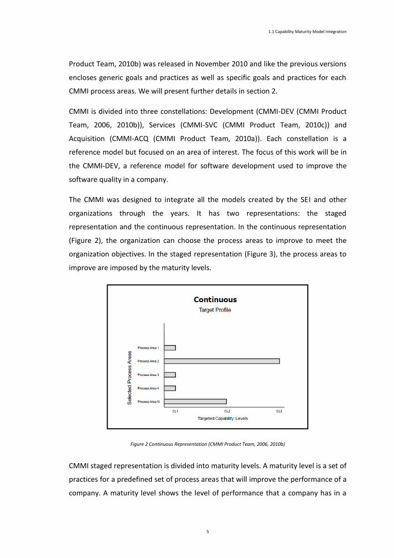
The CMMI was designed to integrate all the models created by the SEI and other
organizations through the years. It has two representations: the staged
representation and the continuous representation. In the continuous representation
(Figure 2), the organization can choose the process areas to improve to meet the
organization objectives. In the staged representation (Figure 3), the process areas to
improve are imposed by the maturity levels.
Figure 2 Continuous Representation (CMMI Product Team, 2006, 2010b)
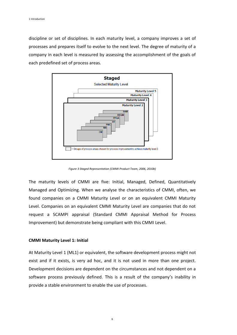
CMMI staged representation is divided into maturity levels. A maturity level is a set of
practices for a predefined set of process areas that will improve the performance of a
company. A maturity level shows the level of performance that a company has in a
1 Introduction
6
discipline or set of disciplines. In each maturity level, a company improves a set of
processes and prepares itself to evolve to the next level. The degree of maturity of a
company in each level is measured by assessing the accomplishment of the goals of
each predefined set of process areas.
Figure 3 Staged Representation (CMMI Product Team, 2006, 2010b)
The maturity levels of CMMI are five: Initial, Managed, Defined, Quantitatively
Managed and Optimizing. When we analyse the characteristics of CMMI, often, we
found companies on a CMMI Maturity Level or on an equivalent CMMI Maturity
Level. Companies on an equivalent CMMI Maturity Level are companies that do not
request a SCAMPI appraisal (Standard CMMI Appraisal Method for Process
Improvement) but demonstrate being compliant with this CMMI Level.
CMMI Maturity Level 1: Initial
At Maturity Level 1 (ML1) or equivalent, the software development process might not
exist and if it exists, is very ad hoc, and it is not used in more than one project.
Development decisions are dependent on the circumstances and not dependent on a
software process previously defined. This is a result of the company’s inability in
provide a stable environment to enable the use of processes.
1.1 Capability Maturity Model Integration
7
Although companies develop products, with success, all their budgets are spent, and
schedules are not achieved. Consequently, a company at this maturity level, most of
the time, when facing a crisis easily give up on the development process. Another
aspect of a company in this level is the slightly weak control over the development
process, and a lack of metrics to compare the success between projects.
CMMI Maturity Level 2: Managed
At Maturity Level 2 (ML2) or equivalent, projects developed by a company are
performed and managed according to documented plans. To allow this, important
project management process areas are implemented in this level.
The key process areas of this maturity level are:
• Configuration management: It is used to set and maintain the work
product’s integrity. This is done with configuration identification,
configuration control, configuration status accounting, and
configuration audits;
• Measurement and analysis: Used to develop a measurement capability
used to support the needs of the management information;
• Project monitoring and control: It provides the comprehension about a
project evolution, and this information can be used later on, to take
some actions in a project when performance diverges from the plan;
• Project planning: Is used to set and maintain the plans with the defined
project activities;
• Process and Product Quality Assurance: Is used to provide to the staff
and the management a view of the processes and associated works;
• Requirements management: Is used to manage the product (or
product components) requirements and verify if there is any
inconsistency between the requirements defined and the project plans
and product;
1 Introduction
8
• Supplier Agreement Management: Is used to manage the acquisition of
products from the company suppliers.
Through the implementation of these processes to plan projects, companies have the
advantage of repeating the success of a project in new projects. Another advantage
imposed by the use of these processes is the “guarantee” that the practices are kept
even in a crisis.
In this maturity level, we can infer that people involved in the project have the
necessary skills to produce the expected outputs. The stakeholders must be also
involved.
In some software departments, this level is the first to be implemented, but some
companies decide to go directly to the CMMI ML3 implementation (implement ML2
and ML3 at the same time) instead of implement only ML2 and implement ML3 in a
future project.
CMMI Maturity Level 3: Defined
At Maturity Level 3 (ML3) or equivalent, the processes are described with standards,
procedures, tools, and methods. The company improves those standard processes
over time. The project establishes their processes by adapting the standard processes
of the company following some tailoring guidelines. In other words, we can say that
the development process is standardized; it is looking for a common software
development standard across the entire organization and each project follows the
development standard or uses an approved and tailored version of the organization
process.
There is an important difference between ML3 and ML2. At ML2, the processes and
standards can be different from project to project, it can vary in each instance of the
process. At ML3, to execute a project, the standards and processes are adapted from
the organization set of processes (except if a change in the process is allowed by a
guideline), which is more coherent than in ML2.
The key process areas of this maturity level are:

1.1 Capability Maturity Model Integration
9
• Decision Analysis and Resolution: The main objective of this key
process area is to analyse other decisions than the decision that was
taken. This analysis is done with a formal evaluation process which
compares the alternatives with the established criteria;
• Integrated Project Management: It is used to set and maintain the
project and the participation of the company teams and stakeholders;
• Organizational Process Definition: Used to set and maintain a set of
processes and standards;
• Organizational Process Focus: Used to plan and implement the
company processes based on the comprehension of the weaknesses
and strengths of the processes;
• Organizational Training: Used to improve and develop the skills of the
personnel ? in order to allow them the efficient execution of their
roles;
• Product Integration: Used to take the product components and
assemble them in the final product, ensuring that the product is
functioning properly;
• Requirements Development: Used to analyse the customer needs to
produce the product and product components requirements;
• Risk Management: Used to identify the possibility of problems
occurring before they happen in order to plan some activities to handle
the risk. It is invoked whenever it is needed, during the lifecycle of the
project to allow the objectives achievement;
• Technical Solution: Used to design, develop and implement the
solution for the captured requirements;
• Validation: Used to show that the product (or product components)
accomplish its proposed used when placed in its environment;
1 Introduction
10
• Verification: Used to verify that the product accomplishes the specified
requirements.
CMMI Maturity Level 4: Quantitatively Managed
At Maturity Level 4 (ML4) or equivalent, quantitative objectives, based on the needs
of customers, users and developers are defined. Those objectives for quality and,
process performance, are used for evaluating and managing processes.
The process performance evaluation in ML3 and ML4 is different. At ML3, the
evaluation is made qualitatively. However, in ML4, the evaluation is made with
statistical and quantitative techniques.
The key process areas of this level are:
• Organizational Process Performance: Used to set and maintain the
comprehension of the company standard processes;
• Quantitative Project Management: Used to manage the processes of a
project in order to achieve the quality and the performance
established in the objectives.
CMMI Maturity Level 5: Optimizing
At Maturity Level 5 (ML5) or equivalent, a company keeps continually improving their
processes’ performance. This improvement is made with new and incremental
innovations in the processes and some technological improvements.
The company has already established their objectives for the quantitative process
improvement. Those objectives are revised continually in order to reflect the change
of the business. They are also used to manage the process improvement. At this level,
the defined processes and standard processes can be the object of an improvement.
The key process areas of this level are:
• Causal Analysis and Resolution: Used to identify the causes of defects
and problems and to take actions to prevent does errors in future;
1.1 Capability Maturity Model Integration
11
• Organizational Innovation and Deployment: Used to select and deploy
the improvements that will evolve the processes of the company.
1.2 Rational Unified Process
The Rational Unified Process (RUP) (Kruchten, 2003) is a software development
process framework, created by Rational Software (acquired by IBM in February 2003).
RUP was created in 1996 when Rational acquired the Objectory Process (Jacobsen,
1992).
According to RUP, a development process guides the efforts of the people involved in
a project, by providing them with a model of the steps to follow in order to create a
software product. RUP is based on a set of elements, which describes what is to be
produced, the necessary skills required and the explanation of how specific
development goals are to be achieved. These elements are the RUP artifacts, roles,
tasks and artifacts.
The artifacts are pieces of information that are produced, used or modified by a
process, under the responsibility of a particular role. They are the tangible work
products (documents, source code, UML model, etc.) created or used by the project,
establishing the process "what".
The roles are an element that defines a set of related skills, competencies, and
responsibilities. It defines who performs a given task and who is responsible for a
given artifact. One role can perform and be responsible for more than one artifact
and task.
A task describes a unit of work and each task is performed by a specific set of roles. It
usually affects one or a small number of artifacts. The tasks are usually expressed in
terms of creating or updating artifacts, such as models, classes, or plans. Each task
defines to each role a well-defined goal. It provides a complete step-by-step
explanation of accomplishing all the required work to achieve its goal. However, it
does not describe at what point of time a given work has to be done. It only describes
1 Introduction
12
the work that has to be done throughout the development lifecycle, which
contributes to the achievement of each task goal.
Activities are an RUP element that groups a set of other activities and tasks. They can
also refer to roles and artifacts. Activities define a breakdown structure of work or
predecessor relationships to other activities defining a flow presented in activity
diagrams.
Currently, the framework comprises over eighty articles, one hundred and fifty
activities and about forty roles.
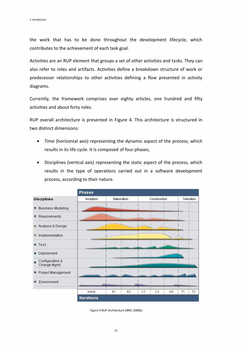
RUP overall architecture is presented in Figure 4. This architecture is structured in
two distinct dimensions:
Time (horizontal axis) representing the dynamic aspect of the process, which
results in its life cycle. It is composed of four phases;
Disciplines (vertical axis) representing the static aspect of the process, which
results in the type of operations carried out in a software development
process, according to their nature.
Figure 4 RUP Architecture (IBM, 2006b)

1.2 Rational Unified Process
13
The RUP phases are Inception, Elaboration, Construction and Transition. The
Inception main goal is to achieve agreement among all stakeholders on the lifecycle
objectives for the project. Its major concern is the definition of the project objectives,
scope and business model. This phase milestone is the Lifecycle Objectives Milestone,
which evaluates the fundamental viability of the project.
The Elaboration phase goals are the creation and validation of the software system
architecture, to capture the most significant requirements of the project, to estimate
the required resources for its implementation and assess risk. This phase milestone is
the Lifecycle Architecture Milestone, which establishes a managed baseline for the
architecture of the system.
The Construction phase main goal is the implementation of the software system,
according to the architecture defined in the Elaboration phase and ensuring its
progress until it is ready to be presented to the users. This phase milestone is the
Initial Operational Capability Milestone, in which is determined whether the product
is ready to be deployed into a beta-test environment or not.
The last phase is the Transition phase. Its main goal is the transition of the system
developed into production making it available to the end users. It also includes
conducting final beta testing, training of end users and preparation of maintenance
and support activities. This phase milestone is the Product Release Milestone.
RUP has nine disciplines: Business Modeling, Requirements, Analysis and Design,
Implementation, Test, Deployment Configuration and Change Management, Project
Management and Environment.
The Analysis and Design discipline include the activities needed to transform
Requirements artifacts into those that specify the design of the software that will be
developed in the project.
Business Modeling discipline includes activities, which describe business processes
and structure in order to better understand it and identify the most significant system
requirements.
The activities of Configuration and Change Management discipline are related to the
versions management and change request orders.
1 Introduction
14
The Deployment discipline is concerned with the installation package creation,
writing users documentation and other similar tasks.
The Environment discipline includes activities to adapt the process to the needs of
the project (or organization) and selection, introduction and support of the
development tools.
The Implementation discipline activities include tasks of creation and debugging
source code and unit tests.
Project Management discipline is focused on the project planning and monitoring activities.
The Requirements discipline activities explain how to elicit stakeholder requests and
transform them into requirements artefacts.
Finally, the Test discipline activities explain how to evaluate and assess the product
quality.
1.3 Goals and Research Strategy
The primary objective of this thesis is to provide a set of techniques that effectively
enable the wide adoption of the CMMI framework.
The goals of this thesis are:
To adopt and validate, using CMMI, a RUP configuration suited to small
software development teams that, without neglecting any critical function of
the software development process, may be easily implemented during a
project’s execution.
To identify the dependencies inside the CMMI-DEV framework of CMMI
process areas in order to understand the impact of implementing the maturity
level 2 simultaneously with some process areas from maturity level 3 in
companies seeking to configure CMMI according to their needs and as a way
to make CMMI more widely used.
1.3 Goals and Research Strategy
15
To propose an alignment of CMMI and RUP process frameworks, in order to
facilitate the CMMI compliance.
The research results will be validated using a set of real case studies. We want to
apply those results to a set of real case studies to demonstrate and validate our
proposal to solve the problem.
Research Methodology
The research methodology that we propose to use in order to validate the results
obtained in this research is Action Research (Avison et al., 1999; Baskerville, 1999; Siv,
1988; Villiers, 2005). Action research is a research type that involves researchers and
practitioners, who act together on a particular set of activities. This research
methodology is appropriate for examining the introduction of changes into
companies and project teams (Baskerville, 1999; Villiers, 2005). Action research is an
iterative process, can be performed in a cyclical way. The researcher, starts with the
problem identification, then researches a solution, examines the success of that
solution, and, if needed, repeats the steps (Baskerville, 1999; Villiers, 2005).
According to (Runeson & Höst, 2009; Runeson et al., 2012) action research can be
seen closely related to case study. The authors consider case studies as purely
observational and action research as being focused and involved in the changes. In
(Dittrich et al., 2008; Iversen et al., 2004) the authors express that in software process
improvement studies, the research method should be characterized as action
research. However, (Runeson & Höst, 2009; Runeson, et al., 2012) classify the action
research methodology, when used to study the effects of a change, as case study.
The fact that this research could be taken cyclically and the focus of our work is
software process improvement, was an important reason to adopt action research as
our research methodology. The capability of providing a solution to the problem,
analyse its impact and having the possibility to redefine and increment the solution
was another reason to adopt action research as research methodology for our work.
1 Introduction
16
1.4 Contributions
This thesis contributes with some tailored frameworks that allow the development of
software projects compliant with CMMI, in particular with CMMI ML2.
The main contributions are:
Validated RUP Reduced Model: The thesis validates the adopted RUP
Reduced Model using CMMI as assessment. The CMMI assesses the quality
achieved when the RUP Reduced Model is used.
CMMI Dependencies: The thesis defines a matrix with the dependencies
between all the CMMI Process Areas. The dependencies are presented by
CMMI Maturity Level and by Category.
CMMI-RUP Mapping: The thesis defines a CMMI-RUP mapping to help the
implementation of CMMI ML2 and ML3. A detailed mapping for CMMI ML2
was also defined.
1.5 Structure of this Document
This document is structured in seven chapters. All chapters are preceded by a chapter
cover that presents a table of contents aiming to facilitate immediate perception and
access to the main headlines of the chapter. Following the chapter cover, a small
summary of the chapter is presented, aiming to briefly summarize the main chapter
content. After the summary, the chapter starts with an introductory section and ends
with a concluding section; between those sections, come the sections relevant to the
chapter theme.
The seven chapters of this document and their main content are:
Chapter 1: Introduction. This chapter introduces the research frameworks, the goals
and research strategy, contribution, and document structure. The research
1.5 Structure of the Document
17
frameworks are the Capability Maturity Model Integration and the Rational Unified
Process.
Chapter 2: CMMI and RUP Research Efforts. This chapter introduces the research
efforts of Capability Maturity Model Integration and the Rational Unified Process in
the last years. It also presents existing synergies of combining CMMI and RUP.
Chapter 3: Tailoring the Rational Unified Process. This chapter presents the tailored
RUP configuration suited to small software development teams that will be adopted
in this work. It presents the tailored model roles and each role’s responsibilities.
Chapter 4: Dependencies inside the CMMI-DEV Framework. This chapter presents
the dependencies between all CMMI process areas. It presents the process areas,
specific practices and category dependencies.
Chapter 5: Mapping CMMI and RUP Process Frameworks. This chapter presents the
CMMI RUP compliance efforts. It presents the RUP task and activities that implement
the CMMI ML2 and ML3 process areas. A detailed mapping for CMMI ML2 into RUP
elements is also presented in this chapter.
Chapter 6: Case Studies Analysis. This chapter presents the results of the three case
studies implemented to validate the contributions of this thesis.
Chapter 7: Conclusion. This chapter presents the conclusions about the work
performed. It presents guidelines for future work and research in order to expand
and solidify knowledge about implementing CMMI when adopting RUP.

Chapter 2
CMMI and RUP Research Efforts
Chapter Contents
2 CMMI and RUP Research Efforts ...................................................................................................... 21
2.1 Introduction .............................................................................................................................. 21
2.2 CMMI ........................................................................................................................................ 22
2.3 RUP ........................................................................................................................................... 30
2.4 Conclusion ................................................................................................................................ 36

20
2
CMMI and RUP Research
Efforts
This chapter introduces the research efforts of Capability Maturity Model Integration
and the Rational Unified Process in recent years. It looks into the CMMI stage, and
continuous configuration to understand the differences between them. It also
presents the existing research efforts of adopting CMMI and RUP. This chapter also
includes the existing synergies of combining CMMI and RUP.
2.1 Introduction
In the recent years, software process improvement and, in particular, CMMI are being
widely used by several organizations to improve their product’s quality. CMM-DEV is
a process improvement approach for product and service development. The CMMI
main goal is to provide guidance for developing or improving organization
development processes. This framework is used to assess the process maturity of an
organization.
2. CMMI and RUP Research Efforts
22
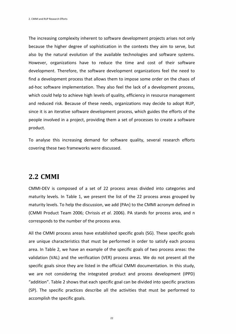
The increasing complexity inherent to software development projects arises not only
because the higher degree of sophistication in the contexts they aim to serve, but
also by the natural evolution of the available technologies and software systems.
However, organizations have to reduce the time and cost of their software
development. Therefore, the software development organizations feel the need to
find a development process that allows them to impose some order on the chaos of
ad-hoc software implementation. They also feel the lack of a development process,
which could help to achieve high levels of quality, efficiency in resource management
and reduced risk. Because of these needs, organizations may decide to adopt RUP,
since it is an iterative software development process, which guides the efforts of the
people involved in a project, providing them a set of processes to create a software
product.
To analyse this increasing demand for software quality, several research efforts
covering these two frameworks were discussed.
2.2 CMMI
CMMI-DEV is composed of a set of 22 process areas divided into categories and
maturity levels. In Table 1, we present the list of the 22 process areas grouped by
maturity levels. To help the discussion, we add {PAn} to the CMMI acronym defined in
(CMMI Product Team 2006; Chrissis et al. 2006). PA stands for process area, and n
corresponds to the number of the process area.
All the CMMI process areas have established specific goals (SG). These specific goals
are unique characteristics that must be performed in order to satisfy each process
area. In Table 2, we have an example of the specific goals of two process areas: the
validation (VAL) and the verification (VER) process areas. We do not present all the
specific goals since they are listed in the official CMMI documentation. In this study,
we are not considering the integrated product and process development (IPPD)
“addition”. Table 2 shows that each specific goal can be divided into specific practices
(SP). The specific practices describe all the activities that must be performed to
accomplish the specific goals.
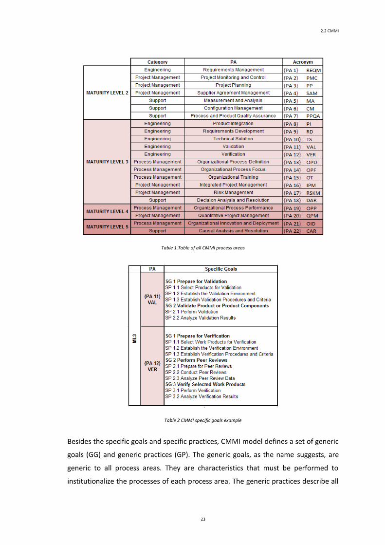
2.2 CMMI
23
Table 1.Table of all CMMI process areas
Table 2 CMMI specific goals example
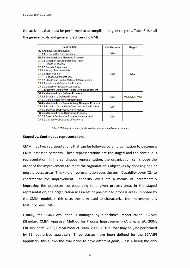
Besides the specific goals and specific practices, CMMI model defines a set of generic
goals (GG) and generic practices (GP). The generic goals, as the name suggests, are
generic to all process areas. They are characteristics that must be performed to
institutionalize the processes of each process area. The generic practices describe all
2. CMMI and RUP Research Efforts
24
the activities that must be performed to accomplish the generic goals. Table 3 lists all
the generic goals and generic practices of CMMI.
Table 3 CMMI generic goals for the continuous and staged representations
Staged vs. Continuous representations
CMMI has two representations that can be followed by an organization to become a
CMMI assessed company. These representations are the staged and the continuous
representation. In the continuous representation, the organization can choose the
order of the improvements to meet the organization’s objectives by choosing one or
more process areas. This kind of representation uses the term Capability Level (CL) to
characterize the improvement. Capability levels are a means of incrementally
improving the processes corresponding to a given process area. In the staged
representation, the organization uses a set of pre-defined process areas, imposed by
the CMMI model. In this case, the term used to characterize the improvement is
Maturity Level (ML).
Usually, the CMMI evaluation is managed by a technical report called SCAMPI
(Standard CMMI Appraisal Method for Process Improvement) (Ahern, et al., 2004;
Chrissis, et al., 2006; CMMI Product Team, 2006, 2010b) that may only be performed
by SEI authorized appraisers. Three classes have been defined for the SCAMPI
appraisals; this allows the evaluation to have different goals, Class A being the only

2.2 CMMI
25
appraisal methodology that offers a rating and covers the 40 requirements of the
evaluation procedure (Ahern, et al., 2004; Chrissis, et al., 2006; CMMI Product Team,
2006, 2010b).
Levels are used, in CMMI, to describe an evolutionary path recommended for an
organization that wants to improve the processes it uses to develop and maintain its
products and services. To achieve a capability level, the organization must satisfy all
the specific goals and generic goals for the process areas selected to be improved. To
achieve a maturity level the organization must satisfy all the specific and generic goals
for the pre-defined set of process areas imposed by the maturity level under
implementation. It is important to notice that in the continuous representation GG1
to GG5 are applied, but in the staged representation, only the GG2 and GG3 are
applied.
To illustrate the concepts of continuous and staged representation we will explain
how to achieve CL1 to CL3 for the {PA11} and how to achieve ML2 and ML3. To
support our approach, these capability and maturity levels are analysed in this paper
to establish a cross-ML|CL improvement roadmaps as stated by the formula (6) (in
section 4.2.4).
Introduction to Notation
Achieving CL1.{PA11} implies the execution of all the specific goals for {PA11} and the
GG1.
31
21
21
}11.{.2}11.{.1}11.{2
}11.{1}11.{}11.{1}11.{1
i i
i
PAiSPPAiSPPASG
PASGPASGiPAGGPACL (1)
The previous equation (1) expresses this effort. Executing all the specific goals for
{PA11} is the same as executing the entire specific practices for {PA11}.
To achieve CL2 to {PA11} we have to perform all the specific goals for {PA11} and the
GG2. In the next equation, we see that to achieve CL2.{PA11} we have to achieve
CL1.{PA11} and, at the same time, to execute all the specific goals for GG2.
2. CMMI and RUP Research Efforts
26
}11.{.2}11.{1
}11.{3}11.{1}11.{2
101 PAiGPPACL
PAGGPACLPACL
i
(2)
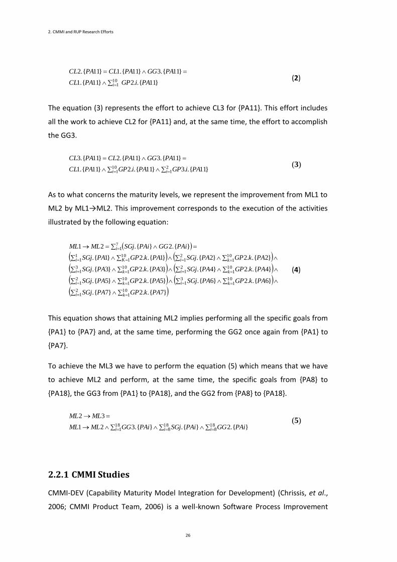
The equation (3) represents the effort to achieve CL3 for {PA11}. This effort includes
all the work to achieve CL2 for {PA11} and, at the same time, the effort to accomplish
the GG3.
10
12
1 }11.{.3}11.{.2}11.{1
}11.{3}11.{2}11.{3
i i PAiGPPAiGPPACL
PAGGPACLPACL (3)
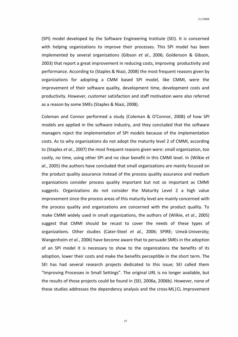
As to what concerns the maturity levels, we represent the improvement from ML1 to
ML2 by ML1→ML2. This improvement corresponds to the execution of the activities
illustrated by the following equation:
101
21
101
31
101
21
21
101
31
101
21
101
11
101
71
}7.{.2}7.{
}6.{.2}6.{}5.{.2}5.{
}4.{.2}4.{}3.{.2}3.{
}2.{.2}2.{}1.{.2}1.{
}.{2}.{21
ki
kiki
i ki k
i ki K
i
PAkGPPASGj
PAkGPPASGjPAkGPPASGj
PAkGPPASGjPAkGPPASGj
PAkGPPASGjPAkGPPASGj
PAiGGPAiSGjMLML
(4)
This equation shows that attaining ML2 implies performing all the specific goals from
{PA1} to {PA7} and, at the same time, performing the GG2 once again from {PA1} to
{PA7}.
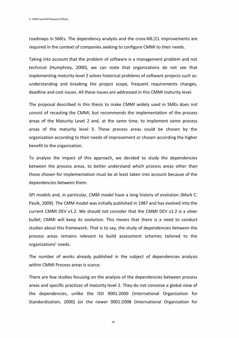
To achieve the ML3 we have to perform the equation (5) which means that we have
to achieve ML2 and perform, at the same time, the specific goals from {PA8} to
{PA18}, the GG3 from {PA1} to {PA18}, and the GG2 from {PA8} to {PA18}.
18
118
818
8 }.{2}.{}.{321
32
i i i PAiGGPAiSGjPAiGGMLML
MLML (5)
2.2.1 CMMI Studies
CMMI-DEV (Capability Maturity Model Integration for Development) (Chrissis, et al.,
2006; CMMI Product Team, 2006) is a well-known Software Process Improvement
2.2 CMMI
27
(SPI) model developed by the Software Engineering Institute (SEI). It is concerned
with helping organizations to improve their processes. This SPI model has been
implemented by several organizations (Gibson et al., 2006; Goldenson & Gibson,
2003) that report a great improvement in reducing costs, improving productivity and
performance. According to (Staples & Niazi, 2008) the most frequent reasons given by
organizations for adopting a CMM based SPI model, like CMMI, were the
improvement of their software quality, development time, development costs and
productivity. However, customer satisfaction and staff motivation were also referred
as a reason by some SMEs (Staples & Niazi, 2008).
Coleman and Connor performed a study (Coleman & O'Connor, 2008) of how SPI
models are applied in the software industry, and they concluded that the software
managers reject the implementation of SPI models because of the implementation
costs. As to why organizations do not adopt the maturity level 2 of CMMI, according
to (Staples et al., 2007) the most frequent reasons given were: small organization, too
costly, no time, using other SPI and no clear benefit in this CMMI level. In (Wilkie et
al., 2005) the authors have concluded that small organizations are mainly focused on
the product quality assurance instead of the process quality assurance and medium
organizations consider process quality important but not so important as CMMI
suggests. Organizations do not consider the Maturity Level 2 a high value
improvement since the process areas of this maturity level are mainly concerned with
the process quality and organizations are concerned with the product quality. To
make CMMI widely used in small organizations, the authors of (Wilkie, et al., 2005)
suggest that CMMI should be recast to cover the needs of these types of
organizations. Other studies (Cater-Steel et al., 2006; SPIRE; Umeå-University;
Wangenheim et al., 2006) have become aware that to persuade SMEs in the adoption
of an SPI model it is necessary to show to the organizations the benefits of its
adoption, lower their costs and make the benefits perceptible in the short term. The
SEI has had several research projects dedicated to this issue; SEI called them
“Improving Processes in Small Settings”. The original URL is no longer available, but
the results of those projects could be found in (SEI, 2006a, 2006b). However, none of
these studies addresses the dependency analysis and the cross-ML|CL improvement
2. CMMI and RUP Research Efforts
28
roadmaps in SMEs. The dependency analysis and the cross-ML|CL improvements are
required in the context of companies seeking to configure CMMI to their needs.
Taking into account that the problem of software is a management problem and not
technical (Humphrey, 2000), we can state that organizations do not see that
implementing maturity level 2 solves historical problems of software projects such as:
understanding and breaking the project scope, frequent requirements changes,
deadline and cost issues. All these issues are addressed in this CMMI maturity level.
The proposal described in this thesis to make CMMI widely used in SMEs does not
consist of recasting the CMMI, but recommends the implementation of the process
areas of the Maturity Level 2 and, at the same time, to implement some process
areas of the maturity level 3. These process areas could be chosen by the
organization according to their needs of improvement or chosen according the higher
benefit to the organization.
To analyse the impact of this approach, we decided to study the dependencies
between the process areas, to better understand which process areas other than
those chosen for implementation must be at least taken into account because of the
dependencies between them.
SPI models and, in particular, CMM model have a long history of evolution (Mark C.
Paulk, 2009). The CMM model was initially published in 1987 and has evolved into the
current CMMI DEV v1.2. We should not consider that the CMMI DEV v1.2 is a silver
bullet; CMMI will keep its evolution. This means that there is a need to conduct
studies about this framework. That is to say, the study of dependencies between the
process areas remains relevant to build assessment schemes tailored to the
organizations’ needs.
The number of works already published in the subject of dependencies analysis
within CMMI Process areas is scarce.
There are few studies focusing on the analysis of the dependencies between process
areas and specific practices of maturity level 2. They do not conceive a global view of
the dependencies, unlike the ISO 9001:2000 (International Organization for
Standardization, 2000) (or the newer 9001:2008 (International Organization for
2.2 CMMI
29
Standardization, 2008)) already do. One of the mandatory requirements from ISO
9001 is the clause 4.1b): "the organization shall [...] determine the sequence and
interaction of these processes".
In this work, our concern was the identification of which PAs have to be
implemented, or at least taken into consideration, when we implement a selected PA.
This PA identification was the principal reason for our dependencies study. However,
in the dependencies studies we have analysed (X. Chen et al., 2008; Mejia et al.,
2011; Villalón et al., 2008) the main reason to study CMMI dependencies were quite
different to ours.
In (Villalón, et al., 2008) the purpose of this work was to formalize an implementation
sequence of the CMMI-ACQ process areas of ML2. The dependencies analysis was
mandatory to achieve this goal. The authors start to identify the dependencies
between the PAs, then they analyse the dependencies in order to identify the
strongly connected components and finally the implementation sequence is
determined. To store the dependencies gathered after analysing the CMMI
documentation, the authors also use a matrix. However, and compared with our
work, we can see that our matrix contains more detailed information (see section
4.2). A similar conclusion can be taken when comparing the dependencies graphs.
The graphs in our work are more detailed than the graphs in this study. Although the
CMMI model analysed in both works is not the same (we analyse CMMI-DEV, in this
work CMMI-ACQ is analysed) we can see that our dependencies analyses are a little
more complex and complete.
In a recent work (Mejia, et al., 2011), the author’s purpose was to show the
establishment of the multi-model workflow of Solicitation and Supplier Agreements
Development (a CMMI-ACQ process area). To achieve this purpose, the authors had
to identify the process areas dependencies. The process areas dependencies
identification was performed by using the previous work (Villalón, et al., 2008). Since
both works use the same procedure to identify the process areas dependencies,
when comparing this study (Mejia, et al., 2011) with our work, in particular the
dependencies analysis section, we draw the same conclusions that we drew about
the previous work (Villalón, et al., 2008).
2. CMMI and RUP Research Efforts
30
The (X. Chen, et al., 2008) work analyses the dependencies between the SPs of each
PA. The major concern of this study was to identify the implementation order of each
SP. Since each SP belongs to a PA the authors derive a view of PA dependencies once
again with the main purpose of determining a sequence implementation. The source
of information used in this work was the description of each Specific Practice defined
in the CMMI documentation. Although the importance of the Specific Practice
information to identify the Process Areas dependencies, we consider that using this
information only as an input to the dependencies analysis in not enough. Therefore,
in our work we use other CMMI documentation sections (Related Process Areas
section, Relationships Among Process Areas chapter) as input to our dependencies
analysis to achieve a complete dependencies identification.
2.3 RUP
In recent years, several software process development frameworks have been
presented and implemented. One of the most well-known frameworks is the Rational
Unified Process (RUP) (Kruchten, 2003). This framework extends the Unified Process
(Jacobson et al., 1999) which in turn resulted from the integration and evolution of
older processes such as Rational Approach (Booch et al., 2007) and Objectory Process
(Jacobsen, 1992).
RUP is an iterative software development process, which assigns tasks and
responsibilities within an organization, to ensure the production of high quality
software (meeting the needs of their users in strict compliance with a predictable
timetable and budget). The RUP framework defines three basic elements: activities,
roles and artifacts. A set of activities, roles and artifacts need to be selected according
to the software project. Each project is performed by a group of actors having one or
more roles assigned. Each role participates in one or more activities and, as the result
of each activity, one or more artifact is produced. More than eighty artifacts, one
hundred and fifty activities and about forty roles compose this software development
process.
2.3 RUP
31
Although RUP is widely used, its structure lacks flexibility, and small enterprises that
adopt it have to face a very long development cycle and an "overload" of
documentation when using it mechanically (Barros Paes & Hirata, 2007; Jieshan &
Mingzhi, 2009). To overcome the excess of documentation and the high cost of a long
development cycle while, at the same time, maintaining quality (or at least not
reducing it too much), the software process must be tailored (by adding, merging
and/or deleting activities, roles and artifacts).
The need of tailoring a software process based on RUP, to decide what process
elements best suit the company or project, gave origin to a metamodel for process
tailoring compliant with RUP. This metamodel extends the RUP model by adding a set
of elements and relationships, and a set of well-formed rules used to guide the
process tailoring activities (Pereira et al., 2007).
Another set of research efforts (Hanssen et al., 2007; Hanssen et al., 2005a;
Westerheim & Hanssen, 2005) arose from the conclusions of a study presented in
(Hanssen et al., 2005b). They consider that leaving the responsibility of tailoring RUP
to each project context will take up too much time and too many resources; leading
them to give to the teams, before the project starts, an adapted version of RUP.
The work presented in (Hirsch, 2002) conveys a very pragmatic view about how RUP
can be configured to "speed up" its adoption (of course without missing any
procedural component considered essential) and thus prove the possibility of its
successful adoption in SME contexts. In this way, the author starts to perform a
significant simplification of the list of artifacts to produce, followed by a cost/benefit
analysis of each of the artifacts provided by the methodology.
Following a completely different approach, (Fernandes & Duarte, 2005) presents one
RUP configuration primarily oriented to organizations that develop software in a
process-oriented way, which may be appropriate for small entities that do not justify
the existence of a functional structure. The authors present a set of business
modelling artifacts whose production is considered essential. This paper also
highlights a possible need for internal restructuring in organizations that adopt the
RUP in order to overcome their difficulties in the composition of the set of roles
involved. In (Duarte et al., 2006) the authors continue this guideline, by further
2. CMMI and RUP Research Efforts
32
analysing the business modelling artifacts, and presenting a way to set up a
methodology that can incorporate procedural improvements to, thereby, enable
organizations that adopt RUP to get a better ranking on the CMM scale.
According to (Hesse, 2003), RUP is much too complex and sophisticated to be capable
of being implemented as a successful practice. It is alleged that RUP does not frame in
the best way the existing roles and that it does not adequately involve the users
during the transition phase. In (Henderson-Sellers et al., 2001; Henderson-Sellers et
al., 2000) another alternative approach is quantitatively compared with RUP
regarding the underlying concepts of both approaches as evidenced in their meta-
models. Also according to this article, RUP is considered lacking in the most
appropriate way to manage the human resources involved in their use.
The authors of (Chang, 2010; Gallagher & Brownsword, 2001; Manzoni & Price, 2003;
Marçal et al., 2007; Smith, 2000) present extensions to RUP in order to make it
compliant with CMM and CMMI, in particular with Maturity Levels 2 and 3. To extend
RUP, these works analyse the gaps between RUP and CMM or CMMI and then
propose activities and artifacts that will complement RUP to allow the compliance
with the other models.
Agile Methods (AM) are attempting to offer once again an answer to the impatient
business community asking for lighter weight and at the same time faster software
development processes (Abrahamsson et al., 2002). There are several examples of
AM: Crystal (Alistair, 2004), Agile Modeling (Alistair, 2004), Scrum (Ken, 2004) and
Extreme Programming (Kent, 2000). Some agile practices are used to change the
team roles, such as, for example, cross-functional and self-organizing teams
(Abrahamsson, et al., 2002; Marçal, et al., 2007). In the cross-functional teams
approach, the project team is divided into several small groups with the necessary
know-how to perform a set of roles. In the self-organizing team approach, followed
for instance by Scrum, the team is internally managed instead of being organized by
the project manager.
Other studies discuss the integration of RUP and Agile Methods (S. Ambler, 2002; S.
W. Ambler, 2001; Corporation, 2001; Kruchten, 2001). In those works, it is explained
that RUP and Agile Methods can be used in conjunction. According to the authors, it
2.3 RUP
33
is relatively easy to the RUP users to adopt AM practices by tailoring RUP. Some
studies show how Agile Methods can help organizations to accomplish CMM and
CMMI goals (M. C. Paulk, 2001; Reifer, 2003).
RUP, CMMI and Agile Methods can also be used together (Cintra & Price, 2006). In
this study, the authors present a requirements engineering process based on CMMI,
RUP and a set of agile principles and practices. They describe the components of the
proposed requirements engineering process and its compliance with CMMI.
Regarding the AM, the authors give some orientations on the usage of agile practices
in their requirements engineering process.
There are several other research efforts that propose the simplification or extension
of RUP, by adopting tailoring techniques. However, the majority of them does not
consider the organizational context existent in SMEs, namely from the roles’ point of
view. This chapter addresses this perspective.
The organizational world is ruled by reference models that influence and mould any
organization, whatever its activity, size or organizational culture. Regarding software
development organizations one must refer to reference models such as CMMI, SPICE
(ISO/IEC 15504:1998), ISO/IEC 9000, RUP, PMBOK, BABOK, PSP, ISO/IEC 9126,
SWEBOK (Manzoni & Price, 2003; Marchewka, 2009; Niazi et al., 2006), amongst
many others. Although these reference models act from many different perspectives
and in different sub-fields, their main purpose is to enhance the quality of the
developed software according to the final users’ needs (C.-Y. Chen & P. Pete, 2011).
Software is used on an everyday basis by organizations, supporting organizational
processes and, consequently, helping them become more flexible and able to change.
Software is ubiquitous and might be regarded as an organization’s DNA.
Using reference models to assess software quality is nowadays not only a minimum
requirement for an organization’s survival (Carvallo et al., 2008) but also a business
strategy (Kruchten, 2003). As stated before the present work is focused on two
reference models for software development processes: RUP (Kruchten, 2003) and
CMMI (CMMI Product Team, 2006, 2010b). RUP and CMMI are used for different
purposes the first being focused on the necessary activity flow and responsibilities,
and the other on determining the maturity of the process in use. RUP is a generic and
2. CMMI and RUP Research Efforts
34
configurable software development process framework that recommends activities in
order to convert the user’s needs into software by attributing responsibilities and
guidelines to the development team (IBM, 2003; Kruchten, 2003; Manzoni & Price,
2003). CMMI is a framework that provides principles and practices in order to achieve
a particular maturity level for the software development process improving these
processes (Ahern, et al., 2004; Chrissis, et al., 2006; CMMI Product Team, 2006,
2010b) and, therefore, enhancing software quality (Ahern, et al., 2004). RUP and
CMMI have a common goal: improving software quality and, therefore, increasing
customer satisfaction. They can be used together: with CMMI, we understand what
we have to do; with RUP, we realize how we have to do it.
A CMMI appraisal at ML2 guarantees that the organization’s processes are performed
and managed according to plan (Carvallo, et al., 2008). Although ML2 contains
engineering process areas (in CMMI V1.2) (Ahern, et al., 2004), the engineering
approach is only considered relevant at ML3 by several companies; due to the “level
2 syndrome” (P. Monteiro et al., 2009), they tend to skip ML2 and directly implement
ML3, which is considered a dangerous practice and has never been reported as
viable.
RUP enables the development team to accomplish an iterative transformation of the
user’s requirements into software that suits the stakeholder’s needs (IBM, 2003;
Kruchten, 2003; Manzoni & Price, 2003). RUP also provides guidelines for “what”,
“who” and “when” (Manzoni & Price, 2003), avoiding an ad-hoc approach (Kruchten,
2003) that is usually time consuming and costly (Carvallo, et al., 2008). RUP can be
represented in a bi-dimensional plan where time and process dynamics are shown on
the horizontal axis (presenting phases, iterations and milestones), and the vertical
axis is static and corresponds to activities, paths and roles (Kruchten, 2003). This
phased division reduces the risk and enhances the overall management of the project
(Marchewka, 2009).
Inception refers to the beginning of the project and has an estimated cost of 10%
(Kruchten, 2003). Its aim is to establish the scope and context of the project, identify
stakeholders and success criteria, estimate the cost and risks and describe the main
use cases in a consensual manner (Kruchten, 2003), for one or more iterations

2.3 RUP
35
(Manzoni & Price, 2003). By the end of this stage, one should be able to decide upon
the viability of the project. The case studies considered in this paper are framed
within the efforts of RUP Inception phase.
There are some drawbacks related to the RUP framework, such as the partial absence
of issues related to human resources management, communication management and
contract management (Manzoni & Price, 2003). In addition, the team may get lost in
details and excessive documentation when it is not able to determine valuable
artifacts for its project (Kruchten, 2003).
Table 4 Trimming RUP for Small Projects at Inception Phase (IBM, 2006a, 2006b)
2. CMMI and RUP Research Efforts
36
The use of RUP in small projects (IBM, 2006b) began in 2006 (Table 4). It is possible to
conclude that 36 mandatory artifacts (optional artifacts excluded) were reduced to 18
when it comes to small projects. This will be revisited further on for the CMMI-RUP
mapping analysis.
CMMI and RUP intersect each other with regards to software quality and hence
customer satisfaction. In addition, both models have been regularly updated, so they
do not become obsolete (Kruchten, 2003) and prevent an ad-hoc and chaotic
software development environment (Ahern, et al., 2004). While created by
independent entities, they both counted on the participation of experts from the
software industry and government (Ahern, et al., 2004). There are many reasons why
organizations should use these two frameworks: increased quality, productivity,
customer and partner satisfaction; lower costs and time consumed; and better team
communication (Ahern, et al., 2004; Carvallo, et al., 2008; Manzoni & Price, 2003).
CMMI-DEV may be used to evaluate an organization’s maturity whether it uses RUP
or not as a process model.
Since its origins, some process areas of CMMI are supported by RUP tasks, for
instance REQM, PP. These two process areas are the ones that require most effort
during Inception. Our study is mainly based on process areas of the CMMI ML2. Thus,
our study will allow the determination of the RUP practices that support these
process areas.
2.4 Conclusion
This chapter was dedicated to presenting and discuss related work in the field of
Capability Maturity Model Integration and Rational Unified Process.
We started by contextualizing the Capability Maturity Model Integration and
explaining the difference of following a Staged or a Continuous representation. We
also presented the research efforts to implement CMMI.
2.4 Conclusion
37
Similarly, we presented the RUP efforts to spread its adoption. This is achieved
through the tailoring of the RUP framework. RUP tailoring is a way to simplify or add
some missing elements to allow an easier adoption of this framework.
The adoption of CMMI and RUP simultaneously was also analysed. Some research
efforts are focused on making CMMI and RUP compliant, and suggest the extension
of RUP to become CMMI compliant. However, this solution is not suitable for small
and medium enterprises or small software development teams.

Chapter 3
Tailoring the Rational Unified Process
Chapter Contents
3 Tailoring the Rational Unified Process .............................................................................................. 41
3.1 Introduction .............................................................................................................................. 41
3.2 Step 1: Getting One RUP Base Model ........................................................................................ 42
3.3 Step 2: Instantiating to Get One RUP Reduced Model ............................................................... 57
3.4 Examples of Some Essential Roles ............................................................................................. 64
3.5 Conclusion ................................................................................................................................ 76

40
41
3
Tailoring the
Rational Unified Process
This chapter introduces a tailored model of the Rational Unified Process. This RUP
Reduced Model is a RUP configuration suited for small software development teams.
It defines a subset of RUP roles through the identification of the essential roles in a
software development project. The roles that compose this RUP roles subset are the
key participants needed to perform a software development project. The major
responsibilities of the roles that were not considered essential were assigned to the
tailored model roles.
3.1 Introduction
Now more than ever, the software development industry is being put to the test, as a
joint result of several stress factors. First, we have been witnessing a significant
increase in the complexity inherent in software development projects, due not only
to a higher degree of sophistication in the contexts they aim to serve, but also to the
natural evolution of the out-of-the-box features offered by the myriad of available
technologies and software systems. On the other hand, the ever growing importance
3 Tailoring the Rational Unified Process
42
of reducing time-to-market decreases the error margins, boosting the pressure
applied on the teams to deliver better software in less time.
In order to react to this scenery and tip the playing field in their favour, eastern
corporations have responded by establishing partnerships with software factories
based on developing countries and, in some cases, by creating their own off-shore
software development centres. However, though these might be good solutions for
large scale corporations and projects, they are inappropriate for some SMEs (Small
and Medium Enterprises) (Commission, 2005), given the usually short-term nature of
their projects and the considerably time-consuming specification requirements.
Since, SME’s urge for methodologies with the potential to help them cope with the
challenges faced, aroused by the low level of process standardization, RUP (Rational
Unified Process) (Kruchten, 2003) presents itself as a useful reference, given the
comprehensive set of roles proposed to structure software development teams.
However, there’s a lack of RUP configurations suited for micro (employing less than
10 people) and small companies (employing less than 50 people) (Commission, 2005).
This chapter aims to help small-scale organizations by introducing a RUP
configuration that, without neglecting any critical function of the software
development process, may easily be adopted during a project’s execution period. In
order to do so, the roles proposed by RUP were thoroughly reviewed in order to
select a much smaller subset of key participants that will inherit the duties of the
suppressed roles.
3.2 Step 1: Getting One RUP Base Model
Any company, regardless of its size, has an organic structure (more or less formal)
that identifies the roles of each employee, defines their areas of intervention and
establishes the responsibilities they have to assume, in order to achieve the
organization’s objectives. Thus, it is common to define organizational charts and
assigning specific positions to its employees.
RUP features nearly forty roles relevant to the software development process,
assigning to each one a particular set of specific responsibilities. However, after a
3.2 Step 1: Getting One RUP Base Model
43
brief analysis of the applicability of this set of roles in the context of an SME in the
software development sector we can conclude that the overwhelming majority of the
cases do not have a number of employees as high as the number of participants
expected. Therefore, even considering that in the context of a given project, a person
can be appointed to several roles, an excessive accumulation of responsibilities may
become too complex or demanding.
To be applicable in a simpler context, a software development process must be based
on the involvement of a lower number of players with different responsibilities.
However, a linear process to adapt the set of roles defined by RUP to the specific
players existing in a particular organization may find some difficulties resulting from
the characteristics of each role. In order to be more efficient, this process should take
place in three separate stages:
1. Reduce the number of relevant roles in the process of software
development, in order to make it easier to understand and, therefore, to
apply. Each of the roles proposed by RUP should be examined in order to
assess whether they are essential (and should be kept in its essence) or
not (and its tasks/responsibilities should be assigned to the remaining
essential roles);
2. Identify some restrictions to the accumulation of tasks/responsibilities by
the same person taking on the roles obtained in the previous step;
3. Propose one mapping between the previously identified essential RUP
roles and some of the canonical roles that one can usually find in an SME
of the software development sector. This mapping should not be
considered dogma; it should be reviewed in the context of each SME that
wishes to adopt it, according to its specific characteristics.
Next, the Base Model will be described, which corresponds to a RUP role
simplification tailored to medium-sized companies, which essentially seek a software
process that helps to design and implement solutions with high levels of quality
(perceived by the customer) and to deal with the complexity inherent in projects of
medium/high scale.
3 Tailoring the Rational Unified Process
44
However, it should be remembered that the reduction in the number of people
involved in the process of software development inevitably results in a higher
criticality of individual performances since it is necessary that each one assumes a
much larger range of responsibilities, usually without possessing more time or
resources to perform them. This not only increases the tension of each member of
the group, but also increases the probability of committing an error (or omission)
compared to what would happen if there were a greater number of people involved
in the process. Furthermore, it is not always easy to find the necessary skills in the
people who are available to perform the activities, previously assigned to the
suppressed roles.
To achieve the proposed goals, a detailed analysis of the RUP roles was conducted in
order to identify the roles to be considered essential, by satisfying at least one of the
following conditions:
• C1: If the role is suppressed the project will definitively fail;
• C2: The role demands a set of unique skills completely different from
those skills demanded by other roles;
• C3: The role imposes potential conflicts of interest when merged with
another role.
Taking into account the previous conditions, were suggested that the following roles
should be considered essential and thus integrated in the Base Model. For each role,
the conditions that are satisfied have been identified in order to consider this role as
essential. As an example, it can be seen that the System Analyst is an essential role
because it satisfies conditions C1 and C2.
System Analyst (C1, C2)
Scope management is vital to the success of any project, otherwise different opinions
between customers and suppliers are almost inevitable during the project execution.
Therefore, the participation of System Analysts is paramount from the beginning, to
identify and document with the utmost rigour the requirements (functional or non-
functional), in order to allow the supplier correctly estimate the effort involved in
performing the project.
3.2 Step 1: Getting One RUP Base Model
45
It is extremely important that the person who performs this role has appropriate
training, focusing mainly on two aspects: first, beyond basic knowledge in
management, it is desirable to understand in detail the client's business domain and
perceive the real motivations and relevance of the requirements presented by the
client; second, in order to develop his activities as appropriate and in accordance with
the best practices, it is desirable that the person has been trained and presents some
practice of requirements engineering techniques and methods (Software
Requirements in SWEBOK (Abran et al., 2004)).
User-Interface Designer (C2)
The scope of this role intervention in a project varies according to the nature of the
artifacts to be developed. Despite not being able to consider this role as a critical one,
it is a fact that its best performance mainly depends on a strong background in
specific areas of knowledge (such as the software ergonomics). This domain cannot
be considered widespread by the software engineering professionals.
Database Designer (C2)
Like the previous role, Database Designer is also considered essential to the process,
mainly due to the specificity of its knowledge. Although database design techniques
are mandatory in any computer science degree, usually the depth of the acquired
skills is insufficient. It is desirable that the performer of this role has (at least) the
following competencies: configuration and optimization of database engines;
advanced knowledge of setting up indexes, views, and constraints; advanced
knowledge on the implementation of triggers and stored procedures; and advanced
knowledge of standardization of data models.
Implementer (C1)
Regardless of how good the architecture and design of a software solution are it will
not be successful without the involvement of the Implementer (usually called
programmers), of the sub-systems and components that support the desired
functionalities.
3 Tailoring the Rational Unified Process
46
Integrator (C1, C2)
In SMEs, it is usual to find several Implementers involved in the project, each one
engaged with a specific set of tasks. To ensure that the work runs in a smooth and
efficient way, it is essential to have someone responsible for maintaining the
Implementers aware of the project context, for identifying the tasks to be undertaken
and for appointing the person responsible for each one. This person must also decide
how the individual tasks will be integrated and incorporated in the outcome of the
project. An example is the definition of the interfaces between the various sub-
systems. Besides these technical tasks, to allow the Project Manager to inform the
client when each feature is expected to be available, the Integrator is also responsible
for the initial definition of the critical dates of the project and for developing a plan
for the integration of the sub-systems.
This role requires the capability to monitor the activities of each Implementer to
ensure adoption of measures to minimize the impact in case of failure. Appropriate
training should include knowledge of human resource management, allowing the
encouragement and empowerment of their work. It is desirable that the person has
been trained and presents some practice in the SWEBOK knowledge areas of
software engineering management and software engineering process.
Software Architect (C1, C2)
The performer of this role is responsible for setting the technological foundation on
which the project implementation should be based. When this context is imposed by
the client, the Software Architect is responsible for estimating the technical risks
involved and how they might be mitigated. Other responsibilities are: the definition
of the skeleton of the system to be created; the characterization of the components
(defining the functions and boundaries of each one); the advising on the frameworks
that should be adopted. This role requires basic training in software architecture and
design (SWEBOK knowledge area of software design) and also the capability of
monitoring of the market trends to be aware of the most appropriate tools and
frameworks for achieving the goals of a given project.
3.2 Step 1: Getting One RUP Base Model
47
Process Engineer (C1, C2, C3)
The existence of a person mainly concerned with the management of the
development process is considered essential, his adaptation to the organizational
context and monitoring its implementation, in order to identify and implement
possible process improvements. This role requires a detailed knowledge of the
adopted development process (in this case RUP).
Project Manager (C1, C2)
This is an important role because it has the responsibility of assuming a global
overview of the project through a detailed interaction with the internal and external
participants. The Project Manager must create the conditions for the project to
achieve success, by ensuring the timeliness and the fulfilment of all the undertaken
commitments. To perform this role with quality it is essential to have training in
several areas such as basic knowledge in management; knowledge about the client’s
business domain; project management methodologies (like PMBOK (Project
Management Institute, 2008)) and negotiation skills.
Project Reviewer (C3)
This role need not be considered critical to the project success, and it does not
require any specific skills besides the ones required for any of the other roles.
However, it is important that the person responsible for this role present good
knowledge about the business domain. The person that performs this role should not
accumulate with another role within the project, due to particular responsibilities
related to verification and approval of several artifacts produced by other
participants, and concerned with conflict of interests.
Test Manager (C1, C3)
The existence of a role whose major responsibility is to ensure the product quality by
devising a plan for internal quality audits and coordinating its implementation is
3 Tailoring the Rational Unified Process
48
essential. This is another role that should not be accumulated with other roles in
particular with those roles related to the design and construction phase.
System Tester (C1, C3)
The implementation of the audit plan is performed by the system testers, which may
be entrusted with very different tasks, like the artifacts documental review and
testing behaviour. This is an essential role in the process.
Course Developer (C2)
The main concern of this role is the preparation and coordination of training. The
person with this role needs competencies in the area of didactics and pedagogy as
main skills to its execution.
System Administrator (C1, C2)
In software development projects, it is extremely important to have a person focused
on ensuring the satisfaction of the infrastructure needs, inherent to the process,
paying particular regard to the: personal computers of each element of the project
team, according to the needs of each one; servers that support the activities of the
team; servers that support the testing procedures and quality assessment; servers
that support the service provision to the outside. This person must have training in
the following skills: practice in the SWEBOK knowledge area of software
configuration; system administration; configuration and optimization of engine
databases; negotiation and contracting of IT services.
3.2.1 Mapping RUP Roles into Base Model Roles
Rather than the 39 original roles proposed by RUP, as seen in the previous section, it
is feasible to reduce to 13 the number of the essential roles to implement a software
process (that we call the Base Model) in the context of small development teams.
3.2 Step 1: Getting One RUP Base Model
49
However, the fact that none of the remaining 26 roles has been regarded as essential
to the process does not mean that their responsibilities may be discarded or that they
are not considered important for the effective and efficient implementation of the
process. Instead, it a mapping of the remaining roles into each one of roles previously
considered essential was proposed, according to the following guidelines:
• the appropriate profiles for performing both roles should be easily
compatible;
• the responsibilities of both roles should, whenever possible, find
themselves framed in the same (sub-) area of expertise;
• if the responsibilities of both roles are framed in distinct (sub-) areas of
knowledge, their accumulation by the same person will result in positive
synergies; if the elected recipient of a specific mapping is not in the best
position to accumulate it (either because he is already responsible for too
many roles or because the involved roles require a strong commitment),
another mapping should be tried; although not being the first choice, it
will garner better qualities to ensure its effective execution.
In Figure 5, the Base Model roles and the mappings between RUP roles and roles
considered essential in the Base Model are presented. Next will be presented the
mappings and the respective justification.
Business Reviewer, Requirements Reviewer and Management Reviewer maps into
Project Reviewer
The Project Reviewer is characterized by RUP as someone responsible for evaluating
the project artifacts at specific key moments with power and legitimacy, and, if
necessary, to suspend its execution. Therefore, this role can only be performed by
someone with a high level of responsibility and authority within the organization,
possibly even at the highest level since it is not unusual that managers of SMEs be
personally involved in supervising and monitoring projects. Thus, Project Reviewers
have the appropriate profile and, therefore, are able to evaluate the business
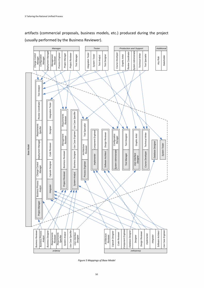
3 Tailoring the Rational Unified Process
50
artifacts (commercial proposals, business models, etc.) produced during the project
(usually performed by the Business Reviewer).
Figure 5 Mappings of Base Model
Co
nfig
ura
tion
Ma
na
ge
r
De
plo
yme
nt M
an
ag
er
Ma
na
ge
me
nt
Re
vie
we
r
Pro
cess
En
gin
ee
r
Te
st M
an
ag
er
Pro
ject
Ma
na
ge
r
Ch
an
ge
Co
ntr
ol
Ma
na
ge
r
Pro
ject
Re
vie
we
r
Manager
Sys
tem
Te
ste
r
Te
st A
na
lyst
Te
st D
esi
gn
er
Inte
gra
tion
Te
ste
r
Tester
Gra
ph
ic A
rtis
t
Re
vie
w C
oo
rdin
ato
r
Sys
tem
Ad
min
istr
ato
r
Te
chn
ica
l Write
r
To
ol S
pe
cia
list
Co
urs
e D
eve
lop
er
Production and Support
Sta
keh
old
er
An
y R
ole
Additional
Sys
tem
Te
ste
r
De
plo
yme
nt M
an
ag
er
Pro
ject
Ma
na
ge
rC
ha
ng
e C
on
tro
l
Ma
na
ge
rT
est
An
aly
stR
evi
ew
Co
ord
ina
tor
Bu
sin
ess
-Pro
cess
An
aly
st
Re
qu
ire
me
nts
Sp
eci
fier
Da
tab
ase
De
sig
ne
r
Pro
cess
En
gin
ee
rT
oo
l Sp
eci
alis
tA
rch
itect
ure
Re
vie
we
r
De
sig
n R
evi
ew
er
So
ftw
are
Arc
hite
ct
Co
nfig
ura
tion
Ma
na
ge
rS
yste
m A
dm
inis
tra
tor
Bu
sin
ess
De
sig
ne
rS
yste
m A
na
lyst
Use
Ca
se S
pe
cifie
rU
se C
ase
En
gin
ee
r
Te
st M
an
ag
er
Te
st D
esi
gn
er
Gra
ph
ic A
rtis
tU
ser-
Inte
rfa
ce
De
sig
ne
r
Te
chn
ica
l Write
rC
ou
rse
De
velo
pe
r
Co
mp
on
en
t E
ng
ine
er
Imp
lem
en
terBa
se M
od
el
Bu
sin
ess
-Pro
cess
An
aly
st
Bu
sin
ess
De
sig
ne
r
Re
qu
ire
me
nts
Re
vie
we
r
Re
qu
ire
me
nts
Sp
eci
fier
Use
r-In
terf
ace
De
sig
ne
r
Sys
tem
An
aly
st
Bu
sin
ess
Re
vie
we
r
Use
Ca
se S
pe
cifie
r
Analyst
Ca
psu
le D
esi
gn
er
Co
de
Re
vie
we
r
Co
mp
on
en
t E
ng
ine
er
Da
tab
ase
De
sig
ne
r
Imp
lem
en
ter
De
sig
ne
r
Arc
hite
ctu
re
Re
vie
we
r
De
sig
n R
evi
ew
er
Developer
Inte
gra
tor
So
ftw
are
Arc
hite
ct
Use
Ca
se E
ng
ine
er
Ma
na
ge
me
nt
Re
vie
we
rP
roje
ct R
evi
ew
er
Bu
sin
ess
Re
vie
we
r R
eq
uire
me
nts
Re
vie
we
r
Inte
gra
tion
Te
ste
rC
ap
sule
De
sig
ne
rC
od
e R
evi
ew
er
De
sig
ne
rIn
teg
rato
r
3.2 Step 1: Getting One RUP Base Model
51
The Requirements Reviewer has the responsibility to review formally the
requirements identified and incorporated into the use case model by the
Requirements Specifier. Therefore, it is essential that this person is knowledgeable of
the business domain, and he should also be familiar with the modelling techniques
used in the description of requirements. This role can be merged with the Project
Reviewer.
The Management Reviewer and the Project Reviewer are separated by a minor
difference since both are defined as responsible for review and evaluation of the
artifacts produced at certain key moments. Thus, and assuming what was previously
mentioned (that the Project Reviewer must be someone with some knowledge in the
business domain) the separation of these roles is not justified.
Business-Process Analyst, Requirements Specifier, Change Control Manager,
Deployment Manager, Test Analyst and Review Coordinator maps into Project
Manager
Since the Project Manager should be the person with greater proximity to the
customer, he may assume the responsibility of defining the business architecture and
describing their needs (in the form of business use cases), replacing the Business-
Process Analyst. This would ensure that the Project Manager knows in detail the
scope of the project, which allows him to deal appropriately with requests for
changes and carry out an effective monitoring of its implementation.
The Project Manager is also responsible for ensuring compliance with the scope and
minimizing the contract extensions that do not provide value to the organization.
However, the effectiveness of his intervention may suffer if he does not have a
thorough understanding of the agreed goals between the parties. For these reasons,
becoming responsible for the activities of the Requirements Specifier increases his
control over the project, by taking responsibility for listing and characterizing the
requirements, properly managing the customer expectations and ensuring they are
implemented by the project team.
In small-scale projects, it is normal that the Change Control Manager responsibilities
are assumed by the Project Manager or the Software Architect. However, despite it
3 Tailoring the Rational Unified Process
52
being essential that the Software Architect possesses deep and up-to-date knowledge
about the project, it is considered more important that the Project Manager ensures
an effective control over it; otherwise unrealistic expectations would be forced upon
the client. The Project Manager can also assume such responsibilities.
The Deployment Manager plans and coordinates the transition to the user’s
community of the products resulting from the development efforts. The success of
this type of activity mainly depends on the dialogue with the client and the planning
and communication skills of the person involved. The person performing this role
must work closely with the Project Manager, enough reason to merge these two
roles.
The reason to map the Test Analyst into the Project Manager arises from the fact that
the testing efforts must be aligned with the project context and the needs of end
users. The Project Manager is the person with more knowledge about the scope of
the project and about how the artifacts will be used. In dialogue with the Integrator
and the Test Designer, the Project Manager defines the scenarios that must be
tested. In addition, he can also be responsible for: monitoring the progress of the
testing process; analysing the results produced by the Test Designer and ensuring
that they are reported to the respective Integrators and that they are timely
corrected; evaluating the effectiveness of the testing process through the perceived
quality reported by the end users; facilitating the communication between test
Designers and Integrators.
Besides all the previous roles, the Project Manager is also considered the best role to
coordinate and control the activities inherent to role Review Coordinator.
Business Designer, Use Case Specifier, Use Case Engineer maps into System Analyst
The Business Designer is responsible for detailing the specification of the business
solution, producing artifacts that characterize the business entities involved, their
expectations and interactions. However, despite being focused on business, the
activity of this role is closer to the System Analyst because he is responsible for the
identification and documentation of the project requirements. Since, the System
3.2 Step 1: Getting One RUP Base Model
53
Analyst must also know the business domain, it is recommended merging it with the
Business Designer.
The Use Case Specifier role interacts closely with the end users and works together
with the System Analyst in the description of the use cases that embody the
identified requirements. Since this role is not defined as having their own specific
tasks but only acts as an assistant, he should be merged with the System Analyst.
The Use Case Engineer is responsible for ensuring that one or more embodiments of
the use cases represent, in a coherent and comprehensive way, the project’s
requirements. Therefore, and given the tasks performed by the System Analyst during
requirements elicitation, the merge with the Use Case Engineer activities were
considered a natural extension of his work.
Architecture Reviewer and Tool Specialist maps into Process Engineer
The Process Engineer role supports the project methodology and is responsible for
monitoring its implementation and making the necessary adjustments to optimize its
effectiveness.
The Architecture Reviewer is explicitly a technical role since he formally reviews the
architecture designed by the Software Architect, in order to validate the design
choices. It is important that the Architecture Reviewers have the necessary legitimacy
to point out mistakes or omissions. Apart from the obvious technical skills, it is
necessary to have good communication skills, enabling management of any conflicts
with the required sensitivity and delicacy. The Process Engineer is the person best
suited to accumulating the Architecture Reviewer responsibilities. By the nature of his
function, he has the necessary legitimacy to evaluate the performance of everyone
involved in the software development, on which he should have extensive
experience.
As to what concerns the Tool Specialist (which includes the identification of
stakeholders needs regarding the tools to assist/facilitate their work and selecting the
most appropriate applications to meet their needs) it has been decided to map his
responsibilities into the Process Engineer role.
3 Tailoring the Rational Unified Process
54
Capsule Designer, Code Reviewer, Designer and Integration Tester maps into
Integrator
The Capsule Designer has a profile similar to the Designer but more focused on the
accomplishment of the components performance requirements. Thus, given the
similarity of both profiles, the Integrator role assumes those responsibilities.
When coordinating the software development efforts of a team, the Integrator needs
a good level of technical expertise, which means that he should also be confident in
assuming the responsibilities of the Code Reviewer, by reviewing and auditing the
code source produced by the Implementers. This means, the Integrator must also
verify if each component has been implemented in accordance with his instructions
and detect potential problems.
The Designer must translate the architecture conceived by the Software Architect
into a coherent solution of components/modules/sub-systems to be implemented,
detailing responsibilities, operations and relations between them. Taking into account
that the Integrator is responsible for ensuring the successful integration of several
existing components, it makes sense that both roles should be performed by the
same person, maximizing the efforts involved in the design stage.
Considering that the primary responsibility of the Integration Tester is to perform the
integration tests, which are essential to verifying that the various components that
make up the solution are working well together, this role can be considered as a
natural extension of the activities conducted by the Integrator.
Component Engineer maps into Implementer
The Component Engineer is focused on the design of the internal structure of each
sub-system, particularly regarding operations, methods, attributes, relationships and
requirements of each design class. This role is strictly related with the Implementer’s
duties.
3.2 Step 1: Getting One RUP Base Model
55
Design Reviewer maps into Software Architect
The RUP methodology strongly suggests the existence of roles devoted to reviewing
artifacts written by third parties. Therefore, in order to maintain the independence, it
was suggested that the Software Architect accumulates the role of the Design
Reviewer.
Configuration Manager maps into System Administrator
It is suggested merging the responsibilities of the Configuration Manager and the
System Administrator. If the System Administrator is already responsible for
managing and providing the infrastructure used by the project team, it makes sense
also to perform the configuration management.
Test Designer maps into Test Manager
From the activities carried out by the Test Analyst emanates a set of test scenarios
that constitute a starting point for the work to be performed by the Test Designer,
who is responsible for coordinating the planning, design and implementation of the
necessary tests. However, these activities are a consequence of the responsibilities
that the literature attributes to the Test Manager, described as the main role
responsible for the success of the testing effort. Therefore, the Test Manager must
assume the Test Designer role.
Graphic Artist maps into User-Interface Designer
The performance of the Graphic Artist benefits from a refined aesthetic sensibility
and some experience in the use of image manipulation applications. However, since it
is common that these characteristics are also presented in the User-Interface
Designer, this role can also be responsible for meeting the project needs of image and
graphic communications.
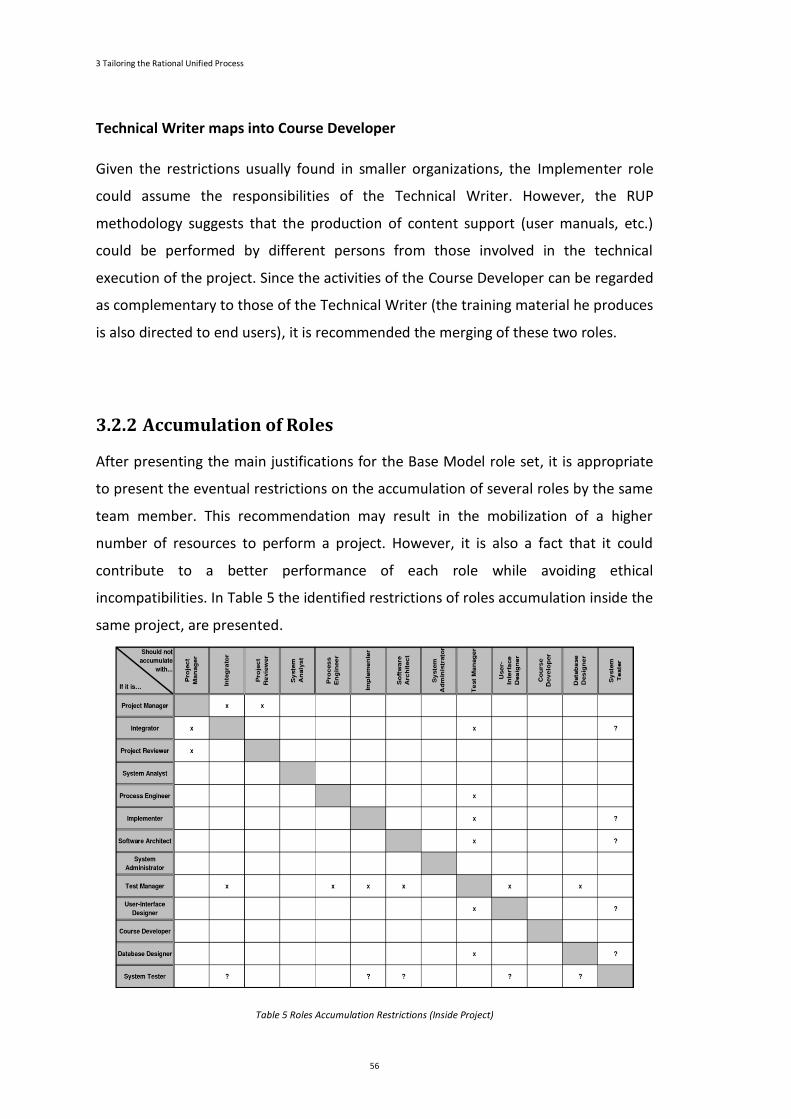
3 Tailoring the Rational Unified Process
56
Technical Writer maps into Course Developer
Given the restrictions usually found in smaller organizations, the Implementer role
could assume the responsibilities of the Technical Writer. However, the RUP
methodology suggests that the production of content support (user manuals, etc.)
could be performed by different persons from those involved in the technical
execution of the project. Since the activities of the Course Developer can be regarded
as complementary to those of the Technical Writer (the training material he produces
is also directed to end users), it is recommended the merging of these two roles.
3.2.2 Accumulation of Roles
After presenting the main justifications for the Base Model role set, it is appropriate
to present the eventual restrictions on the accumulation of several roles by the same
team member. This recommendation may result in the mobilization of a higher
number of resources to perform a project. However, it is also a fact that it could
contribute to a better performance of each role while avoiding ethical
incompatibilities. In Table 5 the identified restrictions of roles accumulation inside the
same project, are presented.
Table 5 Roles Accumulation Restrictions (Inside Project)
3.2 Step 1: Getting One RUP Base Model
57
The symbol “x” indicates an absolute restriction, which means that this accumulation
must be avoided. For instance, the integrator should not accumulate with the test
manager role because there are some ethical issues involved since the test manager
evaluates the artifacts produced under the integrator’s supervision. The symbol “?”
indicates a conditional restriction; i.e., an accumulation of roles that might be
possible if some regards are considered. As an example, the integrator presents one
conditional restriction to accumulate the system tester role because this
accumulation will only be possible in cases where the system tester tasks are not
performed within the same software development line under his coordination as
integrator.
3.3 Step 2: Instantiating to Get One RUP Reduced Model
Despite the effort already carried out to get a mapped sub-set of the original RUP
roles, the resulting base model is still difficult to be directly adopted by SMEs.
Therefore, it was considered appropriate to seek for a model involving a smaller
number of roles, giving up some specializations and promoting versatility. However,
to achieve this smaller set of roles, it is not appropriate to remove some roles and
randomly distribute their responsibilities among the remaining ones. In doing so, the
balance achieved with the base model would be deprecated in the resulting reduced
model, implying the failure of its execution due to the inability of one or more
individuals in performing their responsibilities. Instead, it is proposed to carry on the
simplification process according to the following guidelines:
1. identifying which roles previously considered “essential” may have lesser
prominence when compared with the others;
2. identifying the role in better conditions to assume the responsibilities of
each excluded participant, considering his profile;
3. validating if the proposed mappings will not unduly increase the
intervention area of the destination roles, to ensure that they have real
conditions to responsibly assume the responsibilities of the various tasks
to be performed.

3 Tailoring the Rational Unified Process
58
Figure 6 Comparative table between the base model and the reduced model
In the base model, some of the recommended mappings were between suppressed
roles into one role that in the reduced model described in this chapter will be
3.3 Step 2: Instantiating to Get One RUP Reduced Model
59
eliminated as an autonomous role. Therefore, it is crucial to define new mappings. In
addition, it is required not only to establish if the new mappings do not overload too
many the remaining roles, but also to ensure that they do not jeopardize the
independence that should exist between some role holders. In cases in which this
occurs, a new mapping should be proposed in order to balance the responsibilities
and workload of each essential role.
However, it is necessary to be conscious that the possible ease of applying the
reduced model when compared with the base model is usually achieved with a
quality reduction in the artifacts produced and/or a higher production cost (due to
the less experience/specialization of the people involved). Nevertheless, these
disadvantages can be regarded as a minor evil in organizational contexts, in which the
only alternative would be the use of a much more ad-hoc process without roles and
responsibilities formalization, which often results in a greater waste of resources and
inconsistency of actions.
In Figure 6, a comparative table between the base model and the reduced model is
presented. In this table, the level of simplification performed is visible in the reduced
model when compared with the base model. By analysing the table, we can see the
elimination (as autonomous roles) of the following essential roles: systems analyst,
software architect, user-interface designer, course developer and database designer.
The responsibilities of those roles were mapped into the remaining roles. Next, the
proposed mappings and the respective justification will be presented.
System Analyst, Business Designer and Use Case Specifier maps into Project
Manager
According to RUP, one of the Systems Analyst responsibilities is to coordinate the
requirements elicitation process in order to delimitate the project scope. However,
his intervention should be monitored and coordinated by the Project Manager since
he is the person closest to the client and that needs to be regularly informed about
the work in progress. Furthermore, in SMEs it is common to assign the Project
Manager role to a person with Software Engineering background (or even with
Requirements Engineering background). Therefore, it is possible to eliminate the

3 Tailoring the Rational Unified Process
60
System Analyst and at the same time impose a greater involvement of Project
Manager in the requirements elicitation process. In some cases, however, the System
Analyst can optionally be maintained in coexistence with the Project Manager.
The Business Designer intervention intends to improve the work of the Business-
Process Analyst, in order to characterize accurately and thoroughly a part of the client
organization. Therefore, it can be considered a supporting role to the Business-
Process Analyst activities. So, it was considered acceptable to map this role into the
Project Manager, naturally extending its intervention since he is also responsible for
the Business-Process Analyst tasks.
The Use Case Specifier role interacts closely with the end users and works together
with the System Analyst in the description of the use cases that embody the
identified requirements. Since this role is not defined as having its own specific tasks
but only acts as an assistant, he should follow the System Analyst and be merged with
the Project Manager.
Software Architect, Database Designer, Course Developer and Designer Reviewer
maps into Integrator
Although cyclical, the involvement of the Software Architect role in the development
process is meaningful in its beginning, namely in the draft and detail phases.
Therefore, in smaller organizations, it is difficult for these professionals to claim their
value since it is hard to make their work profitable in the subsequent project phases.
Usually the project size and/or complexity of such organizations do not justify the
need for the Software Architect role. Frequently it is not possible to provide these
professionals with the resources required (time for research, training, infrastructure,
etc.) to follow efficiently the emergence of relevant technological developments.
Therefore, maintaining this role will be artificial, resulting inevitably in its neglect
during the methodology operationalization. Thereby, the mapping of Software
Architect into the Integrator was proposed whenever necessary because he shares
the permanent need for technological updating and because the person chosen to
assume this role will be the most technically experienced inside the organization.
However, there are disadvantages associated with this simplification. One
3.3 Step 2: Instantiating to Get One RUP Reduced Model
61
disadvantage is possible loss of coherence in software architecture activities,
conducted either in separate projects or by different Integrators within the same
project, due to the absence of an external intervener to the project team that will act
as a reference and help each Integrator to find the best solution to the technological
issues. Other disadvantage is possible decrease in the capacity of organizational
learning and consequently of the innovative potential of the organization. These pros
and cons justify that the Software Architect role can optionally be maintained in
coexistence with the Project Manager.
The majority of the undergraduate degrees address technical training (more or less
advanced) on modelling and design of database models. However, some more
advanced concepts (like triggers, stored procedures, etc.) are only addressed in the
context of a specific database engine/ technology. Nevertheless, academic training
usually does not cover more advanced topics (such as administration, backup
strategies and data recovery, and optimization of the database engine/ technology).
Thus, organizations seeking to have this particular knowledge need to apply for
specialized training and usually associated with a specific database engine. However,
the majority of professionals in this area of knowledge possess the minimum
know-now required to perform this task. Therefore, it was considered that, under the
ongoing simplification effort, the Database Designer could be mapped into the
Integrator or the Implementer. However, the fact that the Integrator has a broader
view of the project compared to the Implementer can provide him the necessary
capability to design a data model that includes not only all the current needs but also
the improvements probably requested in the near future. Thus, the mapping of the
Database Designer into the Integrator is proposed.
The quality of the support material to the user training is extremely important for the
adoption of a new software application. In SMEs it is not necessary to maintain the
Course Developer as an essential role, since, although probably not have training in
the educational and training area, the Integrator shall have all the conditions to
produce support material to clarify the end-users about the use and operation of the
new software application. The support material produced shall be evaluated and
approved by another person in order to identify and correct possible gaps before its
delivery to the end-users.
3 Tailoring the Rational Unified Process
62
In the base model, the Design Reviewer was mapped into the Software Architect.
However, in the reduced model the Software Architect can optionally be considered a
“non-essential” role. Therefore, it is necessary to identify another role capable of
assuming the Design Reviewer responsibilities. The most reasonable solution is to
map this role into the Integrator, likewise to what was proposed to the Software
Architect.
User-Interface Designer, Designer, Graphics Artist and Technical Writer maps into
Implementer
Although undoubtedly very important to the success of a project, the attractiveness
and usability of the implemented user interfaces are issues that present lower
priority when compared with others (like time management and risk management).
This is why the User-Interface Designer is a natural candidate for mapping into
another role. Therefore, it is proposed that each Implementer will also assume this
role because they are usually involved in the implementation of user-interfaces, even
if they did not design those interfaces. Therefore, it is normal that within his
responsibilities and from the interaction with the User-Interface Designers, the
Implementers will learn the most important principles to observe, and consequently
replace the User-Interface Designers.
In the base model, the Designer role was mapped into the Integrator; assigning the
Designer Reviewer role to the Integrator results in a mismatch of responsibilities.
Obviously, this situation is highly undesirable since it will concentrate on the same
person the system design responsibility and evaluation of its correctness, destroying
the process independence. On the other hand, the reduced model maps several
additional roles to the Integrator, which means that there is a tendency for the
degradation of operational effectiveness, as a result of its huge range of
responsibilities. For the above reasons, in order to minimize these problems, it was
proposed to map the Designer into the Implementer, which will enable him to
participate actively in the system design.
The performance of the Graphic Artist benefits from an accurate aesthetic sensibility
and some experience in the use of image manipulation applications. However, since it
is common that these characteristics are also present in the User-Interface Designer,
3.3 Step 2: Instantiating to Get One RUP Reduced Model
63
this role can also be the responsible for meeting the project needs of image and
graphic communications. However, since the User-Interface Designer was mapped
into the Implementer, the Graphic Artist should also be mapped into this role.
By suppressing the Course Developer as an essential role, the Technical Writer can no
longer delegate to this role the production of support material and user manuals,
with the aim of releasing the implementers for development activities. However, in
small size teams, it is essential to enhance the knowledge of all participants.
Therefore, since the contents to be produced by the Technical Writer emanate mainly
from the implementation details controlled by the Implementers, it is recommended
to map the Technical Writer into this role.
Use Case Engineer maps into Test Manager
In the base model, the Use Case Engineer was mapped into the System Analyst role.
As already presented, in the reduced model the system analyst role can optionally be
mapped into the Project Manager role. Following the same rationale used to propose
the System Analyst mapping, the Use Case Engineer should be mapped into the
Project Manager role. However, the mapping of the Use Case Engineer role into the
test manager was proposed, basing this decision on the following reasons:
• the Test Manager gathers all the technical conditions required for the
proper performance of this role;
• as a result of the simplification process implicit in the reduced model, the
Project Manager will be responsible for ten different roles, combined with
the fact that he takes the major responsibility for the project, resulting in a
huge burden. Consequently, it is more realistic to consider the Test
Manager in better conditions to perform this role successfully;
• this mapping will increase the exhaustive knowledge of the requirements
by the Test Manager which will allow an easy test plan preparation, and
help the Project Manager to monitor the implementation.
3 Tailoring the Rational Unified Process
64
3.4 Examples of Some Essential Roles
In the previous section, the exercise of reducing the number of RUP roles existent in
the base model was carried out to make the process application plausible in the
context of an SME. Because of this, the mapping of roles established for the base
model into a more limited set of eight distinct roles was proposed. A thorough
description of RUP roles can be found in (Borges, 2008), where a first version of this
RUP configuration approach has been tried.
However, the operationalization of this synthesized set of roles lacks a detailed
definition of their responsibilities in order to delimit the area of intervention of each
participant. The characterization of the essential roles allows an easier selection of
the person with the most suitable profile for each role and also describes what is
expected from his intervention. However, since some of the organizations that are
interested in adopting this set of roles may not be familiar with RUP, they will be
presented free from RUP terminology.
Accordingly, in order to contextualize the interactions that take place between the
individuals, Figure 7 identifies the most common communication flows. The diagram
reveals that, within the same project, several lines of development may evolve
concurrently.
However, it is not possible to implement any project without the existence of a
significant interaction between the provider entity (in this case, a small software
development company) and the client entity consolidating multiple communications
flows. Nonetheless, the existence of several contingent communications among the
several internal and external stakeholders, the main link between the inside and
outside of the organization should be the Project Manager since only in this way can
the effective control over the project execution be ensured.
Next, two examples of role descriptions detailing their responsibilities will be
presented. Since the model that has been presented is the reduced model, the role
descriptions will describe the responsibilities of each role taking into account this
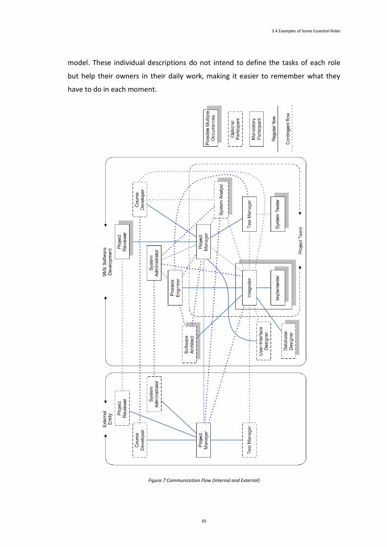
3.4 Examples of Some Essential Roles
65
model. These individual descriptions do not intend to define the tasks of each role
but help their owners in their daily work, making it easier to remember what they
have to do in each moment.
Figure 7 Communication Flow (Internal and External)
3 Tailoring the Rational Unified Process
66
Therefore, it is natural that some small duties do not appear in these descriptions,
mainly if it is not translated into a concrete task that has to be performed at a given
time. Despite presenting only two examples of role descriptions, all the individual
descriptions to the reduced model roles can be found in (Borges, 2008). These
descriptions will all be used in the case study. In this chapter, we have decided to
include descriptions of the roles Integrator and Implementer since they form a pair of
roles that work together and because they present a set of diverse responsibilities
which are noteworthy.
3.4.1 Integrator
This is certainly one of the most important roles of the proposed models. He is
responsible for coordinating the production activities of the artifacts needed to
achieve the objectives established by the Project Manager for a given system.
Thus, he must not only assign tasks to the Implementers, but also monitor
periodically their implementation in order to detect (as early as possible) any delays
or problems, which should be solved in cooperation with the Project Manager.
Additionally, he should cooperate with the Test Manager in order to provide all the
necessary assistance to the evaluation of the artifacts available within his
developments scope. The Integrator intervention is crucial to address two other
aspects: he should be able to overcome, by virtue of his experience, the eventual
inexistence of technical knowledge from the Project Manager to efficiently guide the
activities of the Implementers allocated to the project; the high number of
Implementers involved in the implementation of large projects would make it
virtually impossible for only one person (specifically the Project Manager) to
coordinate and control their work. It is possible to overcome this problem by
distributing several lines of development amongst the Implementers, each one
coordinated by a different Integrator. The activity of this role is primarily focused
within the organization, although it may need to interact directly with the outside
world, mainly in projects where the external entities have a quality control team. The
Integrators play an important role in the operationalization of the reusing strategy of
the organization source code since they are responsible for ensuring the reuse of the

3.4 Examples of Some Essential Roles
67
maximum number of existent components and to promote the creation of new
components for general purposes with potential relevance for future projects.
Integrator Responsibilities
The Integrator has about thirty responsibilities that he has to perform during the
software development process. Each responsibility was identified with Rn, where n is
the responsibility number. The responsibility numbers do not have any associated
order, the numbering is completely random. The Integrator responsibilities are
presented next.
R1: Ensuring compliance with all the defined objectives within his developments
scope.
R2: Coordinating, as efficiently and effectively as possible, the Implementers’ work,
assigning them tasks best suited to their profile and avoiding situations of idle
dependencies. In this sense, he should plan (as early as possible) the activities to
develop throughout each iteration, defining, timely and unequivocally, the
responsibility for implementing each task.
R3: Proposing to the Project Manager the number and duration of the iterations to
perform, their content and their artifacts, along with the technical characteristics of
each.
R4: Planning and executing the integration of the components implemented within
his developments scope, in order to produce the required version in each iteration.
R5: Planning and performing the appropriated integration tests for each produced
version, to ensure that the components included in the same version work properly
together.
R6: Proposing to the Process Engineer the content, format and location of the
internal documentation to be produced during the project.
R7: Ensuring timely production and publication of internal documentation considered
necessary.
3 Tailoring the Rational Unified Process
68
R8: Classifying each request of change received as simple (can be embedded in the
current iteration without prejudice the other features) or complex (involves reduction
of quality/functionality or increase of time or cost).
R9: Alerting (as early as possible) the Project Manager to situations where it is not
possible to achieve all the iteration objectives within the time scope.
R10: Proposing to the Process Engineer the list of components to reuse and non-
existent that can be created within his developments scope.
R11: Keeping, in collaboration with the Project Manager, a record of most meaningful
events related to the project development (for instance, external entities delays,
artifacts acceptance, etc.).
R12: Managing the communication between the Project Manager and the
Implementers that he coordinates.
R13: Evaluating, jointly with the Process Engineer, the performance of the
Implementers that he coordinates.
R14: Identifying and reporting to the Project Manager the project infrastructure
needs (for the several environments to be established).
R15: Executing certification/production requests and ensuring the creation of
supporting documentation.
R16: Ensuring project availability in the development environment.
R17: Being aware of the implementation details within his developments scope and
be capable to discuss with other stakeholders (internal or external).
R18: Periodically inspect the source code generated by the Implementers that he
coordinates and assess its quality and compliance with the defined policies for the
project.
R19: Standardizing, in accordance with the Process Engineer, the working methods of
his team, in particular regarding: tools (planning, coordination, document
management, development, modeling, logging, unit testing and bug tracking) to be
used; development methodologies and standards; package/components names;
3.4 Examples of Some Essential Roles
69
version control system location; code review process; integration build usage; error
codes; log file formats and categories to be used; configuration settings (file,
database, etc.) of each component within his developments scope.
R20: Ensuring that the Implementers that he coordinates adopt the best practices of
software development, namely: not to use hard-coded values, opting instead by its
inclusion in the component/application configuration; implementation of unit testing
in the components developed by them; frequently update (periods less than one
week), in the control version system, the source code of the components with which
he is involved.
R21: Following the execution of the internal (and possibly external) audit quality plan
on the artifacts produced within his developments scope.
R22: Periodically check the holiday calendar of the implementers that he coordinates.
R23: Ensuring the production, delivery and preservation of the required
documentation to support the certification/production execution process related to
his development scope.
R24: Notifying the Project Manager whenever he intends to make a holiday change.
R25: Evaluating the Implementers’ proposal for the interfaces of the main
components of the system.
R26: Proposing to the Process Engineer the major technical decisions, namely: list of
tools, application servers and database engines to be used; UML deployment diagram
that describes how the system is interconnected with all the other relevant systems;
UML component diagram describing the main components available in his
development scope and identifying the relationships between them.
R27: Identifying, estimating and reporting to the Project Manager and Process
Engineer the project’s technical risks resulting from the adopted architectural
decisions.
R28: Preparing the indexes, views, constraints, triggers and stored procedures
required to optimize the use of the data models supported by the database engines
for which he is responsible.

3 Tailoring the Rational Unified Process
70
R29: Identifying, in cooperation with the Project Manager, the content, format and
location of the supporting documentation to be produced during the project within
his developments scope.
R30: Designing the data model needed within his developments scope.
Integrator Cardinality
This role presents a mandatory nature and can even be performed simultaneously by
several individuals in the same project, making each one responsible for a different
line of development which, although possibly related to the other, has its own
objectives and evolves independently of the others.
Integrator critical performance
The Integrator performance is critical is some of his activities. He has to ensure the
goal’s achievement for each iteration and to ensure the motivation of the
implementers that he coordinates.
It also has, critically, the protection of the Implementers he coordinates from internal
and/or external pressures that may constrain their performance.
Another critical performance is the detection of non-feasible requirements or those
insufficiently described.
Integrator should avoid
In order to perform their activities without flaws, he has to avoid the influence of the
commercial decisions of the Project Manager. He should not oppose and/or reject to
cooperate with the Software Architect, and he should not antagonize the Test
Manager and/or not provide all the requested information.
Integrator tasks at the beginning of the project
At the beginning of the project, the Integrator should perform some of his defined
responsibilities. He has to perform the following responsibilities: R1, R6, R14, R19,
R22, R25, R26, R27, R29 and R30.

3.4 Examples of Some Essential Roles
71
Besides these responsibilities, at the beginning he has also to perform two other
tasks. He has to check if his holiday calendar is updated and, if not, report it to the
Project Manager. He has also to post, in a place defined by the organization, the
following information:
Number and duration of the iterations to be performed (and its content) in
agreement with the Project Manager;
Content, format and location of the internal documentation in agreement
with the Process Engineer;
Definition of working procedures in agreement with the Process Engineer;
Reference to the data models used within his developments scope;
Identification of all external stakeholders connected with the project, their
characterization and known contacts.
Integrator tasks at the beginning of each iteration
At the beginning of each iteration, the Integrator has to perform the followings
responsibilities: R4, R10, R18 and R21.
He has also to perform two other tasks at the beginning of an iteration. He has to
assign tasks to the Implementers that he coordinates and monitor the execution of
the moving on to certification/production of the previous iteration produced
artifacts.
Integrator tasks during each iteration
During each iteration, the Integrator has to execute the following defined
responsibilities: R1, R2, R8, R9, R11, R12, R15, R16, R17, R20 and R28. However, those
responsibilities are not the only tasks that he has to perform during the iteration. He
has also to execute the following tasks:
Promote weekly current status meetings (max. 30 min.) with the
Implementers that he coordinates;
3 Tailoring the Rational Unified Process
72
Validate the feasibility of the established requirements for the system under
his responsibility and, if this does not happen, help to find an alternative
considered viable and acceptable by the external entities;
Detect any new requirements arising from the implementation of the project
which, after being properly documented, should be provided to the Project
Manager (and if he exists, to the System Analyst);
Detect the established requirements that are not sufficiently described, and
report them to the Project Manager (and if existing, to the System Analyst);
Detect possible requirements which have not been made explicit by external
entities, and may be within their expectations or if they represent a business
opportunity that could be exploited and inform the Project Manager (and if
existing, to the System Analyst);
Whenever justified, notify the Project Manager and the Process Engineer
about the need to change the architecture within his developments scope
and/or technical risks identified and update the documentation affected by it;
Prepare the required contents to execute the training plan offered to end
users and to the several support teams (whether they are internal or
external).
Integrator tasks at the end of each iteration
At the end of each iteration, the Integrator has to perform the following assigned
tasks: R5, R13, R22 and R23.
However, his responsibilities at the end of an iteration should be complemented with
the following tasks:
Perform the integration of the components implemented within his
developments scope, in order to produce the required versions in each
iteration, ensuring the availability to moving on to certification/production;
Ensure that all developed components are updated in the version control
system;
3.4 Examples of Some Essential Roles
73
Ensure that the Database Designer and Implementers under his coordination
have fulfilled their activities for closing the iteration;
Review if the project infrastructure requirements are maintained in the next
iteration, and if not, notify the Project Manager about the necessary changes;
Evaluate, together with the Process Engineer, if the Implementers under his
coordination in the previous iteration are suitable and enough for his
development scope in the next iteration;
Ensure that the existing data about the allocation of his working time are
updated and available;
Review, with the Project Manager, the list of artifacts to produce in the next
iteration, along with the technical characteristics of each, which shall include:
o applications: new features (described in free text, documents or
diagrams), availability (online, outdoor installation, DVD, etc.),
communication and image requirements (graphical interfaces, etc.);
o documents: languages, addressed topics, format (Word, Excel, PDF,
etc.), communication and image requirements (using templates, etc.);
Check and notify the Project Manager about the need to make changes on
holiday dates that match with the next iteration;
Ensure the availability of the necessary training and support material;
Integrator tasks at the end of the project
The Integrator at the end of the project has to ensure that the Database Designer and
the Implementers under its coordination have fulfilled their project closing activities.
He has also to communicate to the Process Engineer the assessment of the technical
and behavioural skills of the Implementers that he coordinated throughout the
project, and to the Process Engineer the assessment of the components reused
within his developments scope, identifying any correction or change to accomplish.
3 Tailoring the Rational Unified Process
74
He should collaborate, coordinated by the Project Manager, on the execution of a
backup (at least in duplicate) of all relevant information (source code, artifacts, etc.)
associated with his developments scope.
Communicate to the Process Engineer the assessment of the software development
process used in the project, suggesting possible amendments or evolutions is also one
of the tasks that he has to perform at the end of the project.
3.4.2 Implementer
The tasks associated to this role are generic by their definition, because they vary
according to the requirements established for the components/systems to be
developed. However, in general terms, it can be said that commitment and
professional pride that should guide the intervention of Implementers will be
prevalent for the fulfilment of the external commitments assumed by the
organization and to obtain the desired quality levels for the artifacts implementers
help to produce.
Implementer Responsibilities
The Implementer has five responsibilities. Those responsibilities were also identified
similarly to what was done to the Integrator responsibilities. The Implementer
responsibilities are the following.
R1: Adopting best practices of software development.
R2: Performing with the utmost commitment and professional pride, the tasks
assigned by the Integrator that coordinates his work.
R3: Notifying the Integrator if he wants to make a change in the holiday dates.
R4: Alerting his Integrator as soon as possible when it is not possible to finish a task
within the deadline.
R5: Reporting weekly to his Integrator the time needed to complete his tasks.
3.4 Examples of Some Essential Roles
75
Implementer Cardinality
This role has a mandatory nature and can be performed simultaneously by several
individuals in the same project and divided into several lines of development.
Implementer critical performance
The Implementer performance is critical when he has to enable a possible corrective
action, as early as possible, in situations of potential non-compliance with the
objectives, and he has to create artifacts (applicational or not) with the quality level
desired by the organization.
Implementer should avoid
Not notifying the respective Integrator whenever he considers: not possessing the
adequate knowledge to perform a task assigned to him; the deadline that was
established to perform a given task is not enough.
Implementer tasks at the beginning of the project
At the beginning of the project, the Implementer has to check if his holiday calendar
is updated and if not, report it to his Integrator.
He has also to post, in a place defined by the organization, the identification of all
external stakeholders involved with the project, their characterization and contacts.
(This is a generic task, for several roles, ensuring that everyone shares information
about the stakeholders with whom they have contact in the project).
Implementer tasks at the beginning of each iteration
At the beginning of each iteration, the Implementer has only one task to perform:
request to the Integrator the tasks allocation.
Implementer tasks during each iteration
During each iteration, the Implementer has to perform four of his five responsibilities:
R1, R2, R3 and R4.
3 Tailoring the Rational Unified Process
76
Implementer tasks at the end of each iteration
At the end of each iteration, the Implementer has to ensure if the components source
code that he is involved with, is updated in the version control system and ensure if
the existing data about the allocation of his working time is updated and available.
He has also to check and notify the Integrator the need to make changes on the
holiday dates that match with the next iteration.
Implementer tasks at the end of the project
At the end of the project, the Implementer has to communicate to the Integrator the
assessment of the components reused, identifying any correction or change to be
accomplished. He has also to communicate to the Process Engineer the assessment of
the software development process used in the project, suggesting possible
amendments or evolutions.
3.5 Conclusion
Throughout this chapter, we have described that it is possible to configure the set of
RUP roles in order to significantly reduce its size and thus maximize its use by an SME.
Consequently, a reduction of the complexity embodied in the gathering of several
RUP roles around a set of individuals who should be considered essential was
introduced. Therefore, two models were proposed: (1) the base model; and (2) the
reduced model, a more pragmatic model, composed of eight distinct roles, which aim
is to allow an SME effectively control the progress of their projects and avoid overlap
and/or uncertainty of each individual scope of intervention.
Participants’ performance in the software development process carried out in an SME
is highly influenced by the limited range of human resources that usually accumulate
a new role with other responsibilities in an ongoing project or previous projects.
Therefore, it was decided to describe the responsibilities of each role, to help each
individual to know what is expected from him (by the exhaustive enumeration of his
responsibilities) and also identify the appropriate time to perform them (associating
3.5 Conclusion
77
each of his tasks to a phase in the project). Additionally, to reduce the margin of
error, a specific individual was named to verify/approve the completion of an action
item performed by another participant.

Chapter 4
Dependencies inside the CMMI-DEV Framework
Chapter Contents
4 Dependencies inside the CMMI-DEV Framework ............................................................................ 81
4.1 Introduction .............................................................................................................................. 81
4.2 Discovering Dependencies between CMMI-DEV Process Areas ................................................. 82
4.3 Discovering Dependencies between CMMI-DEV Categories ...................................................... 93
4.4 Updating Dependency Analysis for CMMI-DEV v1.3 .................................................................109
4.5 Conclusion ...............................................................................................................................110

80
4
Dependencies inside the
CMMI-DEV Framework
This chapter presents the dependencies of CMMI-DEV framework. The CMMI process
areas have several dependencies between them. The process areas dependencies are
not explicitly defined in the CMMI official documentation. The identified
dependencies are spread by several sections and presented in different formats along
the official documentation. In this chapter, it is also presented how to assess a merge
of staged and continuous representations.
4.1 Introduction
Software Process Improvement (SPI) and, in particular, CMMI are being widely used
by several organizations to improve their products´ quality. However, Small and
Medium Enterprises (SMEs) are reluctant to adopt CMMI and, in particular, Maturity
Level 2 of CMMI due to this Maturity Level being considered too expensive to achieve
and without clear benefits to the companies. The purpose of this chapter is to
propose a solution to increase SMEs interest in CMMI and in particular in Maturity
Level 2 of CMMI. This solution consists of the implementation in advance of some
Process Areas of Maturity Level 3, considered as a benefit by the organization, when
4 Dependencies inside the CMMI-DEV Framework
82
implementing the Process Areas of Maturity Level 2 of CMMI. This chapter starts by
analysing the dependencies among all the Process Areas of CMMI and between all
the Process Areas of each Maturity Level of CMMI. Using the Validation and the
Verification Process Areas from Maturity Level 3 of CMMI the chapter analyses the
impact on the dependencies of Maturity Level 2 when introduced some process areas
of Maturity Level 3 in the CMMI implementation to illustrate the additional effort
needed in the implementation.
4.2 Discovering Dependencies between CMMI-DEV Process Areas
Looking into the official CMMI documentation (CMMI Product Team 2006; Chrissis et
al. 2006) we cannot have a global view of the dependencies between all the process
areas. Initially, we identify the dependencies by reading the “related process areas”
section of each process area. Subsequently, we complemented this study by looking
at the SG descriptions of each process area to identify another set of dependencies
between the process areas.
To obtain the complete list of all the dependencies between all the process areas we
started to analyse the “related process areas” section for all the process. Then, we
decided to create a matrix (that contains the information of all the dependencies) and
a set of graphs (that graphically represents the information stored in the matrix). The
matrix rows represent the source process areas and the columns represent the
destination process areas, in the dependency analysis perspective. To complement
this study we look at the SG descriptions to identify new dependencies, introduce
these new dependencies into the previous matrix and add it to the graphs.
4.2.1 Elementary Dependency Analysis
The initial effort to identify the process areas dependencies was performed by
studying the elementary dependency analysis of a particular process area. This
elementary analysis is called PAn-centric dependency analysis (n is the number of the
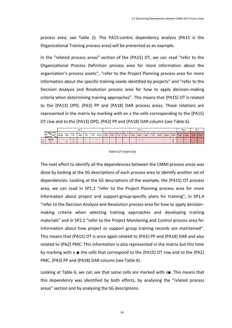
4.2 Discovering Dependencies between CMMI-DEV Process Areas
83
process area; see Table 1). The PA15-centric dependency analysis (PA15 is the
Organizational Training process area) will be presented as an example.
In the “related process areas” section of the {PA15} OT, we can read “refer to the
Organizational Process Definition process area for more information about the
organization’s process assets”, “refer to the Project Planning process area for more
information about the specific training needs identified by projects” and “refer to the
Decision Analysis and Resolution process area for how to apply decision-making
criteria when determining training approaches”. This means that {PA15} OT is related
to the {PA13} OPD, {PA3} PP and {PA18} DAR process areas. Those relations are
represented in the matrix by marking with an x the cells corresponding to the {PA15}
OT row and to the {PA13} OPD, {PA3} PP and {PA18} DAR column (see Table 6).
Table 6 OT matrix line
The next effort to identify all the dependencies between the CMMI process areas was
done by looking at the SG descriptions of each process area to identify another set of
dependencies. Looking at the SG descriptions of the example, the {PA15} OT process
area, we can read in SP1.2 “refer to the Project Planning process area for more
information about project and support-group-specific plans for training”, in SP1.4
“refer to the Decision Analysis and Resolution process area for how to apply decision-
making criteria when selecting training approaches and developing training
materials” and in SP2.2 “refer to the Project Monitoring and Control process area for
information about how project or support group training records are maintained”.
This means that {PA15} OT is once again related to {PA3} PP and {PA18} DAR and also
related to {PA2} PMC. This information is also represented in the matrix but this time
by marking with a ■ the cells that correspond to the {PA15} OT row and to the {PA2}
PMC, {PA3} PP and {PA18} DAR column (see Table 6).
Looking at Table 6, we can see that some cells are marked with x■. This means that
this dependency was identified by both efforts, by analysing the “related process
areas” section and by analysing the SG descriptions.
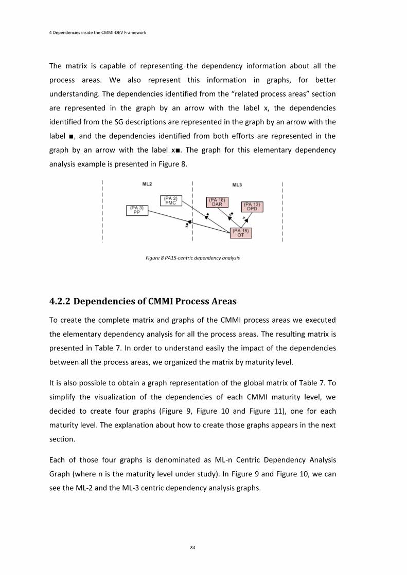
4 Dependencies inside the CMMI-DEV Framework
84
The matrix is capable of representing the dependency information about all the
process areas. We also represent this information in graphs, for better
understanding. The dependencies identified from the “related process areas” section
are represented in the graph by an arrow with the label x, the dependencies
identified from the SG descriptions are represented in the graph by an arrow with the
label ■, and the dependencies identified from both efforts are represented in the
graph by an arrow with the label x■. The graph for this elementary dependency
analysis example is presented in Figure 8.
Figure 8 PA15-centric dependency analysis
4.2.2 Dependencies of CMMI Process Areas
To create the complete matrix and graphs of the CMMI process areas we executed
the elementary dependency analysis for all the process areas. The resulting matrix is
presented in Table 7. In order to understand easily the impact of the dependencies
between all the process areas, we organized the matrix by maturity level.
It is also possible to obtain a graph representation of the global matrix of Table 7. To
simplify the visualization of the dependencies of each CMMI maturity level, we
decided to create four graphs (Figure 9, Figure 10 and Figure 11), one for each
maturity level. The explanation about how to create those graphs appears in the next
section.
Each of those four graphs is denominated as ML-n Centric Dependency Analysis
Graph (where n is the maturity level under study). In Figure 9 and Figure 10, we can
see the ML-2 and the ML-3 centric dependency analysis graphs.
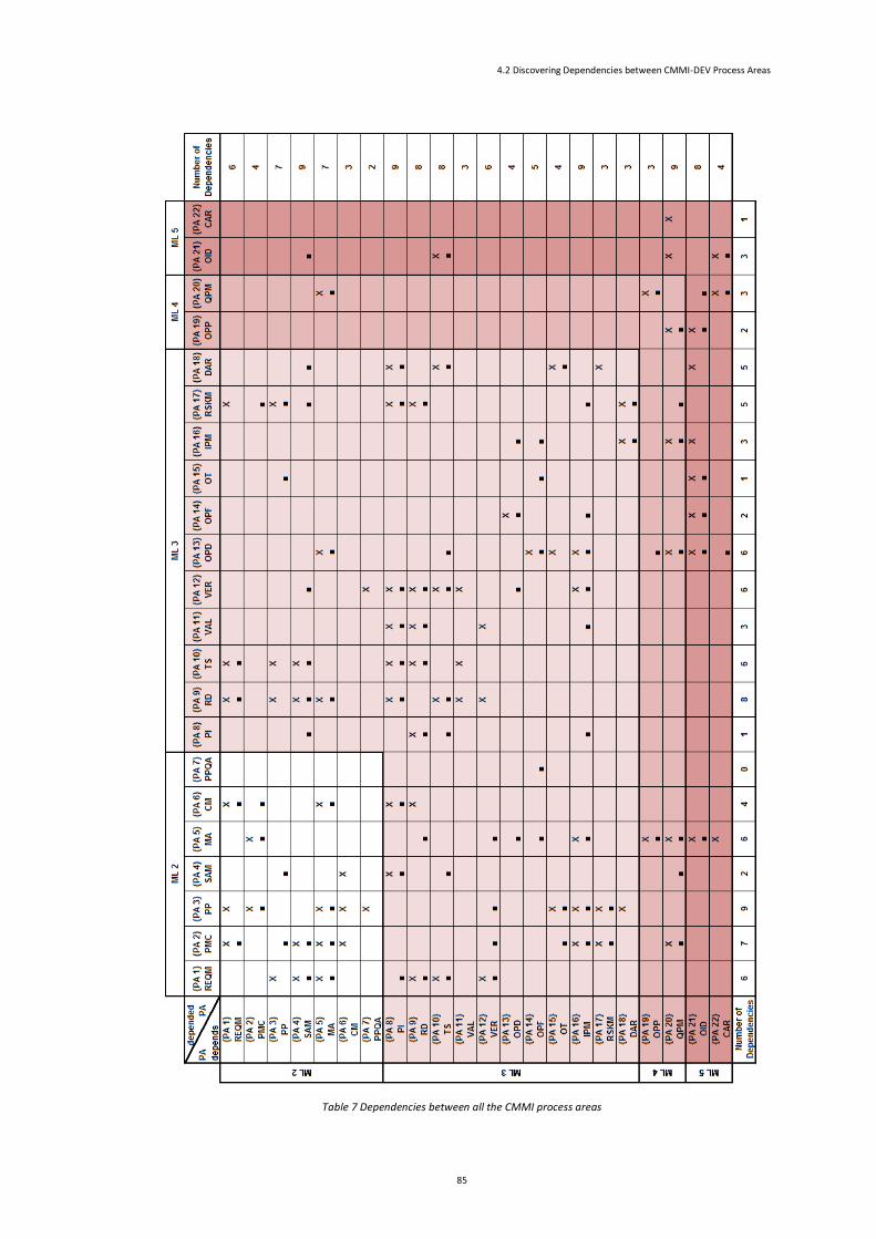
4.2 Discovering Dependencies between CMMI-DEV Process Areas
85
Table 7 Dependencies between all the CMMI process areas
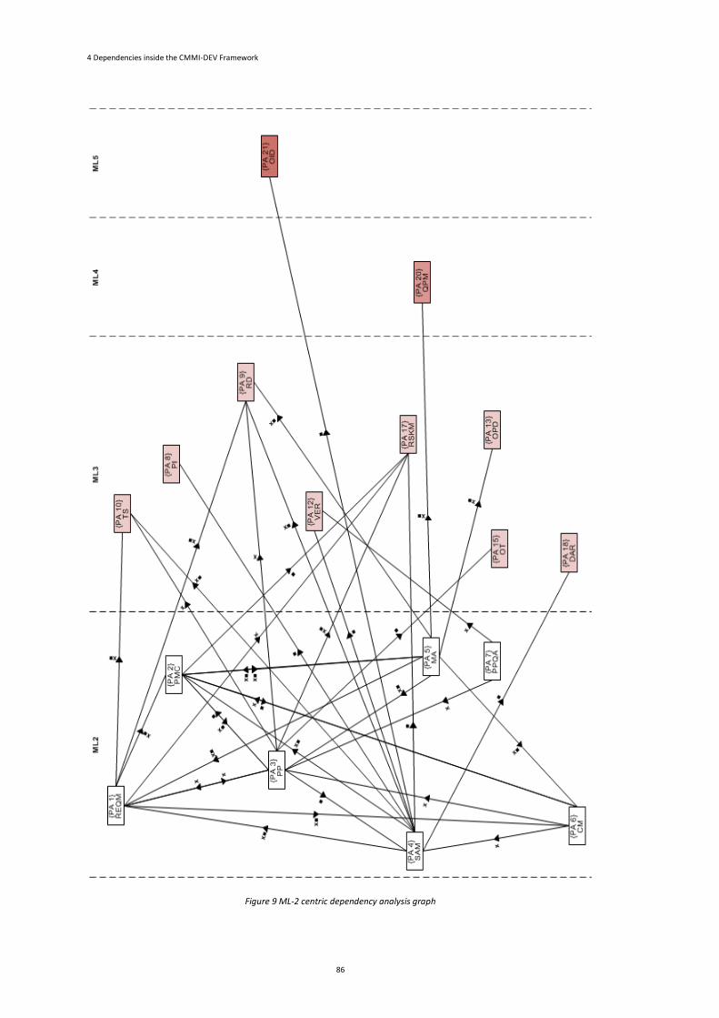
4 Dependencies inside the CMMI-DEV Framework
86
Figure 9 ML-2 centric dependency analysis graph
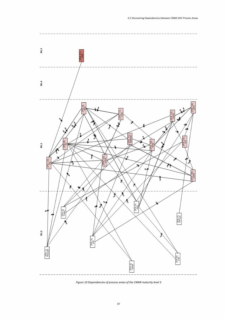
4.2 Discovering Dependencies between CMMI-DEV Process Areas
87
Figure 10 Dependencies of process areas of the CMMI maturity level 3
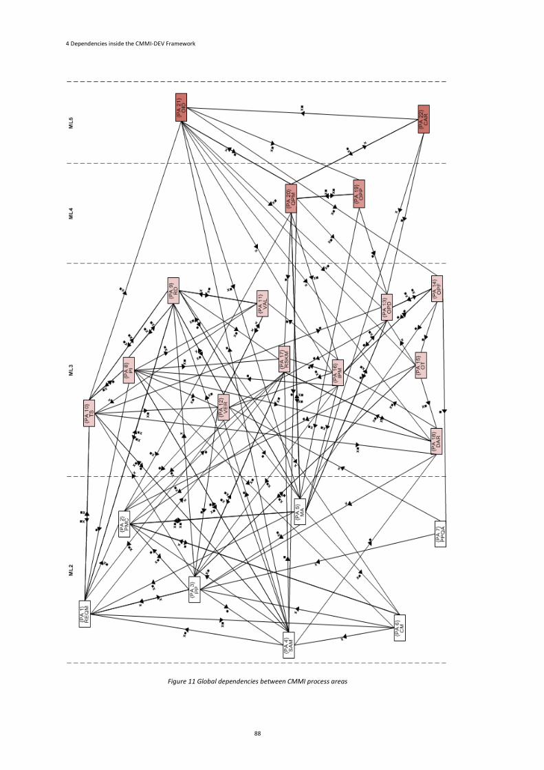
4 Dependencies inside the CMMI-DEV Framework
88
Figure 11 Global dependencies between CMMI process areas
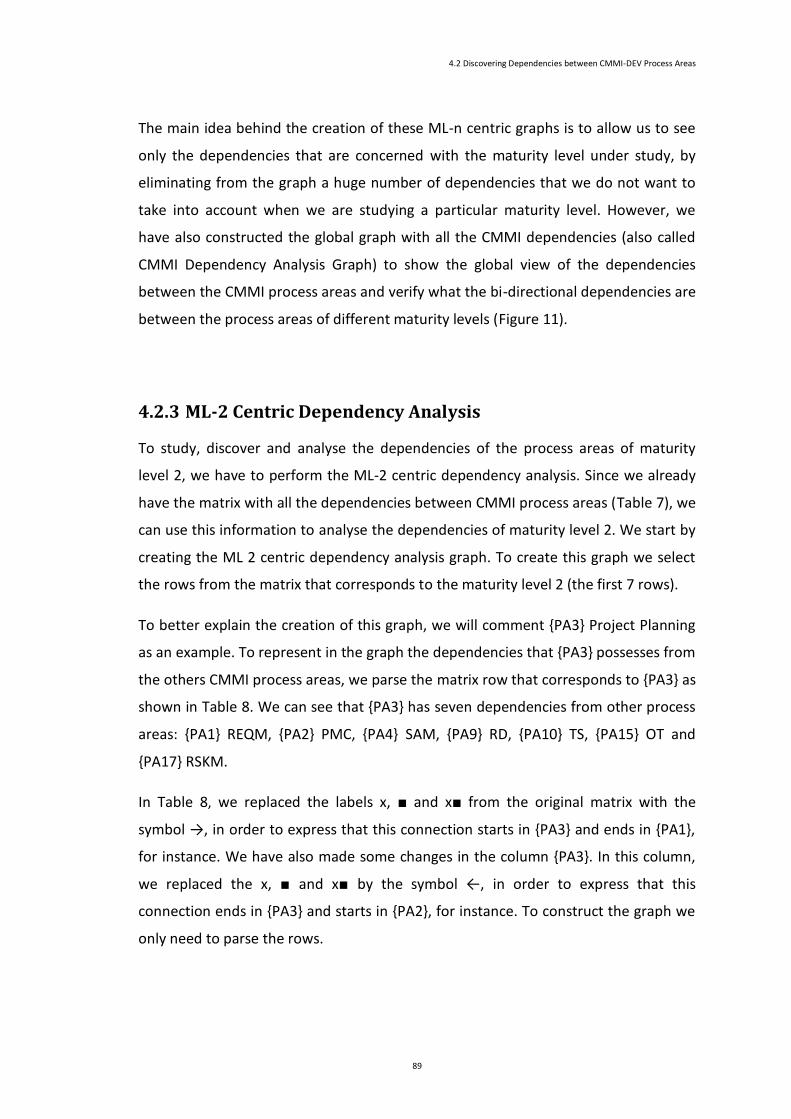
4.2 Discovering Dependencies between CMMI-DEV Process Areas
89
The main idea behind the creation of these ML-n centric graphs is to allow us to see
only the dependencies that are concerned with the maturity level under study, by
eliminating from the graph a huge number of dependencies that we do not want to
take into account when we are studying a particular maturity level. However, we
have also constructed the global graph with all the CMMI dependencies (also called
CMMI Dependency Analysis Graph) to show the global view of the dependencies
between the CMMI process areas and verify what the bi-directional dependencies are
between the process areas of different maturity levels (Figure 11).
4.2.3 ML-2 Centric Dependency Analysis
To study, discover and analyse the dependencies of the process areas of maturity
level 2, we have to perform the ML-2 centric dependency analysis. Since we already
have the matrix with all the dependencies between CMMI process areas (Table 7), we
can use this information to analyse the dependencies of maturity level 2. We start by
creating the ML 2 centric dependency analysis graph. To create this graph we select
the rows from the matrix that corresponds to the maturity level 2 (the first 7 rows).
To better explain the creation of this graph, we will comment {PA3} Project Planning
as an example. To represent in the graph the dependencies that {PA3} possesses from
the others CMMI process areas, we parse the matrix row that corresponds to {PA3} as
shown in Table 8. We can see that {PA3} has seven dependencies from other process
areas: {PA1} REQM, {PA2} PMC, {PA4} SAM, {PA9} RD, {PA10} TS, {PA15} OT and
{PA17} RSKM.
In Table 8, we replaced the labels x, ■ and x■ from the original matrix with the
symbol →, in order to express that this connection starts in {PA3} and ends in {PA1},
for instance. We have also made some changes in the column {PA3}. In this column,
we replaced the x, ■ and x■ by the symbol ←, in order to express that this
connection ends in {PA3} and starts in {PA2}, for instance. To construct the graph we
only need to parse the rows.
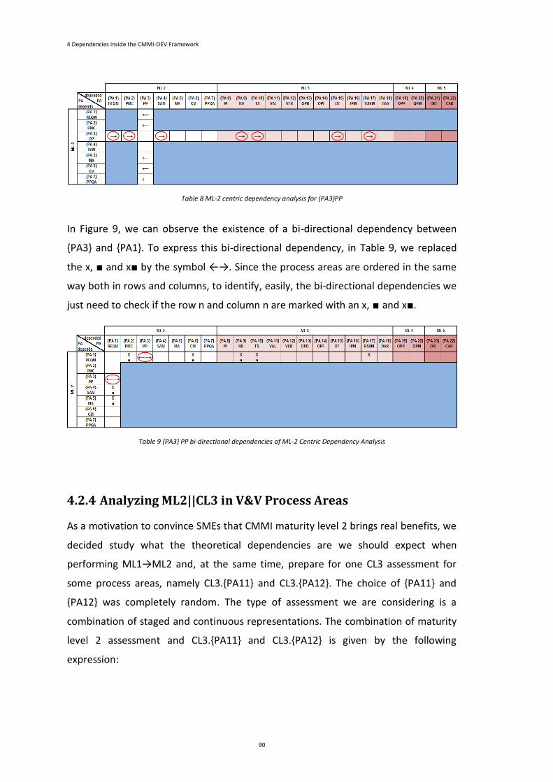
4 Dependencies inside the CMMI-DEV Framework
90
Table 8 ML-2 centric dependency analysis for {PA3}PP
In Figure 9, we can observe the existence of a bi-directional dependency between
{PA3} and {PA1}. To express this bi-directional dependency, in Table 9, we replaced
the x, ■ and x■ by the symbol ←→. Since the process areas are ordered in the same
way both in rows and columns, to identify, easily, the bi-directional dependencies we
just need to check if the row n and column n are marked with an x, ■ and x■.
Table 9 {PA3} PP bi-directional dependencies of ML-2 Centric Dependency Analysis
4.2.4 Analyzing ML2||CL3 in V&V Process Areas
As a motivation to convince SMEs that CMMI maturity level 2 brings real benefits, we
decided study what the theoretical dependencies are we should expect when
performing ML1→ML2 and, at the same time, prepare for one CL3 assessment for
some process areas, namely CL3.{PA11} and CL3.{PA12}. The choice of {PA11} and
{PA12} was completely random. The type of assessment we are considering is a
combination of staged and continuous representations. The combination of maturity
level 2 assessment and CL3.{PA11} and CL3.{PA12} is given by the following
expression:
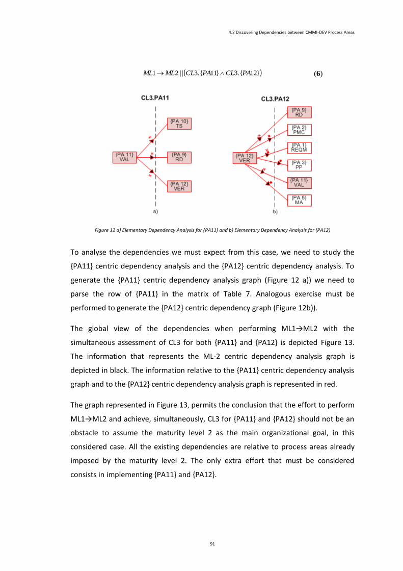
4.2 Discovering Dependencies between CMMI-DEV Process Areas
91
}12.{3}11.{3| |21 PACLPACLMLML (6)
Figure 12 a) Elementary Dependency Analysis for {PA11} and b) Elementary Dependency Analysis for {PA12}
To analyse the dependencies we must expect from this case, we need to study the
{PA11} centric dependency analysis and the {PA12} centric dependency analysis. To
generate the {PA11} centric dependency analysis graph (Figure 12 a)) we need to
parse the row of {PA11} in the matrix of Table 7. Analogous exercise must be
performed to generate the {PA12} centric dependency graph (Figure 12b)).
The global view of the dependencies when performing ML1→ML2 with the
simultaneous assessment of CL3 for both {PA11} and {PA12} is depicted Figure 13.
The information that represents the ML-2 centric dependency analysis graph is
depicted in black. The information relative to the {PA11} centric dependency analysis
graph and to the {PA12} centric dependency analysis graph is represented in red.
The graph represented in Figure 13, permits the conclusion that the effort to perform
ML1→ML2 and achieve, simultaneously, CL3 for {PA11} and {PA12} should not be an
obstacle to assume the maturity level 2 as the main organizational goal, in this
considered case. All the existing dependencies are relative to process areas already
imposed by the maturity level 2. The only extra effort that must be considered
consists in implementing {PA11} and {PA12}.
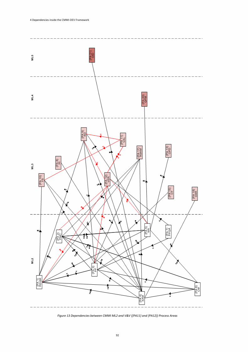
4 Dependencies inside the CMMI-DEV Framework
92
Figure 13 Dependencies between CMMI ML2 and V&V ({PA11} and {PA12}) Process Areas
4.3 Discovering Dependencies between CMMI DEV Categories
4.3 Discovering Dependencies between CMMI-DEV Categories
In this section, we complement the study of CMMI Process Areas Dependencies with
the information of CMMI chapter 4 (CMMI Product Team 2006; Chrissis et al. 2006):
Relationships among Process Areas. In that chapter 4, they describe the interactions
among process areas to allow us to see the organization’s view of process
improvement and which process areas we need to include in the implementation of
other process areas. In the following sections, we will show the new dependencies
information that arose from this CMMI chapter. The relationships among process
areas describe the information and artifacts that flow between process areas. This
flow of information and artifacts between process areas represents a dependency
between those process areas since information and artifacts used as an input on a
process area have to be produced in another process area (output of the process
area).
4.3.1 Engineering Category
The interactions between the Engineering PAs described in the CMMI documentation
in chapter 4 (Chrissis et al. 2006; CMMI Product Team 2006) are resumed in Figure
14. This bird’s-eye view shows the interaction between the Engineering PAs.
Analysing Figure 14 and the information gathered in the previous efforts we notice
that, in this new source of information, we have a set of new dependencies of which
we have not been aware. Those new dependencies are marked in red on Figure 14.
Looking at Figure 14, we can see two different types of red arrows, a filled and a
dashed arrow. The filled arrow represents new dependencies explicitly stated in the
workflow diagram. The dashed arrows represent new dependencies, which are not
explicitly stated in this bird’s-eye view. The workflow in some cases does not explicitly
state to which PA the information is sent, but indicates that a given PA sends
information to a set of PAs or to one or more Categories. The workflow shows a
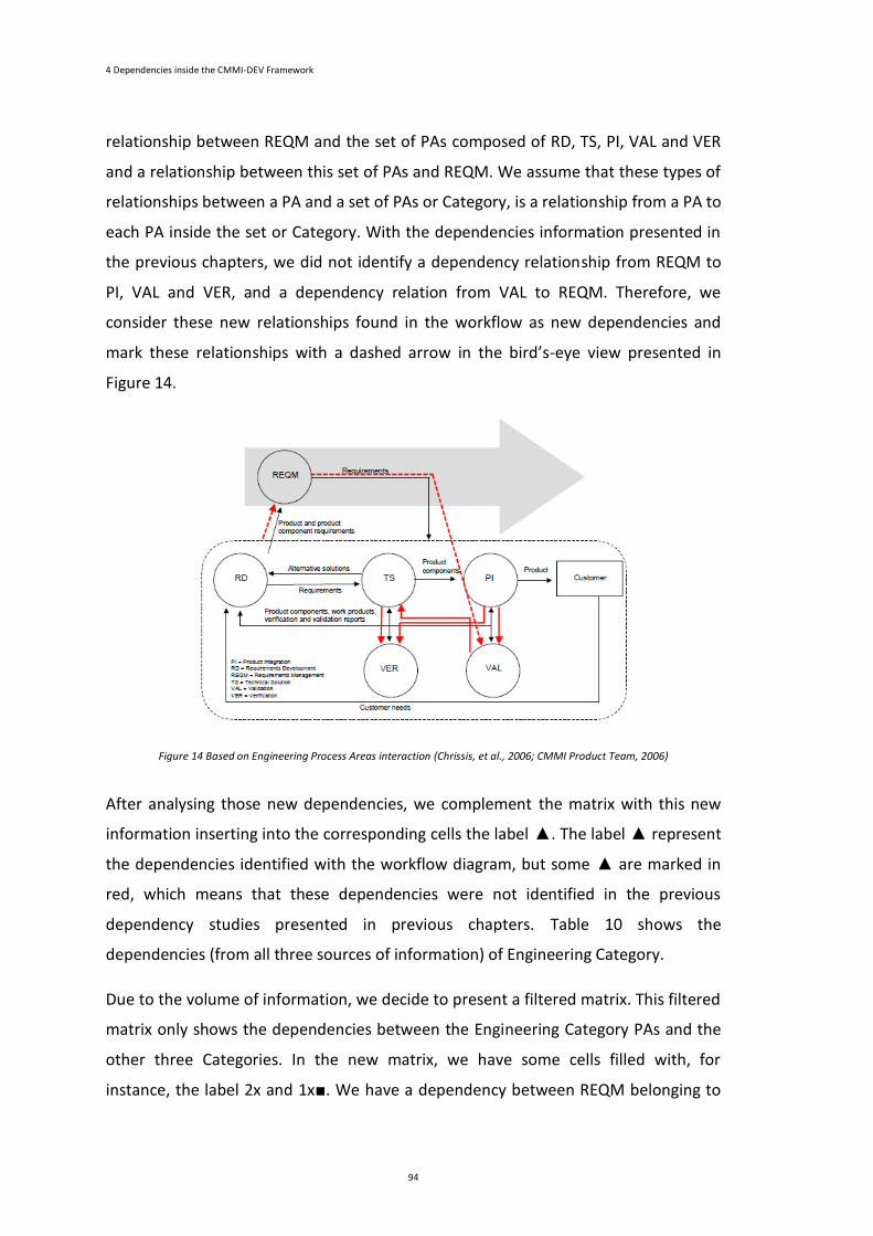
4 Dependencies inside the CMMI-DEV Framework
94
relationship between REQM and the set of PAs composed of RD, TS, PI, VAL and VER
and a relationship between this set of PAs and REQM. We assume that these types of
relationships between a PA and a set of PAs or Category, is a relationship from a PA to
each PA inside the set or Category. With the dependencies information presented in
the previous chapters, we did not identify a dependency relationship from REQM to
PI, VAL and VER, and a dependency relation from VAL to REQM. Therefore, we
consider these new relationships found in the workflow as new dependencies and
mark these relationships with a dashed arrow in the bird’s-eye view presented in
Figure 14.
Figure 14 Based on Engineering Process Areas interaction (Chrissis, et al., 2006; CMMI Product Team, 2006)
After analysing those new dependencies, we complement the matrix with this new
information inserting into the corresponding cells the label ▲. The label ▲ represent
the dependencies identified with the workflow diagram, but some ▲ are marked in
red, which means that these dependencies were not identified in the previous
dependency studies presented in previous chapters. Table 10 shows the
dependencies (from all three sources of information) of Engineering Category.
Due to the volume of information, we decide to present a filtered matrix. This filtered
matrix only shows the dependencies between the Engineering Category PAs and the
other three Categories. In the new matrix, we have some cells filled with, for
instance, the label 2x and 1x■. We have a dependency between REQM belonging to
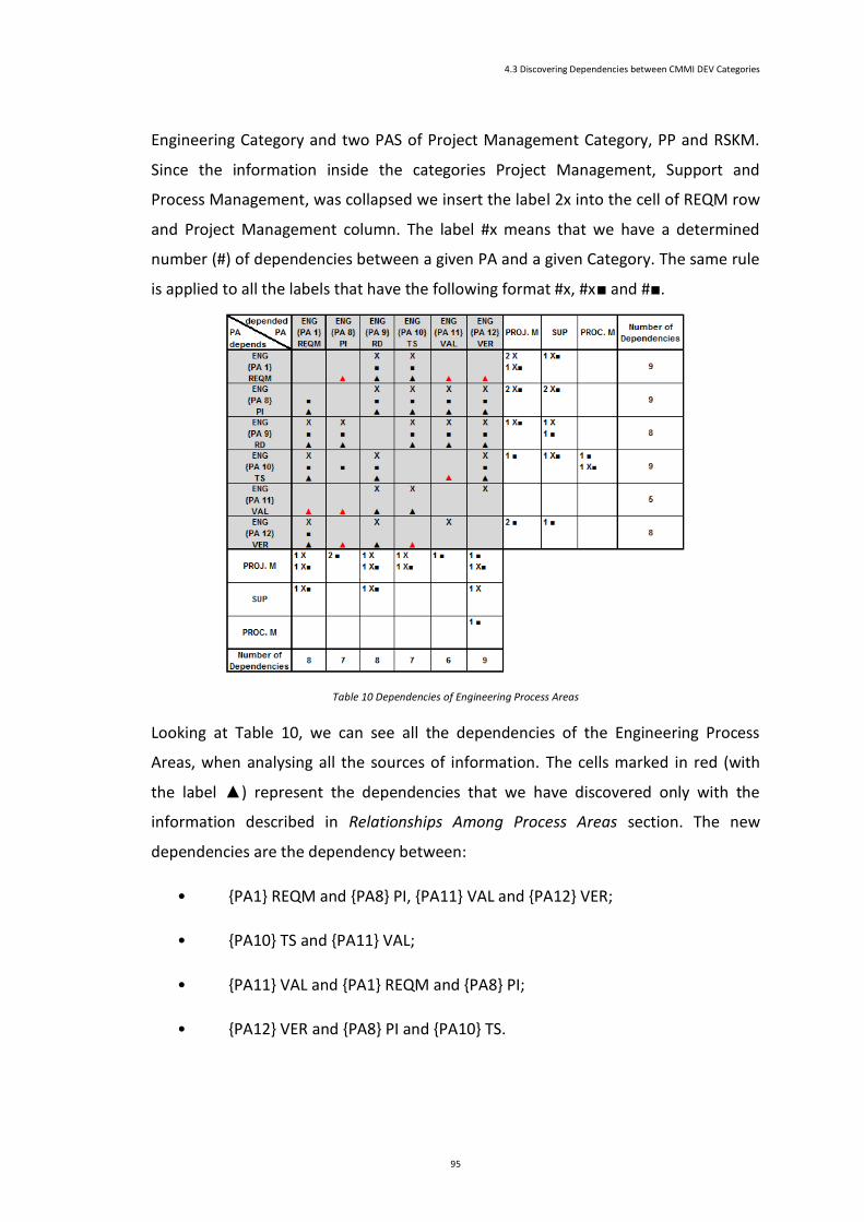
4.3 Discovering Dependencies between CMMI DEV Categories
95
Engineering Category and two PAS of Project Management Category, PP and RSKM.
Since the information inside the categories Project Management, Support and
Process Management, was collapsed we insert the label 2x into the cell of REQM row
and Project Management column. The label #x means that we have a determined
number (#) of dependencies between a given PA and a given Category. The same rule
is applied to all the labels that have the following format #x, #x■ and #■.
Table 10 Dependencies of Engineering Process Areas
Looking at Table 10, we can see all the dependencies of the Engineering Process
Areas, when analysing all the sources of information. The cells marked in red (with
the label ▲) represent the dependencies that we have discovered only with the
information described in Relationships Among Process Areas section. The new
dependencies are the dependency between:
• {PA1} REQM and {PA8} PI, {PA11} VAL and {PA12} VER;
• {PA10} TS and {PA11} VAL;
• {PA11} VAL and {PA1} REQM and {PA8} PI;
• {PA12} VER and {PA8} PI and {PA10} TS.
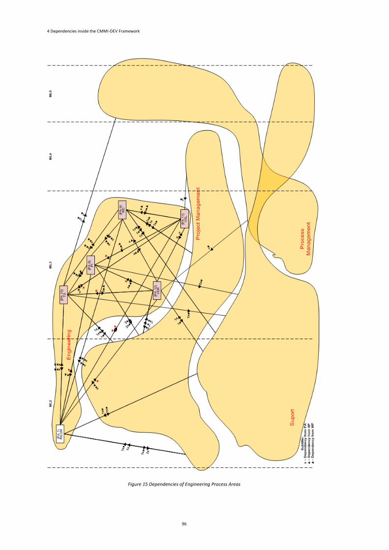
4 Dependencies inside the CMMI-DEV Framework
96
Figure 15 Dependencies of Engineering Process Areas
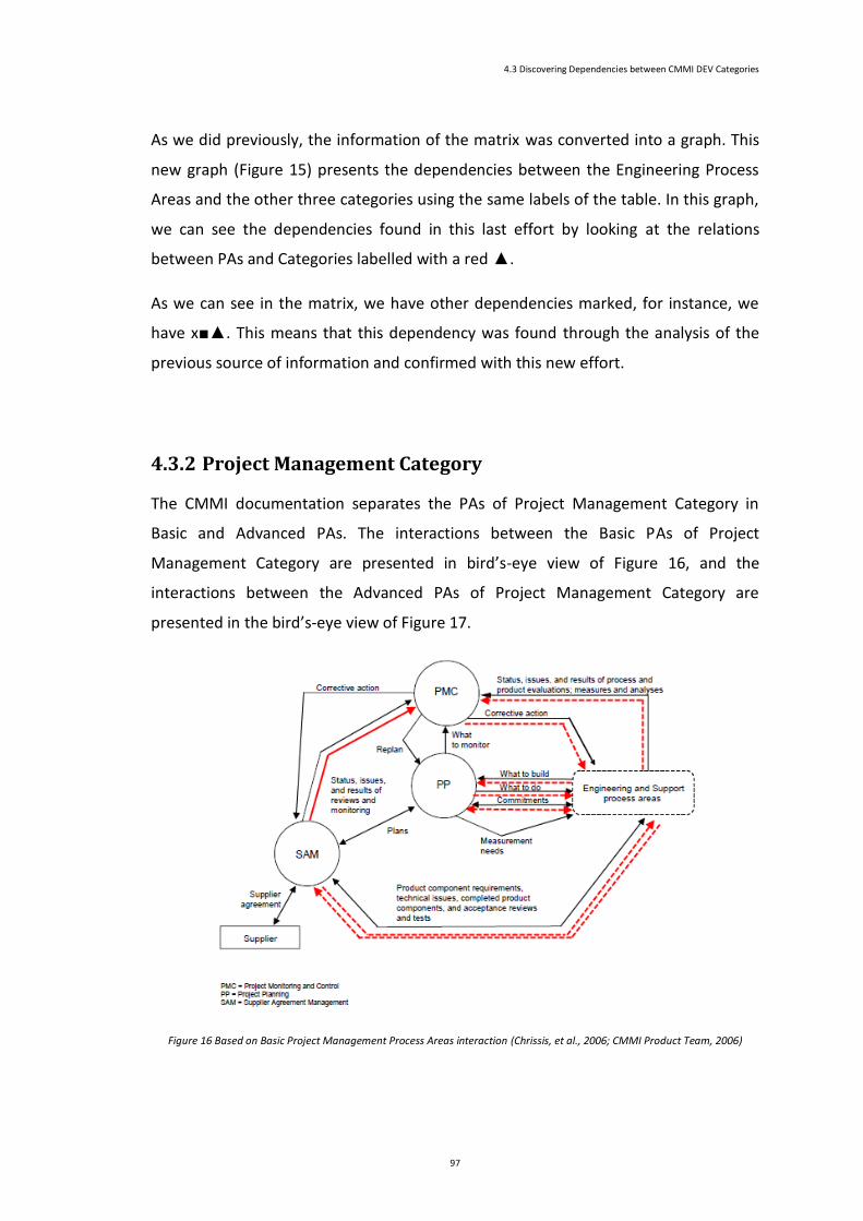
4.3 Discovering Dependencies between CMMI DEV Categories
97
As we did previously, the information of the matrix was converted into a graph. This
new graph (Figure 15) presents the dependencies between the Engineering Process
Areas and the other three categories using the same labels of the table. In this graph,
we can see the dependencies found in this last effort by looking at the relations
between PAs and Categories labelled with a red ▲.
As we can see in the matrix, we have other dependencies marked, for instance, we
have x■▲. This means that this dependency was found through the analysis of the
previous source of information and confirmed with this new effort.
4.3.2 Project Management Category
The CMMI documentation separates the PAs of Project Management Category in
Basic and Advanced PAs. The interactions between the Basic PAs of Project
Management Category are presented in bird’s-eye view of Figure 16, and the
interactions between the Advanced PAs of Project Management Category are
presented in the bird’s-eye view of Figure 17.
Figure 16 Based on Basic Project Management Process Areas interaction (Chrissis, et al., 2006; CMMI Product Team, 2006)

4 Dependencies inside the CMMI-DEV Framework
98
Analysing this new information and the dependencies information, that has been
gathered previously, we found a new set of dependencies. Like the previous category,
we mark the new dependencies in red. Once again the filled red arrows represent the
new dependencies found from a given PA to another identified PA, and the dashed
red arrows represent the new dependencies found from a given PA to a set of PAs or
Category or from a set of PAs or Category to a PA (the PAs inside the set and inside
the Category are not identified).
Figure 17 Based on Advanced Project Management Process Areas interaction (Chrissis, et al., 2006; CMMI Product Team, 2006)
The new information gathered was used to complement the matrix. In table 9, we
can see the collapsed matrix gathering all the dependencies information. Once again,
the cells marked with a red ▲ label are the new dependencies found. Analysing the
matrix we can see that the dependency of {PA4} SAM from {PA2} PMC, the
dependency of {PA2} PMC, {PA3} PP, {PA4} SAM and {PA17} RSKM from {PA16} IPM
and the dependency of {PA2} PMC, {PA3} PP, {PA4} SAM, {PA16} IPM and {PA17}
RSKM from {PA20} QPM were only discovered with this new information.
As stated before, we assume that the relations between a PA and a Category, is a
relation between a PA and each PA from a Category. Therefore, looking, for instance,
at Table 11 we saw that we identify a new dependency from {PA2} PMC to all PAs
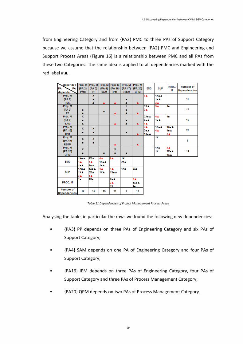
4.3 Discovering Dependencies between CMMI DEV Categories
99
from Engineering Category and from {PA2} PMC to three PAs of Support Category
because we assume that the relationship between {PA2} PMC and Engineering and
Support Process Areas (Figure 16) is a relationship between PMC and all PAs from
these two Categories. The same idea is applied to all dependencies marked with the
red label #▲.
Table 11 Dependencies of Project Management Process Areas
Analysing the table, in particular the rows we found the following new dependencies:
• {PA3} PP depends on three PAs of Engineering Category and six PAs of
Support Category;
• {PA4} SAM depends on one PA of Engineering Category and four PAs of
Support Category;
• {PA16} IPM depends on three PAs of Engineering Category, four PAs of
Support Category and three PAs of Process Management Category;
• {PA20} QPM depends on two PAs of Process Management Category.
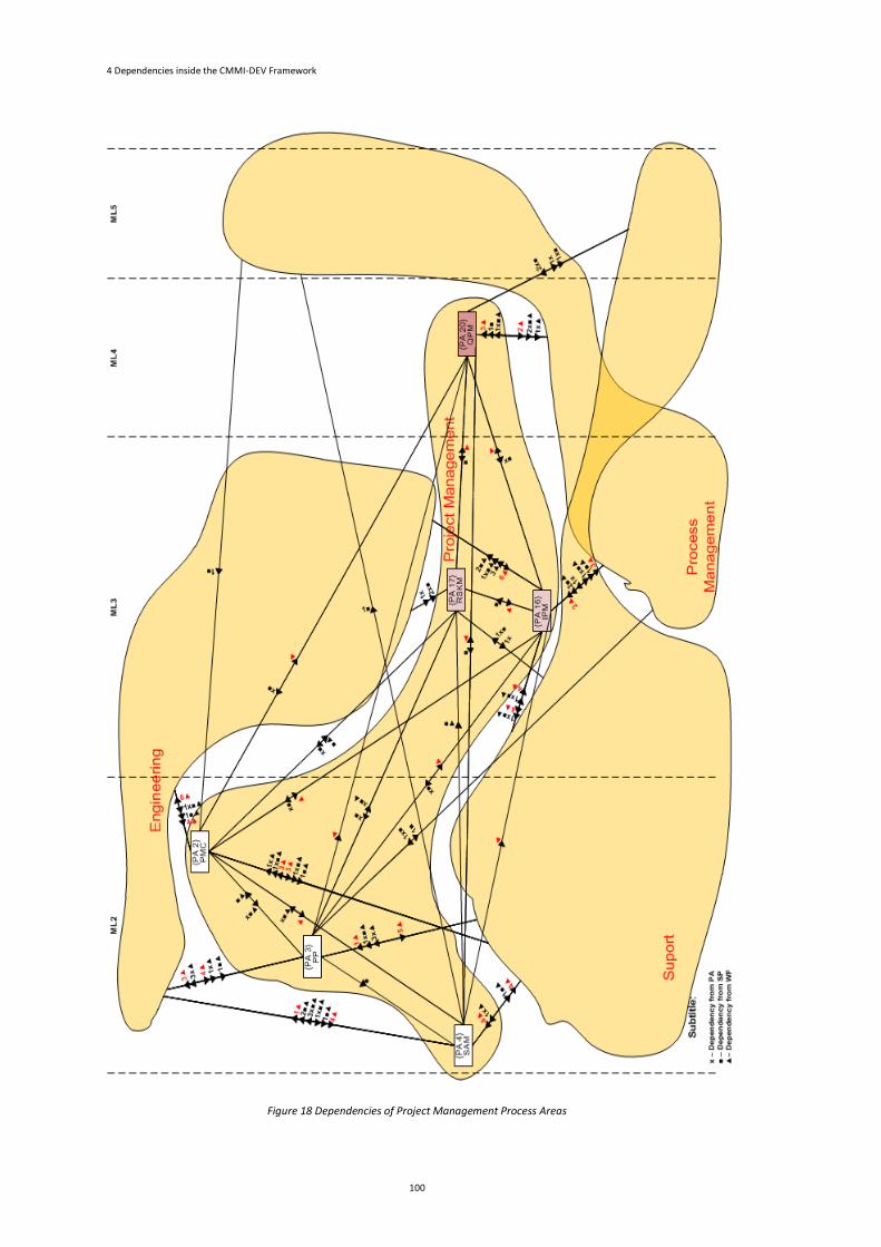
4 Dependencies inside the CMMI-DEV Framework
100
Figure 18 Dependencies of Project Management Process Areas
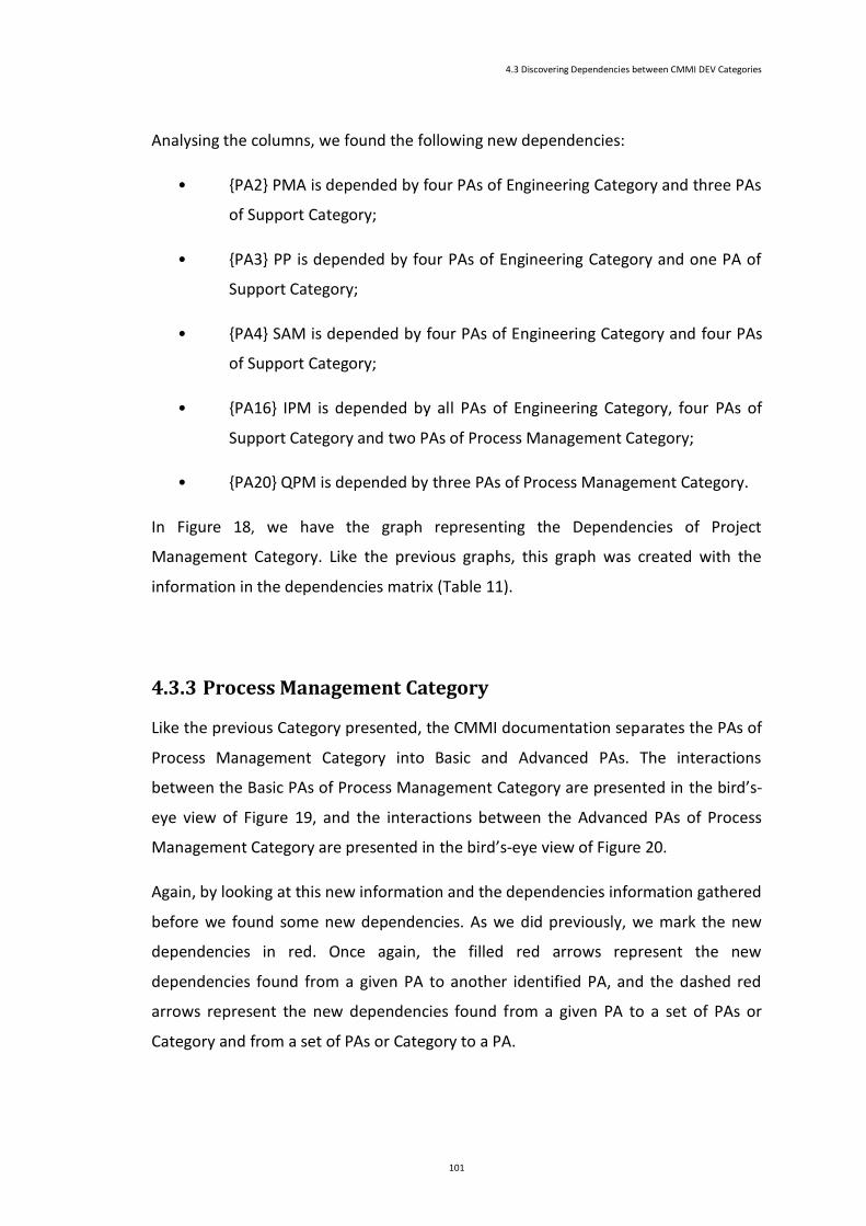
4.3 Discovering Dependencies between CMMI DEV Categories
101
Analysing the columns, we found the following new dependencies:
• {PA2} PMA is depended by four PAs of Engineering Category and three PAs
of Support Category;
• {PA3} PP is depended by four PAs of Engineering Category and one PA of
Support Category;
• {PA4} SAM is depended by four PAs of Engineering Category and four PAs
of Support Category;
• {PA16} IPM is depended by all PAs of Engineering Category, four PAs of
Support Category and two PAs of Process Management Category;
• {PA20} QPM is depended by three PAs of Process Management Category.
In Figure 18, we have the graph representing the Dependencies of Project
Management Category. Like the previous graphs, this graph was created with the
information in the dependencies matrix (Table 11).
4.3.3 Process Management Category
Like the previous Category presented, the CMMI documentation separates the PAs of
Process Management Category into Basic and Advanced PAs. The interactions
between the Basic PAs of Process Management Category are presented in the bird’s-
eye view of Figure 19, and the interactions between the Advanced PAs of Process
Management Category are presented in the bird’s-eye view of Figure 20.
Again, by looking at this new information and the dependencies information gathered
before we found some new dependencies. As we did previously, we mark the new
dependencies in red. Once again, the filled red arrows represent the new
dependencies found from a given PA to another identified PA, and the dashed red
arrows represent the new dependencies found from a given PA to a set of PAs or
Category and from a set of PAs or Category to a PA.
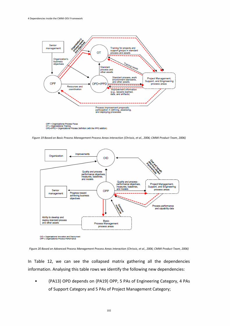
4 Dependencies inside the CMMI-DEV Framework
102
Figure 19 Based on Basic Process Management Process Areas interaction (Chrissis, et al., 2006; CMMI Product Team, 2006)
Figure 20 Based on Advanced Process Management Process Areas interaction (Chrissis, et al., 2006; CMMI Product Team, 2006)
In Table 12, we can see the collapsed matrix gathering all the dependencies
information. Analysing this table rows we identify the following new dependencies:
• {PA13} OPD depends on {PA19} OPP, 5 PAs of Engineering Category, 4 PAs
of Support Category and 5 PAs of Project Management Category;
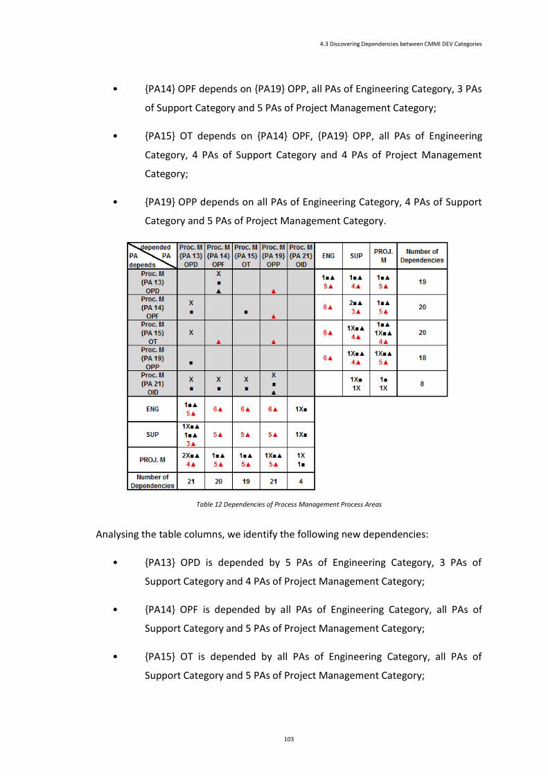
4.3 Discovering Dependencies between CMMI DEV Categories
103
• {PA14} OPF depends on {PA19} OPP, all PAs of Engineering Category, 3 PAs
of Support Category and 5 PAs of Project Management Category;
• {PA15} OT depends on {PA14} OPF, {PA19} OPP, all PAs of Engineering
Category, 4 PAs of Support Category and 4 PAs of Project Management
Category;
• {PA19} OPP depends on all PAs of Engineering Category, 4 PAs of Support
Category and 5 PAs of Project Management Category.
Table 12 Dependencies of Process Management Process Areas
Analysing the table columns, we identify the following new dependencies:
• {PA13} OPD is depended by 5 PAs of Engineering Category, 3 PAs of
Support Category and 4 PAs of Project Management Category;
• {PA14} OPF is depended by all PAs of Engineering Category, all PAs of
Support Category and 5 PAs of Project Management Category;
• {PA15} OT is depended by all PAs of Engineering Category, all PAs of
Support Category and 5 PAs of Project Management Category;
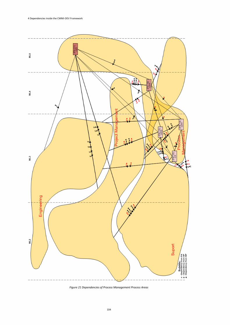
4 Dependencies inside the CMMI-DEV Framework
104
Figure 21 Dependencies of Process Management Process Areas
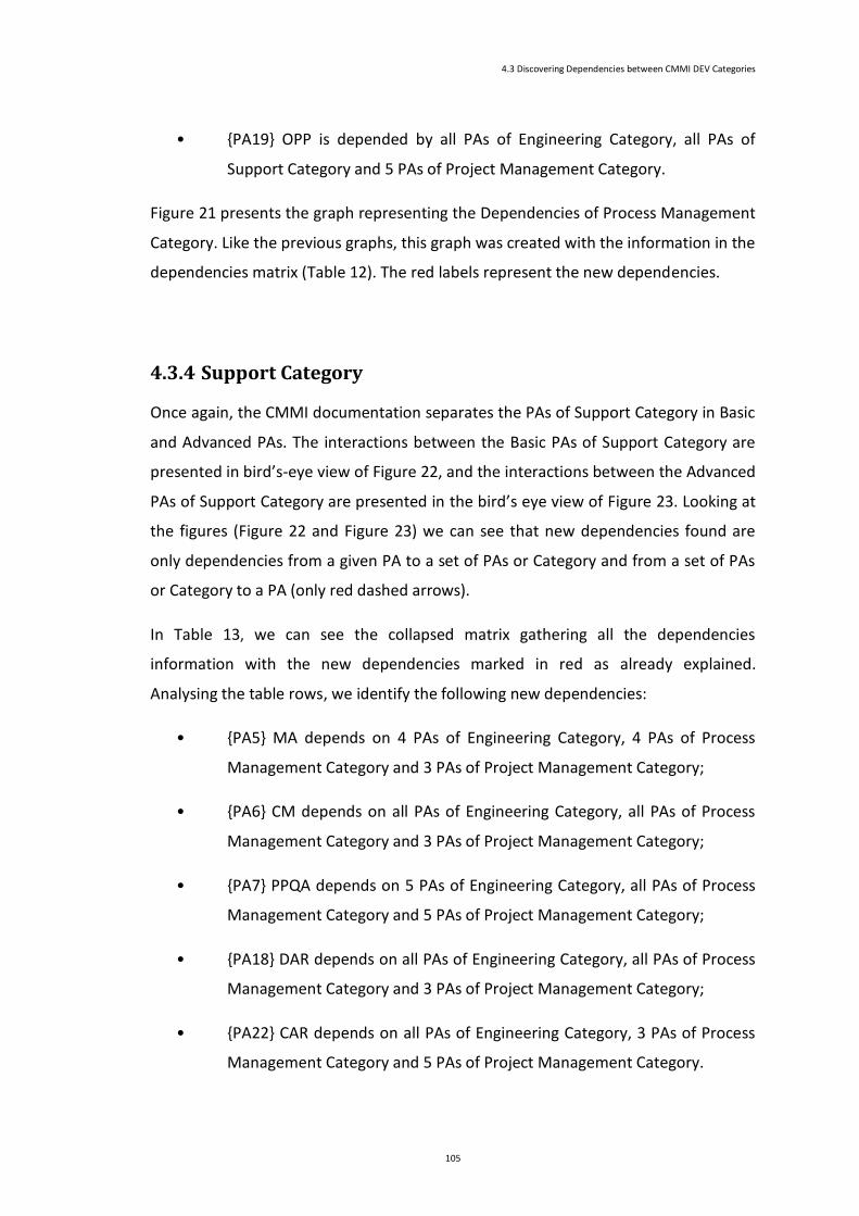
4.3 Discovering Dependencies between CMMI DEV Categories
105
• {PA19} OPP is depended by all PAs of Engineering Category, all PAs of
Support Category and 5 PAs of Project Management Category.
Figure 21 presents the graph representing the Dependencies of Process Management
Category. Like the previous graphs, this graph was created with the information in the
dependencies matrix (Table 12). The red labels represent the new dependencies.
4.3.4 Support Category
Once again, the CMMI documentation separates the PAs of Support Category in Basic
and Advanced PAs. The interactions between the Basic PAs of Support Category are
presented in bird’s-eye view of Figure 22, and the interactions between the Advanced
PAs of Support Category are presented in the bird’s eye view of Figure 23. Looking at
the figures (Figure 22 and Figure 23) we can see that new dependencies found are
only dependencies from a given PA to a set of PAs or Category and from a set of PAs
or Category to a PA (only red dashed arrows).
In Table 13, we can see the collapsed matrix gathering all the dependencies
information with the new dependencies marked in red as already explained.
Analysing the table rows, we identify the following new dependencies:
• {PA5} MA depends on 4 PAs of Engineering Category, 4 PAs of Process
Management Category and 3 PAs of Project Management Category;
• {PA6} CM depends on all PAs of Engineering Category, all PAs of Process
Management Category and 3 PAs of Project Management Category;
• {PA7} PPQA depends on 5 PAs of Engineering Category, all PAs of Process
Management Category and 5 PAs of Project Management Category;
• {PA18} DAR depends on all PAs of Engineering Category, all PAs of Process
Management Category and 3 PAs of Project Management Category;
• {PA22} CAR depends on all PAs of Engineering Category, 3 PAs of Process
Management Category and 5 PAs of Project Management Category.
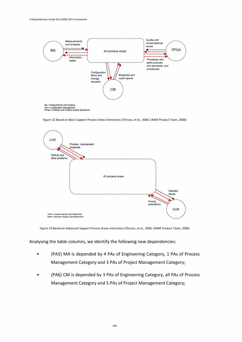
4 Dependencies inside the CMMI-DEV Framework
106
Figure 22 Based on Basic Support Process Areas interaction (Chrissis, et al., 2006; CMMI Product Team, 2006)
Figure 23 Based on Advanced Support Process Areas interaction (Chrissis, et al., 2006; CMMI Product Team, 2006)
Analysing the table columns, we identify the following new dependencies:
• {PA5} MA is depended by 4 PAs of Engineering Category, 1 PAs of Process
Management Category and 3 PAs of Project Management Category;
• {PA6} CM is depended by 3 PAs of Engineering Category, all PAs of Process
Management Category and 5 PAs of Project Management Category;
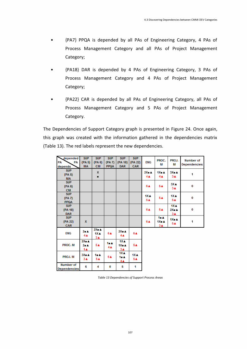
4.3 Discovering Dependencies between CMMI DEV Categories
107
• {PA7} PPQA is depended by all PAs of Engineering Category, 4 PAs of
Process Management Category and all PAs of Project Management
Category;
• {PA18} DAR is depended by 4 PAs of Engineering Category, 3 PAs of
Process Management Category and 4 PAs of Project Management
Category;
• {PA22} CAR is depended by all PAs of Engineering Category, all PAs of
Process Management Category and 5 PAs of Project Management
Category.
The Dependencies of Support Category graph is presented in Figure 24. Once again,
this graph was created with the information gathered in the dependencies matrix
(Table 13). The red labels represent the new dependencies.
Table 13 Dependencies of Support Process Areas
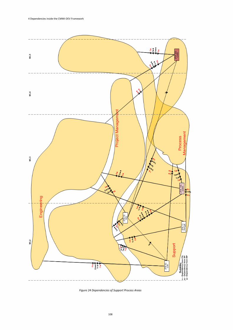
4 Dependencies inside the CMMI-DEV Framework
108
Figure 24 Dependencies of Support Process Areas
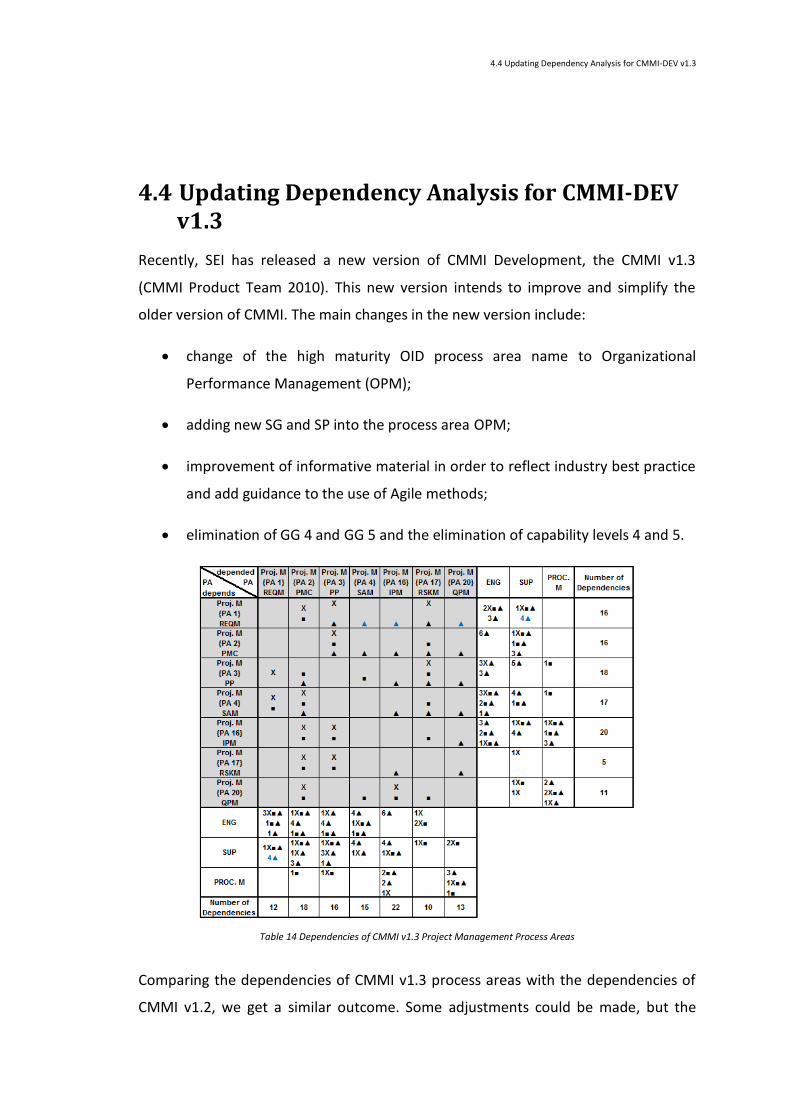
4.4 Updating Dependency Analysis for CMMI-DEV v1.3
4.4 Updating Dependency Analysis for CMMI-DEV v1.3
Recently, SEI has released a new version of CMMI Development, the CMMI v1.3
(CMMI Product Team 2010). This new version intends to improve and simplify the
older version of CMMI. The main changes in the new version include:
change of the high maturity OID process area name to Organizational
Performance Management (OPM);
adding new SG and SP into the process area OPM;
improvement of informative material in order to reflect industry best practice
and add guidance to the use of Agile methods;
elimination of GG 4 and GG 5 and the elimination of capability levels 4 and 5.
Table 14 Dependencies of CMMI v1.3 Project Management Process Areas
Comparing the dependencies of CMMI v1.3 process areas with the dependencies of
CMMI v1.2, we get a similar outcome. Some adjustments could be made, but the
4 Dependencies inside the CMMI-DEV Framework
110
differences between the two models are not significant enough to impose this change
right now.
The differences between the CMMI V1.2 dependencies and the CMMI v1.3 are small.
As an example, we present the CMMI v1.3 dependencies of Project Management PAs.
One of the differences identified is the introduction in Project Management Category
of {PA1} REQM. In CMMI v1.2, {PA1} REQM was an Engineering PA. As a consequence
of this change a new group of dependencies were identified. The new dependencies
are all between the {PA1} REQM PA and the other Project Management PAs and
Support PAs. Table 14 shows these new dependencies.
4.5 Conclusion
CMMI official documentation does not explicitly describe the existing dependencies
among the process areas. To find out the global theoretical dependencies, we need to
complement the reading of the documentation with special care and analysis
capabilities, but, even after that, it is hard to obtain the global view of the
dependencies. The final goal is not to reach the global theoretical dependencies, but
rather to use this view as a characterization of the framework limitations to be next
confronted with the dependencies we can observe in the implementation of real SPI
projects (by adopting SCAMPI appraisals whether for ML or CL assessments). This
means that this chapter will be considered as a baseline for future comparisons with
empirical results.
In this chapter, we describe a set of techniques to identify the dependencies between
all the process areas and create a global view of those dependencies by means of
some matrix and a set of graphs. We have also developed a notation that translates
the meaning of achieving a particular capability and maturity level. This notation
allows understanding which specific practices and specific goals have to be
implemented to achieve a given capability and maturity level.
The main motivation to detail the global dependencies between CMMI process areas
arose when we tried to understand the impact of implementing the maturity level 2
4.5 Conclusion
111
simultaneously with some process areas from maturity level 3 as a way to make
CMMI more widely used in Portuguese SMEs. As an example, we analysed the
dependencies between the process areas of maturity level 2 and two particular
process areas of maturity level 3.
This work complements the previous dependency analysis with the interactions
between the process areas of each category in order to analyse if those interactions
are already identified as a dependency between the process areas. For this study, we
used the information described with the bird’s-eye view presented in (CMMI Product
Team 2006). Another source of information that used to complement this
dependency study was the SG descriptions of each PA.
This complementary study leads us to the identification of a new set of dependencies
that, again, are not well described in the CMMI official documentation.

Chapter 5
Mapping CMMI and RUP Process Frameworks
Chapter Contents
5 Mapping CMMI and RUP Process Frameworks ...............................................................................115
5.1 Introduction .............................................................................................................................115
5.2 General CMMI-RUP Mapping for ML2 and ML3 .......................................................................116
5.3 Detailing Mappings for Supporting Project Proposals (PP and REQM Alignment) .....................126
5.4 Detailing Mappings for Supporting ML2 Projects Execution .....................................................130
5.5 Evolution of CMMI-RUP Tasks Accomplishment .......................................................................142
5.6 Conclusion ...............................................................................................................................148

114
115
5
Mapping CMMI and RUP
Process Frameworks
This chapter presents a conceptual mapping of CMMI and RUP frameworks to assist in
the CMMI compliance achievement. For each CMMI ML2 and ML3 process area, a set
of RUP tasks or activities is presented that will help the achievement of those maturity
levels. This chapter also presents a detailed mapping of CMMI ML2 and RUP
framework. This detailed mapping covers two different contexts: the project proposal
elaboration and the software development projects execution. It ends with the
evaluation of the RUP tasks and activities accomplishment distribution over the
Inception, Elaboration and Construction phases.
5.1 Introduction
To improve quality, organizations are widely using Software Process Improvement
(SPI) models and, in particular, CMMI. Nevertheless, Small and Medium Enterprises
(SMEs) are reluctant to adopt CMMI since the complexity and size of the framework
discourages its acceptance. RUP is presented as a disciplined approach for assigning
tasks and responsibilities within a software organization, with the aim of ensuring the
production of software meeting the users’ needs and in strict compliance with a
predictable timetable and budget. CMMI and RUP can be used together since CMMI

5 Mapping CMMI and RUP Process Frameworks
116
defines “what to do” and RUP defines “how to do”. In this chapter, we present the
mappings between the CMMI Maturity Levels 2 and 3 process areas and the RUP
activities, tasks, artifacts and roles. The main contribution relates to the alignment of
CMMI and RUP when adopted in the preliminary stage of every project, the
elaboration of the project proposal and in the software development execution.
One of the main purposes of this work is to discuss if RUP for small projects (IBM,
2006b) is enough to elaborate project proposals in a CMMI ML2 organization. Usually,
one project proposal is a response to a client request. However, it could also be
required for internal purposes of the company (Kurbel, 2008; Nebiu, 2002; Procter et
al., 2011; Tatum, 2012). The project proposal document should be composed of the
plan of action, the reasons for each action, the timeline to perform the project, the
methodology that will be used and the budget required to perform (execute) the
project. The ultimate goal of each project proposal is to describe and explain a
detailed description of the actions and activities needed to solve a given problem (the
problem that motivates the client to ask for a particular project).
The other main purpose of this work is to discuss whether, through the adoption of
RUP in software development projects execution, it is possible to achieve CMMI ML2.
We will start by presenting the mapping of CMMI ML2 and ML3 process areas into
RUP tasks, activities and roles. Since we are concerned with the elaboration of project
proposals and the execution of software development projects, we will focus mainly
on the RUP Inception, Elaboration and Construction phase and the CMMI REQM and
PP process areas for the first goal and the CMMI ML2 Process Areas for the second
goal.
5.2 General CMMI-RUP Mapping for ML2 and ML3
As a first step to the main goals, we have performed an extension to the mapping
described in (Grundmann, 2005; IBM, 2007; Uttangi & Rizwan) that relates “CMMI-
DEV v1.2 ML2” and “RUP for large projects”. We have extended the IBM work by
reviewing the CMMI-RUP mapping for ML2 to the new RUP version and by proposing
a CMMI-RUP mapping for ML3. We had to map CMMI ML3 specific practices and
5.2 General CMMI-RUP Mapping for ML2 and ML3
117
subpractices into RUP activities or tasks and CMMI ML3 work products into RUP
artifacts.
It is necessary to clarify that one PA is composed of one or more specific goals (SGs);
one SG is divided into one or more specific practices (SP), and one SP is divided into
one or more subpractices. To implement one PA, we have to fully cover all the
process area SPs, which means that we have to fully cover all the subpractices that
compose the SPs.
When performing the initial CMMI-RUP gap analysis, we had to consider different
coverage levels:
• High coverage (H): CMMI fully implemented with RUP elements, which
means that there are no substantial weaknesses;
• Medium-High coverage (MH): CMMI nearly fully implemented with RUP
elements, although some weaknesses can be identified;
• Medium coverage (M): CMMI mostly implemented with RUP elements,
however, additional effort is needed to fully implement this process area
using RUP;
• Low coverage (L): CMMI is not directly supported using RUP elements, or
there is a minimal RUP support;
• Not covered (N): CMMI is not covered with any RUP elements.
Table 15 presents the results of CMMI-RUP gap analysis for ML2 and ML3. Two tasks
are needed to perform this gap analysis: (1) identify all the RUP activities, tasks and
artifacts needed to perform each one of the SPs, subpractices and work products for
each process area; (2) identify the RUP roles assigned to each RUP activities, tasks
and artifacts of each process area. All process areas of CMMI ML2 are totally or, at
least, partially covered by RUP. In the case of ML3, process areas belonging to the
process management and support categories are not covered by RUP.
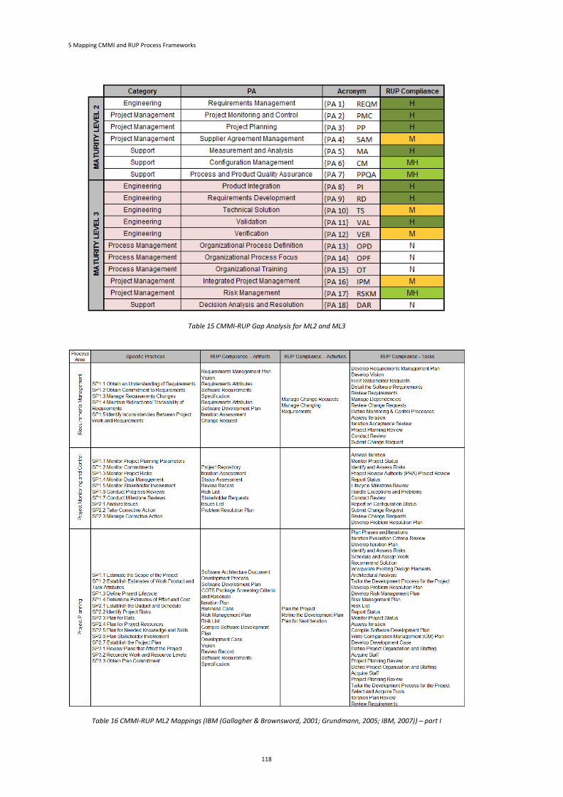
5 Mapping CMMI and RUP Process Frameworks
118
Table 15 CMMI-RUP Gap Analysis for ML2 and ML3
Table 16 CMMI-RUP ML2 Mappings (IBM (Gallagher & Brownsword, 2001; Grundmann, 2005; IBM, 2007)) – part I
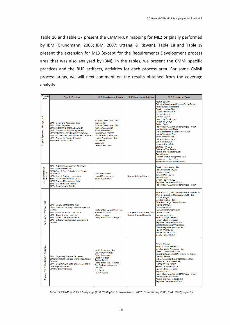
5.2 General CMMI-RUP Mapping for ML2 and ML3
119
Table 16 and Table 17 present the CMMI-RUP mapping for ML2 originally performed
by IBM (Grundmann, 2005; IBM, 2007; Uttangi & Rizwan). Table 18 and Table 19
present the extension for ML3 (except for the Requirements Development process
area that was also analysed by IBM). In the tables, we present the CMMI specific
practices and the RUP artifacts, activities for each process area. For some CMMI
process areas, we will next comment on the results obtained from the coverage
analysis.
Table 17 CMMI-RUP ML2 Mappings (IBM (Gallagher & Brownsword, 2001; Grundmann, 2005; IBM, 2007)) – part II
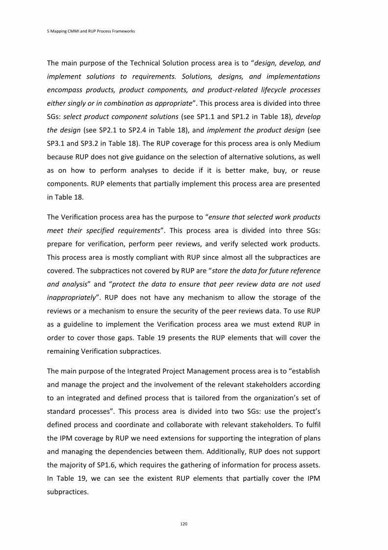
5 Mapping CMMI and RUP Process Frameworks
120
The main purpose of the Technical Solution process area is to “design, develop, and
implement solutions to requirements. Solutions, designs, and implementations
encompass products, product components, and product-related lifecycle processes
either singly or in combination as appropriate”. This process area is divided into three
SGs: select product component solutions (see SP1.1 and SP1.2 in Table 18), develop
the design (see SP2.1 to SP2.4 in Table 18), and implement the product design (see
SP3.1 and SP3.2 in Table 18). The RUP coverage for this process area is only Medium
because RUP does not give guidance on the selection of alternative solutions, as well
as on how to perform analyses to decide if it is better make, buy, or reuse
components. RUP elements that partially implement this process area are presented
in Table 18.
The Verification process area has the purpose to “ensure that selected work products
meet their specified requirements”. This process area is divided into three SGs:
prepare for verification, perform peer reviews, and verify selected work products.
This process area is mostly compliant with RUP since almost all the subpractices are
covered. The subpractices not covered by RUP are “store the data for future reference
and analysis” and “protect the data to ensure that peer review data are not used
inappropriately”. RUP does not have any mechanism to allow the storage of the
reviews or a mechanism to ensure the security of the peer reviews data. To use RUP
as a guideline to implement the Verification process area we must extend RUP in
order to cover those gaps. Table 19 presents the RUP elements that will cover the
remaining Verification subpractices.
The main purpose of the Integrated Project Management process area is to “establish
and manage the project and the involvement of the relevant stakeholders according
to an integrated and defined process that is tailored from the organization’s set of
standard processes”. This process area is divided into two SGs: use the project’s
defined process and coordinate and collaborate with relevant stakeholders. To fulfil
the IPM coverage by RUP we need extensions for supporting the integration of plans
and managing the dependencies between them. Additionally, RUP does not support
the majority of SP1.6, which requires the gathering of information for process assets.
In Table 19, we can see the existent RUP elements that partially cover the IPM
subpractices.
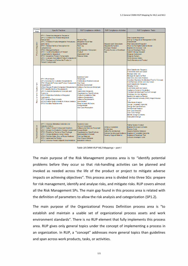
5.2 General CMMI-RUP Mapping for ML2 and ML3
121
Table 18 CMMI-RUP ML3 Mappings – part I
The main purpose of the Risk Management process area is to “identify potential
problems before they occur so that risk-handling activities can be planned and
invoked as needed across the life of the product or project to mitigate adverse
impacts on achieving objectives“. This process area is divided into three SGs: prepare
for risk management, identify and analyse risks, and mitigate risks. RUP covers almost
all the Risk Management SPs. The main gap found in this process area is related with
the definition of parameters to allow the risk analysis and categorization (SP1.2).
The main purpose of the Organizational Process Definition process area is “to
establish and maintain a usable set of organizational process assets and work
environment standards“. There is no RUP element that fully implements this process
area. RUP gives only general topics under the concept of implementing a process in
an organization. In RUP, a “concept” addresses more general topics than guidelines
and span across work products, tasks, or activities.
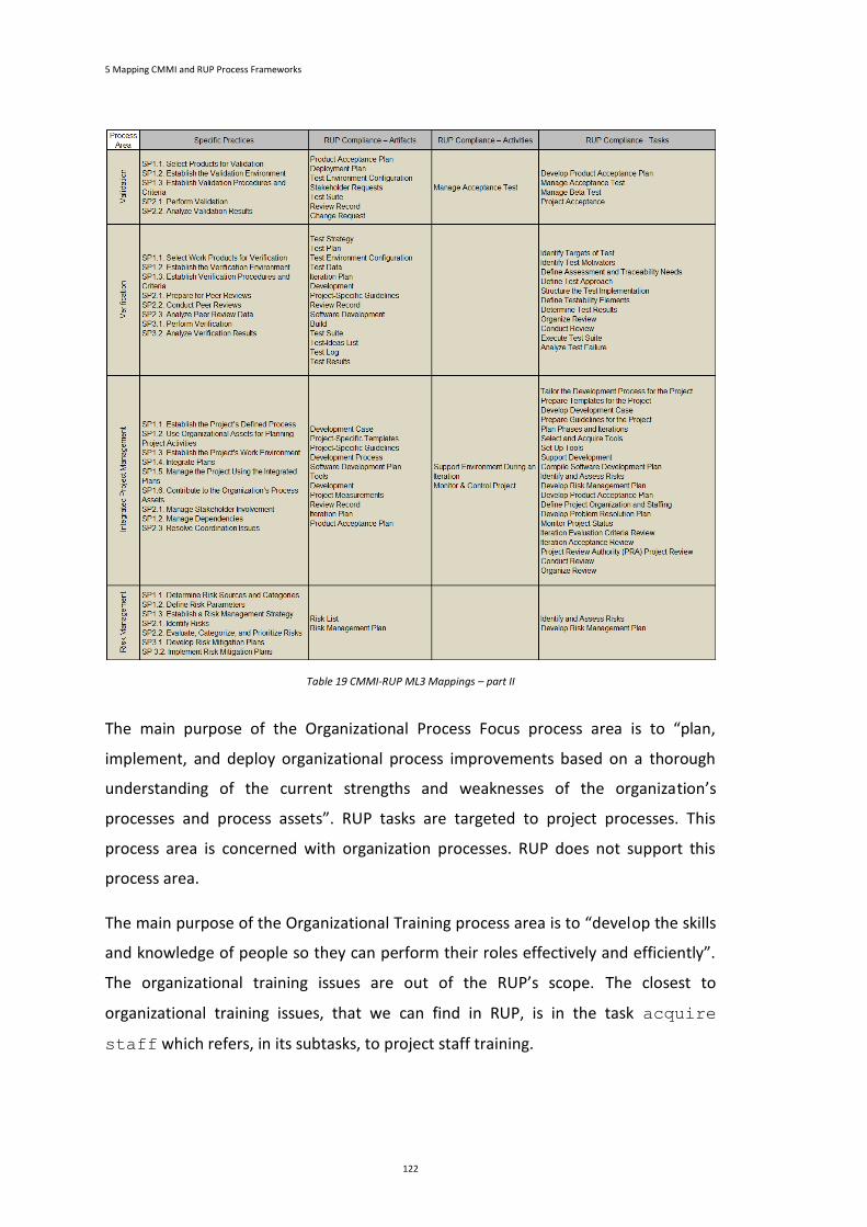
5 Mapping CMMI and RUP Process Frameworks
122
Table 19 CMMI-RUP ML3 Mappings – part II
The main purpose of the Organizational Process Focus process area is to “plan,
implement, and deploy organizational process improvements based on a thorough
understanding of the current strengths and weaknesses of the organization’s
processes and process assets”. RUP tasks are targeted to project processes. This
process area is concerned with organization processes. RUP does not support this
process area.
The main purpose of the Organizational Training process area is to “develop the skills
and knowledge of people so they can perform their roles effectively and efficiently”.
The organizational training issues are out of the RUP’s scope. The closest to
organizational training issues, that we can find in RUP, is in the task acquire
staff which refers, in its subtasks, to project staff training.
5.2 General CMMI-RUP Mapping for ML2 and ML3
123
The main purpose of the Decision Analysis and Resolution process area is “to analyse
possible decisions using a formal evaluation process that evaluates identified
alternatives against established criteria”. RUP scope does not cover the main issues of
this process area.
5.2.1 Reduced Model Roles for ML2 and ML3 Process Areas
The described CMMI-RUP mappings are useful to understand what to expect in terms
of CMMI coverage when adopting RUP as a development process framework. In
terms of execution, it is important to perceive additionally who should be responsible
for compliance with each CMMI general goal, and perform each CMMI specific
practice. Here, we have considered the RUP Reduced Model presented in (Paula
Monteiro et al., 2012) as a first step towards the attribution of responsibilities in
terms of CMMI implementation supported by RUP.
Table 20 Roles Considered in RUP Reduced Model
Table 20 summarizes the eight RUP Reduced Model roles (project manager,
integrator, project reviewer, process engineer, implementer,
system administrator, test manager and system tester). The
remaining 29 roles are not discarded; their responsibilities are mapped into one of
the eight Reduced Model roles. For instance, the project manager inherits the
responsibilities of business-process analyst, change control
manager, deployment manager, requirements specifier, review
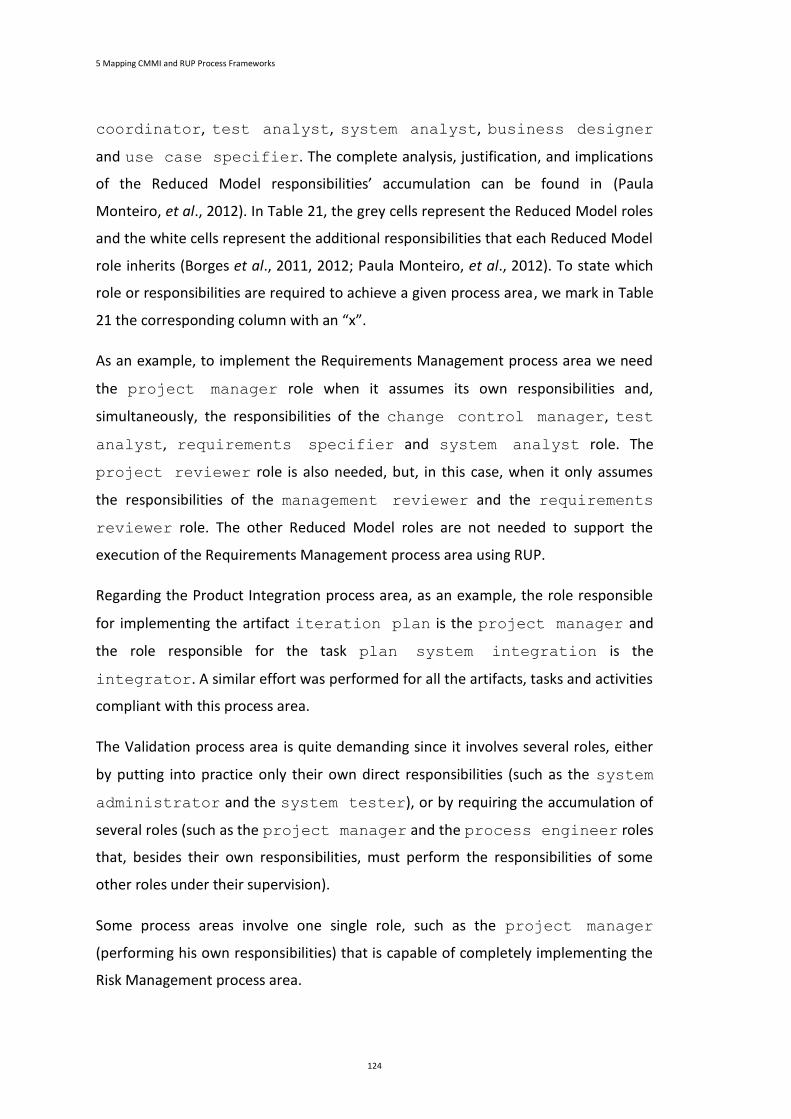
5 Mapping CMMI and RUP Process Frameworks
124
coordinator, test analyst, system analyst, business designer
and use case specifier. The complete analysis, justification, and implications
of the Reduced Model responsibilities’ accumulation can be found in (Paula
Monteiro, et al., 2012). In Table 21, the grey cells represent the Reduced Model roles
and the white cells represent the additional responsibilities that each Reduced Model
role inherits (Borges et al., 2011, 2012; Paula Monteiro, et al., 2012). To state which
role or responsibilities are required to achieve a given process area, we mark in Table
21 the corresponding column with an “x”.
As an example, to implement the Requirements Management process area we need
the project manager role when it assumes its own responsibilities and,
simultaneously, the responsibilities of the change control manager, test
analyst, requirements specifier and system analyst role. The
project reviewer role is also needed, but, in this case, when it only assumes
the responsibilities of the management reviewer and the requirements
reviewer role. The other Reduced Model roles are not needed to support the
execution of the Requirements Management process area using RUP.
Regarding the Product Integration process area, as an example, the role responsible
for implementing the artifact iteration plan is the project manager and
the role responsible for the task plan system integration is the
integrator. A similar effort was performed for all the artifacts, tasks and activities
compliant with this process area.
The Validation process area is quite demanding since it involves several roles, either
by putting into practice only their own direct responsibilities (such as the system
administrator and the system tester), or by requiring the accumulation of
several roles (such as the project manager and the process engineer roles
that, besides their own responsibilities, must perform the responsibilities of some
other roles under their supervision).
Some process areas involve one single role, such as the project manager
(performing his own responsibilities) that is capable of completely implementing the
Risk Management process area.
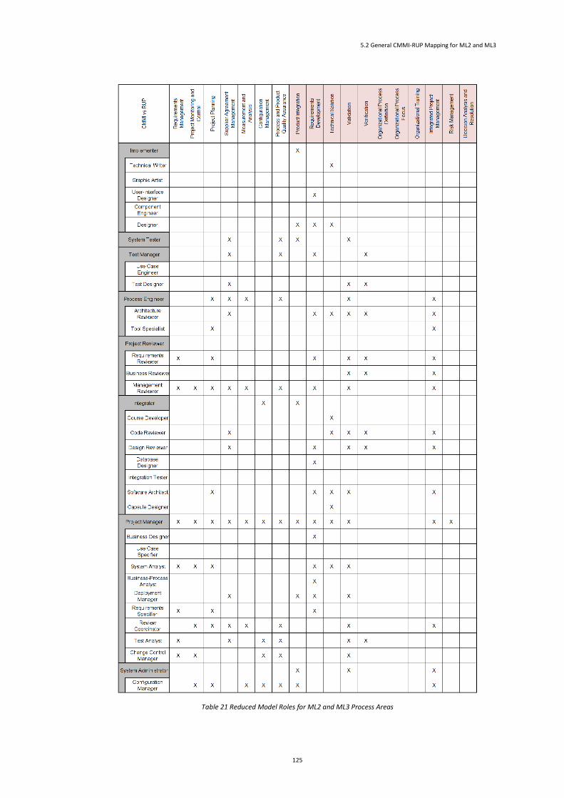
5.2 General CMMI-RUP Mapping for ML2 and ML3
125
Table 21 Reduced Model Roles for ML2 and ML3 Process Areas
5 Mapping CMMI and RUP Process Frameworks
126
5.3 Detailing Mappings for Supporting Project Proposals (PP and REQM Alignment)
Since our first main goal is to understand what level of support we can expect from
RUP, to elaborate project proposals in a CMMI-compliant perspective, it is extremely
important to detail the previous analysis for both the Project Planning and
Requirements Management process areas at the subpractices level.
Table 22 presents the detailed CMMI-RUP for the Project Planning process area. The
table contains the required RUP tasks or activities to support each Project Planning
subpractice. Artifacts were replaced by tasks of which they are output.
Project Planning process area has good support from RUP (H coverage); with a few
recommendations and actions we can completely cover this process area using RUP
tasks and activities.
We can highlight the subpractice SP1.4.1 (that can be nearly implemented with the
RUP task plan phases and iterations) and the subpractice SP1.4.2 (that
can be practically implemented with the RUP task schedule and assign
work). However, these two subpractices do not cover the estimation process.
Therefore, to achieve a high coverage, an estimation process should be added to RUP.
Subpractices SP2.3.1 could also be better supported if we upgrade the RUP task
write configuration management (CM) plan with the capability of
including privacy and security requirements the RUP artifact configuration
management plan.
Subpractices SP2.4.3 could be better supported if we upgrade the RUP task select
and acquire tools with the capability of identifying the facilities, equipment,
and component requirements for all project activities.
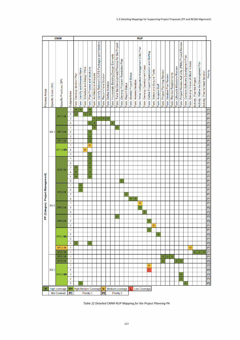
5.3 Detailing Mappings for Supporting Project Proposals (PP and REQM Alignment)
127
Table 22 Detailed CMMI-RUP Mapping for the Project Planning PA
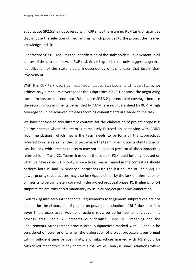
5 Mapping CMMI and RUP Process Frameworks
128
Subpractice SP2.5.3 is not covered with RUP since there are no RUP tasks or activities
that impose the selection of mechanisms, which provides to the project the needed
knowledge and skills.
Subpractice SP2.6.1 requires the identification of the stakeholders’ involvement in all
phases of the project lifecycle. RUP task develop vision only suggests a general
identification of the stakeholders, independently of the phases that justify their
involvement.
With the RUP task define project organization and staffing, we
achieve only a medium coverage for the subpractice SP3.3.1 because the negotiating
commitments are not enclosed. Subpractice SP3.3.2 presents low coverage because
the recording commitments demanded by CMMI are not guaranteed by RUP. A high
coverage could be achieved if these recording commitments are added to the task.
We have considered two different contexts for the elaboration of project proposals:
(1) the context where the team is completely focused on complying with CMMI
recommendations, which means the team needs to perform all the subpractices
referred to in Table 22; (2) the context where the team is being constricted to time or
cost bounds, which means the team may not be able to perform all the subpractices
referred to in Table 22. Teams framed in the context #2 should be only focused on
what we have called P1 priority subpractices. Teams framed in the context #1 should
perform both P1 and P2 priority subpractices (see the last column of Table 22). P2
(lower priority) subpractices may also be skipped either by the lack of information or
of metrics to be completely covered in the project proposal phase. P1 (higher priority)
subpractices are considered mandatory by us in all project proposals elaboration.
Even taking into account that some Requirements Management subpractices are not
needed for the elaboration of project proposals, the adoption of RUP does not fully
cover this process area. Additional actions must be performed to fully cover this
process area. Table 23 presents our detailed CMMI-RUP mapping for the
Requirements Management process area. Subpractices marked with P2 should be
considered of lower priority when the elaboration of project proposals is performed
with insufficient time or cost limits, and subpractices marked with P1 should be
considered mandatory in any context. Next, we will analyse some situations where
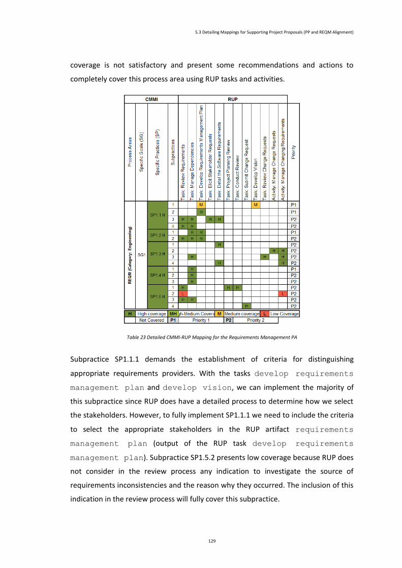
5.3 Detailing Mappings for Supporting Project Proposals (PP and REQM Alignment)
129
coverage is not satisfactory and present some recommendations and actions to
completely cover this process area using RUP tasks and activities.
Table 23 Detailed CMMI-RUP Mapping for the Requirements Management PA
Subpractice SP1.1.1 demands the establishment of criteria for distinguishing
appropriate requirements providers. With the tasks develop requirements
management plan and develop vision, we can implement the majority of
this subpractice since RUP does have a detailed process to determine how we select
the stakeholders. However, to fully implement SP1.1.1 we need to include the criteria
to select the appropriate stakeholders in the RUP artifact requirements
management plan (output of the RUP task develop requirements
management plan). Subpractice SP1.5.2 presents low coverage because RUP does
not consider in the review process any indication to investigate the source of
requirements inconsistencies and the reason why they occurred. The inclusion of this
indication in the review process will fully cover this subpractice.
5 Mapping CMMI and RUP Process Frameworks
130
5.4 Detailing Mappings for Supporting ML2 Projects Execution
Since our second main goal is to understand what kind of support can we expect from
RUP to the execution of software development projects in a CMMI-compliant
perspective, it is extremely important to detail the previous analysis for all the CMMI
ML2 process areas at the subpractices level. The SAM process area is beyond the
scope of our study since this process area is not mandatory for most of the
companies.
As we did to the project proposal, we have considered the two different contexts
defined to the elaboration of project proposals: (1) the context where the team is
completely focused on complying with CMMI recommendations, which means the
team needs to perform all the subpractices; (2) the context where the team is being
constricted to time or cost bounds, which means the team may not be able to
perform all the subpractices. As we said for the elaboration of project proposals,
teams framed in the context #2, should be only focused on what we have called P1
priority subpractices. Teams framed in the context #1 should perform P1, P2 and P3
priority subpractices (see the last column of Table 25). P3 (lower priority) and P2
(medium priority) subpractices may also be skipped, either by the lack of information
or of metrics to be completely covered in the project execution. P3 subpractices are
the first to be skipped, and if the group still without being able to perform the
remaining subpractices (P1 and P2 subpractices), they can skip the P2 subpractices.
P1 (higher priority) subpractices are considered mandatory by us in all project
proposals elaboration. Teams framed in context #2 will develop software products
with less quality than teams framed in context #1. However, it is a minimal difference.
Taking into account the dependencies between ML2 process areas (and between SPs)
we decided to classify these SPs (all subpractices) with priority P1. The following table
(Table 24) presents the process areas that are the target of a dependency from
another ML2 process area. Looking at Table 24, we can see that PP SP1.1, SP1.2,
SP1.4, SP2.1, SP2.2, SP2.3, SP2.4, SP2.5, SP2.6, SP3.1 and SP3.2 will have priority P1.
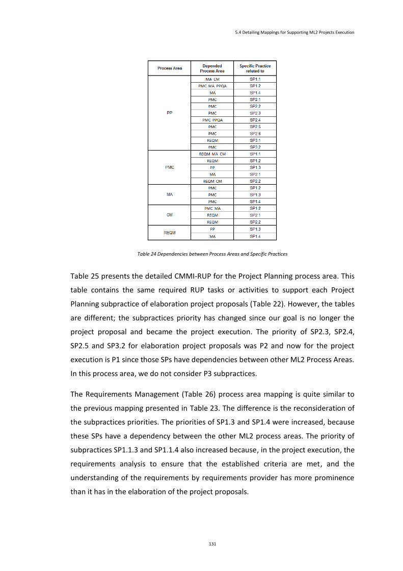
5.4 Detailing Mappings for Supporting ML2 Projects Execution
131
Table 24 Dependencies between Process Areas and Specific Practices
Table 25 presents the detailed CMMI-RUP for the Project Planning process area. This
table contains the same required RUP tasks or activities to support each Project
Planning subpractice of elaboration project proposals (Table 22). However, the tables
are different; the subpractices priority has changed since our goal is no longer the
project proposal and became the project execution. The priority of SP2.3, SP2.4,
SP2.5 and SP3.2 for elaboration project proposals was P2 and now for the project
execution is P1 since those SPs have dependencies between other ML2 Process Areas.
In this process area, we do not consider P3 subpractices.
The Requirements Management (Table 26) process area mapping is quite similar to
the previous mapping presented in Table 23. The difference is the reconsideration of
the subpractices priorities. The priorities of SP1.3 and SP1.4 were increased, because
these SPs have a dependency between the other ML2 process areas. The priority of
subpractices SP1.1.3 and SP1.1.4 also increased because, in the project execution, the
requirements analysis to ensure that the established criteria are met, and the
understanding of the requirements by requirements provider has more prominence
than it has in the elaboration of the project proposals.
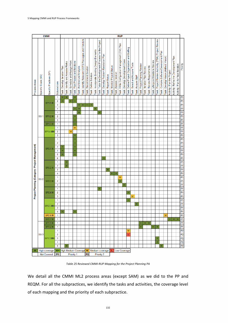
5 Mapping CMMI and RUP Process Frameworks
132
Table 25 Reviewed CMMI-RUP Mapping for the Project Planning PA
We detail all the CMMI ML2 process areas (except SAM) as we did to the PP and
REQM. For all the subpractices, we identify the tasks and activities, the coverage level
of each mapping and the priority of each subpractice.

5.4 Detailing Mappings for Supporting ML2 Projects Execution
133
Table 26 Reviewed CMMI-RUP Mapping for the Requirements Management PA
The Measurements and Analysis and the Project and Monitoring Control also present
high coverage. The Measurements and Analysis process area is composed of eight
Specific Practices, six with high coverage, one (SP2.2) with medium-high coverage and
one (SP2.3) with medium coverage. The SP2.2 presents medium-high coverage since
the tasks Monitor Project Status and Assess Iteration do not
guarantee the execution of an initial analysis of the measurements and
accomplishment of preliminaries results. The SP2.3 presents medium coverage
because none of the RUP tasks covers the subpractices SP2.3.3 and SP2.3.4. RUP does
not have elements that address the need to make the stored measurement data
available only for appropriate groups and personnel, and to prevent the
inappropriate use of the stored information. The subpractices presenting higher
priority are the SP1.2, SP1.3 and SP1.4 subpractices since their priority is imposed by
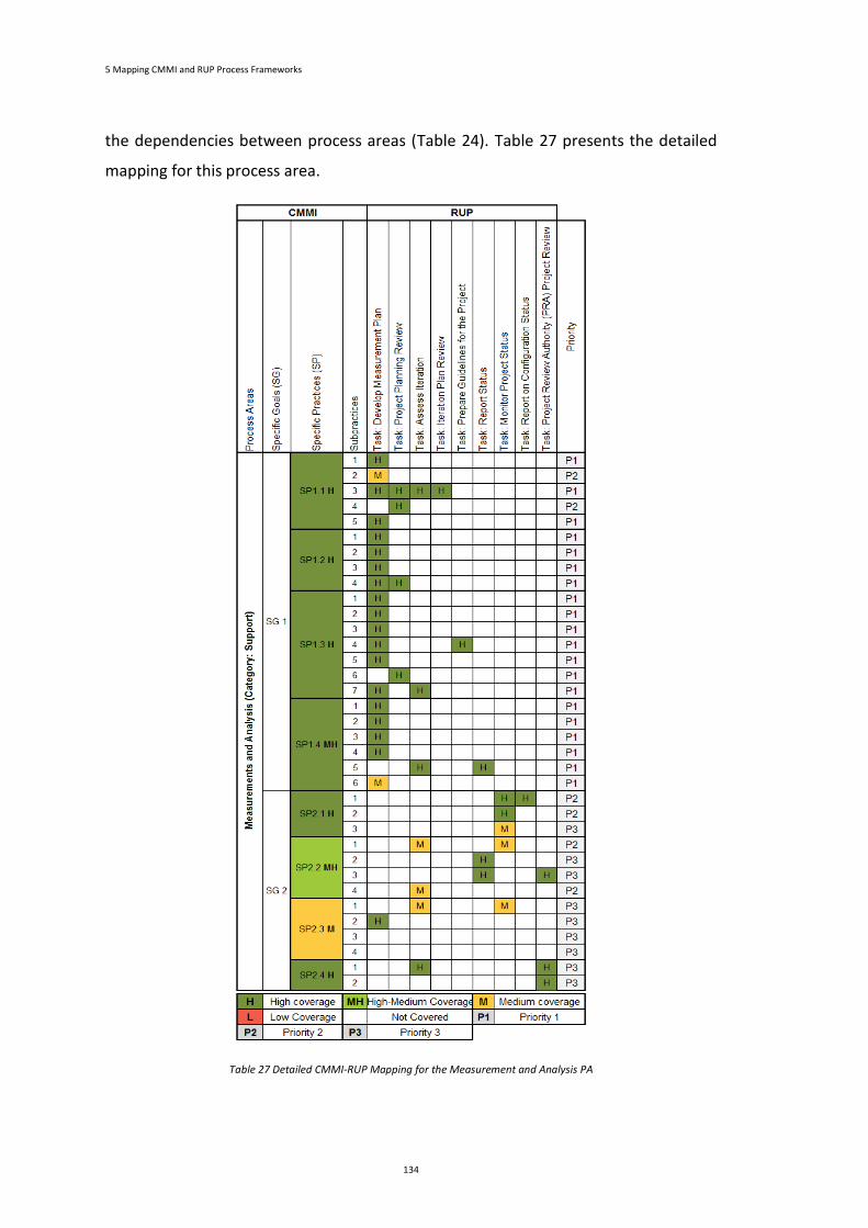
5 Mapping CMMI and RUP Process Frameworks
134
the dependencies between process areas (Table 24). Table 27 presents the detailed
mapping for this process area.
Table 27 Detailed CMMI-RUP Mapping for the Measurement and Analysis PA

5.4 Detailing Mappings for Supporting ML2 Projects Execution
135
The Project Monitoring and Control is composed of two Specific goals. The first goal
(SG1) is composed of seven Specific Practices, four with high coverage and three with
medium-high coverage (SP1.1, SP1.4 and SP1.5). Specific Practice 1.1 is composed of
six subpractices, four of them with high coverage. Subpractice SP.1.1.2 presents
medium coverage because task Develop Measurement Plan does not demand
the inclusion of the project's cost and expended effort in the project metrics. The
other subpractice (SP1.1.5) presents no RUP coverage because RUP do not monitors
the skills of the team members. The SP1.4 has medium-high coverage because two of
its three subpractices (SP1.4.1 and SP1.4.3) are not fully implemented with RUP
elements. With RUP, we cannot guarantee the review of the data management
activities. SP1.5 also presents medium-high coverage because two of its three
subpractices (SP1.5.1 and SP1.5.3) are partially implemented with RUP elements. Task
Report Status does not ensure the review of the stakeholder involvement. The
second goal has three Specific Practices, all with high coverage. The subpractices with
higher priority are the subpractices of SP1.1, SP1.2, SP1.3, SP2.1 and SP2.2. These
subpractices should be performed even if the team has some constrictions because
they monitor the main performance issues of the project. Furthermore, the
dependencies between process areas also impose P1 priority for these Specific
Practices. The detailed CMMI-RUP mapping table for the Project Monitoring and
Control is presented in Annex A.
The remaining ML2 Process Areas are Process and Product Quality Assurance and
Configuration Management. It presents medium-high RUP compliance.
Process and Product Quality Assurance is composed of two Specific Goals each one
with two Specific Practices. SG1 has one Specific Practice (SP1.1) with medium-high
coverage and the other (SP1.2) with high coverage. The SP1.1 is not fully
implemented with RUP because its tasks (in particular the task Assess
Iteration) do not ensure the noncompliance identification and tracking and the
lessons learned identification. The SG2 comprise two Specific Practices presenting
medium coverage. SP2.1 presents medium coverage because RUP tasks do not
address how we can ensure the resolution of noncompliance issues. The medium
coverage of SP2.2 is triggered by the lack of RUP tasks that guarantee the storage and
maintenance of the quality assurance results. This process area does not have
5 Mapping CMMI and RUP Process Frameworks
136
priorities imposed by the dependencies between process areas. This process area has
dependencies from other ML2 process areas, but the other process areas do not have
dependencies from Process and Product Quality Assurance. The detailed CMMI-RUP
mapping table for the Process and Product Quality Assurance is presented in Annex A.
The last process area is the Configuration Management. This process area has three
Specific Goals. The first Specific Goal is divided into three Specific Practices: SP1.1,
SP1.2 and SP1.3 (presenting high coverage). SP1.1 and SP1.2 present medium-high
coverage because RUP tasks do not rigorously define the configuration items,
components, and related work products that should be maintained under
configuration management. RUP does not have mechanisms to create configuration
management reports and guarantee the storage, update, and retrieval of
configuration management records. The Specific Goal 2 and 3 comprise two Specific
Practices each: SP2.1 and SP3.2 with high coverage, and SP2.2 and SP3.1 with low
coverage. The low coverage compliance of those Specific Practices is a consequence
of the absence of RUP tasks that guarantee the control changes of the configuration
items and the establishment and maintenance of configuration management records
describing the configuration items. The detailed CMMI-RUP mapping table for the
Configuration Management is presented in Annex A.
We complement this work with the study of the coverage that each process area can
achieve with the adoption of RUP. To calculate the RUP coverage we start with the
identification of all RUP tasks and activities mapped into each subpractice of the PA
under evaluation. Next, we verify the coverage level for each subpractice. We convert
the coverage levels defined in the previous section into numeric values:
High coverage (H): between 76% and 100%. By default, an H coverage is 100%
(this is the ideal coverage);
Medium-High coverage (MH): between 51% and 75%. By default an MH
coverage is 75%;
Medium coverage (M): between 25% and 50%. By default an M coverage is
50%;
Low coverage (L): between 1% and 25%. By default an L coverage is 25%;
Not covered: the not covered coverage is 0%.

5.4 Detailing Mappings for Supporting ML2 Projects Execution
137
We must verify in which RUP phases each task is performed. We only look at the first
three RUP phases: Inception, Elaboration and Construction. We do not look at the
Transition phase because we are only considering the execution of the software
development. Then, we determine the subpractice coverage in each RUP phase, by
calculating the average of the tasks coverage. We must take into consideration that
RUP tasks and activities are not performed in all the RUP phases, some tasks are
performed only in the Inception, some tasks only in the Elaboration, other tasks are
performed only in two phases, and so on. We calculate the coverage assuming that
the first time a task is performed it achieves its ideal coverage. It will be explained in
detail with a set of examples.
To illustrate this study we will describe how we RUP calculate the coverage of Project
Planning SP1.1.1, SP1.1.4 and SP1.4.1 (see Table 28). Subpractice SP1.1.1 is mapped
into the tasks Develop Iteration Plan, Identify and Assess Risks
and Plan Phases and Iterations. The coverage level for this subpractice,
SP1.1.1, is high coverage, so, these tasks present RUP coverage of 100%. Then, we
verify in which RUP phases these tasks are performed. The tasks Develop
Iteration Plan and Identify and Assess Risks are performed in all
RUP phases we are considering. The task Plan Phases and Iterations is
only performed in the Inception and Elaboration phases. Therefore, this subpractice
presents RUP coverage of 100% in the three RUP phases under evaluation. The RUP
coverage is the same in all phases because the tasks mapped into this subpractice are
all performed for the first time in the same RUP phase (the Inception).
The subpractice SP1.1.4 is mapped into the tasks Plan Phases and
Iterations, Architectural Analysis and Incorporate Existing
Design Elements. The coverage of this subpractice is high. The tasks Plan
Phases and Iterations and Architectural Analysis are performed
in the Inception and Elaboration phases, and the task Incorporate Existing
Design Elements is only performed in Elaboration phase. This subpractice is
mapped into three tasks, but two of the tasks are performed in the Inception phase
which means we consider a RUP coverage of 67%.
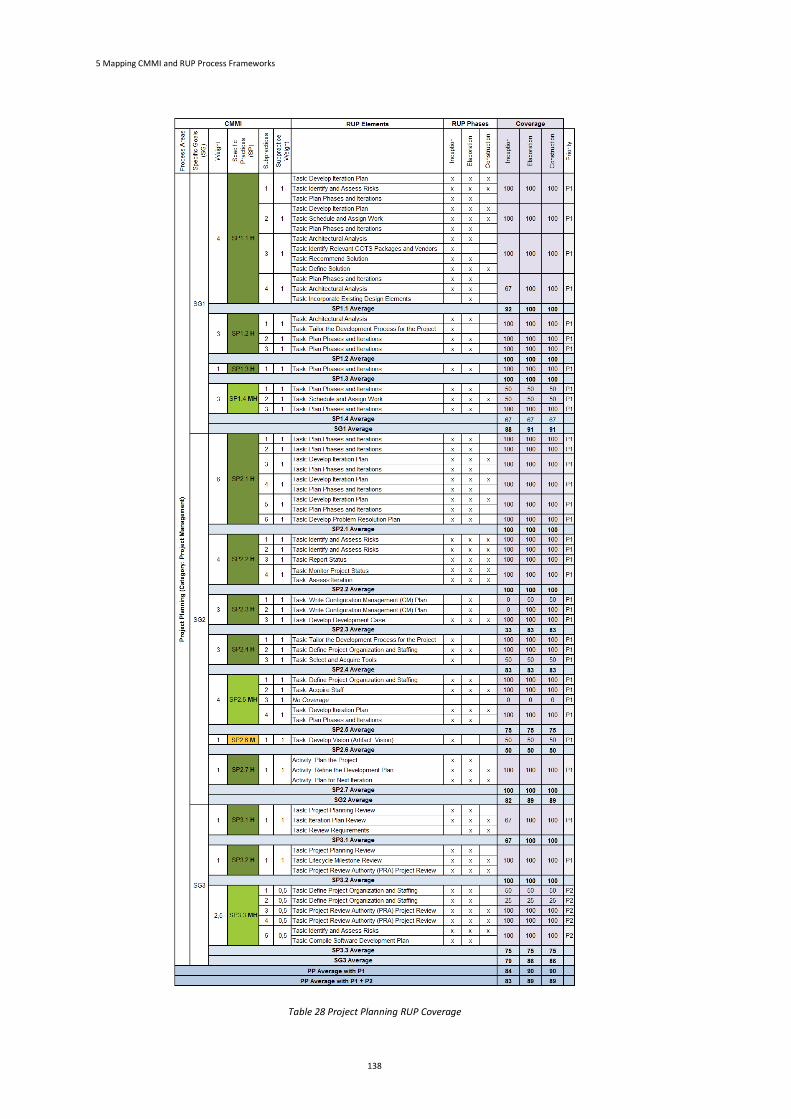
5 Mapping CMMI and RUP Process Frameworks
138
Table 28 Project Planning RUP Coverage
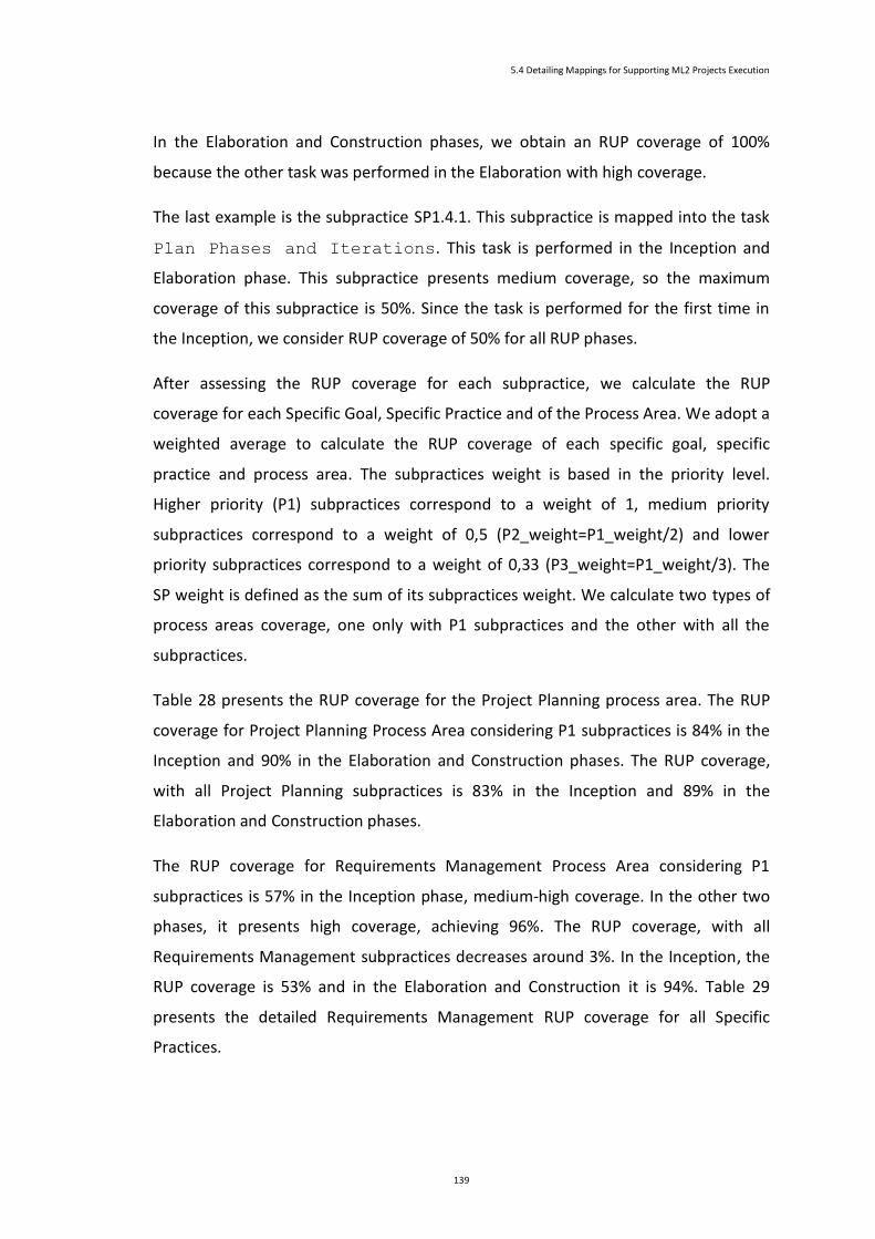
5.4 Detailing Mappings for Supporting ML2 Projects Execution
139
In the Elaboration and Construction phases, we obtain an RUP coverage of 100%
because the other task was performed in the Elaboration with high coverage.
The last example is the subpractice SP1.4.1. This subpractice is mapped into the task
Plan Phases and Iterations. This task is performed in the Inception and
Elaboration phase. This subpractice presents medium coverage, so the maximum
coverage of this subpractice is 50%. Since the task is performed for the first time in
the Inception, we consider RUP coverage of 50% for all RUP phases.
After assessing the RUP coverage for each subpractice, we calculate the RUP
coverage for each Specific Goal, Specific Practice and of the Process Area. We adopt a
weighted average to calculate the RUP coverage of each specific goal, specific
practice and process area. The subpractices weight is based in the priority level.
Higher priority (P1) subpractices correspond to a weight of 1, medium priority
subpractices correspond to a weight of 0,5 (P2_weight=P1_weight/2) and lower
priority subpractices correspond to a weight of 0,33 (P3_weight=P1_weight/3). The
SP weight is defined as the sum of its subpractices weight. We calculate two types of
process areas coverage, one only with P1 subpractices and the other with all the
subpractices.
Table 28 presents the RUP coverage for the Project Planning process area. The RUP
coverage for Project Planning Process Area considering P1 subpractices is 84% in the
Inception and 90% in the Elaboration and Construction phases. The RUP coverage,
with all Project Planning subpractices is 83% in the Inception and 89% in the
Elaboration and Construction phases.
The RUP coverage for Requirements Management Process Area considering P1
subpractices is 57% in the Inception phase, medium-high coverage. In the other two
phases, it presents high coverage, achieving 96%. The RUP coverage, with all
Requirements Management subpractices decreases around 3%. In the Inception, the
RUP coverage is 53% and in the Elaboration and Construction it is 94%. Table 29
presents the detailed Requirements Management RUP coverage for all Specific
Practices.
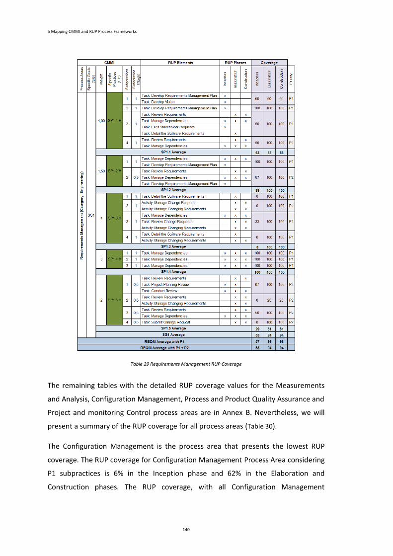
5 Mapping CMMI and RUP Process Frameworks
140
Table 29 Requirements Management RUP Coverage
The remaining tables with the detailed RUP coverage values for the Measurements
and Analysis, Configuration Management, Process and Product Quality Assurance and
Project and monitoring Control process areas are in Annex B. Nevertheless, we will
present a summary of the RUP coverage for all process areas (Table 30).
The Configuration Management is the process area that presents the lowest RUP
coverage. The RUP coverage for Configuration Management Process Area considering
P1 subpractices is 6% in the Inception phase and 62% in the Elaboration and
Construction phases. The RUP coverage, with all Configuration Management
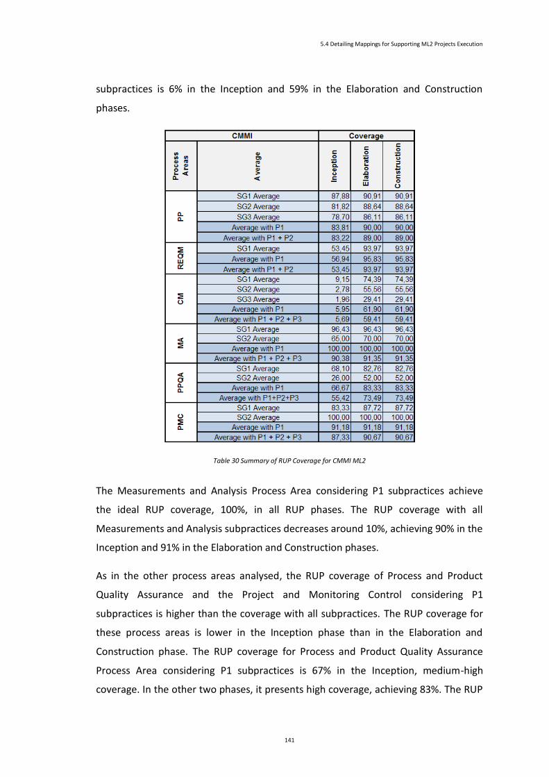
5.4 Detailing Mappings for Supporting ML2 Projects Execution
141
subpractices is 6% in the Inception and 59% in the Elaboration and Construction
phases.
Table 30 Summary of RUP Coverage for CMMI ML2
The Measurements and Analysis Process Area considering P1 subpractices achieve
the ideal RUP coverage, 100%, in all RUP phases. The RUP coverage with all
Measurements and Analysis subpractices decreases around 10%, achieving 90% in the
Inception and 91% in the Elaboration and Construction phases.
As in the other process areas analysed, the RUP coverage of Process and Product
Quality Assurance and the Project and Monitoring Control considering P1
subpractices is higher than the coverage with all subpractices. The RUP coverage for
these process areas is lower in the Inception phase than in the Elaboration and
Construction phase. The RUP coverage for Process and Product Quality Assurance
Process Area considering P1 subpractices is 67% in the Inception, medium-high
coverage. In the other two phases, it presents high coverage, achieving 83%. The RUP

5 Mapping CMMI and RUP Process Frameworks
142
coverage, with all Process and Product Quality Assurance is 55% in the Inception and
73% in the Elaboration and Construction phases. The RUP coverage for Project and
Monitoring Control Process Area considering P1 subpractices is 91% in the Inception,
Elaboration and Construction phases. The RUP coverage, with all subpractices is 87%
in the Inception and 91% in the Elaboration and Construction phases.
5.5 Evolution of CMMI-RUP Tasks Accomplishment
As mentioned before, RUP framework defines a set of tasks, which have to be
performed to execute a software development project. RUP is divided into four
sequential phases. In this work, we are only concerned with three of those phases:
Inception, Elaboration and Construction phase. The tasks defined by RUP will not be
performed in all phases. In each phase, we have to perform a subset of the defined
RUP tasks. Therefore, the accomplishment distribution of each phase and task is not
the same.
We decide to calculate the Accomplishment distribution of the CMMI-RUP mapping
elements. For the CMMI-RUP mapping tasks, we identify eight different
accomplishment distributions. We identify each distribution as Type A, Type B, …,
Type H. We will not focus in this study on the effort of each task, but on the number
of times each tasks is performed in the workflow of each analysed phase.
For each Accomplishment Type we detail the tasks that have such distribution, the
phases where they are performed, and the percentage of accomplishment in each
phase as well as the accumulated accomplishment in the end of each phase. Since we
are only looking for the Inception, Elaboration and Construction phase we consider
that the accumulated accomplishment of each task in the end of the Construction
phase has to be 100%.
Figure 25 presents the detail of the Type A accomplishment distribution. Fourteen
tasks have this type of accomplishment distribution. We will pick the Development
Iteration Plan as an example to describe this Accomplishment Type. This task
is performed one time in each phase. It is performed one time in the Inception,
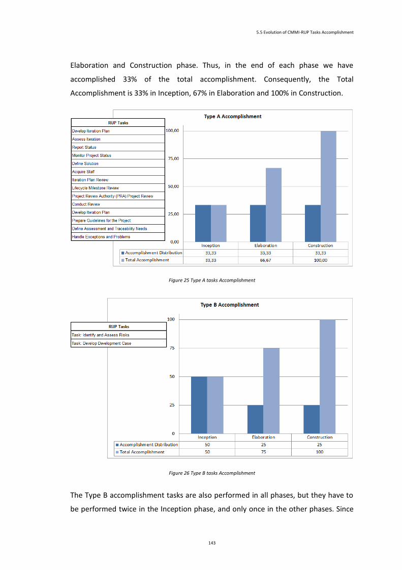
5.5 Evolution of CMMI-RUP Tasks Accomplishment
143
Elaboration and Construction phase. Thus, in the end of each phase we have
accomplished 33% of the total accomplishment. Consequently, the Total
Accomplishment is 33% in Inception, 67% in Elaboration and 100% in Construction.
Figure 25 Type A tasks Accomplishment
Figure 26 Type B tasks Accomplishment
The Type B accomplishment tasks are also performed in all phases, but they have to
be performed twice in the Inception phase, and only once in the other phases. Since
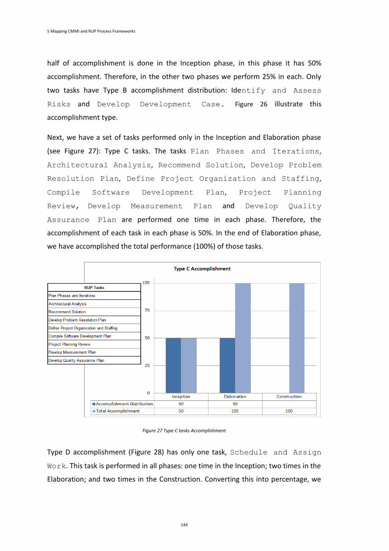
5 Mapping CMMI and RUP Process Frameworks
144
half of accomplishment is done in the Inception phase, in this phase it has 50%
accomplishment. Therefore, in the other two phases we perform 25% in each. Only
two tasks have Type B accomplishment distribution: Identify and Assess
Risks and Develop Development Case. Figure 26 illustrate this
accomplishment type.
Next, we have a set of tasks performed only in the Inception and Elaboration phase
(see Figure 27): Type C tasks. The tasks Plan Phases and Iterations,
Architectural Analysis, Recommend Solution, Develop Problem
Resolution Plan, Define Project Organization and Staffing,
Compile Software Development Plan, Project Planning
Review, Develop Measurement Plan and Develop Quality
Assurance Plan are performed one time in each phase. Therefore, the
accomplishment of each task in each phase is 50%. In the end of Elaboration phase,
we have accomplished the total performance (100%) of those tasks.
Figure 27 Type C tasks Accomplishment
Type D accomplishment (Figure 28) has only one task, Schedule and Assign
Work. This task is performed in all phases: one time in the Inception; two times in the
Elaboration; and two times in the Construction. Converting this into percentage, we
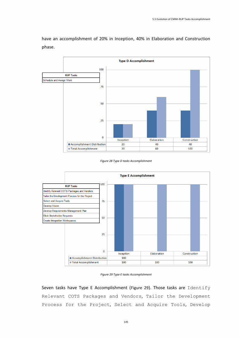
5.5 Evolution of CMMI-RUP Tasks Accomplishment
145
have an accomplishment of 20% in Inception, 40% in Elaboration and Construction
phase.
Figure 28 Type D tasks Accomplishment
Figure 29 Type E tasks Accomplishment
Seven tasks have Type E Accomplishment (Figure 29). Those tasks are Identify
Relevant COTS Packages and Vendors, Tailor the Development
Process for the Project, Select and Acquire Tools, Develop

5 Mapping CMMI and RUP Process Frameworks
146
Vision, Develop Requirements Management Plan, Elicit
Stakeholder Requests and Create Integration Workspaces. They
are performed only once in a software development project, in the Inception phase.
We achieve 100% accomplishment in the end of the first phase.
Figure 30 Type F tasks Accomplishment
Figure 31 Type G tasks Accomplishment
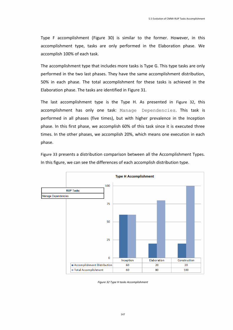
5.5 Evolution of CMMI-RUP Tasks Accomplishment
147
Type F accomplishment (Figure 30) is similar to the former. However, in this
accomplishment type, tasks are only performed in the Elaboration phase. We
accomplish 100% of each task.
The accomplishment type that includes more tasks is Type G. This type tasks are only
performed in the two last phases. They have the same accomplishment distribution,
50% in each phase. The total accomplishment for these tasks is achieved in the
Elaboration phase. The tasks are identified in Figure 31.
The last accomplishment type is the Type H. As presented in Figure 32, this
accomplishment has only one task: Manage Dependencies. This task is
performed in all phases (five times), but with higher prevalence in the Inception
phase. In this first phase, we accomplish 60% of this task since it is executed three
times. In the other phases, we accomplish 20%, which means one execution in each
phase.
Figure 33 presents a distribution comparison between all the Accomplishment Types.
In this figure, we can see the differences of each accomplish distribution type.
Figure 32 Type H tasks Accomplishment
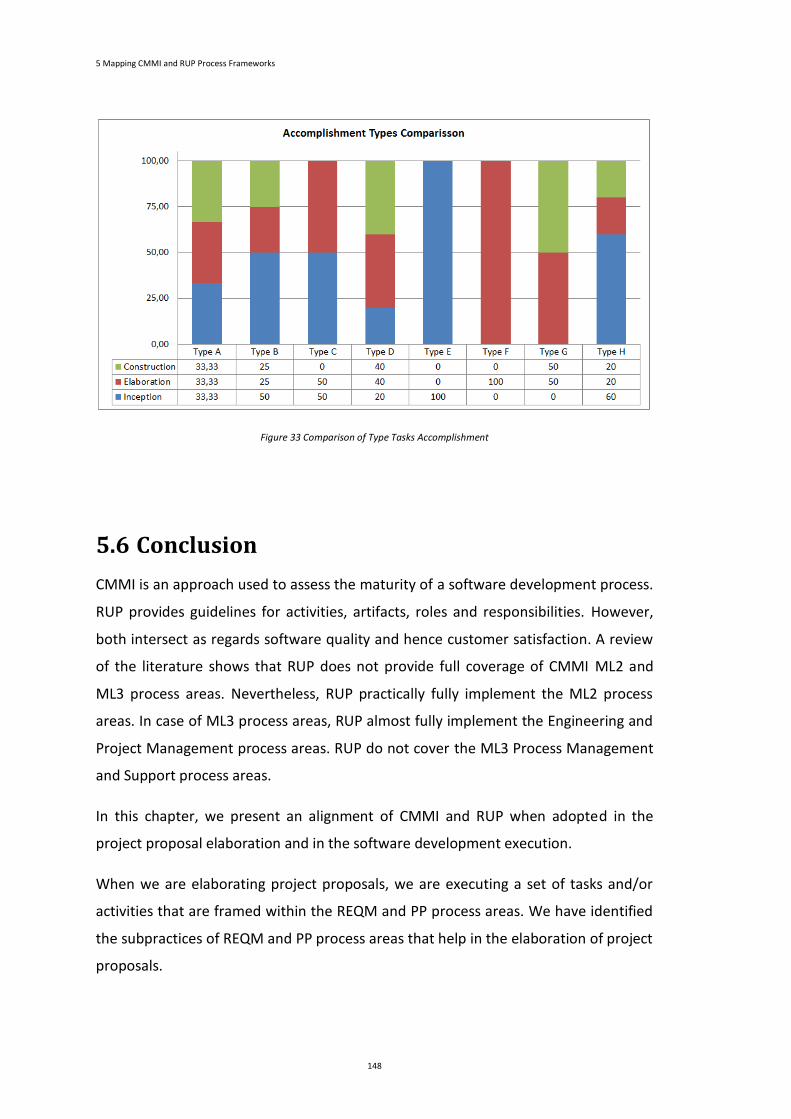
5 Mapping CMMI and RUP Process Frameworks
148
Figure 33 Comparison of Type Tasks Accomplishment
5.6 Conclusion
CMMI is an approach used to assess the maturity of a software development process.
RUP provides guidelines for activities, artifacts, roles and responsibilities. However,
both intersect as regards software quality and hence customer satisfaction. A review
of the literature shows that RUP does not provide full coverage of CMMI ML2 and
ML3 process areas. Nevertheless, RUP practically fully implement the ML2 process
areas. In case of ML3 process areas, RUP almost fully implement the Engineering and
Project Management process areas. RUP do not cover the ML3 Process Management
and Support process areas.
In this chapter, we present an alignment of CMMI and RUP when adopted in the
project proposal elaboration and in the software development execution.
When we are elaborating project proposals, we are executing a set of tasks and/or
activities that are framed within the REQM and PP process areas. We have identified
the subpractices of REQM and PP process areas that help in the elaboration of project
proposals.
5.6 Conclusion
149
In the software development implementation, we are also executing a set of tasks
and/or activities that fulfil the CMMI ML2 process areas. We have identified the
subpractices of all ML2 process areas (except SAM) that are covered by RUP tasks
and/or activities. The theoretical coverage level for each process area was identified.
The RUP tasks that are mapped into a process area were analysed to verify their
accomplishment distribution over the Inception, Elaboration and Construction phase.
This accomplishment distribution study allows the comprehension of the theoretical
coverage evolution over the analysed RUP phases.

Chapter 6
Case Studies Analysis
Chapter Contents
6 Case Studies Analysis .....................................................................................................................153
6.1 Introduction .............................................................................................................................153
6.2 Case Study I - Assessing RUP Reduced Model ...........................................................................154
6.3 Case Study II - Assessing RUP Support for Project Proposals ....................................................156
6.4 Case Study III - Assessing RUP Support for ML2 Projects Execution ..........................................163
6.5 Conclusion ...............................................................................................................................173

152
153
6
Case Studies Analysis
In this chapter, the case studies developed to assess the contributions of this thesis
are analysed. The case studies were developed in an educational environment and in
an industrial setting. The case studies are assessed with the CMMI ML2 in order to
illustrate the main contributions of the previous chapters: the Reduced Model, the
CMMI-RUP mapping for the project proposal elaboration and the CMMI-RUP mapping
for the software development execution. The case study results are compared with
the theoretical results presented previously.
6.1 Introduction
To assess our contributions, a set of case studies were implemented. The case studies
were developed in an educational environment and one in an industrial setting. The
educational environment case studies were composed of a set of teams consisting of
second year students from the undergraduate degree in Information Systems and
Technology in University of Minho.
The Case Study I was developed to initially assess the effectiveness of the RUP
Reduced Model configuration using CMMI-DEV ML2 as a reference model.

6 Case Studies Analysis
154
In Case Study II, the usefulness of CMMI-RUP mapping will be illustrated in two
different studies, where we interpret the results obtained in terms of the teams’
performance to elaborate project proposals.
The last case study, Case Study III, extends the effort of the previous case study, by
assessing the usefulness of CMMI-RUP mapping and interpreting the results obtained
in terms of the teams’ performance to execute software development projects.
6.2 Case Study I - Assessing RUP Reduced Model
A case study was developed to assess the reduced model. It involved seven
development software teams. The software project developed by the teams was
requested by a real customer that provided all the information about the
organization and interacted directly with the teams.
The teams consisted of second year students of the course 8604N5 Software System
Development (SSD) from the undergraduate degree in Information Systems and
Technology in University of Minho. The teams had between 13 and 17 people (1 team
with 13, 3 teams with 14, 2 teams with 16 and 1 with 17). Each team received a
sequential identification number (Team 1, Team 2, .., Team 7) and the description of
the customer problem. Two teams were randomly chosen not to adopt the RUP
reduced model (we call these two teams the "Control Teams" and they follow the full
RUP framework) while the other five teams followed the guidelines established by
the RUP reduced model, executing the phases of inception, elaboration and
construction. The project lasted 3 months. The control teams did not follow any kind
of guidelines for organizing themselves in term of roles/responsibilities/team
organization.
The teams following RUP used the eight roles proposed by the reduced model. Due to
the complexity of the system, we have decided to instantiate two of the optional sub-
roles referred in Figure 7: System Analyst (that corresponds to a part of the

6.2 Case Study I - Assessing RUP Reduced Model I
155
responsibilities of the Project Manager) and Software Architect (that corresponds to a
part of the responsibilities of the Integrator). Team organization was as follows:
• 1 Project Manager;
• 1 or 2 System Analysts;
• 1 or 2 Integrators;
• 1 Software Architect;
• 1 Project Reviewer;
• 1 Process Engineer;
• 4 to 6 Implementers (programmers);
• 1 System Administrator;
• 1 Test Manager and;
• 1 System Tester.
The assessment of the reduced model was conducted by adopting the CMMI-DEV
v1.2 ML2 reference model. With the exception of SAM (Supplier Agreement
Management), all the other process areas had been assessed.
The diagnostic performed within each of the teams adopted the following five steps:
1. a survey with 125 questions was developed based on generic and specific
practices of CMMI-DEV v1.2 ML2;
2. the developed survey was assessed by 2 experts in SCAMPI model. The
resulting suggestions were incorporated into the final version of the
survey;
3. a survey was answered by each of the project managers of the 7 teams;
4. each team element was characterize by mean of an online survey to
collect information about age, sex, RUP role performed (except for the
control teams), and the number of working hours. The survey response
was 100%;
5. the RUP work products generated by each team were assessed in terms of
their existence. This has allowed the validation of the data obtained from
step 3 by each one of the project managers.
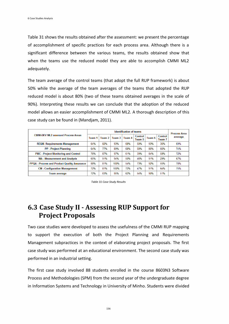
6 Case Studies Analysis
156
Table 31 shows the results obtained after the assessment: we present the percentage
of accomplishment of specific practices for each process area. Although there is a
significant difference between the various teams, the results obtained show that
when the teams use the reduced model they are able to accomplish CMMI ML2
adequately.
The team average of the control teams (that adopt the full RUP framework) is about
50% while the average of the team averages of the teams that adopted the RUP
reduced model is about 80% (two of these teams obtained averages in the scale of
90%). Interpreting these results we can conclude that the adoption of the reduced
model allows an easier accomplishment of CMMI ML2. A thorough description of this
case study can be found in (Mandjam, 2011).
Table 31 Case Study Results
6.3 Case Study II - Assessing RUP Support for Project Proposals
Two case studies were developed to assess the usefulness of the CMMI RUP mapping
to support the execution of both the Project Planning and Requirements
Management subpractices in the context of elaborating project proposals. The first
case study was performed at an educational environment. The second case study was
performed in an industrial setting.
The first case study involved 88 students enrolled in the course 8603N3 Software
Process and Methodologies (SPM) from the second year of the undergraduate degree
in Information Systems and Technology in University of Minho. Students were divided
6.3 Case Study II - Assessing RUP Support for Project Proposals
157
into 19 development software teams, each one receiving a sequential identification
number (Team 1, Team 2 ... Team 19).
The software project to be developed was requested by a real customer that
provided all the information about the organization and interacted directly with the
teams. The main goal of the teams was to elaborate a project proposal to solve the
customer’s problem, by producing one report. The report should address the
following issues: the main features of the technical software solution and the cost
and duration of the project. Control team 15 was randomly chosen not to follow the
RUP guidelines (this team is referred as "control team"). The other teams are referred
in this section as "regular teams".
The assessment of the teams’ performance adopted the following seven steps: (1) A
survey with 31 questions was developed based on REQM and PP subpractices; (2) The
developed survey was assessed by two experts in SCAMPI model. The resulting
suggestions were incorporated into the final version of the survey; (3) Survey was
answered by each element of the 19 teams; (4) Each team element was characterized
by mean of an online survey to collect information about age, sex, RUP role
performed. The survey response was 100%; (5) The RUP work products generated by
each team were assessed in terms of their existence. This has allowed the validation
of the data obtained from step 3 by each one of the project managers; (6) Direct
observation of the teams’ work (during their regular meetings) to perceive their
difficulties and doubts; (7) Analysis of the teams’ academic performance based on the
marks given by the SPM course instructors.
Table 32 shows the results obtained after the assessment. For each team, we present
the coverage level observed for each subpractice, the corresponding average for each
SP of REQM and PP process areas and the process area average. The coverage level
was converted into numeric values: high coverage (H) corresponds to 100%; medium-
high coverage (MH) corresponds to 75%; medium coverage (M) corresponds to 50%;
low coverage (L) corresponds to 25%, and no coverage (N) correspond to 0%. We
have adopted a weighted average to calculate the coverage of each SP and PA.
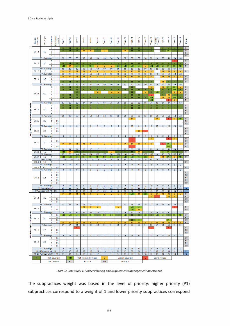
6 Case Studies Analysis
158
Table 32 Case study 1: Project Planning and Requirements Management Assessment
The subpractices weight was based in the level of priority: higher priority (P1)
subpractices correspond to a weight of 1 and lower priority subpractices correspond
6.3 Case Study II - Assessing RUP Support for Project Proposals
159
to a weight of 0,5 (P2_weight=P1_weight/2). The SP weight was defined as the sum
of its subpractices weight.
In general, teams implemented mainly the P1 subpractices. However, some teams
have implemented also some P2 subpractices. In what considers the PP process area,
we can observe similar results across the teams: averages with P1 and P2
subpractices are between 38% and 45%, and averages with only P1 subpractices are
between 44% and 56%.
Taking into account the results of the control team, we can conclude that PP process
area was reasonably performed by the students. However, the results for the REQM
process area were quite weak, which means that the teams were more focused on
the planning of the project rather than on the elicitation and description of the
requirements for the demanded solution. This is also a quite frequent behaviour
observed in the industrial practitioners (case study 2 confirms this). The teams have
focused their work mainly on the elaboration of the Product Breakdown Structure
(PBS) and the Work Breakdown Structure (WBS).
For the REQM process area averages with P1 and P2 subpractices are between 11%
and 30%, and averages with only P1 subpractices are between 13% and 38%. These
results are quite disappointing from the perspective of the quality of the teams work.
By using the surveys, we concluded that the teams have neglected essential RUP
tasks needed to ensure the complete coverage of the required subpractices to the
elaboration of project proposals. With the direct observation, we could perceive a
quite different set of activities performed by each regular team that may justify the
results obtained for the REQM process area, by the considerable RUP tailoring effort
that each team had to perform. The control team performed two of the four P1
subpractices and two P2 subpractices. The results of the regular teams and the
control team are quite similar. Even not using RUP, the control team performed the
elicitation and description of the requirements similarly to the other teams. These
similarities demonstrate the pertinence of explicitly informing practitioners about
two different levels of priorities for REQM subpractices, to help them better decide
what subpractices to perform even in strongly constricted contexts for the
elaboration of project proposals.
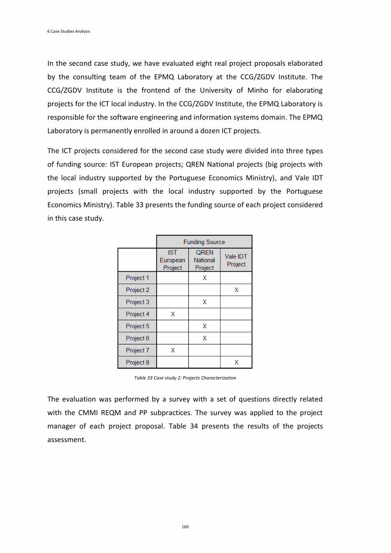
6 Case Studies Analysis
160
In the second case study, we have evaluated eight real project proposals elaborated
by the consulting team of the EPMQ Laboratory at the CCG/ZGDV Institute. The
CCG/ZGDV Institute is the frontend of the University of Minho for elaborating
projects for the ICT local industry. In the CCG/ZGDV Institute, the EPMQ Laboratory is
responsible for the software engineering and information systems domain. The EPMQ
Laboratory is permanently enrolled in around a dozen ICT projects.
The ICT projects considered for the second case study were divided into three types
of funding source: IST European projects; QREN National projects (big projects with
the local industry supported by the Portuguese Economics Ministry), and Vale IDT
projects (small projects with the local industry supported by the Portuguese
Economics Ministry). Table 33 presents the funding source of each project considered
in this case study.
Table 33 Case study 2: Projects Characterization
The evaluation was performed by a survey with a set of questions directly related
with the CMMI REQM and PP subpractices. The survey was applied to the project
manager of each project proposal. Table 34 presents the results of the projects
assessment.
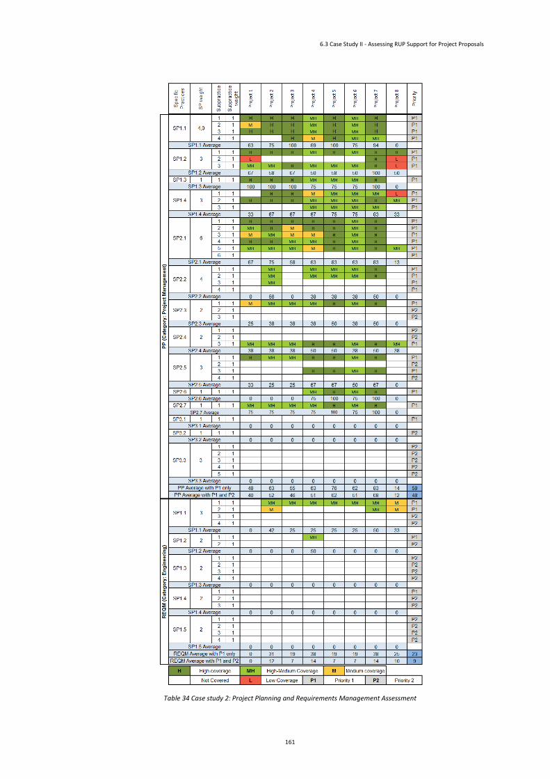
6.3 Case Study II - Assessing RUP Support for Project Proposals
161
Table 34 Case study 2: Project Planning and Requirements Management Assessment

6 Case Studies Analysis
162
When we consider the PP process area, we can observe similar results across the
projects: averages with P1 and P2 subpractices are between 12% and 68%, and
averages with only P1 subpractices are between 14% and 83%.
The elaboration of project proposals for IST European calls is more exhaustive and
demanding than for other calls. Those projects are usually more complex, have longer
duration, higher number of partners and are usually focused in a mix of applied
research and technology transfer. Therefore, the average of PP process area for those
projects is much higher than the QREN national projects and the Vale IDT projects.
In what concerns the REQM process area, we can observe a decrease of effort when
compared with the PP process area. Across the 8 projects, we have obtained averages
for P1 and P2 subpractices between 0% and 14%, and averages with only P1
subpractices between 0% and 38%.
As stated before, the industrial practitioners are also more focused on the planning of
the project rather than on the elicitation and description of the requirements; so, the
results for the REQM process area were also quite weak as in the case study 1. As in
the PP subpractices, the results for the REQM process area show that the IST
European projects have a better result since, in these projects, a proper definition of
the project scope is fundamental to achieving a successful project.
When comparing the results of case study 1 and case study 2, we can conclude that
the performance of case study 2 is better in both the calculated averages, P1 and
P1+P2 subpractices (see Figure 34). Since the project planning tasks are directly
related to the budget to be approved, it is completely understandable why in real
projects the subpractices of the PP process area are better performed than in the
academic environment.
When we analyse the REQM process area, we obtain two different situations:
• case study 1 performed better in P1+P2 subpractices;
• case study 2 only performed P1 subpractices. We believe that, in
constricted contexts of the elaboration of project proposals, industrial
practitioners are more effective in selecting and performing higher priority
subpractices since they know that the elicitation and the description of
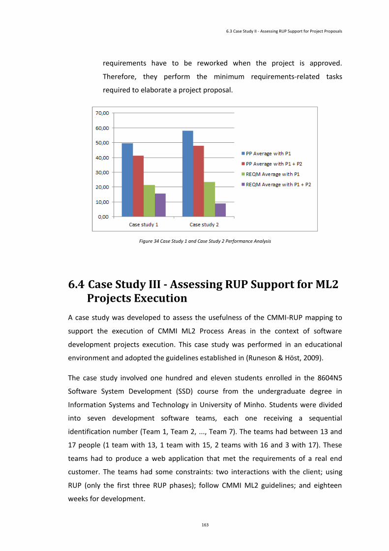
6.3 Case Study II - Assessing RUP Support for Project Proposals
163
requirements have to be reworked when the project is approved.
Therefore, they perform the minimum requirements-related tasks
required to elaborate a project proposal.
Figure 34 Case Study 1 and Case Study 2 Performance Analysis
6.4 Case Study III - Assessing RUP Support for ML2 Projects Execution
A case study was developed to assess the usefulness of the CMMI-RUP mapping to
support the execution of CMMI ML2 Process Areas in the context of software
development projects execution. This case study was performed in an educational
environment and adopted the guidelines established in (Runeson & Höst, 2009).
The case study involved one hundred and eleven students enrolled in the 8604N5
Software System Development (SSD) course from the undergraduate degree in
Information Systems and Technology in University of Minho. Students were divided
into seven development software teams, each one receiving a sequential
identification number (Team 1, Team 2, ..., Team 7). The teams had between 13 and
17 people (1 team with 13, 1 team with 15, 2 teams with 16 and 3 with 17). These
teams had to produce a web application that met the requirements of a real end
customer. The teams had some constraints: two interactions with the client; using
RUP (only the first three RUP phases); follow CMMI ML2 guidelines; and eighteen
weeks for development.
6 Case Studies Analysis
164
All teams had attended a previous course where they were exposed to the RUP concepts.
One team (Team 1) was randomly chosen not to adopt the RUP (we call this team the
"Control Team") while the other six teams followed the guidelines established by the
RUP, executing the phases of inception, elaboration and construction. The control
team did not follow any kind of guidelines for organizing themselves in term of
roles/responsibilities/team organization.
The students have four assessment milestones of execution and evaluation:
• Assessment Milestone 1 (M1): relates to the initial project planning, which
is part of the Inception Phase;
• Assessment Milestone 2 (M2): relates to the Inception Phase;
• Assessment Milestone 3 (M3): relates to the Elaboration Phase;
• Assessment Milestone 4 (M4): relates to the Construction Phase.
The assessment of the teams’ performance adopted the following two steps: (1)
Documental analysis of the produced artifacts to detect compliance with the
subpractices of the ML2 process areas. SAM process area is out of the project scope;
(2) Elaboration of a survey at the end of each assessment milestone, to check the
status of the teams and the team members perception of CMMI practices.
For each team, we calculate the coverage level observed for each subpractice, the
corresponding average for each specific practice of CMMI ML2 process areas and the
process area average. As we did in the previous case study and in section 5.4, the
coverage level was converted into numeric values: high coverage (H) corresponds to
100%; medium-high coverage (MH) corresponds to 75%; medium coverage (M)
corresponds to 50%; low coverage (L) corresponds to 25%, and no coverage (N)
correspond to 0%. The specific practice and process area coverage was calculated
using the weighted average. The subpractices weight was based in the level of
priority: P1 subpractices correspond to a weight of 1, P2 subpractices correspond to a
weight of 0,5 (P2_weight=P1_weight/2) and P3 subpractices correspond to a weight
of 0,33 (P3_weight=P1_weight/3). The specific practice weight was defined as the
sum of its subpractices weight.
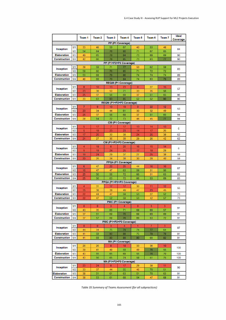
6.4 Case Study III - Assessing RUP Support for ML2 Projects Execution
165
Table 35 Summary of Teams Assessment (for all subpractices)
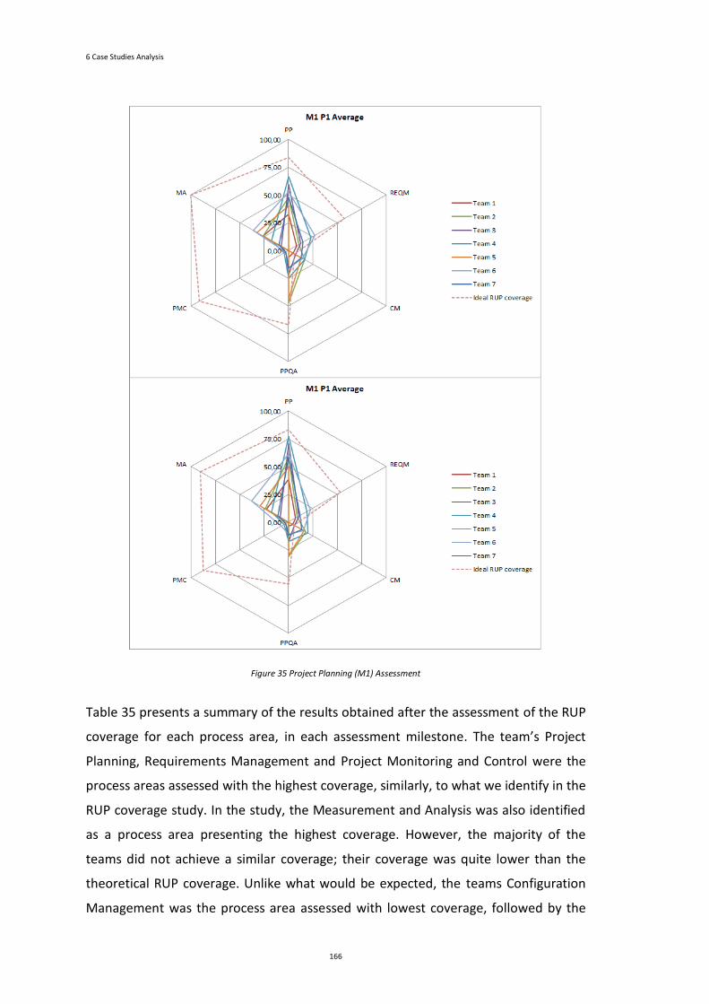
6 Case Studies Analysis
166
Figure 35 Project Planning (M1) Assessment
Table 35 presents a summary of the results obtained after the assessment of the RUP
coverage for each process area, in each assessment milestone. The team’s Project
Planning, Requirements Management and Project Monitoring and Control were the
process areas assessed with the highest coverage, similarly, to what we identify in the
RUP coverage study. In the study, the Measurement and Analysis was also identified
as a process area presenting the highest coverage. However, the majority of the
teams did not achieve a similar coverage; their coverage was quite lower than the
theoretical RUP coverage. Unlike what would be expected, the teams Configuration
Management was the process area assessed with lowest coverage, followed by the
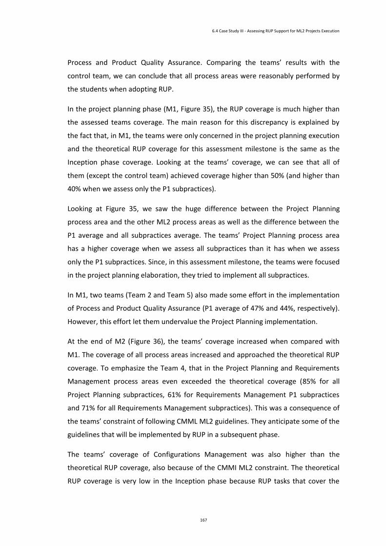
6.4 Case Study III - Assessing RUP Support for ML2 Projects Execution
167
Process and Product Quality Assurance. Comparing the teams’ results with the
control team, we can conclude that all process areas were reasonably performed by
the students when adopting RUP.
In the project planning phase (M1, Figure 35), the RUP coverage is much higher than
the assessed teams coverage. The main reason for this discrepancy is explained by
the fact that, in M1, the teams were only concerned in the project planning execution
and the theoretical RUP coverage for this assessment milestone is the same as the
Inception phase coverage. Looking at the teams’ coverage, we can see that all of
them (except the control team) achieved coverage higher than 50% (and higher than
40% when we assess only the P1 subpractices).
Looking at Figure 35, we saw the huge difference between the Project Planning
process area and the other ML2 process areas as well as the difference between the
P1 average and all subpractices average. The teams’ Project Planning process area
has a higher coverage when we assess all subpractices than it has when we assess
only the P1 subpractices. Since, in this assessment milestone, the teams were focused
in the project planning elaboration, they tried to implement all subpractices.
In M1, two teams (Team 2 and Team 5) also made some effort in the implementation
of Process and Product Quality Assurance (P1 average of 47% and 44%, respectively).
However, this effort let them undervalue the Project Planning implementation.
At the end of M2 (Figure 36), the teams’ coverage increased when compared with
M1. The coverage of all process areas increased and approached the theoretical RUP
coverage. To emphasize the Team 4, that in the Project Planning and Requirements
Management process areas even exceeded the theoretical coverage (85% for all
Project Planning subpractices, 61% for Requirements Management P1 subpractices
and 71% for all Requirements Management subpractices). This was a consequence of
the teams’ constraint of following CMML ML2 guidelines. They anticipate some of the
guidelines that will be implemented by RUP in a subsequent phase.
The teams’ coverage of Configurations Management was also higher than the
theoretical RUP coverage, also because of the CMMI ML2 constraint. The theoretical
RUP coverage is very low in the Inception phase because RUP tasks that cover the

6 Case Studies Analysis
168
Configurations Management subpractices have Type F and Type G Accomplishment
distribution.
Figure 36 Inception(M2) Assessment
The M3 results are presented in Figure 37. The theoretical coverage for this phase is
the maximum coverage that we can achieve if we adopt RUP to implement CMMI.
Almost all CMMI ML2 process areas have a theoretical coverage level higher than
75% for both average types. The Process and Product Quality Assurance do not
achieve high level for very little, it has 73% coverage (for all subpractices average).
The Configuration Management is the process area with the lowest coverage level; it
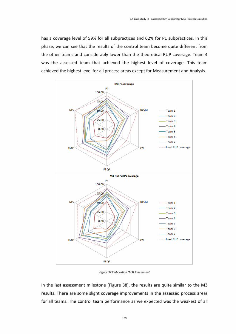
6.4 Case Study III - Assessing RUP Support for ML2 Projects Execution
169
has a coverage level of 59% for all subpractices and 62% for P1 subpractices. In this
phase, we can see that the results of the control team become quite different from
the other teams and considerably lower than the theoretical RUP coverage. Team 4
was the assessed team that achieved the highest level of coverage. This team
achieved the highest level for all process areas except for Measurement and Analysis.
Figure 37 Elaboration (M3) Assessment
In the last assessment milestone (Figure 38), the results are quite similar to the M3
results. There are some slight coverage improvements in the assessed process areas
for all teams. The control team performance as we expected was the weakest of all
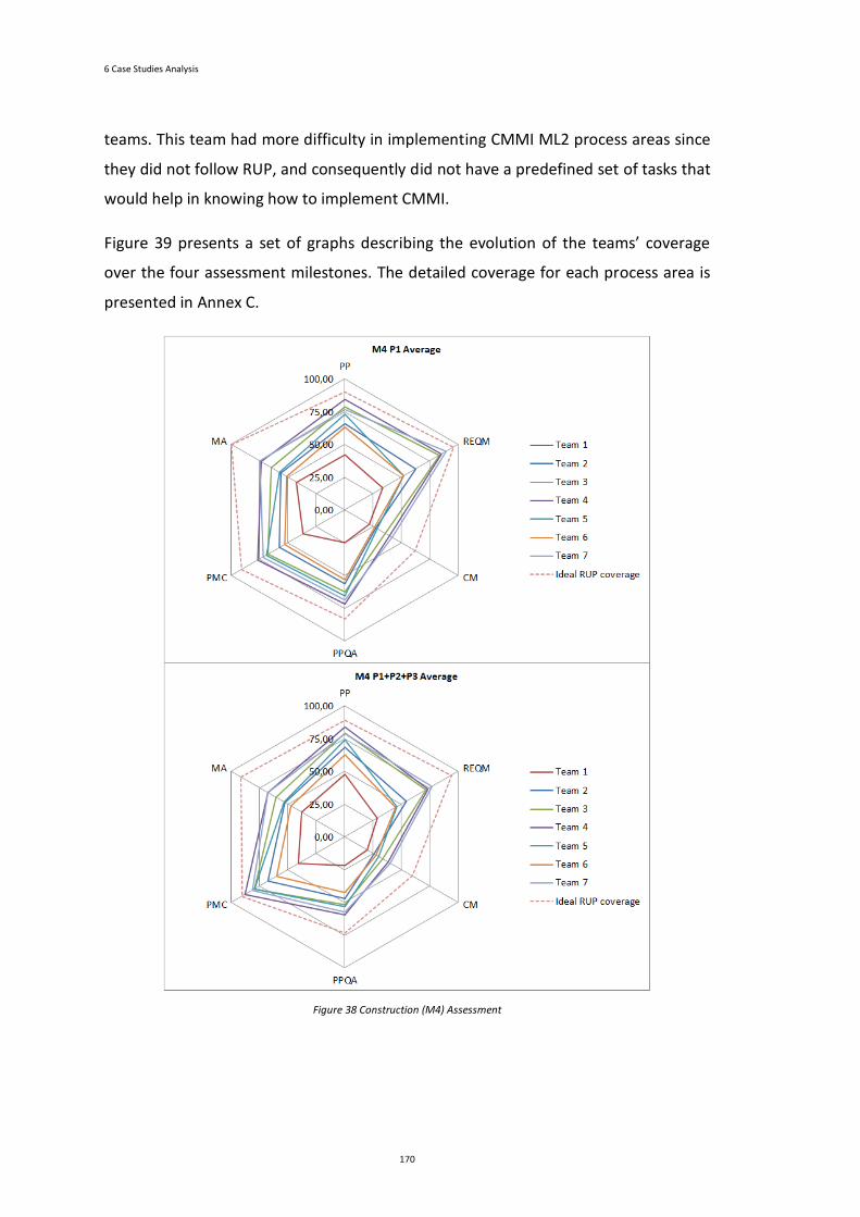
6 Case Studies Analysis
170
teams. This team had more difficulty in implementing CMMI ML2 process areas since
they did not follow RUP, and consequently did not have a predefined set of tasks that
would help in knowing how to implement CMMI.
Figure 39 presents a set of graphs describing the evolution of the teams’ coverage
over the four assessment milestones. The detailed coverage for each process area is
presented in Annex C.
Figure 38 Construction (M4) Assessment
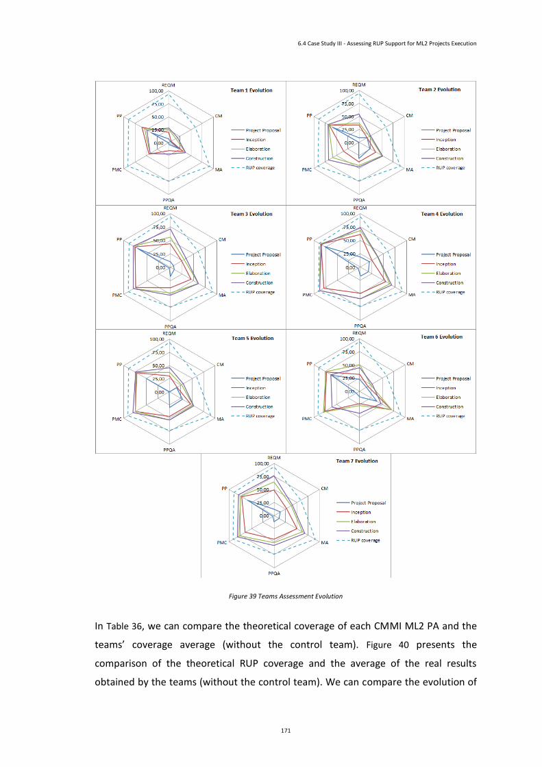
6.4 Case Study III - Assessing RUP Support for ML2 Projects Execution
171
Figure 39 Teams Assessment Evolution
In Table 36, we can compare the theoretical coverage of each CMMI ML2 PA and the
teams’ coverage average (without the control team). Figure 40 presents the
comparison of the theoretical RUP coverage and the average of the real results
obtained by the teams (without the control team). We can compare the evolution of
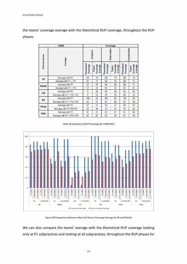
6 Case Studies Analysis
172
the teams’ coverage average with the theoretical RUP coverage, throughout the RUP
phases.
Table 36 Summary of RUP Coverage for CMMI ML2
Figure 40 Comparison between Ideal and Teams Coverage Average by PA and Priority
We can also compare the teams’ average with the theoretical RUP coverage looking
only at P1 subpractices and looking at all subpractices, throughout the RUP phases for

6.4 Case Study III - Assessing RUP Support for ML2 Projects Execution
173
each CMMI ML2 PA. The theoretical RUP coverage achieves the maximum coverage
in the Elaboration phase, but the teams’ average achieves the maximum coverage
only in the Construction phase. The team’s performance reach almost the previously
theoretical estimated coverage, but with some temporal delay; i.e., while the
theoretical pick coverage is possible during the Elaboration phase, the real pick
coverage is observed during the Construction phase for almost all teams.
6.5 Conclusion
The case study analysis presents the results of the several CMMI assessments
performed to evaluate the contributions of this thesis.
In the case study I, we analysed the results of the CMMI ML2 assessment of two types
of teams: teams that have adopted the tailored RUP model (the RUP Reduced Model)
and teams that follow the full RUP model. The results show that, with the adoption of
RUP Reduced Model, the accomplishment of CMMI ML2 was easier and with higher
coverage.
The comparison of the results obtained in the case study II allowed us to conclude
that practitioners adjust their PP effort taking into account the kind of project and
that REQM tasks are generally neglected in the context of elaborating project
proposals.
For case study III, the assessment was based on the adoption of the CMMI-RUP
mapping for the Requirements Management, Project Monitoring and Control, Project
Planning, Measurement and Analysis, Configuration Management and Process and
Product Quality Assurance process areas that have been thoroughly described and
justified in this work. With this case study, we can verify that by adopting RUP the
teams have a higher compliance with CMMI ML2 than the control team that do not
follow RUP, but has also to implement CMMI ML2.

Chapter 7
Conclusion
Chapter Contents
7 Conclusion .....................................................................................................................................177
7.1 Focus of the Work ....................................................................................................................177
7.2 Synthesis of Research Efforts ...................................................................................................178
7.3 Synthesis of Scientific Results ..................................................................................................179
7.4 Future Work ............................................................................................................................180

176
177
7
Conclusion
This chapter presents the conclusion of this work. It contextualizes the work in the
adoption of RUP and CMMI. It then synthesizes the research efforts, the results that
express the contributions of the thesis, and suggests possible research tracks for
future work.
7.1 Focus of the Work
Software quality has become one of the biggest concerns of software development
organizations in recent years. However, developing software with high quality is not
simple. One of the main contributors to the development of high quality software is
the implementation and adoption of software development processes. Capability
Maturity Model Integration and Rational Unified Process are two of the most
well-known software development process frameworks.
Implementing a software development process is a demanding activity for a small
development team. The Capability Maturity Model Integration and Rational Unified
Process frameworks are not suitable for those teams; it requires a high number of
participants and it cannot be easily adopted by them.
This thesis focuses on the tailoring of the CMMI and RUP frameworks aiming to
contribute to an increase of the CMMI compliance by small software development
7 Conclusion
178
teams. These frameworks are composed of a set of guidelines and best practices that
have to be implemented to achieve a quality level compliance. The tailored
frameworks were evaluated with a set of case studies to validate this thesis
contributions.
7.2 Synthesis of Research Efforts
The work performed and described in this document was achieved through the
development of the following major activities stated in the following paragraphs.
In the beginning of the thesis, there was a presentation of an introductory context of
the frameworks involved, the goals, the strategy, contributions, and the structure of
this document. After this introduction, the several efforts carried out were described.
Research on the state-of-art in the area of Capability Maturity Model Integration and
Rational Unified Process was performed. This allowed the characterization of the
Capability Maturity Model Integration and Rational Unified Process frameworks. It
also allowed the characterization of the adoption of Rational Unified Process
framework to achieve Capability Maturity Model Integration compliance. It was
revealed that the existent efforts regarding the adoption of Rational Unified Process
framework to achieve Capability Maturity Model Integration compliance are not
suitable for small software development teams.
A tailored version of the Rational Unified Process framework was adopted both in an
educational environment and in an industrial setting to support its validation. This
RUP Reduced Model defines a small subset of the key participants of the Rational
Unified Process framework and redefines their responsibilities.
In order to identify the constraints that a Capability Maturity Model Integration
process area has from the other process areas, a study was performed to identify the
dependencies between all Capability Maturity Model Integration process areas.
The mapping between the Capability Maturity Model Integration and Rational Unified
Process frameworks was presented. The mapping was focused on the Capability
Maturity Model Integration ML2 and ML3. A detailed mapping of the Capability
7.2 Synthesis of Research Efforts
179
Maturity Model Integration ML2 and the Rational Unified Process framework was
also presented.
To validate the research efforts of the thesis a set of case studies was performed and
analysed. The results of these case studies were presented at the end of the
document.
7.3 Synthesis of Scientific Results
This thesis provides several contributions. Among these contributions are:
• Validated RUP Reduced Model: RUP is quite complex to be implemented
by a small software development team. RUP comprises about 40 roles.
This number of roles is extremely high to be implemented in this type of
team since they do not have enough elements to perform all roles. The
adopted RUP Reduced Model proposes a RUP configuration that comprises
a smaller subset of RUP roles. Only the roles that are essential to the
execution of the software development were kept. The responsibilities of
the other roles (the non-essential roles) were assigned to one of the RUP
Reduced Model roles. The thesis validates the RUP Reduced Model by
assessing this model when compared with the complete RUP framework
through the use of CMMI.
• CMMI Dependencies: Implementing a CMMI process area does not really
mean that only this process area has to be implemented. A process area
usually needs some information that is performed by another process
area. In other words, CMMI process areas have dependencies between
them. The dependencies are not explicitly presented in the CMMI
documentation. A matrix with the dependencies between all the CMMI
Process Areas was defined to overcome this lack of information. The
dependencies are presented by CMMI Maturity Level and by Category.
• CMMI-RUP Mapping: CMMI only defines a set of guidelines that have to
be implemented to achieve a given level of quality. How these guidelines
7 Conclusion
180
will be implemented, is out of the CMMI scope. RUP defines how a
software development project has to be performed to produce a given
product. To help organizations to overcome this gap, a CCMI-RUP mapping
(for CMMI ML2 and ML3) was defined. A detailed mapping for CMMI ML2
was also defined. It indicates how a given CMMI process area can be
implemented through RUP tasks.
During this thesis, some presentations and publications were made. The doctoral
proposal was presented in the Symposium for PhD students in Software Engineering,
SEDES’2009, IEEE CS Press, and the publications made were:
• Paper “Dependency Analysis between CMMI Process Areas”, PROFES’10
Conference, LNCS/Springer-Verlag.
• Paper “Tailoring RUP to Small Software Development Teams”, SEAA’11
Conference, IEEE CS Press.
• Paper “Mapping RUP Roles to Small Software Development Teams”,
SWQD’12 Conference, LNBIP/Springer-Verlag.
• Paper “A Reduced Set of RUP Roles to Small Software Development
Teams”, ICSSP 2012 Conference, IEEE Press.
• Paper “Mapping CMMI and RUP Process Frameworks for the Context of
Elaborating Software Project Proposals”, SWQD’13 Conference,
LNBIP/Springer-Verlag.
A paper has been submitted to the Software Quality Journal (Springer-Verlag), we are
expecting the notification results.
Additionally, it is expected further publications from this dissertation related to the
results and conclusion of the case study analysis.
7.4 Future Work
The work performed along this PhD thesis does not completely cover all the possible
and pertinent research topics relative to the exhaustive analysis of using RUP to
7.4 Future Work
181
support CMMI implementations. Additional research tracks and efforts might be
considered for those that would like to use this PhD document as a baseline for
future work, namely:
• Detail the CMMI-RUP mapping for CMMI ML3.
• Compare the maturity of teams that will adopt the reduced model with
the maturity of other teams that will follow one agile methods approach,
when considering CMMI ML3 specific practices.
• Formalize a roadmap, to achieve CMMI compliance with RUP adoption and
simultaneous usage of the CMMI staged and continuous representation.


183
References
Abrahamsson, P., Salo, O., Ronkainen, J., & Warsta, J. (2002). Agile Software Development Methods: Review and Analysis. Espoo, Finland: Technical Research Centre of Finland.
Abran, A., Bourque, P., Dupuis, R., Moore, J., & Tripp, L. (2004). Guide to the Software Engineering Body of Knowledge - SWEBOK: IEEE Press.
Ahern, D. M., Clouse, A., & Turner, R. (2004). CMMI Distilled: A Practical introduction to Integrated Process Improvement (Second ed.): Addison - Wesley.
Alistair, C. (2004). Crystal clear a human-powered methodology for small teams: Addison-Wesley Professional.
Ambler, S. (2002). Agile Modeling: Effective Practices for Extreme Programming and the Unified Process. New York: John Wiley & Sons, Inc.
Ambler, S. W. (2001). Agile Modeling and the Rational Unified Process (RUP) Retrieved 2011-11-15, 2011, from http://www.agilemodeling.com/essays/agileModelingRUP.htm
Avison, D. E., Lau, F., Myers, M. D., & Nielsen, P. A. (1999). Action research. Commun. ACM, Vol. 42 (1), 94-97.
Barros Paes, C. E., & Hirata, C. M. (2007). RUP Extension for the Development of Secure Systems. 4th International Conference on Information Technology - ITNG 2007, 643-652, [0-7695-2776-0].
Baskerville, R. L. (1999). Investigating information systems with action research. Commun. AIS, Vol. 2 (3es).
Booch, G., Maksimchuk, R., Engle, M., Young, B., Conallen, J., & Houston, K. (2007). Object-oriented analysis and design with applications (3rd ed.): Addison-Wesley.
Borges, P. (2008). Configuração do RUP com Vista à Simplificação dos Elencos Processuais em PMEs de Desenvolvimento de Software. Master Degree Thesis, Universidade do Minho.
References
184
Borges, P., Monteiro, P., & Machado, R. J. (2011). Tailoring RUP to Small Software Development Teams. 37th Euromicro Conference - SEAA 2011, 306-309, IEEE Computer Society Press, [978-0-7695-4488-5].
Borges, P., Monteiro, P., & Machado, R. J. (2012). Mapping RUP Roles to Small Software Development Teams. 4th Software Quality Days Conference - SWQD 2012, 59-70, Springer-Verlag, [978-3-642-27212-7].
Carvallo, J. P., Franch, X., & Quer, C. (2008). Supporting CMMI Level 2 SAM PA with Non-technical Features Catalogues. Software Process: Improvement and Practice, Vol. 13 (2), 171-182.
Cater-Steel, A., Toleman, M., & Rout, T. (2006). Process improvement for small firms: An evaluation of the RAPID assessment-based method. Information and Software Technology, Vol. 48 (5), 323-334.
Chang, G. (2010). Modifying RUP to comply with CMM levels 2 and 3. 2nd International Conference on Information Science and Engineering - ICISE 2010, 1-5, IEEE Computer Society Press, [978-1-4244-7616-9].
Chen, C.-Y., & P. Pete, C. (2011). Software engineering education: A study on conducting collaborative senior project development. Journal of Systems and Software, Vol. 84 (3), 479-491.
Chen, X., Staples, M., & Bannerman, P. (2008). Analysis of Dependencies between Specific Practices in CMMI Maturity Level 2 Software Process Improvement, Communications in Computer and Information Science (Vol. 16, 94-105): Springer-Verlag.
Chrissis, M. B., Konrad, M., & Shrum, S. (2006). CMMI: Guidelines for Process Integration and Product Improvement (2nd ed.): Addison-Wesley.
Cintra, C. C., & Price, R. T. (2006). Experimenting a Requirements Engineering Process Based on Rational Unified Process (RUP) Reaching Capability Maturity Model Integration (CMMI) Maturity Level 3 and Considering the Use of Agile Methods Practices. Workshop em Engenharia de Requisitos - WER 2006, 153-159
CMMI Product Team. (2006). CMMI for Development, Version 1.2 (CMU/SEI-2006-TR-008).
CMMI Product Team. (2010a). CMMI for Acquisition, Version 1.3 (CMU/SEI-2010-TR-032).
CMMI Product Team. (2010b). CMMI for Development, Version 1.3 (CMU/SEI-2010-TR-033).
CMMI Product Team. (2010c). CMMI for Services, Version 1.3 (CMU/SEI-2010-TR-034). .
Coleman, G., & O'Connor, R. (2008). Investigating software process in practice: A grounded theory perspective. Journal of Systems and Software, Vol. 81 (5), 772-784.
Commission, E. (2005). Small and Medium-sized Enterprises Definition Retrieved 2011-02-24, 2011, from http://ec.europa.eu/enterprise/policies/sme/facts-figures-analysis/sme-definition/index_en.htm
Corporation, R. S. (2001). Roadmap: Agile Practices in RUP Retrieved 2011-11-15, 2011
References
185
Dittrich, Y., Rönkkö, K., Eriksson, J., Hansson, C., & Lindeberg, O. (2008). Cooperative method development. Empirical Software Engineering, Vol. 13 (3), 231-260.
Duarte, F. J., Fernandes, J. M., & Machado, R. J. (2006). Business Modeling in Process-Oriented Organizations for RUP-based Software Development Reference Modeling for Business Systems Analysis (98-117): Idea Group Publishing.
Fernandes, J. M., & Duarte, F. J. (2005). A reference framework for process-oriented software development organizations. Software and Systems Modeling, Vol. 4 (1), 94-105.
Gallagher, B., & Brownsword, L. (2001). The Rational Unified Process and the Capability Maturity Model – Integrated Systems/Software Engineering Retrieved 2011-02-10, 2011, from http://www.sei.cmu.edu/library/assets/rup.pdf
Gibson, D. L., Goldenson, D. R., & Kost, K. (2006). Performance Results of CMMI®-Based Process Improvement: Software Engineering Institute, CMU.
Goldenson, D. R., & Gibson, D. L. (2003). Demonstrating the Impact and Benefits of CMMI®: An Update and Preliminary Results: Software Engineering Institute, CMU.
Grundmann, M. (2005). A CMMI Maturity Level 2 assessment of RUP, from http://www.ibm.com/developerworks/rational/library/dec05/grundmann/
Hanssen, G. K., Bjørnson, F. O., & Westerheim, H. (2007). Tailoring and Introduction of the Rational Unified Process. 14th European Conference EuroSPI 2007, 7-18, Springer-Verlag, [978-3-540-74765-9].
Hanssen, G. K., Westerheim, H., & Bjørnson, F. O. (2005a). Tailoring RUP to a Defined Project Type: A Case Study. 6th International Conference on Product Focused Software Process Improvement - PROFES 2005, 209-228, Springer-Verlag, [3-540-26200-8].
Hanssen, G. K., Westerheim, H., & Bjørnson, F. O. (2005b). Using Rational Unified Process in an SME – A Case Study. 12th European Conference EuroSPI 2005, 142-150, Springer-Verlag, [978-3-540-30286-5].
Henderson-Sellers, B., Collins, G., Dué, R., & Graham, I. (2001). A qualitative comparison of two processes for object-oriented software development. Information and Software Technology, Vol. 43 (12), 705-724.
Henderson-Sellers, B., Due, R., Graham, I., & Collins, G. (2000, 2000). Third generation OO processes: a critique of RUP and OPEN from a project management perspective. 7th Asia-Pacific Software Engineering Conference - APSEC 2000, 428-435, IEEE Computer Society, [0-7695-0915-0].
Hesse, W. (2003). Dinosaur meets Archaeopteryx? or: Is there an alternative for Rational’s Unified Process? Software and Systems Modeling, Vol. 2 (4), 240-247.
Hirsch, M. (2002). Making RUP agile. 17th Annual Conference on Object Oriented Programming, Systems, Languages, and Applications - OOPSLA 2002 ACM, [1-58113-471-1].
Humphrey, W. S. (2000). Introduction to the team software process: Addison-Wesley.
References
186
IBM. (2003). Rational Unified Process: Best practices for software development teams Retrieved 29.08.2013, from http://www.ibm.com/developerworks/rational/library/content/03July/1000/1251/1251_bestpractices_TP026B.pdf
IBM. (2006a). RUP for Large Projects, version 7.1
IBM. (2006b). RUP for small projects, version 7.1 Retrieved 12-04-2012, from http://www.wthreex.com/rup/smallprojects/
IBM. (2007). IBM Rational Unified Process with CMMI Compliance Support, Version 7.5.0.1 from http://www.ibm.com/developerworks/rational/downloads/07/rup_cmmi_v1/
International Organization for Standardization. (2000). ISO 9001:2000 - Quality management systems - Requirements. Geneva.
International Organization for Standardization. (2008). ISO 9001:2008 - Quality management systems - Requirements. Geneva.
Iversen, J. H., Mathiassen, L., & Nielsen, P. A. (2004). Managing risk in software process improvement: an action research approach. MIS Quarterly, Vol. 28 (3), 395-433.
Jacobsen, I. (1992). Object Oriented Software Engineering: A Use Case Driven Approach: Addison-Wesley.
Jacobson, I., Booch, G., & Rumbaugh, J. (1999). The unified software development process: Addison-Wesley.
Jieshan, L., & Mingzhi, M. (2009). A Case Study on Tailoring Software Process for Characteristics Based on RUP. International Conference on Computational Intelligence and Software Engineering - CiSE 2009, 1-5, IEEE Computer Society Press, [978-1-4244-4507-3].
Ken, S. (2004). Agile Project Management With Scrum: Microsoft Press.
Kent, B. (2000). Extreme programming explained: embrace change: Addison-Wesley Longman Publishing Co., Inc.
Kruchten, P. (2001). Agility with the RUP. Cutter IT Journal, Vol. 14 (12), 27-33.
Kruchten, P. (2003). The Rational Unified Process: An Introduction (3 ed.): Addison-Wesley.
Kurbel, K. E. (2008). Developing Information Systems The Making of Information Systems (155-234): Springer-Verlag.
Mandjam, F. d. S. (2011). Avaliação do impacto das práticas do CMMI do nível 2, no desempenho de equipas piloto de desenvolvimento de software no ensino. Master Degree Thesis, Universidade do Minho.
Manzoni, L. V., & Price, R. T. (2003). Identifying extensions required by RUP to comply with CMM levels 2 and 3. IEEE Transactions on Software Engineering, Vol. 29 (2), 181-192.
References
187
Marçal, A. S. C., Soares, F. S. F., & Belchior, A. D. (2007). Mapping CMMI Project Management Process Areas to SCRUM Practices. 31st IEEE Software Engineering Workshop - SEW 2007, 13-22, IEEE Computer Society, [0-7695-2862-7].
Marchewka, J. T. (2009). Information technology project management: John Wiley and Sons.
Mejia, J., Muñoz, M., Calvo-Manzano, J. A., Cuevas, G., & San Feliu, T. (2011). A Multi-model Workflow before Establishing an Acquisition Contract Based on CMMI-ACQ Model. 18th European Conference EuroSPI 2011, 1-13, Springer-Verlag, [978-3-642-22206-1].
Monteiro, P., Borges, P., Machado, R. J., & Ribeiro, P. (2012). A Reduced Set of RUP Roles to Small Software Development Teams. 8th International Conference on Software and Systems Process - ICSSP’2012 (within the 34th International Conference on Software Engineering - ICSE'2012), 190-199, IEEE Computer Society, [978-0-7695-4488-5].
Monteiro, P., Machado, R. J., & Kazman, R. (2009). Inception of Software Validation and Verification Practices within CMMI Level 2. 4th International Conference on Software Engineering Advances - ICSEA'2009, SEDES’2009 Workshop, 536-541, IEEE Computer Society, [978-0-7695-3777-15].
Nebiu, B. (2002). Project Proposal Writing Retrieved 2012-05-10, from http://documents.rec.org/publications/ProposalWriting.pdf
Niazi, M., Wilson, D., & Zowghi, D. (2006). Critical success factors for software process improvement implementation: An empirical study. Software Process: Improvement and Practice, Vol. 11 (2), 193-211.
Paulk, M. C. (2001). Extreme programming from a CMM perspective. Software, IEEE, Vol. 18 (6), 19-26.
Paulk, M. C. (2009). A History of the Capability Maturity Model for Software. ASQ Software Quality Professional, Vol. 12, 5-19.
Paulk, M. C., Weber, C. V., Curtis, B., & Chrissis, M. B. (1995). The capability maturity model: guidelines for improving the software process: Addison-Wesley.
Pereira, E. B., Bastos, R. M., & Oliveira, T. C. (2007). A Systematic Approach to Process Tailoring. International Conference on Systems Engineering and Modeling - ICSEM 2007, 71-78, IEEE Computer Society, [1-4244-0771-0].
Procter, R., Rouncefield, M., Poschen, M., Lin, Y., & Voss, A. (2011). Agile Project Management: A Case Study of a Virtual Research Environment Development Project. Computer Supported Cooperative Work, Vol. 20 (3), 197-225.
Project Management Institute. (2008). A Guide to the Project Management Body of Knowledge (PMBOK® Guide) (4th Edition ed.).
Reifer, D. J. (2003). XP and the CMM. Software, IEEE, Vol. 20 (3), 14-15.
Runeson, P., & Höst, M. (2009). Guidelines for conducting and reporting case study research in software engineering. Empirical Software Engineering, Vol. 14 (2), 131-164.
Runeson, P., Höst, M., Rainer, A., & Regnell, B. (2012). Case Study Research in Software Engineering: Guidelines and Examples: John Wiley & Sons, Inc.

References
188
SEI. (2006a). Improving Processes in Small Settings.
SEI. (2006b). Improving Processes in Small Settings, from http://www.sei.cmu.edu/iprc/ipss.html
Siv, F. (1988). Action research on systems development: case study of changing actor roles. ACM SIGCAS Computers and Society, Vol. 18 (1), 22-31.
Smith, J. (2000). Reaching CMM Levels 2 and 3 with the Rational Unified Process Retrieved from http://sce.uhcl.edu/helm/RationalUnifiedProcess/papers/pdf/rupcmm.pdf
SPIRE. Software Process Improvement in Regions of Europe Project Retrieved April 2010, from http://www.cse.dcu.ie/spire/spire.html
Staples, M., & Niazi, M. (2008). Systematic review of organizational motivations for adopting CMM-based SPI. Information and Software Technology, Vol. 50 (7-8), 605-620.
Staples, M., Niazi, M., Jeffery, R., Abrahams, A., Byatt, P., & Murphy, R. (2007). An exploratory study of why organizations do not adopt CMMI. Journal of Systems and Software, Vol. 80 (6), 883-895.
Tatum, M. (2012). What Is a Project Proposal? Retrieved 02-05-2012, from http://www.wisegeek.com/what-is-a-project-proposal.htm
Umeå-University. Quality Management for Small Enterprises Project Retrieved 12-04-2010, from http://www8.cs.umu.se/~jubo/Projects/QMSE/
Uttangi, R. V., & Rizwan, R. Fast track to CMMI implementation: Integrating the CMMI and RUP process frameworks Retrieved 31-01-2012, from http://www.ibm.com/developerworks/rational/library/oct07/uttangi_rizwan/index.html
Villalón, J. A. C.-M., Agustín, G. C., Mejía, J., Gilabert, T. S. F., & Sánchez, A. (2008). CMMI-ACQ: A Formal Implementation Sequences of the Processes Areas at Maturity Level 2. Electronics, Robotics and Automotive Mechanics Conference - CERMA 2008, 212-217, IEEE Computer Society, [978-0-7695-3320-9].
Villiers, M. R. d. (2005). Three approaches as pillars for interpretive information systems research: development research, action research and grounded theory. SAICSIT 2005, 142-151, SAICSIT, [1-59593-258-5].
Wangenheim, C. G. v., Varkoi, T., & Salviano, C. F. (2006). Standard based software process assessments in small companies. Software Process: Improvement and Practice, Vol. 11 (3), 329-335.
Westerheim, H., & Hanssen, G. K. (2005, 30 Aug.-3 Sept. 2005). The introduction and use of a tailored unified process - a case study. 31st EUROMICRO Conference - SEAA 2005, 196-203,
Wilkie, F. G., McFall, D., & McCaffery, F. (2005). An evaluation of CMMI process areas for small- To medium-sized software development organisations. Software Process Improvement and Practice, Vol. 10 (2), 189-201.
189
Annex A:
Case Study I - Assessing RUP
Reduced Model
This annex presents the detailed tables for the CMMI-RUP mapping of Configuration
Management, Process and Product Quality Assurance and the Project and Monitoring
Control process area.
Table 37 presents the detailed mapping of RUP tasks that implements the
Configuration Management process areas.
The detailed mapping of RUP tasks into Process and Product Quality Assurance
subpractices is presented in Table 38.
Finally, the detailed mapping of RUP tasks into the subpractices of the Project and
Monitoring Control process area is presented in Table 39.
The tables are presented below.
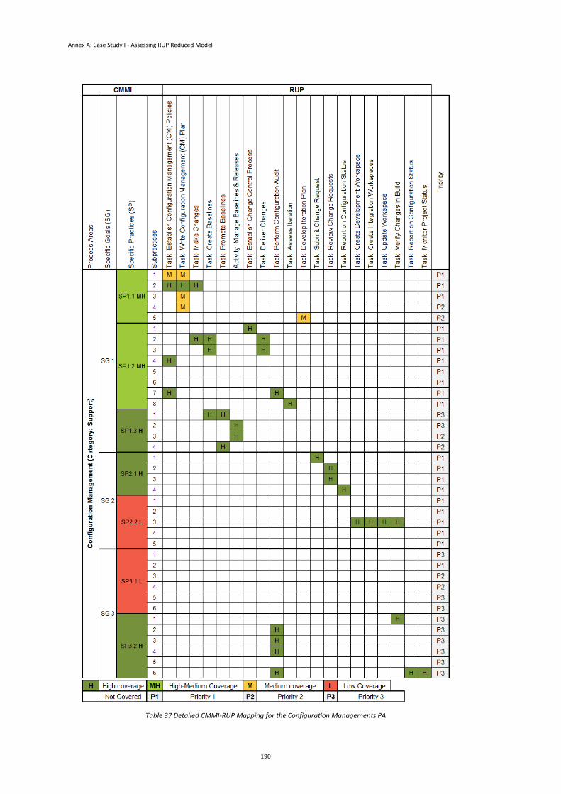
Annex A: Case Study I - Assessing RUP Reduced Model
190
Table 37 Detailed CMMI-RUP Mapping for the Configuration Managements PA
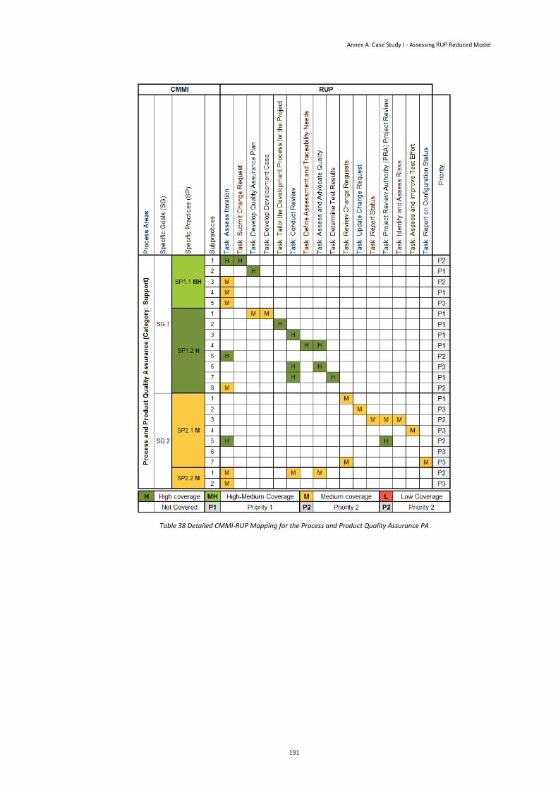
Annex A: Case Study I - Assessing RUP Reduced Model
191
Table 38 Detailed CMMI-RUP Mapping for the Process and Product Quality Assurance PA
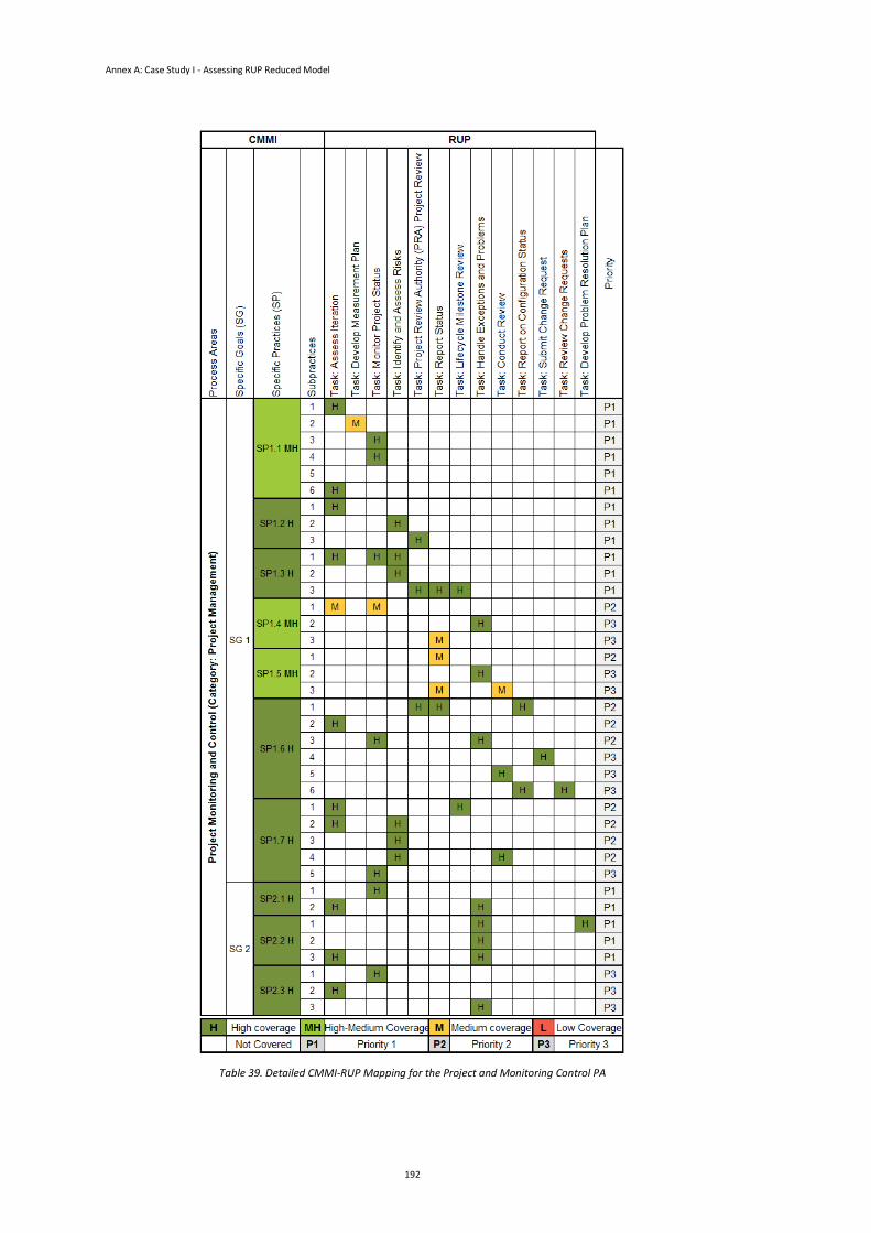
Annex A: Case Study I - Assessing RUP Reduced Model
192
Table 39. Detailed CMMI-RUP Mapping for the Project and Monitoring Control PA
193
Annex B:
Case Study II - Assessing RUP
Support for Project Proposals
This annex presents the detailed coverage for the Measurements and Analysis,
Configuration Management, Process and Product Quality Assurance and the Project
and Monitoring Control process areas.
Table 40 presents the detailed coverage of the CMMI-RUP mapping of Measurement
and Analysis process areas.
Table 41 presents the detailed coverage of the CMMI-RUP mapping of Configuration
Management process areas.
The detailed coverage of the RUP tasks mapping into Process and Product Quality
Assurance subpractices is presented in Table 42.
Finally, the detailed coverage of the RUP tasks mapping into the subpractices of the
Project and Monitoring Control process area is presented in Table 43.
The tables are presented following.
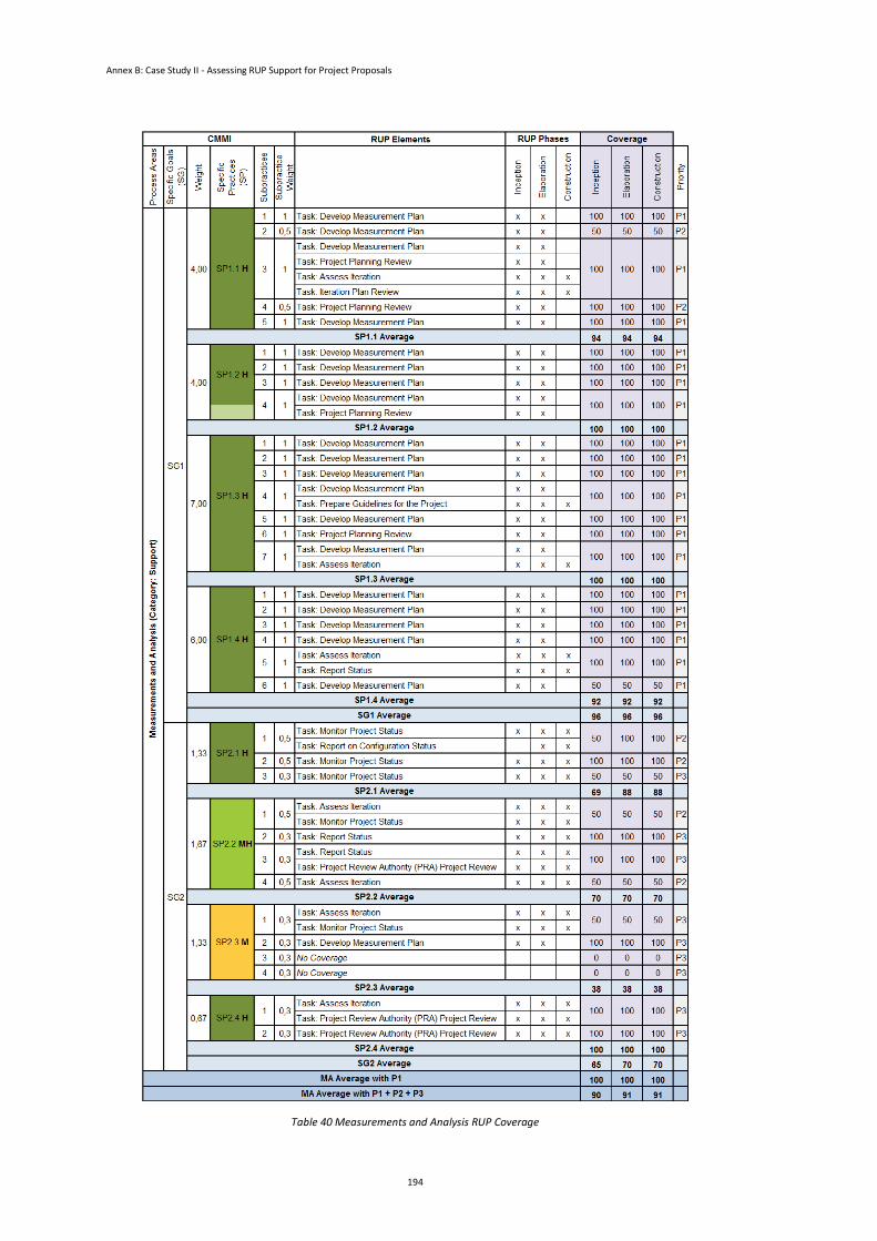
Annex B: Case Study II - Assessing RUP Support for Project Proposals
194
Table 40 Measurements and Analysis RUP Coverage
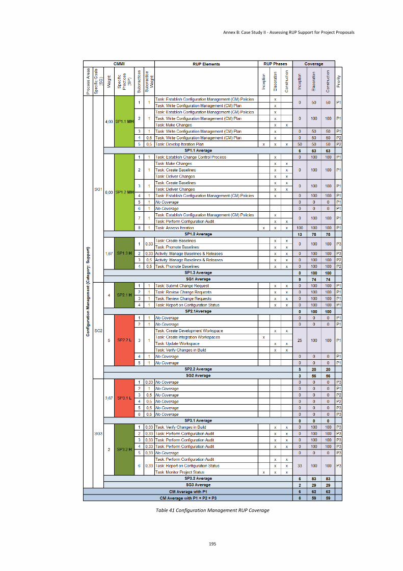
Annex B: Case Study II - Assessing RUP Support for Project Proposals
195
Table 41 Configuration Management RUP Coverage
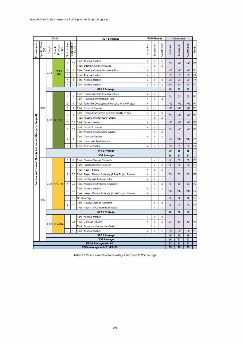
Annex B: Case Study II - Assessing RUP Support for Project Proposals
196
Table 42 Process and Product Quality Assurance RUP Coverage
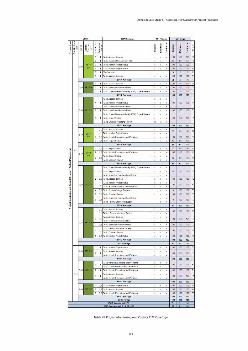
Annex B: Case Study II - Assessing RUP Support for Project Proposals
197
l
Table 43 Project Monitoring and Control RUP Coverage

199
Annex C:
Case Study III - Assessing RUP
Support for ML2 Projects
Execution
This annex presents the detailed results of the Case Study III for the Project Planning,
Requirements Management, Measurements and Analysis, Configuration
Management, Process and Product Quality Assurance and the Project and Monitoring
Control process areas. Each table presents the results of all teams in each process
area. The control team is Team 1.
The detailed results of the Project Planning, Requirements Management,
Measurements and Analysis, Configuration Management, Process and Product
Quality Assurance and the Project and Monitoring Control process areas are
presented in Table 44, Table 45, Table 46, Table 47, Table 48 and Table 49,
respectively.
The tables are presented below.
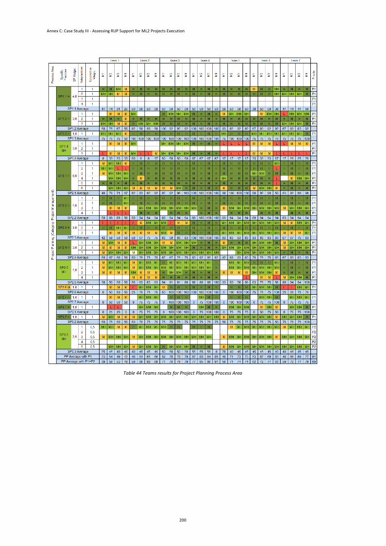
Annex C: Case Study III - Assessing RUP Support for ML2 Projects Execution
200
Table 44 Teams results for Project Planning Process Area

Annex C: Case Study III - Assessing RUP Support for ML2 Projects Execution
201
Table 45 Teams results for Requirements Management Process Area
Table 46 Teams results for Configuration Management Process Area
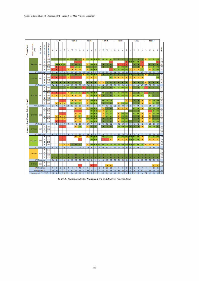
Annex C: Case Study III - Assessing RUP Support for ML2 Projects Execution
202
Table 47 Teams results for Measurement and Analysis Process Area
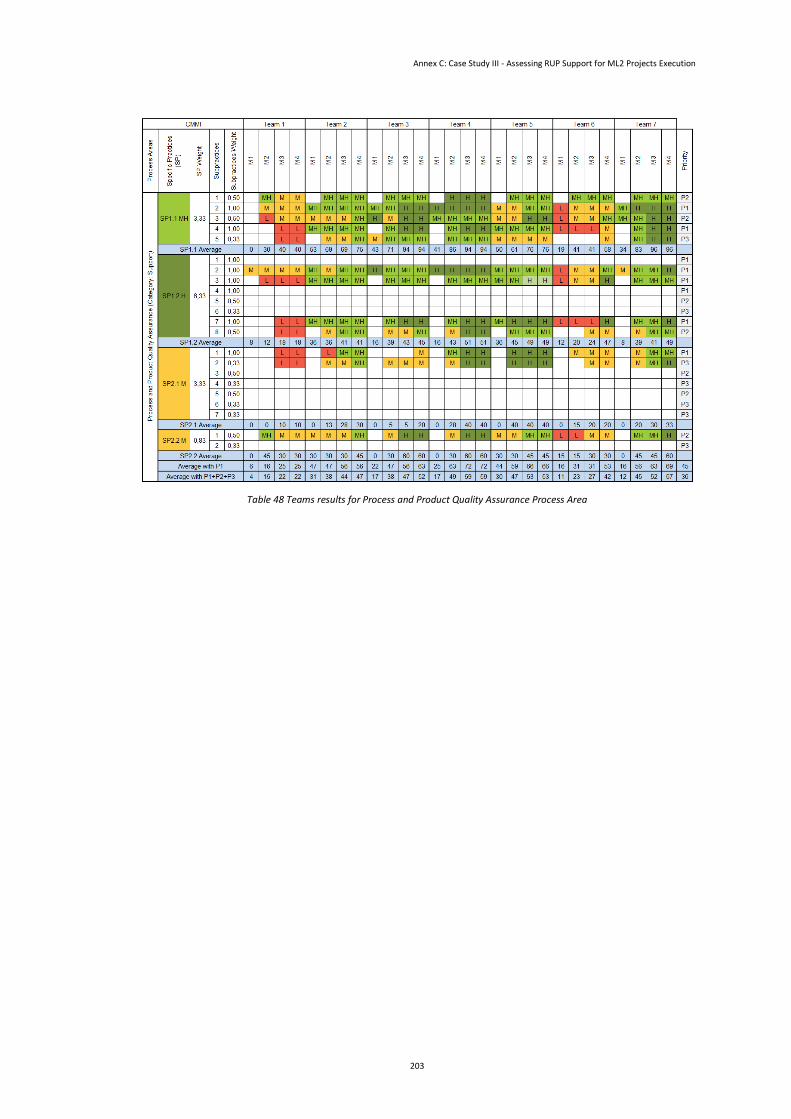
Annex C: Case Study III - Assessing RUP Support for ML2 Projects Execution
203
Table 48 Teams results for Process and Product Quality Assurance Process Area
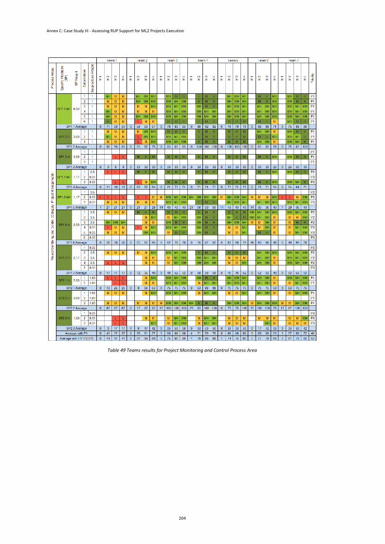
Annex C: Case Study III - Assessing RUP Support for ML2 Projects Execution
204
Table 49 Teams results for Project Monitoring and Control Process Area