Embed Size (px)
Citation preview
1
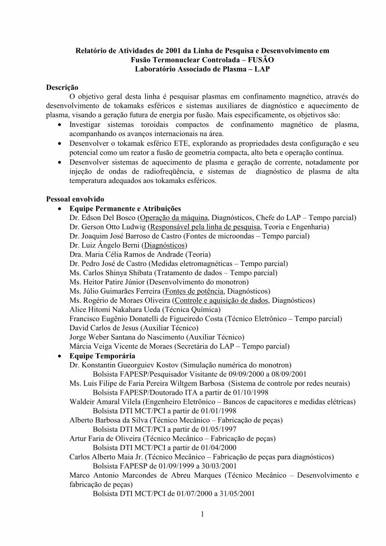
Relatório de Atividades de 2001 da Linha de Pesquisa e Desenvolvimento em Fusão Termonuclear Controlada – FUSÃO
Laboratório Associado de Plasma – LAP Descrição
O objetivo geral desta linha é pesquisar plasmas em confinamento magnético, através do desenvolvimento de tokamaks esféricos e sistemas auxiliares de diagnóstico e aquecimento de plasma, visando a geração futura de energia por fusão. Mais especificamente, os objetivos são:
• Investigar sistemas toroidais compactos de confinamento magnético de plasma, acompanhando os avanços internacionais na área.
• Desenvolver o tokamak esférico ETE, explorando as propriedades desta configuração e seu potencial como um reator a fusão de geometria compacta, alto beta e operação contínua.
• Desenvolver sistemas de aquecimento de plasma e geração de corrente, notadamente por injeção de ondas de radiofreqüência, e sistemas de diagnóstico de plasma de alta temperatura adequados aos tokamaks esféricos.
Pessoal envolvido
• Equipe Permanente e Atribuições Dr. Edson Del Bosco (Operação da máquina, Diagnósticos, Chefe do LAP – Tempo parcial) Dr. Gerson Otto Ludwig (Responsável pela linha de pesquisa, Teoria e Engenharia) Dr. Joaquim José Barroso de Castro (Fontes de microondas – Tempo parcial)
Dr. Luiz Ângelo Berni (Diagnósticos) Dra. Maria Célia Ramos de Andrade (Teoria) Dr. Pedro José de Castro (Medidas eletromagnéticas – Tempo parcial) Ms. Carlos Shinya Shibata (Tratamento de dados – Tempo parcial)
Ms. Heitor Patire Júnior (Desenvolvimento do monotron) Ms. Júlio Guimarães Ferreira (Fontes de potência, Diagnósticos) Ms. Rogério de Moraes Oliveira (Controle e aquisição de dados, Diagnósticos) Alice Hitomi Nakahara Ueda (Técnica Química)
Francisco Eugênio Donatelli de Figueiredo Costa (Técnico Eletrônico – Tempo parcial) David Carlos de Jesus (Auxiliar Técnico)
Jorge Weber Santana do Nascimento (Auxiliar Técnico) Márcia Veiga Vicente de Moraes (Secretária do LAP – Tempo parcial)
• Equipe Temporária Dr. Konstantin Gueorguiev Kostov (Simulação numérica do monotron) Bolsista FAPESP/Pesquisador Visitante de 09/09/2000 a 08/09/2001
Ms. Luis Filipe de Faria Pereira Wiltgem Barbosa (Sistema de controle por redes neurais) Bolsista FAPESP/Doutorado ITA a partir de 01/10/1998
Waldeir Amaral Vilela (Engenheiro Eletrônico – Bancos de capacitores e medidas elétricas) Bolsista DTI MCT/PCI a partir de 01/01/1998 Alberto Barbosa da Silva (Técnico Mecânico – Fabricação de peças) Bolsista DTI MCT/PCI a partir de 01/05/1997 Artur Faria de Oliveira (Técnico Mecânico – Fabricação de peças) Bolsista DTI MCT/PCI a partir de 01/04/2000 Carlos Alberto Maia Jr. (Técnico Mecânico – Fabricação de peças para diagnósticos) Bolsista FAPESP de 01/09/1999 a 30/03/2001
Marco Antonio Marcondes de Abreu Marques (Técnico Mecânico – Desenvolvimento e fabricação de peças) Bolsista DTI MCT/PCI de 01/07/2000 a 31/05/2001
2
Marcos Fiorio Gama Lobo (Técnico Eletrônico – Bancos de capacitores e sistema de vácuo) Bolsista DTI MCT/PCI de 01/05/1997 a 31/05/2001
Néliton Gonçalves de Oliveira (Técnico em Informática – Interfaces dos sistemas de controle e aquisição de dados) Bolsista DTI MCT/PCI de 01/12/2000 a 31/05/2001
Resultados
O desenvolvimento experimental em anos anteriores pode ser resumido da seguinte forma. A fabricação de componentes do ETE foi iniciada em meados de 1995 e quase inteiramente realizada no Laboratório Associado de Plasma do INPE, com recursos financeiros e humanos extremamente limitados. A montagem do ETE começou em junho de 1998 após completada a construção do novo laboratório. Uma precisão melhor que 2 mm foi obtida na montagem conforme especificações detalhadas e restritivas de projeto. Testes da máquina tiveram início em novembro de 1999, envolvendo os sistemas auxiliares de aquecimento da câmara de vácuo e de limpeza por descarga luminescente, enquanto procedia a montagem dos bancos de capacitores. O primeiro plasma de tokamak no ETE foi obtido em 28 de novembro de 2000 com hidrogênio à pressão de 2,4×10⁴ mbar. A corrente de plasma atingiu 11,6 kA e a duração do pulso 1,2 ms.
A campanha de 2001 teve como objetivo melhorar as condições de vácuo e de formação do plasma. Realizou-se um estudo da ruptura de gases injetados no ETE em três condições de pré-ionização: sem pré-ionização, utilizando luz ultravioleta, e utilizando um chuveiro de elétrons produzidos por emissão termoiônica. Os campos magnéticos de êrro, que têm um papel importante durante as fases de ruptura do gás e formação do plasma, foram medidos em várias posições no interior da câmara de vácuo e em diversos instantes durante o acionamento das bobinas de campos toroidal e poloidal. No final de 2001, com apenas 16% do total de capacitores instalado nos bancos, a corrente de plasma no ETE atingiu valores que variaram entre 35 e 45 kA com durações de pulso entre 4,5 e 3 ms, respectivamente.
Um conjunto básico de diagnósticos, compreendendo sinais de controle da máquina, espectroscópicos e magnéticos, encontra-se em condição operacional. O sistema de espalhamento Thomson foi montado e testado. A temperatura de plasma medida nas condições atuais de baixa energia dos bancos de capacitors situa-se na faixa compreendida entre 20 e 50 eV para diferentes condições da descarga. A sonda por feixe rápido de átomos de lítio foi montada, e testes da fonte e do canhão de íons de lítio estão em andamento.
Testes iniciais de um monotron de 6,7 GHz, 30 kW foram realizados. Medidas eletromagnéticas da cavidade fria confirmaram as previsões teóricas tanto para a freqüência e modo de operação da cavidade como para a eficiência de circuito. A primeira versão do canhão eletrônico apresentou problemas de aquecimento excessivo, o que levou à confecção de uma versão melhorada que deverá ser testada em breve.
Foram realizados trabalhos teóricos nas áreas de modelagem do circuito de potência e de transporte zero-dimensional do plasma, de simulação dos efeitos de corrente parasitas, e de cálculos auto-consistentes do equilíbrio de plasma.
Uma descrição completa das atividades realizadas dentro da linha de pesquisa e desenvolvimento em fusão foi feita durante o Joint Meeting of the Second IAEA Technical Committee Meeting on Spherical Tori and the Seventh International Spherical Torus Workshop, organizado pelo LAP e que teve lugar no Instituto Nacional de Pesquisas Espaciais no período entre 1 e 3 de agosto de 2001. Os trabalhos sobre o ETE apresentados durante este evento encontram-se no apêndice. Metas para 2002
Muitas das atividades descritas acima deverão prosseguir durante o ano de 2002. Espera-se que a instalação dos bancos de capacitores seja finalizada visando atingir o patamar de 150 – 200
3
kA da corrente de plasma e 0,3 – 0,4 T do campo magnético toroidal. A operação do ETE será progressivamente otimizada possibilitando estudos do espaço de operação da máquina e de parâmetros do plasma. Testes da sonda por feixe de lítio e medidas iniciais dos parâmetros do plasma na borda do ETE serão realizados. O sistema de aquisição de dados será expandido e o número de sondas magnéticas aumentado de modo a possibilitar estudos iniciais de reconstrução magnética. Um conjunto adicional de limitadores de grafite será instalado na câmara de vácuo e procedimentos de limpeza da câmara terão prosseguimento. Será também iniciado o projeto e construção de partes dos sistemas de interferometria por laser no infravermelho longínquo e de imageamento de raios-X moles. O protótipo do monotron, dispositivo gerador de microondas para pré-ionização e aquecimento do plasma, será montado e testado. Os trabalhos nas áreas de equilíbrio, modelagem zero-dimensional da partida, simulação de fenômenos na borda e transporte neo-clássico do plasma deverão prosseguir durante o ano de 2002. Comentários
O ETE é um dos poucos tokamaks esféricos em operação no mundo, sendo o LAP uma das instituições pioneiras no desenvolvimento deste conceito, a partir de 1986. Atualmente, só existem outras máquinas deste tipo em operação na Inglaterra, nos Estados Unidos, no Japão e na Rússia, e em planejamento na Itália e na China. O LAP mantém contato e colaboração com praticamente todos os grupos internacionais que atuam no desenvolvimento de toróides esféricos, configuração na qual estão concentrados os novos investimentos na área de pesquisa em confinamento magnético, tendo em vista os resultados satisfatórios já atingidos e sem levar em conta os investimentos ainda em discussão que serão empregados na construção do International Thermonuclear Experimental Reactor – Fusion Energy Advanced Tokamak (ITER-FEAT). Esta colaboração entre grupos de pesquisa é em grande parte promovida pela Agência Internacional de Energia Atômica – IAEA, com a qual o LAP mantém um contrato de pesquisa. Acordos específicos de colaboração também são mantidos pelo LAP com o Centro de Ciências de Culham, Inglaterra, com o Instituto Superior Técnico de Lisboa, Portugal, e com a Universidade de Fukui, Japão. Atualmente, as atividades do LAP na área de fusão estão direcionadas para colocação do ETE em condições de operação plena, pela expansão das fontes de potência e pela instalação de sistemas de diagnóstico de plasma e de aquisição de dados, de modo a transformá-lo num experimento de padrão internacional. Deve-se também lembrar que o grupo do LAP encarregado do desenvolvimento de fontes para pré-ionização e aquecimento do plasma é o único no país que mantém competência na área de microondas de alta potência, com reconhecimento internacional. Dificuldades As dificuldades na execução do projeto foram as mesmas encontradas de forma crônica em qualquer atividade de pesquisa, notadamente experimental, no Brasil: 1) indefinição na liberação dos recursos aprovados, geralmente acompanhada de cortes substanciais; 2) empecilhos burocráticos e administrativos que praticamente inviabilizam a pesquisa; 3) falta de continuidade, principalmente no que se refere à transferência de tecnologia para o setor produtivo e de conhecimentos para as futuras gerações; 4) descaso institucional pela área de Ciência e Tecnologia. Particularmente danoso foi o corte de 50% das bolsas MCT/PCI em meados de 2001, que desmantelou a equipe de apoio técnico do laboratório do tokamak ETE. No caso de um projeto como o ETE constata-se, além dos problemas citados, a inexistência de uma política voltada para a questão energética futura do País. O ETE oferece a possibilidade do Brasil acompanhar o desenvolvimento internacional na área de dispositivos compactos de confinamento magnético para fusão. Entretanto, para assegurar este papel, e impedir que o experimento se torne rapidamente obsoleto, é necessário haver um aporte substancial e contínuo de recursos. É também essencial que haja contratação de novos pesquisadores para atuar, principalmente, nas áreas de desenvolvimento de diagnósticos e

4
interpretação de dados experimentais, controle e aquisição de dados, desenvolvimento e utilização de equipamentos para aquecimento de plasma, e desenvolvimento teórico e computacional. Além disso, a atualização e manutenção do experimento depende da contratação de engenheiros eletro-eletrônicos, bem como técnicos experientes em mecânica, eletrônica e de laboratório, em caráter mais permanente que o regime de bolsas. Publicações – Participação em Congressos • Artigos Publicados em Periódicos BARROSO, J.J.; KOSTOV, K.G.; LEITE NETO, J.P. “An axial monotron with rippled wall resonator”. International Journal of Infrared and Millimeter Waves, 22 (2), 265-276, February 2001. BARROSO, J.J. “A triple-beam 6.7 GHz, 340 kW monotron”. IEEE Transaction on Electron Devices, 48 (4) 815-817, April 2001. BARROSO, J.J.; TERRA, M.O.; MACAU, E.E.N. “Bifurcation and chaos in the second instability window of the classical Pierce diode”. International Journal of Bifurcation and Chaos, 11 (10) 251-260 (2001). MONTEIRO, M.J.R.; MACHIDA, M.; DALTRINI, A.M.; BERNI, L.A. “Comparison of two multipass configurations for scattered light amplification”. Brazilian Journal of Physics, 31(3) 502-506, September 2001. • Artigos Aceitos para Publicação em Periódicos BARROSO, J.J.; KOSTOV, K.G. “Triple-beam monotron”. Accepted for publication in IEEE Transactions on Plasma Science. KOSTOV, K.G.; BARROSO, J.J. “Space-charge-limited current in cylindrical diodes with finite-length emitter”. Accepted for publication in Physics of Plasmas. OLIVEIRA, R.M.; UEDA, M.; VILELA, W.A. “Fast neutral lithium beam for density and its fluctuation measurements at the boundary regions of ETE tokamak”. Accepted for publication in Brazilian Journal of Physics, 2001. • Artigos Submetidos para Publicação em Periódicos BARROSO, J.J.; LEITE NETO, J.P.; KOSTOV, K.G. “Cylindrical waveguide with axially rippled wall”. Submitted to IEEE Transactions Microwave Theory and Techniques. CASTRO, P.J.; BARROSO, J.J.; CORRÊA, R.A. “Measurement of electric field azimuthal distribution on gyrotron resonator”. Submitted to International Journal of Electronics. MONTEIRO, M.J.R.; MACHIDA, M.; DALTRINI, A.M.; BERNI, L.A. “Multichannel photomultiplier for multipass Thomson scattering diagnostics”. Submitted to Brazilian Journal of Physics, Proceedings of the 14th IAEA Technical Committee Meeting on Research Using Small Devices, June 25-27, 2001, São Paulo, Brazil. OLIVEIRA, R.M.; BARBOSA, L.F.W., FERREIRA, J.G.; SHIBATA, C.S. “Conceptual project and present status of the ETE control and data acquisiton systems”. Submitted to Fusion Engineering & Design. • Publicações em Congressos Internacionais ANDRADE, M.C.R.; LUDWIG, G.O.; CAMARGO, S.J. “Current density components provided by a self-consistent equilibrium calculation in tokamak plasmas”. Proceedings of the 10th International Congress on Plasma Physics – ICPP, Quebec City, Canada, vol. II, pp. 620, January, 2001. LUDWIG, G.O. “Approximate solutions of the Grad-Schlüter-Shafranov equation”. Fusion Energy 2000, 18th Conference Proceedings, paper THP2/16, p. 418 (5 pages), International Atomic Energy Agency, Vienna, May 2001. BARBOSA, L.F.W.; FERREIRA, J.G.; LUDWIG, G.O.; DEL BOSCO, E.; ROSSI, J.O. “Pulsed electric system for production and confinement of plasma in ETE – Spherical Tokamak

5
Experiment”. Proceedings of the International Conference on Pulsed Power & Plasma Science, June 17-22, 2001, Las Vegas, USA. BARROSO, J.J.; KOSTOV, K.G. “The axial monotron as a high-power microwave tube”. Proceedings do International Conference on Pulsed Power & Plasma Science, June 17-22, 2001, Las Vegas, USA. BARROSO, J.J.; LEITE NETO, J.P.; KOSTOV. K.G. “An axial monotron with rippled wall resonator”. Proceedings do International Conference on Pulsed Power & Plasma Science, June 17-22, 2001, Las Vegas, USA. BARROSO, J.J.; CASTRO, P.J.; ROSSI, J.O.; PATIRE JR., H.; KOSTOV, K.G.; LUDWIG, G.O.; GONÇALVES, J.A.; SANDONATO, G.M.; LEITE NETO, J.P. “High-power microwave research at the Associated Plasma Laboratory of INPE for application in spherical tokamaks”. 14th IAEA Technical Committee Meeting on Research Using Small Devices, June 25-27, 2001, São Paulo, Brazil. DEL BOSCO, E.; LUDWIG, G.O.; FERREIRA, J.G.; BERNI, L.A.; OLIVEIRA, R.M. SHIBATA, C.S.; PATIRE, H.; ROSSI, J.O.; VILELA, W.A.; BARBOSA, L.F.W. “ETE spherical tokamak – design and first results”. 14th IAEA Technical Committee Meeting on Research Using Small Devices, June 25-27, 2001, São Paulo, Brazil. KOSTOV, K.G.; BARROSO, J.J. “Space-charge-limited current in cylindrical diodes with finite-length emitter”. 14th IAEA Technical Committee Meeting on Research Using Small Devices, June 25-27, 2001, São Paulo, Brazil. LEITE NETO, J.P.; BARROSO, J.J.; KOSTOV, K.G. “Electrodynamical properties of axially corrugated waveguides”. 14th IAEA Technical Committee Meeting on Research Using Small Devices, June 25-27, 2001, São Paulo, Brazil. OLIVEIRA, R.M.; UEDA, M.; VILELA, W.A. “Fast neutral lithium beam for density and its fluctuation measurements at the boundary regions of ETE tokamak”. 14th IAEA Technical Committee Meeting on Research Using Small Devices, June 25-27, 2001, São Paulo, SP, Brazil. OLIVEIRA, R.M.; BARBOSA, L.F.W., FERREIRA, J.G.; SHIBATA, C.S. “Conceptual project and present status of the ETE control and data acquisiton systems”. 3rd International Atomic Energy Agency Technical Committee Meeting on Control, Data Acquisition & Remote Participation for Fusion Research, July 13-21, 2001, Padova, Italy. CASTRO, P.J.; BARROSO, J.J.; LEITE NETO, J.P. “Resonance frequencies of cavities with sinusoidally rippled cross sections”. 2001 International Microwave and Optoelectronics Conference, August 6-10, 2001, Proceedings SBMO-IEEE, Belém, PA, 2001, p. 75-78. ANDRADE, M.C.R.; LUDWIG, G.O. “Comparison of bootstrap current models in a self-consistent equilibrium calculation for tokamak plasmas”. Joint Meeting of the 2nd IAEA Technical Committee Meeting on Spherical Tori and the 7th International Spherical Torus Workshop, 1-3 August, 2001, INPE, São José dos Campos, SP, Brazil. BARROSO, J.J.; CASTRO, P.J.; ROSSI, J.O.; PATIRE JR., H.; KOSTOV, K.G.; LUDWIG, G.O.; GONÇALVES, J.A.; SANDONATO, G.M.; LEITE NETO, J.P. “Development of a high-power monotron for RF applications in spherical tokamaks”. Joint Meeting of the 2nd IAEA Technical Committee Meeting on Spherical Tori and the 7th International Spherical Torus Workshop, 1-3 August, 2001, INPE, São José dos Campos, SP, Brazil. BERNI, L.A.; MACHIDA, M.; DEL BOSCO, E.; MONTEIRO, M.J.R.; OLIVEIRA, R.M.; VILELA, W.A.; UEDA, M.; CIOBAN, D.; DALTRINI, A.M.; CASTRO, R.M.; FERREIRA, J.G.; LUDWIG, G.O. “Present status of ETE diagnostics”. Joint Meeting of the 2nd IAEA Technical Committee Meeting on Spherical Tori and the 7th International Spherical Torus Workshop, 1-3 August, 2001, INPE, São José dos Campos, SP, Brazil. DEL BOSCO, E.; FERREIRA, J.G.; BERNI, L.A.; OLIVEIRA, R.M.; LUDWIG, G.O.; SHIBATA, C.S.; PATIRE JR., H.; ROSSI, J.O.; VILELA, W.A.; BARBOSA, L.F.P. W. “Overview of the ETE spherical tokamak”. Joint Meeting of the 2nd IAEA Technical Committee Meeting on Spherical Tori

6
and the 7th International Spherical Torus Workshop, 1-3 August, 2001, INPE, São José dos Campos, SP, Brazil. GRISHANOV, N.I.; AZEVEDO, C.A.; LUDWIG, G.O.; NETO, P.J. “Radio frequency wave dissipation by electron Landau damping in elongated spherical tokamaks”. Joint Meeting of the 2nd IAEA Technical Committee Meeting on Spherical Tori and the 7th International Spherical Torus Workshop, 1-3 August, 2001, INPE, São José dos Campos, SP, Brazil. NAKAMURA, K.; IGUCHI, H.; UEDA, M. et al. “Two dimensional measurement using lithium beam probe at the helical divertor region in CHS(I)”. Annual Meeting of Plasma and Nuclear Fusion, November 27-30, 2001, Fukuoka, Japan. • Resumos em Congressos Internacionais BARBOSA, L.F.P.W.; OLIVEIRA, R.M.; SHIBATA, C.S.; FERREIRA, J.G. “ETE control and data acquisiton system”. 14th IAEA Technical Committee Meeting on Research Using Small Fusion Devices, USP, p. 45, São Paulo, June 25-27, 2001. • Resumos em Congressos Nacionais BERNI, L.A.; DEL BOSCO, E.; LOBO, M.F.G. “First results of wall conditioning on the ETE spherical tokamak”. XXII Congresso Brasileiro de Aplicações de Vácuo na Indústria e na Ciência – XXII CBRAVIC, p. 44, 25-27 de julho de 2001, UNESP, Campus de Guaratinguetá, Guaratinguetá, SP. MONTEIRO, M.J.R.; MACHIDA, M.; DALTRINI, A.M.; CIOLAN, D.; BERNI, L.A. “Use of a 10 stage 64 channel photomultiplier tube for low-light scattering diagnostics”. XXII Congresso Brasileiro de Aplicações de Vácuo na Indústria e na Ciência – XXII CBRAVIC, p. 56, 25-27 de julho de 2001, UNESP, Campus de Guaratinguetá, Guaratinguetá, SP. OLIVEIRA, R.M.; UEDA, M. “Investigation of Li+ thermionic sources for fast neutral lithium beam probing”. XXII Congresso Brasileiro de Aplicações de Vácuo na Indústria e na Ciência – XXII CBRAVIC, p. 57, 25-27 de julho de 1002, UNESP, Campus de Guaratinguetá, Guaratinguetá, SP. DEL BOSCO, E.; FERREIRA, J.G.; BERNI, L.A. “Plasma formation in the ETE spherical tokamak”. XXII Congresso Brasileiro de Aplicações de Vácuo na Indústria e na Ciência – XXII CBRAVIC, p. 59, 25-27 de julho de 2001, UNESP, Campus de Guaratinguetá, Guaratinguetá, SP. BARROSO, J.J.; CASTRO, P.J.; ROSSI, J.O.; PATIRE JR., H.; KOSTOV, K.G.; LUDWIG, G.O.; GONÇALVES, J.A.; SANDONATO, G.M.; LEITE NETO, J.P. “Monotron development for application in spherical tokamaks”. XXII Congresso Brasileiro de Aplicações de Vácuo na Indústria e na Ciência – XXII CBRAVIC, p. 60, 25-27 de julho de 2001, UNESP, Campus de Guaratinguetá, Guaratinguetá, SP. LEITE NETO, J.P.; BARROSO, J.J.; CASTRO, J.P. “Eigenmodes and ohmic losses in cylindrical cavity resonators with sinusoidally rippled cross sections”. 6o Encontro Brasileiro de Física dos Plasmas, p. 26, 1-5 dezembro, 2001, Campos do Jordão, SP. PATIRE, H. JR., BARROSO, J.J.; CASTRO, P.J.; ROSSI, J.O.; LUDWIG, G.O.; GONÇALVES, J.A.; SANDONATO, G.M. “Design and construction of a 20A, 10kV injection electron gun”. 6o Encontro Brasileiro de Física dos Plasmas, p. 26, 1-5 dezembro, 2001, Campos do Jordão, SP. CASTRO, P.J.; BARROSO, J.J.; LEITE NETO, J.P. “Azimuthally corrugated cavities for harmonic gyrotron”. 6o Encontro Brasileiro de Física dos Plasmas, p. 32, 1-5 dezembro, 2001, Campos do Jordão, SP. LUDWIG, G.O.; DEL BOSCO, E.; FERREIRA, J.G.; BARROSO, J.J.; BERNI, L.A.; OLIVEIRA, R.M. “First results of the ETE Spherical Torus”. 6o Encontro Brasileiro de Física dos Plasmas, p. 53, 1-5 dezembro, 2001, Campos do Jordão, SP. ANDRADE, M.C.R.; LUDWIG, G.O. “Different bootstrap current and plasma conductivity models applied in a self-consistent equilibrium calculation for tokamak plasmas”. 6o Encontro Brasileiro de Física dos Plasmas, p. 55, 1-5 dezembro, 2001, Campos do Jordão, SP.

7
BERNI, L.A.; UEDA, M.; DEL BOSCO, E. “Present status of the Thomson scattering diagnostic for Tokamak ETE”. 6o Encontro Brasileiro de Física dos Plasmas, p. 59, 1-5 dezembro, 2001, Campos do Jordão, SP. BARBOSA, L.F.W.; LUDWIG, G.O. “Aplicação e testes de redes neurais artificiais em sistema de levitação magnética para futura aplicação no controle vertical de plasma em tokamaks". 6o Encontro Brasileiro de Física dos Plasmas, p. 59, 1-5 dezembro, 2001, Campos do Jordão, SP. OLIVEIRA, R.M.; UEDA, M.; BERNI, L.A. “Development of a fast neutral lithium beam diagnostic to probe the edge plasma of the ETE tokamak”. 6o Encontro Brasileiro de Física dos Plasmas, p. 61, 1-5 dezembro, 2001, Campos do Jordão, SP. • Relatórios Técnicos Internos BARBOSA, L.F.P.W.; LUDWIG, G.O. “Redes neurais no modelamento e controle de tokamaks – aplicação ao ETE (Experimento Tokamak Esférico) – Terceiro Relatório”. INPE-8477-PRP/226, novembro 2001. • Outros Trabalhos CASTRO, P.J. “Monotron e cavidades azimutalmente corrugadas: aplicação à geração de microondas de alta potência”. Projeto individual de Pesquisa submetido e aprovado pela Fundação de Amparo à Pesquisa do Estado de Paulo – FAPESP, processo no 2001/02496-6, março 2001.
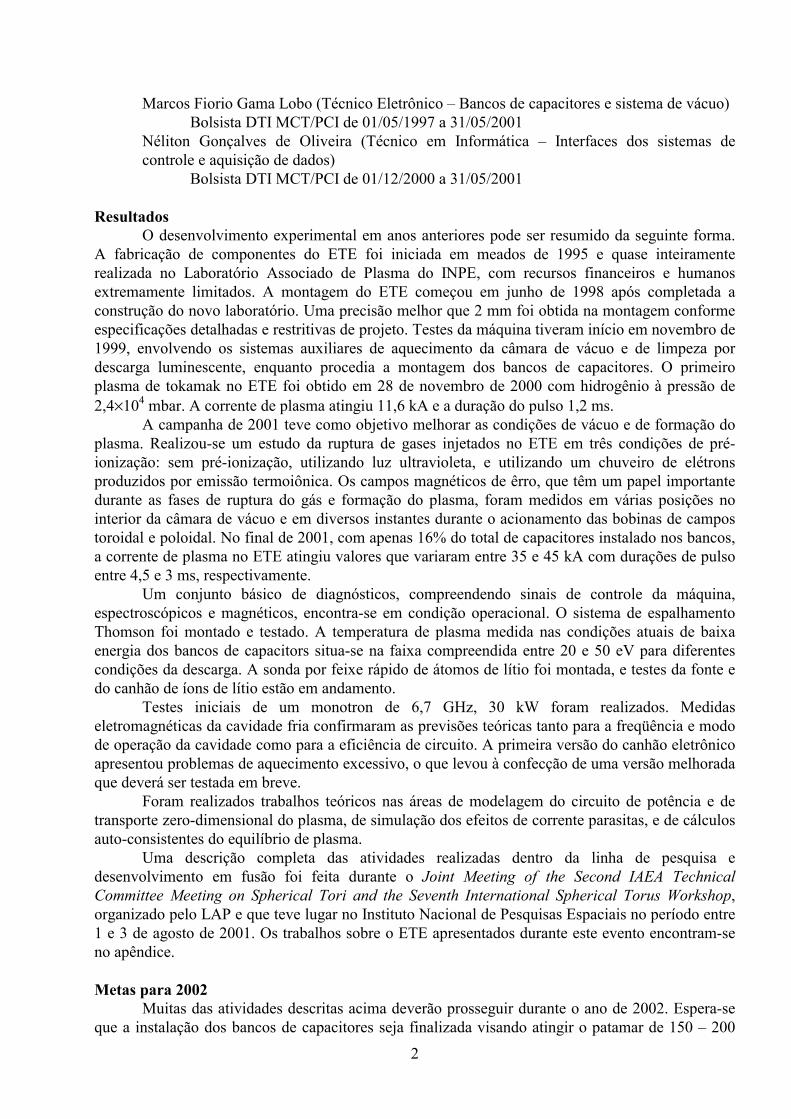
Vista geral do tokamak esférico ETE em Novembro de 2001.
8
Apêndice Trabalhos realizados dentro da linha de pesquisa e desenvolvimento em fusão termonuclear
controlada que foram apresentados durante o Joint Meeting of the Second IAEA Technical Committee Meeting on Spherical Tori and the Seventh International Spherical Torus Workshop, São José dos Campos, SP, 1 a 3 de agosto de 2001:
• ANDRADE, M.C.R.; LUDWIG, G.O. “Comparison of bootstrap current models in a self-consistent equilibrium calculation for tokamak plasmas”.
• BARROSO, J.J.; CASTRO, P.J.; ROSSI, J.O.; PATIRE JR., H.; KOSTOV, K.G.; LUDWIG, G.O.; GONÇALVES, J.A.; SANDONATO, G.M.; LEITE NETO, J.P. “Development of a high-power monotron for RF applications in spherical tokamaks”.
• BERNI, L.A.; MACHIDA, M.; DEL BOSCO, E.; MONTEIRO, M.J.R.; OLIVEIRA, R.M.; VILELA, W.A.; UEDA, M.; CIOBAN, D.; DALTRINI, A.M.; CASTRO, R.M.; FERREIRA, J.G.; LUDWIG, G.O. “Present status of ETE diagnostics”.
• DEL BOSCO, E.; FERREIRA, J.G.; BERNI, L.A.; OLIVEIRA, R.M.; LUDWIG, G.O.; SHIBATA, C.S.; PATIRE JR., H.; ROSSI, J.O.; VILELA, W.A.; BARBOSA, L.F.P. W. “Overview of the ETE spherical tokamak”.
• GRISHANOV, N.I.; AZEVEDO, C.A.; LUDWIG, G.O.; NETO, P.J. “Radio frequency wave dissipation by electron Landau damping in elongated spherical tokamaks”.

Comparison of Bootstrap Current Models in aSelf-Consistent Equilibrium Calculation for Tokamak Plasmas
M. C. R. Andrade* and G. O. Ludwig
Instituto Nacional de Pesquisas Espaciais, POBox 515, 12201-970, São José dos Campos, SP, Brazil*E-mail: [email protected]
1. Introduction. Different bootstrap current formulations are employed in a self-consistentequilibrium for tokamak plasmas where the total plasma current profile is supposed to havecontributions of the diamagnetic, Pfirsch-Schlüter, and the neoclassical ohmic and bootstrapcurrents [1]. A comparison among the different bootstrap current models is performed for avariety of plasma parameters of the small aspect ratio tokamak ETE (Experimento TokamakEsférico) [2], placed at the Associated Plasma Laboratory of INPE, in Brazil. The calculationsdescribed here were performed using the Mathematica package in a PC type computer.
2. Equilibrium and Self-Consistent Calculation. A self-consistent equilibrium calculation,valid for arbitrary aspect ratio tokamaks, is obtained through a direct variational techniquewhere the extremum of the functional given by the internal plasma energy represents the fluxsurface averaged Grad-Shafranov equation (GS) being, in this way, a solution to the plasmaequilibrium. This extremum establishes a relation between the total poloidal current, I(ρ),between the symmetry axis and a given magnetic surface, denoted by the radial coordinate ρ,and the total plasma current enclosed by this surface, IT(ρ), as follows [1]:
ρρρ−
ρρ
ρρ−=
ρρ
d
dp
d
dV)(K
d
dI)(I
d
dL)(K
d
dI)(I T
T , (1)
where p(ρ) is the total plasma pressure profile and L(ρ), V(ρ) and K(ρ) are, respectively, theinductance of the toroidal solenoid coincident with a given flux surface, the volume involvedby this surface and the inverse kernel used to calculate the self-inductance of the plasma loop.The self- consistent calculation requires that the current profile which satisfies Eq. (1), hasalso to be given by the sum of all current components, described by:
d�
dp
B
I�I
B
BJI
B
BJ
)K(
)(I
d�
dII
2
20
2
bs
2
ohT +
⋅+
⋅
ρρ
=−
����
, (2)
where the first term on the rhs of Eq.(2) refers to the ohmic current (oh) modified byneoclassical effects through the plasma conductivity, the second term to the bootstrap current(bs) calculated through different models as described in the next section and the last termresults from a combination of the diamagnetic (dia) and the Pfirsch-Schlüter (ps) currents.The brackets in Eq.(2) refer to the usual flux surface average and B
�
is the total induction inthe plasma. The self-consistent equilibrium is obtained when Eq.(2) is solved iteratively withEq.(1) as described in [1]. The loop voltage that enters in the ohmic current calculation isdetermined consistently in order to reproduce the prescribed value of the total plasma current.
3. Bootstrap Current Models. Different bootstrap current models are listed in Table 1 andclassified according their validity regarding aspect ratio, collisionality or plasma impuritylevel. The full matrix Hirshman-Sigmar (H-S) formulation for the bootstrap current estimateis based on the solution of the system formed by the flux surface average of the parallelmomentum and heat flow balance equations for each species in the plasma, as follows [3]:

µ µ µ µa a a a aa
aa a
abb
ab b
bbu B V B
q
pB V B u B
q
pB1 1 1 2 2 2 11 12
2
5
2
5/ // /
/ // /− + − = −
∑ l l (3)
µ µ µ µa a a a aa
aa a
abb
ab b
bbu B V B
q
pB V B u B
q
pB2 2 1 3 3 2 21 22
2
5
2
5/ // /
/ // /− + − = − +
∑ l l (4)
The solution of this system provides the parallel fluid <ua//B> and heat <2qa///5pa> flows for eachspecies in terms of the thermodynamic flows (described through Va1 and Va2) and determines thebootstrap current through the expression ∑=⋅ a B//auaeanBbsJ , where na and ea are
respectively the density and charge of species a. The Hirshman-Sigmar model is therefore suitablefor a multi-species plasma treatment since the equations in the system above are addedaccordingly as the number of plasma species increases. lij
ab are the friction coefficients, which are
independent of the magnetic field configuration and so, valid in all collision frequency regimes.Their formulae are found in [3]. The problem is then to calculate the viscosity coefficients µaj ,since they depend on the plasma geometry and collisionality. We will make a comparison among
the H-S [3], Shaing [4] and Sauter´s [5] proposals regarding this calculation.In order to compute the viscosity coefficients, the Hirshman-Sigmar model solves the
linearized drift kinetic (ldk) equation asymptotically in each collisionality regime and proposes aformula continuously valid throughout the various regimes. However, in the plateau regime theresult is valid only for large aspect ratios. Shaing solves the ldk equation where the mass velocityappears explicitly. The asymptotic values of his coefficients converge to the same values given bythe Hirshman-Sigmar model in the Pfirsch-Schlüter and in the banana regimes, when the H-Sbanana coefficient is corrected by a 1/fc factor in order to reproduce the correct limit in the finiteaspect ratio banana regime (fc is the fraction of circulating particles in the plasma). In the plateauregime Shaing´s coefficients are different from those derived by Hirshman-Sigmar. Both the H-Sand Shaing´s models consider, however, an approximated Coulomb collision operator which canintroduce errors up to 20% in the viscosity coefficients in the Pfirsch-Schlüter regime [3], whichcould be a problem mainly in trying to model the plasma edge. Finally, Sauter solves ldk´sequations for electrons and a single-ion species without considering plasma flows. In order tosolve these ldk´s equations, Sauter uses an adjoint formalism and does not make any assumptionregarding different collisionality regimes being, in this respect, completely general. Moreover,Sauter considers the full Coulomb collision operator and solves the adjoint equations varyingaspect ratio, collisionality and ion charge Z. In this way, he proposes fitted formulae for thebootstrap current and for the neoclassical conductivity, whose expressions depend basically onthese three parameters. For more accurate formulas regarding the ion charge dependence, Sautershould solve the adjoint equations for electrons and for each ion species as it is stressed in hispaper. Multi-species effects are therefore approximately treated in his formulation by substitutingthe ion charge Z by the effective ion charge in the plasma (Zeff). All the equations describing thesemodels are found respectively in [3,4,5].
Models Aspect Ratio Collisionality ImpuritiesHinton-Hazeltine large all Single-ion (Zeff)
Hirshman all banana regime Single-ion (Zeff)Hirshman-Sigmar large all Multi-Species
Shaing all all Multi-SpeciesSauter all all Single-ion (Zeff)
Table 1: Different formulations for the bootstrap current estimate
4. Results and Discussions. Bootstrap current estimates provided by the full matrix Hirshman-Sigmar model with the viscosity coefficients given by Shaing (H-S/Shaing model) and by thefitted formulae proposed by Sauter, both for the bootstrap current and for the neoclassical

conductivity, are presented for the ETE low aspect ratio tokamak [2]. For Shaing´s model, wecompute the neoclassical conductivity according to the Hirshman, Hawryluk and Birge(HHB) formulation [6]. In both cases, the trapped particle fraction is estimated according toLin-Liu and Miller [7]. The main ETE parameters correspond to aspect ratio A=R0(a)/a=1.5,major radius R0(a)=0.3 m, plasma current Ip=200 kA, vacuum toroidal field BT=0.4 T (atR0(a)=0.3 m), and plasma beta during the ohmic phase β=4-10%. The pressure, electron andion temperature profiles were taken as gaussian shaped functions as in f(ρ) = f(0) exp[-αf (ρ/(wf-ρ))2], where f(0) determines the profile value at the axis, whereas αf and wf
determine the value at the boundary. We have also considered Te(0) = Ti(0),Te(a) = Ti(a) = 0.03 keV and αTe = αTi = 0.2. As the pressure profile is given as a fixed inputin our code, the density profiles were derived from the fact that the total pressure in theplasma is p = neTe + ∑k kTkn and from the quasi-neutrality condition ( ∑= k kke Znn ), with
the summations taken over all ion species. In Table 2, results provided by the self-consistentcalculation for hydrogen plasmas in the ETE tokamak, lead to bootstrap current fractionsroughly ranging from 10 to 35% for both models analysed according to the optimization levelof the plasma parameters. We can also observe, by comparing cases II and V, that plasmaswith higher shaped factors (higher elongation κ(a) in our case) generate higher fractions ofbootstrap current and that the presence of 2% of carbon in the plasma (Zeff=1.54) causes aslight decrease in the bootstrap current fraction as noticed from cases II and III. Sauterpredicts slightly higher fractions of bootstrap current in relation to the H-S/Shaing model inall cases analysed. The highest difference between the two models occurs for case IV (morecollisional with (Te(0) = 200 eV)). This may be due a combined effect resulting from the factthat Sauter uses the complete Coulomb collision operator whereas Shaing uses theapproximated one, and that Shaing´s viscosity coefficients are derived from a different drift-kinetic equation which may result in differences in relation to Sauter´s, mainly in thetransition banana-plateau or plateau-Pfirsch-Schlüter regimes.
p(0) (kPa) Te,i(0) (keV) ααααp κκκκ(a) ΙΙΙΙΤΤΤΤ(a)(kA) Zeff ββββI ββββ0 IbsShaing/IT(a) IbsFIT/IT(a)
I 15 0.5 3.0 2.0 200 1.54 0.54 0.09 0.36 0.37
II 10 0.4 3.0 2.0 200 1.00 0.36 0.06 0.23 0.25
III 10 0.4 3.0 2.0 200 1.54 0.36 0.06 0.22 0.24
IV 10 0.2 3.0 2.0 200 1.00 0.36 0.06 0.14 0.20
V 10 0.4 3.0 1.7 200 1.00 0.31 0.06 0.17 0.19
VI 10 0.4 3.0 1.7 180 1.54 0.38 0.06 0.22 0.23Table 2: Plasma parameters for bootstrap current estimate provided by the self-consistent calculation
Figure 1 shows the total equilibrium current density profiles and all their differentcomponents for case II in Table 2, both for the bootstrap current obtained from theH-S/Shaing model (1a) and from the fitted formula proposed by Sauter (1b). For theH-S/Shaing model the neoclassical conductivity used in the ohmic current calculation isobtained from the HHB formulation [6] whereas in (1b) we have used Sauter´s fitted fomula[5]. Figure 2 shows the comparison of the bootstrap current profiles obtained from differentmodels for cases II, III and IV. We can observe that, as the plasma becomes less collisional(higher temperatures in the cases shown) all the models approach each other. For figures 2aand 2b, the Hirshman collisionless model [8] always predicts more bootstrap current since itdoes not take properly into account the collisionality dependence on the viscosity coefficients.Still comparing figures 2a and 2b we see that as the Zeff increases the H-S/Shaing and Sauter´smodels approach each other. The strongest difference between the two predictions (fig. 2c)occurs for the most collisional case (Te(0) = 200 eV) as previously mentioned. For the lesscollisional plasma (fig.2d) all the models agree quite well. The self-consistent calculation

generated when the bootstrap current is determined by the fitted formulae is approximatelyfour times faster to compute than that provided when the H-S/Shaing model is used. Finally,figure 3 shows the neoclassical and Spitzer conductivities calculated for the HHB formulationand from the fitted formula, for case II, after the self-consistent calculation is achieved andobtained for the bootstrap current calculated according to Sauter. The figure also shows thereduction of the neoclassical conductivity in relation to Spitzer´s.
Figure 1: Current density profiles for case II in Table 2.The full line corresponds to the total equilibrium currentdensity, the dashed line is the ohmic contribution, the dash-dotted line is the sum of the diamagnetic and Pfirsch-Schlüter components and the dotted line represents the boostrap current contribution.
Figure 2: Bootstrap current profiles obtained from different models
Figure 3: Neoclassical and Spitzer conductivities
References[1] Andrade M.C.R., Ludwig G. O. and Camargo S.J.,Plasma. Phys. and Control. Fusion 42, 1269 (2000).[2] Del Bosco E. et al, Overview of the ETE SphericalTokamak in this workshop.[3] Hirshman S.P, Sigmar, D. J., Nuclear Fusion 21,1079 (1981).[4] Shaing K. C. et al, Phys.Plasmas 3, 965 (1996).[5] Sauter O. et al, Phys. Plasmas 6, 2834 (1999).[6] Hirshman S. P. et al, Nuclear Fusion 17, 611 (1977).[7] Lin-Liu Y. R. and Miller R. L., Phys. Plasmas 2,1666 (1995).[8] Hirshman, S.P., Phys. Fluids 31, 3150 (1988).
Development of a High-Power Monotron for RF Applications in Spherical Tokamaks
J. J. Barroso, K. G. Kostov, P. J. Castro, J. O. Rossi, H. Patire, Jr., G. O. Ludwig,
J. A. Gonçalves, G. M. Sandonato, and J. P. Leite Neto
Associated Plasma Laboratory, INPE, P.O. Box 515, São José dos Campos, SP, Brazil
Abstract: Electron cyclotron heating (ECH) assist has been demonstrated to significantly
improve startup performance of tokamaks by decreasing the loop voltage, which translates into ramp current rates higher than those of pure Ohmic startup at equivalent loop voltages. This has been observed on several machines that normally rely on the use of gyrotrons or an assembly of klystrons to produce such beneficial effects at particular electron cyclotron resonance frequencies. However, specific RF source requirements in terms of frequency and power demand specially customized designs, leading to costly industrial tubes. In light of these considerations, pre-ionization and plasma production on the ETE spherical tokamak of LAP/INPE are currently being pursued on the basis of the monotron, which, consisting of an electron beam that traverses a standing-wave cavity resonator, ranks as the simplest microwave tube. Thus describing the design, construction techniques and simulation results of a high-power microwave tube, the present paper reports on a proof-of-principle monotron experiment currently under way at our laboratory.
1. Introduction
Having been known since the 1930s [1,2], the monotron is a transit-time oscillator where the beam electrons cross the interaction space in a transit angle close to (4k+1)π/2 where k is an integer. Under this synchronism condition, the beam can interact unstably with a cavity mode, causing the RF field to grow at the expense of the DC beam energy [3,4]. Electron bunches are formed in the beam and reach the cavity end plate in a decelerating phase of the RF field thus transferring energy to the cavity RF field. The bunches constitute a fluctuating component of the convection current that induces in the resonator walls an RF current to sustain the oscillations. The present paper addresses the monotron by examining its capabilities regarding high efficiency operation with three hollow concentric beams to produce hundreds of kilowatt power output. 2. High-Efficiency Operating Regime
The analysis developed in this section is a one-dimensional Lagrangian treatment in which a representative number of electrons injected at the input plane is traced through the cavity taking account of the presence of a standing-wave electric field. Neglecting the space-charge forces between the charged particles in the beam, the normalized force equation is written as
)~
/~cos()~cos(~~~
20 dzlt
mcd
A
td
pd πϕε +
= (1)
with
222 ~)(~
~~
pcm
ctp
td
zd
+= (2)
where mctpp /)(~ = is the normalized electron momentum, with the time normalized as
Ttt /2~ π= and the distance as czz /~ ω= , q= -e and m are the electronic charge and the
electron rest mass, ϕ specifies the electron entrance phase, l is an integer number defining the field distribution along the normalized interaction length cdd /
~ ω= ; 00 qV=ε denotes the
initial energy of the injected beam, where V0 is beam voltage; A=V/V0 is defined as the field amplitude parameter where V=E/d is the maximum RF voltage established across the cavity.
Given an axial number l and specifying the initial electron momentum, we infer that the final momentum of a single electron upon reaching the collector plate at z=d on a transit time τ(ϕ) is determined by the entrance phase ϕ and by the set of parameters d
~, A, and 0ε .
The corresponding final kinetic energy for a single electron is ( )1)/)((1)( 22 −+= mcpmcs ττε (3)
and the kinetic energy of the exit beam at z=d is calculated by averaging out the individual electron energies over the phase ϕ
)(1
)(2
1 2
0 1, d
Nd
N
ksksB ∫ ∑
=
==π
εϕτεπ
ε (4)
where N is the total number of electrons injected during a period T. The electronic efficiency is expressed by 0/1 εεη Bel −= . On account of (1) the efficiency is seen to be a function of
the normalized quantities A, d~ , and 0ε , i.e. ),
~,( 0εηη dAelel = for a given index l specifying
the electric field axial profile. If elη thus calculated is positive, then the electrons transfer
energy to the RF field. In what follows, the electronic efficiency is maximized and given as a function of the single parameter d
~ . The input beam energy 0ε and the axial number l are
fixed and (1) is numerically integrated using the optimum value of the amplitude parameter A such that a maximum efficiency is calculated from (4) with N=500.
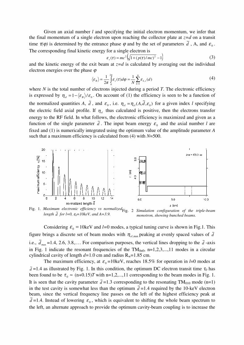
Fig. 1. Maximum electronic efficiency vs normalized
length d~
for l=0, ε0=10keV, and A=3.9.
Fig. 2 Simulation configuration of the triple-beam
monotron, showing bunched beams.
Considering =0ε 10keV and l=0 modes, a typical tuning curve is shown in Fig.1. This
figure brings a discrete set of beam modes with max,elη peaking at evenly spaced values of d~
i.e., max
~d =1.4, 2.6, 3.8,.… For comparison purposes, the vertical lines dropping to the d
~ -axis
in Fig. 1 indicate the resonant frequencies of the TM0n0, n=1,2,3,...,11 modes in a circular cylindrical cavity of length d=1.0 cm and radius Rw=1.85 cm.
The maximum efficiency, at 0ε =10keV, reaches 18.5% for operation in l=0 modes at
d~ =1.4 as illustrated by Fig. 1. In this condition, the optimum DC electron transit time τ0 has been found to be ≈0τ (n+0.15)T with n=1,2,...,11 corresponding to the beam modes in Fig. 1.
It is seen that the cavity parameter d~ =1.3 corresponding to the resonating TM010 mode (n=1)
in the test cavity is somewhat less than the optimum d~ =1.4 required by the 10-keV electron
beam, since the vertical frequency line passes on the left of the highest efficiency peak at d~ =1.4. Instead of lowering 0ε , which is equivalent to shifting the whole beam spectrum to
the left, an alternate approach to provide the optimum cavity-beam coupling is to increase the

cavity d~ from 1.3 to 1.4. Noting that cdd /
~ ω= and that the cavity radius Rw is determined from the boundary condition, )(/)/15()( 0 GHzfcmR nW χπ= one gets ddR nW
~/0χ= where n0χ
denotes the n-th zero of the Bessel function J0. Keeping constant the interaction length d=1.0 cm, and considering operation in the TM010 mode ( 01χ =2.4048), the cavity radius has to be
decreased from 1.85 cm to 1.72 cm for optimum operation. Selecting, however, the higher order TM040 mode 04χ =11.7915 the required cavity radius is calculated as Rw=8.42cm.
3. Triple-Beam Monotron This Section describes the nominal geometry of a monotron having three annular beams at the maxima of the radial distribution of the electric field in a TM040-mode cavity with a circular aperture through which electromagnetic energy stored in the resonant cavity is extracted to the output guide. At an injection beam energy keV100 =ε , the optimum cavity
dimensions of the monotron considered here have been determined in the previous section as length d=1.0cm and radius Rw=8.42cm, which gives a resonant frequency
))(/)(/15( 04 cmRpf wπ= =6.68GHz, and normalized length 4.1~ =d . By viewing the cavity as a
short-circuited diode, the beams are injected from the left and run in the temperature-limited regime with each current in proportion to the area of the beams' cross-section, i.e., II = Jc/π[r2,i
2-r1,i2] where Jc is the current density. The beams are 0.4-cm thick and centered at the
positions r=2.8, 5.1, and 7.4 cm, which correspond to three consecutive maxima of the radial electric field distribution for the TM04 mode in an empty circular cavity. As depicted in Fig. 2, the resonant cavity is aperture coupled by means of a circular iris that transmits the RF power generated in the cavity to the 2.0-cm-radius output guide in which the lowest order TM01 mode propagates down. In the waveguide, a resistive disk is inserted having a resistance per unit square equal to the characteristic wave impedance of the TM01 output wave to absorb completely the incident wave[4]. 4. PIC Code Simulation Results By considering two values of RI namely 0.8 cm and 0.9 cm in the monotron configuration of Fig. 2, the results given in this section encompass the overall efficiency η and average output power Pout over a total current range. The output power and total efficiency have been calculated from particle-in-cell (PIC) simulations. The program used is the KARAT code [5], that is based on 21/2-D axisymmetric PIC model in which the Maxwell's equations and the equation of motion for macroparticles are solved self-consistently. The physical system is run on a grid with square cells 1 mm size with over three thousand macroparticles representing each beam in the configuration space as shown in Fig. 2 during steady state when the electron beams become fully density-modulated.
Fig. 3. Dependence of output power and overall
efficiency on total current for RI=0.8 cm.
Fig. 4. Dependence of output power and overall
efficiency on total current for RI= 0.9 cm.

For RI=0.8 cm, the dependence of both Pout and η on total current is presented in Fig. 3. About the output power, it is seen in Fig. 3 that Pout closely follows a linear increase with current before saturating at 320 kW for current levels above 230 A; the corresponding efficiency curve features a flat region of 14.5% efficiencies. Similar plots of Pout and η for RI=0.9 cm are given in Fig. 4. In this case, while saturating at 670 kW for currents in excess of 525 A, the output power reaches the optimal value of 560 kW at 14.8% efficiency and 378 A current.
For the higher power case discussed above, the total time history of output power at z=5.0 cm is shown in Fig. 5. On steady state the constant-amplitude signal corresponds to the average power level of 560 kW. It is to be noted that the waveform amplitude is always positive, meaning that the output signal is a positive traveling wave. The frequency spectrum of the steady state electric field at the point z=5.0cm, r=1.0cm in the output guide is shown in Fig. 6, with a sharp spectrum centered at 6.67GHz, very close to the cold cavity eigenfrequency of 6.68 GHz.
Fig. 5. Total time history of RF output power at
section z=5.0cm of the output guide.
Fig. 6. Frequency spectrum of electric field at r=1.0cm,
z =5.0cm.
5. Conclusions A triple-beam TM040 monotron oscillator has been presented for which a 21/2-D particle-in-cell simulation has indicated output powers in excess of 500 kW at 6.7GHz. The system includes a simple structure where the elementary functions of electron bunching and energy transfer to the RF field are performed in a single circular cylindrical cavity, which makes the monotron a compact, lightweight device. The cavity geometry (radius 8.42 cm, length 1.0 cm) and operating beam energy (10 keV) have been determined on the basis of a one-dimensional analysis, upon neglecting space-charge forces, that predicts a conversion efficiency of about 15.5%. The system has mechanical simplicity, and circular symmetry, for easy machining and assembly as well as a solid anode block for improved cooling and thermal management in long pulse operation. Such characteristics make the device practical from the viewpoint of cost and flexibility, allowing simple procedures for scaling power and frequency.
References [1] C. K. Birdsall, and W. B. Bridges, Electron Dynamics of Diode Regions, New York: Academic Press, 1966, sec. 1.06. [2] J. J. Müller and E. Rostas, “Un generateur a temps de transit utilisant un seul resonateur de volume”, Helvet. Phys. Acta, vol. 13, pp. 435-450, Oct. 1940. [3] J. J. Barroso, and K. G. Kostov “A 5.7GHz, 100 kW microwave source based on the monotron concept”, IEEE Trans. Plasma Science, vol. 27, pp. 580-586, April 1999. [4] J. J. Barroso, “Design facts in the axial monotron“, IEEE Trans. Plasma Science, vol. 28, pp. 652-656, June 2000. [5] V. P. Tarakanov, “User's Manual for Code KARAT”, Berkeley Research Associates., Inc., Springfield, USA, 1994.

Present Status of ETE Diagnostics
L. A. Berni, M. Machida1, M.J.R Monteiro1, R. M. Oliveira , E. Del Bosco ,W. A. Vilela, M. Ueda, D. Cioban1, A.M. Daltrini1, R.M. Castro, J. G. Ferreira ,G. O. Ludwig
Instituto Nacional de Pesquisas Espaciais, Laboratório Associado de Plasma (INPE/LAP) São José dos Campos, SP, Brasil, CEP 12201-970
1 Universidade Estadual de Campinas, Instituto de Física "Gleb Wataghin" (UNICAMP/IFGW) Campinas, SP, Brasil, CEP 13083-970
1. Introduction
The spherical tokamak ETE (Experimento Tokamak Esférico) [1] has started its operation at LAP/INPE. The ETE is a small aspect ratio tokamak (R/a = 1.5), with major radius R = 0.3 m and minor radius a = 0.2 m. In the first phase of operation the following macroscopic plasma parameters are expected: toroidal induction field of 0.4 T, ohmic current up to 220 kA, plasma pulse duration of 15 ms, density of about 5×10¹⁹ m-3 and temperature around 300 eV. A set of fundamental diagnostics is now being implemented comprising electromagnetic, Thomson scattering, mass spectrometer, fast visible spectroscopy and CCD camera. Other diagnostics as fast neutral lithium beam probe, CO2 interferometer and soft X-ray tomographer are being developed. 2. Available diagnostics Some of the electromagnetic diagnostics are already installed, including three Rogowski coils to measure the currents in the toroidal, vertical and ohmic circuits; one Rogowski coil placed inside the chamber for plasma current measurements and one outside the vessel to measure the induced current; twelve loop voltage coils (six around the vessel, five around the ohmic heating solenoid and one inside the chamber), and four magnetic probes inside the vessel to measure the vertical and radial fields. Figure 1 shows the signals of an initial ETE shot, with 11 kA in the toroidal magnetic coils, 4 kA in the ohmic coils and 2 kA in the equilibrium coils. The ETE vacuum vessel manufactured with Inconel has no electrical break in the toroidal direction. For the shot presented in figure 1, the induced current in the vessel reached 60 kA. For this shot a plasma current of about 8 kA was obtained with loop voltage of 15 V.
A high speed CCD camera with 1/500 to 1/20,000 frame speed and 30 to 500 FPS (upgradeable to 10,000 FPS) is being used. Since in the present condition the duration of the discharge is limited to 1.5 ms, just one frame per shot can be obtained. Figure 2 shows the upper part of the plasma cross-section taken with the CCD camera. The expected D-shaped cross section is clearly observed. A monochromator (1200 lines/mm, 12 Å/mm) coupled with a photomultiplier tube has been installed for ion temperature measurements by Doppler broadening. The Há behavior is being measured by a fixed slit (22 Å) monochromator with a photomultiplier tube. A photodiode is being used to measure the continuous emission (300 nm to 1100 nm). A mass spectrometer connected to the port of the vacuum system is used for measurements during vacuum chamber conditioning. 3. Diagnostics being installed
A 10J ruby laser Thomson scattering system (TS) [2] is being assembled (figure 3) to measure the plasma density and temperature profiles. A special collection lens allows to measure up to 22 spatial plasma points (with 15 mm spatial resolution) along the laser line and a five channel polychromator (that detects temperatures from 20 eV to 2 keV and densities greater than 1019 m-3) will be used to measure the scattered light. A 1.3 m flight tube and a dump with special black anodized inserts were designed to prevent stray light effects.

A 10 keV Fast Neutral Lithium Beam probe (FNLB) [3] with current density up to 1 mA/cm2 and life time of 400 min is being assembled for measurements of the boundary plasma density and its fluctuations. This plasma diagnostic method is adequate for use in fusion devices because it does not perturb the plasma and it provides data with high space and time resolution for the entire discharge lifetime. Figure 4 shows the schematic of the FNLB for the ETE tokamak. The ion beam is extracted from a heated (~ 1153oC) glassy â-eucryptite [4] source and a set of three electrostatic lenses is used to extract, accelerate and collimate the beam that is neutralized by sodium vapor before entering the tokamak chamber. A flight tube with differential pumping prevents the plasma contamination. The lithium line profile will be measured at 90o using a multichannel detection system composed of a spectrometer and photomultipliers, allowing simultaneous multipoint measurements. 4. Planned Diagnostics
One chord CO2 (10.6µm) Michelson heterodyne interferometer modulated at 40 MHz has been designed to measure the line density. A HeNe laser (633 nm or 3.39 ìm) will be used to eliminate the effect of mechanical vibrations. The viability of a multipass interferometer to increase the wavelength shift is under consideration. Figure 5 shows this possibility, where two spherical mirrors can be set outside the vacuum vessel to reflect the CO2 beam several times (22 passes in this case) before it leaves the plasma.
The application of a 64-channel photomultiplier for multipoint Thomson scattering is now under development [5]. Each channel of the detector has a 2.54mm × 2.54mm sensitive area, 5.0 ns response time, 10 stage dynodes with gain of 1x10⁶ at 1150 V, 270nm to 800nm spectral response, and 14% cross talk (measured) between channels. The detector is mounted on a SPEX spectrometer (11 Å/mm, f = 1 m) that allows temperature measurements up to 500 eV. Rayleigh and spectral calibration was performed in the plasma laboratory at UNICAMP. Figure 6 shows the multichannel detector intensity calibration. 5. Conclusion
Since ETE started operation in November 2000 the main efforts are concentrated on conditioning the vacuum vessel to achieve better plasma discharges and to install the basic diagnostics. The TS system should be operational in a two months period and nitrogen Rayleigh scattering will be used for density calibration. The FNLB should start probing the plasma by the middle of 2002. The design of the interferometer system (INPE/UNICAMP) is ready and it should be operational in two years from now. Multichannel detectors for the TS upgrade are being developed jointly with the UNICAMP plasma group. 6. References [1] E. Del Bosco, et al.; Proc. IAEA Technical Committee Meeting on Spherical Tori, 26-28
October, 1998, Tokyo, p 239 [2] M. Bassan, et al.; Rev. Sci. Instrum. 68 (1), 718 (1997) [3] R.M. Oliveira, W.A Vilela, M. Ueda; Proc. 14th IAEA on Research Using Small Fusion
Devices, 25-27 Jun., 2001, SP, Brazil [4] M. Ueda, R.R. Silva, R.M Oliveira, et al; J. Phys. D: Appl. Phys. 30 (1997), 2711-2716 [5] L. Erikson et al.; IEEE Trans. Nucl. Sci., 34, 344 (1987) Acknowledgements. The authors thank FAPESP, FINEP and CNPq for financial support. Thanks also to Dr. Odim Mendes Jr. for loaning the CCD camera (FAPESP 1998/3860-9).

0 1 2 3 4
05
1015
Loop voltage
TIME (ms)
VL
(V)
0 1 2 3 4
0
4
8Plasma current
I P (
kA)
0.000000000 1.000000047 2.000000095 3.000000142 4.000000190
03060 Vessel current
I V (
kA)
0.000000000 1.000000047 2.000000095 3.000000142 4.000000190
0
1
2
Equilibrium coil currentI E (
kA)
0 1 2 3 4
024
Shot ETE-1274
Ohmic heating coil currentI O (
kA)
0 1 2 3 48
10
12
Toroidal coil currentI T (
kA)
Figure 2. D-shaped plasma picture taken with the CCD camera
Figure 1. Rogowski and loop voltage signals
Figure 3. Thomson scattering system for the ETE tokamak
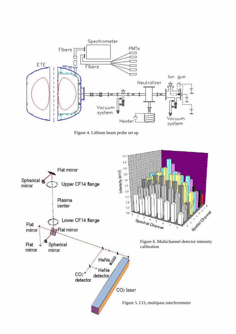
Figure 4. Lithium beam probe set up
Figure 5. CO2 multipass interferometer
Figure 6. Multichannel detector intensity calibration
Overview of the ETE Spherical Tokamak Experiment
E. Del Bosco, J.G. Ferreira, L.A. Berni, R.M. Oliveira, G.O. Ludwig, C.S. Shibata, H. Patire Jr., J.O. Rossi, W.A. Vilela, L.F.W. Barbosa
Instituto Nacional de Pesquisas Espaciais – INPE
Laboratório Associado de Plasma – LAP São José dos Campos – CEP 12.227-010 – SP– Brazil
This paper gives an overview of the ETE spherical tokamak activities in course at
LAP/INPE, emphasizing the measurements of stray fields in the plasma region, produced mainly by eddy currents in the vacuum vessel, as well as measurements of gas breakdown and first plasma formation.
Introduction The ETE spherical tokamak is a small size machine with some innovative
technological features making possible a compact design with good access for plasma diagnosis. The main objectives of ETE are the investigation of operating regimes and confinement properties with emphasis on the plasma edge physics, as well as diagnostics development in fusion-related plasmas with low aspect ratio configuration.
The construction of ETE was initiated in 1995 and the first tokamak plasma was obtained by 28 November 2000. Presently, the experiments are focused on plasma formation, wall conditioning and diagnostics implementation. ETE was designed to reach inductive toroidal plasma current up to 400kA for about 100ms of time duration and confined by an external toroidal magnetic field of less than 0.8T. With the present low energy configuration of the capacitor banks (toroidal field – TF: 128kJ, ohmic heating – OH: 160kJ/single swing and equilibrium field – EF: 76kJ), plasma current of the order of 30kA was expected with duration up to 5ms. These values were practically achieved, with a maximum plasma current of 34kA lasting 2.6ms and a typical current of 21kA lasting 3.3ms.
Stray magnetic fields play an important role during the gas breakdown and plasma formation. Measurements of these fields without plasma are presented. It is shown that even with a relatively high eddy current in the vacuum vessel a null in the magnetic field configuration is formed, allowing the plasma formation. Plasma equilibrium is already achieved as confirmed by a CCD picture of the plasma cross-section. Optimization of the operating parameters, wall conditioning and increase of the capacitor banks energy is under way in order to reach the design values.
Apparatus
The assembly of the machine was completed successfully with an overall precision of about 2mm according to a very strict design. The central stack (l = 1.87m, d = 168.8mm), which is composed by the 12 internal TF coil legs and by a two layers (130 turn each) solenoid was the most challenging piece completely manufactured in our laboratory. Table 1 gives the main parameters of the coils after assembling and the maximum currents actually obtained.
Baking of the vacuum vessel is presently limited to about 75o C due to the lack of a thermal isolation blanket. During glow discharge cleaning a variable butterfly-like valve placed in front of the turbo-drag pump controls the gas flow. Viton O’rings are still fitted in a few ports. The minimum base pressure already achieved is about 10-7 mbar. A stainless steel frame (with electric insulation breaks) is placed inside the vessel in one toroidal location, holding bars of high purity graphite used as limiters. This frame also protects the Rogowski

coil and a few magnetic pick-up coils. A total flux coil is also placed inside the vacuum vessel to measure the loop voltage at R = 0.443m.
Figure 1 presents the temporal current profiles of the three main coil circuits as well as the current induced in the vacuum vessel. The coil currents shown are the maximum obtained in the present configuration of the capacitor banks. The current rise in the TF coil is obtained by firing a fast bank (0.9kV) and the flat top (10ms) is maintained by firing three slow banks (90V each). The toroidal field at R = 0.3m is about 0.0078T/kA. The current waveform in the equilibrium coil is pre-programmed using one fast bank (2kV) and two slow banks (200V each). The maximum vertical field is about 35mT obtained when eddy currents in the vessel have already decayed. The current rise in the OH coil is produced by discharging a fast bank (4kV), which breaks down the gas insulation, and the plasma current is maintained by firing one slow bank (2kV). The maximum induced voltage at R0 due to the OH coil is about 7.2V. This value can reach about 10V when the equilibrium field is also present.
Coil R
(mm) Z
(mm) Turns
I (kA)
Solenoid 72.7 0 2×130 ∼ 4 Compensation
1 102 ± 657 2×10 ∼ 4
Compensation 2
651 ± 883 1×2 ∼ 4
Elongation 200 ± 830 4×4 - Equilibrium 700 ± 422 4×4 ∼ 2
Toroidal - - 12
D-shaped in series
∼ 11 -4 0 4 8
0
2
4
6
8
10
12
0
20
40
60
80
100
120
VE
SS
EL
CU
RR
EN
T (
kA)
Vessel
Equilibrium coil
Ohmic coil
Toroidal coil
CO
IL C
UR
RE
NT
(kA
)
TIME (ms)
Table 1. Parameters of the coils Figure 1. Waveforms of the currents in the coils and current
induced in the vacuum vessel
Stray fields Stray fields in the plasma region can be generated by several means: bad
compensation of the solenoid, misalignment of poloidal coils, bending of TF coils, and induced currents. These fields are undesirable during plasma formation since they can prevent gas breakdown. Because the vacuum vessel of ETE has no electrical break in the toroidal direction relatively high values are expected for the current induced on its walls, notwithstanding the high electrical resistive Inconel alloy used in its manufacture. This current is in opposite direction relative to the currents in the coils, reaching its peak at the very beginning of the poloidal field bank discharges. Preliminary measurements of these stray fields were carried out and are presented in the following.
Figure 2 shows the radial profiles of the vertical magnetic field (Bz) due to the equilibrium (open squares), ohmic heating (open circles) and toroidal (open triangles) circuits as well as the total Bz produced by firing all banks together (solid squares and line). The fields were measured approximately at 0.2ms after triggering the OH bank, which corresponds roughly to the instant of breakdown. The values of the coil and vessel currents in that instant of time are also shown in the picture. It can be observed from figure 2 that the total Bz profile crosses the zero-axis at R ∼ 0.45m. It is noteworthy to point out that the vertical equilibrium field (open squares) is not a stray field; on the contrary, its trigger time is experimentally adjusted in order to compensate for the stray fields creating the null point. Figure 3 shows the radial profile of the radial magnetic field, Br, generated by the ohmic heating (solid circles) and equilibrium (open squares) circuits for the same conditions of figure 2.

0.0 0.2 0.4 0.6 0.8
-8
-4
0
4
(IV=61.9kA)
E: 0.9kA OH: 2.2kAT: 9.5kA Total
VE
RT
ICA
L F
IELD
(m
T)
RADIUS (m)
0.0 0.2 0.4 0.6 0.8
-0.8
-0.6
-0.4
-0.2
0.0
Equilibrium
Ohmic heating
RA
DIA
L F
IELD
(m
T)
RADIUS (m)
Figure 2. Bz radial profile due to ohmic heating, equilibrium and toroidal coil currents
Figure 3. Br radial profile due to ohmic heating and equilibrium coil currents
Figure 4 shows the radial profile of the vertical magnetic field, Bz, (solid squares)
created by the OH coils alone when the value of the coil current reaches its maximum (3.9 kA). At this instant the induced current in the vessel is 19.5kA in the opposite direction. The dash-dotted line represents the calculated profile taking into account only the OH coils, while the dashed line is the profile computed modeling the vessel as 32 filaments. The solid line is the total calculated profile. The filaments and currents distribution in the vessel are being optimized considering measurements of the current taken in different parts of the vessel with the ports open, as well as the thickness of the wall around the poloidal plane. Figure 5 shows the Bz radial profile for the equilibrium coils at two different instants of the same shot: the open squares represent the instant when the induced current in the vessel is high (20.9kA) while the solid squares are taken when the induced current has already decayed to zero. In both profiles the current in the coils is about the same, 1.8kA. The lines in figure 5 are calculated profiles; the dashed one is for Ivessel = 20.9kA while the solid one is for Ivessel = 0.
0.0 0.2 0.4 0.6 0.8
-6
-4
-2
0
2
OH
Vessel
OH + Vessel
Experimental
Icoil
= 3.9kA Ivessel
= -19.5kA
VE
RT
ICA
L F
IEL
D (
mT
)
RADIUS (m)
0.0 0.2 0.4 0.6 0.8
8
12
16
20
24
28
32
36
(when IVessel
= 0)(when I
Vessel = -20.9kA)
Icoil
= 1.8kA
VE
RT
ICA
L F
IEL
D (
mT
)
RADIUS (m)
Figure 4. Bz radial profile due to the ohmic heating coil current and calculated profiles
Figure 5. Bz radial profile due to the equilibrium coil current and calculated profiles

Breakdown A preliminary study of the gas breakdown in ETE was carried out. The characteristic
breakdown curve, electric field versus gas pressure, and the time lag versus gas pressure were measured for three different conditions: no pre-ionization, UV lamp, and hot filament pre-ionization (4A×47V, 75V polarization). Figure 6 shows the E×P curves and figure 7 shows the τlag×P curves. The electric field was measured with a total flux coil placed inside the vessel. The time lag was defined as the time interval between the application of the OH bank and the beginning of the plasma current. Hydrogen gas was continuously supplied and the pressure was measured with an ion gauge. The beneficial effect of pre-ionization is clearly observed in these figures. Electric field values as low as 2V/m are enough for breakdown.
1E-4 1E-3
2.0
2.5
3.0
3.5
4.0
No pre-ionization
UV lamp
Hot filament
ELE
CT
RIC
FIE
LD (
V/m
)
PRESSURE (mbar)
1E-4 1E-3100
200
300
400
500
No pre-ionization
UV lamp
Hot filament
TIM
E L
AG
(µs
)
PRESSURE (mbar)
Figure 6. E×P curves for H2 breakdown in ETE. Figure 7. Time lag for gas breakdown in ETE
Equilibrium The equilibrium of the plasma current in
ETE was confirmed using a high-speed CCD camera. Figure 8 shows the picture of the plasma cross-section taken during shot 1404, when the plasma current was about 8kA. The D-shaped cross section of the plasma is clearly observed.
Figure 8. CCD photo of the plasma cross section
Conclusions The ETE spherical tokamak was successfully assembled. The first plasma was
obtained by the end of 2000. The eddy current in the vacuum vessel is being modeled in order to optimize the gas breakdown and plasma formation. By properly setting the time delay between the ohmic heating and vertical banks, the gas breakdown is easily obtained even without pre-ionization. Plasma equilibrium is being achieved. Wall conditioning (DC glow and baking) is now under way in order to increase the plasma current as well as the discharge duration. Capacitor banks have to be completed in order to reach the design values. Acknowledgments: The authors give thanks to FAPESP, Finep, CNPq and IAEA for financial support and Dr. O. Mendes (CEA/INPE) for loaning the fast CCD camera.
RADIO FREQUENCY WAVE DISSIPATION BY ELECTRON LANDAUDAMPING IN ELONGATED SPHERICAL TOKAMAKS
N.I. Grishanov1, C.A. de Azevedo2, G.O. Ludwig3, J.P. Neto1,2
1Laboratório Nacional de Computação Científica, 25651-070 Petrópolis, Brazil2Universidade do Estado do Rio de Janeiro, 20550-013 Rio de Janeiro, Brazil
3Instituto Nacional de Pesquisas Espaciais, 12221-010 São José dos Campos, Brazil
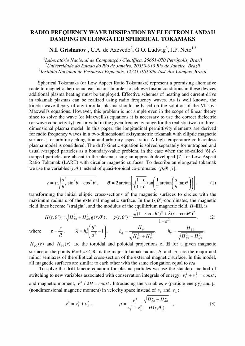
Spherical Tokamaks (or Low Aspect Ratio Tokamaks) represent a promising alternativeroute to magnetic thermonuclear fusion. In order to achieve fusion conditions in these devicesadditional plasma heating must be employed. Effective schemes of heating and current drivein tokamak plasmas can be realized using radio frequency waves. As is well known, thekinetic wave theory of any toroidal plasma should be based on the solution of the Vlasov-Maxwell's equations. However, this problem is not simple even in the scope of linear theorysince to solve the wave (or Maxwell's) equations it is necessary to use the correct dielectric(or wave conductivity) tensor valid in the given frequency range for the realistic two- or three-dimensional plasma model. In this paper, the longitudinal permittivity elements are derivedfor radio frequency waves in a two-dimensional axisymmetric tokamak with elliptic magneticsurfaces, for arbitrary elongation and arbitrary aspect ratio. A high-temperature collisionlessplasma model is considered. The drift-kinetic equation is solved separately for untrapped andusual t-trapped particles as a boundary-value problem, in the case when the so-called [6] d-trapped particles are absent in the plasma, using an approach developed [7] for Low AspectRatio Tokamak (LART) with circular magnetic surfaces. To describe an elongated tokamakwe use the variables (r,θ’) instead of quasi-toroidal co-ordinates (ρ,θ) [7]:
θθρ 222
2
cossin +=b
ar ,
+−= θ
εεθ tanarctan
2
1tan
1
1arctan2'
b
a, (1)
transforming the initial elliptic cross-sections of the magnetic surfaces to circles with themaximum radius a of the external magnetic surface. In the (r,θ’)-coordinates, the magneticfield lines become "straight", and the modulus of the equilibrium magnetic field, H=|H|, is
)',()',( 20
20 θθ θφ rgHHrH += ,
2
22
1
)'cos()'cos1()',(
εθελθε
θ−
−+−=rg , (2)
whereR
r=ε ,
−= 1
2
22
a
bhθλ ,
20
20
0
θφ
φφ
HH
Hh
+= ,
20
20
0
θφ
θθ
HH
Hh
+= ,
H rϕ 0 ( ) and H rθ 0 ( ) are the toroidal and poloidal projections of H for a given magnetic
surface at the points θ = ± π/2; R is the major tokamak radius; b and a are the major andminor semiaxes of the elliptical cross-section of the external magnetic surface. In this model,all magnetic surfaces are similar to each other with the same elongation equal to b/a.
To solve the drift-kinetic equation for plasma particles we use the standard method ofswitching to new variables associated with conservation integrals of energy, v v const||
2 2+ =⊥ ,
and magnetic moment, v H const⊥ =2 2/ . Introducing the variables v (particle energy) and µ (nondimensional magnetic moment) in velocity space instead of v || and v⊥ :
22||
2⊥+= vvv ,
)',(
20
20
22||
2
θµ θφ
rH
HH
vv
v +
+=
⊥
⊥ , (3)
the perturbed distribution function of plasma particles (any kind of ions and electrons) can befound as
∑±=
⊥ +−=1
|| )exp(),,',(),,,',,(s
s intivrfvvrtf φωµθφθ ,
where we have taken into account that the problem is uniform in both time t and toroidalangle φ. In zero order over the magnetization parameters (i.e., neglecting finite Larmor radiuseffects), the linearized drift-kinetic equation for harmonics fs can be written as
)',(12')',(
)',(1
)1(
)'cos1(2
||
5.12
2
θµωθθ
θµε
θε
θθ
rgvMh
FerEf
vh
sriinqf
f
rg
rg
T
sss ⋅−=−
+
∂∂⋅−
−−
, (4)
where
−=
2
2
35.1exp
TT v
v
v
NF
π,
M
TvT
22 = ,21 ε
ε
θ
φ
−
⋅=
h
hg ,
E|| = hE ⋅ is the parallel (to H) electric field component; the steady-state distribution functionF is given as a Maxwellian with the particle density N, temperature T, charge e and mass M.The index of particles species (ions and electrons) is omitted in Eqs. (4). By the indexes
1±=s for fs, we distinguish the perturbed distribution functions with positive and negative
values of the parallel velocity )',(g-1|| θµ rsvv ⋅= relative to H.
Thus, the initial drift-kinetic equation is reduced to a first order differential equationwith respect to the poloidal angle θ’, where the variables r, v, µ (as well as R, a, b, q, N, T)appear as parameters. After solving Eq. (4), the longitudinal (parallel to H) component of thecurrent density j|| = hj ⋅ can be expressed as
∑ ∫ ∫± ∞
=1
0
)',(/1
0
3|| ),,',()',()',(
s
rg
s dvdvrfvsregrjθ
µµθθπθ . (5)
Depending on µ and θ’ the phase space of plasma particles must be split in the phasespace of untrapped, t-trapped and d-trapped particles according to the following inequalities:
uµµ ≤≤0 πθπ ≤≤− ' - for untrapped particles (6)
tu µµµ ≤≤ tt θθθ ≤≤− ' - for t-trapped particles (7)
dt µµµ ≤≤ dt θθθ −≤≤− ' - for d-trapped particles (8)
dt µµµ ≤≤ td θθθ ≤≤ ' - for d-trapped particles (9)
where [analyzing the condition 0)',(|| =θµv ]
µ ελu = −
+1
1, µ ε
λt = ++
1
1, µ ε λ
λ εd = ++
12
,
and the reflection points tθ± and dθ± for t- and d-trapped particles are, respectively,
−−++
−+
+−++±=±
222
222
22
2
11
1
)(
)1()1(arccos
µελε
ελελλε
ελλεθ t . (10)
−−++
−+
++++±=±
222
222
22
2
11
1
)(
)1()1(arccos
µελε
ελελλε
ελλεθ d (11)
Now, we solve Eq. (4) for untrapped and usual t-trapped particles only, under thecondition when the d-particles are absent, i.e., considering the LART magnetic fieldconfiguration as a system with one minimum of H(r,θ’). In this case, the criterion [6] of d-
particle existence, ε < λ or εεε /)1(1/ 22 −++> qab , cannot be satisfied.
The solution of Eq. (4) must be found for the specific boundary conditions of the trappedand untrapped particles. For untrapped particles we use the periodicity of fs over θ’. Whereas,the boundary condition for the t-trapped particles is the continuity of fs at the correspondingstop-points, Eq. (10). As a result, we seek the perturbed distribution functions of untrapped,
usf , and t-trapped, t
sf , particles as
∑±∞
−+=
p u
ups
us inq
Tnqpiff '
)'()(2exp, θθτπ , ∑
∞
−=
�
p t
tps
ts inq
Tpiff '
)'(2exp, θθτπ (12)
where p is the number of resonance bounces,
∫ −−⋅⋅−=
'
02
2
),(1)cos1(
),()1()'(
θ
ηµηεηηεθτrg
drg(13)
is the new time-like variable (instead of θ’) describing the bounce-periodic motion ofuntrapped and t-trapped particles along the magnetic field line with the corresponding periods
)(2 πτ=uT and )(4 ttT θτ= . The Fourier harmonics upsf , and t
psf , for untrapped and t-trapped
particles can be readily derived after the corresponding bounce averaging.To evaluate the dielectric tensor elements we use the Fourier expansions of the current
density and electric field over the poloidal angle θ’:
∑±∞
=− m
m imjrg
j)'exp(
)',()1(
)'(||2
|| θθε
θ, ∑
±∞
=−
−'
'||2
2
|| )''exp()'cos1(
)',()1()'(
m
m imErg
E θθε
θεθ (14)
As a result, the whole spectrum of electric field, '||mE , is present in the given m-th harmonic
mj|| of the current density:
∑∑±∞±∞
+=='
'||
',||,
',||,
'
'||
',|||| )(
4
m
mmmt
mmu
m
mmmm EEji εεε
ωπ
, (15)
where ',||,
mmuε and ',
||,mm
tε are the separate contributions of untrapped and t-trapped particles,
respectively, to the longitudinal (parallel) permittivity elements:
[ ]∑ ∫∞
−∞=
+++
=p
ppp
mp
mp
T
pmmu
u
duWuiunqp
CC
vh
r µ
θ
µππτ
πω
ε0
322
'
322
22',
.|| )(221)(
)(, (16)
[ ]∑ ∫∞
=
++=1 0
32'2322
22',
.|| )(221)(2
pppp
mp
mp
t
T
pmmt
t
dvWvivDDpvh
r µ
θ
µπθτ
πω
ε . (17)
Here we have used the following definitions
M
Nep
22 4πω = ,
ππτεω
θ Tp vnqph
ru
||
)(1 2
+−= ,
πθτεω
θ T
tp pvh
rv
)(12
2−= ,
∫
+−+=
π
ηπτητπη
0 )(
)()()(cos dnqpnqmC m
p ,
+= ∫−
ztz dte
iezW
0
22 21)(
π,
∫∫
++−+
−+= −
tt
dpnqmdpnqmDt
p
t
mp
θθ
ηθτηπτηη
θτηπτη
0
1
0 )(2
)()(cos)1(
)(2
)()(cos .
It should be noted that Eqs. (16, 17) describe the contribution of any kind of untrappedand trapped particles to the dielectric elements. The corresponding expressions for plasmaelectrons and ions can be obtained from (16, 17) replacing T, N, M, e by the electron Te, Ne,me, ee and ion Ti, Ni, Mi, ei parameters, respectively. To obtain the total expressions of thepermittivity elements, as usual, it is necessary to carry out the summation over all species ofplasma particles.
One of the main mechanisms of radio frequency plasma heating is the electron Landaudamping of waves due to the Cherenkov resonance interaction of ||E with the trapped and
untrapped electrons. Cherenkov resonance conditions are different for trapped and untrappedparticles in the LART plasmas and have nothing in common with the wave-particle resonancecondition in cylindrical magnetized plasmas. Another important feature of tokamak plasmas isthe contributions of all '
||mE -harmonics to the given mj|| -harmonic, Eq. (15). As a result, after
averaging in time and poloidal angle, the wave power absorbed, )Re( *|||| jEP ⋅= , due to
trapped and untrapped electrons can be estimated by the expression
( )( )∑∑±∞ ±∞
++=m m
mmmmmmt
mmu EEEEP
'
'||||
'||||
',||,
',||, ImImReReImIm
8εε
πω
, (18)
where ',||,Im mm
uε and ',||,Im mm
tε are the contributions of untrapped and t-trapped electrons to the
imaginary part of the longitudinal permittivity elements: ',||,
',||,
',|| ImImIm mm
tmm
umm εεε += . In the
simplest case of Toroidicity-induced Alfvén Eigenmodes (TAEs) [8], describing the couplingof only two harmonics with mo and mo-1, the width mo, mo-1 should also be accounted in Eq.(15) to estimate the TAEs absorption by the trapped and untrapped electrons. As a result, thedissipated power of TAEs by electron Landau damping is
( )∑−=
−−− ++=o
o
oooooo
m
mm
mmmmmmmmm EEEEEP1
1||||
1||||
1,||
2||
',|| ImImReReIm
4||Im
8ε
πωε
πω
(19)
where 2||
2||
2|| )(Im)(Re|| mmm EEE += . Note that the non-diagonal elements '
',|| | mm
mm≠ε are
characteristic only of toroidal plasmas. For the one-mode (cylindrical) approximation, whenm=m’=mo, the non-diagonal elements vanish, i.e., '
',|| |Im mm
mm≠ε = 0, and Eqs. (18, 19) reduce
to the well-known expression2
||,
|| ||Im8
mmm EP επ
ω= .
The longitudinal permittivity elements evaluated in this paper are suitable for both largeand low aspect ratio tokamaks with elliptic magnetic surfaces and valid in a wide range ofwave frequencies, mode numbers, and plasma parameters. The expressions (16, 17) have anatural limit to the corresponding results [7] for LART plasmas with circular magneticsurfaces, if b=a and 0→λ . Since the drift kinetic equation is solved as a boundary-valueproblem, the longitudinal permittivity elements (16, 17) are suitable for studying waveprocesses with a regular frequency, such as wave propagation and dissipation during plasmaheating and current drive generation, with wave frequency given, e.g., by the antenna-generator system.
References[1] Y-K.M. Peng, D.J. Strickler, Nuclear Fusion, 26 769, 1986.[2] D.C. Robinson, Fusion Energy and Plasma Physics, World Scientific Press, 601, 1987.[3] A. Sykes et al, Plasma Phys. Control. Fusion, 39 247, 1997.[4] A. Sykes and MAST team, X Int. Congress Plasma Phys. & 42 Annual Meeting of theDPP-APS, 23-27 October 2000, Quebec, Canada, paper GI1-2.[5] S.M. Kaye and NSTX Research Team, Ibiden, paper GI1-3.[6] N.I. Grishanov, C.A. Azevedo, A.S. Assis, Plasma Phys.Control. Fusion, 41 645, 1999.[7] N.I. Grishanov, C.A. Azevedo, J.P. Neto, Plasma Phys. Control. Fusion, August, 2001.[8] C.Z. Cheng, M.S. Chance, Phys. Fluids, 29 3695, 1986.