Embed Size (px)
Citation preview

SAI Hydraulics, Inc.3905 W. 9th StreetTrainer, PA 19061(610) 497-0190 Fax (610) 497-0194
SAI Hydraulics Canada Ltd.6105 Boulevard CoutureSt. Leonard, PQ H1P3G7(514) 323-4552 Fax (514) 323-8780
www.saihyd.com [email protected]
MILLENNIUM SERIESMILLENNIUM SERIESMILLENNIUM SERIESMILLENNIUM SERIESMILLENNIUM SERIESMILLENNIUM SERIESMILLENNIUM SERIESMILLENNIUM SERIESMILLENNIUM SERIESMILLENNIUM SERIESThe REB Series Planetary Gearboxes described in this cata-log are designed and manufactured to meet all customer re-quirements. Their modular structure accomodates a wide rangeand ratios, input & output flanges, accessories and custom-ized solutions. The information provided in this catalog andprompt availablity of our technical staff allow our customers toconfidently choose the best solution for each application.
Total quality has always been our main objective.Our vast experience and capability to provide di-versified solutions to a wide range of industries overthe years have greatly contributed to this achieve-ment.
Another key element is our team work. All com-pany departments operate in compliance with theQuality System standards to attain a common goal:Total Customer Satisfaction. This commitment hasplaced us at the forefront of its sector as a leadingmanufacturer and supplier of planetary gears formany applications.
The high degree of design and manufacturing technology inour products is recognized by the ISO 9001 quality certification.Achievement of this certification further improved our productsand customer services; reinforcing our strong position in keymarkets and diverse sectors, such as windmills, cranes, liftingequipment and earth machinery worldwide.
Det Norske VeritasQuality System Certificate
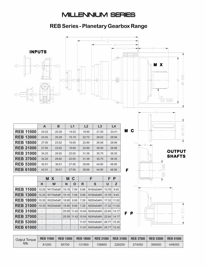
REB Series - Planetary Gearbox Range
M XM XM XM XM X
M CM CM CM CM C
FFFFF
F PF PF PF PF P
INPUTSINPUTSINPUTSINPUTSINPUTS
OUTPUTOUTPUTOUTPUTOUTPUTOUTPUTSHAFTSSHAFTSSHAFTSSHAFTSSHAFTS
MILLENNIUM SERIESMILLENNIUM SERIESMILLENNIUM SERIESMILLENNIUM SERIESMILLENNIUM SERIESMILLENNIUM SERIESMILLENNIUM SERIESMILLENNIUM SERIESMILLENNIUM SERIESMILLENNIUM SERIES
euqroTtuptuObl/tf
00011BER 00031BER 00081BER 00012BER 00013BER 00073BER 00035BER 00016BER00218 00759 059131 008851 002622 050472 050093 050844
XM CM F PFH W N O R S U Z
00011BER 02.21 f8x5x071W 61.51 90.7 89.5 H9x5x061N 87.31 54.9
00031BER 02.21 f8x5x071W 61.51 90.7 89.5 H9x5x061N 87.31 54.9
00081BER 53.51 f8x5x022W 09.81 60.9 82.7 H9x5x002N 23.71 20.11
00012BER 53.51 f8x5x022W 09.81 60.9 82.7 H9x5x002N 23.71 20.11
00013BER - - 95.52 24.11 40.01 H9x5x042N 46.22 71.41
00073BER - - 95.52 24.11 40.01 H9x5x042N 46.22 71.41
00035BER - - - - 18.11 H9x8x003N 77.62 53.51
00016BER - - - - 18.11 H9x8x003N 77.62 53.51
A B 1L 2L 3L 4L00011BER 20.42 82.02 25.41 09.81 05.12 14.32
00031BER 20.42 82.02 91.51 27.22 20.62 65.82
00081BER 59.72 26.32 56.61 98.22 65.62 69.82
00012BER 59.72 26.32 56.61 98.22 65.62 69.82
00013BER 52.43 29.92 50.22 83.13 57.53 53.83
00073BER 52.43 29.92 50.22 83.13 57.53 53.83
00035BER 19.24 16.63 65.72 66.83 09.44 65.84
00016BER 19.24 16.63 65.72 66.83 09.44 65.84
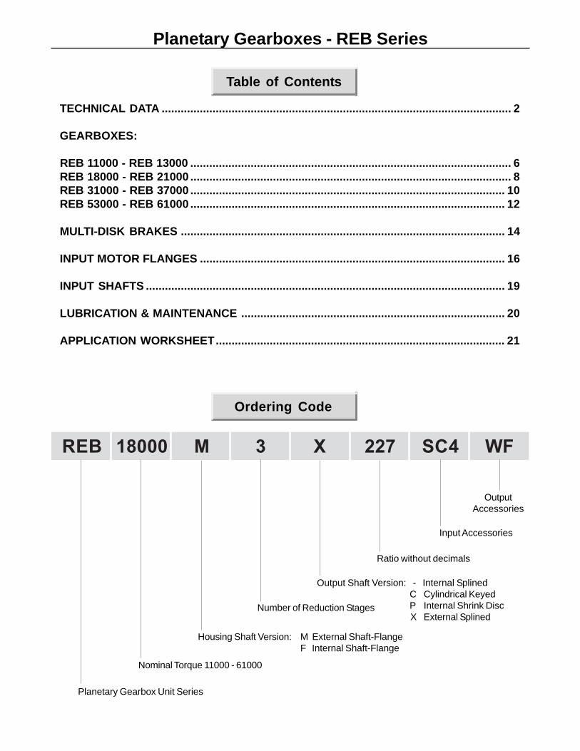
Planetary Gearboxes - REB Series
BER 00081 M 3 X 722 4CS FW
Table of Contents
Ordering Code
TECHNICAL DATA .............................................................................................................. 2
GEARBOXES:
REB 11000 - REB 13000 ..................................................................................................... 6REB 18000 - REB 21000 ..................................................................................................... 8REB 31000 - REB 37000 ................................................................................................... 10REB 53000 - REB 61000 ................................................................................................... 12
MULTI-DISK BRAKES ...................................................................................................... 14
INPUT MOTOR FLANGES ................................................................................................ 16
INPUT SHAFTS ................................................................................................................. 19
LUBRICATION & MAINTENANCE ................................................................................... 20
APPLICATION WORKSHEET........................................................................................... 21
Planetary Gearbox Unit Series
Nominal Torque 11000 - 61000
Housing Shaft Version: M External Shaft-FlangeF Internal Shaft-Flange
Number of Reduction Stages
Output Shaft Version: - Internal SplinedC Cylindrical KeyedP Internal Shrink DiscX External Splined
Ratio without decimals
Input Accessories
OutputAccessories
2
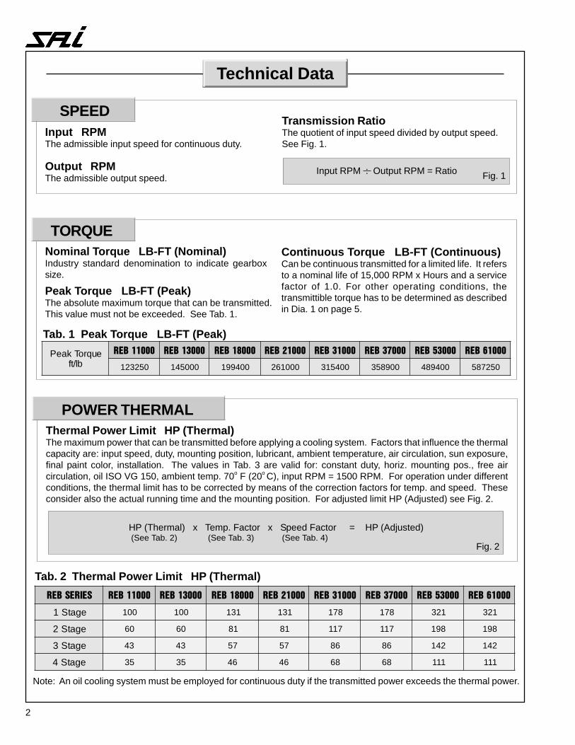
Technical Data
Input RPMThe admissible input speed for continuous duty.
Output RPMThe admissible output speed.
Transmission RatioThe quotient of input speed divided by output speed.See Fig. 1.
Tab. 1 Peak Torque LB-FT (Peak)
Input RPM : Output RPM = Ratio Fig. 1
Nominal Torque LB-FT (Nominal)Industry standard denomination to indicate gearboxsize.
Continuous Torque LB-FT (Continuous)Can be continuous transmitted for a limited life. It refersto a nominal life of 15,000 RPM x Hours and a servicefactor of 1.0. For other operating conditions, thetransmittible torque has to be determined as describedin Dia. 1 on page 5.
Peak Torque LB-FT (Peak)The absolute maximum torque that can be transmitted.This value must not be exceeded. See Tab. 1.
TORQUE
POWER THERMALThermal Power Limit HP (Thermal)The maximum power that can be transmitted before applying a cooling system. Factors that influence the thermalcapacity are: input speed, duty, mounting position, lubricant, ambient temperature, air circulation, sun exposure,final paint color, installation. The values in Tab. 3 are valid for: constant duty, horiz. mounting pos., free aircirculation, oil ISO VG 150, ambient temp. 70o F (20o C), input RPM = 1500 RPM. For operation under differentconditions, the thermal limit has to be corrected by means of the correction factors for temp. and speed. Theseconsider also the actual running time and the mounting position. For adjusted limit HP (Adjusted) see Fig. 2.
HP (Thermal) x Temp. Factor x Speed Factor = HP (Adjusted) (See Tab. 2) (See Tab. 3) (See Tab. 4)
Fig. 2
Tab. 2 Thermal Power Limit HP (Thermal)
��������� �������� �������� ������� ������� �������� �������� �������� ���� ���
egatS1 001 001 131 131 871 871 123 123
egatS2 06 06 18 18 711 711 891 891
egatS3 34 34 75 75 68 68 241 241
egatS4 53 53 64 64 86 86 111 111
euqroTkaePbl/tf
�������� �������� �������� �������� �������� ������� ������� ��������
052321 000541 004991 000162 004513 009853 004984 052785
SPEED
Note: An oil cooling system must be employed for continuous duty if the transmitted power exceeds the thermal power.
3
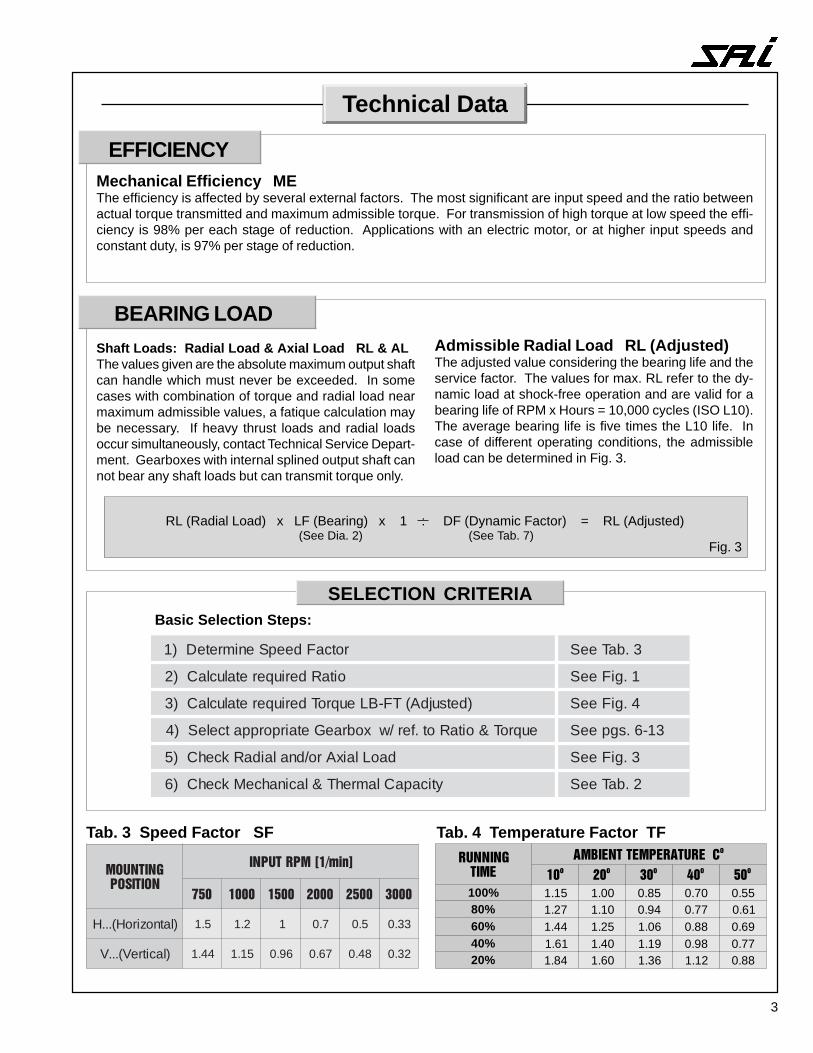
Technical Data
EFFICIENCYMechanical Efficiency METhe efficiency is affected by several external factors. The most significant are input speed and the ratio betweenactual torque transmitted and maximum admissible torque. For transmission of high torque at low speed the effi-ciency is 98% per each stage of reduction. Applications with an electric motor, or at higher input speeds andconstant duty, is 97% per stage of reduction.
BEARING LOAD
Shaft Loads: Radial Load & Axial Load RL & ALThe values given are the absolute maximum output shaftcan handle which must never be exceeded. In somecases with combination of torque and radial load nearmaximum admissible values, a fatique calculation maybe necessary. If heavy thrust loads and radial loadsoccur simultaneously, contact Technical Service Depart-ment. Gearboxes with internal splined output shaft cannot bear any shaft loads but can transmit torque only.
Admissible Radial Load RL (Adjusted)The adjusted value considering the bearing life and theservice factor. The values for max. RL refer to the dy-namic load at shock-free operation and are valid for abearing life of RPM x Hours = 10,000 cycles (ISO L10).The average bearing life is five times the L10 life. Incase of different operating conditions, the admissibleload can be determined in Fig. 3.
RL (Radial Load) x LF (Bearing) x 1 : DF (Dynamic Factor) = RL (Adjusted) (See Dia. 2) (See Tab. 7)
Fig. 3
�����������
��������������� �
��
��
��
��
��
%001 51.1 00.1 58.0 07.0 55.0%08 72.1 01.1 49.0 77.0 16.0%06 44.1 52.1 60.1 88.0 96.0%04 16.1 04.1 91.1 89.0 77.0%02 48.1 06.1 63.1 21.1 88.0
Tab. 4 Temperature Factor TFTab. 3 Speed Factor SF
���������������
�������������
��� ���� ���� ���� ���� ����
)latnoziroH(...H 5.1 2.1 1 7.0 5.0 33.0
)lacitreV(...V 44.1 51.1 69.0 76.0 84.0 23.0
Basic Selection Steps:
SELECTION CRITERIA
rotcaFdeepSenimreteD)1 3.baTeeS
oitaRderiuqeretaluclaC)2 1.giFeeS
)detsujdA(TF-BLeuqroTderiuqeretaluclaC)3 4.giFeeS
euqroT&oitaRot.fer/wxobraeGetairporppatceleS)4 31-6.sgpeeS
daoLlaixAro/dnalaidaRkcehC)5 3.giFeeS
yticapaClamrehT&lacinahceMkcehC)6 2.baTeeS
4
Technical Data
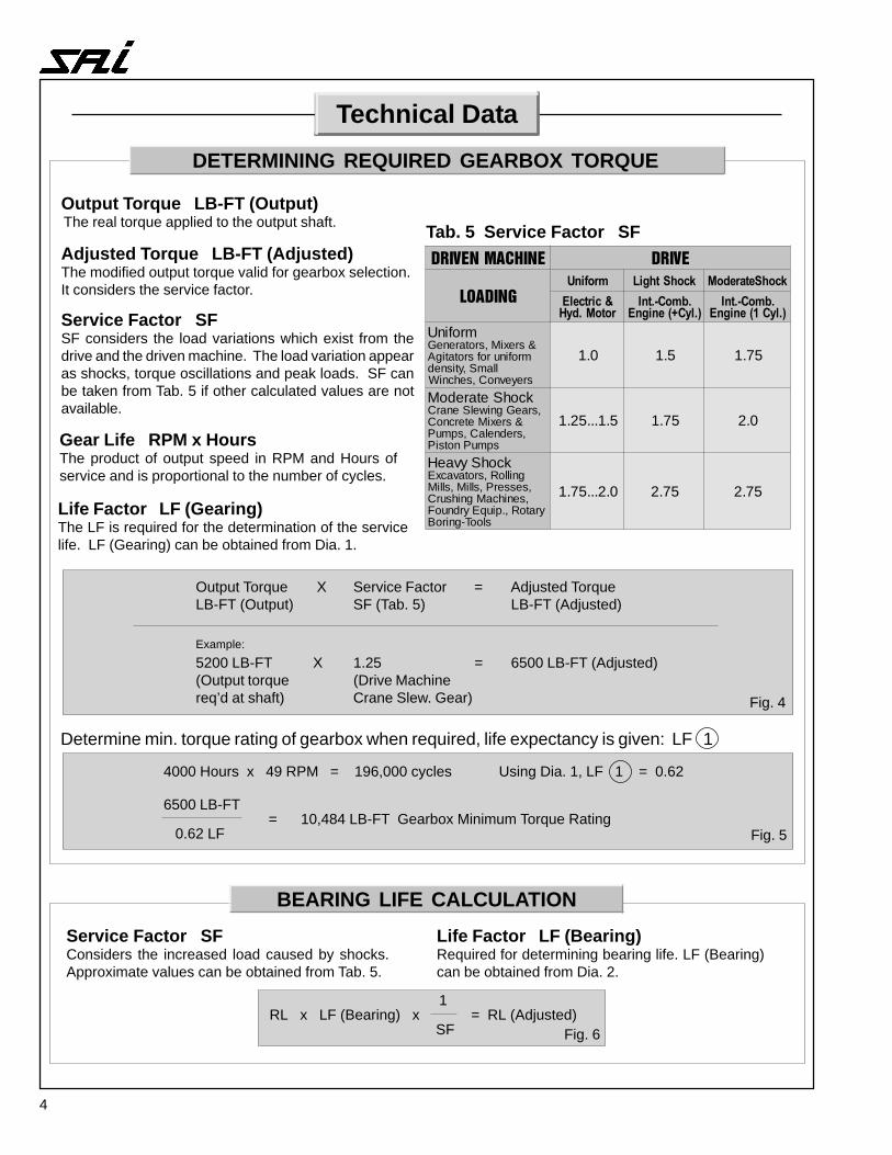
Output Torque LB-FT (Output) The real torque applied to the output shaft.
Adjusted Torque LB-FT (Adjusted)The modified output torque valid for gearbox selection.It considers the service factor.
Service Factor SFSF considers the load variations which exist from thedrive and the driven machine. The load variation appearas shocks, torque oscillations and peak loads. SF canbe taken from Tab. 5 if other calculated values are notavailable.
Output Torque X Service Factor = Adjusted TorqueLB-FT (Output) SF (Tab. 5) LB-FT (Adjusted)
Example:
5200 LB-FT X 1.25 = 6500 LB-FT (Adjusted)(Output torque (Drive Machinereq’d at shaft) Crane Slew. Gear)
Gear Life RPM x HoursThe product of output speed in RPM and Hours ofservice and is proportional to the number of cycles.
Life Factor LF (Gearing)The LF is required for the determination of the servicelife. LF (Gearing) can be obtained from Dia. 1.
Tab. 5 Service Factor SF
Fig. 4
DETERMINING REQUIRED GEARBOX TORQUE
����������� ���
�����
������� ���� �� �����������
����������������
�������������������� ��
��������������� ���� ��
mrofinU&srexiM,srotareneG
mrofinurofsrotatigAllamS,ytisned
sreyevnoC,sehcniW
0.1 5.1 57.1
kcohSetaredoM,sraeGgniwelSenarC
&srexiMetercnoC,srednelaC,spmuP
spmuPnotsiP
5.1...52.1 57.1 0.2
kcohSyvaeHgnilloR,srotavacxE
,sesserP,slliM,slliM,senihcaMgnihsurC
yratoR,.piuqEyrdnuoFslooT-gniroB
0.2...57.1 57.2 57.2
Determine min. torque rating of gearbox when required, life expectancy is given: LF 1
4000 Hours x 49 RPM = 196,000 cycles Using Dia. 1, LF 1 = 0.62
6500 LB-FT= 10,484 LB-FT Gearbox Minimum Torque Rating
0.62 LF Fig. 5
Service Factor SFConsiders the increased load caused by shocks.Approximate values can be obtained from Tab. 5.
Life Factor LF (Bearing)Required for determining bearing life. LF (Bearing)can be obtained from Dia. 2.
1RL x LF (Bearing) x = RL (Adjusted)
SF Fig. 6
BEARING LIFE CALCULATION
5
Technical Data
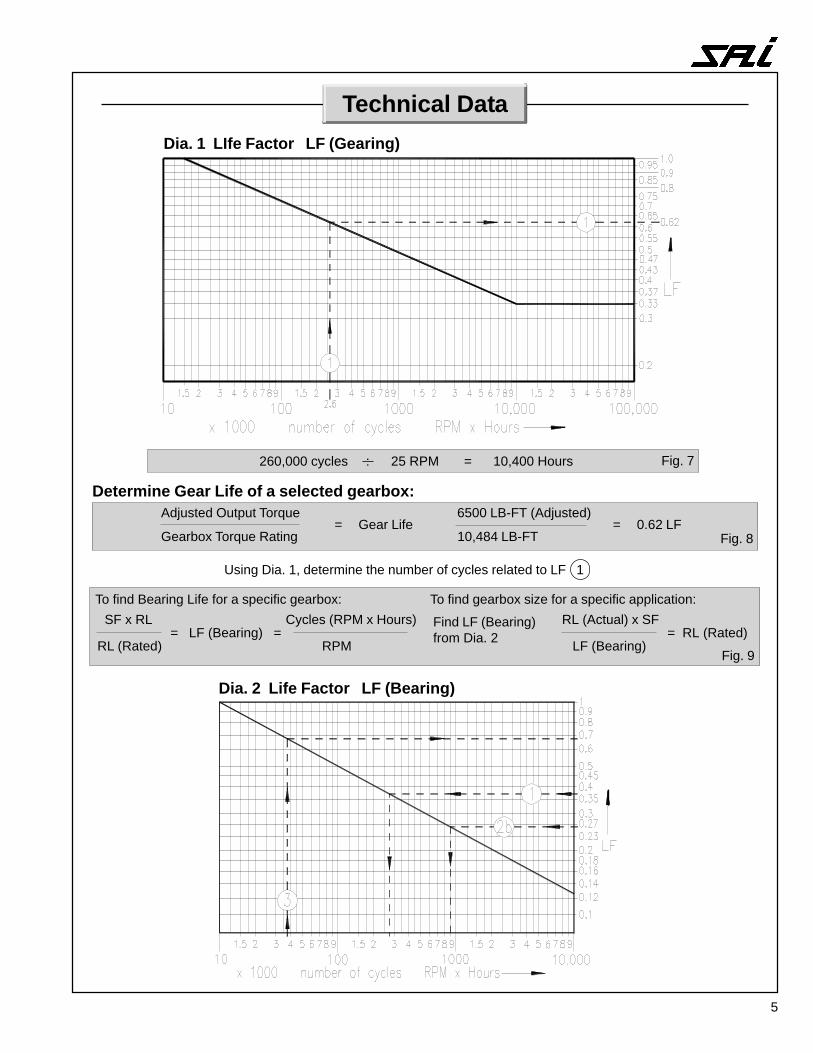
Dia. 2 Life Factor LF (Bearing)
To find Bearing Life for a specific gearbox:
SF x RL = LF (Bearing) =
RL (Rated)
Cycles (RPM x Hours)
RPM
To find gearbox size for a specific application:
Find LF (Bearing)from Dia. 2
RL (Actual) x SF = RL (Rated) LF (Bearing)
Fig. 9
Dia. 1 LIfe Factor LF (Gearing)
260,000 cycles : 25 RPM = 10,400 Hours
Determine Gear Life of a selected gearbox:Adjusted Output Torque 6500 LB-FT (Adjusted)
= Gear Life = 0.62 LFGearbox Torque Rating 10,484 LB-FT
Using Dia. 1, determine the number of cycles related to LF 1
Fig. 7
Fig. 8
6
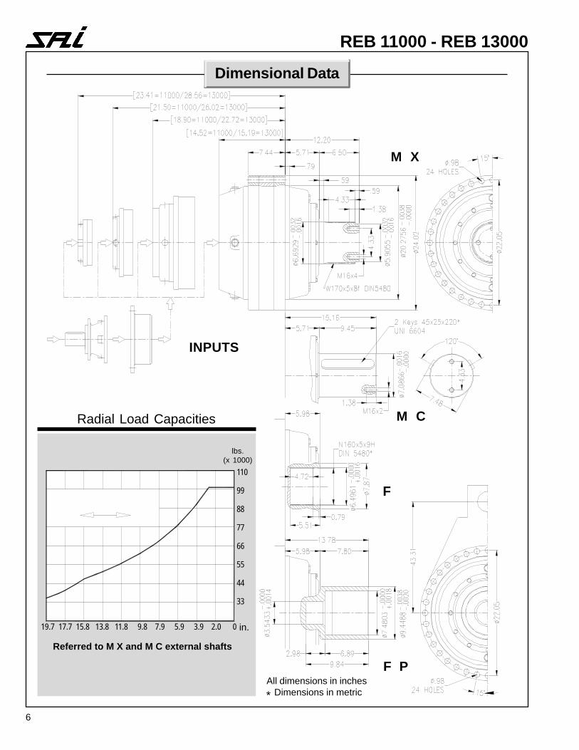
REB 11000 - REB 13000
Dimensional Data
M X
M C
F
F P
INPUTS
Radial Load Capacities
lbs.(x 1000)
110
99
88
77
66
55
44
33
19.7 17.7 15.8 13.8 11.8 9.8 7.9 5.9 3.9 2.0 0
Referred to M X and M C external shafts
in.
All dimensions in inches Dimensions in metric*

7
REB 11000 - REB 13000
Technical Data
00031BER-00011BER00011 00031
soitaR.tnoCeuqroT
=rHxveRsrh00002
.tnoCeuqroT
=rHxveRsrh00003
kaePeuqroT soitaR
.tnoCeuqroT
=rHxveRsrh00002
.tnoCeuqroT
=rHxveRsrh00003
kaePeuqroT
P1F,1F,X1M,C1M
1 egatS
90.4 A A A 38.3 A A A
52.5 B B B 04.4 B B B
32.6 C C C
P2F,2F,X2M,C2M
2 egatS
63.61 A A A 33.51 A A A
00.12 B B B 06.71 B B B
03.72 B B B
04.23 C C C
49.83 C C C
P3F,3F,X3M,C3M
3 egatS
64.27 A A A 15.45 A A A
99.29 B B B 17.56 A A A
98.021 B B B 24.57 B B B
13.541 B B B 68.58 A A A
43.851 B B B 65.89 B B B
13.091 B B B 94.301 A A A
68.522 C C C 08.811 B B B
P4F,4F,X4M,C4M
4 egatS
29.892 A A A 88.422 A A A
05.193 A A A 66.182 A A A
97.434 A A A 15.933 A A A
53.094 A A A 42.593 A A A
54.965 A A A 39.624 A A A
31.356 B B B 24.674 A A A
57.057 B B B 91.515 A A A
70.818 B B B 58.645 B B B
68.178 B B B 63.195 B B B
40.059 B B B 25.226 A A A
37.4301 C C C 63.057 A A A
25.7211 C C C 13.168 B B B
91.5531 C C C
bl/tfgnitaReuqroT00368=A00246=B00405=C
00218=A00206=B05179=C
052321=A003701=B00078=C
005101=A00759=B
00759=A00298=B
000541=A056041=B
8
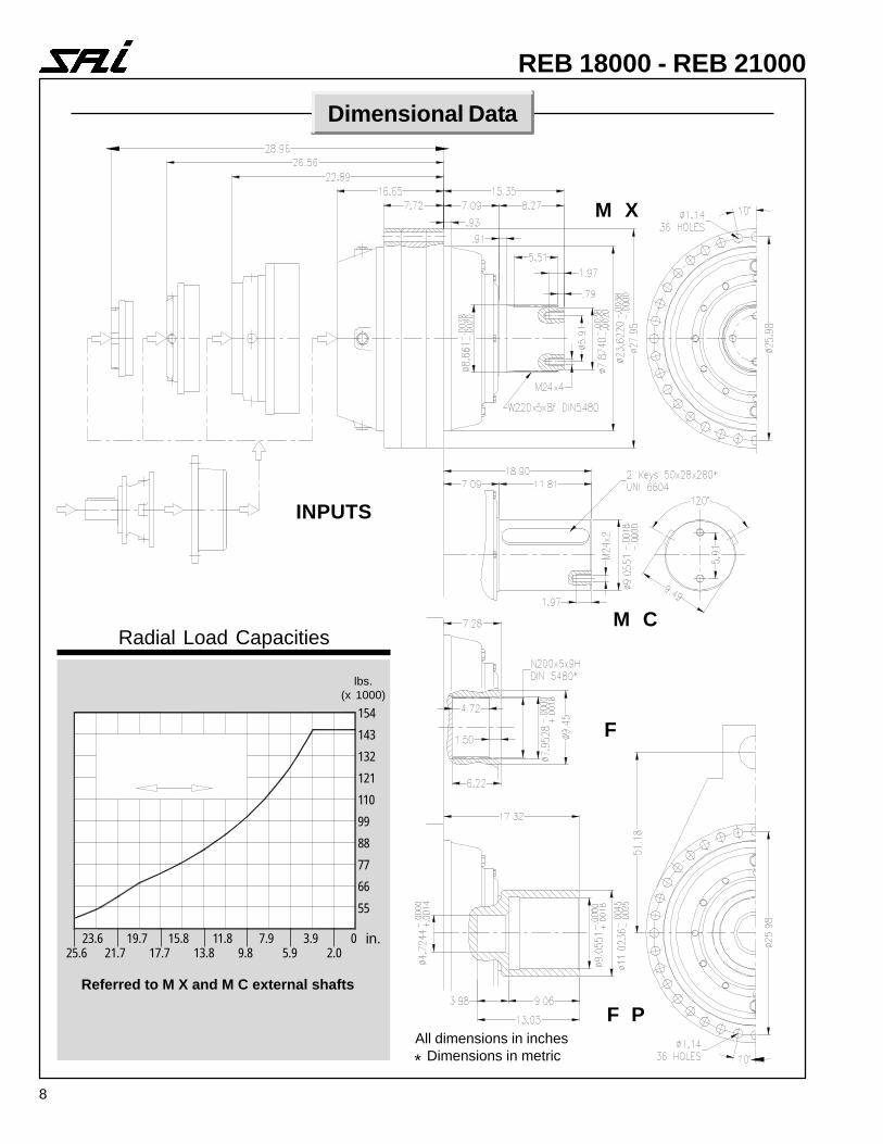
REB 18000 - REB 21000
Dimensional Data
M X
M C
F
F P
INPUTS
Radial Load Capacities
lbs.(x 1000)
154
143
132
121
110
99
88
77
66
55
25.6 21.7 17.7 13.8 9.8 5.9 2.0
Referred to M X and M C external shafts
23.6 19.7 15.8 11.8 7.9 3.9 0
All dimensions in inches Dimensions in metric*
in.
9
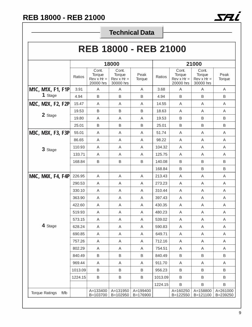
REB 18000 - REB 21000
Technical Data
00012BER-00081BER00081 00012
soitaR.tnoCeuqroT
=rHxveRsrh00002
.tnoCeuqroT
=rHxveRsrh00003
kaePeuqroT soitaR
.tnoCeuqroT
=rHxveRsrh00002
.tnoCeuqroT
=rHxveRsrh00003
kaePeuqroT
P1F,1F,X1M,C1M1 egatS
19.3 A A A 86.3 A A A
49.4 B B B 49.4 B B B
P2F,2F,X2M,C2M
2 egatS
74.51 A A A 55.41 A A A
35.91 B B B 36.81 A A A
08.91 A A A 35.91 B B B
10.52 B B B 10.52 B B B
P3F,3F,X3M,C3M
3 egatS
10.55 A A A 47.15 A A A
56.68 A A A 22.89 A A A
39.011 A A A 23.401 A A A
17.331 A A A 57.521 A A A
48.861 B B B 80.041 B B B
48.861 B B B
P4F,4F,X4M,C4M
4 egatS
59.622 A A A 34.312 A A A
35.092 A A A 32.372 A A A
01.033 A A A 44.013 A A A
09.363 A A A 34.793 A A A
06.224 A A A 53.034 A A A
39.915 A A A 32.084 A A A
51.375 A A A 20.935 A A A
42.826 A A A 38.095 A A A
58.096 A A A 17.946 A A A
62.757 A A A 61.217 A A A
92.208 A A A 15.457 A A A
94.048 B B B 94.048 B B B
44.969 A A A 07.119 A A A
90.3101 B B B 32.659 B B B
51.4221 B B B 90.3101 B B B
51.4221 B B B
bl/tfsgnitaReuqroT 004331=A007301=B
059131=A059201=B
004991=A009671=B
052061=A055221=B
008851=A001121=B
000162=A052932=B
10
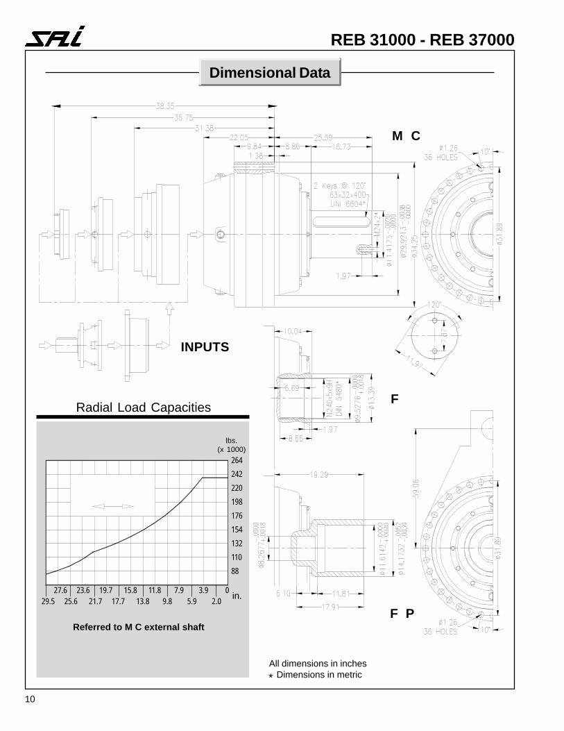
REB 31000 - REB 37000
Dimensional Data
M C
F
F P
INPUTS
Radial Load Capacities
lbs.(x 1000)
264
242
220
198
176
154
132
110
88
29.5 25.6 21.7 17.7 13.8 9.8 5.9 2.0
Referred to M C external shaft
in.27.6 23.6 19.7 15.8 11.8 7.9 3.9 0
All dimensions in inches Dimensions in metric*
11
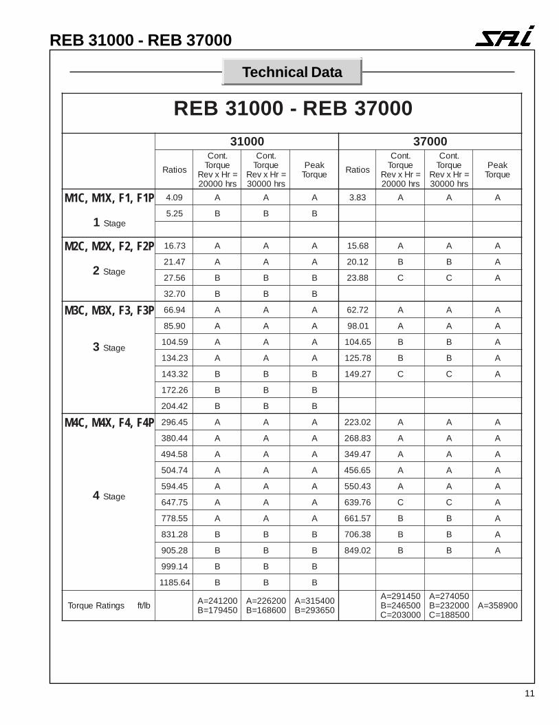
REB 31000 - REB 37000
Technical Data
00073BER-00013BER00013 00073
soitaR.tnoCeuqroT
=rHxveRsrh00002
.tnoCeuqroT
=rHxveRsrh00003
kaePeuqroT soitaR
.tnoCeuqroT
=rHxveRsrh00002
.tnoCeuqroT
=rHxveRsrh00003
kaePeuqroT
P1F,1F,X1M,C1M
1 egatS
90.4 A A A 38.3 A A A
52.5 B B B
P2F,2F,X2M,C2M
2 egatS
37.61 A A A 86.51 A A A
74.12 A A A 21.02 B B A
65.72 B B B 88.32 C C A
07.23 B B B
P3F,3F,X3M,C3M
3 egatS
49.66 A A A 27.26 A A A
09.58 A A A 10.89 A A A
95.401 A A A 56.401 B B A
32.431 A A A 87.521 B B A
23.341 B B B 72.941 C C A
62.271 B B B
24.402 B B B
P4F,4F,X4M,C4M
4 egatS
54.692 A A A 20.322 A A A
44.083 A A A 38.862 A A A
85.494 A A A 74.943 A A A
47.405 A A A 56.654 A A A
54.495 A A A 34.055 A A A
57.746 A A A 67.936 C C A
55.877 A A A 75.166 B B A
82.138 B B B 83.607 B B A
82.509 B B B 20.948 B B A
41.999 B B B
46.5811 B B B
bl/tfsgnitaReuqroT 002142=A054971=B
002622=A006861=B
004513=A056392=B
054192=A005642=B000302=C
050472=A000232=B005881=C
009853=A
12
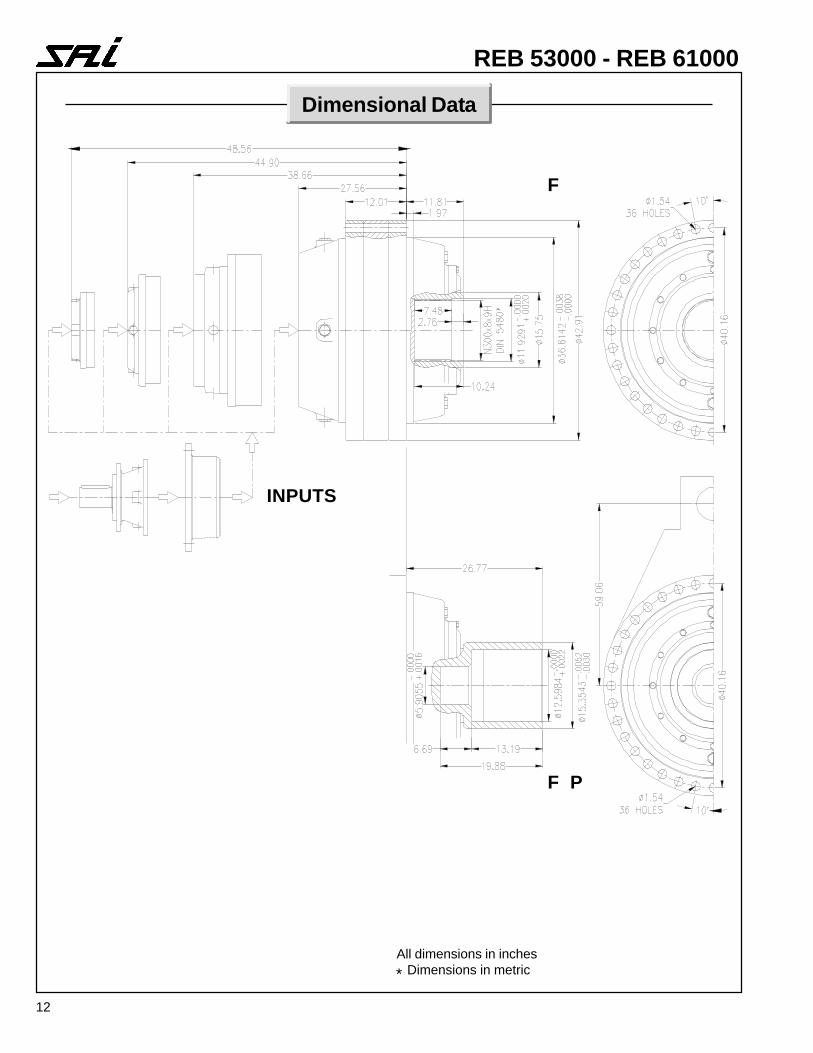
REB 53000 - REB 61000
Dimensional Data
F
F P
INPUTS
All dimensions in inches Dimensions in metric*
13
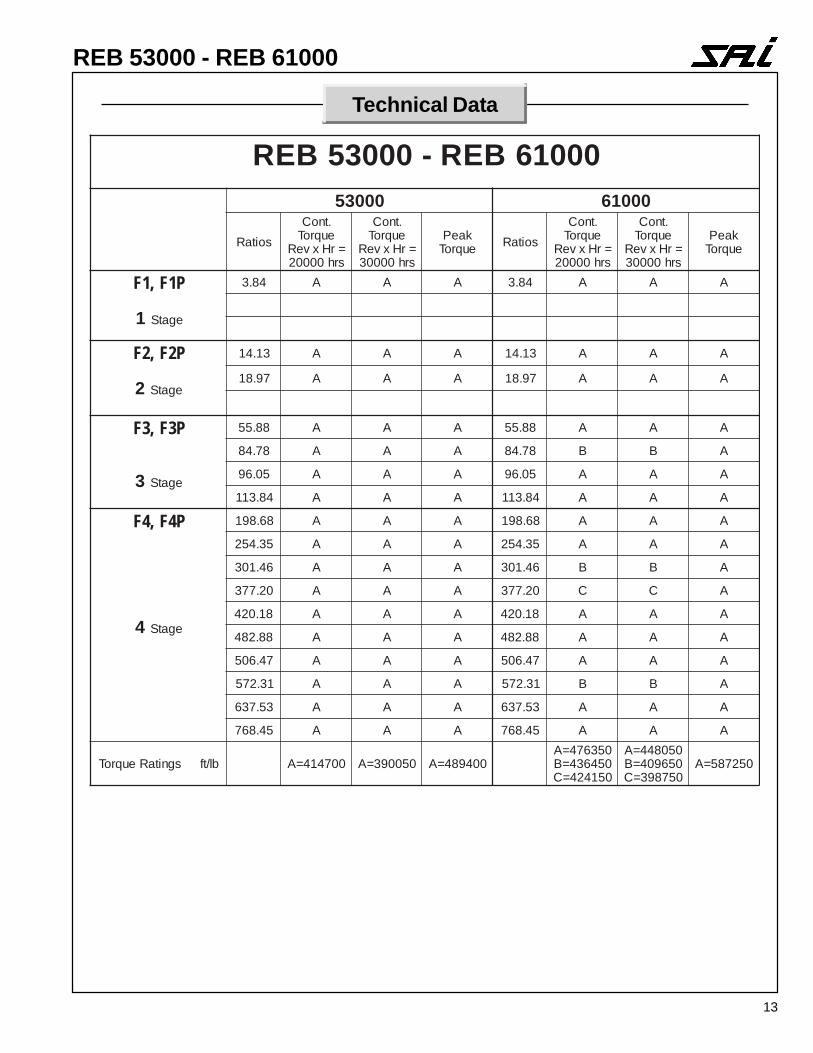
REB 53000 - REB 61000
Technical Data
00016BER-00035BER00035 00016
soitaR.tnoCeuqroT
=rHxveRsrh00002
.tnoCeuqroT
=rHxveRsrh00003
kaePeuqroT soitaR
.tnoCeuqroT
=rHxveRsrh00002
.tnoCeuqroT
=rHxveRsrh00003
kaePeuqroT
P1F,1F
1 egatS
48.3 A A A 48.3 A A A
P2F,2F
2 egatS
31.41 A A A 31.41 A A A
79.81 A A A 79.81 A A A
P3F,3F
3 egatS
88.55 A A A 88.55 A A A
87.48 A A A 87.48 B B A
50.69 A A A 50.69 A A A
48.311 A A A 48.311 A A A
P4F,4F
4 egatS
86.891 A A A 86.891 A A A
53.452 A A A 53.452 A A A
64.103 A A A 64.103 B B A
02.773 A A A 02.773 C C A
81.024 A A A 81.024 A A A
88.284 A A A 88.284 A A A
74.605 A A A 74.605 A A A
13.275 A A A 13.275 B B A
35.736 A A A 35.736 A A A
54.867 A A A 54.867 A A A
bl/tfsgnitaReuqroT 007414=A 050093=A 004984=A053674=A054634=B051424=C
050844=A056904=B057893=C
052785=A
14
Multi-Disc Brakes
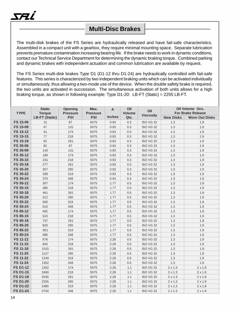
The multi-disk brakes of the FS Series are hydraulically released and have fail-safe characteristics.Assembled in a compact unit with a gearbox, they require minimal mounting space. Separate lubricationprevents premature contamination increasing bearing life. If the brake needs to work in dynamic conditions,contact our Technical Service Department for determining the dynamic braking torque. Combined parkingand dynamic brakes with independent actuation and common lubrication are available by request.
The FS Series multi-disk brakes Type D1 (D1-12 thru D1-24) are hydraulically controlled with fail-safefeatures. This series is characterized by two independent braking units which can be activated individuallyor simultaneously, thus allowing a two-mode use of the device. When the double safety brake is required,the two units are activated in succession. The simultaneous activation of both units allows for a highbraking torque, as shown in following example: Type D1-20: LB-FT (Static) = 2255 LB-FT.
EPYTcitatSeuqroT
)citatS(TF-BL
gninepOerusserP
ISP
.xaMerusserP
ISP
A
sehcnI
liOemuloV
.stQ
liOytisocsiV
.szOemuloVliOesaeleRekarBroF
sksiDweN sksiDtuOnroW60-51SF 13 78 5705 39.0 3.0 23GVOSI 3.1 9.190-51SF 74 131 5705 39.0 3.0 23GVOSI 3.1 9.121-51SF 16 471 5705 39.0 3.0 23GVOSI 3.1 9.151-51SF 77 812 5705 39.0 3.0 23GVOSI 3.1 9.181-51SF 29 162 5705 39.0 3.0 23GVOSI 3.1 9.160-53SF 29 78 5705 39.0 3.0 23GVOSI 3.1 9.190-53SF 041 131 5705 39.0 3.0 23GVOSI 3.1 9.121-53SF 581 471 5705 39.0 3.0 23GVOSI 3.1 9.151-53SF 132 812 5705 39.0 3.0 23GVOSI 3.1 9.181-53SF 772 162 5705 39.0 3.0 23GVOSI 3.1 9.102-53SF 703 092 5705 39.0 3.0 23GVOSI 3.1 9.122-53SF 833 913 5705 39.0 3.0 23GVOSI 3.1 9.142-53SF 073 843 5705 39.0 3.0 23GVOSI 3.1 9.121-55SF 703 471 5705 77.1 5.0 23GVOSI 3.1 9.151-55SF 583 812 5705 77.1 5.0 23GVOSI 3.1 9.181-55SF 164 162 5705 77.1 5.0 23GVOSI 3.1 9.102-55SF 215 092 5705 77.1 5.0 23GVOSI 3.1 9.122-55SF 565 913 5705 77.1 5.0 23GVOSI 3.1 9.142-55SF 516 843 5705 77.1 5.0 23GVOSI 3.1 9.121-58SF 294 471 5705 77.1 5.0 23GVOSI 3.1 9.151-58SF 516 812 5705 77.1 5.0 23GVOSI 3.1 9.181-58SF 737 162 5705 77.1 5.0 23GVOSI 3.1 9.102-58SF 028 092 5705 77.1 5.0 23GVOSI 3.1 9.122-58SF 109 913 5705 77.1 5.0 23GVOSI 3.1 9.142-58SF 589 843 5705 77.1 5.0 23GVOSI 3.1 9.121-11SF 676 471 5705 82.2 5.0 23GVOSI 3.1 9.151-11SF 548 812 5705 82.2 5.0 23GVOSI 3.1 9.181-11SF 5101 162 5705 82.2 5.0 23GVOSI 3.1 9.102-11SF 7211 092 5705 82.2 5.0 23GVOSI 3.1 9.122-11SF 0421 913 5705 82.2 5.0 23GVOSI 3.1 9.142-11SF 2531 843 5705 82.2 5.0 23GVOSI 3.1 9.121-1DSF 2531 471 5705 82.2 1.1 23GVOSI 3.1x2 9.1x251-1DSF 0961 812 5705 82.2 1.1 23GVOSI 3.1x2 9.1x281-1DSF 0302 162 5705 82.2 1.1 23GVOSI 3.1x2 9.1x202-1DSF 5522 092 5705 82.2 1.1 23GVOSI 3.1x2 9.1x222-1DSF 0842 913 5705 82.2 1.1 23GVOSI 3.1x2 9.1x242-1DSF 4072 843 5705 82.2 1.1 23GVOSI 3.1x2 9.1x2
15
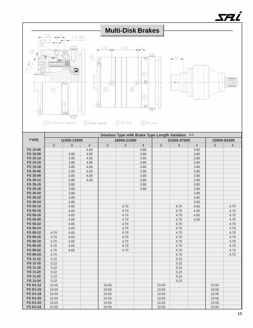
EPYTnoitairaVhtgneLepyTekarBhtiwepyTxobraeG
00031-00011 00012-00081 00073-00013 00016-000352 3 4 2 3 4 2 3 4 3 4
60-51SF 90.4 08.3 08.390-51SF 08.3 90.4 08.3 08.321-51SF 08.3 90.4 08.3 08.351-51SF 08.3 90.4 08.3 08.381-51SF 08.3 90.4 08.3 08.360-53SF 08.3 90.4 08.3 08.390-53SF 08.3 90.4 08.3 08.321-53SF 08.3 90.4 08.3 08.351-53SF 08.3 08.3 08.381-53SF 08.3 08.3 08.302-53SF 08.3 08.322-53SF 08.3 08.342-53SF 08.3 08.321-55SF 56.4 07.4 07.4 56.4 07.451-55SF 56.4 07.4 07.4 56.4 07.481-55SF 56.4 07.4 07.4 56.4 07.402-55SF 56.4 07.4 07.4 56.4 07.422-55SF 56.4 07.4 07.4 07.442-55SF 56.4 07.4 07.4 07.421-58SF 07.4 56.4 07.4 07.4 07.451-58SF 07.4 56.4 07.4 07.4 07.481-58SF 07.4 56.4 07.4 07.4 07.402-58SF 07.4 56.4 07.4 07.4 07.422-58SF 07.4 56.4 07.4 07.4 07.442-58SF 07.4 07.4 07.421-11SF 22.5 22.551-11SF 22.5 22.581-11SF 22.5 22.502-11SF 22.5 22.522-11SF 22.5 22.542-11SF 22.5 22.521-1DSF 55.01 55.01 55.01 55.0151-1DSF 55.01 55.01 55.01 55.0181-1DSF 55.01 55.01 55.01 55.0102-1DSF 55.01 55.01 55.01 55.0122-1DSF 55.01 55.01 55.01 55.0142-1DSF 55.01 55.01 55.01 55.01
Multi-Disk Brakes
L

16
EDOC EPYTROTOM /OVLOVREKRAP D L
1BI 03-21F *41x2x03W 56.1
1CI 04-21F *41x2x03W 90.2
2CI 06-21F *41x2x53W 90.2
1DI 08-21F *61x2x53W 90.2
3BS 91-11F T3123/61 02.2
1BS 82-11F 89.0Ø 02.2
4CS 080/060-11V T4142/21 65.1
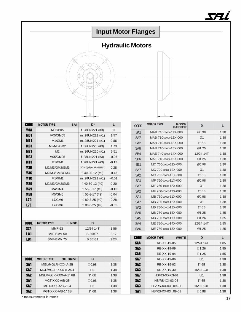
Input Motor Flanges
Hydraulic Motors
* measurements in metric
������������� NNYL-RAHC
NOTAE D L
��� A-EAS005-2...080-2 ∅ 1 83.1
��� A-EAS005-2...080-2 ∅ 52.1 58.1
�� A-EAS005-2...080-2 B6"1 83.1
�� A-EAS005-2...080-2 ∅ 62.1 58.1
��� B-EBS005-2...080-2 T3123/61 02.2
�� B-EBS005-2...080-2 B6"1 02.2
��� B-EBS005-2...080-2 ∅ 1 02.2
���� ��������� SSOFNAD D L
��� PMO ∅ 89.0 83.1
��� PMO ∅ 1 83.1
�� PMO B6"1 83.1
��� PMO ∅ 89.0 83.1
�� PMO ∅ 62.1 58.1
��� PMO ∅ 1 83.1
�� PMO B6"1 83.1
�� PMO ∅ 62.1 58.1
��� PMO T4142/21 58.1
�� PMO ∅ 75.1 13.5
�� PMO T7142/21 13.5
�� PMO ∅ 79.1 36.5
������������� SDNULGGAH
NOSINEDXEBA D L
��� C1M T3123/61 02.2
��� C4M T3123/61 02.2
�� D4M T4142/21 65.1
�� E4M T4142/21 65.1
�� D3M T4142/21 65.1
��� C4M ∅ 78.0 02.2
�� 7M-6M T4142/21 65.1
������������� KITAMORDYH
HTORXER D L
��� 21-01MF2A ∅ 97.0 75.1
�� 61MF2A ∅ 89.0 75.1
��� 21-01MF2A *41x52.1x02W 75.1
�� 61-21-01MF2A *81x52.1x52W 75.1
��� 23-82-32MF2A *41x2x03W 56.1
��� 54MF2A *41x2x03W 90.2
�� 36-65MF2A *61x2x53W 90.2
��� 08MF2A *61x2x53W 90.2
��� 521-701MF2A *12x2x54W 73.4
��� 081-061MF2A *03x2x05W 75.4
��� 002MF2A *03x2x05W 75.4
���� ��������� SREKCIV D L
��� 11A-XXX-N52 T3123/61 02.2
�� X11A-XXX-M54-53 T4142/21 65.1
������������� MAS
KILUARDYH D L
��� 52CN004-05SGA-GA ∅ 89.0 83.1
�� 52SN004-05SGA-GA B6"1 83.1
��� 52CN004-08SRA-RA ∅ 89.0 83.1
�� 52SN004-08SRA-RA B6"1 83.1
17* measurements in metric
���� ��������� IAS *D L
��� 50P/50M )3#(122INU82.f 0
��� 50MG/50M )1#(122INU82.m 75.1
��� 1MG/1M )1#(122INU82.m 68.0
� 2MG/3M/2M )3#(022INU63.f 37.1
�� 2M )1#(022INU63.m 15.3
�� 50MG/50M )3#(122INU82.f 62.0-
�� 1MG/1M )3#(122INU82.f 21.0-
�� 3MG/2MG/3M/2M ����������� �������������� 82.0
�� 3MG/2MG/3M/2M )9#(21-03-04.f 34.0-
��� 1MG/1M )1#(122INU82.m 15.0-
�� 3MG/2MG/3M/2M )9#(21-03-04.f 02.0
� � 4MG/4M )9#(71-3-55.f 61.0-
��� 5MG/5M )9#(71-3-55.f 40.0
��� 6MG/7L )9#(52-3-08.f 82.2
��� 6MG/7L )9#(52-3-08.f 55.0-
���� ��������� EDNIL D L
��� 36FMM T4142/21 65.1
�� 05VMB-FMB 72x03B 71.2
� 57VMB-FMB 13x53B 82.2
���� ��������� EVIRDLIO D L
��� 52-A-XXX-RLGM/LGM ∅ 89.0 83.1
��� 4.52-A-XXX-RLGM/LGM ∅ 1 83.1
��� B6"1-A-XXX-RLGM/LGM B6"1 83.1
��� 52-B/A-XXX-TGM ∅ 89.0 83.1
��� 4.52-B/A-XXX-TGM ∅ 1 83.1
��� B6"1-B/A-XXX-TGM B6"1 83.1
���� ��������� ETIHW D L
��� 50-91-XX-ER T4142/21 58.1
��� 90-91-XX-ER ∅ 62.1 58.1
�� 40-91-XX-ER ∅ 52.1 58.1
�� 60-91-XX-ER ∅ 1 83.1
��� 20-91-XX-ER B6"1 83.1
��� 03-91-XX-ER T3123/61 83.1
�� 10-30-XX-SR/SH ∅ 1 83.1
��� 60-30-XX-SR/SH B6"1 83.1
��� 70-90...30-XX-SR/SH T3123/61 83.1
�� 80-90...30-XX-SR/SH ∅ 89.0 83.1
Input Motor Flanges
Hydraulic Motors
EDOC EPYTROTOM /SSORREKRAP D L
1AS 000-X11-xxxx-017BAM 89.0Ø 83.1
7AS 000-X21-xxxx-017BAM 1Ø 83.1
2AS 000-X31-xxxx-017BAM B6"1 83.1
6AS 000-X51-xxxx-017BAM 52.1Ø 83.1
4BS 000-X41-xxxx-047EAM T4142/21 83.1
6BS 000-X51-xxxx-047EAM 52.1Ø 83.1
1BS 000-X11-xxxx-007CM 89.0Ø 83.1
7AS 000-X21-xxxx-007CM 1Ø 83.1
2AS 000-X31-xxxx-007CM B6"1 83.1
1AS 000-X11-xxxx-067FM 89.0Ø 83.1
7AS 000-X21-xxxx-067FM 1Ø 83.1
2AS 000-X31-xxxx-067FM B6"1 83.1
1AS 000-X11-xxxx-037BM 89.0Ø 83.1
7AS 000-X21-xxxx-037BM 1Ø 83.1
2AS 000-X31-xxxx-037BM B6"1 83.1
6AS 000-X51-xxxx-037BM 52.1Ø 58.1
5AS 000-X71-xxxx-037BM 62.1Ø 58.1
4AS 000-X41-xxxx-087EM T4142/21 58.1
6AS 000-X51-xxxx-087EM 52.1Ø 58.1
18
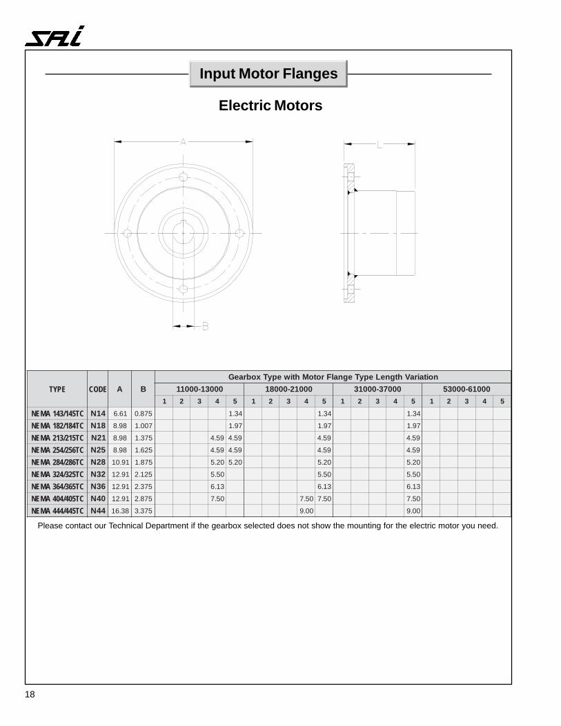
Please contact our Technical Department if the gearbox selected does not show the mounting for the electric motor you need.
Input Motor Flanges
Electric Motors
EPYT EDOC A BnoitairaVhtgneLepyTegnalFrotoMhtiwepyTxobraeG
00031-00011 00012-00081 00073-00013 00016-000351 2 3 4 5 1 2 3 4 5 1 2 3 4 5 1 2 3 4 5
CT541/341AMEN 41N 16.6 578.0 43.1 43.1 43.1
CT481/281AMEN 81N 89.8 700.1 79.1 79.1 79.1
CT512/312AMEN 12N 89.8 573.1 95.4 95.4 95.4 95.4
CT652/452AMEN 52N 89.8 526.1 95.4 95.4 95.4 95.4
CT682/482AMEN 82N 19.01 578.1 02.5 02.5 02.5 02.5
CT523/423AMEN 23N 19.21 521.2 05.5 05.5 05.5
CT563/463AMEN 63N 19.21 573.2 31.6 31.6 31.6
CT504/404AMEN 04N 19.21 578.2 05.7 05.7 05.7 05.7
CT544/444AMEN 44N 83.61 573.3 00.9 00.9
19
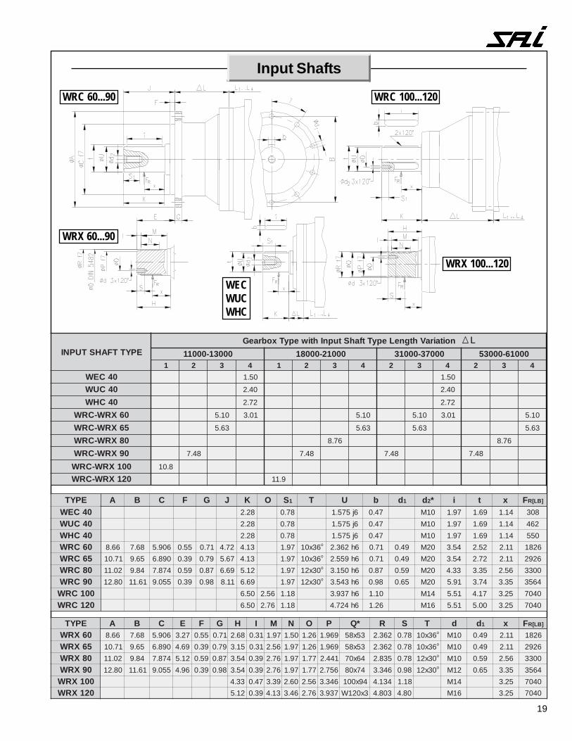
EPYTTFAHSTUPNInoitairaVhtgneLepyTtfahStupnIhtiwepyTxobraeG
00031-00011 00012-00081 00073-00013 00016-000351 2 3 4 1 2 3 4 2 3 4 2 3 4
04CEW 05.1 05.104CUW 04.2 04.2
04CHW 27.2 27.2
06XRW-CRW 01.5 10.3 01.5 01.5 10.3 01.5
56XRW-CRW 36.5 36.5 36.5 36.5
08XRW-CRW 67.8 67.8
09XRW-CRW 84.7 84.7 84.7 84.7
001XRW-CRW 8.01021XRW-CRW 9.11
Input Shafts
L
WRC 60...90
WRX 60...90
WRC 100...120
WRX 100...120
WECWUCWHC
EPYT A B C E F G H I M N O P *Q R S T d d1 x F ]BL[R
06XRW 66.8 86.7 609.5 72.3 55.0 17.0 86.2 13.0 79.1 05.1 62.1 969.1 35x85 263.2 87.0 63x01 o 01M 94.0 11.2 628156XRW 17.01 56.9 098.6 96.4 93.0 97.0 51.3 13.0 65.2 79.1 62.1 969.1 35x85 263.2 87.0 63x01 o 01M 94.0 11.2 629208XRW 20.11 48.9 478.7 21.5 95.0 78.0 45.3 93.0 67.2 79.1 77.1 144.2 46x07 538.2 87.0 03x21 o 01M 95.0 65.2 003309XRW 08.21 16.11 550.9 69.4 93.0 89.0 45.3 93.0 67.2 79.1 77.1 657.2 47x08 643.3 89.0 03x21 o 21M 56.0 53.3 4653001XRW 33.4 74.0 93.3 06.2 65.2 643.3 49x001 431.4 81.1 41M 52.3 0407021XRW 21.5 93.0 31.4 64.3 67.2 739.3 3x021W 308.4 08.4 61M 52.3 0407
EPYT A B C F G J K O S1 T U b d1 d2* i t x F ]BL[R
04CEW 82.2 87.0 6j575.1 74.0 01M 79.1 96.1 41.1 80304CUW 82.2 87.0 6j575.1 74.0 01M 79.1 96.1 41.1 26404CHW 82.2 87.0 6j575.1 74.0 01M 79.1 96.1 41.1 05506CRW 66.8 86.7 609.5 55.0 17.0 27.4 31.4 79.1 63x01 o 6h263.2 17.0 94.0 02M 45.3 25.2 11.2 628156CRW 17.01 56.9 098.6 93.0 97.0 76.5 31.4 79.1 63x01 o 6h955.2 17.0 94.0 02M 45.3 27.2 11.2 629208CRW 20.11 48.9 478.7 95.0 78.0 96.6 21.5 79.1 03x21 o 6h051.3 78.0 95.0 02M 33.4 53.3 65.2 003309CRW 08.21 16.11 550.9 93.0 89.0 11.8 96.6 79.1 03x21 o 6h345.3 89.0 56.0 02M 19.5 47.3 53.3 4653001CRW 05.6 65.2 81.1 6h739.3 01.1 41M 15.5 71.4 52.3 0407021CRW 05.6 67.2 81.1 6h427.4 62.1 61M 15.5 00.5 52.3 0407
20
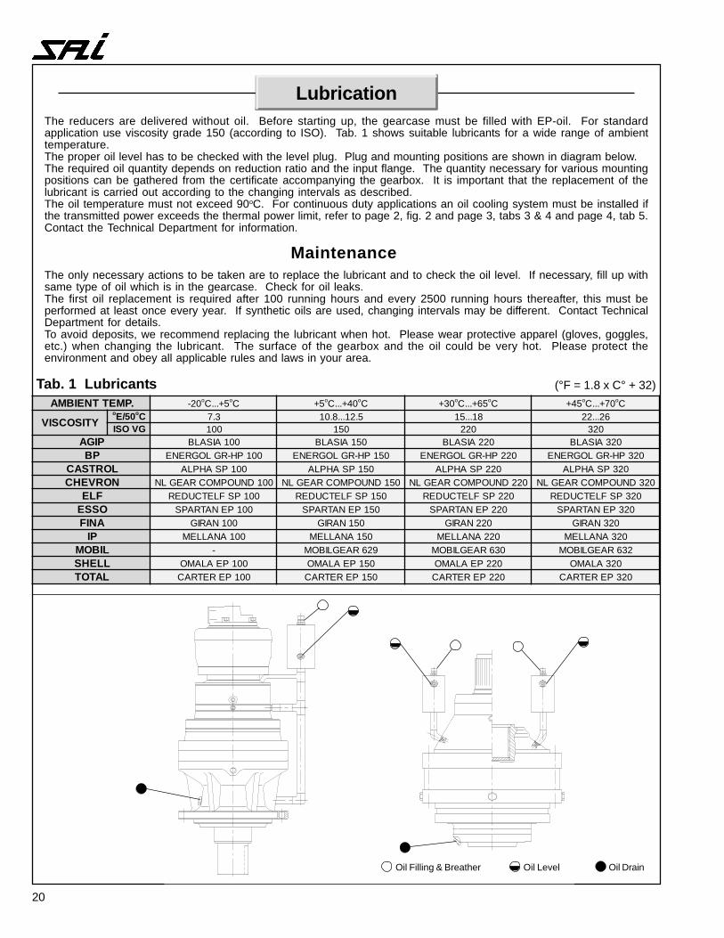
Lubrication
.PMETTNEIBMA 02- o 5+...C oC 5+ o 04+...C oC 03+ o 56+...C oC 54+ o 07+...C oC
YTISOCSIVo 05/E oC 3.7 5.21...8.01 81...51 62...22
GVOSI 001 051 022 023PIGA 001AISALB 051AISALB 022AISALB 023AISALB
PB 001PH-RGLOGRENE 051PH-RGLOGRENE 022PH-RGLOGRENE 023PH-RGLOGRENELORTSAC 001PSAHPLA 051PSAHPLA 022PSAHPLA 023PSAHPLANORVEHC 001DNUOPMOCRAEGLN 051DNUOPMOCRAEGLN 022DNUOPMOCRAEGLN 023DNUOPMOCRAEGLN
FLE 001PSFLETCUDER 051PSFLETCUDER 022PSFLETCUDER 023PSFLETCUDEROSSE 001PENATRAPS 051PENATRAPS 022PENATRAPS 023PENATRAPSANIF 001NARIG 051NARIG 022NARIG 023NARIG
PI 001ANALLEM 051ANALLEM 022ANALLEM 023ANALLEMLIBOM - 926RAEGLIBOM 036RAEGLIBOM 236RAEGLIBOMLLEHS 001PEALAMO 051PEALAMO 022PEALAMO 023ALAMOLATOT 001PERETRAC 051PERETRAC 022PERETRAC 023PERETRAC
Tab. 1 Lubricants
The reducers are delivered without oil. Before starting up, the gearcase must be filled with EP-oil. For standardapplication use viscosity grade 150 (according to ISO). Tab. 1 shows suitable lubricants for a wide range of ambienttemperature.The proper oil level has to be checked with the level plug. Plug and mounting positions are shown in diagram below.The required oil quantity depends on reduction ratio and the input flange. The quantity necessary for various mountingpositions can be gathered from the certificate accompanying the gearbox. It is important that the replacement of thelubricant is carried out according to the changing intervals as described.The oil temperature must not exceed 90oC. For continuous duty applications an oil cooling system must be installed ifthe transmitted power exceeds the thermal power limit, refer to page 2, fig. 2 and page 3, tabs 3 & 4 and page 4, tab 5.Contact the Technical Department for information.
The only necessary actions to be taken are to replace the lubricant and to check the oil level. If necessary, fill up withsame type of oil which is in the gearcase. Check for oil leaks.The first oil replacement is required after 100 running hours and every 2500 running hours thereafter, this must beperformed at least once every year. If synthetic oils are used, changing intervals may be different. Contact TechnicalDepartment for details.To avoid deposits, we recommend replacing the lubricant when hot. Please wear protective apparel (gloves, goggles,etc.) when changing the lubricant. The surface of the gearbox and the oil could be very hot. Please protect theenvironment and obey all applicable rules and laws in your area.
Maintenance
(°F = 1.8 x C° + 32)
Oil Filling & Breather Oil Level Oil Drain
21
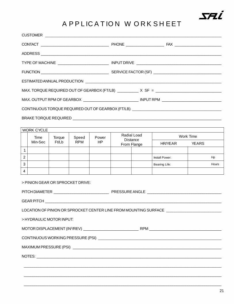
APPLICATION WORKSHEETCUSTOMER ___________________________________________________________________________________
CONTACT ________________________________ PHONE __________________ FAX ______________________
ADDRESS _____________________________________________________________________________________
TYPE OF MACHINE ________________________ INPUT DRIVE ________________________________________
FUNCTION ________________________________ SERVICE FACTOR (SF) ________________________________
ESTIMATED ANNUAL PRODUCTION ________________________________________________________________
MAX. TORQUE REQUIRED OUT OF GEARBOX (FT/LB) __________ X SF = _______________________________
MAX. OUTPUT RPM OF GEARBOX __________________________ INPUT RPM ____________________________
CONTINUOUS TORQUE REQUIRED OUT OF GEARBOX (FT/LB) __________________________________________
BRAKE TORQUE REQUIRED ______________________________________________________________________
> PINION GEAR OR SPROCKET DRIVE:
PITCH DIAMETER __________________________ PRESSURE ANGLE ___________________________________
GEAR PITCH ___________________________________________________________________________________
LOCATION OF PINION OR SPROCKET CENTER LINE FROM MOUNTING SURFACE __________________________
> HYDRAULIC MOTOR INPUT:
MOTOR DISPLACEMENT (IN3/REV) __________________________ RPM __________________________________
CONTINUOUS WORKING PRESSURE (PSI) __________________________________________________________
MAXIMUM PRESSURE (PSI) ______________________________________________________________________
NOTES: _______________________________________________________________________________________
_____________________________________________________________________________________________
_____________________________________________________________________________________________
_____________________________________________________________________________________________
ELCYCKROW
emiTceS-niM
euqroTbL/tF
deepSMPR
rewoPPH
daoLlaidaRecnatsiD
egnalFmorF
emiTkroW
SRAEYRAEY/RH
1
2 :rewoPllatsnI pH
3 :efiLgniraeB sruoH
4