Embed Size (px)
Citation preview
a
115rpee | Série III | n.º 11 | novembro de 2019
Seismic analysis of an ultra-high arch dam using the 3DFE program DamDySSA3.0.
Study on the influence of the reservoir water level
Análise sísmica de uma barragem abóbada ultra-alta utilizando o programa de EF3D DamDySSA3.0. Estudo da influência do nível da água na albufeira
André AlegreSérgio Oliveira
Margarida EspadaRomano Câmara
AbstractThe seismic response of a 290 m high arch dam, located in a high seismicity zone in China, is studied in this paper. The goal is to evaluate the influence of the reservoir water level on the dam’s seismic behaviour.
The numerical simulations are carried out using the 3DFE program DamDySSA3.0, developed in LNEC for linear dynamic analysis of dams, including a module for seismic analysis under applied base accelerations. The problem is solved by a Finite Element coupled formulation in displacements and pressures. The seismic response is computed in time domain for the dam-reservoir-foundation system using the Newmark method.
The seismic study is performed for two reservoir levels, considering 5% damping. A set of seismic accelerograms recorded in the Jiashi station (peak acceleration of 0.23 g) was used as input. Displacement and acceleration time histories, stress fields and the hoop and cantilever stress envelopes at the central section are presented.
ResumoNeste artigo analisa-se a resposta sísmica de uma barragem abóbada com 290 m de altura, localizada numa zona de elevada sismicidade na China. O objetivo é estudar a influência do nível da água da albufeira no comportamento sísmico da obra.
As simulações numéricas são efetuadas com o programa de EF3D DamDySSA3.0, desenvolvido no LNEC para análise dinâmica linear de barragens, incluindo um módulo para análise sísmica sob acelerações aplicadas na base. O problema é resolvido utilizando uma formulação de Elementos Finitos em deslocamentos e pressões. A resposta sísmica calcula-se no domínio do tempo para o sistema barragem-fundação-albufeira com o método de Newmark.
O estudo sísmico realiza-se para duas cotas de água, considerando 5% de amortecimento e como input um conjunto de acelerogramas medidos em Jiashi, China (aceleração de pico de 0,23 g). Apresentam-se histórias de deslocamentos e acelerações, campos de tensões e envolventes de tensões segundo os arcos e as consolas na secção central.
Keywords: Seismic analysis of arch dams / Influence of the reservoir water level // 3DFE program / Coupled formulation in displacements and pressures
Palavras-chave: Análise sísmica de barragens abóbada / Influência do nível da água // Programa de EF3D / Formulação acoplada em deslocamentos e pressões
116
Seismic analysis of an ultra-high arch dam using the 3DFE program DamDySSA3.0. Study on the influence of the reservoir water levelAndré Alegre, Sérgio Oliveira, Margarida Espada, Romano Câmara
rpee | Série III | n.º 11 | novembro de 2019
Aviso legal
As opiniões manifestadas na Revista Portuguesa de Engenharia de Estruturas são da exclusiva responsabilidade dos seus autores.
Legal notice
The views expressed in the Portuguese Journal of Structural Engineering are the sole responsibility of the authors.
ALEGRE, A. [et al.] – Seismic analysis of an ultra-high arch dam using the 3DFE program DamDySSA3.0. Study on the influence of the reservoir water level. Revista Portuguesa de Engenharia de Estruturas. Ed. LNEC. Série III. n.º 11. ISSN 2183-8488. (novembro 2019) 115-126.
André Alegre
PhD StudentLaboratório Nacional de Engenharia Civil (LNEC) / Instituto Superior Técnico (IST-ULisboa)Lisboa, [email protected]
Sérgio Oliveira
Assistant ResearcherLaboratório Nacional de Engenharia Civil (LNEC)Lisboa, [email protected]
Margarida Espada
Junior Research FellowLaboratório Nacional de Engenharia Civil (LNEC)Lisboa, [email protected]
Romano Câmara
Principal ResearcherLaboratório Nacional de Engenharia Civil (LNEC)Lisboa, [email protected]
1 IntroductionLarge and ultra-high arch dams are civil engineering structures of great relevance for populations and with high potential risk [1]. This is a significant matter, considering that many of them are located in seismic zones all over the world, as is the case for several of the new ultra-high dams in China. Therefore, it is of the utmost importance to improve our knowledge about the seismic behaviour of these structures. This goal can be achieved based on monitoring data from Seismic and Structural Health Monitoring (SSHM) systems, installed in dams for continuously monitoring their dynamic response over time, under environmental/operational vibrations and during seismic events. With that aim, Seismic and Structural Health Monitoring (SSHM) systems have been installed in several large dams [2] and are being proposed for both older and more recent dams, to control the evolution of modal parameters over time [3,4,5] and to characterize the structural response under seismic vibrations [4,6,7].
Seeking to contribute to a better understanding of the seismic behaviour of dams, the investment in SSHM systems should be complemented with the development of new numerical models for simulating the seismic response as accurately as possible for various case scenarios. Provided they are properly calibrated and validated based on experimental results, numerical models are of great use for increasing knowledge about the dynamic response of dams during seismic events and for supporting seismic safety studies.
The numerical modelling of the dynamic behaviour of the dam-reservoir-foundation system is a research field that has been widely studied over the last decades, resulting in the development of various well-established formulations based on the Finite Element Method (FEM) [8]. Still, given the complexity of the problem, important challenges continue to arise, namely concerning the dynamic water-dam interaction, the hydrodynamic reservoir behaviour, the influence of water level variations, the foundation’s dynamic behaviour, the dam-foundation interaction, the seismic input modelling and the global system damping.
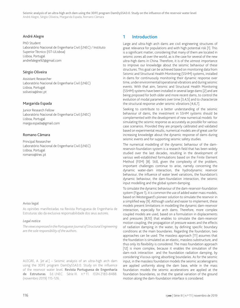
To simulate the dynamic behaviour of the dam-reservoir-foundation system (Figure 1), it is common the use of added water mass models, based on Westergaard’s pioneer solution to simulate the reservoir in a simplified way [9]. Although useful and easier to implement, these models present limitations in modelling the dynamic dam-reservoir interaction, especially for arch dams. Therefore, more complex coupled models are used, based on a formulation in displacements and pressures [8,10] that enables to simulate the dam-reservoir motion coupling, the propagation of pressure waves and the effects of radiation damping in the water, by defining specific boundary conditions at the main boundaries. Regarding the foundation, two approaches can be used. The massless approach [11] assumes that the foundation is simulated as an elastic, massless substructure, and thus only its flexibility is considered. The mass foundation approach [12] is more complex, because it enables the simulation of the dam-rock interaction and the foundation radiation damping, by considering Viscous-spring absorbing boundaries. As for the seismic input, in the massless foundation models the seismic accelerograms are applied uniformly along the dam base, while in the mass foundation models the seismic accelerations are applied at the foundation boundaries, so that the spatial variation of the ground motion along the dam-foundation interface is considered.
117
Seismic analysis of an ultra-high arch dam using the 3DFE program DamDySSA3.0. Study on the influence of the reservoir water levelAndré Alegre, Sérgio Oliveira, Margarida Espada, Romano Câmara
rpee | Série III | n.º 11 | novembro de 2019
For structural analysis of dams, under static and/or seismic loads, it is usual to assume the full reservoir condition given that it results in higher water pressures at the upstream face of the dam and consequently in greater displacements and stresses. However, the oscillatory movements of greater amplitude under seismic ground motion can occur for non-full reservoir conditions, as shown in [13], because the seismic response is influenced by the dynamic dam-water interaction and it also depends on the relation between the natural frequencies of the dam-reservoir-foundation system and the frequency content of the seismic accelerograms.
2 DamDySSA3D1.0: a program for linear dynamic analysis of arch dams
The numerical calculations presented in this paper were carried out with the 3DFE program DamDySSA3.0, which was developed in LNEC and optimized for linear dynamic analysis of concrete dams, including a module for seismic analysis. The hypothesis of isotropic materials with linear elastic behaviour is assumed, for the continuum and eventually at joints or cracks existing in the dam and the foundation. For the solid domain the hypothesis of proportional (Rayleigh) or non-proportional damping can be assumed, while in the fluid domain the damping effect is associated with radiation energy loss. The dam-reservoir-foundation system is simulated based on a coupled model, using a FEM formulation in displacements and pressures, and considering the massless foundation approach. The seismic response is calculated for the coupled system by direct time integration in global coordinates using the Newmark method. The calculations can be performed for several dynamic load combinations, including a) the self-weight (SW) of the dam, assuming the body load to be applied simultaneously, b) the hydrostatic pressure (HP) at the upstream face, and c) the seismic load, considering the seismic accelerograms to be applied at the base and uniformly distributed along the dam-rock interface.
2.1 Coupled problem in displacements and pressures
The dynamic coupled problem (Figure 2) for the dam-reservoir-foundation system is defined by a Boundary Values Problem (BVP), including the governing differential equations for the solid ΩS and the fluid ΩW domains and the respective boundary conditions, Equation 1.
The coupled problem’s unknowns, to be calculated in time domain, are the displacement vector 1 2 3(x ,x ,x ,t)u u=
on a point PS in the solid domain and the hydrodynamic pressure 1 2 3(x ,x ,x ,t)p p= on a point Pw in the fluid domain.
In the equation for the solid domain, L is a differential operator for the displacement-strain relation, D is the elasticity matrix (stress--strain relation), and 1 2 3(x ,x ,x ,t) ( )s s S scuf gf uaρ ρ= − + −=
(kN/m3) is the vector of body forces, which includes the gravity, inertia and damping components, respectively - u
and u
are the velocity and acceleration vectors, sρ (kg/m3) is the mass density of the solid material, g (m/s2), is the gravity acceleration vector, cs (kN.s/m/m3) is the specific material damping (kN.s/m/m3), and finally 1 2 3(x ,x ,x ,t)S Sa a=
(m/s2) is the applied seismic acceleration vector at the dam base. For the wave equation (2), the speed of sound in water (m/s) is w w wc K ρ= (m/s), where Kw is the bulk modulus (GPa) and wρ is the water density (kg/m3).
Regarding the boundary conditions, the displacement boundary conditions u u=
are defined by introducing null displacement values at the foundation bottom boundary fΓ ; the traction boundary conditions t t=
are incorporated by applying the hydrostatic pressures at the upstream face of the dam (dam-water interface 1Γ ). The boundary conditions for the reservoir are defined as in [8]: a) the solid-water motion coupling is defined at the dam-reservoir interface 1Γ , b) only horizontal motion exists at the reservoir bottom 2Γ , c) the free surface 3Γ has null pressure, and d) only outgoing pressure waves are considering, by means of a radiation boundary at the end of the reservoir (water-water interface
4Γ ). The normal vector to any surface iΓ is represented by i
nΓ
.
Figure 1 3DFE models of the dam-reservoir-foundation system for dynamic analysis of arch dams. Different reservoir water levels

118
Seismic analysis of an ultra-high arch dam using the 3DFE program DamDySSA3.0. Study on the influence of the reservoir water levelAndré Alegre, Sérgio Oliveira, Margarida Espada, Romano Câmara
rpee | Série III | n.º 11 | novembro de 2019
Figure 2 Coupled model. Solid and fluid domains and main boundaries
2.2 Discrete system. Finite element formulation
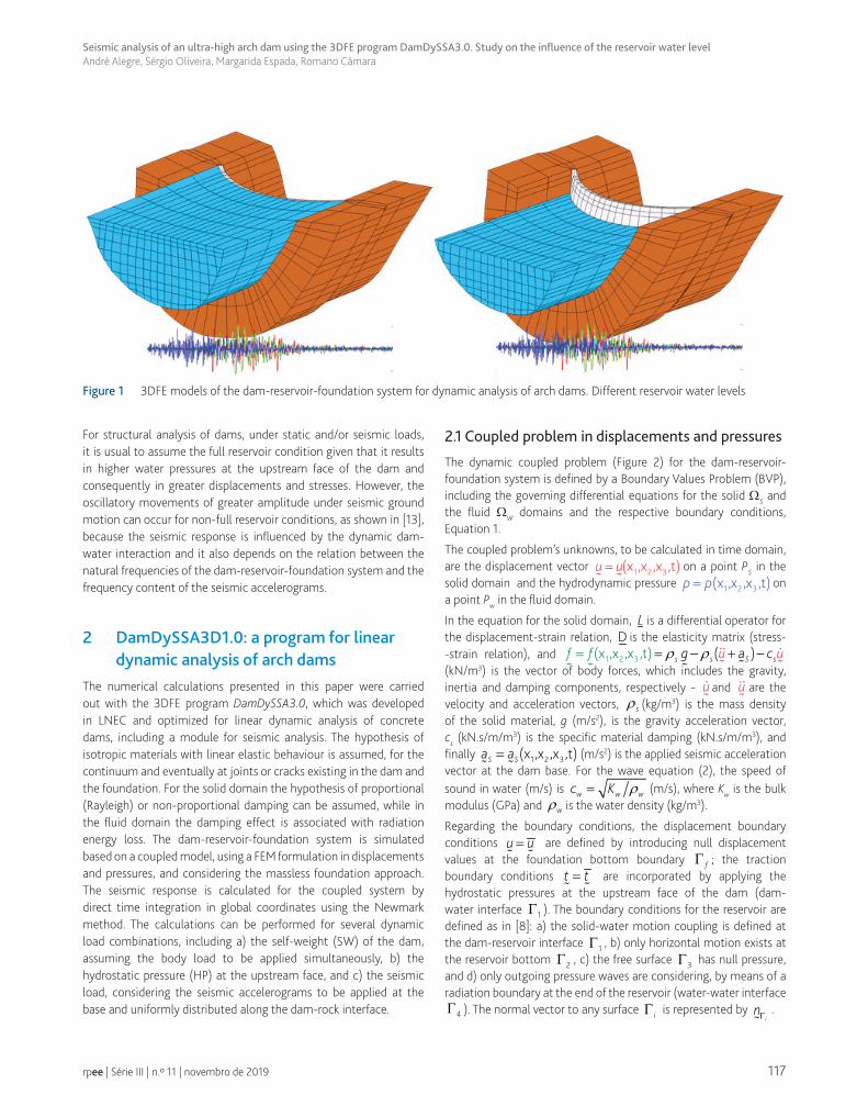
To solve the coupled problem, the system is discretized (Figure 3) using displacement finite elements (FE) for the dam and the foundation (solid domain) and pressure FE for the reservoir (fluid domain). The nodes within the solid domain have three displacement degrees of freedom, while the nodal points in the fluid domain have only one, the hydrodynamic pressure. In DamDySSA3.0, the FE mesh is achieved using 3D isoparametric elements with 20 nodes. Considering the massless foundation approach (the foundation stiffness is considered using a sub-structuration technique), the dynamic calculations are performed only for the dam-reservoir system.
Using a FEM formulation in displacements and pressures, based on a standard Galerkin procedure, the solution is approximated as
eNu uu =
for the displacements in a point Ps in the dam, and as eNpp p=
for the pressures in a point Pw within the reservoir, where eu
and ep
are the corresponding nodal parameters, while Nu and
Np are the matrices containing the appropriate approximation functions.
The discretized form of the presented coupled problem is obtained by introducing the above approximations into the weak form of the governing differential equations and considering the outlined boundary conditions, using the Gauss integration method. Finally, the solid and fluid dynamic equations of motion for the discrete system are established in coupled matrix form:
s
ww
F
F
− + + =
T p
u u u
p p
m 0 c 0 k Q
0 R 0 HQ S
ρ (2)
where m , c and k denote the mass, damping and stiffness matrices for the solid domain, S , R and H are the corresponding terms for the water domain and Q is the coupling matrix to simulate the dynamic dam-water [8,10]. The force vectors are obtained as (t) m (t)s s SF F s a= = −
for the solid domain and asT(t) Q (t)w w w SF F s aρ= = −
for the fluid domain, resulting from the seismic acceleration time histories applied at the base Sa
[19]( s is a matrix used to obtain the corresponding nodal forces in the upstream-downstream, cross-valley and vertical directions).
The discrete coupled problem can be presented in its final, simple form as
F+ + =M q C q K q
(3)
where M , K and C are the global mass, damping and stiffness matrices for the whole coupled system, and
= =
q q(t)
p
u
(4)
is the global coupled unknowns, which includes the problem’s unknowns: the displacement vector u u(t)=
and the hydrodynamic pressures vector p p(t)=
.
(1)
( )
2
1
1
4
T1 2 3
21 2 32
T2
,T 3T
1, 1
4
D 0, ( , , )
0, ( , , )
0 ,,0, ( )
; ; 0 , , , ( )
1,
w
s s
w w
S bs s u f
ww w s s t
w
L L f P x x x
P x x xc
nau P
nt n h P
u
uu
u
pp
p p
pn
cp
n
ργ Γ
Γ
ΓΓ
Γ
+ = ∀ ∈Ω∇ − = ∀ ∈ Ω
Γ= Γ = ∀ ∈ Γ = Γ ∂ = Γ = − Γ= ∀ ∈ Γ = Γ ∂ ∂ = − Γ
=
∂
119
Seismic analysis of an ultra-high arch dam using the 3DFE program DamDySSA3.0. Study on the influence of the reservoir water levelAndré Alegre, Sérgio Oliveira, Margarida Espada, Romano Câmara
rpee | Série III | n.º 11 | novembro de 2019
Figure 3 Coupled system: discretized form. Type of FE used in DamDySSA3.0
2.3 Seismic response calculation
In DamDySSA3.0, the forced vibration response is calculated by numerical integration using a time-stepping procedure based on the Newmark method, in order to approximate the solution for the dynamic coupled problem in time domain (Figure 4). The aim is to solve the governing dynamic equation at each time step t + Δt
t+ t t+ t t+ t t+ tM q C q K q F∆ ∆ ∆ ∆+ + =
(5)
In the Newmark formulation [13], considering a time step Δt, the solutions for the displacements and velocities at time t + Δt are obtained from Taylor Series expansions, while the accelerations are assumed to have a constant or linear variation within each time step. For the coupled problem, the global coupled unknowns and the respective first time derivatives at time t + Δt can be written in the same manner,
2 2t+ t t t t t+ t
1q q t q t q t q
2β β∆ ∆
= + ∆ ⋅ + ∆ ⋅ − ⋅ + ∆ ⋅ ⋅
(6)
t+ t t t t+ tq q t (1 ) q t qγ γ∆ ∆= + ∆ ⋅ − ⋅ + ∆ ⋅ ⋅
(7)
where β and γ are parameters introduced by Newmark to reflect the influence of the second time derivatives in the solutions for t+ tq ∆
and t+ tq ∆
at time t + Δt, respectively. Using λ = 1/2 and β = 1/4 means that the constant acceleration hypothesis is regarded and the method is unconditionally stable.
Considering the above relations, the governing equation of the coupled system at each t + Δt is expressed only in terms of the coupled unknowns t+ tq ∆
( ) ( ) ( )0 1 t+ t t+ t 0 t 2 tt 3 t 1 t 4 t 5 tM C K q M q q q C q q qFα α α α α α α α∆ ∆⋅ + ⋅ + ⋅ = + ⋅ ⋅ + ⋅ + ⋅ + ⋅ ⋅ + ⋅ + ⋅
(8)
with the integration constants
( )
0 1 2 32
4 5 6 7
1 1 1; ; ; 1
t t t 2
t1 ; 2 ; 1 t ; t
2
γα α α αβ β β β
γ γα α α γ α γβ β
= = = = −∆ ∆ ∆
∆= − = ⋅ − = − ⋅∆ = ⋅∆
(9)
Finally, the seismic response of the dam-reservoir-foundation system is calculated by solving the equivalent equation below at each time step,
* *t+ t t+ tS q F∆ ∆⋅ =
(10)
120
Seismic analysis of an ultra-high arch dam using the 3DFE program DamDySSA3.0. Study on the influence of the reservoir water levelAndré Alegre, Sérgio Oliveira, Margarida Espada, Romano Câmara
rpee | Série III | n.º 11 | novembro de 2019
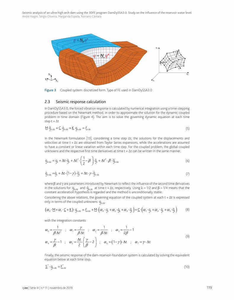
Figure 4 Discrete coupled problem. Dynamic response: displacements and pressures
2.4 Developed graphical user interface
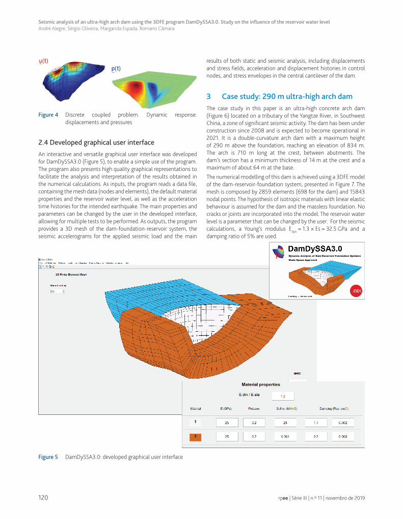
An interactive and versatile graphical user interface was developed for DamDySSA3.0 (Figure 5), to enable a simple use of the program. The program also presents high quality graphical representations to facilitate the analysis and interpretation of the results obtained in the numerical calculations. As inputs, the program reads a data file, containing the mesh data (nodes and elements), the default material properties and the reservoir water level, as well as the acceleration time histories for the intended earthquake. The main properties and parameters can be changed by the user in the developed interface, allowing for multiple tests to be performed. As outputs, the program provides a 3D mesh of the dam-foundation-reservoir system, the seismic accelerograms for the applied seismic load and the main
results of both static and seismic analysis, including displacements and stress fields, acceleration and displacement histories in control nodes, and stress envelopes in the central cantilever of the dam.
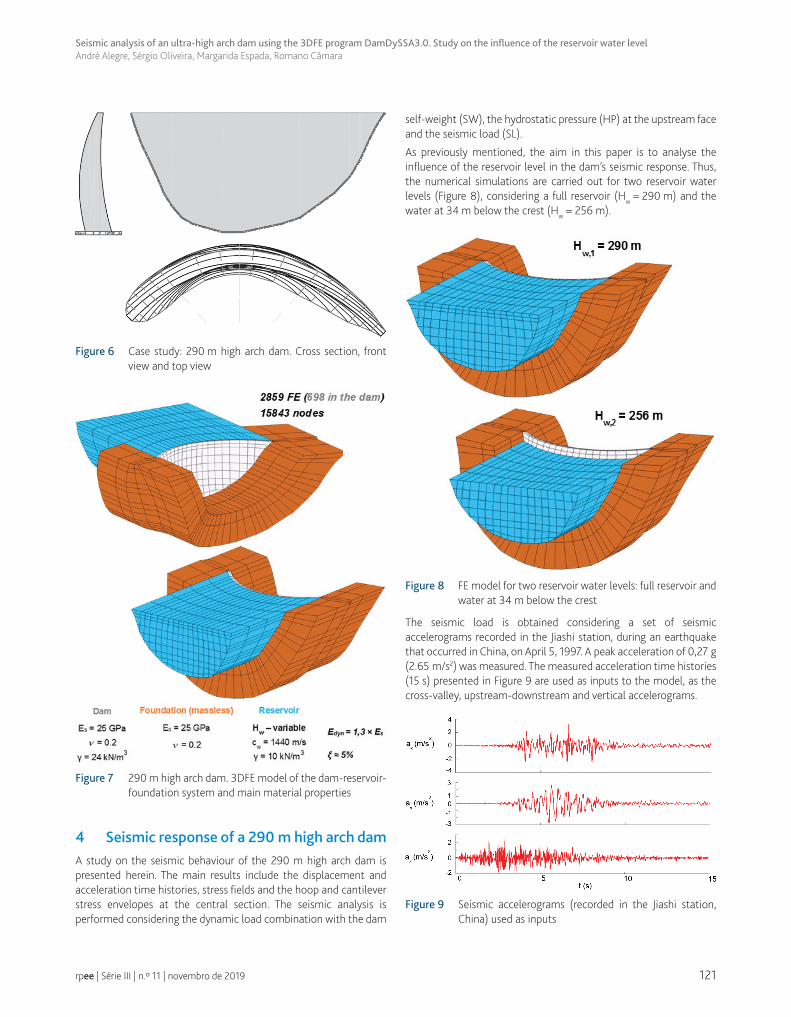
3 Case study: 290 m ultra-high arch damThe case study in this paper is an ultra-high concrete arch dam (Figure 6) located on a tributary of the Yangtze River, in Southwest China, a zone of significant seismic activity. The dam has been under construction since 2008 and is expected to become operational in 2021. It is a double-curvature arch dam with a maximum height of 290 m above the foundation, reaching an elevation of 834 m. The arch is 710 m long at the crest, between abutments. The dam’s section has a minimum thickness of 14 m at the crest and a maximum of about 64 m at the base.
The numerical modelling of this dam is achieved using a 3DFE model of the dam-reservoir-foundation system, presented in Figure 7. The mesh is composed by 2859 elements (698 for the dam) and 15843 nodal points. The hypothesis of isotropic materials with linear elastic behaviour is assumed for the dam and the massless foundation. No cracks or joints are incorporated into the model. The reservoir water level is a parameter that can be changed by the user. For the seismic calculations, a Young’s modulus Edyn = 1.3 × Es = 32.5 GPa and a damping ratio of 5% are used.
Figure 5 DamDySSA3.0: developed graphical user interface
121
Seismic analysis of an ultra-high arch dam using the 3DFE program DamDySSA3.0. Study on the influence of the reservoir water levelAndré Alegre, Sérgio Oliveira, Margarida Espada, Romano Câmara
rpee | Série III | n.º 11 | novembro de 2019
Figure 6 Case study: 290 m high arch dam. Cross section, front view and top view
Figure 7 290 m high arch dam. 3DFE model of the dam-reservoir-foundation system and main material properties
4 Seismic response of a 290 m high arch damA study on the seismic behaviour of the 290 m high arch dam is presented herein. The main results include the displacement and acceleration time histories, stress fields and the hoop and cantilever stress envelopes at the central section. The seismic analysis is performed considering the dynamic load combination with the dam
self-weight (SW), the hydrostatic pressure (HP) at the upstream face and the seismic load (SL).
As previously mentioned, the aim in this paper is to analyse the influence of the reservoir level in the dam’s seismic response. Thus, the numerical simulations are carried out for two reservoir water levels (Figure 8), considering a full reservoir (Hw = 290 m) and the water at 34 m below the crest (Hw = 256 m).
Figure 8 FE model for two reservoir water levels: full reservoir and water at 34 m below the crest
The seismic load is obtained considering a set of seismic accelerograms recorded in the Jiashi station, during an earthquake that occurred in China, on April 5, 1997. A peak acceleration of 0,27 g (2.65 m/s2) was measured. The measured acceleration time histories (15 s) presented in Figure 9 are used as inputs to the model, as the cross-valley, upstream-downstream and vertical accelerograms.
Figure 9 Seismic accelerograms (recorded in the Jiashi station, China) used as inputs
122
Seismic analysis of an ultra-high arch dam using the 3DFE program DamDySSA3.0. Study on the influence of the reservoir water levelAndré Alegre, Sérgio Oliveira, Margarida Espada, Romano Câmara
rpee | Série III | n.º 11 | novembro de 2019
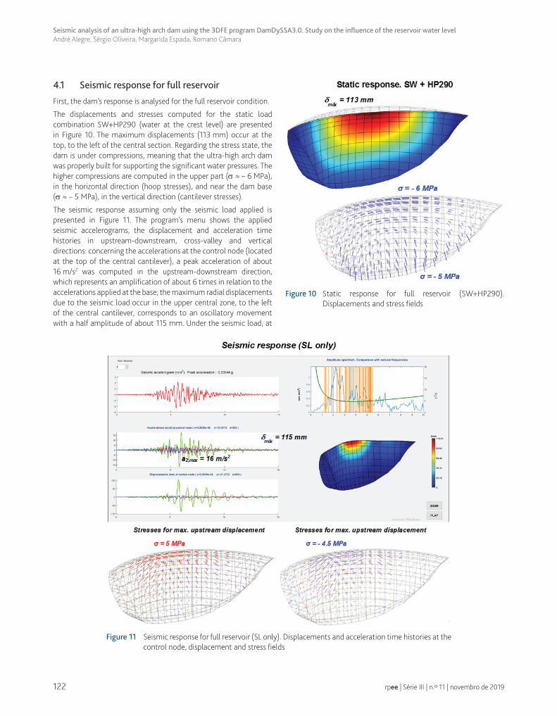
4.1 Seismic response for full reservoir
First, the dam’s response is analysed for the full reservoir condition.
The displacements and stresses computed for the static load combination SW+HP290 (water at the crest level) are presented in Figure 10. The maximum displacements (113 mm) occur at the top, to the left of the central section. Regarding the stress state, the dam is under compressions, meaning that the ultra-high arch dam was properly built for supporting the significant water pressures. The higher compressions are computed in the upper part (σ ≈ – 6 MPa), in the horizontal direction (hoop stresses), and near the dam base (σ ≈ – 5 MPa), in the vertical direction (cantilever stresses).
The seismic response assuming only the seismic load applied is presented in Figure 11. The program’s menu shows the applied seismic accelerograms, the displacement and acceleration time histories in upstream-downstream, cross-valley and vertical directions: concerning the accelerations at the control node (located at the top of the central cantilever), a peak acceleration of about 16 m/s2 was computed in the upstream-downstream direction, which represents an amplification of about 6 times in relation to the accelerations applied at the base; the maximum radial displacements due to the seismic load occur in the upper central zone, to the left of the central cantilever, corresponds to an oscillatory movement with a half amplitude of about 115 mm. Under the seismic load, at
Figure 11 Seismic response for full reservoir (SL only). Displacements and acceleration time histories at the control node, displacement and stress fields
Figure 10 Static response for full reservoir (SW+HP290). Displacements and stress fields
123
Seismic analysis of an ultra-high arch dam using the 3DFE program DamDySSA3.0. Study on the influence of the reservoir water levelAndré Alegre, Sérgio Oliveira, Margarida Espada, Romano Câmara
rpee | Série III | n.º 11 | novembro de 2019
the time instant of maximum downstream displacement, the arches become compressed: the resulting deformation originates high horizontal compressions (σ ≈ – 4.6 MPa) in the upper part of the dam (upstream face). When the maximum upstream displacements occur, the arches tend to open (decompress): high horizontal tensile stresses (σ ≈ – 5.3 MPa) arise near the top of the central zone, which will reduce the compressions along the arches cause by the static load combination SW+HP.
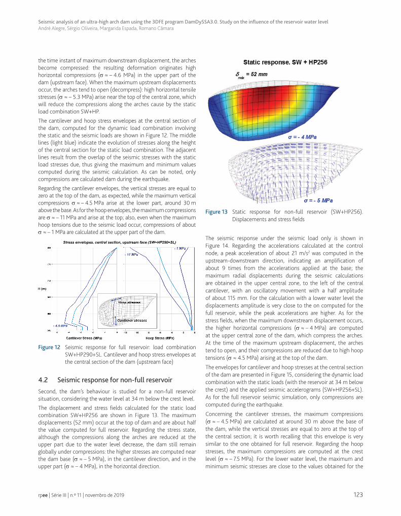
The cantilever and hoop stress envelopes at the central section of the dam, computed for the dynamic load combination involving the static and the seismic loads are shown in Figure 12. The middle lines (light blue) indicate the evolution of stresses along the height of the central section for the static load combination. The adjacent lines result from the overlap of the seismic stresses with the static load stresses due, thus giving the maximum and minimum values computed during the seismic calculation. As can be noted, only compressions are calculated dam during the earthquake.
Regarding the cantilever envelopes, the vertical stresses are equal to zero at the top of the dam, as expected, while the maximum vertical compressions σ ≈ – 4.5 MPa arise at the lower part, around 30 m above the base. As for the hoop envelopes, the maximum compressions are σ ≈ – 11 MPa and arise at the top; also, even when the maximum hoop tensions due to the seismic load occur, compressions of about σ ≈ – 1 MPa are calculated at the upper part of the dam.
Figure 12 Seismic response for full reservoir: load combination SW+HP290+SL. Cantilever and hoop stress envelopes at the central section of the dam (upstream face)
4.2 Seismic response for non-full reservoir
Second, the dam’s behaviour is studied for a non-full reservoir situation, considering the water level at 34 m below the crest level.
The displacement and stress fields calculated for the static load combination SW+HP256 are shown in Figure 13. The maximum displacements (52 mm) occur at the top of dam and are about half the value computed for full reservoir. Regarding the stress state, although the compressions along the arches are reduced at the upper part due to the water level decrease, the dam still remain globally under compressions: the higher stresses are computed near the dam base (σ ≈ – 5 MPa), in the cantilever direction, and in the upper part (σ ≈ – 4 MPa), in the horizontal direction.
Figure 13 Static response for non-full reservoir (SW+HP256). Displacements and stress fields
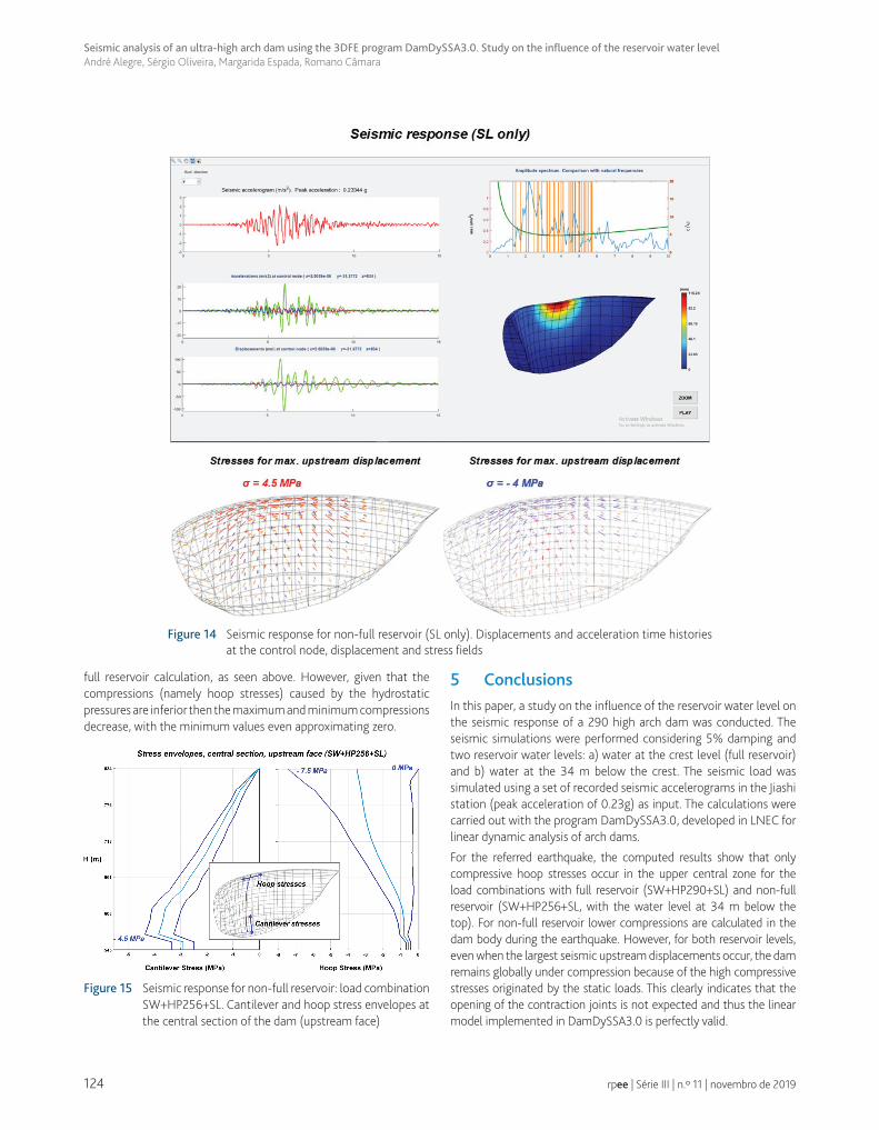
The seismic response under the seismic load only is shown in Figure 14. Regarding the accelerations calculated at the control node, a peak acceleration of about 21 m/s2 was computed in the upstream-downstream direction, indicating an amplification of about 9 times from the accelerations applied at the base; the maximum radial displacements during the seismic calculations are obtained in the upper central zone, to the left of the central cantilever, with an oscillatory movement with a half amplitude of about 115 mm. For the calculation with a lower water level the displacements amplitude is very close to the on computed for the full reservoir, while the peak accelerations are higher. As for the stress fields, when the maximum downstream displacement occurs, the higher horizontal compressions (σ ≈ – 4 MPa) are computed at the upper central zone of the dam, which compress the arches. At the time of the maximum upstream displacement, the arches tend to open, and their compressions are reduced due to high hoop tensions (σ ≈ 4.5 MPa) arising at the top of the dam.
The envelopes for cantilever and hoop stresses at the central section of the dam are presented in Figure 15, considering the dynamic load combination with the static loads (with the reservoir at 34 m below the crest) and the applied seismic accelerograms (SW+HP256+SL). As for the full reservoir seismic simulation, only compressions are computed during the earthquake.
Concerning the cantilever stresses, the maximum compressions (σ ≈ – 4.5 MPa) are calculated at around 30 m above the base of the dam, while the vertical stresses are equal to zero at the top of the central section; it is worth recalling that this envelope is very similar to the one obtained for full reservoir. Regarding the hoop stresses, the maximum compressions are computed at the crest level (σ ≈ – 7.5 MPa). For the lower water level, the maximum and minimum seismic stresses are close to the values obtained for the
124
Seismic analysis of an ultra-high arch dam using the 3DFE program DamDySSA3.0. Study on the influence of the reservoir water levelAndré Alegre, Sérgio Oliveira, Margarida Espada, Romano Câmara
rpee | Série III | n.º 11 | novembro de 2019
full reservoir calculation, as seen above. However, given that the compressions (namely hoop stresses) caused by the hydrostatic pressures are inferior then the maximum and minimum compressions decrease, with the minimum values even approximating zero.
Figure 15 Seismic response for non-full reservoir: load combination SW+HP256+SL. Cantilever and hoop stress envelopes at the central section of the dam (upstream face)
5 ConclusionsIn this paper, a study on the influence of the reservoir water level on the seismic response of a 290 high arch dam was conducted. The seismic simulations were performed considering 5% damping and two reservoir water levels: a) water at the crest level (full reservoir) and b) water at the 34 m below the crest. The seismic load was simulated using a set of recorded seismic accelerograms in the Jiashi station (peak acceleration of 0.23g) as input. The calculations were carried out with the program DamDySSA3.0, developed in LNEC for linear dynamic analysis of arch dams.
For the referred earthquake, the computed results show that only compressive hoop stresses occur in the upper central zone for the load combinations with full reservoir (SW+HP290+SL) and non-full reservoir (SW+HP256+SL, with the water level at 34 m below the top). For non-full reservoir lower compressions are calculated in the dam body during the earthquake. However, for both reservoir levels, even when the largest seismic upstream displacements occur, the dam remains globally under compression because of the high compressive stresses originated by the static loads. This clearly indicates that the opening of the contraction joints is not expected and thus the linear model implemented in DamDySSA3.0 is perfectly valid.
Figure 14 Seismic response for non-full reservoir (SL only). Displacements and acceleration time histories at the control node, displacement and stress fields
125
Seismic analysis of an ultra-high arch dam using the 3DFE program DamDySSA3.0. Study on the influence of the reservoir water levelAndré Alegre, Sérgio Oliveira, Margarida Espada, Romano Câmara
rpee | Série III | n.º 11 | novembro de 2019
If stronger earthquakes were to be considered, important hoop tensions could arise in the referred zones, particularly for lower water levels. This leads to two important remarks: i) the full reservoir condition may not be the most disadvantageous situation from the structural safety point of view; and ii) with a linear model, significant hoop tensions are computed at the zones where the contraction joints tend to open in real dams (in that case, to simulate the joints’ opening/closing behaviour a non-linear model with joints would be required).
In conclusion, this study has shown that the seismic response of dams is clearly influenced by the water level in the reservoir. Of course, it is important to remind that it also depends on the frequency content of the seismic accelerograms. Regarding the developed program, provided that a linear analysis is appropriate, DamDySSA3.0 has proven to be a reliable tool to simulate and thus predict the seismic behaviour of arch dams, even for considerable seismic events.
AcknowledgmentsThe authors wish to acknowledge the funding association, Fundação para a Ciência e Tecnologia, Portugal (FCT) for the PhD grant SFRH/BD/116417/2016.
References
[1] Regulamento de Segurança de Barragens. Decreto-Lei Nº 21/2018 de 20 de março, 2018.
[2] Oliveira, S.; Alegre, A. – "Seismic and structural health monitoring of dams in Portugal" in Seismic Structural Health Monitoring - From Theory to Successful Applications. Ed. by M.P. Limongelli and M. Celebi, Springer, 2019, chapter 4.
[3] Olivera et al. – "’Long-term dynamic monitoring of arch dams. The case of Cabril dam, Portugal". 15th World Congress on Earthquake Engineering, Lisbon, Portugal, 2012.
[4] Oliveira, S.; Alegre, A. – "Seismic and structural health monitoring of Cabril dam". 3rd Meeting of EWG Dams and Earthquakes, an International Symposium. LNEC, Lisbon, Portugal, 2019.
[5] Bukenya, P.; Moyo, P. – "Monitoring the structural behaviour of concrete arch dams: the case of Roode Elsberg dam, South Africa". SANCOLD Conference on Management of Dams and Reservoirs in Southern Africa. Centurion, Thswane, South Africa, 2017.
[6] Chopra, A. K.; Wang, J. – "Comparison of recorded and computed earthquake response of arch dams". 15th World Congress on Earthquake Engineering, Lisbon, Portugal, 2012.
[7] Proulx, J.; Darbre, G. R. – "Earthquake response of large arch dams. Observational evidence and numerical modelling". 14th World Conference on Earthquake Engineering, Beijing, China, 2008.
[8] Zienkiewicz, et al. – The finite element method: its basis and fundamentals: 6th ed. Ed. Elsevier Butterworth-Heinemann, 2005.
[9] Westergaard, H. M. – ‘’Water pressures on dams during earthquakes’’. Transactions, ASCE, 98: p. 418-472, 1933.
[10] Zienkiewicz, O. C.; Bettess, P. – "Fluid-structure dynamic interaction and wave forces. An introduction to numerical treatment", Int. J. Numer. Meth. Eng., 13: p. 1-16, 1978, 1978.
[11] Fok, K. L.; Chopra, A. K. – "Earthquake analysis of arch dams including dam-water interaction, reservoir boundary absorption and foundation flexibility". Earthquake Engineering and Structural Dynamics, 14: p.155-184, 1986.
[12] Tan, H.; Chopra, A. K. – "Earthquake analysis of arch dams including dam-water-foundation rock interaction". Earthq. Engrg. Struct. Dyn, 24, p. 1453-1474, 1995.
[13] Newmark, N. M. – "A method of computation for structural dynamics". Journal of Engineering Mechanics, ASCE, 85 (EM3): p. 67–94, 1959.

126
Seismic analysis of an ultra-high arch dam using the 3DFE program DamDySSA3.0. Study on the influence of the reservoir water levelAndré Alegre, Sérgio Oliveira, Margarida Espada, Romano Câmara
rpee | Série III | n.º 11 | novembro de 2019