Embed Size (px)
Citation preview

ESTUDO DO EFEITO AMORTECEDOR DE CAIXAS D’ÁGUA DEVIDO A SISMOS
Study of the damper effect of water tanks due to earthquakes
Lívio Pires de C. Melo (1); William Verissimo Nakamura (2); Tereza Denyse P. de Araújo (3)
(1) Engenheiro Civil, Universidade Federal do Ceará, Fortaleza - CE, Brasil.
(2) Engenheiro Civil, Universidade Federal do Ceará, Fortaleza - CE, Brasil.
(3) Dra. Profa., Universidade Federal do Ceará, Fortaleza - CE, Brasil.
Email para Correspondência: [email protected]; (2) Apresentador
Resumo: Edifícios altos vêm sendo construídos em todo mundo devido ao aumento da densidade
populacional nas grandes cidades, unido ao grande desenvolvimento tecnológico. Esses edifícios,
contudo, são suscetíveis aos efeitos gerados por cargas horizontais provenientes de terremotos ou
ventos. No Brasil, as caixas d’água usadas para o abastecimento estão localizadas frequentemente no
topo das edificações onde estão situados os amortecedores de líquido sintonizado (ALS). O objetivo
deste trabalho é avaliar o comportamento destas caixas d’água como um potencial ALS, considerando-
se modelos teóricos encontrados na literatura para estudos de reservatórios e ALS. Esses modelos são
o de Housner, para reservatórios elevados, e o de Yu, para ALS. Uma estrutura de quatro pavimentos
em concreto armado com caixa d’água é analisada devido a ação sísmica. Três tipos de fatores de
amortecimento são considerados nesses modelos: nulo, constante e não linear. As análises são
realizadas pelo método dos elementos finitos, utilizando o software SAP2000 v14. Os resultados
indicam que a caixa d’água pode funcionar como um amortecedor, diminuindo os deslocamentos da
estrutura. No entanto, a redução desses deslocamentos não foi o suficiente para chegar a níveis
aceitáveis. Também foi possível constatar que maiores volumes de água na caixa d’água geram
maiores fatores de amortecimento.
Palavras chaves: ALS; modelo de Housner; modelo de Yu; análise numérica.
Abstract: Tall buildings have been built around the world due to the increase in population density in
large cities, united to the significant technological development. These buildings, however, are more
susceptible to the effects generated by horizontal loads caused by earthquakes or winds. In Brazil, the
supply water tanks are often located at the top of the buildings where are placed the Tuned Liquid
Dampers (TLD). The purpose of this work is to evaluate the behavior of these water tanks as a likely
TLD, considering theoretical models found in the literature for the studies reservoirs and TLD. These
models are Housner’s model for elevated tanks, and Yu's model for TLD. A four-storied structure of
reinforced concrete with water tank is analyzed due to seismic action. The analysis is carried out by
the finite element method, using the SAP2000 v14 software. These analyses involve three types of
damping ratios: null, constant, and nonlinear. The results indicate that the water tank could function
as a damper, decreasing the structure displacements. However, the reduction of displacements was
not enough to reach acceptable levels. It was also possible to see that larger volumes of water inside
the water tank generate greater damping ratios.
Keywords: TLD; Housner’s model; Yu’s model; numerical analysis.

1 INTRODUCTION
Vibrations caused by horizontal dynamic loads in the building structures can compromise
not only the building stability and safety but also the feeling of well-being of its occupants. An
alternative to eliminating these effects is increasing the structure stiffness by adding mass or
changing the cross-sections of the structural elements. However, these solutions can make the
enterprise unfeasible, because it requires more material or more space on the ground for the
structure construction what is very expensive.
On the other hand, the introduction of dampers in the structure is an alternative that allows
the design of a more flexible structure, but it could also increase the cost of the building. In this
way, using existing water tanks in the building as a damping device brings the benefit of
designing less robust structures that meet the comfort and safety limits without the additional
charge of introducing dampers. From this point of view, it becomes plausible to check whether
these reservoirs can function as Tuned Liquid Dampers (TLD).
A TLD is a tank of liquid (in general is water) that reduces the dynamic response through
the sloshing energy of the water when the system is excited by a dynamic load. There are many
mathematical models in literature to represent the liquid movement into the tank. The most
well-known are the Housner’s and Yu’s models. Housner (1963) developed the first model
established a linear equation set to characterize the dynamic behavior of reservoirs when
subjected to seismic action. Yu et al. (1999) developed the second model to represent the TLD
behavior based on the Tuned Mass Damper (TMD) model. These authors introduce nonlinear
parameters of stiffness coefficient (spring) and damping (damper) to model the sloshing
phenomenon and the fluid-structure interaction.
In Brazil, it is common to design supply water tanks for domestic use on the top of
buildings. These reservoirs placed on the roofing slab supported by columns have a rigid
structure, and its material is in reinforced concrete. The water level varies throughout a day but
never is empty. It is necessary to have inside the container at least the firefighting water reserve
(NBR 5626:1998). In this way, these reservoirs meet some requirements to function as a TLD,
which are: rigid walls, full of water and located at the structure top. Some authors (Kareem et
al., 1999; Livaoǧlu et al., 2011) suggested using the existing water tanks in buildings by merely
configuring internal partitions to increase the energy dissipation and damping. Accioly et al.
(2017) proposed associating the two models above mentioned to evaluate the potential damping
of water tanks. Its results indicated that the water level height in the reservoir altered the
dynamic behavior of the structure when subjected to seismic action. Besides, the higher the
water level in the container, the displacement of the structure will be smaller.
The purpose of this work is to evaluate the behavior of the water tanks as a potential TLD,
considering the theoretical models of Housner (1963) and Yu et al. (1999). In this sense, it
realizes the analysis of a four-storied building with a water tank due to a seismic load. The
numerical dynamic analyses are executed using the finite element general purpose program
SAP2000 v14 (CSI, 2009). The studies consider two different water height and three damping
ratios.

2 FLUID MODELS FOR RESERVOIRS
Reservoirs with fluids began to be used as dampers in the shipbuilding industry and date
back to the 1950s. In this case, the goal was to stabilize marine vessels and prevent its rocking
and rolling motions (Nanda, 2010). Its use in civil engineering was studied later, and today
there are several buildings spread around the world that use these dampers to absorb the
vibrations caused by dynamic actions.
It is noteworthy that the water behavior inside the tanks is nonlinear and involving the
fluid-structure interaction. However, it is a hard task elaborating on mathematical models that
characterize this behavior. Besides, the models presented here are valid only to rectangular
reservoirs, because the equations are specific for each tank shape.
2.1 Housner’s model
According to Housner (1963), single-mass structures represent the empty reservoirs or
filled with water without a free surface. On the other hand, containers with a water-free surface
are described by dividing the water mass into two different portions (Figure 1): one that moves
together with the tank structure named the impulsive mass (m0), and another that moves along
with the tank wall called the convective mass (m1). This last one mass behaves as if it were a
mass attached to the reservoir walls by a spring that applies variable forces on the tank walls.
Figure 1. Housner’s model for water inside the tank
The equations that characterize both masses and the stiffness coefficient of spring were
elaborated by Housner (1963) and reviewed by Epstein (1976 cited by Livaoǧlu et al., 2011).
For a rectangular tank which ratio between water height (h) and length (L) is less and equal to
1.5 ( 1.5h L ), the equations are:
0 0.577 tanh 1.732m h L
M L h
=
(1)
1 0.527 tanh 1.581m L h
M h L
=
(2)
11 1.581 tanh 1.581
m g hk
L L
=
(3)

In which k1 is the stiffness coefficient of the convective mass-spring, M is the total mass of
water inside the reservoir, and g is the gravitational acceleration. The height of the impulsive
mass (h0) and the convective mass (h1), and the sloshing frequency (f) are as follows:
0
3
8h h= (4)
1
cosh 1.581 1
1
1.581 sinh 1.581
h
Lh h
h h
L L
−
= −
(5)
1
1
1
2
kf
m
=
(6)
The elevated shallow reservoir (Figure 2a) in this case is modeled mathematically as a 2-
degree of freedom system (Figure 2c) where the tank structure mass (ms) is added to impulsive
mass (m0). ks is the stiffness coefficient of the structure.
Figure 2. (a) Elevated water tank, (b) Housner’s model for water, (c) 2-DOF system
2.2 Yu’s model
Yu was one of the pioneers in the studies of TLD addressing the nonlinearities of dynamic
water behavior. His work consisted in representing a TLD as a TMD with nonlinear stiffness
and damping coefficients, that is, these parameters change with each oscillating cycle of the
structure. This representation was possible using an equivalence between the energies
dissipated by the two devices (Figure 3).
Yu et al. (1999) realized experiments that allowed concluding that the best parameter to
represent the nonlinear behavior of the fluid motion is the dimensionless amplitude for an
oscillation cycle. This parameter is the ratio between the displacement amplitude (A) and the
tank length (L). Then, the following equations define the stiffness and damping coefficients of
the liquid, for the ratio h/L ranging from 0.04 to 0.5 (Malekghasemi et al., 2015):

Figure 3. Representation of a TMD
Font: (Yu et al., 1999)
( )
( )
0.0072
0.252
1.075 2 , if 0.03
2.52 2 , if 0.03
d
A AM f
L Lk
A AM f
L L
=
(7)
0.35
1.04d d
Ac Mk
L
=
(8)
Which kd is the nonlinear damper stiffness coefficient, cd is the nonlinear damping coefficient,
M is the total water mass equal to mw in Figure 3, and f is the fundamental frequency of the fluid
that depends on the surface waves analysis. The fundamental frequency for rectangular tanks is
calculated by:
1tanh
2
g hf
L L
=
(9)
The TLD is most efficient when the fundamental frequency of the fluid is tuned to the
fundamental frequency of the structure, causing both water movement and main structure to be
in resonance (Malekghasemi et al., 2015). In this way, the energy dissipation increases
considerably. Nevertheless, in the water tanks, it is not possible to tune the frequencies because
the water amount inside the tank varies throughout a day.
3 CASE STUDY: GEOMETRICAL AND NUMERICAL MODELS
The case study is an office concrete building of four-stories (Figure 4a) with a rectangular
shape. The ceiling height is 2.8 m, and the free span between columns is 4.0 m (Figure 4b). All
columns have (35x20) cm² cross-sections, while the beams have (15x40) cm². The total area of
the building is 1053.36 m² and for each floor is 263.34 m². This building was designed by

Miranda (2010) to evaluate its seismic vulnerability, and Accioly et al. (2017) analyzed it
analytically.
(a)
(b)
Figure 4. Case study (a) Four-storey building, and (b) Structural plan for each floor
Font: (Miranda, 2010)
The water tank has dimensions of 2.0 x 4.0 x 2.5 (m³), which corresponds to a water height
of 2.34 m. This water tank is positioned above the roofing slab, being supported by four
columns with (20x20) cm² cross-section, each one with high of 1.5 m. Table 1 shows the mass
and the equivalent stiffness of each floor and tank structure.
Bar finite elements discretize the beams and columns of the structure, according to the
building architecture (Figure 4a). The slab mass of each floor is discrete and concentrated in
the junction of columns and beams. The slab of each level considers the rigid diaphragm
condition. The columns of the first floor are clamped on the base to simulate a rigid soil-
structure interaction (Figure 4b).

Table 1. Mass and equivalent stiffness
Floor Mass (kg) Equivalent Stiffness
(N/m)
1 749620.00 1.2915∙108
2 562806.00 1.2915∙108
3 375992.00 1.2915∙108
4 189178.00 1.2915∙108
Empty tank 9174.31 4.7407∙107
Figure 5. (a) Finite element model of the building; (b) 6-DOF system
The water mass inside the tank is a punctual mass located as stated by each model. Spring
and damper elements are in parallel and attached to the reservoir walls and the concentrated
mass (Figure 6). The values of the stiffness and damping coefficients vary according to the
models and analysis.
Figure 6. Finite element model of the water mass attached to spring and damper element
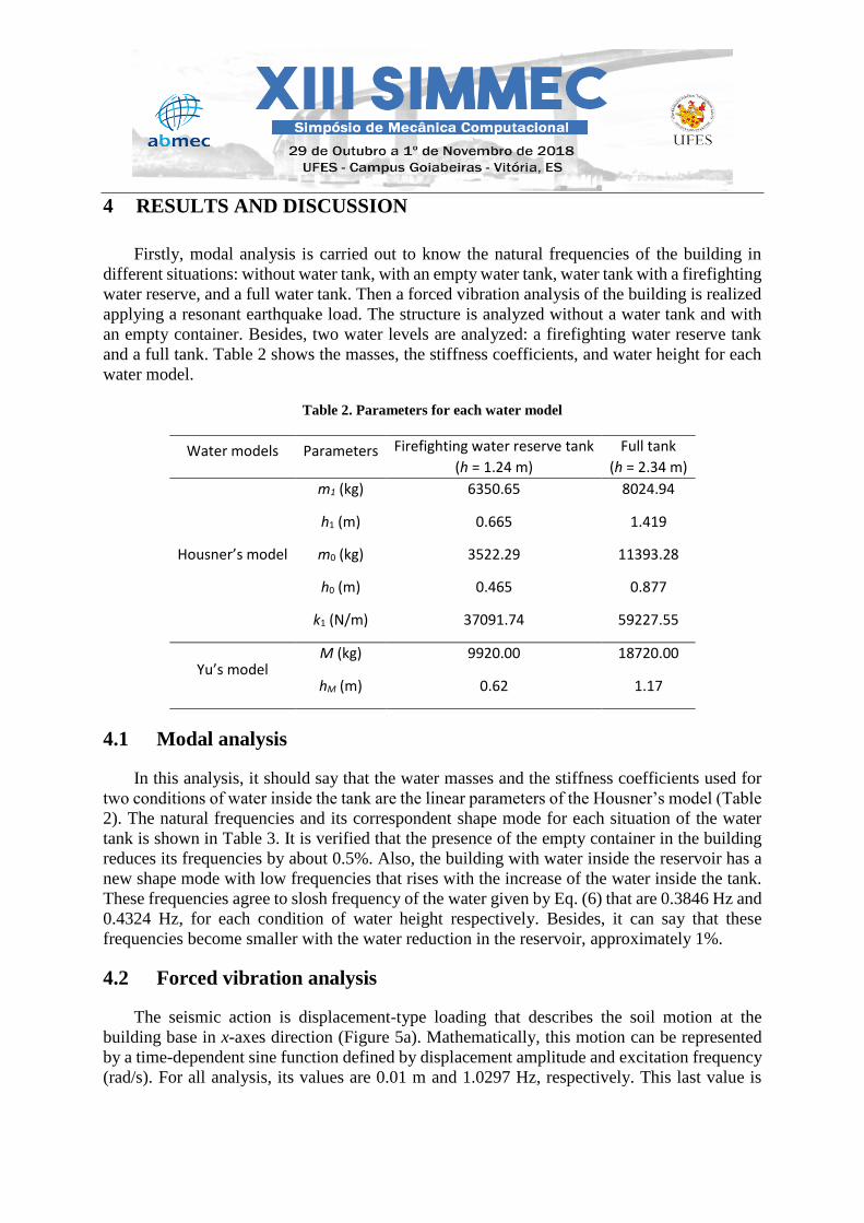
4 RESULTS AND DISCUSSION
Firstly, modal analysis is carried out to know the natural frequencies of the building in
different situations: without water tank, with an empty water tank, water tank with a firefighting
water reserve, and a full water tank. Then a forced vibration analysis of the building is realized
applying a resonant earthquake load. The structure is analyzed without a water tank and with
an empty container. Besides, two water levels are analyzed: a firefighting water reserve tank
and a full tank. Table 2 shows the masses, the stiffness coefficients, and water height for each
water model.
Table 2. Parameters for each water model
Water models Parameters Firefighting water reserve tank
(h = 1.24 m)
Full tank
(h = 2.34 m)
Housner’s model
m1 (kg) 6350.65 8024.94
h1 (m) 0.665 1.419
m0 (kg) 3522.29 11393.28
h0 (m) 0.465 0.877
k1 (N/m) 37091.74 59227.55
Yu’s model M (kg) 9920.00 18720.00
hM (m) 0.62 1.17
4.1 Modal analysis
In this analysis, it should say that the water masses and the stiffness coefficients used for
two conditions of water inside the tank are the linear parameters of the Housner’s model (Table
2). The natural frequencies and its correspondent shape mode for each situation of the water
tank is shown in Table 3. It is verified that the presence of the empty container in the building
reduces its frequencies by about 0.5%. Also, the building with water inside the reservoir has a
new shape mode with low frequencies that rises with the increase of the water inside the tank.
These frequencies agree to slosh frequency of the water given by Eq. (6) that are 0.3846 Hz and
0.4324 Hz, for each condition of water height respectively. Besides, it can say that these
frequencies become smaller with the water reduction in the reservoir, approximately 1%.
4.2 Forced vibration analysis
The seismic action is displacement-type loading that describes the soil motion at the
building base in x-axes direction (Figure 5a). Mathematically, this motion can be represented
by a time-dependent sine function defined by displacement amplitude and excitation frequency
(rad/s). For all analysis, its values are 0.01 m and 1.0297 Hz, respectively. This last value is

equal to the fundamental frequency of the structure without a tank (Table 3), characterizing the
resonance condition.
Table 3. Natural frequencies of the finite element model
Shape mode
Frequency (Hz)
No tank Empty tank Firefighting water reserve tank
(h = 1.24 m)
Full tank
(h = 2.34 m)
Bending in X-axis - - 0.3839 0.4313
Bending in X-axis 1.0297 1.0248 1.0235 1.0196
Bending in Y-axis 1.2170 1.2110 1.2043 1.1974
Bending in Y-axis 1.3712 1.3705 1.3703 1.3697
Torsion in Z-axis 2.6250 2.6098 2.6033 2.5861
Bending in X-axis 3.1024 3.0821 3.0450 2.9787
Bending in Y-axis 3.4956 3.4934 3.4922 3.4886
Torsion in Z-axis 3.9060 3.8833 3.8711 3.8303
Displacement history in time is the response analyzed for the fourth floor of the building.
The structure without a tank is in resonance as expected (Figure 7a). For the structure with an
empty tank, the beat phenomenon occurs (Figure 7b). In this case, the behavior of structure
exhibits maximum displacements in the time constant intervals. This behavior is characteristic
of the system in which excitation frequency is close to the fundamental frequency of the system
without damping. The presence of the reservoir changed the fundamental frequency of the
structure (f = 1.0248 Hz) while the applied load remained constant, justifying this phenomenon.
(a) (b)
Figure 7. Displacement vs. time of the building (a) without water tank, (b) with an empty tank

4.3 Water model evaluations
4.3.1 Yu’s model
SAP2000 (CSI, 2009) software only has two manners to enter the damping ratio: a constant
value or exponential damping. About the stiffness coefficient of springs, its value is just
constant or uses link elements with different properties. However, the use of nonlinear
equations (Eq. 7 and Eq. 8) for Yu’s model is not possible. So, the application of this model is
analytically analyzed. In this case, a mass-spring system represents the building with the water
reservoir as a 6-DOF system (Figure 5b), where the total fluid mass contributes to the damping
of the structure. The movement equation is nonlinear due to the nonlinear coefficients of
damping and stiffness. The Newmark’s method solves this equation which algorithm is
described by Accioly et al. (2017).
Figure 8 shows the displacement history for the last floor of the building of this model. In
this case, the presence of the water reduces the displacements severely. The displacement
results are lesser to full tank, but the firefighting water reserve also diminished it in less
intensity. In both analyses, the beat phenomenon does not happen.
Figure 8. Displacement vs. time of the building – Analytical solution of the Yu’s model (fexc = 1.0297 Hz)
Curves of damping ratio (Figure 9a) and stiffness coefficient (Figure 9b) along the time
allow evaluating better this model. Both parameters converge to a constant value. However,
the higher ratios are to firefighting water reserve for damping ratio and a full tank for stiffness
coefficient (Table 4).
Table 4. Damping ratio and the stiffness coefficient
Parameters Firefighting water reserve tank
(h = 1.24 m)
Full tank
(h = 2.34 m)
Damping ratio (%) 34.9 30.5
Stiffness coefficient (N/m) 2.86·105 5.10·105

(a) (b)
Figure 9. An analytic solution for Yu’s model of the building. (a) Damping ratio vs. time, (b) Stiffness
coefficient vs. time of the building
The nonlinear damping force ( )dF depends on the relative velocity among two points. For
Yu’s model, this relative speed is between the velocity of water mass ( dx ) and the velocity of
reservoir mass ( rx ). For the expression available in SAP2000 (CSI, 2009), this relative speed
is given by the velocities of nodes at the bar ends ( 1x and 2x ). These forces are written as
follows:
( ) ( )( )d d d rF t c t x x= − (10)
( ) 1 2
E
dF t C x x= − (11)
The signal of the damping force (Eq. 11) depends on the relative speed between the bar
end nodes. This force function represents an exponential curve where the user defines C and E
parameters, where C is the constant damping (Ns/m), and E is the dimensionless exponent. So,
it wishes that the damper element of the finite element model produce the same force of the
Yu’s model (Eq. 10). Besides, the relative velocity is the same for two equations. By trial and
error, it determines the C and E parameters that are shown in Table 5.
Table 5. Damping coefficient and dimensionless exponent for Yu’s model
Parameters Firefighting water reserve tank
(h = 1.24 m)
Full tank
(h = 2.34 m)
C (Ns/m) 25400 30990
E 1.2 1.4
Yu’s model is numerically analyzed using the constant values specified in Table 4, and the
parameters indicated in Table 5. In this last case, the stiffness coefficient is the same used in

the first case. The results (Figure 10a and Figure 10b, respectively) show the same behavior
found in the analytical solution (Figure 8).
(a) (b)
Figure 10. Displacement vs. time of the building of the Yu’s model (a) Constant damping, (b) Nonlinear
exponential damping
4.3.2 Housner’s model
The original model of Housner does not consider the water with the damping effect. Some
authors (Hashemi & Barji, 2016) have used this model by adding a damping ratio to represent
the viscous behavior of the water. This work evaluates this model with three different damping
ratio types: null, constant, and nonlinear exponential. Thus, the impulsive mass is added to the
mass of the reservoir structure, while a spring of constant stiffness coefficient (Eq. 3) links the
convective mass to the tank walls.
Figure 11 shows the displacement history for the last floor of the building with a damping
ratio equal null value. In this case, the water presence reduces the displacements even without
considering its damper effect. The structure displacements are smaller whether there is more
water in the reservoir. Also, the occurrence of beating is observed again, which may be justified
by the proximity between both frequencies, of the excitation and the structure (f = 1.0235 Hz
for firefighting water reserve tank; f = 1.0196 Hz for full water tank).
Figure 11. Housner’s model without damping (fexc = 1.0297 Hz)

The water model proposed by Accioly et al. (2017) is also analyzed here, i.e., the damping
coefficient is nonlinear (Eq. 8). So, it is necessary to solve this case analytically using the same
procedure previously described for Yu’s model. In this case, the reservoir mass increases by
the addition of the impulsive mass, and the convective mass substitutes the total mass for the
6-DOF system (Figure 5b).
Figure 12 shows the displacement history for the last floor of the building for this analysis.
The presence of the nonlinear damping causes a stabilizing effect on the structure that exhibits
smaller displacements when the tank is full of water. The firefighting water reserve tank also
reduces the displacements but more slowly. Besides, the beat phenomenon no more happens.
Figure 12. Displacement vs. time – Analytical solution for Housner’s model with Yu’s damping
Figure 13 shows the behavior of the damping ratio obtained by the analytical solution. This
ratio converges to a constant value for both tank types. These values are 38.9% for firefighting
water reserve tank, and 33.1% for a full tank. It is applied the same procedure described for the
Yu’s model to obtain the parameters of Eq. (11). Thus, two numerical analyses are realized.
The first one uses the constant damping (Figure 13), and the second one uses the parameters
shown in Table 6. The results show (Figure 14a and Figure 14b, respectively) the same behavior
found in the analytical solution (Figure 12).
Figure 13 – Damping ratio vs. time - Analytical solution for Housner’s model with Yu’s damping

Table 6. Damping coefficient and dimensionless exponent for Housner’s model
Parameters Firefighting water reserve tank
(h = 1.24 m)
Full tank
(h = 2.34 m)
C (Ns/m) 7000 11000
E 1.3 1.2
(a) (b)
Figure 14 - Displacement vs. time of the building for Housner’s model (a) Constant damping, (b)
Nonlinear exponential damping
5 CONCLUSIONS
The primary focus of this work is to evaluate the behavior of the water tanks as a potential
TLD, considering theoretical models of Housner (1963) and Yu et al. (1999). By the results
found, it can say that a higher water amount inside the tank provokes smaller displacements in
the structure eliminating the resonance condition and the beat phenomenon, independent of the
theoretical model used. However, the Yu’s model reduces more rapidly the displacements
comparing with the Housner’s model. Maybe because this model considers all water mass as a
damper, and the fluid-structure interaction is nonlinear. The consideration of constant or
nonlinear damping ratio does not change the final result because the curves founded are similar.
The same affirmative can say for stiffness coefficient. So, the water tank acts as a damper, but
the reservoir as designed in this work was not enough to reduce the displacements of the
structure to acceptable levels.
ACKNOWLEDGMENTS
The authors thank for the financial support provided by Fundação Cearense de Apoio à
Pesquisa – FUNCAP for the development of this work.

REFERENCES
ABNT - Associação Brasileira de Normas Técnicas, 1998. NBR 5626: Instalação predial de
água fria.
Accioly, M. E., Melo, L. P. C., Araújo, T. D., 2017. Analytical evaluation of water supply
tanks as dampers. XXXVIII Iberian Latin-American Congress on Computational Methods in
Engineering, Florianópolis, ABMEC.
CSI - Computers and Structures Inc., 2009. Analysis Reference Manual for SAP2000,
Computers and Structures Inc., Berkeley, CA.
Hashemi, M., Bargi, K., 2016. An investigation about effects of fluid-structure-soil interaction
on response modification coefficient of elevated concrete tanks. Engineering Structures and
Technologies, v. 8, pp. 1-7.
Housner, G. W., 1963. The dynamics behavior of water tanks. Bulletin of the Seismological
Society of America, v. 53, n. 2, pp. 381-387.
Kareem, A., Kijewski, T., Tamura, Y., 1999. Mitigation of motions of tall buildings with
specific examples of recent applications. Wind and Structures, v. 2, n. 3, pp. 201-251.
Livaoǧlu, R., Cakir, T., Dogangun, A., Aytekin, M., 2011. Effects of backfill on seismic
behavior of rectangular tanks. Ocean Engineering, v. 38, pp. 1161-1173.
Malekghasemi, H., Ashasi-Sorkhabi, A., Ghaemmaghami, A. R., Mercan, O., 2015.
Experimental and numerical investigations of the dynamic interaction of tuned liquid damper-
structure systems. Journal of Vibration and Control, v. 21, n. 14, pp. 2707-2720.
Miranda, P. S. T., 2010. Avaliação da Vulnerabilidade Sísmica na Realidade Predial
Brasileira. Dissertação de Mestrado, Universidade Federal do Ceará.
Nanda, B., 2010. Application of Tuned Liquid Damper for Controlling Structural Vibration.
Master thesis, National Institute of Technology/Rourkela.
Yu, J.-K., Wakahara, T., Reed, D. A., 1994. A non-linear numerical model of the tuned liquid
damper. Earthquake Engineering and Structural Analysis, pp. 671-686.