Embed Size (px)
Citation preview
DEF-C13-504/N
JUN 2009
Emissão: EDP Distribuição – Energia, S.A. DTI – Direcção de Tecnologia e Inovação R. Camilo Castelo Branco, 43 – 1º • 1050-044 Lisboa • Tel.: 210021500 • Fax: 210021444 E-mail: [email protected]
Divulgação: EDP Distribuição – Energia, S.A.
GBCO – Gabinete de Comunicação Rua Camilo Castelo Branco, 43 • 1050-044 Lisboa • Tel.: 210021684 • Fax: 210021635
INSTALAÇÕES AT E MT. SUBESTAÇÕES DE DISTRIBUIÇÃO
Sistemas de Protecção, Comando e Controlo Numéricos (SPCC)
Protocolos de comunicação
Especificação funcional
Elaboração: DTI
Homologação: conforme despacho do CA de 2009-06-03
Edição: 2ª. Anula e substitui a edição de FEV 2007
DEF-C13-504/N
JUN 2009
DTI – Direcção de Tecnologia e Inovação Pág. 2/39
ÍNDICE
0 INTRODUÇÃO ......................................................................................................................................................... 4
1 OBJECTIVO E CAMPO DE APLICAÇÃO .............................................................................................................. 4
2 NORMAS E DOCUMENTOS DE REFERÊNCIA ....................................................................................................... 4
3 TERMOS E DEFINIÇÕES .......................................................................................................................................... 4
4 PROTOCOLOS DE COMUNICAÇÃO PARA REDES LOCAIS .............................................................................. 4
4.1 Introdução ........................................................................................................................................................... 4
4.2 Requisitos gerais do sistema de comunicação ............................................................................................. 5 4.2.1 Performance ................................................................................................................................................... 5 4.2.2 Tempos máximos admitidos para as funções críticas ............................................................................. 5 4.2.3 Segurança ...................................................................................................................................................... 6 4.2.4 Flexibilidade e disponibilidade .................................................................................................................... 6 4.2.5 Expansão ......................................................................................................................................................... 6 4.2.6 Interoperabilidade ......................................................................................................................................... 6 4.2.7 Vida útil ............................................................................................................................................................ 7
4.3 Arquitectura física ............................................................................................................................................... 7
4.4 Arquitectura de comunicação ........................................................................................................................ 7 4.4.1 Camada física ................................................................................................................................................ 7 4.4.1.1 Velocidade de transmissão ..................................................................................................................... 7 4.4.1.2 Meio de transmissão ................................................................................................................................. 7 4.4.2 Camada de ligação ..................................................................................................................................... 7 4.4.3 Camada de aplicação ................................................................................................................................ 8 4.4.3.1 Leitura e escrita local ............................................................................................................................... 8 4.4.3.2 Indicações da transmissão e recepção ............................................................................................... 8 4.4.3.3 Leitura e escrita remota ........................................................................................................................... 8 4.4.3.4 Re-sincronização ....................................................................................................................................... 8 4.4.3.5 Disponibilidade e refrescamento ........................................................................................................... 8 4.4.3.6 Consistência no espaço e no tempo .................................................................................................... 8 4.4.3.7 Gestão da rede ......................................................................................................................................... 9 4.4.3.7.1 Gestão do modo de operação .......................................................................................................9 4.4.3.7.2 Gestão da configuração ...................................................................................................................9 4.4.3.7.3 Gestão de falhas e níveis de performance ....................................................................................9 4.4.3.7.4 Gestão dos serviços periódicos e não periódicos .........................................................................9 4.4.3.7.5 Gestão dos serviços de mensagem .................................................................................................9 4.4.3.7.6 Módulo de interface com a rede ................................................................................................. 10
5 PROTOCOLOS DE COMUNICAÇÃO PARA LIGAÇÃO AO CENTRO DE CONDUÇÃO - PRESCRIÇÕES GERAIS10
5.1 Introdução ......................................................................................................................................................... 10 5.1.1 Protocolo IEC 60870-5-104 .......................................................................................................................... 10
5.2 Validação da implementação do protocolo de comunicações ........................................................... 10
DEF-C13-504/N
JUN 2009
DTI – Direcção de Tecnologia e Inovação Pág. 3/39
ÍNDICE (Anexo A)
1 INTRODUCTION ....................................................................................................................................................... 3
1.1 Purpose of this document .................................................................................................................................. 3
1.2 Normative references ......................................................................................................................................... 4
1.3 General structure of application data ............................................................................................................ 4
2 PROTOCOL IMPLEMENTATION CONFORMANCE STATEMENT (PICS) .............................................................. 5
3 PROTOCOL IMPLEMENTATION EXTRA INFORMATION FOR TESTING .............................................................. 18
3.1 Communication procedures ........................................................................................................................... 18 3.1.1 Station initialization procedure .................................................................................................................. 18 3.1.2 Acquisition of events procedure ............................................................................................................... 18 3.1.3 General interrogation procedure ............................................................................................................. 19 3.1.4 Clock synchronisation procedure ............................................................................................................. 21 3.1.5 Command transmission procedure .......................................................................................................... 21 3.1.5.1 General ................................................................................................................................................. 21 3.1.5.2 Select and execute command ......................................................................................................... 21 3.1.5.3 Direct commands ................................................................................................................................ 22 3.1.5.4 Delayed commands ........................................................................................................................... 22 3.1.5.5 General comments ............................................................................................................................. 22 3.1.6 Integrated totals procedure ...................................................................................................................... 24 3.1.7 Parameter load procedure ........................................................................................................................ 24 3.1.8 Test procedure ............................................................................................................................................. 24 3.1.9 File transfer procedure ................................................................................................................................ 25
3.2 Functions ............................................................................................................................................................. 25 3.2.1 General .......................................................................................................................................................... 25 3.2.2 Time tags ....................................................................................................................................................... 25 3.2.3 Quality bits..................................................................................................................................................... 25 3.2.4 Transfer of data from Controlled Station to Controlling Station ........................................................... 26 3.2.5 Event Buffers .................................................................................................................................................. 26 3.2.6 Security .......................................................................................................................................................... 26
3.3. Addressing .......................................................................................................................................................... 26 3.3.1 Portnumber ................................................................................................................................................... 26 3.3.2 Common Address of ASDU ......................................................................................................................... 26 3.3.3 Information Object Address ....................................................................................................................... 27 3.3.4 Addressing rules ............................................................................................................................................ 27
3.4 Test requirements .............................................................................................................................................. 27 3.4.1 Type (conformance) Test ........................................................................................................................... 27 3.4.2 Special (Factory Acceptance Test) Test .................................................................................................. 28 3.4.3 Commisioning (Site Acceptance Test) test ............................................................................................. 28
DEF-C13-504/N
JUN 2009
DTI – Direcção de Tecnologia e Inovação Pág. 4/39
0 INTRODUÇÃO
O presente documento anula e substitui a edição anterior elaborada em Fevereiro de 2007. As alterações introduzidas, em relação à anterior versão, resultaram da adopção, pela EDP, do protocolo normalizado IEC 60870-5-104, a nível das comunicações entre as subestações e os Centros de Condução.
1 OBJECTIVO E CAMPO DE APLICAÇÃO
O presente documento tem como objectivo a definição funcional dos protocolos de comunicação residentes nos Sistemas de Protecção, Comando e Controlo Numéricos (SPCC) e utilizados: ⎯ nas respectivas redes locais de comunicações (RLC); ⎯ nas redes de comunicação entre os SPCC e o Centro de Condução. Serão abordados os seguintes aspectos: ⎯ prescrições gerais dos protocolos de comunicação para redes locais; ⎯ prescrições gerais e especificação funcional (Protocol Implementation Document – PID) do
protocolo de comunicação para ligação ao Centro de Condução.
2 NORMAS E DOCUMENTOS DE REFERÊNCIA
Os documentos normativos seguintes contêm prescrições que, através de referência neste texto, constituem disposições válidas para o presente documento. Estas referências normativas são citadas nos locais adequados no texto e as publicações são listadas abaixo.
Quaisquer alterações das referidas edições listadas só serão aplicáveis no âmbito do presente documento se forem objecto de inclusão específica, por modificação ou aditamento ao mesmo.
EDP Full PID 104 Final version 1.0
2007 Full Protocol Implementation Document for IEC 60870-5-104
IEC 60870-5-104 2006 Telecontrol equipment and systems - Part 5-104: Transmission protocols - Network access for IEC 60870-5-101 using standard transport profiles
IEEE Std 1646 2004 Communication delivery time performance requirements for electric power substation automation
3 TERMOS E DEFINIÇÕES
Para efeitos do presente documento, são aplicáveis as definições constantes das normas IEC 60870-5-104 e IEEE Std 1646.
4 PROTOCOLOS DE COMUNICAÇÃO PARA REDES LOCAIS
4.1 Introdução
Os protocolos de comunicações a utilizar na rede local de comunicações (RLC) dos SPCC deverão seguir uma solução caracterizada por uma alta fiabilidade e performance na transmissão de dados, garantindo uma grande flexibilidade na implementação de futuros upgrades do SPCC. Os protocolos de comunicações devem ser normalizados, preferencialmente de acordo com a normalização IEC aplicável, desde o nível físico até ao nível de aplicação, e a sua escolha deve ser feita tendo em consideração a arquitectura física do SPCC e os tempos mínimos exigidos no relacionamento inter-funcional dos sistemas.
DEF-C13-504/N
JUN 2009
DTI – Direcção de Tecnologia e Inovação Pág. 5/39
4.2 Requisitos gerais do sistema de comunicação
4.2.1 Performance
A performance poderá variar de acordo com a distribuição das funções pelos vários níveis do SPCC, mas terá sempre de ser adequada à natureza crítica dos dados a transmitir e aos tempos de resposta a atingir. Deverá também ser garantida uma elevada consistência temporal, necessária para satisfazer: ⎯ cronologia correcta; ⎯ operações cíclicas; ⎯ sincronização de acções; ⎯ operações multitarefas; ⎯ controlo sequencial; ⎯ imagem correcta da evolução do processo; Para obtenção desta consistência temporal será necessário: ⎯ sincronização por “broadcast” e/ou GPS (Global Position System) ou por protocolo de
comunicações; ⎯ minimização do tempo de aquisição de dados; ⎯ optimização do tempo de resposta; ⎯ elevada capacidade de gestão temporal; ⎯ uniformidade do tempo de resposta em toda a rede; ⎯ eliminação de paragens e retransmissões intermédias; ⎯ minimização das mensagens de "overhead".
4.2.2 Tempos máximos admitidos para as funções críticas
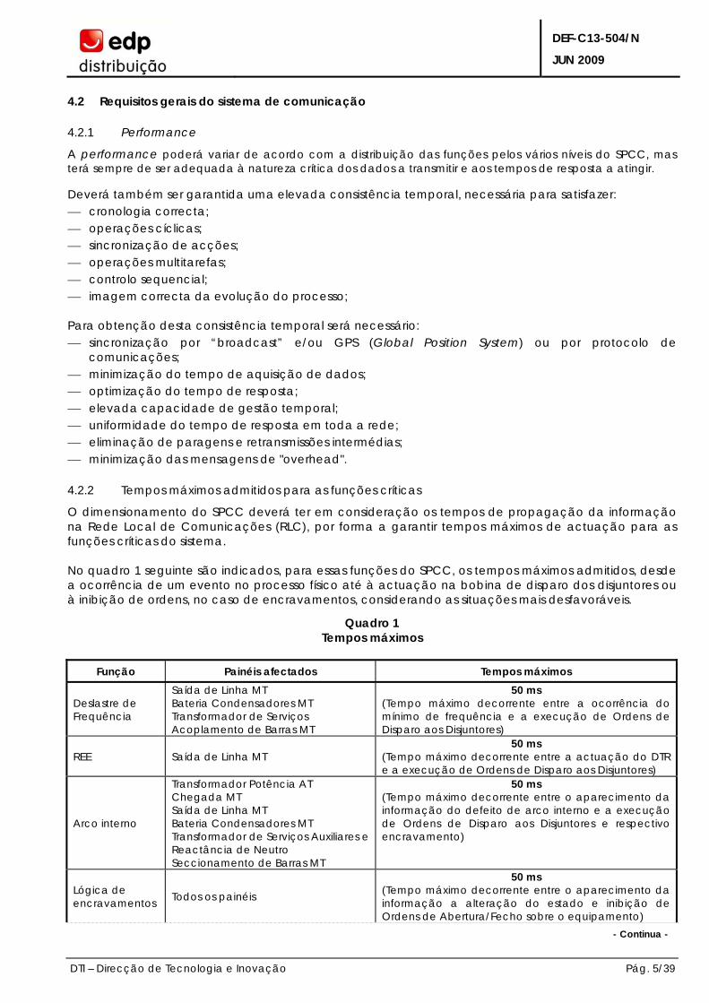
O dimensionamento do SPCC deverá ter em consideração os tempos de propagação da informação na Rede Local de Comunicações (RLC), por forma a garantir tempos máximos de actuação para as funções críticas do sistema. No quadro 1 seguinte são indicados, para essas funções do SPCC, os tempos máximos admitidos, desde a ocorrência de um evento no processo físico até à actuação na bobina de disparo dos disjuntores ou à inibição de ordens, no caso de encravamentos, considerando as situações mais desfavoráveis.
Quadro 1 Tempos máximos
Função Painéis afectados Tempos máximos
Deslastre de Frequência
Saída de Linha MT Bateria Condensadores MT Transformador de Serviços Acoplamento de Barras MT
50 ms (Tempo máximo decorrente entre a ocorrência do mínimo de frequência e a execução de Ordens de Disparo aos Disjuntores)
REE
Saída de Linha MT
50 ms (Tempo máximo decorrente entre a actuação do DTR e a execução de Ordens de Disparo aos Disjuntores)
Arco interno
Transformador Potência AT Chegada MT Saída de Linha MT Bateria Condensadores MT Transformador de Serviços Auxiliares e Reactância de Neutro Seccionamento de Barras MT
50 ms (Tempo máximo decorrente entre o aparecimento da informação do defeito de arco interno e a execução de Ordens de Disparo aos Disjuntores e respectivo encravamento)
Lógica de encravamentos Todos os painéis
50 ms (Tempo máximo decorrente entre o aparecimento da informação a alteração do estado e inibição de Ordens de Abertura/Fecho sobre o equipamento)
- Continua -
DEF-C13-504/N
JUN 2009
DTI – Direcção de Tecnologia e Inovação Pág. 6/39
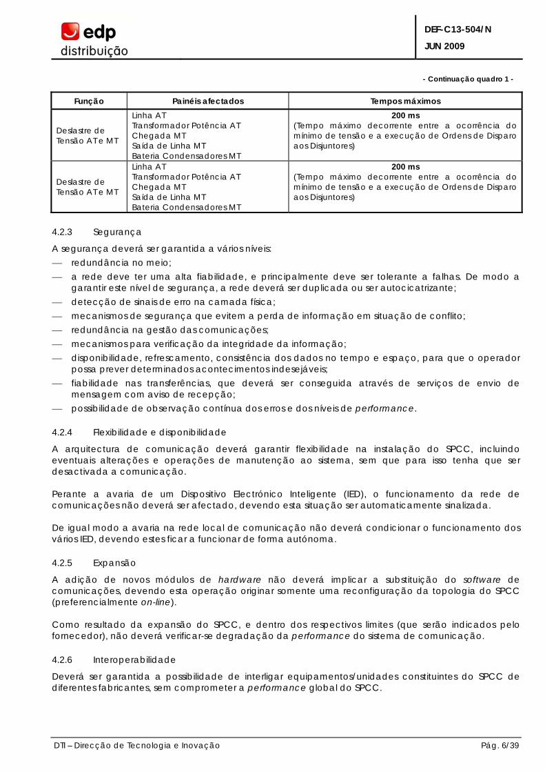
- Continuação quadro 1 -
Função Painéis afectados Tempos máximos
Deslastre de Tensão AT e MT
Linha AT Transformador Potência AT Chegada MT Saída de Linha MT Bateria Condensadores MT
200 ms (Tempo máximo decorrente entre a ocorrência do mínimo de tensão e a execução de Ordens de Disparo aos Disjuntores)
Deslastre de Tensão AT e MT
Linha AT Transformador Potência AT Chegada MT Saída de Linha MT Bateria Condensadores MT
200 ms (Tempo máximo decorrente entre a ocorrência do mínimo de tensão e a execução de Ordens de Disparo aos Disjuntores)
4.2.3 Segurança
A segurança deverá ser garantida a vários níveis: ⎯ redundância no meio; ⎯ a rede deve ter uma alta fiabilidade, e principalmente deve ser tolerante a falhas. De modo a
garantir este nível de segurança, a rede deverá ser duplicada ou ser autocicatrizante; ⎯ detecção de sinais de erro na camada física; ⎯ mecanismos de segurança que evitem a perda de informação em situação de conflito; ⎯ redundância na gestão das comunicações; ⎯ mecanismos para verificação da integridade da informação; ⎯ disponibilidade, refrescamento, consistência dos dados no tempo e espaço, para que o operador
possa prever determinados acontecimentos indesejáveis; ⎯ fiabilidade nas transferências, que deverá ser conseguida através de serviços de envio de
mensagem com aviso de recepção; ⎯ possibilidade de observação contínua dos erros e dos níveis de performance.
4.2.4 Flexibilidade e disponibilidade
A arquitectura de comunicação deverá garantir flexibilidade na instalação do SPCC, incluindo eventuais alterações e operações de manutenção ao sistema, sem que para isso tenha que ser desactivada a comunicação. Perante a avaria de um Dispositivo Electrónico Inteligente (IED), o funcionamento da rede de comunicações não deverá ser afectado, devendo esta situação ser automaticamente sinalizada. De igual modo a avaria na rede local de comunicação não deverá condicionar o funcionamento dos vários IED, devendo estes ficar a funcionar de forma autónoma.
4.2.5 Expansão
A adição de novos módulos de hardware não deverá implicar a substituição do software de comunicações, devendo esta operação originar somente uma reconfiguração da topologia do SPCC (preferencialmente on-line). Como resultado da expansão do SPCC, e dentro dos respectivos limites (que serão indicados pelo fornecedor), não deverá verificar-se degradação da performance do sistema de comunicação.
4.2.6 Interoperabilidade
Deverá ser garantida a possibilidade de interligar equipamentos/unidades constituintes do SPCC de diferentes fabricantes, sem comprometer a performance global do SPCC.
DEF-C13-504/N
JUN 2009
DTI – Direcção de Tecnologia e Inovação Pág. 7/39
4.2.7 Vida útil
A arquitectura de comunicação seleccionada deve permitir a coexistência de diferentes tipos e gerações de equipamentos/unidades constituintes do SPCC, com diferentes funções e capacidade.
4.3 Arquitectura física
O protocolo deverá poder ser usado em arquitecturas de SPCC do tipo centralizada ou descentralizada. A inteligência, o controlo e a base de dados deverão poder ser distribuídos pelos vários IED.
4.4 Arquitectura de comunicação
A arquitectura de comunicação deverá seguir preferencialmente uma topologia tipo bus que permita o uso de fibras ópticas. O protocolo de comunicações deverá usar como referência o modelo ISO, constituído preferencialmente pelas camadas Física, Ligação e Aplicação.
4.4.1 Camada física
A camada física será responsável por assegurar a transferência de informação dum equipamento para todos os outros interligados ao bus. Os equipamentos e elementos a fornecer serão: ⎯ fibras ópticas em mono modo com 1 300 nm; ⎯ os conectores deverão do tipo MTRJ na ligação aos repartidores (Switches) e do tipo ST na ligação
ao IED.
4.4.1.1 Velocidade de transmissão
A definição da velocidade de transmissão deverá ser feita tendo em consideração que devem ser garantidos os tempos mínimos de actuação exigidos para o funcionamento do SPCC. O sistema deverá ter a possibilidade de atribuir velocidades diferentes para requisitos funcionais diferentes de acordo com a caracterização funcional do sistema. As velocidades de comunicação mínimas serão de 10 Mbytes.
4.4.1.2 Meio de transmissão
O meio de transmissão deverá assegurar as seguintes características: ⎯ imunidade a interferências electromagnéticas, segundo as normas IEC 61000 e IEEE C37.90; ⎯ isolamento galvânico através de acopladores ópticos; ⎯ suporte em fibra óptica.
4.4.2 Camada de ligação
A camada de ligação deverá fornecer dois tipos de serviços de transmissão: ⎯ troca de variáveis identificadas; ⎯ transferência de mensagens. Estas trocas poderão acontecer: ⎯ ciclicamente; ⎯ os nomes dos objectos e a sua prioridade deverão ser estabelecidos quando o sistema é configurado; ⎯ sob um explícito pedido do utilizador.
DEF-C13-504/N
JUN 2009
DTI – Direcção de Tecnologia e Inovação Pág. 8/39
Estes pedidos farão com que os valores de uma ou mais variáveis ou de uma ou mais mensagens circulem no bus.
4.4.3 Camada de aplicação
Os serviços fornecidos pela camada de ligação e utilizados pela camada de aplicação deverão ser de dois tipos: ⎯ serviços periódicos e aperiódicos:
⎯ serviços de leitura e escrita local; ⎯ serviços de leitura e escrita remota; ⎯ indicações da transmissão e recepção da variável; ⎯ informação actualizada da informação consumida; ⎯ informação da consistência dos dados no espaço e no tempo; ⎯ serviços de mensagem baseados no MMS da ISO.
4.4.3.1 Leitura e escrita local
A camada de aplicação fornece aos utilizadores serviços locais de leitura e escrita de variáveis. Estes serviços utilizarão serviços da camada de ligação para colocar valores nos buffers ou remover valores dos buffers. Estes serviços não geram tráfego no bus.
4.4.3.2 Indicações da transmissão e recepção
O utilizador deverá ser informado da transmissão e da recepção duma variável identificada. Ele poderá então usar esta informação, por exemplo, para se sincronizar a si próprio com uma parte da informação da rede. Quando a camada de aplicação receber uma indicação de transmissão ou recepção para uma variável produzida ou consumida, deverá avançar com esta indicação para o utilizador.
4.4.3.3 Leitura e escrita remota
A camada de aplicação será a responsável pela implementação dos serviços de leitura e escrita remotos para variáveis identificadas.
4.4.3.4 Re-sincronização
A camada de aplicação tornará possível a participação de processos de aplicações assíncronas em aplicações síncronas distribuídas. O mecanismo de re-sincronização necessitará de duplicação de memória ao nível da camada de aplicação; deverá ser acessível através dos processos de aplicação da rede, que deslocará ou depositará valores.
4.4.3.5 Disponibilidade e refrescamento
Quando o utilizador lê uma variável na sua entidade de comunicação local, ele deverá poder ao mesmo tempo receber informação qualitativa respeitante ao estado da variável. A disponibilidade e o refrescamento podem ser síncronos, assíncronos e pontuais. O ciclo de refrescamento dos dados deve ser compatível com o ciclo de aquisição de informação das unidades de painel, tendo em conta os princípios de operação e origem.
4.4.3.6 Consistência no espaço e no tempo
Deverá ser garantida uma consistência dos dados quer no espaço quer no tempo. Deverão ser criados mecanismos que forneçam ao utilizador o estado da informação que ele consome.
DEF-C13-504/N
JUN 2009
DTI – Direcção de Tecnologia e Inovação Pág. 9/39
De igual modo o utilizador deverá conhecer o estado correcto da informação em todas as entidades de comunicação que a utilizam.
4.4.3.7 Gestão da rede
Deverão existir duas famílias de serviços de gestão da rede: ⎯ baseados nos serviços periódicos e aperiódicos; ⎯ baseados nos serviços de mensagem. O fornecedor deverá especificar a forma como irá desempenhar as funções seguidamente referidas.
4.4.3.7.1 Gestão do modo de operação
Comandos de “Start / Stop”.
Comandos de validação / invalidação.
Comandos de Reset.
Funções de leitura / escrita.
4.4.3.7.2 Gestão da configuração
Criação dos objectos.
Destruição dos objectos.
Arranque / paragem das entidades de comunicação.
4.4.3.7.3 Gestão de falhas e níveis de performance
Leitura de contadores.
Colocar os contadores a zero.
4.4.3.7.4 Gestão dos serviços periódicos e não periódicos Estes serviços serão usados para: ⎯ atribuição dum endereço físico e um “tagName”; ⎯ “downloading” remoto dos identificadores; ⎯ leitura remota (releitura da configuração); ⎯ operações de controlo remoto; ⎯ monitorização remota; ⎯ registos (todos os contadores de erros e equipamentos de avaliação do nível de performance); ⎯ gestão de uma presença ou variável de identificação; ⎯ gestão de uma lista de estações presentes.
4.4.3.7.5 Gestão dos serviços de mensagem Os serviços de Mensagem serão usados para: ⎯ criar objectos (entidades de aplicação, variáveis, ciclos elementares, etc.); ⎯ eliminar objectos; ⎯ “download” de configurações ⎯ “upload” de configurações; ⎯ controlo remoto da subestação.
DEF-C13-504/N
JUN 2009
DTI – Direcção de Tecnologia e Inovação Pág. 10/39
4.4.3.7.6 Módulo de interface com a rede Deverá existir um módulo de interface com a rede, ao nível da unidade de painel, que assegure as funções essenciais enunciadas a seguir: ⎯ saída de dados dos ficheiros apropriados:
⎯ comandos remotos que geralmente são urgentes; ⎯ entradas digitais urgentes; ⎯ entradas digitais normais; ⎯ entradas digitais lentas; ⎯ medidas analógicas urgentes; ⎯ medidas analógicas normais; ⎯ medidas analógicas lentas; ⎯ entradas de informação do sistema; ⎯ saídas de informação do sistema;
⎯ filtragem dos dados de entrada, que consiste em pôr à disposição da unidade de painel somente os dados significativos (alteração do estado duma entrada digital ou variação significativa duma medida analógica);
⎯ aquisição da data e consequente tratamento para difusão e sincronização; ⎯ gestão das transmissões em modo de mensagem (tendo em conta os acontecimentos datados, os
parâmetros de setting dos relés, função de trace, etc.).
5 PROTOCOLOS DE COMUNICAÇÃO PARA LIGAÇÃO AO CENTRO DE CONDUÇÃO – PRESCRIÇÕES GERAIS
5.1 Introdução
De acordo com a localização da subestação o SPCC deve garantir a interligação com o Centro de Condução respectivo que, no universo da EDP Distribuição, será efectuada através do Protocolo de Comunicação IEC 60870-5-104 normalizado indicado no seguimento.
5.1.1 Protocolo IEC 60870-5-104
O protocolo de comunicações IEC 60870-5-104 utilizado pela EDP Distribuição é baseado no documento “Full Protocol Implementation Document for IEC 60870-5-104”, na sua versão mais actualizada, conforme definido no Anexo A do presente documento.
5.2 Validação da implementação do protocolo de comunicações
O protocolo de comunicações a utilizar para a interligação do SPCC ao Centro de Condução será validado através da realização de ensaios funcionais. ANEXOS
Anexo A - documento “Full Protocol Implementation Document for IEC 60870-5-104”.
DEF-C13-504/N
JUN 2009
DTI – Direcção de Tecnologia e Inovação Pág. 11/39
ANEXO A
AO
DEF-C13-504/N
“Full Protocol Implementation Document for IEC 60870-5-104”
IEC 60870-5-104 EDP-Energias de Portugal Full Protocol Implementation Document (EDP PID 104)
Final Version EDP PID 104 page 1
EDP - Energias de Portugal
Full Protocol Implementation Document for IEC 60870-5-104
Final version 1.0
Change log
Revision no.:
Date: Chapter: Comments: Author:
0.1 03.05.2007 All Initial version MAdr KEMA
0.2 15.06.2007 All Changes according document:
070614 comments on PID 030601
WKF KEMA
0.3 19.06.2007 All Quality review by John Jansen van der Sligte JJS KEMA
0.4 09.07.2007 All Changes according document
070619 comments EDP on PID and conference call from 06.07.2007
MAdr KEMA
0.5 11.07.2007 All Changes according document
070711 comments EDP on PID EDP team
0.9 23.07.2007 3.1.2 Events during GI requirement is deleted in PID MAdr KEMA
1.0 18.12.2007 n.a. Final Version WKF KEMA
IEC 60870-5-104 EDP-Energias de Portugal Full Protocol Implementation Document (EDP PID 104)
Final Version EDP PID 104 page 2
TABLE OF CONTENTS
1 INTRODUCTION ................................................................................................................................ 3
1.1 Purpose of this document ............................................................................................................ 3
1.2 Normative references .................................................................................................................. 4
1.3 General structure of application data ...................................................................................... 4
2 PROTOCOL IMPLEMENTATION CONFORMANCE STATEMENT (PICS) ........................................ 5
3 PROTOCOL IMPLEMENTATION EXTRA INFORMATION FOR TESTING ........................................ 18
3.1 Communication procedures .................................................................................................... 18 3.1.1 Station initialisation procedure ............................................................................................ 18 3.1.2 Acquisition of events procedure ......................................................................................... 18 3.1.3 General interrogation procedure ....................................................................................... 19 3.1.4 Clock synchronisation procedure ....................................................................................... 21 3.1.5 Command transmission procedure .................................................................................... 21 3.1.5.1 General ........................................................................................................................... 21 3.1.5.2 Select and execute command .................................................................................. 21 3.1.5.3 Direct commands .......................................................................................................... 22 3.1.5.4 Delayed commands ..................................................................................................... 22 3.1.5.5 General comments ....................................................................................................... 22 3.1.6 Integrated totals procedure ................................................................................................ 24 3.1.7 Parameter load procedure ................................................................................................. 24 3.1.8 Test procedure ....................................................................................................................... 24 3.1.9 File transfer procedure .......................................................................................................... 25
3.2 Functions ...................................................................................................................................... 25 3.2.1 General ................................................................................................................................... 25 3.2.2 Time tags ................................................................................................................................. 25 3.2.3 Quality bits .............................................................................................................................. 25 3.2.4 Transfer of data from Controlled Station to Controlling Station ..................................... 26 3.2.5 Event Buffers ........................................................................................................................... 26 3.2.6 Security .................................................................................................................................... 26
3.3 Addressing .................................................................................................................................... 26 3.3.1 Portnumber ............................................................................................................................. 26 3.3.2 Common Address of ASDU .................................................................................................. 26 3.3.3 Information Object Address ................................................................................................. 27 3.3.4 Addressing rules ..................................................................................................................... 27
3.4 Test requirements ........................................................................................................................ 27 3.4.1 Type (conformance) Test ..................................................................................................... 27 3.4.2 Special (Factory Acceptance Test) Test ............................................................................ 28 3.4.3 Commisioning (Site Acceptance Test) test ....................................................................... 28
IEC 60870-5-104 EDP-Energias de Portugal Full Protocol Implementation Document (EDP PID 104)
Final Version EDP PID 104 page 3
1 INTRODUCTION
The IEC Technical Committee 57 (Working Group 03) has developed a protocol standard for telecontrol, teleprotection, and associated telecommunications for electric power systems. The result of this work is IEC 60870-5. Five documents specify the base IEC 60870-5. These documents are:
IEC 60870-5-1 Transmission Frame Formats
IEC 60870-5-2 Data Link Transmission Services
IEC 60870-5-3 General Structure of Application Data
IEC 60870-5-4 Definition and coding of Information Elements
IEC 60870-5-5 Basic Application Functions The IEC Technical Committee 57 has also generated a companion standard IEC 60870-5-101. In addition to the CS101 standard a further companion standard IEC 60870-5-104 called “Transmission protocols – Network access for IEC 60870-5-101 using standard transport profiles” which is closely related to IEC 60870-5-101 was defined. Both IEC 60870-5-101 and IEC 60870-5-104 are based on the five documents IEC 60870-5-1 till 5. In addition to these standards WG03 has defined conformance test procedures and testcases that are defined in IEC60870-5-6. In spite of the great care with which the authors have written this document, possible indistinctness and inaccuracies can still occur in this document. It is the responsibility of the vendor to identify possible indistinctness and inaccuracies in this document, and the consistency between the EDP-Energias de Portugal PID 104 and related IEC60870-5 standards. If indistinctness, inaccuracies, or inconsistencies between the EDP-Energias de Portugal PID 104 or other EDP-Energias de Portugal requirements, and the related IEC60870-5 standard are identified, it is the responsibility of the vendor to inform the contact person within EDP-Energias de Portugal to discuss these issues.
1.1 Purpose of this document
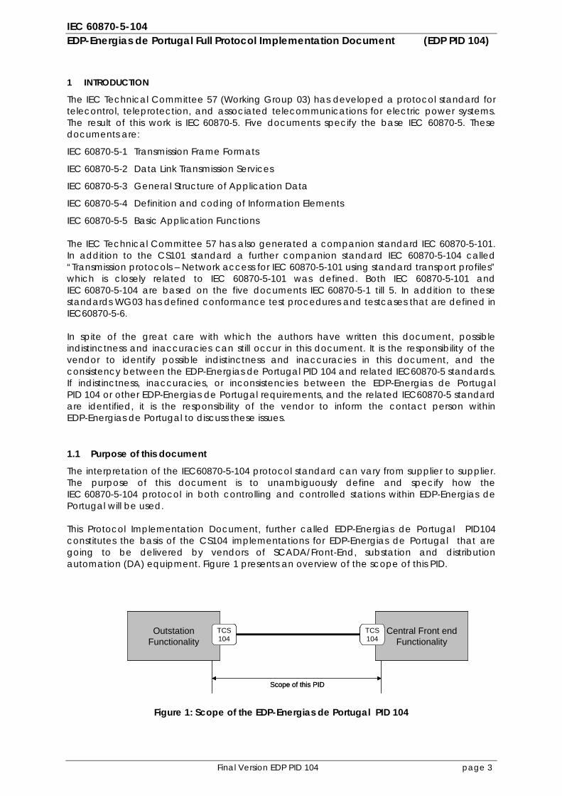
The interpretation of the IEC60870-5-104 protocol standard can vary from supplier to supplier. The purpose of this document is to unambiguously define and specify how the IEC 60870-5-104 protocol in both controlling and controlled stations within EDP-Energias de Portugal will be used. This Protocol Implementation Document, further called EDP-Energias de Portugal PID104 constitutes the basis of the CS104 implementations for EDP-Energias de Portugal that are going to be delivered by vendors of SCADA/Front-End, substation and distribution automation (DA) equipment. Figure 1 presents an overview of the scope of this PID.
Figure 1: Scope of the EDP-Energias de Portugal PID 104
OutstationFunctionality
TCS104
Central Front endFunctionality
TCS104
Scope of this PID
OutstationFunctionality
TCS104
OutstationFunctionality
TCS104
Central Front endFunctionality
TCS104
Central Front endFunctionality
TCS104
Scope of this PID
IEC 60870-5-104 EDP-Energias de Portugal Full Protocol Implementation Document (EDP PID 104)
Final Version EDP PID 104 page 4
1.2 Normative references
This EDP-Energias de Portugal PID104 is based on the below mentioned IEC standards:
• IEC 60870-5-1: 1990, Telecontrol equipment and systems - Part 1: Transmission frame formats
• IEC 60870-5-2: 1992, Telecontrol equipment and systems - Part 2: Link transmission procedures
• IEC 60870-5-3: 1992, Telecontrol equipment and systems - Part 3: General structure of application data
• IEC 60870-5-4: 1993, Telecontrol equipment and systems - Part 4: Definition and coding of application information elements
• IEC 60870-5-5: 1995, Telecontrol equipment and systems - Part 5: Basic application functions
• IEC 60870-5-101 ed.2: 2003, Telecontrol equipment and systems - Section 101: Companion standard for basic telecontrol tasks
• IEC 60870-5-104 ed.2 2006, Telecontrol equipment and systems - Section 104: Network acces for CS101 using standard transport profiles
• IEC 60870-5-6, Guidelines for conformance testing for the IEC 60870-5 companion standards
1.3 General structure of application data
IEC 870-5-3 describes the Basic Application Data Units in transmission frames of telecontrol systems. This subclass selects specific field elements out of that standard and defines Application Service Data Units (ASDU) used in the CS104 protocol.
The Application Service Data Units (ASDU) is composed of a Data Unit Identifier and one or more Information Objects. The Data Unit Identifier has always the same structure for all ASDUs. The Information Objects of an ASDU are always of the same structure and type, which are defined in the Type Identification field.
The structure of the Data Unit Identifier is:
- Type identification - Variable structure qualifier - Cause of transmission (Originator Address is not used in the EDP-Energias de Portugal PID104
and therefore set to 0) - Common address of ASDU - Information object address
IEC 60870-5-104 EDP-Energias de Portugal Full Protocol Implementation Document (EDP PID 104)
Final Version EDP PID 104 page 5
2 PROTOCOL IMPLEMENTATION CONFORMANCE STATEMENT (PICS)
Interoperability list
The marked functions and ASDUs in the interoperability list on the following pages represent the current minimum requirements for an IEC 60870-5-104 system according to the EDP-Energias de Portugal PID 104.
This PID presents sets of parameters and alternatives from which subsets must be selected to implement particular telecontrol systems. Certain parameter values, such as the choice of “structured“ or “unstructured“ fields of the INFORMATION OBJECT ADDRESS of ASDUs represent mutually exclusive alternatives. This means that only one value of the defined parameters is admitted per system. Other parameters, such as the listed set of different process information in command and in monitor direction allow the specification of the complete set or subsets, as appropriate for given applications. This clause summarizes the parameters of the previous clauses to facilitate a suitable selection for a specific application. If a system is composed of equipment stemming from different manufacturers it is necessary that all partners agree on the selected parameters.
The interoperability list is defined as in IEC 60870-5-101 and IEC 60870-5-104. The text descriptions of parameters which are not applicable to the CS104 companion standard are strike-through (corresponding check box is marked black).
Note: - In addition, the full specification of a system may require individual selection of certain parameters for certain parts of the system, such as the individual selection of scaling factors for individually addressable measured values.
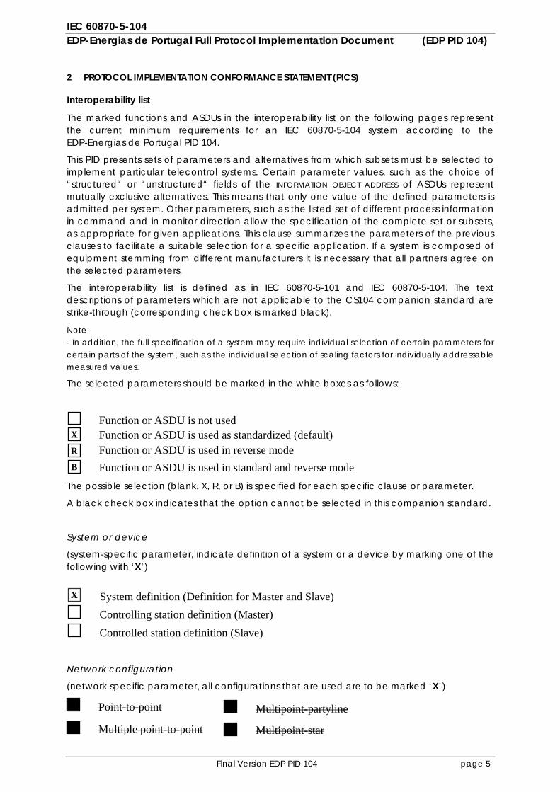
The selected parameters should be marked in the white boxes as follows:
The possible selection (blank, X, R, or B) is specified for each specific clause or parameter.
A black check box indicates that the option cannot be selected in this companion standard.
System or device
(system-specific parameter, indicate definition of a system or a device by marking one of the following with ‘X’)
Network configuration
(network-specific parameter, all configurations that are used are to be marked ‘X’)
System definition (Definition for Master and Slave) Controlling station definition (Master)
Function or ASDU is used as standardized (default) Function or ASDU is used in reverse mode Function or ASDU is used in standard and reverse mode
X
R
B
X
Function or ASDU is not used
Point-to-point
Multiple point-to-point
Multipoint-partyline
Multipoint-star
Controlled station definition (Slave)
IEC 60870-5-104 EDP-Energias de Portugal Full Protocol Implementation Document (EDP PID 104)
Final Version EDP PID 104 page 6
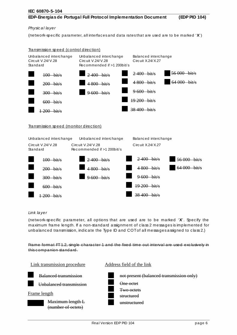
Physical layer
(network-specific parameter, all interfaces and data rates that are used are to be marked ‘X’)
Transmission speed (control direction) Unbalanced interchange Unbalanced interchange Balanced interchange Circuit V.24/V.28 Circuit V.24/V.28 Circuit X.24/X.27 Standard Recommended if >1 200bit/s
Transmission speed (monitor direction)
Unbalanced interchange Unbalanced interchange Balanced interchange
Circuit V.24/V.28 Circuit V.24/V.28 Circuit X.24/X.27 Standard Recommended if >1 200bit/s
Link layer
(network-specific parameter, all options that are used are to be marked ‘X’. Specify the maximum frame length. If a non-standard assignment of class 2 messages is implemented for unbalanced transmission, indicate the Type ID and COT of all messages assigned to class 2.)
Frame format FT 1.2, single character 1 and the fixed time out interval are used exclusively in this companion standard.
100 bit/s
200 bit/s
300 bit/s
600 bit/s
1 200 bit/s
2 400 bit/s
4 800 bit/s
9 600 bit/s
2 400 bit/s
4 800 bit/s
9 600 bit/s
19 200 bit/s
38 400 bit/s
56 000 bit/s
64 000 bit/s
100 bit/s
200 bit/s
300 bit/s
600 bit/s
1 200 bit/s
2 400 bit/s
4 800 bit/s
9 600 bit/s
2 400 bit/s
4 800 bit/s
9 600 bit/s
19 200 bit/s
38 400 bit/s
56 000 bit/s
64 000 bit/s
Balanced transmission
Unbalanced transmission
Maximum length L (number of octets)
Link transmission procedure Address field of the link
not present (balanced transmission only) One octet Two octetsstructured unstructured
Frame length
IEC 60870-5-104 EDP-Energias de Portugal Full Protocol Implementation Document (EDP PID 104)
Final Version EDP PID 104 page 7
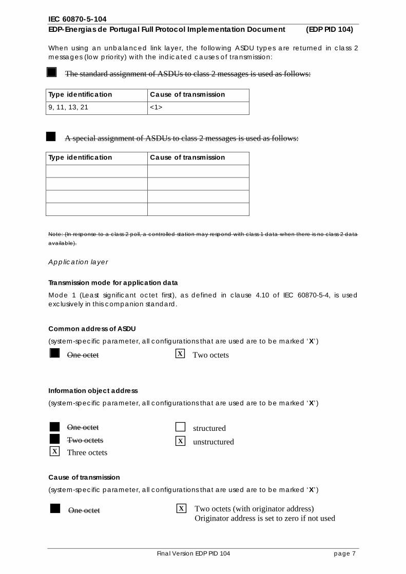
When using an unbalanced link layer, the following ASDU types are returned in class 2 messages (low priority) with the indicated causes of transmission:
Type identification Cause of transmission
9, 11, 13, 21 <1>
Type identification Cause of transmission
Note: (In response to a class 2 poll, a controlled station may respond with class 1 data when there is no class 2 data available).
Application layer Transmission mode for application data
Mode 1 (Least significant octet first), as defined in clause 4.10 of IEC 60870-5-4, is used exclusively in this companion standard.
Common address of ASDU
(system-specific parameter, all configurations that are used are to be marked ‘X’)
Information object address
(system-specific parameter, all configurations that are used are to be marked ‘X’)
Cause of transmission
(system-specific parameter, all configurations that are used are to be marked ‘X’)
One octet Two octets
One octet structured Two octets unstructured Three octets
One octet Two octets (with originator address) Originator address is set to zero if not used
X
X
X
X
The standard assignment of ASDUs to class 2 messages is used as follows:
A special assignment of ASDUs to class 2 messages is used as follows:
IEC 60870-5-104 EDP-Energias de Portugal Full Protocol Implementation Document (EDP PID 104)
Final Version EDP PID 104 page 8
Length of APDU
(system-specific parameter, specify the maximum length of the APDU per system) Length of the APDU must be configurable with a maximum length of 253 (default). The maximum length may be reduced per system.
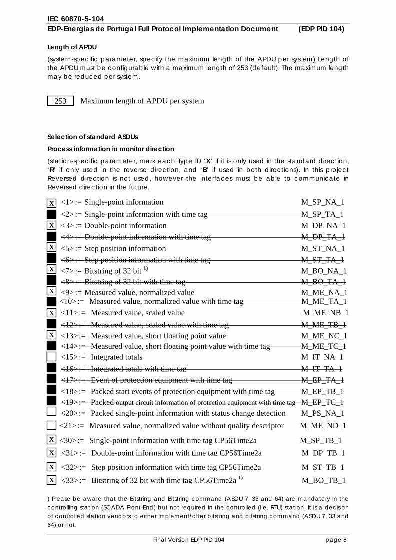
Selection of standard ASDUs
Process information in monitor direction
(station-specific parameter, mark each Type ID ‘X’ if it is only used in the standard direction, ‘R’ if only used in the reverse direction, and ‘B’ if used in both directions). In this project Reversed direction is not used, however the interfaces must be able to communicate in Reversed direction in the future.
) Please be aware that the Bitstring and Bitstring command (ASDU 7, 33 and 64) are mandatory in the controlling station (SCADA Front-End) but not required in the controlled (i.e. RTU) station. It is a decision of controlled station vendors to either implement/offer bitstring and bitstring command (ASDU 7, 33 and 64) or not.
<1> := Single-point information M_SP_NA_1
<30> := Single-point information with time tag CP56Time2a M_SP_TB_1<31> := Double-point information with time tag CP56Time2a M DP TB 1
<32> := Step position information with time tag CP56Time2a M ST TB 1
<33> := Bitstring of 32 bit with time tag CP56Time2a 1) M_BO_TB_1
<2> := Single-point information with time tag M_SP_TA_1 <3> := Double-point information M DP NA 1<4> := Double-point information with time tag M_DP_TA_1<5> := Step position information M_ST_NA_1 <6> := Step position information with time tag M_ST_TA_1 <7> := Bitstring of 32 bit 1) M_BO_NA_1 <8> := Bitstring of 32 bit with time tag M_BO_TA_1 <9> := Measured value, normalized value M_ME_NA_1 <10> := Measured value, normalized value with time tag M_ME_TA_1 <11> := Measured value, scaled value M_ME_NB_1<12> := Measured value, scaled value with time tag M_ME_TB_1 <13> := Measured value, short floating point value M_ME_NC_1 <14> := Measured value, short floating point value with time tag M_ME_TC_1 <15> := Integrated totals M IT NA 1<16> := Integrated totals with time tag M IT TA 1<17> := Event of protection equipment with time tag M_EP_TA_1 <18> := Packed start events of protection equipment with time tag M_EP_TB_1<19> := Packed output circuit information of protection equipment with time tag M_EP_TC_1<20> := Packed single-point information with status change detection M_PS_NA_1 <21> := Measured value, normalized value without quality descriptor M_ME_ND_1
X
X
X
X
X
X
X
X
X
X
X
253 Maximum length of APDU per system
IEC 60870-5-104 EDP-Energias de Portugal Full Protocol Implementation Document (EDP PID 104)
Final Version EDP PID 104 page 9
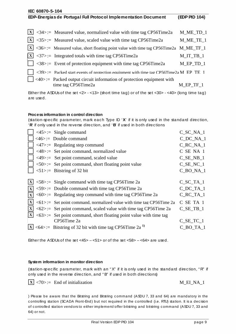
Either the ASDUs of the set <2> - <13> (short time tag) or of the set <30> - <40> (long time tag) are used.
Process information in control direction (station-specific parameter, mark each Type ID ‘X’ if it is only used in the standard direction, ‘R’ if only used in the reverse direction, and ‘B’ if used in both directions
Either the ASDUs of the set <45> – <51> or of the set <58> – <64> are used.
System information in monitor direction
(station-specific parameter, mark with an “X” if it is only used in the standard direction, “R” if only used in the reverse direction, and “B” if used in both directions)
) Please be aware that the Bitstring and Bitstring command (ASDU 7, 33 and 64) are mandatory in the controlling station (SCADA Front-End) but not required in the controlled (i.e. RTU) station. It is a decision of controlled station vendors to either implement/offer bitstring and bitstring command (ASDU 7, 33 and 64) or not.
<34> := Measured value, normalized value with time tag CP56Time2a M_ME_TD_1 <35> := Measured value, scaled value with time tag CP56Time2a M_ME_TE_1
<36> := Measured value, short floating point value with time tag CP56Time2a M_ME_TF_1 <37> := Integrated totals with time tag CP56Time2a M_IT_TB_1 <38> := Event of protection equipment with time tag CP56Time2a M_EP_TD_1
<39>:= Packed start events of protection equipment with time tag CP56Time2a M EP TE 1<40> := Packed output circuit information of protection equipment with
time tag CP56Time2a M_EP_TF_1
<45> := Single command C_SC_NA_1 <46> := Double command C_DC_NA_1 <47> := Regulating step command C_RC_NA_1<48> := Set point command, normalized value C SE NA 1<49> := Set point command, scaled value C_SE_NB_1 <50> := Set point command, short floating point value C_SE_NC_1 <51> := Bitstring of 32 bit C_BO_NA_1
<70> := End of initialization M_EI_NA_1
X
X
X
X
X
<58> := Single command with time tag CP56Time 2a C_SC_TA_1 <59> := Double command with time tag CP56Time 2a C_DC_TA_1 <60> := Regulating step command with time tag CP56Time 2a C_RC_TA_1<61> := Set point command, normalized value with time tag CP56Time 2a C SE TA 1<62> := Set point command, scaled value with time tag CP56Time 2a C_SE_TB_1 <63> := Set point command, short floating point value with time tag
CP56Time 2a C_SE_TC_1 <64> := Bitstring of 32 bit with time tag CP56Time 2a 1) C_BO_TA_1
X
X X
X
X X
X
IEC 60870-5-104 EDP-Energias de Portugal Full Protocol Implementation Document (EDP PID 104)
Final Version EDP PID 104 page 10
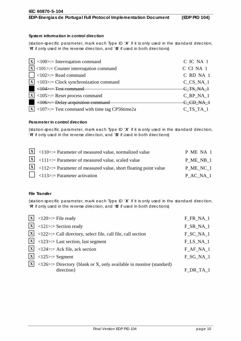
System information in control direction
(station-specific parameter, mark each Type ID ‘X’ if it is only used in the standard direction, ‘R’ if only used in the reverse direction, and ‘B’ if used in both directions)
Parameter in control direction
(station-specific parameter, mark each Type ID ‘X’ if it is only used in the standard direction, ‘R’ if only used in the reverse direction, and ‘B’ if used in both directions)
File Transfer
(station-specific parameter, mark each Type ID ‘X’ if it is only used in the standard direction, ‘R’ if only used in the reverse direction, and ‘B’ if used in both directions)
<100>:=<101>:= Counter interrogation command C CI NA 1<102>:= Read command C RD NA 1<103>:= Clock synchronization command C_CS_NA_1<104>:= Test command C_TS_NA_1<105>:= Reset process command C_RP_NA_1 <106>:= Delay acquisition command C_CD_NA_1 <107>:= Test command with time tag CP56time2a C_TS_TA_1
<110>:= Parameter of measured value, normalized value P ME NA 1
<111>:= Parameter of measured value, scaled value P_ME_NB_1 <112>:= Parameter of measured value, short floating point value P_ME_NC_1 <113>:= Parameter activation P_AC_NA_1
<120>:= File ready F_FR_NA_1
<121>:= Section ready F_SR_NA_1 <122>:= Call directory, select file, call file, call section F_SC_NA_1 <123>:= Last section, last segment F_LS_NA_1 <124>:= Ack file, ack section F_AF_NA_1 <125>:= Segment F_SG_NA_1 <126>:= Directory {blank or X, only available in monitor (standard)
direction} F_DR_TA_1
X
X
X
X
X
X
X
X
X
X X X X X X
<100>:= Interrogation command C IC NA 1
IEC 60870-5-104 EDP-Energias de Portugal Full Protocol Implementation Document (EDP PID 104)
Final Version EDP PID 104 page 11
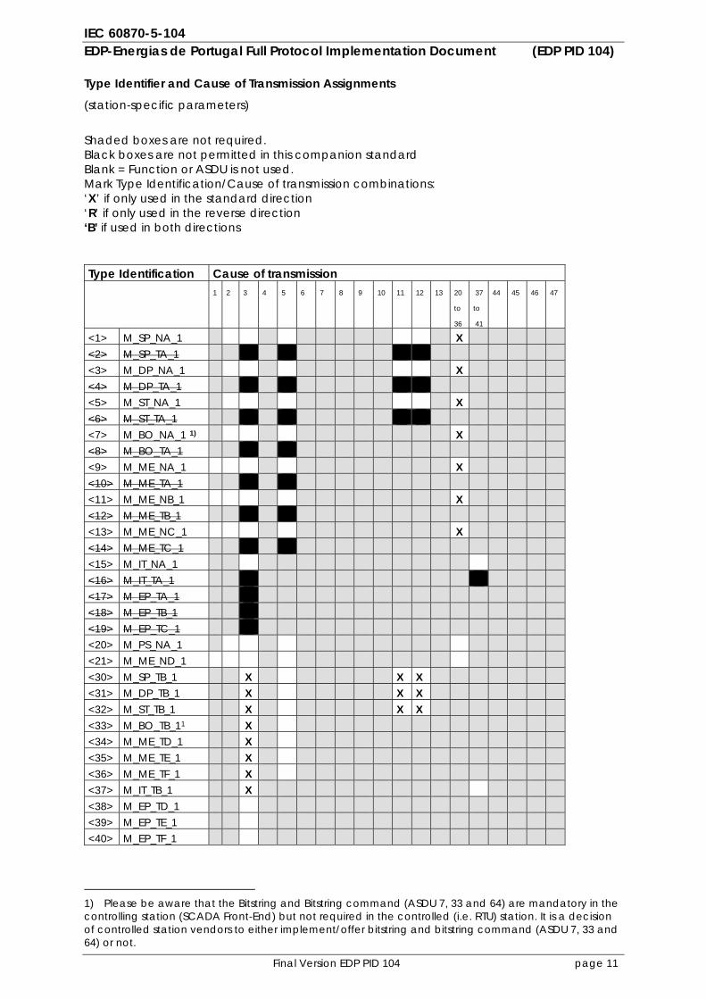
Type Identifier and Cause of Transmission Assignments
(station-specific parameters)
Shaded boxes are not required. Black boxes are not permitted in this companion standard Blank = Function or ASDU is not used. Mark Type Identification/Cause of transmission combinations: ‘X’ if only used in the standard direction ‘R’ if only used in the reverse direction ‘B’ if used in both directions Type Identification Cause of transmission 1 2 3 4 5 6 7 8 9 10 11 12 13 20
to
36
37
to
41
44 45 46 47
<1> M_SP_NA_1 X <2> M_SP_TA_1 <3> M_DP_NA_1 X <4> M_DP_TA_1 <5> M_ST_NA_1 X <6> M_ST_TA_1 <7> M_BO_NA_1 1) X <8> M_BO_TA_1 <9> M_ME_NA_1 X <10> M_ME_TA_1 <11> M_ME_NB_1 X <12> M_ME_TB_1 <13> M_ME_NC_1 X <14> M_ME_TC_1 <15> M_IT_NA_1 <16> M_IT_TA_1 <17> M_EP_TA_1 <18> M_EP_TB_1 <19> M_EP_TC_1 <20> M_PS_NA_1 <21> M_ME_ND_1 <30> M_SP_TB_1 X X X <31> M_DP_TB_1 X X X <32> M_ST_TB_1 X X X <33> M_BO_TB_11 X <34> M_ME_TD_1 X <35> M_ME_TE_1 X <36> M_ME_TF_1 X <37> M_IT_TB_1 X <38> M_EP_TD_1 <39> M_EP_TE_1 <40> M_EP_TF_1
1) Please be aware that the Bitstring and Bitstring command (ASDU 7, 33 and 64) are mandatory in the controlling station (SCADA Front-End) but not required in the controlled (i.e. RTU) station. It is a decision of controlled station vendors to either implement/offer bitstring and bitstring command (ASDU 7, 33 and 64) or not.
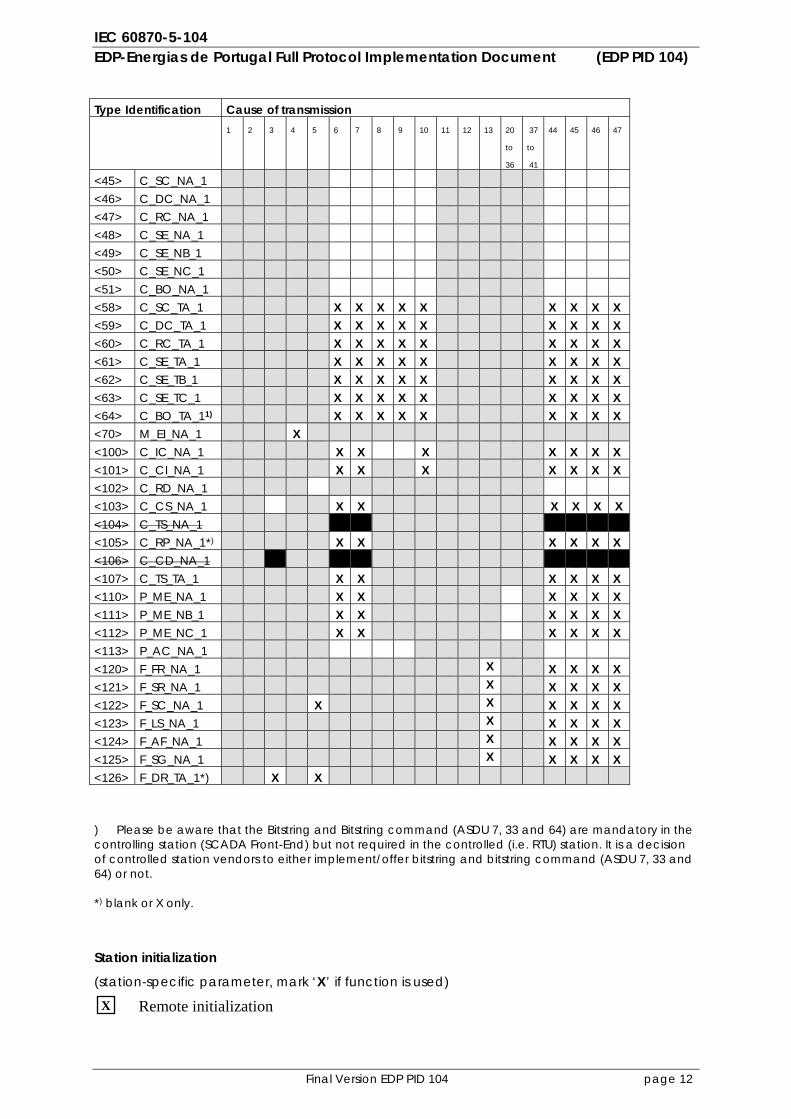
IEC 60870-5-104 EDP-Energias de Portugal Full Protocol Implementation Document (EDP PID 104)
Final Version EDP PID 104 page 12
Type Identification Cause of transmission 1 2 3 4 5 6 7 8 9 10 11 12 13 20
to
36
37
to
41
44 45 46 47
<45> C_SC_NA_1 <46> C_DC_NA_1 <47> C_RC_NA_1 <48> C_SE_NA_1 <49> C_SE_NB_1 <50> C_SE_NC_1 <51> C_BO_NA_1 <58> C_SC_TA_1 X X X X X X X X X <59> C_DC_TA_1 X X X X X X X X X <60> C_RC_TA_1 X X X X X X X X X <61> C_SE_TA_1 X X X X X X X X X <62> C_SE_TB_1 X X X X X X X X X <63> C_SE_TC_1 X X X X X X X X X <64> C_BO_TA_11) X X X X X X X X X <70> M_EI_NA_1 X <100> C_IC_NA_1 X X X X X X X <101> C_CI_NA_1 X X X X X X X <102> C_RD_NA_1 <103> C_CS_NA_1 X X X X X X <104> C_TS_NA_1 <105> C_RP_NA_1*) X X X X X X <106> C_CD_NA_1 <107> C_TS_TA_1 X X X X X X <110> P_ME_NA_1 X X X X X X <111> P_ME_NB_1 X X X X X X <112> P_ME_NC_1 X X X X X X <113> P_AC_NA_1 <120> F_FR_NA_1 X X X X X <121> F_SR_NA_1 X X X X X <122> F_SC_NA_1 X X X X X X <123> F_LS_NA_1 X X X X X <124> F_AF_NA_1 X X X X X <125> F_SG_NA_1 X X X X X <126> F_DR_TA_1*) X X ) Please be aware that the Bitstring and Bitstring command (ASDU 7, 33 and 64) are mandatory in the controlling station (SCADA Front-End) but not required in the controlled (i.e. RTU) station. It is a decision of controlled station vendors to either implement/offer bitstring and bitstring command (ASDU 7, 33 and 64) or not. *) blank or X only. Station initialization
(station-specific parameter, mark ‘X’ if function is used)
Remote initialization X
IEC 60870-5-104 EDP-Energias de Portugal Full Protocol Implementation Document (EDP PID 104)
Final Version EDP PID 104 page 13
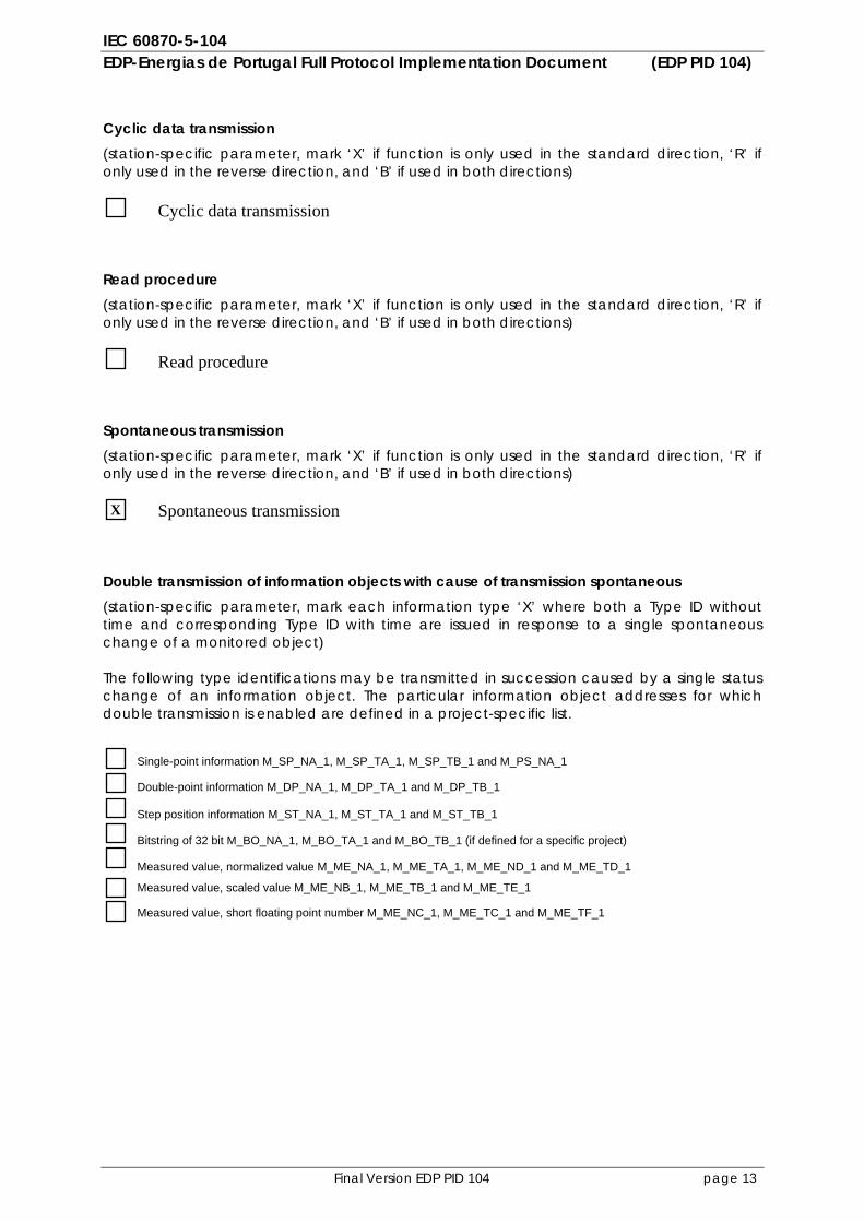
Cyclic data transmission (station-specific parameter, mark ‘X’ if function is only used in the standard direction, ‘R’ if only used in the reverse direction, and ‘B’ if used in both directions) Read procedure (station-specific parameter, mark ‘X’ if function is only used in the standard direction, ‘R’ if only used in the reverse direction, and ‘B’ if used in both directions) Spontaneous transmission (station-specific parameter, mark ‘X’ if function is only used in the standard direction, ‘R’ if only used in the reverse direction, and ‘B’ if used in both directions) Double transmission of information objects with cause of transmission spontaneous (station-specific parameter, mark each information type ‘X’ where both a Type ID without time and corresponding Type ID with time are issued in response to a single spontaneous change of a monitored object) The following type identifications may be transmitted in succession caused by a single status change of an information object. The particular information object addresses for which double transmission is enabled are defined in a project-specific list.
Single-point information M_SP_NA_1, M_SP_TA_1, M_SP_TB_1 and M_PS_NA_1
Double-point information M_DP_NA_1, M_DP_TA_1 and M_DP_TB_1
Step position information M_ST_NA_1, M_ST_TA_1 and M_ST_TB_1
Bitstring of 32 bit M_BO_NA_1, M_BO_TA_1 and M_BO_TB_1 (if defined for a specific project)
Measured value, normalized value M_ME_NA_1, M_ME_TA_1, M_ME_ND_1 and M_ME_TD_1
Measured value, scaled value M_ME_NB_1, M_ME_TB_1 and M_ME_TE_1
Measured value, short floating point number M_ME_NC_1, M_ME_TC_1 and M_ME_TF_1
Cyclic data transmission
Read procedure
Spontaneous transmission X
IEC 60870-5-104 EDP-Energias de Portugal Full Protocol Implementation Document (EDP PID 104)
Final Version EDP PID 104 page 14
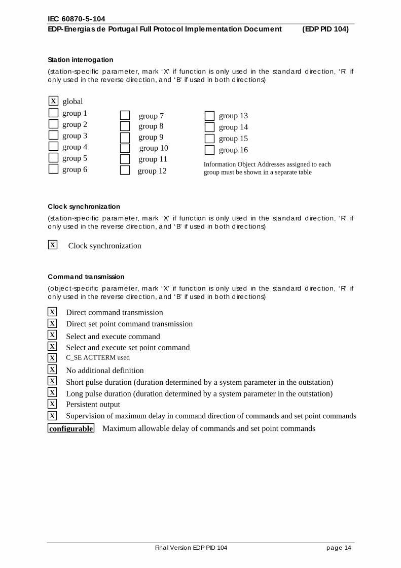
Station interrogation (station-specific parameter, mark ‘X’ if function is only used in the standard direction, ‘R’ if only used in the reverse direction, and ‘B’ if used in both directions)
Clock synchronization (station-specific parameter, mark ‘X’ if function is only used in the standard direction, ‘R’ if only used in the reverse direction, and ‘B’ if used in both directions) Command transmission (object-specific parameter, mark ‘X’ if function is only used in the standard direction, ‘R’ if only used in the reverse direction, and ‘B’ if used in both directions)
global
group 7 group 13group 1 group 8 group 14group 2 group 9 group 15group 3 group 10 group 16group 4 group 11group 5 group 12group 6
Information Object Addresses assigned to each group must be shown in a separate table
Clock synchronization
Direct command transmission Direct set point command transmission Select and execute command Select and execute set point commandC_SE ACTTERM used
No additional definition Short pulse duration (duration determined by a system parameter in the outstation)
Persistent output Long pulse duration (duration determined by a system parameter in the outstation)
X
X
X
X
X
X
X
X
X
X
X
Supervision of maximum delay in command direction of commands and set point commands X
Maximum allowable delay of commands and set point commands configurable
IEC 60870-5-104 EDP-Energias de Portugal Full Protocol Implementation Document (EDP PID 104)
Final Version EDP PID 104 page 15
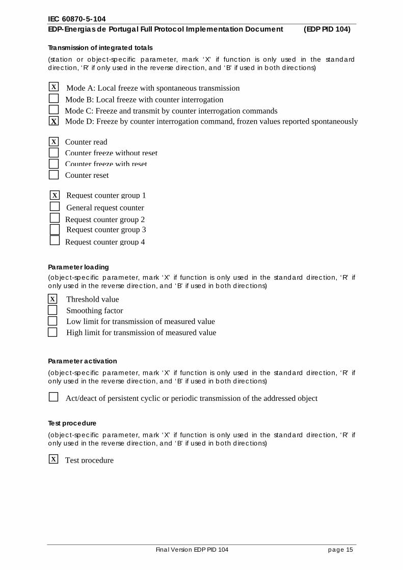
Transmission of integrated totals (station or object-specific parameter, mark ‘X’ if function is only used in the standard direction, ‘R’ if only used in the reverse direction, and ‘B’ if used in both directions) Parameter loading (object-specific parameter, mark ‘X’ if function is only used in the standard direction, ‘R’ if only used in the reverse direction, and ‘B’ if used in both directions) Parameter activation (object-specific parameter, mark ‘X’ if function is only used in the standard direction, ‘R’ if only used in the reverse direction, and ‘B’ if used in both directions) Test procedure (object-specific parameter, mark ‘X’ if function is only used in the standard direction, ‘R’ if only used in the reverse direction, and ‘B’ if used in both directions)
Counter read Counter freeze without resetCounter freeze with resetCounter reset
General request counter Request counter group 1
Request counter group 3 Request counter group 2
Request counter group 4
Threshold valueSmoothing factor Low limit for transmission of measured valueHigh limit for transmission of measured value
Act/deact of persistent cyclic or periodic transmission of the addressed object
X
X
X
Mode A: Local freeze with spontaneous transmission Mode B: Local freeze with counter interrogation Mode C: Freeze and transmit by counter interrogation commandsMode D: Freeze by counter interrogation command, frozen values reported spontaneously
X
X
Test procedure X
IEC 60870-5-104 EDP-Energias de Portugal Full Protocol Implementation Document (EDP PID 104)
Final Version EDP PID 104 page 16
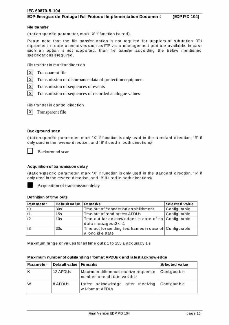
File transfer (station-specific parameter, mark ‘X’ if function is used).
Please note that the file transfer option is not required for suppliers of substation RTU equipment in case alternatives such as FTP via a management port are available. In case such an option is not supported, than file transfer according the below mentioned specifications is required. File transfer in monitor direction
File transfer in control direction
Background scan (station-specific parameter, mark ‘X’ if function is only used in the standard direction, ‘R’ if only used in the reverse direction, and ‘B’ if used in both directions) Acquisition of transmission delay (station-specific parameter, mark ‘X’ if function is only used in the standard direction, ‘R’ if only used in the reverse direction, and ‘B’ if used in both directions) Definition of time outs Parameter Default value Remarks Selected value t0 30s Time out of connection establishment Configurable t1 15s Time out of send or test APDUs Configurable t2 10s Time out for acknowledges in case of no
data messages t2 < t1 Configurable
t3 20s Time out for sending test frames in case of a long idle state
Configurable
Maximum range of values for all time outs: 1 to 255 s, accuracy 1 s
Maximum number of outstanding I format APDUs k and latest acknowledge
Parameter Default value Remarks Selected value
K 12 APDUs Maximum difference receive sequence number to send state variable
Configurable
W 8 APDUs Latest acknowledge after receiving w I-format APDUs
Configurable
Transparent file
Background scan
Acquisition of transmission delay
X
Transparent file X
Transmission of disturbance data of protection equipmentX
Transmission of sequences of events X
Transmission of sequences of recorded analogue values X
IEC 60870-5-104 EDP-Energias de Portugal Full Protocol Implementation Document (EDP PID 104)
Final Version EDP PID 104 page 17
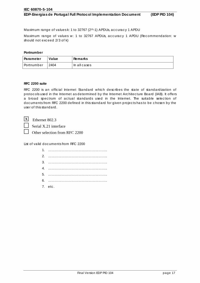
Maximum range of values k: 1 to 32767 (215-1) APDUs, accuracy 1 APDU
Maximum range of values w: 1 to 32767 APDUs, accuracy 1 APDU (Recommendation: w should not exceed 2/3 of k)
Portnumber
Parameter Value Remarks
Portnumber 2404 In all cases
RFC 2200 suite
RFC 2200 is an official Internet Standard which describes the state of standardization of protocols used in the Internet as determined by the Internet Architecture Board (IAB). It offers a broad spectrum of actual standards used in the Internet. The suitable selection of documents from RFC 2200 defined in this standard for given projects has to be chosen by the user of this standard.
List of valid documents from RFC 2200
1. ……………………………………………..
2. ……………………………………………..
3. ……………………………………………..
4. ……………………………………………..
5. ……………………………………………..
6. ……………………………………………..
7. etc.
Ethernet 802.3 Serial X.21 interface Other selection from RFC 2200
X
IEC 60870-5-104 EDP-Energias de Portugal Full Protocol Implementation Document (EDP PID 104)
Final Version EDP PID 104 page 18
3 PROTOCOL IMPLEMENTATION EXTRA INFORMATION FOR TESTING
3.1 Communication procedures
Table 3.1 shows a list of the basic communication procedures (basic application functions) that are applicable for EDP-Energias de Portugal. Table 3.1 Basic Application Functions: 1. Station initialisation 2. Acquisition of events 3. General Interrogation 4. Clock synchronisation 5. Command transmission 6. Transmission of integrated totals 7. Parameter loading 8. Test procedure 9. File transfer These application functions are further described in the subsequent sections.
3.1.1 Station initialization procedure
The controlling station always performs connection establishment. In case a TCP/IP connection is established, a stopped CS104 connection is created. In order to start data exchange the Controlling station will send a Start DT ack. After the controlled station has confirmed the Start DT by sending a Start DT confirmation an active CS104 connection is established. After a Start DT procedure the controlling station needs to start in all cases the General Interrogation procedure by sending a general interrogation command (ASDU 100). In case the controlled station was restarted or a power shutdown occurred the controlled station will send an End of Initialization (ASDU 70) in order to update the controlling station. The controlling station can send a Reset process command (ASDU 105) to the controlled station to restart the controlled station. This is not an automatic function and shall only be initiated via manual interaction. The Reset process command confirmation is not required to be sent by the controlled station to the controlling station since the TCP connection may already be closed. As a result of the Reset process command the controlled station will close the CS104 connection by sending a close call to its TCP. When the TCP connection is closed the controlled station will be restarted. Then the controlling station tries to connect the controlled station by giving cyclic active opens to its TCP.
3.1.2 Acquisition of events procedure
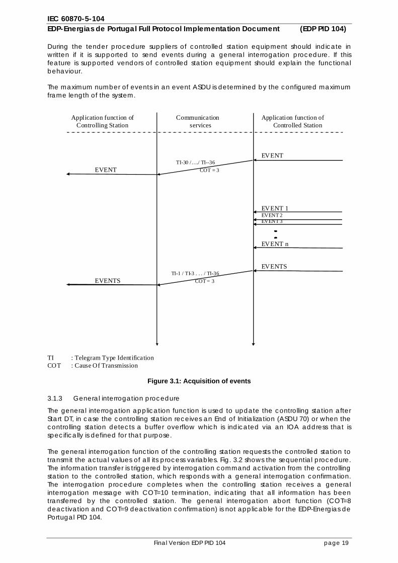
Events occur spontaneously at the application level of the local (controlled) station. The local process requires an event buffer to collect events that may appear faster than their transmission to the remote (controlling) station can be accomplished. Fig. 3.1 shows the sequential procedure for event acquisition. Events that arrive in the controlled station are transmitted to the controlling station as soon as possible after they appear. Events that arrive faster than transmission to the controlling station can be accomplished are buffered in the controlled station. The EDP-Energias de Portugal PID104 specifies that for event transmission only events with time tag are transmitted to the controlling station. The Cause of Transmission can, due to the initial reason of the event be, either COT=3 spontaneous, COT=11 remote command or COT=12 local command.
IEC 60870-5-104 EDP-Energias de Portugal Full Protocol Implementation Document (EDP PID 104)
Final Version EDP PID 104 page 19
During the tender procedure suppliers of controlled station equipment should indicate in written if it is supported to send events during a general interrogation procedure. If this feature is supported vendors of controlled station equipment should explain the functional behaviour. The maximum number of events in an event ASDU is determined by the configured maximum frame length of the system. Application function of Communication Application function of
Controlling Station services Controlled Station
EVENT TI-30 /…./ TI--36 EVENT COT = 3 EVENT 1 EVENT 2 EVENT 3 EVENT n EVENTS TI-1 / TI-3 . . . / TI-36 EVENTS COT = 3 TI : Telegram Type Identifica tion COT : Cause Of Transmission
Figure 3.1: Acquisition of events
3.1.3 General interrogation procedure
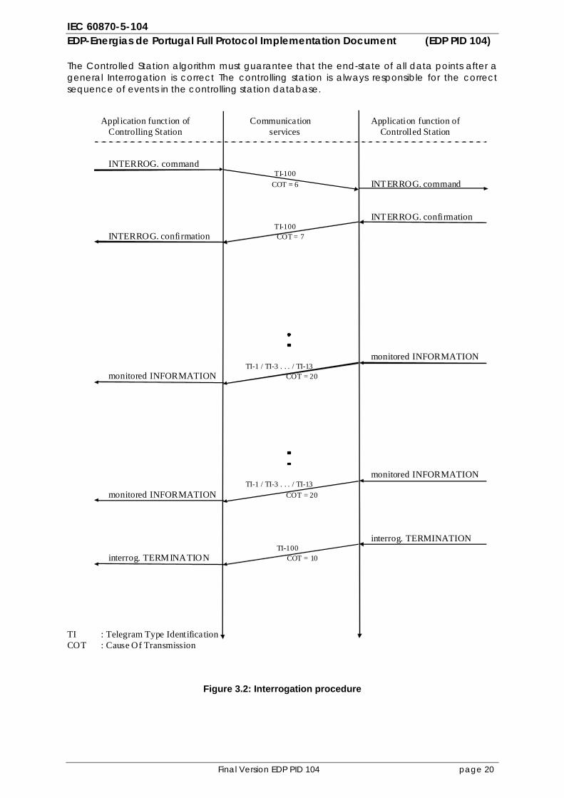
The general interrogation application function is used to update the controlling station after Start DT, in case the controlling station receives an End of Initialization (ASDU 70) or when the controlling station detects a buffer overflow which is indicated via an IOA address that is specifically is defined for that purpose. The general interrogation function of the controlling station requests the controlled station to transmit the actual values of all its process variables. Fig. 3.2 shows the sequential procedure. The information transfer is triggered by interrogation command activation from the controlling station to the controlled station, which responds with a general interrogation confirmation. The interrogation procedure completes when the controlling station receives a general interrogation message with COT=10 termination, indicating that all information has been transferred by the controlled station. The general interrogation abort function (COT=8 deactivation and COT=9 deactivation confirmation) is not applicable for the EDP-Energias de Portugal PID 104.
IEC 60870-5-104 EDP-Energias de Portugal Full Protocol Implementation Document (EDP PID 104)
Final Version EDP PID 104 page 20
The Controlled Station algorithm must guarantee that the end-state of all data points after a general Interrogation is correct The controlling station is always responsible for the correct sequence of events in the controlling station database.
Application function of Communication Application function of Controlling Station services Controlled Station
INTERROG. command TI-100
COT = 6 INTERROG. command INTERROG. confirmation TI-100 INTERROG. confirmation COT = 7 monitored INFORMATION TI-1 / TI-3 . . . / TI-13 monitored INFORMATION COT = 20 monitored INFORMATION TI-1 / TI-3 . . . / TI-13 monitored INFORMATION COT = 20 interrog. TERMINATION TI-100 interrog. TERMINATION COT = 10 TI : Telegram Type Identification COT : Cause Of Transmission
Figure 3.2: Interrogation procedure
IEC 60870-5-104 EDP-Energias de Portugal Full Protocol Implementation Document (EDP PID 104)
Final Version EDP PID 104 page 21
3.1.4 Clock synchronisation procedure
The clock synchronisation command is used to synchronise the time in the controlled station with the time in the controlling station. Because of a flexible time delay in the network, EDP-Energias de Portugal requires multiple options how to synchronize the clocks in the controlled stations. The following technologies are defined: 1. Via an external GPS receiver 2. Via the SNTP protocol 3. Via the CS104 clock synchronisation command (ASDU 103)
It is required that the controlling station (Front-End) supports clock synchronisation via CS104 using ASDU 103. For controlled stations that are able to receive an external clock (such as GPS or SNTP) and an external clock is available at the locations the controlled stations are installed, the clock synchronization command via CS104 (ASDU 103) is not required. In case the vendor of the controlled station supports time synchronization via an external clock, it is the responsibility of the vendor to indicate which time synchronization options are supported and to verify during the tender process if an external clock will be available at the locations the controlled stations will be installed. The controlling station will send a clock synchronization command on every link after Start DT and on a configurable time interval. The time interval should be configurable with a minimum range of once every hour and a maximum of once every 24 hours.
3.1.5 Command transmission procedure
3.1.5.1 General
Commands are used in telecontrol systems to cause a change of state of operational equipment. The EDP-Energias de Portugal PID104 requires two standard procedures for command transmission: 1. Select and execute command 2. Direct command Select/execute and direct commands may be assigned individually and independently to each commanded object (IOA) in the controlled station (by system configuration parameters in the controlling station). The EDP-Energias de Portugal PID104 requires to only use commands with time tag format CP56Time2a.
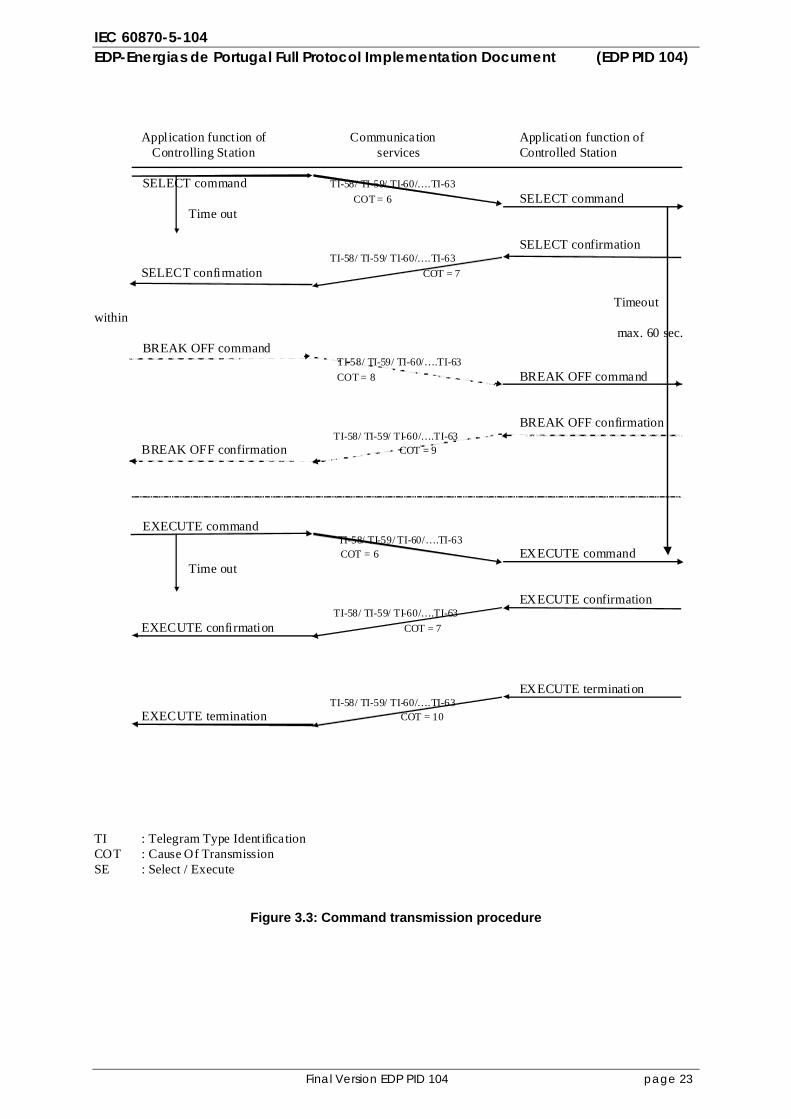
3.1.5.2 Select and execute command
The select and execute command is used by the controlling station to: - Prepare for a specific control operation in the controlled station - Check that the control operation has been prepared. - Execute the prepared operation if checks are positive The sequential procedure for a select and execute command is shown in fig. 3.3. The controlling station sends a SELECT command message to the controlled station, which responds by a SELECT confirmation message if it is ready to accept the announced command. The time from the SELECT command to the SELECT confirmation is controlled by a configurable time-out interval in the controlling station. A not successful select procedure may be deactivated by a "Break off” command. This command is transmitted by a BREAK OFF command message and the controlled station responds by a BREAK OFF confirmation message. The time between these messages is controlled by a timeout in the controlling station. A successful select procedure may be executed by an EXECUTE command message. The EXECUTE command message is sent to the controlled station, which responds by an EXECUTE confirmation message. The time from the EXECUTE command to the EXECUTE confirmation is controlled by a configurable time-out interval in the controlling station.
IEC 60870-5-104 EDP-Energias de Portugal Full Protocol Implementation Document (EDP PID 104)
Final Version EDP PID 104 page 22
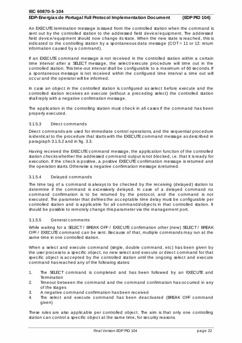
An EXECUTE termination message is issued from the controlled station when the command is sent out by the controlled station to the addressed field device/equipment. The addressed field device/equipment should now change its state. When the new state is reached, this is indicated to the controlling station by a spontaneous data message (COT = 11 or 12: return information caused by a command). If an EXECUTE command message is not received in the controlled station within a certain time interval after a SELECT message, the select/execute procedure will time out in the controlled station. This time-out interval shall be configurable to a maximum of 60 seconds. If a spontaneous message is not received within the configured time interval a time out will occur and the operator will be informed. In case an object in the controlled station is configured as select before execute and the controlled station receives an execute (without a preceding select) the controlled station shall reply with a negative confirmation message. The application in the controlling station must check in all cases if the command has been properly executed.
3.1.5.3 Direct commands
Direct commands are used for immediate control operations, and the sequential procedure is identical to the procedure that starts with the EXECUTE command message as described in paragraph 3.1.5.2 and in fig. 3.3. Having received the EXECUTE command message, the application function of the controlled station checks whether the addressed command output is not blocked, i.e. that it is ready for execution. If the check is positive, a positive EXECUTE confirmation message is returned and the operation starts. Otherwise a negative confirmation message is returned.
3.1.5.4 Delayed commands
The time tag of a command is always to be checked by the receiving (delayed) station to determine if the command is excessively delayed. In case of a delayed command no command confirmation is to be returned by the protocol, and the command is not executed. The parameter that defines the acceptable time delay must be configurable per controlled station and is applicable for all commands/objects in that controlled station. It should be possible to remotely change this parameter via the management port.
3.1.5.5 General comments
While waiting for a SELECT / BREAK OFF / EXECUTE confirmation other (new) SELECT / BREAK OFF / EXECUTE command can be sent. Because of that, multiple commands may run at the same time in one controlled station. When a select and execute command (single, double command, etc) has been given by the user process to a specific object, no new select and execute or direct command for that specific object is accepted by the controlled station until the ongoing select and execute command has reached any of the following states: 1. The SELECT command is completed and has been followed by an EXECUTE and
Termination 2. Timeout between the command and the command confirmation has occurred in any
of the stages 3. A negative command confirmation has been received 4. The select and execute command has been deactivated (BREAK OFF command
given) These rules are also applicable per controlled object. The aim is that only one controlling station can control a specific object at the same time, for security reasons.
IEC 60870-5-104 EDP-Energias de Portugal Full Protocol Implementation Document (EDP PID 104)
Final Version EDP PID 104 page 23
Application function of Communication Application function of
Controlling Station services Controlled Station
SELECT command TI-58/ TI-59/ TI-60/….TI-63 COT = 6 SELECT command
Time out SELECT confirmation TI-58/ TI-59/ TI-60/….TI-63 SELECT confirmation COT = 7 Timeout within max. 60 sec.
BREAK OFF command TI-58/ TI-59/ TI-60/….TI-63
COT = 8 BREAK OFF command BREAK OFF confirmation TI-58/ TI-59/ TI-60/….TI-63 BREAK OFF confirmation COT = 9
EXECUTE command TI-58/ TI-59/ TI-60/….TI-63
COT = 6 EXECUTE command Time out EXECUTE confirmation TI-58/ TI-59/ TI-60/….TI-63 EXECUTE confirmation COT = 7 EXECUTE termination TI-58/ TI-59/ TI-60/….TI-63 EXECUTE termination COT = 10 TI : Telegram Type Identifica tion COT : Cause Of Transmission SE : Select / Execute
Figure 3.3: Command transmission procedure
IEC 60870-5-104 EDP-Energias de Portugal Full Protocol Implementation Document (EDP PID 104)
Final Version EDP PID 104 page 24
3.1.6 Integrated totals procedure
Integrated totals will be used by EDP-Energias de Portugal to receive counter information. This counter information can i.e. be used to exchange counter information from the controlled station to the controlling station about the amount of times a switch moved position. EDP-Energias de Portugal requires that integrated totals can be sent with Mode A and D. EDP-Energias de Portugal requires that counters are sent with Mode A periodically via COT=3. The parameter to define the time interval should be configurable with a minimum range of each hour and a maximum range of one a month. For every counter the time interval should be configured independently. In addition EDP-Energias de Portugal requires the possibility to request counters via Mode D. An operator will trigger the controlling station to send a counter request (ASDU 101) to the applicable controlled station. The controlled station will be triggered to send all counter information spontaneous via COT=3.
3.1.7 Parameter load procedure
EDP-Energias de Portugal is going to use parameter load in order to remotely change parameters i.e. such as protection settings. Parameters are loaded and activated in two steps. Step 1 is to first load the parameters to the controlled station (ASDU 110-112). Afterwards (step 2) the loaded parameters are activated via an object address specifically defined for this purpose. The controlling station will send to the controlled station the parameter load command with COT=6. When the controlled station receives the parameter load command, the controlled station first checks if the parameter can be loaded i.e. if the parameter value is in the acceptable range. If all checks have been performed positively, the controlled station will send the parameter load activation confirmation (COT=7). All parameters can thus first be loaded to the controlled station. By doing so, the controlling station can verify if all individual loaded parameters can be activated. If all parameters have been send to the controlled station, and a positive confirmation was received for all parameters the controlling station can decide to activate all previously loaded parameters at the same time. A parameter command (ASDU 110-112) with a specific IOA address will then be sent to the controlled station in order to activate all previously loaded parameters. By sending the parameter load activation confirmation (COT=7) for this object address the controlling station will be informed that all loaded parameters have been activated. Both the controlling and controlled station can have two parameters values for one object, the actual parameter and the loaded but not yet activated parameter. When sending the parameter load activation confirmation in step 1 the controlled station informs the controlling station that the parameter was successfully loaded. In case the parameter load activation confirmation for the specific object address was received the controlling station knows that the previously loaded parameters in step 1 are successfully activated and are the actual loaded parameter. By using this information2, the controlling station can keep track of the actual and loaded parameters.
3.1.8 Test procedure
The test command (ASDU 105) is used by EDP-Energias de Portugal to test end-to-end the communication chain. The testcommand is send automatically by the controlling station via a configurable time interval. This time interval should be configurable per controlled station. The time interval should be configurable with a mimimum range every minute up to once every 24 hours.
2) Both parameters (step 1 and step 2) in the parameter confirmations shall be sent as soon as they are accepted / changed in the controlled station to the controlling station so the operator is aware of the parameters that he is going to activate in step 2 and/or are activated.
IEC 60870-5-104 EDP-Energias de Portugal Full Protocol Implementation Document (EDP PID 104)
Final Version EDP PID 104 page 25
At 30/31 January 2003 TC57 WG03 has decided that the TCS response must match the request. The requesting station may choose any TCS value. The time in the response must exactly match the time in the request. In case the testcommand fails a message is provided to the operator via the HMI indicating that the testcommand has failed and that the maintenance department should be informed.
3.1.9 File transfer procedure
As defined in chapter 2 of this PID, the PICS, all file transfer functions in both monitor and control direction are required. File transfer in control direction can be used to send (new) configuration files to the controlled station. An automatic function in the controlled station can then load the new configuration to the RTU. This automatic function is not described in this PID and should be defined per project / vendor. Please be aware that file transfer via CS104 is required for: 1. The controlling station implementation (SCADA/Front-End) 2. The controlled stations (i.e. substation RTU’s) in case no other file transfer method (i.e. FTP)
is supported. If other file transfer methods (other than file transfer via CS104 using ASDU 120-126) are available i.e. FTP, then file transfer via CS104 (ASDU 120-126) is not required. EDP-Energias de Portugal prefers to use file transfer via FTP (and not via CS104) via a management port. The management port can either be a second physical (RJ45) interface on the device, or the same physical interface as the CS104 interface and differentiated by TCP port numbers. If file transfer via CS104 is used, please note that file transfer should have the lowest priority.
3.2 Functions
This paragraph contains additional information about functionality that is not necessarily covered by the standard. However, the functions described in this chapter are functions needed within EDP-Energias de Portugal and should thus be implemented as described in this chapter.
3.2.1 General
It may never appear that a CS104 protocol link goes in a stop/halt/abort state as a result of a not correct received or erroneous data-frame/quality flag etc. The device should log the event with additional relevant data in the system event list for maintenance engineers. In the controlled station it could be integrated a lot of system events. If the system events should be transferred to the controlling station it has to be done with standard ASDUs.
3.2.2 Time tags
Within EDP-Energias de Portugal CS104 events (COT=3, 11 and 12) and commands are always sent with time tag. During the summertime period, EDP-Energias de Portugal uses the summertime. For this reason the summertime bit within the CP56Time2a timetag will be used. It is the responsibility of the vendor that there will be no mismatch in the time tags (i.e. at summer/wintertime changes, etc.) when displaying time tagged data, exchange time tagged data and storing this time tagged data.
3.2.3 Quality bits
The protocol implementations must always support all quality bits. Vendors of stations that issue monitoring data should implement the quality bits in the application to a largest possible extent, in accordance with the definitions. Vendors of stations that receive monitoring data should submit to the project how the quality bits are utilised (e.g. logged or flagged) in the application.
IEC 60870-5-104 EDP-Energias de Portugal Full Protocol Implementation Document (EDP PID 104)
Final Version EDP PID 104 page 26
3.2.4 Transfer of data from Controlled Station to Controlling Station
In the EDP-Energias de Portugal PID 104 Indications, Measurands and Pulse Counters are transferred from Controlled Station to Controlling Station on event basis. Events, caused by a trip or a (remote) command, will have higher priority than General Interrogation. Events can interrupt an ongoing General Interrogation. The Controlled Station algorithm must guarantee that the end-state of all data points after a general Interrogation is correct.
3.2.5 Event Buffers
The buffer size for CS104 frames is not defined in this PID however it must be configurable. It is required that suppliers of RTU equipment shall clearly indicate in the tender procedure the maximum size of the event buffer. To prevent consecutive overflow EDP-Energias de Portugal requires from the vendor of the RTU that after a buffer overflow has been sent, the buffer has been empty for at least 50% of its capacity before the next buffer overflow indication will be sent. The RTU vendor shall describe in detail how the system prevents from sending consecutives buffer overflows if the transmission channel has problems. If a vendor has any other mechanism implemented to prevent sending consecutive buffer overflow indications, it is decided by EDP whether this can be accepted by EDP. In case a buffer overflow occurs the controlled station should be triggered to send an object, specifically configured for this purpose, to indicate to the controlling station that a buffer overflow has occurred. In addition to the above mentioned, the following rules apply: – For objects defined as a digital: Delete the newest event. – For objects configured as an analog: Delete the oldest event.
3.2.6 Security
The controlled station should only accept the establishment of a TCP/IP connection that is known in the controlled station. Therefore it must be possible to configure a list of IP addresses from Master stations (SCADA Front-Ends) that are allowed to establish a connection to.
3.3. Addressing
3.3.1 Portnumber
Every TCP address consists of an IP address and a port number. Every controlled equipment connected to the TCP-LAN has its individual IP address, while the standard port number for IEC 60870-5-104 is defined to be 2404, confirmed by IANA. The server (listener, controlled station) uses the port number 2404 in all cases, both for the listening port and the established connections. The client (connector, controlling station) is free to use ephemeral port numbers, e.g. as allocated by the client’s TCP/IP implementation.
3.3.2 Common Address of ASDU
The Common Address of ASDU (CAA) is common number used for all objects in one Controlled Station. In the case of EDP-Energias de Portugal, one controlled station will only have one CAA. Since every controlled station only has one CAA the EDP-Energias de Portugal PID104 specifies that the broadcast address for the Common address of ASDU (FFFF) is not used.
IEC 60870-5-104 EDP-Energias de Portugal Full Protocol Implementation Document (EDP PID 104)
Final Version EDP PID 104 page 27
3.3.3 Information Object Address
The Information Object Address is a number given to each data point or object within one controlled station.
3.3.4 Addressing rules
All the addresses can be set to any valid number taking into account that: the total address built together by the Common Address of ASDU and Information Object Address shall be a unique identifier for all data points (objects) for every logical link between a controlling- and a controlled station.
3.4 Test requirements
EDP-Energias de Portugal has defined a strict test approach, which is described in document 40630030-Consulting 07-0711 “EDP QA Phase II, Document 2 Suppliers Quality System Demands (ITP)”. This chapter, chapter 3.4 test requirements, describes the specific test criteria for the CS104 data communication interfaces in order to prove that the protocol implementation delivered by the vendors is according to the IEC standards and the EDP-Energias de Portugal PID104. The test criteria will consist of a: – Type (conformance) test – Special (FAT) test – Commisioning (SAT) test
3.4.1 Type (conformance) Test
EDP-Energias de Portugal requires all CS104 communication interfaces implemented in all delivered equipment to be type (conformance) tested and certified by an independent third party test institute. Protocol type (conformance) testing is the process of verifying that an CS104 implementation performs in accordance with the applicable documents as the IEC standard and the EDP-Energias de Portugal PID104. A manufacturer may claim: “my equipment conforms to standard ISO/IEC xxx-x ”. Type (conformance) testing enables such a claim to be investigated and assessed by an objective and independent third party test institute to establish its validity. The below mentioned requirements are applicable: – An objective and (vendor/supplier) independent third party test and certification
institute must perform the type (conformance) test. The test and certification institue will be organized according the international standard ISO.IEC17025. Besides this standard the test and certification organisation and the test procedures must follow a quality system such as ISO9001: 2000 or a comparable quality system. If requested EDP-Energias de Portugal can supply contact information of at least one independent test and certification institute.
– The type (conformance) test must be performed for all to be delivered types of controlling and controlled station protocol implementations.
– The type (conformance) test will be performed against type (conformance) test plans that, before the conformance test will be performed, need to be approved by EDP-Energias de Portugal. The type (conformance) test plans will be delivered by the third party test and certification institute.
– If necessary a retest must be done. When the test results are according the requirements the test and certification institute will issue an Attestation of Conformance.
– An Attestation of Conformance remains valid as long as the vendor guarantees that no changes in communication hard- and software have been made that can influence the certified protocol implementation. If changes have been made, a retest is mandatory to update the Attestation of Conformity and to assure conformance.

IEC 60870-5-104 EDP-Energias de Portugal Full Protocol Implementation Document (EDP PID 104)
Final Version EDP PID 104 page 28
A paper version of the Attestation of Conformance must be handed over to energies de Portugal. The supplier shall also provide the belonging test reports, model numbers, software and firmware references, etc. as necessary, to clearly identify the functionality covered by the protocol implementation. All this documents, information etc. must be handed over prior to the special (FAT) test.
3.4.2 Special (Factory Acceptance Test) Test
The vendor will adopt a flexible and cooperative attitude in order to identify and describe all required tests needed to perform a complete special (FAT) test. The special (FAT) test should be performed in a realistic test environment. The vendor will deliver an inspection test plan (ITP) that describes all tests as proposed by the vendor. It is in the power of EDP-Energias de Portugal to review this ITP and decide if additional tests in the ITP are needed, existing tests need to be re-described and how the test will be organized.
3.4.3 Commisioning (Site Acceptance Test) test
The vendor will adopt a flexible and cooperative attitude in order to identify and describe all required tests needed to perform a complete commissioning (SAT) test. The commissioning (SAT) test should be performed at location of EDP-Energias de Portugal integrated in the EDP-Energias de Portugal (test) environment. The vendor will deliver an inspection test plan (ITP) that describes all tests as proposed by the vendor. It is in the power of EDP-Energias de Portugal to review this ITP and decide if additional tests in the ITP are needed, existing tests need to be re-described and how the test will be organized.