Embed Size (px)
Citation preview
Tests with a Hybrid Bearing for a Flywheel Energy
Storage System
G. G. Sotelo*1, E. Rodrigues2, F. S. Costa2, J. G. Oliveira3, J.
de Santiago4, , R M Stephan2
1 Department of Electrical Engineering, Fluminense Federal University, Niteroi, Rio
de Janeiro, Brazil2 Department of Electrical Engineering, Rio de Janeiro Federal University, Rio de
Janeiro, Rio de Janeiro, Brazil3 Universidade Federal de Juiz de Fora, Cidade Universitaria Plataforma 5 Martelos,
CEP 36036-900, Juiz de Fora MG, Brazil4 Uppsala University, Angstrom Laboratory, 751 21, Uppsala, Sweden
E-mail: Corresponding author:[email protected]
Abstract. This paper describes the design and experimental test of a passive
magnetic bearing system composed by a Superconductor Magnetic Bearing (SMB) and
a Permanent Magnet Bearing (PMB). This bearing setup is part of a flywheel energy
storage system. The advantage of using a passive bearing system is that it offers low
friction without the need of a magnetic bearing controller, increasing the reliability
and decreasing the energy consumption. The first set of tests were quasi-static radial
and axial force measurements of the PMB operating alone and together with the SMB.
As the PMB is intrinsically unstable in one degree of freedom, the operation of the
SMB together with the PMB is necessary to stabilize the system. After that, dynamic
measurements were made for the SMB operating alone and together with the PMB.
The resonant speeds were identified and the bearing radial and axial forces were also
measured for the SMB and SMB + PMB operation. These results indicate that the
studied bearing set is technologically feasible to be used in flywheel energy storage
systems.
Keywords: Superconducting Bearing, Permanent Magnet Bearing, FESS.
1. Introduction
The generation, transmission and distribution of electrical energy changed the
industrial sector in the last century. Nevertheless, electrical energy storage is still a
challenge. There are several options, such as: batteries [1], fuel cells [2], supercapacitor
[3], SMES (Superconducting Magnetic Energy Storage) [4], FESS (Flywheel Enegy
Storage System) [5], thermal energy [6], compressed air [7], pumped hydro [8], etc. The
literature presents several papers comparing the different energy storage technologies
[9, 10, 11], each one having its specific application niche. Energy storage systems are
Tests with a Passive Hybrid Bearing Setup for a Flywheel Energy Storage System 2
classified according to their energy capacity, power rate, lifetime, availability factor, etc.
There is no dominant technology in the specic case of small and medium applications,
in the range of few square meters and less of one tonne. The focus of this paper is set
in this area.
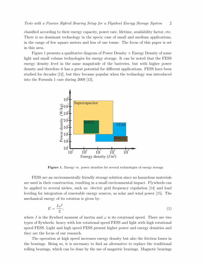
Figure 1 presents a qualitative diagram of Power Density × Energy Density of some
light and small volume technologies for energy storage. It can be noted that the FESS
energy density level in the same magnitude of the batteries, but with higher power
density and therefore it has a great potential for different applications. FESS have been
studied for decades [12], but they became popular when the technology was introduced
into the Formula 1 cars during 2009 [13].
107106 108 109
Energy density (J/m3)
Pow
er d
ensi
ty (
W/k
g)
101102103104105106107108
105
Supercapacitor
SMES
Battery
FESS
Figure 1. Energy vs. power densities for several technologies of energy storage.
FESS are an environmentally friendly storage solution since no hazardous materials
are used in their construction, resulting in a small environmental impact. Flywheels can
be applied to several niches, such as: electric grid frequency regulation [14] and load
leveling for integration of renewable energy sources, as solar and wind power [15]. The
mechanical energy of its rotation is given by:
E =Iω2
2, (1)
where I is the flywheel moment of inertia and ω is its rotational speed. There are two
types of flywheels: heavy with low rotational speed FESS and light with high rotational
speed FESS. Light and high speed FESS present higher power and energy densities and
they are the focus of our research.
The operation at high speed increases energy density but also the friction losses in
the bearings. Being so, it is necessary to find an alternative to replace the traditional
rolling bearings, which can be done by the use of magnetic bearings. Magnetic bearings
Tests with a Passive Hybrid Bearing Setup for a Flywheel Energy Storage System 3
can be classified into two major types: active magnetic bearing and passive magnetic
bearing. In the literature it is possible to find flywheels assembled with: mechanical
bearings [16], hybrid ceramic/magnetic bearings [17], active magnetic bearings [18],
and with Superconducting Magnetic Bearings (SMB)[5, 19, 20]. The active technology
requires accurate control of the current through the windings of electromagnets and
has already some industrial suppliers. An alternative passive magnet bearing set is
composed by a SMB and a Permanent Magnet Bearing (PMB). The SMBs present
different properties than rolling bearings and active bearings. They have lower force
density and require broader air gaps. SMBs present limitations concerning the weight
of the flywheel and the air gap required to motor/generator. The main advantage of
the PMB and SMB bearing set in relation with the active bearings is the low level of
energy consumption and reliability.
Since a completely passive PMB is not stable (as well known by Earnshaw
Theorem), and a bearing system using only SMB would be more expensive to build
and operate, the hybrid PMB-SMB configuration presents a good benefit cost relation.
In other words, the use of SMB allows the vertical stabilization of the PMB for the
bearing operation, while the SMB reduces the number of superconductors used into the
bearing and the power necessary to cooling the HTS material.
Flywheels with PMB and SMB bearings operating together were studied previously
by the group [14]. Prototypes of flywheels with PMB and SMB were also constructed
by other authors [21, 22] with some differences in the bearing topology (like a radial
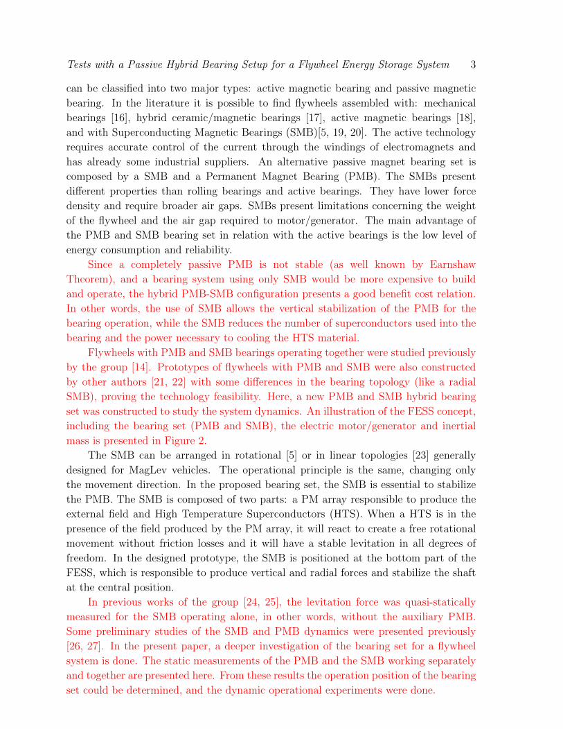
SMB), proving the technology feasibility. Here, a new PMB and SMB hybrid bearing
set was constructed to study the system dynamics. An illustration of the FESS concept,
including the bearing set (PMB and SMB), the electric motor/generator and inertial
mass is presented in Figure 2.
The SMB can be arranged in rotational [5] or in linear topologies [23] generally
designed for MagLev vehicles. The operational principle is the same, changing only
the movement direction. In the proposed bearing set, the SMB is essential to stabilize
the PMB. The SMB is composed of two parts: a PM array responsible to produce the
external field and High Temperature Superconductors (HTS). When a HTS is in the
presence of the field produced by the PM array, it will react to create a free rotational
movement without friction losses and it will have a stable levitation in all degrees of
freedom. In the designed prototype, the SMB is positioned at the bottom part of the
FESS, which is responsible to produce vertical and radial forces and stabilize the shaft
at the central position.
In previous works of the group [24, 25], the levitation force was quasi-statically
measured for the SMB operating alone, in other words, without the auxiliary PMB.
Some preliminary studies of the SMB and PMB dynamics were presented previously
[26, 27]. In the present paper, a deeper investigation of the bearing set for a flywheel
system is done. The static measurements of the PMB and the SMB working separately
and together are presented here. From these results the operation position of the bearing
set could be determined, and the dynamic operational experiments were done.
Tests with a Passive Hybrid Bearing Setup for a Flywheel Energy Storage System 4
Motor/Generator
Flywheel
PMB
SMB
Figure 2. Schematic of the FESS under development.
2. Methodology
2.1. Magnetic Bearing Set
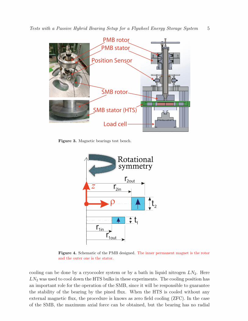
The experimental set up for the magnetic bearing tests is presented schematically
in Figure 3. The focus of these tests is to obtain the magnetic forces. The bearings are
tested separately so that the contribution of each bearing is identified. The flywheel
shaft and motor presented in Figure 3 are not included in the test. Details of the
bearings design are presented in the sequence.
2.2. Permanent Magnet Bearing
The upper bearing is a permanent magnet one, and it consists of two rings of axially
oriented permanent magnets. This bearing has a very simple construction, since it is
composed by two concentric permanent magnet rings, as presented in Figure 4 and
Table 1. Some experimental and simulated preliminary results of this PMB, studied
without the SMB, were presented in [26, 27]. Some experiments of the static and
dynamic tests to characterize the lower passive magnetic bearing will be reported in the
results section.
2.3. Superconducting Magnetic Bearing
High Temperature Superconductors (HTS) need to be cooled under its critical
temperature to present the diamagnetic effect. Also, HTS bulks are doped with
impurities to avoid movement of the pined flux. In the SMB, the superconductor bulk
Tests with a Passive Hybrid Bearing Setup for a Flywheel Energy Storage System 5
PMB rotor
Position Sensor
SMB stator (HTS)
Load cell
SMB rotor
PMB stator
Figure 3. Magnetic bearings test bench.
r1inr1out
r2in
r2out
t1
t2
Rotationalsymmetry
ρ
z
Figure 4. Schematic of the PMB designed. The inner permanent magnet is the rotor
and the outer one is the stator.
cooling can be done by a cryocooler system or by a bath in liquid nitrogen LN2. Here
LN2 was used to cool down the HTS bulks in these experiments. The cooling position has
an important role for the operation of the SMB, since it will be responsible to guarantee
the stability of the bearing by the pined flux. When the HTS is cooled without any
external magnetic flux, the procedure is knows as zero field cooling (ZFC). In the case
of the SMB, the maximum axial force can be obtained, but the bearing has no radial
Tests with a Passive Hybrid Bearing Setup for a Flywheel Energy Storage System 6
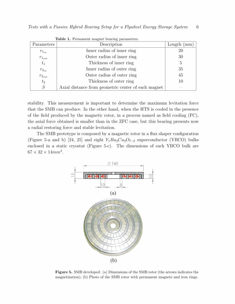
Table 1. Permanent magnet bearing parameters.
Parameters Description Length (mm)
r1in Inner radius of inner ring 20
r1out Outer radius of inner ring 30
t1 Thickness of inner ring 5
r2in Inner radius of outer ring 35
r2out Outer radius of outer ring 45
t2 Thickness of outer ring 10
S Axial distance from geometric center of each magnet –
stability. This measurement is important to determine the maximum levitation force
that the SMB can produce. In the other hand, when the HTS is cooled in the presence
of the field produced by the magnetic rotor, in a process named as field cooling (FC),
the axial force obtained is smaller than in the ZFC case, but this bearing presents now
a radial restoring force and stable levitation.
The SMB prototype is composed by a magnetic rotor in a flux shaper configuration
(Figure 5-a and b) [24, 25] and eight Y1Ba2Cu3O7−δ superconductor (YBCO) bulks
enclosed in a static cryostat (Figure 5-c). The dimensions of each YBCO bulk are
67 × 32 × 14mm3.
(a)
(b)
Figure 5. SMB developed: (a) Dimensions of the SMB rotor (the arrows indicates the
magnetization); (b) Photo of the SMB rotor with permanent magnets and iron rings.
Tests with a Passive Hybrid Bearing Setup for a Flywheel Energy Storage System 7
2.4. Experimental Procedures and Test Bench
In order to measure the behaviour of the magnetic bearings, two experimental set
ups were designed. The test benches were constructed to obtain the quasi-static and
dynamic characteristic of the PMB and SMB operating alone and together. For both
tests a 6-axes load cell was used. It is able to measure forces and torques along three
perpendicular directions. An acquisition board was used to control the system and to
acquire the signal from the load cell. A description of each system is presented bellow.
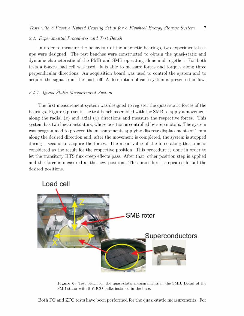
2.4.1. Quasi-Static Measurement System
The first measurement system was designed to register the quasi-static forces of the
bearings. Figure 6 presents the test bench assembled with the SMB to apply a movement
along the radial (x) and axial (z) directions and measure the respective forces. This
system has two linear actuators, whose position is controlled by step motors. The system
was programmed to proceed the measurements applying discrete displacements of 1 mm
along the desired direction and, after the movement is completed, the system is stopped
during 1 second to acquire the forces. The mean value of the force along this time is
considered as the result for the respective position. This procedure is done in order to
let the transitory HTS flux creep effects pass. After that, other position step is applied
and the force is measured at the new position. This procedure is repeated for all the
desired positions.
Figure 6. Test bench for the quasi-static measurements in the SMB. Detail of the
SMB stator with 8 YBCO bulks installed in the base.
Both FC and ZFC tests have been performed for the quasi-static measurements. For
Tests with a Passive Hybrid Bearing Setup for a Flywheel Energy Storage System 8
the ZFC tests, the rotor and stator were taken apart 130 mm before the superconductive
material was cooled down below its critical temperature. After cooling down, the
magnetic rotor was moved in a quasi-static movement, first approximating rotor and
stator up to a gap of 2 mm and then moving them away to the cooling position. In the
sequence, rotor and stator were approximated again to the minimal gap. For the FC
measurements, several cooling positions were tested: 27 mm, 22 mm, 17 mm and 12
mm. The HTS were cooled in one of the tested cooling position, and the magnetic rotor
was approximated until a minimal gap of 2 mm was reached. After that, the rotor was
moved up to z= 130 mm. Then, they were approximated again until reach a minimal
gap of 2 mm.
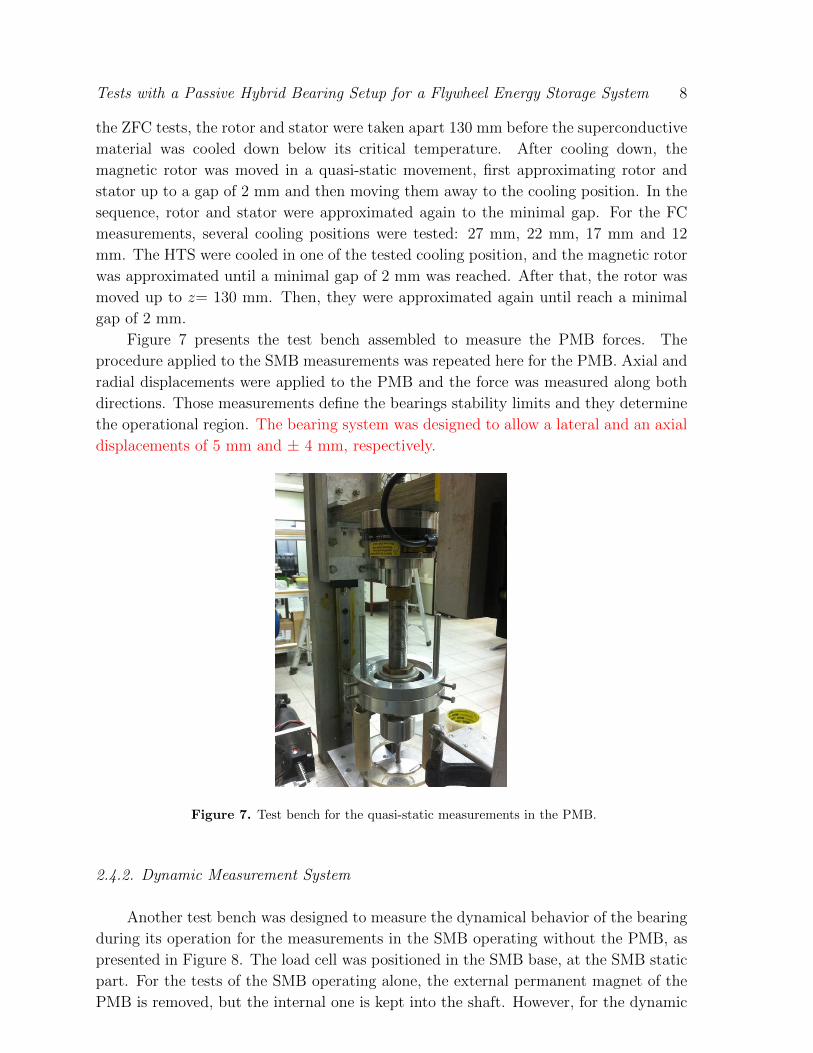
Figure 7 presents the test bench assembled to measure the PMB forces. The
procedure applied to the SMB measurements was repeated here for the PMB. Axial and
radial displacements were applied to the PMB and the force was measured along both
directions. Those measurements define the bearings stability limits and they determine
the operational region. The bearing system was designed to allow a lateral and an axial
displacements of 5 mm and ± 4 mm, respectively.
Figure 7. Test bench for the quasi-static measurements in the PMB.
2.4.2. Dynamic Measurement System
Another test bench was designed to measure the dynamical behavior of the bearing
during its operation for the measurements in the SMB operating without the PMB, as
presented in Figure 8. The load cell was positioned in the SMB base, at the SMB static
part. For the tests of the SMB operating alone, the external permanent magnet of the
PMB is removed, but the internal one is kept into the shaft. However, for the dynamic
Tests with a Passive Hybrid Bearing Setup for a Flywheel Energy Storage System 9
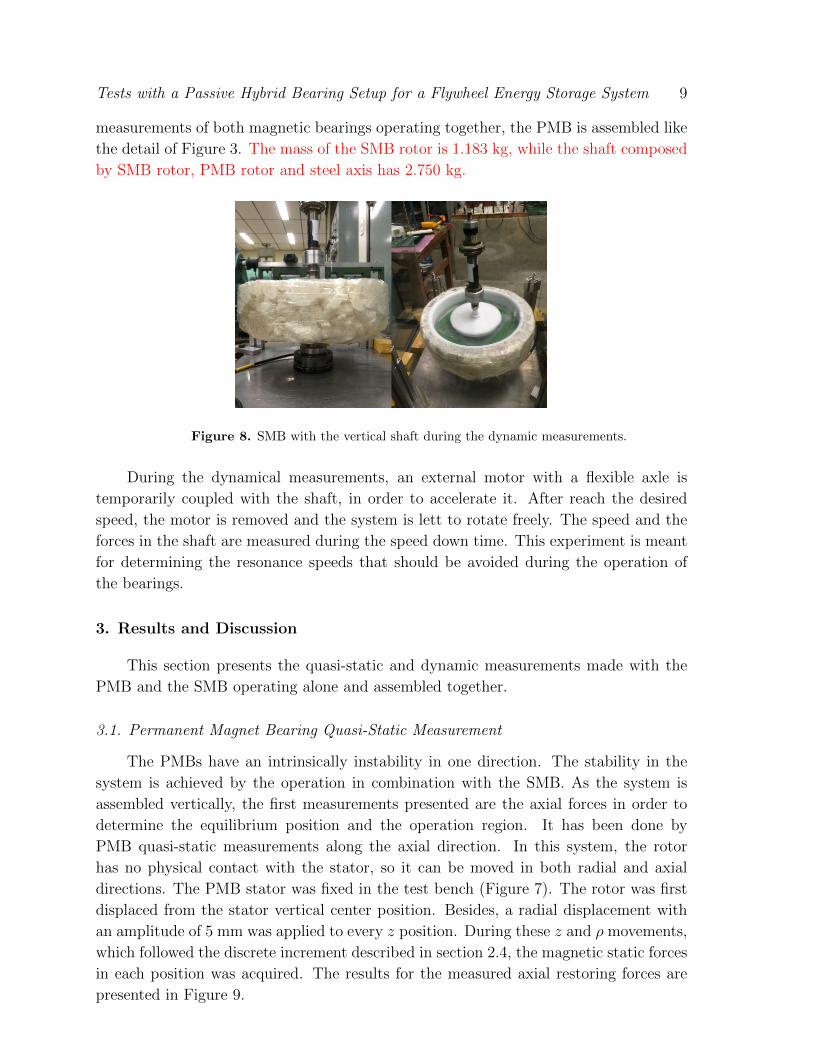
measurements of both magnetic bearings operating together, the PMB is assembled like
the detail of Figure 3. The mass of the SMB rotor is 1.183 kg, while the shaft composed
by SMB rotor, PMB rotor and steel axis has 2.750 kg.
Figure 8. SMB with the vertical shaft during the dynamic measurements.
During the dynamical measurements, an external motor with a flexible axle is
temporarily coupled with the shaft, in order to accelerate it. After reach the desired
speed, the motor is removed and the system is lett to rotate freely. The speed and the
forces in the shaft are measured during the speed down time. This experiment is meant
for determining the resonance speeds that should be avoided during the operation of
the bearings.
3. Results and Discussion
This section presents the quasi-static and dynamic measurements made with the
PMB and the SMB operating alone and assembled together.
3.1. Permanent Magnet Bearing Quasi-Static Measurement
The PMBs have an intrinsically instability in one direction. The stability in the
system is achieved by the operation in combination with the SMB. As the system is
assembled vertically, the first measurements presented are the axial forces in order to
determine the equilibrium position and the operation region. It has been done by
PMB quasi-static measurements along the axial direction. In this system, the rotor
has no physical contact with the stator, so it can be moved in both radial and axial
directions. The PMB stator was fixed in the test bench (Figure 7). The rotor was first
displaced from the stator vertical center position. Besides, a radial displacement with
an amplitude of 5 mm was applied to every z position. During these z and ρ movements,
which followed the discrete increment described in section 2.4, the magnetic static forces
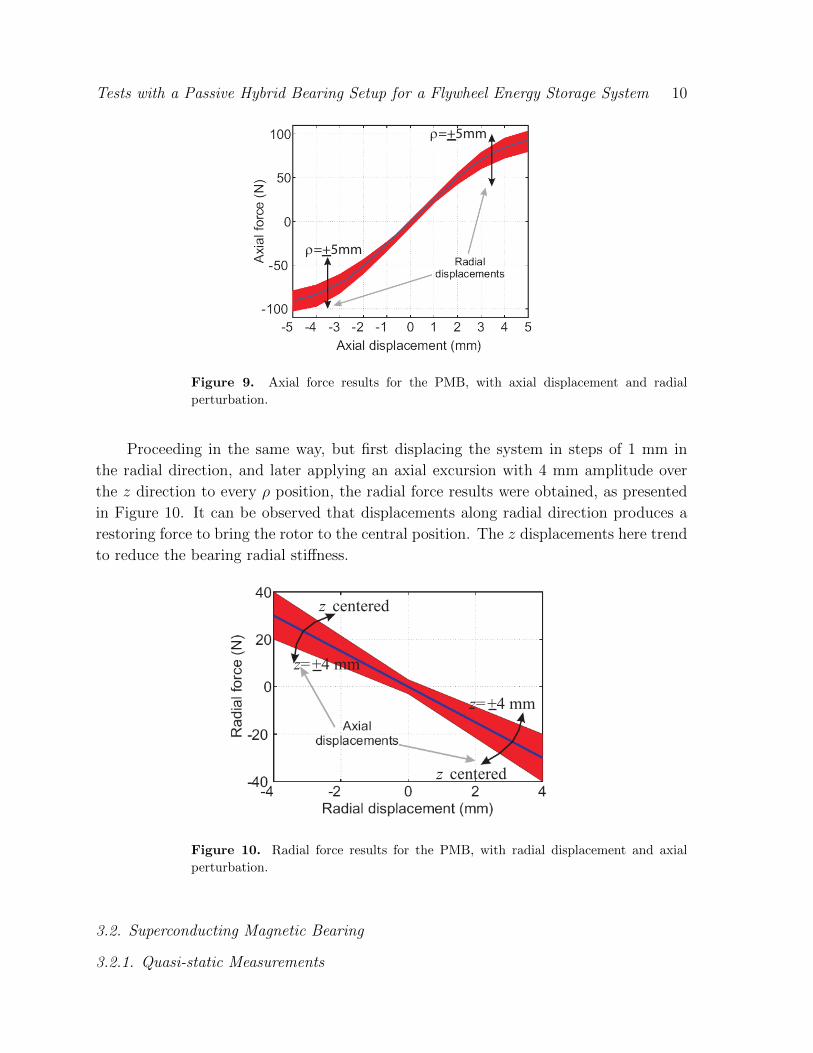
in each position was acquired. The results for the measured axial restoring forces are
presented in Figure 9.
Tests with a Passive Hybrid Bearing Setup for a Flywheel Energy Storage System 10
ρ=+5mm
ρ=+5mm
Figure 9. Axial force results for the PMB, with axial displacement and radial
perturbation.
Proceeding in the same way, but first displacing the system in steps of 1 mm in
the radial direction, and later applying an axial excursion with 4 mm amplitude over
the z direction to every ρ position, the radial force results were obtained, as presented
in Figure 10. It can be observed that displacements along radial direction produces a
restoring force to bring the rotor to the central position. The z displacements here trend
to reduce the bearing radial stiffness.
z centered
�
z=+4 mm
z=+4 mm
z centered
Figure 10. Radial force results for the PMB, with radial displacement and axial
perturbation.
3.2. Superconducting Magnetic Bearing
3.2.1. Quasi-static Measurements
Tests with a Passive Hybrid Bearing Setup for a Flywheel Energy Storage System 11
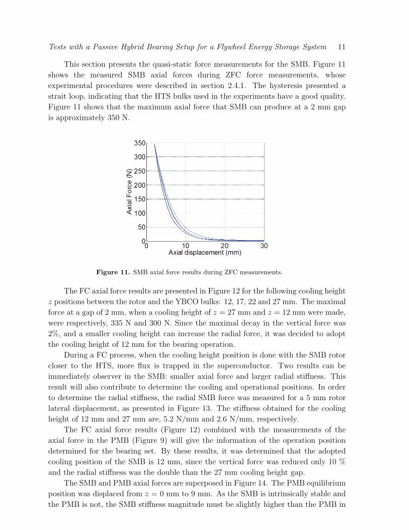
This section presents the quasi-static force measurements for the SMB. Figure 11
shows the measured SMB axial forces during ZFC force measurements, whose
experimental procedures were described in section 2.4.1. The hysteresis presented a
strait loop, indicating that the HTS bulks used in the experiments have a good quality.
Figure 11 shows that the maximum axial force that SMB can produce at a 2 mm gap
is approximately 350 N.
Figure 11. SMB axial force results during ZFC measurements.
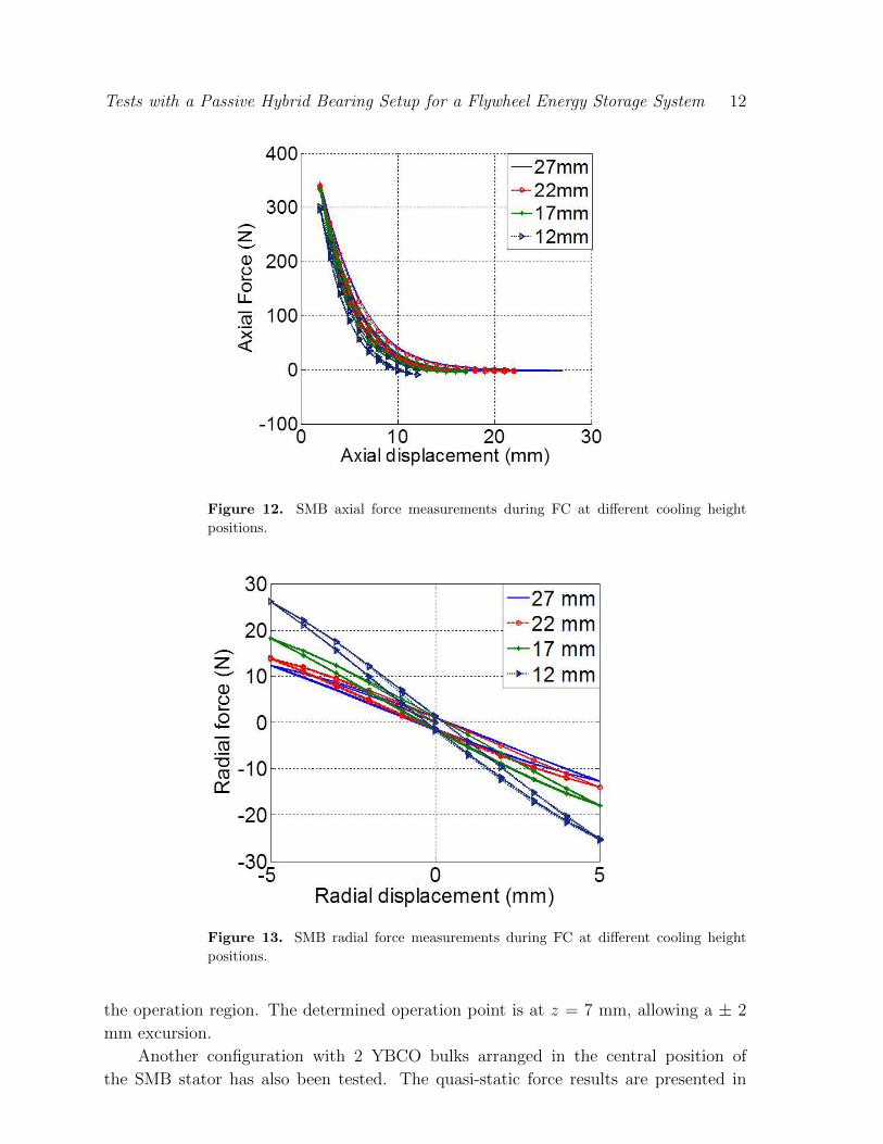
The FC axial force results are presented in Figure 12 for the following cooling height
z positions between the rotor and the YBCO bulks: 12, 17, 22 and 27 mm. The maximal
force at a gap of 2 mm, when a cooling height of z = 27 mm and z = 12 mm were made,
were respectively, 335 N and 300 N. Since the maximal decay in the vertical force was
2%, and a smaller cooling height can increase the radial force, it was decided to adopt
the cooling height of 12 mm for the bearing operation.
During a FC process, when the cooling height position is done with the SMB rotor
closer to the HTS, more flux is trapped in the superconductor. Two results can be
immediately observer in the SMB: smaller axial force and larger radial stiffness. This
result will also contribute to determine the cooling and operational positions. In order
to determine the radial stiffness, the radial SMB force was measured for a 5 mm rotor
lateral displacement, as presented in Figure 13. The stiffness obtained for the cooling
height of 12 mm and 27 mm are, 5.2 N/mm and 2.6 N/mm, respectively.
The FC axial force results (Figure 12) combined with the measurements of the
axial force in the PMB (Figure 9) will give the information of the operation position
determined for the bearing set. By these results, it was determined that the adopted
cooling position of the SMB is 12 mm, since the vertical force was reduced only 10 %
and the radial stiffness was the double than the 27 mm cooling height gap.
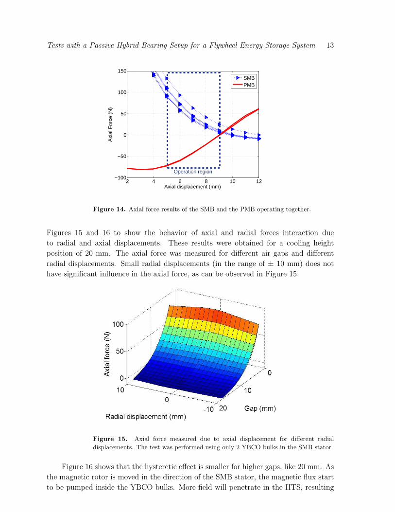
The SMB and PMB axial forces are superposed in Figure 14. The PMB equilibrium
position was displaced from z = 0 mm to 9 mm. As the SMB is intrinsically stable and
the PMB is not, the SMB stiffness magnitude must be slightly higher than the PMB in
Tests with a Passive Hybrid Bearing Setup for a Flywheel Energy Storage System 12
Figure 12. SMB axial force measurements during FC at different cooling height
positions.
Figure 13. SMB radial force measurements during FC at different cooling height
positions.
the operation region. The determined operation point is at z = 7 mm, allowing a ± 2
mm excursion.
Another configuration with 2 YBCO bulks arranged in the central position of
the SMB stator has also been tested. The quasi-static force results are presented in
Tests with a Passive Hybrid Bearing Setup for a Flywheel Energy Storage System 13
2 4 6 8 10 12−100
−50
0
50
100
150
Axi
al F
orce
(N
)
Axial displacement (mm)
SMBPMB
Operation region
Figure 14. Axial force results of the SMB and the PMB operating together.
Figures 15 and 16 to show the behavior of axial and radial forces interaction due
to radial and axial displacements. These results were obtained for a cooling height
position of 20 mm. The axial force was measured for different air gaps and different
radial displacements. Small radial displacements (in the range of ± 10 mm) does not
have significant influence in the axial force, as can be observed in Figure 15.
Figure 15. Axial force measured due to axial displacement for different radial
displacements. The test was performed using only 2 YBCO bulks in the SMB stator.
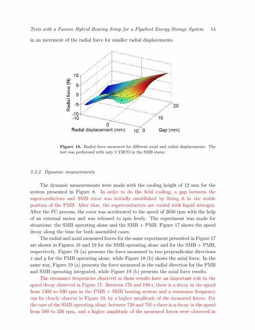
Figure 16 shows that the hysteretic effect is smaller for higher gaps, like 20 mm. As
the magnetic rotor is moved in the direction of the SMB stator, the magnetic flux start
to be pumped inside the YBCO bulks. More field will penetrate in the HTS, resulting
Tests with a Passive Hybrid Bearing Setup for a Flywheel Energy Storage System 14
in an increment of the radial force for smaller radial displacements.
Figure 16. Radial force measured for different axial and radial displacements. The
test was performed with only 2 YBCO in the SMB stator.
3.2.2. Dynamic measurements
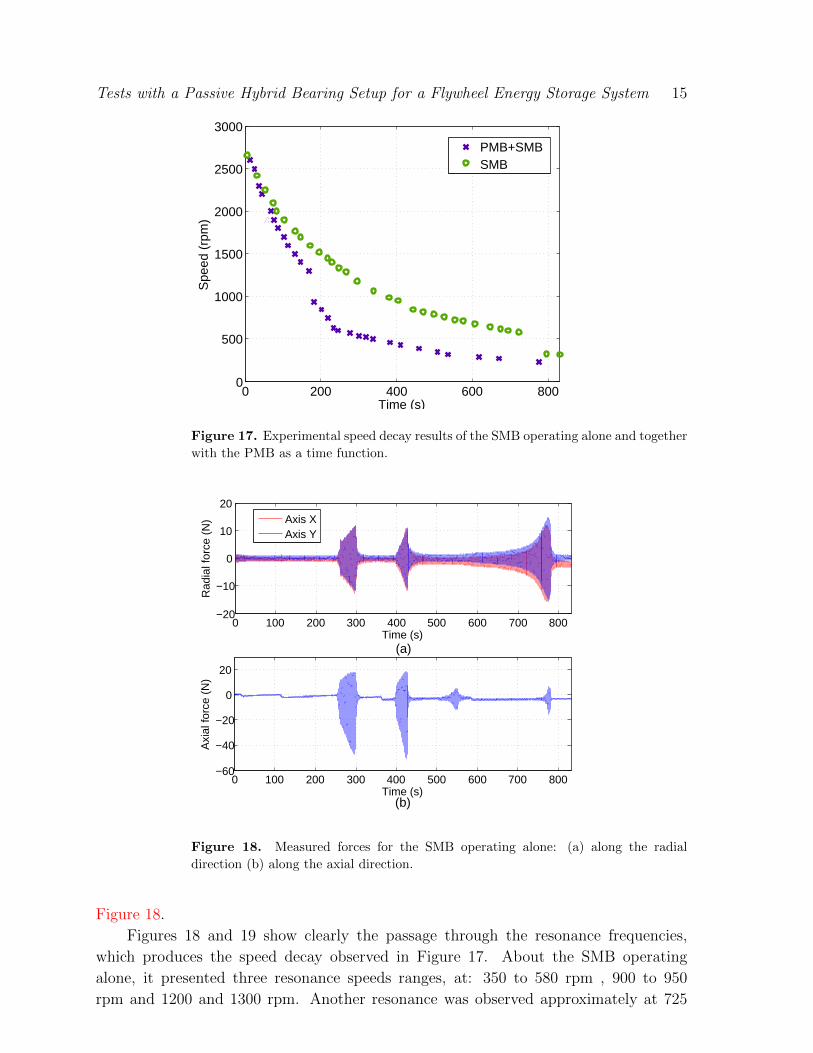
The dynamic measurements were made with the cooling height of 12 mm for the
system presented in Figure 8. In order to do the field cooling, a gap between the
superconductors and SMB rotor was initially established by fixing it in the stable
position of the PMB. After that, the superconductors are cooled with liquid nitrogen.
After the FC process, the rotor was accelerated to the speed of 2650 rpm with the help
of an external motor and was released to spin freely. The experiment was made for
situations: the SMB operating alone and the SMB + PMB. Figure 17 shows the speed
decay along the time for both assembled cases.
The radial and axial measured forces for the same experiment presented in Figure 17
are shown in Figures 18 and 19 for the SMB operating alone and for the SMB + PMB,
respectively. Figure 18 (a) presents the force measured in two perpendicular directions
x and y for the PMB operating alone, while Figure 18 (b) shows the axial force. In the
same way, Figure 19 (a) presents the force measured in the radial direction for the PMB
and SMB operating integrated, while Figure 19 (b) presents the axial force results.
The resonance frequencies observed in these results have an important role in the
speed decay observed in Figure 17. Between 170 and 180 s, there is a decay in the speed
from 1300 to 930 rpm in the PMB + SMB bearing system and a resonance frequency
can be clearly observe in Figure 19, by a higher amplitude of the measured forces. For
the case of the SMB operating alone, between 720 and 795 s there is a decay in the speed
from 580 to 330 rpm, and a higher amplitude of the measured forces were observed in
Tests with a Passive Hybrid Bearing Setup for a Flywheel Energy Storage System 15
0 200 400 600 8000
500
1000
1500
2000
2500
3000
Time (s)
Spe
ed (
rpm
)
PMB+SMBSMB
Figure 17. Experimental speed decay results of the SMB operating alone and together
with the PMB as a time function.
0 100 200 300 400 500 600 700 800−20
−10
0
10
20
Rad
ial f
orce
(N
)
Time (s)(a)
Axis XAxis Y
0 100 200 300 400 500 600 700 800−60
−40
−20
0
20
Axi
al fo
rce
(N)
Time (s)(b)
Figure 18. Measured forces for the SMB operating alone: (a) along the radial
direction (b) along the axial direction.
Figure 18.
Figures 18 and 19 show clearly the passage through the resonance frequencies,
which produces the speed decay observed in Figure 17. About the SMB operating
alone, it presented three resonance speeds ranges, at: 350 to 580 rpm , 900 to 950
rpm and 1200 and 1300 rpm. Another resonance was observed approximately at 725
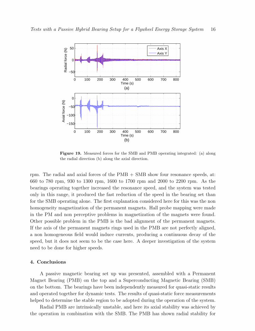
Tests with a Passive Hybrid Bearing Setup for a Flywheel Energy Storage System 16
0 100 200 300 400 500 600 700 800
−150
−100
−50
0
Axi
al fo
rce
(N)
Time (s)(b)
0 100 200 300 400 500 600 700 800
−50
0
50
Time (s)
Rad
ial f
orce
(N
)
(a)
Axis XAxis Y
Figure 19. Measured forces for the SMB and PMB operating integrated: (a) along
the radial direction (b) along the axial direction.
rpm. The radial and axial forces of the PMB + SMB show four resonance speeds, at:
660 to 780 rpm, 930 to 1300 rpm, 1600 to 1700 rpm and 2000 to 2200 rpm. As the
bearings operating together increased the resonance speed, and the system was tested
only in this range, it produced the fast reduction of the speed in the bearing set than
for the SMB operating alone. The first explanation considered here for this was the non
homogeneity magnetization of the permanent magnets. Hall probe mapping were made
in the PM and non perceptive problems in magnetization of the magnets were found.
Other possible problem in the PMB is the bad alignment of the permanent magnets.
If the axis of the permanent magnets rings used in the PMB are not perfectly aligned,
a non homogeneous field would induce currents, producing a continuous decay of the
speed, but it does not seem to be the case here. A deeper investigation of the system
need to be done for higher speeds.
4. Conclusions
A passive magnetic bearing set up was presented, assembled with a Permanent
Magnet Bearing (PMB) on the top and a Superconducting Magnetic Bearing (SMB)
on the bottom. The bearings have been independently measured for quasi-static results
and operated together for dynamic tests. The results of quasi-static force measurements
helped to determine the stable region to be adopted during the operation of the system.
Radial PMB are intrinsically unstable, and here its axial stability was achieved by
the operation in combination with the SMB. The PMB has shown radial stability for
Tests with a Passive Hybrid Bearing Setup for a Flywheel Energy Storage System 17
small radial and axial displacements. The PMB presented an axial stiffness of 20 N/mm
with almost a linear behavior for small axial displacement. The axial force of the SMB
increases with almost an exponential rate with the axial position.
For the complete implementation of passive magnetic bearings system, the SMB
seems to be a good option, since it presents a similar radial force behavior to that of the
bearing set. Moreover, the axial force is reduced but stiffness is bigger that presented
by the bearing set.
Dynamic results presented a faster decay of the speed for the PMB+SMB than the
one observed for the SMB operating alone. This result was attributed to an increment
in the resonance speed of the bearing set. A future investigation need to be done after
the introduction of the flywheel and the motor/generator in order to study the new
dynamics with the complete system.
Acknowledgments
The authors would like to thank the financial support received from CNPq,
FAPERJ, Swedish Research Council, The Swedish Centre for Smart Grids and Energy
Storage (SweGRIDS), STandUP for Energy and CONACYT.
References
[1] J. Cho, S. Jeong, and Y. Kim. Commercial and research battery technologies for electrical energy
storage applications. Progress in Energy and Combustion Science, 48:84–101, 2015.
[2] Nicola Armaroli and Vincenzo Balzani. The hydrogen issue. ChemSusChem, 4(1):21–36, 2011.
[3] Manisha Vangari, Tonya Pryor, and Li Jiang. Supercapacitors: review of materials and fabrication
methods. Journal of Energy Engineering, 139(2):72–79, 2012.
[4] M. H. Ali, B. Wu, and R. A. Dougal. An overview of smes applications in power and energy
systems. IEEE Transactions on Sustainable Energy, 1(1):38–47, April 2010.
[5] F N Werfel, U Floegel-Delor, R Rothfeld, T Riedel, B Goebel, D Wippich, and P Schirrmeister.
Superconductor bearings, flywheels and transportation. Superconductor Science and Technology,
25(1):014007, 2012.
[6] Atul Sharma, V.V. Tyagi, C.R. Chen, and D. Buddhi. Review on thermal energy storage with
phase change materials and applications. Renewable and Sustainable Energy Reviews, 13(2):318
– 345, 2009.
[7] R. Saidur, N.A. Rahim, and M. Hasanuzzaman. A review on compressed-air energy use and energy
savings. Renewable and Sustainable Energy Reviews, 14(4):1135 – 1153, 2010.
[8] J.P. Deane, B.P. Gallachir, and E.J. McKeogh. Techno-economic review of existing and new
pumped hydro energy storage plant. Renewable and Sustainable Energy Reviews, 14(4):1293 –
1302, 2010.
[9] T.M.I. Mahlia, T.J. Saktisahdan, A. Jannifar, M.H. Hasan, and H.S.C. Matseelar. A review
of available methods and development on energy storage; technology update. Renewable and
Sustainable Energy Reviews, 33:532–545, 2014.
[10] Sam Koohi-Kamali, V.V. Tyagi, N.A. Rahim, N.L. Panwar, and H. Mokhlis. Emergence of energy
storage technologies as the solution for reliable operation of smart power systems: A review.
Renewable and Sustainable Energy Reviews, 25:135 – 165, 2013.
[11] S. Vazquez, S. M. Lukic, E. Galvan, L. G. Franquelo, and J. M. Carrasco. Energy storage systems
Tests with a Passive Hybrid Bearing Setup for a Flywheel Energy Storage System 18
for transport and grid applications. IEEE Transactions on Industrial Electronics, 57(12):3881–
3895, Dec 2010.
[12] J. Cibulka. Kinetic energy recovery system by means of flywheel energy storage. Advanced
Engineering, 3(1):27–38, 2009.
[13] A. A. Boretti. Improvements of vehicle fuel economy using mechanical regenerative braking.
International Journal of Vehicle Design, 55(1):35–48, 2011.
[14] Rubens De Andrade, Guilherme G Sotelo, Antonio C Ferreira, Luis GB Rolim, Jose L da Silva Neto,
Richard M Stephan, Walter I Suemitsu, and Roberto Nicolsky. Flywheel energy storage system
description and tests. Applied Superconductivity, IEEE Transactions on, 17(2):2154–2157, 2007.
[15] Juan Manuel Carrasco, Leopoldo Garcia Franquelo, Jan T Bialasiewicz, Eduardo Galvan, Ramon
C Portillo Guisado, Ma Angeles Martın Prats, Jose Ignacio Leon, and Narciso Moreno-Alfonso.
Power-electronic systems for the grid integration of renewable energy sources: A survey.
Industrial Electronics, IEEE Transactions on, 53(4):1002–1016, 2006.
[16] Y. Feng, H. Lin, J. Yan, and Y. Huang. Loss component analysis of flywheel energy storage system
with mechanical bearings. Dongnan Daxue Xuebao (Ziran Kexue Ban)/Journal of Southeast
University (Natural Science Edition), 43(1):71–75, 2013. cited By 0.
[17] S. Jiang, H. Wang, and S. Wen. Flywheel energy storage system with a permanent magnet bearing
and a pair of hybrid ceramic ball bearings. Journal of Mechanical Science and Technology,
28(12):5043–5053, 2014.
[18] M. A. Pichot, J. P. Kajs, B. R. Murphy, A. Ouroua, B. M. Rech, R. J. Hayes, J. H. Beno, G. D.
Buckner, and A. B. Palazzolo. Active magnetic bearings for energy storage systems for combat
vehicles. IEEE Transactions on Magnetics, 37(1):318–323, Jan 2001.
[19] Y.H. Han, B.J. Park, S.Y. Jung, and S.C. Han. Study of superconductor bearings for a 35 kwh
superconductor flywheel energy storage system. Physica C: Superconductivity, 483:156 – 161,
2012.
[20] K. Murakami, M. Komori, H. Mitsuda, and A. Inoue. Design of an energy storage flywheel
system using permanent magnet bearing (pmb) and superconducting magnetic bearing (smb).
Cryogenics, 47(4):272 – 277, 2007.
[21] H. Mitsuda, A. Inoue, B. Nakaya, and M. Komori. Improvement of energy storage flywheel system
with smb and pmb and its performances. IEEE Transactions on Applied Superconductivity,
19(3):2091–2094, June 2009.
[22] M. Subkhan and M. Komori. New concept for flywheel energy storage system using smb and pmb.
IEEE Transactions on Applied Superconductivity, 21(3):1485–1488, June 2011.
[23] G.G. Sotelo, D.H.N. Dias, R. De Andrade Jr., and R.M. Stephan. Tests on a superconductor
linear magnetic bearing of a full-scale maglev vehicle. IEEE Transactions on Applied
Superconductivity, 21(3 PART 2):1464–1468, 2011. cited By 25.
[24] G. G. Sotelo, A. C. Ferreira, and R. de Andrade. Halbach array superconducting magnetic
bearing for a flywheel energy storage system. IEEE Transactions on Applied Superconductivity,
15(2):2253–2256, June 2005.
[25] G. G. Sotelo, R. de Andrade, and A. C. Ferreira. Magnetic bearing sets for a flywheel system.
IEEE Transactions on Applied Superconductivity, 17(2):2150–2153, June 2007.
[26] Elkin Rodriguez, Juan de Santiago, Jesus Jose Perez-Loya, Felipe S Costa, Guilherme G Sotelo,
Janaina Goncalves de Oliveira, and Richard M Stephan. Analysis of passive magnetic bearings
for kinetic energy storage systems. In 14th International Symposium on Magnetic Bearings,
2014.
[27] Elkin Rodriguez, Jesus Jose Perez-Loya, Juan de Santiago, Felipe S Costa, Guilherme G Sotelo,
Janaına G Oliveira, and Richard M Stephan. Passive magnetic bearing system. In 22nd
International Conference on Magnetically Levitaded Systems and Linear Drives, 2014.