___________________
___________________
___________________
___________________
___________________
___________________
___________________
___________________
___________________
SIMATIC
S7-1500/ET 200MP Digital output module DQ 16x24VDC/0.5A HF (6ES7522-1BH01-0AB0) Manual
09/2016 A5E35683409-AB
Preface
Documentation guide 1
Product overview 2
Wiring 3
Parameters/address space 4
Interrupts/diagnostics alarms 5
Technical specifications 6
Dimensional drawing A
Parameter data records B
Siemens AG Division Digital Factory Postfach 48 48 90026 NÜRNBERG GERMANY
A5E35683409-AB Ⓟ 11/2016 Subject to change
Copyright © Siemens AG 2015 - 2016. All rights reserved
Legal information Warning notice system
This manual contains notices you have to observe in order to ensure your personal safety, as well as to prevent damage to property. The notices referring to your personal safety are highlighted in the manual by a safety alert symbol, notices referring only to property damage have no safety alert symbol. These notices shown below are graded according to the degree of danger.
DANGER indicates that death or severe personal injury will result if proper precautions are not taken.
WARNING indicates that death or severe personal injury may result if proper precautions are not taken.
CAUTION indicates that minor personal injury can result if proper precautions are not taken.
NOTICE indicates that property damage can result if proper precautions are not taken.
If more than one degree of danger is present, the warning notice representing the highest degree of danger will be used. A notice warning of injury to persons with a safety alert symbol may also include a warning relating to property damage.
Qualified Personnel The product/system described in this documentation may be operated only by personnel qualified for the specific task in accordance with the relevant documentation, in particular its warning notices and safety instructions. Qualified personnel are those who, based on their training and experience, are capable of identifying risks and avoiding potential hazards when working with these products/systems.
Proper use of Siemens products Note the following:
WARNING Siemens products may only be used for the applications described in the catalog and in the relevant technical documentation. If products and components from other manufacturers are used, these must be recommended or approved by Siemens. Proper transport, storage, installation, assembly, commissioning, operation and maintenance are required to ensure that the products operate safely and without any problems. The permissible ambient conditions must be complied with. The information in the relevant documentation must be observed.
Trademarks All names identified by ® are registered trademarks of Siemens AG. The remaining trademarks in this publication may be trademarks whose use by third parties for their own purposes could violate the rights of the owner.
Disclaimer of Liability We have reviewed the contents of this publication to ensure consistency with the hardware and software described. Since variance cannot be precluded entirely, we cannot guarantee full consistency. However, the information in this publication is reviewed regularly and any necessary corrections are included in subsequent editions.
Siemens Controls
Digital output module DQ 16x24VDC/0.5A HF (6ES7522-1BH01-0AB0) 4 Manual, 09/2016, A5E35683409-AB
Preface
Purpose of the documentation This manual supplements the system manual S7-1500/ET 200MP (https://support.industry.siemens.com/cs/ww/en/view/59191792).
Functions that relate in general to the systems are described in this system manual.
The information provided in this manual and in the system/function manuals supports you in commissioning the systems.
Changes compared to previous version Compared to the previous version, this manual contains the following change:
Original texts of the license conditions and copyright notes for open-source software are available on the Internet as of 09/2016.
Conventions The term "CPU" is used in this manual both for the CPUs of the S7-1500 automation system and for interface modules of the ET 200MP distributed I/O system.
Please also observe notes marked as follows:
Note
A note contains important information on the product described in the documentation, on the handling of the product or on the section of the documentation to which particular attention should be paid.
Preface
Digital output module DQ 16x24VDC/0.5A HF (6ES7522-1BH01-0AB0) Manual, 09/2016, A5E35683409-AB 5
Security information Siemens provides products and solutions with industrial security functions that support the secure operation of plants, systems, machines and networks.
In order to protect plants, systems, machines and networks against cyber threats, it is necessary to implement – and continuously maintain – a holistic, state-of-the-art industrial security concept. Siemens’ products and solutions only form one element of such a concept.
Customer is responsible to prevent unauthorized access to its plants, systems, machines and networks. Systems, machines and components should only be connected to the enterprise network or the internet if and to the extent necessary and with appropriate security measures (e.g. use of firewalls and network segmentation) in place.
Additionally, Siemens’ guidance on appropriate security measures should be taken into account. For more information about industrial security, please visit (http://www.siemens.com/industrialsecurity).
Siemens’ products and solutions undergo continuous development to make them more secure. Siemens strongly recommends to apply product updates as soon as available and to always use the latest product versions. Use of product versions that are no longer supported, and failure to apply latest updates may increase customer’s exposure to cyber threats.
To stay informed about product updates, subscribe to the Siemens Industrial Security RSS Feed under (http://www.siemens.com/industrialsecurity).
Open Source Software Open-source software is used in the firmware of the I/O modules. Open Source Software is provided free of charge. We are liable for the product described, including the open-source software contained in it, pursuant to the conditions applicable to the product. Siemens accepts no liability for the use of the open source software over and above the intended program sequence, or for any faults caused by modifications to the software.
For legal reasons, we are obliged to publish the original text of the license conditions and copyright notices. Please read the information relating to this on the Internet (https://support.industry.siemens.com/cs/ww/en/view/109741045).
Siemens Controls
Digital output module DQ 16x24VDC/0.5A HF (6ES7522-1BH01-0AB0) 6 Manual, 09/2016, A5E35683409-AB
Table of contents
Preface ................................................................................................................................................... 4
1 Documentation guide .............................................................................................................................. 7
2 Product overview .................................................................................................................................. 11
2.1 Properties ............................................................................................................................... 11
3 Wiring ................................................................................................................................................... 13
4 Parameters/address space ................................................................................................................... 15
4.1 Parameters ............................................................................................................................. 15
4.2 Description of parameters ...................................................................................................... 16
4.3 Address space ....................................................................................................................... 17
5 Interrupts/diagnostics alarms................................................................................................................. 22
5.1 Status and error displays ....................................................................................................... 22
5.2 Interrupts ................................................................................................................................ 24
5.3 Diagnostics alarms ................................................................................................................. 24
6 Technical specifications ........................................................................................................................ 25
A Dimensional drawing ............................................................................................................................. 29
A.1 Dimensional drawing .............................................................................................................. 29
B Parameter data records ........................................................................................................................ 31
B.1 Parameter assignment and structure of the parameter data records .................................... 31
Digital output module DQ 16x24VDC/0.5A HF (6ES7522-1BH01-0AB0) Manual, 09/2016, A5E35683409-AB 7
Documentation guide 1
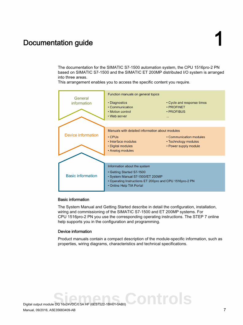
The documentation for the SIMATIC S7-1500 automation system, the CPU 1516pro-2 PN based on SIMATIC S7-1500 and the SIMATIC ET 200MP distributed I/O system is arranged into three areas. This arrangement enables you to access the specific content you require.
Basic information
The System Manual and Getting Started describe in detail the configuration, installation, wiring and commissioning of the SIMATIC S7-1500 and ET 200MP systems. For CPU 1516pro-2 PN you use the corresponding operating instructions. The STEP 7 online help supports you in the configuration and programming.
Device information
Product manuals contain a compact description of the module-specific information, such as properties, wiring diagrams, characteristics and technical specifications.
Siemens Controls
Documentation guide
Digital output module DQ 16x24VDC/0.5A HF (6ES7522-1BH01-0AB0) 8 Manual, 09/2016, A5E35683409-AB
General information
The function manuals contain detailed descriptions on general topics regarding the SIMATIC S7-1500 and ET 200MP systems, e.g. diagnostics, communication, motion control, Web server, OPC UA.
You can download the documentation free of charge from the Internet (http://w3.siemens.com/mcms/industrial-automation-systems-simatic/en/manual-overview/Pages/Default.aspx).
Changes and supplements to the manuals are documented in a Product Information.
You can download the product information free of charge from the Internet (https://support.industry.siemens.com/cs/us/en/view/68052815).
Manual Collection S7-1500/ET 200MP The Manual Collection contains the complete documentation on the SIMATIC S7-1500 automation system and the ET 200MP distributed I/O system gathered together in one file.
You can find the Manual Collection on the Internet (https://support.industry.siemens.com/cs/ww/en/view/86140384).
SIMATIC S7-1500 comparison list for programming languages The comparison list contains an overview of which instructions and functions you can use for which controller families.
You can find the comparison list on the Internet (https://support.industry.siemens.com/cs/ww/en/view/86630375).
"mySupport" With "mySupport", your personal workspace, you make the best out of your Industry Online Support.
In "mySupport", you can save filters, favorites and tags, request CAx data and compile your personal library in the Documentation area. In addition, your data is already filled out in support requests and you can get an overview of your current requests at any time.
You must register once to use the full functionality of "mySupport".
You can find "mySupport" on the Internet (https://support.industry.siemens.com/My/ww/en).
"mySupport" - Documentation In the Documentation area in "mySupport" you can combine entire manuals or only parts of these to your own manual. You can export the manual as PDF file or in a format that can be edited later.
You can find "mySupport" - Documentation on the Internet (http://support.industry.siemens.com/My/ww/en/documentation).
Documentation guide
Digital output module DQ 16x24VDC/0.5A HF (6ES7522-1BH01-0AB0) Manual, 09/2016, A5E35683409-AB 9
"mySupport" - CAx data In the CAx data area in "mySupport", you can access the current product data for your CAx or CAe system.
You configure your own download package with a few clicks.
In doing so you can select:
● Product images, 2D dimension drawings, 3D models, internal circuit diagrams, EPLAN macro files
● Manuals, characteristics, operating manuals, certificates
● Product master data
You can find "mySupport" - CAx data on the Internet (http://support.industry.siemens.com/my/ww/en/CAxOnline).
Application examples The application examples support you with various tools and examples for solving your automation tasks. Solutions are shown in interplay with multiple components in the system - separated from the focus on individual products.
You will find the application examples on the Internet (https://support.industry.siemens.com/sc/ww/en/sc/2054).
TIA Selection Tool With the TIA Selection Tool, you can select, configure and order devices for Totally Integrated Automation (TIA). This tool is the successor of the SIMATIC Selection Tool and combines the known configurators for automation technology into one tool. With the TIA Selection Tool, you can generate a complete order list from your product selection or product configuration.
You can find the TIA Selection Tool on the Internet (http://w3.siemens.com/mcms/topics/en/simatic/tia-selection-tool).
Siemens Controls
Documentation guide
Digital output module DQ 16x24VDC/0.5A HF (6ES7522-1BH01-0AB0) 10 Manual, 09/2016, A5E35683409-AB
SIMATIC Automation Tool You can use the SIMATIC Automation Tool to run commissioning and maintenance activities simultaneously on various SIMATIC S7 stations as a bulk operation independently of the TIA Portal.
The SIMATIC Automation Tool provides a multitude of functions:
● Scanning of a PROFINET/Ethernet network and identification of all connected CPUs
● Address assignment (IP, subnet, gateway) and station name (PROFINET device) to a CPU
● Transfer of the date and the programming device/PC time converted to UTC time to the module
● Program download to CPU
● Operating mode switchover RUN/STOP
● Localization of the CPU by means of LED flashing
● Reading out CPU error information
● Reading the CPU diagnostic buffer
● Reset to factory settings
● Updating the firmware of the CPU and connected modules
You can find the SIMATIC Automation Tool on the Internet (https://support.industry.siemens.com/cs/ww/en/view/98161300).
PRONETA With SIEMENS PRONETA (PROFINET network analysis), you analyze the PROFINET network during commissioning. PRONETA features two core functions:
● The topology overview independently scans PROFINET and all connected components.
● The IO check is a fast test of the wiring and the module configuration of a system.
You can find SIEMENS PRONETA on the Internet (https://support.industry.siemens.com/cs/ww/en/view/67460624).
Digital output module DQ 16x24VDC/0.5A HF (6ES7522-1BH01-0AB0) Manual, 09/2016, A5E35683409-AB 11
Product overview 2 2.1 Properties
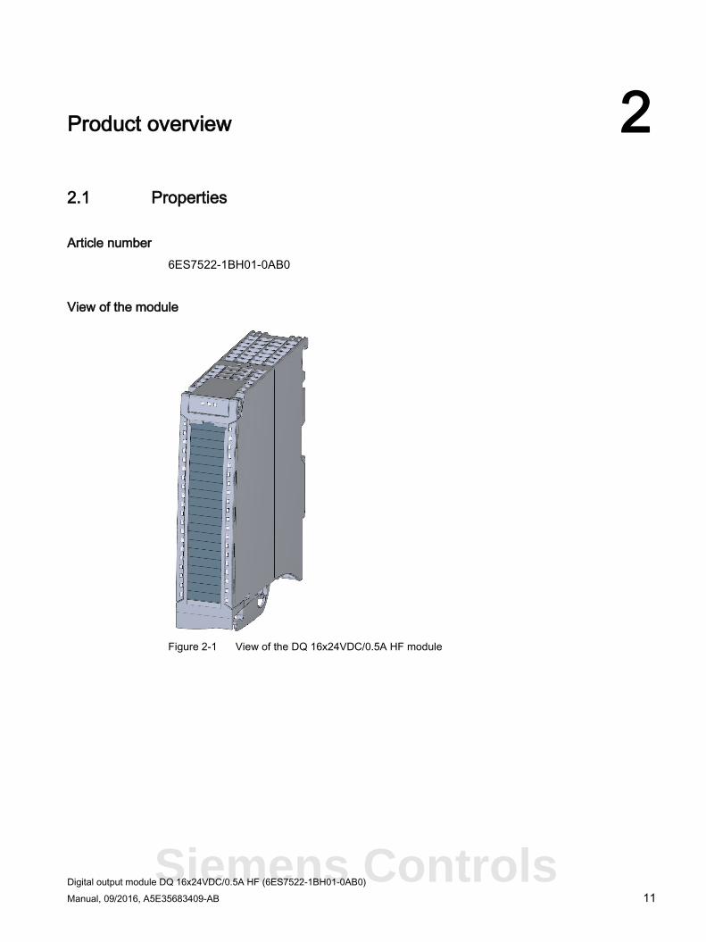
Article number 6ES7522-1BH01-0AB0
View of the module
Figure 2-1 View of the DQ 16x24VDC/0.5A HF module
Siemens Controls
Product overview 2.1 Properties
Digital output module DQ 16x24VDC/0.5A HF (6ES7522-1BH01-0AB0) 12 Manual, 09/2016, A5E35683409-AB
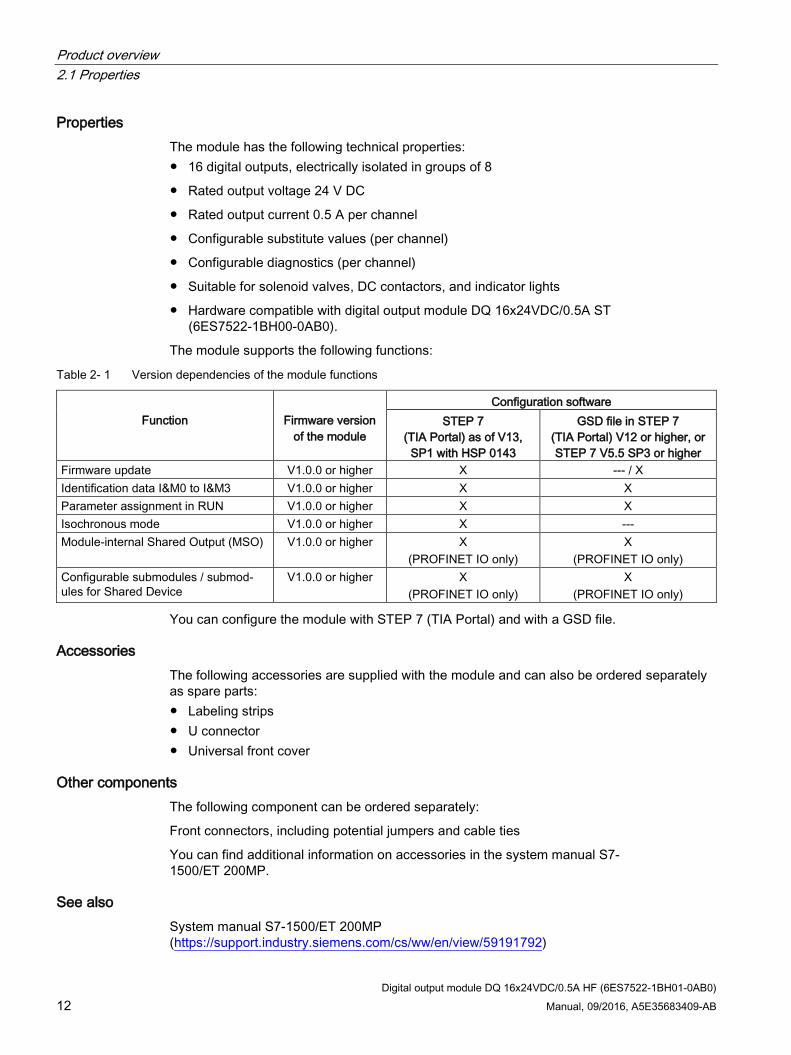
Properties The module has the following technical properties: ● 16 digital outputs, electrically isolated in groups of 8
● Rated output voltage 24 V DC
● Rated output current 0.5 A per channel
● Configurable substitute values (per channel)
● Configurable diagnostics (per channel)
● Suitable for solenoid valves, DC contactors, and indicator lights
● Hardware compatible with digital output module DQ 16x24VDC/0.5A ST (6ES7522-1BH00-0AB0).
The module supports the following functions:
Table 2- 1 Version dependencies of the module functions
Function
Firmware version
of the module
Configuration software STEP 7
(TIA Portal) as of V13, SP1 with HSP 0143
GSD file in STEP 7 (TIA Portal) V12 or higher, or STEP 7 V5.5 SP3 or higher
Firmware update V1.0.0 or higher X --- / X Identification data I&M0 to I&M3 V1.0.0 or higher X X Parameter assignment in RUN V1.0.0 or higher X X Isochronous mode V1.0.0 or higher X --- Module-internal Shared Output (MSO) V1.0.0 or higher X
(PROFINET IO only) X
(PROFINET IO only) Configurable submodules / submod-ules for Shared Device
V1.0.0 or higher X (PROFINET IO only)
X (PROFINET IO only)
You can configure the module with STEP 7 (TIA Portal) and with a GSD file.
Accessories The following accessories are supplied with the module and can also be ordered separately as spare parts: ● Labeling strips ● U connector ● Universal front cover
Other components The following component can be ordered separately:
Front connectors, including potential jumpers and cable ties
You can find additional information on accessories in the system manual S7-1500/ET 200MP.
See also System manual S7-1500/ET 200MP (https://support.industry.siemens.com/cs/ww/en/view/59191792)
Digital output module DQ 16x24VDC/0.5A HF (6ES7522-1BH01-0AB0) 13 Manual, 09/2016, A5E35683409-AB
Wiring 3
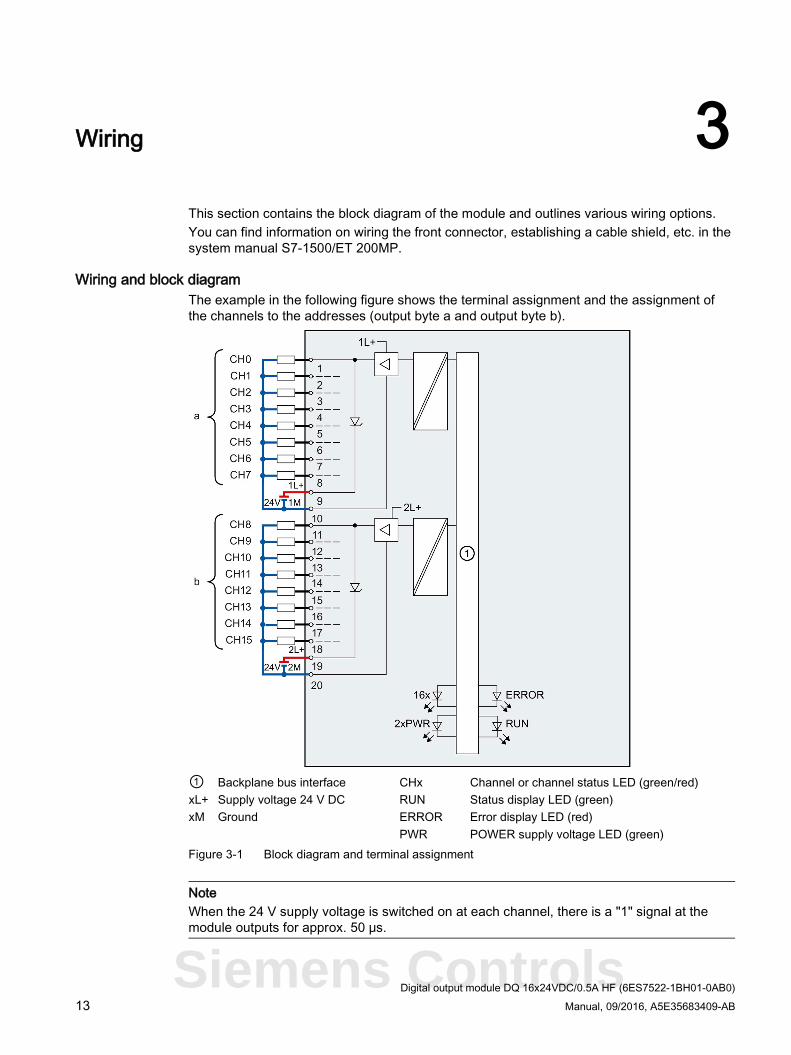
This section contains the block diagram of the module and outlines various wiring options. You can find information on wiring the front connector, establishing a cable shield, etc. in the system manual S7-1500/ET 200MP.
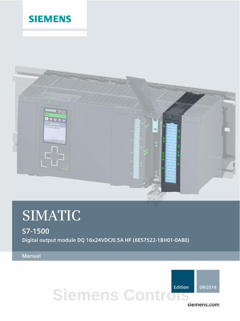
Wiring and block diagram The example in the following figure shows the terminal assignment and the assignment of the channels to the addresses (output byte a and output byte b).
① Backplane bus interface CHx Channel or channel status LED (green/red) xL+ Supply voltage 24 V DC RUN Status display LED (green) xM Ground ERROR Error display LED (red) PWR POWER supply voltage LED (green) Figure 3-1 Block diagram and terminal assignment
Note When the 24 V supply voltage is switched on at each channel, there is a "1" signal at the module outputs for approx. 50 μs.
Siemens Controls
Wiring
Digital output module DQ 16x24VDC/0.5A HF (6ES7522-1BH01-0AB0) 14 Manual, 09/2016, A5E35683409-AB
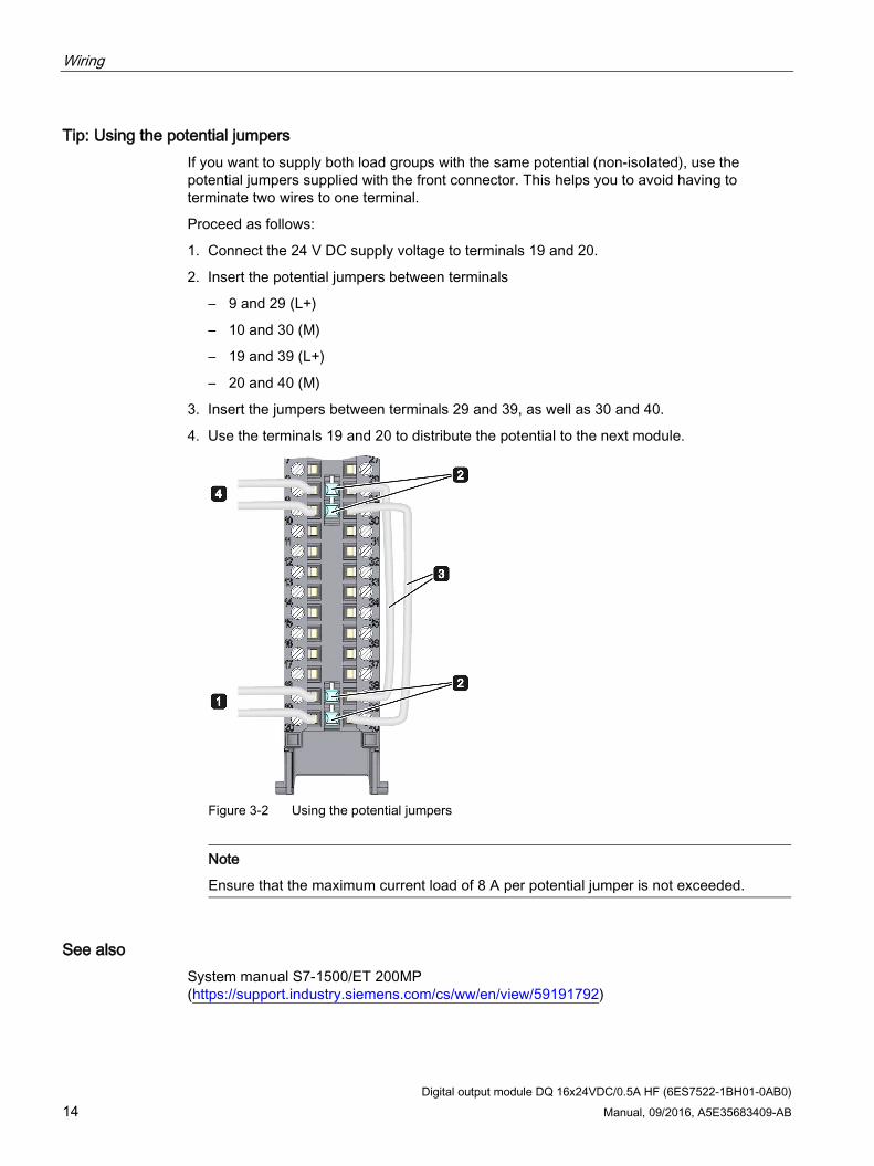
Tip: Using the potential jumpers If you want to supply both load groups with the same potential (non-isolated), use the potential jumpers supplied with the front connector. This helps you to avoid having to terminate two wires to one terminal.
Proceed as follows:
1. Connect the 24 V DC supply voltage to terminals 19 and 20.
2. Insert the potential jumpers between terminals
– 9 and 29 (L+)
– 10 and 30 (M)
– 19 and 39 (L+)
– 20 and 40 (M)
3. Insert the jumpers between terminals 29 and 39, as well as 30 and 40.
4. Use the terminals 19 and 20 to distribute the potential to the next module.
Figure 3-2 Using the potential jumpers
Note
Ensure that the maximum current load of 8 A per potential jumper is not exceeded.
See also System manual S7-1500/ET 200MP (https://support.industry.siemens.com/cs/ww/en/view/59191792)
Digital output module DQ 16x24VDC/0.5A HF (6ES7522-1BH01-0AB0) 15 Manual, 09/2016, A5E35683409-AB
Parameters/address space 4 4.1 Parameters
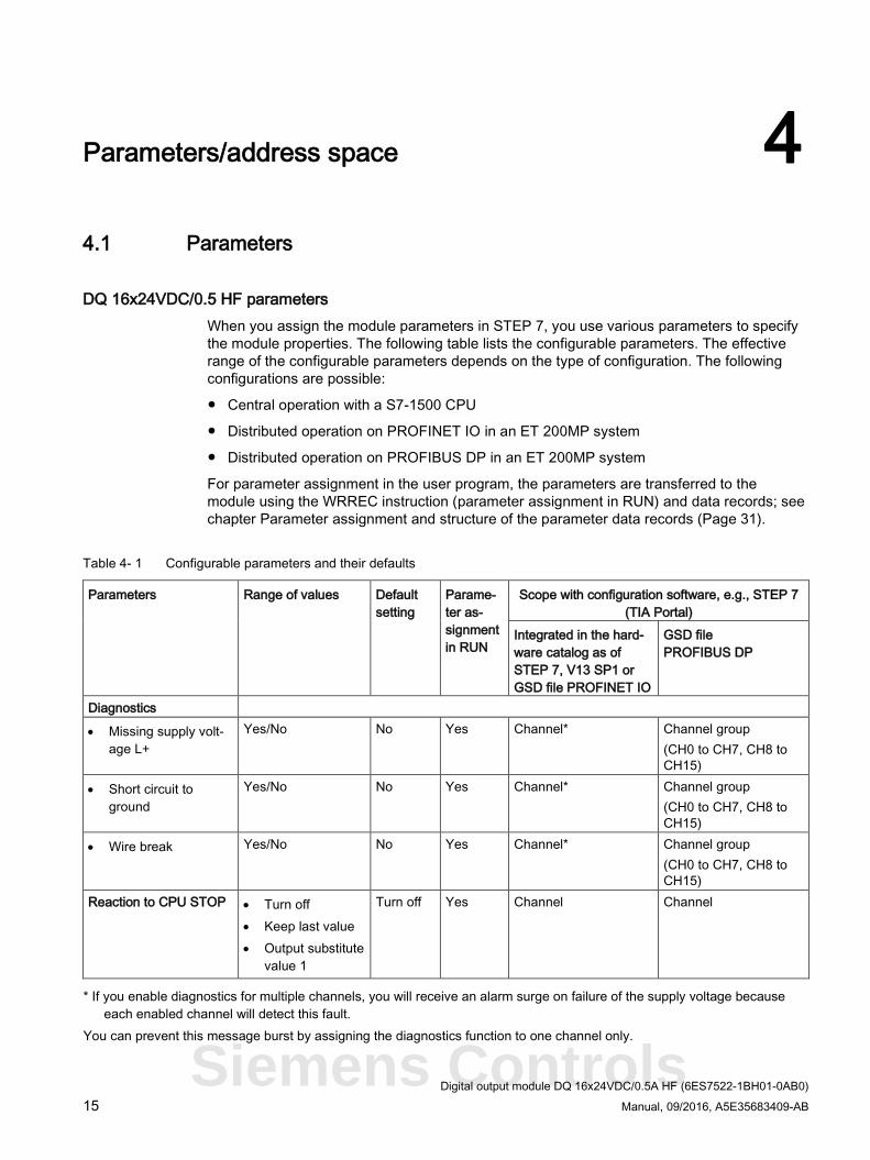
DQ 16x24VDC/0.5 HF parameters When you assign the module parameters in STEP 7, you use various parameters to specify the module properties. The following table lists the configurable parameters. The effective range of the configurable parameters depends on the type of configuration. The following configurations are possible:
● Central operation with a S7-1500 CPU
● Distributed operation on PROFINET IO in an ET 200MP system
● Distributed operation on PROFIBUS DP in an ET 200MP system
For parameter assignment in the user program, the parameters are transferred to the module using the WRREC instruction (parameter assignment in RUN) and data records; see chapter Parameter assignment and structure of the parameter data records (Page 31).
Table 4- 1 Configurable parameters and their defaults
Parameters Range of values Default setting
Parame-ter as-signment in RUN
Scope with configuration software, e.g., STEP 7 (TIA Portal)
Integrated in the hard-ware catalog as of STEP 7, V13 SP1 or GSD file PROFINET IO
GSD file PROFIBUS DP
Diagnostics
• Missing supply volt-age L+
Yes/No No Yes Channel* Channel group (CH0 to CH7, CH8 to CH15)
• Short circuit to ground
Yes/No No Yes Channel* Channel group (CH0 to CH7, CH8 to CH15)
• Wire break Yes/No No Yes Channel* Channel group (CH0 to CH7, CH8 to CH15)
Reaction to CPU STOP • Turn off • Keep last value • Output substitute
value 1
Turn off Yes Channel Channel
* If you enable diagnostics for multiple channels, you will receive an alarm surge on failure of the supply voltage because each enabled channel will detect this fault.
You can prevent this message burst by assigning the diagnostics function to one channel only.
Siemens Controls
Parameters/address space 4.2 Description of parameters
Digital output module DQ 16x24VDC/0.5A HF (6ES7522-1BH01-0AB0) 16 Manual, 09/2016, A5E35683409-AB
4.2 Description of parameters
No supply voltage Enabling of the diagnostics, for lacking or insufficient supply voltage L+.
Short circuit to ground Enabling of the diagnostics if a short-circuit of the actuator supply (CHx) to ground occurs.
Wire break Enabling of the diagnostics if the line to the actuator is broken.
Reaction to CPU STOP Determines the reaction of the output when the CPU goes into the STOP state or when the connection to the CPU is interrupted.
Parameters/address space 4.3 Address space
Digital output module DQ 16x24VDC/0.5A HF (6ES7522-1BH01-0AB0) Manual, 09/2016, A5E35683409-AB 17
4.3 Address space The module can be configured differently in STEP 7; see following table. Depending on the configuration, additional/different addresses are assigned in the process image of the outputs/inputs.
Configuration options of DQ 16x24VDC/0.5A HF You can configure the module with STEP 7 (TIA Portal) or with a GSD file.
When you configure the module by means of the GSD file, the configurations are available under different abbreviations/module names.
The following configurations are possible:
Table 4- 2 Configuration options
Configuration Short designation/module name in the GSD file
Configuration software, e.g., STEP 7 (TIA Por-tal)
Integrated in the hardware catalog
STEP 7 (TIA Portal) as of V13 SP1 with
HSP 0143
GSD file in STEP 7 (TIA Portal) V12
or higher or STEP 7 V5.5 SP3 or higher
1 x 16-channel without value status DQ 16x24VDC/0.5A HF X X 1 x 16-channel with value status DQ 16x24VDC/0.5A HF QI X X 2 x 8-channel without value status DQ 16x24VDC/0.5A HF S X
(PROFINET IO only) X
(PROFINET IO only) 2 x 8-channel with value status DQ 16x24VDC/0.5A HF S QI X
(PROFINET IO only) X
(PROFINET IO only) 1 x 16-channel with value status for module-internal Shared Output with up to 4 submodules
DQ 16x24VDC/0.5A HF MSO
X (PROFINET IO only)
X (PROFINET IO only)
Note Substitute value behavior in shared device mode with the following configuration: • 1 x 16-channel with value status for MSO • 1 x 16-channel with / without value status • 2 x 8-channel with / without value status
If the system is in shared device mode and one of the IO controllers involved goes into STOP or fails due to a communication failure, for example, all submodules of the output module perform the configured substitute value reaction (e.g. shutdown).
This means that even when only one IO controller fails, the other IO controllers associated with the shared device no longer control the assigned submodule of the output module.
Siemens Controls
Parameters/address space 4.3 Address space
Digital output module DQ 16x24VDC/0.5A HF (6ES7522-1BH01-0AB0) 18 Manual, 09/2016, A5E35683409-AB
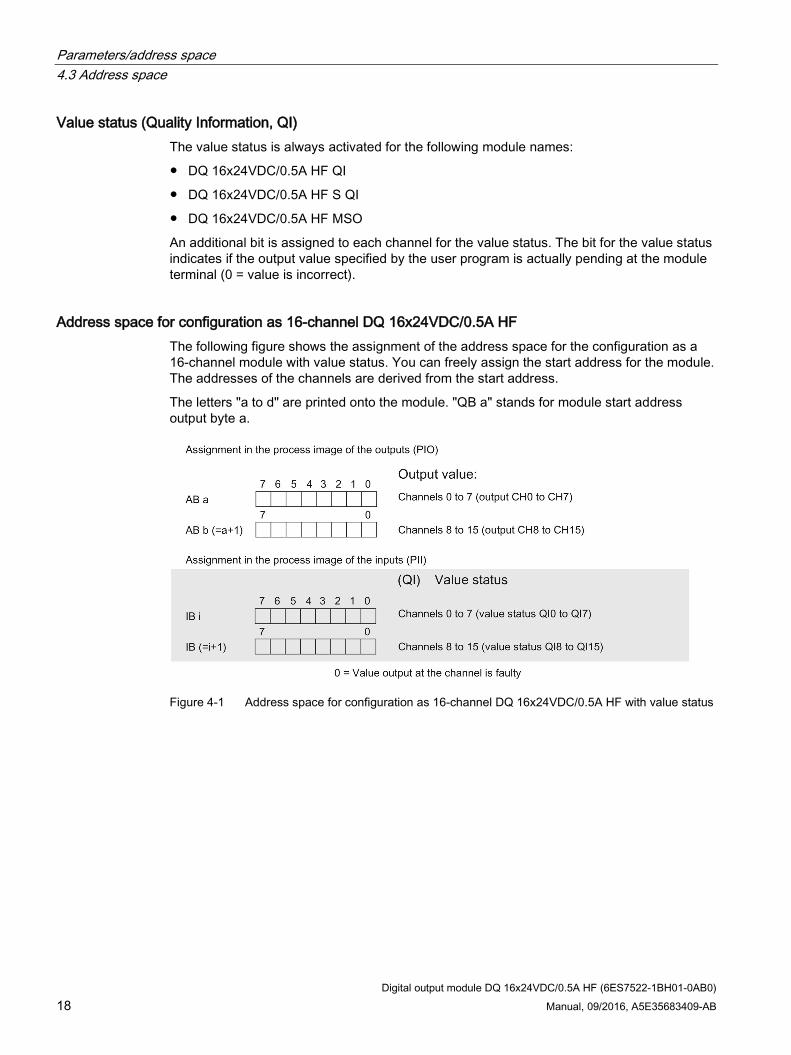
Value status (Quality Information, QI) The value status is always activated for the following module names:
● DQ 16x24VDC/0.5A HF QI
● DQ 16x24VDC/0.5A HF S QI
● DQ 16x24VDC/0.5A HF MSO
An additional bit is assigned to each channel for the value status. The bit for the value status indicates if the output value specified by the user program is actually pending at the module terminal (0 = value is incorrect).
Address space for configuration as 16-channel DQ 16x24VDC/0.5A HF The following figure shows the assignment of the address space for the configuration as a 16-channel module with value status. You can freely assign the start address for the module. The addresses of the channels are derived from the start address.
The letters "a to d" are printed onto the module. "QB a" stands for module start address output byte a.
Figure 4-1 Address space for configuration as 16-channel DQ 16x24VDC/0.5A HF with value status
Parameters/address space 4.3 Address space
Digital output module DQ 16x24VDC/0.5A HF (6ES7522-1BH01-0AB0) Manual, 09/2016, A5E35683409-AB 19
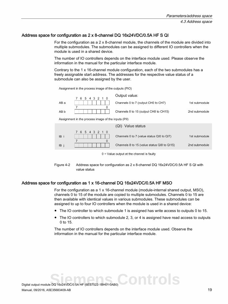
Address space for configuration as 2 x 8-channel DQ 16x24VDC/0.5A HF S QI For the configuration as a 2 x 8-channel module, the channels of the module are divided into multiple submodules. The submodules can be assigned to different IO controllers when the module is used in a shared device.
The number of IO controllers depends on the interface module used. Please observe the information in the manual for the particular interface module.
Contrary to the 1 x 16-channel module configuration, each of the two submodules has a freely assignable start address. The addresses for the respective value status of a submodule can also be assigned by the user.
Figure 4-2 Address space for configuration as 2 x 8-channel DQ 16x24VDC/0.5A HF S QI with
value status
Address space for configuration as 1 x 16-channel DQ 16x24VDC/0.5A HF MSO For the configuration as a 1 x 16-channel module (module-internal shared output, MSO), channels 0 to 15 of the module are copied to multiple submodules. Channels 0 to 15 are then available with identical values in various submodules. These submodules can be assigned to up to four IO controllers when the module is used in a shared device:
● The IO controller to which submodule 1 is assigned has write access to outputs 0 to 15.
● The IO controllers to which submodule 2, 3, or 4 is assigned have read access to outputs 0 to 15.
The number of IO controllers depends on the interface module used. Observe the information in the manual for the particular interface module.
Siemens Controls
Parameters/address space 4.3 Address space
Digital output module DQ 16x24VDC/0.5A HF (6ES7522-1BH01-0AB0) 20 Manual, 09/2016, A5E35683409-AB
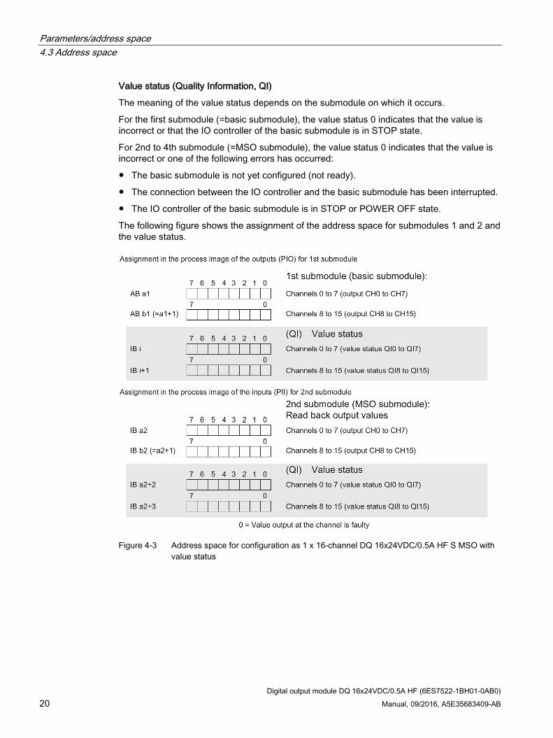
Value status (Quality Information, QI)
The meaning of the value status depends on the submodule on which it occurs.
For the first submodule (=basic submodule), the value status 0 indicates that the value is incorrect or that the IO controller of the basic submodule is in STOP state.
For 2nd to 4th submodule (=MSO submodule), the value status 0 indicates that the value is incorrect or one of the following errors has occurred:
● The basic submodule is not yet configured (not ready).
● The connection between the IO controller and the basic submodule has been interrupted.
● The IO controller of the basic submodule is in STOP or POWER OFF state.
The following figure shows the assignment of the address space for submodules 1 and 2 and the value status.
Figure 4-3 Address space for configuration as 1 x 16-channel DQ 16x24VDC/0.5A HF S MSO with
value status
Parameters/address space 4.3 Address space
Digital output module DQ 16x24VDC/0.5A HF (6ES7522-1BH01-0AB0) Manual, 09/2016, A5E35683409-AB 21
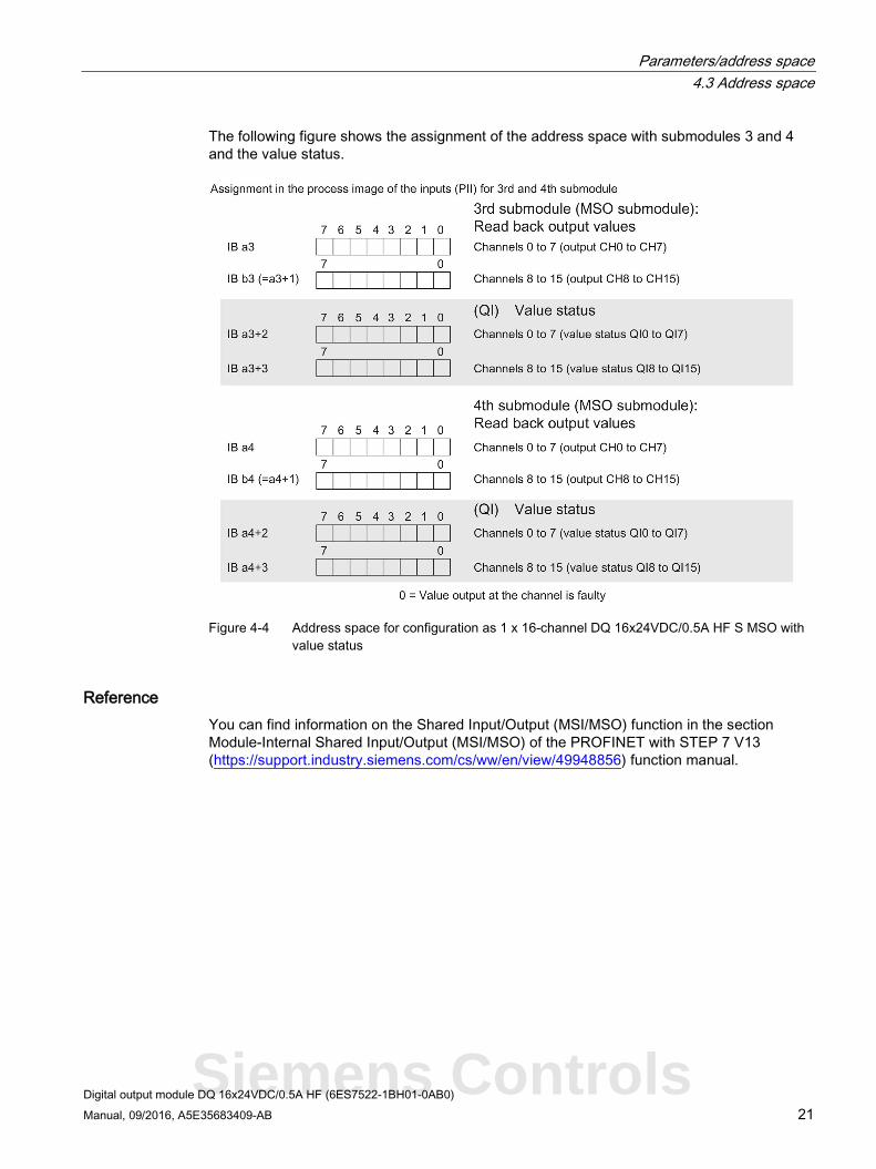
The following figure shows the assignment of the address space with submodules 3 and 4 and the value status.
Figure 4-4 Address space for configuration as 1 x 16-channel DQ 16x24VDC/0.5A HF S MSO with
value status
Reference You can find information on the Shared Input/Output (MSI/MSO) function in the section Module-Internal Shared Input/Output (MSI/MSO) of the PROFINET with STEP 7 V13 (https://support.industry.siemens.com/cs/ww/en/view/49948856) function manual.
Siemens Controls
Digital output module DQ 16x24VDC/0.5A HF (6ES7522-1BH01-0AB0) Manual, 09/2016, A5E35683409-AB 22
Interrupts/diagnostics alarms 5 5.1 Status and error displays
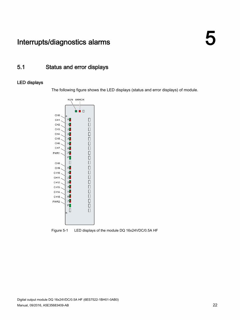
LED displays The following figure shows the LED displays (status and error displays) of module.
Figure 5-1 LED displays of the module DQ 16x24VDC/0.5A HF
Interrupts/diagnostics alarms 5.1 Status and error displays
Digital output module DQ 16x24VDC/0.5A HF (6ES7522-1BH01-0AB0) Manual, 09/2016, A5E35683409-AB 23
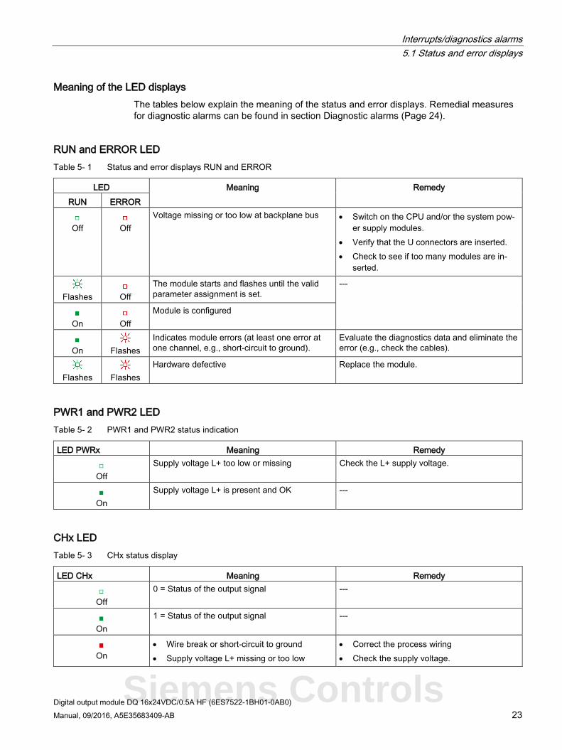
Meaning of the LED displays The tables below explain the meaning of the status and error displays. Remedial measures for diagnostic alarms can be found in section Diagnostic alarms (Page 24).
RUN and ERROR LED Table 5- 1 Status and error displays RUN and ERROR
LED Meaning Remedy RUN ERROR
Off
Off
Voltage missing or too low at backplane bus • Switch on the CPU and/or the system pow-er supply modules.
• Verify that the U connectors are inserted. • Check to see if too many modules are in-
serted.
Flashes
Off
The module starts and flashes until the valid parameter assignment is set.
---
On
Off
Module is configured
On
Flashes
Indicates module errors (at least one error at one channel, e.g., short-circuit to ground).
Evaluate the diagnostics data and eliminate the error (e.g., check the cables).
Flashes
Flashes
Hardware defective Replace the module.
PWR1 and PWR2 LED Table 5- 2 PWR1 and PWR2 status indication
LED PWRx Meaning Remedy
Off
Supply voltage L+ too low or missing Check the L+ supply voltage.
On
Supply voltage L+ is present and OK ---
CHx LED Table 5- 3 CHx status display
LED CHx Meaning Remedy
Off
0 = Status of the output signal ---
On
1 = Status of the output signal ---
On
• Wire break or short-circuit to ground • Supply voltage L+ missing or too low
• Correct the process wiring • Check the supply voltage.
Siemens Controls
Interrupts/diagnostics alarms 5.2 Interrupts
Digital output module DQ 16x24VDC/0.5A HF (6ES7522-1BH01-0AB0) 24 Manual, 09/2016, A5E35683409-AB
5.2 Interrupts Digital output module DQ 16x24VDC/0.5A HF supports diagnostic interrupts.
You can find detailed information on the event in the error organization block with the "RALRM" instruction (read additional interrupt info) and in the STEP 7 online help.
Diagnostic interrupt The module generates a diagnostic interrupt at the following events:
● Missing supply voltage L+
● Short circuit to ground
● Wire break
● Parameter assignment error
5.3 Diagnostics alarms
Diagnostics alarms A diagnostics alarm is generated and the ERROR LED flashes for each diagnostics event on the module. You can read the diagnostics alarms, for example, in the diagnostics buffer of the CPU. You can evaluate the error codes with the user program.
If the module is operated distributed with PROFIBUS DP in an ET 200MP system, you have the option to read out diagnostics data with the instruction RDREC or RD_REC using data record 0 and 1. The structure of the data records is available on the Internet in the "Manual for interface module IM 155-5 DP ST (6ES7155-5BA00-0AB0)".
Table 5- 4 Diagnostics alarms, their meaning and corrective measures
Diagnostics alarm Error code Meaning Corrective measures Short circuit to ground
1H Short-circuit or overload at the channel
Check the wiring/actuator. Check the ambient temperature.
Wire break* 6H Actuator circuit impedance too high. Use different actuator type or wire differently, e.g. use lines with bigger cross-section
Wire break between the module and actuator
Connect the cable
Channel not connected (open) • Disable diagnostics • Connect a resistor to the actuator contacts
in the load resistance range
Parameter assign-ment error
10H • The module cannot evaluate parameters for the channel.
• Incorrect parameter assignment
Correct the parameter assignment
Load voltage missing 11H Supply voltage L+ of the module is missing
Connect supply voltage L+ to module/channel
* Wire break is also reported for short-circuit of actuator supply to L+. This can lead to inappropriate diagnostics for redun-dant load control.
Digital output module DQ 16x24VDC/0.5A HF (6ES7522-1BH01-0AB0) 25 Manual, 09/2016, A5E35683409-AB
Technical specifications 6
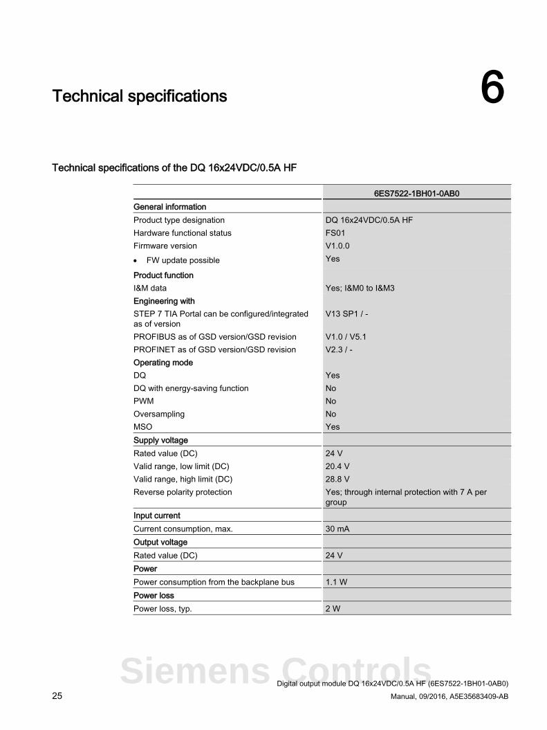
Technical specifications of the DQ 16x24VDC/0.5A HF
6ES7522-1BH01-0AB0 General information Product type designation DQ 16x24VDC/0.5A HF Hardware functional status FS01 Firmware version V1.0.0 • FW update possible Yes
Product function I&M data Yes; I&M0 to I&M3 Engineering with STEP 7 TIA Portal can be configured/integrated as of version
V13 SP1 / -
PROFIBUS as of GSD version/GSD revision V1.0 / V5.1 PROFINET as of GSD version/GSD revision V2.3 / - Operating mode DQ Yes DQ with energy-saving function No PWM No Oversampling No MSO Yes Supply voltage Rated value (DC) 24 V Valid range, low limit (DC) 20.4 V Valid range, high limit (DC) 28.8 V Reverse polarity protection Yes; through internal protection with 7 A per
group Input current Current consumption, max. 30 mA Output voltage Rated value (DC) 24 V Power Power consumption from the backplane bus 1.1 W Power loss Power loss, typ. 2 W
Siemens Controls
Technical specifications
Digital output module DQ 16x24VDC/0.5A HF (6ES7522-1BH01-0AB0) 26 Manual, 09/2016, A5E35683409-AB
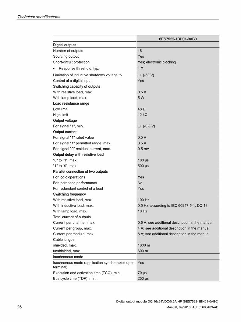
6ES7522-1BH01-0AB0 Digital outputs Number of outputs 16 Sourcing output Yes Short-circuit protection Yes; electronic clocking • Response threshold, typ. 1 A
Limitation of inductive shutdown voltage to L+ (-53 V) Control of a digital input Yes Switching capacity of outputs With resistive load, max. 0.5 A With lamp load, max. 5 W Load resistance range Low limit 48 Ω High limit 12 kΩ Output voltage For signal "1", min. L+ (-0.8 V) Output current For signal "1" rated value 0.5 A For signal "1" permitted range, max. 0.5 A For signal "0" residual current, max. 0.5 mA Output delay with resistive load "0" to "1", max. 100 µs "1" to "0", max. 500 µs Parallel connection of two outputs For logic operations Yes For increased performance No For redundant control of a load Yes Switching frequency With resistive load, max. 100 Hz With inductive load, max. 0.5 Hz; according to IEC 60947-5-1, DC-13 With lamp load, max. 10 Hz Total current of outputs Current per channel, max. 0.5 A; see additional description in the manual Current per group, max. 4 A; see additional description in the manual Current per module, max. 8 A; see additional description in the manual Cable length shielded, max. 1000 m unshielded, max. 600 m Isochronous mode Isochronous mode (application synchronized up to terminal)
Yes
Execution and activation time (TCO), min. 70 µs Bus cycle time (TDP), min. 250 µs
Technical specifications
Digital output module DQ 16x24VDC/0.5A HF (6ES7522-1BH01-0AB0) Manual, 09/2016, A5E35683409-AB 27
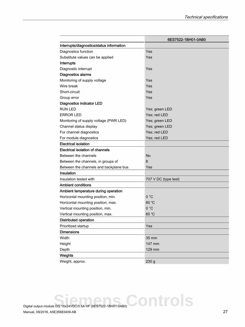
6ES7522-1BH01-0AB0 Interrupts/diagnostics/status information Diagnostics function Yes Substitute values can be applied Yes Interrupts Diagnostic interrupt Yes Diagnostics alarms Monitoring of supply voltage Yes Wire break Yes Short-circuit Yes Group error Yes Diagnostics indicator LED RUN LED Yes; green LED ERROR LED Yes; red LED Monitoring of supply voltage (PWR LED) Yes; green LED Channel status display Yes; green LED For channel diagnostics Yes; red LED For module diagnostics Yes; red LED Electrical isolation Electrical isolation of channels Between the channels No Between the channels, in groups of 8 Between the channels and backplane bus Yes Insulation Insulation tested with 707 V DC (type test) Ambient conditions Ambient temperature during operation Horizontal mounting position, min. 0 °C Horizontal mounting position, max. 60 ℃ Vertical mounting position, min. 0 °C Vertical mounting position, max. 60 ℃ Distributed operation Prioritized startup Yes Dimensions Width 35 mm Height 147 mm Depth 129 mm Weights Weight, approx. 230 g
Siemens Controls
Technical specifications
Digital output module DQ 16x24VDC/0.5A HF (6ES7522-1BH01-0AB0) 28 Manual, 09/2016, A5E35683409-AB
Residual current at signal state "0":
Note
Due to the Diagnostics: Wire break function, there is a low level of residual current in the "0" signal state at the output, which may cause the display diodes to flicker.
This residual current does not depend on the setting for the wire break diagnostics parameter.
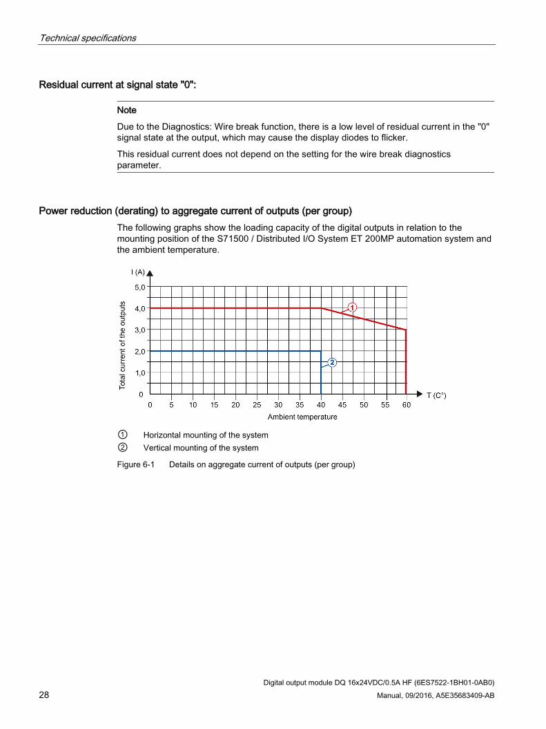
Power reduction (derating) to aggregate current of outputs (per group) The following graphs show the loading capacity of the digital outputs in relation to the mounting position of the S71500 / Distributed I/O System ET 200MP automation system and the ambient temperature.
① Horizontal mounting of the system ② Vertical mounting of the system
Figure 6-1 Details on aggregate current of outputs (per group)
Digital output module DQ 16x24VDC/0.5A HF (6ES7522-1BH01-0AB0) 29 Manual, 09/2016, A5E35683409-AB
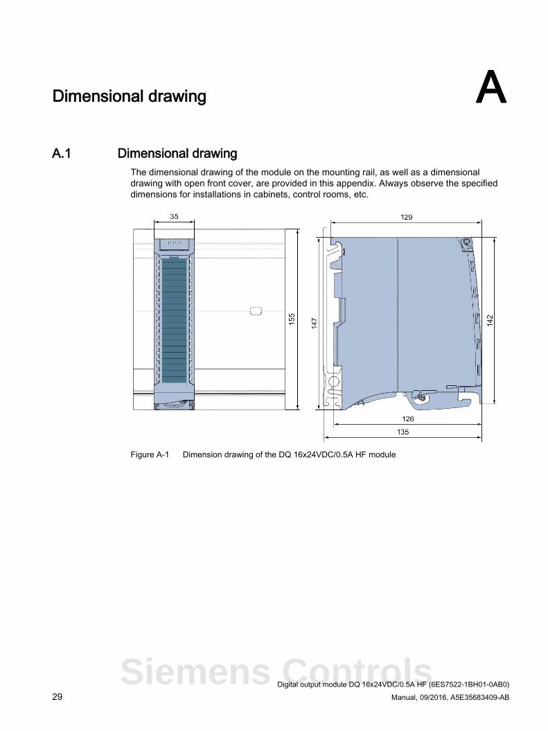
Dimensional drawing A A.1 Dimensional drawing
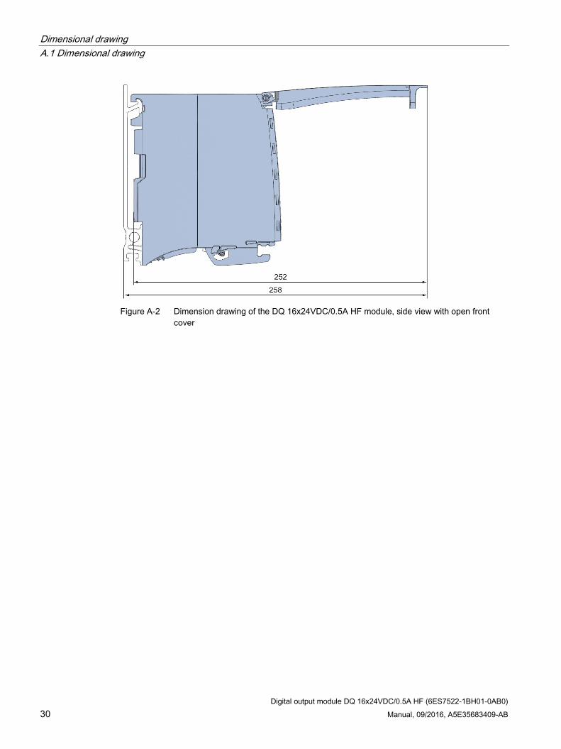
The dimensional drawing of the module on the mounting rail, as well as a dimensional drawing with open front cover, are provided in this appendix. Always observe the specified dimensions for installations in cabinets, control rooms, etc.
Figure A-1 Dimension drawing of the DQ 16x24VDC/0.5A HF module
Siemens Controls
Dimensional drawing A.1 Dimensional drawing
Digital output module DQ 16x24VDC/0.5A HF (6ES7522-1BH01-0AB0) 30 Manual, 09/2016, A5E35683409-AB
Figure A-2 Dimension drawing of the DQ 16x24VDC/0.5A HF module, side view with open front
cover
Digital output module DQ 16x24VDC/0.5A HF (6ES7522-1BH01-0AB0) 31 Manual, 09/2016, A5E35683409-AB
Parameter data records B B.1 Parameter assignment and structure of the parameter data records
The data records of the module have an identical structure, regardless of whether you configure the module with PROFIBUS DP or PROFINET IO.
Dependencies for configuration with GSD file When a GSD file is used to configure a module, dependencies can arise when "assigning the parameters".
There are no dependencies for this module. You can assign the individual parameters in any combination.
Parameter assignment in the user program You have the option to reconfigure the modules in RUN (e.g. the response of selected channels to the CPU-STOP state can be changed in RUN without having an effect on the other channels)
Parameter assignment in RUN The WRREC instruction is used to transfer the parameters to the module using data records 64 to 79. The parameters set in STEP 7 do not change in the CPU, which means the parameters set in STEP 7 are still valid after a restart.
The parameters are only checked for plausibility by the module after the transfer.
Output parameter STATUS The module ignores errors that occurred during the transfer of parameters with the WRREC instruction and continues operation with the previous parameter assignment. However, a corresponding error code is written to the STATUS output parameter.
The description of the WRREC instruction and the error codes is available in the STEP 7 online help.
Siemens Controls
Parameter data records B.1 Parameter assignment and structure of the parameter data records
Digital output module DQ 16x24VDC/0.5A HF (6ES7522-1BH01-0AB0) 32 Manual, 09/2016, A5E35683409-AB
Assignment of data record and channel For the configuration as a 1 x 16-channel module, the parameters are located in data records 64 to 79 and are assigned as follows:
● Data record 64 for channel 0
● Data record 65 for channel 1
● …
● Data record 78 for channel 14
● Data record 79 for channel 15
For the configuration as a 2 x 8-channel module, the module has 2 submodules with eight channels each. The parameters for the channels are located in data records 64 to 71 and are assigned as follows:
● Data records 64 to 71 for channels 0 to 7 (submodule 1)
● Data records 64 to 71 for channels 8 to 15 (submodule 2)
Address the respective submodule for data record transfer.
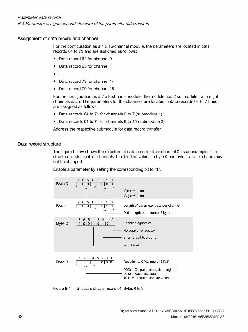
Data record structure The figure below shows the structure of data record 64 for channel 0 as an example. The structure is identical for channels 1 to 15. The values in byte 0 and byte 1 are fixed and may not be changed.
Enable a parameter by setting the corresponding bit to "1".
Figure B-1 Structure of data record 64: Bytes 0 to 3
Recommended