Embed Size (px)
Citation preview
Acoplamientos Flexibles
13
4
Características generales DescripciónSelecciónMontaje de los acoplamientos UNE-FLEX 8
Amortiguación - Rigidez torsional 9
10Acoplamiento para eje directo Acoplamiento para Eje Directo Serie M Acoplamiento para Eje Directo Serie 1 Acoplamiento para Eje Directo Serie DVAAcoplamiento para Eje Directo Serie FF
14Acoplamiento para casquillo cónico Acoplamiento con casquillo cónico Serie T Acoplamiento con casquillo cónico Serie FAcoplamiento con casquillo cónico Serie DVSCasquillos cónicos
18Acoplamiento para frenoAcoplamiento con Polea de freno Serie P Acoplamiento con Disco de Freno Serie D
22Acoplamiento con espaciador Acoplamiento con espaciador Serie MTD Acoplamiento con espaciador Serie SDAcoplamiento con Espaciador Serie FTD
Flexible couplings
General Characteristics DescriptionSelectionCoupling Assembly UNE-FLEX
Damping Isolation - Dynamic Torsional Stiffness
Shaft to shaft couplingShaft to shaft coupling M Series Shaft to shaft coupling 1 Series Shaft to shaft coupling DVA SeriesShaft to shaft coupling FF Series
Coupling with conical bushing Coupling with conical bushing T Series Coupling with conical bushing F SeriesCoupoling with conical bushig DVS SeriesConical Bushings
Coupling for brakeCouplings with Pulley brake P Series Coupling with Disc Brake D Series
Spacer coupling Spacer coupling MTD Series Spacer coupling SD SeriesSpacer coupling FTD Series
General CharacteristicsCaracterísticas generales
1
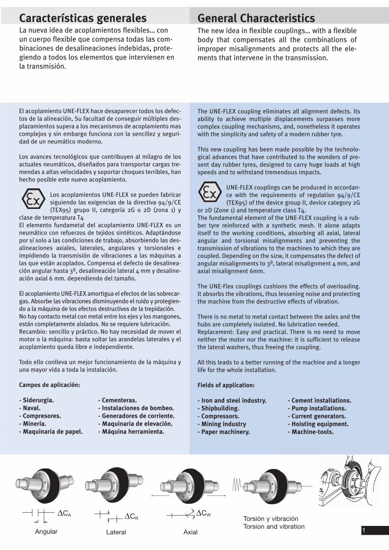
El acoplamiento UNE-FLEX hace desaparecer todos los defec-tos de la alineación, Su facultad de conseguir múltiples des-plazamientos supera a los mecanismos de acoplamiento mascomplejos y sin embargo funciona con la sencillez y seguri-dad de un neumático moderno.
Los avances tecnológicos que contribuyen al milagro de losactuales neumáticos, diseñados para transportar cargas tre-mendas a altas velocidades y soportar choques terribles, hanhecho posible este nuevo acoplamiento.
Los acoplamientos UNE-FLEX se pueden fabricarsiguiendo las exigencias de la directiva 94/9/CE(TEX95) grupo II, categoría 2G o 2D (zona 1) y
clase de temperatura T4El elemento fundametal del acoplamiento UNE-FLEX es unneumático con refuerzos de tejidos sintéticos. Adaptándosepor sí solo a las condiciones de trabajo, absorbiendo las des-alineaciones axiales, laterales, angulares y torsionales eimpidiendo la transmisión de vibraciones a las máquinas alas que están acoplados. Compensa el defecto de desalinea-ción angular hasta 3º, desalineación lateral 4 mm y desaline-ación axial 6 mm. dependiendo del tamaño.
El acoplamiento UNE-FLEX amortigua el efectos de las sobrecar-gas. Absorbe las vibraciones disminuyendo el ruido y protegien-do a la máquina de los efectos destructivos de la trepidación.No hay contacto metal con metal entre los ejes y los mangones,están completamente aislados. No se requiere lubricación.Recambio: sencillo y práctico. No hay necesidad de mover elmotor o la máquina: basta soltar las arandelas laterales y elacoplamiento queda libre e independiente.
Todo ello conlleva un mejor funcionamiento de la máquina yuna mayor vida a toda la instalación.
Campos de aplicación:
- Siderurgia.- Naval.- Compresores.- Minería.- Maquinaria de papel.
The UNE-FLEX coupling eliminates all alignment defects. Itsability to achieve multiple displacements surpasses morecomplex coupling mechanisms, and, nonetheless it operateswith the simplicity and safety of a modern rubber tyre.
This new coupling has been made possible by the technolo-gical advances that have contributed to the wonders of pre-sent day rubber tyres, designed to carry huge loads at highspeeds and to withstand tremendous impacts.
UNE-FLEX couplings can be produced in accordan-ce with the requirements of regulation 94/9/CE(TEX95) of the device group II, device category 2G
or 2D (Zone 1) and temperature class T4. The fundamental element of the UNE-FLEX coupling is a rub-ber tyre reinforced with a synthetic mesh. It alone adaptsitself to the working conditions, absorbing all axial, lateralangular and torsional misalignments and preventing thetransmission of vibrations to the machines to which they arecoupled. Depending on the sizw, it compensates the defect ofangular misalignments to 3º, lateral misalignment 4 mm, andaxial misalignment 6mm.
The UNE-Flex couplings cushions the effects of overloading.It absorbs the vibrations, thus lessening noise and protectingthe machine from the destructive effects of vibration.
There is no metal to metal contact between the axles and thehubs are completely isolated. No lubrication needed.Replacement: Easy and practical. There is no need to moveneither the motor nor the machine: it is sufficient to releasethe lateral washers, thus freeing the coupling.
All this leads to a better running of the machine and a longerlife for the whole installation.
Fields of application:
- Iron and steel industry.- Shipbuilding.- Compressors.- Mining industry- Paper machinery.
The new idea in flexible couplings… with a flexiblebody that compensates all the combinations ofimproper misalignments and protects all the ele-ments that intervene in the transmission.
La nueva idea de acoplamientos flexibles… conun cuerpo flexible que compensa todas las com-binaciones de desalineaciones indebidas, prote-giendo a todos los elementos que intervienen enla transmisión.
Angular Lateral Axial
Torsión y vibraciónTorsion and vibration
�� ����
- Cement installations.- Pump installations.- Current generators.- Hoisting equipment.- Machine-tools.
- Cementeras.- Instalaciones de bombeo.- Generadores de corriente.- Maquinaria de elevación.- Máquina herramienta.
2
3
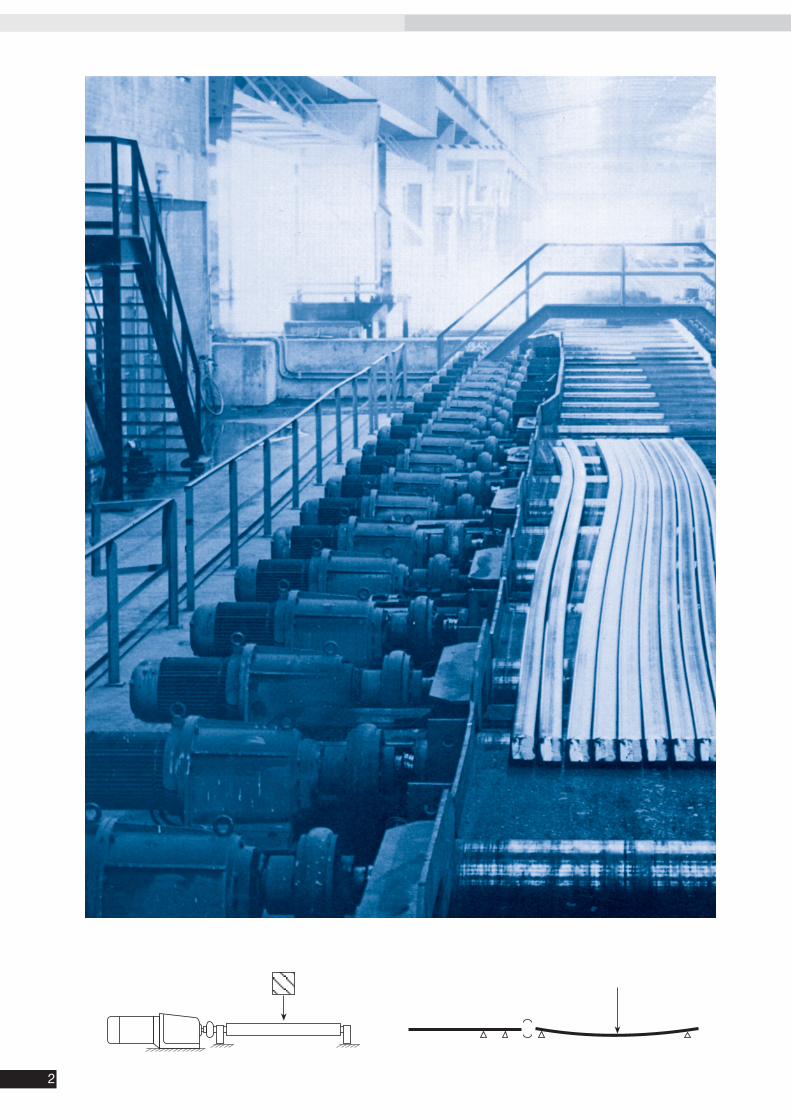
El acoplamiento UNE-FLEX se utiliza en el accionamientoindividual de los rodillos en el que es conveniente evitarcualquier transmisión abierta y utilizar en su lugar un aco-plamiento sin holgura, de alta elasticidad.
Accionamiento individual de un rodillo mediante acopla-miento UNE-FLEX sin juego, de alta elasticidad y motoreduc-tor para caminos de rodillos. En la disposición descrita seplantean una serie de importantes puntos de vista:-El acoplamiento intercalado impide la transmisión directadel calor desde el rodillo al reductor y al motor, de forma queno perjudica a la lubricación del reductor y al aislamiento delmotor.-Se eliminan o alejan considerablemente del accionamientolas trepidaciones y golpes al iniciar la marcha y sobre todo al“apoyar la carga” del material a transportar sobre el rodillo.-El pandeo del eje del rodillo, que se presenta frecuentemen-te en condiciones duras de trabajo, no tiene ninguna influen-cia perjudicial sobre el reductor.
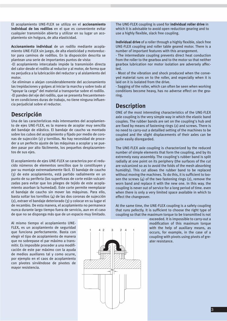
DescripciónUna de las características más interesantes del acoplamien-to de ejes UNE-FLEX, es la manera de acoplar muy sencilladel bandaje de elástico. El bandaje de caucho va montadosobre los cubos del acoplamiento y fijado por medio de coro-nas de sujección (2) y tornillos. No hay necesidad de proce-der a un perfecto ajuste de las máquinas a acoplar y se pue-den pasar por alto fácilmente, los pequeños desplazamien-tos de sus ejes.
El acoplamiento de ejes UNE-FLEX se caracteriza por el redu-cido números de elementos sencillos que lo constituyen ypor su montaje extremadamente fácil. El bandaje de caucho(3) de este acoplamiento, está partido radialmente en unpunto de su periferia (las superficeas de corte están vulcani-zadas para evitar que los plieges de tejido de este acopla-miento asorban la humedad). Este corte permite reemplazarel bandaje de caucho sin mover las máquinas. Para ello,basta soltar los tornillos (4) de las dos coronas de sujección(2), extraer el bandaje deteriorado (3) y colocar en su lugar elde recambio. De esta manera, el acoplamiento no permanecenunca durante largo tiempo fuera de servicio, aun en el casode que no se disponga más que de un espacio muy limitado.
Al mismo tiempo el acoplamiento UNE-FLEX, es un acoplamiento de seguridadque funciona perfectamente. Basta conelegir el tipo de acoplamiento de maneraque no sobrepase el par máximo a trans-mitir. Es imposible proceder a una modifi-cación de este par máximo con la ayudade medios auxiliares tal y como ocurre,por ejemplo en el caos de acoplamientocon pivotes sirviéndose de pivotes demayor resistencia.
The UNE-FLEX coupling is used for individual roller drive inwhich it is advisable to avoid open reduction gearing and touse a highly flexible, slack free coupling.
Individual drive of a roller through a highly flexible, slack freeUNE-FLEX coupling and roller table geared motor. There is anumber of important features with this arrangement.- The intermediate coupling prevents direct heat conductionfrom the roller to the gearbox and to the motor so that neithergearbox lubrication nor motor isolation are adversely affec-ted.- Most of the vibration and shock produced when the conve-yed material runs on to the roller, and especially when it islaid on it is isolated from the drive.- Sagging of the roller, which can often be seen when workingconditions become heavy, has no adverse effect on the gea-ring.
DescriptionONE of the most interesting characteristics of the UNE-FLEXaxle coupling is the very simple way in which the elastic bandcouples. The rubber bands are set on the coupling's hub andare fixed by means of fastening rings (2) and screws. There isno need to carry-out a detailled setting of the machines to becoupled and the slight displacements of their axles can bequite easily disregarded.
The UNE-FLEX axle coupling is characterized by the reducednumber of simple elements that form the coupling, and by itsextremely easy assembly. The coupling's rubber band is splitradially at one point on its periphery (the surfaces of the cutare vulcanized so as to avoid the folds of the mesh absorbinghumidity). This cut allows the rubber band to be replacedwithout moving the machines. To do this, it is sufficient to loo-sen the screws (4) of the two fastening rings (2), remove theworn band and replace it with the new one. In this way. thecoupling is never out of service for a long period of time. evenwhen there is only a very limited space available in which toeffect the changeover.
At the same time, the UNE-FLEX coupling is a safety couplingthat runs pefectly. It is sufficient to choose the right type ofcoupling so that the maximum torque to be transmitted is not
exceeded. It is impossible to carry-out amodification of this maximum torquewith the help of auxiliary means, asoccurs, for example, in the case of acoupling with pivots using pivots of gre-ater resistance.
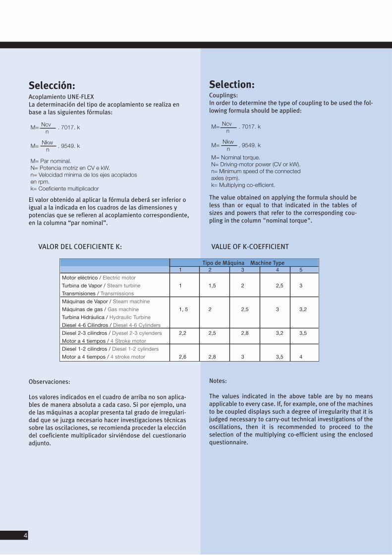
Selection:Couplings:In order to determine the type of coupling to be used the fol-lowing formula should be applied:
Selección:Acoplamiento UNE-FLEXLa determinación del tipo de acoplamiento se realiza enbase a las siguientes fórmulas:
VALOR DEL COEFICIENTE K: VALUE OF K-COEFFICIENT
Tipo de Máquina Machine Type1 2 3 4 5
Motor eléctrico / Electric motor
Turbina de Vapor / Steam turbine 1 1,5 2 2,5 3
Transmisiones / Transmissions
Máquinas de Vapor / Steam machine
Máquinas de gas / Gas machine 1, 5 2 2,5 3 3,2
Turbina Hidráulica / Hydraulic Turbine
Diesel 4-6 Cilindros / Diesel 4-6 Cylinders
Diesel 2-3 cilindros / Dyesel 2-3 cylenders 2,2 2,5 2,8 3,2 3,5
Motor a 4 tiempos / 4 Stroke motor
Diesel 1-2 cilindros / Diesel 1-2 cylinders
Motor a 4 tiempos / 4 stroke motor 2,6 2,8 3 3,5 4
Observaciones:
Los valores indicados en el cuadro de arriba no son aplica-bles de manera absoluta a cada caso. Si por ejemplo, unade las máquinas a acoplar presenta tal grado de irregulari-dad que se juzga necesario hacer investigaciones técnicassobre las oscilaciones, se recomienda proceder la eleccióndel coeficiente multiplicador sirviéndose del cuestionarioadjunto.
Notes:
The values indicated in the above table are by no meansapplicable to every case. If, for example, one of the machinesto be coupled displays such a degree of irregularity that it isjudged necessary to carry-out technical investigations of theoscillations, then it is recommended to proceed to the selection of the multiplying co-efficient using the enclosedquestionnaire.
El valor obtenido al aplicar la fórmula deberá ser inferior oigual a la indicada en los cuadros de las dimensiones ypotencias que se refieren al acoplamiento correspondiente,en la columna “par nominal”.
The value obtained on applying the formula should beless than or equal to that indicated in the tables ofsizes and powers that refer to the corresponding cou-pling in the column "nominal torque".
4
5
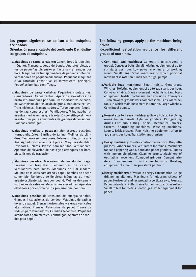
Los grupos siguientes se aplican a las máquinas accionadas:Orientación para el calculo del coeficiente K en distin-tos grupos de máquinas.
1. Máquinas de carga constante: Generadores (grupo elec-trógeno). Transportadoras de banda. Aparatos elevado-res de pequeñas dimensiones hasta seis arranques porhora. Máquinas de trabajar madera de pequeña potencia.Ventiladores de pequeña dimensión. Pequeñas máquinascuya rotación constituye el movimiento principal.Pequeñas bombas centrífugas.
2.Maquinas de carga variable: Pequeños montacargas.Generedores. Cabestrantes. Aparatos elevadores dehasta 120 arranques por hora. Transportadoras de cade-na. Mecanismo de traslación de grúas. Máquinas textiles.Transmisiones. Transportadores. Turbo-sopletes (sople-tes de gas: compresores). Ventiladores, Máquinas-herra-mientas medias en las que la rotación constituye el movi-miento principal. Cabestrantes de grandes dimensiones.Bombas centrífugas.
3.Máquinas medias y pesadas: Montacargas pesados.Hornos giratórios. Barriles de tanino. Molinos de cilin-dros. Tambores refrigeradores. Telares continuos de ani-llos. Agitadores mecánicos. Tijeras . Máquinas de afilar.Lavadoras. Telares. Prensa para ladrillos. Ventiladores.Aparatos de elevación de hasta 300 arranques por hora.Mecanismos de traslación.
4.Maquinas pesadas: Mecanismo de mando de draga.Prensas de briquetas. Laminadoras de caucho.Ventiladores para minas. Máquinas de lijar madera.Molinos de muelas para arena y papel. Bombas de pistónsumerjible. Tambores de limpieza. Máquinas de movi-miento oscilante. Molinos compound. Molinos de cemen-to. Bancos de estirage. Mecanismos elevadores. Aparatoselevadores por encima de los 300 arranque por hora.
5. Máquinas pesadas de consumo de energía variable.Grandes instalaciones de sondeo. Máquinas de satinarhojas de papel. Sierras horizontales y sierras verticalesalternativas. Prensas. Calandrias de papel. Trenes derodillos para laminadoras. Cilindros secadores. Pequeñaslaminadoras para metales. Centrífugas. Aparatos de rodi-llos para papel.
The following groups apply to the machines beingdriven:K-coefficient calculation guidance for differentgroups of machines.
1. Continual load machines: Generators (electrogeneticgroup). Conveyor belts. Small hoisting equipment of up tosix starts per hour. Low power machinery for workingwood. Small fans. Small machines of which principalmovement is rotation. Small centrifugal pumps.
2.Variable load machines: Small hoists. Generators.Winches. Hoisting equipment of up to 120 starts per hour.Conveyor chains. Crane movement mechanism. Sand blastequipment. Textile machinery. Transmissions. ConveyorsTurbo blowers (gas blowers:compressors). Fans. Machine-tools in which main movement is rotation. Large winches.Centrifugal pumps.
3.Normal size to heavy machinery: Heavy hoists. Revolvingovens Tannin barrels. Cylinder grinders. Refrigeratingdrums Continuous Ring Looms. Mechanical mixers.Cutters. Sharpening machines. Washing machines.Looms. Brick presses. Fans Hoisting equipment of up to300 starts per hour. Translation mechanism.
4.Heavy machinery: Dredge control mechanism. Briquettepresses. Rubber rollers. Ventilators for mines. Machineryfor sand papering wood. Sand and paper grinders. Pumpswith immersible piston. Cleaning drums. Machinery ofoscillating movement. Compoud grinders. Cement grin-ders. Drawbenches. Hoisting mechanisms. Hoistingequipment of more than 300 starts per hour.
5. Heavy machinery: of variable energy consumption: Largedrilling installations Machinery for glossing sheets ofpaper. Horizontal and reciprocating vertical saws. Presses.Paper calenders. Roller trains for laminators. Drier rollersSmall rollers for metals Centrifuges. Roller equipment forpaper.
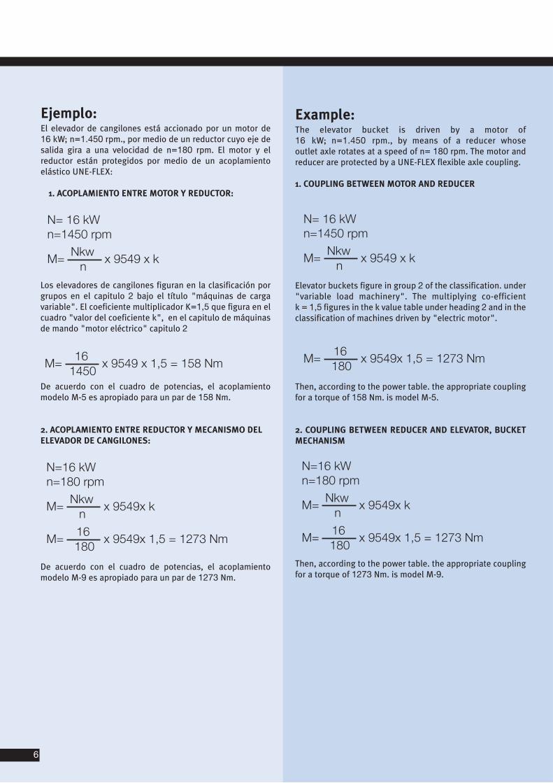
Example:The elevator bucket is driven by a motor of 16 kW; n=1.450 rpm., by means of a reducer whose outlet axle rotates at a speed of n= 180 rpm. The motor andreducer are protected by a UNE-FLEX flexible axle coupling.
1. COUPLING BETWEEN MOTOR AND REDUCER
Ejemplo:El elevador de cangilones está accionado por un motor de 16 kW; n=1.450 rpm., por medio de un reductor cuyo eje desalida gira a una velocidad de n=180 rpm. El motor y elreductor están protegidos por medio de un acoplamientoelástico UNE-FLEX:
1. ACOPLAMIENTO ENTRE MOTOR Y REDUCTOR:
Los elevadores de cangilones figuran en la clasificación porgrupos en el capitulo 2 bajo el título "máquinas de cargavariable". El coeficiente multiplicador K=1,5 que figura en elcuadro "valor del coeficiente k", en el capitulo de máquinasde mando "motor eléctrico" capitulo 2
De acuerdo con el cuadro de potencias, el acoplamientomodelo M-5 es apropiado para un par de 158 Nm.
2. ACOPLAMIENTO ENTRE REDUCTOR Y MECANISMO DELELEVADOR DE CANGILONES:
De acuerdo con el cuadro de potencias, el acoplamientomodelo M-9 es apropiado para un par de 1273 Nm.
Elevator buckets figure in group 2 of the classification. under"variable load machinery". The multiplying co-efficient k = 1,5 figures in the k value table under heading 2 and in theclassification of machines driven by "electric motor".
Then, according to the power table. the appropriate couplingfor a torque of 158 Nm. is model M-5.
2. COUPLING BETWEEN REDUCER AND ELEVATOR, BUCKETMECHANISM
Then, according to the power table. the appropriate couplingfor a torque of 1273 Nm. is model M-9.
6
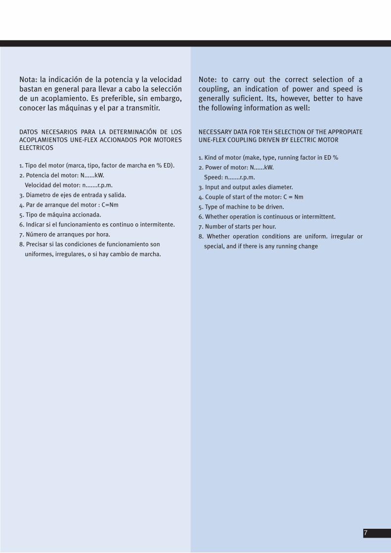
Nota: la indicación de la potencia y la velocidadbastan en general para llevar a cabo la selecciónde un acoplamiento. Es preferible, sin embargo,conocer las máquinas y el par a transmitir.
DATOS NECESARIOS PARA LA DETERMINACIÓN DE LOSACOPLAMIENTOS UNE-FLEX ACCIONADOS POR MOTORESELECTRICOS
1. Tipo del motor (marca, tipo, factor de marcha en % ED).
2. Potencia del motor: N......kW.
Velocidad del motor: n.......r.p.m.
3. Diametro de ejes de entrada y salida.
4. Par de arranque del motor : C=Nm
5. Tipo de máquina accionada.
6. Indicar si el funcionamiento es continuo o intermitente.
7. Número de arranques por hora.
8. Precisar si las condiciones de funcionamiento son
uniformes, irregulares, o si hay cambio de marcha.
Note: to carry out the correct selection of a coupling, an indication of power and speed isgenerally suficient. Its, however, better to havethe following information as well:
NECESSARY DATA FOR TEH SELECTION OF THE APPROPIATEUNE-FLEX COUPLING DRIVEN BY ELECTRIC MOTOR
1. Kind of motor (make, type, running factor in ED %
2. Power of motor: N......kW.
Speed: n.......r.p.m.
3. Input and output axles diameter.
4. Couple of start of the motor: C = Nm
5. Type of machine to be driven.
6. Whether operation is continuous or intermittent.
7. Number of starts per hour.
8. Whether operation conditions are uniform. irregular or
special, and if there is any running change
7
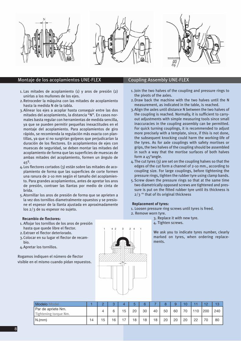
1. Join the two halves of the coupling and pressure rings tothe pivots of the axles.
2.Draw back the machine with the two halves until the Nmeasurement, as indicated in the table, is reached.
3.Align the axles until distance N between the two halves ofthe coupling is reached. Normally, it is sufficient to carry-out adjustments with simple measuring tools since smallinaccuracies in the coupling assembly can be permitted.For quick turning couplings, it is recommended to adjustmore precisely with a template, since, if this is not done,the subsequent knocking could harm the working-life ofthe tyres. As for axle couplings with safety mortises orgrips, the two halves of the coupling should be assembledin such a way that the mortise surfaces of both halvesform a 45°angle.
4.The cut tyres (3) are set on the coupling halves so that theedges of the cut form a channel of 2-10 mm., according tocoupling size. For large couplings, before tightening thepressure rings, tighten the rubber tyre using clamp bands.
5.Screw down the pressure rings so that at the same timetwo diametrically opposed screws are tightened and pres-sure is put on the fitted rubber tyre until its thickness is2/3 rds that of its original thickness
Replacement of tyres:1. Loosen pressure ring screws until tyres is freed.2. Remove worn tyre.
3. Replace it with new tyre.4. Tighten screws.
We ask you to indicate tyres number, clearlymarked on tyres, when ordering replace-ments.
1. Las mitades de acoplamiento (1) y aros de presión (2)unirlas a los muñones de los ejes.
2.Retroceder la máquina con las mitades de acoplamientohasta la medida N de la tabla.
3.Alinear los ejes a acoplar hasta conseguir entre las dosmitades del acoplamiento, la distancia “N”. En casos nor-males basta regular con herramientas de medida sencilla,ya que se pueden permitir pequeñas inexactitudes en elmontaje del acoplamiento. Para acoplamientos de girorápido, se recomienda la regulación más exacta con plan-tillas, ya que si no surgirían golpeos que perjudicarían laduración de los flectores. En acoplamientos de ejes conmuescas de seguridad, se deben montar las mitades delacoplamiento de forma que las superficies de muescas deambas mitades del acoplamiento, formen un ángulo de45º.
4.Los flectores cortados (3) están sobre las mitades de aco-plamiento de forma que las superficies de corte formenuna ranura de 2-10 mm según el tamaño del acoplamien-to. Para grandes acoplamientos, antes de apretar los arosde presión, contraer las llantas por medio de cinta debrida.
5.Atornillar los aros de presión de forma que se aprieten ala vez dos tornillos diametralmente opuestos y se presio-ne el espesor de la llanta ajustada en aproximadamentelos 2/3 de su espesor no sujeto.
Recambio de flectores:1. Aflojar los tornillos de los aros de presión
hasta que quede libre el flector.2.Extraer el flector deteriorado.3.Colocar en su lugar el flector de recam-
bio. 4.Apretar los tornillos.
Rogamos indiquen el número de flector visible en el mismo cuando pidan repuestos.
Montaje de los acoplamientos UNE-FLEX Coupling Assembly UNE-FLEX
Modelo Model 1 2 3 4 5 6 7 8 9 10 11 12 13Par de apriete Nm. 4 6 15 20 30 40 50 60 70 110 200 240Tightening torque Nm.
N.(mm) 14 15 16 17 18 18 18 20 20 20 22 70 80
8
9
Flector R Tyre R
Flector X Tyre X
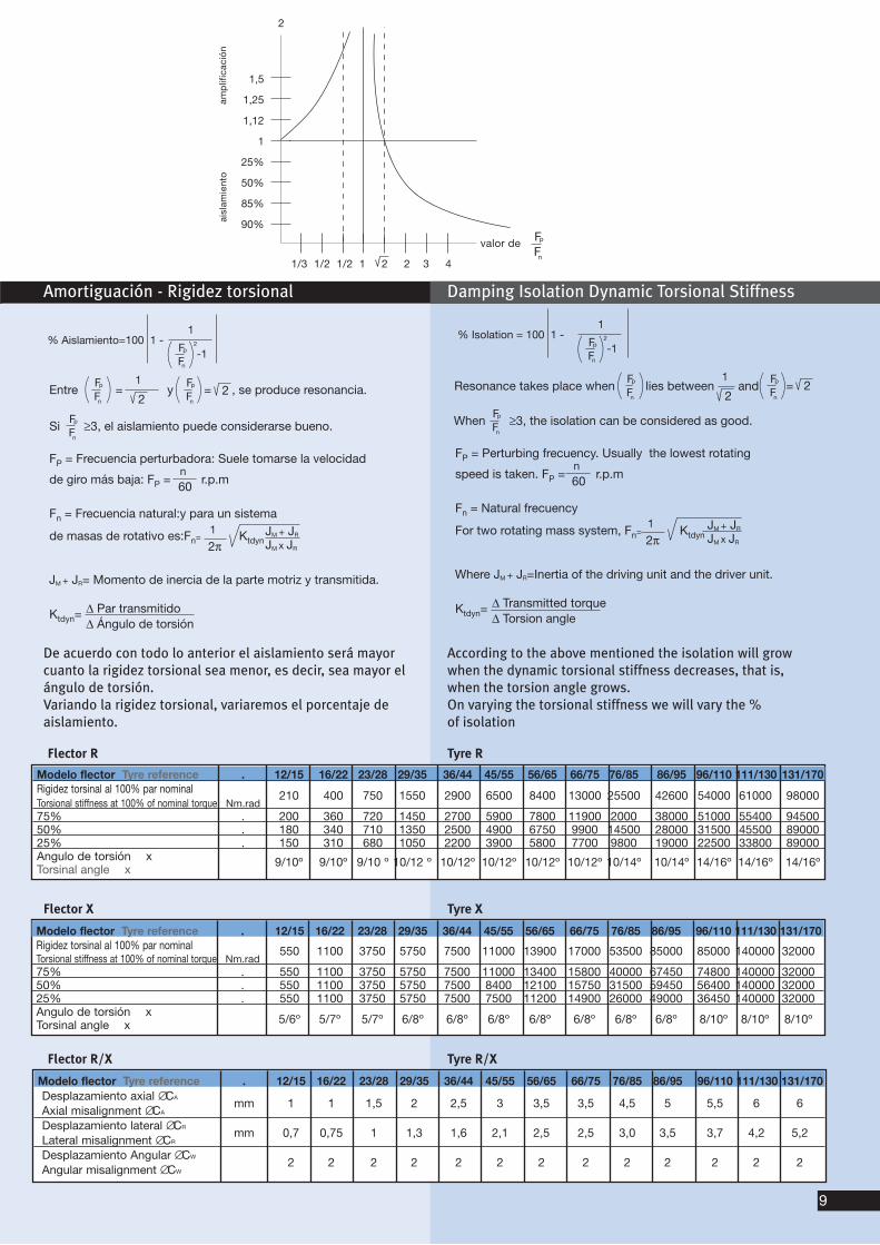
De acuerdo con todo lo anterior el aislamiento será mayorcuanto la rigidez torsional sea menor, es decir, sea mayor elángulo de torsión.Variando la rigidez torsional, variaremos el porcentaje deaislamiento.
According to the above mentioned the isolation will growwhen the dynamic torsional stiffness decreases, that is,when the torsion angle grows.On varying the torsional stiffness we will vary the % of isolation
Amortiguación - Rigidez torsional Damping Isolation Dynamic Torsional Stiffness
Flector R/X Tyre R/X
Modelo flector Tyre reference . 12/15 16/22 23/28 29/35 36/44 45/55 56/65 66/75 76/85 86/95 96/110 111/130 131/170 Rigidez torsinal al 100% par nominalTorsional stiffness at 100% of nominal torque Nm.rad
210 400 750 1550 2900 6500 8400 13000 25500 42600 54000 61000 98000
75% . 200 360 720 1450 2700 5900 7800 11900 2000 38000 51000 55400 94500 50% . 180 340 710 1350 2500 4900 6750 9900 14500 28000 31500 45500 89000 25% . 150 310 680 1050 2200 3900 5800 7700 9800 19000 22500 33800 89000Angulo de torsión x Torsinal angle x
9/10º 9/10º 9/10 º 10/12 º 10/12º 10/12º 10/12º 10/12º 10/14º 10/14º 14/16º 14/16º 14/16º
Modelo flector Tyre reference . 12/15 16/22 23/28 29/35 36/44 45/55 56/65 66/75 76/85 86/95 96/110 111/130 131/170 Desplazamiento axial ∅CA
Axial misalignment ∅CAmm 1 1 1,5 2 2,5 3 3,5 3,5 4,5 5 5,5 6 6
Desplazamiento lateral ∅CR
Lateral misalignment ∅CRmm 0,7 0,75 1 1,3 1,6 2,1 2,5 2,5 3,0 3,5 3,7 4,2 5,2
Desplazamiento Angular ∅CW
Angular misalignment ∅CW2 2 2 2 2 2 2 2 2 2 2 2 2
Modelo flector Tyre reference . 12/15 16/22 23/28 29/35 36/44 45/55 56/65 66/75 76/85 86/95 96/110 111/130 131/170 Rigidez torsinal al 100% par nominalTorsional stiffness at 100% of nominal torque Nm.rad
550 1100 3750 5750 7500 11000 13900 17000 53500 85000 85000 140000 32000
75% . 550 1100 3750 5750 7500 11000 13400 15800 40000 67450 74800 140000 32000 50% . 550 1100 3750 5750 7500 8400 12100 15750 31500 59450 56400 140000 32000 25% . 550 1100 3750 5750 7500 7500 11200 14900 26000 49000 36450 140000 32000 Angulo de torsión x
5/6º 5/7º 5/7º 6/8º 6/8º 6/8º 6/8º 6/8º 6/8º 6/8º 8/10º 8/10º 8/10º Torsinal angle x
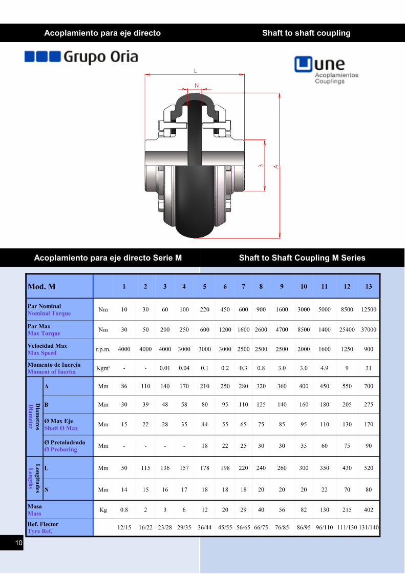
Acoplamiento para eje directo Shaft to shaft coupling
Acoplamiento para eje directo Serie M Shaft to Shaft Coupling M Series
Mod. M 1 2 3 4 5 6 7 8 9 10 11 12 13
Par Nominal
Nominal Torque Nm 10 30 60 100 220 450 600 900 1600 3000 5000 8500 12500
Par Max
Max Torque Nm 30 50 200 250 600 1200 1600 2600 4700 8500 1400 25400 37000
Velocidad Max
Max Speed r.p.m. 4000 4000 4000 3000 3000 3000 2500 2500 2500 2000 1600 1250 900
Momento de Inercia
Moment of Inertia Kgm² - - 0.01 0.04 0.1 0.2 0.3 0.8 3.0 3.0 4.9 9 31
Dia
metro
s
Dia
meter
A Mm 86 110 140 170 210 250 280 320 360 400 450 550 700
B Mm 30 39 48 58 80 95 110 125 140 160 180 205 275
Ø Max Eje
Shaft Ø Max Mm 15 22 28 35 44 55 65 75 85 95 110 130 170
Ø Pretaladrado
Ø Preboring Mm - - - - 18 22 25 30 30 35 60 75 90
Lon
gitu
des
Len
gth
s
L Mm 50 115 136 157 178 198 220 240 260 300 350 430 520
N Mm 14 15 16 17 18 18 18 20 20 20 22 70 80
Masa
Mass Kg 0.8 2 3 6 12 20 29 40 56 82 130 215 402
12/15 16/22 23/28 29/35 36/44 45/55 56/65 66/75 76/85 86/95 96/110 111/130 131/140 Ref. Flector
Tyre Ref.
10
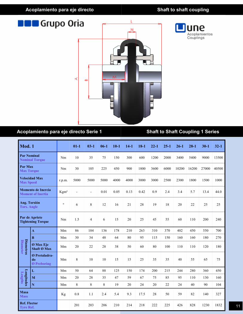
Mod. 1 01-1 03-1 06-1 10-1 14-1 18-1 22-1 25-1 26-1 28-1 30-1 32-1
Par Nominal
Nominal Torque Nm 10 35 75 150 300 600 1200 2000 3400 5400 9000 13500
Par Max
Max Torque Nm 30 105 225 450 900 1800 3600 6000 10200 16200 27000 40500
Velocidad Max
Max Speed r.p.m. 5000 5000 5000 4000 4000 3000 3000 2500 2300 1800 1500 1000
Momento de Inercia
Moment of Inertia Kgm² - - 0.01 0.05 0.13 0.42 0.9 2.4 3.4 5.7 13.4 44.0
Ang. Torsión
Tors. Angle º 6 8 12 16 21 28 19
18
20 22 25 25
Par de Apriete
Tightening Torque Nm 1.5 4 6 15 20 25 45 55 60 110 200
240
Dia
metro
s
Dia
meter
A Mm 86 104 136 178 210 263 310 370 402 450 550 700
B Mm 30 34 48 64 80 95 115 150 160 160 180 270
Ø Max Eje
Shaft Ø Max Mm 20 22 28 38 50 60 80 100 110 110 120 180
Ø Pretaladra-
do
Ø Preboring
Mm 8 10 10 15 15 25 35 35 40 55 65 75
Lon
gitu
des
Len
gth
s
L Mm 50 64 88 125 150 174 200 215 244 280 360 450
M Mm 20 28 35 47 59 67 75 85 95 110 130 160
N Mm 8 8 8 19 20 24 20 22 24 40 90 104
Masa
Mass Kg 0.8 1.1 2.4 5.4 9.3 17.5 28 50 59 82 140 327
201 203 206 210 214 218 222 225 426 828 1230 1832 Ref. Flector
Tyre Ref.
Acoplamiento para eje directo Shaft to shaft coupling
Acoplamiento para eje directo Serie 1 Shaft to Shaft Coupling 1 Series
11
Acoplamiento para eje directo Shaft to shaft coupling
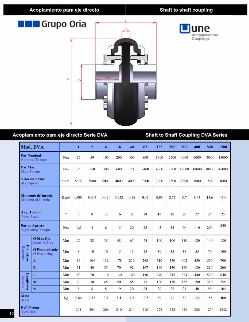
Acoplamiento para eje directo Serie DVA Shaft to Shaft Coupling DVA Series
Mod. DVA 1 2 6 16 40 63 125 200 300 400 800 1500
Par Nominal
Nominal Torque Nm 25 50 100 200 400 800 1600 2500 4000 6000 10000 15000
Par Max
Max Torque Nm 75 150 300 600 1200 2400 4800 7500 12000 18000 30000 45000
Velocidad Max
Max Speed r.p.m. 5000 5000 5000 4000 4000 3000 3000 2500 2300 1800 1500 1000
Momento de Inercia
Moment of Inertia Kgm² 0.001 0.004 0.011 0.052 0.14 0.42 0.96 2.73 3.7 6.45 14.6 46.0
Ang. Torsión
Tors. Angle º 6 8 12 16 21 28 19 18 20 22 25 25
Par de Apriete
Tightening Torque Nm 1.5 4 6 15 20 25 45 55 60 110 200
240
Dia
metro
s
Dia
meter
Ø Max Eje
Shaft Ø Max Mm 22 28 38 48 65 75 100 100 110 120 140 180
Ø Pretaladrado
Ø Preboring Mm 8 10 10 15 15 25 30 35 38 55 70 100
A Mm 86 104 136 178 210 263 310 370 402 450 550 700
B Mm 31 40 55 70 92 107 140 150 160 180 210 260
Lon
gitu
des
Len
gth
s
L Mm 60 70 110 130 160 190 240 345 364 440 520 640
M Mm 26 30 45 50 65 75 100 150 155 190 210 255
N Mm 8 8 8 19 20 24 20 22 24 40 90 104
Masa
Mass Kg 0.84 1.15 2.5 5.4 9.5 17.5 30 71 82 122 185 400
201 203 206 210 214 218 222 225 426 828 1230 1832 Ref. Flector
Tyre Ref. 12
Acoplamiento para eje directo Shaft to shaft coupling
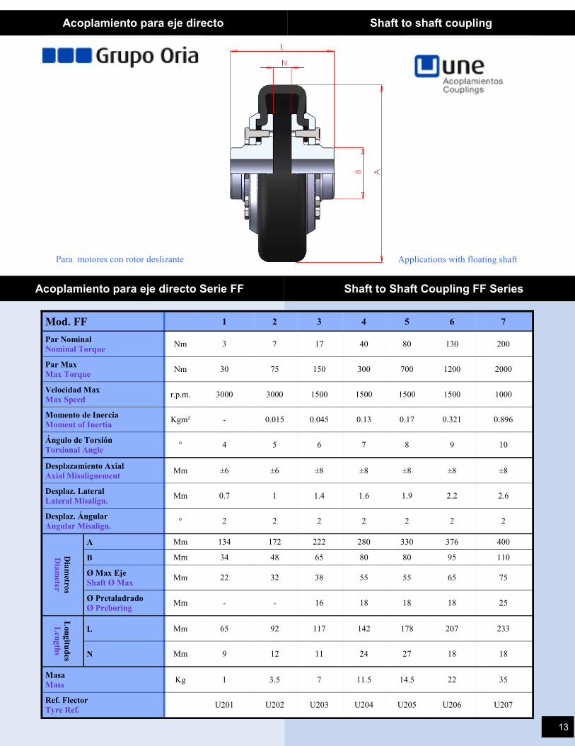
Acoplamiento para eje directo Serie FF Shaft to Shaft Coupling FF Series
Mod. FF 1 2 3 4 5 6 7
Par Nominal
Nominal Torque Nm 3 7 17 40 80 130 200
Par Max
Max Torque Nm 30 75 150 300 700 1200 2000
Velocidad Max
Max Speed r.p.m. 3000 3000 1500 1500 1500 1500 1000
Momento de Inercia
Moment of Inertia Kgm² - 0.015 0.045 0.13 0.17 0.321 0.896
Ángulo de Torsión
Torsional Angle ° 4 5 6 7 8 9 10
Desplazamiento Axial
Axial Misalignement Mm ±6 ±6 ±8 ±8 ±8 ±8 ±8
Desplaz. Lateral
Lateral Misalign. Mm 0.7 1 1.4 1.6 1.9 2.2 2.6
Desplaz. Ángular
Angular Misalign. ° 2 2 2 2 2 2 2
Dia
metro
s
Dia
meter
A Mm 134 172 222 280 330 376 400
B Mm 34 48 65 80 80 95 110
Ø Max Eje
Shaft Ø Max Mm 22 32 38 55 55 65 75
Ø Pretaladrado
Ø Preboring Mm - - 16 18 18 18 25
Lon
gitu
des
Len
gth
s
L Mm 65 92 117 142 178 207 233
N Mm 9 12 11 24 27 18 18
Masa
Mass Kg 1 3.5 7 11.5 14.5 22 35
U201 U202 U203 U204 U205 U206 U207 Ref. Flector
Tyre Ref.
Para motores con rotor deslizante Applications with floating shaft
13
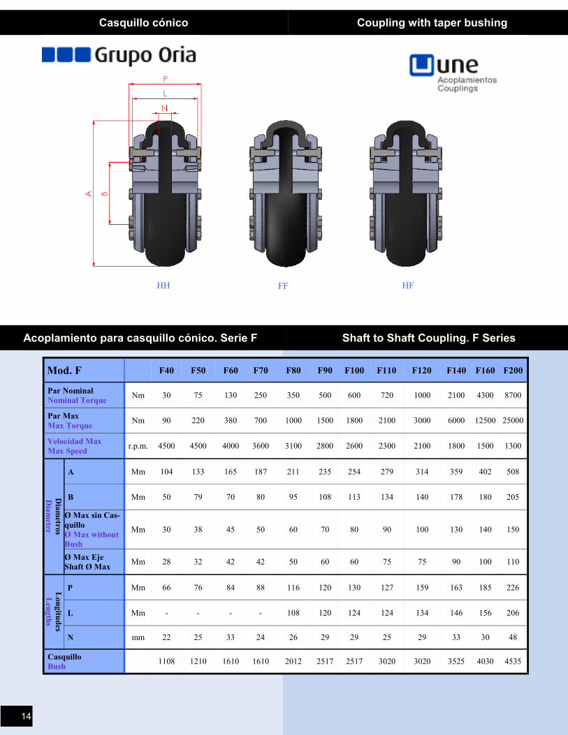
Casquillo cónico Coupling with taper bushing
Acoplamiento para casquillo cónico. Serie F Shaft to Shaft Coupling. F Series
Mod. F F40 F50 F60 F70 F80 F90 F100 F110 F120 F140 F160 F200
Par Nominal
Nominal Torque Nm 30 75 130 250 350 500 600 720 1000 2100 4300 8700
Par Max
Max Torque Nm 90 220 380 700 1000 1500 1800 2100 3000 6000 12500 25000
Velocidad Max
Max Speed r.p.m. 4500 4500 4000 3600 3100 2800 2600 2300 2100 1800 1500 1300
Dia
metro
s
Dia
meter
A Mm 104 133 165 187 211 235 254 279 314 359 402 508
B Mm 50 79 70 80 95 108 113 134 140 178 180 205
Ø Max sin Cas-
quillo
Ø Max without
Bush
Mm 30 38 45 50 60 70 80 90 100 130 140 150
Ø Max Eje
Shaft Ø Max Mm 28 32 42 42 50 60 60 75 75 90 100 110
Lon
gitu
des
Len
gth
s
P Mm 66 76 84 88 116 120 130 127 159 163 185 226
L Mm - - - - 108 120 124 124 134 146 156 206
N mm 22 25 33 24 26 29 29 25 29 33 30 48
Casquillo
Bush 1108 1210 1610 1610 2012 2517 2517 3020 3020 3525 4030 4535
HH FF HF
14
HF FF HH
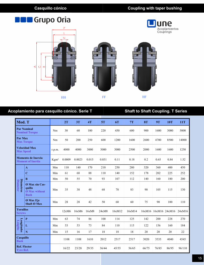
Casquillo cónico Coupling with taper bushing
Acoplamiento para casquillo cónico. Serie T Shaft to Shaft Coupling. T Series
Mod. T 2T 3T 4T 5T 6T 7T 8T 9T 10T 11T
Par Nominal
Nominal Torque Nm 30 60 100 220 450 600 900 1600 3000 5000
Par Max
Max Torque Nm 50 200 250 600 1200 1600 2600 4700 8500 14000
Velocidad Max
Max Speed r.p.m. 4000 4000 3000 3000 3000 2500 2000 1600 1600 1250
Momento de Inercia
Moment of Inertia Kgm² 0.0009 0.0023 0.015 0.031 0.11 0.18 0.2 0.65 0.84 1.52
Dia
metro
s
Dia
meter
A Mm 110 140 170 210 250 280 320 360 400 450
C Mm 61 68 88 110 140 152 178 202 225 252
B Mm 50 55 70 93 107 112 140 160 180 200
Ø Max sin Cas-
quillo
Ø Max without
Bush
Mm 35 38 48 68 78 83 90 105 115 130
Ø Max Eje
Shaft Ø Max Mm 28 28 42 50 60 60 75 90 100 110
Tornillos
Screws 12xM6 16xM6 16xM8 24xM8 16xM12 16xM14 16xM16 16xM16 24xM16 24xM16
Lon
gitu
des
Len
gth
s
P Mm 63 74 86 100 114 125 142 200 228 270
L Mm 53 53 73 84 110 115 122 156 160 184
N Mm 15 16 17 18 18 18 20 20 20 22
Casquillo
Bush 1108 1108 1610 2012 2517 2517 3020 3535 4040 4545
16/22 23/28 29/35 36/44 45/55 56/65 66/75 76/85 86/95 96/110 Ref. Flector
Tyre Ref.
15
Casquillo cónico Coupling with taper bushing
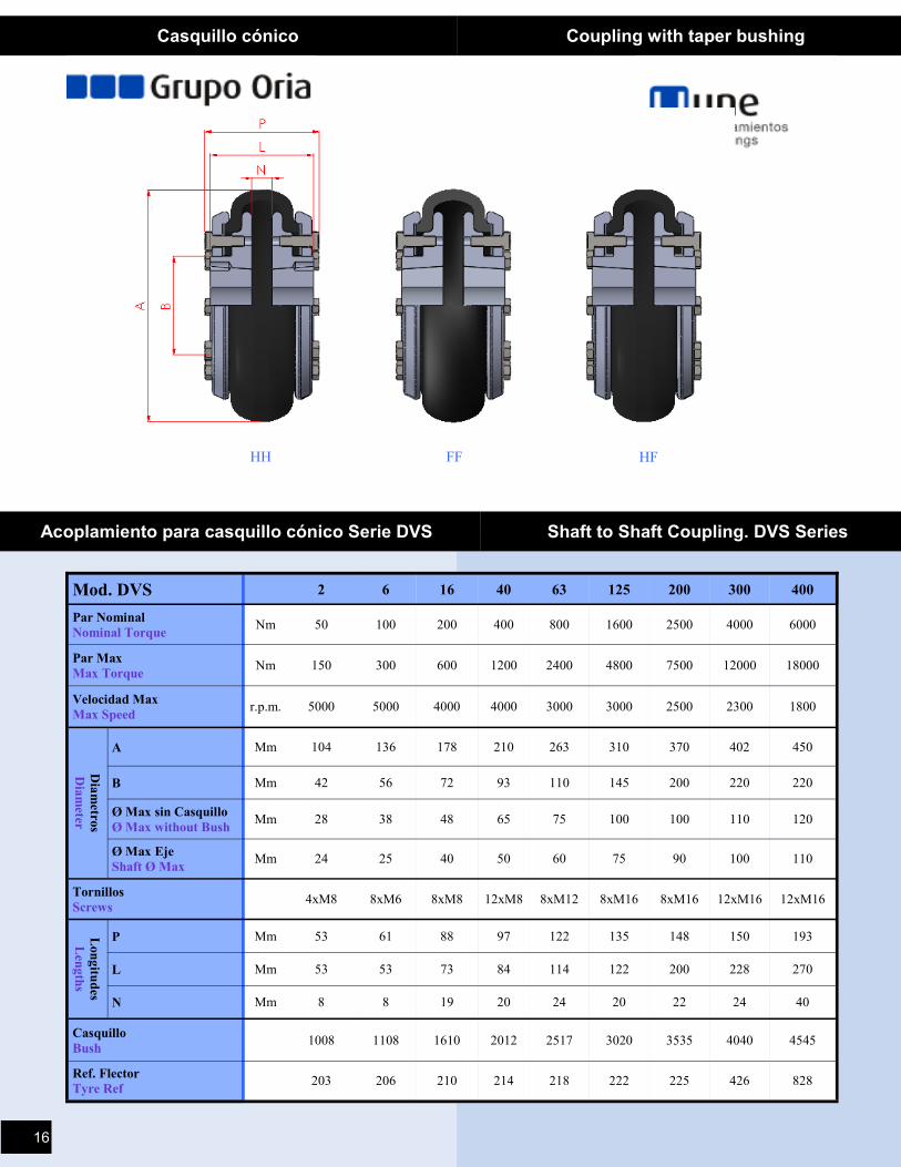
Acoplamiento para casquillo cónico Serie DVS Shaft to Shaft Coupling. DVS Series
Mod. DVS 2 6 16 40 63 125 200 300 400
Par Nominal
Nominal Torque Nm 50 100 200 400 800 1600 2500 4000 6000
Par Max
Max Torque Nm 150 300 600 1200 2400 4800 7500 12000 18000
Velocidad Max
Max Speed r.p.m. 5000 5000 4000 4000 3000 3000 2500 2300 1800
Dia
metro
s
Dia
meter
A Mm 104 136 178 210 263 310 370 402 450
B Mm 42 56 72 93 110 145 200 220 220
Ø Max sin Casquillo
Ø Max without Bush Mm 28 38 48 65 75 100 100 110 120
Ø Max Eje
Shaft Ø Max Mm 24 25 40 50 60 75 90 100 110
Tornillos
Screws 4xM8 8xM6 8xM8 12xM8 8xM12 8xM16 8xM16 12xM16 12xM16
P Mm 53 61 88 97 122 135 148 150 193 Lon
gitu
des
Len
gth
s
L Mm 53 53 73 84 114 122 200 228 270
N Mm 8 8 19 20 24 20 22 24 40
Casquillo
Bush 1008 1108 1610 2012 2517 3020 3535 4040 4545
Ref. Flector
Tyre Ref 203 206 210 214 218 222 225 426 828
HH FF HF
16
13
Tipo / type A Tipo / type B
h(*)b
Tm
ax
0D
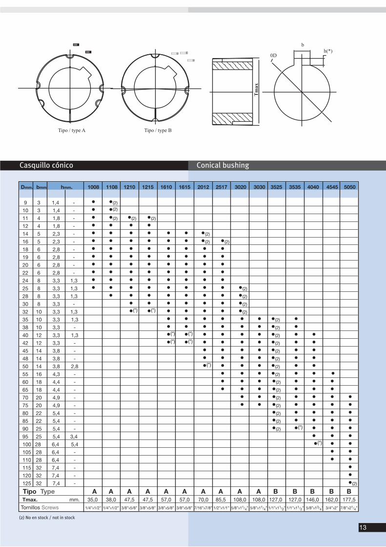
Casquillo cónico Conical bushing
Dmm. bmm hmm. 1008 1108 1210 1215 1610 1615 2012 2517 3020 3030 3525 3535 4040 4545 5050
9 3 1,4 - (2) . . . . . . . . . . . . .
10 3 1,4 - (2) . . . . . . . . . . . . .
11 4 1,8 - (2) (2) (2) . . . . . . . . . . .
12 4 1,8 - . . . . . . . . . . .
14 5 2,3 - (2) . . . . . . . .
16 5 2,3 - (2) (2) . . . . . . .
18 6 2,8 - . . . . . . .
19 6 2,8 - . . . . . . .
20 6 2,8 - . . . . . . .
22 6 2,8 - . . . . . . .
24 8 3,3 1,3 . . . . . . .
25 8 3,3 1,3 (2) . . . . . .
28 8 3,3 1,3 . (2) . . . . . .
30 8 3,3 - . . (2) . . . . . .
32 10 3,3 1,3 . . (*) (*) (2) . . . . . .
35 10 3,3 1,3 . . . . (2) . . .
38 10 3,3 - . . . . (2) . . ..
40 12 3,3 1,3 . . . . (*) (*) (2) . .
42 12 3,3 - . . . . (*) (*) (2) . .
45 14 3,8 - . . . . . . (2) . ..
48 14 3,8 - . . . . . . (2) . .
50 14 3,8 2,8 . . . . . . (*) (2) . ..
55 16 4,3 - . . . . . . . (2) .
60 18 4,4 - . . . . . . . (2) .
65 18 4,4 - . . . . . . . (2) .
70 20 4,9 - . . . . . . . . (2)
75 20 4,9 - . . . . . . . . (2)
80 22 5,4 - . . . . . . . . . . (2)
85 22 5,4 - . . . . . . . . . . (2)
90 25 5,4 - . . . . . . . . . . (2) (*)
95 25 5,4 3,4 . . . . . . . . . .. .. .
100 28 6,4 5,4 . . . . . . . . . . . . (*)
105 28 6,4 - . . . . . . . . . . . . .
110 28 6,4 - . . . . . . . . . . . . ...
115 32 7,4 - . . . . . . . .. . .. ... . . .
120 32 7,4 - . . . . . . . .. . . . . . .
125 32 7,4 - .. . . . . . . . . . . . . . (2)
Tipo Type . . . A A A A A A A A A A B B B B BTmax. . .mm. 35,0 38,0 47,5 47,5 57,0 57,0 70,0 85,5 108,0 108,0 127,0 127,0 146,0 162,0 177,5
Tornillos Screws . . .1/4’’X1/2’’ 1/4’’X1/2’’ 3/8’’X5/8’’ 3/8’’X5/8’’ 3/8’’X5/8’’ 3/8’’X5/8’’ 7/16’’X7/8’’ 1/2’’X1/1’’ 5/8’’X11/4’’ 5/8’’X11/4’’ 1/1’’X11/2’’ 1/1’’X11/2’’ 5/8’’X13/4’’ 3/4’’X2’’ 7/8’’X21/4’’
(2) No en stock / not in stock
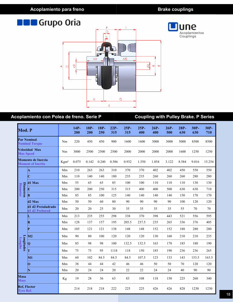
Acoplamiento para freno Brake couplings
Acoplamiento con Polea de freno. Serie P Coupling with Pulley Brake. P Series
Mod. P 14P-
200
18P-
200
18P-
250
22P-
315
25P-
315
25P-
400
26P-
400
26P-
500
28P-
630
30P-
630
30P-
710
Par Nominal
Nominal Torque Nm 220 450 450 900 1600 1600 3000 3000 5000 8500 8500
Velocidad Max
Max Speed Nm 3000 2500 2500 2500 2000 2000 2000 2000 1600 1250 1250
Momento de Inercia
Moment of Inertia Kgm² 0.075 0.142 0.240 0.586 0.932 1.550 1.854 3.122 8.584 9.016 15.254
Dia
metro
s
Dia
meter
A Mm 210 263 263 310 370 370 402 402 450 550 550
C Mm 110 140 140 180 235 235 260 260 260 280 280
d1 Max Mm 55 65 65 85 100 100 110 110 110 130 130
E Mm 200 200 250 315 315 400 400 500 630 630 710
B Mm 85 85 100 125 140 140 140 140 150 170 170
d2 Max Mm 50 50 60 80 90 90 90 90 100 120 120
d1 d2 Pretaladrado
d1 d2 Prebored Mm 20 20 25 30 35 35 35 35 55 70 70
Lon
gitu
des
Len
gth
s L Mm 213 235 255 298 338 370 398 443 521 556 595
R Mm 128 137 157 195 205.5 237.5 235 265 336 376 405
P Mm 105 121 121 138 148 148 152 152 188 280 280
M2 Mm 90 80 100 120 120 120 130 160 210 210 235
Q Mm 85 98 98 100 132.5 132.5 163 178 185 180 190
T Mm 75 75 95 1118 118 150 185 190 236 236 265
M1 Mm 60 102 84.5 84.5 84.5 107.5 123 133 143 153.5 163.5
O Mm 38 44 44 42 46 46 50 50 70 120 120
N Mm 20 24 24 20 22 22 24 24 40 90 90
Masa
Mass Kg 19 28 36 63 83 108 118 150 225 260 340
214 218 218 222 225 225 426 426 828 1230 1230 Ref, Flector
Tyre Ref.
18
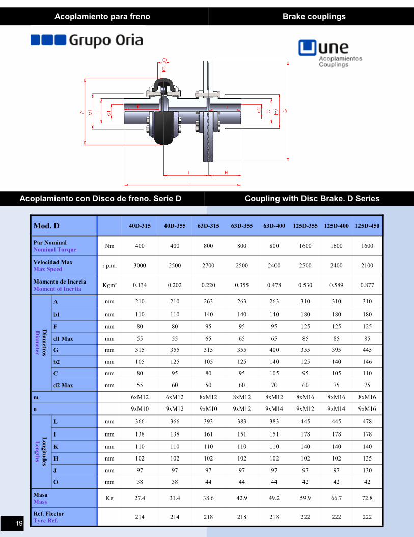
Acoplamiento para freno Brake couplings
Acoplamiento con Disco de freno. Serie D Coupling with Disc Brake. D Series
Mod. D 40D-315 40D-355 63D-315 63D-355 63D-400 125D-355 125D-400 125D-450
Par Nominal
Nominal Torque Nm 400 400 800 800 800 1600 1600 1600
Velocidad Max
Max Speed r.p.m. 3000 2500 2700 2500 2400 2500 2400 2100
Momento de Inercia
Moment of Inertia Kgm² 0.134 0.202 0.220 0.355 0.478 0.530 0.589 0.877
Dia
metro
s
Dia
meter
A mm 210 210 263 263 263 310 310 310
b1 mm 110 110 140 140 140 180 180 180
F mm 80 80 95 95 95 125 125 125
d1 Max mm 55 55 65 65 65 85 85 85
G mm 315 355 315 355 400 355 395 445
b2 mm 105 125 105 125 140 125 140 146
C mm 80 95 80 95 105 95 105 110
d2 Max mm 55 60 50 60 70 60 75 75
m 6xM12 6xM12 8xM12 8xM12 8xM12 8xM16 8xM16 8xM16
n 9xM10 9xM12 9xM10 9xM12 9xM14 9xM12 9xM14 9xM16
Lon
gitu
des
Len
gth
s
L mm 366 366 393 383 383 445 445 478
I mm 138 138 161 151 151 178 178 178
K mm 110 110 110 110 110 140 140 140
H mm 102 102 102 102 102 102 102 135
J mm 97 97 97 97 97 97 97 130
O mm 38 38 44 44 44 42 42 42
Masa
Mass Kg 27.4 31.4 38.6 42.9 49.2 59.9 66.7 72.8
214 214 218 218 218 222 222 222 Ref. Flector
Tyre Ref. 19
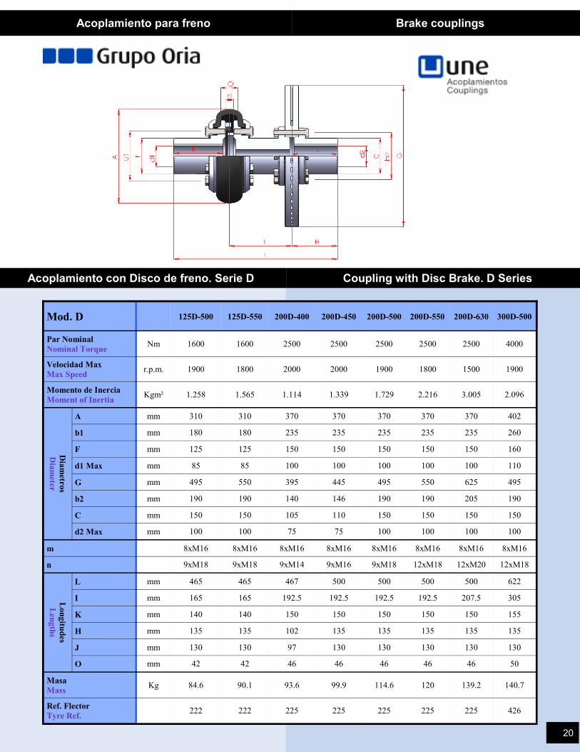
Mod. D 125D-500 125D-550 200D-400 200D-450 200D-500 200D-550 200D-630 300D-500
Par Nominal
Nominal Torque Nm 1600 1600 2500 2500 2500 2500 2500 4000
Velocidad Max
Max Speed r.p.m. 1900 1800 2000 2000 1900 1800 1500 1900
Momento de Inercia
Moment of Inertia Kgm² 1.258 1.565 1.114 1.339 1.729 2.216 3.005 2.096
Dia
metro
s
Dia
meter
A mm 310 310 370 370 370 370 370 402
b1 mm 180 180 235 235 235 235 235 260
F mm 125 125 150 150 150 150 150 160
d1 Max mm 85 85 100 100 100 100 100 110
G mm 495 550 395 445 495 550 625 495
b2 mm 190 190 140 146 190 190 205 190
C mm 150 150 105 110 150 150 150 150
d2 Max mm 100 100 75 75 100 100 100 100
m 8xM16 8xM16 8xM16 8xM16 8xM16 8xM16 8xM16 8xM16
n 9xM18 9xM18 9xM14 9xM16 9xM18 12xM18 12xM20 12xM18
Lon
gitu
des
Len
gth
s
L mm 465 465 467 500 500 500 500 622
I mm 165 165 192.5 192.5 192.5 192.5 207.5 305
K mm 140 140 150 150 150 150 150 155
H mm 135 135 102 135 135 135 135 135
J mm 130 130 97 130 130 130 130 130
O mm 42 42 46 46 46 46 46 50
Masa
Mass Kg 84.6 90.1 93.6 99.9 114.6 120 139.2 140.7
222 222 225 225 225 225 225 426 Ref. Flector
Tyre Ref.
Acoplamiento para freno Brake couplings
Acoplamiento con Disco de freno. Serie D Coupling with Disc Brake. D Series
20
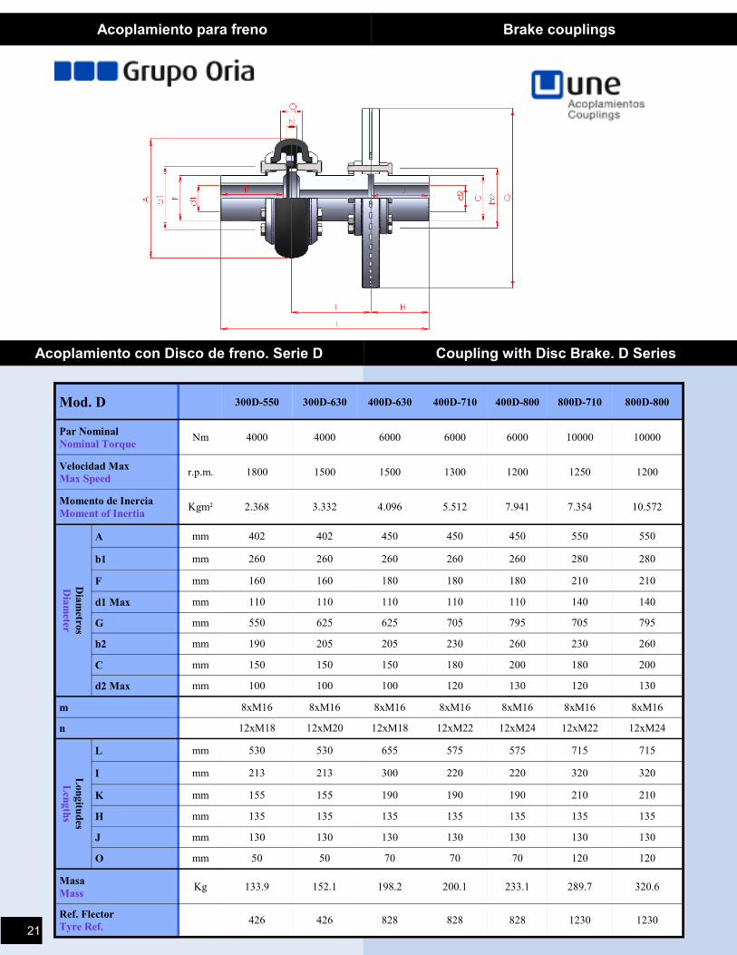
Mod. D 300D-550 300D-630 400D-630 400D-710 400D-800 800D-710 800D-800
Par Nominal
Nominal Torque Nm 4000 4000 6000 6000 6000 10000 10000
Velocidad Max
Max Speed r.p.m. 1800 1500 1500 1300 1200 1250 1200
Momento de Inercia
Moment of Inertia Kgm² 2.368 3.332 4.096 5.512 7.941 7.354 10.572
Dia
metro
s
Dia
meter
A mm 402 402 450 450 450 550 550
b1 mm 260 260 260 260 260 280 280
F mm 160 160 180 180 180 210 210
d1 Max mm 110 110 110 110 110 140 140
G mm 550 625 625 705 795 705 795
b2 mm 190 205 205 230 260 230 260
C mm 150 150 150 180 200 180 200
d2 Max mm 100 100 100 120 130 120 130
m 8xM16 8xM16 8xM16 8xM16 8xM16 8xM16 8xM16
n 12xM18 12xM20 12xM18 12xM22 12xM24 12xM22 12xM24
Lon
gitu
des
Len
gth
s
L mm 530 530 655 575 575 715 715
I mm 213 213 300 220 220 320 320
K mm 155 155 190 190 190 210 210
H mm 135 135 135 135 135 135 135
J mm 130 130 130 130 130 130 130
O mm 50 50 70 70 70 120 120
Masa
Mass Kg 133.9 152.1 198.2 200.1 233.1 289.7 320.6
Ref. Flector
Tyre Ref. 426 426 828 828 828 1230 1230
Acoplamiento para freno Brake couplings
Acoplamiento con Disco de freno. Serie D Coupling with Disc Brake. D Series
21
Acoplamiento con Espaciador Spacer Couplings
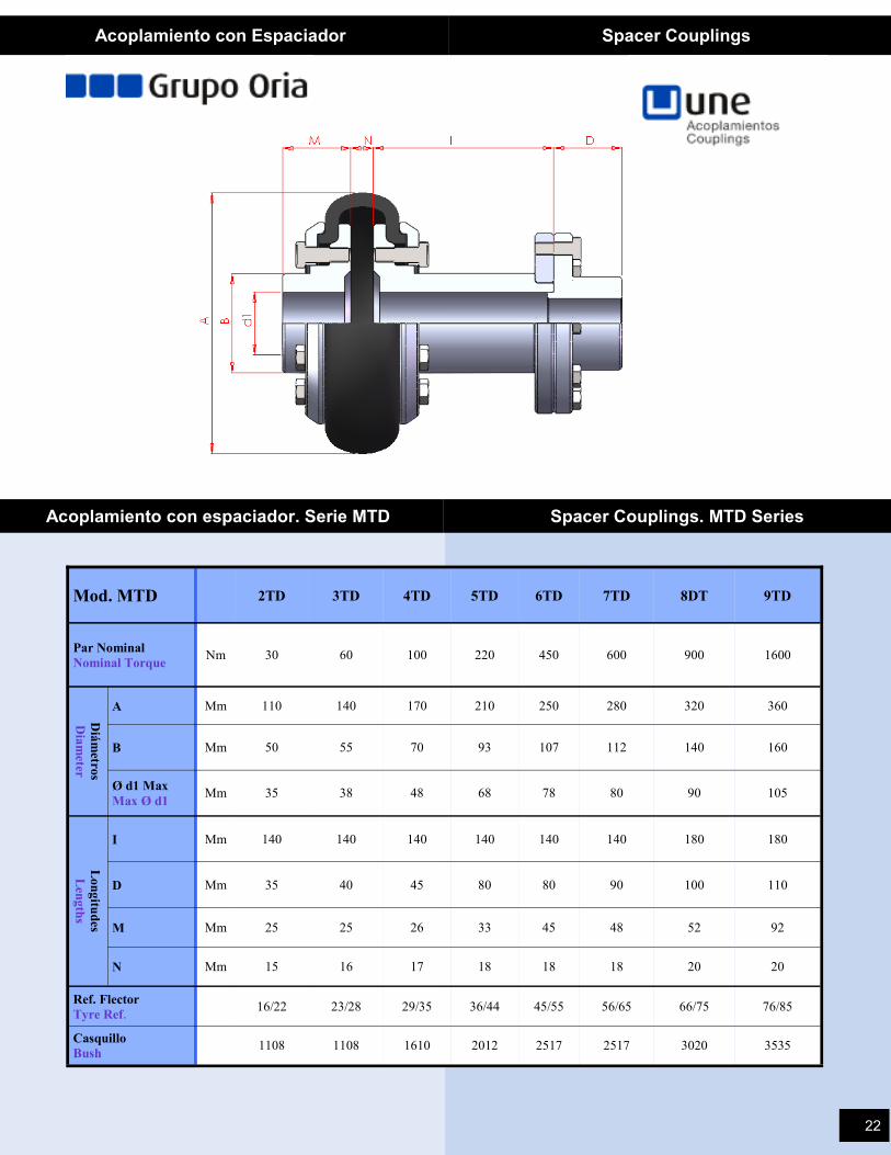
Acoplamiento con espaciador. Serie MTD Spacer Couplings. MTD Series
Mod. MTD 2TD 3TD 4TD 5TD 6TD 7TD 8DT 9TD
Par Nominal
Nominal Torque Nm 30 60 100 220 450 600 900 1600
Diá
metro
s
Dia
meter
A Mm 110 140 170 210 250 280 320 360
B Mm 50 55 70 93 107 112 140 160
Ø d1 Max
Max Ø d1 Mm 35 38 48 68 78 80 90 105
Lon
gitu
des
Len
gth
s
I Mm 140 140 140 140 140 140 180 180
D Mm 35 40 45 80 80 90 100 110
M Mm 25 25 26 33 45 48 52 92
N Mm 15 16 17 18 18 18 20 20
Ref. Flector
Tyre Ref. 16/22 23/28 29/35 36/44 45/55 56/65 66/75 76/85
1108 1108 1610 2012 2517 2517 3020 3535 Casquillo
Bush
22
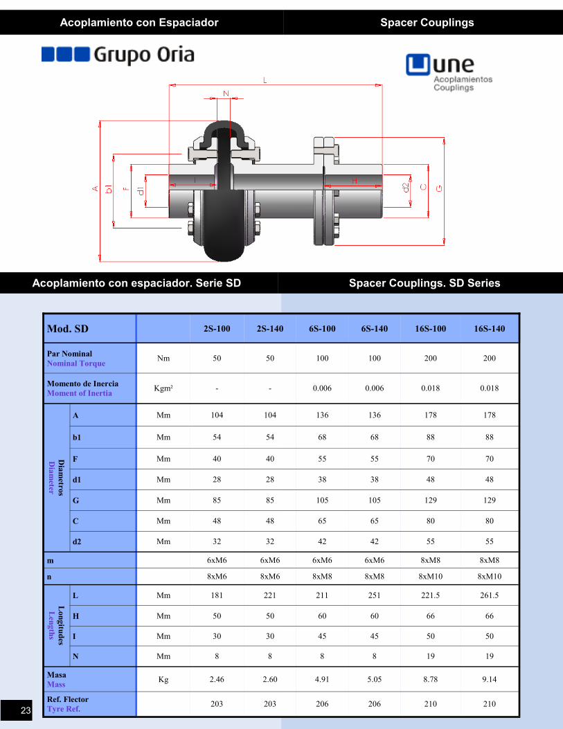
Acoplamiento con espaciador. Serie SD Spacer Couplings. SD Series
Mod. SD 2S-100 2S-140 6S-100 6S-140 16S-100 16S-140
Par Nominal
Nominal Torque Nm 50 50 100 100 200 200
Momento de Inercia
Moment of Inertia Kgm² - - 0.006 0.006 0.018 0.018
Dia
metro
s
Dia
meter
A Mm 104 104 136 136 178 178
b1 Mm 54 54 68 68 88 88
F Mm 40 40 55 55 70 70
d1 Mm 28 28 38 38 48 48
G Mm 85 85 105 105 129 129
C Mm 48 48 65 65 80 80
d2 Mm 32 32 42 42 55 55
m 6xM6 6xM6 6xM6 6xM6 8xM8 8xM8
n 8xM6 8xM6 8xM8 8xM8 8xM10 8xM10
Lon
gitu
des
Len
gth
s
L Mm 181 221 211 251 221.5 261.5
H Mm 50 50 60 60 66 66
I Mm 30 30 45 45 50 50
N Mm 8 8 8 8 19 19
Masa
Mass Kg 2.46 2.60 4.91 5.05 8.78 9.14
Ref. Flector
Tyre Ref. 203 203 206 206 210 210
Acoplamiento con Espaciador Spacer Couplings
23
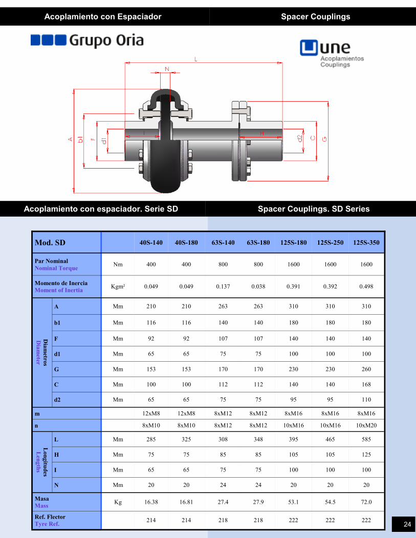
Mod. SD 40S-140 40S-180 63S-140 63S-180 125S-180 125S-250 125S-350
Par Nominal
Nominal Torque Nm 400 400 800 800 1600 1600 1600
Momento de Inercia
Moment of Inertia Kgm² 0.049 0.049 0.137 0.038 0.391 0.392 0.498
Dia
metro
s
Dia
meter
A Mm 210 210 263 263 310 310 310
b1 Mm 116 116 140 140 180 180 180
F Mm 92 92 107 107 140 140 140
d1 Mm 65 65 75 75 100 100 100
G Mm 153 153 170 170 230 230 260
C Mm 100 100 112 112 140 140 168
d2 Mm 65 65 75 75 95 95 110
m 12xM8 12xM8 8xM12 8xM12 8xM16 8xM16 8xM16
n 8xM10 8xM10 8xM12 8xM12 10xM16 10xM16 10xM20
Lon
gitu
des
Len
gth
s
L Mm 285 325 308 348 395 465 585
H Mm 75 75 85 85 105 105 125
I Mm 65 65 75 75 100 100 100
N Mm 20 20 24 24 20 20 20
Masa
Mass Kg 16.38 16.81 27.4 27.9 53.1 54.5 72.0
Ref. Flector
Tyre Ref. 214 214 218 218 222 222 222
Acoplamiento con Espaciador Spacer Couplings
Acoplamiento con espaciador. Serie SD Spacer Couplings. SD Series
24
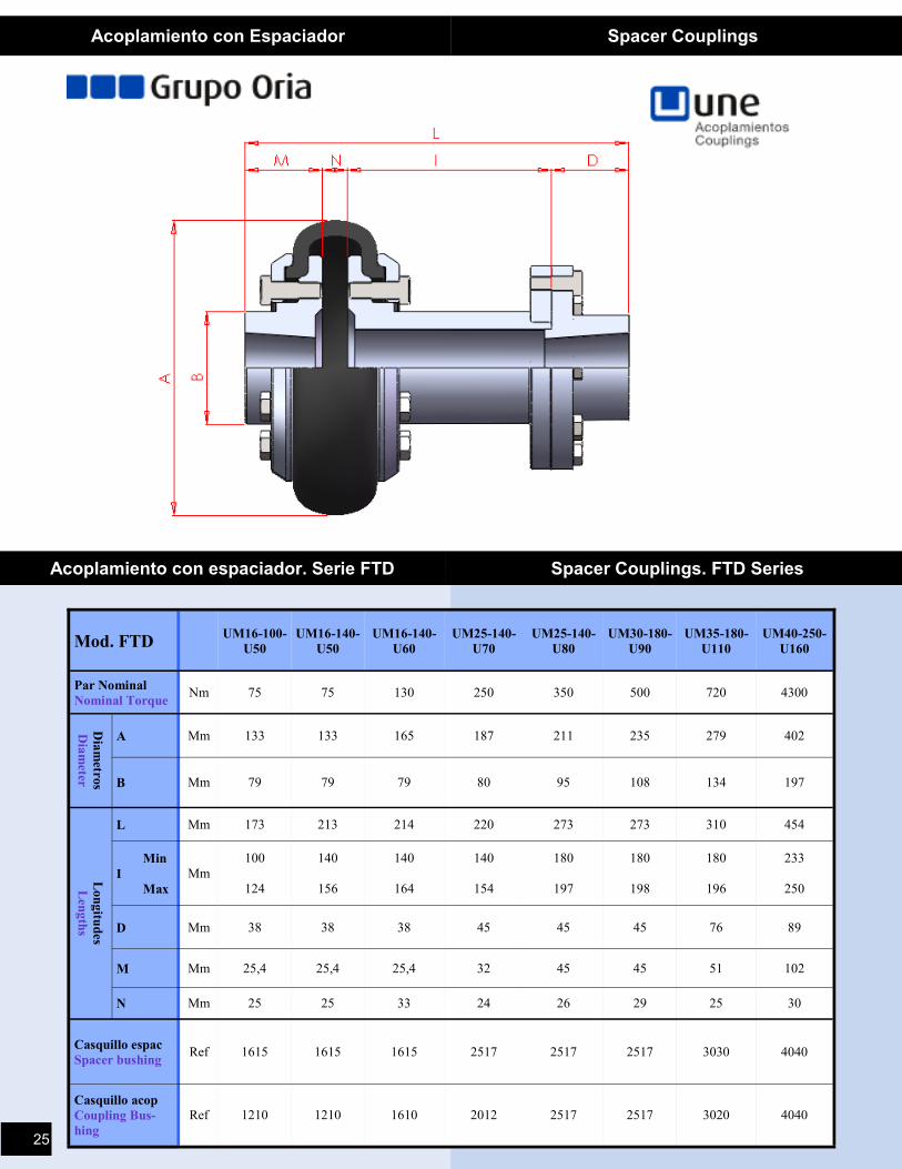
Acoplamiento con espaciador. Serie FTD Spacer Couplings. FTD Series
Mod. FTD UM16-100-
U50
UM16-140-
U50
UM16-140-
U60
UM25-140-
U70
UM25-140-
U80
UM30-180-
U90
UM35-180-
U110
UM40-250-
U160
Par Nominal
Nominal Torque Nm 75 75 130 250 350 500 720 4300
Dia
metro
s
Dia
meter
A Mm 133 133 165 187 211 235 279 402
B Mm 79 79 79 80 95 108 134 197
Lon
gitu
des
Len
gth
s L Mm 173 213 214 220 273 273 310 454
Min
I
Max
Mm
100
124
140
156
140
164
140
154
180
197
180
198
180
196
233
250
D Mm 38 38 38 45 45 45 76 89
M Mm 25,4 25,4 25,4 32 45 45 51 102
N Mm 25 25 33 24 26 29 25 30
Casquillo espac
Spacer bushing Ref 1615 1615 1615 2517 2517 2517 3030 4040
Ref 1210 1210 1610 2012 2517 2517 3020 4040 Casquillo acop
Coupling Bus-
hing
Acoplamiento con Espaciador Spacer Couplings
25