Embed Size (px)
Citation preview

CMP238 – Projeto e Teste de Sistemas VLSI
Testbench
Projeto
Prof. Fernanda Lima Kastensmidt
http://www.stefanvhdl.com
CMP238Projeto e Teste de Sistemas VLSI

CMP238 – Projeto e Teste de Sistemas VLSI
Generating Clock and Reset Stimulus• Practically every testbench needs a clock and a reset
signal. . . . signal clk: std_logic := '0'; signal rst: std_logic; beginrst <= '0', '1' after 10 ns,
'0' after 30 ns; clk <= not clk after 8 ns; . . . Note that the clk signal needs to be initialized in the
declaration, as the inverse of 'U' (=uninitialized) is also 'U'.

CMP238 – Projeto e Teste de Sistemas VLSI
File tb_clk_rst.vhd

CMP238 – Projeto e Teste de Sistemas VLSI
Verification
• A simple XOR build from AND and OR gates is used as an example.
• An extra term is added to deliberately introduce an error.
Correto:y <= (x1 and not x2) or (x2 and not x1)Errado:y <= (x1 and not x2) or (x2 and not x1) or (x1 and x2);

CMP238 – Projeto e Teste de Sistemas VLSI
Exemplotest_seq: processbeginx1 <= '0'; x2 <= '0'; wait for 10 ns;x1 <= '1'; x2 <= '0'; wait for 10 ns; x1 <= '0'; x2 <= '1'; wait for 10 ns; x1 <= '1'; x2 <= '1';wait for 10 ns; x1 <= 'X'; x2 <= 'X'; ... end process test_seq;
X1 X2 XOR Y0 0 0 00 1 1 11 0 1 11 1 0 1

CMP238 – Projeto e Teste de Sistemas VLSI
y <= (x1 and not x2) or (x2 and not x1) or (x1 and x2);
• This code can now be simulated and it's possible to identify thedesign error by observing the waveforms:

CMP238 – Projeto e Teste de Sistemas VLSI
Assert Statements• Instead of looking at waves, it is more efficient to build in
checks which automatically verify the result of a simulation.
• This can be accomplished with the use of assert statements.
• An assert statement verifies that a certain condition holds true.
• If the condition is violated it will generate the associated message and will attach the specified severity level to it.

CMP238 – Projeto e Teste de Sistemas VLSI
ASSERT Statement
• The ASSERT statement serves as an exception handling within a program and is most often used for test purposes. For this a condition is defined, which should be fulfilled in normal operation mode. If this is not the case a fault message may be generated.
• The syntax is: assertion_statement ::= [ label : ] assertion ;
assertion ::= ASSERT condition [ REPORT expression ][ SEVERITY expression ]; If the condition following ASSERT is evaluated to false, the default
message "Assertion violation" is printed. By means of the REPORT statement, a self defined fault message can
be printed by presenting a text, which must be a string. The expression following the SEVERITY statement must have the type
severity_level and defines the fault class. Four fault classes are defined in severity_level: note, warning, error and failure. If the SEVERITY statement in the ASSERT statement is omitted, error is by default classified.

CMP238 – Projeto e Teste de Sistemas VLSI
Standard format• A standard format for error messages will also help to
identify the location of a bug. • The standard adopted here uses the first letter to
indicate the severity (I=Information, W=Warning, E=Error, F=Failure) followed by "@" and the entity name of the unit which generated the message.
• The "E@" notation makes it very easy to grep long logfiles and identify problems.
• Knowing the entity which detected a bug will aid fixing it, too.

CMP238 – Projeto e Teste de Sistemas VLSI
Example.... wait for 10 ns; x1 <= '1';x2 <= '1'; assert y = (x1 xor x2)
report "E@TB: circuit failed" severity Error;
wait for 10 ns; ...
A simulator executing the code will produce output similar to this:
# ** Error: E@TB: circuit failed # Time: 40 ns Iteration: 0 Instance: /tb1

CMP238 – Projeto e Teste de Sistemas VLSI
Example: doing it in paralel
processbeginwait for 2ns;assert y=x1 xor x2report "E@TB: circuit
failed" severity Error;
end process;
test_seq: processbeginx1 <= '0'; x2 <= '0'; wait for 10 ns;x1 <= '1'; x2 <= '0'; wait for 10 ns; x1 <= '0'; x2 <= '1'; wait for 10 ns; x1 <= '1'; x2 <= '1';wait for 10 ns; x1 <= 'X'; x2 <= 'X'; ... end process test_seq;

CMP238 – Projeto e Teste de Sistemas VLSI
Assert Package• Ideally the assert statement should provide information
about the condition in which the error occurred. • This will aid debugging substantially. • Below are two alternatives to the previous assert
statements. • One uses the 'image attribute from the VHDL 93
standard. • The other uses the conversion function str() from
package txt_util.vhd which is used extensively throughout this course.
• The package provides a somewhat less cumbersome way to handle string processing and similar tasks.
• Design under test (DUT): file tb1.vhd• Package: file txt_util.vhd
CMP238 – Projeto e Teste de Sistemas VLSI
assert y = (x1 xor x2) report "E@TB: failure at: x1="& std_logic'image(x1)& " x2="&
std_logic'image(x2) severity Error; OR
assert y = (x1 xor x2) report "E@TB: failure at: x1="& str(x1)& " x2="& str(x2) severityError;
• Shown below is the output of the two assert statements. It's nowmuch easier to identify the cause of the problem.
# ** Error: E@TB: failure at: x1='1' x2='1' # Time: 40 ns Iteration: 0 Instance: /tb1 # ** Error: E@TB: failure at: x1=1 x2=1 # Time: 40 ns Iteration: 0 Instance: /tb1
CMP238 – Projeto e Teste de Sistemas VLSI
Testbench Structure• The design and the test code must be located in
separately file. • Typical testbench code - such as text output and assert
statements - can not be synthesized and will at the very least create a number of unnecessary warnings from the tool.
• Also testbench code can have similar complexity as design code and if it's well structured, is quite likely to be reusable.

CMP238 – Projeto e Teste de Sistemas VLSI

CMP238 – Projeto e Teste de Sistemas VLSI
Writing to Files• Writing to files can be useful in a VHDL simulation. • Here is the header of an example program: library ieee; use ieee.std_logic_1164.all; use std.textio.all; use work.txt_util.all; entity FILE_LOG isgeneric ( log_file: string := "res.log" ); port( CLK : in std_logic; RST : in std_logic; x1 : in std_logic; x2 : in std_logic_vector(7 downto 0) ); end FILE_LOG;

CMP238 – Projeto e Teste de Sistemas VLSI
• For the purpose of this example two signals x1 and x2 shall be logged to a file on every rising clock edge.
• To operate on files they need to be declared: architecture log_to_file of FILE_LOG isfile l_file: TEXT open write_mode is log_file; begin• Here l_file is the file, it's of type TEXT and opened in write mode.
The log_file parameter is of type string and usually assigned with a generic as shown above.
• The following loop will log x1 and x2 into the file specified bylog_file:
while true loopwrite(l, str(x1)&" "& hstr(x2)& "h"); writeline(l_file, l); wait until CLK = '1';end loop; As can be seen VHDL writes to a file in two steps: first a string is
written to a variable of type line (that's what the write command does), then the line is appended to a file with the write line command.

CMP238 – Projeto e Teste de Sistemas VLSI
In the example shown here,• x1 is of type std_logic• x2 of type std_logic_vector. • The function str() will convert x1 in a string, the function
hstr() will convert x2 in a string in hex format. (Both functions are in txt_util.vhd).
• Strings and characters can be combined into a larger string with the & operator.
• The txt_util package provides a simpler way to write to a file, e.g. with:
print(l_file, str(x1)& " "& hstr(x2)& "h");

CMP238 – Projeto e Teste de Sistemas VLSI
• Which fits into a single line and doesn't require a line type variable. Also since the input to print is always a string no type casting is necessary.
• The usage can be illustrated by inserting the lines below in front of the while-loop. (The code will generate a header for the log file.)
print(l_file, "# x1 x2 "); print(l_file, "#----------"); print(l_file, " "); wait until RST='1'; wait until RST='0'; while true loop . . .

CMP238 – Projeto e Teste de Sistemas VLSI
Then the following will be the contents of res.log:# x1 x2 #----------0 01h 0 02h 0 03h ... 0 0Fh 1 10h 1 11h ...
If the waveforms shown below are applied to the entity:

CMP238 – Projeto e Teste de Sistemas VLSI
Files:
1) tb1.vhd (testbench + DUT)txt_util.vhd
2) txt_util.vhdfile_log.vhdstim_gen2.vhdtb_file_log.vhd
CMP238 – Projeto e Teste de Sistemas VLSI
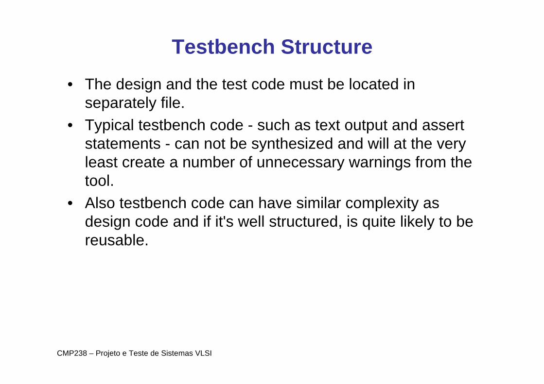
Reading from Files• Reading from files is very important for VHDL simulation.• Apart from using it in self-designed testbenches, many
commercially available testbench components make use of this method, too.
• Here is an example entity header:
entity FILE_READ isgeneric( stim_file: string :="sim.dat" ); port( CLK : in std_logic; RST : in std_logic; Y : out std_logic_vector(4 downto 0); EOG : out std_logic ); end FILE_READ;

CMP238 – Projeto e Teste de Sistemas VLSI
• In this example data is read from a file sim.dat at every rising clock edge and applied to the output vector Y.
• Once every line of the file is read the EOG (End Of Generation) flag is set.
• The declaration of the input file is shown below:
architecture read_from_file of FILE_READ isfile stimulus: TEXT open read_mode is stim_file; begin
CMP238 – Projeto e Teste de Sistemas VLSI
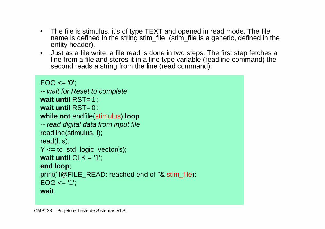
• The file is stimulus, it's of type TEXT and opened in read mode. The file name is defined in the string stim_file. (stim_file is a generic, defined in the entity header).
• Just as a file write, a file read is done in two steps. The first step fetches a line from a file and stores it in a line type variable (readline command) the second reads a string from the line (read command):
EOG <= '0'; -- wait for Reset to completewait until RST='1'; wait until RST='0'; while not endfile(stimulus) loop-- read digital data from input file readline(stimulus, l); read(l, s); Y <= to_std_logic_vector(s); wait until CLK = '1'; end loop; print("I@FILE_READ: reached end of "& stim_file); EOG <= '1';wait;
CMP238 – Projeto e Teste de Sistemas VLSI
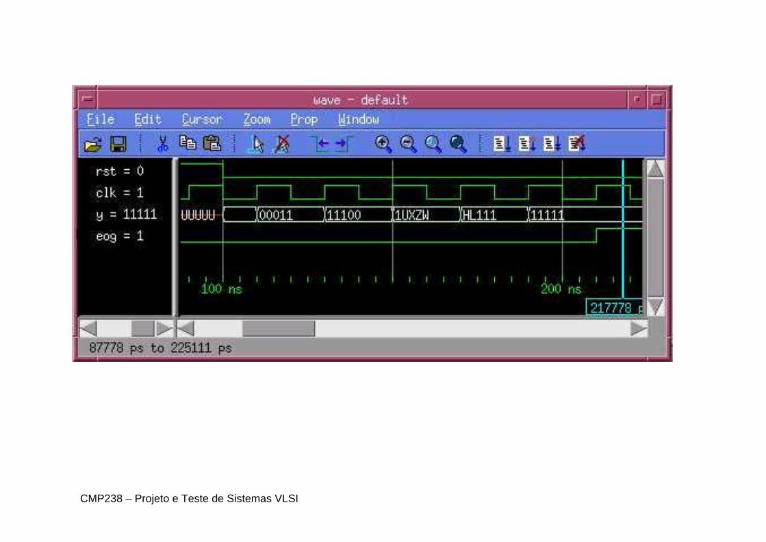
• Since a string is read from the input file, a conversion function is required to obtain a std_logic_vector.
• The function to_std_logic_vector(s) achieves that, it is part of the txt_util package.
• With the following contents of sim.dat: 00010 00011 11100 1UXZW HL111 11111 ...file_read.vhd will generate these waveforms:
CMP238 – Projeto e Teste de Sistemas VLSI

CMP238 – Projeto e Teste de Sistemas VLSI
Files3)• txt_util.vhd• file_read.vhd• tb_file_read.vhd• sim.dat (criar)

CMP238 – Projeto e Teste de Sistemas VLSI
• In addition to reading data, it's also possible to read commands from files.
• This will be discussed by extending the already introduced file_read.vhd.
• The new version will read hex data and will also understand a command: #count.
• Each time it is found in the input file the file reader shall count from 1 to 5 in binary format and present that count on the output port.
• Unfortunately the file I/O of VHDL is not very sophisticated.
• It's not allowed to read a string from a file where the string is longer than the number of characters in that line.

CMP238 – Projeto e Teste de Sistemas VLSI
• Here is what needs to be done in order to read variable lengthstrings from an input file:
readline(stimulus, l); s := (others => ‘0');for i in s'range loopread(l, c, in_string); s(i) := c; if not in_string then -- found end of line exit; end if; end loop; • The read function will return false for in_string once the last
character of the line has been read. The above function has beenplaced in txt_util.vhd and named str_read(stimulus, s).
• The length of s determines the maximum number of characters in aline which can be evaluated.

CMP238 – Projeto e Teste de Sistemas VLSI
• Using this function the following code will implement the set task: while not endfile(stimulus) loopstr_read(stimulus, s); if s(1 to 6) = "#count" then -- check for command "count"
for i in 1 to 5 loopY <= conv_std_logic_vector(i,5); wait until CLK = '1'; end loop;
else-- if it's not a command -> process data normally Y <= to_std_logic_vector(s(1 to 5)); wait until CLK = '1';
end if; end loop; print("I@FILE_READ: reached end of "& stim_file); EOG <= '1'; wait;
CMP238 – Projeto e Teste de Sistemas VLSI
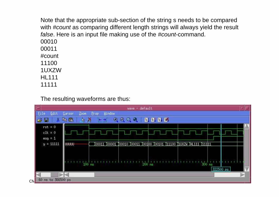
Note that the appropriate sub-section of the string s needs to be compared with #count as comparing different length strings will always yield the result false. Here is an input file making use of the #count-command. 00010 00011 #count 11100 1UXZW HL111 11111
The resulting waveforms are thus:

CMP238 – Projeto e Teste de Sistemas VLSI
Files
• txt_util.vhd• file_read2.vhd• sim2.dat (criar)• tb_file_read2.vhd

CMP238 – Projeto e Teste de Sistemas VLSI
The World of Perl• it's possible to read more from files than just data. • Many commercially available testbenches support
sophisticated commands. • There are limits however: in most cases structural
elements like loops and procedures are missing. • It's theoretically possible to extend the file reader into a
proper parser and add these language elements, however VHDL is not really suited for these tasks and access to the source code may not always be possible.
• A way to get around these problems is to generate the input files with a different language such as perl.

CMP238 – Projeto e Teste de Sistemas VLSI
• The perl script below will generate an input file which can be read by file_read.vhd.
print "00011\n"; print "11100\n"; for ($i=0;$i<10;$i++) {
print num2binary($i,5)."\n"; } print "1UXZW\n";print "11111\n";
File: tgen.pl

CMP238 – Projeto e Teste de Sistemas VLSI
Resulting Stimulus File
000111110000000000010001000011 00100 00101 00110 00111 01000 01001 01010 1UXZW HL111 11111
•It's straightforward to extend this approach e.g. for 256 iterations if all values of a 8 bit word are to be covered. •Entering these values manually would be very cumbersome. •The script actually calls a procedure num2binary which can be found in the complete script. •More complex procedures like Pseudo Random Bit Sequences (PRBS) patterns or CRC generators could be used in a similar fashion.

CMP238 – Projeto e Teste de Sistemas VLSI
Signal Monitors• Often it's desirable to monitor the status of a signal and
display messages whenever it changes. • A good example for this is an interrupt signal.• Here presented are two possibilities for implementing
this: -- report changes of the interrupt signalmonitor: process(INT_L) beginprint("I@TB: INT_L="& str(INT_L)); end process monitor; • The process will be executed each time there is an event
on INT_L. Whenever that happens a message will be printed.

CMP238 – Projeto e Teste de Sistemas VLSI
• Here is an alternative using an extensions of the print command which is available in txt_util.vhd:
-- report when interrupt is assertedprint(INT_L'event and INT_L = '0', "I@TB: INT_L="&
str(INT_L)); • This function has as a first parameter a boolean
expression and as the second parameter a message text.
• The message text will be printed whenever the booleanexpression is true.
• (In this case whenever INT_L changes to '0'). • The function does not need to be part of a process, it
can be used as a concurrent statement.
File simple_mon.vhd

CMP238 – Projeto e Teste de Sistemas VLSI
Projeto 1• Criar um testbench capaz de verificar funcionalmente o
comportamento de um contador up/down do tipo BCD.
1. Cada aluno irá descrever um contador up/down do tipoBCD em VHDL (nome_aluno_contador.vhd) e enviar o arquivo para o aluno a sua esquerda.
2. O aluno que receber o arquivo do colega devera criarum testbench para verifica-lo funcionalmente.
clkD (0 up, 1 down)reset
4 bits

CMP238 – Projeto e Teste de Sistemas VLSI
Dicas Projeto 11. Verificação 1: mandar contar para cima por 16 ciclos de
relogio e contar para baixo por 16 ciclos de relógio e avisar se o resultado alguma vez for maior que 9.
2. Verificação 2: quando contar para cima, o proximonumero tem que ser maior que o anterior.
3. Verificação 3: quando contar para baixo, o proximonumero tem que ser menor que o anterior.
4. Verificação 4: Ao fazer reset, a saida tem que ser zero.

CMP238 – Projeto e Teste de Sistemas VLSI
Projeto 2• Verificação funcional da seguinte máquina de estados já
codificada.
S0 S1
S3 S2
reset0X
10
1101
10
0X10
11
0X 11
10
11, 00
00 00
01 10
0001 0010
01001000
CodificaçãoOne-hot

CMP238 – Projeto e Teste de Sistemas VLSI
Dicas Projeto 2• Verificação 1: ver se todos os estados são atingidos em
algum momento ou seja, pelo menos uma vez o estadotem que ser 0001, 0010, 0100 e 1000. – Desafio: qual ordem de entradas? Há dois bits de
entradas que podem anteceder ou preceder qualqueroutro valor de entrada. (A=00, B=01, C=10, D=11)
ABCD, ACDB, ADCB, ADBC, BCDA, BDCA, BACD, BADC, CABD, CADC, CBDA, CBAD, DABC, DBCA, DCBA, DBAC, DCAB, … e isso é só quatro ciclos de relogio encadeado, o que acontece depois?
Vemos logo que não podemos fazer um teste exaustivo. Por isso os cores tem falhas!!! Impossivel verificarfuncionalmente tudo.