Embed Size (px)
Citation preview

ISTRUZIONI D’USO E DI INSTALLAZIONEINSTALLATION AND USER’S MANUALINSTRUCTIONS D’UTILISATION ET D’INSTALLATIONINSTALLATIONS-UND GEBRAUCHSANLEITUNGINSTRUCCIONES DE USO Y DE INSTALACIONINSTRUÇÕES DE USO E DE INSTALAÇÃO
D811494 ver. 05 02-07-07
I
GB
F
D
E
P
QUADRO COMANDO
CONTROL PANEL
CENTRALE DE COMMANDE
SELBSTÜBERWACHENDE STEUERUNG
CUADRO DE MANDOS
QUADRO DE COMANDO
LIBRA-C-MA
Via Lago di Vico, 4436015 Schio (VI)Tel.naz. 0445 696511Tel.int. +39 0445 696533Fax 0445 696522Internet: www.bft.itE-mail: [email protected]
8 027908 288554

INSTALLATION MANUALENGLISh
Thank you for buying this product, our company is sure that you will be more than satisfied with its performance.This product is supplied with an “Instruction Manual” which should be read carefully as it provides important information about safety, installation, op-eration and maintenance. This product complies with recognised technical standards and safety regula-tions. We declare that it is in conformity with the following European Directives: 89/336/EEC, 73/23/EEC, 98/37/EEC and subsequent amendments.
1) GENERAL SAFETYWARNING! An incorrect installation or improper use of the productcan cause damage to persons, animals or things.WARNING! Installation must be carried out using the safety devices and controls prescribed by the EN 12978 Standard.• The “Warnings” leaflet and “Instruction booklet” supplied with this
product should be read carefully as they provide important information about safety, installation, use and maintenance.
• Scrap packing materials (plastic, cardboard, polystyrene etc) according to the provisions set out by current standards. Keep nylon or polystyrene bags out of children’s reach.
• Keep the instructions together with the technical brochure for future reference.
• This product was exclusively designed and manufactured for the use specified in the present documentation. Any other use not specified in this documentation could damage the product and be dangerous.
• The Company declines all responsibility for any consequences result-ing from improper use of the product, or use which is different from that expected and specified in the present documentation.
• Do not install the product in explosive atmosphere.• The construction components of this product must comply with the following
European Directives: 89/336/CEE, 73/23/EEC, 98/37/EEC and subse-quent amendments. As for all non-EEC countries, the above-mentioned standards as well as the current national standards should be respected in order to achieve a good safety level.
• The Company declines all responsibility for any consequences resulting from failure to observe Good Technical Practice when constructing clos-ing structures (door, gates etc.), as well as from any deformation which might occur during use.
• The installation must comply with the provisions set out by the following European Directives: 89/336/CEE, 73/23/EEC, 98/37/EEC and subsequent amendments.
• Disconnect the electrical power supply before carrying out any work on the installation. Also disconnect any buffer batteries, if fitted.
• Fit an omnipolar or magnetothermal switch on the mains power supply, having a contact opening distance equal to or greater than 3,5 mm.
• Check that a differential switch with a 0.03A threshold is fitted just before the power supply mains.
• Check that earthing is carried out correctly: connect all metal parts for closure (doors, gates etc.) and all system components provided with an earth terminal.
• Fit all the safety devices (photocells, electric edges etc.) which are needed to protect the area from any danger caused by squashing, conveying and shearing.
• Position at least one luminous signal indication device (blinker) where it can be easily seen, and fix a Warning sign to the structure.
• The Company declines all responsibility with respect to the automation safety and correct operation when other manufacturers’ components are used.
• Only use original parts for any maintenance or repair operation.• Do not modify the automation components, unless explicitly authorised
by the company.• Instruct the product user about the control systems provided and the
manual opening operation in case of emergency.• Do not allow persons or children to remain in the automation opera-
tion area.• Keep radio control or other control devices out of children’s reach, in
order to avoid unintentional automation activation.• The user must avoid any attempt to carry out work or repair on the automa-
tion system, and always request the assistance of qualified personnel.• Anything which is not expressly provided for in the present instructions,
is not allowed.• Installation must be carried out using the safety devices and controls
prescribed by the EN 12978 Standard.
2) GENERAL OUTLINEThe LIBRA-C-MA control panel is supplied by the manufacturer with standard setting. Any alteration must be set by means of the incorporated display programmer or by means of universal palmtop programmer. The Control unit completely supports the EELINK protocol. Its main characteristics are: - Control of two low-voltage motors up to 40W power- Electronic torque setting with obstacle detection
- Limit-switch control inputs- Separate inputs for safety devices- Incorporated rolling-code radio receiver with transmitter cloningThe board is provided with a terminal board which can be pulled out for easier maintenance or replacement. The board is supplied with a series of pre-wired jumpers to facilitate the installer’s work.The jumpers relate to the following terminals: 15-17,15-18, 23-24, 23-25,, 23-24, 23-25, 23-26 and 23-27. If the above-mentioned terminals are in use, remove their. If the above-mentioned terminals are in use, remove their respective jumpers.
ChECKThe LIBRA-C-MA panel carries out a control (check) on the starting relays and safety devices (photocells) before carrying out each opening and closing cycle.In case of malfunction, check the devices connected for regular operation and check the wiring.
3) TEChNICAL DATAPower supply: ..............................................................230V~ ±10% 50Hz*Mains/low voltage insulation: .........................................> 2MOhm 500VWorking temperature: ............................................................. -10 to +55°CDielectric strength:…. .................. mains/low voltage 3750V~ per 1 minuteMotor output current: ...................................................................................with limit switches connected to terminals 5 and 8: .............3.5A+3.5A maxwith limit switches connected to terminals 24, 25, 26 and 27:...7.5A+7.5A max Motor relay commutation current: ......................................................... 10AMaximum motor power: ...........................................180W + 180W (24V )Supply to accessories: ............................... 24V~ (180mA max absorption)
24V~ V safe (180mA max absorption)Gate-open warning light:................................ N.O. contact (24V~/1A max) Blinker: ............................................................................... 24V~ 25W maxDimensions: ..............................................................................see figure 1Fuses: .......................................................................................see figure 2(* other voltages available on request) BATTERY KIT BT BAT (Fig.6)Charging voltage: ............................................................................27.2VCharging current: .............................................................................. 130mAOutside temperature when values were measured: ............................ 25°CBattery capacity: .................................................................. 2x (12V 1.2Ah)Flat battery protection threshold: ....................................................20.4VBattery charging time: ................................................................... 12/14 hrsNOTE: In case of operation with battery back up, the outputs to terminals 11-12 (24 V~) and 13-14 ( Vsafe 24 V~) have a voltage of 24 V , polarised as shown in Fig. 6. When installing the BT-BAT kit, check for correct connection of the safety devices. When using the BT BAT battery kit, the value of the power supply Faston terminal must be set to 25 V~ on the transformer.
4) TERMINAL BOARD CONNECTIONS (Fig.3)WARNING – During the wiring and installation operations, refer to the current standards as well as principles of good technical practice. Wires powered at different voltages must be physically separated, or suitably insulated with at least 1 mm extra insulation. The wires must be clamped by an extra fastener near the terminals, for example by bands.All the connection cables must be kept at an adequate distance from the dissipator.
WARNING! For connection to the mains, use a multipolar cable with a minimum of 3x1.5mm2 cross section and complying with the previ-ously mentioned regulations. For connection to the motors,use a cableFor connection to the motors, use a cable with a minimum cross section of 2.5 sq mm, of the type prescribed by current standards.For example, if the cable is out side (in the open), it has to be at least equal to h07RN-F, but if it is on the inside (or outside but placed in a plastic cable cannel) it has to be or at least egual to h05VV-F.
1-2 Single-phase mains power supply 230V~ ±10% (1=L) (2=N)3-4 Connection to motor 2: 3 motor + 4 motor - 5 Motor 2 limit switch control for actuators with limit switch control by
means of 1 wire only (PHOBOS BT, IGEA BT).*6-7 Connection to motor 1: 6 motor + 7 motor - 8 Motor 1 limit switch control for actuators with limit switch control by
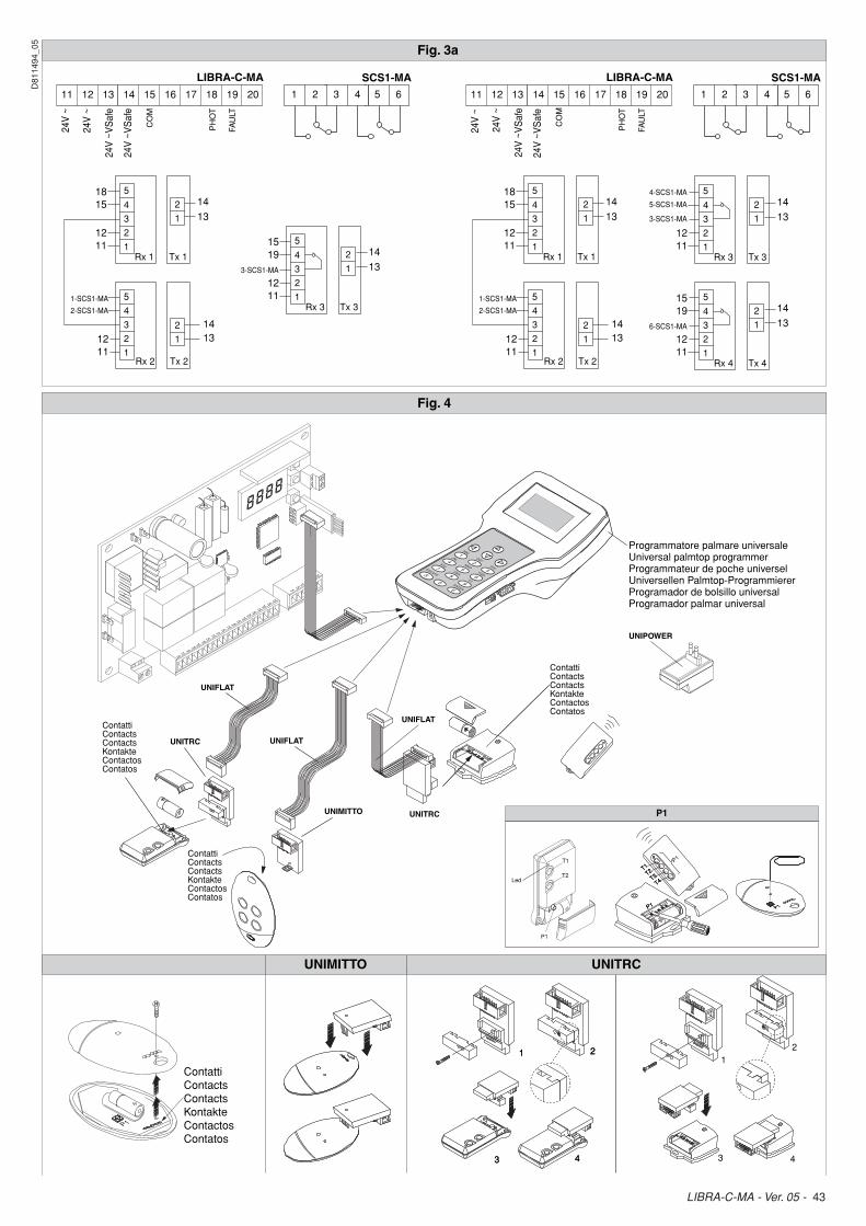
means of 1 wire only (PHOBOS BT, IGEA BT).*9-10 Connection to blinker (24V~ 20W max) 11-12 Output 24V~ 180mA max - supply to photocells or other devices.13-14 Output 24V~ V safe 180mA max - supply to photocell transmitters
with checking function (Fig.3a).
12 - LIBRA-C-MA - Ver. 05
D81
1494
_05

INSTALLATION MANUAL ENGLISh
15-16 START pushbutton (N.O.).15-17 STOP pushbutton (N.C.). If not used, leave the bridge 15-17 con-
nected. 15-18 Photocell input (N.C.). If not used, leave the bridge 15-18 con-
nected. 15-19 Fault input (N.O.). Input for photocells provided with checking N.O.
contact (Fig. 3a). 15-20 Pedestrian pushbutton input (N.O.). Activation is carried out by motor
2; if the opening cycle has started (not from pedestrian function), the pedestrian command has no effect.
21-22 Output for gate-open warning light output (N.O. contact (24V~/1A max)) or alternatively 2nd radio channel (see paragraph 6 on “Con-figuration”).
23 Limit switch common terminal24 Motor 2 opening limit switch for actuators with separate limit switches*25 Motor 2 closing limit switch for actuators with separate limit switches*26 Motor 1 opening limit switch for actuators with separate limit switches* 27 Motor 1 closing limit switch for actuators with separate limit switches*29-30 Antenna input for radio-receiver plug-in board (29 signal–30 braid).* When using the limit switches connected to terminals 5 and 8, leave the jumpers at terminals 24-25-26-27. When using the limit switches connected to terminals 24-25-26-27, provide jumpers between terminals 5-15 and 8-15.
5) PROGRAMMINGThe control panel provided with a microprocessor is supplied with function parameters preset by the manufacturer, suitable for standard installations. The predefined parameters can be altered by means of either the incorporated display programmer or universal palmtop programmer.In the case where programming is carried out by means of universal palmtop programmer, carefully read the instructions relating to universal palmtop programmer, and proceed in the following way.Connect the universal palmtop programmer to the control unit through the UNIFLAT and UNIDA accessories (See fig. 4). The LIBRA-C-MA control unit does not supply the universal palmtop programmer with power, and therefore requires an appropriate supply unit.Enter the “CONTROL UNITS” menu, and the “PARAMETERS” submenu, then scroll the display screenfuls using the up/down arrows to set the numerical values of the parameters listed below.For the function logics, refer to the “LOGIC” submenu.In the case where programming is carried out by means of the incorporated programmer, refer to Fig. A and B and to the paragraph on “Configuration”.
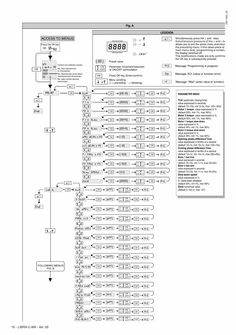
6) CONFIGURATIONThe display programmer is used to set all the LIBRA-C-MA control panel functions.The programmer is provided with three pushbuttons for menu scrolling and function parameter configuration: + menu scrolling/value increment key - menu scrolling/value reduction keyOK Enter (confirm) keyThe simultaneous pressure of the + and - keys is used to exit the active menu and move to the preceding menu. The modifications made are only set if the OK key is subsequently pressed.When the OK key is pressed for the first time, the programming mode is entered. The following pieces of information appear on the display at first:- Control unit software version- Number of total manoeuvres carried out (the value is expressed in
thousands, therefore the display constantly shows 0000 during the first thousand manoeuvres)
- Number of manoeuvres carried out since the latest maintenance opera-tion (the value is expressed in thousands, therefore the display constantly shows 0000 during the first thousand manoeuvres)
- Number of memorised radio control devices.When the OK key is pressed during the initial presentation phase, the first menu can be accessed directly.Here follows a list of the main menus and the respective submenus available.The predefined parameter is shown between square brackets [ 0 ].The writing appearing on the display is indicated between round brackets.Refer to Figures A and B for the configuration procedure.
6.1) PARAMETER MENU (PARAm)- Automatic Closing Time (TCA) [ 10s ] Set the numerical value of the automatic closing time from 3 to 120
seconds. - Motor 1 torque (Mot1 torque) [ 50% ] (Advanced parameters ⇒ address 3) Set the numerical value of the motor 1 torque between 1% and 99%.- Motor 2 torque (Mot 2 torque) [ 50% ] (Advanced parameters ⇒ address 4) Set the numerical value of the motor 2 torque between 1% and 99%.
- Motor 1 slow-down torque (m1 t slow) [ 45% ] (Advanced parameters ⇒ address 8) Set the numerical value for slow-down torque of motor 1 between 1%
and 99%.- Motor 2 slow-down torque (m2 t slow) [ 45% ] (Advanced parameters ⇒ address 9) Set the numerical value for slow-down torque of motor 2 between 1%
and 99%. NOTE: In case of obstacle detection, the Ampere-stop function halts
the leaf movement, reverses its motion for 1 sec. and then halts in the STOP status.
WARNING: Check that the impact force value measured at the points established by the EN 12445 standard is lower than
that specified in the EN 12453 standard.Incorrect sensitivity setting can cause injuries to persons or animals, or damage to things.
- Opening delay time (open delay time) [ 1s ] Set the opening delay time for motor 1 relative to motor 2, between 1 and
10 seconds. - Closing delay time (cls delay time) [ 1s ] Set the closing delay time for motor 2 relative to motor 1, between 1 and
25 seconds.- Motor 1 fast time (Motor 1 fast time ( (m1 fast time) [ 15s ] (Advanced parameters ⇒ address 6) Set the time to normal speed (not slowed down), ranging from 1 to 30
seconds. Carry out the settings from the gate-closed position; if settingsCarry out the settings from the gate-closed position; if settings are carried out from a different point, they will become effective as from the subsequent opening manoeuvre.
- Motor 2 fast time (Motor 2 fast time ( (m2 fast time) [ 15s ] (Advanced parameters ⇒ address 7) Set the time to normal speed (not slowed down), ranging from 1 to 30
seconds. Carry out the settings from the gate-closed position; if settingsCarry out the settings from the gate-closed position; if settings are carried out from a different point, they will become effective as from the subsequent opening manoeuvre.
Note: The slow-down time, on closing and on opening, is obtained by timing one manoeuvre and setting a minimum value for this parameter. If, for example, one manoeuvre lasts 25 seconds, a setting of “normal speed time” to 20s will produce a slow-down time of 5s both on closing and on opening.
- Slow-down speed (slov speed) [ 50% ] (Advanced parameters ⇒ address 5) Set the slow-down speed: Sets the slow-down speed percentage between 0% and 99% of normal
speed. 0 – slow-down disabled (always fast).0 – slow-down disabled (always fast).(always fast).- Zone (zone) [ 0 ] Set the zone number between a minimum value of 0 and a maximum
value of 127. See paragraph 7 on “Serial connection”.
6.2) LOGIC MENU (logic.)- TCA (TCA) [ OFF ]ON : Activates automatic closingOFF:Excludes automatic closing - 3 Steps (3 step) [ OFF ]ON: Enables 3-step logic. A Start impulse has the following effects: door closed: ................................................................................opens
on opening: .................................stops and enters TCA (if configured) door open: ................................................................................. closes on closing: ...............................................................stops and reopensOFF:Enables 4-step logic. A Start impulse has the following effects: door closed: ................................................................................opens on opening: .................................stops and enters TCA (if configured) door open: ................................................................................. closes on closing: ...................................stops and does not enter TCA (stop) after stopping: .............................................................................opens- Impulse lock (ibl open) [ OFF ]ON : The Start impulse has no effect during the opening phase.OFF:The Start impulse becomes effective during the opening or closing phase. - Rapid closing (fast cls) [ OFF ]ON: Closes the gate after 3 seconds from photocell disengagement
before waiting for the end of the TCA set.OFF:Command not entered. - Photocells on opening (photc. open) [ OFF ] (Advanced logics ⇒ address 14) ON: In case of obscuring, this excludes photocell operation on opening.
During the closing phase, it immediately reverses the motion.OFF:In case of obscuring, the photocells are active both on opening and on
closing. When a photocell is obscured on closing, it reverses the motion only after the photocell is disengaged.
- Photocell test (test phot) [ OFF ] ON: Activates photocell check OFF:Deactivates photocell check
LIBRA-C-MA - Ver. 05 - 13
D81
1494
_05
INSTALLATION MANUALENGLISh
If this setting is not activated (OFF), it inhibits the photocell checking function, allowing connection of devices not provided with additional checking contact.
- Gate-open or 2nd radio channel warning light (SCA 2ch) [ OFF ]ON: The output between terminals 21 and 22 is configured as Gate-open
warning light, in this case the 2nd radio channel controls pedestrian opening.
OFF:The output between terminals 21 and 22 is configured as 2nd radio channel.
- Motors in operation (1 mot ON) [ OFF ]ON: Only motor 2 is in operation (terminals 3, 4 and 5). With this configuration, the pedestrian input is disabled.OFF:Both motors are in operation.- Lock hold (block persist) [ OFF ] (Fig. 5)ON: To be used when the mechanical closing backstop is fitted. This function activates leaf pressure on the mechanical backstop, without
this being considered as an obstacle by the Ampere-stop sensor. Therefore the rod continues its travel for another 0.5 sec. after detecting
the closing limit switch or upon reaching the mechanical backstop. So by activating the closing limit switches slightly earlier, the leaves will come to a perfect halt against the backstop. (Fig. 5a)
OFF:To be used when no mechanical closing backstop is fitted. Movement is exclusively halted by activation of the closing limit switches;
in this case proceed to carrying out precise setting of the closing limit-switch activation. (Fig. 5b)
- hold-to-run control (hold-to-run) [ OFF ]ON: Hold-to-run operation: the manoeuvre continues as long as the control
key is kept pressed. WARNING!: Enabling the Hold-to-run logic entails a different use of the
START and PEDESTRIAN buttons: START takes on the hold-to-run OPEN function PEDESTRIAN takes on the hold-to-run CLOSE functionOFF:Impulse operation, according to the 3 or 4 step logic.- Fixed code (fixed code) [ OFF ] (Advanced logics ⇒ address 13)ON: The receiver is configured for operation in fixed-code mode, see para-
graph on “Radio Transmitter Cloning”.OFF:The receiver is configured for operation in rolling-code mode, see
paragraph on “Radio Transmitter Cloning”.- Radio transmitter programming (radio prog) [ ON ] (Advanced logics ⇒ address 15)ON: This enables transmitter storage via radio: 1 – First press the hidden key (P1) and then the normal key (T1, T2, T3
or T4) of a transmitter already memorised in standard mode by means of the radio menu.
2 – Within 10s press the hidden key (P1) and the normal key (T1, T2, T3 or T4) of a transmitter to be memorised.
The receiver exits the programming mode after 10s, other new transmit-ters can be entered before the end of this time.
This mode does not require access to the control panel.OFF:This disables transmitter storage via radio. The transmitters can only be memorised using the appropriate Radio
menu.- Master/Slave (Master) [ OFF ]ON: The control panel is set as Master in a centralised connection (see
Paragraph 7). OFF:The control panel is set as Slave in a centralised connection (see
Paragraph 7).- Start-Open selection (start - open) [ OFF ]ON: The input between the two terminals 15-16 acts as open. For closing,
wait until the TCA, which has to be previously enabled, has elapsed.OFF:The input between the two terminals 15-16 acts as start.- Prealarm (pre-alarm) [ OFF ]ON: The blinker comes on 3 sec. before the motors start.OFF:The blinker comes on at the same time as the motors start.- Automatic fast time (auto fast time) [ ON ]ON: The control unit automatically calculates slow-down time and offsets fast
time to keep slow-down time constant. With this function active, the fast time value is continually updated (it is therefore possible to find a setting other than the one actually carried out).
OFF:The control unit does not offset fast time, but applies the preset «fast time» parameter, independently of any environmental changes.
6.3) RADIO MENU (RADIO)- Add Allows you to add one key of a radio control device to the receiver memory;
after storage it displays a message showing the receiver number in the memory location (from 01 to 64).
Add Start button (add start) associates the required key to Start command Add 2ch button (add 2ch) associates the required key to 2nd radio channel
- Read (read) Checks one key of a receiver; if stored it displays a message showing
the receiver number in the memory location (from 01 to 64), and the key number (T1, T2, T3 or T4).
- Eliminate list (erease 64) WARNING! Completely removes all memorised radio control devices
from the receiver memory. - Receiver code reading (RX code) This displays the code entered in the receiver (par. 11).Consult paragraphs 8, 9, 10 and 11 for further information concerning the advanced functions of the Clonix incorporated receiver.
6.4) LANGUAGE MENU (language)Allows you to set the language on the display programmer.- ITALIAN (ITA) - FRENCh (FRA) - GERMAN (DEU)- ENGLISh (ENG) - SPANISh (ESP)
6.5) DEFAULT MENU (default)Restores the preset default values on the control unit. After restoring, a new autoset operation must be carried out. 6.6) DIAGNOSTICS AND MONITORINGThe display on the LIBRA-C-MA panel shows some useful information, both during normal operation and in the case of malfunctions.Diagnostics:In the case of malfunctions, the display shows a message indicating which device needs to be checked:STRT = START input activationSTOP = STOP input activationPHOT = PHOT input activationFLT = FAULT input activation for checked photocells TH = Activation of software thermal protectionER 1 = Board error during safety device checkER 2 = Board error during safety device checkWhen using traditional limit switches connected to terminals 24-25-26-27:SWO1 = activation of Motor 1 opening limit switch inputSWC1 = activation of Motor 1 closing limit switch inputSWO2 = activation of Motor 2 opening limit switch inputSWC2 = activation of Motor 2 closing limit switch inputIn the case where an obstacle is found, the LIBRA-C-MA panel stops the door and activates a reverse manoeuvre; at the same time the display shows the “AMP” message.
Monitoring:During the opening and closing phases, the display shows four digits sepa-rated by a dot, for example 35.40. The digits are constantly updated during the manoeuvre, and represent the maximum torque reached by motor 1 (35) and motor 2 (40).These values allow the torque setting to be corrected.If the maximum torque value reached during the manoeuvre gets sensibly close to the value set in the parameter menu, malfunctions may occur in the future following wear or slight door deformation.It is therefore advisable to check the maximum torque reached during some of the manoeuvres carried out in the course of installation, and if necessary set a value about 15-20 percent points higher in the parameter menu.
6.7) ADJUSTING PROCEDURE- Before switching on, check electrical connections.- Set the following parameters: Automatic Closing Time, Opening and closing
delay times, Slow-down speed and Zone number.- Set all the logics.- Carry out the autoset procedure.After completing the autoset procedure, the Motor fast time and the Torque can be manually adjusted.WARNING! Any incorrect setting can cause injuries to persons and animals or damage to things.
WARNING: Check that the impact force value measured at the points established by the EN 12445 standard is lower than that
specified in the EN 12453 standard.To obtain a better result, it is advisable to carry out the autoset procedure and the fast time setting with the motors at rest (i.e. not overheated by a considerable number of consecutive manoeuvres).
6.8) AUTOSET MENU (autoset)Allows you to automatically set the Motor torque. WARNING! The autosetting operation is carried out from closing end-of-stroke devices. If Autoset is commanded in a different position an error message indicating “nsvc” will be displayed and the required manoeuvre will not take place.
14 - LIBRA-C-MA - Ver. 05
D81
1494
_05
INSTALLATION MANUAL ENGLISh
WARNING!! The autoset operation is only to be carried out after checking the exact leaf (opening/closing) movement, and correct limit-switch activation.Set the adequate slow-down speed: by pressing OK the message “.... .... ....” is displayed and the control unit commands an opening manoeuvre without slow-down, followed by a closing manoeuvre without slow-down during which the duration of the stroke is memorised. Then, the control unit commands a second opening manoeuvre with slow-down followed by a second closing manoeuvre with slow-down during which the minimum torque value neces-sary for the movement of the leaf is automatically set. During this phase, it is important to avoid obscuring the photocells, as well as using the START, STOP, PED, CLOS or OPEN commands and the display. After completion, if the Autoset was successful, an “OK” message will be displayed on the control unit which will then return to the Autoset menu after pressing the “OK” key.If, on the other hand, the control unit displays the “KO” message, it means that the autoset procedure has not been successfully completed; it is thus necessary to check the wear condition of the gate and the regular movement of the leaves before proceeding to a new autoset operation. WARNING! During the autoset phase, the obstacle detection function is not active, therefore the installer must control the automation movement and prevent persons and things from approaching or standing within the automation working range. In the case where buffer batteries are used, autosetting must be carried out with the control panel supplied by mains power voltage.
WARNING: The torque values fixed by means of the autoset pro-cedure refer to the slow-down speed fixed during the same pro-
cedure. If the slow-down speed is changed, a new autoset procedure must be carried out.
WARNING: Check that the impact force value measured at the points established by the EN 12445 standard is lower than that
specified in the EN 12453 standard.Incorrect sensitivity setting can cause injuries to persons or animals, or damage to things.
7) STATISTICSHaving connected the universal palmtop programmer to the control unit, enter the CONTROL UNIT / STATISTICS menu and scroll the screenful showing the statistical parameters:- Board microprocessor software version.- Number of cycles carried out. If motors are replaced, count the number
of manoeuvres carried out up to that time. - Number of cycles carried out from the latest maintenance operation. It is automatically set to zero after each self-diagnosis or parameter
writing. - Date of latest maintenance operation. To be updated manually from the
appropriate menu “Update maintenance date”.- Installation description. 16 characters can be entered for installation
identification.
8) INTEGRATED RECEIVER TEChNICAL SPECIFICATIONReceiver output channels: - output channel 1, if activated, controls a START command. - output channel 2, if activated, controls the excitation of the 2nd radio
channel relay for 1s.Transmitter versions which can be used:all Rolling Code transmitters compatible with .
ANTENNA INSTALLATIONUse an antenna tuned to 433Mhz.For Antenna-Receiver connection, use RG8 coaxial cable.The presence of metallic masses next to the antenna can interfere with radio reception. In case of insufficient transmitter range, move the antenna to a more suitable position.9) RECEIVER CONFIGURATIONThe on-board receiver combines characteristics of utmost safety in copying variable code (rolling code) coding with the convenience of carrying out transmitter “cloning” operations thanks to an exclusive system.Cloning a transmitter means creating a transmitter which can be automatically included within the list of the transmitters memorised in the receiver, either as an addition or as a replacement of a particular transmitter.Cloning by replacement is used to create a new transmitter which takes the place of the one previously memorised in the receiver; in this way a specific transmitter can be removed from the memory and will no longer be usable.Therefore it will be possible to remotely program a large number of additional transmitters or, for example, replacement transmitters for those which have been lost, without making changes directly to the receiver. When coding safety is not a decisive factor, the on-board receiver allows you to carry out fixed-code additional cloning which, although abandoning the variable code, provides a high number of coding combinations, there-fore keeping it possible to “copy” any transmitter which has already been programmed.
PROGRAMMINGTransmitter storage can be carried out in manual mode or by means of the universal palmtop programmer which allows the complete installation database to be managed through the Eedbase software.In this second case, receiver programming takes place through the connection of universal palmtop programmer to the LIBRA-C-MA control panel, using the UNIFLAT and UNIDA accessories as indicated in Fig. 4.
10) MANUAL PROGRAMMINGIn the case of standard installations where advanced functions are not required, you can proceed to manual storage of the transmitters, making reference to fig. B for basic programming.- If you wish the transmitter to activate output 1 (START) by means of key1,
key2, key3 or key4, enter the transmitter in menu “Start key”, as in fig. B.- If you wish the transmitter to activate output 2 (2nd radio channel relay)
by means of key1, key2, key3 or key4, enter the transmitter in menu “2nd ch. key”, as in fig. B.
Note: Hidden key P1 appears differently depending on the transmitter model.
For transmitters with hidden key, press hidden key P1 (fig. B1). For transmit-ters without hidden key, the key P1 function corresponds to simultaneously pressing the 4 transmitter keys or, after opening the battery compartment, bridging the two P1 points by means of a screwdriver (fig. B2).
IMPORTANT NOTE: ATTACh ThE ADh ESIVE KEY LABEL TO ThE FIRST MEMORISED TRANSMITTER (MASTER). In the case of manual programming, the first transmitter assigns the key code to the receiver; this code is necessary in order to carry out subsequent cloning of the radio transmitters.
11) RADIO-TRANSMITTER CLONINGRolling-code cloning / Fixed-code cloningMake reference to the universal palmtop programmer Instructions and the CLONIX Programming Guide.
11.1) ADVANCED PROGRAMMING: COLLECTIVE RECEIVERSMake reference to the universal palmtop programmer Instructions and the CLONIX Programming Guide.
12) SERIAL CONNECTION USING SCS1 BOARD (Fig.6) The LIBRA-C-MA control panel allows several automation units (SCS1) to be connected in a centralised way by means of appropriate serial inputs and outputs. This makes it possible to use one single command to open and close all the automation units connected.Following the diagram in Fig.6, proceed to connecting all the LIBRA-C-MA control panels, exclusively using a telephone-type line. Should a telephone cable with more than one pair be needed, it is indispens-able to use wires from the same pair.The length of the telephone cable between one appliance and the next must not exceed 250 m.At this point, each of the LIBRA-C-MA control panels must be appropriately configured, by setting a MASTER unit first of all, which will have control over all the others, to be necessarily set as SLAVE (see logic menu). The MASTERThe MASTER control unit must be the first one of the series (Fig. 6).Also set the Zone number (see parameter menu) between 0 and 127. The zone number allows you to create groups of automation units, each one answering to the Zone Master unit. Each zone can only be assigned one Master unit, the Master unit in zone 0 also controls the Slave units in the other zones.
13) SCRAPPINGWarning: This operation should only be carried out by qualified person-nel. Materials must be disposed of in conformity with the current regulations. In case of scrapping, the automation devices do not entail any particular risks or danger. In case of materials to be recycled, these should be sorted out by type (electrical components, copper, aluminium, plastic etc.).
14) DISMANTLINGWarning: This operation should only be carried out by qualified person-nel. When the control unit is disassembled to be reassembled on another site, proceed as follows: • Disconnect the power supply and the entire electrical installation. • In the case where some of the components cannot be removed or are
damaged, they must be replaced.
The descriptions and illustrations contained in the present manual are not binding. The Company reserves the right to make any alterations deemed appropriate for the technical, manufacturing and commercial improvement of the product, while leaving the essential product fea-tures unchanged, at any time and without undertaking to update the present publication.
LIBRA-C-MA - Ver. 05 - 15
D81
1494
_05
16 - LIBRA-C-MA - Ver. 05
D81
1494
_05

LIBRA-C-MA - Ver. 05 - 17
D81
1494
_05

1 2 3 4 5 6 7 8 9 10 11121314151617181920 21 22 23 24 25 26 28
2930
27
Fig. 2
Fig. 3
Fig. 1
OK
236
194
SD
Fig. 3a
11 12 13 14 15 16 17 18 19 20
CO
M
PH
OT
FAU
LT
24V
~
24V
~V
Saf
e
Rx 1 Rx 2
Tx 1 Tx 2
1 2 3 4 5
1 2 1 2
1 2 3 4 5
11 12 13 14 15 16 17 18 19 20
CO
M
PH
OT
FAU
LT
24V
~
24V
~V
Saf
e
Rx 1
Tx 1
1 2 3 4 5
1 2
100
9 101 2
L
+
FC
M2*
FC
M1*
N
3 4 5 6 7 8
M2
25W
max
.
230V ~
+
M1
11 12 13 14 15 16 17 18 19 20
STA
RT
CO
M
NO
NC
NC
NO
NO
STO
P
ANT.
PE
D
PH
OT
FC
A M
2
CO
M F
C
FC
C M
2
FC
A M
1
FC
C M
1
FAU
LT
AN
T
SH
IELD
21 22 29 30
24V ~ 24V ~VSafe
23 24 25 26 27 28
11 12 21
SCA
22
19 20 21 22
24 V
~
Controllo finecorsa negli attuatori con ges t ione f i necorsa con 1 so lo f i l o (PHOBOS BT, IGEA BT).
Limit switch control for actuators with limit switch control by means of 1 wire only (PHOBOS BT, IGEA BT).
C o n t r ô l e f i n d e c o u r s e d a n s l e s act ionneurs avec gest ion de f in de course avec un seul fil (PHOBOS BT, IGEA BT).
Endschalter-Kontrolle in Antrieben mit 1-Draht-Endschaltersteuerung (PHOBOS BT, IGEA BT).
Control de los fines de carrera en los servomotores con gestión de los fines de carrera con 1 solo hilo (PHOBOS BT, IGEA BT).
C o n t r o l o d o f i m - d e - c u r s o n o s accionadores com gestão do fim-de-curso com 1 único fio (PHOBOS BT, IGEA BT).
*
*
*
*
*
*
F1A25T
F 1AT (230V)F 2AT (110V)
42 - LIBRA-C-MA - Ver. 05
D81
1494
_05
Programmatore palmare universaleUniversal palmtop programmerProgrammateur de poche universelUniversellen Palmtop-ProgrammiererProgramador de bolsillo universalProgramador palmar universal
LIBRA-C-MA LIBRA-C-MA
P1P1
P1
ContattiContactsContactsKontakteContactosContatos
Fig. 4
UNITRC UNIFLAT
1
3 4
2
Fig. 4
Fig. 3a
ContattiContactsContactsKontakteContactosContatos
ContattiContactsContactsKontakteContactosContatos
ContattiContactsContactsKontakteContactosContatos
1
3 4
21
2
3 4
P1
T1
LedT2
P1
P1
T1T2
T3T4
P1
P1
T1T2
T3T4
UNIPOWER
UNIFLAT
UNIFLAT
UNIMITTO UNITRC
UNIMITTO UNITRC
CO
M
11 12 13 14 15 16 17 18 19 20
PH
OT
FAU
LT
24V
~
24V
~
24V
~V
Saf
e
24V
~V
Saf
e
1314
1314
1815
1-SCS1-MA
3-SCS1-MA
2-SCS1-MA
1211
1211 15
19
1211
Rx 2
Rx 1
Tx 2
Tx 1
1
2
3
4
5
1
2
1
2
1
2
3
4
1314
Rx 3 Tx 3
5
5
1
2
1
2
3
4
SCS1-MA
1 2 3 4 5 6
CO
M
11 12 13 14 15 16 17 18 19 20
PH
OT
FAU
LT
24V
~
24V
~
24V
~V
Saf
e
24V
~V
Saf
e
1314
1314
1815
1-SCS1-MA
6-SCS1-MA
2-SCS1-MA
1211
1211
1519
1211
Rx 2
Rx 1
Tx 2
Tx 1
1
2
3
4
5
1
2
1
2
1
2
3
4
1314
Rx 4 Tx 4
5
5
1
2
1
2
3
4
1314
4-SCS1-MA
5-SCS1-MA
3-SCS1-MA
1211
Rx 3 Tx 3
5
1
2
1
2
3
4
SCS1-MA
1 2 3 4 5 6
LIBRA-C-MA - Ver. 05 - 43
D81
1494
_05

Fig. 5
0,5s
A
BFig. 6
SBS
SBS
LIBRA-C-MA
33
3355
230V (*)
25V44
33
(*) 110V
--
++
12V, 1.2 AH
12V, 1.2 AH
++--334455
JP1 3
12
456
Rosso
-Red
-Rou
ge-R
ot-R
ojo
Verm
elh
o
LIBRA-C-MA
11 12 13 14 15 16 17 18 19 20
STA
RT
CO
M
NO
NC
NC
NO
NO
STO
P
PE
D
PH
OT
FAU
LT
24V= 24V=VSafe
+ +- -
SCS1 SCS1 SCS1
MASTER
Max. 250m
TX
1
TX
2
RX
1
RX
2
TX
1
TX
2
RX
1
RX
2
TX
1
TX
2
RX
1
RX
2
SCS1