Embed Size (px)
Citation preview

HMI HMI HMI HMI –––– Automação e Instrumentação, Lda.Automação e Instrumentação, Lda.Automação e Instrumentação, Lda.Automação e Instrumentação, Lda.
Rua dos 5 Caminhos, nº 570 4780-382 Santo Tirso PORTUGAL Web: www.hmi.pt
Tel. +351 252 850 501 Fax. +351 300 013 487
Email: [email protected]
FICHA TÉCNICA DE PRODUTO
PRODUCT DATASHEET
MS41Magnetic Level Gauge Switch
Data sheet DS/MS41-EN Rev. K
Magnetically actuated 10 amp hermetically sealed electric switchK-TEK Products
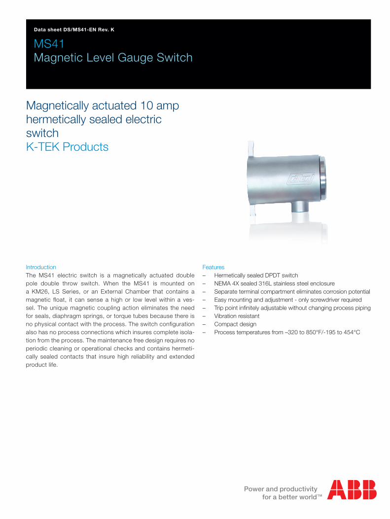
IntroductionThe MS41 electric switch is a magnetically actuated double pole double throw switch. When the MS41 is mounted on a KM26, LS Series, or an External Chamber that contains a magnetic float, it can sense a high or low level within a ves-sel. The unique magnetic coupling action eliminates the need for seals, diaphragm springs, or torque tubes because there is no physical contact with the process. The switch configuration also has no process connections which insures complete isola-tion from the process. The maintenance free design requires no periodic cleaning or operational checks and contains hermeti-cally sealed contacts that insure high reliability and extended product life.
Features – Hermetically sealed DPDT switch – NEMA 4X sealed 316L stainless steel enclosure – Separate terminal compartment eliminates corrosion potential – Easy mounting and adjustment - only screwdriver required – Trip point infinitely adjustable without changing process piping – Vibration resistant – Compact design – Process temperatures from –320 to 850°F/-195 to 454°C

2 MS41 Magnetic Level Gauge Switch | Data sheet
SPECIFICATIONS
Switch
Switch Type Magnetically actuated, cam driven snap action bistable switch; DPDTSwitch Action Break before makeMax Deadband Approximately ±0.75” of float travelContact Rating
Material Silver-Cadmium AlloyAC Rating Max - 10 amp resistive, 1/4 HP @ 125 AC or 250 VAC and less than 187 WattsDC Rating 2.6 amp @ 24 VDC, 1/2 amp @ 125 VDC, 1/4 amp @ 250 VDCLamp Load Rating 1.5A @ 125 VAC
Process Temperature
Switch Ambient Temperature
-60 to 300°F / -51 to 149°C Standard;-320 to 850°F / -195 to 454°C with options-58 to 176°F / -50 to 100°C (max. ambient temp. de-rated depending on approval rat-ing, see below)
Housing
Material 316L Stainless Steel, Dual Compartment Housing, NEMA 4X Electrical Connections 3/4” FNPT conduit and terminal block with #6 screwsApprovals FM & CSA Explosion Proof Ratings:
CL I / Div 1&2 / GP ABCD / DIP CL II / Div 1&2 /GP EFG, CL III FM: CL I, Zn 1, AEx d IIC CSA: CL I, Zn 1, Ex d IIC Housing: NEMA 4X OR TYPE 4X FM & CSA IS Ratings: CL I / Div 1 / ABCD; CL II / Div 2 / EFG CL I / Div 2 / ABCD; CL II / Div 2 / FG; CL III FM: CL 1, Zn 0, AEx, ia, IIC CSA: CL 1, Zn 0, Ex, ia, IIC
ATEX Flameproof: II 2GD T85°C EEx d IIC T6 (-50°C ≤ Tamb ≤ 65°C); 03 ATEX 132366Intrinsically Safe: II 1GD T85°C EEx ia IIC T6 (-50°C ≤ Tamb ≤ 80°C); 03 ATEX 136189
GOST Russia: 0ExiaIICT6, 1ExdCT6
IEC:Intrinsic Safety Ex ia IIC T6 (-50°C Tamb 80°C), Ex iaD 20/21 IP6X T85°C (-50°C Tamb 80°C)Flameproof: II 2 G/D Ex d IIC T6 (-50°C ≤ Tamb ≥ 65°C)Ex tD A21 T80°C
Data sheet | MS41 Magnetic Level Gauge Switch 3
ORDERING INFORMATION:MS41 / a / b / c:/a Mounting
S Standard up to 300°F / 149°CIH Includes Switch Insulation Pad; Process Temperatures up to 600°F / 315°CRD Includes Rod Mount Brackets for use with insulated KM26 Magnetic Level Gauges or ST95 Seal Fluid
Supply Tanks with Switch Rods; Process Temperatures up to 850°F / 454°C/b Electrical Connection
F7 3/4” FNPT StandardM2 M20 Adapter
/c Approvals X NoneFMX Factory Mutual System (FM) and Canadian Standards Association (CSA) Flameproof FMI Factory Mutual System (FM) and Canadian Standards Association (CSA) Intrinsically SafeCEX ATEX Flameproof CEI ATEX Intrinsically Safe GR GOST RussiaIEI International Electromechanical Commission I.S.IEX International Electromechanical Commission Flameproof
Note: Contact Factory for Special Application Requirements
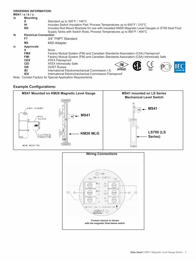
MS41 Mounted on KM26 Magnetic Level Gauge MS41 mounted on LS Series Mechanical Level Switch
Wiring Connections
Contact closure is shown with the magnetic float below switch
Example Configurations:
KM26 MLG
MS41
MS41
LS700 (LS Series)

HMI HMI HMI HMI –––– Automação e Instrumentação, Lda.Automação e Instrumentação, Lda.Automação e Instrumentação, Lda.Automação e Instrumentação, Lda.
Rua dos 5 Caminhos, nº 570
4780-382 Santo Tirso
PORTUGAL
Web: www.hmi.pt
Tel. +351 252 850 501
Fax. +351 300 013 487
Email: [email protected]
Our offering:
Actuators and
Positioners
Analytical Instruments
Device Management,
Fieldbus and Wireless
Flow Measurement
Force Measurement
Level Measurement
Natural Gas
Measurement
Pressure Measurement
Recorders and
Controllers
Temperature
Measurement

DS
/MS
41-E
N R
ev.
K
06
.201
2
Contact us
NoteWe reserve the right to make technical changes or modify the contents of this document without prior notice. With regard to purchase orders, the agreedparticulars shall prevail. ABB does not accept any responsibility whatsoever for potential errors or possible lack of information in this document.
We reserve all rights in this document and in the subject matter and illustrations contained therein. Any reproduction, disclosure to third parties or utilization of its contents - in whole or in parts – is forbidden without prior written consent of ABB.
Copyright© 2012 ABBAll rights reserved
ABB Inc. 18321 Swamp RoadPrairieville, LA 70769 USAPhone: +1 225 673 6100Service: +1 225 677 5836Fax: +1 225 673 2525Service e-mail: [email protected]
www.abb.com/level