Embed Size (px)
Citation preview

TENSION ROD
TIRANTEFT

A S-Vitech – Technical Glass Fitting foi especificamente pensada, desenvolvida e produzida para soluções de fixação de vidro, nomeadamente:
• Fachadas ventiladas;• Muros cortina ou fachadas agrafadas;• Coberturas e clarabóias;• Canopias.
O fator estético e arquitetónico estão na génese de todo o conceito, e a qualidade dos materiais e acabamento dos produtos, consolidam-no.
Toda a linha está desenvolvida em aço inox, com particular preocupação pelo detalhe e fiabilidade.
A facilidade na aplicação e manuseamento dos materiais foram igualmente fatores primordiais no desenvolvimento dos produtos.
Assim, o vidro e o inox doravante unos!
S-Vitech – Technical Glass Fitting was specially conceived, developed and produced for glass fastening solutions, namely:
• Ventilated facade;• Curtain walls or stapled facade;• Roofs and skylights;• Canopies.
Aesthetics and architecture are in the basis of the overall concept and the quality of the materials as well as the finishing of the products is its wrapping up.
All our products are made in stainless steel with a special attention to details and reliability.
Other important factors are the easy application and usage of materials.
Glass and stainless steel are therefore inseparable!
Tension rod M6 lenght 1000 - 3000 mmTirante M6 comprimento 1000 - 3000 mm
FT 5006
Tension rod M10 lenght 1000 - 3000 mmTirante M10 comprimento 1000 - 3000 mm
FT 5010
Tension rod M12, lenght 1000 - 3000 mmTirante M12 comprimento 1000 - 3000 mm
FT 5012
Tension rod M16 lenght 1000 - 3000 mmTirante M16 comprimento 1000 - 3000 mm
FT 5016
Tension rod M20 lenght 1000 - 3000 mmTirante M20 comprimento 1000 - 3000 mm
FT 5020
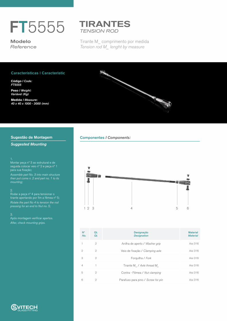
Tension rod M_ lenght by measureTirante M_ comprimento por medida
FT 5555
Tension rod M16 L, lenght 1000 - 3000 mm in tubeTirante M16 comprimento 1000 - 3000 mm corpo em tubo
FT 5116
Tension rod M24 lenght 1000 - 3000 mmTirante M24 comprimento 1000 - 3000 mm
FT 5024
Tension rod M30 lenght 1000 - 3000 mmTirante M30 comprimento 1000 - 3000 mm
FT 5030
Tension rod M39 lenght 1000 - 3000 mmTirante M39 comprimento 1000 - 3000 mm
FT 5039
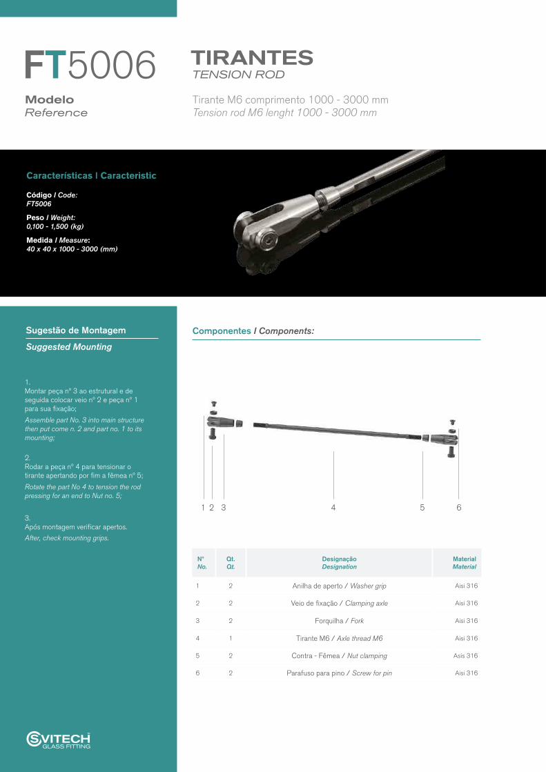
Componentes I Components:Sugestão de Montagem
Suggested Mounting
TENSION RODTIRANTES
ModeloReference
FT5006
Nº No.
Qt. Qt.
Designação Designation
Material Material
1 2 Anilha de aperto / Washer grip Aisi 316
2 2 Veio de fixação / Clamping axle Aisi 316
3 2 Forquilha / Fork Aisi 316
4 1 Tirante M6 / Axle thread M6 Aisi 316
5 2 Contra - Fêmea / Nut clamping Asis 316
6 2 Parafuso para pino / Screw for pin Aisi 316
1. Montar peça nº 3 ao estrutural e de seguida colocar veio nº 2 e peça nº 1 para sua fixação;
Assemble part No. 3 into main structure then put come n. 2 and part no. 1 to its mounting;
2. Rodar a peça nº 4 para tensionar o tirante apertando por fim a fêmea nº 5;
Rotate the part No 4 to tension the rod pressing for an end to Nut no. 5;
3. Após montagem verificar apertos.
After, check mounting grips.
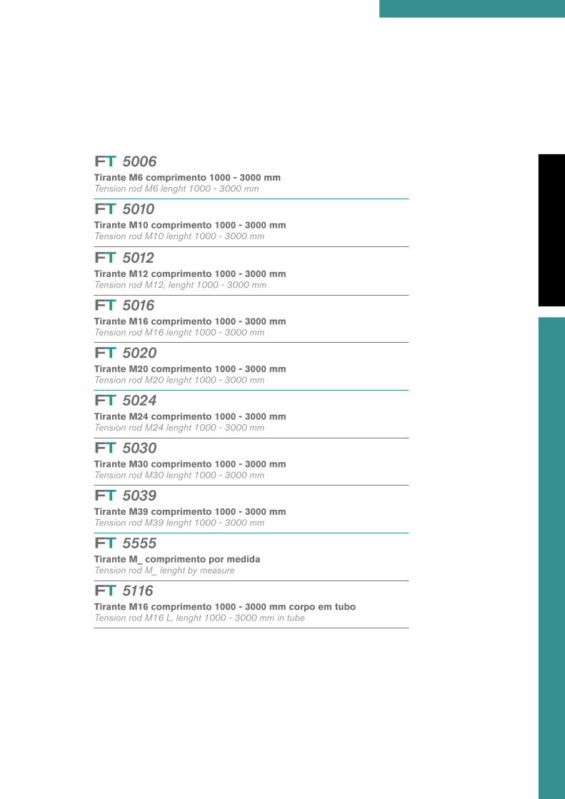
Características I Caracteristic
Tension rod M6 lenght 1000 - 3000 mmTirante M6 comprimento 1000 - 3000 mm
Código I Code:FT5006
Peso I Weight: 0,100 - 1,500 (kg)
Medida I Measure:40 x 40 x 1000 - 3000 (mm)
1 2 3 4 5 6

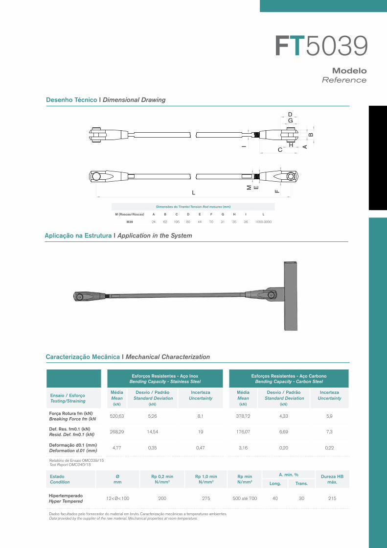
Desenho Técnico I Dimensional Drawing
Caracterização Mecânica I Mechanical Characterization
ModeloReference
Aplicação na estrutura I Application in the system
FT5006
L
M E
F
I
C AB
DG
H
Dimensões do Tirante/Tension Rod mesures (mm)
M (Roscas/Roscas) A B C D E F G H I L
M6 5 13 47 20 10 16 6 10 4 1000-3000
Esforços Resistentes - Aço Inox Bending Capacity - Stainless Steel
Esforços Resistentes - Aço Carbono Bending Capacity - Carbon Steel
Ensaio / Esforço Testing/Straining
Média Mean(kN)
Desvio / Padrão Standard Deviation
(kN)
IncertezaUncertainty
Média Mean(kN)
Desvio / Padrão Standard Deviation
(kN)
IncertezaUncertainty
Força Rotura fm (kN) Breaking Force fm (kN
15,51 0,19 0,25 10,94 1,09 1,60
Def. Res. fm0.1 (kN)Resid. Def. fm0.1 (kN)
9,29 0,33 0,36 6,33 0,47 0,51
Deformação d0.1 (mm) Deformation d.01 (mm)
1,33 0,07 0,078 0,92 0,13 0,14
Estado Condition
Ø mm
Rp 0,2 min N/mm2
Rp 1,0 min N/mm2
Rp min N/mm2
A. min. % Dureza HB máx.Long. Trans.
Hipertemperado Hyper Tempered
12<Ø<100 200 275 500 até 700 40 30 215
Dados facultados pelo fornecedor do material em bruto. Caracterização mecânicas a temperaturas ambientes.Data provided by the supplier of the raw material. Mechanical properties at room temperature.
Test Report OMC040/15Relatório de Ensaio OMC039/15

Componentes I Components:Sugestão de Montagem
Suggested Mounting
TENSION RODTIRANTES
ModeloReference
1. Montar peça nº 3 ao estrutural e de seguida colocar veio nº 2 e peça nº 1 para sua fixação;
Assemble part No. 3 into main structure then put come n. 2 and part no. 1 to its mounting;
2. Rodar a peça nº 4 para tensionar o tirante apertando por fim a fêmea nº 5;
Rotate the part No 4 to tension the rod pressing for an end to Nut no. 5;
3. Após montagem verificar apertos. After, check mounting grips.
Características I Caracteristic
Código I Code:FT5010
Peso I Weight: 0,200 - 2,000 (kg)
Medida I Measure:40 x 40 x 1000 - 3000 (mm)
Tension rod M10 lenght 1000 - 3000 mmTirante M10 comprimento 1000 - 3000 mm
FT5010
Nº No.
Qt. Qt.
Designação Designation
Material Material
1 2 Anilha de aperto / Washer grip Aisi 316
2 2 Veio de fixação / Clamping axle Aisi 316
3 2 Forquilha / Fork Aisi 316
4 1 Tirante M10 / Axle thread M10 Aisi 316
5 2 Contra - Fêmea / Nut clamping Aisi 316
6 2 Parafuso para pino / Screw for pin Aisi 316
1 2 3 4 5 6

Desenho Técnico I Dimensional Drawing
Caracterização Mecânica I Mechanical Characterization
ModeloReference
FT5010
L
M E
F
I
C AB
DG
H
Aplicação na estrutura I Application in the system
Dimensões do Tirante/Tension Rod mesures (mm)
M (Roscas/Roscas) A B C D E F G H I L
M10 6 18 72 30 13,5 22 8 12 8 1000-3000
Esforços Resistentes - Aço Inox Bending Capacity - Stainless Steel
Esforços Resistentes - Aço Carbono Bending Capacity - Carbon Steel
Ensaio / Esforço Testing/Straining
Média Mean(kN)
Desvio / Padrão Standard Deviation
(kN)
IncertezaUncertainty
Média Mean(kN)
Desvio / Padrão Standard Deviation
(kN)
IncertezaUncertainty
Força Rotura fm (kN) Breaking Force fm (kN
42,79 1,95 2,1 31,13 0,26 0,43
Def. Res. fm0.1 (kN)Resid. Def. fm0.1 (kN)
22,11 1,71 1,9 24,24 0,43 0,50
Deformação d0.1 (mm) Deformation d.01 (mm)
1,31 0,29 0,31 1,40 0,09 0,099
Estado Condition
Ø mm
Rp 0,2 min N/mm2
Rp 1,0 min N/mm2
Rp min N/mm2
A. min. % Dureza HB máx.Long. Trans.
Hipertemperado Hyper Tempered
12<Ø<100 200 275 500 até 700 40 30 215
Dados facultados pelo fornecedor do material em bruto. Caracterização mecânicas a temperaturas ambientes.Data provided by the supplier of the raw material. Mechanical properties at room temperature.
Test Report OMC040/15Relatório de Ensaio OMC039/15

Componentes I Components:Sugestão de Montagem
Suggested Mounting
TENSION RODTIRANTES
ModeloReference
1. Montar peça nº 3 ao estrutural e de seguida colocar veio nº 2 e peça nº 1 para sua fixação;
Assemble part No. 3 into main structure then put come n. 2 and part no. 1 to its mounting;
2. Rodar a peça nº 4 para tensionar o tirante apertando por fim a fêmea nº 5;
Rotate the part No 4 to tension the rod pressing for an end to Nut no. 5.
3. Após montagem verificar apertos.
After, check mounting grips.
Características I Caracteristic
Código I Code:FT5012
Peso I Weight: 0,300 - 2,500 (kg)
Medida I Measure:40 x 40 x 1000 - 3000 (mm)
Tension rod M12, lenght 1000 - 3000 mmTirante M12 comprimento 1000 - 3000 mm
FT5012
Nº No.
Qt. Qt.
Designação Designation
Material Material
1 2 Anilha de aperto / Washer grip Aisi 316
2 2 Veio de fixação / Clamping axle Aisi 316
3 2 Forquilha / Fork Aisi 316
4 1 Tirante M12 / Axle thread M12 Aisi 316
5 2 Contra - Fêmea / Nut clamping Aisi 316
6 2 Parafuso para pino / Screw for pin Aisi 316
1 2 3 4 5 6

Desenho Técnico I Dimensional Drawing
Aplicação na Estrutura I Application in the System
Caracterização Mecânica I Mechanical Characterization
ModeloReference
FT5012
L
M E
F
I
C AB
DG
H
Dimensões do Tirante/Tension Rod mesures (mm)
M (Roscas/Roscas) A B C D E F G H I L
M12 10 23 92 39 16 28 12 16 10 1000-3000
Esforços Resistentes - Aço Inox Bending Capacity - Stainless Steel
Esforços Resistentes - Aço Carbono Bending Capacity - Carbon Steel
Ensaio / Esforço Testing/Straining
Média Mean(kN)
Desvio / Padrão Standard Deviation
(kN)
IncertezaUncertainty
Média Mean(kN)
Desvio / Padrão Standard Deviation
(kN)
IncertezaUncertainty
Força Rotura fm (kN) Breaking Force fm (kN
77,47 2,44 2,68 58,31 0,50 0,87
Def. Res. fm0.1 (kN)Resid. Def. fm0.1 (kN)
55,73 4,88 5,43 38,72 2,27 2,50
Deformação d0.1 (mm) Deformation d.01 (mm)
2,37 0,35 0,37 1,69 0,18 0,19
Estado Condition
Ø mm
Rp 0,2 min N/mm2
Rp 1,0 min N/mm2
Rp min N/mm2
A. min. % Dureza HB máx.Long. Trans.
Hipertemperado Hyper Tempered
12<Ø<100 200 275 500 até 700 40 30 215
Dados facultados pelo fornecedor do material em bruto. Caracterização mecânicas a temperaturas ambientes.Data provided by the supplier of the raw material. Mechanical properties at room temperature.
Test Report OMC040/15Relatório de Ensaio OMC039/15

Componentes I Components:Sugestão de Montagem
Suggested Mounting
TENSION RODTIRANTES
ModeloReference
1. Montar peça nº 3 ao estrutural e de seguida colocar veio nº 2 e peça nº 1 para sua fixação;
Assemble part No. 3 into main structure then put come n. 2 and part no. 1 to its mounting;
2. Rodar a peça nº 4 para tensionar o tirante apertando por fim a fêmea nº 5;
Rotate the part No 4 to tension the rod pressing for an end to Nut no. 5;
3. Após montagem verificar apertos.
After, check mounting grips.
Características I Caracteristic
Código I Code:FT5016
Peso I Weight: 0,400 - 3,000 (kg)
Medida I Measure:40 x 40 x 1000 - 3000 (mm)
Tension rod M16 lenght 1000 - 3000 mmTirante M16 comprimento 1000 - 3000 mm
FT5016
Nº No.
Qt. Qt.
Designação Designation
Material Material
1 2 Anilha de aperto / Washer grip Aisi 316
2 2 Veio de fixação / Clamping axle Aisi 316
3 2 Forquilha / Fork Aisi 316
4 1 Tirante M16 / Axle thread M16 Aisi 316
5 2 Contra - Fêmea / Nut clamping Aisi 316
6 2 Parafuso para pino / Screw for pin Aisi 316
1 2 3 4 5 6

Desenho Técnico I Dimensional Drawing
Aplicação na Estrutura I Application in the System
Caracterização Mecânica I Mechanical Characterization
ModeloReference
FT5016
L
M E
F
I
C AB
DG
H
Dimensões do Tirante/Tension Rod mesures (mm)
M (Roscas/Roscas) A B C D E F G H I L
M16 12 30 120 50 20 35 16 20 14 1000-3000
Esforços Resistentes - Aço Inox Bending Capacity - Stainless Steel
Esforços Resistentes - Aço Carbono Bending Capacity - Carbon Steel
Ensaio / Esforço Testing/Straining
Média Mean(kN)
Desvio / Padrão Standard Deviation
(kN)
IncertezaUncertainty
Média Mean(kN)
Desvio / Padrão Standard Deviation
(kN)
IncertezaUncertainty
Força Rotura fm (kN) Breaking Force fm (kN
112,16 2,94 3,25 85,47 0,74 1,32
Def. Res. fm0.1 (kN)Resid. Def. fm0.1 (kN)
89,36 8,05 8,95 53,2 4,11 4,50
Deformação d0.1 (mm) Deformation d.01 (mm)
3,43 0,40 0,44 1,98 0,27 0,28
Estado Condition
Ø mm
Rp 0,2 min N/mm2
Rp 1,0 min N/mm2
Rp min N/mm2
A. min. % Dureza HB máx.Long. Trans.
Hipertemperado Hyper Tempered
12<Ø<100 200 275 500 até 700 40 30 215
Dados facultados pelo fornecedor do material em bruto. Caracterização mecânicas a temperaturas ambientes.Data provided by the supplier of the raw material. Mechanical properties at room temperature.
Test Report OMC040/15Relatório de Ensaio OMC039/15

Componentes I Components:Sugestão de Montagem
Suggested Mounting
TENSION RODTIRANTES
ModeloReference
Características I Caracteristic
Código I Code:FT5020
Peso I Weight: 2,00 - 5,500 (kg)
Medida I Measure:40 x 40 x 1000 - 3000 (mm)
Tension rod M20 lenght 1000 - 3000 mmTirante M20 comprimento 1000 - 3000 mm
FT5020
Nº No.
Qt. Qt.
Designação Designation
Material Material
1 2 Anilha de aperto / Washer grip Aisi 316
2 2 Veio de fixação / Clamping axle Aisi 316
3 2 Forquilha / Fork Aisi 316
4 1 Tirante M20 / Axle thread M20 Aisi 316
5 2 Contra - Fêmea / Nut clamping Aisi 316
6 2 Parafuso para pino / Screw for pin Aisi 316
1. Montar peça nº 3 ao estrutural e de seguida colocar veio nº 2 e peça nº 1 para sua fixação;
Assemble part No. 3 into main structure then put come n. 2 and part no. 1 to its mounting;
2. Rodar a peça nº 4 para tensionar o tirante apertando por fim a fêmea nº 5;
Rotate the part No 4 to tension the rod pressing for an end to Nut no. 5;
3. Após montagem verificar apertos.
After, check mounting grips.
1 2 3 4 5 6

Desenho Técnico I Dimensional Drawing
Aplicação na Estrutura I Application in the System
Caracterização Mecânica I Mechanical Characterization
ModeloReference
FT5020
L
M E
F
I
C AB
DG
H
Dimensões do Tirante/Tension Rod mesures (mm)
M (Roscas/Roscas) A B C D E F G H I L
M20 16 38 145 60 24 45 19 24 18 1000-3000
Esforços Resistentes - Aço Inox Bending Capacity - Stainless Steel
Esforços Resistentes - Aço Carbono Bending Capacity - Carbon Steel
Ensaio / Esforço Testing/Straining
Média Mean(kN)
Desvio / Padrão Standard Deviation
(kN)
IncertezaUncertainty
Média Mean(kN)
Desvio / Padrão Standard Deviation
(kN)
IncertezaUncertainty
Força Rotura fm (kN) Breaking Force fm (kN
197,59 3,92 4,4 161,93 1,22 2,2
Def. Res. fm0.1 (kN)Resid. Def. fm0.1 (kN)
145,25 14,39 16 83,79 7,78 8,50
Deformação d0.1 (mm) Deformation d.01 (mm)
4,09 0,51 0,56 2,69 0,44 0,47
Estado Condition
Ø mm
Rp 0,2 min N/mm2
Rp 1,0 min N/mm2
Rp min N/mm2
A. min. % Dureza HB máx.Long. Trans.
Hipertemperado Hyper Tempered
12<Ø<100 200 275 500 até 700 40 30 215
Dados facultados pelo fornecedor do material em bruto. Caracterização mecânicas a temperaturas ambientes.Data provided by the supplier of the raw material. Mechanical properties at room temperature.
Test Report OMC040/15Relatório de Ensaio OMC039/15

Componentes I Components:Sugestão de Montagem
Suggested Mounting
TENSION RODTIRANTES
ModeloReference
Características I Caracteristic
Código I Code:FT5024
Peso I Weight: 3,00-6,00 (Kg)
Medida I Measure:40 x 40 x 1000 - 3000 (mm)
Tension rod M24 lenght 1000 - 3000 mmTirante M24 comprimento 1000 - 3000 mm
FT5024
Nº No.
Qt. Qt.
Designação Designation
Material Material
1 2 Anilha de aperto / Washer grip Aisi 316
2 2 Veio de fixação / Clamping axle Aisi 316
3 2 Forquilha / Fork Aisi 316
4 1 Tirante M24 / Axle thread M24 Aisi 316
5 2 Contra - Fêmea / Nut clamping Aisi 316
6 2 Parafuso para pino / Screw for pin Aisi 316
1. Montar peça nº 3 ao estrutural e de seguida colocar veio nº 2 e peça nº 1 para sua fixação;
Assemble part No. 3 into main structure then put come n. 2 and part no. 1 to its mounting;
2. Rodar a peça nº 4 para tensionar o tirante apertando por fim a fêmea nº 5;
Rotate the part No 4 to tension the rod pressing for an end to Nut no. 5;
3. Após montagem verificar apertos.
After, check mounting grips.
1 2 3 4 5 6

Desenho Técnico I Dimensional Drawing
Aplicação na Estrutura I Application in the System
Caracterização Mecânica I Mechanical Characterization
ModeloReference
FT5024
L
M E
F
I
C AB
DG
H
Dimensões do Tirante/Tension Rod mesures (mm)
M (Roscas/Roscas) A B C D E F G H I L
M24 16 45 158 65 29 55 22 28 20 1000-3000
Esforços Resistentes - Aço Inox Bending Capacity - Stainless Steel
Esforços Resistentes - Aço Carbono Bending Capacity - Carbon Steel
Ensaio / Esforço Testing/Straining
Média Mean(kN)
Desvio / Padrão Standard Deviation
(kN)
IncertezaUncertainty
Média Mean(kN)
Desvio / Padrão Standard Deviation
(kN)
IncertezaUncertainty
Força Rotura fm (kN) Breaking Force fm (kN
286,43 3,78 4,8 155,82 2,35 2,9
Def. Res. fm0.1 (kN)Resid. Def. fm0.1 (kN)
138,46 5,08 5,6 103,14 0,91 1,4
Deformação d0.1 (mm) Deformation d.01 (mm)
3,36 0,29 0,32 2,66 0,16 0,18
Estado Condition
Ø mm
Rp 0,2 min N/mm2
Rp 1,0 min N/mm2
Rp min N/mm2
A. min. % Dureza HB máx.Long. Trans.
Hipertemperado Hyper Tempered
12<Ø<100 200 275 500 até 700 40 30 215
Dados facultados pelo fornecedor do material em bruto. Caracterização mecânicas a temperaturas ambientes.Data provided by the supplier of the raw material. Mechanical properties at room temperature.
Test Report OMC040/15Relatório de Ensaio OMC039/15

Componentes I Components:Sugestão de Montagem
Suggested Mounting
TENSION RODTIRANTES
ModeloReference
Características I Caracteristic
Código I Code:FT5030
Peso I Weight: 3,50-6,50 (Kg)
Medida I Measure:40 x 40 x 1000 - 3000 (mm)
Tension rod M30 lenght 1000 - 3000 mmTirante M30 comprimento 1000 - 3000 mm
FT5030
Nº No.
Qt. Qt.
Designação Designation
Material Material
1 2 Anilha de aperto / Washer grip Aisi 316
2 2 Veio de fixação / Clamping axle Aisi 316
3 2 Forquilha / Fork Aisi 316
4 1 Tirante M30 / Axle thread M30 Aisi 316
5 2 Contra - Fêmea / Nut clamping Aisi 316
6 2 Parafuso para pino / Screw for pin Aisi 316
1. Montar peça nº 3 ao estrutural e de seguida colocar veio nº 2 e peça nº 1 para sua fixação;
Assemble part No. 3 into main structure then put come n. 2 and part no. 1 to its mounting;
2. Rodar a peça nº 4 para tensionar o tirante apertando por fim a fêmea nº 5;
Rotate the part No 4 to tension the rod pressing for an end to Nut no. 5;
3. Após montagem verificar apertos.
After, check mounting grips.
1 2 3 4 5 6

Desenho Técnico I Dimensional Drawing
Aplicação na Estrutura I Application in the System
Caracterização Mecânica I Mechanical Characterization
ModeloReference
FT5030
L
M E
F
I
C AB
DG
H
Dimensões do Tirante/Tension Rod mesures (mm)
M (Roscas/Roscas) A B C D E F G H I L
M30 20 54 187 77,5 34,5 60 25 30 24 1000-3000
Esforços Resistentes - Aço Inox Bending Capacity - Stainless Steel
Esforços Resistentes - Aço Carbono Bending Capacity - Carbon Steel
Ensaio / Esforço Testing/Straining
Média Mean(kN)
Desvio / Padrão Standard Deviation
(kN)
IncertezaUncertainty
Média Mean(kN)
Desvio / Padrão Standard Deviation
(kN)
IncertezaUncertainty
Força Rotura fm (kN) Breaking Force fm (kN
403,94 5,45 6,9 257,44 3,92 4,7
Def. Res. fm0.1 (kN)Resid. Def. fm0.1 (kN)
286,91 6,45 7,2 135,85 5,28 5,8
Deformação d0.1 (mm) Deformation d.01 (mm)
5,40 0,35 0,39 3,13 0,40 0,44
Estado Condition
Ø mm
Rp 0,2 min N/mm2
Rp 1,0 min N/mm2
Rp min N/mm2
A. min. % Dureza HB máx.Long. Trans.
Hipertemperado Hyper Tempered
12<Ø<100 200 275 500 até 700 40 30 215
Dados facultados pelo fornecedor do material em bruto. Caracterização mecânicas a temperaturas ambientes.Data provided by the supplier of the raw material. Mechanical properties at room temperature.
Test Report OMC040/15Relatório de Ensaio OMC039/15

Componentes I Components:Sugestão de Montagem
Suggested Mounting
TENSION RODTIRANTES
ModeloReference
Características I Caracteristic
Código I Code:FT5039
Peso I Weight: 4,00-7,00 (Kg)
Medida I Measure:40 x 40 x 1000 - 3000 (mm)
Tension rod M39 lenght 1000 - 3000 mmTirante M39 comprimento 1000 - 3000 mm
FT5039
Nº No.
Qt. Qt.
Designação Designation
Material Material
1 2 Anilha de aperto / Washer grip Aisi 316
2 2 Veio de fixação / Clamping axle Aisi 316
3 2 Forquilha / Fork Aisi 316
4 1 Tirante M39 / Axle thread M39 Aisi 316
5 2 Contra - Fêmea / Nut clamping Aisi 316
6 2 Parafuso para pino / Screw for pin Aisi 316
1. Montar peça nº 3 ao estrutural e de seguida colocar veio nº 2 e peça nº 1 para sua fixação;
Assemble part No. 3 into main structure then put come n. 2 and part no. 1 to its mounting;
2. Rodar a peça nº 4 para tensionar o tirante apertando por fim a fêmea nº 5;
Rotate the part No 4 to tension the rod pressing for an end to Nut no. 5;
3. Após montagem verificar apertos.
After, check mounting grips.
1 2 3 4 5 6
Desenho Técnico I Dimensional Drawing
Aplicação na Estrutura I Application in the System
Caracterização Mecânica I Mechanical Characterization
ModeloReference
FT5039
L
M E
F
I
C AB
DG
H
Dimensões do Tirante/Tension Rod mesures (mm)
M (Roscas/Roscas) A B C D E F G H I L
M39 24 62 195 80 44 70 31 35 36 1000-3000
Esforços Resistentes - Aço Inox Bending Capacity - Stainless Steel
Esforços Resistentes - Aço Carbono Bending Capacity - Carbon Steel
Ensaio / Esforço Testing/Straining
Média Mean(kN)
Desvio / Padrão Standard Deviation
(kN)
IncertezaUncertainty
Média Mean(kN)
Desvio / Padrão Standard Deviation
(kN)
IncertezaUncertainty
Força Rotura fm (kN) Breaking Force fm (kN
520,63 5,26 8,1 378,72 4,33 5,9
Def. Res. fm0.1 (kN)Resid. Def. fm0.1 (kN)
268,29 14,54 19 176,07 6,69 7,3
Deformação d0.1 (mm) Deformation d.01 (mm)
4,77 0,35 0,47 3,16 0,20 0,22
Estado Condition
Ø mm
Rp 0,2 min N/mm2
Rp 1,0 min N/mm2
Rp min N/mm2
A. min. % Dureza HB máx.Long. Trans.
Hipertemperado Hyper Tempered
12<Ø<100 200 275 500 até 700 40 30 215
Dados facultados pelo fornecedor do material em bruto. Caracterização mecânicas a temperaturas ambientes.Data provided by the supplier of the raw material. Mechanical properties at room temperature.
Test Report OMC040/15Relatório de Ensaio OMC039/15
Componentes I Components:Sugestão de Montagem
Suggested Mounting
TENSION RODTIRANTES
ModeloReference
Características I Caracteristic
Código I Code:FT5555
Peso I Weight: Variável (Kg)
Medida I Measure:40 x 40 x 1000 - 3000 (mm)
Tension rod M_ lenght by measureTirante M_ comprimento por medida
FT5555
Nº No.
Qt. Qt.
Designação Designation
Material Material
1 2 Anilha de aperto / Washer grip Aisi 316
2 2 Veio de fixação / Clamping axle Aisi 316
3 2 Forquilha / Fork Aisi 316
4 1 Tirante M_ / Axle thread M_ Aisi 316
5 2 Contra - Fêmea / Nut clamping Aisi 316
6 2 Parafuso para pino / Screw for pin Aisi 316
1. Montar peça nº 3 ao estrutural e de seguida colocar veio nº 2 e peça nº 1 para sua fixação;
Assemble part No. 3 into main structure then put come n. 2 and part no. 1 to its mounting;
2. Rodar a peça nº 4 para tensionar o tirante apertando por fim a fêmea nº 5;
Rotate the part No 4 to tension the rod pressing for an end to Nut no. 5;
3. Após montagem verificar apertos.
After, check mounting grips.
1 2 3 4 5 6

Desenho Técnico I Dimensional Drawing
Aplicação na Estrutura I Application in the System
Caracterização Mecânica I Mechanical Characterization
ModeloReference
FT5555
L
M E
F
I
C AB
DG
H
Dimensões do Tirante/Tension Rod mesures (mm)
M (Roscas/Roscas) A B C D E F G L
M_ Conforme a necessidade do cliente
Estado Condition
Ø mm
Rp 0,2 min N/mm2
Rp 1,0 min N/mm2
Rp min N/mm2
A. min. % Dureza HB máx.Long. Trans.
Hipertemperado Hyper Tempered
12<Ø<100 200 275 500 até 700 40 30 215
Dados facultados pelo fornecedor do material em bruto. Caracterização mecânicas a temperaturas ambientes.Data provided by the supplier of the raw material. Mechanical properties at room temperature.

Componentes I Components:
TENSION RODTIRANTES
ModeloReference
Sugestão de Montagem
Suggested Mounting
Código I Code:FT5116
Peso I Weight: 5,880 - 23,500 (kg)
Medida I Measure:55x55x1000-3000 (mm)
Características I Caracteristic
Tirante M16 comprimento 1000 - 3000 mm corpo em tuboTension rod M16, lenght 1000 - 3000 mm in tube
FT5116
1. Montar peça nº 3 ao estrutural e de seguida colocar veio nº 2 e peça nº 1 para sua fixação;
Assemble part No. 3 into main structure then put come n. 2 and part no. 1 to its mounting;
2. Rodar a peça nº 4 para tensionar o tirante apertando por fim a fêmea n.º 5;
Rotate the part No 4 to tension the rod pressing for an end to Nut no. 5;
3. Após montagem verificar apertos.
After, check mounting grips.
Nº No.
Qt. Qt.
Designação Designation
Material Material
1 2 Parafuso para pino / Screw for pin Aisi 316
2 2 Veio de fixação / Clamping axle Aisi 316
3 2 Forquilha M16 / Fork M16 Aisi 316
4 1 Tirante em tubo / Rod in tube Aisi 316
5 2 Contra - Fêmea M16 / Nut Clamping M16 Aisi 316
6 2 Veio roscado M16 dta/esq. / Axle thread M16 R/L Aisi 316
7 2 Anilha de aperto / Washer grip Aisi 316
1 2 3 4 5 6 7

Desenho Técnico I Dimensional Drawing
Aplicação na Estrutura I Application in the System
Caracterização Mecânica I Mechanical Characterization
ModeloReference
FT5116
L
M E
F
I
C AB
DG
H
Dimensões do Tirante/Tension Rod mesures (mm)
M (Roscas/Roscas) A B C D E F L
M16 16 30 98 16 23 27 1000-3000
Estado Condition
Ø mm
Rp 0,2 min N/mm2
Rp 1,0 min N/mm2
Rp min N/mm2
A. min. % Dureza HB máx.Long. Trans.
Hipertemperado Hyper Tempered
12<Ø<100 200 275 500 até 700 40 30 215
Dados facultados pelo fornecedor do material em bruto. Caracterização mecânicas a temperaturas ambientes.Data provided by the supplier of the raw material. Mechanical properties at room temperature.

abr.2
016|
V02
FA
I FT
Silva e Ventura, lda.Zona Industrial de Irijó - Lote 5 e 6
3740-176 Rocas do VougaPORTUGAL
Tel.: (+351) 234 558 737 /484Fax: (+351) 234 558 483
www.s-vitech.com
ITeCons