Embed Size (px)
Citation preview

1 Automação Industrial
© Lino Marques 2015
Motores Eléctricos
Lino Marques
Versão de 21/04/2015

2 Automação Industrial
© Lino Marques 2015
Conteúdo
• Introdução • Principais tipos de motores
• Motores DC com escovas • Motores de indução • Motores DC sem escovas • Motores de passo
• Comando e controlo • Variadores e contactores • Servomotores
• Eixos motorizados e controlo motriz • Máquinas de CNC e células flexíveis de fabrico

3 Automação Industrial
© Lino Marques 2015
Referências
• Motors and Drives - A Practical Technology Guide (ISA 2003)
• Electric Motor Controls, Ninth Edition (Delmar 2010) • Electric Motors and Drives - Fundamentals, Types, and
Applications, 3rd Ed (Elsevier 2006)
4 Automação Industrial Motores Eléctricos
© Lino Marques 2015
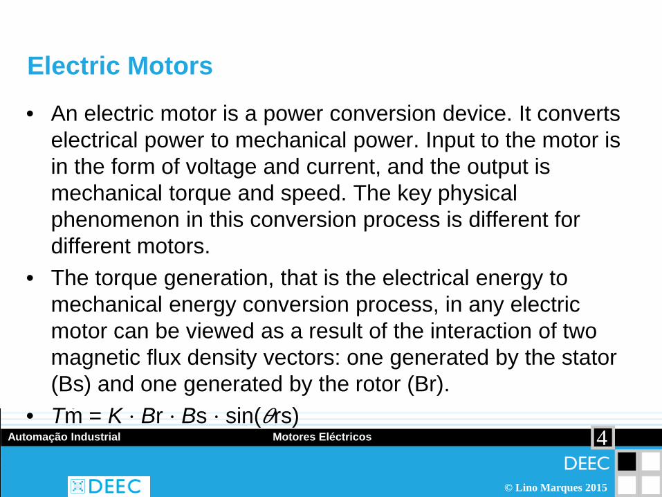
Electric Motors
• An electric motor is a power conversion device. It converts electrical power to mechanical power. Input to the motor is in the form of voltage and current, and the output is mechanical torque and speed. The key physical phenomenon in this conversion process is different for different motors.
• The torque generation, that is the electrical energy to mechanical energy conversion process, in any electric motor can be viewed as a result of the interaction of two magnetic flux density vectors: one generated by the stator (Bs) and one generated by the rotor (Br).
• Tm = K ⋅ Br ⋅ Bs ⋅ sin(𝜃𝜃rs)

5 Automação Industrial Motores Eléctricos
© Lino Marques 2015
Force production

6 Automação Industrial Motores Eléctricos
© Lino Marques 2015
Motoring and braking operation
7 Automação Industrial Motores Eléctricos
© Lino Marques 2015
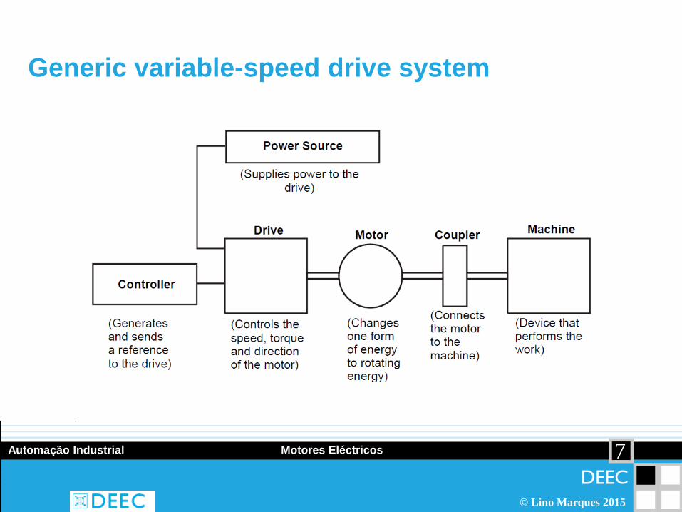
Generic variable-speed drive system

8 Automação Industrial Motores Eléctricos
© Lino Marques 2015
Power density of electrical machines

9 Automação Industrial Motores Eléctricos
© Lino Marques 2015
Motores DC com escovas
• In the case of DC motors, there are two magnetic fields. In brush-type DC motors, one of the magnetic fields is due to the current through the armature winding on the rotor, and the other magnetic field is due to the permanent magnets in the stator (or due to field excitation of the stator winding if electromagnets are used instead of permanent magnets). In the case of brushless DC motors, the roles of rotor and stator are swapped.

10 Automação Industrial Motores Eléctricos
© Lino Marques 2015
DC motor operating principles

11 Automação Industrial Motores Eléctricos
© Lino Marques 2015

12 Automação Industrial Motores Eléctricos
© Lino Marques 2015
Torque as a function of the angular position of the rotor

13 Automação Industrial Motores Eléctricos
© Lino Marques 2015
Components of a brush-type DC motor

14 Automação Industrial Motores Eléctricos
© Lino Marques 2015
Cross-section of a DC Motor
http://kbreee.blogspot.pt/2013/11/magnetization-curve-of-dc-generator.html

15 Automação Industrial Motores Eléctricos
© Lino Marques 2015
Permanent magnet DC motor and curve

16 Automação Industrial Motores Eléctricos
© Lino Marques 2015
Series wound DC motor circuit and curve

17 Automação Industrial Motores Eléctricos
© Lino Marques 2015
Shunt wound DC motor and curve

18 Automação Industrial Motores Eléctricos
© Lino Marques 2015
Speed-controlled d.c. motor drive

19 Automação Industrial Motores Eléctricos
© Lino Marques 2015
Motores de indução
• In the case of AC motors, the first magnetic field is setup by the excitation current on the stator. This magnetic field in turn induces a voltage in the rotor conductors by Faraday’s induction principle. The induced voltage at the rotor conductors results in current which in turn sets up its own magnetic field, which is the second magnetic field. The torque is produced by the interaction of the two magnetic fields.

20 Automação Industrial Motores Eléctricos
© Lino Marques 2015
Induction motor elements
http://machinedesign.com/motorsdrives/difference-between-ac-induction-permanent-magnet-and-servomotor-technologies

21 Automação Industrial Motores Eléctricos
© Lino Marques 2015
Squirrel cage rotor

22 Automação Industrial Motores Eléctricos
© Lino Marques 2015
Flux rotation
Current is induced in the rotor’s conducting bars, and associated magnetic fields interact with those of the stator. This causes the rotor to follow the field generated by the stator, to rotate the output shaft.

23 Automação Industrial Motores Eléctricos
© Lino Marques 2015
Stator windings of an AC induction motor
(a) two-pole (P = 2) configuration, (b) four-pole (P = 4) configuration, (c) six-pole (P = 6) configuration.

24 Automação Industrial Motores Eléctricos
© Lino Marques 2015
Typical torque–speed curves

25 Automação Industrial Motores Eléctricos
© Lino Marques 2015
Speed control of cage motor by stator voltage variation
(a) low-resistance rotor, (b) high-resistance rotor

26 Automação Industrial Motores Eléctricos
© Lino Marques 2015
Torque-speed performance in steady-state under various control methods

27 Automação Industrial Motores Eléctricos
© Lino Marques 2015
Arranque de motores de indução
• Directo • Estrela-triângulo • Soft-starter • Variador electrónico de velocidade

28 Automação Industrial Motores Eléctricos
© Lino Marques 2015
Esquema de arranque directo com arrancador motor e contactor

29 Automação Industrial Motores Eléctricos
© Lino Marques 2015
Motor torque and inrush current (line starting)

30 Automação Industrial Motores Eléctricos
© Lino Marques 2015
Arranque directo: características e aplicações
• Binário inicial de arranque: 0,6 a 1,5 Mn. • Corrente inicial de arranque: 4 a 8 In. • Duração média do arranque: 2 a 3 s. Aplicações: • Motores até 4kW. • Máquinas pequenas que possam arrancar a plena carga,
sem problemas mecânicos: Rolamentos, correias, etc. • Bombas, Ventiladores.

31 Automação Industrial Motores Eléctricos
© Lino Marques 2015
Vantagens e inconvenientes
• Arrancador de esquema simples.
• Custo reduzido. • Binário de arranque elevado
comparativamente a outros arranques com contactores.
• Pico de intensidade muito elevado (a rede deve suportar este pico).
• Arranque brusco, golpe mecânico.
• Risco de roturas
• Maior desgaste dos rolamentos, transmissões a correias ou correntes.

32 Automação Industrial Motores Eléctricos
© Lino Marques 2015
Reducing the starting current Primary Resistor or Reactance • Uses series reactance or resistance to reduce the current during the first
seconds. After a preset time interval, the motor is connected directly across the line.
Auto Transformer • Uses an auto transformer to directly reduce voltage and the current for the
first few seconds. After a preset time interval, the motor is connected directly across the line.
Wye–Delta • Applies the voltage across the Y connection to reduce the current during the
first few seconds. After a preset time interval, the motor is connected in delta mode permitting full current.
Part–Winding • Uses a motor design that has two separate winding circuits. Upon starting,
only one winding circuit is engaged and current is reduced. After a preset time interval, the full winding of the motor is connected directly across the line.

33 Automação Industrial Motores Eléctricos
© Lino Marques 2015
Arranque estrela-triângulo

34 Automação Industrial Motores Eléctricos
© Lino Marques 2015
Arranque estrela-triângulo
Estrela: KM2, KM1 Triângulo: KM2, KM3

35 Automação Industrial Motores Eléctricos
© Lino Marques 2015
Curvas
Intensidade em triângulo
Intensidade em estrela
Binário em triângulo
Binário em estrela

36 Automação Industrial Motores Eléctricos
© Lino Marques 2015
Características e aplicações
• Binário inicial de arranque: 0,2 a 0,5 Mn • Corrente inicial de arranque: 1,3 a 2,6 In • Duração média do arranque: 3 a 7 s Aplicações : • Máquinas de arranque em vazio:
Ventiladores e bombas centrífugas de potência reduzida. • Máquinas-ferramenta. • Máquinas para madeira, etc..

37 Automação Industrial Motores Eléctricos
© Lino Marques 2015
Vantagens e inconvenientes
• Arrancador relativamente económico
• Boa relação binário/intensidade • Redução da corrente de
arranque
• Binário de arranque reduzido • Corte da alimentação durante a
transição (transitórios) • Ligação ao motor a 6 cabos • Sem possibilidade de regulação

38 Automação Industrial Motores Eléctricos
© Lino Marques 2015
Current regulation in AC motor phases by a field oriented vector control (FOVC) drive

39 Automação Industrial Motores Eléctricos
© Lino Marques 2015
Motores DC sem escovas
40 Automação Industrial Motores Eléctricos
© Lino Marques 2015
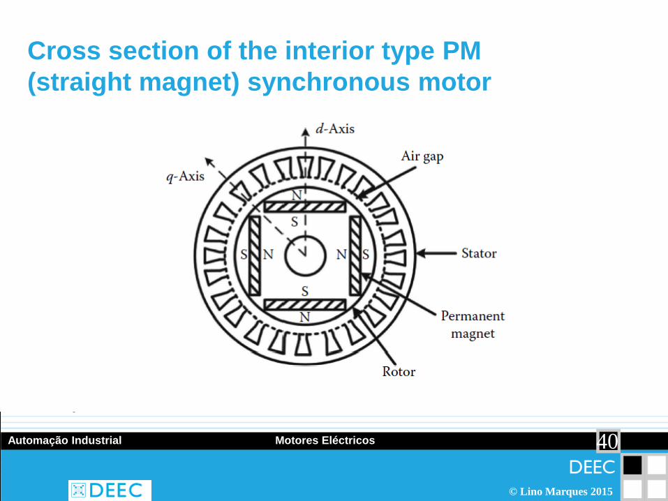
Cross section of the interior type PM (straight magnet) synchronous motor

41 Automação Industrial Motores Eléctricos
© Lino Marques 2015
Cross section of the surface-mounted type PM synchronous motor

42 Automação Industrial Motores Eléctricos
© Lino Marques 2015
Cross section of the inset type PM synchronous motor

43 Automação Industrial Motores Eléctricos
© Lino Marques 2015
Rotor cross section of the 4-pole (V-shaped) IPM motor

44 Automação Industrial Motores Eléctricos
© Lino Marques 2015
Permanent Magnetic Materials • Alnico which is an aluminum (Al)-nickel (Ni)-cobalt (Co) (“AlNiCo”)
mixture. • Ceramic (hard ferrite) magnetic materials which consists of strontium,
barium ferritite mixtures. • Samarium cobalt (samarium and cobalt mixtures, SmCo5,
Sm2Co17). • Neodymium (neodymium, iron, and boron are the main mixture
components with small amounts of other compounds). The ideal mixture is Nd2Fe14B1.

45 Automação Industrial Motores Eléctricos
© Lino Marques 2015
Evolution of PM materials

46 Automação Industrial Motores Eléctricos
© Lino Marques 2015
Performance Comparison of IPM and Induction Motors

47 Automação Industrial Motores Eléctricos
© Lino Marques 2015
Stepper vs. Brushless

48 Automação Industrial Motores Eléctricos
© Lino Marques 2015
Linear motors

49 Automação Industrial Motores Eléctricos
© Lino Marques 2015
Linear motors

50 Automação Industrial Motores Eléctricos
© Lino Marques 2015
Linear motor elements

51 Automação Industrial Motores Eléctricos
© Lino Marques 2015

52 Automação Industrial Motores Eléctricos
© Lino Marques 2015
Motores de Passo
53 Automação Industrial Motores Eléctricos
© Lino Marques 2015
Motores de passo
• Stepper motors (permanent magnet (PM) type) work on basically the same principle as brushless DC motors, except that the stator winding distribution is different. A given stator excitation state defines a stable rotor position as a result of the attraction between electromagnetic poles of the stator and permanent magnets of the rotor. The rotor moves to minimize the magnetic reluctance. At a stable rotor position of a step motor, two magnetic fields are parallel.

54 Automação Industrial Motores Eléctricos
© Lino Marques 2015
Características
• Brushless – Stepper motors are brushless. The commutator and brushes of conventional motors are some of the most failure-prone components, and they create electrical arcs that are undesirable or dangerous in some environments.
• Load Independent – Stepper motors will turn at a set speed regardless of load as long as the load does not exceed the torque rating for the motor.
• Open Loop Positioning – Stepper motors move in quantified increments or steps. As long as the motor runs within its torque specification, the position of the shaft is known at all times without the need for a feedback mechanism.
• Holding Torque – Stepper motors are able to hold the shaft stationary.
• Excellent response to start-up, stopping and reverse.

55 Automação Industrial Motores Eléctricos
© Lino Marques 2015
Tipos de motores de passo

56 Automação Industrial Motores Eléctricos
© Lino Marques 2015
Motores de relutância variável (MRV)
http://en.wikipedia.org/wiki/Reluctance_motor

57 Automação Industrial Motores Eléctricos
© Lino Marques 2015
Enrolamento de uma fase de um MRV
ΘS = 360o/NS ΘR = 360o/NR ΘST = ΘR - ΘS where: ΘS = stator angle, ΘR = Rotor angle, ΘST = step angle NS = number stator poles, NP = number rotor poles
58 Automação Industrial Motores Eléctricos
© Lino Marques 2015
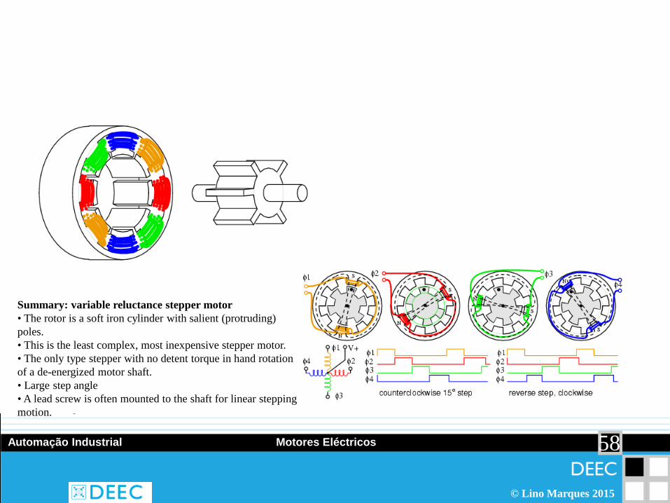
Summary: variable reluctance stepper motor • The rotor is a soft iron cylinder with salient (protruding) poles. • This is the least complex, most inexpensive stepper motor. • The only type stepper with no detent torque in hand rotation of a de-energized motor shaft. • Large step angle • A lead screw is often mounted to the shaft for linear stepping motion.

59 Automação Industrial Motores Eléctricos
© Lino Marques 2015
Motor de passo de imanes permanentes

60 Automação Industrial Motores Eléctricos
© Lino Marques 2015
Comando bipolar e unipolar

61 Automação Industrial Motores Eléctricos
© Lino Marques 2015
Comando em passo completo

62 Automação Industrial Motores Eléctricos
© Lino Marques 2015
Meio-passo
63 Automação Industrial Motores Eléctricos
© Lino Marques 2015
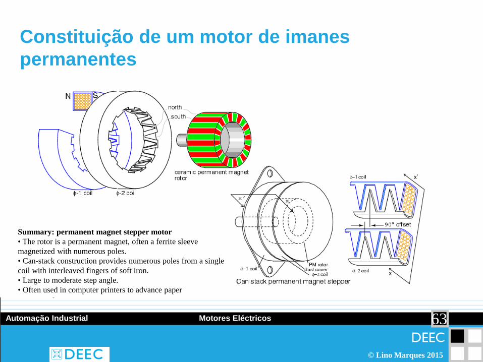
Constituição de um motor de imanes permanentes
Summary: permanent magnet stepper motor • The rotor is a permanent magnet, often a ferrite sleeve magnetized with numerous poles. • Can-stack construction provides numerous poles from a single coil with interleaved fingers of soft iron. • Large to moderate step angle. • Often used in computer printers to advance paper
64 Automação Industrial Motores Eléctricos
© Lino Marques 2015
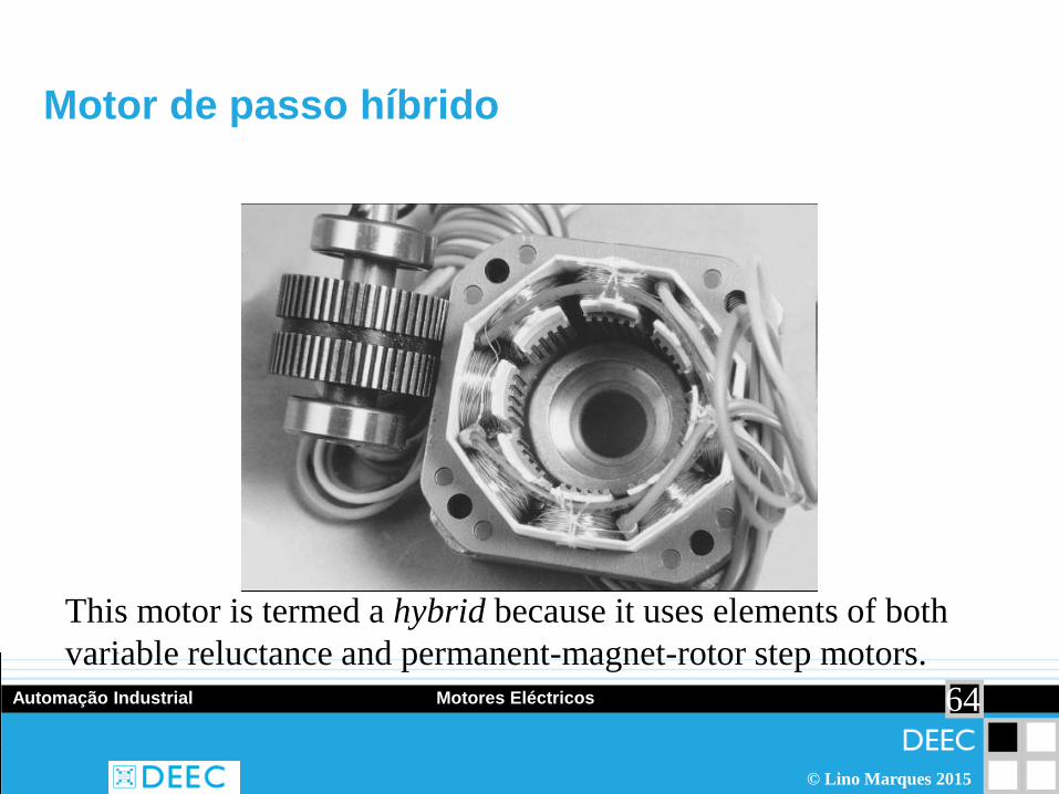
Motor de passo híbrido
This motor is termed a hybrid because it uses elements of both variable reluctance and permanent-magnet-rotor step motors.

65 Automação Industrial Motores Eléctricos
© Lino Marques 2015
Constituição

66 Automação Industrial Motores Eléctricos
© Lino Marques 2015
Rotação do motor híbrido
Summary: hybrid stepper motor • The step angle is smaller than variable reluctance or permanent magnet steppers. • The rotor is a permanent magnet with fine teeth. North and south teeth are offset by half a tooth for a smaller step angle. • The stator poles have matching fine teeth of the same pitch as the rotor. • The stator windings are divided into no less than two phases. • The poles of one stator windings are offset by a quarter tooth for an even smaller step angle.

67 Automação Industrial Motores Eléctricos
© Lino Marques 2015
Modos de comando
• Wave Drive (1 phase on) • Full Step Drive (2 phases on) • Half Step Drive (1 & 2 phases on) • Microstepping (Continuously varying motor currents)


![Manual Variador [e]-MOTION SACI](https://img.document.onl/doc/110x75/62df00c57f1bbd34273adde0/manual-variador-e-motion-saci.jpg)