Embed Size (px)
Citation preview

PREPARATION AND CHARACTERIZATION OF HYDROTALCITE COATINGS TO PROTECT ALUMINIUM ALLOYS
S.M.C.Fernandes1, O.V. Correa1, J.A. Souza1, R.A. Antunes2, N.B de Lima1, L.V.Ramanathan1
1 Instituto de Pesquisas Energéticas e Nucleares (IPEN / CNEN - SP)
Av. Professor Lineu Prestes 2242 05508-000 São Paulo, SP
2 Centro de Engenharia, Modelagem e Ciências Sociais (CECS), Universidade Federal do ABC, 09210-170, Santo André-SP.
ABSTRACT
Pitting corrosion of the aluminium alloy cladding of spent research reactor fuels during wet storage is the main form of degradation. To prevent this, hydrotalcite (HTC) based coatings were proposed. This paper presents the effect of chemical bath parameters on the microstructure of HTC coatings and the corrosion behavior of HTC coated AA 6061 specimens. The HTC coating formed at 98 °C from nitrate baths and referred to as HT-HTC was homogeneous and consisted of intersecting blade-like crystallites. Electrochemical tests revealed that HT-HTC coated specimens that were treated in a cerium salt solution were the most resistant to corrosion. Field tests in which un-coated and HTC coated AA 6061 alloy coupons as well as full-size plates were exposed to the IEA-R1 reactor’s spent fuel basin for 23 months corroborated the high corrosion resistance imparted by the HT-HTC + Ce coating. The mechanism by which the HTC coating and cerium protect the Al alloy is discussed. Key words: Hydrotalcite, coatings, corrosion, aluminum alloy. INTRODUCTION
In most countries spent aluminum-clad nuclear fuels from research reactors (RRs) are stored in light water filled pools for decades. Despite water quality management programs at the fuel storage facilities, pitting corrosion has been reported. This form of degradation could lead to cladding breach, release of fissile material and radioactive contamination of the storage facilities. [1] Pitting corrosion of the fuel cladding has been attributed to synergism in the effect of some basin water parameters on corrosion of aluminum alloys. [1,2] Hence, it was imperative to protect the Al cladding of spent RR fuel. A RR fuel, also referred to as a fuel assembly, consists of an assembly of 18 or more Al-clad fuel plates. The complex shape of the
22º CBECiMat - Congresso Brasileiro de Engenharia e Ciência dos Materiais06 a 10 de Novembro de 2016, Natal, RN, Brasil
6793

fuel assembly and its high radioactivity preclude electrochemical surface treatments. Thus chemical surface treatment to form a coating is the only option. Conversion coatings (CC) have been widely used in many industries to protect a variety of metals. A chromium based CC is considered a near ideal coating for many metals. However, chromates being carcinogenic and a toxic substance are being progressively phased out. A significant amount of data is available on potential chromate replacements for Al alloys and these include molybdates, permanganates, phosphates, refractory metal oxyflourides, silanes, sol-gels, self-assembling monolayers, conductive polymers, cobalt based coatings, hydrotalcites and rare earths. [3] It is well known that in alkaline solutions Al exhibits a high dissolution rate, but surprisingly when Al is immersed in an alkaline lithium salt solution it forms a continuous surface film which confers passivity. The composition of this film has been reported to be predominantly La2 [Al2(OH)6]2.CO3.nH2O (lithium aluminum hydroxide-carbonate (or nitrate)-hydrate), that belongs to the hydrotalcite mineral family, a form of ‘talc’. [4-6] Hence, hydrotalcite (HTC) was considered to protect the aluminum cladding of spent nuclear fuel. This paper presents the preparation of HTC coatings on aluminum alloy AA 6061 specimens and the effect of bath composition, temperature and duration of treatment on the microstructure of the coating as well as on the corrosion behavior of uncoated and HTC coated Al alloy specimens. Rare earth compounds have been used as a corrosion inhibitor to protect aluminum alloys. [7-10] Preliminary investigations revealed that chemical treatments to form lanthanide based coatings on Al alloys AA 1100 and AA 6061increased the corrosion resistance of the alloys. [11, 12] Hence, the effect of cerium incorporation in the HTC coating on corrosion behavior of AA 6061 alloy was also studied. Further, field tests were carried out in which, un-coated and coated Al alloy coupons as well as full-size plates were exposed to a spent fuel basin for periods of up to months and then evaluated. METHODS AND MATERIALS
Aluminium alloy AA 6061-T6 (0.94 Mg, 0.65 Si, 0.25 Cu, 0.24 Fe, balance Al) is used to clad most research reactor fuels. Hence, this alloy was used in this investigation to prepare laboratory test specimens and field test coupons as well as plates. Different alkaline lithium salt solutions have been used to form HTC on a variety of Al alloys at many temperatures. [4] Table 1 shows the different solutions and the conditions under which these solutions were used to coat and post-treat the specimens, coupons and plates. The specimens, coupons and plates were degreased and deoxidized prior to immersion in the lithium nitrate solution at 98 °C or in the lithium carbonate solution at room temperature (R.T.). The coatings obtained from these solutions were referred to as HT-HTC and LT-HTC respectively. Cerium was incorporated in some of the HT-HTC coated specimens, coupons and plates by immersion in solution 5 and in some of the LT-HTC coated specimens by immersion in solution 6 followed by rinsing in deionized water. A set of experiments were also carried out in which Al specimens were immersed for different duration at room temperature in the lithium nitrate solution prepared to obtain HT-HTC. The effect of
22º CBECiMat - Congresso Brasileiro de Engenharia e Ciência dos Materiais06 a 10 de Novembro de 2016, Natal, RN, Brasil
6794

additives such as H2O2 and K2S2O8 to this solution on HTC coating features was also studied. (solutions 7 to 10 in Table 1) These experiments were carried out to obtain an all room temperature process to enable scale-up to treat radioactive spent fuels. X-ray diffraction analysis of the coatings formed from solutions 1 and 2 of Table 1 was performed. The thickness of the coating formed from solution 3 was adequate to carry out grazing angle diffraction analysis. However, the thickness of the coating formed from solution 4 was insufficient for XRD analysis. Hence a powder sample of the Al alloy, with substantially increased surface area to volume ratio, was treated in solution 4 to form a sufficient amount of coating, and then analyzed in the diffractometer. The surfaces of the HTC coated specimens were examined in a FEG-scanning electron microscope.
Table 1: Solutions and conditions used to prepare HTC coatings on Al alloys. [13]
Solution Purpose Composition of solution and conditions
1 Degrease 25 g/L Na2SiO3; 25 g/L Na2CO3; 65 °C; 2 min.
2 Deoxidise 10% HNO3; 3% NaBrO3; 55 °C; 3 min.
3 Form HT-HTC 6.9g/L LiNO3; 28.3 g/L KNO3; 2.4 g/L LiOH; 0.06 g/L NaAlO2; 98 °C; pH 12; 10 min.
4 Form LT-HTC 0.1M Li2CO3; LiOH; Al; pH 12; 15 min; R.T.
5 Incorporate Ce 0.1% CeCl3; 97 °C; pH 4; 5 min.
6 Incorporate Ce 10 g/L Ce (NO3)3; 30% H2O2; R.T.; 5 min. 7 Form HT-HTC at
room temperature 6.9g/L LiNO3; 28.3 g/L KNO3; 2.4 g/L LiOH; 0.06 g/L NaAlO2; R.T.; pH 12; 10 min.
8 Form HT-HTC at room temperature
6.9g/L LiNO3; 28.3 g/L KNO3; 2.4 g/L LiOH; 0.06 g/L NaAlO2; 30 vol% H2O2; R.T.; pH 12; 10 min.
9 Form HT-HTC at room temperature
6.9g/L LiNO3; 28.3 g/L KNO3; 2.4 g/L LiOH; 0.06 g/L NaAlO2; 2.5 g/L K2S2O8; R.T.; pH 12; 10 min.
10 Form HT-HTC at room temperature
6.9g/L LiNO3; 28.3 g/L KNO3; 2.4 g/L LiOH; 0.06 g/L NaAlO2; 30 vol% H2O2; 2.5g/L K2S2O8; R.T.; pH 12; 10 min.
11 Sealing MgC4H6O4; 82 °C; 15 min.
R.T. – room temperature The electrochemical behavior of uncoated and coated specimens 20 mm x 20 mm was determined in 0.01 M NaCl solution at room temperature. Anodic potentiodynamic polarization measurements were carried out with a standard 3-electrode arrangement consisting of a working electrode, a saturated calomel reference electrode and a platinum counter electrode. The potential was scanned from – 1.0 V to + 0.4 V at 0.1 mV/s. Field tests were carried out and this consisted of preparing uncoated and HTC coated AA 6061 alloy coupons (10 cm in diameter and 3 mm thick ) and full-size plates (62.5 cm x 7.0 cm to resemble fuel plates). The coupons were assembled in racks and the plates were assembled to form dummy fuel elements. [1] Preparation of uncoated and HTC coated coupons and plates was done using the solutions and conditions shown in Table1. The racks and dummy elements were placed in the spent fuel section of the IEA-R1 research reactor in IPEN, Brazil, for periods of up to
22º CBECiMat - Congresso Brasileiro de Engenharia e Ciência dos Materiais06 a 10 de Novembro de 2016, Natal, RN, Brasil
6795

5 and 23 months respectively and then withdrawn. These withdrawn racks and dummy fuels were then rinsed, decontaminated, disassembled and the surfaces of the coupons/plates examined with an optical microscope. RESULTS
Composition and microstructure of the coatings
The x-ray diffraction spectra of the coatings on AA 6061 treated in solution 3 at 98 °C and in solution 4 at room temperature are shown in Figure 1. The spectra revealed HTC formation in both solutions. Some bayerite was also detected in the coating formed in solution 4 at room temperature. The amount of HTC formed was quite thin as only a few peaks corresponding to (Li2 [Al2(OH)6]2CO3 3H2O) were discernible. The HTC formed as a coating on the sheet specimen surface in solution 3 was thicker and easily identified from the JCPDS file.
10 20 30 40 50 60 70 80
Nordstrandite Al(OH)3
Bayerite Al(OH)3
Li2[Al
2(OH)
6]2CO
33H
2O
Al#
*0
+
++++
+++++++
+
0
0
0
0
0
0
#
#
##
*****
Inte
nsity (
a.u
.)
2 (degrees)
(a) (b)
Figure 1: X-ray diffraction spectra revealing HTC formed on AA 6061 specimens in the: (a) nitrate bath at 98 °C (Cr-Kα); (b) carbonate bath at room temperature (Cu-
Kα).
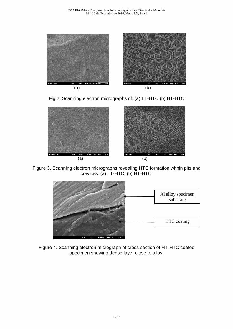
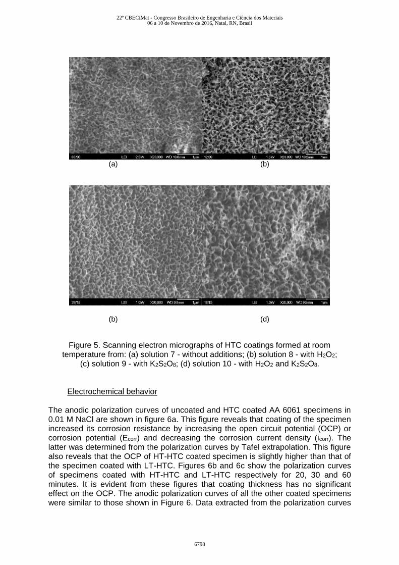
The HTC coatings formed from solutions 3 and 4 were uniform and their morphologies are shown in Figure 2. The surfaces revealed intersecting blade-like crystallites of HTC that formed a layer across the surface. The HTC also formed inside pits and recesses that were created during pre-treatment of the substrate as shown in Figure 3. Typical HT-HTC coating thickness after 10 minutes of immersion was ~2 µm. A dense layer of amorphous or nanocrystalline HTC forms underneath the top layer as shown in figure 4. [5, 6] The coating thickness increased with duration of treatment in solutions 3 and 4, but no change in morphology was observed with duration of treatment. The micrographs in figure 5 reveal that coatings formed at room temperature in the solution used to obtain HT-HTC coatings does indeed result in well-formed HTC, with features similar to that obtained at the higher temperature. The addition of an activating agent like H2O2 or K2S2O8 resulted in HTC with interconnected platelets, essential to incorporate cerium. However in the presence of both the activating agents the HTC coating was not as well formed.
20 30 40 50 60 70 80
* Li2[Al
2(OH)
6]2NO
33H
2O
# Al # #
*
**
**
**
*
*
Inte
nsity (
a.u
.)
20
22º CBECiMat - Congresso Brasileiro de Engenharia e Ciência dos Materiais06 a 10 de Novembro de 2016, Natal, RN, Brasil
6796
(a) (b)
Fig 2. Scanning electron micrographs of: (a) LT-HTC (b) HT-HTC
(a) (b)
Figure 3. Scanning electron micrographs revealing HTC formation within pits and crevices: (a) LT-HTC; (b) HT-HTC.
Figure 4. Scanning electron micrograph of cross section of HT-HTC coated specimen showing dense layer close to alloy.
Al alloy specimen
substrate
HTC coating
22º CBECiMat - Congresso Brasileiro de Engenharia e Ciência dos Materiais06 a 10 de Novembro de 2016, Natal, RN, Brasil
6797
(a) (b)
(b) (d)
Figure 5. Scanning electron micrographs of HTC coatings formed at room
temperature from: (a) solution 7 - without additions; (b) solution 8 - with H2O2; (c) solution 9 - with K2S2O8; (d) solution 10 - with H2O2 and K2S2O8.
Electrochemical behavior
The anodic polarization curves of uncoated and HTC coated AA 6061 specimens in 0.01 M NaCl are shown in figure 6a. This figure reveals that coating of the specimen increased its corrosion resistance by increasing the open circuit potential (OCP) or corrosion potential (Ecorr) and decreasing the corrosion current density (icorr). The latter was determined from the polarization curves by Tafel extrapolation. This figure also reveals that the OCP of HT-HTC coated specimen is slightly higher than that of the specimen coated with LT-HTC. Figures 6b and 6c show the polarization curves of specimens coated with HT-HTC and LT-HTC respectively for 20, 30 and 60 minutes. It is evident from these figures that coating thickness has no significant effect on the OCP. The anodic polarization curves of all the other coated specimens were similar to those shown in Figure 6. Data extracted from the polarization curves
22º CBECiMat - Congresso Brasileiro de Engenharia e Ciência dos Materiais06 a 10 de Novembro de 2016, Natal, RN, Brasil
6798

of the different specimens are summarized in 5 different tables (Tables 2-6) to facilitate comparisons and observe the effect of different parameters.
(a) (b)
(c)
Figure 6. Polarization curves of uncoated and HTC coated AA 6061 specimens in 0.01 M NaCl. (a) Uncoated, HT-HTC and LT-HTC coated; (b) HT-HTC coated for
different duration; (c) LT-HTC coated for different duration. Table 2. Effect of HTC coating on electrochemical parameters of AA 6061 in 0.01 M
NaCl.
Specimen condition Ecorr (V) icorr (A.cm-2)
Untreated -0.79 1.56
HT-HTC (20ˈ) -0.58 0.35
LT-HTC (20ˈ) -0.59 0.77
-1.2
-0.8
-0.4
0
0.4
-10 -9 -8 -7 -6 -5 -4 -3 -2
E (
V)
Log i (A.cm-2)
HT-HTC 20'
HT-HTC 30'
HT-HTC 60'
-1.2
-0.8
-0.4
0
0.4
-9 -8 -7 -6 -5 -4 -3 -2
E (
V)
Log i (A.cm-2)
Untreated
HT-HTC 20'
LT-HTC 20'
-1
-0.6
-0.2
0.2
-9 -8 -7 -6 -5 -4 -3 -2
E (
V)
Log i (A.cm-2)
LT-HTC 20'
LT-HTC 30'
LT-HTC 60'
22º CBECiMat - Congresso Brasileiro de Engenharia e Ciência dos Materiais06 a 10 de Novembro de 2016, Natal, RN, Brasil
6799

Table 3. Effect of duration of HT-HTC formation on electrochemical parameters of uncoated and coated AA 6061 in 0.01 M NaCl.
Specimen condition Ecorr (V) icorr (A.cm-2)
Untreated -0.79 1.56
HT-HTC (20ˈ) -0.58 0.35
HT-HTC (30ˈ) -0.57 0.78
HT-HTC (60ˈ) -0.58 0.93
Table 4. Effect of duration of LT-HTC formation on electrochemical parameters of uncoated and coated AA 6061 in 0.01 M NaCl.
Specimen condition Ecorr (V) Icorr (A.cm-2)
Untreated -0.79 1.56
LT-HTC (20ˈ) -0.59 0.77
LT-HTC (30ˈ) -0.59 0.46
LT-HTC (60ˈ) -0.60 0.72
Table 5. Effect of duration of cerium treatment of HT-HTC coated AA 6061 specimens on electrochemical parameters in 0.01 M NaCl.
Specimen condition Ecorr (V) icorr (A.cm-2)
HT-HTC (20ˈ) -0.58 0.35
HT-HTC (20ˈ) + Ce (5ˈ) -0.60 0.26
HT-HTC (20ˈ) + Ce (10ˈ) -0.59 0.12
HT-HTC (20ˈ) + Ce (15ˈ) -0.59 0.37
Table 6. Effect of duration of cerium treatment of LT-HTC coated AA 6061 specimens on electrochemical parameters in 0.01 M NaCl.
Specimen condition Ecorr (V) icorr (A.cm-2)
LT-HTC (20ˈ) -0.59 0.77
LT-HTC (20ˈ) + Ce (5ˈ) -0.58 0.96
LT-HTC (20ˈ) + Ce (10ˈ) -0.56 0.78
LT-HTC (20ˈ) + Ce (15ˈ) -0.58 0.71
Table 2 shows that either type of coating increases corrosion resistance of the Al alloy in NaCl solution. That is, the corrosion potential (Ecorr) increases and the corrosion current density (icorr) decreases. The icorr values of HT-HTC and LT-HTC coated specimens indicate that the latter is less protective. Table 3 shows that the icorr of specimens coated with HT-HTC for longer times increased with duration of
22º CBECiMat - Congresso Brasileiro de Engenharia e Ciência dos Materiais06 a 10 de Novembro de 2016, Natal, RN, Brasil
6800
treatment in the lithium nitrate solution. This increase in icorr is due to the following reasons: HTC coating formation involves two simultaneous processes - dissolution of Al accompanied with hydrogen evolution and deposition of HTC. The HT-HTC formed on the specimen surface after 30 and 60 minutes is from a bath with reduced amount of Al ions and contain increasing amounts of co-deposited alloying and/or impurity elements that dissolved from the substrate. The icorr on the other hand of specimens coated with LT-HTC for 20, 30 and 60 min did not vary significantly as shown in Table 4. The reason being that the LT-HTC coating thickness after even 60 minutes is not significant enough to cause appreciable depletion of Al ions in solution 4. Table 5 shows that incorporation of Ce in HT-HTC does not alter Ecorr of the specimen but decreases the icorr. This table also shows that increase in duration of Ce treatment has no marked effect on icorr. Table 6 shows that cerium incorporation in the LT-HTC coating from the cerium nitrate bath containing H2O2 as an accelerator needs to be done for at least 15 minutes to observe decrease of icorr.
Coupons and plates exposed to IEA-R1 reactor spent fuel section.
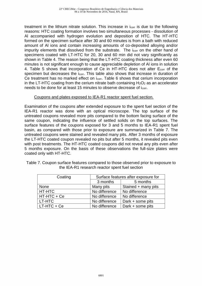
Examination of the coupons after extended exposure to the spent fuel section of the IEA-R1 reactor was done with an optical microscope. The top surface of the untreated coupons revealed more pits compared to the bottom facing surface of the same coupon, indicating the influence of settled solids on the top surfaces. The surface features of the coupons exposed for 3 and 5 months to IEA-R1 spent fuel basin, as compared with those prior to exposure are summarized in Table 7. The untreated coupons were stained and revealed many pits. After 3 months of exposure the LT-HTC coated coupon revealed no pits but after 5 months, it revealed pits even with post treatments. The HT-HTC coated coupons did not reveal any pits even after 5 months exposure. On the basis of these observations the full-size plates were coated only with HT-HTC. Table 7. Coupon surface features compared to those observed prior to exposure to
the IEA-R1 research reactor spent fuel section
Coating Surface features after exposure for
3 months 5 months
None Many pits Stained + many pits
HT-HTC No difference No difference
HT-HTC + Ce No difference No difference
LT-HTC No difference Dark + some pits
LT-HTC + Ce No difference Dark + some pits
22º CBECiMat - Congresso Brasileiro de Engenharia e Ciência dos Materiais06 a 10 de Novembro de 2016, Natal, RN, Brasil
6801

Table 8. Uncoated and coated plate surface features after 23 months exposure to the IEA-R1 reactor’s spent fuel section.
Coating Surface features on both sides
None Many pits. Surface stained dark all over.
HTC No pits. Top 2/3rds stained dark grey.
HTC + Ce No pits. Top 2/3rds stained light grey.
HTC + Ce + sealed No pits. Bright plate, unstained.
The plates exposed for 23 months were examined visually and with an optical microscope and the main surface features are summarized in Table 8. The plates were stained due to formation of thicker surface oxide. The uncoated plates revealed a number of pits and the HTC coated plates although stained and dark, did not reveal any pits. DISCUSSION The electrochemical measurements and field tests have indicated a marked increase in corrosion resistance of AA 6061 coated with HT-HTC. The corrosion resistance was further enhanced by cerium incorporation in the coating. Cerium was chosen to enhance corrosion protection as it is the only rare earth (besides europium) that can involve a change in oxidation state and form a water insoluble hydroxide/oxide on Al. The faint yellow coating obtained upon immersion of the HTC coated coupon or plate in the cerium solution is constituted of an insoluble cerium hydroxide/oxide. [4, 14, 15] Progressive loss of the yellow color with time has been observed and attributed to the hydroxide transforming to oxide [16], or surface degradation of the surface peroxide containing species. The HTC layer imparts pitting corrosion protection by acting as a physical barrier between the solution and the surface. The higher corrosion resistance of HT-HTC coated specimens compared with LT-HTC coated specimens is due to the former being thicker, both the barrier and the top layer. Further, coarsening of the well-formed HT-HTC crystallites during long term exposure in the spent fuel section, akin to a hydrothermal treatment, increases even more the physical protection given by this coating. The mechanism by which the cerium in the HTC imparts protection is considered to be ‘active corrosion protection’, analogous to chromium coatings. Basically, this involves release of Ce ions from the coating, transport of Ce ions through the solution and its action at defect sites to stifle corrosion. It has been speculated that if a Ce4+ bearing inorganic coating contacts a solution, soluble Ce4+ is released into the solution. When these ions encounter reducing conditions, like those associated with exposed bare metal at coating defects, it reduces to Ce3+, which forms an insoluble hydroxide and precipitates. The precipitated cerium hydroxide at the defect then stifles further corrosion. [3,14] Another reason that can be attributed for the increased protection given by the HT-HTC+Ce compared with that given by LT-HTC+Ce is the presence of more Ce in HT-HTC, due mainly to availability of more sites on the HT-HTC surface for cerium to deposit compared to that on the LT-HTC surface.
22º CBECiMat - Congresso Brasileiro de Engenharia e Ciência dos Materiais06 a 10 de Novembro de 2016, Natal, RN, Brasil
6802
CONCLUSIONS
1. Hydrotalcite (HTC) coatings on AA 6061 alloy were formed in a nitrate bath at
98 °C and a carbonate bath at room temperature. 2. HTC coatings with desired surface features were formed at room temperature
from HT-HTC baths that were cooled to room temperature and also in the presence of activating agents.
3. HT-HTC coating increased corrosion resistance of the alloy more than the LT-HTC coating.
4. Cerium incorporation in the HT-HTC coating increased further the corrosion resistance of the alloy.
5. The corrosion resistance of HT-HTC coated specimens decreased slightly with increase in duration of HTC formation.
6. The corrosion resistance of the LT-HTC coated specimens did not vary with increase in duration of HTC formation.
7. Effect of cerium incorporation in the LT-HTC on corrosion resistance of the alloy was evident only after 20 minutes of treatment.
8. Coupons and full-size plates coated with HT-HTC and exposed to the IEA-R1 reactor spent fuel section for 23 months did not reveal any pits, indicating marked potential for use of HT-HTC as a protective coating on spent RR fuel during long term wet storage.
REFERENCES
1. Corrosion of Research Reactor Aluminium Clad Spent Fuel in Water”, IAEA -
TRS 418, 2003. 2. RAMANATHAN, L.V.; HADDAD, R.; ADELFANG, P.; RITCHIE, I.G. Corrosion
of Spent Aluminium-clad Research Reactor Fuel – Synergism in the Role of
Storage Basin Water Parameters, Proceedings of 12th International topical
meeting on Research Reactor Fuel Management (RRFM), Hamburg,
Germany, 2008.
3. HARVEY, T.G. Cerium based conversion coatings on aluminium alloys: a process review, Corrosion Engineering, Science and Technology, v.4, n.48, p.248-269, 2013.
4. BUCHHEIT, R.G.; BODE, M.D.; STONER, G.E. Corrosion-resistant, chromate-free talc coatings for aluminum, Corrosion, v.50, n.3, p.205-214, 1994.
5. DREWIEN, C.A.; EATOUGH, M.O.; TALLANT, T.R.; HILLS, C.R.; BUCHHEIT, R.G. Lithium-aluminum-carbonate-hydroxide hydrate coatings on aluminium alloys: Composition, structure, and processing bath chemistry, J.Mater. Res., v.11, p.1507-1513, 1996.
6. ZHANG, W.; BUCHHEIT, R.G. Hydrotalcite coating formation on Al-Cu-Mg alloys from oxidizing bath chemistries, Corrosion, v.58, n.7, p.591-600, 2002.
22º CBECiMat - Congresso Brasileiro de Engenharia e Ciência dos Materiais06 a 10 de Novembro de 2016, Natal, RN, Brasil
6803

7. HINTON, B.R.W.; ARNOTT, D.R.; RYAN, N.E. Cerium conversion coatings
for the corrosion protection of aluminium, Mater. Forum v.9, p.162-173, 1986.
8. ARNOTT, D.R.; RYAN, N.E.; HINTON, B.R.W.; SEXTON, B.A.; HUGHES, A.E. Auger and XPS studies of cerium corrosion inhibition on 7075 aluminum alloy, Appl. Surf. Sci., v.22/23, p.236-251, 1985.
9. DABALA, M.; ARMELAO, L.; BUCHBERGER, A.; CALLIARI, I. Cerium-based conversion layers on aluminum alloys, Appl. Surf. Sci., v.172, p.312-322, 2001.
10. HUGHES, A.E.; HARDIN, S.G.; WITTEL,K.W.; MILLER, P.R. Surface Conversion of Aluminum and Aluminum alloys for Corrosion Protection, in the Proceedings of the NACE meeting: Corrosion/2000, Research topical Symposium:, Orlando, USA, 2000.
11. FERNANDES, S.M.C.; CORREA, O.V.; DE SOUZA, J.A.; RAMANATHAN, L.V. A coating to protect spent aluminium-clad research reactor fuel assemblies during extended wet storage. In: Transactions of Research Reactor Fuel Management –RRFM2009, Vienna, Austria, 2009. http://www.euronuclear.org/meetings/rrfm2009/transactions/rrfm09-transactions-session-5.pdf 60-65.
12. FERNANDES, S.M.C.; CORREA, O.V.; DE SOUZA, J.A.; RAMANATHAN, L.V. Lanthanide based conversion coatings for long term wet storage of aluminium-clad spent fuel. In: Transactions of Research Reactor Fuel Management - RRFM2010, Marrakech, Morocco, 2010. http://www.euronuclear.org/meetings/rrfm2010/transactions/RRFM2010-transactions-s2.pdf, 111-115.
13. FERNANDES, S.M.C.; CORREA, O.V.; DE SOUZA, J.A.; RAMANATHAN, L.V. Antunes, R.A., Olivieira, M.C.L., Conversion coatings to protect aluminium-clad spent fuel in wet storage, Transactions of Research Reactor Fuel management - RRFM-2013, St. Petersburg, Russia, 132-139. http://www.euronuclear.org/meetings/rrfm2013/transactions/RRFM2013-fuel.pdf, 132-139.
14. BUCHHEIT, R.G.; MAMIDIPALLY, S.B.; SCHMUTZ, P.; GUAN, H. Active
corrosion protection in Ce-modified hydrotalcite conversion coatings,
Corrosion, v.58 n.1, p.3-14, 2002.
15. ARNOTT, D.R.; HINTON, B.R.W.; RYAN, N.E. Cationic film-forming inhibitors
for the corrosion protection of AA 7075 aluminum alloy in chloride solutions,
Mat. Performance, v.26, n.8, p.42-47, 1987.
16. ARNOTT, D.R.; HINTON, B.R.W.; RYAN, N.E. Cationic-film-forming inhibitors
for the protection of the AA7075 aluminum alloy against corrosion in aqueous
chloride solution, Corrosion, v.45, n.1, p.12-18, 1989.
17. SCHLOES, F.H.; SOSTE, C.; HUGHES, A.E.; HARDIN, S.G.; CURTIS, P.R.
The role of hydrogen peroxide in the deposition of cerium based conversion
coatings Appl. Surf. Sci., v.253, n.4, p.1770-1780, 2006.
22º CBECiMat - Congresso Brasileiro de Engenharia e Ciência dos Materiais06 a 10 de Novembro de 2016, Natal, RN, Brasil
6804