Embed Size (px)
Citation preview

www.signion.comJULY 2005
SSIIGGNNIIOONN SSYYSSTTEEMMSS PPVVTT.. LLTTDD..Plot # 71 & 72
ANRICH Industrial EstateI.D.A Bollarum
Medak Dist. – 502325INDIA
Tel/Fax: +91 (8458) 279321E-mail: [email protected]
SSAATTCCOOMM MMOODDEEMMUUSSEERR’’SS GGUUIIDDEE

SATCOM MODEM USER’S GUIDE
SIGNION SYSTEMS
1
SATCOM MODEM USER’S GUIDE
SIGNION SYSTEMS
2
Important notes
Signion Systems (Signion) provides the SATCOM MODEMunder the following conditions:
1. This unit, intended for engineering development, shouldnot be considered a finished product as it may not becomplete in terms of required design, marketing,and/or manufacturing related protective considerations,including product safety measures typically found in theend product. As a prototype, this product does not fallwithin the scope of the European Union directive onelectromagnetic compatibility and therefore may notmeet technical requirements of the directive.
2. Should your SATCOM MODEM not meet thespecifications indicated in this User’s Guide, it may bereturned within 30 days from the date of delivery, in itsoriginal packing, for a full refund. This is the exclusivewarranty made by the seller to the buyer and is in lieuof all other warranties, expressed, implied or statutory.
3. The user assumes all responsibility and liability forproper and safe handling of the unit. Further, the userindemnifies Signion from all claims arising from thehandling or use of the goods. Please be aware that theunit received may not be regulatory compliant oragency certified (FCC, UL, CE, etc). Precautions withregard to electrostatic discharge, EMI/EMC complianceand electrical safety are the user’s responsibility.
4. Except to the extent of the indemnity set forth above,neither party shall be liable to the other for anyindirect, special, incidental or consequential damages.
5. Because Signion currently deals with a variety ofcustomers, our arrangement with the user is notexclusive. Signion assumes no liability for applicationsassistance, customer product design or infringement ofpatents.
6. Prior to handling the SATCOM MODEM, please read theUser’s Guide in full, giving special attention to theWarnings and Restrictions. For further safety concernsplease contact our application engineer [email protected].
7. Persons handling this product must have electronicstraining and observe good laboratory practicestandards.
8. No license is granted under any patent right or otherintellectual property right of Signion covering orrelating to any machine, process, or combination inwhich such Signion products or service might be used.
SATCOM MODEM USER’S GUIDE
SIGNION SYSTEMS
3
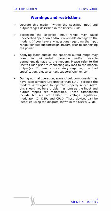
Warnings and restrictions
Operate this modem within the specified input andoutput ranges described in the User’s Guide.
Exceeding the specified input range may causeunexpected operation and/or irreversible damage to themodem. If you have any questions regarding the inputrange, contact [email protected] prior to connectingthe power.
Applying loads outside the specified output range mayresult in unintended operation and/or possiblepermanent damage to the modem. Please refer to theUser’s Guide prior to connecting any load to the modemoutput(s). If there is uncertainty regarding the loadspecification, please contact [email protected].
During normal operation, some circuit components mayhave case temperature greater than 60°C. Because themodem is designed to operate properly above 60°C,this should not be a problem as long as the input andoutput ranges are maintained. These componentsinclude but are not limited to voltage regulators,modulator IC, DSP, and CPLD. These devices can beidentified using the diagram shown in the User’s Guide.

SATCOM MODEM USER’S GUIDE
SIGNION SYSTEMS
4
Contents
Introduction 6
Quick start 7
Testing and performance evaluation 8
Configuration details 14
Specifications 17
Appendix A: Interface details 19
Appendix B: Ambiguity encoding 20
Appendix C: Modulator spectrum 21
Appendix D: Modulator eye patterns 23
Appendix E: Troubleshooting 24
Appendix F: Default jumper settings 25
SATCOM MODEM USER’S GUIDE
SIGNION SYSTEMS
5
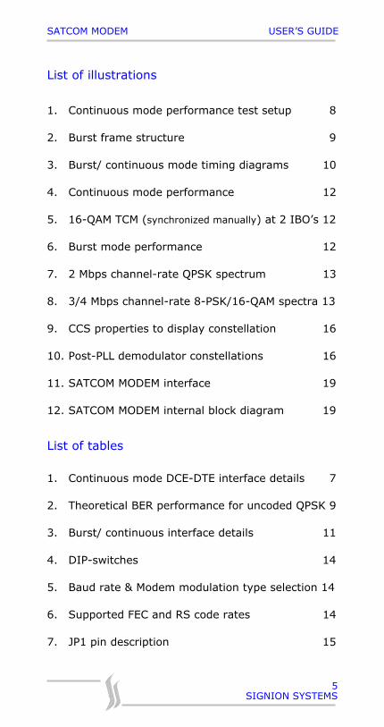
List of illustrations
1. Continuous mode performance test setup 8
2. Burst frame structure 9
3. Burst/ continuous mode timing diagrams 10
4. Continuous mode performance 12
5. 16-QAM TCM (synchronized manually) at 2 IBO’s 12
6. Burst mode performance 12
7. 2 Mbps channel-rate QPSK spectrum 13
8. 3/4 Mbps channel-rate 8-PSK/16-QAM spectra 13
9. CCS properties to display constellation 16
10. Post-PLL demodulator constellations 16
11. SATCOM MODEM interface 19
12. SATCOM MODEM internal block diagram 19
List of tables
1. Continuous mode DCE-DTE interface details 7
2. Theoretical BER performance for uncoded QPSK 9
3. Burst/ continuous interface details 11
4. DIP-switches 14
5. Baud rate & Modem modulation type selection 14
6. Supported FEC and RS code rates 14
7. JP1 pin description 15
SATCOM MODEM USER’S GUIDE
SIGNION SYSTEMS
6
About this document
This manual describes Signion’s high speed DSP basedSATCOM MODEM, providing details of the following:
Hardware interface Test setup and configuration Performance in the presence of AWGN System specifications Troubleshooting
Introduction
The SATCOM MODEM provides flexible data rates at 70 MHzIF, while supporting a variety of modulation (BPSK/ QPSK/8-PSK/ 16-QAM) and coding (Viterbi/ trellis and R-S)options, http://www.signion.com/satradio.pdf. The 16-QAMdemodulator’s advanced non-decision directed phaseacquisition and TCM decoder’s constellation adaptation, overa wide amplifier back-off range, allows continuous modeoperation, with negligible degradation, for many amplifiertypes (TWTA, GaAsFET, SSPA, etc.).
It offers state of the art performance and reliability with thebest features of a programmable modem, all at theindustry’s lowest price. Sophisticated digital signalprocessing eliminates all on board physical adjustments andprovides superior performance.
The SATCOM MODEM has an advanced receive acquisitionand tracking system. It offers fast acquisition over a widerange of frequency offsets.
SATCOM MODEM USER’S GUIDE
SIGNION SYSTEMS
7
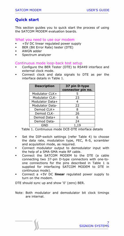
Quick start
This section guides you to quick start the process of usingthe SATCOM MODEM evaluation boards.
What you need to use our modem +5V DC linear regulated power supply BER (Bit Error Rate) tester (DTE) AWGN adder Spectrum analyzer
Continuous mode loop-back test setup Configure the BER Tester (DTE) to RS449 interface and
external clock mode. Connect clock and data signals to DTE as per the
interface details in Table 1.
Description 37 pin D-typeconnector pin no.
Modulator CLK+ 5Modulator CLK- 23
Modulator Data+ 4Modulator Data- 22
Demod CLK+ 8Demod CLK- 26
Demod Data+ 6Demod Data- 24
GND 1,19Table 1. Continuous mode DCE-DTE interface details
Set the DIP-switch settings (refer Table 4) to choosethe data rate, modulation type, FEC, R-S, scramblerand acquisition mode, as required.
Connect modulator output to demodulator input withthe help of a SMA-SMA male RF cable.
Connect the SATCOM MODEM to the DTE (a cableconnecting two 37-pin D-type connectors with one-to-one connections for the pins described in Table 1 issupplied for interfacing SATCOM MODEM to DTE incontinuous mode).
Connect a +5V DC linear regulated power supply toturn on the modem.
DTE should sync up and show ‘0’ (zero) BER.
Note: Both modulator and demodulator bit clock timingsare internal.
SATCOM MODEM USER’S GUIDE
SIGNION SYSTEMS
8
Testing and performance evaluation
Adjudicate modem performance by testing it with AWGN(Additive White Gaussian Noise).
Testing in presence of AWGNThe bit energy (Eb) to noise energy per unit bandwidth (N0),in any communication channel is given by the relation,
Gaussian distributed random noise, based on desired Eb/N0,is added to the modulated signal before it is fed to thedemodulator for processing. The actual data bitstransmitted are compared with the demodulated data tofind the probability of bit error (Pe) using the relation,
Modem test procedure
1. Continuous mode
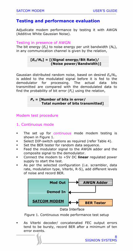
The set up for continuous mode modem testing isshown in Figure 1.
Select DIP-switch options as required (refer Table 4). Set the BER tester for random data sequence. Feed the modulator signal to the AWGN adder and the
composite signal to the demodulator. Connect the modem to +5V DC linear regulated power
supply to start the test. As per the selected configuration (i.e. scrambler, data
rate, modulation type, Viterbi, R-S), add different levelsof noise and record BER.
Data Interface
Mod Out
Demod In SATCOM MODEM
AWGN Adder
BER Tester
Figure 1. Continuous mode performance test setup
As Viterbi decoder/ concatenated FEC output errorstend to be bursty, record BER after a minimum of tenerror events.
[Eb/N0] = [(Signal energy/Bit Rate)/ (Noise power/Bandwidth)]
Pe = [Number of bits in error/ Total number of bits transmitted]
SATCOM MODEM USER’S GUIDE
SIGNION SYSTEMS
9
The observed BER at different Eb/N0 levels can betabulated as shown below:
S.No. Eb/N0 (dB) BER1. 12 8e-92. 10 4e-63. 8 1.8e-44. 6 2.5e-3
Table 2. Theoretical BER performance for uncoded QPSK
2. Burst mode
SATCOM MODEM supports uncoded, convolutional and TCMencoded (K=7, rate ½ FEC) data in burst mode, with thefollowing format and timing details:
Burst format:
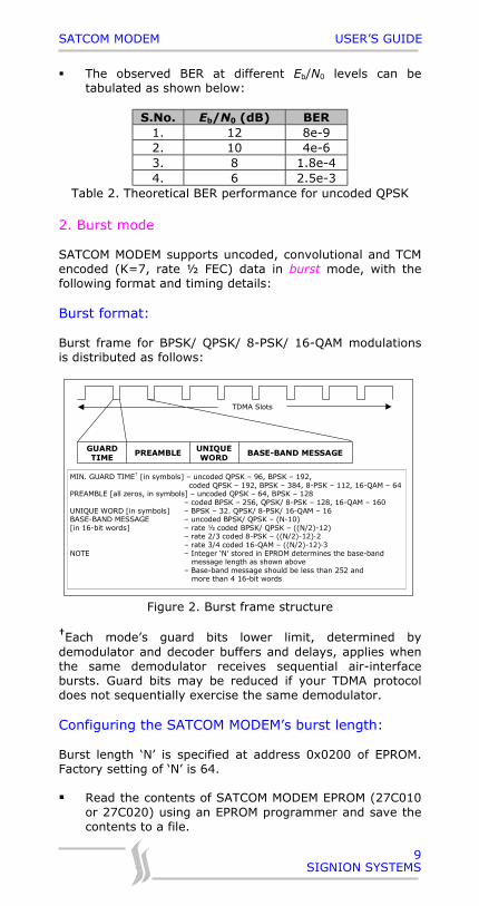
Burst frame for BPSK/ QPSK/ 8-PSK/ 16-QAM modulationsis distributed as follows:
MIN. GUARD TIME† [in symbols] – uncoded QPSK – 96, BPSK – 192, coded QPSK – 192, BPSK – 384, 8-PSK – 112, 16-QAM – 64
PREAMBLE [all zeros, in symbols] – uncoded QPSK – 64, BPSK – 128 – coded BPSK – 256, QPSK/ 8-PSK – 128, 16-QAM – 160 UNIQUE WORD [in symbols] – BPSK – 32. QPSK/ 8-PSK/ 16-QAM – 16 BASE-BAND MESSAGE – uncoded BPSK/ QPSK – (N-10) [in 16-bit words] – rate ½ coded BPSK/ QPSK – ((N/2)-12) – rate 2/3 coded 8-PSK – ((N/2)-12)·2 – rate 3/4 coded 16-QAM – ((N/2)-12)·3 NOTE – Integer ‘N’ stored in EPROM determines the base-band message length as shown above – Base-band message should be less than 252 and more than 4 16-bit words
TDMA Slots
PREAMBLE GUARD TIME
UNIQUE WORD
BASE-BAND MESSAGE
Figure 2. Burst frame structure
†Each mode’s guard bits lower limit, determined bydemodulator and decoder buffers and delays, applies whenthe same demodulator receives sequential air-interfacebursts. Guard bits may be reduced if your TDMA protocoldoes not sequentially exercise the same demodulator.
Configuring the SATCOM MODEM’s burst length:
Burst length ‘N’ is specified at address 0x0200 of EPROM.Factory setting of ‘N’ is 64.
Read the contents of SATCOM MODEM EPROM (27C010or 27C020) using an EPROM programmer and save thecontents to a file.
SATCOM MODEM USER’S GUIDE
SIGNION SYSTEMS
10
Erase the EPROM, by exposing its window to ultra-violetrays. Load the file that was saved; now edit the byte ataddress 0x0200 to the desired burst length ‘N’ and thenprogram the EPROM.
Place the EPROM in its socket and power ON theSATCOM MODEM. The new configuration is now set.
Burst mode timing:
A15 A14 A13 A12 A2 A1 A0 B15 B14
MCLK
DATA
FSYNC
N 16-BIT WORD DATA BURST
1 2 N FSYNC
DCLK
B13
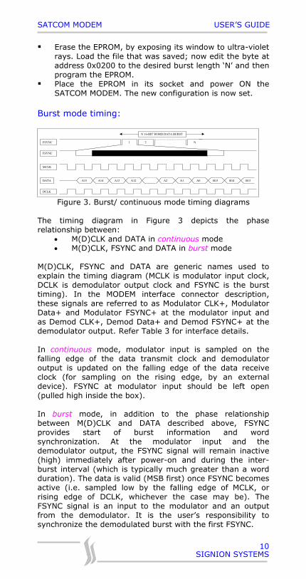
Figure 3. Burst/ continuous mode timing diagrams
The timing diagram in Figure 3 depicts the phaserelationship between:
• M(D)CLK and DATA in continuous mode• M(D)CLK, FSYNC and DATA in burst mode
M(D)CLK, FSYNC and DATA are generic names used toexplain the timing diagram (MCLK is modulator input clock,DCLK is demodulator output clock and FSYNC is the bursttiming). In the MODEM interface connector description,these signals are referred to as Modulator CLK+, ModulatorData+ and Modulator FSYNC+ at the modulator input andas Demod CLK+, Demod Data+ and Demod FSYNC+ at thedemodulator output. Refer Table 3 for interface details.
In continuous mode, modulator input is sampled on thefalling edge of the data transmit clock and demodulatoroutput is updated on the falling edge of the data receiveclock (for sampling on the rising edge, by an externaldevice). FSYNC at modulator input should be left open(pulled high inside the box).
In burst mode, in addition to the phase relationshipbetween M(D)CLK and DATA described above, FSYNCprovides start of burst information and wordsynchronization. At the modulator input and thedemodulator output, the FSYNC signal will remain inactive(high) immediately after power-on and during the inter-burst interval (which is typically much greater than a wordduration). The data is valid (MSB first) once FSYNC becomesactive (i.e. sampled low by the falling edge of MCLK, orrising edge of DCLK, whichever the case may be). TheFSYNC signal is an input to the modulator and an outputfrom the demodulator. It is the user’s responsibility tosynchronize the demodulated burst with the first FSYNC.
SATCOM MODEM USER’S GUIDE
SIGNION SYSTEMS
11
Burst mode test procedure:
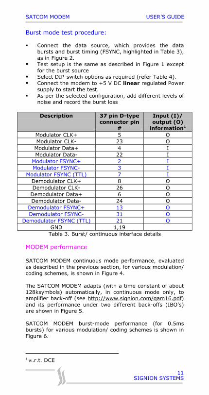
Connect the data source, which provides the databursts and burst timing (FSYNC, highlighted in Table 3),as in Figure 2.
Test setup is the same as described in Figure 1 exceptfor the burst source
Select DIP-switch options as required (refer Table 4). Connect the modem to +5 V DC linear regulated Power
supply to start the test. As per the selected configuration, add different levels of
noise and record the burst loss
Description 37 pin D-typeconnector pin
#
Input (I)/output (O)
information1
Modulator CLK+ 5 OModulator CLK- 23 O
Modulator Data+ 4 IModulator Data- 22 I
Modulator FSYNC+ 2 IModulator FSYNC- 3 I
Modulator FSYNC (TTL) 7 IDemodulator CLK+ 8 ODemodulator CLK- 26 O
Demodulator Data+ 6 ODemodulator Data- 24 O
Demodulator FSYNC+ 13 ODemodulator FSYNC- 31 O
Demodulator FSYNC (TTL) 21 OGND 1,19
Table 3. Burst/ continuous interface details
MODEM performance
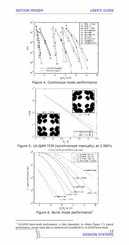
SATCOM MODEM continuous mode performance, evaluatedas described in the previous section, for various modulation/coding schemes, is shown in Figure 4.
The SATCOM MODEM adapts (with a time constant of about128ksymbols) automatically, in continuous mode only, toamplifier back-off (see http://www.signion.com/qam16.pdf)and its performance under two different back-offs (IBO’s)are shown in Figure 5.
SATCOM MODEM burst-mode performance (for 0.5msbursts) for various modulation/ coding schemes is shown inFigure 6.
1 w.r.t. DCE
SATCOM MODEM USER’S GUIDE
SIGNION SYSTEMS
12
Figure 4. Continuous mode performance
Figure 5. 16-QAM TCM (synchronized manually) at 2 IBO’s
Figure 6. Burst mode performance2
2 16-QAM burst-mode performance is data dependent; to obtain Figure 5’s typicalperformance, ensure input data is randomized (scrambled) in 16-QAM burst-mode.
SATCOM MODEM USER’S GUIDE
SIGNION SYSTEMS
13
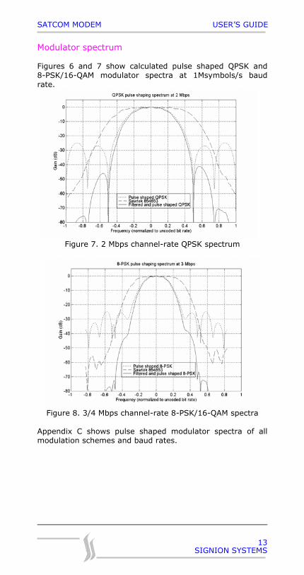
Modulator spectrum
Figures 6 and 7 show calculated pulse shaped QPSK and8-PSK/16-QAM modulator spectra at 1Msymbols/s baudrate.
Figure 7. 2 Mbps channel-rate QPSK spectrum
Figure 8. 3/4 Mbps channel-rate 8-PSK/16-QAM spectra
Appendix C shows pulse shaped modulator spectra of allmodulation schemes and baud rates.
SATCOM MODEM USER’S GUIDE
SIGNION SYSTEMS
14
Configuration details
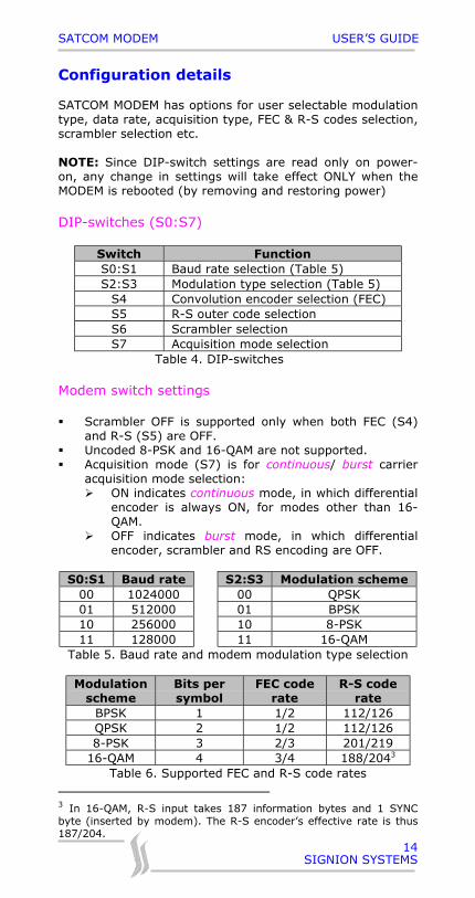
SATCOM MODEM has options for user selectable modulationtype, data rate, acquisition type, FEC & R-S codes selection,scrambler selection etc.
NOTE: Since DIP-switch settings are read only on power-on, any change in settings will take effect ONLY when theMODEM is rebooted (by removing and restoring power)
DIP-switches (S0:S7)
Switch FunctionS0:S1 Baud rate selection (Table 5)S2:S3 Modulation type selection (Table 5)
S4 Convolution encoder selection (FEC)S5 R-S outer code selectionS6 Scrambler selectionS7 Acquisition mode selection
Table 4. DIP-switches
Modem switch settings
Scrambler OFF is supported only when both FEC (S4)and R-S (S5) are OFF.
Uncoded 8-PSK and 16-QAM are not supported. Acquisition mode (S7) is for continuous/ burst carrier
acquisition mode selection: ON indicates continuous mode, in which differential
encoder is always ON, for modes other than 16-QAM.
OFF indicates burst mode, in which differentialencoder, scrambler and RS encoding are OFF.
S0:S1 Baud rate S2:S3 Modulation scheme00 1024000 00 QPSK01 512000 01 BPSK10 256000 10 8-PSK11 128000 11 16-QAM
Table 5. Baud rate and modem modulation type selection
Modulationscheme
Bits persymbol
FEC coderate
R-S coderate
BPSK 1 1/2 112/126QPSK 2 1/2 112/1268-PSK 3 2/3 201/219
16-QAM 4 3/4 188/2043
Table 6. Supported FEC and R-S code rates
3 In 16-QAM, R-S input takes 187 information bytes and 1 SYNCbyte (inserted by modem). The R-S encoder’s effective rate is thus187/204.
SATCOM MODEM USER’S GUIDE
SIGNION SYSTEMS
15
NOTE:• 0 – Switch position is down (OFF)• 1 – Switch position is up (ON)• FEC code rate is applied when FEC switch S4 is ON• RS code rate is applied when R-S switch S5 is ON• In 16-QAM, the trellis decoder locks to one of 0° or
180° and 90° or 270°. The residual 180° phaseambiguity is resolved by the R-S decoder when it failsto acquire its unique word within a timeout period.When R-S is OFF, modem enters a debug mode, wherein user can use the R-S switch as phase-switch, afterstart up, to resolve a potential 180° phase ambiguity(indicated when the DTE fails to synchronize).
Eb/N0 indication
8-bit Eb/N0 is indicated on a 10-pin header (JP1) in 0.25dBsteps over 2.5dB-15dB range. Details of the header are asgiven below:
Pin Description1:8 LSB:MSB in 0.25dB steps9 DVDD (3.3V)10 GND
Table 7. JP1 pin descriptionExample:0x15 = 5.25dBEach data pin can sink a current of 1.2mA (sufficient todrive a 1206 LED).
Constellation plot
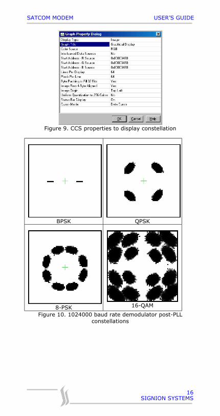
In BPSK/QPSK/8-PSK/16-QAM modulations, with any of theoptional code type chosen, a demodulated constellation(128k baud persistence) of 64x64 pixel resolution may beobtained via the TMS320C6204 DSP’s JTAG port.
Connect Texas Instruments’ JTAG (XDS510, XDS510PP-PLUS, etc.) to TMS320C6204 DSP’s JTAG (JP2) port andthe other end to a PC with Texas Instruments’ C6000Code Composer Studio Software. Switch ‘ON’ theSATCOM MODEM.
To observe the constellation, open the Code ComposerStudio software and abide by the following instructions:
Issue reset command. Debug -> Reset DSP Select View -> Graph -> Image, enter following
properties and click OK. Wait for about a minutefor the display to appear.
Modem data rate = (baud rate)·(bits/symbol)· (FEC code rate)·(R-S code rate)
SATCOM MODEM USER’S GUIDE
SIGNION SYSTEMS
16
Figure 9. CCS properties to display constellation
BPSK QPSK
8-PSK 16-QAM
Figure 10. 1024000 baud rate demodulator post-PLLconstellations
SATCOM MODEM USER’S GUIDE
SIGNION SYSTEMS
17
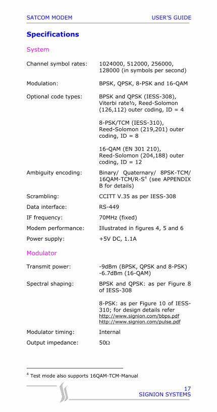
Specifications
System
Channel symbol rates: 1024000, 512000, 256000,128000 (in symbols per second)
Modulation: BPSK, QPSK, 8-PSK and 16-QAM
Optional code types: BPSK and QPSK (IESS-308),Viterbi rate½, Reed-Solomon(126,112) outer coding, ID = 4
8-PSK/TCM (IESS-310),Reed-Solomon (219,201) outercoding, ID = 8
16-QAM (EN 301 210),Reed-Solomon (204,188) outercoding, ID = 12
Ambiguity encoding: Binary/ Quaternary/ 8PSK-TCM/16QAM-TCM/R-S4 (see APPENDIXB for details)
Scrambling: CCITT V.35 as per IESS-308
Data interface: RS-449
IF frequency: 70MHz (fixed)
Modem performance: Illustrated in figures 4, 5 and 6
Power supply: +5V DC, 1.1A
Modulator
Transmit power: -9dBm (BPSK, QPSK and 8-PSK)-6.7dBm (16-QAM)
Spectral shaping: BPSK and QPSK: as per Figure 8of IESS-308
8-PSK: as per Figure 10 of IESS-310; for design details referhttp://www.signion.com/bbps.pdfhttp://www.signion.com/pulse.pdf
Modulator timing: Internal
Output impedance: 50Ω
4 Test mode also supports 16QAM-TCM-Manual
SATCOM MODEM USER’S GUIDE
SIGNION SYSTEMS
18
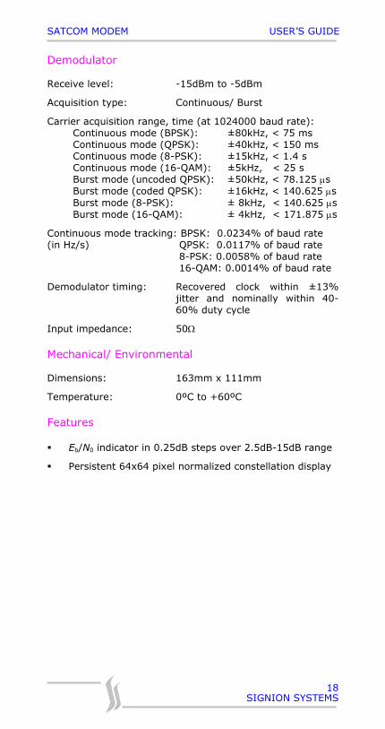
Demodulator
Receive level: -15dBm to -5dBm
Acquisition type: Continuous/ Burst
Carrier acquisition range, time (at 1024000 baud rate):Continuous mode (BPSK): ±80kHz, < 75 msContinuous mode (QPSK): ±40kHz, < 150 msContinuous mode (8-PSK): ±15kHz, < 1.4 sContinuous mode (16-QAM): ±5kHz, < 25 sBurst mode (uncoded QPSK): ±50kHz, < 78.125 µsBurst mode (coded QPSK): ±16kHz, < 140.625 µsBurst mode (8-PSK): ± 8kHz, < 140.625 µsBurst mode (16-QAM): ± 4kHz, < 171.875 µs
Continuous mode tracking: BPSK: 0.0234% of baud rate(in Hz/s) QPSK: 0.0117% of baud rate
8-PSK: 0.0058% of baud rate 16-QAM: 0.0014% of baud rate
Demodulator timing: Recovered clock within ±13%jitter and nominally within 40-60% duty cycle
Input impedance: 50Ω
Mechanical/ Environmental
Dimensions: 163mm x 111mm
Temperature: 0ºC to +60ºC
Features
Eb/N0 indicator in 0.25dB steps over 2.5dB-15dB range
Persistent 64x64 pixel normalized constellation display
SATCOM MODEM USER’S GUIDE
SIGNION SYSTEMS
19
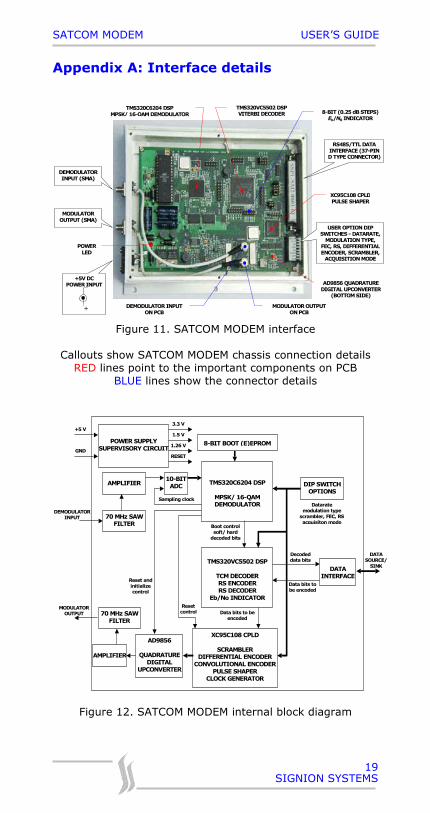
Appendix A: Interface details
MODULATOR OUTPUT (SMA)
DEMODULATOR INPUT (SMA)
RS485/TTL DATA INTERFACE (37-PIN D TYPE CONNECTOR)
TMS320C6204 DSP MPSK/ 16-QAM DEMODULATOR
TMS320VC5502 DSP VITERBI DECODER
XC95C108 CPLDPULSE SHAPER
POWER LED
USER OPTION DIP SWITCHES - DATARATE,
MODULATION TYPE, FEC, RS, DIFFERENTIAL ENCODER, SCRAMBLER,
ACQUISITION MODE
AD9856 QUADRATURE DIGITAL UPCONVERTER
(BOTTOM SIDE)
DEMODULATOR INPUT ON PCB
+5V DC POWER INPUT
+
8-BIT (0.25 dB STEPS) Eb/N0 INDICATOR
MODULATOR OUTPUT ON PCB
Figure 11. SATCOM MODEM interface
Callouts show SATCOM MODEM chassis connection detailsRED lines point to the important components on PCB
BLUE lines show the connector details
DATASOURCE/
SINK
Resetcontrol
70 MHz SAWFILTER
AMPLIFIER10-BITADC TMS320C6204 DSP
MPSK/ 16-QAMDEMODULATOR
Sampling clock
8-BIT BOOT (E)EPROM
TMS320VC5502 DSP
TCM DECODERRS ENCODERRS DECODER
Eb/No INDICATOR
Boot controlsoft/ hard
decoded bits
DIP SWITCHOPTIONS
DATAINTERFACE
Decodeddata bits
Data bits tobe encoded
XC95C108 CPLD
SCRAMBLERDIFFERENTIAL ENCODER
CONVOLUTIONAL ENCODERPULSE SHAPER
CLOCK GENERATOR
Data bits to beencoded
AD9856
QUADRATUREDIGITAL
UPCONVERTER
70 MHz SAWFILTER
AMPLIFIER
Reset andinitializecontrol
POWER SUPPLYSUPERVISORY CIRCUIT
3.3 V
1.5 V
RESET
+5 V
GND
DEMODULATORINPUT
MODULATOROUTPUT
1.26 V
Dataratemodulation type
scrambler, FEC, RSacquisiton mode
Figure 12. SATCOM MODEM internal block diagram
SATCOM MODEM USER’S GUIDE
SIGNION SYSTEMS
20
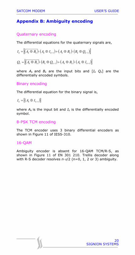
Appendix B: Ambiguity encoding
Quaternary encoding
The differential equations for the quaternary signals are,
( ) ( ) ( ) ( )[ ]11 −− ⊕⋅⊕+⊕⋅⊕= kkkkkkkkk QBBAIABAI
( ) ( ) ( ) ( )[ ]11 −− ⊕⋅⊕+⊕⋅⊕= kkkkkkkkk IABAQBBAQ
where Ak and Bk are the input bits and [Ik Qk] are thedifferentially encoded symbols.
Binary encoding
The differential equation for the binary signal is,
( )[ ]1−⊕= kkk IAI
where Ak is the input bit and Ik is the differentially encodedsymbol.
8-PSK TCM encoding
The TCM encoder uses 3 binary differential encoders asshown in Figure 11 of IESS-310.
16-QAM
Ambiguity encoder is absent for 16-QAM TCM/R-S, asshown in Figure 11 of EN 301 210. Trellis decoder alongwith R-S decoder resolves n·π/2 (n=0, 1, 2 or 3) ambiguity.
SATCOM MODEM USER’S GUIDE
SIGNION SYSTEMS
21
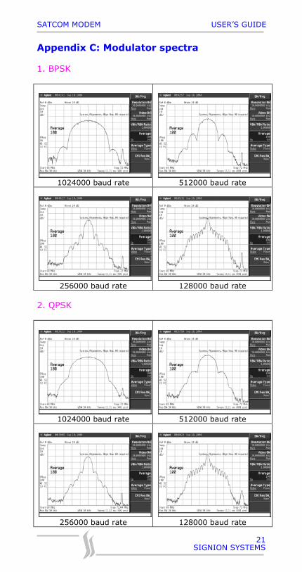
Appendix C: Modulator spectra
1. BPSK
1024000 baud rate 512000 baud rate
256000 baud rate 128000 baud rate
2. QPSK
1024000 baud rate 512000 baud rate
256000 baud rate 128000 baud rate
SATCOM MODEM USER’S GUIDE
SIGNION SYSTEMS
22
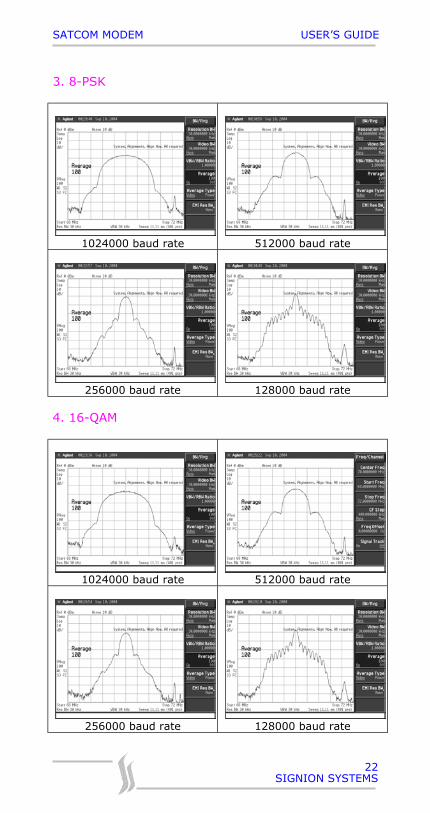
3. 8-PSK
1024000 baud rate 512000 baud rate
256000 baud rate 128000 baud rate
4. 16-QAM
1024000 baud rate 512000 baud rate
256000 baud rate 128000 baud rate
SATCOM MODEM USER’S GUIDE
SIGNION SYSTEMS
23
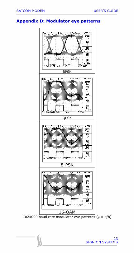
Appendix D: Modulator eye patterns
BPSK
QPSK
8-PSK
16-QAM1024000 baud rate modulator eye patterns (φ = π/8)
SATCOM MODEM USER’S GUIDE
SIGNION SYSTEMS
24
Appendix E: Troubleshooting
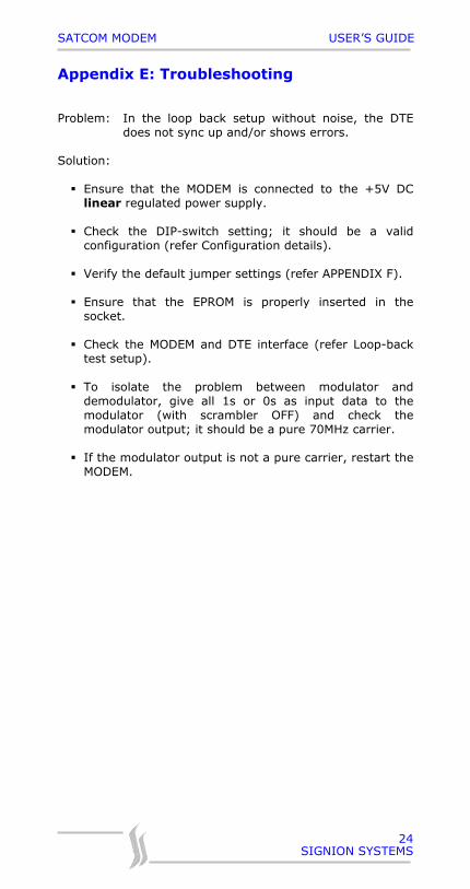
Problem: In the loop back setup without noise, the DTEdoes not sync up and/or shows errors.
Solution:
Ensure that the MODEM is connected to the +5V DClinear regulated power supply.
Check the DIP-switch setting; it should be a validconfiguration (refer Configuration details).
Verify the default jumper settings (refer APPENDIX F).
Ensure that the EPROM is properly inserted in thesocket.
Check the MODEM and DTE interface (refer Loop-backtest setup).
To isolate the problem between modulator anddemodulator, give all 1s or 0s as input data to themodulator (with scrambler OFF) and check themodulator output; it should be a pure 70MHz carrier.
If the modulator output is not a pure carrier, restart theMODEM.
SATCOM MODEM USER’S GUIDE
SIGNION SYSTEMS
25
Appendix F: Default jumper settings
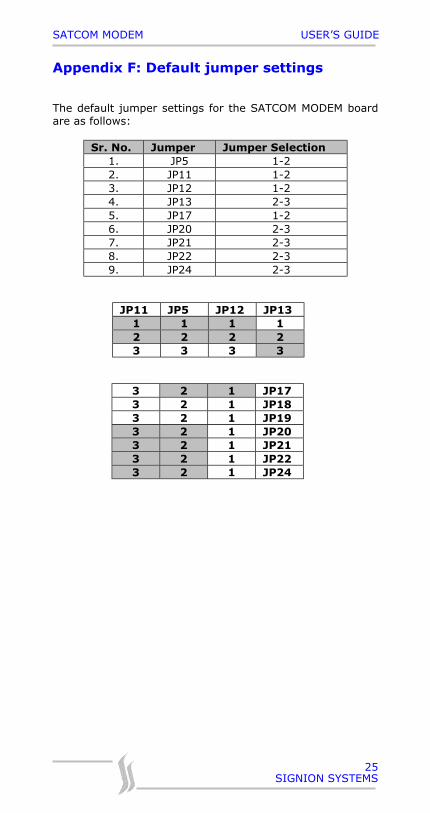
The default jumper settings for the SATCOM MODEM boardare as follows:
Sr. No. Jumper Jumper Selection1. JP5 1-22. JP11 1-23. JP12 1-24. JP13 2-35. JP17 1-26. JP20 2-37. JP21 2-38. JP22 2-39. JP24 2-3
JP11 JP5 JP12 JP131 1 1 12 2 2 23 3 3 3
3 2 1 JP173 2 1 JP183 2 1 JP193 2 1 JP203 2 1 JP213 2 1 JP223 2 1 JP24
SATCOM MODEM USER’S GUIDE
SIGNION SYSTEMS
26
NOTES

SATCOM MODEM USER’S GUIDE
SIGNION SYSTEMS
27


![[Modem ADSL D-Link DSL-500B] Ip, Login e Senha _ Modem Tutoriais](https://img.document.onl/doc/110x75/5571fa8f4979599169928266/modem-adsl-d-link-dsl-500b-ip-login-e-senha-modem-tutoriais.jpg)