Embed Size (px)
Citation preview
Rui Pedro de Magalhães Claro Prior
Scalable Network Architectures
Supporting Quality of Service
Tese submetida à Faculdade de Ciências da Universidade do Porto
para obtenção do grau de Doutor em Ciência de Computadores
Departamento de Ciência de Computadores
Faculdade de Ciências da Universidade do Porto
2007


3
To my parents, who gave me life,
and to my wife, who gives it a meaning


5
ACKNOWLEDGMENTS
First and foremost, I would like to express my deepest gratitude to my advisor, Susana
Sargento, not only for her support, encouragement and guidance, but also for her patience and
availability and, above all, her friendship. I am also grateful to my co-advisor, Prof. Miguel
Filgueiras, without whom I would not be able to finish this work.
To my friend Clara Magalhães, thank you very much for the French translation of the
Abstract — my French would not be enough to write a proper Résumé.
To my colleagues Pedro Brandão and Sérgio Crisóstomo, I want to express my sincere
gratitude for all the interesting discussions and, especially, for their true friendship.
I would like to thank Ana Paula Tomás and João Pedro Pedroso for some useful suggestions
regarding the work in chapter 8 and for helping me get started with the optimization software.
I would also like to thank all members of the Computer Science Department for allowing me
two and a half years of exclusive dedication to the PhD.
Finally, I want to thank my wife, Mari Carmen, for all her love, affection and understanding,
and my wonderful family, to whom I owe everything I am.

7
ABSTRACT
The realization of the advantages of packet switching networks over their circuit-
switching counterparts (efficiency, resilience, flexibility) and the economical benefits of
providing multiple services over a single network infrastructure has spawned great interest in
the introduction of new services in the Internet. However, many of these services have
stringent Quality of Service requirements that the Internet was not designed to meet. The
satisfactory support of these services over the Internet is, therefore, conditioned by its ability
to provide good end-to-end QoS to the network flows, but there are technical issues in doing
it at the Internet scale. This thesis deals with the problems associated with providing end-to-
end QoS to individual flows in a scalable way.
The thesis is divided into two parts. The first part concerns distributed models for
scalable QoS provisioning in the Internet, where network routers perform both data plane and
control plane tasks without recourse to centralized, off-path control entities. We evaluate the
RSVP Reservation Aggregation model, an IETF proposed standard for scalable provisioning
of end-to-end QoS to individual flows, and define a resource management policy for use with
this model. We also propose a new approach, the Scalable Reservation-Based QoS (SRBQ)
architecture, based on flow aggregation on the data plane and on a scalable model of per-flow
signaling on the control plane. An evaluation of SRBQ shows that it provides good QoS
metrics with higher network utilization than RSVP Aggregation.
The second part of the thesis proposes an architecture for the QoS subsystem of a
next-generation, IP-based mobile telecommunications system, based on centralized control
entities, designated QoS brokers. Our proposal uses a layered resource management model,
tackling the aspects of QoS control in the access, in the core, and in the inter-domain path
segments. We propose three scenarios for the interaction of the different entities with the QoS
brokers and three corresponding strategies for coordination between application signaling and

8
network resource reservation signaling. These different strategies allow for the customization
of service deployment in different use cases. We also propose several optimizations to the
joint use of the Session Initiation Protocol (SIP) and Mobile IPv6, improving the efficiency of
pre-session mobility. Finally, we propose a method for inter-domain QoS routing based on
virtual trunks. We define an extension to the Border Gateway Protocol (BGP) for the transport
of QoS metrics and their use in the path selection process. Resorting to simulation, our
proposal is evaluated and compared to a competing proposal and to the optimal solution
centrally obtained using Integer Linear Programming.
9
RESUMO
A percepção das vantagens das redes de comutação de pacotes em relação às de
comutação de circuitos (eficiência, robustez, flexibilidade) e das vantagens económicas do
fornecimento de múltiplos serviços sobre uma infra-estrutura de rede única tem gerado um
grande interesse na introdução de novos serviços na Internet. Contudo, muitos destes serviços
têm requisitos rígidos de Qualidade de Serviço (QoS) que a Internet não foi concebida para
satisfazer. O suporte de forma satisfatória destes serviços está, portanto, condicionado pela
capacidade de garantir uma boa QoS aos fluxos na rede, mas há problemas técnicos em fazê-
lo à escala da Internet. Esta tese aborda os problemas associados ao suporte de QoS extremo a
extremo em fluxos individuais de forma escalável.
A tese divide-se em duas partes. A primeira parte concerne modelos distribuídos para
o fornecimento de QoS na Internet, em que os routers da rede realizam tarefas tanto do plano
de dados como do plano de controlo sem recurso a entidades centrais fora do percurso dos
dados. É avaliado o modelo de Agregação de Reservas RSVP, uma norma proposta pelo
organismo IETF para o fornecimento escalável de QoS extremo a extremo a fluxos
individuais, e é definida uma política de gestão de recursos para usar neste modelo. Também é
proposta uma nova aproximação, a arquitectura Scalable Reservation-Based QoS (SRBQ),
baseada na agregação de fluxos no plano de dados e num modelo escalável de sinalização por
fluxo no plano de controlo. A avaliação do SRBQ mostra que este modelo fornece bons
valores de QoS, com uma utilização mais elevada dos recursos de rede que a Agregação
RSVP.
A segunda parte da tese propõe uma arquitectura para o subsistema de QoS de um
sistema de telecomunicações móveis da próxima geração baseado em IP, que se baseia em
entidades de controlo centralizadas, designadas mediadores de QoS. A proposta usa um
modelo por camadas para a gestão de recursos, solucionando os aspectos de controlo de QoS
10
nos segmentos de acesso, de core, e inter-domínio do caminho. São propostos três cenários
para a interacção das diferentes entidades com os mediadores de QoS e três estratégias
correspondentes para a coordenação entre a sinalização de aplicação e a de reserva de
recursos de rede. Estas diferentes estratégias permitem a adaptação do fornecimento dos
serviços a diferentes casos de uso. Também se propõe um conjunto de optimizações no uso
conjunto do Session Initiation Protocol (SIP) e do Mobile IPv6 que melhoram a eficiência da
mobilidade pré-sessão. Por fim, propõe-se um método para o encaminhamento inter-domínio
baseado em QoS usando virtual trunks. É definida uma extensão ao Border Gateway Protocol
(BGP) para o transporte de medidas de QoS e para o seu uso no processo de selecção de
caminhos. Recorrendo à simulação, avalia-se a proposta e comparam-se os resultados com os
de uma proposta concorrente e com os valores óptimos obtidos de forma centralizada
recorrendo a Programação Linear Inteira.
11
RÉSUMÉ
La prise de conscience des avantages des réseaux de commutation de paquets
comparés aux réseaux de commutation de circuits (plus efficaces, robustes et flexibles) ainsi
que les avantages économiques des multiples services fournis sur une infrastructure de réseau
unique, suscite un intérêt pour l’introduction de nouveaux services sur Internet. Néanmoins,
beaucoup de ces services ont des exigences très fortes de Qualité de Service (QoS) auxquelles
Internet n’était pas préparé à répondre. Ainsi, la fourniture satisfaisante de ces services sur
Internet est conditionnée par sa capacité à garantir une bonne qualité de service de bout en
bout aux flux du réseau, mais il existe des problèmes techniques pour le faire à l’échelle
d’Internet. Cette thèse aborde les problèmes associés à la fourniture d’une QoS de bout en
bout en flux distincts de manière scalable.
La thèse se divise en 2 parties. La première partie concerne les modèles distribués
permettant de fournir une QoS scalable sur Internet, où les routeurs du réseau réalisent des
tâches sur le plan des données et du contrôle sans recourir à des entités centrales de contrôle
hors parcours des données. Le modèle évalué est celui de l’Agrégation de Réserve RSVP, une
norme proposée par l’organisme IETF pour la fourniture scalable de QoS de bout en bout aux
flux distincts, et une politique de gestion des ressources a été définie pour utiliser ce modèle.
Une nouvelle approche est également présentée, l’architecture Scalable Reservation-Based
QoS (SRBQ), basée sur l’agrégation de flux au niveau des données et sur un modèle scalable
de signalisation par flot au niveau du contrôle. L’évaluation du SRBQ montre que ce modèle
fournit de bons résultats de QoS, avec une utilisation plus élevée des ressources du réseau que
l’Agrégation RSVP.
La deuxième partie de cette thèse propose une architecture pour les sous-systèmes de
QoS d’un système de télécommunication mobile de nouvelle génération basée sur IP, qui
utilise l’idée des entités de contrôles centralisés, appelées médiateurs de QoS. Cette

12
proposition utilise un modèle de gestion de ressources par couches, traitant les aspects de
contrôle de QoS au niveau des segments d’accès, core et inter-domaine du chemin. Nous
proposons trois scénarios pour l’interaction des différentes entités avec les médiateurs de QoS
et trois stratégies correspondantes pour la coordination entre la signalisation de l’application
et de la réserve des ressources réseau. Ces différentes stratégies permettent l’adaptation du
déploiement des services à différents cas d’utilisation. Nous présentons aussi plusieurs
optimisations pour l’utilisation conjointe du Session Initiation Protocol (SIP) et du Mobile
IPv6, qui améliore l’efficacité de la mobilité de la pré-session. Enfin, nous proposons une
méthode de routage de QoS inter-domaine en utilisant virtual trunks. Nous avons défini une
extension au Border Gateway Protocol (BGP) pour le transport des mesures de QoS et pour
leur utilisation dans le processus de sélection de chemin. En utilisant des processus de
simulation, la solution est évaluée et comparée avec une proposition concurrente et avec la
solution optimale centralement obtenue en utilisant la Programmation Linéaire Entière.
13
CONTENTS
Acknowledgments .................................................................................................... 5
Abstract ..................................................................................................................... 7
Resumo...................................................................................................................... 9
Résumé .................................................................................................................... 11
Contents .................................................................................................................. 13
List of Figures ......................................................................................................... 17
Acronyms and Symbols ......................................................................................... 21
Chapter 1 Introduction......................................................................................... 27
1.1 Main Contributions ............................................................................................................29
1.2 Publications .........................................................................................................................30 1.2.1 Journals, Book Series and Books .....................................................................................30 1.2.2 International Proceedings with Independent Reviewing ..................................................31 1.2.3 National Proceedings with Independent Reviewing.........................................................32 1.2.4 Pending.............................................................................................................................32 1.2.5 Technical Reports.............................................................................................................32
1.3 Organization........................................................................................................................33
Chapter 2 Related work ....................................................................................... 37
2.1 Building Blocks for a QoS Framework.............................................................................38 2.1.1 Packet Classification ........................................................................................................38 2.1.2 Queuing/Scheduling .........................................................................................................38 2.1.3 Metering ...........................................................................................................................39 2.1.4 Traffic Shaping.................................................................................................................39 2.1.5 Traffic Policing ................................................................................................................39 2.1.6 Packet Marking ................................................................................................................40 2.1.7 Admission Control ...........................................................................................................40 2.1.8 Signaling...........................................................................................................................40
14 CONTENTS
2.2 Main IETF Frameworks for QoS ..................................................................................... 41 2.2.1 IntServ.............................................................................................................................. 41 2.2.2 DiffServ ........................................................................................................................... 47
2.3 Other QoS Models.............................................................................................................. 51 2.3.1 Alternative Signaling ....................................................................................................... 51 2.3.2 Aggregation-based schemes............................................................................................. 53 2.3.3 Elimination of State in the Core....................................................................................... 56 2.3.4 Bandwidth Brokers .......................................................................................................... 61
2.4 Inter-Domain QoS.............................................................................................................. 64 2.4.1 Inter-Domain Resource Reservation................................................................................ 65 2.4.2 Inter-Domain QoS Routing.............................................................................................. 67
2.5 QoS in IP-Based Mobile Telecommunication Systems ................................................... 70 2.5.1 UMTS .............................................................................................................................. 70 2.5.2 Next Generation IP-Based Mobile Networks .................................................................. 73
2.6 SIP — Session Initiation Protocol..................................................................................... 75 2.6.1 Protocol Overview ........................................................................................................... 75 2.6.2 Integration with QoS Signaling — Preconditions............................................................ 78 2.6.3 SIP and Mobility .............................................................................................................. 79
2.7 Summary............................................................................................................................. 80
Chapter 3 Evaluation of RSVP Reservation Aggregation................................. 81
3.1 Overview of RSVP Reservation Aggregation .................................................................. 82
3.2 Implemented Solution........................................................................................................ 84 3.2.1 Message Processing ......................................................................................................... 84 3.2.2 Aggregate Bandwidth Policy ........................................................................................... 87 3.2.3 Particularities and Limitations ......................................................................................... 88
3.3 Performance Analysis ........................................................................................................ 91 3.3.1 Variable Bulk Size ........................................................................................................... 93 3.3.2 Variable Offered Load ..................................................................................................... 95 3.3.3 Variable Hysteresis Time................................................................................................. 96 3.3.4 Variable Offered Load Rotation Time............................................................................. 97
3.4 Conclusions ......................................................................................................................... 98
Chapter 4 Scalable Reservation-Based QoS ..................................................... 99
4.1 SRBQ Architecture Overview......................................................................................... 100
4.2 SRBQ Architecture Details ............................................................................................. 102 4.2.1 Service Differentiation and Traffic Control................................................................... 102 4.2.2 Label Mechanism........................................................................................................... 106 4.2.3 Signaling Protocol.......................................................................................................... 108 4.2.4 Packet Processing .......................................................................................................... 115 4.2.5 Soft Reservations and Efficient Timer Implementation ................................................ 116
4.3 Performance Evaluation.................................................................................................. 117 4.3.1 End-to-End QoS Guarantees.......................................................................................... 119 4.3.2 Independence between Flows ........................................................................................ 124
CONTENTS 15
4.3.3 Real Multimedia Streams ...............................................................................................126 4.3.4 Scalability.......................................................................................................................129
4.4 Comparison between SRBQ and RSVPRAgg................................................................131 4.4.1 Qualitative Comparison..................................................................................................131 4.4.2 Quantitative Comparison................................................................................................133
4.5 Conclusions........................................................................................................................141
Chapter 5 DAIDALOS Approach to Quality of Service.................................... 143
5.1 The DAIDALOS Project ..................................................................................................144
5.2 DAIDALOS Architecture ................................................................................................147
5.3 QoS Subsystem Overview ................................................................................................150 5.3.1 Comparison with UMTS ................................................................................................153
5.4 End-to-End QoS Control .................................................................................................154 5.4.1 Per-Flow QoS — Session Setup.....................................................................................155 5.4.2 Intra-Domain QoS Control.............................................................................................156 5.4.3 Inter-Domain QoS Control.............................................................................................158
5.5 Summary ...........................................................................................................................159
Chapter 6 Session and Resource Reservation Signaling............................... 161
6.1 Session Initiation...............................................................................................................162 6.1.1 MT Scenario ...................................................................................................................162 6.1.2 MMSP Scenario .............................................................................................................164 6.1.3 ARM Scenario................................................................................................................165 6.1.4 Comparison of the Scenarios..........................................................................................166
6.2 Mobility..............................................................................................................................168
6.3 Simulation Results ............................................................................................................172
6.4 Conclusions........................................................................................................................183
Chapter 7 Mobility Optimization ....................................................................... 185
7.1 Inefficiency of SIP with MIPv6 .......................................................................................186 7.1.1 Note on the Use of Binding Requests ............................................................................189
7.2 Optimizing the Use of SIP with MIPv6...........................................................................190 7.2.1 Inclusion of CoA Information in SDP(ng) .....................................................................191 7.2.2 Optimized Initiation Sequence .......................................................................................192
7.3 SIP Registration................................................................................................................194
7.4 Issues with Dormancy/Paging..........................................................................................195
7.5 Delay Analysis ...................................................................................................................195 7.5.1 Standard Case.................................................................................................................196 7.5.2 Optimized Case ..............................................................................................................197 7.5.3 Comparison ....................................................................................................................197
7.6 Simulation Results ............................................................................................................198
7.7 Conclusions........................................................................................................................201
16 CONTENTS
Chapter 8 Inter-domain QoS ............................................................................. 203
8.1 Inter-Domain QoS Routing with Virtual Trunks.......................................................... 204 8.1.1 Virtual Trunk Model of the Autonomous Systems........................................................ 204 8.1.2 Problem Statement ......................................................................................................... 206 8.1.3 Problem Statement Transform ....................................................................................... 206 8.1.4 Problem Formulation in ILP .......................................................................................... 210 8.1.5 Variant Formulation....................................................................................................... 214
8.2 Proposed Protocol and Associated Algorithms.............................................................. 215 8.2.1 QoS Routing .................................................................................................................. 215
8.3 Simulation Results............................................................................................................ 219 8.3.1 Simulated Scenario ........................................................................................................ 220 8.3.2 Link Usage, Route Optimality and QoS Parameters...................................................... 221 8.3.3 Signaling Overhead and Route Stability........................................................................ 224
8.4 Conclusions ....................................................................................................................... 226
Chapter 9 Conclusions ...................................................................................... 229
9.1 Thesis Summary ............................................................................................................... 229
9.2 Topics for Further Research ........................................................................................... 233
Appendix A Admission Control ........................................................................ 235
Bibliography .......................................................................................................... 237
17
LIST OF FIGURES
Figure 2.1: Token bucket traffic specification...................................................................................................43
Figure 2.2: RSVP messages.................................................................................................................................46
Figure 2.3: Packet classification and traffic conditioning functions of a DiffServ edge node .......................49
Figure 2.4: IntServ over DiffServ — sample network configuration ..............................................................54
Figure 2.5: SRP packet processing by routers...................................................................................................58
Figure 2.6: BGRP signaling and sink tree aggregation ....................................................................................66
Figure 2.7: Packet-switched domain of the UMTS architecture (with IMS)..................................................72
Figure 2.8: UMTS protocol stack .......................................................................................................................72
Figure 2.9: Session initiation with SIP ...............................................................................................................77
Figure 2.10: Integration of SIP and resource reservation using preconditions (example) ............................78
Figure 3.1: Simplest case — the aggregate may accommodate the new flow. ................................................84
Figure 3.2: Aggregate exists, but has insufficient bandwidth ..........................................................................85
Figure 3.3: The aggregate does not exist............................................................................................................86
Figure 3.4: Aggregate bandwidth management ................................................................................................87
Figure 3.5: Loss of ResvConf problem...............................................................................................................89
Figure 3.6: Simulation topology for the evaluation of RSVP Reservation Aggregation................................91
Figure 3.7: Simulation results with variable bulk size......................................................................................94
Figure 3.8: Simulation results with variable offered load ................................................................................95
Figure 3.9: Simulation results with variable hysteresis time ...........................................................................97
Figure 3.10: Simulation results with variable offered load rotation time .......................................................97
Figure 4.1: Architecture overview....................................................................................................................100
Figure 4.2: Queuing model................................................................................................................................103
Figure 4.3: Newly defined objects.....................................................................................................................109
Figure 4.4: Message flow ...................................................................................................................................113
Figure 4.5: Route change...................................................................................................................................114
Figure 4.6: Relative weight of refresh messages..............................................................................................117
Figure 4.7: Topology used for SRBQ evaluation.............................................................................................118
Figure 4.8: QoS and per-class utilization results with varying offered CL load ..........................................121
Figure 4.9: QoS and per-class utilization results with varying offered GS load ..........................................122
18 LIST OF FIGURES
Figure 4.10: QoS and per-class utilization results with varying reserved rates for CL flows .................... 123
Figure 4.11: Delay and packet losses with varying burstiness of misbehaved flows.................................... 126
Figure 4.12: QoS and utilization results with varying offered loads using real video flows ....................... 128
Figure 4.13: Average processing delay of SResv messages ............................................................................ 130
Figure 4.14: QoS and performance results of SRBQ, RSVPRAgg and RSVP with varying offered load
factor, and the same type of traffic flows............................................................................................... 135
Figure 4.15: QoS and utilization results of SRBQ and RSVPRAgg with varying CL load factor, and
several types of traffic flows.................................................................................................................... 138
Figure 4.16: Delay and packet losses of SRBQ and RSVPRAgg with varying burstiness of misbehaved
flows .......................................................................................................................................................... 140
Figure 5.1: Overall DAIDALOS architecture................................................................................................. 147
Figure 5.2: Network architecture (QoS-related subset) ................................................................................. 151
Figure 5.3: Admission control in the inter-domain call scenario .................................................................. 155
Figure 5.4: Resource management in the core network................................................................................. 157
Figure 5.5: Inter-domain QoS control — signaling........................................................................................ 158
Figure 6.1: SIP session initiation — MT scenario .......................................................................................... 162
Figure 6.2: Legacy, QoS-unaware session initiation — MT scenario ........................................................... 163
Figure 6.3: SIP session initiation — MMSP scenario..................................................................................... 164
Figure 6.4: SIP session initiation — ARM scenario ....................................................................................... 165
Figure 6.5: Legacy, QoS-unaware session initiation — ARM scenario ........................................................ 166
Figure 6.6: Fast handover process ................................................................................................................... 169
Figure 6.7: Intra-domain, inter-AN handover — MT scenario .................................................................... 170
Figure 6.8: Inter-domain handover between federated domains .................................................................. 171
Figure 6.9: Simulated message sequences — MMSP scenario ...................................................................... 173
Figure 6.10: Simulated message sequences — ARM scenario....................................................................... 174
Figure 6.11: Simulated message sequences — MT scenario.......................................................................... 175
Figure 6.12: Topology used in the QoS signaling simulations ....................................................................... 176
Figure 6.13: Successful session setup delay ..................................................................................................... 177
Figure 6.14: Rejected call setup delay ............................................................................................................. 178
Figure 6.15: Call termination delay ................................................................................................................. 179
Figure 6.16: Call setup delay CDF (rrnn, 70 calls/s)....................................................................................... 180
Figure 6.17: Percentile 99 call setup delay with variable signaling load ...................................................... 180
Figure 6.18: System response under a peak of new calls ............................................................................... 181
Figure 6.19: Peak of new calls — varying steady-state load.......................................................................... 182
Figure 6.20: Recovery time from the peak of calls (200/s for 5s) .................................................................. 183
Figure 7.1: Inter-domain call without optimization (both terminals roaming) ........................................... 187
Figure 7.2: Optimized inter-domain call (both terminals roaming) ............................................................. 193
Figure 7.3: Registration procedure.................................................................................................................. 194
Figure 7.4: Dial-to-ringtone delay with varying inter-domain delay ............................................................ 198
Figure 7.5: Call setup delay with varying inter-domain link propagation delay......................................... 199
Figure 7.6: Call setup delay with varying loss probability in the wireless links .......................................... 200
LIST OF FIGURES 19
Figure 8.1: Virtual trunk type SLSs.................................................................................................................205
Figure 8.2: Simple network with 4 nodes.........................................................................................................207
Figure 8.3: Cyclic network with 5 nodes..........................................................................................................208
Figure 8.4: Propagation of metrics in the QoS_INFO attribute ....................................................................217
Figure 8.5: Route comparison/selection function............................................................................................218
Figure 8.6: Topology and traffic distribution..................................................................................................220
Figure 8.7: Offered traffic distribution............................................................................................................221
Figure 8.8: Percentage of routes with loss probability ≤ X ............................................................................222
Figure 8.9: Percentage of routes with delay ≤ X..............................................................................................223
Figure 8.10 - Distribution of the number of updates per second in ASs .......................................................224
Figure 8.11 - Route stability vs. alarm level thresholds..................................................................................225
Figure 8.12 - Frequency of BGP updates.........................................................................................................225

21
ACRONYMS AND SYMBOLS
3GPP Third Generation Partnership Project
3G Third Generation (mobile telecommunication systems)
4G Fourth Generation (also referred to as B3G or NGN)
A4C Authentication, Authorization, Accounting, Auditing and Charging
AAAC Authentication, Authorization, Accounting and Charging
AAL ATM Adaptation Layer
ACM Association for Computing Machinery
AD Administrative Domain
AF Assured Forwarding
AN Access Network
AoR Address of Record
API Application Programming Interface
AQM Active Queue Management
AR Access Router
ARM Advanced Router Mechanisms
ARPANET Advanced Research Projects Agency Network
AS Autonomous System
ATM Asynchronous Transfer Mode
B3G Beyond 3G
BA Behavior Aggregate
BB Bandwidth Broker
BGP Border Gateway Protocol
BGRP Border Gateway Reservation Protocol
BReq Binding Request
22 ACRONYMS AND SYMBOLS
BR Binding Response
BRR Binding Refresh Request
BQ Binding Query
CJVC Core Jitter Virtual Clock
CL Controlled Load
CoA Care-of Address
CoT Care-of Test
CoTI Care-of Test Init
CPU Central Processing Unit
CS Circuit-Switched
CSCF Call Session Control Function
CT Context Transfer
DCCP Datagram Congestion Control Protocol
DiffServ Differentiated Services
DSCP Differentiated Services Code Point
DNS Domain Name Service
DoS Denial of Service
DPS Dynamic Packet State
DRR Deficit Round-Robin
DS Differentiated Services
DV Distance Vector
DVB Digital Video Broadcasting
DVB-H Digital Video Broadcasting — Handheld
DVB-S Digital Video Broadcasting — Satellite
DVB-T Digital Video Broadcasting — Terrestrial
DWDM Dense Wavelength Division Multiplexing
DWRR Deficit Weighted Round-Robin (same as DRR)
EF Expedited Forwarding
EoIP Everything over IP
ER Edge Router
FHO Fast Handover
FIFO First In, First Out
FTP File Transfer Protocol
GGSN Gateway GPRS Support Node
ACRONYMS AND SYMBOLS 23
GIST General Internet Signaling Transport
GLB Greatest Lower Bound
GPRS General Packet Radio Service
GS Guaranteed Service
GSM Global System for Mobile Communications
GTP GPRS Tunneling Protocol
HA Home Agent
HKT Home Keygen Token
HoA Home Address
HoT Home Test
HoTI Home Test Init
HSPA High Speed Packet Access
HSPDA High Speed Packet Downlink Access
HSPUA High Speed Packet Uplink Access
HSS Home Subscriber Server
HTTP Hypertext Transfer Protocol
iBGP Internal BGP
ICMP Internet Control Message Protocol
I-CSCF Interrogating Call Session Control Function
IEEE Institute of Electrical and Electronics Engineers
IETF Internet Engineering Task Force
IKE Internet Key Exchange Protocol
IMS IP Multimedia Subsystem
IntServ Integrated Services
IP Internet Protocol
ISP Internet Service Provider
ITU-T International Telecommunication Union — Telecommunication
Standardization Sector
JVC Jitter Virtual Clock
LAN Local Area Network
l-QC Local QoS Class
LS Link State
LSP Label-Switched Path
LUB Least Upper Bound
24 ACRONYMS AND SYMBOLS
MARQS Mobility Management, AAA, Resource Management, QoS and Security
MBAC Measurement-Based Admission Control
MGW Media Gateway
MIME Multipurpose Internet Mail Extensions
MMSP Multimedia Service Proxy (also Multimedia Service Platform)
MN Mobile Node
MPLS Multiprotocol Label Switching
MQC Meta QoS Class
MS Measured Sum
MSC Message Sequence Chart; also Mobile Switching Center (in UMTS)
MT Mobile Terminal
MTU Maximum Transmission Unit
NAI Network Access Identifier
NAPTR Naming Authority Pointer (DNS)
NAT Network Address Translation
NGN Next Generation Network
NSIS Next Steps in Signaling
NSLP NSIS Signaling Layer Protocol
NTLP NSIS Transport Layer Protocol
NVUP Network View of the User Profile
OSPF Open Shortest Path First
PBAC Parameter-Based Admission Control (also Probe-Based Admission Control)
PC Paging Controller
P-CSCF Proxy Call Session Control Function
PDP Policy Decision Point
PEP Policy Enforcement Point
PHB Per-Hop Behavior
PRNG Pseudo-Random Number Generator
PSTN Public Switched Telephone Network
q-BGP QoS-enhanced BGP
QoS Quality of Service
RAM Random Access Memory
RAN Radio Access Network
RED Random Early Detection
ACRONYMS AND SYMBOLS 25
RIO Random Early Detection with In/Out Bit
RRP Return Routability Procedure
RSVP Resource Reservation Protocol
RSVPRAgg RSVP Reservation Aggregation
RTCP Real-Time Control Protocol
RTP Real-Time Protocol
RTT Round Trip Time
SCORE Stateless Core
S-CSCF Serving Call Session Control Function
SCTP Stream Control Transmission Protocol
SDP Session Description Protocol
SDPng Session Description Protocol — New Generation
SGSN Serving GPRS Support Node
SIB Seamless Integration of Broadcast
SIP Session Initiation Protocol
SR Subdomain Router
SRBQ Scalable Reservation-Based QoS
SRV Service Record (DNS)
SS7 Signaling System #7
SVUP Service View of the User Profile
TCP Transmission Control Protocol
TD-CDMA Time Division — Code Division Multiple Access
TSC Time Stamp Counter
UA User Agent (SIP)
UDP User Datagram Protocol
URI Uniform Resource Identifier
URL Uniform Resource Locator
USP Ubiquitous and Seamless Pervasiveness
UTRAN UMTS Terrestrial Radio Access Network
VC Virtual Clock
VID Virtual Identity (also Virtual Identifier)
VLL Virtual Leased Line
VoIP Voice over IP
VQ Virtual Queues

26 ACRONYMS AND SYMBOLS
WCDMA Wideband Code Division Multiple Access
WFQ Weighted Fair Queuing
WiFi Wireless Fidelity (IEEE 802.11)
WiMax Worldwide Interoperability for Microwave Access (IEEE 802.16)
WRR Weighted Round-Robin
YESSIR Yet Another Sender Session Internet Reservation Protocol
27
CHAPTER 1
INTRODUCTION
The Holy Grail of computer networking is to design a network that has the flexibility
and low cost of the Internet, yet offers the end-to-end quality of service guarantees of the
telephone network.
S. Keshav
Having its roots in the military ARPANET, conceived as a data transport network with
a focus on resilience, the Internet supports only a best effort service model, where all packets
are treated the same way, therefore providing a single level of service. Now that the Internet is
becoming the ubiquitous global communication infrastructure, new applications are emerging
with more demanding and diversified requirements than data transport. Internet telephony, for
example, has much stricter delay requirements than remote terminal, the most demanding of
the original applications. The deployment of other service models providing better Quality of
Service (QoS) than best effort is of great importance for the transport of these new
applications.
Recommendation E.800 of the ITU-T [ITU-TE.800] has defined QoS as “the
collective effect of service performance, which determines the degree of satisfaction of a user
of the service.” Notwithstanding the intrinsically subjective nature of the concept, QoS in
packet switching networks may be ascertained through a number of objective network
28 CHAPTER 1 INTRODUCTION
performance metrics. The most relevant metrics for QoS are the packet delay, delay variation
(jitter), throughput and packet loss ratio.
For most practical purposes, the generous amounts of capacity made possible by
recent technological advances (particularly in the optical link technologies used in the
backbones) provide good QoS parameters to the applications as long as the utilization remains
low. The main objective of QoS provisioning models is, therefore, to provide guarantees
regarding those parameters, ensuring they remain adequate for the applications’ requirements
even when the network load increases, giving rise to congestion. Although adding more
capacity to the network may alleviate the effects of congestion, in the long term the extra
capacity will end up being used, making overprovisioning more of a band-aid than an actual
solution to the QoS problem — a true solution must not only provide good QoS parameters,
but also provide guarantees that make them predictable and dependable.
Aiming at the introduction of QoS support in the Internet, the IETF has proposed two
major frameworks: Integrated Services (IntServ) and Differentiated Services (DiffServ). The
IntServ architecture was the first one to emerge. Based on per-flow reservations subject to
admission control, IntServ provides service classes with both strict and soft QoS guarantees.
IntServ’s strengths lie in its capability of providing both strict QoS guarantees and adequately
efficient resource usage (particularly in the case of multicast flows). However, IntServ is
fundamentally flawed regarding scalability: the need to implement complex packet scheduling
algorithms and to classify every packet based on both layer 3 and layer 4 header information
is unbearable to high-performance routers in core networks. Moreover, the use of RSVP
signaling for reserving resources and maintaining per-flow state does not scale to a very large
number of simultaneous flows. The DiffServ architecture emerged as a scalable alternative to
IntServ that does not suffer from scalability problems: there is no per-flow resource
reservation, flows are aggregated in classes according to specific characteristics, and service
differentiation is performed based on the service class to which each packet belongs. The
drawback of DiffServ is that without flow admission control mechanisms, traffic within a
class may exceed the amount supported by the provisioned resources, degrading the QoS
received by flows in that class due to cross-interaction either at the packet schedulers or at the
edge traffic conditioners.
This thesis deals with the problems associated with providing end-to-end QoS to
individual flows in a scalable way while maintaining good usage of the network resources,
conciliating the benefits of the IntServ and DiffServ architectures. The text is divided into two
parts. The first part deals with distributed approaches, where the network routers cooperate
1.1 MAIN CONTRIBUTIONS 29
among themselves to perform not only the data plane functions (e.g., packet scheduling)
necessary for providing QoS guarantees, but also the control plane functions (e.g., resource
reservation signaling). We evaluate an existing model, based on the aggregation of RSVP
reservations inside a network domain, and propose a new one, designated Scalable
Reservation-Based QoS (SRBQ), based on flow aggregation on the data plane and on a
scalable model of per-flow signaling on the control plane. In the second part of the thesis we
propose an architecture for the QoS subsystem of a next generation IP-based mobile
telecommunications system, supporting not only SIP-based multimedia applications, but also
all kinds of IP-based applications, including legacy ones. In this architecture, QoS control is
segmented, and control plane functions are centralized at entities designated QoS Brokers. We
address several issues, mostly related to signaling, and propose a model for inter-domain QoS
routing. The work described in this second part of the thesis was developed in the scope of the
DAIDALOS Integrated Project (IST-2002-506997) in the Thematic Priority “Information
Society Technologies” of EU Framework Programme 6 for Research and Development.
1.1 Main Contributions
The main contributions of this thesis to the state of the art are the following:
• An analysis of the RSVP Reservation Aggregation model proposed in [RFC3175] and the
proposal of a bandwidth management policy and of a workaround to an identified problem
with the loss of ResvConf in the standard. The analysis includes the identification of the
strengths and weaknesses of the model and a performance evaluation regarding QoS
parameters and scalability.
• Proposal and definition of a new QoS architecture based on the aggregation of flows on
the data plane and on a scalable model of per-flow signaling on the data plane; the
proposal of algorithms for achieving scalability with a per-flow signaling model; the
evaluation of the architecture regarding QoS and scalability and its comparison to RSVP
Aggregation.
• Contributions to the proposal of the QoS subsystem of a new architecture for next
generation IP-based mobile networks.
• Proposal of several scenarios for the integration of application signaling and resource
reservation signaling in the DAIDALOS architecture. Evaluation of the proposed
scenarios.
30 CHAPTER 1 INTRODUCTION
• Identification of inefficiency problems with the joint use of SIP, Mobile IPv6 and end-to-
end resource reservation, and the proposal of a number of optimizations for the
elimination of those inefficiencies. Evaluation of the proposed optimizations.
• Proposal of a solution to the problem of inter-domain QoS routing based on virtual trunks,
including the formulation of the problem in Integer Linear Programming for obtaining the
optimal solution, and a practical solution based on a QoS extension of the Border
Gateway Protocol (BGP). Validation of the practical solution and performance
comparison with standard BGP and with another recently proposed inter-domain QoS
routing protocol, as well as the optimal solutions.
Some other noteworthy, albeit less important, contributions of the work herein
presented are ns-2 implementations of the RSVP Reservation Aggregation model, SRBQ and
SIP, available from [PriorNS].
1.2 Publications
The work performed in the scope of this thesis gave rise to a number of publications:
one technical report, 2 papers published in national conferences with referees, 14 in
international conferences with referees (4 of which were published in the Lecture Notes in
Computer Science book series), one journal paper and one chapter in an encyclopedia.
Another journal paper has been submitted and is pending acceptance. Most of the work
developed in the scope of the DAIDALOS project was also published in several project
deliverables. These publications are enumerated below, categorized by type and in reverse
chronological order.
1.2.1 Journals, Book Series and Books
• R. Prior and S. Sargento, “Inter-Domain QoS Routing — Optimal and Practical Study.” In
IEICE Transactions on Communications, vol. E90-B, no. 3, pp. 549–558, IEICE, March
2007.
• R. Prior and S. Sargento, “Scalable Reservation-Based QoS Architecture — SRBQ.” In
Encyclopedia of Internet Technologies and Applications, Idea Group Publishing. (to
appear)
• R. Prior, S. Sargento, P. Brandão and S. Crisóstomo, “SRBQ and RSVPRAgg: A
Comparative Study.” In Telecommunications and Networking — ICT 2004, 11th
International Conference on Telecommunications, Lecture Notes in Computer Science
vol. 3124, pp. 1210–1217, Springer-Verlag, August 2004.
1.2 PUBLICATIONS 31
• R. Prior, S. Sargento, P. Brandão and S. Crisóstomo, “Performance Evaluation of the
RSVP Reservation Aggregation Model.” In High-Speed Networks and Multimedia
Communications, Lecture Notes in Computer Science vol. 3079, pp. 167–178, Springer-
Verlag, June 2004.
• R. Prior, S. Sargento, P. Brandão and S. Crisóstomo, “Comparative Evaluation of Two
Scalable QoS Architectures.” In Networking-2004, Lecture Notes in Computer Science
vol. 3042, pp. 1452–1457, Springer-Verlag, May 2004.
• R. Prior, S. Sargento, P. Brandão and S. Crisóstomo, “Efficient Reservation-Based QoS
Architecture.” In Interactive Multimedia on Next Generation Networks, Lecture Notes in
Computer Science vol. 2899, pp. 168–181, Springer-Verlag, November 2003.
1.2.2 International Proceedings with Independent Reviewing
• R. Prior and S. Sargento, “SIP and MIPv6: Cross-Layer Mobility.” In Proceedings of the
12th IEEE Symposium on Computers and Communications (ISCC’2007). (to appear)
• R. Prior and S. Sargento, “Inter-Domain QoS Routing with Virtual Trunks.” In
Proceedings of the IEEE International Conference on Communications (ICC’2007). (to
appear)
• R. Prior and S. Sargento, “Virtual Trunk Based Inter-Domain QoS Routing.” In
Proceedings of the 6th Conference on Telecommunications (ConfTele’2007). (to appear)
• R. Prior and S. Sargento, “Towards Inter-Domain QoS Control.” In Proceedings of the
11th IEEE Symposium on Computers and Communications (ISCC’2006), Cagliari,
Sardinia, Italy, June 2006.
• R. Prior and S. Sargento, “QoS and Session Signaling in a 4G Network.” In Proceedings
of the IEEE International Conference on Networks (ICON’2005), Kuala Lumpur,
Malaysia, November 2005.
• R. Prior, S. Sargento, J. Gozdecki and R. Aguiar, “Providing End-to-End QoS in 4G
Networks.” In Proceedings of the 3rd IASTED International Conference on
Communications and Computer Networks (CCN’2005), Marina del Rey, CA, USA,
October 2005.
32 CHAPTER 1 INTRODUCTION
• S. Sargento, R. Prior, F. Sousa, P. Gonçalves, J. Gozdecki, D. Gomes, E. Guainella, A.
Cuevas, W. Dziunikowski and F. Fontes, “End-to-end QoS Architecture for 4G
Scenarios.” In Proceedings of the 14th Wireless and Mobile Communications Summit,
Dresden, Germany, June 2005.
• R. Prior, S. Sargento, D. Gomes and R. Aguiar, “Heterogeneous Signaling Framework for
End-to-end QoS support in Next Generation networks.” In Proceedings of the 38th Hawaii
International Conference on System Sciences (HICSS 38), Hawaii, January 2005.
• R. Prior, S. Sargento, P. Brandão and S. Crisóstomo, “Evaluation of a Scalable
Reservation-Based QoS Architecture.” In Proceedings of the 9th IEEE International
Symposium on Computers and Communications (ISCC’2004), Alexandria, Egypt, June
2004.
• R. Prior, S. Sargento, S. Crisóstomo and P. Brandão, “End-to-End QoS with Scalable
Reservations.” In Proceedings of the 11th International Conference on Telecommunication
Systems, Modeling and Analysis (ICTSM11), Monterey, CA, USA, October 2003.
1.2.3 National Proceedings with Independent Reviewing
• R. Prior and S. Sargento, “Arquitectura Escalável para o Suporte de QoS em Redes IP.” In
Actas da 7ª Conferência sobre Redes de Computadores (CRC’2004), Leiria, Portugal,
September 2004.
• D. Gomes, R. Prior, S. Sargento and R. Aguiar, “Integration of Application-level and
Network-level Signalling: From UMTS toAll-IP.” In Actas da 7ª Conferência sobre Redes
de Computadores (CRC’2004), Leiria, Portugal, September 2004.
1.2.4 Pending
• R. Prior and S. Sargento, “Cross-Layer Mobility with SIP and MIPv6.” Submitted to the
Journal of Internet Technology, Special issue on IPv6-based Mobile/Multimedia
Applications, Taiwan Academic Network.
1.2.5 Technical Reports
• R. Prior, S. Sargento, S. Crisóstomo and P. Brandão, “End-to-End QoS with Scalable
Reservations.” Technical report DCC-2003-01, DCC-FC & LIACC, Universidade do
Porto, April 2003.
1.3 ORGANIZATION 33
1.2.6 Project Deliverables
• S. Sargento (ed.) et al., “QoS System Implementation Report.” Daidalos (IST-2002-
506997) consortium deliverable D322, October 2005.
• D. Bijwaard (ed.) et al., “Network Architecture Design and Sub-Systems Interoperation
Specification.” Daidalos (IST-2002-506997) consortium deliverable D312, February 2005
(updated January 2006).
• S. Sargento and D. Gomes (eds.) et al., “QoS Architecture and Protocol Design
Specification.” Daidalos (IST-2002-506997) consortium deliverable D321, August 2004.
• D. Bijwaard (ed.) et al., “Initial Network Architecture Design and sub-Systems
Interoperation.” Daidalos (IST-2002-506997) consortium deliverable D311, May 2004.
1.3 Organization
The rest of this thesis is organized as follows. Chapter 2 gives an overview of the
more relevant work within the different subjects dealt with in this thesis. It begins with a
description of the different building blocks employed by QoS provisioning models,
identifying some design choices and tradeoffs. Then it describes the two most prominent
frameworks standardized by the Internet Engineering Task Force (IETF) for QoS support on
the Internet, Integrated Services (IntServ) and Differentiated Services (DiffServ). These
models represent extreme opposites in their characteristics and design options: IntServ excels
in flexibility and fine per-flow QoS control, whereas DiffServ provides only coarse-grained,
per-aggregate QoS control, but is extremely scalable and appropriate for use in high-speed
core networks. Several other QoS frameworks are also presented, grouped according to their
most important design characteristics: alternative signaling models, the use of flow
aggregation, the elimination of state maintenance in core nodes, and the removal of QoS
control plane functions from routers and their placement in central entities, designated
Bandwidth Brokers. We also describe some models for addressing two aspects of (aggregate)
inter-domain QoS: inter-domain resource reservation and inter-domain QoS routing. Next, we
give an introduction to IP-based mobile telecommunication systems, including a retrospective
of the convergence of UMTS towards an All-IP architecture centered on the IP Multimedia
Subsystem (IMS), and architectural proposals for next generation networks with QoS support
over heterogeneous access technologies. Finally, we introduce the Session Initiation Protocol
(SIP), central to the IMS, discussing its integration with resource reservation signaling and
34 CHAPTER 1 INTRODUCTION
with mobility management. The large amount of work in different areas described in chapter 2
stems from the broad spectrum of subjects covered by the work performed in this thesis.
Chapters 3 to 8 describe the original work performed in the scope of this thesis, and is
broadly divided into two parts. The first part consists on chapters 3 and 4, and concerns
distributed approaches to resource reservation and QoS provisioning in the Internet, where
network elements along the data path perform both data plane and control plane functions.
Chapter 3 contains an analysis of the RSVP Reservation Aggregation model
[RFC3175]. We identify some problems with the specification and clarify some areas where it
is lacking, and define a bandwidth management policy for the aggregates, considered out of
scope of [RFC3175]. Based on simulation results obtained using our implementation of the
model in ns-2 [PriorNS], we evaluate the performance of this model regarding the standard
QoS parameters (delay, jitter and packet loss ratio) and other relevant performance and
scalability parameters, such as network utilization and the signaling load at core nodes; these
results are compared to those obtained with the RSVP/IntServ model. We also analyze the
influence of some tunable parameters in the behavior of the model and provide some
guidelines for setting their values.
In chapter 4 we propose a new architecture for scalable QoS provisioning, named
Scalable Reservation-Based QoS (SRBQ). This architecture combines aggregate data plane
processing (packet classification, scheduling, policing and shaping) with a scalable model of
per-flow signaling on the control plane. Signaling scalability is achieved through the
minimization of the computational complexity of the different tasks involved, and some new
mechanisms and algorithms are employed to this end. Resorting to ns-2, we perform an
extensive evaluation of the SRBQ architecture, analyzing QoS and scalability aspects with
several different experiments involving both synthetic test flows and real multimedia streams.
We also compare SRBQ to the RSVP Reservation Aggregation architecture, both
qualitatively and quantitatively.
The second part of the thesis, consisting on chapters 5–8, describes our contributions
to the next generation IP-based mobile network architecture developed in the scope of phase 1
of the IST DAIDALOS Integrated Project [Daidalos], mostly centered on the QoS subsystem
and on signaling aspects.
In chapter 5 we introduce the project, presenting its major goals, key concepts and
development guidelines, its scenario-based development model, and its division into work
packages. We give an overview of the network architecture, with a natural focus on the QoS
subsystem, highlighting the differences from the UMTS/IMS architecture. We describe the
1.3 ORGANIZATION 35
interactions between the different components for providing QoS across the different
segments of the end-to-end path (access, core and inter-domain), using a layered model of
resource management that allows the architecture to scale well in the core and yet provide
per-flow QoS.
Chapter 6 discusses resource management in the access. We propose several scenarios
for the coordination of application-level signaling and network-level resource reservation
signaling, centered on different entities — mobile terminal, access router or multimedia
proxy. The different signaling scenarios provide support for virtually any type of application
(examples are provided for SIP-based multimedia conferences and for legacy data
applications) and allow for the optimization of different exploitation cases. We also describe
how session renegotiation is coordinated with handover signaling in order to fully explore the
resources available in the different network access technologies. A comparative analysis of
the different scenarios is performed, based on their use cases and on efficiency and scalability
results obtained from their simulation under ns-2.
In chapter 7 we identify some inefficiency problems arising from the joint use of SIP
and Mobile IPv6, particularly when end-to-end resource reservations must be performed for
the media, and propose an optimized initiation sequence using some cross-layer interactions
that removes those inefficiencies. The benefits of our proposal are ascertained through a delay
analysis of both standard and optimized sequences and through simulation results.
In chapter 8 we address the problem of inter-domain QoS routing, an integrating part
of our proposed solution to the problem of end-to-end QoS and resource management in the
DAIDALOS architecture. Our proposal is based on Service-Level Agreements (SLAs) for
data transport between peering domains, using virtual-trunk type aggregates. We formally
state the problem and formulate it in Integer Linear Programming (ILP), proving that routes
obtained through the optimization process are free of cycles. Using a Mixed Integer
Programming (MIP) code, the ILP formulation allows us to obtain the optimal set of routes
for a given network configuration and traffic matrix; however, this solution cannot be used in
practice, since the problem is NP-hard. Therefore, we propose a practical solution based on a
QoS extension to the Border Gateway Protocol (BGP) based on two static metrics (assigned
bandwidth and light load delay) and one coarse-grained dynamic metric (congestion alarm).
Based on simulation results we validate our proposal and evaluate its performance compared
with standard BGP, with the QoS_NLRI BGP extension [Cristallo04] and with the optimal
route set provided by the ILP optimization.

36 CHAPTER 1 INTRODUCTION
Finally, chapter 9 presents the main conclusions of the work described in this thesis,
along with some directions for further work.
37
CHAPTER 2
RELATED WORK
The introduction of Quality of Service (QoS) mechanisms in the Internet has been a
heavily researched topic in networking for more than a decade. Numerous proposals of
architectures, technologies and mechanisms have been made with the goal of enriching the
Internet with QoS guarantees that the current best effort model cannot provide. This chapter
introduces some of the more relevant research work that has been carried out in this field.
When discussing QoS, it is inevitable to mention Asynchronous Transfer Mode
(ATM), due to its rich set of built-in QoS features. However, ATM is a layer 2, connection-
oriented technology. Since our work concerns QoS in connectionless packet switching
networks (even though QoS “connections” may be established as an overlay), we will not
discuss ATM.
This chapter is organized as follows. Section 2.1 describes the general building blocks
of QoS provisioning frameworks. Section 2.2 describes the two major QoS architectures
standardized by the IETF, IntServ and DiffServ. Section 2.3 describes other proposed QoS
models, categorized into models based on alternative signaling (sec. 2.3.1), models based on
the aggregation of flows (sec. 2.3.2), models based on the elimination of state at the core
(sec. 2.3.3), and models based on centralized management entities, generally designated
Bandwidth Brokers (sec. 2.3.4). Section 2.4 describes different proposals for two orthogonal
aspects of inter-domain QoS provisioning: inter-domain resource reservation and inter-
domain QoS routing. Descending from a very different type of networks (circuit-switched
cellular networks), mobile telecommunication systems are progressively converging towards
38 CHAPTER 2 RELATED WORK
an All-IP architecture that will ultimately be merged with the Internet, becoming the universal
and ubiquitous communication infrastructure. Section 2.5 describes the origins and current
state of the UMTS architecture, as well as some developments towards the next generation IP-
based mobile networks. Finally, section 2.6 introduces SIP, the call signaling protocol used in
UMTS’ IP Multimedia Subsystem (IMS), and that will probably also be used for managing
multimedia sessions in next generation networks. We give an overview of the protocol and
describe its interaction with network resource reservation for QoS support and with mobility
management.
2.1 Building Blocks for a QoS Framework
Before we start presenting existing QoS frameworks (both standardized and
proposed), we will present the different blocks used to build them. Note that not all of these
building blocks (or functions) are used in each QoS framework, in accordance to its scope or
characteristics — for example, a framework based on static allocation does not require
signaling. The efficiency of all these functions must be taken into consideration when
designing a scalable QoS architecture.
2.1.1 Packet Classification
Contrary to the standard best-effort service, where all packets are treated equal, QoS
frameworks usually involve some form of differentiation in packet handling. In order to
perform this differentiation, a packet classification function is necessary for associating each
packet to the service it will receive. Packet classification may be based on a single or multiple
fields from the packet header.
2.1.2 Queuing/Scheduling
Packets are queued according to the results of the classification function. The
scheduling function decides which, among the queued packets, is to be transmitted next. It is,
thus, responsible for sharing the available capacity among the different flows, as well as
controlling the queuing delay experienced by packets. Scheduling algorithms may be broadly
classified into two types: work-conserving and non-work-conserving. With work-conserving
schedulers, the link is never idle as long as there is at least one queued packet — they merely
control the order in which packets get transmitted. Non-work-conserving schedulers, on the
other hand, can delay the transmission of a packet until it becomes eligible; therefore, the link
may be idle even when there are queued packets if none of those packets is eligible. Even
2.1 BUILDING BLOCKS FOR A QOS FRAMEWORK 39
though non-working-conserving schedulers waste transmission capacity whenever only non-
eligible packets are queued, they are useful in controlling jitter.
The scheduling algorithm is probably the most determinant one in terms of scalability.
On one hand, it is run for every packet traversing the router, and packets must be processed at
line rate. On the other hand, a scheduler that performs differentiation involves sorting, and
even the best available sorting algorithms have worst case complexity of O(log(N)) for the
insertion or removal of each of the N elements. If N is the number of flows, that may be 106
or higher in a core router, log2(106) = 20 elemental steps must be performed for queuing
and/or dequeuing a packet; given that each elemental step involves a number of instructions,
including conditionals, which are generally expensive, it is impractical to use an algorithm
that implies such operation being performed for every packet at line rate.
2.1.3 Metering
The metering function is responsible for the measurement of temporal properties, the
most common one being the rate, of a traffic stream (as determined by a classifier). The
results of metering may be used to affect the marking, shaping or policing functions, and also
for accounting purposes.
2.1.4 Traffic Shaping
The shaping function is responsible for delaying out-of-profile packets for the
necessary amount of time for them to become in-profile. It is frequently used to restore the
envelope of a traffic stream distorted by cross traffic, and is useful for reducing jitter within
the stream.
2.1.5 Traffic Policing
Traffic policing is an alternative function for handling out-of-profile packets on a
traffic stream. Unlike the shaping function, traffic policing does not attempt to force out-of-
profile packets into conformance; instead, it “punishes” out-of-profile packets by dropping
them or demoting them to a lesser class (usually, the best effort class). By doing so, it ensures
that only in-profile packets receive the contracted treatment. Policing is preferred to shaping
whenever the existence of some amount of packet loss is a lesser evil than the introduction of
additional delay.
40 CHAPTER 2 RELATED WORK
2.1.6 Packet Marking
The marking function is responsible for setting the value of some header field in the
packet header; this information is used for classification (or other purposes) in downstream
nodes. It may be used to provide a simpler means of classification in the core nodes of a
network by marking a single field in the packet header with the results of multi-field
classification performed at the ingress node. Packet marking may be performed based on the
results of other functions, notably packet classification and traffic policing (e.g., for
identifying out-of-profile packets).
2.1.7 Admission Control
Admission control is the function that decides whether a new flow should be accepted
or rejected in the network. The decision is usually performed taking into account the
announced profile of the flow, the current network or class load, and network policies. There
are two main classes of admission control algorithms: Parameter-Based Admission Control
(PBAC) and Measurement-Based Admission Control (MBAC); these classes are described in
appendix A. The rejection of flows for which there would be insufficient resources prevents
QoS degradation for the active (previously admitted) flows.
2.1.8 Signaling
The QoS signaling function is used to establish, maintain and remove reservation
states for traffic streams in the network nodes. It usually invokes the admission control
function, and frequently triggers changes in other modules (notably scheduling and
classification). QoS signaling may be classified in two broad categories: single-tier and two-
tier [Vali04]. Single-tier signaling assumes an end-to-end homogeneous QoS architecture for
the Internet, with all routers along the path supporting the same mechanisms; QoS state is
established and maintained in every intermediate router, and the same path is followed by
signaling and data packets alike. Two-tier signaling recognizes that the Internet is a collection
of interconnected Autonomous Systems (ASs) that are technologically and administratively
independent; therefore, resource management is split into two categories — intra-domain,
performed within each AS, and inter-domain, performed across the different ASs — and
different signaling procedures are used in each category. The provision of end-to-end QoS
requires appropriate interworking between intra- and inter-domain signaling. QoS signaling
schemes may be further classified according to other aspects:
• In-band or out-of-band
2.2 MAIN IETF FRAMEWORKS FOR QOS 41
• Per-flow or per-aggregate
• Sender-initiated or receiver-initiated
• Hard-state or soft-state (which must be periodically refreshed)
• Centralized or distributed
• Triggered by the end hosts, edge routers or other entities
2.2 Main IETF Frameworks for QoS
This section describes the two major frameworks — Integrated Services (IntServ) and
Differentiated Services (DiffServ) — standardized by the Internet Engineering Task Force
(IETF) for QoS support on the Internet. Their radically different design stems from the very
different premises that have driven their conception: IntServ was designed for providing tight
and mathematically proven per-flow QoS on a “flat” Internet, whereas DiffServ was designed
as a scalable framework for providing QoS to aggregates of flows on a hierarchical Internet,
where different operators independently manage resources in their own domains using the
mechanisms they see fit and establish Service Level Agreements (SLAs) for transport service
provisioning with the other operators they connect to.
2.2.1 IntServ
Aiming at the introduction of services with QoS requirements that cannot be satisfied
by the standard best effort delivery, the IETF Integrated Services (IntServ) working group
specified an architecture for providing elevated services [RFC1633]. This architecture is an
overlay to the standard IP routing infrastructure, conciliating the datagram model of the
Internet with per-flow QoS guarantees obtained through the reservation of resources. The type
of QoS guarantees and the quantification of the resources to be reserved are specified by the
application, usually resorting to the Resource Reservation Protocol (RSVP), described below.
IntServ supports two service classes, the Controlled Load service, providing soft QoS
guarantees, and the Guaranteed Service, providing hard QoS guarantees in terms of packet
delivery and bounded delay.
The resource reservation process is performed in several steps. The application
identifies the flow — using the 5-tuple (source IP address, destination IP address, transport
protocol, source port, destination port) in IPv4 — and characterizes its traffic envelope and
QoS requirements. It then requests the network to reserve resources along the flow’s path as
defined by standard IP routing. At each router along the path, the request is subject to
admission control; if the flow is admitted, the router installs reservation state for classifying
42 CHAPTER 2 RELATED WORK
and scheduling its packets. It is worth noting that IntServ is a one-tier model, where all routers
along the path support the same mechanisms and procedures.
After successfully finishing the resource reservation along the entire path, the
application may expect the negotiated QoS from the network, provided the path does not
change and the flow respects the reserved profile. In the event of path changes, the service
will be disrupted, as resources will not be reserved along the entire new path; there are,
however, mechanisms to recover from this situation. Policing and shaping mechanisms ensure
that the flow profile is respected; out-of-profile packets are treated as best effort or eliminated
altogether.
The IntServ architecture is not limited to unicast flows. In fact, since the beginning it
was conceived having support for multicast applications (notably audio- and video-
conference) in mind, and provides mechanisms for merging and splitting of flows (see
[RFC2211] and [RFC2212] for details). Even though multicast support is a key feature of the
IntServ model, the complexity required to support it is one of its “Achilles’ heels”.
2.2.1.1 Controlled Load Service
The Controlled Load (CL) service [RFC2211] emulates the behavior of a Best Effort
(BE) service provided under unloaded conditions. The big difference between CL and BE is
that CL flows do not experience noticeable service degradation even when network is
overloaded — a CL flow will consistently have a packet loss ratio comparable to that
introduced by the error rate of the transmission medium, as well as a transit delay not greatly
exceeding the minimum delay experienced by a successfully transmitted packet.
In order to provide such guarantees, all network elements along the path must make
sure that enough resources are available to support all CL flows. This is achieved by means of
Admission Control: clients requesting the CL service provide an estimated envelope (TSpec)
for the data traffic they will generate; if there are enough resources to handle traffic
conforming to the specified envelope, the flow is accepted; otherwise it is rejected. The TSpec
used by the CL service is the TOKEN_BUCKET_TSPEC defined in [RFC2215], containing
the following information:
• A token rate, r, which is an upper bound for the long term rate of the flow
• A bucket depth, b, limiting the burstiness of the flow
• A peak rate, p
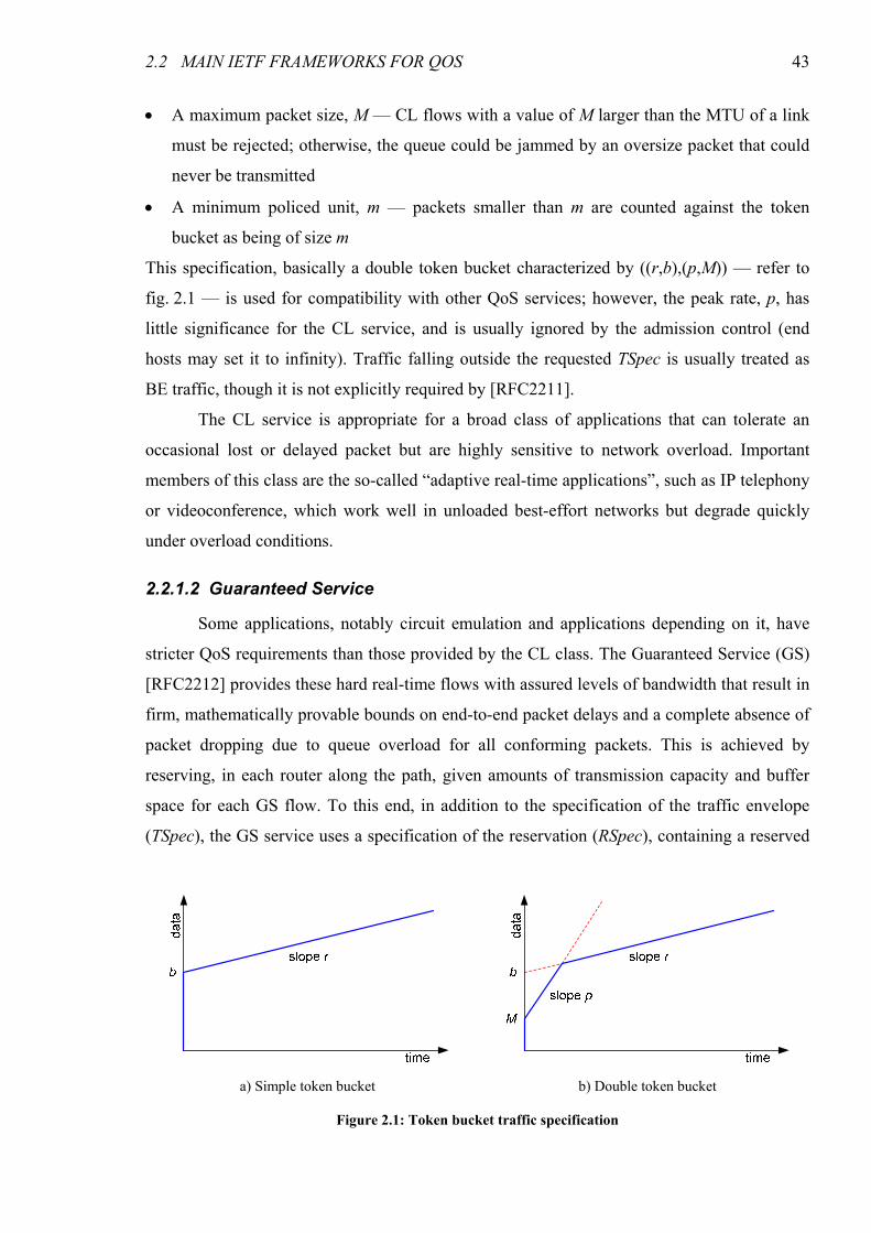
2.2 MAIN IETF FRAMEWORKS FOR QOS 43
• A maximum packet size, M — CL flows with a value of M larger than the MTU of a link
must be rejected; otherwise, the queue could be jammed by an oversize packet that could
never be transmitted
• A minimum policed unit, m — packets smaller than m are counted against the token
bucket as being of size m
This specification, basically a double token bucket characterized by ((r,b),(p,M)) — refer to
fig. 2.1 — is used for compatibility with other QoS services; however, the peak rate, p, has
little significance for the CL service, and is usually ignored by the admission control (end
hosts may set it to infinity). Traffic falling outside the requested TSpec is usually treated as
BE traffic, though it is not explicitly required by [RFC2211].
The CL service is appropriate for a broad class of applications that can tolerate an
occasional lost or delayed packet but are highly sensitive to network overload. Important
members of this class are the so-called “adaptive real-time applications”, such as IP telephony
or videoconference, which work well in unloaded best-effort networks but degrade quickly
under overload conditions.
2.2.1.2 Guaranteed Service
Some applications, notably circuit emulation and applications depending on it, have
stricter QoS requirements than those provided by the CL class. The Guaranteed Service (GS)
[RFC2212] provides these hard real-time flows with assured levels of bandwidth that result in
firm, mathematically provable bounds on end-to-end packet delays and a complete absence of
packet dropping due to queue overload for all conforming packets. This is achieved by
reserving, in each router along the path, given amounts of transmission capacity and buffer
space for each GS flow. To this end, in addition to the specification of the traffic envelope
(TSpec), the GS service uses a specification of the reservation (RSpec), containing a reserved
a) Simple token bucket b) Double token bucket
Figure 2.1: Token bucket traffic specification

44 CHAPTER 2 RELATED WORK
rate R and a slack parameter S (the amount of buffer space is not included in RSpec because it
may be derived by the router from the TSpec, RSpec and other received parameters).
In a fluid flow model, a flow bounded by a token bucket of rate r and depth b, for
which there is a reserved capacity R, is delayed by no more than b/R, provided that R ≥ r.
However, the GS is only an approximation of the fluid model (there is not a leased line, only
an amount of reserved capacity on a line where this flow is multiplexed with others);
therefore, two error terms are introduced to characterize the maximum deviation from the
ideal model: C (dependent on R) and D (independent of R). Using these error terms, the delay
bound becomes b/R + C/R + D. Since traffic envelope of GS flows is bounded by a double
token bucket (the TSpec) that limits the peak rate to p, a tighter bound on the end-to-end
queuing delay may be derived [Parekh93, Parekh94]; this bound is shown in eq. (2.1), where
Ctot and Dtot represent the summed values of the C and D parameters for all routers along the
path.
≥≥⇐++
≥>⇐++
+−
−−
≤
rpRDR
CM
rRpDR
CM
rpR
RpMb
QDelay
tottot
tottot
)(
))((
(2.1)
Note the absence of the first term of the delay in the second case, where the peak rate is lower
than the reserved rate — since the reserved capacity exceeds the peak rate, there is no need to
drain out the bucket.
The slack term S is used to add some flexibility to the reservation process, increasing
the chances of a reservation being accepted. The receiver requests a larger amount of
bandwidth than strictly required to meet the required delay bound, thus obtaining a lower
value for the bound, and places the difference in S. Routers using deadline-based schedulers
(which decouple rate and delay guarantees) that would not be able to meet the required delay
bound but could accept a larger bound, may still accept the reservation provided the slack is at
least as large as the difference between the bounds (the difference is subtracted from the value
of S sent upstream). On rate-based schedulers, a lower rate (than both the requested rate and
the minimum rate required to meet the end-to-end delay bound) may be reserved at a router
with insufficient capacity (and upstream) by consuming some slack, provided that eq. (2.2)
holds. In eq. (2.2), Ctoti is the sum of the C terms upstream of the current node, i, including
itself, (Rin, Sin) is the received RSpec and (Rout, Sout) the modified RSpec sent upstream.
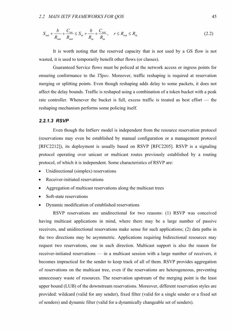
2.2 MAIN IETF FRAMEWORKS FOR QOS 45
inoutin
tot
inin
out
tot
outout , RRr
R
C
R
bS
R
C
R
bS i ≤≤++≤++ (2.2)
It is worth noting that the reserved capacity that is not used by a GS flow is not
wasted, it is used to temporarily benefit other flows (or classes).
Guaranteed Service flows must be policed at the network access or ingress points for
ensuring conformance to the TSpec. Moreover, traffic reshaping is required at reservation
merging or splitting points. Even though reshaping adds delay to some packets, it does not
affect the delay bounds. Traffic is reshaped using a combination of a token bucket with a peak
rate controller. Whenever the bucket is full, excess traffic is treated as best effort — the
reshaping mechanism performs some policing itself.
2.2.1.3 RSVP
Even though the IntServ model is independent from the resource reservation protocol
(reservations may even be established by manual configuration or a management protocol
[RFC2212]), its deployment is usually based on RSVP [RFC2205]. RSVP is a signaling
protocol operating over unicast or multicast routes previously established by a routing
protocol, of which it is independent. Some characteristics of RSVP are:
• Unidirectional (simplex) reservations
• Receiver-initiated reservations
• Aggregation of multicast reservations along the multicast trees
• Soft-state reservations
• Dynamic modification of established reservations
RSVP reservations are unidirectional for two reasons: (1) RSVP was conceived
having multicast applications in mind, where there may be a large number of passive
receivers, and unidirectional reservations make sense for such applications; (2) data paths in
the two directions may be asymmetric. Applications requiring bidirectional resources may
request two reservations, one in each direction. Multicast support is also the reason for
receiver-initiated reservations — in a multicast session with a large number of receivers, it
becomes impractical for the sender to keep track of all of them. RSVP provides aggregation
of reservations on the multicast tree, even if the reservations are heterogeneous, preventing
unnecessary waste of resources. The reservation upstream of the merging point is the least
upper bound (LUB) of the downstream reservations. Moreover, different reservation styles are
provided: wildcard (valid for any sender), fixed filter (valid for a single sender or a fixed set
of senders) and dynamic filter (valid for a dynamically changeable set of senders).
46 CHAPTER 2 RELATED WORK
In order to keep the robustness typical of datagram networks, where flows are rerouted
in order to restore the service whenever a node or link fails, RSVP uses soft state reservations,
which are torn down if not refreshed periodically. This means that should the path of a flow
with an established reservation change, the stale reservation on the old path will be removed,
freeing up resources for other flows. This, however, comes at the cost of increased overhead,
introduced by the refresh messages.
RSVP allows for dynamic changes in the reservations. However, the changes must be
subject to admission control, which may fail if the amount of reserved resources is being
increased.
2.2.1.3.1 Operation
An IntServ reservation is established using RSVP as follows [RFC2210] (refer also to
fig. 2.2). The sender begins by sending the Path message, used to install path state (as the
name implies); this message follows the same path as the data packets, and contains the
following information:
• Identification of the session, consisting on the destination IP address (which may be
multicast), the layer 4 protocol and, optionally, the destination port
• Identification of the previous hop (initialized with the sender’s IP address and updated at
every router along the path)
• The traffic envelope (TSpec) of the flow
• Optionally, an ADSPEC object; it is used to gather information on some path
characteristics (hop count, bottleneck bandwidth, minimum latency, MTU) and, in GS
reservations, the error terms (C and D)
After receiving the Path message, the receiver determines the amount of resources to be
reserved and sends a Resv message upstream to the sender. Thanks to the Path state stored at
the routers, the Resv message can follow exactly the reverse path of the Path message even if
the routes are asymmetric. On receiving the Resv message, each router submits the request to
Figure 2.2: RSVP messages
2.2 MAIN IETF FRAMEWORKS FOR QOS 47
admission control; if accepted, the message is forwarded upstream; otherwise, a ResvErr
message is sent to the receiver reporting the fact.
Since RSVP is a soft state protocol, Path and Resv messages must be periodically
refreshed, otherwise the reservation would timeout and be removed. Nevertheless, RSVP
provides PathTear and ResvTear messages for a faster removal of path and reservation state,
respectively, thus avoiding the waste of resources until the timeout.
2.2.1.4 Issues with IntServ
Even though the IntServ architecture, supported by the RSVP protocol, is able to
deliver the QoS guarantees necessary for soft and hard real-time applications on top of the
datagram-based Internet, it has not gained widespread acceptance as once expected. The most
frequently pointed out limitations of RSVP/IntServ concern its scalability to high-speed
backbone networks.
The first issue is the necessity for maintenance of per-flow state at every intermediate
node in the network, including core routers supporting a very large number of simultaneous
flows. While this is not as big a problem as it may seem at first (refer to chapter 4), it is still a
limitation, particularly given the complexity of RSVP processing. This complexity stems in
large part from the multicast-oriented design of the protocol; however, multicast has not
gained the importance once expected, and it is questionable if there is enough interest in
multicast to justify the extra complexity.
Another, more severe, issue with RSVP/IntServ is the necessity for computationally
complex packet scheduling algorithms and for packet classification based on the 5-tuples
identifying the flows. These operations must be performed for every packet, but their
complexity implies they cannot be performed at line rate in high speed backbone routers.
As a result of these scalability issues, RSVP/IntServ has been deployed only in small
scale in internal networks, where they are mitigated by the much smaller number of
simultaneous flows.
2.2.2 DiffServ
The scalability issues that plagued IntServ led the IETF to the development of a
radically different approach to QoS — the Differentiated Services (DiffServ) architecture
[RFC2475]. Contrary to IntServ, a fine-grained, flow-based mechanism, DiffServ is a coarse-
grained, class-based mechanism for traffic management. DiffServ scales very well since core
nodes do not perform most of the functions described in section 2.1 — they only perform
packet scheduling according to a small number of traffic classes, selected according to a
48 CHAPTER 2 RELATED WORK
single field of the IP packet header. The concept of service differentiation according to a field
in the packet header was not new: back in 1981, [RFC791] specified a Type of Service (ToS)
byte, containing a field specifying a precedence level and another one specifying the
requested type of service (the latter was primarily intended to be used for routing, though it
could also affect other aspects of datagram handling)1. The ToS model, however, was never
used in large scale.
A central concept in DiffServ is that of Per-Hop Behavior (PHB). A PHB is the
externally observable forwarding behavior applied at each node to a traffic aggregate.
Frequently, the description of a PHB is made with reference to other traffic, for example by
guaranteeing a PHB a certain fraction of the link capacity. Resource management is
performed according to the PHBs. When there are interdependencies in the specification of a
set of PHBs, the set is defined as PHB group with a unified specification2. The
implementation of PHBs is essentially based on queue management and packet scheduling
mechanisms. However, the specification of a PHB is based on the behavioral characteristics
relevant for the service, and frequently a given PHB may be implemented with different
mechanisms. Two PHB groups have been standardized by the IETF: the Assured Forwarding
(AF), providing high probability of forwarding to conformant packets, and the Expedited
Forwarding (EF), used to build a low loss, low latency, low jitter, assured capacity, end-to-
end transport service through DiffServ domains (“Virtual Leased Line” or “Premium”
service). These PHB groups will be described in sections 2.2.2.1 and 2.2.2.2.
In DiffServ, aggregates are identified by a 6 bit field in the packet header, the
Differentiated Services Code Point (DSCP). The DSCP corresponds to the leftmost 6 bits of
the DS field (a redefinition of the ToS octet in IPv4 or the Traffic Class octet in IPv6). The
collection of packets sharing the same DSCP and crossing a given link in a particular
direction is designated Behavior Aggregate (BA).
Two other very important concepts in the DiffServ architecture are those of Service-
Level Agreement (SLA) and Traffic Conditioning Agreement (TCA). An SLA is a contract
between a network operator and a customer (or between peering operators) containing a
specification of the network service to be provided — the Service Level Specification (SLS)
— including traffic treatment and performance metrics. The SLA may also contain a set of
traffic conditioning rules, designated TCA. The TCA specifies rules for packet classification,
1 For a complete history of the ToS byte, please refer to sec. 22 of [RFC3168]. 2 A single stand-alone PHB is considered a special case of a PHB group.
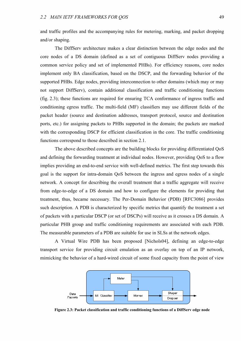
2.2 MAIN IETF FRAMEWORKS FOR QOS 49
and traffic profiles and the accompanying rules for metering, marking, and packet dropping
and/or shaping.
The DiffServ architecture makes a clear distinction between the edge nodes and the
core nodes of a DS domain (defined as a set of contiguous DiffServ nodes providing a
common service policy and set of implemented PHBs). For efficiency reasons, core nodes
implement only BA classification, based on the DSCP, and the forwarding behavior of the
supported PHBs. Edge nodes, providing interconnection to other domains (which may or may
not support DiffServ), contain additional classification and traffic conditioning functions
(fig. 2.3); these functions are required for ensuring TCA conformance of ingress traffic and
conditioning egress traffic. The multi-field (MF) classifiers may use different fields of the
packet header (source and destination addresses, transport protocol, source and destination
ports, etc.) for assigning packets to PHBs supported in the domain; the packets are marked
with the corresponding DSCP for efficient classification in the core. The traffic conditioning
functions correspond to those described in section 2.1.
The above described concepts are the building blocks for providing differentiated QoS
and defining the forwarding treatment at individual nodes. However, providing QoS to a flow
implies providing an end-to-end service with well-defined metrics. The first step towards this
goal is the support for intra-domain QoS between the ingress and egress nodes of a single
network. A concept for describing the overall treatment that a traffic aggregate will receive
from edge-to-edge of a DS domain and how to configure the elements for providing that
treatment, thus, became necessary. The Per-Domain Behavior (PDB) [RFC3086] provides
such description. A PDB is characterized by specific metrics that quantify the treatment a set
of packets with a particular DSCP (or set of DSCPs) will receive as it crosses a DS domain. A
particular PHB group and traffic conditioning requirements are associated with each PDB.
The measurable parameters of a PDB are suitable for use in SLSs at the network edges.
A Virtual Wire PDB has been proposed [Nichols04], defining an edge-to-edge
transport service for providing circuit emulation as an overlay on top of an IP network,
mimicking the behavior of a hard-wired circuit of some fixed capacity from the point of view
Figure 2.3: Packet classification and traffic conditioning functions of a DiffServ edge node
50 CHAPTER 2 RELATED WORK
of the originating and terminating nodes. An alternative Virtual Wire PDB has been proposed
in [Walter03] where the minimum jitter requirements are relaxed in order to obtain lower
delay values. The only PDB that has been published in the RFC series, however, is the Lower
Effort (LE) PDB [RFC3662], providing a background transport service for bulk applications
that can be starved by Best Effort traffic.
2.2.2.1 Assured Forwarding
The AF PHB group3 provides delivery of IP packets in four independently forwarded
AF classes. Each AF class is assigned a minimum amount of capacity and buffer space at
every node. Within each AF class, a packet can be assigned one of three different levels of
drop precedence. In case of congestion, the drop precedence of a packet determines the
relative importance of the packet within the AF class. A congested DS node tries to protect
packets with a lower drop precedence value from being lost by preferably discarding packets
with a higher drop precedence value. An important property of AF is that a DiffServ node
does not reorder packets of the same microflow if they belong to the same AF class, even
though they may have different drop precedence levels.
In nodes supporting AF, short periods of congestion should be absorbed by buffering.
Congestion in larger temporal scales needs to be controlled through packet dropping.
However, packet dropping should be gradual rather than abrupt, requiring the use of Active
Queue Management (AQM) techniques. Within an AF class, a DS node must not forward a
packet with smaller probability if it contains a drop precedence value p than if it contains a
drop precedence value q when p < q. Multi-level extensions of the Random Early Detection
(RED) [Floyd93] mechanism with cumulative queue lengths such as RED with In and Out bit
(RIO) [Clark98] or Generalized RED (GRED) [Almesberger99] are suitable for the
implementation of the drop precedence levels within each AF class.
2.2.2.2 Expedited Forwarding
The Expedited Forwarding PHB, first defined in [RFC2598], provides very low loss,
queuing delay and jitter to conformant IP packets; this is achieved by always guaranteeing a
minimum capacity for EF traffic that the arrival rate must not exceed, independently of traffic
of other PHBs. The EF PHB is, therefore, appropriate for circuit emulation services.
3 Strictly speaking, AF is a type of PHB group, since the operation of each AF class is entirely independent of the others;
each AF class is an instance of the AF PHB group type [RFC3260].
2.3 OTHER QOS MODELS 51
The original definition lacked mathematical precision and introduced unnecessary
limitations on the schedulers, and was obsoleted by a new, more formal definition in
[RFC3246]. This new definition introduces packet-scale rate guarantees, in addition to the
aggregate guarantees previously specified; it also clarifies the behavior of EF routers with
multiple inputs and/or complex scheduling. Similarly to AF, EF packets belonging to the
same microflow cannot be reordered.
The implementation of the EF PHB requires a scheduling mechanism that can
guarantee a minimum rate at the packet scale. A simple implementation may be based on a
strict priority scheduler, with EF traffic having the highest priority. Ensuring that the arrival
rate does not exceed the minimum capacity requires traffic conditioning (policing/shaping)
mechanisms to be performed at the network boundaries; this also ensures that other classes do
not starve due to excess EF traffic.
2.2.2.3 Issues with DiffServ
Based on simple and efficient mechanisms, DiffServ provides a very scalable
foundation for deploying QoS on high-speed IP networks. At the core nodes, only a minimal
amount of state is maintained, corresponding to a small number of traffic classes, and packet
classification and scheduling are efficient. However, DiffServ cannot provide QoS to end-user
flows by itself — there is no per-flow reservation of resources or admission control. More
than a limitation, it is a characteristic of DiffServ — it is a tool for network operators, not
end-users, and provides QoS for aggregates, not individual flows. End-to-end QoS-enabled
packet delivery services may be built on top of the DiffServ foundation using additional
layers that provide the missing features; notable examples are the Bandwidth-Broker-based
architectures described in section 2.3.4.
2.3 Other QoS Models
In spite of its scalability problems, IntServ provides hard per-flow QoS guarantees,
which cannot be achieved with DiffServ. A lot of research has undergone towards the goal of
providing the per-flow guarantees of the IntServ model (or, at least, some of those guarantees)
with improved scalability. This section describes some of the resulting proposals.
2.3.1 Alternative Signaling
Since some of the issues of RSVP/IntServ concern the signaling protocol itself,
several proposals have been made for QoS signaling protocols with more desirable properties.
52 CHAPTER 2 RELATED WORK
2.3.1.1 Simplified Signaling
Based on the premise that a significant portion of the applications requiring QoS were
multimedia oriented, the Yet Another Sender Session Internet Reservation (YESSIR) protocol
was proposed [Pan99] as an extension of the Real-Time Control Protocol (RTCP), the
companion to Real-Time Protocol (RTP) used by many such applications. YESSIR is a
sender-initiated, soft-state protocol, and provides support for partial reservations that may be
improved over time, as resources become available. YESSIR has faster processing and
smaller overhead than RSVP, and yet retains most of its functions, notably multicast (though
supporting only individual and shared reservation styles). With YESSIR, per-flow state is still
maintained at the routers, and since it concerns only signaling, no improvement is made with
respect to RSVP regarding packet classification and scheduling; therefore, it suffers from
similar scalability limitations in these respects.
Another proposal for simplified QoS signaling is Boomerang [Fehér99], a duplex,
soft-state reservation protocol. Boomerang was implemented as an extension of ICMP Echo
function, and requires no special functionality on the far-end node. It is possible to use per-
flow reservations, but measurement-based admission control may also be used; in the last
case, there is no need to maintain per-flow state at the routers, but only soft QoS may be
provided (a similar limitation exists in probing-based admission control, described below).
Test results indicate that Boomerang is much lighter-weight than RSVP, both in terms of CPU
power and memory space [Fehér99, Fehér02]; however, it has reduced functionality, and
when used with per-flow QoS, packet classification and scheduling procedures are still
scalability-limiting.
2.3.1.2 Next Steps in Signaling (NSIS)
The Next Steps in Signaling (NSIS) Working Group has proposed a two-layer
extensible signaling architecture [RFC4080] that addresses many limitations of RSVP, having
QoS signaling as one of the first applications4 [Fu05]. One interesting feature of NSIS is the
separation between signaling message transport and signaling applications, provided by two
different layers. The lower layer, designated NSIS Transport Layer Protocol (NTLP),
provides a generic transport service for different signaling applications that reside in the upper
layer, the NSIS Signaling Layer Protocols (NSLPs). This layered approach simplifies the
design of new signaling applications.
4 Other applications are Network Address Translation (NAT) hole punching / Firewall control and metering.
2.3 OTHER QOS MODELS 53
The main part of the NTLP is the General Internet Signaling Transport (GIST)
protocol [Schulzrinne06]. It runs on top of standard transport protocols — User Datagram
Protocol (UDP), Transmission Control Protocol (TCP), Stream Control Transmission
Protocol (SCTP) and Datagram Congestion Control Protocol (DCCP) — and reuses existing
Transport Layer Security (TLS) and IP layer security (IPSec/IKEv2). The use of a
cryptographically random session identifier for signaling sessions, independent of the flow
identifier, is useful in mobility scenarios, where the flow identifier may change. In addition to
signaling transport, GIST provides peer discovery and capability querying services, and
supports advanced features such as the negotiation of transport and security protocols,
recovery from route changes and interaction with NAT and IP Tunneling.
The proposed NSLP for QoS [Manner06], together with GIST, provides functionality
extending that of RSVP: it is also a soft-state protocol, and supports sender-initiated, receiver-
initiated and bidirectional reservations, as well as reservations between arbitrary nodes (end-
to-end, edge-to-edge, end-to-edge, etc.). The QoS NSLP is independent of the underlying
QoS architecture, and provides support for different reservation models, including models
based on flow aggregation (described in section 2.3.2). A separate document [Bader06]
specifies the use of NSIS to implement the Resource Management in DiffServ (RMD) model,
described below (section 2.3.2.3). Unlike RSVP, there is no support for multicast, thus
reducing the complexity for the majority of the applications, which are unicast.
NSIS concerns signaling only, and was designed to support any QoS model. As a
result, its characteristics in terms of QoS, resource utilization and scalability are largely
dependent on the underlying QoS model.
2.3.2 Aggregation-based schemes
The aggregation of individual flows, the basic idea behind DiffServ, allows not only
for a substantial reduction in the amount of state that routers are required to maintain, but
also, more importantly, for more computationally efficient packet classification and
scheduling mechanisms. Under certain circumstances, aggregation may also allow for a large
decrease in signaling overhead. This section describes some QoS models using flow
aggregation to attain better scalability.
2.3.2.1 IntServ over DiffServ
With the goal of simultaneously reaping the benefits of RSVP/IntServ (per-flow QoS)
and DiffServ (scalability in the core), a framework was proposed for supporting IntServ over
DiffServ networks [RFC2998]. End-to-end, quantitative QoS is provided by applying the
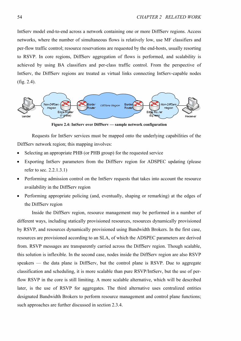
54 CHAPTER 2 RELATED WORK
IntServ model end-to-end across a network containing one or more DiffServ regions. Access
networks, where the number of simultaneous flows is relatively low, use MF classifiers and
per-flow traffic control; resource reservations are requested by the end-hosts, usually resorting
to RSVP. In core regions, DiffServ aggregation of flows is performed, and scalability is
achieved by using BA classifiers and per-class traffic control. From the perspective of
IntServ, the DiffServ regions are treated as virtual links connecting IntServ-capable nodes
(fig. 2.4).
Requests for IntServ services must be mapped onto the underlying capabilities of the
DiffServ network region; this mapping involves:
• Selecting an appropriate PHB (or PHB group) for the requested service
• Exporting IntServ parameters from the DiffServ region for ADSPEC updating (please
refer to sec. 2.2.1.3.1)
• Performing admission control on the IntServ requests that takes into account the resource
availability in the DiffServ region
• Performing appropriate policing (and, eventually, shaping or remarking) at the edges of
the DiffServ region
Inside the DiffServ region, resource management may be performed in a number of
different ways, including statically provisioned resources, resources dynamically provisioned
by RSVP, and resources dynamically provisioned using Bandwidth Brokers. In the first case,
resources are provisioned according to an SLA, of which the ADSPEC parameters are derived
from. RSVP messages are transparently carried across the DiffServ region. Though scalable,
this solution is inflexible. In the second case, nodes inside the DiffServ region are also RSVP
speakers — the data plane is DiffServ, but the control plane is RSVP. Due to aggregate
classification and scheduling, it is more scalable than pure RSVP/IntServ, but the use of per-
flow RSVP in the core is still limiting. A more scalable alternative, which will be described
later, is the use of RSVP for aggregates. The third alternative uses centralized entities
designated Bandwidth Brokers to perform resource management and control plane functions;
such approaches are further discussed in section 2.3.4.
Figure 2.4: IntServ over DiffServ — sample network configuration
2.3 OTHER QOS MODELS 55
The IntServ over DiffServ framework requires the DiffServ regions of the network to
provide support for the standard IntServ services between the border routers. While such
support is relatively easy to implement for the Controlled Load service, particularly in
DiffServ networks with Bandwidth-Broker-based control of resources, it is hard to provide
the strict delay bounds of the Guaranteed Service in aggregation-based networks. Such
bounds can be achieved by priority schedulers, but only at the cost of very low link utilization
for the traffic class supporting the GS traffic [Charny00].
The IntServ over DiffServ framework does not provide a complete solution that can be
readily deployed — [RFC2998] clearly states that more work is required in several areas
(service mapping, functionality for using RSVP signaling with aggregate traffic control,
resource management mechanisms) before coming up with such solution.
2.3.2.2 RSVP Reservation Aggregation
The RSVP Reservation Aggregation model, standardized in [RFC3175], defines an
extension to RSVP by which individual end-to-end flows may be aggregated into a single
reservation inside a DiffServ region, where they share common ingress and egress nodes. The
establishment of a smaller number of aggregate reservations on behalf of a larger number of
end-to-end reservations yields the corresponding reduction in the amount of state maintained
at the routers. Hierarchical aggregation may be achieved by applying the method recursively.
Aggregate reservations are dynamically established between the ingress nodes
(aggregators) and the egress nodes (deaggregators), and are updated in bulk quantities much
larger than the individual rates of the flows in order to reduce the signaling overhead.
Whenever a flow requests admission in an aggregate region, the edge routers of the region
check if there is enough bandwidth to accept the flow on the aggregate. If resources are
available, the flow will be accepted without any need for signaling the core routers.
Otherwise, the core routers will be signaled in an attempt to increase the aggregate’s
bandwidth. If this attempt succeeds, the flow is admitted; otherwise, it is rejected.
By using DiffServ mechanisms for packet classification and scheduling (rather than
performing them per aggregate reservation), the amount of classification and scheduling state
and the complexity of these procedures in the aggregation region is even further reduced — it
is independent not only of the number of end-to-end reservations, but also of the number of
aggregate reservations in the aggregation region.
The main disadvantage of this model is the underutilization of network resources.
Since the bandwidth of each aggregate is updated in bulk quantities, each aggregate’s
bandwidth is almost never fully utilized. The unused bandwidth of all aggregates traversing a
56 CHAPTER 2 RELATED WORK
link adds up, leading to a significant amount of wasted link capacity. The RSVP Reservation
Aggregation model is described and analyzed in more detail in the next chapter.
2.3.2.3 Resource Management in DiffServ (RMD)
Based on similar principles to RSVPRAgg, the Resource Management in DiffServ
(RMD) [Westberg02] was introduced as a method for dynamic reservation of resources within
a DiffServ domain. It provides admission control for flows entering the domain and a
congestion handling algorithm that is able to terminate flows in case of congestion due to a
sudden failure (e.g., link, router) within the domain.
The RMD framework defines two types of protocols: the Per-Domain Reservation
(PDR) protocol and the Per-Hop Reservation (PHR) protocol. The PDR is triggered at the
edge nodes, and is used for resource management in the entire domain. Though the PDR
could be an existing protocol, such as RSVP, a newly defined one was used in [Westberg02].
The PHR is a complement to the DiffServ PHB, providing reservation of resources per traffic
class at every node within the domain. PDR messages are usually carried encapsulated in
PHR messages. A PHR protocol named RMD On-Demand (RODA) protocol was defined; it
is reservation-based, unicast, edge-to-edge protocol designed for a single DiffServ domain,
aiming at simplicity, low implementation cost and scalability.
Similarly to RSVP Reservation Aggregation, scalability in RMD is achieved by
separating a fine-grained reservation mechanism used in the edge nodes of the DiffServ
domain from a much simpler reservation mechanism used in the interior nodes. The limited
functionality supported by the interior nodes allows for fast processing of signaling messages.
As previously stated, the RMD model is also supported by the NSIS signaling stack.
2.3.3 Elimination of State in the Core
Since the necessity for maintaining state in core routers is usually regarded as one of
the major factors limiting the scalability of the RSVP/IntServ model, a significant amount of
work has undergone in the development of models based on stateless core routers. This
section describes the most prominent models in this class.
2.3.3.1 Probing-Based Admission Control
In accordance with the “end-to-end principle” [Saltzer84], one of the architectural
guidelines of the Internet [RFC3439], several schemes have been proposed where the
complexity is moved to the endpoints and (some degree of) QoS is provided with minimal or
no intervention of the network routers [Bianchi00, Breslau00b, Elek00, Gibbens99, Kelly00,
2.3 OTHER QOS MODELS 57
Sargento01, Key03]. The probing approach may be regarded as an extreme case of
aggregation: all flows are aggregated into a single queue per output port of the routers5, and
QoS provisioning is based on admission control performed by the terminals themselves. The
admission control decision is based on the network congestion level as measured by the
endpoints.
The probing technique is split into two phases: the probing phase and the data phase.
In the probing phase, a packet sequence is sent with similar characteristics to the flow being
admitted for a certain time. At the end of this phase, the receiver sends information on the
QoS of the received stream to the sender; based on this information, the sender decides if the
flow is admitted or rejected. If the flow is admitted, the actual flow data may be transmitted;
this is called the data phase. Some QoS parameters commonly used for the admission control
are packet delay or delay variation and packet loss or marking ratio.
There are some differences among the proposed probing mechanisms. In [Elek00] and
[Bianchi00], probe packets are sent with lower priority than data packets. If the loss ratio after
the probing period is acceptable, the flow is admitted — odds are that the loss ratio for the
data packets will be less than that of the probes, which have lower priority. In [Gibbens99],
[Kelly01] and [Key03], probe and data packets are treated equally, and admission is decided
based on the ratio of packets marked with Explicit Congestion Notification (ECN)
[RFC3168], instead of the packet loss. It is expected that routers start marking packets long
before the congestion level leads to packet loss. Since the number of marked packets is much
larger than the number of dropped packets the duration of the probing phase may be
significantly reduced [Kelly01]. In order to avoid a problem known as thrashing (a large
number of flows simultaneously try admission and fail, even though the network has enough
resources to admit some of them), [Breslau00] proposes two techniques. The Slow Start
Probing technique consists on splitting the probing phase into intervals and sending probe
packets at increasing rates; in the last interval, probes are sent at the same rate of the flow. If,
at the end of an interval, the loss rate exceeds a given threshold, the flow is rejected and
probes stop being sent. The Early Reject technique is similar, but probes are sent at the final
rate in all intervals. Another identified problem was resource stealing: since there is no
resource reservation, a new flow may reduce the QoS received by previously admitted flows.
The ε-probing technique [Sargento01] mitigates this problem in multi-class networks: in
5 While, strictly speaking, this is not necessarily true (there is no incompatibility between probing and differentiation), the use
of different queues for service differentiation is orthogonal to the probing concept.
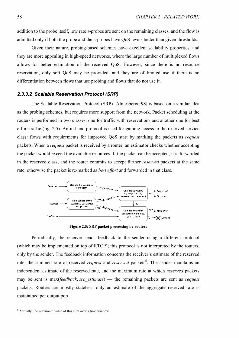
58 CHAPTER 2 RELATED WORK
addition to the probe itself, low rate ε-probes are sent on the remaining classes, and the flow is
admitted only if both the probe and the ε-probes have QoS levels better than given thresholds.
Given their nature, probing-based schemes have excellent scalability properties, and
they are more appealing in high-speed networks, where the large number of multiplexed flows
allows for better estimation of the received QoS. However, since there is no resource
reservation, only soft QoS may be provided, and they are of limited use if there is no
differentiation between flows that use probing and flows that do not use it.
2.3.3.2 Scalable Reservation Protocol (SRP)
The Scalable Reservation Protocol (SRP) [Almesberger98] is based on a similar idea
as the probing schemes, but requires more support from the network. Packet scheduling at the
routers is performed in two classes, one for traffic with reservations and another one for best
effort traffic (fig. 2.5). An in-band protocol is used for gaining access to the reserved service
class: flows with requirements for improved QoS start by marking the packets as request
packets. When a request packet is received by a router, an estimator checks whether accepting
the packet would exceed the available resources. If the packet can be accepted, it is forwarded
in the reserved class, and the router commits to accept further reserved packets at the same
rate; otherwise the packet is re-marked as best effort and forwarded in that class.
Periodically, the receiver sends feedback to the sender using a different protocol
(which may be implemented on top of RTCP); this protocol is not interpreted by the routers,
only by the sender. The feedback information concerns the receiver’s estimate of the reserved
rate, the summed rate of received request and reserved packets6. The sender maintains an
independent estimate of the reserved rate, and the maximum rate at which reserved packets
may be sent is max(feedback, src_estimate) — the remaining packets are sent as request
packets. Routers are mostly stateless: only an estimate of the aggregate reserved rate is
maintained per output port.
6 Actually, the maximum value of this sum over a time window.
Figure 2.5: SRP packet processing by routers
2.3 OTHER QOS MODELS 59
With minimal support from the routers, the SRP model provides a differentiated
reserved class, which supports dynamically changeable and partial reservations, and dispenses
with a probing phase. However, similarly to probing schemes, it provides only soft QoS.
2.3.3.3 Egress Admission Control
The Egress Admission Control proposal [Cetinkaya01] holds some similarities to the
RSVP Reservation Aggregation proposal: end-to-end reservation requests are hidden inside
the network, and the flow admission decision is taken by the egress router (deaggregator in
RSVPRAgg). However, in this case no state is maintained in the interior nodes: there are no
reservations for edge-to-edge aggregates, and flow admission decisions are taken based on a
“black box” model of the network, characterized by measured arrival and service envelopes of
the aggregate traffic flowing between the ingress and the egress routers. The arrival and
service envelopes are measurement-based statistical counterparts of the deterministic arrival
curve and service curve concepts. They account for interfering cross traffic without explicitly
measuring or controlling it.
Even though only statistical guarantees (soft QoS) can be provided, this framework
supports different traffic classes with varying degrees of QoS guarantees. Such differentiation
is obtained not only through the envelopes of the different traffic classes, but also by the use
of a level of confidence in the flow admission process, expressing the confidence that the
system will actually deliver the announced QoS. As a result, Egress Admission Control is able
to provide better guarantees than the previously mentioned core-stateless schemes.
2.3.3.4 SCORE
At the high-end of the core-stateless architectures in terms of QoS guarantees is the
Stateless Core (SCORE) [Stoica99, Stoica00]. Based on the concept of Dynamic Packet State
(DPS), where each packet carries state information initialized by the ingress router and
updated at every hop, the SCORE architecture is able to provide IntServ end-to-end per-flow
rate and delay guarantees without recourse to state maintenance at core nodes.
A SCORE network closely approximates the behavior of a per-flow stateful network,
specifically a network where every node implements the Jitter Virtual Clock (JVC)
scheduling algorithm. It has been shown that, as long as a flow’s arrival rate does not exceed
its reserved rate, such network is able to provide the same delay bounds as a network
implementing the Weighted Fair Queuing (WFQ) scheduling algorithm [Demers89],
commonly used in the deployment of the RSVP/IntServ model.
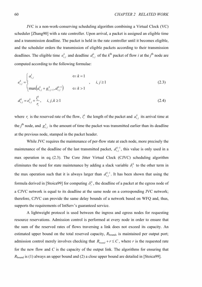
60 CHAPTER 2 RELATED WORK
JVC is a non-work-conserving scheduling algorithm combining a Virtual Clock (VC)
scheduler [Zhang90] with a rate controller. Upon arrival, a packet is assigned an eligible time
and a transmission deadline. The packet is held in the rate controller until it becomes eligible,
and the scheduler orders the transmission of eligible packets according to their transmission
deadlines. The eligible time k
jie , and deadline k
jid , of the kth packet of flow i at the jth node are
computed according to the following formulae:
( )1,,
1,max
1
1,1,,
1,
, ≥
>⇐+
=⇐
=−
−
ji
kdga
ka
ek
ji
k
ji
k
ji
ji
k
ji (2.3)
1,,,,, ≥+= kjir
led
i
k
ik
ji
k
ji (2.4)
where ir is the reserved rate of the flow, k
il the length of the packet and k
jia , its arrival time at
the jth node, and k
jig , is the amount of time the packet was transmitted earlier than its deadline
at the previous node, stamped in the packet header.
While JVC requires the maintenance of per-flow state at each node, more precisely the
maintenance of the deadline of the last transmitted packet, 1,−k
jid , this value is only used in a
max operation in eq. (2.3). The Core Jitter Virtual Clock (CJVC) scheduling algorithm
eliminates the need for state maintenance by adding a slack variable k
iδ to the other term in
the max operation such that it is always larger than 1,−k
jid . It has been shown that using the
formula derived in [Stoica99] for computing k
iδ , the deadline of a packet at the egress node of
a CJVC network is equal to its deadline at the same node on a corresponding JVC network;
therefore, CJVC can provide the same delay bounds of a network based on WFQ and, thus,
supports the requirements of IntServ’s guaranteed service.
A lightweight protocol is used between the ingress and egress nodes for requesting
resource reservations. Admission control is performed at every node in order to ensure that
the sum of the reserved rates of flows traversing a link does not exceed its capacity. An
estimated upper bound on the total reserved capacity, Rbound, is maintained per output port;
admission control merely involves checking that CrRbound ≤+ , where r is the requested rate
for the new flow and C is the capacity of the output link. The algorithms for ensuring that
Rbound is (1) always an upper bound and (2) a close upper bound are detailed in [Stoica99].
2.3 OTHER QOS MODELS 61
The SCORE architecture succeeds in eliminating the need for state maintenance in the
core. In doing so, the need for packet classification at core nodes is also eliminated, which is
important for scalability, as complex MF classification is computationally expensive.
However, the scheduling mechanism is still complex, as packets need to be sorted according
to their deadlines; moreover, packets in the rate controller need also be sorted according to
their eligible times.
2.3.4 Bandwidth Brokers
A number of proposals have been made where resource management, signaling and
admission control are performed by centralized entities, commonly designated Bandwidth
Brokers (BBs) [RFC2638, Terzis99, Duan04], but also known under different names (Agents
[Schelén98], Oracles [RFC2998], Clearing Houses [Chuah00], QoS Brokers [Marques03] or
Domain Resource Managers [Hillebrand04]). Models based on BBs decouple the QoS control
plane from the data plane. Since many control plane functions are performed per flow,
scalability can be greatly enhanced by offloading these responsibilities from the core nodes.
BB-based models are often used in conjunction with DiffServ, since the two
technologies are complementary: DiffServ provides a scalable model for data plane QoS
functions, such as edge traffic conditioning and packet classification and scheduling, and BBs
perform QoS signaling, flow admission control and resource management, control plane
functions that are missing in DiffServ.
One important advantage of centralizing QoS control in BBs is the possibility of using
sophisticated admission control and QoS provisioning algorithms that allow for a network-
wide optimization of the resources, something that is difficult to achieve with distributed
schemes. This optimization can easily incorporate policy aspects. Moreover, BBs can also
support additional functions, such as support for mobility or inter-domain resource
reservation; these functions and QoS control may be performed in an integrated fashion.
Another advantage of a centralized approach is that QoS state consistency issues are avoided
— in distributed approaches, these issues are partially solved by using soft states; however,
the need for periodical refreshment of soft states increases the signaling overhead.
Schelén and Pink [Schelén98] proposed a model where a BB gains knowledge of the
network topology by passively listening to a link state routing protocol (e.g., OSPF) and
retrieves detailed information, such as link bandwidth, using a network management protocol
(e.g., SNMP). Parameter-based admission control for priority traffic is performed based on
information maintained at the BB regarding reserved resources at each link. In addition to
intra-domain resource management, BBs in different domains use a protocol for establishing
62 CHAPTER 2 RELATED WORK
inter-domain aggregate reservations, designated funnels, towards a given subnetwork,
identified by its address prefix.
Originally published as an Internet Draft in 1997, [RFC2638] proposes an architecture
supporting two elevated services — a Premium service with firm QoS guarantees that may be
used to emulate virtual leased lines, and an Assured service providing the soft guarantee of a
very low probability of packet dropping. On the data plane, differentiation is based on a two-
bit field of the packet header, a mechanism that came to be the basis for the DiffServ model.
On the control plane, each domain has a BB which keeps track of reservations, that can be
static or dynamic, manages resources, and configures the traffic conditioning mechanisms at
the border routers (aggregate) and access routers (per flow). Additionally, BBs in different
domains exchange messages in order to establish end-to-end reservations that are aggregated
according to the destination.
A BB-based two-tier model for resource management was proposed in [Terzis99].
Different resource management models are used for access (leaf) and transit domains. Intra-
domain resource management is mostly done using RSVP, either per-flow (access domains)
or aggregate (transit domains), and BBs are mostly used to manage inter-domain reservations.
At access domains, the sender uses RSVP, but the Path message is intercepted by the first hop
router, which sends a reservation request to the BB7. If enough bandwidth is available at the
egress router towards the downstream domain, the BB tells the first hop router to forward the
Path message, and the egress router to start sending Resv messages towards the sender, thus
performing an RSVP/IntServ reservation between the sender and the egress router. Since
RSVP is terminated at the egress of the sender’s domain, receivers need an out-of-band
mechanism to know the traffic profile of the source (it is suggested that this is performed at
the application layer). The receiver sends a request to the BB, and the BB tells the ingress
router to perform an RSVP/IntServ reservation to the receiver.
In transit domains, QoS at the data plane is provided by DiffServ. Ingress routers
measure aggregate traffic towards each egress router (which they know since they are
assumed to participate in inter-domain routing using the Border Gateway Protocol
[RFC4271]). Using this information, they build a Tspec that is sent in an aggregate RSVP
Path message towards the egress node; this node responds with an aggregate Resv message.
The BBs of adjacent domains communicate among themselves to establish dynamic
traffic conditioning aggreements. Inter-domain reservations take into consideration only the
7 This implicitly limits the architecture to a controlled load service, since in guaranteed service the amount of resources to
reserve can only be known from the Resv message.
2.3 OTHER QOS MODELS 63
downstream domain, not the entire path. Edge routers measure the rate of the outgoing
aggregate using a time window algorithm (see appendix A), and use a watermark-based
algorithm to request an increase or decrease in the reservation. If more than a fraction w of the
reserved capacity is in use, the BB is informed to increase the reserved rate to the downstram
domain; in response, the BB of the downstream domain tells the ingress router to increase the
reservation by a value δ, which is proportionally distributed among the aggregates originated
at that node. If less than a fraction l (with l < w) is in use, the BB is informed to decrease the
reserved rate, using a hysteresis mechanism to avoid Ripple effect.
An advantage of this model is a simple, albeit imprecise, method for managing inter-
domain resources. Some disadvantages are a mixed approach to resource reservation at the
access domains that is cumbersome, and the support for controlled load services only.
A hierachical BB model is proposed in [Chuah00]. Basic routing domains managed by
a Local Clearing House (LCH) are aggregated into a hierarchy of logical domains, associated
with Global Clearing Houses (GCH) that manage inter-domain reservations. For performance
reasons, resources are reserved in advance using a Gaussian predictor based on measured
aggregate traffic (the possibility of on-demand reservations is mentioned, but not specified in
the proposal). Two other techniques are used to improve the responsiveness of the reservation
mechanism: RxW scheduling of reservation requests and caching of intra- and inter-domain
computed paths of previous reservations. An interesting feature of the architecture is the
possibility for secure real-time billing.
An entirely core-stateless approach supporting the IntServ per-flow Guaranteed
Service, as well as a class-based guaranteed delay service with flow aggregation, was
proposed in [Duan04]. The data plane is based on an improved version of the SCORE
architecture, which may use a combination of core-stateless rate-based schedulers — such as
the Core-Stateless Virtual Clock (CS’ VC) [Zhang00b], a work-conserving version of the CJVC
described in section 2.3.3.4 — and delay-based schedulers — such as the Virtual Time
Earliest Deadline First (VT-EDF) [Zhang00b]. On the control plane, a BB with detailed
knowledge of the network topology keeps track of the reservations and performs admission
control, ensuring that the worst case edge-to-edge delay requirements of the flows, defined by
a dual token bucket TSpec, can be met. Flow admission requests are issued by the edge
routers in response to external stimuli, such as the arrival of an RSVP reservation request. In
an attempt at reducing the admission control delay, the process is split into two phases:
admission test and bookkeeping; the latter can be performed after the reservation response.
Nevertheless, while this splitting ensures O(1) complexity for the admission test, it requires
64 CHAPTER 2 RELATED WORK
the bookkeeping phase to update not only the state of all routers along the edge-to-edge path,
but also for all paths traversing any of those routers. In practical terms, it means that
admission control is very responsive for a single request but slow when a number of requests
is performed in a short period.
The greatest concern with BBs is that by concentrating the intelligence for resource
management, they become single points of failure, and may easily become bottlenecks in the
control plane. However, these problems can be mitigated through the use of standard
techniques for server redundancy and load sharing. Moreover, they allow the optimization of
the control plane to be handled orthogonally to the optimization of the data plane.
One important aspect of BB-based architectures for QoS provisioning is the ease of
integration of mobility management in the resource management model. This aspect is of
major importance for providing QoS to mobile terminals with wireless access technologies,
since such integration is necessary for minimizing the network service disruption as the
terminals move across different cells. Additionally, other operational aspects of the network,
such as policy enforcement, accounting and billing may easily be incorporated into the BB,
making BB-based models very appealing for next generation IP-based mobile networks.
Section 2.5.2 presents a proposed BB-based architecture for next generation networks.
2.4 Inter-Domain QoS
The Internet is not a flat collection of interconnected routers; it is organized in a two-
level hierarchy. At the higher level, the Internet consists on a large number of interconnected
Autonomous Systems (ASs). An AS is a set of routers under a single technical administration,
having a single coherent interior routing plan and presenting a consistent picture of the
destinations that are reachable through it. ASs are connected via gateways (the border
routers), which run an inter-domain routing protocol to exchange routing information about
which hosts are reachable by each AS. As a result, each gateway constructs a routing table
that maps each IP address to a neighbor AS that knows a path to that IP address. The ASs can
be broadly classified into two types: stub ASs, which only carry traffic generated at or
destined to internal addresses (even though they may be multi-homed), and transit ASs, which
have multiple connections to other ASs and carry traffic originated at and destined to external
addresses. Transit ASs vary widely in dimension and geographical presence, and may be
accordingly classified in tiers. An interesting analysis of the structure of the Internet, based on
the inter-domain routing tables observed at several vantage points, is presented in
[Subramanian02].
2.4 INTER-DOMAIN QOS 65
There are two different aspects involved in providing inter-domain QoS: the first one
is finding a route capable of satisfying the QoS requirements of the application flows; the
second one is performing reservations for ensuring that enough resources are available for the
traffic demand. These aspects are complementary, but orthogonal: resource reservations may
be performed over a QoS-optimized path or over a non-QoS-optimized path provided by
BGP; conversely, inter-domain QoS routing is useful even without resource reservations. The
next sections discuss these two aspects.
2.4.1 Inter-Domain Resource Reservation
The greatest technical problem with inter-domain resource reservation is scalability:
the large number of ASs in the Internet8 makes even aggregate reservations per (source AS,
destination AS) challenging. The next paragraphs describe some of the more relevant work in
this field.
The Border Gateway Reservation Protocol (BGRP) [Pan00] operates end-to-end, but
only between border routers. It is a soft-state protocol based on the aggregation of
reservations along the sink trees created by BGP, rooted on the destination domain (fig. 2.6).
BGRP uses five control message types: Probe and Graft, used to establish a reservation,
Refresh to keep the reservations active and update them, Tear for quicker removal of
reservations, and Error to report errors during probing or grafting; these messages are sent
reliably. BGRP signaling holds some similarities to RSVP signaling — Probe and Graft
messages (fig. 2.6), for example, work quite similarly to RSVP’s Path and Resv messages
(fig. 2.2). There are, however, some important differences. (1) BGRP runs only between
border routers. (2) BGRP uses stateless probing: no state is stored in the routers on processing
Probe messages; instead, the router’s address is added to a route record in the message itself,
which is used to source route the corresponding Graft message along the reverse path. (3)
BGRP does not work with individual reservations, but with aggregates; moreover,
reservations from different upstream domains to the same sink are aggregated into a single
downstream reservation (sum of the upstream reservations), ensuring that the amount of
stored state is O(N), where N is the number of different domains (possible sinks). (4) Soft-
state refreshments are bundled, in order to reduce the signaling overhead. (5) BGRP
reservations are sender-initiated — Probe messages contain the reservation request, and
admission control is performed when they are processed.
8 As of December 2006, there are nearly 24000 different advertised ASs in the Internet [CIDRRep].
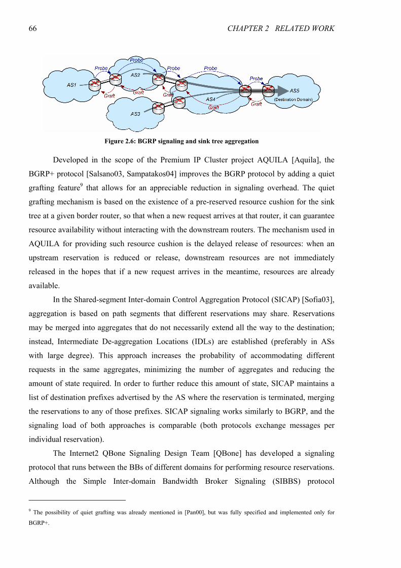
66 CHAPTER 2 RELATED WORK
Developed in the scope of the Premium IP Cluster project AQUILA [Aquila], the
BGRP+ protocol [Salsano03, Sampatakos04] improves the BGRP protocol by adding a quiet
grafting feature9 that allows for an appreciable reduction in signaling overhead. The quiet
grafting mechanism is based on the existence of a pre-reserved resource cushion for the sink
tree at a given border router, so that when a new request arrives at that router, it can guarantee
resource availability without interacting with the downstream routers. The mechanism used in
AQUILA for providing such resource cushion is the delayed release of resources: when an
upstream reservation is reduced or release, downstream resources are not immediately
released in the hopes that if a new request arrives in the meantime, resources are already
available.
In the Shared-segment Inter-domain Control Aggregation Protocol (SICAP) [Sofia03],
aggregation is based on path segments that different reservations may share. Reservations
may be merged into aggregates that do not necessarily extend all the way to the destination;
instead, Intermediate De-aggregation Locations (IDLs) are established (preferably in ASs
with large degree). This approach increases the probability of accommodating different
requests in the same aggregates, minimizing the number of aggregates and reducing the
amount of state required. In order to further reduce this amount of state, SICAP maintains a
list of destination prefixes advertised by the AS where the reservation is terminated, merging
the reservations to any of those prefixes. SICAP signaling works similarly to BGRP, and the
signaling load of both approaches is comparable (both protocols exchange messages per
individual reservation).
The Internet2 QBone Signaling Design Team [QBone] has developed a signaling
protocol that runs between the BBs of different domains for performing resource reservations.
Although the Simple Inter-domain Bandwidth Broker Signaling (SIBBS) protocol
9 The possibility of quiet grafting was already mentioned in [Pan00], but was fully specified and implemented only for
BGRP+.
Figure 2.6: BGRP signaling and sink tree aggregation
2.4 INTER-DOMAIN QOS 67
[Teitelbaum00, Chimento02] assumes an application-to-application reservation model, it can
also be used to establish core tunnels extending from an origin to a destination domain. The
amount of stored state is, therefore O(N2), where N is the number of different domains. Even
though the aggregation of core tunnels according to destination domain has been proposed,
which would reduce the amount of state to O(N) (similarly to BGRP), the specification of
SIBBS does not include such mechanism.
2.4.2 Inter-Domain QoS Routing
Routing in the Internet is performed in two layers, in accordance with the two-level
hierarchy. While the protocol for intra-domain routing (usually referred to as the Interior
Gateway Protocol — IGP) may be chosen by network owner at will, inter-domain routing in
the Internet is performed using the de facto standard Border Gateway Protocol (BGP),
currently in version 4 [RFC4271]. BGP is a path vector protocol for exchanging reachability
information between connected ASs. Routes selected by BGP are propagated to the intra-
domain routing protocol used within the AS (usually referred to as the Interior Gateway
Protocol — IGP) by the border routers. The reachability information is conveyed in UPDATE
messages, each containing an advertisement of a new or changed route to a given network
destination, specified by its network prefix, and/or a set of withdrawals of routes to
destinations that may no longer be reached via the AS originating the UPDATE. A network
prefix represents a block of contiguous addresses, and is specified by a base address and an
associated mask represented by the number of left-aligned 1 bits (for example, 192.168.0.0/24
represents the block of contiguous addresses ranging from 192.168.0.0 to 192.168.0.255).
Besides the destination prefix, route announcements include attributes specifying the
IP address of the downstream router that must be used to reach the destination (Next Hop),
and a list of the ASs that will be traversed en route to the destination (AS Path), used to check
for routing loops. The length of the AS Path attribute is also used as a metric for route
selection. Other attributes may also be present: in fact, BGP can be easily extended through
the addition of optional attributes. Optional path attributes may be further classified into
transitive or intransitive: transitive attributes are transparently passed to upstream nodes by a
BGP node not supporting the attribute; intransitive attributes are dropped.
The reception of an UPDATE message triggers a three step decision process: (1) a
degree of preference is assigned to the new route (if any) based on a set of policies; (2) one of
the available routes to the destination is selected and propagated to the IGP; (3) if the route is
different from the previously installed one, it is propagated to the peering ASs (unless
otherwise specified by the policy-based route exporting rules). One important aspect that is
68 CHAPTER 2 RELATED WORK
worth stressing is that by announcing a route to a given destination to a neighbor AS, an AS is
committing to forward traffic to that destination coming from that neighbor; due to the
commercial nature of connections between ASs, this is frequently undesirable, thus the
importance of route exporting rules.
There are two variants of BGP: external BGP (eBGP) and internal BGP (iBGP). The
above described process of announcing routes to neighboring ASs is performed by eBGP,
while iBGP is used to distribute the best learned routes from neighboring ASs among the
other border routers of the AS.
The introduction of inter-domain QoS routing in the Internet is a complex issue. The
numerous ASs are managed by independent entities motivated by business self-interests that
lead to different (and frequently conflicting) goals. More importantly, inter-domain routing is
the glue that holds the Internet together — without it, the Internet would break apart into a
series of isolated network islands. Since a problem in inter-domain routing could seriously
harm Internet connectivity, any evolution, including the addition of QoS parameters, has to be
performed in small, well-tested and proven steps, and simultaneously ensuring full backward
compatibility with plain BGP. The next paragraphs describe several proposals for the
introduction of inter-domain QoS routing in the Internet.
A series of techniques for achieving basic inter-domain traffic engineering and/or
QoS-based routing using plain BGP were described in [Quoitin03]. The selected paths for
outgoing traffic may easily be controlled through the use of the Local Pref attribute; this
attribute is used to rank the (multiple) received routes to a given destination. Manipulation of
the Local Pref attribute based on passive or active measurements can be used for selecting the
best routes, QoS-wise, for outgoing traffic10. Some degree of control is also possible for
incoming traffic. An AS multi-connected to another AS may used the Multiple Exit
Discriminator (MED) attribute to select the incoming link for traffic destined to a given
prefix. An AS connecting to multiple ASs may advertise a given destination only to one (or a
subset of) these ASs, forcing incoming traffic to that destination to enter the AS only from the
peer(s) to which the route was advertised; this technique can be combined with the use of
more specific routes, since BGP gives them preference over less specific ones. Finally, since
one of the BGP path selection rules is the shortest AS Path, an AS may artificially increase the
AS Path length by inserting itself several times in routes announced to some peers.
10 Several service providers offer commercial route controllers that, based on measurements, select the best paths for Internet
traffic at companies that are connected to more than one ISP [Bartlett02, Borthick02].
2.4 INTER-DOMAIN QOS 69
Crawley et al. [RFC2386] defined a framework for QoS-based routing in the Internet,
adopting the traditional separation between intra- and inter-domain routing. They discussed
the goals of inter-domain QoS routing and the associated issues that must be addressed, and
provided general guidelines that should be followed by any viable solution to QoS routing in
the Internet. However, they do not specify the set of QoS metrics to be transported or the
algorithms for using such metrics in the choice of inter-domain routes.
A series of statistical metrics for QoS information advertisement and routing, tailored
for inter-domain QoS routing (though also applicable to intra-domain routing) were defined
by Xiao et al. [Xiao04], along with algorithms to compute them along the path. These metrics,
the Available Bandwidth Index (ABI), the Delay Index (DI), the Available Bandwidth
Histogram (ABH) and the Delay Histogram (DH), convey information expressed in terms of
one or more probabilistic intervals. Simulation results show that by using these metrics,
selected routes are closer to optimality than when using static metrics; moreover, the overhead
is lower and the stability higher than when using the corresponding instantaneous (purely
dynamic) metrics. However, these approaches consider only a single QoS parameter, making
it difficult to simultaneously satisfy different requirements. When optimizing by bandwidth,
paths with large delay may be chosen while others with less, yet sufficient, available
bandwidth and much lower delay may be available. Conversely, when optimizing by delay, a
route with low available bandwidth may be selected; switching to this route may cause
congestion, increasing the delay. When the delay information is updated, the previous route
might be selected again, and so on, causing route flapping (though on longer time scales than
with dynamic metrics).
Cristallo and Jacquenet proposed an extension to the BGP with a new optional and
transitive attribute, QoS_NLRI, for the transport of several types of QoS information
[Cristallo04]. An important feature of this extension is that QoS improvement is observed
even if only a fraction of the ASs supports it, making an incremental deployment possible.
This work is focused on the specification of the attribute, including the formats for
transporting the different parameters, such as reserved data rate or minimum one-way delay,
and does not specify how the information is to be used in path selection. Some simulation
results demonstrating its use with (static) information on one-way packet delay are provided,
though.
The MESCAL project [Mescal], devoted to the development of solutions for the
deployment and delivery of inter-domain QoS across the Internet, proposed the use of QoS
routing based on Meta QoS Classes (MQCs) [Levis05]. An MQC is a standardized set of
70 CHAPTER 2 RELATED WORK
qualitative QoS transfer capabilities, corresponding to a set of common application
requirements. Each domain supporting a given MQC must map it into a Local QoS Class
(l-QC) supported by its infrastructure11. The set of ASs supporting each MQC and their
adjacencies form a virtual overlay topology designated MQC plane. Inter-domain routing is
performed with a QoS-enhanced BGP (q-BGP), based on the above mentioned QoS_NLRI
extension, that selects, for each destination, one path per MQC plane (from an abstract view,
it works as if a different instance of BGP ran on each MQC plane). Without the use of
dynamic QoS information, q-BGP does not react to congestion — the networks must be
provisioned so that congestion does not occur in the MQC planes where it is relevant.
2.5 QoS in IP-Based Mobile Telecommunication Systems
The market for information and communications technology is currently undergoing a
structural change. The traditional boundaries between broadcasting networks, fixed telephony,
mobile telephony and data networks are being progressively diluted, as we transition from a
vertical to a horizontal model for the integration of services. In vertical network structures,
services (e.g. telephony, television) can only be received with suitable networks and end
devices. With a horizontal approach, users will be given the possibility of using the desired
services with a single end device, regardless of the platform and network access technology.
IP plays a central role in this horizontalization process, since it is available globally and, at
least in principle, can be used to support virtually all the services and applications in all the
networks. While the transition to an Everything over IP (EoIP) paradigm is already taking
place — Triple Play services (television + telephony + Internet access) are being provided
over cable and twisted pair, and the 3G mobile telephony is moving towards an All-IP model
—, Next Generation Networks (NGNs) are expected to take the concept even further,
providing not only uniform access to the services using different network access technologies,
but also freedom of motion across those technologies without service disruption.
2.5.1 UMTS
The Universal Mobile Telecommunications System (UMTS), defined by the Third
Generation Partnership Project (3GPP) is the most prominent of the third generation (3G)
mobile phone technologies. Initially focused on backward compatibility with Global System
for Mobile Communications (GSM), with voice calls performed in the circuit-switched (CS)
11 An l-QC corresponds to a DiffServ PHB, and is identified by the DSCP.
2.5 QOS IN IP-BASED MOBILE TELECOMMUNICATION SYSTEMS 71
domain and a packet-switched (PS) domain providing only basic IP connectivity, UMTS has
been evolving towards an All-IP architecture, release after release.
Release 99 is strongly focused on a smooth evolution from GSM to UMTS networks.
The UMTS network must be backward compatible with GSM networks and be able to
interoperate with GSM. Compared to GSM, the most important enhancement is a new radio
interface: the UMTS Terrestrial Radio Access Network (UTRAN), introduced by R99, uses
the more efficient (with better spectral efficiency) Wideband Code Division Multiple Access
(WCDMA) radio access method. Voice calls use the CS domain, and the PS domain provides
only basic IP connectivity. Asynchronous Transfer Mode (ATM) transport is used in both CS
and PS domains.
The UMTS Release 4 emphasizes the separation between the bearer and the control
functions in the CS domain by splitting the Media Switching Center (MSC) into MSC Servers
and Media Gateways. Media Gateways are responsible for connection maintenance and
switching, while the MSC Server is responsible for the control of the connections. Due to
these new elements and functionalities, the CS domain is able to scale freely: if more
switching capacity is required, Media Gateways (MGWs) are added; when more control
capacity is needed, an MSC Server can be added12. The MGWs can packetize the voice
connections, allowing the operators to benefit from the efficiency of Voice over IP (VoIP) by
moving to a single packet-switched core, shared by voice and data. Packetized voice,
however, could not yet be used end-to-end, since in the access voice bearers and their control
are still provided in the CS domain. Other innovations introduced with R4 were broadcast
services and network-assisted location services.
The greatest step towards an All-IP network was taken in Release 5, with the
introduction of the IP Multimedia Subsystem (IMS). The IMS provides control of voice and
multimedia sessions (including all related functions such as accounting and charging) in a
standard way, based on the Session Initiation Protocol (SIP) [RFC3261]. Voice (and
multimedia) calls may now be performed entirely in the PS-domain. Release 6 further
improved the IMS. Release 7 is expected to introduce Voice Call Continuity (VCC), allowing
for handover of voice calls between the PS and CS domains, as well as interworking with
different access networks, notably WiFi.
Figure 2.7 shows a simplified view of the PS domain of the UMTS architecture with
the IMS (therefore, corresponding to Release 5 or later); the CS domain is omitted since this
thesis deals with Quality of Service on packet switching networks only. 12 A single MSC Server can control several Media Gateways.
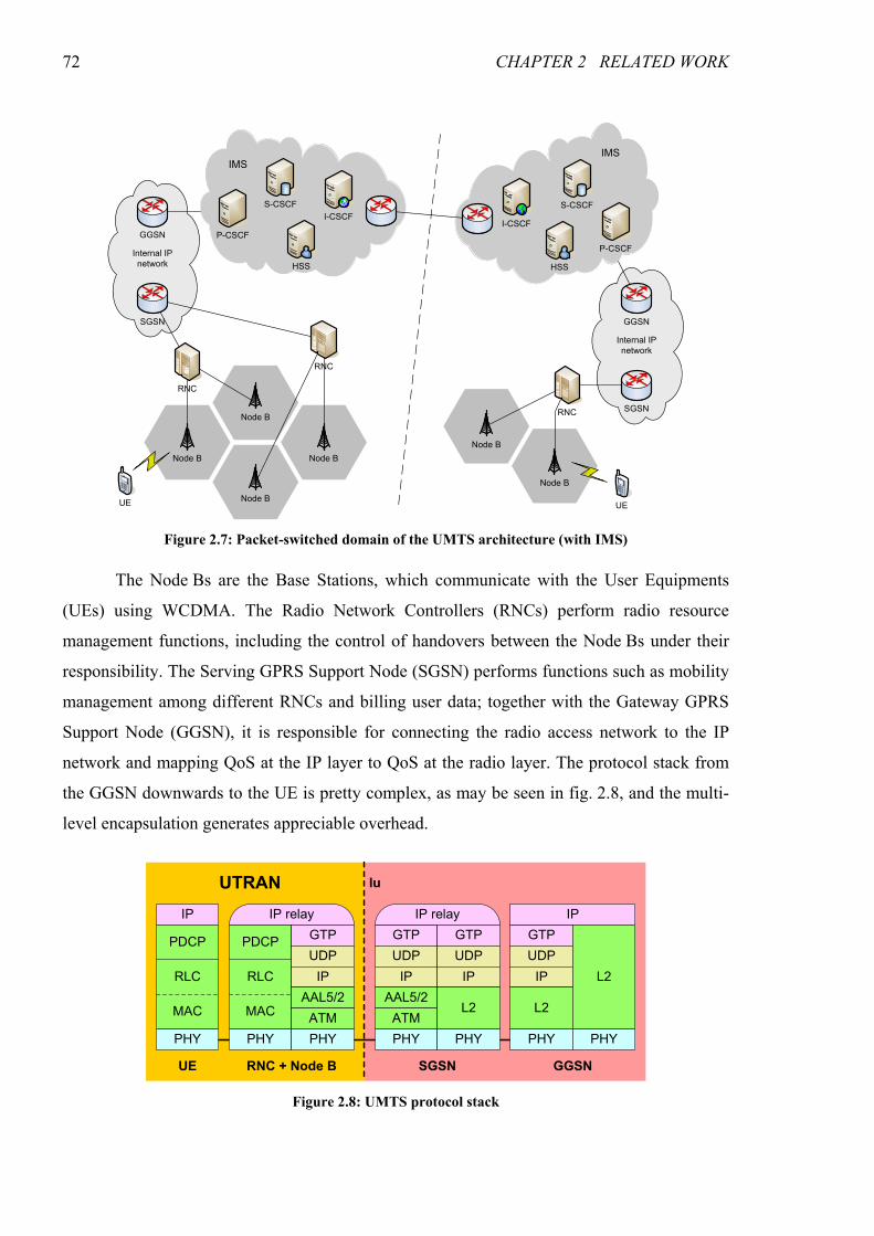
72 CHAPTER 2 RELATED WORK
The Node Bs are the Base Stations, which communicate with the User Equipments
(UEs) using WCDMA. The Radio Network Controllers (RNCs) perform radio resource
management functions, including the control of handovers between the Node Bs under their
responsibility. The Serving GPRS Support Node (SGSN) performs functions such as mobility
management among different RNCs and billing user data; together with the Gateway GPRS
Support Node (GGSN), it is responsible for connecting the radio access network to the IP
network and mapping QoS at the IP layer to QoS at the radio layer. The protocol stack from
the GGSN downwards to the UE is pretty complex, as may be seen in fig. 2.8, and the multi-
level encapsulation generates appreciable overhead.
Node B
Node B
Node BUE
Internal IP
network
GGSN
SGSN
HSS
I-CSCF
S-CSCF
P-CSCF
HSS
I-CSCF
S-CSCF
P-CSCF
Internal IP
network
GGSN
IMSIMS
Node B
Node B
UE
SGSNRNC
RNC
Node B
RNC
Figure 2.7: Packet-switched domain of the UMTS architecture (with IMS)
IP
PHY
PDCP
RLC
MAC
PHY
PDCP
RLC
MAC
IP relay
GTP
UDP
IP
AAL5/2
ATM
PHY
UTRAN
UE RNC + Node B
GTP
UDP
IP
AAL5/2
ATM
PHY
IP relay
GTP
UDP
IP
L2
PHY
SGSN
GTP
UDP
IP
L2
PHY
IP
L2
PHY
GGSN
Iu
Figure 2.8: UMTS protocol stack
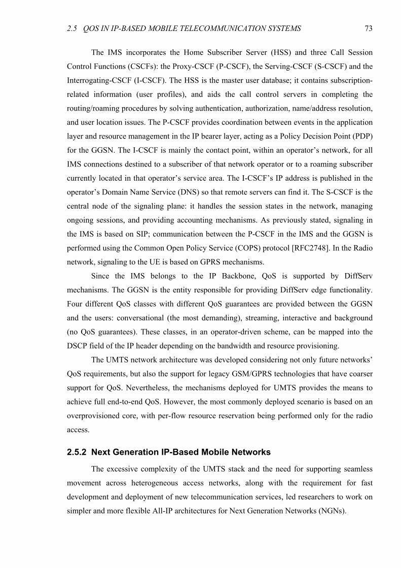
2.5 QOS IN IP-BASED MOBILE TELECOMMUNICATION SYSTEMS 73
The IMS incorporates the Home Subscriber Server (HSS) and three Call Session
Control Functions (CSCFs): the Proxy-CSCF (P-CSCF), the Serving-CSCF (S-CSCF) and the
Interrogating-CSCF (I-CSCF). The HSS is the master user database; it contains subscription-
related information (user profiles), and aids the call control servers in completing the
routing/roaming procedures by solving authentication, authorization, name/address resolution,
and user location issues. The P-CSCF provides coordination between events in the application
layer and resource management in the IP bearer layer, acting as a Policy Decision Point (PDP)
for the GGSN. The I-CSCF is mainly the contact point, within an operator’s network, for all
IMS connections destined to a subscriber of that network operator or to a roaming subscriber
currently located in that operator’s service area. The I-CSCF’s IP address is published in the
operator’s Domain Name Service (DNS) so that remote servers can find it. The S-CSCF is the
central node of the signaling plane: it handles the session states in the network, managing
ongoing sessions, and providing accounting mechanisms. As previously stated, signaling in
the IMS is based on SIP; communication between the P-CSCF in the IMS and the GGSN is
performed using the Common Open Policy Service (COPS) protocol [RFC2748]. In the Radio
network, signaling to the UE is based on GPRS mechanisms.
Since the IMS belongs to the IP Backbone, QoS is supported by DiffServ
mechanisms. The GGSN is the entity responsible for providing DiffServ edge functionality.
Four different QoS classes with different QoS guarantees are provided between the GGSN
and the users: conversational (the most demanding), streaming, interactive and background
(no QoS guarantees). These classes, in an operator-driven scheme, can be mapped into the
DSCP field of the IP header depending on the bandwidth and resource provisioning.
The UMTS network architecture was developed considering not only future networks’
QoS requirements, but also the support for legacy GSM/GPRS technologies that have coarser
support for QoS. Nevertheless, the mechanisms deployed for UMTS provides the means to
achieve full end-to-end QoS. However, the most commonly deployed scenario is based on an
overprovisioned core, with per-flow resource reservation being performed only for the radio
access.
2.5.2 Next Generation IP-Based Mobile Networks
The excessive complexity of the UMTS stack and the need for supporting seamless
movement across heterogeneous access networks, along with the requirement for fast
development and deployment of new telecommunication services, led researchers to work on
simpler and more flexible All-IP architectures for Next Generation Networks (NGNs).
74 CHAPTER 2 RELATED WORK
Envisioning an evolution of the 3G mobile and wireless infrastructure towards the
Internet, the Moby Dick project [MobyDick] has defined, implemented, and evaluated an
IPv6-based, mobility-enabled QoS architecture for heterogeneous networks, based on IETF’s
QoS models, Mobile IPv6, and Authentication, Authorization, Accounting and Charging
(AAAC) framework. The proposed architecture [Marques03] is centered on QoS Brokers and
their cooperation with an AAAC system. The architecture uses IPv6 as a convergence layer,
providing a common ground for the use of different access technologies. Mobility
management is performed at layer 3, using Mobile IPv6 with Fast Handover (FHO)
extensions, and is controlled by the QoS Brokers. The FHO support uses a “make before
break” approach, where resources are reserved on the new cell before disconnecting from the
previous one; moreover, packets are bicast to both cells until the handover is finished. The use
of QoS-aware Fast Handovers, combined with the use of context transfer, allows for seamless
mobility across different access technologies.
QoS on the data plane is provided by DiffServ. On the control plane, QoS support is
based on the concept of services. Users subscribe to SLAs consisting on sets of services with
high-level descriptions (e.g., telephony); these services are mapped by the operators into
network services (consisting on a traffic class, identified by the DSCP, and associated rate
limits). The set of subscribed network services constitutes the Network View of the User
Profile (NVUP). QoS Brokers use the NVUP for admission control (combined with
information on available resources) and for configuring the Access Routers (ARs). QoS
signaling is implicit and performed in-band. In order to request a service, the user starts
sending packets marked with the corresponding DSCP. The first packet is intercepted at the
AR, triggering an admission control request to the QoS Broker; if the request is accepted, the
AR is instructed to let the packets marked with that DSCP flow to/from the requesting Mobile
Terminal. For termination, every network service has an associated timeout: if no packets
with the corresponding DSCP are sent or received during this timeout period, the network
elements will automatically free the resources and stop accounting usage of the service.
Resource management in the access is, thus, performed per (Terminal, Service). In the core,
resources are managed by aggregate, independently of the individual flows, using an
overprovisioning approach.
The Moby Dick architecture provides an integrated solution addressing most relevant
issues for NGN operators (AAAC, QoS, mobility, security). However, QoS is relatively
coarse-grained (it allows only one instance of a network service per terminal at any time), and
2.6 SIP — SESSION INITIATION PROTOCOL 75
relies on overprovisioning outside the access link. The network part of the DAIDALOS
architecture introduced in chapter 5 is an evolution of the Moby Dick architecture.
2.6 SIP — Session Initiation Protocol
The Session Initiation Protocol (SIP) [RFC3261] is an application-layer signaling
protocol for establishing, modifying and terminating sessions between two or more
participants over IP networks. These sessions include Internet telephone calls, multimedia
distribution, and multimedia conferences. SIP can be used to invite participants to already
existing sessions, such as multicast conferences, and also to add or remove media to/from an
existing session.
Originally developed around 1996 from the merging of two proposed protocols for the
multimedia conference control (the Session Invitation Protocol and the Simple Conference
Invitation Protocol), SIP has been very actively developed due to the enormous interest it
generated, resulting from the great promises of IP telephony. SIP was first standardized in
[RFC2543], and is now specified by [RFC3261] along with a large number of extensions. The
adoption of SIP by the 3GPP as a mandatory protocol for signaling in the IMS was not only a
landmark for establishing it as the most prominent protocol in IP telephony, but also a major
drive for standardizing the extensions required for mobile telephony.
2.6.1 Protocol Overview
SIP is a protocol for controlling sessions consisting of one or more media streams
(audio, video, or any other IP-based communication mechanism). It is a text-based request/
response protocol, heavily drawing from the Hypertext Transfer Protocol (HTTP) [RFC2616]:
SIP messages consist on a request or status line, header fields and an optional Multipurpose
Internet Mail Extensions (MIME) body. A notable difference is that SIP can use different
transport protocols, including UDP, using retransmissions for ensuring request reliability over
unreliable protocols.
SIP endpoints are addressed by Uniform Resource Identifiers (URIs), usually sip or
sips, similar to email addresses (e.g., sip:[email protected]). SIP requests contain a
source address (From header) and two destination addresses, one with the original, logical
destination (To header) and the other with the current destination (URI in the request line),
which may change as a result of the user location (call routing) process. Moreover, the
Contact header specifies the address where future requests should be sent.
SIP defines four logical entities (user agents, registrars, redirect servers and proxies),
and an abstract location service; it also requires DNS support for translating names to IP
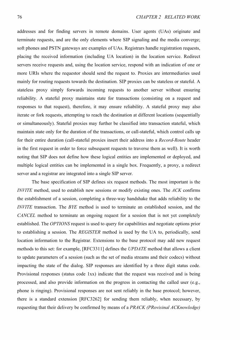
76 CHAPTER 2 RELATED WORK
addresses and for finding servers in remote domains. User agents (UAs) originate and
terminate requests, and are the only elements where SIP signaling and the media converge;
soft phones and PSTN gateways are examples of UAs. Registrars handle registration requests,
placing the received information (including UA location) in the location service. Redirect
servers receive requests and, using the location service, respond with an indication of one or
more URIs where the requestor should send the request to. Proxies are intermediaries used
mainly for routing requests towards the destination. SIP proxies can be stateless or stateful. A
stateless proxy simply forwards incoming requests to another server without ensuring
reliability. A stateful proxy maintains state for transactions (consisting on a request and
responses to that request), therefore, it may ensure reliability. A stateful proxy may also
iterate or fork requests, attempting to reach the destination at different locations (sequentially
or simultaneously). Stateful proxies may further be classified into transaction stateful, which
maintain state only for the duration of the transactions, or call-stateful, which control calls up
for their entire duration (call-stateful proxies insert their address into a Record-Route header
in the first request in order to force subsequent requests to traverse them as well). It is worth
noting that SIP does not define how these logical entities are implemented or deployed, and
multiple logical entities can be implemented in a single box. Frequently, a proxy, a redirect
server and a registrar are integrated into a single SIP server.
The base specification of SIP defines six request methods. The most important is the
INVITE method, used to establish new sessions or modify existing ones. The ACK confirms
the establishment of a session, completing a three-way handshake that adds reliability to the
INVITE transaction. The BYE method is used to terminate an established session, and the
CANCEL method to terminate an ongoing request for a session that is not yet completely
established. The OPTIONS request is used to query for capabilities and negotiate options prior
to establishing a session. The REGISTER method is used by the UA to, periodically, send
location information to the Registrar. Extensions to the base protocol may add new request
methods to this set: for example, [RFC3311] defines the UPDATE method that allows a client
to update parameters of a session (such as the set of media streams and their codecs) without
impacting the state of the dialog. SIP responses are identified by a three digit status code.
Provisional responses (status code 1xx) indicate that the request was received and is being
processed, and also provide information on the progress in contacting the called user (e.g.,
phone is ringing). Provisional responses are not sent reliably in the base protocol; however,
there is a standard extension [RFC3262] for sending them reliably, when necessary, by
requesting that their delivery be confirmed by means of a PRACK (PRovisinal ACKnowledge)
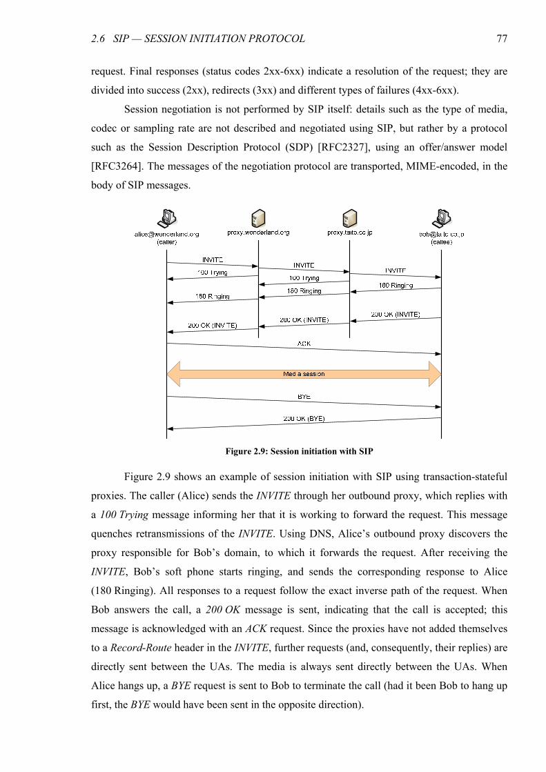
2.6 SIP — SESSION INITIATION PROTOCOL 77
request. Final responses (status codes 2xx-6xx) indicate a resolution of the request; they are
divided into success (2xx), redirects (3xx) and different types of failures (4xx-6xx).
Session negotiation is not performed by SIP itself: details such as the type of media,
codec or sampling rate are not described and negotiated using SIP, but rather by a protocol
such as the Session Description Protocol (SDP) [RFC2327], using an offer/answer model
[RFC3264]. The messages of the negotiation protocol are transported, MIME-encoded, in the
body of SIP messages.
Figure 2.9 shows an example of session initiation with SIP using transaction-stateful
proxies. The caller (Alice) sends the INVITE through her outbound proxy, which replies with
a 100 Trying message informing her that it is working to forward the request. This message
quenches retransmissions of the INVITE. Using DNS, Alice’s outbound proxy discovers the
proxy responsible for Bob’s domain, to which it forwards the request. After receiving the
INVITE, Bob’s soft phone starts ringing, and sends the corresponding response to Alice
(180 Ringing). All responses to a request follow the exact inverse path of the request. When
Bob answers the call, a 200 OK message is sent, indicating that the call is accepted; this
message is acknowledged with an ACK request. Since the proxies have not added themselves
to a Record-Route header in the INVITE, further requests (and, consequently, their replies) are
directly sent between the UAs. The media is always sent directly between the UAs. When
Alice hangs up, a BYE request is sent to Bob to terminate the call (had it been Bob to hang up
first, the BYE would have been sent in the opposite direction).
Figure 2.9: Session initiation with SIP
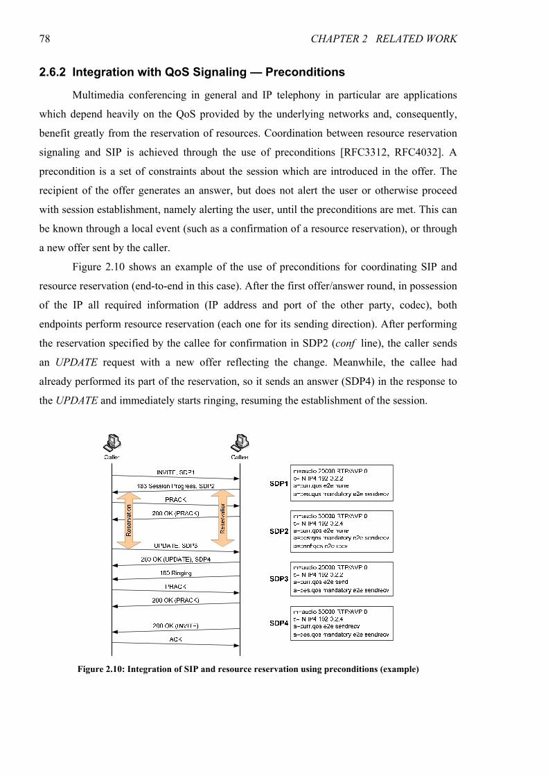
78 CHAPTER 2 RELATED WORK
2.6.2 Integration with QoS Signaling — Preconditions
Multimedia conferencing in general and IP telephony in particular are applications
which depend heavily on the QoS provided by the underlying networks and, consequently,
benefit greatly from the reservation of resources. Coordination between resource reservation
signaling and SIP is achieved through the use of preconditions [RFC3312, RFC4032]. A
precondition is a set of constraints about the session which are introduced in the offer. The
recipient of the offer generates an answer, but does not alert the user or otherwise proceed
with session establishment, namely alerting the user, until the preconditions are met. This can
be known through a local event (such as a confirmation of a resource reservation), or through
a new offer sent by the caller.
Figure 2.10 shows an example of the use of preconditions for coordinating SIP and
resource reservation (end-to-end in this case). After the first offer/answer round, in possession
of the IP all required information (IP address and port of the other party, codec), both
endpoints perform resource reservation (each one for its sending direction). After performing
the reservation specified by the callee for confirmation in SDP2 (conf line), the caller sends
an UPDATE request with a new offer reflecting the change. Meanwhile, the callee had
already performed its part of the reservation, so it sends an answer (SDP4) in the response to
the UPDATE and immediately starts ringing, resuming the establishment of the session.
Figure 2.10: Integration of SIP and resource reservation using preconditions (example)
2.6 SIP — SESSION INITIATION PROTOCOL 79
2.6.3 SIP and Mobility
SIP has built-in support for application layer terminal mobility management
[Wedlund99, Schulzrinne00]. Pre-session mobility is trivially provided by the location
service: the terminal simply re-registers with its “home” registrar every time it obtains a new
IP address. Mid-session mobility is supported by sending a re-INVITE to the other party,
informing it of the new IP address. This re-INVITE is routed much faster than the original
INVITE, since the moving terminal already has the direct contact of the other party, and only
proxies that added themselves to the Record-Route header will be traversed.
The use of SIP for mobility management, however, trades generality for ease of
deployment. SIP mobility is not suitable for TCP connections, as they depend on the IP
addresses of both endpoints. This, and the fact that different procedures must be used for SIP
and non-SIP sessions, constitutes a disadvantage of SIP-based mobility compared to a general
layer 3 solution like Mobile IP (MIP) [RFC3344] or Mobile IPv6 (MIPv6) [RFC3775].
However, the duplication of mobility management functions in the network and application
layers leads to inefficiency issues. The following paragraphs describe some proposals for
different degrees of integration of SIP and MIP (v4 and v6), aimed at providing improved
mobility management capabilities.
Jung et al. [Jung03] proposed the use of integrated mobility agents for SIP and
MIP(v4). Some of the MIP functions (like binding refreshments) are transposed to SIP, and
mobility is communicated to the correspondent nodes (CNs) via re-INVITE requests. This
approach imposes different handover procedures for SIP and non-SIP sessions (UDP or TCP),
and the security issues of establishing bindings with CNs via SIP were not addressed.
Politis et al. [Politis03] proposed a hybrid SIP/MIP(v4) scheme for inter-domain
mobility. Their approach avoids the IP-in-IP MIP encapsulation for SIP sessions, but not for
non-SIP ones, for which the handovers are managed by MIP. Their work mostly concerns
mid-session mobility which, in our case, is handled by a modified MIPv6 with Fast Handover
extensions. Moreover, the encapsulation problem is mitigated in MIPv6 by the use of routing
optimization.
Wang et al. [Wang03, Wang04] proposed an integrated SIP-MIP mobility
management architecture, where MIP and SIP agents are broken down into functional blocks
and then integrated, without duplication, into unified Home and Foreign Mobility Servers
(HMS/FMS), thus avoiding redundancy. Their proposal mostly intends to solve the problems
associated with different types of mid-session mobility that in our case are addressed at the
80 CHAPTER 2 RELATED WORK
layer 3. Moreover, their architecture is different from ours in that it requires one FMS per
(access) network.
An interesting problem that none of these proposals has addressed concerns the
inefficiency issues resulting from the integration of end-to-end resource reservation with
session signaling in mobile scenarios.
2.7 Summary
This chapter provided some background for the work described in this thesis, with an
overview of the most relevant related work. We described the different functions that can be
used as building blocks for QoS provisioning. We introduced the two major QoS frameworks
proposed by the IETF (IntServ and DiffServ) and gave an overview of the most important
proposals for QoS models aimed at the conciliation of the benefits of IntServ (per-flow
guarantees) and DiffServ (scalability); the proposals were grouped according to the central
concept employed — alternative signaling model, flow aggregation, elimination of state in the
core, or centralization of control plane functions in Bandwidth Brokers. We also described
proposed solutions for the two orthogonal problems of inter-domain QoS — inter-domain
resource reservation and inter-domain QoS routing. With respect to QoS in IP-based mobile
networks, we gave an overview of UMTS, focusing on the packet-switched domain, and
pointed out directions for the next generation networks. Finally, we introduced the Session
Initiation Protocol, central to UMTS’ IP Multimedia Subsystem and the strongest contender
in the field of multimedia session establishment and control protocols for the Internet; we
gave an overview of the protocol, of its coordination with network resource reservation
signaling, and its relation with mobility.
81
CHAPTER 3
EVALUATION OF RSVP RESERVATION AGGREGATION
Even though the RSVP Reservation Aggregation (RSVPRAgg) [RFC3175] model was
generally considered the best candidate for a scalable replacement of RSVP/IntServ
[RFC2205, RFC1633] in high-speed core networks, no performance study had been carried
out on a packet network simulator, though numerical simulations for aggregation in general
did exist [Sargento02]. In fact, no implementation of the model which could be used to
perform such study was available for any packet network simulator. This state of affairs,
along with the need for such implementation to perform the comparison with the Scalable
Reservation-Based QoS architecture presented in the next chapter, led us to the development
of an RSVPRAgg extension module for the ns-2 simulator [NS2], publicly available for
download from [PriorNS], and to the simulation study presented in this chapter and originally
published in [Prior04c].
In this chapter we present an overview of the RSVPRAgg QoS model, its
implementation and performance evaluation. We begin with an overview of the model and its
principles in the next section. Section 3.2 describes the implementation in more detail,
regarding message processing and the bandwidth management policy for aggregates, which is
considered out of the scope of [RFC3175]. Some particularities of our implementation and
limitations of the model are also discussed in this section. A performance evaluation, based on
simulation results, is presented in section 3.3. We analyze the standard QoS parameters
(delay, jitter and packet loss ratio), as well as other parameters relevant to the performance
and scalability of the architecture, such as network resource utilization and the number of
82 CHAPTER 3 EVALUATION OF RSVP RESERVATION AGGREGATION
signaling messages processed at core nodes, and compare them to those obtained with the
standard RSVP/IntServ architecture in similar conditions. The results show that, while
RSVPRAgg is able to meet the QoS requirements of a controlled load class in a scalable way,
it suffers from underutilization of network resources. With these simulations we also
evaluated the influence of some tunable parameters: the bulk size and the hysteresis time.
Based on the results we derive some guidelines for setting these parameters. Finally, section
3.4 presents the conclusions of the evaluation herein performed.
3.1 Overview of RSVP Reservation Aggregation
The RSVP Reservation Aggregation model [RFC3175] preconizes the use of a single
RSVP reservation to aggregate different RSVP reservations inside an aggregation region,
provided they share the ingress and egress nodes (aggregator and deaggregator) and belong to
the same traffic class. Each aggregate reservation has a token bucket specification whose rate
and bucket depth are larger or equal to the summed values of the individual end-to-end RSVP
reservations using it. Furthermore, aggregate reservations are updated in quantities much
larger than average individual flows’ token bucket specifications, termed bulks. The
establishment of a smaller number of aggregate reservations on behalf of a larger number of
end-to-end ones, combined with an update rate much lower than the reservation
setup/termination/modification rate of the end-to-end flows, allows for a considerable
reduction in the amount of state stored and the number of signaling messages processed at the
interior nodes of the aggregation region. Edge nodes, on the other hand, must keep state
information and process signaling messages for both end-to-end and aggregate reservations.
Therefore, the amount of state and message processing overhead at the edge nodes is
somewhat higher than in regular RSVP.
In order to hide end-to-end RSVP messages from RSVP-capable routers inside the
aggregation region, the aggregator changes the IP protocol number field of some RSVP
messages (namely Path, PathTear and ResvConf) to RSVP-E2E-IGNORE. These messages
are forwarded as normal IP datagrams inside the aggregation region, meaning they are not
processed and no corresponding state is stored. At the deaggregator, the IP protocol number
field is restored to RSVP. The previous hop perceived (and stored) by the deaggregator for
these messages is the aggregator. This implies that the protocol number for other end-to-end
RSVP messages needs not be changed, as they are unicast from RSVP hop to RSVP hop1.
1 That is, are directly sent from one hop to the following, using their addresses as source and destination IP.
3.1 OVERVIEW OF RSVP RESERVATION AGGREGATION 83
The use of DiffServ (Differentiated Services) [RFC2475] mechanisms for the
classification and scheduling of traffic supported by aggregate reservations makes the amount
of classification and scheduling state stored inside the aggregation region independent not
only of the number of end-to-end reservations but also of the number of aggregate
reservations. The process of classifying and scheduling packets inside the aggregation region
is, therefore, comparatively light in terms of required processing power.
Traffic covered by aggregate reservations is identified by one or more Differentiated
Services Code Points (DSCPs), corresponding to one or more Per-Hop Behaviors (PHBs) that
provide the required forwarding treatment. Different traffic classes are supported by having
more than one aggregate between each pair of ingress/egress routers. In this case, a different
DSCP (or DSCP set) and a different PHB (or PHB group) are assigned to each traffic class
(more than one DSCP set and PHB group may be assigned to a single traffic class in order to
achieve differentiation within that class).
Aggregate reservations are performed in a similar way to regular RSVP reservations,
only using a different session specification which carries the IP address of the deaggregator
and the (main) DSCP of the aggregate.
The main advantage of aggregating end-to-end reservations using the model briefly
described in the preceding paragraphs is a much enhanced scalability than is the case with
regular RSVP. This is due to (1) the much lighter packet classification and scheduling
procedures, (2) the reduced amount of state stored at the interior nodes and (3) the lower
number of signaling messages processed at these nodes. Another significant advantage of this
architecture is transparency: terminals and access domains do not need to be modified or even
know that core domains are using aggregation. At access domains, where scalability is not
such an important issue as it is in core domains, standard RSVP/IntServ is used.
The main disadvantage of the aggregation model is the underutilization of network
resources. In fact, there must be at least one aggregate (more if more than one service class is
supported) for each (aggregator, deaggregator) pair and, in order to reduce signaling
processing and profit from the resulting scalability enhancement, the bandwidth of each
aggregate must be updated in bulk quantities much larger than the average flow rate. The
bandwidth of the aggregates is, therefore, almost never fully utilized. The unused bandwidth
of all aggregates traversing a link adds up, meaning that there will be a significant amount of
wasted link capacity. The bulk size must, therefore, be chosen weighting the higher signaling
reduction from large bulk sizes against the increased network resource underutilization.
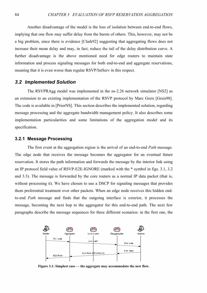
84 CHAPTER 3 EVALUATION OF RSVP RESERVATION AGGREGATION
Another disadvantage of the model is the loss of isolation between end-to-end flows,
implying that one flow may suffer delay from the bursts of others. This, however, may not be
a big problem, since there is evidence [Clark92] suggesting that aggregating flows does not
increase their mean delay and may, in fact, reduce the tail of the delay distribution curve. A
further disadvantage is the above mentioned need for edge routers to maintain state
information and process signaling messages for both end-to-end and aggregate reservations,
meaning that it is even worse than regular RSVP/IntServ in this respect.
3.2 Implemented Solution
The RSVPRAgg model was implemented in the ns-2.26 network simulator [NS2] as
an extension to an existing implementation of the RSVP protocol by Marc Greis [Greis98].
The code is available in [PriorNS]. This section describes the implemented solution, regarding
message processing and the aggregate bandwidth management policy. It also describes some
implementation particularities and some limitations of the aggregation model and its
specification.
3.2.1 Message Processing
The first event at the aggregation region is the arrival of an end-to-end Path message.
The edge node that receives the message becomes the aggregator for an eventual future
reservation. It stores the path information and forwards the message by the interior link using
an IP protocol field value of RSVP-E2E-IGNORE (marked with the * symbol in figs. 3.1, 3.2
and 3.3). The message is forwarded by the core routers as a normal IP data packet (that is,
without processing it). We have chosen to use a DSCP for signaling messages that provides
them preferential treatment over other packets. When an edge node receives this hidden end-
to-end Path message and finds that the outgoing interface is exterior, it processes the
message, becoming the next hop to the aggregator for this end-to-end path. The next few
paragraphs describe the message sequences for three different scenarios: in the first one, the
Figure 3.1: Simplest case — the aggregate may accommodate the new flow.
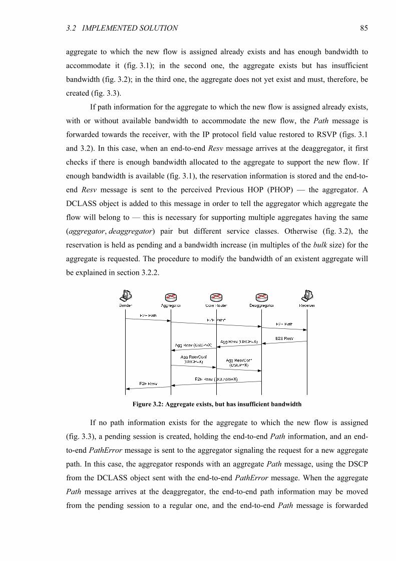
3.2 IMPLEMENTED SOLUTION 85
aggregate to which the new flow is assigned already exists and has enough bandwidth to
accommodate it (fig. 3.1); in the second one, the aggregate exists but has insufficient
bandwidth (fig. 3.2); in the third one, the aggregate does not yet exist and must, therefore, be
created (fig. 3.3).
If path information for the aggregate to which the new flow is assigned already exists,
with or without available bandwidth to accommodate the new flow, the Path message is
forwarded towards the receiver, with the IP protocol field value restored to RSVP (figs. 3.1
and 3.2). In this case, when an end-to-end Resv message arrives at the deaggregator, it first
checks if there is enough bandwidth allocated to the aggregate to support the new flow. If
enough bandwidth is available (fig. 3.1), the reservation information is stored and the end-to-
end Resv message is sent to the perceived Previous HOP (PHOP) — the aggregator. A
DCLASS object is added to this message in order to tell the aggregator which aggregate the
flow will belong to — this is necessary for supporting multiple aggregates having the same
(aggregator, deaggregator) pair but different service classes. Otherwise (fig. 3.2), the
reservation is held as pending and a bandwidth increase (in multiples of the bulk size) for the
aggregate is requested. The procedure to modify the bandwidth of an existent aggregate will
be explained in section 3.2.2.
If no path information exists for the aggregate to which the new flow is assigned
(fig. 3.3), a pending session is created, holding the end-to-end Path information, and an end-
to-end PathError message is sent to the aggregator signaling the request for a new aggregate
path. In this case, the aggregator responds with an aggregate Path message, using the DSCP
from the DCLASS object sent with the end-to-end PathError message. When the aggregate
Path message arrives at the deaggregator, the end-to-end path information may be moved
from the pending session to a regular one, and the end-to-end Path message is forwarded
Figure 3.2: Aggregate exists, but has insufficient bandwidth
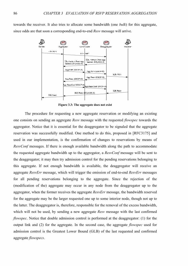
86 CHAPTER 3 EVALUATION OF RSVP RESERVATION AGGREGATION
towards the receiver. It also tries to allocate some bandwidth (one bulk) for this aggregate,
since odds are that soon a corresponding end-to-end Resv message will arrive.
The procedure for requesting a new aggregate reservation or modifying an existing
one consists on sending an aggregate Resv message with the requested flowspec towards the
aggregator. Notice that it is essential for the deaggregator to be signaled that the aggregate
reservation was successfully modified. One method to do this, proposed in [RFC3175] and
used in our implementation, is the confirmation of changes to reservations by means of
ResvConf messages. If there is enough available bandwidth along the path to accommodate
the requested aggregate bandwidth up to the aggregator, a ResvConf message will be sent to
the deaggregator; it may then try admission control for the pending reservations belonging to
this aggregate. If not enough bandwidth is available, the deaggregator will receive an
aggregate ResvErr message, which will trigger the emission of end-to-end ResvErr messages
for all pending reservations belonging to the aggregate. Since the rejection of the
(modification of the) aggregate may occur in any node from the deaggregator up to the
aggregator, when the former receives the aggregate ResvErr message, the bandwidth reserved
for the aggregate may be the larger requested one up to some interior node, though not up to
the latter. The deaggregator is, therefore, responsible for the removal of the excess bandwidth,
which will not be used, by sending a new aggregate Resv message with the last confirmed
flowspec. Notice that double admission control is performed at the deaggregator: (1) for the
output link and (2) for the aggregate. In the second case, the aggregate flowspec used for
admission control is the Greatest Lower Bound (GLB) of the last requested and confirmed
aggregate flowspecs.
Figure 3.3: The aggregate does not exist
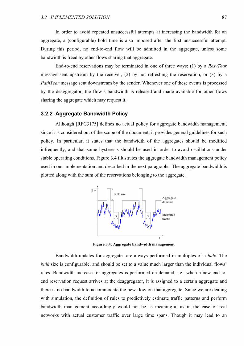
3.2 IMPLEMENTED SOLUTION 87
In order to avoid repeated unsuccessful attempts at increasing the bandwidth for an
aggregate, a (configurable) hold time is also imposed after the first unsuccessful attempt.
During this period, no end-to-end flow will be admitted in the aggregate, unless some
bandwidth is freed by other flows sharing that aggregate.
End-to-end reservations may be terminated in one of three ways: (1) by a ResvTear
message sent upstream by the receiver, (2) by not refreshing the reservation, or (3) by a
PathTear message sent downstream by the sender. Whenever one of these events is processed
by the deaggregator, the flow’s bandwidth is released and made available for other flows
sharing the aggregate which may request it.
3.2.2 Aggregate Bandwidth Policy
Although [RFC3175] defines no actual policy for aggregate bandwidth management,
since it is considered out of the scope of the document, it provides general guidelines for such
policy. In particular, it states that the bandwidth of the aggregates should be modified
infrequently, and that some hysteresis should be used in order to avoid oscillations under
stable operating conditions. Figure 3.4 illustrates the aggregate bandwidth management policy
used in our implementation and described in the next paragraphs. The aggregate bandwidth is
plotted along with the sum of the reservations belonging to the aggregate.
Bandwidth updates for aggregates are always performed in multiples of a bulk. The
bulk size is configurable, and should be set to a value much larger than the individual flows’
rates. Bandwidth increase for aggregates is performed on demand, i.e., when a new end-to-
end reservation request arrives at the deaggregator, it is assigned to a certain aggregate and
there is no bandwidth to accommodate the new flow on that aggregate. Since we are dealing
with simulation, the definition of rules to predictively estimate traffic patterns and perform
bandwidth management accordingly would not be as meaningful as in the case of real
networks with actual customer traffic over large time spans. Though it may lead to an
Aggregate
demand
Measured
traffic
Bw
Bulk size
τ τ
t Figure 3.4: Aggregate bandwidth management
88 CHAPTER 3 EVALUATION OF RSVP RESERVATION AGGREGATION
increased reservation setup delay, this reactive policy tends to increase network utilization,
since it leaves more bandwidth available for other aggregates which will hold actual traffic.
The sole exception to the reactive policy rule happens at the creation time of a new aggregate.
Since it is triggered by the reception of a Path message, odds are that a request for a
reservation assigned to the new aggregate will soon be received. By predictively allocating
some bandwidth (one bulk) to the aggregate, it is possible to reduce the setup time for that
end-to-end reservation.
Bandwidth reduction for aggregates is not performed immediately when it ceases to be
needed. Instead, it is delayed until the excess bulk has not been in use for a certain,
configurable, time period τ. This hysteresis mechanism is intended to avoid unnecessary
message processing at the interior nodes by successively increasing and decreasing the
bandwidth in a stable operating point around a multiple of the bulk size. If, at a certain instant,
the wasted bandwidth of an aggregate exceeds two bulks, though, bandwidth reduction is
performed immediately, leaving only one excess bulk and restarting the hysteresis timer.
In order to avoid repeatedly trying to increase an aggregate’s bandwidth without
success, leading to unnecessary message processing at the core (interior) nodes, a
configurable hold time was also implemented during which no aggregate bandwidth increase
will be tried in response to the arrival of a new end-to-end reservation request assigned to that
particular aggregate. During that time period, new end-to-end reservation requests will either
be accepted immediately, which may happen if other flows belonging to the same aggregate
were terminated leaving some bandwidth available, or they will be rejected.
3.2.3 Particularities and Limitations
Our ns-2 implementation of the aggregation model has some particularities and
limitations which will be discussed in the next paragraphs. Of these, some are due to
simplifications in our extension to RSVP/ns, while others are limitations of the specification
of the RSVP reservation aggregation model itself.
One limitation of the aggregation model is related to the Guaranteed Service (GS).
With aggregation, the rate-delay coupling assumption is not valid — all flows aggregated into
a single queue share the same delay bounds. Due to the disparity of these bounds, GS flows
sharing the same aggregator and deaggregator nodes cannot be assigned to a single aggregate;
instead, they must be partitioned into a set of aggregates, each corresponding to a different
delay bound [Schmitt99]. Dynamically partitioning the flows into aggregates would be too
complex and generate too much signaling to be scalable. One must, therefore, resort to static
partitioning, leading to sub-optimal results. This sub-optimal partitioning inevitably leads to
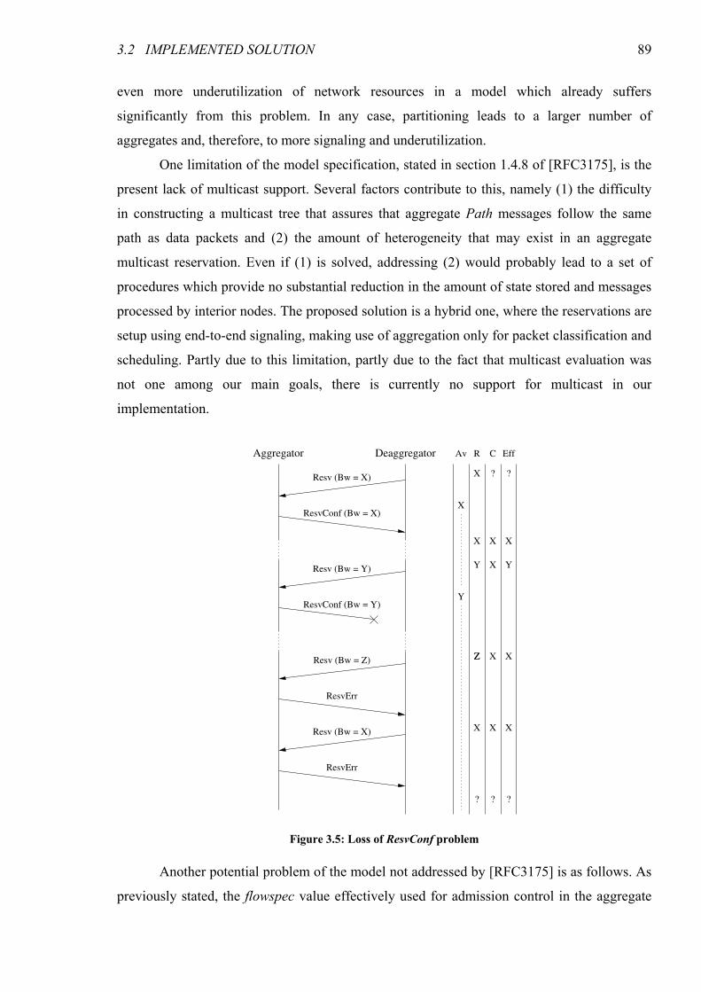
3.2 IMPLEMENTED SOLUTION 89
even more underutilization of network resources in a model which already suffers
significantly from this problem. In any case, partitioning leads to a larger number of
aggregates and, therefore, to more signaling and underutilization.
One limitation of the model specification, stated in section 1.4.8 of [RFC3175], is the
present lack of multicast support. Several factors contribute to this, namely (1) the difficulty
in constructing a multicast tree that assures that aggregate Path messages follow the same
path as data packets and (2) the amount of heterogeneity that may exist in an aggregate
multicast reservation. Even if (1) is solved, addressing (2) would probably lead to a set of
procedures which provide no substantial reduction in the amount of state stored and messages
processed by interior nodes. The proposed solution is a hybrid one, where the reservations are
setup using end-to-end signaling, making use of aggregation only for packet classification and
scheduling. Partly due to this limitation, partly due to the fact that multicast evaluation was
not one among our main goals, there is currently no support for multicast in our
implementation.
Another potential problem of the model not addressed by [RFC3175] is as follows. As
previously stated, the flowspec value effectively used for admission control in the aggregate
DeaggregatorAggregator
Resv (Bw = X)
ResvConf (Bw = X)
Resv (Bw = Y)
ResvConf (Bw = Y)
Resv (Bw = Z)
ResvErr
Av R C Eff
X ? ?
X X X
XY
X
Y
ZZ X X
X X X
Y
Resv (Bw = X)
ResvErr
? ? ?
Figure 3.5: Loss of ResvConf problem
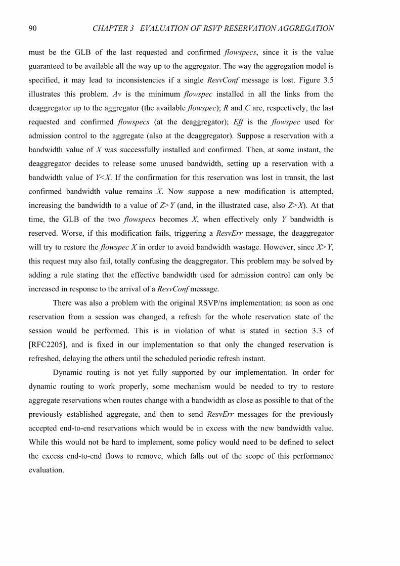
90 CHAPTER 3 EVALUATION OF RSVP RESERVATION AGGREGATION
must be the GLB of the last requested and confirmed flowspecs, since it is the value
guaranteed to be available all the way up to the aggregator. The way the aggregation model is
specified, it may lead to inconsistencies if a single ResvConf message is lost. Figure 3.5
illustrates this problem. Av is the minimum flowspec installed in all the links from the
deaggregator up to the aggregator (the available flowspec); R and C are, respectively, the last
requested and confirmed flowspecs (at the deaggregator); Eff is the flowspec used for
admission control to the aggregate (also at the deaggregator). Suppose a reservation with a
bandwidth value of X was successfully installed and confirmed. Then, at some instant, the
deaggregator decides to release some unused bandwidth, setting up a reservation with a
bandwidth value of Y<X. If the confirmation for this reservation was lost in transit, the last
confirmed bandwidth value remains X. Now suppose a new modification is attempted,
increasing the bandwidth to a value of Z>Y (and, in the illustrated case, also Z>X). At that
time, the GLB of the two flowspecs becomes X, when effectively only Y bandwidth is
reserved. Worse, if this modification fails, triggering a ResvErr message, the deaggregator
will try to restore the flowspec X in order to avoid bandwidth wastage. However, since X>Y,
this request may also fail, totally confusing the deaggregator. This problem may be solved by
adding a rule stating that the effective bandwidth used for admission control can only be
increased in response to the arrival of a ResvConf message.
There was also a problem with the original RSVP/ns implementation: as soon as one
reservation from a session was changed, a refresh for the whole reservation state of the
session would be performed. This is in violation of what is stated in section 3.3 of
[RFC2205], and is fixed in our implementation so that only the changed reservation is
refreshed, delaying the others until the scheduled periodic refresh instant.
Dynamic routing is not yet fully supported by our implementation. In order for
dynamic routing to work properly, some mechanism would be needed to try to restore
aggregate reservations when routes change with a bandwidth as close as possible to that of the
previously established aggregate, and then to send ResvErr messages for the previously
accepted end-to-end reservations which would be in excess with the new bandwidth value.
While this would not be hard to implement, some policy would need to be defined to select
the excess end-to-end flows to remove, which falls out of the scope of this performance
evaluation.
3.3 PERFORMANCE ANALYSIS 91
3.3 Performance Analysis
In this section we evaluate the performance of the RSVP Reservation Aggregation
architecture based on results from several different sets of simulations. The obtained results
are compared against those of simulations performed using the standard RSVP/IntServ
architecture with the same (dumbbell) topology. We analyze the standard QoS parameters
(delay, jitter and packet loss ratio), the network resource utilization at the core link, and the
reservation setup time. The number of signaling packets processed at the core is also analyzed
in order to ascertain the scalability of the architecture and the improvement over standard
RSVP.
Although admission control for aggregates must be parameter-based (PBAC),
admission control for flows inside aggregates may be either parameter- or measurement-based
(MBAC)2. We performed simulations with PBAC and MBAC. In the RSVP/IntServ
simulations we used PBAC.
Figure 3.6 shows the topology used in these simulations. It consists of a transit (core)
domain, TD, and 6 access domains, AD1–AD6. Each terminal in the access domains
simulates a set of terminals. The bandwidth of the links in the transit domain and the
interconnections between the transit and the access domains is 10 Mbps. The propagation
delay is 2 ms in the transit domain and 1 ms in the interconnections between domains. There
are up to 9 different aggregates in the link between C1 and C2, since there are 3 edge routers
connected to C1 and other 3 connected to C2. The bandwidth assigned to the Controlled Load
(CL) class is 7 Mbps. The bandwidth assigned to signaling traffic is 1 Mbps. Notice that,
although this seems very high, it is only an upper limit. The unused remaining 2 Mbps, as
2 The admission control mechanisms are described Appendix A.
C1 C2
E1
E2
E3
E5
E4
E6
A1
A1
A1
A1
A1
A1
T1
T1
T2
T1
T1
T1
T2
T1
Access Domain 1
AD2
AD3
AD5
AD4
AD6
Transit Domain(aggregation region)
Figure 3.6: Simulation topology for the evaluation of RSVP Reservation Aggregation
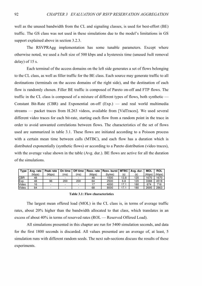
92 CHAPTER 3 EVALUATION OF RSVP RESERVATION AGGREGATION
well as the unused bandwidth from the CL and signaling classes, is used for best-effort (BE)
traffic. The GS class was not used in these simulations due to the model’s limitations in GS
support explained above in section 3.2.3.
The RSVPRAgg implementation has some tunable parameters. Except where
otherwise noted, we used a bulk size of 500 kbps and a hysteresis time (unused bulk removal
delay) of 15 s.
Each terminal of the access domains on the left side generates a set of flows belonging
to the CL class, as well as filler traffic for the BE class. Each source may generate traffic to all
destinations (terminals on the access domains of the right side), and the destination of each
flow is randomly chosen. Filler BE traffic is composed of Pareto on-off and FTP flows. The
traffic in the CL class is composed of a mixture of different types of flows, both synthetic —
Constant Bit-Rate (CBR) and Exponential on-off (Exp.) — and real world multimedia
streams — packet traces from H.263 videos, available from [VidTraces]. We used several
different video traces for each bit-rate, starting each flow from a random point in the trace in
order to avoid unwanted correlations between flows. The characteristics of the set of flows
used are summarized in table 3.1. These flows are initiated according to a Poisson process
with a certain mean time between calls (MTBC), and each flow has a duration which is
distributed exponentially (synthetic flows) or according to a Pareto distribution (video traces),
with the average value shown in the table (Avg. dur.). BE flows are active for all the duration
of the simulations.
The largest mean offered load (MOL) in the CL class is, in terms of average traffic
rates, about 20% higher than the bandwidth allocated to that class, which translates in an
excess of about 40% in terms of reserved rates (ROL — Reserved Offered Load).
All simulations presented in this chapter are run for 5400 simulation seconds, and data
for the first 1800 seconds is discarded. All values presented are an average of, at least, 5
simulation runs with different random seeds. The next sub-sections discuss the results of these
experiments.
Table 3.1: Flow characteristics
Type Avg. rate Peak rate On time Off time MTBC MOL ROL
(ms) (ms) (bytes) (s) (s)
CBR 48 - - - 48 1500 13.8 120 1670 1670Exp. 48 96 200 200 64 2500 6.8 120 3388 4518
Video 16 - - - 17 4000 17.1 180 674 716Video 64 - - - 68 8000 17.1 180 2695 2863
Resv. rate Resv. burst Avg. dur.
(kbps) (kbps) (kbps) (kbps) (kbps)
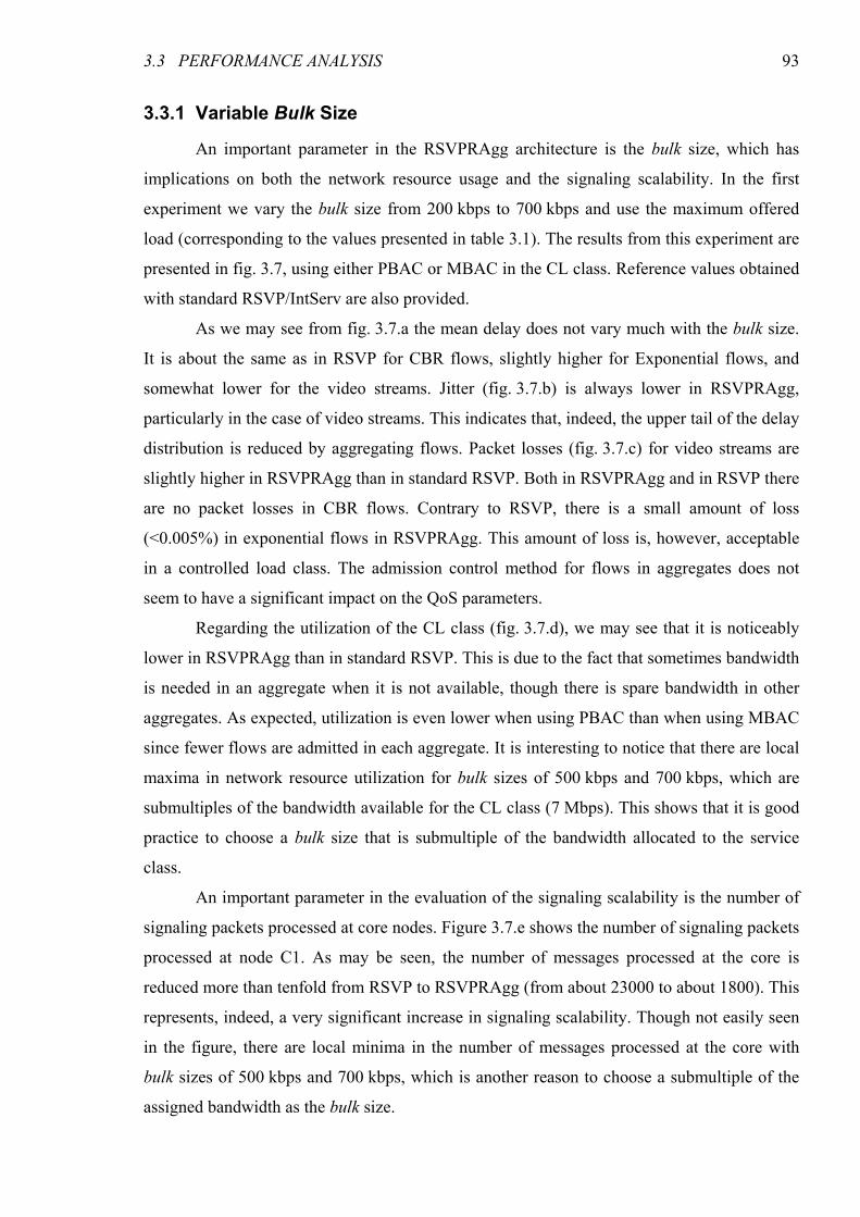
3.3 PERFORMANCE ANALYSIS 93
3.3.1 Variable Bulk Size
An important parameter in the RSVPRAgg architecture is the bulk size, which has
implications on both the network resource usage and the signaling scalability. In the first
experiment we vary the bulk size from 200 kbps to 700 kbps and use the maximum offered
load (corresponding to the values presented in table 3.1). The results from this experiment are
presented in fig. 3.7, using either PBAC or MBAC in the CL class. Reference values obtained
with standard RSVP/IntServ are also provided.
As we may see from fig. 3.7.a the mean delay does not vary much with the bulk size.
It is about the same as in RSVP for CBR flows, slightly higher for Exponential flows, and
somewhat lower for the video streams. Jitter (fig. 3.7.b) is always lower in RSVPRAgg,
particularly in the case of video streams. This indicates that, indeed, the upper tail of the delay
distribution is reduced by aggregating flows. Packet losses (fig. 3.7.c) for video streams are
slightly higher in RSVPRAgg than in standard RSVP. Both in RSVPRAgg and in RSVP there
are no packet losses in CBR flows. Contrary to RSVP, there is a small amount of loss
(<0.005%) in exponential flows in RSVPRAgg. This amount of loss is, however, acceptable
in a controlled load class. The admission control method for flows in aggregates does not
seem to have a significant impact on the QoS parameters.
Regarding the utilization of the CL class (fig. 3.7.d), we may see that it is noticeably
lower in RSVPRAgg than in standard RSVP. This is due to the fact that sometimes bandwidth
is needed in an aggregate when it is not available, though there is spare bandwidth in other
aggregates. As expected, utilization is even lower when using PBAC than when using MBAC
since fewer flows are admitted in each aggregate. It is interesting to notice that there are local
maxima in network resource utilization for bulk sizes of 500 kbps and 700 kbps, which are
submultiples of the bandwidth available for the CL class (7 Mbps). This shows that it is good
practice to choose a bulk size that is submultiple of the bandwidth allocated to the service
class.
An important parameter in the evaluation of the signaling scalability is the number of
signaling packets processed at core nodes. Figure 3.7.e shows the number of signaling packets
processed at node C1. As may be seen, the number of messages processed at the core is
reduced more than tenfold from RSVP to RSVPRAgg (from about 23000 to about 1800). This
represents, indeed, a very significant increase in signaling scalability. Though not easily seen
in the figure, there are local minima in the number of messages processed at the core with
bulk sizes of 500 kbps and 700 kbps, which is another reason to choose a submultiple of the
assigned bandwidth as the bulk size.

94 CHAPTER 3 EVALUATION OF RSVP RESERVATION AGGREGATION
Figure 3.7.f shows the reservation setup delay. It is very important to notice that the
curves relate only to the delays imposed by signaling message exchange and do not include
processing time, since the ns-2 simulator is not suitable for the measurement of processing
delays. The reservation setup delay decreases with increasing values of the bulk size. This
behavior is expected since with larger bulk sizes more reservations are accepted without the
need for increasing the aggregate bandwidth, which requires additional signaling. In the
13
13.5
14
14.5
15
15.5
200 300 400 500 600 700
Me
an
de
lay (
ms)
Bulk size (kbps)
CBRExp.
VideoCBRExp.
Video
CBRExp.
VideoRSVP
Agg. MBAC
Agg. PBAC
1
2
3
4
5
6
7
8
200 300 400 500 600 700
Jitte
r (m
s)
Bulk size (kbps)
CBRExp.
VideoCBRExp.
VideoCBRExp.
VideoRSVP
Agg. MBAC
Agg. PBAC
a) Mean delay b) Jitter
0
0.01
0.02
0.03
0.04
0.05
0.06
0.07
200 300 400 500 600 700
Pa
cke
t lo
sse
s (
%)
Bulk size (kbps)
CBRExp.
VideoCBRExp.
VideoCBRExp.
VideoRSVP
Agg. MBAC
Agg. PBAC
66
68
70
72
74
76
78
80
82
84
200 300 400 500 600 700
CL
me
an
utiliz
atio
n (
%)
Bulk size (kbps)
Agg. PBACAgg. MBAC
RSVP
c) Packet losses d) CL class utilization
0
5000
10000
15000
20000
25000
200 300 400 500 600 700
Pa
cke
ts p
roce
sse
d
Bulk size (kbps)
Agg. PBACAgg. MBAC
RSVP
22
22.2
22.4
22.6
22.8
23
23.2
23.4
200 300 400 500 600 700
Me
an
re
se
rva
tio
n s
etu
p d
ela
y (
ms)
Bulk size (kbps)
Agg. PBACAgg. MBAC
RSVP
e) Processed signaling packets at core node 1 f) Reservation setup delay
Figure 3.7: Simulation results with variable bulk size
3.3 PERFORMANCE ANALYSIS 95
simplest case (appendix 2 in [RFC3175]), it basically consists on a round-trip time, the same
as standard RSVP. In the more complex cases (appendices 1 and 3 in [RFC3175]), one or two
round-trip times for the aggregation region are added. With the inclusion of processing times,
the setup delay would be much lower for RSVPRAgg than for the scalability-impaired RSVP.
The results presented above indicate that the RSVPRAgg architecture is able to meet
the QoS requirements of a controlled load class, being able to replace the standard
RSVP/IntServ architecture with substantial gains in scalability. The drawback is a lower
usage of network resources.
3.3.2 Variable Offered Load
In the second experiment we evaluate the behavior of the RSVPRAgg architecture
with varying offered load. The flows are the ones shown in table 3.1, but the mean time
between calls (MTBC) is adjusted to vary the offered load from 60% (load factor of 0.6) to
120% (load factor of 1.2) of the bandwidth assigned to the CL class. The MTBC values
presented in the table correspond to a load factor of 1.2. Figure 3.8 shows some results from
this experiment.
All QoS parameters are essentially constant, not depending on the offered load factor.
Admission and traffic control are, therefore, being effective in emulating the behavior of a
lightly loaded best-effort network, characteristic of the controlled load class. Regarding CL
class utilization, for low values of offered load it is almost the same in RSVPRAgg and in
standard RSVP, but it grows much faster in RSVP as the load factor approaches 1. At this
point, the utilization curve for RSVP saturates, while those of RSVPRAgg continue to grow,
exhibiting no visible saturation. The utilization with MBAC is slightly higher than with
PBAC, since more flows are accepted. The largest difference in utilization between RSVP and
0
0.01
0.02
0.03
0.04
0.05
0.06
0.07
0.6 0.7 0.8 0.9 1 1.1 1.2
Pa
cke
t lo
sse
s (
%)
CL load factor
CBRExp.
VideoCBRExp.
VideoAgg. MBAC
Agg. PBAC
50
55
60
65
70
75
80
85
0.6 0.7 0.8 0.9 1 1.1 1.2
CL
me
an
utiliz
atio
n (
%)
CL load factor
Agg. PBACAgg. MBAC
RSVP
a) Packet losses b) CL class utilization
Figure 3.8: Simulation results with variable offered load
96 CHAPTER 3 EVALUATION OF RSVP RESERVATION AGGREGATION
RSVPRAgg is about 15% of the bandwidth allocated to the CL class (about 1 Mbps
difference).
3.3.3 Variable Hysteresis Time
With this experiment we evaluate the influence of the hysteresis time in the utilization
of the CL class and in the number of signaling packets processed at the core. Hysteresis is
needed in order to avoid oscillation in the reserved rate of an aggregate when operating in
stable conditions, with the sum of reservations for the aggregate around a multiple of the bulk
size. In these simulations, only one terminal in each access domain is transmitting. The
offered load is 90% of the bandwidth allocated to the class in terms of traffic and 105% in
terms of reserved rates. We performed two different sets of simulations, one using the same
average amount of offered load in all transmitting terminals at all times (Fixed LF — Load
Factor), and another one affecting the offered load in each terminal by a multiplicative factor
of 0.5, 1 or 1.53 (Variable LF), keeping the same total offered load. These factors are rotated
between the transmitting terminals every 400 simulation seconds. This rotation has the effect
of forcing bandwidth to be released from some aggregates and requested in different ones.
Figure 3.9 shows the results with the variation of the hysteresis time (i.e., the delay for
the removal of an unused bulk) from 7.5 s to 60 s. As expected, the utilization decreases when
the hysteresis time increases. This is due to the fact that unused bandwidth bulks are being
held in aggregates for longer periods of time before being released and made available to
other aggregates which may need it. The largest difference in utilization is obtained in the
variable (rotating) load factor simulations when using PBAC; in this case, the difference is
larger than 3% of the bandwidth allocated to the class. The number of signaling packets
processed at the core also depends on the hysteresis time, although the variation is not very
large, particularly if compared with the gains of using RSVPRAgg instead of the standard
RSVP. It is interesting to notice that there is a minimum in the number of packets processed
for a hysteresis time of 30 s. This behavior is due to the prevalence of one of two factors. For
low values of hysteresis time, increasing this value means an increased probability that a flow
will be admitted into the aggregate without need for increasing its bandwidth, since spare
bandwidth is being held for longer periods. For higher values of hysteresis time another factor
becomes dominant: the higher number of failed attempts to increase the bandwidth in some
aggregates while spare bandwidth is being held in others. Although there is a minimum hold
3 The total offered load, therefore, remains the same.
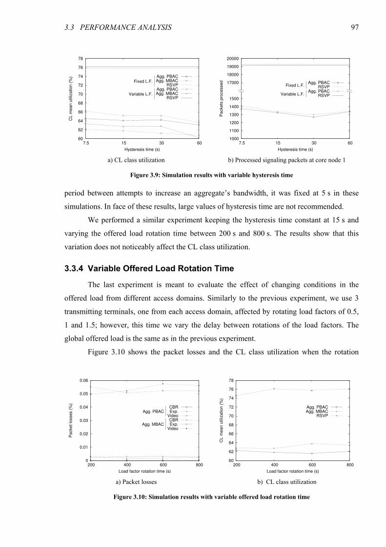
3.3 PERFORMANCE ANALYSIS 97
period between attempts to increase an aggregate’s bandwidth, it was fixed at 5 s in these
simulations. In face of these results, large values of hysteresis time are not recommended.
We performed a similar experiment keeping the hysteresis time constant at 15 s and
varying the offered load rotation time between 200 s and 800 s. The results show that this
variation does not noticeably affect the CL class utilization.
3.3.4 Variable Offered Load Rotation Time
The last experiment is meant to evaluate the effect of changing conditions in the
offered load from different access domains. Similarly to the previous experiment, we use 3
transmitting terminals, one from each access domain, affected by rotating load factors of 0.5,
1 and 1.5; however, this time we vary the delay between rotations of the load factors. The
global offered load is the same as in the previous experiment.
Figure 3.10 shows the packet losses and the CL class utilization when the rotation
60
62
64
66
68
70
72
74
76
78
7.5 15 30 60
CL
me
an
utiliz
atio
n (
%)
Hysteresis time (s)
Agg. PBACAgg. MBAC
RSVPAgg. PBACAgg. MBAC
RSVPVariable L.F.
Fixed L.F.
1000
1100
1200
1300
1400
1500
17000
18000
19000
20000
7.5 15 30 60
Pa
cke
ts p
roce
sse
d
Hysteresis time (s)
Agg. PBACRSVP
Agg. PBACRSVP
Fixed L.F.
Variable L.F.
a) CL class utilization b) Processed signaling packets at core node 1
Figure 3.9: Simulation results with variable hysteresis time
0
0.01
0.02
0.03
0.04
0.05
0.06
200 400 600 800
Pa
cke
t lo
sse
s (
%)
Load factor rotation time (s)
CBRExp.
VideoCBRExp.
VideoAgg. MBAC
Agg. PBAC
60
62
64
66
68
70
72
74
76
78
200 400 600 800
CL
me
an
utiliz
atio
n (
%)
Load factor rotation time (s)
Agg. PBACAgg. MBAC
RSVP
a) Packet losses b) CL class utilization
Figure 3.10: Simulation results with variable offered load rotation time
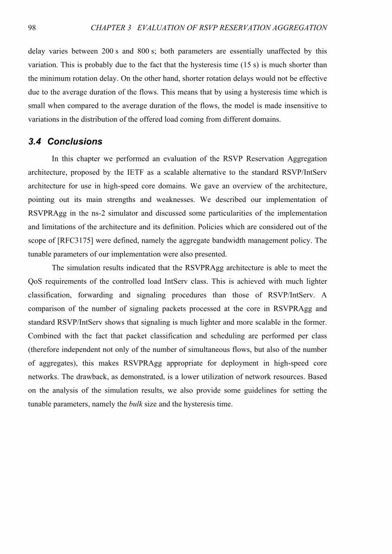
98 CHAPTER 3 EVALUATION OF RSVP RESERVATION AGGREGATION
delay varies between 200 s and 800 s; both parameters are essentially unaffected by this
variation. This is probably due to the fact that the hysteresis time (15 s) is much shorter than
the minimum rotation delay. On the other hand, shorter rotation delays would not be effective
due to the average duration of the flows. This means that by using a hysteresis time which is
small when compared to the average duration of the flows, the model is made insensitive to
variations in the distribution of the offered load coming from different domains.
3.4 Conclusions
In this chapter we performed an evaluation of the RSVP Reservation Aggregation
architecture, proposed by the IETF as a scalable alternative to the standard RSVP/IntServ
architecture for use in high-speed core domains. We gave an overview of the architecture,
pointing out its main strengths and weaknesses. We described our implementation of
RSVPRAgg in the ns-2 simulator and discussed some particularities of the implementation
and limitations of the architecture and its definition. Policies which are considered out of the
scope of [RFC3175] were defined, namely the aggregate bandwidth management policy. The
tunable parameters of our implementation were also presented.
The simulation results indicated that the RSVPRAgg architecture is able to meet the
QoS requirements of the controlled load IntServ class. This is achieved with much lighter
classification, forwarding and signaling procedures than those of RSVP/IntServ. A
comparison of the number of signaling packets processed at the core in RSVPRAgg and
standard RSVP/IntServ shows that signaling is much lighter and more scalable in the former.
Combined with the fact that packet classification and scheduling are performed per class
(therefore independent not only of the number of simultaneous flows, but also of the number
of aggregates), this makes RSVPRAgg appropriate for deployment in high-speed core
networks. The drawback, as demonstrated, is a lower utilization of network resources. Based
on the analysis of the simulation results, we also provide some guidelines for setting the
tunable parameters, namely the bulk size and the hysteresis time.
99
CHAPTER 4
SCALABLE RESERVATION-BASED QOS
We have seen in the previous chapter that while the RSVPRAgg model is a scalable
alternative to RSVP/IntServ, it suffers from network underutilization stemming from the
aggregation of state information and bulk updates to that information. If it were possible to
combine the scalability properties of the DiffServ model for packet classification, policing,
shaping and scheduling underneath RSVPRAgg, with a scalable model of per-flow
reservation signaling, we would be able to simultaneously benefit from the scalability
properties and avoid the underutilization limitation.
Despite the widespread belief that per-flow signaling and maintenance of state is not
scalable to high bandwidth core routers, no evidence has ever been produced that this
statement is universally true. This belief has its roots in the lack of scalability of the
RSVP/IntServ model, but does the same lack of scalability necessarily apply to any
conceivable application of per-flow state? We have strong reasons to believe it is possible to
develop a scalable per-flow signaling approach. Signaling traffic represents only a very small
fraction of the data traffic, and their proportion is similar at the access and the core. Storage of
per-flow information requires routers with sufficient memory, but this requirement is already
satisfied in today’s routers. Consider, for example, a router handling a maximum of a hundred
thousand simultaneous flows. If 100 bytes are required to store the state of each flow, the total
amount of memory necessary for storing per-flow information is 10 Mbytes, an amount that is
small by today’s standards, and expected to be even more so in the future due to “Moore’s
Law.” The Achilles’ heel of per-flow state maintenance is the burden of processing the
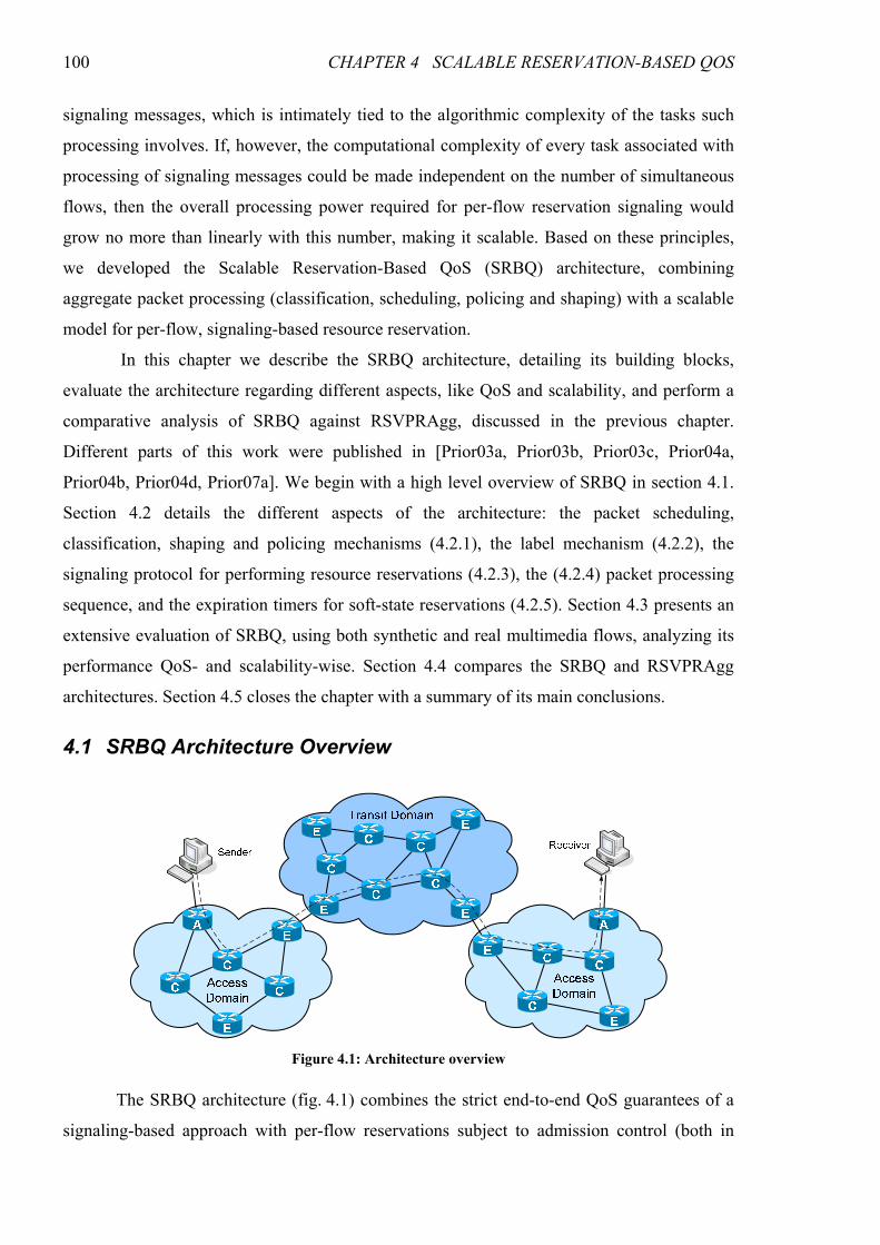
100 CHAPTER 4 SCALABLE RESERVATION-BASED QOS
signaling messages, which is intimately tied to the algorithmic complexity of the tasks such
processing involves. If, however, the computational complexity of every task associated with
processing of signaling messages could be made independent on the number of simultaneous
flows, then the overall processing power required for per-flow reservation signaling would
grow no more than linearly with this number, making it scalable. Based on these principles,
we developed the Scalable Reservation-Based QoS (SRBQ) architecture, combining
aggregate packet processing (classification, scheduling, policing and shaping) with a scalable
model for per-flow, signaling-based resource reservation.
In this chapter we describe the SRBQ architecture, detailing its building blocks,
evaluate the architecture regarding different aspects, like QoS and scalability, and perform a
comparative analysis of SRBQ against RSVPRAgg, discussed in the previous chapter.
Different parts of this work were published in [Prior03a, Prior03b, Prior03c, Prior04a,
Prior04b, Prior04d, Prior07a]. We begin with a high level overview of SRBQ in section 4.1.
Section 4.2 details the different aspects of the architecture: the packet scheduling,
classification, shaping and policing mechanisms (4.2.1), the label mechanism (4.2.2), the
signaling protocol for performing resource reservations (4.2.3), the (4.2.4) packet processing
sequence, and the expiration timers for soft-state reservations (4.2.5). Section 4.3 presents an
extensive evaluation of SRBQ, using both synthetic and real multimedia flows, analyzing its
performance QoS- and scalability-wise. Section 4.4 compares the SRBQ and RSVPRAgg
architectures. Section 4.5 closes the chapter with a summary of its main conclusions.
4.1 SRBQ Architecture Overview
The SRBQ architecture (fig. 4.1) combines the strict end-to-end QoS guarantees of a
signaling-based approach with per-flow reservations subject to admission control (both in
Figure 4.1: Architecture overview
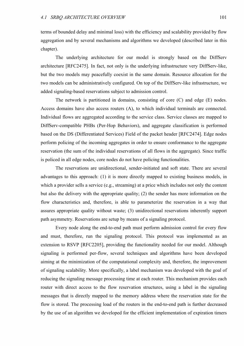
4.1 SRBQ ARCHITECTURE OVERVIEW 101
terms of bounded delay and minimal loss) with the efficiency and scalability provided by flow
aggregation and by several mechanisms and algorithms we developed (described later in this
chapter).
The underlying architecture for our model is strongly based on the DiffServ
architecture [RFC2475]. In fact, not only is the underlying infrastructure very DiffServ-like,
but the two models may peacefully coexist in the same domain. Resource allocation for the
two models can be administratively configured. On top of the DiffServ-like infrastructure, we
added signaling-based reservations subject to admission control.
The network is partitioned in domains, consisting of core (C) and edge (E) nodes.
Access domains have also access routers (A), to which individual terminals are connected.
Individual flows are aggregated according to the service class. Service classes are mapped to
DiffServ-compatible PHBs (Per-Hop Behaviors), and aggregate classification is performed
based on the DS (Differentiated Services) Field of the packet header [RFC2474]. Edge nodes
perform policing of the incoming aggregates in order to ensure conformance to the aggregate
reservation (the sum of the individual reservations of all flows in the aggregate). Since traffic
is policed in all edge nodes, core nodes do not have policing functionalities.
The reservations are unidirectional, sender-initiated and soft state. There are several
advantages to this approach: (1) it is more directly mapped to existing business models, in
which a provider sells a service (e.g., streaming) at a price which includes not only the content
but also the delivery with the appropriate quality; (2) the sender has more information on the
flow characteristics and, therefore, is able to parameterize the reservation in a way that
assures appropriate quality without waste; (3) unidirectional reservations inherently support
path asymmetry. Reservations are setup by means of a signaling protocol.
Every node along the end-to-end path must perform admission control for every flow
and must, therefore, run the signaling protocol. This protocol was implemented as an
extension to RSVP [RFC2205], providing the functionality needed for our model. Although
signaling is performed per-flow, several techniques and algorithms have been developed
aiming at the minimization of the computational complexity and, therefore, the improvement
of signaling scalability. More specifically, a label mechanism was developed with the goal of
reducing the signaling message processing time at each router. This mechanism provides each
router with direct access to the flow reservation structures, using a label in the signaling
messages that is directly mapped to the memory address where the reservation state for the
flow is stored. The processing load of the routers in the end-to-end path is further decreased
by the use of an algorithm we developed for the efficient implementation of expiration timers
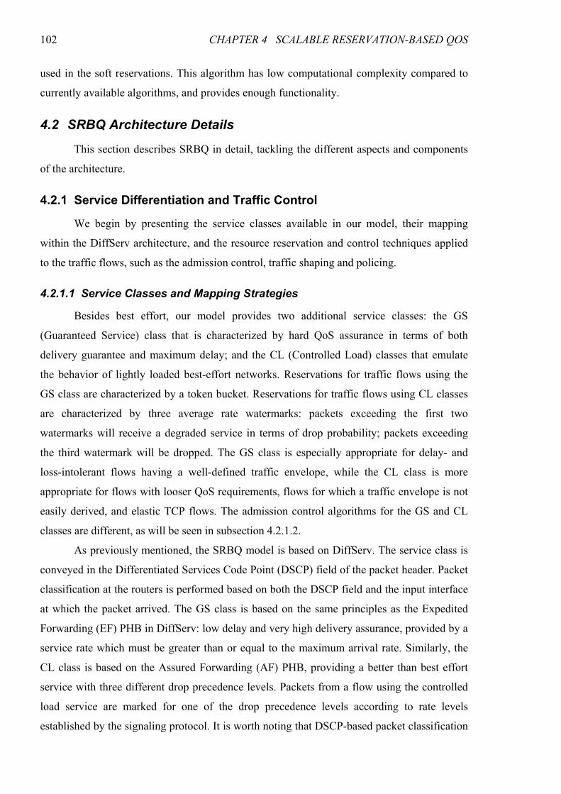
102 CHAPTER 4 SCALABLE RESERVATION-BASED QOS
used in the soft reservations. This algorithm has low computational complexity compared to
currently available algorithms, and provides enough functionality.
4.2 SRBQ Architecture Details
This section describes SRBQ in detail, tackling the different aspects and components
of the architecture.
4.2.1 Service Differentiation and Traffic Control
We begin by presenting the service classes available in our model, their mapping
within the DiffServ architecture, and the resource reservation and control techniques applied
to the traffic flows, such as the admission control, traffic shaping and policing.
4.2.1.1 Service Classes and Mapping Strategies
Besides best effort, our model provides two additional service classes: the GS
(Guaranteed Service) class that is characterized by hard QoS assurance in terms of both
delivery guarantee and maximum delay; and the CL (Controlled Load) classes that emulate
the behavior of lightly loaded best-effort networks. Reservations for traffic flows using the
GS class are characterized by a token bucket. Reservations for traffic flows using CL classes
are characterized by three average rate watermarks: packets exceeding the first two
watermarks will receive a degraded service in terms of drop probability; packets exceeding
the third watermark will be dropped. The GS class is especially appropriate for delay- and
loss-intolerant flows having a well-defined traffic envelope, while the CL class is more
appropriate for flows with looser QoS requirements, flows for which a traffic envelope is not
easily derived, and elastic TCP flows. The admission control algorithms for the GS and CL
classes are different, as will be seen in subsection 4.2.1.2.
As previously mentioned, the SRBQ model is based on DiffServ. The service class is
conveyed in the Differentiated Services Code Point (DSCP) field of the packet header. Packet
classification at the routers is performed based on both the DSCP field and the input interface
at which the packet arrived. The GS class is based on the same principles as the Expedited
Forwarding (EF) PHB in DiffServ: low delay and very high delivery assurance, provided by a
service rate which must be greater than or equal to the maximum arrival rate. Similarly, the
CL class is based on the Assured Forwarding (AF) PHB, providing a better than best effort
service with three different drop precedence levels. Packets from a flow using the controlled
load service are marked for one of the drop precedence levels according to rate levels
established by the signaling protocol. It is worth noting that DSCP-based packet classification
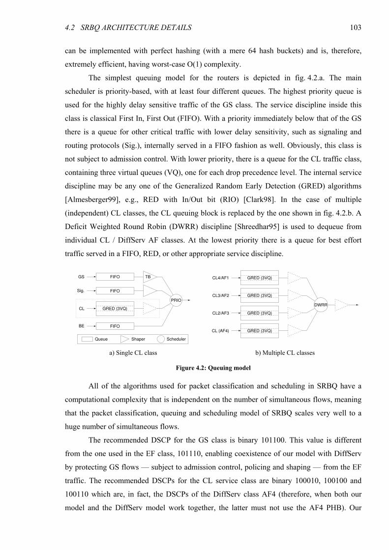
4.2 SRBQ ARCHITECTURE DETAILS 103
can be implemented with perfect hashing (with a mere 64 hash buckets) and is, therefore,
extremely efficient, having worst-case O(1) complexity.
The simplest queuing model for the routers is depicted in fig. 4.2.a. The main
scheduler is priority-based, with at least four different queues. The highest priority queue is
used for the highly delay sensitive traffic of the GS class. The service discipline inside this
class is classical First In, First Out (FIFO). With a priority immediately below that of the GS
there is a queue for other critical traffic with lower delay sensitivity, such as signaling and
routing protocols (Sig.), internally served in a FIFO fashion as well. Obviously, this class is
not subject to admission control. With lower priority, there is a queue for the CL traffic class,
containing three virtual queues (VQ), one for each drop precedence level. The internal service
discipline may be any one of the Generalized Random Early Detection (GRED) algorithms
[Almesberger99], e.g., RED with In/Out bit (RIO) [Clark98]. In the case of multiple
(independent) CL classes, the CL queuing block is replaced by the one shown in fig. 4.2.b. A
Deficit Weighted Round Robin (DWRR) discipline [Shreedhar95] is used to dequeue from
individual CL / DiffServ AF classes. At the lowest priority there is a queue for best effort
traffic served in a FIFO, RED, or other appropriate service discipline.
All of the algorithms used for packet classification and scheduling in SRBQ have a
computational complexity that is independent on the number of simultaneous flows, meaning
that the packet classification, queuing and scheduling model of SRBQ scales very well to a
huge number of simultaneous flows.
The recommended DSCP for the GS class is binary 101100. This value is different
from the one used in the EF class, 101110, enabling coexistence of our model with DiffServ
by protecting GS flows — subject to admission control, policing and shaping — from the EF
traffic. The recommended DSCPs for the CL service class are binary 100010, 100100 and
100110 which are, in fact, the DSCPs of the DiffServ class AF4 (therefore, when both our
model and the DiffServ model work together, the latter must not use the AF4 PHB). Our
FIFO
FIFO
FIFO
GRED (3VQ)
Queue Shaper Scheduler
GS TB
PRIO
CL
Sig.
BE
GRED (3VQ)
GRED (3VQ)
GRED (3VQ)
GRED (3VQ)
CL4/AF1
CL3/AF2
CL2/AF3
CL (AF4)
DWRR
a) Single CL class b) Multiple CL classes
Figure 4.2: Queuing model
104 CHAPTER 4 SCALABLE RESERVATION-BASED QOS
model may also contain different CL service classes using DSCPs from other AF classes,
provided these are not used by DiffServ.
4.2.1.2 Resource Reservation and Control
Admission control is performed at every node along the flow’s path. As we have
already mentioned, the admission control algorithms are different for the GS and the CL
Classes. In the GS class, parameter-based admission control must be performed in order to
strictly guarantee that enough bandwidth and buffer space are available at every router, even
in the worst case. QoS requirements are much looser in the CL class, allowing for the use of
measurement-based admission control in order to improve the utilization of network resources
(though parameter-based algorithms may likewise be used).
A GS flow i is characterized by a token bucket ( )ii br , . In order to perform admission
control for a new GS flow, the router computes (incrementally) the summed token bucket for
all admitted flows sharing the same service class and output interface, using the formulas
∑=i isum rR and ∑=
i isum bB , where ir and ib are, respectively, the token bucket rate and
depth of the individual flows. A new flow j is accepted iff maxGSjsum RrR ≤+ and
maxGSjsum BbB ≤+ , where maxGSR and maxGSB are the configured limits of GS rate and bucket
depth for the output interface.
CL flows are characterized by three average rate watermarks, two for degrading
service and a third one for packet dropping. The three watermarks wsumR , that characterize the
aggregate are obtained by summing the corresponding watermarks wir , from the individual
flows, ∑=i wiwsum rR ,, , and a new flow j is admitted iff wRrR wCLwjwsum ∀≤+ ,max,,, , where
wCLR max, is the configured maximum rate for the wth CL watermark for the output interface.
Since some amount of packet loss is tolerated, admission control is not as critical as in the
case of GS. This allows us to somewhat improve network resource utilization, either by using
Measurement-Based Admission Control (MBAC) algorithms, replacing wsumR , with an
estimate, or by using Parameter-Based Admission Control (PBAC) with overbooking,
multiplying the configured maximum rates by an overbooking factorβ . Please refer to
Appendix A for more information on PBAC and MBAC algorithms.
4.2 SRBQ ARCHITECTURE DETAILS 105
4.2.1.2.1 Traffic Shaping
As can be seen in fig. 4.2.a, the highest priority queues, corresponding to the GS
traffic class and signaling/routing traffic, must be subject to a traffic shaper. The traffic shaper
for the GS class is of token bucket type, and is parameterized using the summed values sumR
and sumB . This shaper is necessary in order to avoid packet discarding by the policer at the
input interface of the following node (or, more precisely, at the following edge node, since no
policing is performed at the core), and also helps in reducing multiplexing jitter. Since the
traffic is shaped to the summed token bucket of the class, which is an upper bound to the
actual traffic in the aggregate, this shaper does not degrade the quality of service guarantees
of the GS flows because “greedy shapers come for free” [Boudec01].
A different kind of shaper is also used in our model. Not all terminal nodes are able to
perform precise token bucket scheduling for GS flows, and even if they do, jitter is inevitably
introduced by multiplexing several GS flows, or a GS flow and traffic from other classes.
Since this jitter could lead to packets being dropped by the policing module at the access
router even for applications generating conformant traffic, GS flows are ingress-shaped,
instead of policed, at the access router. This shaping is performed on a per-flow basis. Since
all GS flows are shaped into conformance, the GS aggregate is also guaranteed to be
conformant to the aggregate reservation.
The signaling/routing traffic, though not subject to admission control, must also be
shaped in order to prevent starvation of the bandwidth assigned to the CL class. Since this
traffic will not be subject to policing at the input interface of the following node, the shaper
may be simplified to a work-conserving rate limiter (i.e., rate is only limited when lower
priority classes have queued packets waiting for transmission).
The CL class may also be shaped; however this is only needed if the network
administrator wants to make sure that some amount of bandwidth always remains for best
effort traffic. Since traffic from the CL class tolerates some amount of packet dropping, the
shaper may be a simple work-conserving rate limiter.
4.2.1.2.2 Traffic Policing
There are four different types of nodes in our model: end nodes, access routers (A),
edge routers (E) and core routers (C). All of them perform signaling and support the queuing
model described above, in subsection 4.2.1.1. The access nodes perform per-flow policing,
ensuring that traffic from each individual flow does not exceed its reservation parameters. As
previously stated, GS flows are shaped at these nodes, instead of policed. Edge nodes perform
106 CHAPTER 4 SCALABLE RESERVATION-BASED QOS
aggregate policing only, with an aggregate consisting on a DSCP value (or a set of DSCP
values corresponding to a PHB group) per input interface. There is no need for edge routers to
perform per-flow policing, since this has already been done at the access routers. Edge nodes
may also perform re-marking to a higher drop probability within the CL class. Since the re-
marking is to be performed at aggregate level, it must be color-aware1 in order to avoid unfair
service degradation to “well behaved” flows. Core routers perform no policing, as they
assume that all traffic has already been policed in their domain, either by an edge router (for
traffic coming from different domains) or by an access router (for eventual traffic generated
inside their own domain) and is, therefore, conformant to the reservations.
Contrary to traffic shaping (performed at the output interface) which is always
performed on traffic class aggregates, policing (at the input interface) is performed in a per-
flow basis at the access routers. This is required for ensuring that flows are conformant to the
reservations, and also to perform drop precedence (re-)marking for CL flows. Forcing every
flow to conform to its reservation ensures that no service degradation is inflicted by a greedy
flow on the remaining flows sharing the same service class and output interface.
In order to avoid packet dropping in the GS class even in presence of some clock drift
between routers (or timer imprecision at the previous router), the bucket of the aggregate GS
policer may be increased by a small amount (e.g., an MTU).
4.2.2 Label Mechanism
Usually, the scalability limitation is imposed neither by the signaling traffic nor by the
maintenance of the flow information — signaling traffic represents only a very small fraction
of the data traffic, and the amount of memory required for storage of per-flow information is
available on today’s routers. The scalability limitation stems from the computational
complexity of the algorithms used in processing the signaling messages.
One potentially scalability-limiting task for the core routers, particularly in terms of
worst case, is the lookup of the stored flow information, based on the 5-tuple parameters that
specify the flow. Usually, this lookup is implemented using hash tables, but perfect hashing
for the 5-tuple is infeasible. In order to efficiently access the reservation structures we
developed a label mechanism which allows direct access to these structures without any need
for hash lookups. These labels are 32-bit values whose meaning is externally opaque, but
1 Color-aware re-marking means that a packet may be demoted to a higher drop probability, but not promoted to a lower one
(the re-marker is aware of the packet’s previous “color”).
4.2 SRBQ ARCHITECTURE DETAILS 107
internally are the memory address of the reservation structure (most routers will use 32-bit
processors; in routers with more than 32-bits of addressing space, the label may be an offset).
Once a signaling message is received, its LABEL object will be used to directly access
the reservation flow state. This procedure significantly reduces the message processing time at
the router and the signaling complexity. As will be shown, only the initial messages sent to
perform resource reservation are excluded from this efficient access, but since the reservation
does not yet exist, they would not need it anyway. Allocating a new structure is trivial,
consisting in taking the first element from a linked list. The installation of the labels in the
flow reservation structures will be detailed in subsection 4.2.3.2.
The label mechanism is also significantly advantageous for all per-flow processing.
For example, per-flow policing performed at the access routers needs to access the flow state
each time a packet is received. Although the number of flows at the access network is much
smaller than that of core networks, the use of a mechanism that provides direct access to the
flow information allows for a significant reduction in its processing load. Finally, the route
change detection (in case of rerouting) can also make use of the labels. More specifically, the
router compares the next hop address obtained from the routing table with the next hop
address stored in the reservation structure of the flow. A mismatch between these values
indicates that the route has changed, and the router will react accordingly.
In order to benefit from these advantages on per-flow processing and fast and efficient
route change detection, however, data packets need to carry the label information in the
header. Notice that in the GS class it is strictly required that no packet is admitted at a router
unless there is a valid reservation in place for the corresponding flow. CL classes are more
tolerant to packet losses, and therefore, do not require the label in the packet header.
Whenever a GS packet arrives at a node, it is necessary to check the reservation
structure before accepting it. Checking the reservation implies the existence of the label
information in the GS packet headers in order to be performed in an efficient way. In IPv4 we
could use the Identification and Fragment Offset fields of the packet header for this purpose,
since these fields are only used when fragmentation occurs (although it was mentioned in
[Stoica00] that only 0.13% of the packets in the Internet are fragmented). Since it is possible
to avoid fragmentation by setting the Don’t Fragment flag, these fields can be used without
affecting the system operation. The GS service class excludes fragmentation anyway, since
the additional headers would increase the effective rate of the flow, eventually leading to
packet losses (the RSVP/IntServ Controlled Load and Guaranteed services also preclude
fragmentation due to the inaccessibility of port information to build the 5-tuple flow identifier
108 CHAPTER 4 SCALABLE RESERVATION-BASED QOS
[RFC2211, RFC2212]). Since the sum of the available bits is only 29 (less than the 32 bits
required for the Label object), the three last bits of the labels must be zero, implying that all
memory structure addresses are aligned to 8-byte (i.e., 64-bit) boundaries. As an alternative,
the label could be conveyed by means of an IPv4 header option, though this would increase
the overhead.
In IPv6 we could only make use of the Flow Label header field to carry the labels.
However, the length of this field is just 20 bits, which is not enough to carry a memory
address. In order to avoid the overhead of using an IPv6 extension header to convey the 32-bit
label, an alternative labeling scheme is used — in this case, the label is used as an index to a
table of reservations. Access to the reservation structure is still O(1), as its memory address is
given by the simple formula ResvAddr = TableAddr + Index × StructSize. This use of the
Flow Label field, however, is not compliant to [RFC3697], which states that a Flow Label
value is valid only within the context of the 3-tuple (Source Address, Destination Address,
Flow Label) and that it must be delivered unchanged to the destination node.
It is worth noting that, in spite of all the advantages, the labels are not used for packet
classification (except perhaps at the access routers), since it is performed on an aggregate
basis, using just the DS field of the IP header.
4.2.3 Signaling Protocol
As we have already mentioned, SRBQ signaling works on a hop-by-hop basis,
providing unidirectional, soft state, sender-initiated reservations. Instead of creating a whole
new protocol from the ground up, we have chosen to implement it as an extension to the
RSVP protocol for several reasons: (1) RSVP is a widely known and supported protocol; (2)
it also works on a hop-by-hop basis; (3) it also uses routes established by an underlying
routing protocol; and (4) RSVP already implements some of the required functionality for our
model. Although our signaling protocol is an extension of RSVP, it is much more scalable,
since (1) the access to the flow information is simple with O(1) complexity, (2) expiration
timers for the soft reservations are implemented in a very effective, low complexity way, and
(3) it uses simple identification of the reservations in order to decrease the length of the
refresh and explicit tear down messages. These topics will be described in more detail in the
following subsections.
4.2.3.1 Signaling Messages
Since RSVP is meant to perform receiver-initiated reservations, we had to extend it by
adding three new message types: SResv (Sender Reservation), SResvStat (Sender Reservation
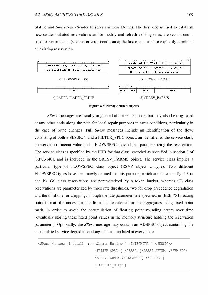
4.2 SRBQ ARCHITECTURE DETAILS 109
Status) and SResvTear (Sender Reservation Tear Down). The first one is used to establish
new sender-initiated reservations and to modify and refresh existing ones; the second one is
used to report status (success or error conditions); the last one is used to explicitly terminate
an existing reservation.
SResv messages are usually originated at the sender node, but may also be originated
at any other node along the path for local repair purposes in error conditions, particularly in
the case of route changes. Full SResv messages include an identification of the flow,
consisting of both a SESSION and a FILTER_SPEC object, an identifier of the service class,
a reservation timeout value and a FLOWSPEC class object parameterizing the reservation.
The service class is specified by the PHB for that class, encoded as specified in section 2 of
[RFC3140], and is included in the SRESV_PARMS object. The service class implies a
particular type of FLOWSPEC class object (RSVP object C-Type). Two different
FLOWSPEC types have been newly defined for this purpose, which are shown in fig. 4.3 (a
and b). GS class reservations are parameterized by a token bucket, whereas CL class
reservations are parameterized by three rate thresholds, two for drop precedence degradation
and the third one for dropping. Though the rate parameters are specified in IEEE-754 floating
point format, the nodes must perform all the calculations for aggregates using fixed point
math, in order to avoid the accumulation of floating point rounding errors over time
(eventually storing these fixed point values in the memory structure holding the reservation
parameters). Optionally, the SResv message may contain an ADSPEC object containing the
accumulated service degradation along the path, updated at every node.
<SResv Message (initial)> ::= <Common Header> [ <INTEGRITY> ] <SESSION>
<FILTER_SPEC> [ <LABEL> ]<LABEL_SETUP> <RSVP_HOP>
<SRESV_PARMS> <FLOWSPEC> [ <ADSPEC> ]
[ <POLICY_DATA> ]
a) FLOWSPEC (GS) b) FLOWSPEC (CL)
c) LABEL / LABEL_SETUP d) SRESV_PARMS
Figure 4.3: Newly defined objects
110 CHAPTER 4 SCALABLE RESERVATION-BASED QOS
The LABEL_SETUP and LABEL objects, whose format is shown in fig. 4.3.c,
include a 32-bit value, the label, which is directly mapped to the memory address containing
the flow reservation information. These objects will be used, respectively, to install the label
at reservation setup time and to access the memory address when further messages are
processed. The process of label installation is detailed in subsection 4.2.3.2.
The SRESV_PARMS object is shown in fig. 4.3.d. In addition to the PHB specifying
the service class, it includes a 3-bit value (Rex) that represents the reservation expiration time.
This value is in a 2-logarithmic scale and will be used with the developed algorithm to
efficiently implement expiration timers. This algorithm will be detailed in subsection 4.2.5. It
also includes a message identification number (MsgID) which allows for an association
between the SResv message and an eventual SResvStat message in response to a SResv
message.
SResv messages used for refreshing reservations without changing parameters (with
the possible exception of reservation expiration timeout) are simpler than the full SResv
messages used for the initial reservation setup. The SESSION and FILTER_SPEC objects are
absent, as is the FLOWSPEC class object. The LABEL_SETUP object is also absent from
refresh-only SResv messages.
<SResv Message (refresh)> ::= <Common Header> [ <INTEGRITY> ] <LABEL> <RSVP_HOP>
<SRESV_PARMS> [ <POLICY_DATA> ]
SResv messages may include a POLICY_DATA object that contains policy
information applicable to the requested reservation. This feature may be used by the service
providers to account and charge for an increased service quality and/or to enforce an
acceptance policy for reservations. A POLICY_DATA object may be added to an SResv
message, when entering the domain, by the ingress router. The information therein contained
may be retrieved from an AAAC (Authentication, Authorization, Accounting and Charging)
server. The policy information is used by routers inside the domain, which will perform
admission control decisions based not only in available network resources, but also on the
acceptance policy; it is removed at the egress router. The definition of the POLICY_DATA
object format and processing may be domain-specific, and is out of the scope of this work.
Basic security in signaling is achieved by means of INTEGRITY objects, as in the standard
RSVP protocol.
SResvStat messages are used for both reservation confirmation and error reporting.
The first kind is generated at the receiver node, triggered by the reception of an SResv
4.2 SRBQ ARCHITECTURE DETAILS 111
message, and is propagated up to the sender. The second kind may be generated by any other
node for reporting an error condition to the previous node which, depending on the error type,
may be propagated up to the sender, or trigger a local repair procedure. The ERROR_SPEC
object is used to report a successful reservation or to describe an error condition. SResvStat
messages sent in response to an SResv message also include a copy of the SRESV_PARMS
object from that SResv message.
<SResvStat> ::= <Common Header> [ <INTEGRITY> ] <LABEL> [ <LABEL_SETUP> ]
<RSVP_HOP> [ <SRESV_PARMS> ] [ <ADSPEC> ] <ERROR_SPEC>
SResvTear messages are generated either by the sender node to explicitly terminate a
reservation, or by any other node along the path which detects a route change, in order to
remove the stale reservation from the old path. Among other objects, they include the LABEL
object, so the nodes can directly access to the flow information in order to remove the
reservation.
<SResvTear Message> ::= <Common Header> [ <INTEGRITY> ] <LABEL> <RSVP_HOP>
If there is no explicit teardown and no refresh messages, the timer associated to the
specific flow expires. The flow reservation is then terminated, and the corresponding
information is removed from the reservation table.
Since in SRBQ signaling must be performed at every node (including core routers),
much care has been taken in reducing the processing load imposed by the signaling protocol,
making use of computationally efficient algorithms and techniques only. The next subsections
will address the details of the signaling protocol that increase its scalability.
4.2.3.2 Signaling Dynamics
As we have already mentioned, although the base signaling protocol is RSVP, the
proposed protocol is sender-initiated. This characteristic introduces a large difference between
the proposed protocol and standard RSVP. Being sender-initiated means that upon receiving
the first message (SResv), the nodes along the path run the admission control algorithm (based
on the token bucket parameters or on network measurements), and perform resource
reservation for the new flow. Notice that, in this model, performing resource reservation for a
new flow is equivalent to increasing the bandwidth allocation for the class to which the new
flow belongs, since our model is based on DiffServ.
112 CHAPTER 4 SCALABLE RESERVATION-BASED QOS
When a router receives an initial SResv message requesting a new reservation and the
request is accepted, the SResv message is forwarded to the following router and the updated
traffic specification for the class is committed to the admission control module. This traffic
specification, though, is not committed to the policing and queuing modules until the
corresponding SResvStat, confirming a successful reservation up to the receiver, arrives. This
ensures that whenever a router updates its resource allocation for a class, all routers towards
the receiver terminal already have performed their updates. Otherwise, packet dropping could
be inflicted on the class by the policing module of the following node in the time interval
between resource allocation updates of the two routers. The SResvStat message will not only
inform the sender about the success or failure of the admission request, but will also trigger
the commitment of the resource reservation to both the policing and the queuing modules at
the routers if the reservation succeeded, or remove it from the admission control module if it
failed.
Each reservation structure stores, among other parameters, the flow specification and
three label fields: B, T and F. These label fields are, respectively, the label to be used in
signaling messages (or data packets) sent backwards (towards the sender), the label for the
router itself (which may be implicit), and the label to be used in messages sent forwards
(towards the receiver). The obvious exceptions are the end nodes: the sender has no B label
and the receiver has no F label. Upon receiving a refresh SResv message, a node checks the
label field in the message, directly accesses the state information of the flow, updates its
expiration timer, and copies the F label field stored in the reservation structure to the label
field of the SResv message to be forwarded. This label will be used by the next node to
directly access the reservation state of the flow.
Labels are installed at reservation setup time, as shown in fig. 4.4, using
LABEL_SETUP objects in the SResv and SResvStat messages.
The SRBQ signaling protocol works as follows (fig. 4.4). The initial SResv message,
originated at the sender (1), contains, among other objects, the flow reservation specification
and the label TS. This label, conveyed by the LABEL_SETUP object, will be used in
messages sent by the R1 router to the sender. R1 performs admission control, based on the
flow reservation parameters. If the flow can be accepted, the router updates the resource
reservation of the flow’s class2, allocates a reservation structure for the flow, stores the label
at the B field for this reservation, and forwards the SResv message to R2 (2) after changing the
LABEL_SETUP to T1. If the flow cannot be accepted, a SResvStat message is sent towards 2 As has been previously stated, this reservation is only committed to the admission control module at this point.
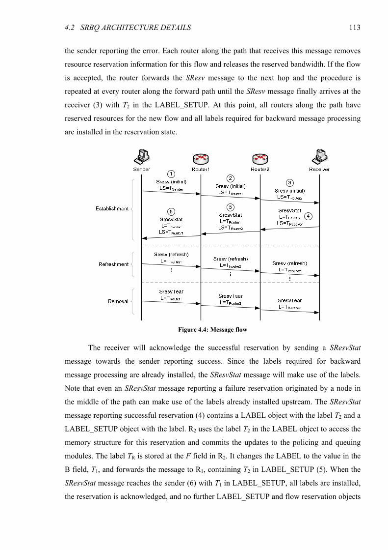
4.2 SRBQ ARCHITECTURE DETAILS 113
the sender reporting the error. Each router along the path that receives this message removes
resource reservation information for this flow and releases the reserved bandwidth. If the flow
is accepted, the router forwards the SResv message to the next hop and the procedure is
repeated at every router along the forward path until the SResv message finally arrives at the
receiver (3) with T2 in the LABEL_SETUP. At this point, all routers along the path have
reserved resources for the new flow and all labels required for backward message processing
are installed in the reservation state.
The receiver will acknowledge the successful reservation by sending a SResvStat
message towards the sender reporting success. Since the labels required for backward
message processing are already installed, the SResvStat message will make use of the labels.
Note that even an SResvStat message reporting a failure reservation originated by a node in
the middle of the path can make use of the labels already installed upstream. The SResvStat
message reporting successful reservation (4) contains a LABEL object with the label T2 and a
LABEL_SETUP object with the label. R2 uses the label T2 in the LABEL object to access the
memory structure for this reservation and commits the updates to the policing and queuing
modules. The label TR is stored at the F field in R2. It changes the LABEL to the value in the
B field, T1, and forwards the message to R1, containing T2 in LABEL_SETUP (5). When the
SResvStat message reaches the sender (6) with T1 in LABEL_SETUP, all labels are installed,
the reservation is acknowledged, and no further LABEL_SETUP and flow reservation objects
Figure 4.4: Message flow
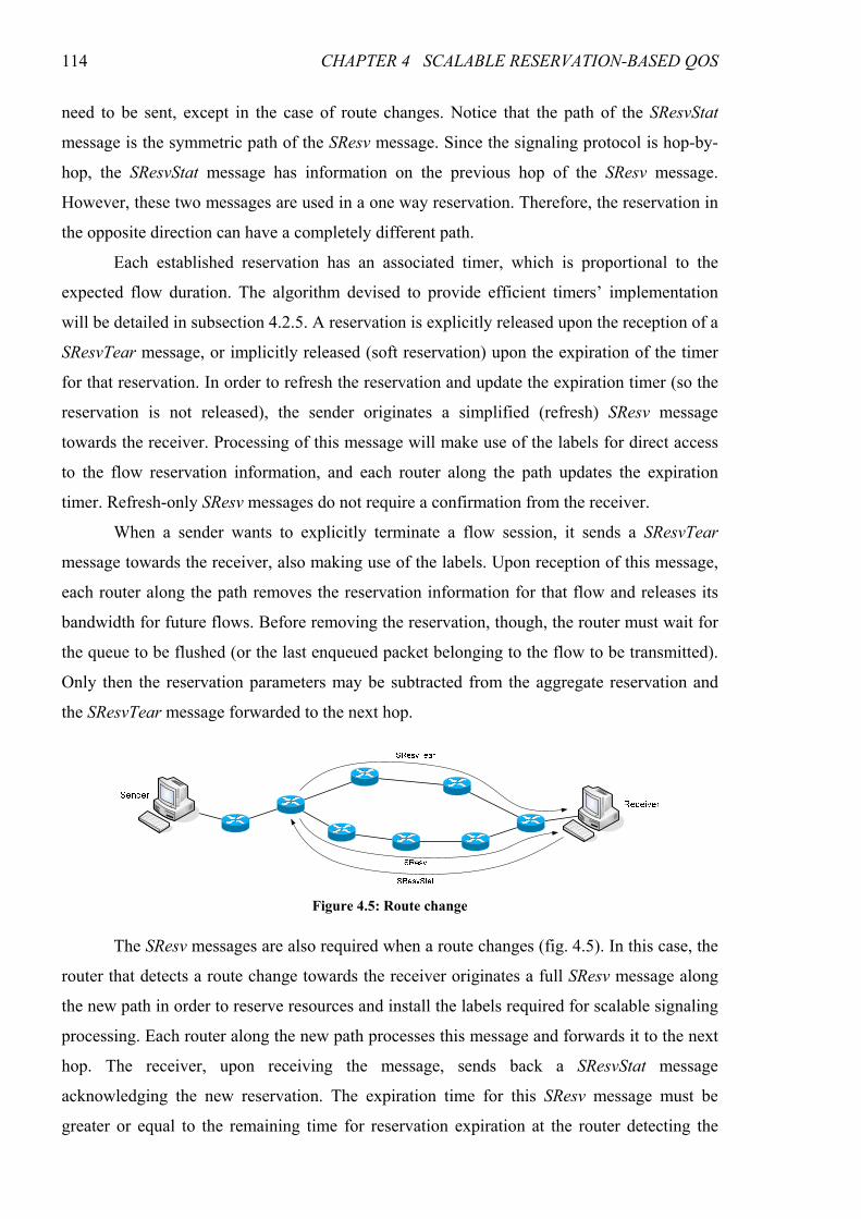
114 CHAPTER 4 SCALABLE RESERVATION-BASED QOS
need to be sent, except in the case of route changes. Notice that the path of the SResvStat
message is the symmetric path of the SResv message. Since the signaling protocol is hop-by-
hop, the SResvStat message has information on the previous hop of the SResv message.
However, these two messages are used in a one way reservation. Therefore, the reservation in
the opposite direction can have a completely different path.
Each established reservation has an associated timer, which is proportional to the
expected flow duration. The algorithm devised to provide efficient timers’ implementation
will be detailed in subsection 4.2.5. A reservation is explicitly released upon the reception of a
SResvTear message, or implicitly released (soft reservation) upon the expiration of the timer
for that reservation. In order to refresh the reservation and update the expiration timer (so the
reservation is not released), the sender originates a simplified (refresh) SResv message
towards the receiver. Processing of this message will make use of the labels for direct access
to the flow reservation information, and each router along the path updates the expiration
timer. Refresh-only SResv messages do not require a confirmation from the receiver.
When a sender wants to explicitly terminate a flow session, it sends a SResvTear
message towards the receiver, also making use of the labels. Upon reception of this message,
each router along the path removes the reservation information for that flow and releases its
bandwidth for future flows. Before removing the reservation, though, the router must wait for
the queue to be flushed (or the last enqueued packet belonging to the flow to be transmitted).
Only then the reservation parameters may be subtracted from the aggregate reservation and
the SResvTear message forwarded to the next hop.
The SResv messages are also required when a route changes (fig. 4.5). In this case, the
router that detects a route change towards the receiver originates a full SResv message along
the new path in order to reserve resources and install the labels required for scalable signaling
processing. Each router along the new path processes this message and forwards it to the next
hop. The receiver, upon receiving the message, sends back a SResvStat message
acknowledging the new reservation. The expiration time for this SResv message must be
greater or equal to the remaining time for reservation expiration at the router detecting the
Figure 4.5: Route change
4.2 SRBQ ARCHITECTURE DETAILS 115
route change. A SResvTear message should also be sent, when possible, to the old next hop in
order to remove the stale reservation from the old path.
If a timer expires for lack of refreshment, the reservation parameters are immediately
removed from the policing module. However, only after the queue of the traffic class to which
the flow belongs has been flushed, or the last enqueued packet from that flow has been
transmitted, the reservation may be removed from the admission control and traffic control
modules. This ensures that, under every circumstance, there is enough bandwidth allocated to
the class to send those packets without negatively affecting other flows in the same class.
4.2.4 Packet Processing
Whenever a data packet arrives at a router, it must be processed according to specific
rules which, due to different requirements, are different for the GS and CL classes. In
particular, no GS packet may be admitted if there is not an up-to-date reservation in place,
like in the case of expiration of the reservation or an occurrence of a route change.
The first action performed by the router when a data packet arrives is to look at the
DSCP and find out if the packet belongs to a service class with reservations. If the packet
belongs to the GS class, the following sequence of actions is then performed:
1. Get the label from the packet header;
2. Check out if there is a valid reservation in place corresponding to the label; if not, the
packet is dropped (or re-marked to best-effort);
3. If there is a valid reservation, the packet is passed to the policing module (except at the
core routers);
4. The next hop given by the routing table is then compared to the one stored in the
reservation structure; if they are different, the route has changed — the packet is dropped
(or re-marked to best-effort) and a procedure to reestablish the reservation through the
new route (and, if possible, to remove the stale reservation from the old route) is triggered;
5. If there is a valid reservation in place, the policing module accepts the packet and no route
change has occurred, the packet is finally enqueued in the GS queue of the output
interface.
If, on the other hand, the packet belongs to (one of) the CL class(es), the sequence is
simpler. Since these flows are tolerant to small amounts of packet loss and flow interference,
immediate route change detection and reservation checking for every packet are not required.
This means that it is possible to drop the requirement for the data packets to carry the label
and the prohibition of datagram fragmentation. In this case, a route change could go
116 CHAPTER 4 SCALABLE RESERVATION-BASED QOS
undetected until the next SResv (refresh) arrives. CL packets, then, are immediately passed to
the policer (if applicable) and then enqueued at the output interface given by the routing table.
Best-effort and signaling packets are processed as usual.
4.2.5 Soft Reservations and Efficient Timer Implementation
In SRBQ, reservations are soft state: if no SResvTear message is received and the
reservation is not refreshed, the associated timer expires and it is removed. Soft state
reservations have the obvious advantage of providing adaptability to changing network
conditions; however, they require the implementation of expiration timers. The basic
implementation concept for timers is a sorted event queue: the processor waits until the first
timer value in the list expires, dequeues it, performs the appropriate processing, and then goes
on waiting for the next timer value to expire. While dequeuing an event is trivial, inserting an
event with a random expiration time is an expensive operation, highly dependent on the total
number of events queued. Some algorithms have been proposed [Varghese97, Aron00] for the
efficient implementation of timers, but while general enough for implementing any kind of
timer, these algorithms are still overly complex for our purpose. Contrasting to the complexity
of generic timers, fixed delay timers are very simple and efficient to implement: in this case,
the event queue is treated in FIFO fashion, providing both trivial event queuing and
dequeuing. Fixed delay termination timers, however, are undesirable in the case of
reservations which may have very dissimilar life spans.
Trying to achieve a balance between the simplicity of fixed delay timers and the
flexibility of generic timers, we have created an algorithm which has trivial timer queuing and
a low and constant cost timer dequeuing, providing eight possible timer delays in a base-2
logarithmic scale. These values map to a timer delay range of 1:128, which is enough for our
purposes. The implementation is based on eight different queues, each of which has an
associated fixed delay. Internally, therefore, these queues are served using a FIFO discipline.
Flow timeouts are chosen from one of the eight possible values using a three bit field in a
SRESV_PARMS object included in SResv messages. Queuing an event is a simple matter of
adding it to the tail of the corresponding queue, which is trivial. Dequeuing an event means
choosing one of the eight possible queues (the one whose timers expires first) and taking the
first event from that queue. Anyway, timers should not expire very frequently, as most of the
time reservations will either be refreshed or explicitly terminated by means of a SResvTear
message, accessing the timer using a reference stored in the flow structure.
Having a good range of reservation expiration timer values means that short-lived
flows will not remain stale for long times whenever something unusual occurs (such as an
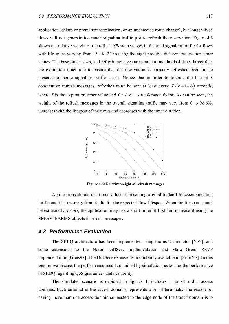
4.3 PERFORMANCE EVALUATION 117
application lockup or premature termination, or an undetected route change), but longer-lived
flows will not generate too much signaling traffic just to refresh the reservation. Figure 4.6
shows the relative weight of the refresh SResv messages in the total signaling traffic for flows
with life spans varying from 15 s to 240 s using the eight possible different reservation timer
values. The base timer is 4 s, and refresh messages are sent at a rate that is 4 times larger than
the expiration timer rate to ensure that the reservation is correctly refreshed even in the
presence of some signaling traffic losses. Notice that in order to tolerate the loss of k
consecutive refresh messages, refreshes must be sent at least every ( )∆++1/ kT seconds,
where T is the expiration timer value and 10 <∆< is a tolerance factor. As can be seen, the
weight of the refresh messages in the overall signaling traffic may vary from 0 to 98.6%,
increases with the lifespan of the flows and decreases with the timer duration.
Applications should use timer values representing a good tradeoff between signaling
traffic and fast recovery from faults for the expected flow lifespan. When the lifespan cannot
be estimated a priori, the application may use a short timer at first and increase it using the
SRESV_PARMS objects in refresh messages.
4.3 Performance Evaluation
The SRBQ architecture has been implemented using the ns-2 simulator [NS2], and
some extensions to the Nortel DiffServ implementation and Marc Greis’ RSVP
implementation [Greis98]. The DiffServ extensions are publicly available in [PriorNS]. In this
section we discuss the performance results obtained by simulation, assessing the performance
of SRBQ regarding QoS guarantees and scalability.
The simulated scenario is depicted in fig. 4.7. It includes 1 transit and 5 access
domains. Each terminal in the access domains represents a set of terminals. The reason for
having more than one access domain connected to the edge node of the transit domain is to
0
20
40
60
80
100
4 8 16 32 64 128 256 512
Re
fre
sh
we
igh
t (%
)
Expiration timer (s)
15 s30 s60 s
120 s240 s
Figure 4.6: Relative weight of refresh messages
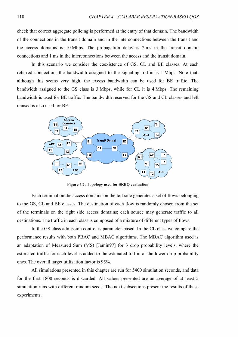
118 CHAPTER 4 SCALABLE RESERVATION-BASED QOS
check that correct aggregate policing is performed at the entry of that domain. The bandwidth
of the connections in the transit domain and in the interconnections between the transit and
the access domains is 10 Mbps. The propagation delay is 2 ms in the transit domain
connections and 1 ms in the interconnections between the access and the transit domain.
In this scenario we consider the coexistence of GS, CL and BE classes. At each
referred connection, the bandwidth assigned to the signaling traffic is 1 Mbps. Note that,
although this seems very high, the excess bandwidth can be used for BE traffic. The
bandwidth assigned to the GS class is 3 Mbps, while for CL it is 4 Mbps. The remaining
bandwidth is used for BE traffic. The bandwidth reserved for the GS and CL classes and left
unused is also used for BE.
Each terminal on the access domains on the left side generates a set of flows belonging
to the GS, CL and BE classes. The destination of each flow is randomly chosen from the set
of the terminals on the right side access domains; each source may generate traffic to all
destinations. The traffic in each class is composed of a mixture of different types of flows.
In the GS class admission control is parameter-based. In the CL class we compare the
performance results with both PBAC and MBAC algorithms. The MBAC algorithm used is
an adaptation of Measured Sum (MS) [Jamin97] for 3 drop probability levels, where the
estimated traffic for each level is added to the estimated traffic of the lower drop probability
ones. The overall target utilization factor is 95%.
All simulations presented in this chapter are run for 5400 simulation seconds, and data
for the first 1800 seconds is discarded. All values presented are an average of at least 5
simulation runs with different random seeds. The next subsections present the results of these
experiments.
Figure 4.7: Topology used for SRBQ evaluation
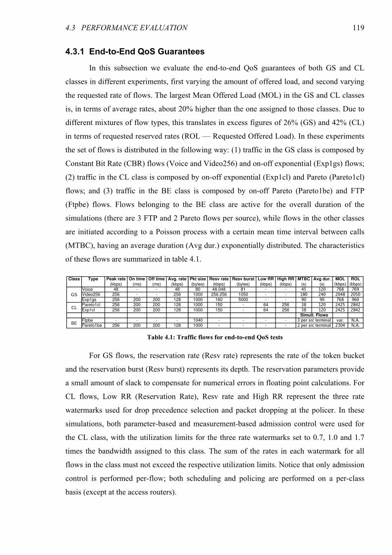
4.3 PERFORMANCE EVALUATION 119
4.3.1 End-to-End QoS Guarantees
In this subsection we evaluate the end-to-end QoS guarantees of both GS and CL
classes in different experiments, first varying the amount of offered load, and second varying
the requested rate of flows. The largest Mean Offered Load (MOL) in the GS and CL classes
is, in terms of average rates, about 20% higher than the one assigned to those classes. Due to
different mixtures of flow types, this translates in excess figures of 26% (GS) and 42% (CL)
in terms of requested reserved rates (ROL — Requested Offered Load). In these experiments
the set of flows is distributed in the following way: (1) traffic in the GS class is composed by
Constant Bit Rate (CBR) flows (Voice and Video256) and on-off exponential (Exp1gs) flows;
(2) traffic in the CL class is composed by on-off exponential (Exp1cl) and Pareto (Pareto1cl)
flows; and (3) traffic in the BE class is composed by on-off Pareto (Pareto1be) and FTP
(Ftpbe) flows. Flows belonging to the BE class are active for the overall duration of the
simulations (there are 3 FTP and 2 Pareto flows per source), while flows in the other classes
are initiated according to a Poisson process with a certain mean time interval between calls
(MTBC), having an average duration (Avg dur.) exponentially distributed. The characteristics
of these flows are summarized in table 4.1.
For GS flows, the reservation rate (Resv rate) represents the rate of the token bucket
and the reservation burst (Resv burst) represents its depth. The reservation parameters provide
a small amount of slack to compensate for numerical errors in floating point calculations. For
CL flows, Low RR (Reservation Rate), Resv rate and High RR represent the three rate
watermarks used for drop precedence selection and packet dropping at the policer. In these
simulations, both parameter-based and measurement-based admission control were used for
the CL class, with the utilization limits for the three rate watermarks set to 0.7, 1.0 and 1.7
times the bandwidth assigned to this class. The sum of the rates in each watermark for all
flows in the class must not exceed the respective utilization limits. Notice that only admission
control is performed per-flow; both scheduling and policing are performed on a per-class
basis (except at the access routers).
Table 4.1: Traffic flows for end-to-end QoS tests
Class Type Peak rate On time Off time Avg. rate Pkt size Resv rate Resv burst Low RR High RR MTBC Avg dur. MOL ROL
(kbps) (ms) (ms) (kbps) (bytes) (kbps) (bytes) (kbps) (kbps) (s) (s) (kbps) (kbps)
GSVoice 48 - - 48 80 48.048 81 - - 45 120 768 769Video256 256 - - 256 1000 256.256 1050 - - 180 240 2048 2050Exp1gs 256 200 200 128 1000 160 5000 - - 90 90 768 960
CLPareto1cl 256 200 200 128 1000 150 - 64 256 38 120 2425 2842Exp1cl 256 200 200 128 1000 150 - 64 256 38 120 2425 2842
Simult. Flows
BEFtpbe - - - - 1040 - - - - 3 per src terminal var. N.A.Pareto1be 256 200 200 128 1000 - - - - 2 per src terminal 2304 N.A.

120 CHAPTER 4 SCALABLE RESERVATION-BASED QOS
In the following subsections we present the comparison between the performance
results obtained with a variation in some crucial parameters.
4.3.1.1 Offered Load
In the first experiment we varied the offered load factor for the CL class from 0.6 to
1.2, keeping a constant offered load factor for the GS class of 1.2. A load factor of 1.2
corresponds to the values of MTBC and Average duration presented in table 4.1. Lower
amounts of offered traffic are obtained by increasing the mean time between flow generation
events in the inverse proportion of the offered load factor. Figure 4.8 presents the delay, jitter,
packet losses and core link utilization results, combined from simulations with PBAC and
MBAC in the CL class. The GS class always uses PBAC, and since the results are the same in
the two types of simulations, a single curve per flow type is shown.
With PBAC, the average delay remains very low and almost constant for all types of
flows, except for the GS exponential flows. For all flows except the GS exponential ones, the
delay is mostly the sum of transmission and propagation delays. GS exponential flows suffer
an additional, and potentially large, delay at the ingress shaper of the access router when they
send at a rate larger than what they requested for long periods of time. It is the applications’
fault, though, for transmitting non-conformant traffic. The fact that the delay for the other GS
flows remains very low shows that they are not adversely affected. The delay for CL flows
remains almost constant, independently of the offered traffic. When using MBAC, the delay
for the CL class increases with the offered load. This is due to a higher utilization of the class.
Jitter values exhibit a similar behavior for GS flows. Jitter for CL flows increases with the
offered CL load, which is expected due to the increased multiplexing. This increase is much
more noticeable when using MBAC. Regarding packet losses, they are null for voice and
video GS flows. Losses for exponential GS flows are higher, though small (<0.14%), and are
due to buffer space limitation at the ingress shapers (access routers). In CL flows packet loss
increases with the offered load, but remains nevertheless very low (less than 0.03%) when
using PBAC. This means we should probably be more aggressive by reducing the requested
rate watermarks for these flows, which will be evaluated in subsection 4.3.1.2. With MBAC,
packet losses are much higher, going up to 0.25% for the heavy-tailed Pareto flows with an
offered load factor of 1.2.
The utilization of the CL class increases from about 2.4 Mbps (60%) to about
3.1 Mbps (78%) with PBAC. Keep in mind that we are reserving 150 kbps for flows with an
average rate of 128 kbps, which imposes an upper limit in the mean utilization of the CL class
of about 3.4 Mbps (85%) when using PBAC. With MBAC the reserved values are not so
4.3 PERFORMANCE EVALUATION 121
important, and the utilization goes up to 3.3 Mbps (83%). This higher utilization is
responsible for the worse QoS results (delay, jitter and losses) in the CL class, since a perfect
prediction of the class occupancy cannot be performed. In the GS class the utilization is
almost constant with a value of 2.5 Mbps (83%). Though not shown in the chart (since the
curve would not be visible), signaling traffic goes up from about 2.9 kbps to about 3.3 kbps
with the increasing CL offered load. This means that signaling traffic is less than 1/1000 of
the data traffic with reservations subject to admission control (GS and CL). The BE class uses
the remaining bandwidth.
A second experiment was performed where the offered load for the CL class was kept
constant at 1.2, while that for the GS class was varied from 0.6 to 1.2. The curves for all QoS
results (fig. 4.9) are essentially constant, meaning that no noticeable degradation is introduced
by increasing the GS load. These results were expected, since the average CL offered load is
fixed and the degradation inflicted by the per-flow ingress shaping of the GS flows is
independent of the number of accepted flows — it depends only on the degree of
conformance of the flow to the reserved token bucket.
15
16
17
18
19 20 21 22 23
130
140
150
160
170
0.6 0.7 0.8 0.9 1 1.1 1.2
Mean d
ela
y (
ms)
CL offered load factor
Voice - GSVideo - GS
Exponential - GSPareto - CL
Exponential - CLPareto - CL
Exponential - CL
PBAC
MBAC
1
10
100
0.6 0.7 0.8 0.9 1 1.1 1.2
Jitte
r (m
s)
CL offered load factor
Voice - GSVideo - GS
Exponential - GSPareto - CL
Exponential - CLPareto - CL
Exponential - CL
PBAC
MBAC
a) Mean delay b) Jitter
0
0.05
0.1
0.15
0.2
0.25
0.6 0.7 0.8 0.9 1 1.1 1.2
Packet lo
sses (
%)
CL offered load factor
Voice - GSVideo - GS
Exponential - GSPareto - CL
Exponential - CLPareto - CL
Exponential - CL
PBAC
MBAC
2
2.5
3
3.5
4
4.5
5
5.5
0.6 0.7 0.8 0.9 1 1.1 1.2
Per-
cla
ss m
ean u
tiliz
ation (
Mbps)
CL offered load factor
GSCLBECLBE
PBAC
MBAC
c) Packet loss d) Utilization
Figure 4.8: QoS and per-class utilization results with varying offered CL load
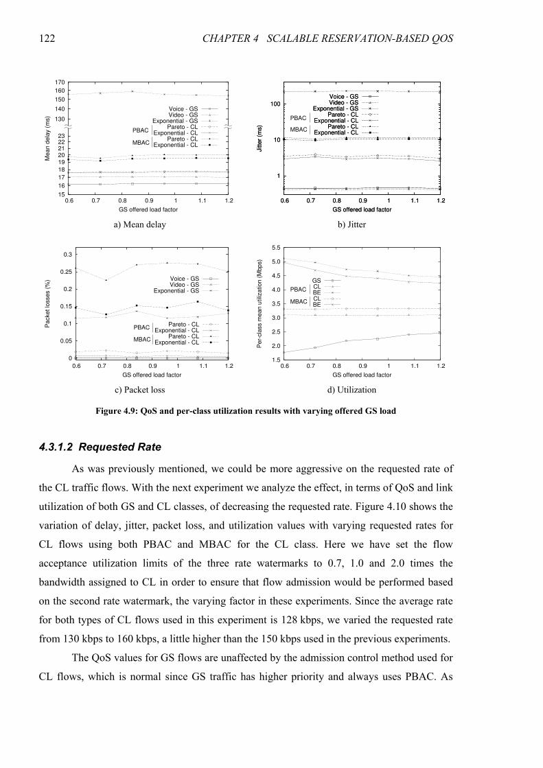
122 CHAPTER 4 SCALABLE RESERVATION-BASED QOS
4.3.1.2 Requested Rate
As was previously mentioned, we could be more aggressive on the requested rate of
the CL traffic flows. With the next experiment we analyze the effect, in terms of QoS and link
utilization of both GS and CL classes, of decreasing the requested rate. Figure 4.10 shows the
variation of delay, jitter, packet loss, and utilization values with varying requested rates for
CL flows using both PBAC and MBAC for the CL class. Here we have set the flow
acceptance utilization limits of the three rate watermarks to 0.7, 1.0 and 2.0 times the
bandwidth assigned to CL in order to ensure that flow admission would be performed based
on the second rate watermark, the varying factor in these experiments. Since the average rate
for both types of CL flows used in this experiment is 128 kbps, we varied the requested rate
from 130 kbps to 160 kbps, a little higher than the 150 kbps used in the previous experiments.
The QoS values for GS flows are unaffected by the admission control method used for
CL flows, which is normal since GS traffic has higher priority and always uses PBAC. As
170
160
150
140
130
23 22 21 20 19
18
17
16
15 0.6 0.7 0.8 0.9 1 1.1 1.2
Mean d
ela
y (
ms)
GS offered load factor
Voice - GSVideo - GS
Exponential - GSPareto - CL
Exponential - CLPareto - CL
Exponential - CL
PBAC
MBAC
1
10
100
0.6 0.7 0.8 0.9 1 1.1 1.2
Jitte
r (m
s)
GS offered load factor
Voice - GSVideo - GS
Exponential - GSPareto - CL
Exponential - CLPareto - CL
Exponential - CL
1
10
100
0.6 0.7 0.8 0.9 1 1.1 1.2
Jitte
r (m
s)
GS offered load factor
Voice - GSVideo - GS
Exponential - GSPareto - CL
Exponential - CLPareto - CL
Exponential - CL
PBAC
MBAC
a) Mean delay b) Jitter
0
0.05
0.1
0.15
0.2
0.25
0.3
0.6 0.7 0.8 0.9 1 1.1 1.2
Packet lo
sses (
%)
GS offered load factor
Voice - GSVideo - GS
Exponential - GS
Pareto - CLExponential - CL
Pareto - CLExponential - CL
PBAC
MBAC
1.5
2.0
2.5
3.0
3.5
4.0
4.5
5.0
5.5
0.6 0.7 0.8 0.9 1 1.1 1.2
Per-
cla
ss m
ean u
tiliz
ation (
Mbps)
GS offered load factor
GSCLBECLBE
PBAC
MBAC
c) Packet loss d) Utilization
Figure 4.9: QoS and per-class utilization results with varying offered GS load
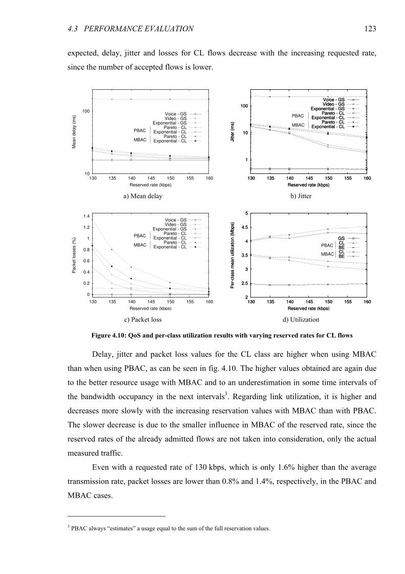
4.3 PERFORMANCE EVALUATION 123
expected, delay, jitter and losses for CL flows decrease with the increasing requested rate,
since the number of accepted flows is lower.
Delay, jitter and packet loss values for the CL class are higher when using MBAC
than when using PBAC, as can be seen in fig. 4.10. The higher values obtained are again due
to the better resource usage with MBAC and to an underestimation in some time intervals of
the bandwidth occupancy in the next intervals3. Regarding link utilization, it is higher and
decreases more slowly with the increasing reservation values with MBAC than with PBAC.
The slower decrease is due to the smaller influence in MBAC of the reserved rate, since the
reserved rates of the already admitted flows are not taken into consideration, only the actual
measured traffic.
Even with a requested rate of 130 kbps, which is only 1.6% higher than the average
transmission rate, packet losses are lower than 0.8% and 1.4%, respectively, in the PBAC and
MBAC cases.
3 PBAC always “estimates” a usage equal to the sum of the full reservation values.
10
100
130 135 140 145 150 155 160
Mean d
ela
y (
ms)
Reserved rate (kbps)
Voice - GSVideo - GS
Exponential - GSPareto - CL
Exponential - CLPareto - CL
Exponential - CLMBAC
PBAC
1
10
100
130 135 140 145 150 155 160
Jitte
r (m
s)
Reserved rate (kbps)
Voice - GSVideo - GS
Exponential - GSPareto - CL
Exponential - CLPareto - CL
Exponential - CL
1
10
100
130 135 140 145 150 155 160
Jitte
r (m
s)
Reserved rate (kbps)
Voice - GSVideo - GS
Exponential - GSPareto - CL
Exponential - CLPareto - CL
Exponential - CLMBAC
PBAC
a) Mean delay b) Jitter
0
0.2
0.4
0.6
0.8
1
1.2
1.4
130 135 140 145 150 155 160
Packet lo
sses (
%)
Reserved rate (kbps)
Voice - GSVideo - GS
Exponential - GSPareto - CL
Exponential - CLPareto - CL
Exponential - CLMBAC
PBAC
2
2.5
3
3.5
4
4.5
5
130 135 140 145 150 155 160
Per-
cla
ss m
ean u
tiliz
ation (
Mbps)
Reserved rate (kbps)
GSCLBECLBE
2
2.5
3
3.5
4
4.5
5
130 135 140 145 150 155 160
Per-
cla
ss m
ean u
tiliz
ation (
Mbps)
Reserved rate (kbps)
GSCLBECLBE
PBAC
MBAC
c) Packet loss d) Utilization
Figure 4.10: QoS and per-class utilization results with varying reserved rates for CL flows
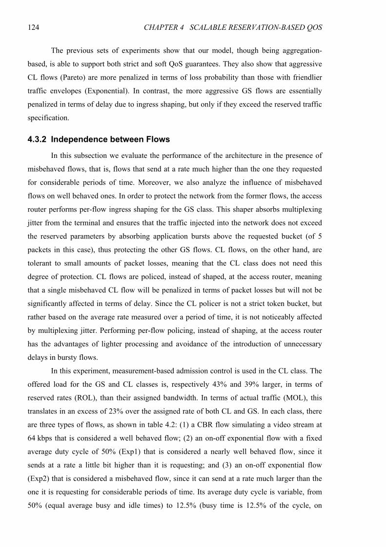
124 CHAPTER 4 SCALABLE RESERVATION-BASED QOS
The previous sets of experiments show that our model, though being aggregation-
based, is able to support both strict and soft QoS guarantees. They also show that aggressive
CL flows (Pareto) are more penalized in terms of loss probability than those with friendlier
traffic envelopes (Exponential). In contrast, the more aggressive GS flows are essentially
penalized in terms of delay due to ingress shaping, but only if they exceed the reserved traffic
specification.
4.3.2 Independence between Flows
In this subsection we evaluate the performance of the architecture in the presence of
misbehaved flows, that is, flows that send at a rate much higher than the one they requested
for considerable periods of time. Moreover, we also analyze the influence of misbehaved
flows on well behaved ones. In order to protect the network from the former flows, the access
router performs per-flow ingress shaping for the GS class. This shaper absorbs multiplexing
jitter from the terminal and ensures that the traffic injected into the network does not exceed
the reserved parameters by absorbing application bursts above the requested bucket (of 5
packets in this case), thus protecting the other GS flows. CL flows, on the other hand, are
tolerant to small amounts of packet losses, meaning that the CL class does not need this
degree of protection. CL flows are policed, instead of shaped, at the access router, meaning
that a single misbehaved CL flow will be penalized in terms of packet losses but will not be
significantly affected in terms of delay. Since the CL policer is not a strict token bucket, but
rather based on the average rate measured over a period of time, it is not noticeably affected
by multiplexing jitter. Performing per-flow policing, instead of shaping, at the access router
has the advantages of lighter processing and avoidance of the introduction of unnecessary
delays in bursty flows.
In this experiment, measurement-based admission control is used in the CL class. The
offered load for the GS and CL classes is, respectively 43% and 39% larger, in terms of
reserved rates (ROL), than their assigned bandwidth. In terms of actual traffic (MOL), this
translates in an excess of 23% over the assigned rate of both CL and GS. In each class, there
are three types of flows, as shown in table 4.2: (1) a CBR flow simulating a video stream at
64 kbps that is considered a well behaved flow; (2) an on-off exponential flow with a fixed
average duty cycle of 50% (Exp1) that is considered a nearly well behaved flow, since it
sends at a rate a little bit higher than it is requesting; and (3) an on-off exponential flow
(Exp2) that is considered a misbehaved flow, since it can send at a rate much larger than the
one it is requesting for considerable periods of time. Its average duty cycle is variable, from
50% (equal average busy and idle times) to 12.5% (busy time is 12.5% of the cycle, on
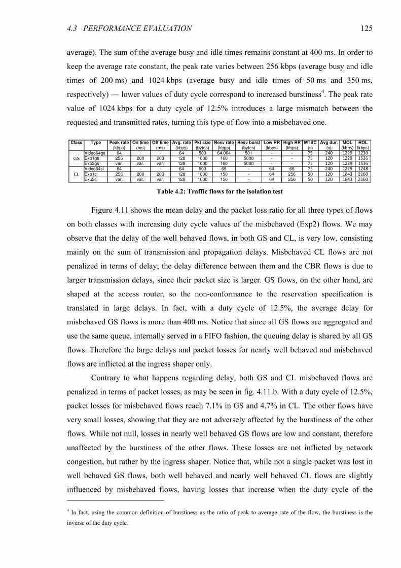
4.3 PERFORMANCE EVALUATION 125
average). The sum of the average busy and idle times remains constant at 400 ms. In order to
keep the average rate constant, the peak rate varies between 256 kbps (average busy and idle
times of 200 ms) and 1024 kbps (average busy and idle times of 50 ms and 350 ms,
respectively) — lower values of duty cycle correspond to increased burstiness4. The peak rate
value of 1024 kbps for a duty cycle of 12.5% introduces a large mismatch between the
requested and transmitted rates, turning this type of flow into a misbehaved one.
Figure 4.11 shows the mean delay and the packet loss ratio for all three types of flows
on both classes with increasing duty cycle values of the misbehaved (Exp2) flows. We may
observe that the delay of the well behaved flows, in both GS and CL, is very low, consisting
mainly on the sum of transmission and propagation delays. Misbehaved CL flows are not
penalized in terms of delay; the delay difference between them and the CBR flows is due to
larger transmission delays, since their packet size is larger. GS flows, on the other hand, are
shaped at the access router, so the non-conformance to the reservation specification is
translated in large delays. In fact, with a duty cycle of 12.5%, the average delay for
misbehaved GS flows is more than 400 ms. Notice that since all GS flows are aggregated and
use the same queue, internally served in a FIFO fashion, the queuing delay is shared by all GS
flows. Therefore the large delays and packet losses for nearly well behaved and misbehaved
flows are inflicted at the ingress shaper only.
Contrary to what happens regarding delay, both GS and CL misbehaved flows are
penalized in terms of packet losses, as may be seen in fig. 4.11.b. With a duty cycle of 12.5%,
packet losses for misbehaved flows reach 7.1% in GS and 4.7% in CL. The other flows have
very small losses, showing that they are not adversely affected by the burstiness of the other
flows. While not null, losses in nearly well behaved GS flows are low and constant, therefore
unaffected by the burstiness of the other flows. These losses are not inflicted by network
congestion, but rather by the ingress shaper. Notice that, while not a single packet was lost in
well behaved GS flows, both well behaved and nearly well behaved CL flows are slightly
influenced by misbehaved flows, having losses that increase when the duty cycle of the 4 In fact, using the common definition of burstiness as the ratio of peak to average rate of the flow, the burstiness is the
inverse of the duty cycle.
Table 4.2: Traffic flows for the isolation test
Class Type Peak rate On time Off time Avg. rate Pkt size Resv rate Resv burst Low RR High RR MTBC Avg dur. MOL ROL
(kbps) (ms) (ms) (kbps) (bytes) (kbps) (bytes) (kbps) (kbps) (s) (s) (kbps) (kbps)
GSVideo64gs 64 - - 64 500 64.064 501 - - 75 240 1229 1230Exp1gs 256 200 200 128 1000 160 5000 - - 75 120 1229 1536Exp2gs var. var. var. 128 1000 160 5000 - - 75 120 1229 1536
CLVideo64cl 64 - - 64 500 65 - 64 66 75 240 1229 1248Exp1cl 256 200 200 128 1000 150 - 64 256 50 120 1843 2160Exp2cl var. var. var. 128 1000 150 - 64 256 50 120 1843 2160
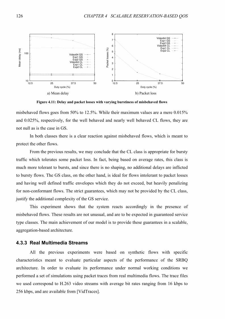
126 CHAPTER 4 SCALABLE RESERVATION-BASED QOS
misbehaved flows goes from 50% to 12.5%. While their maximum values are a mere 0.015%
and 0.025%, respectively, for the well behaved and nearly well behaved CL flows, they are
not null as is the case in GS.
In both classes there is a clear reaction against misbehaved flows, which is meant to
protect the other flows.
From the previous results, we may conclude that the CL class is appropriate for bursty
traffic which tolerates some packet loss. In fact, being based on average rates, this class is
much more tolerant to bursts, and since there is no shaping, no additional delays are inflicted
to bursty flows. The GS class, on the other hand, is ideal for flows intolerant to packet losses
and having well defined traffic envelopes which they do not exceed, but heavily penalizing
for non-conformant flows. The strict guarantees, which may not be provided by the CL class,
justify the additional complexity of the GS service.
This experiment shows that the system reacts accordingly in the presence of
misbehaved flows. These results are not unusual, and are to be expected in guaranteed service
type classes. The main achievement of our model is to provide these guarantees in a scalable,
aggregation-based architecture.
4.3.3 Real Multimedia Streams
All the previous experiments were based on synthetic flows with specific
characteristics meant to evaluate particular aspects of the performance of the SRBQ
architecture. In order to evaluate its performance under normal working conditions we
performed a set of simulations using packet traces from real multimedia flows. The trace files
we used correspond to H.263 video streams with average bit rates ranging from 16 kbps to
256 kbps, and are available from [VidTraces].
10
100
12.5 25 37.5 50
Mean d
ela
y (
ms)
Duty cycle (%)
Video64 GSExp1 GSExp2 GS
Video64 CLExp1 CLExp2 CL
0
1
2
3
4
5
6
7
8
12.5 25 37.5 50
Packet lo
sses (
%)
Duty cycle (%)
Video64 GSExp1 GSExp2 GS
Video64 CLExp1 CLExp2 CL
a) Mean delay b) Packet loss
Figure 4.11: Delay and packet losses with varying burstiness of misbehaved flows
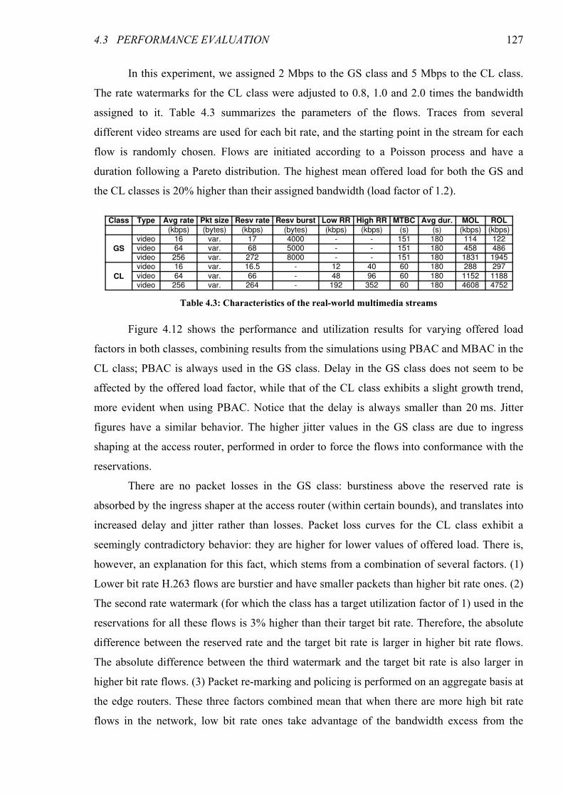
4.3 PERFORMANCE EVALUATION 127
In this experiment, we assigned 2 Mbps to the GS class and 5 Mbps to the CL class.
The rate watermarks for the CL class were adjusted to 0.8, 1.0 and 2.0 times the bandwidth
assigned to it. Table 4.3 summarizes the parameters of the flows. Traces from several
different video streams are used for each bit rate, and the starting point in the stream for each
flow is randomly chosen. Flows are initiated according to a Poisson process and have a
duration following a Pareto distribution. The highest mean offered load for both the GS and
the CL classes is 20% higher than their assigned bandwidth (load factor of 1.2).
Figure 4.12 shows the performance and utilization results for varying offered load
factors in both classes, combining results from the simulations using PBAC and MBAC in the
CL class; PBAC is always used in the GS class. Delay in the GS class does not seem to be
affected by the offered load factor, while that of the CL class exhibits a slight growth trend,
more evident when using PBAC. Notice that the delay is always smaller than 20 ms. Jitter
figures have a similar behavior. The higher jitter values in the GS class are due to ingress
shaping at the access router, performed in order to force the flows into conformance with the
reservations.
There are no packet losses in the GS class: burstiness above the reserved rate is
absorbed by the ingress shaper at the access router (within certain bounds), and translates into
increased delay and jitter rather than losses. Packet loss curves for the CL class exhibit a
seemingly contradictory behavior: they are higher for lower values of offered load. There is,
however, an explanation for this fact, which stems from a combination of several factors. (1)
Lower bit rate H.263 flows are burstier and have smaller packets than higher bit rate ones. (2)
The second rate watermark (for which the class has a target utilization factor of 1) used in the
reservations for all these flows is 3% higher than their target bit rate. Therefore, the absolute
difference between the reserved rate and the target bit rate is larger in higher bit rate flows.
The absolute difference between the third watermark and the target bit rate is also larger in
higher bit rate flows. (3) Packet re-marking and policing is performed on an aggregate basis at
the edge routers. These three factors combined mean that when there are more high bit rate
flows in the network, low bit rate ones take advantage of the bandwidth excess from the
Table 4.3: Characteristics of the real-world multimedia streams
Class Type Avg rate Pkt size Resv rate Resv burst Low RR High RR MTBC Avg dur. MOL ROL
(kbps) (bytes) (kbps) (bytes) (kbps) (kbps) (s) (s) (kbps) (kbps)
GS
video 16 var. 17 4000 - - 151 180 114 122video 64 var. 68 5000 - - 151 180 458 486video 256 var. 272 8000 - - 151 180 1831 1945
CL
video 16 var. 16.5 - 12 40 60 180 288 297
video 64 var. 66 - 48 96 60 180 1152 1188video 256 var. 264 - 192 352 60 180 4608 4752
128 CHAPTER 4 SCALABLE RESERVATION-BASED QOS
higher bit rate ones, therefore decreasing their loss ratio. This fact has a much higher weight
in the overall packet loss ratio than the (minimal) amount of network congestion.
The utilization of each class, as expected, grows with the offered load. With a load
factor of 1.2, the mean utilization of the GS class is 1.3 Mbps (65%), and that of the CL class
is 3.8 Mbps (75%) when using PBAC and 3.6 Mbps (72%) when using MBAC. The lower
utilization with MBAC than with PBAC has a simple explanation. The reserved rate (second
watermark) for these flows is very close to their target bit rate (only 3% higher). The MBAC
target utilization factor is 95%; this means that most of the time the estimated bandwidth will
be higher than 95% of the sum of the reservations, leading to lower utilization figures when
using MBAC.
The results presented in the previous paragraphs show that the SRBQ architecture is
able to meet the QoS requirements of the supported service classes when using real-world
multimedia flows.
15
16
17
18
19
20
0.6 0.7 0.8 0.9 1 1.1 1.2
Mean d
ela
y (
ms)
Offered load factors
GSPBAC CLMBAC CL
0
5
10
15
20
0.6 0.7 0.8 0.9 1 1.1 1.2
Jitte
r (m
s)
Offered load factors
GSPBAC CLMBAC CL
a) Mean delay b) Jitter
0
0.002
0.004
0.006
0.008
0.01
0.012
0.014
0.6 0.7 0.8 0.9 1 1.1 1.2
Packet lo
sses (
%)
Offered load factors
GSPBAC CLMBAC CL
0.5
1
1.5
2
2.5
3
3.5
4
0.6 0.7 0.8 0.9 1 1.1 1.2
Per-
cla
ss m
ean u
tiliz
ation (
Mbps)
Offered load factors
GSPBAC CLMBAC CL
c) Packet loss d) Utilization
Figure 4.12: QoS and utilization results with varying offered loads using real video flows
4.3 PERFORMANCE EVALUATION 129
4.3.4 Scalability
SRBQ combines DiffServ-like aggregate packet processing (classification, scheduling,
policing and shaping), whose scalability properties are well known, with a model of per-flow
signaling-based resource reservation carefully designed to have message processing times that
are low and algorithmically independent on the number of simultaneous flows. This
independence property is fundamental to the scalability of the signaling protocol, as it implies
that the overall necessary processing power in face of the number of simultaneous flows can
be upper bounded by a linear curve. However, an evaluation of SRBQ would not be complete
without a measurement of processing delay of the signaling messages, necessary to ascertain
the feasibility of the protocol as of today.
Usually, such an evaluation would be undertaken in a physical testbed using a
prototype implementation. An event-driven network simulator, such as ns-2, in not generally
appropriate for such measurements, as the simulated clock progresses independently of the
wall clock, and all processing appears to be instantaneous. However, if the implementation of
a piece of code in the simulator is close enough to what a real implementation would be, a
meaningful measure of the processing delay associated to that piece of code may be obtained
by ignoring the simulation clock and using the system clock instead. We decided to take this
approach in order to avoid the burden of re-implementing SRBQ in a real operating system
and setting up the testbed.
In this experiment we used the same set of flows of section 4.3.1 and varied the load
factor between 0.033 and 33.3 in order to evaluate the processing delay with different loads.
However, since we wanted to maintain the flow acceptance ratio, the upper bounds on the
aggregate values were varied in the same proportion. Using the TSC (Time Stamp Counter)
register of the processor, which counts the number of clock cycles since boot-up, we
measured the processing delay of SResv messages, including both initial and refreshments of
accepted flows. The processing delay was obtained by dividing the number of elapsed cycles
by the Central Processing Unit’s (CPU) clock frequency.
Figure 4.13 shows the processing delay of SResv messages for different values of the
load factor. These delays were measured in an AMD Athlon XP running at 2095 MHz (a low-
end desktop processor by today’s standards), and include the generation of the messages to be
forwarded to the next hop. There were roughly 7 refresh messages for each initial SResv, on
average. About 1800 messages were processed per simulated second at intermediate nodes
with load factor 33.3. The results exhibited an unexpected behavior: even though no piece of
code inside the SResv message processing routine depends on the number of simultaneous
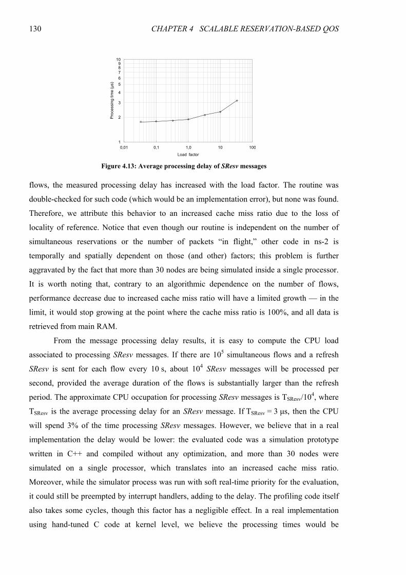
130 CHAPTER 4 SCALABLE RESERVATION-BASED QOS
flows, the measured processing delay has increased with the load factor. The routine was
double-checked for such code (which would be an implementation error), but none was found.
Therefore, we attribute this behavior to an increased cache miss ratio due to the loss of
locality of reference. Notice that even though our routine is independent on the number of
simultaneous reservations or the number of packets “in flight,” other code in ns-2 is
temporally and spatially dependent on those (and other) factors; this problem is further
aggravated by the fact that more than 30 nodes are being simulated inside a single processor.
It is worth noting that, contrary to an algorithmic dependence on the number of flows,
performance decrease due to increased cache miss ratio will have a limited growth — in the
limit, it would stop growing at the point where the cache miss ratio is 100%, and all data is
retrieved from main RAM.
From the message processing delay results, it is easy to compute the CPU load
associated to processing SResv messages. If there are 105 simultaneous flows and a refresh
SResv is sent for each flow every 10 s, about 104 SResv messages will be processed per
second, provided the average duration of the flows is substantially larger than the refresh
period. The approximate CPU occupation for processing SResv messages is TSResv/104, where
TSResv is the average processing delay for an SResv message. If TSResv = 3 µs, then the CPU
will spend 3% of the time processing SResv messages. However, we believe that in a real
implementation the delay would be lower: the evaluated code was a simulation prototype
written in C++ and compiled without any optimization, and more than 30 nodes were
simulated on a single processor, which translates into an increased cache miss ratio.
Moreover, while the simulator process was run with soft real-time priority for the evaluation,
it could still be preempted by interrupt handlers, adding to the delay. The profiling code itself
also takes some cycles, though this factor has a negligible effect. In a real implementation
using hand-tuned C code at kernel level, we believe the processing times would be
1
10
0,01 0,10 1,00 10,00 100,00
Load factor
Processing time (µs)
0,01 0,1 1,0 10 100
2
3
4
5
6
7
89
Figure 4.13: Average processing delay of SResv messages
4.4 COMPARISON BETWEEN SRBQ AND RSVPRAGG 131
significantly lower without any modification to the signaling protocol. Further improvements
could still be obtained by a simplification of the protocol using fixed format messages, which
are much simpler to parse, instead of the object-oriented RSVP extension approach.
4.4 Comparison between SRBQ and RSVPRAgg
This section presents a comparison between SRBQ and RSVPRAgg, the IETF
proposal for a scalable aggregation-based QoS architecture with reservations. We analyze the
QoS guarantees, resource utilization and scalability of both models in order to evaluate their
relative merits and shortcomings, as well as their suitability to replace the reference
RSVP/IntServ architecture, which suffers from scalability problems that disallow its usage in
high traffic core networks. We perform both a qualitative comparison, based on the nature of
the architectures, and a quantitative comparison, based on simulation results.
A mapping between the QoS architectures needs to be performed in order to obtain a
meaningful comparison. The aggregation regions of RSVPRAgg and the non-aggregated
RSVP regions correspond to the core and access domains of SRBQ, respectively; the
aggregators and deaggregators in RSVPRAgg correspond to edge routers in SRBQ. The
network topology used in the simulations is the same given this mapping.
4.4.1 Qualitative Comparison
Both the RSVPRAgg and the SRBQ model aim at providing QoS levels comparable to
those of the RSVP/IntServ model but, unlike this one, in a scalable manner. Resorting only to
the nature of the architectures, we may state that both are able to support strict and soft QoS
guarantees, since no flow (not belonging to the best effort class) is admitted in the network
when the available end-to-end network resources are not sufficient. The admission control
algorithm for the CL classes is token bucket based in RSVPRAgg and average rate
watermarks based in SRBQ. Both of these architectures make use of aggregation of flows in
order to achieve high efficiency in packet classification and scheduling, and both of them use
the DSCP field of the IP header to this end. The approach to reducing the signaling processing
load is radically different, though.
The core routers in the RSVPRAgg architecture only need to store the state of each
aggregate. Contrasting to this low amount of state, the one stored in the SRBQ architecture is
per-flow. However, considering the available routers nowadays, this does not seem to be a
limiting factor of the SRBQ architecture, as previously demonstrated. A more scalability-
limiting factor at the core routers would be the lookup of the stored flow information, based
on the 5-tuple parameters that specify the flow, when the number of flows is very high. Since
132 CHAPTER 4 SCALABLE RESERVATION-BASED QOS
the SRBQ architecture overcomes this problem by using the labels, the existence of per-flow
reservation structures is not a limitation. The scalability of the classification and scheduling
procedures at the core nodes is similar in both architectures, since they are performed on a
per-aggregate basis, according to the DSCP of the flows. At the edge routers, classification is
much lighter in the SRBQ model, since no per-flow mapping needs to be performed. As
scheduling on both architectures is performed per-class, using simple queuing disciplines in
the underlying DiffServ-like infrastructure, the efficiency is comparable. At the access
routers, packet classification is performed per-flow in both models. The processing load
involved for classification is, therefore, similar; however, it may be highly reduced in SRBQ
if labels are used in data packets (which is always true in the GS class). Packet scheduling is
usually more efficient in SRBQ, since it is based on the DSCP, whereas in RSVPRAgg, at the
access routers (therefore outside the aggregation regions), usually Weighted Fair Queuing
(WFQ) or a similar discipline is used.
One disadvantage of the SRBQ model is the mandatory shaping of the GS class at
every router, and the ingress shaping of this class at the edge routers. Notice, however, that
since the whole class is treated as a single flow, shaping may be performed very efficiently,
and may trivially be implemented in dedicated hardware.
Both models have a soft-state approach to reservations, meaning that a reservation that
is neither explicitly terminated nor refreshed for a certain period will timeout and be removed.
This soft-state character provides them with adaptability to changing network conditions (e.g.,
route changes) and failures which inevitably occur in a dynamic Internet. In order to
efficiently implement reservation expiration timers, a specific timer algorithm was developed
for SRBQ having O(1) computational complexity. RSVPRAgg, like RSVP, makes use of
generic timers, but has a much lower number of (aggregate) reservations to manage at core
nodes. At edge nodes, however, reservations are per-flow, and generic timers impose a
scalability limitation to RSVPRAgg.
The approach at making signaling processing scalable is very different in these two
architectures. In SRBQ the end-to-end character of reservation signaling is retained, and
scalability is achieved by the use of computationally efficient techniques and algorithms (like
labels and efficient timers). In RSVPRAgg, end-to-end reservations are aggregated, reducing
the signaling processing at the core to that needed to maintain and update aggregate
reservations, whose updates are performed in bulk quantities in order to reduce the signaling
load. This approach has two disadvantages: (1) the number of signaling messages processed at
the edge nodes of the aggregation region, which may be a high-traffic transit domain, is even
4.4 COMPARISON BETWEEN SRBQ AND RSVPRAGG 133
higher than in the case of regular RSVP, since both end-to-end and aggregate messages must
be processed; worse, packet classification at the edge is per-flow; and (2) the reduction in
signaling is highly dependent on the bulk size, but large bulk sizes lead to a very poor
utilization of network resources.
In the SRBQ architecture the utilization of network resources is very high since the
reserved bandwidth always matches the bandwidth of the admitted traffic. The aggregation
efficiency in the RSVPRAgg architecture depends on the matching between the admitted
traffic and the aggregate reservation. If the bulk bandwidth is too large, the signaling load is
highly reduced but the network resources can be highly under-utilized. On the other hand,
with a small bulk size, the aggregate reserved bandwidth is close to that of the admitted traffic
(resources are not wasted), but the signaling load is very high, similar to that of per-flow
reservations.
Concerning reservation setup delays, they may be divided in two components: (1) the
delay related to message exchange between routers and (2) the processing time for these
messages. In the SRBQ model, the first component of the delay is one end-to-end round trip
time. In RSVPRAgg, it is equivalent to one end-to-end round trip time in the best case, when
the corresponding aggregate already exists and has enough bandwidth to accommodate the
end-to-end flow; when the aggregate exists but has not enough bandwidth, a round trip time
for the aggregation region is added; when the aggregate does not yet exist, two round trip
times for the aggregation region must be added. The second component of the delay is more
difficult to evaluate. In the SRBQ model it is approximately fixed for a given topology. In
RSVPRAgg it depends on several factors: (1) the need to modify the aggregate bandwidth;
(2) the ratio of routers in the aggregation region to the total number of routers in the end-to-
end path; (3) the number of end-to-end flows at the edge routers of the aggregation region and
at the routers outside this region; (4) the efficiency of the hashing functions used, and other
factors. In the end, we expect the high efficiency of signaling message processing in SRBQ
model to compensate the higher number of signaling messages processed.
4.4.2 Quantitative Comparison
As has been previously mentioned, we have implemented the SRBQ and RSVPRAgg
models in the ns-2 simulator. We will now present a quantitative comparison of these
architectures based on a series of simulation experiments performed with these
implementations. An existing implementation of RSVP for this simulator [Greis98] was also
used to obtain reference results.
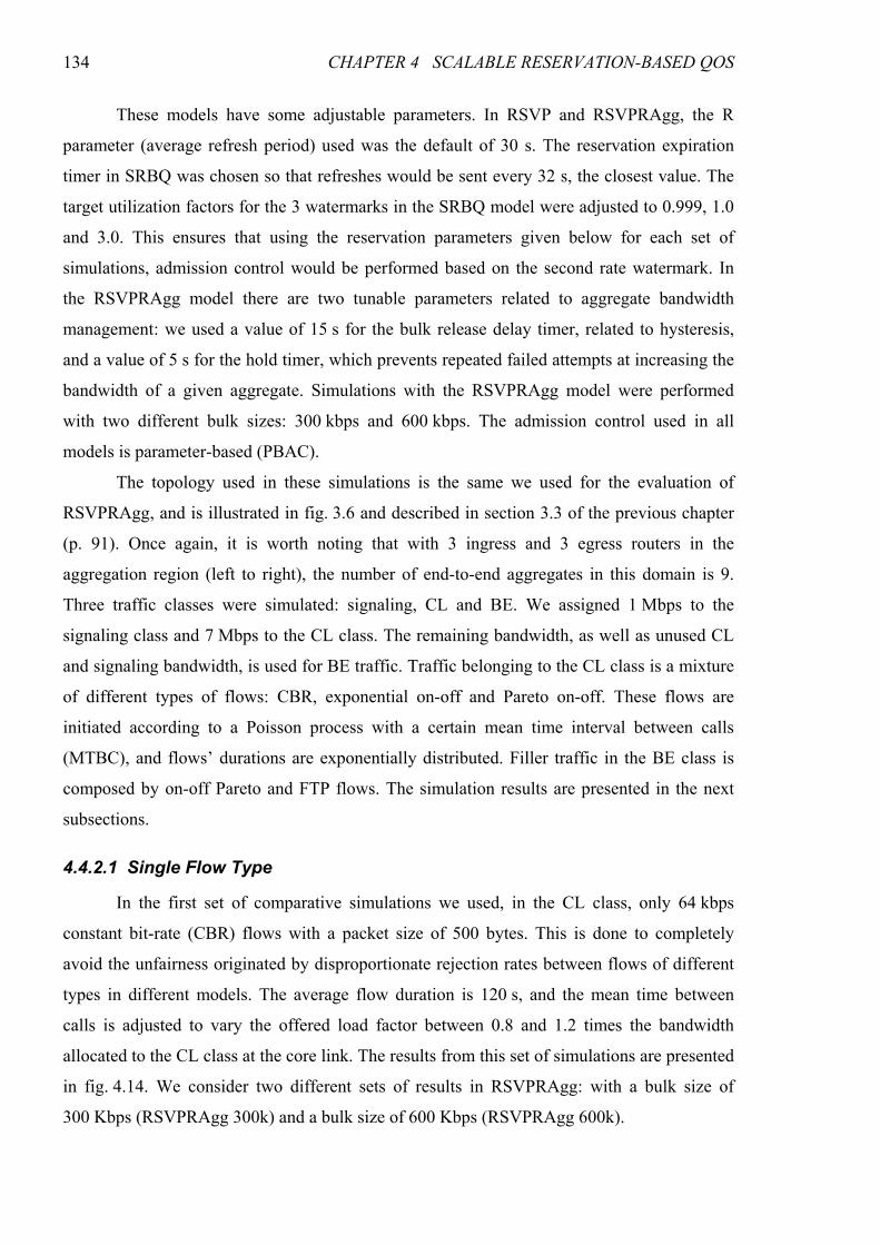
134 CHAPTER 4 SCALABLE RESERVATION-BASED QOS
These models have some adjustable parameters. In RSVP and RSVPRAgg, the R
parameter (average refresh period) used was the default of 30 s. The reservation expiration
timer in SRBQ was chosen so that refreshes would be sent every 32 s, the closest value. The
target utilization factors for the 3 watermarks in the SRBQ model were adjusted to 0.999, 1.0
and 3.0. This ensures that using the reservation parameters given below for each set of
simulations, admission control would be performed based on the second rate watermark. In
the RSVPRAgg model there are two tunable parameters related to aggregate bandwidth
management: we used a value of 15 s for the bulk release delay timer, related to hysteresis,
and a value of 5 s for the hold timer, which prevents repeated failed attempts at increasing the
bandwidth of a given aggregate. Simulations with the RSVPRAgg model were performed
with two different bulk sizes: 300 kbps and 600 kbps. The admission control used in all
models is parameter-based (PBAC).
The topology used in these simulations is the same we used for the evaluation of
RSVPRAgg, and is illustrated in fig. 3.6 and described in section 3.3 of the previous chapter
(p. 91). Once again, it is worth noting that with 3 ingress and 3 egress routers in the
aggregation region (left to right), the number of end-to-end aggregates in this domain is 9.
Three traffic classes were simulated: signaling, CL and BE. We assigned 1 Mbps to the
signaling class and 7 Mbps to the CL class. The remaining bandwidth, as well as unused CL
and signaling bandwidth, is used for BE traffic. Traffic belonging to the CL class is a mixture
of different types of flows: CBR, exponential on-off and Pareto on-off. These flows are
initiated according to a Poisson process with a certain mean time interval between calls
(MTBC), and flows’ durations are exponentially distributed. Filler traffic in the BE class is
composed by on-off Pareto and FTP flows. The simulation results are presented in the next
subsections.
4.4.2.1 Single Flow Type
In the first set of comparative simulations we used, in the CL class, only 64 kbps
constant bit-rate (CBR) flows with a packet size of 500 bytes. This is done to completely
avoid the unfairness originated by disproportionate rejection rates between flows of different
types in different models. The average flow duration is 120 s, and the mean time between
calls is adjusted to vary the offered load factor between 0.8 and 1.2 times the bandwidth
allocated to the CL class at the core link. The results from this set of simulations are presented
in fig. 4.14. We consider two different sets of results in RSVPRAgg: with a bulk size of
300 Kbps (RSVPRAgg 300k) and a bulk size of 600 Kbps (RSVPRAgg 600k).
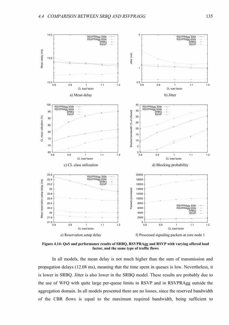
4.4 COMPARISON BETWEEN SRBQ AND RSVPRAGG 135
In all models, the mean delay is not much higher than the sum of transmission and
propagation delays (12.08 ms), meaning that the time spent in queues is low. Nevertheless, it
is lower in SRBQ. Jitter is also lower in the SRBQ model. These results are probably due to
the use of WFQ with quite large per-queue limits in RSVP and in RSVPRAgg outside the
aggregation domain. In all models presented there are no losses, since the reserved bandwidth
of the CBR flows is equal to the maximum required bandwidth, being sufficient to
13.0
13.5
14.0
0.8 0.9 1 1.1 1.2
Mean d
ela
y (
ms)
CL load factor
RSVPRAgg 300kRSVPRAgg 600k
SRBQRSVP
0.5
1
5
0.8 0.9 1 1.1 1.2
Jitte
r (m
s)
CL load factor
RSVPRAgg 300kRSVPRAgg 600k
SRBQRSVP
a) Mean delay b) Jitter
65
70
75
80
85
90
95
100
0.8 0.9 1 1.1 1.2
CL m
ean u
tiliz
ation (
%)
CL load factor
RSVPRAgg 300kRSVPRAgg 600k
SRBQRSVP
0
5
10
15
20
25
30
35
40
0.8 0.9 1 1.1 1.2
Blo
cked b
andw
idth
(%
of offere
d)
CL load factor
RSVPRAgg 300kRSVPRAgg 600k
SRBQRSVP
c) CL class utilization d) Blocking probability
21.6
21.8
22
22.2
22.4
22.6
22.8
23
23.2
23.4
23.6
0.8 0.9 1 1.1 1.2
Mean r
eserv
ation s
etu
p d
ela
y (
ms)
CL load factor
RSVPRAgg 300kRSVPRAgg 600k
SRBQRSVP
0
2000
4000
6000
8000
10000
12000
14000
16000
18000
20000
0.8 0.9 1 1.1 1.2
Packets
pro
cessed
CL load factor
RSVPRAgg 300kRSVPRAgg 600k
SRBQRSVP
e) Reservation setup delay f) Processed signaling packets at core node 1
Figure 4.14: QoS and performance results of SRBQ, RSVPRAgg and RSVP with varying offered load
factor, and the same type of traffic flows
136 CHAPTER 4 SCALABLE RESERVATION-BASED QOS
accommodate the accepted flows. Regarding the utilization of bandwidth allocated to the CL
class, it is much higher in SRBQ (similar to RSVP) than in RSVPRAgg. In the former, the
curve shows saturation around the offered load factor of 1, whereas in the latter there is no
visible saturation. In RSVPRAgg, the utilization is very noticeably lower with a bulk size of
600 kbps than with a bulk size of 300 kbps. Notice that a bulk size of 600 kbps is less than a
factor of 10 higher than the flow rates. This suggests that the use of larger bulk sizes in order
to increase the scalability would lead to very poor network resource utilization.
Corresponding to the lower utilization figures, the blocked bandwidth in the RSVPRAgg
model is higher than in SRBQ, and is higher when using larger bulk sizes. In SRBQ the
blocked bandwidth figures are similar to regular RSVP, since in both end-to-end reservations
are accepted up to the bandwidth reserved for the CL class, contrasting to the RSVPRAgg
model in which end-to-end reservations are only accepted up to the reserved rate of the
corresponding aggregate.
The reservation setup delay is another evaluated parameter. In SRBQ, it was measured
from the instant the reservation procedure is triggered by sending an SResv message to the
instant the corresponding SResvStat message is received at the sender, confirming the
successful establishment of the reservation. In RSVPRAgg and regular RSVP it is measured
from the instant the first Path message for the flow is emitted to the instant the corresponding
Resv arrives at the sender, indicating the existence of the reservation along the whole path,
given that the receiver sends a Resv message as soon as it receives the first Path message for a
new flow. Since the ns-2 simulator does not measure message processing times, the values
presented correspond only to the signaling packet exchange. The lowest setup times
correspond to SRBQ and RSVP, since in both models they correspond to a round trip time for
the messages, being larger in RSVP due to the larger message size. In RSVPRAgg, on the
other hand, when an aggregate does not exist or its bandwidth needs to be updated, additional
messages are exchanged inside the aggregation region, leading to higher end-to-end
reservation setup delays, which increase with decreasing bulk sizes. The reduction in
reservation setup time with increasing offered load factor and a bulk size of 300 kbps is
explained by the fact that more flows are being accepted into aggregates without modifying
their bandwidth, since a higher portion of those requiring bandwidth increase are rejected.
Notice that if processing times were measured, the reservation setup delay of regular RSVP
would be much higher than in the other two models.
The last parameter evaluated in this test is the number of signaling messages processed
at core node 1 (refer to fig. 3.6 in the previous chapter). The average refresh interval used for
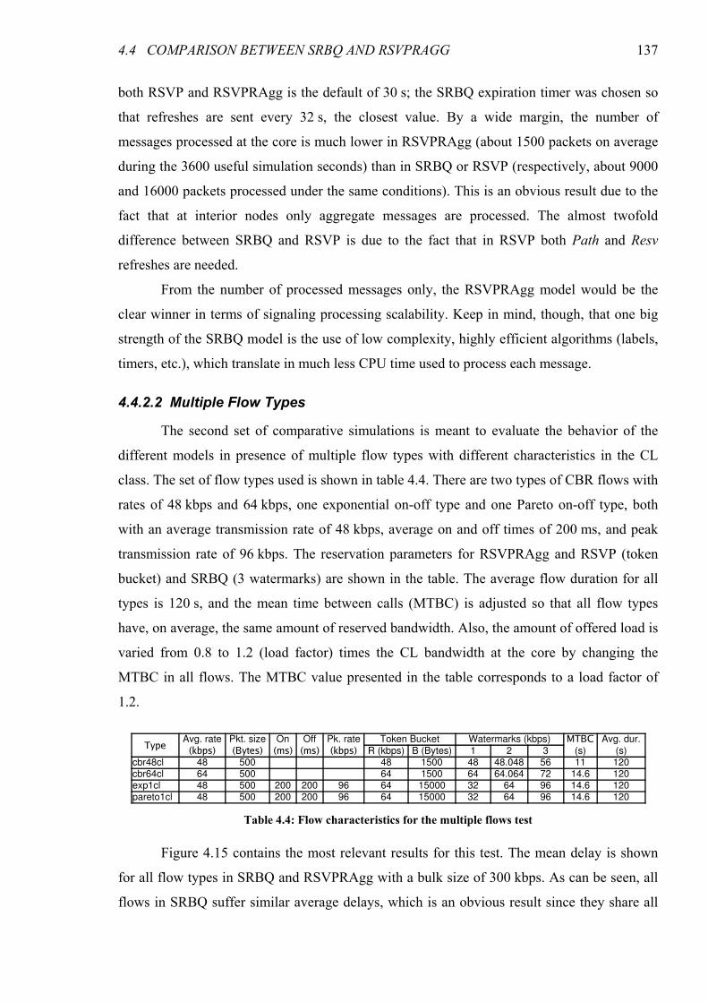
4.4 COMPARISON BETWEEN SRBQ AND RSVPRAGG 137
both RSVP and RSVPRAgg is the default of 30 s; the SRBQ expiration timer was chosen so
that refreshes are sent every 32 s, the closest value. By a wide margin, the number of
messages processed at the core is much lower in RSVPRAgg (about 1500 packets on average
during the 3600 useful simulation seconds) than in SRBQ or RSVP (respectively, about 9000
and 16000 packets processed under the same conditions). This is an obvious result due to the
fact that at interior nodes only aggregate messages are processed. The almost twofold
difference between SRBQ and RSVP is due to the fact that in RSVP both Path and Resv
refreshes are needed.
From the number of processed messages only, the RSVPRAgg model would be the
clear winner in terms of signaling processing scalability. Keep in mind, though, that one big
strength of the SRBQ model is the use of low complexity, highly efficient algorithms (labels,
timers, etc.), which translate in much less CPU time used to process each message.
4.4.2.2 Multiple Flow Types
The second set of comparative simulations is meant to evaluate the behavior of the
different models in presence of multiple flow types with different characteristics in the CL
class. The set of flow types used is shown in table 4.4. There are two types of CBR flows with
rates of 48 kbps and 64 kbps, one exponential on-off type and one Pareto on-off type, both
with an average transmission rate of 48 kbps, average on and off times of 200 ms, and peak
transmission rate of 96 kbps. The reservation parameters for RSVPRAgg and RSVP (token
bucket) and SRBQ (3 watermarks) are shown in the table. The average flow duration for all
types is 120 s, and the mean time between calls (MTBC) is adjusted so that all flow types
have, on average, the same amount of reserved bandwidth. Also, the amount of offered load is
varied from 0.8 to 1.2 (load factor) times the CL bandwidth at the core by changing the
MTBC in all flows. The MTBC value presented in the table corresponds to a load factor of
1.2.
Figure 4.15 contains the most relevant results for this test. The mean delay is shown
for all flow types in SRBQ and RSVPRAgg with a bulk size of 300 kbps. As can be seen, all
flows in SRBQ suffer similar average delays, which is an obvious result since they share all
Table 4.4: Flow characteristics for the multiple flows test
TypeAvg. rate Pkt. size On Off Pk. rate Token Bucket Watermarks (kbps) MTBC Avg. dur.
(kbps) (Bytes) (ms) (ms) (kbps) R (kbps) B (Bytes) 1 2 3 (s) (s)cbr48cl 48 500 48 1500 48 48.048 56 11 120cbr64cl 64 500 64 1500 64 64.064 72 14.6 120exp1cl 48 500 200 200 96 64 15000 32 64 96 14.6 120pareto1cl 48 500 200 200 96 64 15000 32 64 96 14.6 120
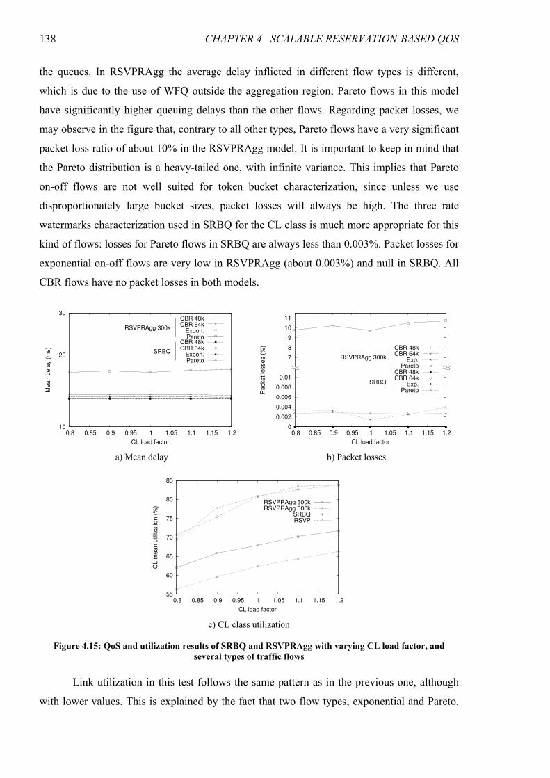
138 CHAPTER 4 SCALABLE RESERVATION-BASED QOS
the queues. In RSVPRAgg the average delay inflicted in different flow types is different,
which is due to the use of WFQ outside the aggregation region; Pareto flows in this model
have significantly higher queuing delays than the other flows. Regarding packet losses, we
may observe in the figure that, contrary to all other types, Pareto flows have a very significant
packet loss ratio of about 10% in the RSVPRAgg model. It is important to keep in mind that
the Pareto distribution is a heavy-tailed one, with infinite variance. This implies that Pareto
on-off flows are not well suited for token bucket characterization, since unless we use
disproportionately large bucket sizes, packet losses will always be high. The three rate
watermarks characterization used in SRBQ for the CL class is much more appropriate for this
kind of flows: losses for Pareto flows in SRBQ are always less than 0.003%. Packet losses for
exponential on-off flows are very low in RSVPRAgg (about 0.003%) and null in SRBQ. All
CBR flows have no packet losses in both models.
Link utilization in this test follows the same pattern as in the previous one, although
with lower values. This is explained by the fact that two flow types, exponential and Pareto,
10
20
30
0.8 0.85 0.9 0.95 1 1.05 1.1 1.15 1.2
Mean d
ela
y (
ms)
CL load factor
Agg 300k CBR 48kAgg 300k CBR 64k
Agg 300k Exp.Agg 300k ParetoSRBQ CBR 48kSRBQ CBR 64k
SRBQ Exp.SRBQ Pareto
CBR 48kCBR 64k
Expon.Pareto
CBR 48kCBR 64k
Expon.Pareto
RSVPRAgg 300k
SRBQ
0
0.002
0.004
0.006
0.008
0.01
7
8
9
10
11
0.8 0.85 0.9 0.95 1 1.05 1.1 1.15 1.2
Packet lo
sses (
%)
CL load factor
CBR 48kCBR 64k
Exp.Pareto
CBR 48kCBR 64k
Exp.Pareto
RSVPRAgg 300k
SRBQ
a) Mean delay b) Packet losses
55
60
65
70
75
80
85
0.8 0.85 0.9 0.95 1 1.05 1.1 1.15 1.2
CL m
ean u
tiliz
ation (
%)
CL load factor
RSVPRAgg 300kRSVPRAgg 600k
SRBQRSVP
c) CL class utilization
Figure 4.15: QoS and utilization results of SRBQ and RSVPRAgg with varying CL load factor, and
several types of traffic flows
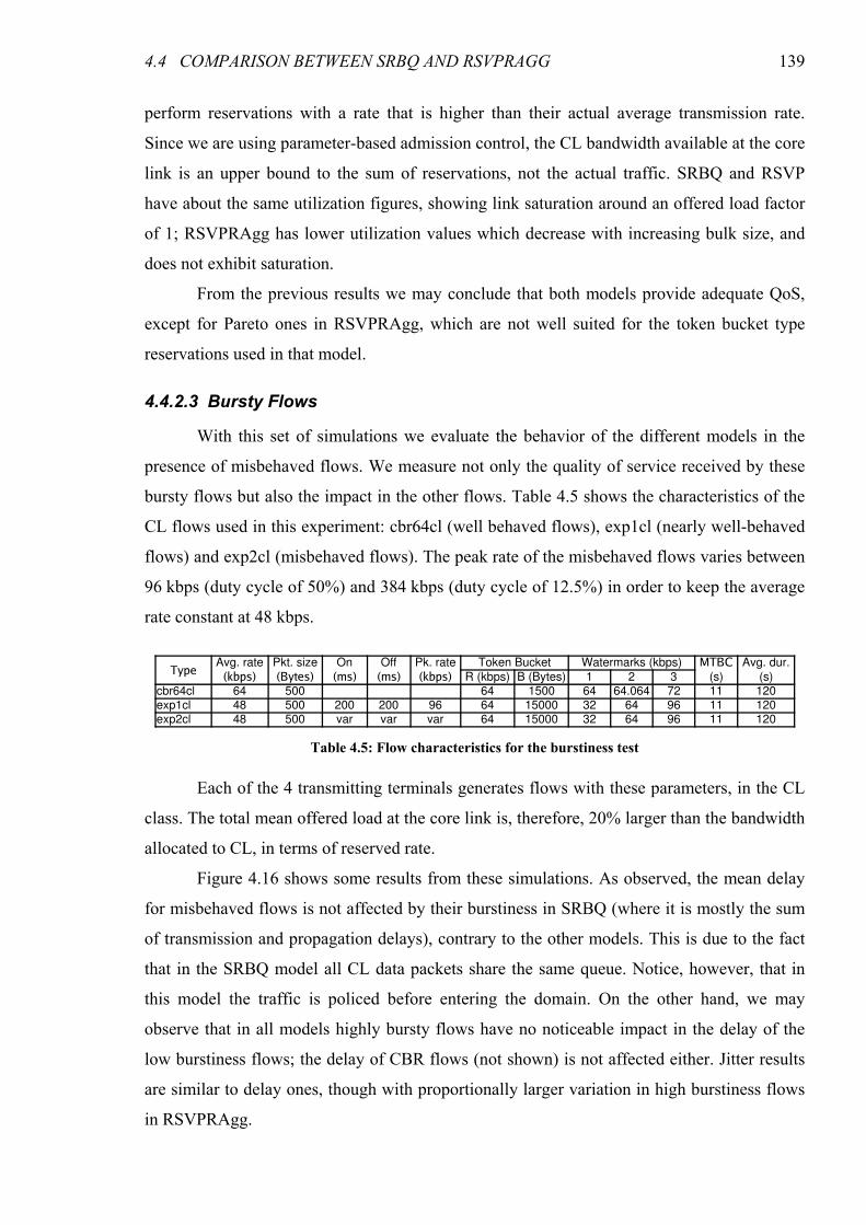
4.4 COMPARISON BETWEEN SRBQ AND RSVPRAGG 139
perform reservations with a rate that is higher than their actual average transmission rate.
Since we are using parameter-based admission control, the CL bandwidth available at the core
link is an upper bound to the sum of reservations, not the actual traffic. SRBQ and RSVP
have about the same utilization figures, showing link saturation around an offered load factor
of 1; RSVPRAgg has lower utilization values which decrease with increasing bulk size, and
does not exhibit saturation.
From the previous results we may conclude that both models provide adequate QoS,
except for Pareto ones in RSVPRAgg, which are not well suited for the token bucket type
reservations used in that model.
4.4.2.3 Bursty Flows
With this set of simulations we evaluate the behavior of the different models in the
presence of misbehaved flows. We measure not only the quality of service received by these
bursty flows but also the impact in the other flows. Table 4.5 shows the characteristics of the
CL flows used in this experiment: cbr64cl (well behaved flows), exp1cl (nearly well-behaved
flows) and exp2cl (misbehaved flows). The peak rate of the misbehaved flows varies between
96 kbps (duty cycle of 50%) and 384 kbps (duty cycle of 12.5%) in order to keep the average
rate constant at 48 kbps.
Each of the 4 transmitting terminals generates flows with these parameters, in the CL
class. The total mean offered load at the core link is, therefore, 20% larger than the bandwidth
allocated to CL, in terms of reserved rate.
Figure 4.16 shows some results from these simulations. As observed, the mean delay
for misbehaved flows is not affected by their burstiness in SRBQ (where it is mostly the sum
of transmission and propagation delays), contrary to the other models. This is due to the fact
that in the SRBQ model all CL data packets share the same queue. Notice, however, that in
this model the traffic is policed before entering the domain. On the other hand, we may
observe that in all models highly bursty flows have no noticeable impact in the delay of the
low burstiness flows; the delay of CBR flows (not shown) is not affected either. Jitter results
are similar to delay ones, though with proportionally larger variation in high burstiness flows
in RSVPRAgg.
Table 4.5: Flow characteristics for the burstiness test
TypeAvg. rate Pkt. size On Off Pk. rate Token Bucket Watermarks (kbps) MTBC Avg. dur.
(kbps) (Bytes) (ms) (ms) (kbps) R (kbps) B (Bytes) 1 2 3 (s) (s)cbr64cl 64 500 64 1500 64 64.064 72 11 120exp1cl 48 500 200 200 96 64 15000 32 64 96 11 120exp2cl 48 500 var var var 64 15000 32 64 96 11 120
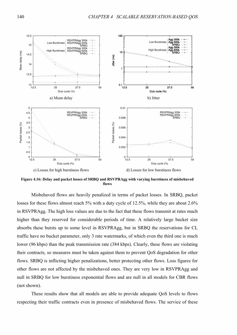
140 CHAPTER 4 SCALABLE RESERVATION-BASED QOS
Misbehaved flows are heavily penalized in terms of packet losses. In SRBQ, packet
losses for these flows almost reach 5% with a duty cycle of 12.5%, while they are about 2.6%
in RSVPRAgg. The high loss values are due to the fact that these flows transmit at rates much
higher than they reserved for considerable periods of time. A relatively large bucket size
absorbs these bursts up to some level in RSVPRAgg, but in SRBQ the reservations for CL
traffic have no bucket parameter, only 3 rate watermarks, of which even the third one is much
lower (96 kbps) than the peak transmission rate (384 kbps). Clearly, these flows are violating
their contracts, so measures must be taken against them to prevent QoS degradation for other
flows. SRBQ is inflicting higher penalizations, better protecting other flows. Loss figures for
other flows are not affected by the misbehaved ones. They are very low in RSVPRAgg and
null in SRBQ for low burstiness exponential flows and are null in all models for CBR flows
(not shown).
These results show that all models are able to provide adequate QoS levels to flows
respecting their traffic contracts even in presence of misbehaved flows. The service of these
13
13.5
14
14.5
15
15.5
12.5 25 37.5 50
Mean d
ela
y (
ms)
Duty cycle (%)
RSVPRAgg 300kRSVPRAgg 600k
SRBQRSVPRAgg 300kRSVPRAgg 600k
SRBQ
Low Burstiness
High Burstiness
0.1
1
10
100
50 37.5 25 12.5
Jitte
r (m
s)
Duty cycle (%)
Agg 300kAgg 600k
SRBQAgg 300kAgg 600k
SRBQ
0.1
1
10
100
50 37.5 25 12.5
Jitte
r (m
s)
Duty cycle (%)
Agg 300kAgg 600k
SRBQAgg 300kAgg 600k
SRBQ
Low Burstiness
High Burstiness
a) Mean delay b) Jitter
0
0.5
1
1.5
2
2.5
3
3.5
4
4.5
5
12.5 25 37.5 50
Packet lo
sses (
%)
Duty cycle (%)
RSVPRAgg 300kRSVPRAgg 600k
SRBQ
0
0.002
0.004
0.006
0.008
0.01
12.5 25 37.5 50
Packet lo
sses (
%)
Duty cycle (%)
RSVPRAgg 300kRSVPRAgg 600k
SRBQ
c) Losses for high burstiness flows d) Losses for low burstiness flows
Figure 4.16: Delay and packet losses of SRBQ and RSVPRAgg with varying burstiness of misbehaved
flows
4.5 CONCLUSIONS 141
flows is degraded in order to protect the well behaved flows: in SRBQ this degradation is only
in terms of packet losses; in RSVPRAgg they are less penalized in terms of losses, but also
have increased delay and jitter.
4.5 Conclusions
In this chapter we proposed and evaluated the Scalable Reservation-Based QoS
architecture, a QoS model where scalability is achieved by using exclusively low
computational complexity algorithms whose execution time is independent on the number of
simultaneous flows. SRBQ combines aggregate packet processing (classification, scheduling,
policing and shaping) with a scalable model of per-flow signaling-based resource reservation.
The underlying architecture is based on DiffServ: individual flows are aggregated into service
classes, mapped to DiffServ-compatible per-hop behaviors, and aggregate classification is
performed based on the DS field of the packet header. Two service classes are provided: the
Guaranteed Service class, with strict QoS guarantees, and a Controlled Load class, more
tolerant to burstiness. Some techniques were developed in order to ensure that per-flow
resource reservation signaling scales up to a very large number of simultaneous flows, namely
a label mechanism that provides routers with direct access to resource reservation information
of the flows, and an efficient implementation of soft state expiration timers.
Based on simulation results from our implementation of SRBQ in the ns-2 simulator,
we have analyzed the standard QoS parameters (delay, jitter and packet loss ratio) and the
per-class network resource utilization in different experiments, using both synthetic and real-
world multimedia streams. The results show that in spite of being based on aggregation,
SRBQ is able to support both strict (GS) and soft (CL) QoS guarantees, and provide adequate
isolation of in-profile flows from out-of-profile ones, much stronger in the GS class. Out-of-
profile CL flows are more penalized in terms of loss probability, while out-of-profile GS
flows are essentially penalized in terms of delay due to ingress shaping. The CL class is
appropriate for (eventually bursty) traffic which tolerates some packet loss. In fact, being
based on average rates, this class is much more tolerant to bursts, and, since there is no
shaping, no additional delays are inflicted to bursty flows. The GS class, on the other hand, is
ideal for flows intolerant to packet losses and having well defined traffic envelopes which
they do not exceed, but heavily penalizing for non-conformant flows.
The processing delay of reservation messages was also evaluated, in order to compute
the expected processor load it imposes. Although the results, obtained by measuring the
execution delay of the C++ method that processes SResv messages in the simulator code, were
142 CHAPTER 4 SCALABLE RESERVATION-BASED QOS
not entirely conclusive, we have enough reasons to believe that a real-world, optimized
implementation would be scalable enough to cope with the huge number of simultaneous
flows traversing a high-speed core router.
A comparative analysis of SRBQ against the RSVP Reservation Aggregation
architecture, proposed by the IETF as a scalable alternative to RSVP/IntServ that retains the
character of a signaling-based approach (as opposed to DiffServ), has shown that even though
both models are able to provide adequate QoS in a scalable way, most QoS results are
favorable to SRBQ and, more important, with SRBQ they are achieved with a much improved
usage of network resources.
143
CHAPTER 5
DAIDALOS APPROACH TO QUALITY OF SERVICE
In the previous chapters we have analyzed an existing scalable architecture for
providing QoS on IP internetworks and proposed a new one with improved characteristics.
Although based on the aggregation of individual flows, at least partially, both of these
architectures embody distributed models, where network elements along the data path
(routers) share the responsibility for ensuring that enough resources are available to the flows
for providing adequate QoS; there is no dedicated control element centralizing decisions or
actions. This design principle is consistent with the traditional, decentralized view of the
Internet, where a series of hierarchically flat network elements provide transport service for
data packets, in this case with QoS support as added value. The Internet, nevertheless, is
rapidly shifting away from this paradigm, and becoming the universal and unified
telecommunications infrastructure, providing communication services that go far beyond data
transport for which it was originally conceived. These services include those previously
supported by separate and dedicated infrastructures — telephony, broadcasting — and new,
previously inexistent ones — e.g., online gaming. Traditional telecom operators are migrating
to this new, converged platform and, as they shift to the Everything over IP (EoIP) paradigm,
they bring along some of their established practices, such as the use of out-of-band signaling
and of centralized equipment for processing signaling messages1 and keeping track of calls.
Therefore, a QoS architecture based on Bandwidth Brokers (or, more generally, on QoS
1 Quasi-associated signaling is the preferred mode in SS7 (Signaling System #7).
144 CHAPTER 5 DAIDALOS APPROACH TO QUALITY OF SERVICE
Brokers) is, understandably, more appealing to these new players. Centralized control entities
are easier to manage and have a lower cost, as the intelligence does not have to be replicated
on every router. Moreover, a Bandwidth Broker-based design provides an easier upgrade path,
as functionality may be added by changing only a few control entities, not the whole routing
infrastructure. A further advantage of the use of Bandwidth Brokers (BBs) is simplified
design, as centralized algorithms are usually simpler than their distributed counterparts. The
main drawback of BB-based architectures is the fact that BBs are single points of failure;
however, the potential resilience problem posed by single points of failure may be overcome
by other means, like the use of failover redundant BBs.
Another aspect in which the new and converged infrastructure differs from the legacy
Internet is the access. Traditional access through a wired Local Area Network (LAN) or via
modem has no support for mobility — there is a fixed link with constant characteristics
connecting terminal nodes to the network. However, the incorporation of a multitude of
wireless access technologies is gradually providing users with ubiquitous access to the
network, allowing them to move freely without disruption in the service, even though access
conditions may vary widely. This change implies that network topology may no longer be
considered flat, as the access links are clearly distinct in every aspect from the rest of the
infrastructure.
The second part of this thesis, consisting on chapters 5–8, describes work we
performed in the scope of phase 1 of the DAIDALOS project [Daidalos], mostly concerning
the QoS subsystem of the proposed network architecture. Our contributions include the high-
level design of this subsystem and the specification and analysis of some of its layers,
including resource management and signaling in the access, as well as inter-domain QoS
support. We have also worked on the optimization of session setup signaling in mobile
scenarios. In this chapter we introduce the DAIDALOS approach to QoS provisioning. We
begin with an overview of the project, its vision, goals and development model in section 5.1.
The QoS-related subset of the network architecture is described in section 5.3. Section 5.4
provides an overview of how end-to-end QoS control is achieved within DAIDALOS, and
section 5.5 introduces the different aspects of the network and problems that are dealt with in
the next chapters.
5.1 The DAIDALOS Project
Designing Advanced network Interfaces for the Delivery and Administration of
Location-independent, Optimized personal Services (DAIDALOS) is an EU-funded
5.1 THE DAIDALOS PROJECT 145
Integrated Project dedicated to the design of advanced network infrastructures and access
technologies for location-independent, personalized communication services. The
DAIDALOS vision is to seamlessly integrate heterogeneous network technologies in order to
achieve an open architecture based on a common IPv6 network protocol. Network operators
and service providers will be enabled to provide intelligent access combined with dynamic
service provisioning, supporting a wide range of voice, data and multimedia services. Several
business models and business process interactions are supported from an architectural point of
view. The new pervasive network and communication infrastructure developed by
DAIDALOS enables every user to benefit from customized communication services, such as
personalized newscasts tailored to their own individual preferences.
The design of the DAIDALOS architecture is based on five key concepts, which may
be summarized as follows:
• Mobility Management, AAA, Resource Management, QoS and Security (MARQS),
supporting functional integration for end-to-end services across heterogeneous
technologies
• Virtual Identity (VID), which separates the user from a device, thereby enables flexibility
as well as privacy and personalization
• Ubiquitous and Seamless Pervasiveness (USP), enabling pervasiveness across personal
and embedded devices, and allowing adaptation to changing contexts, movement and user
requests
• Seamless Integration of Broadcast (SIB), which integrates broadcast at both the
technology level, such as DVB-S/T-H, and at the services level, such TV, carousels and
datacast
• Federation, which allows network operators and service providers to offer and receive
services, allowing players to enter and leave the field in a dynamic business environment
Besides these five key concepts, there are two different, competing and cooperating,
development guidelines. The first one is user control: DAIDALOS acknowledges that the
future of telecommunications will ultimately empower the user with the choice of service
usage. Service delivery, however, is not a detail that should pertain to the user, and thus, the
second guideline is a bias towards telecoms, reflecting their vision of potentially realistic
scenarios for the telecommunications industry. Thus, most of the visions are associated with
the existence of large telecom operators as business entities on the process of service creation
and delivery.
146 CHAPTER 5 DAIDALOS APPROACH TO QUALITY OF SERVICE
A scenario-based design methodology has been chosen in the project — technical
requirements are derived from user-centric scenarios (real life descriptions of communication-
based activities). These scenarios are used in an iterative process of refining the requirements
for system and architecture design. Two major scenarios are used in this process. The first
one, “Mobile University”, involves foreign students having access to their personal set of
services and able to dynamically discover local services and devices. This scenario addresses
several aspects such as: the organization of everyday life at the university (friends,
appointments and reservations, classes, projects, exams, entertainment); locating people and
devices, checking availability, discovering local services; searching for the best and/or
cheapest available infrastructure; personal broadcasting (e.g., of classes and speeches). The
second one, the “Automotive” scenario, involves mobility-supporting services in and around
the vehicle, with aspects of personal multimedia, ad-hoc mobile networking and session
mobility. This scenario addresses aspects such as: access to personal information and services
inside and outside the vehicle; locating and detecting presence; service and content adaptation
based on QoS across network and operator boundaries; session mobility between terminals
(including vehicles), and across organizational and operational domains; broadcast services
for entertainment, inter-vehicle safety, and regional traffic information services. Together,
these scenarios are highly representative of a broad variety of education, entertainment and
business situations in the real mobile world.
Since DAIDALOS aims at the development of a network and service architecture, the
views of the telecom-operators currently deploying such architecture have to be considered.
The architecture has a set of characteristics coming from this background: flexibility, a
layered structure, optimization capabilities, and the possibility of being instantiated in
different business scenarios. Services may be produced at any point of the network — service
providers are not expected to be in specific locations in the network, though they are expected
to have specific business relationships with the transport operator, identifying the objective
contractual relationship expected between the two. However, DAIDALOS acknowledges that
several typical major players will still exist in the future (e.g., mobile telephony operators, TV
broadcasters), and has explicitly identified control elements for some of these players (notably
mobile operators, the potential core business). Overall, the direction of the architecture led to
the development of a universal, pervasive environment concept, with integrated
personalization as a keynote, conciliating users’ choices and operators’ interests.
The project is divided in five work packages, following a horizontal approach to the
system development. Three main work packages handle different aspects of the problem:
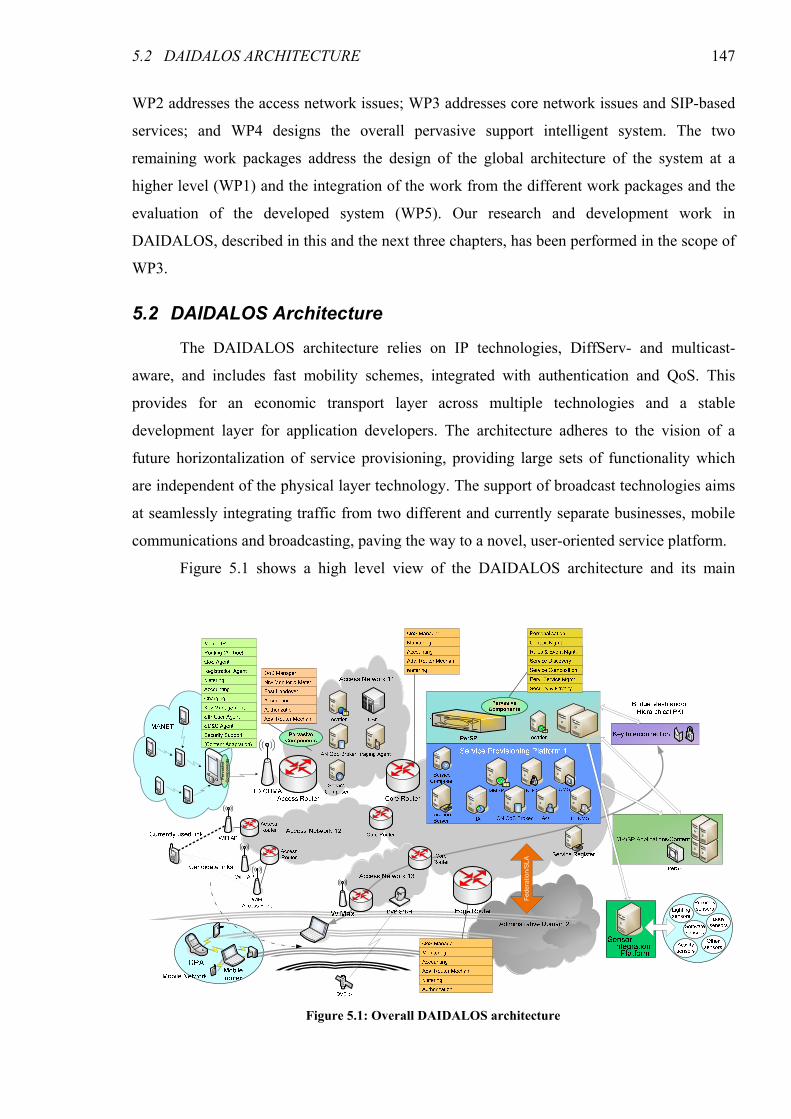
5.2 DAIDALOS ARCHITECTURE 147
WP2 addresses the access network issues; WP3 addresses core network issues and SIP-based
services; and WP4 designs the overall pervasive support intelligent system. The two
remaining work packages address the design of the global architecture of the system at a
higher level (WP1) and the integration of the work from the different work packages and the
evaluation of the developed system (WP5). Our research and development work in
DAIDALOS, described in this and the next three chapters, has been performed in the scope of
WP3.
5.2 DAIDALOS Architecture
The DAIDALOS architecture relies on IP technologies, DiffServ- and multicast-
aware, and includes fast mobility schemes, integrated with authentication and QoS. This
provides for an economic transport layer across multiple technologies and a stable
development layer for application developers. The architecture adheres to the vision of a
future horizontalization of service provisioning, providing large sets of functionality which
are independent of the physical layer technology. The support of broadcast technologies aims
at seamlessly integrating traffic from two different and currently separate businesses, mobile
communications and broadcasting, paving the way to a novel, user-oriented service platform.
Figure 5.1 shows a high level view of the DAIDALOS architecture and its main
Federation/SLA
Pervasive
Componen
ts
Figure 5.1: Overall DAIDALOS architecture
148 CHAPTER 5 DAIDALOS APPROACH TO QUALITY OF SERVICE
components. The architecture is quite complex, as it is expected to support virtually almost
any economically sensible telecommunications scenario and provide for economic
deployment of traditional communications scenarios. The figure mostly represents one
administrative domain. This domain may be federated (or have some sort of SLA established)
with other domains. The administrative domain is separated in core and access networks.
Three different access networks with wireless access are represented. Supported technologies
include WiFi, WiMax (even if no mobile standard exists, DAIDALOS is already integrating
this technology in its portfolio), TD-CDMA and overall Access Cells with DVB (both
Satellite and Terrestrial, though Daidalos has mostly focused on DVB-T).
Access Networks (ANs) are structured in cells. Each cell is controlled by an Access
Point (or a Base Station in some technologies), and an Access Router (AR) controls a set of
cells. DAIDALOS allows for the same AR to control several different APs for economic
reasons (both equipment cost and wireless performance).
Several components may be deployed in the AN. The AN QoS Broker performs
admission decisions and ensures Quality of Service. A Paging Controller allows power saving
in wireless environments. A Content Adaptation Node (CAN) may also be present to perform
multimedia codec adaptation whenever necessary.
Two other entities are deployed in the AN: a Service Composer, able to dynamically
compose the user-requested services, and a Location Controller, the physical support of
location — using diverse types of technologies, it provides the current location of the user to a
central location server. This is an aspect where privacy must be considered, and complex rules
may be in place regarding who can and who cannot access this information (part of the
DAIDALOS pervasive environment support). Note that Service Composer may need location
information for providing location-based services.
The architecture supports the use of Mobile Ad Hoc Networks (MANETs) for
extending the network coverage. Typically, at least one of the devices in the MANET will
also be connected to the access network, providing the others with access to the global
Internet and other operator services. Mobile Networks, where a series of devices and a Mobile
Router though which they are connected travel as a single entity2, are also supported. Even
though similarities exist between the MANET and Mobile Network concepts, there are
differences that imply different technology support.
2 Typically, this can be a car and the whole set of devices inside.
5.2 DAIDALOS ARCHITECTURE 149
On the core network, interconnected by routers, the operator holds a Service
Provisioning Platform. This platform provides a large set of functions required for the
efficient provision of telecommunication services:
• A Location Server, central repository for user location
• A Global Service Composer, providing the tools for long term service provision
• A Home Agent, for handling network layer movement of terminals
• A Key Distribution Center (KDC), providing the crypto information required for the A4C
operation; this entity will be interconnected to a global Public Key Infrastructure
• A CN QoS Broker to manage the core network transport infrastructure according to long
term statistics (this entity is different in nature from the AN QoS Broker, which focused
on admission control)
• A Multimedia Service Platform (MMSP), providing support for SIP-based services
• A Central Monitoring System (CMS) that collects information from probes in multiple
entities and acts as a central query service for real time monitoring information
• An A4C platform, centralizing functions related to Authentication, Authorization,
Auditing, Accounting and Charging
• A Policy-Based Network Management System (PBNMS)
The last five components are further described in the next section. Third party service
providers can be interconnected to the Service Provisioning Platform, providing value-added
services (notably content) on top of the base communication services.
Even though a global Pervasive Service Platform is represented in the SPP, it is not
the only entity that handles pervasiveness. Pervasiveness, the capability of providing
transparent service usage, is a complex function, achieved through the synergistic cooperation
of multiple entities. Pervasive components are distributed along all entities, from the mobile
terminal to the access router, into the SPP. These are all components that have degrees of
personalization and privacy. Their control can be achieved by different degrees of
intelligence. In DAIDALOS, the user has his service profile, containing rules that may be
quite complex and change as time goes by. The Pervasive Service Platform server is simply
the central rules engine in the network.
The Sensor Integration Platform collects information from sensors and provides that
information as a service to any entity requiring it. It is used, for example, to provide pervasive
and location-dependent services.
The architecture was defined in many aspects, even though explicit interface definition
was not a concern, given the research nature of the project. The innovation concerns different
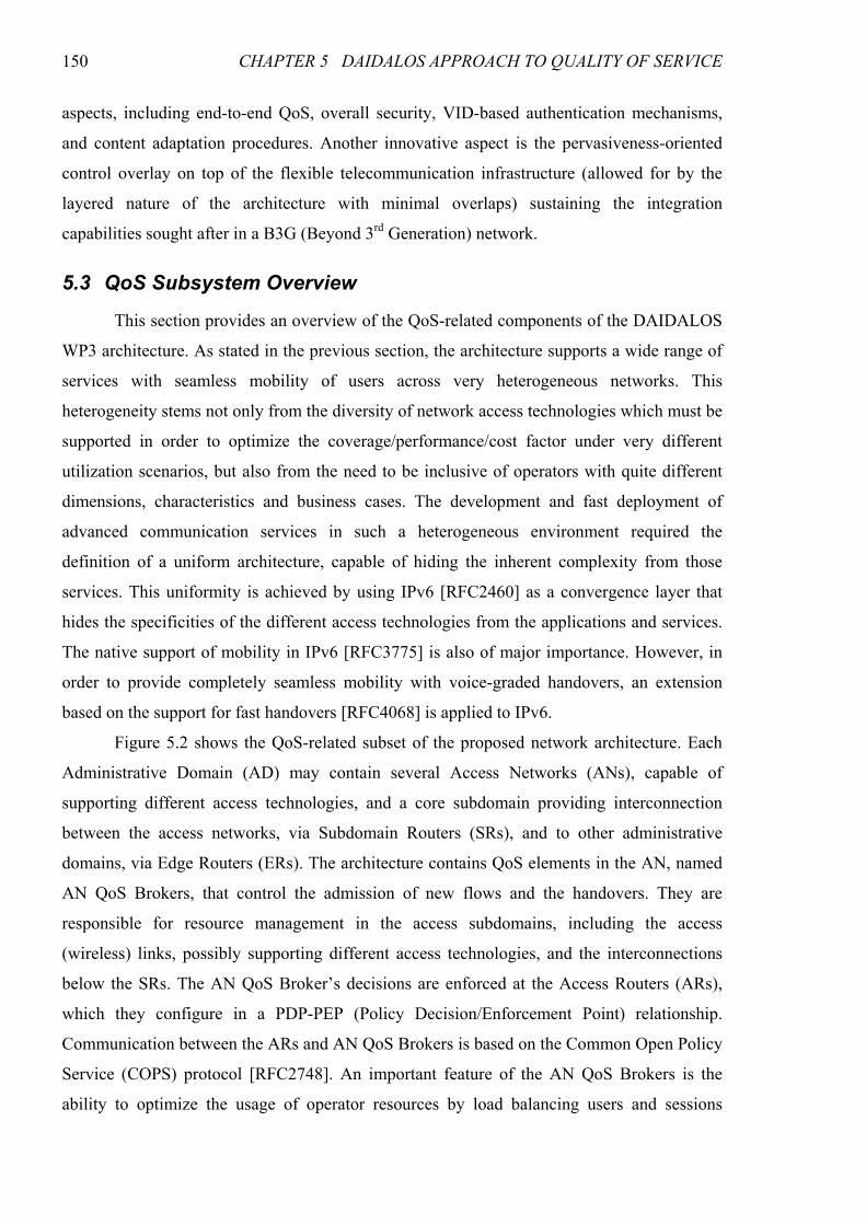
150 CHAPTER 5 DAIDALOS APPROACH TO QUALITY OF SERVICE
aspects, including end-to-end QoS, overall security, VID-based authentication mechanisms,
and content adaptation procedures. Another innovative aspect is the pervasiveness-oriented
control overlay on top of the flexible telecommunication infrastructure (allowed for by the
layered nature of the architecture with minimal overlaps) sustaining the integration
capabilities sought after in a B3G (Beyond 3rd Generation) network.
5.3 QoS Subsystem Overview
This section provides an overview of the QoS-related components of the DAIDALOS
WP3 architecture. As stated in the previous section, the architecture supports a wide range of
services with seamless mobility of users across very heterogeneous networks. This
heterogeneity stems not only from the diversity of network access technologies which must be
supported in order to optimize the coverage/performance/cost factor under very different
utilization scenarios, but also from the need to be inclusive of operators with quite different
dimensions, characteristics and business cases. The development and fast deployment of
advanced communication services in such a heterogeneous environment required the
definition of a uniform architecture, capable of hiding the inherent complexity from those
services. This uniformity is achieved by using IPv6 [RFC2460] as a convergence layer that
hides the specificities of the different access technologies from the applications and services.
The native support of mobility in IPv6 [RFC3775] is also of major importance. However, in
order to provide completely seamless mobility with voice-graded handovers, an extension
based on the support for fast handovers [RFC4068] is applied to IPv6.
Figure 5.2 shows the QoS-related subset of the proposed network architecture. Each
Administrative Domain (AD) may contain several Access Networks (ANs), capable of
supporting different access technologies, and a core subdomain providing interconnection
between the access networks, via Subdomain Routers (SRs), and to other administrative
domains, via Edge Routers (ERs). The architecture contains QoS elements in the AN, named
AN QoS Brokers, that control the admission of new flows and the handovers. They are
responsible for resource management in the access subdomains, including the access
(wireless) links, possibly supporting different access technologies, and the interconnections
below the SRs. The AN QoS Broker’s decisions are enforced at the Access Routers (ARs),
which they configure in a PDP-PEP (Policy Decision/Enforcement Point) relationship.
Communication between the ARs and AN QoS Brokers is based on the Common Open Policy
Service (COPS) protocol [RFC2748]. An important feature of the AN QoS Brokers is the
ability to optimize the usage of operator resources by load balancing users and sessions
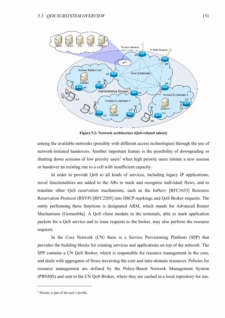
5.3 QOS SUBSYSTEM OVERVIEW 151
among the available networks (possibly with different access technologies) through the use of
network-initiated handovers. Another important feature is the possibility of downgrading or
shutting down sessions of low priority users3 when high priority users initiate a new session
or handover an existing one to a cell with insufficient capacity.
In order to provide QoS to all kinds of services, including legacy IP applications,
novel functionalities are added to the ARs to mark and recognize individual flows, and to
translate other QoS reservation mechanisms, such as the IntServ [RFC1633] Resource
Reservation Protocol (RSVP) [RFC2205] into DSCP markings and QoS Broker requests. The
entity performing these functions is designated ARM, which stands for Advanced Router
Mechanisms [Gomes04a]. A QoS client module in the terminals, able to mark application
packets for a QoS service and to issue requests to the broker, may also perform the resource
requests.
In the Core Network (CN) there is a Service Provisioning Platform (SPP) that
provides the building blocks for creating services and applications on top of the network. The
SPP contains a CN QoS Broker, which is responsible for resource management in the core,
and deals with aggregates of flows traversing the core and inter-domain resources. Policies for
resource management are defined by the Policy-Based Network Management System
(PBNMS) and sent to the CN QoS Broker, where they are cached in a local repository for use.
3 Priority is part of the user’s profile.
Figure 5.2: Network architecture (QoS-related subset)
152 CHAPTER 5 DAIDALOS APPROACH TO QUALITY OF SERVICE
The Central Monitoring System (CMS) collects statistics and network usage data from the
Network Monitoring Entities (NMEs), and configures these entities to perform both passive
and active probing. The information collected and processed by the CMS is fed to the
PBNMS and the QoS Brokers, which use it for proper network (re)configuration and resource
management. A Multimedia Service Platform (MMSP), consisting of a broker and proxy
servers, is responsible for the provision and control of multimedia services. It is also capable
of mapping application level QoS configurations to network resource requirements and of
performing QoS requests for the flows. This architecture, thus, has a large degree of flexibility
in QoS signaling, enabling the use of a diversity of QoS access signaling scenarios that fulfill
the needs of the different applications and business cases of different operators. Unification of
the scenarios is achieved by the centralization of admission and handover control at the AN
QoS Brokers.
An Authentication, Authorization, Accounting, Auditing and Charging (A4C) server is
also present in each domain. In order to improve the network efficiency and scalability, AN
QoS Brokers retrieve from the A4C a subset of the user profile when a user registers in the
network. This subset, termed Network View of the User Profile (NVUP), contains
information on the set of network level services (classes of service, bandwidth parameters)
that may be provided to the user, reflecting its contract with the operator. Similarly, a SVUP
(Service View of the User Profile), containing information on the higher level services
available to the user (e.g., voice calls, video telephony, and the respective codecs), is retrieved
by the MMSP to control multimedia services. The advantages of the NVUP and the SVUP are
twofold: on one hand, they speed up the resource reservation and service initiation processes,
as decisions are local to the AN QoS Broker or the MMSP, without need for communication
with the A4C; on the other hand, the load on the A4C servers, which are fundamental parts of
operator networks, is reduced.
QoS support in the core is based on the DiffServ model, for scalability reasons; in the
access, where (usually radio) resources are scarce, IntServ-like per-flow reservations are used
for better control. Even though resource management is performed on an aggregate basis in
the core and inter-domain segments of the path, information on the aggregates is propagated
to the AN QoS Brokers, where it is used for admission control in order to achieve end-to-end
QoS. This combination of per-flow and per-aggregate processing in a two-layer hierarchy
allows our architecture to provide fine-grained QoS control while keeping the scalability
properties of per-aggregate core resource management, decoupled from per-session signaling.
5.3 QOS SUBSYSTEM OVERVIEW 153
5.3.1 Comparison with UMTS
Compared to UMTS, the protocol stack in the DAIDALOS architecture is much
simplified: the IP layer is connected to the physical layer only through layer 2, contrary to
UMTS, which has a much more complex stack with multi-level encapsulation (please refer to
fig. 2.8 in page 155). Even though UMTS has the advantage that handover control is mostly
performed at the radio interface level, this strategy is not usable in heterogeneous networks4.
Moreover, the simpler DAIDALOS stack translates in less overhead, leading to lower
bandwidth consumption.
An important aspect in which the DAIDALOS architecture differs from UMTS is the
decoupling of the PDP functions (AN QoS Broker) from the MMSP; in UMTS both functions
are performed by the same element, the P-CSCF. Decoupling service level from network level
functions provides the flexibility for simultaneously supporting any required application
signaling protocol, freeing the architecture from being tied to a single protocol (SIP, in the
case of UMTS). The ability to support different application signaling protocols is an issue of
major importance, not only because there may be multiple application signaling protocols
requiring QoS (not necessarily related to multimedia), but also in order to make the
investment in infrastructure future-proof — the network infrastructure should be able to
provide support for a new protocol providing functions not possible to implement in SIP with
minimal changes. In the DAIDALOS architecture, supporting a new application signaling
protocol essentially requires adding QoS-aware proxies supporting the protocol, keeping the
rest of the network unchanged.
Probably the most important advantage of the DAIDALOS architecture over UMTS is
the support for heterogeneous access networks. The use of IPv6 protocol as a convergence
layer provides the network with independency on the underlying technologies and
significantly simplifies the support for mobility and QoS across heterogeneous networks,
“merely” requiring the mapping of IP QoS parameters into their layer 2 counterparts in order
to take maximal advantage of the QoS features provided by each technology. In contrast,
UMTS handovers are mostly performed at layer 2, without intervention of the IP entities. QoS
control during handovers is provided both in inter-Radio Network handovers and in inter-
SGSN handovers; in both cases, QoS levels are maintained, and no re-negotiation is
performed by the IMS entities — previously negotiated profiles are simply transferred from
the old path to the new one. This strategy cannot naturally be transposed to heterogeneous
4 In the future, the emerging IEEE 802.21 standard, currently in draft state, could change this state of affairs.
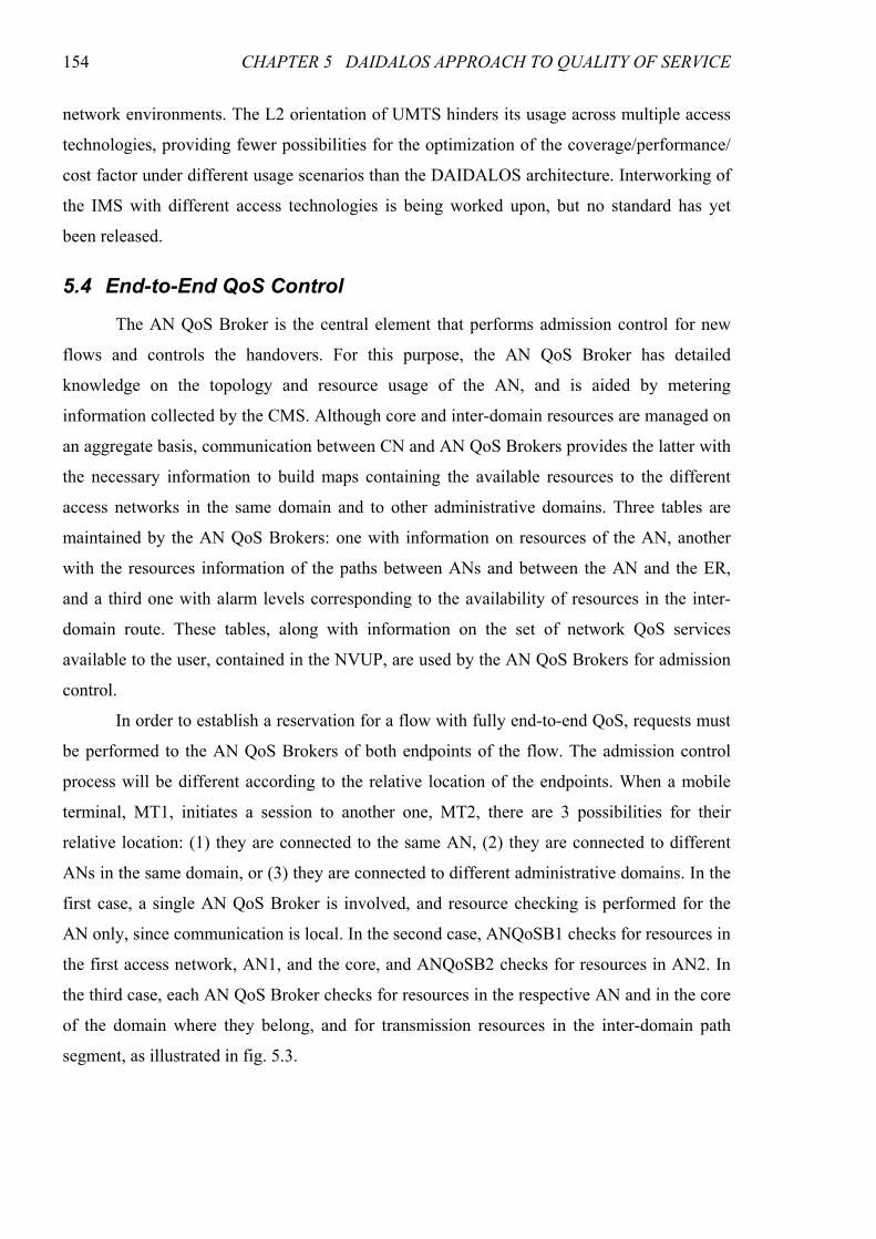
154 CHAPTER 5 DAIDALOS APPROACH TO QUALITY OF SERVICE
network environments. The L2 orientation of UMTS hinders its usage across multiple access
technologies, providing fewer possibilities for the optimization of the coverage/performance/
cost factor under different usage scenarios than the DAIDALOS architecture. Interworking of
the IMS with different access technologies is being worked upon, but no standard has yet
been released.
5.4 End-to-End QoS Control
The AN QoS Broker is the central element that performs admission control for new
flows and controls the handovers. For this purpose, the AN QoS Broker has detailed
knowledge on the topology and resource usage of the AN, and is aided by metering
information collected by the CMS. Although core and inter-domain resources are managed on
an aggregate basis, communication between CN and AN QoS Brokers provides the latter with
the necessary information to build maps containing the available resources to the different
access networks in the same domain and to other administrative domains. Three tables are
maintained by the AN QoS Brokers: one with information on resources of the AN, another
with the resources information of the paths between ANs and between the AN and the ER,
and a third one with alarm levels corresponding to the availability of resources in the inter-
domain route. These tables, along with information on the set of network QoS services
available to the user, contained in the NVUP, are used by the AN QoS Brokers for admission
control.
In order to establish a reservation for a flow with fully end-to-end QoS, requests must
be performed to the AN QoS Brokers of both endpoints of the flow. The admission control
process will be different according to the relative location of the endpoints. When a mobile
terminal, MT1, initiates a session to another one, MT2, there are 3 possibilities for their
relative location: (1) they are connected to the same AN, (2) they are connected to different
ANs in the same domain, or (3) they are connected to different administrative domains. In the
first case, a single AN QoS Broker is involved, and resource checking is performed for the
AN only, since communication is local. In the second case, ANQoSB1 checks for resources in
the first access network, AN1, and the core, and ANQoSB2 checks for resources in AN2. In
the third case, each AN QoS Broker checks for resources in the respective AN and in the core
of the domain where they belong, and for transmission resources in the inter-domain path
segment, as illustrated in fig. 5.3.
5.4 END-TO-END QOS CONTROL 155
5.4.1 Per-Flow QoS — Session Setup
As was previously mentioned, the DAIDALOS network architecture is very flexible
regarding the initiator of the QoS requests, which may be the MT, the ARM or the MMSP (or
even an application server). The necessity for such a flexible resource request model stems
from the need to support all the required applications, ranging from legacy, QoS-unaware data
transfer to advanced multimedia communication services with stringent QoS requirements, as
well as diverse deployment scenarios corresponding to different operator business cases. This
flexibility regarding the QoS request initiator led to the development of different scenarios for
the integration of application-level session setup signaling and network-level QoS signaling.
In the first scenario, suitable for SIP-based services, terminals perform only
application layer signaling. Based on the contents of application-level negotiation messages
(notably codec information) along with the user profile, the MMSP (or a SIP application
server) infers network level resource requirements and issues QoS Broker requests
accordingly. Communication between the MMSP and the AN QoS Broker is based on the
COPS protocol.
In the second scenario, the terminals themselves issue QoS Broker requests.
Applications use an Application Programming Interface (API) for requesting resources, which
gives them a much higher degree of control of received QoS. Contrary to the previous
scenario, this one supports non-SIP applications. However, both SIP and non-SIP applications
must be coded to use the API, disallowing the use of off-the-shelf applications without
modification. Since the terminals are not allowed to communicate directly with the QoS
Broker, mostly for security reasons, a QoS Attendant at the AR works as an intermediary.
Communication between the attendant and the QoS Broker is based on COPS, but a different
protocol is used between the terminal and the attendant (currently an RSVP derivative).
In the last scenario, application signaling (when it exists) or data packets (when it does
not) are intercepted by the ARM module at the AR. This module determines the amount of
resources to reserve for the session based on the type of application, the contents of
Figure 5.3: Admission control in the inter-domain call scenario
156 CHAPTER 5 DAIDALOS APPROACH TO QUALITY OF SERVICE
application layer signaling (if applicable) and the user’s NVUP, and issues the QoS Broker
requests. The main advantage of this scenario is the support of unmodified applications based
on standard or otherwise well-know protocols (and, to a lesser degree, of most non-standard
protocols); the drawbacks are less application control over QoS than in the MT scenario and
less powerful SIP services than in the MMSP scenario (since the ARM is not, and cannot be,
a fully-fledged SIP entity).
In spite of the differences, admission control and resource management is always
performed by the AN QoS Broker, thus unifying the signaling scenarios. A thorough
description and analysis of these scenarios is presented in the next chapter. The next two
sections, respectively, give an overview of the intra-domain (core) and inter-domain resource
management procedures that, combined with access resource management, provide end-to-
end QoS control capabilities to the architecture.
5.4.2 Intra-Domain QoS Control
The intra-domain QoS control covers QoS resource management for an administrative
domain from the user terminal to the edge router (ER). The main requirements for the intra-
domain QoS architecture are: 1) scalability of the signaling within the administrative domain;
2) flexibility (easy to manage); 3) efficiency in the usage of network resources; 4) support for
the mobility of users.
In this DiffServ environment, per-class aggregate resources are dynamically allocated,
by the CN QoS Broker, based on actual network traffic, operator polices and other conditions.
The monitoring subsystem plays an important role in this process, identifying aggregates
to/from where resources should be reassigned. Resource management in the core is based on:
• Policies received from the PBNMS — information containing the description of the
different transport services and the network topology. The CN QoS Broker has a bilateral
interface with PBNMS: it requests for policies at start-up time and receives unsolicited
policy definition when policies are changed in PBNMS. The CN QoS Broker generates
alarms to the PBNMS reporting, e.g., continuous resource over usage or AN QoS Broker
fault.
• Measurements supplied by the CMS — the CN QoS Broker detects if usage of a given
link is above a certain threshold and can reallocate resources from less used links in order
to increase the capacity of that link (upper part of fig. 5.4).
• Requests from the AN QoS Broker — AN QoS Broker can directly ask the CN QoS
Broker to change the amount of resources of a given link (lower part of fig. 5.4).
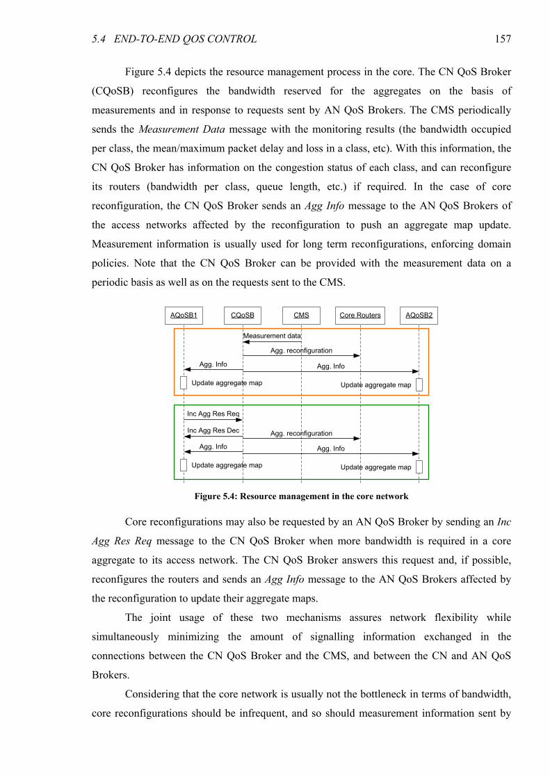
5.4 END-TO-END QOS CONTROL 157
Figure 5.4 depicts the resource management process in the core. The CN QoS Broker
(CQoSB) reconfigures the bandwidth reserved for the aggregates on the basis of
measurements and in response to requests sent by AN QoS Brokers. The CMS periodically
sends the Measurement Data message with the monitoring results (the bandwidth occupied
per class, the mean/maximum packet delay and loss in a class, etc). With this information, the
CN QoS Broker has information on the congestion status of each class, and can reconfigure
its routers (bandwidth per class, queue length, etc.) if required. In the case of core
reconfiguration, the CN QoS Broker sends an Agg Info message to the AN QoS Brokers of
the access networks affected by the reconfiguration to push an aggregate map update.
Measurement information is usually used for long term reconfigurations, enforcing domain
policies. Note that the CN QoS Broker can be provided with the measurement data on a
periodic basis as well as on the requests sent to the CMS.
Core reconfigurations may also be requested by an AN QoS Broker by sending an Inc
Agg Res Req message to the CN QoS Broker when more bandwidth is required in a core
aggregate to its access network. The CN QoS Broker answers this request and, if possible,
reconfigures the routers and sends an Agg Info message to the AN QoS Brokers affected by
the reconfiguration to update their aggregate maps.
The joint usage of these two mechanisms assures network flexibility while
simultaneously minimizing the amount of signalling information exchanged in the
connections between the CN QoS Broker and the CMS, and between the CN and AN QoS
Brokers.
Considering that the core network is usually not the bottleneck in terms of bandwidth,
core reconfigurations should be infrequent, and so should measurement information sent by
AQoSB1 CQoSB AQoSB2Core Routers
Update aggregate map
CMS
Measurement data
Agg. reconfiguration
Agg. InfoAgg. Info
Inc Agg Res Req
Inc Agg Res Dec Agg. reconfiguration
Agg. Info
Update aggregate map
Update aggregate map Update aggregate map
Agg. Info
Figure 5.4: Resource management in the core network
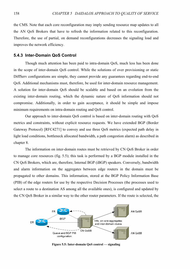
158 CHAPTER 5 DAIDALOS APPROACH TO QUALITY OF SERVICE
the CMS. Note that each core reconfiguration may imply sending resource map updates to all
the AN QoS Brokers that have to refresh the information related to this reconfiguration.
Therefore, the use of partial, on demand reconfigurations decreases the signaling load and
improves the network efficiency.
5.4.3 Inter-Domain QoS Control
Though much attention has been paid to intra-domain QoS, much less has been done
in the scope of inter-domain QoS control. While the solutions of over provisioning or static
DiffServ configurations are simple, they cannot provide any guarantees regarding end-to-end
QoS. Additional mechanisms must, therefore, be used for inter-domain resource management.
A solution for inter-domain QoS should be scalable and based on an evolution from the
existing inter-domain routing, which the dynamic nature of QoS information should not
compromise. Additionally, in order to gain acceptance, it should be simple and impose
minimum requirements on intra-domain routing and QoS control.
Our approach to inter-domain QoS control is based on inter-domain routing with QoS
metrics and constraints, without explicit resource requests. We have extended BGP (Border
Gateway Protocol) [RFC4271] to convey and use three QoS metrics (expected path delay in
light load conditions, bottleneck allocated bandwidth, a path congestion alarm) as described in
chapter 8.
The information on inter-domain routes must be retrieved by CN QoS Broker in order
to manage core resources (fig. 5.5); this task is performed by a BGP module installed in the
CN QoS Brokers, which are, therefore, Internal BGP (iBGP) speakers. Conversely, bandwidth
and alarm information on the aggregates between edge routers in the domain must be
propagated to other domains. This information, stored at the BGP Policy Information Base
(PIB) of the edge routers for use by the respective Decision Processes (the processes used to
select a route to a destination AS among all the available ones), is configured and updated by
the CN QoS Broker in a similar way to the other router parameters. If the route is selected, the
Figure 5.5: Inter-domain QoS control — signaling
5.5 SUMMARY 159
edge routers propagate it to their peers in the upstream domain with the updated QoS metrics.
As was previously mentioned, the CN QoS Broker propagates information on the inter-
domain routes to the AN QoS Brokers, where it is used for admission control purposes.
5.5 Summary
In this chapter we have introduced the DAIDALOS project, in scope of which we have
performed the work described in the second part of this thesis (chapters 5–8). We have
mentioned the five key concepts (MARQS, VID, USP, SIB and Federation) and the two
development guidelines (user control and telecom bias) that drive the project, as well as its
scenario-based development model. We have described the major goals of the project, and the
division of the research and development work into Work Packages that address the different
aspects of the telecommunication system to be developed. We have given an overview of the
QoS-related subset of the DAIDALOS WP3 architecture and how the relevant components
interact for providing communication services with end-to-end QoS support across
heterogeneous network access technologies. This overview will allow for a better
understanding of the next chapters, as the QoS-related subset of the architecture is the frame
of reference for the work therein presented. We have described the layered approach to
resource management, performed per-flow in the access and in an aggregate basis in the core
and inter-domain connections, and how the QoS information on the different layers and path
segments is combined in order to provide end-to-end QoS to the application flows.
The next three chapters will describe some problems we addressed in the scope of
DAIDALOS WP3 which, together with the collaboration in the definition of the architecture,
constitute most of our research and development work in the project. Chapter 6 deals with the
integration of application-level signaling and network-level resource reservation signaling, an
aspect closely related to the per-flow resource management performed at the access. We
describe our proposed signaling scenarios, which arise from the intrinsic flexibility of the
network in terms of the initiator of resource reservation, and discuss the coordination between
handover signaling and session QoS renegotiation signaling, of great importance in vertical
handovers. A comparative analysis of the scenarios is performed, based on simulation results,
addressing system behavior in normal operation and in overload conditions.
Chapter 7 addresses the inefficiency problems that arise from the joint use of SIP and
MIPv6, particularly when end-to-end resource reservation must be performed. We propose an
optimization based on cross-layer interactions and, again through simulation, demonstrate that
160 CHAPTER 5 DAIDALOS APPROACH TO QUALITY OF SERVICE
our proposal greatly reduces the setup delay of multimedia sessions with end-to-end QoS
support.
In chapter 8 we address the problem of inter-domain QoS routing, an integrating part
of our proposed solution to the problem of end-to-end QoS and resource management. We
propose a “black box” model based on virtual trunks, which may be regarded as traffic pipes
traversing transit domains and that, concatenated, form the end-to-end path for data flow
aggregates. The problem is formally stated and formulated in Integer Linear Programming
(ILP), allowing us to obtain the optimal set of routes for a given network configuration and
traffic matrix. A practical solution based on an extension of BGP using QoS metrics is
proposed. Through simulation results, we compare the performance of our proposed extension
with standard BGP, with the QoS_NLRI extension to BGP [Cristallo04] and with the optimal
route set provided by the ILP optimization.
161
CHAPTER 6
SESSION AND RESOURCE RESERVATION SIGNALING
As mentioned in the previous chapter, in order to support all the required applications
and operator business cases, the network architecture is very flexible regarding the initiator of
the QoS requests, which may be the Mobile Terminal (MT), the Advanced Router
Mechanisms (ARM), the Multimedia Service Proxy (MMSP), or even an application server.
This flexibility led to the development of different scenarios for the integration of application
setup and negotiation signaling and network QoS signaling, necessary for the establishment of
sessions with end-to-end QoS. The scenarios are unified by the centralization of admission
and handover control at the AN QoS Brokers.
In this chapter we present the different proposed signaling scenarios, illustrated by
Message Sequence Charts (MSCs) representing the initiation of a multimedia session between
two mobile terminals. Since the MT and ARM scenarios support legacy, non-QoS-aware data
applications, MSCs representing the initiation of this type of application are also provided for
these scenarios. We also discuss mobility issues, particularly the integration of session QoS
renegotiation with the handover signaling. The signaling scenarios are comparatively
analyzed, based on the results of several experiments performed in the ns-2 simulator, in
which we evaluated the efficiency of session setup under normal load and the system behavior
in overload conditions. This work was originally published in [Prior05a] and [Prior05c].
This chapter is organized as follows. The next section discusses session initiation in
the different signaling scenarios. Section 6.2 discusses mobility and QoS issues. A
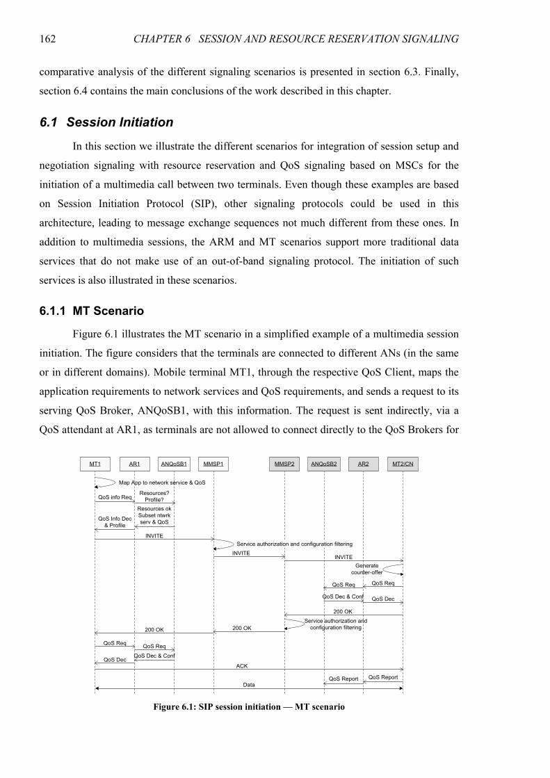
162 CHAPTER 6 SESSION AND RESOURCE RESERVATION SIGNALING
comparative analysis of the different signaling scenarios is presented in section 6.3. Finally,
section 6.4 contains the main conclusions of the work described in this chapter.
6.1 Session Initiation
In this section we illustrate the different scenarios for integration of session setup and
negotiation signaling with resource reservation and QoS signaling based on MSCs for the
initiation of a multimedia call between two terminals. Even though these examples are based
on Session Initiation Protocol (SIP), other signaling protocols could be used in this
architecture, leading to message exchange sequences not much different from these ones. In
addition to multimedia sessions, the ARM and MT scenarios support more traditional data
services that do not make use of an out-of-band signaling protocol. The initiation of such
services is also illustrated in these scenarios.
6.1.1 MT Scenario
Figure 6.1 illustrates the MT scenario in a simplified example of a multimedia session
initiation. The figure considers that the terminals are connected to different ANs (in the same
or in different domains). Mobile terminal MT1, through the respective QoS Client, maps the
application requirements to network services and QoS requirements, and sends a request to its
serving QoS Broker, ANQoSB1, with this information. The request is sent indirectly, via a
QoS attendant at AR1, as terminals are not allowed to connect directly to the QoS Brokers for
MT1 AR1 ANQoSB1 MMSP1 MMSP2 ANQoSB2 AR2 MT2/CN
Data
Map App to network service & QoS
Resources ok
Subset ntwrk
serv & QoSQoS Info Dec
& Profile
QoS ReportQoS Report
Service authorization and configuration filtering
QoS info ReqResources?
Profile?
INVITE
INVITEINVITE
QoS ReqQoS Req
QoS Dec & Conf
ACK
QoS Dec
200 OK
200 OK200 OK
QoS ReqQoS Req
QoS Dec & ConfQoS Dec
Generate
counter-offer
Service authorization and
configuration filtering
Figure 6.1: SIP session initiation — MT scenario
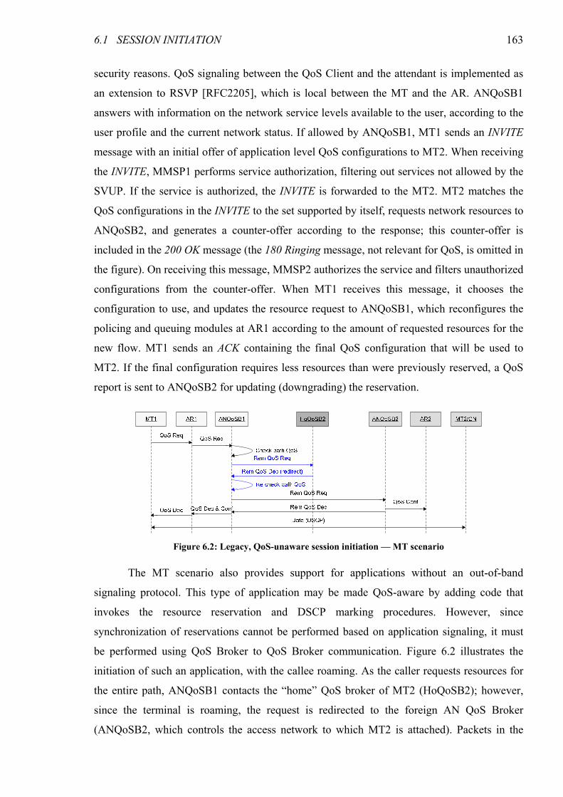
6.1 SESSION INITIATION 163
security reasons. QoS signaling between the QoS Client and the attendant is implemented as
an extension to RSVP [RFC2205], which is local between the MT and the AR. ANQoSB1
answers with information on the network service levels available to the user, according to the
user profile and the current network status. If allowed by ANQoSB1, MT1 sends an INVITE
message with an initial offer of application level QoS configurations to MT2. When receiving
the INVITE, MMSP1 performs service authorization, filtering out services not allowed by the
SVUP. If the service is authorized, the INVITE is forwarded to the MT2. MT2 matches the
QoS configurations in the INVITE to the set supported by itself, requests network resources to
ANQoSB2, and generates a counter-offer according to the response; this counter-offer is
included in the 200 OK message (the 180 Ringing message, not relevant for QoS, is omitted in
the figure). On receiving this message, MMSP2 authorizes the service and filters unauthorized
configurations from the counter-offer. When MT1 receives this message, it chooses the
configuration to use, and updates the resource request to ANQoSB1, which reconfigures the
policing and queuing modules at AR1 according to the amount of requested resources for the
new flow. MT1 sends an ACK containing the final QoS configuration that will be used to
MT2. If the final configuration requires less resources than were previously reserved, a QoS
report is sent to ANQoSB2 for updating (downgrading) the reservation.
The MT scenario also provides support for applications without an out-of-band
signaling protocol. This type of application may be made QoS-aware by adding code that
invokes the resource reservation and DSCP marking procedures. However, since
synchronization of reservations cannot be performed based on application signaling, it must
be performed using QoS Broker to QoS Broker communication. Figure 6.2 illustrates the
initiation of such an application, with the callee roaming. As the caller requests resources for
the entire path, ANQoSB1 contacts the “home” QoS broker of MT2 (HoQoSB2); however,
since the terminal is roaming, the request is redirected to the foreign AN QoS Broker
(ANQoSB2, which controls the access network to which MT2 is attached). Packets in the
Figure 6.2: Legacy, QoS-unaware session initiation — MT scenario
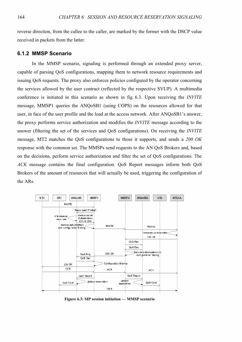
164 CHAPTER 6 SESSION AND RESOURCE RESERVATION SIGNALING
reverse direction, from the callee to the caller, are marked by the former with the DSCP value
received in packets from the latter.
6.1.2 MMSP Scenario
In the MMSP scenario, signaling is performed through an extended proxy server,
capable of parsing QoS configurations, mapping them to network resource requirements and
issuing QoS requests. The proxy also enforces policies configured by the operator concerning
the services allowed by the user contract (reflected by the respective SVUP). A multimedia
conference is initiated in this scenario as shown in fig. 6.3. Upon receiving the INVITE
message, MMSP1 queries the ANQoSB1 (using COPS) on the resources allowed for that
user, in face of the user profile and the load at the access network. After ANQoSB1’s answer,
the proxy performs service authorization and modifies the INVITE message according to the
answer (filtering the set of the services and QoS configurations). On receiving the INVITE
message, MT2 matches the QoS configurations to those it supports, and sends a 200 OK
response with the common set. The MMSPs send requests to the AN QoS Brokers and, based
on the decisions, perform service authorization and filter the set of QoS configurations. The
ACK message contains the final configuration. QoS Report messages inform both QoS
Brokers of the amount of resources that will actually be used, triggering the configuration of
the ARs.
Figure 6.3: SIP session initiation — MMSP scenario
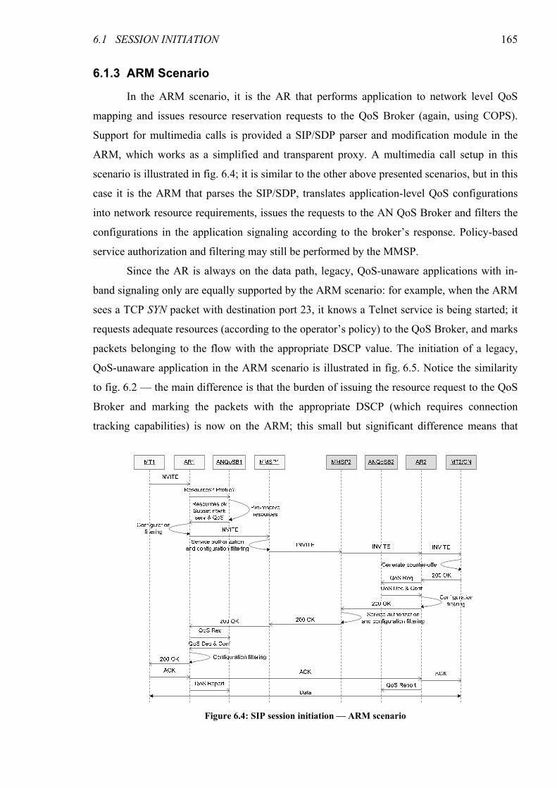
6.1 SESSION INITIATION 165
6.1.3 ARM Scenario
In the ARM scenario, it is the AR that performs application to network level QoS
mapping and issues resource reservation requests to the QoS Broker (again, using COPS).
Support for multimedia calls is provided a SIP/SDP parser and modification module in the
ARM, which works as a simplified and transparent proxy. A multimedia call setup in this
scenario is illustrated in fig. 6.4; it is similar to the other above presented scenarios, but in this
case it is the ARM that parses the SIP/SDP, translates application-level QoS configurations
into network resource requirements, issues the requests to the AN QoS Broker and filters the
configurations in the application signaling according to the broker’s response. Policy-based
service authorization and filtering may still be performed by the MMSP.
Since the AR is always on the data path, legacy, QoS-unaware applications with in-
band signaling only are equally supported by the ARM scenario: for example, when the ARM
sees a TCP SYN packet with destination port 23, it knows a Telnet service is being started; it
requests adequate resources (according to the operator’s policy) to the QoS Broker, and marks
packets belonging to the flow with the appropriate DSCP value. The initiation of a legacy,
QoS-unaware application in the ARM scenario is illustrated in fig. 6.5. Notice the similarity
to fig. 6.2 — the main difference is that the burden of issuing the resource request to the QoS
Broker and marking the packets with the appropriate DSCP (which requires connection
tracking capabilities) is now on the ARM; this small but significant difference means that
Figure 6.4: SIP session initiation — ARM scenario
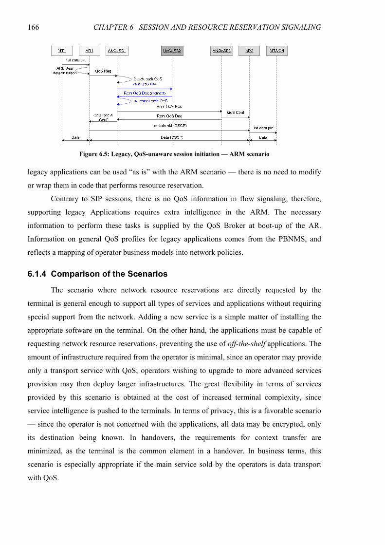
166 CHAPTER 6 SESSION AND RESOURCE RESERVATION SIGNALING
legacy applications can be used “as is” with the ARM scenario — there is no need to modify
or wrap them in code that performs resource reservation.
Contrary to SIP sessions, there is no QoS information in flow signaling; therefore,
supporting legacy Applications requires extra intelligence in the ARM. The necessary
information to perform these tasks is supplied by the QoS Broker at boot-up of the AR.
Information on general QoS profiles for legacy applications comes from the PBNMS, and
reflects a mapping of operator business models into network policies.
6.1.4 Comparison of the Scenarios
The scenario where network resource reservations are directly requested by the
terminal is general enough to support all types of services and applications without requiring
special support from the network. Adding a new service is a simple matter of installing the
appropriate software on the terminal. On the other hand, the applications must be capable of
requesting network resource reservations, preventing the use of off-the-shelf applications. The
amount of infrastructure required from the operator is minimal, since an operator may provide
only a transport service with QoS; operators wishing to upgrade to more advanced services
provision may then deploy larger infrastructures. The great flexibility in terms of services
provided by this scenario is obtained at the cost of increased terminal complexity, since
service intelligence is pushed to the terminals. In terms of privacy, this is a favorable scenario
— since the operator is not concerned with the applications, all data may be encrypted, only
its destination being known. In handovers, the requirements for context transfer are
minimized, as the terminal is the common element in a handover. In business terms, this
scenario is especially appropriate if the main service sold by the operators is data transport
with QoS.
Figure 6.5: Legacy, QoS-unaware session initiation — ARM scenario
6.1 SESSION INITIATION 167
The scenario where the MMSP controls resource reservations is only appropriate for
SIP applications1. While many other services, including legacy data transfer services such as
FTP, could, in principle, be wrapped in SIP, it is unnatural and cumbersome to do so, adding
unnecessary complexity to the terminals and defeating one advantage of this scenario, the
simplification of the terminal by performing only application level signaling. For multimedia
services, the proxies actively limit the set of QoS configurations inside the application
signaling to those allowed by the user profile and for which network resources are available,
improving the efficiency of session setup and negotiation. Moreover, with this approach,
current and future SIP-based applications may be used with minimal or no need for
modifications. The MMSP is a fundamental piece in this scenario, and the network operator
itself must deploy it in order to have the complete control over the network and signaling.
Very similar, in terms of signaling, to the MMSP scenario is the scenario where application
servers perform resource reservations. However, two different providers may be involved in
this case: the network operator, providing transport, and the service operator, providing
content or a value-added service. A trust (federation) relationship between the two is required,
since the application server needs to be able to issue requests to the QoS broker. Service- and
content-based charging are easily provided by this model. This approach is efficient for
multimedia streaming, file downloading, and all types of applications using central servers,
since the servers have good knowledge of the service requirements in terms of network
resources. The application providers may deliver content to the user with QoS even if the
application itself is QoS-unaware, lowering the requirements on the terminals. Privacy is
better handled in this scenario, as the network operator needs not be aware of the retrieved
content. Multimedia conference and some other user-to-user services, not necessarily based
on SIP, may as well be supported by the application servers.
In the ARM scenario, complexity is pushed to the network edge. Even though
scalability in the MMSP may be achieved by load balancing among a number of different
servers, a solution where the signaling parsing and reservation initiating entity is as close as
possible to the terminals is naturally scalable without special needs for load balancing, since a
smaller number of terminals will request its services. Although not as scalable as the MT
scenario, it allows the use of simple terminals incapable of performing QoS requests.
Regarding signaling complexity, since the AR is naturally in the signaling path, acting as
Policy Enforcement Point (PEP) at transport level, less signaling is required in this scenario.
1 Conceptually, other protocols, such as H.323, could as well be supported, provided that a functional equivalent of the QoS-
enabled SIP Proxy (the Gatekeeper in H.323, for example), enhanced with DAIDALOS-specific modules, were deployed.
168 CHAPTER 6 SESSION AND RESOURCE RESERVATION SIGNALING
With the ARM, QoS for legacy applications is easily supported without modifying them or
requiring middleware in the terminal, and adding support for another application signaling
protocol requires only a software update to the AR (push of a new application translation
module). In terms of application support, this model is as flexible as the first: since the ARM
is capable of trans-signaling [Gomes04a], minimum support can be provided even for
applications with no corresponding ARM module, provided they are QoS-aware. Overall, this
is the most flexible scenario, since it provides a choice between dumber terminals using only
the limited set of well-known services supported by the ARM and more intelligent and costly
terminals that support any application. Both service- and transport-based charging are easily
supported. The ARM, however, needs to maintain some state machine consistency with the
application signaling, and signaling messages cannot be encrypted, as they may be processed
by the ARM. This scenario is preferred when a set of simple well-known services must be
universally supported.
6.2 Mobility
Mobility plays a central role in 4G networks, and the requirement for seamless
handovers is probably the most demanding one in terms of timing. In a heterogeneous
network, handovers may be performed between different access technologies; therefore, in the
DAIDALOS architecture they are performed at the access-agnostic layer 3. The handover
process in this architecture is extended from the fast handover mechanism defined in
[RFC4068], associated with the Candidate Access Router Discovery (CARD) protocol
[RFC4066], used to propagate information on prospective networks for handover to the MT.
The amount of available resources may vary widely in a vertical (inter-technology) handover.
In order to fully exploit the resources provided by the different access technologies, the
architecture provides support for the coordination between handover and application
signaling, allowing for session renegotiation at handover time. This is achieved by including
information that session renegotiation is necessary (or advisable) in one of the handover
messages, which is used as a trigger for application-level session renegotiation, as will be
described below.
Figure 6.6 illustrates a basic user-initiated, intra-domain, inter-AN handover process
(procedures specific to inter-technology handovers are discussed later in this section). The
terminal begins by sending a Router Solicitation for Proxy (RtSolPr) message with an
indication of the new network where to perform the handover, selected based on information
previously provided by CARD. The old AR (oAR1) sends a handover request message to the
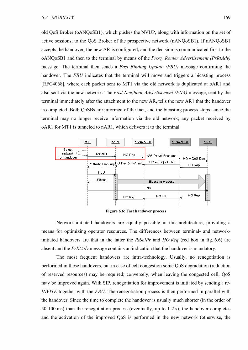
6.2 MOBILITY 169
old QoS Broker (oANQoSB1), which pushes the NVUP, along with information on the set of
active sessions, to the QoS Broker of the prospective network (nANQoSB1). If nANQoSB1
accepts the handover, the new AR is configured, and the decision is communicated first to the
oANQoSB1 and then to the terminal by means of the Proxy Router Advertisement (PrRtAdv)
message. The terminal then sends a Fast Binding Update (FBU) message confirming the
handover. The FBU indicates that the terminal will move and triggers a bicasting process
[RFC4068], where each packet sent to MT1 via the old network is duplicated at oAR1 and
also sent via the new network. The Fast Neighbor Advertisement (FNA) message, sent by the
terminal immediately after the attachment to the new AR, tells the new AR1 that the handover
is completed. Both QoSBs are informed of the fact, and the bicasting process stops, since the
terminal may no longer receive information via the old network; any packet received by
oAR1 for MT1 is tunneled to nAR1, which delivers it to the terminal.
Network-initiated handovers are equally possible in this architecture, providing a
means for optimizing operator resources. The differences between terminal- and network-
initiated handovers are that in the latter the RtSolPr and HO Req (red box in fig. 6.6) are
absent and the PrRtAdv message contains an indication that the handover is mandatory.
The most frequent handovers are intra-technology. Usually, no renegotiation is
performed in these handovers, but in case of cell congestion some QoS degradation (reduction
of reserved resources) may be required; conversely, when leaving the congested cell, QoS
may be improved again. With SIP, renegotiation for improvement is initiated by sending a re-
INVITE together with the FBU. The renegotiation process is then performed in parallel with
the handover. Since the time to complete the handover is usually much shorter (in the order of
50-100 ms) than the renegotiation process (eventually, up to 1-2 s), the handover completes
and the activation of the improved QoS is performed in the new network (otherwise, the
Figure 6.6: Fast handover process
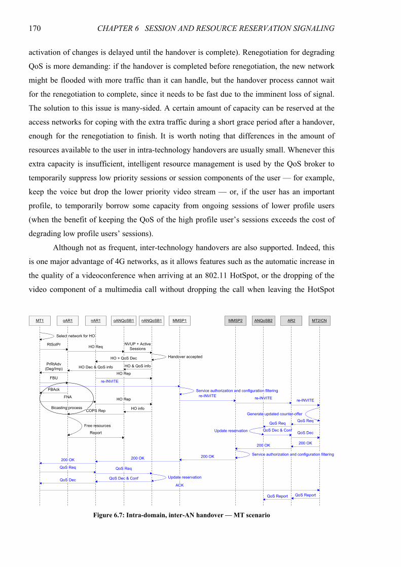
170 CHAPTER 6 SESSION AND RESOURCE RESERVATION SIGNALING
activation of changes is delayed until the handover is complete). Renegotiation for degrading
QoS is more demanding: if the handover is completed before renegotiation, the new network
might be flooded with more traffic than it can handle, but the handover process cannot wait
for the renegotiation to complete, since it needs to be fast due to the imminent loss of signal.
The solution to this issue is many-sided. A certain amount of capacity can be reserved at the
access networks for coping with the extra traffic during a short grace period after a handover,
enough for the renegotiation to finish. It is worth noting that differences in the amount of
resources available to the user in intra-technology handovers are usually small. Whenever this
extra capacity is insufficient, intelligent resource management is used by the QoS broker to
temporarily suppress low priority sessions or session components of the user — for example,
keep the voice but drop the lower priority video stream — or, if the user has an important
profile, to temporarily borrow some capacity from ongoing sessions of lower profile users
(when the benefit of keeping the QoS of the high profile user’s sessions exceeds the cost of
degrading low profile users’ sessions).
Although not as frequent, inter-technology handovers are also supported. Indeed, this
is one major advantage of 4G networks, as it allows features such as the automatic increase in
the quality of a videoconference when arriving at an 802.11 HotSpot, or the dropping of the
video component of a multimedia call without dropping the call when leaving the HotSpot
Bicasting process
MT1 oAR1 oANQoSB1 MMSP1 MMSP2 ANQoSB2 AR2 MT2/CNnAR1 nANQoSB1
RtSolPr
FBU
FBAck
FNA
HO + QoS Dec
HO Req
HO Dec & QoS info HO & QoS info
re-INVITE
re-INVITEre-INVITE
re-INVITE
QoS Req
QoS Dec & Conf
200 OK200 OK
200 OK200 OK
QoS Dec & Conf
QoS Req
ACK
ReportUpdate reservation
Update reservation
Free resources
Select network for HO
Handover accepted
HO Rep
HO Rep
HO infoCOPS Rep
QoS Req
QoS Dec
QoS Req
QoS Dec
Service authorization and configuration filtering
Service authorization and configuration filtering
QoS ReportQoS Report
200 OK
Generate updated counter-offer
NVUP + Active
Sessions
PrRtAdv
(Deg/Imp)
Figure 6.7: Intra-domain, inter-AN handover — MT scenario
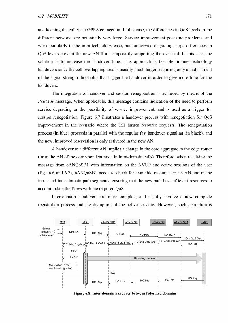
6.2 MOBILITY 171
and keeping the call via a GPRS connection. In this case, the differences in QoS levels in the
different networks are potentially very large. Service improvement poses no problems, and
works similarly to the intra-technology case, but for service degrading, large differences in
QoS levels prevent the new AN from temporarily supporting the overload. In this case, the
solution is to increase the handover time. This approach is feasible in inter-technology
handovers since the cell overlapping area is usually much larger, requiring only an adjustment
of the signal strength thresholds that trigger the handover in order to give more time for the
handovers.
The integration of handover and session renegotiation is achieved by means of the
PrRtAdv message. When applicable, this message contains indication of the need to perform
service degrading or the possibility of service improvement, and is used as a trigger for
session renegotiation. Figure 6.7 illustrates a handover process with renegotiation for QoS
improvement in the scenario where the MT issues resource requests. The renegotiation
process (in blue) proceeds in parallel with the regular fast handover signaling (in black), and
the new, improved reservation is only activated in the new AN.
A handover to a different AN implies a change in the core aggregate to the edge router
(or to the AN of the correspondent node in intra-domain calls). Therefore, when receiving the
message from oANQoSB1 with information on the NVUP and active sessions of the user
(figs. 6.6 and 6.7), nANQoSB1 needs to check for available resources in its AN and in the
intra- and inter-domain path segments, ensuring that the new path has sufficient resources to
accommodate the flows with the required QoS.
Inter-domain handovers are more complex, and usually involve a new complete
registration process and the disruption of the active sessions. However, such disruption is
MT1 oAR1 oANQoSB1 nAR1nANQoSB1
PrRtAdv, Deg/ImpHO Dec & QoS info
Select
network
for handover
Bicasting process
RtSolPrHO Req*HO Req
HO RepHO and QoS info
HO + QoS Dec
FBAck
FBU
FNA
HO infoHO Rep
HO Rep
oCNQoSB nCNQoSB
HO info HO info
HO and QoS info HO and QoS info
HO Req* HO Req*
Registration in the
new domain (partial)
Figure 6.8: Inter-domain handover between federated domains
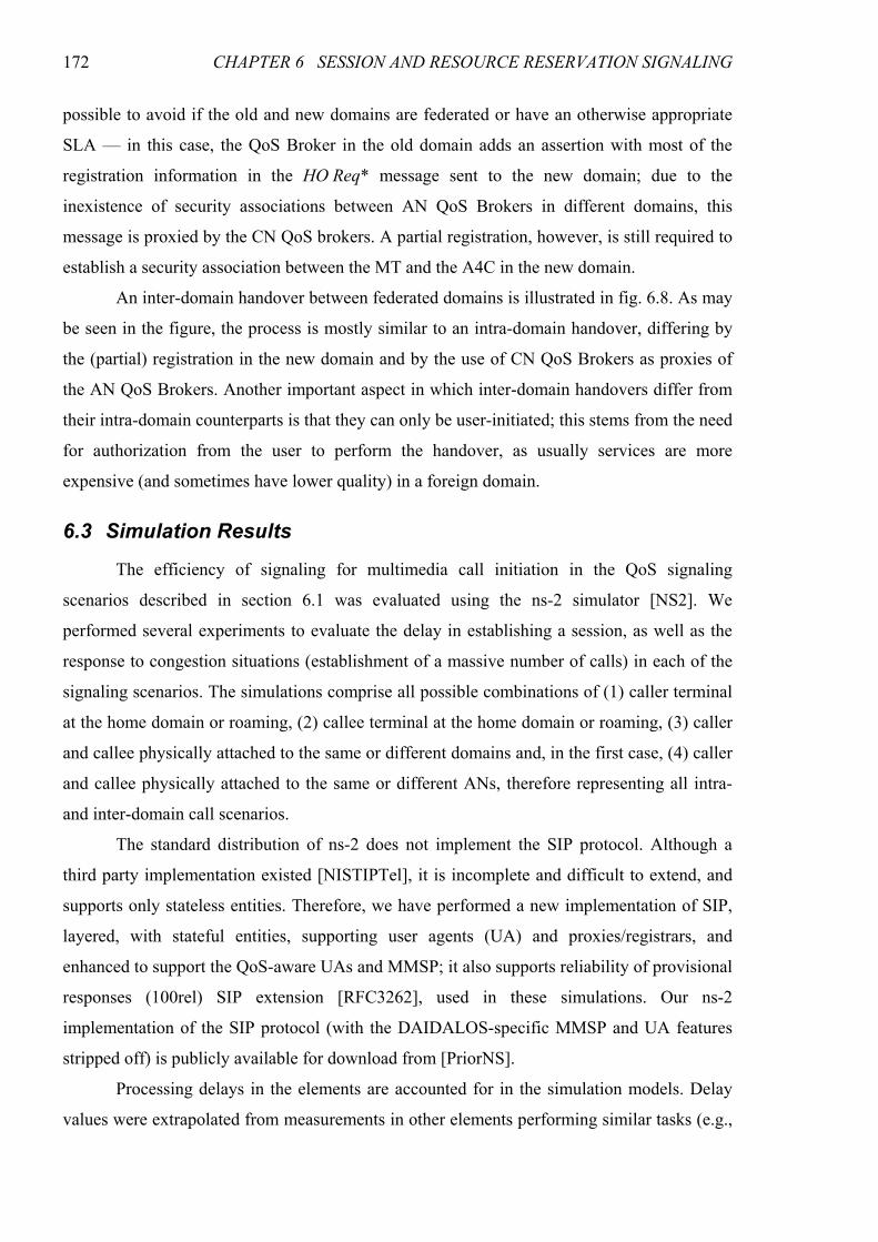
172 CHAPTER 6 SESSION AND RESOURCE RESERVATION SIGNALING
possible to avoid if the old and new domains are federated or have an otherwise appropriate
SLA — in this case, the QoS Broker in the old domain adds an assertion with most of the
registration information in the HO Req* message sent to the new domain; due to the
inexistence of security associations between AN QoS Brokers in different domains, this
message is proxied by the CN QoS brokers. A partial registration, however, is still required to
establish a security association between the MT and the A4C in the new domain.
An inter-domain handover between federated domains is illustrated in fig. 6.8. As may
be seen in the figure, the process is mostly similar to an intra-domain handover, differing by
the (partial) registration in the new domain and by the use of CN QoS Brokers as proxies of
the AN QoS Brokers. Another important aspect in which inter-domain handovers differ from
their intra-domain counterparts is that they can only be user-initiated; this stems from the need
for authorization from the user to perform the handover, as usually services are more
expensive (and sometimes have lower quality) in a foreign domain.
6.3 Simulation Results
The efficiency of signaling for multimedia call initiation in the QoS signaling
scenarios described in section 6.1 was evaluated using the ns-2 simulator [NS2]. We
performed several experiments to evaluate the delay in establishing a session, as well as the
response to congestion situations (establishment of a massive number of calls) in each of the
signaling scenarios. The simulations comprise all possible combinations of (1) caller terminal
at the home domain or roaming, (2) callee terminal at the home domain or roaming, (3) caller
and callee physically attached to the same or different domains and, in the first case, (4) caller
and callee physically attached to the same or different ANs, therefore representing all intra-
and inter-domain call scenarios.
The standard distribution of ns-2 does not implement the SIP protocol. Although a
third party implementation existed [NISTIPTel], it is incomplete and difficult to extend, and
supports only stateless entities. Therefore, we have performed a new implementation of SIP,
layered, with stateful entities, supporting user agents (UA) and proxies/registrars, and
enhanced to support the QoS-aware UAs and MMSP; it also supports reliability of provisional
responses (100rel) SIP extension [RFC3262], used in these simulations. Our ns-2
implementation of the SIP protocol (with the DAIDALOS-specific MMSP and UA features
stripped off) is publicly available for download from [PriorNS].
Processing delays in the elements are accounted for in the simulation models. Delay
values were extrapolated from measurements in other elements performing similar tasks (e.g.,
6.3 SIMULATION RESULTS 173
MMSP delays were extrapolated from measurements on SIP proxies). Message processing is
performed in a FIFO fashion, meaning that processing of each message can only begin after
all previous messages have been processed. Each message type takes a fixed amount of time
to process, which is different for the different message types. Processing delays for SIP
messages were simulated at both the MT (10 ms) and the MMSP (0.8 ms), with an increment
for messages with SDP bodies (10 ms in the MT and 0.8 ms in the MMSP); this increment is
larger when the entity performs QoS Broker requests (15 ms in the MT and 1ms in the
MMSP). At the ARM, processing delay is considered for SIP messages with SDP bodies
(0.2 ms), much larger in the ARM scenario (1 ms). AN QoS Broker request processing is also
accounted for (1 ms). The remaining processing delays are considered negligible when
compared to these, and ignored in the simulations.
a) Call accepted
b) Call rejected at the caller side (upper) or the callee side (lower)
Figure 6.9: Simulated message sequences — MMSP scenario
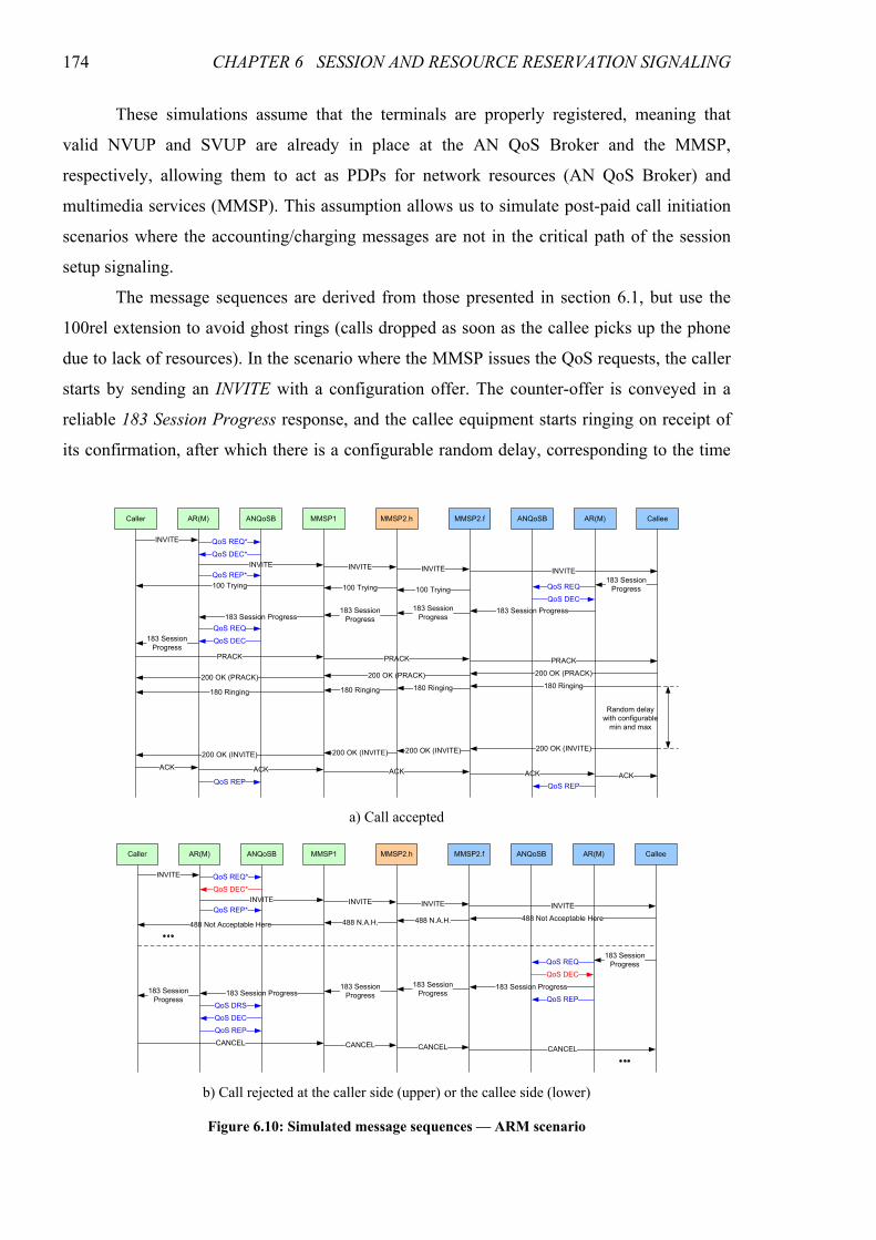
174 CHAPTER 6 SESSION AND RESOURCE RESERVATION SIGNALING
These simulations assume that the terminals are properly registered, meaning that
valid NVUP and SVUP are already in place at the AN QoS Broker and the MMSP,
respectively, allowing them to act as PDPs for network resources (AN QoS Broker) and
multimedia services (MMSP). This assumption allows us to simulate post-paid call initiation
scenarios where the accounting/charging messages are not in the critical path of the session
setup signaling.
The message sequences are derived from those presented in section 6.1, but use the
100rel extension to avoid ghost rings (calls dropped as soon as the callee picks up the phone
due to lack of resources). In the scenario where the MMSP issues the QoS requests, the caller
starts by sending an INVITE with a configuration offer. The counter-offer is conveyed in a
reliable 183 Session Progress response, and the callee equipment starts ringing on receipt of
its confirmation, after which there is a configurable random delay, corresponding to the time
INVITE
183 Session
Progress
PRACK
Caller Callee
200 OK (PRACK)
180 Ringing
Random delay
with configurable
min and max
200 OK (INVITE)
ACK
AR(M) AR(M)
QoS DEC
ANQoSB MMSP1
QoS REQ
QoS REP
QoS REQ
QoS DEC
QoS DEC*
QoS REP*
QoS REQ*
INVITE
183 Session Progress
183 Session
Progress
ACK
QoS REP
MMSP2.f ANQoSBMMSP2.h
INVITE INVITE INVITE
183 Session
Progress183 Session
Progress183 Session Progress
PRACK PRACK
200 OK (PRACK)200 OK (PRACK)
180 Ringing180 Ringing180 Ringing
ACK ACK ACK
200 OK (INVITE)200 OK (INVITE)200 OK (INVITE)
100 Trying 100 Trying 100 Trying
a) Call accepted
INVITE
488 Not Acceptable Here
Caller CalleeAR(M) AR(M)ANQoSB MMSP1
QoS DEC*
QoS REP*
QoS REQ*
INVITE
MMSP2.f ANQoSBMMSP2.h
INVITE INVITE INVITE
488 N.A.H.488 N.A.H.488 Not Acceptable Here
183 Session
ProgressQoS REQ
QoS DEC
183 Session Progress183 Session
Progress
183 Session
Progress183 Session
Progress183 Session ProgressQoS REP
CANCEL CANCEL CANCEL CANCEL
QoS DEC
QoS DRS
QoS REP
b) Call rejected at the caller side (upper) or the callee side (lower)
Figure 6.10: Simulated message sequences — ARM scenario
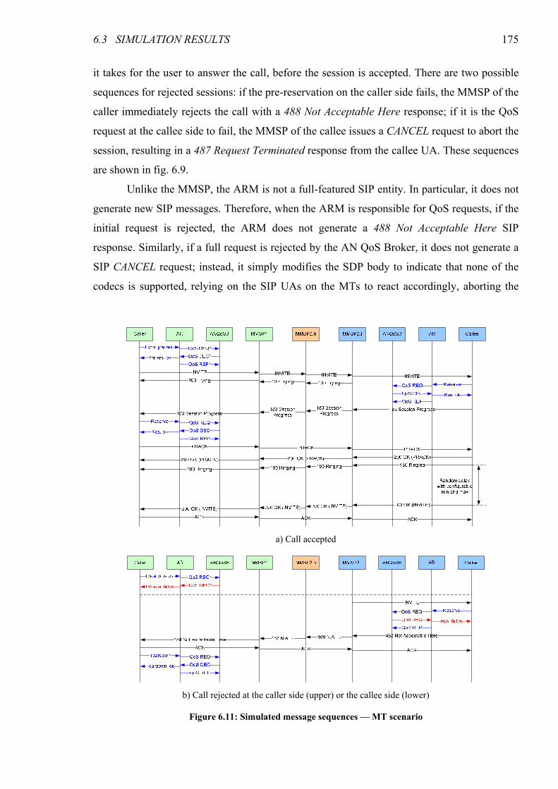
6.3 SIMULATION RESULTS 175
it takes for the user to answer the call, before the session is accepted. There are two possible
sequences for rejected sessions: if the pre-reservation on the caller side fails, the MMSP of the
caller immediately rejects the call with a 488 Not Acceptable Here response; if it is the QoS
request at the callee side to fail, the MMSP of the callee issues a CANCEL request to abort the
session, resulting in a 487 Request Terminated response from the callee UA. These sequences
are shown in fig. 6.9.
Unlike the MMSP, the ARM is not a full-featured SIP entity. In particular, it does not
generate new SIP messages. Therefore, when the ARM is responsible for QoS requests, if the
initial request is rejected, the ARM does not generate a 488 Not Acceptable Here SIP
response. Similarly, if a full request is rejected by the AN QoS Broker, it does not generate a
SIP CANCEL request; instead, it simply modifies the SDP body to indicate that none of the
codecs is supported, relying on the SIP UAs on the MTs to react accordingly, aborting the
a) Call accepted
b) Call rejected at the caller side (upper) or the callee side (lower)
Figure 6.11: Simulated message sequences — MT scenario
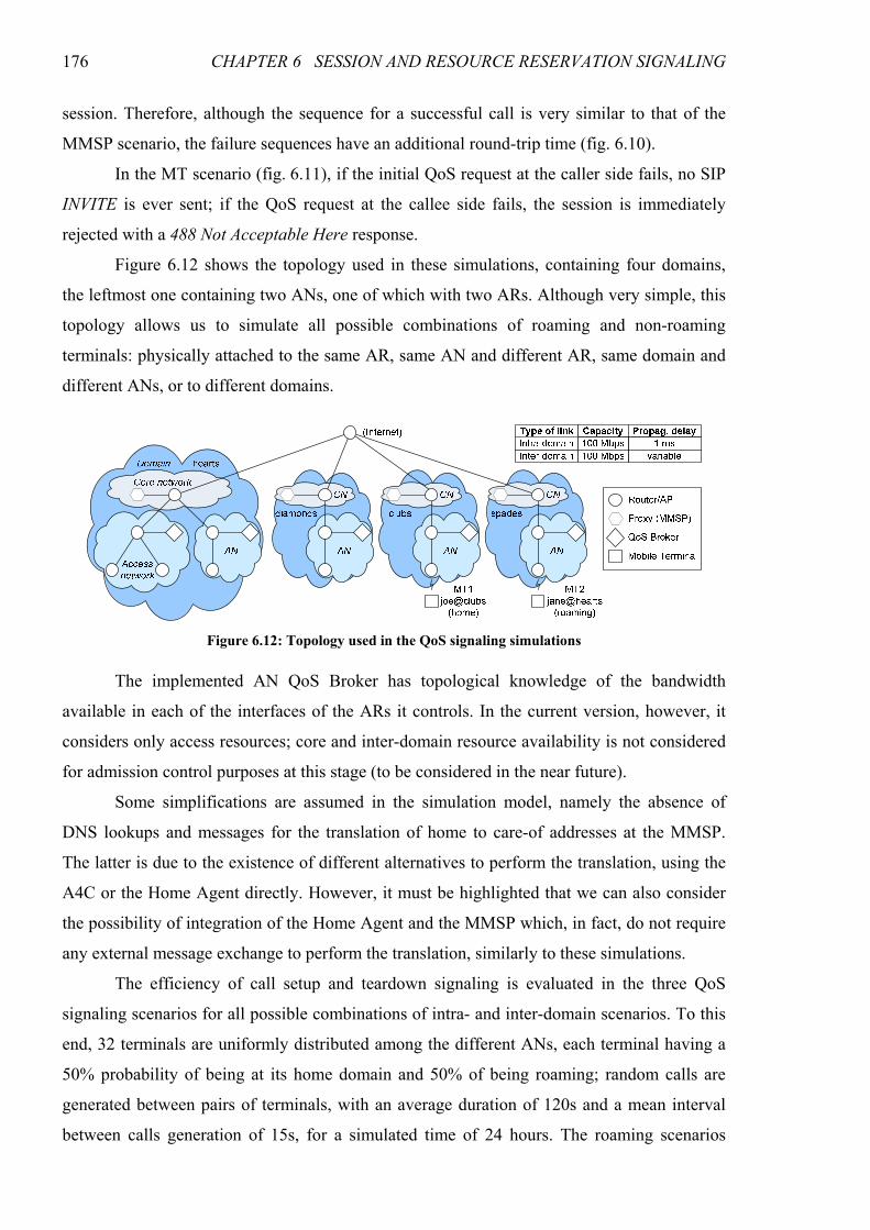
176 CHAPTER 6 SESSION AND RESOURCE RESERVATION SIGNALING
session. Therefore, although the sequence for a successful call is very similar to that of the
MMSP scenario, the failure sequences have an additional round-trip time (fig. 6.10).
In the MT scenario (fig. 6.11), if the initial QoS request at the caller side fails, no SIP
INVITE is ever sent; if the QoS request at the callee side fails, the session is immediately
rejected with a 488 Not Acceptable Here response.
Figure 6.12 shows the topology used in these simulations, containing four domains,
the leftmost one containing two ANs, one of which with two ARs. Although very simple, this
topology allows us to simulate all possible combinations of roaming and non-roaming
terminals: physically attached to the same AR, same AN and different AR, same domain and
different ANs, or to different domains.
The implemented AN QoS Broker has topological knowledge of the bandwidth
available in each of the interfaces of the ARs it controls. In the current version, however, it
considers only access resources; core and inter-domain resource availability is not considered
for admission control purposes at this stage (to be considered in the near future).
Some simplifications are assumed in the simulation model, namely the absence of
DNS lookups and messages for the translation of home to care-of addresses at the MMSP.
The latter is due to the existence of different alternatives to perform the translation, using the
A4C or the Home Agent directly. However, it must be highlighted that we can also consider
the possibility of integration of the Home Agent and the MMSP which, in fact, do not require
any external message exchange to perform the translation, similarly to these simulations.
The efficiency of call setup and teardown signaling is evaluated in the three QoS
signaling scenarios for all possible combinations of intra- and inter-domain scenarios. To this
end, 32 terminals are uniformly distributed among the different ANs, each terminal having a
50% probability of being at its home domain and 50% of being roaming; random calls are
generated between pairs of terminals, with an average duration of 120s and a mean interval
between calls generation of 15s, for a simulated time of 24 hours. The roaming scenarios
Figure 6.12: Topology used in the QoS signaling simulations
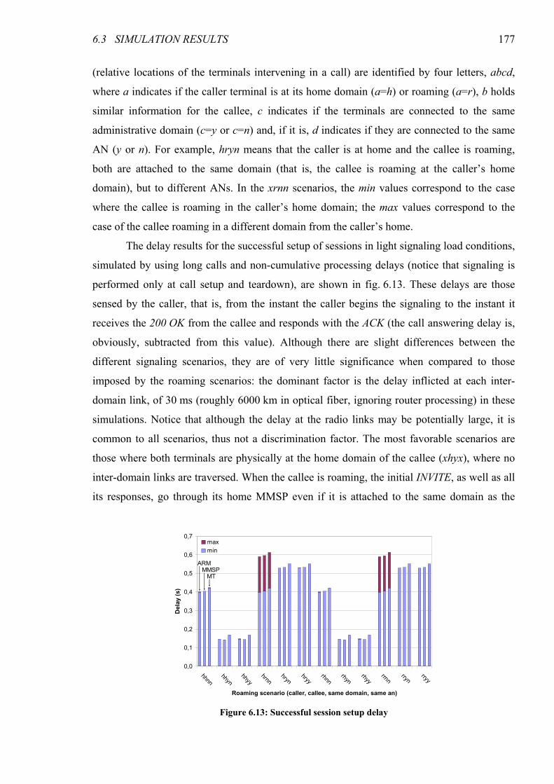
6.3 SIMULATION RESULTS 177
(relative locations of the terminals intervening in a call) are identified by four letters, abcd,
where a indicates if the caller terminal is at its home domain (a=h) or roaming (a=r), b holds
similar information for the callee, c indicates if the terminals are connected to the same
administrative domain (c=y or c=n) and, if it is, d indicates if they are connected to the same
AN (y or n). For example, hryn means that the caller is at home and the callee is roaming,
both are attached to the same domain (that is, the callee is roaming at the caller’s home
domain), but to different ANs. In the xrnn scenarios, the min values correspond to the case
where the callee is roaming in the caller’s home domain; the max values correspond to the
case of the callee roaming in a different domain from the caller’s home.
The delay results for the successful setup of sessions in light signaling load conditions,
simulated by using long calls and non-cumulative processing delays (notice that signaling is
performed only at call setup and teardown), are shown in fig. 6.13. These delays are those
sensed by the caller, that is, from the instant the caller begins the signaling to the instant it
receives the 200 OK from the callee and responds with the ACK (the call answering delay is,
obviously, subtracted from this value). Although there are slight differences between the
different signaling scenarios, they are of very little significance when compared to those
imposed by the roaming scenarios: the dominant factor is the delay inflicted at each inter-
domain link, of 30 ms (roughly 6000 km in optical fiber, ignoring router processing) in these
simulations. Notice that although the delay at the radio links may be potentially large, it is
common to all scenarios, thus not a discrimination factor. The most favorable scenarios are
those where both terminals are physically at the home domain of the callee (xhyx), where no
inter-domain links are traversed. When the callee is roaming, the initial INVITE, as well as all
its responses, go through its home MMSP even if it is attached to the same domain as the
0,0
0,1
0,2
0,3
0,4
0,5
0,6
0,7
hhnnhhyn
hhyyhrnn
hrynhryy
rhnnrhyn
rhyyrrnn
rrynrryy
Roaming scenario (caller, callee, same domain, same an)
Delay (s)
max
min
ARMMMSPMT
Figure 6.13: Successful session setup delay
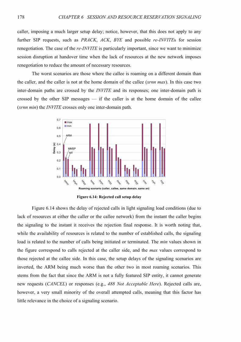
178 CHAPTER 6 SESSION AND RESOURCE RESERVATION SIGNALING
caller, imposing a much larger setup delay; notice, however, that this does not apply to any
further SIP requests, such as PRACK, ACK, BYE and possible re-INVITEs for session
renegotiation. The case of the re-INVITE is particularly important, since we want to minimize
session disruption at handover time when the lack of resources at the new network imposes
renegotiation to reduce the amount of necessary resources.
The worst scenarios are those where the callee is roaming on a different domain than
the caller, and the caller is not at the home domain of the callee (xrnn max). In this case two
inter-domain paths are crossed by the INVITE and its responses; one inter-domain path is
crossed by the other SIP messages — if the caller is at the home domain of the callee
(xrnn min) the INVITE crosses only one inter-domain path.
Figure 6.14 shows the delay of rejected calls in light signaling load conditions (due to
lack of resources at either the caller or the callee network) from the instant the caller begins
the signaling to the instant it receives the rejection final response. It is worth noting that,
while the availability of resources is related to the number of established calls, the signaling
load is related to the number of calls being initiated or terminated. The min values shown in
the figure correspond to calls rejected at the caller side, and the max values correspond to
those rejected at the callee side. In this case, the setup delays of the signaling scenarios are
inverted, the ARM being much worse than the other two in most roaming scenarios. This
stems from the fact that since the ARM is not a fully featured SIP entity, it cannot generate
new requests (CANCEL) or responses (e.g., 488 Not Acceptable Here). Rejected calls are,
however, a very small minority of the overall attempted calls, meaning that this factor has
little relevance in the choice of a signaling scenario.
0,0
0,1
0,2
0,3
0,4
0,5
0,6
0,7
hhnn
hhyn
hhyy
hrnn
hryn
hryy
rhnn
rhyn
rhyy
rrnn
rryn
rryy
Roaming scenario (caller, callee, same domain, same an)
Delay (s)
max
min
ARM
MMSP
MT
Figure 6.14: Rejected call setup delay
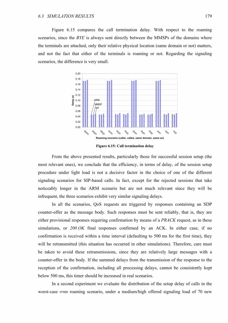
6.3 SIMULATION RESULTS 179
Figure 6.15 compares the call termination delay. With respect to the roaming
scenarios, since the BYE is always sent directly between the MMSPs of the domains where
the terminals are attached, only their relative physical location (same domain or not) matters,
and not the fact that either of the terminals is roaming or not. Regarding the signaling
scenarios, the difference is very small.
From the above presented results, particularly those for successful session setup (the
most relevant ones), we conclude that the efficiency, in terms of delay, of the session setup
procedure under light load is not a decisive factor in the choice of one of the different
signaling scenarios for SIP-based calls. In fact, except for the rejected sessions that take
noticeably longer in the ARM scenario but are not much relevant since they will be
infrequent, the three scenarios exhibit very similar signaling delays.
In all the scenarios, QoS requests are triggered by responses containing an SDP
counter-offer as the message body. Such responses must be sent reliably, that is, they are
either provisional responses requiring confirmation by means of a PRACK request, as in these
simulations, or 200 OK final responses confirmed by an ACK. In either case, if no
confirmation is received within a time interval (defaulting to 500 ms for the first time), they
will be retransmitted (this situation has occurred in other simulations). Therefore, care must
be taken to avoid these retransmissions, since they are relatively large messages with a
counter-offer in the body. If the summed delays from the transmission of the response to the
reception of the confirmation, including all processing delays, cannot be consistently kept
below 500 ms, this timer should be increased in real scenarios.
In a second experiment we evaluate the distribution of the setup delay of calls in the
worst-case rrnn roaming scenario, under a medium/high offered signaling load of 70 new
0,00
0,02
0,04
0,06
0,08
0,10
0,12
0,14
0,16
0,18
0,20
hhnnhhyn
hhyyhrnn
hrynhryy
rhnnrhyn
rhyyrrnn
rrynrryy
Roaming scenario (caller, callee, same domain, same an)
Delay (s)
ARM
MMSP
MT
Figure 6.15: Call termination delay

180 CHAPTER 6 SESSION AND RESOURCE RESERVATION SIGNALING
calls per second, with an exponential distribution of the time interval between generated calls.
We used only 2 ANs in different domains, but a very large number of terminals (3000, 1500
in each AN/domain), in order to support the very large number of simultaneous calls. All the
terminals are roaming and belong to the unused domains. The calls are initiated between a
terminal attached to the first domain and another one attached to the second domain.
Admission control at the AN QoS Brokers was set to always accept the requests.
Figure 6.16 shows the results of this experiment by means of the Cumulative
Distribution Functions of the setup delay in each scenario (for example, 20% of the calls are
established in less than 0.6 s in the MMSP scenario). As can be seen, the setup delay does not
vary significantly, even for the few percent calls where its value is larger. The largest
measured setup delay exceeds the shortest one by 11% in the MMSP scenario, by 9% in the
ARM scenario and by 8% in the MT scenario; for the 99% percentile, the values are 4%, 4%
and 3%, respectively. These are average results of 5 simulation runs of 3600 useful seconds
0
10
20
30
40
50
60
70
80
90
100
0,59 0,60 0,61 0,62 0,63 0,64 0,65 0,66 0,67
Session setup delay (s)
% calls
MMSP
ARM
MT
Figure 6.16: Call setup delay CDF (rrnn, 70 calls/s)
0,50
0,55
0,60
0,65
0,70
0,75
0,80
0,85
0,90
0,95
1,00
0 20 40 60 80 100 120
Calls per second
Call setup delay
MMSP
ARM
MT
Figure 6.17: Percentile 99 call setup delay with variable signaling load
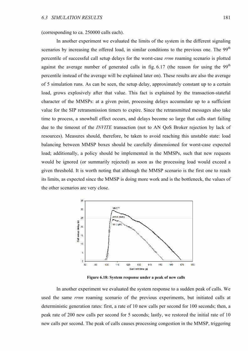
6.3 SIMULATION RESULTS 181
(corresponding to ca. 250000 calls each).
In another experiment we evaluated the limits of the system in the different signaling
scenarios by increasing the offered load, in similar conditions to the previous one. The 99th
percentile of successful call setup delays for the worst-case rrnn roaming scenario is plotted
against the average number of generated calls in fig. 6.17 (the reason for using the 99th
percentile instead of the average will be explained later on). These results are also the average
of 5 simulation runs. As can be seen, the setup delay, approximately constant up to a certain
load, grows explosively after that value. This fact is explained by the transaction-stateful
character of the MMSPs: at a given point, processing delays accumulate up to a sufficient
value for the SIP retransmission timers to expire. Since the retransmitted messages also take
time to process, a snowball effect occurs, and delays become so large that calls start failing
due to the timeout of the INVITE transaction (not to AN QoS Broker rejection by lack of
resources). Measures should, therefore, be taken to avoid reaching this unstable state: load
balancing between MMSP boxes should be carefully dimensioned for worst-case expected
load; additionally, a policy should be implemented in the MMSPs, such that new requests
would be ignored (or summarily rejected) as soon as the processing load would exceed a
given threshold. It is worth noting that although the MMSP scenario is the first one to reach
its limits, as expected since the MMSP is doing more work and is the bottleneck, the values of
the other scenarios are very close.
In another experiment we evaluated the system response to a sudden peak of calls. We
used the same rrnn roaming scenario of the previous experiments, but initiated calls at
deterministic generation rates: first, a rate of 10 new calls per second for 100 seconds; then, a
peak rate of 200 new calls per second for 5 seconds; lastly, we restored the initial rate of 10
new calls per second. The peak of calls causes processing congestion in the MMSP, triggering
Figure 6.18: System response under a peak of new calls
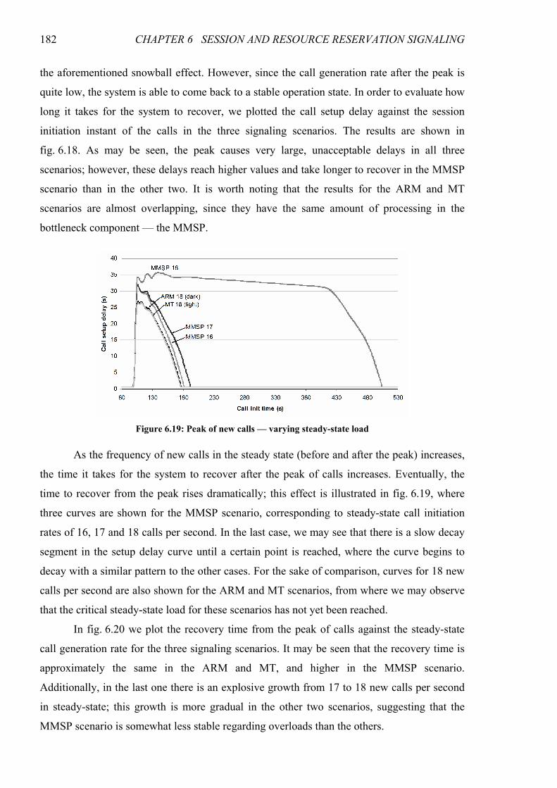
182 CHAPTER 6 SESSION AND RESOURCE RESERVATION SIGNALING
the aforementioned snowball effect. However, since the call generation rate after the peak is
quite low, the system is able to come back to a stable operation state. In order to evaluate how
long it takes for the system to recover, we plotted the call setup delay against the session
initiation instant of the calls in the three signaling scenarios. The results are shown in
fig. 6.18. As may be seen, the peak causes very large, unacceptable delays in all three
scenarios; however, these delays reach higher values and take longer to recover in the MMSP
scenario than in the other two. It is worth noting that the results for the ARM and MT
scenarios are almost overlapping, since they have the same amount of processing in the
bottleneck component — the MMSP.
As the frequency of new calls in the steady state (before and after the peak) increases,
the time it takes for the system to recover after the peak of calls increases. Eventually, the
time to recover from the peak rises dramatically; this effect is illustrated in fig. 6.19, where
three curves are shown for the MMSP scenario, corresponding to steady-state call initiation
rates of 16, 17 and 18 calls per second. In the last case, we may see that there is a slow decay
segment in the setup delay curve until a certain point is reached, where the curve begins to
decay with a similar pattern to the other cases. For the sake of comparison, curves for 18 new
calls per second are also shown for the ARM and MT scenarios, from where we may observe
that the critical steady-state load for these scenarios has not yet been reached.
In fig. 6.20 we plot the recovery time from the peak of calls against the steady-state
call generation rate for the three signaling scenarios. It may be seen that the recovery time is
approximately the same in the ARM and MT, and higher in the MMSP scenario.
Additionally, in the last one there is an explosive growth from 17 to 18 new calls per second
in steady-state; this growth is more gradual in the other two scenarios, suggesting that the
MMSP scenario is somewhat less stable regarding overloads than the others.
Figure 6.19: Peak of new calls — varying steady-state load
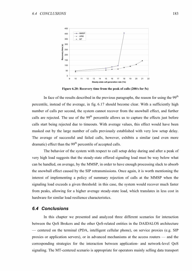
6.4 CONCLUSIONS 183
In face of the results described in the previous paragraphs, the reason for using the 99th
percentile, instead of the average, in fig. 6.17 should become clear. With a sufficiently high
number of calls per second, the system cannot recover from the snowball effect, and further
calls are rejected. The use of the 99th percentile allows us to capture the effects just before
calls start being rejected due to timeouts. With average values, this effect would have been
masked out by the large number of calls previously established with very low setup delay.
The average of successful and failed calls, however, exhibits a similar (and even more
dramatic) effect than the 99th percentile of accepted calls.
The behavior of the system with respect to call setup delay during and after a peak of
very high load suggests that the steady-state offered signaling load must be way below what
can be handled, on average, by the MMSP, in order to have enough processing slack to absorb
the snowball effect caused by the SIP retransmissions. Once again, it is worth mentioning the
interest of implementing a policy of summary rejection of calls at the MMSP when the
signaling load exceeds a given threshold: in this case, the system would recover much faster
from peaks, allowing for a higher average steady-state load, which translates in less cost in
hardware for similar load resilience characteristics.
6.4 Conclusions
In this chapter we presented and analyzed three different scenarios for interaction
between the QoS Brokers and the other QoS-related entities in the DAIDALOS architecture
— centered on the terminal (PDA, intelligent cellular phone), on service proxies (e.g. SIP
proxies or application servers), or in advanced mechanisms at the access routers — and the
corresponding strategies for the interaction between application- and network-level QoS
signaling. The MT-centered scenario is appropriate for operators mainly selling data transport
0
50
100
150
200
250
300
350
400
450
9 10 11 12 13 14 15 16 17 18 19 20 21 22
Steady-state call generation rate (1/s)
Recovery tim
e (s)
MMSP
ARM
MT
Figure 6.20: Recovery time from the peak of calls (200/s for 5s)
184 CHAPTER 6 SESSION AND RESOURCE RESERVATION SIGNALING
with QoS services, the MMSP-centered scenario for operators providing multimedia services
and content, and the ARM-centered scenario for operators providing a set of universally
available network services. We also described how session renegotiation is coordinated with
handover signaling in order to fully explore the resources available in the different network
access technologies.
Through a number of simulation experiments, we compared the behavior of the
different scenarios. The results indicated that under normal operating conditions the efficiency
of the different scenarios is comparable and, therefore, not a relevant factor in the choice of
one over the others. However, under heavy load conditions the MMSP scenario exhibits
overload problems before the other ones. This was an expected result since more functions are
performed by that element, which was the bottleneck component; in the other scenarios, part
of these functions is offloaded to the MT or the ARM. Careful dimensioning of the
components, especially the MMSP, and the provision of generously dimensioned load
balancing is necessary, as the service does not degrade gracefully in overload conditions.
Moreover, the fact that excessive signaling load problems are greatly exacerbated by the
snowball effect of SIP retransmissions means that a policy of summary rejection of new calls
when the processing load reaches a certain threshold at the proxy should be implemented;
such policy would prevent the snowball effect and, therefore, improve the resilience to
signaling overload without the need for costly additional hardware.
185
CHAPTER 7
MOBILITY OPTIMIZATION
Terminal mobility may be handled at different layers. However, although SIP (Session
Initiation Protocol) [RFC3261] may be used for mobility management [Wedlund99,
Schulzrinne00], this function is better handled at layer 3 by Mobile IPv6 (MIPv6) [RFC3775]
even when SIP is used for session control, for several reasons: (1) applications need not worry
about mid-session mobility unless serious changes in available resources force a session
renegotiation, e.g., to a lower bitrate codec; (2) layer 3 mobility support must be in place to
support non-SIP sessions (HTTP, FTP, etc.), and uniform mobility management is desirable
for robustness and flexibility; and (3) seamless mobility may be achieved through the use of
MIPv6 extensions like Fast Handovers [RFC4068]. However, due to the duplication of
mobility management functions, the joint use of SIP and MIPv6 leads to some inefficiency
issues in pre-session mobility, as each protocol is unaware of the other one’s mobility
management capabilities. These issues are even worse when end-to-end resource reservation
must be performed in order to provide appropriate QoS to the session, requiring knowledge of
the points of attachment of both terminals; however, end-to-end resource reservation is
necessary to provide communication services with the same level of quality users have come
to expect from the telephone network. This inefficiency may lead to a significant delay in
session setup, especially in the presence of packet loss (not uncommon in wireless links) and
of large RTTs (Round-Trip Times). In this chapter we propose a scheme for the minimization
of these delays based on simple procedures and cross-layer interactions that make SIP aware
of the terminal’s physical point of attachment, that is, the Care-of Address (CoA). The gains
186 CHAPTER 7 MOBILITY OPTIMIZATION
of the proposal are demonstrated both by a delay analysis and by simulation results. This
work has been published in [Prior07e].
The chapter is organized as follows. Sections 7.1 and 7.1.1 contain an analysis of the
problem and the proposal of the solution, respectively. Section 7.3 describes the SIP
registration procedures. Section 7.4 discusses the relation between the proposed optimizations
and the dormancy/paging support for energy saving. An analytical comparison of the standard
and optimized procedures is presented in section 7.5, and section 0 discusses simulation
results of both. The main conclusions of the work described in this chapter are presented in
section 7.7.
7.1 Inefficiency of SIP with MIPv6
In order to establish a reservation for a flow ensuring that enough resources are
available along the end-to-end path, admission control needs to take into account the available
resources in the complete path, including the access, core and inter-domain path segments. To
this end, each mobile terminal must be aware of its correspondent’s physical location which,
in IP terms, corresponds to its CoA. SIP’s unawareness of pre-session MIPv6 mobility, as will
be seen in the next section, is one of the sources of inefficiency in session initiation signaling.
Mid-session mobility, on the other hand, is handled by MIPv6 with a Fast Handover (FHO)
extension, as described in chapters 5 and 6, and does not require intervention of SIP unless a
large difference in the available resources in the old and new access requires a session
renegotiation. It is worth noting that the use of FHO allows for seamless handovers if mid-
session mobility is performed at layer 3, which is not possible with SIP mobility — while
seamless SIP mobility may be achieved with multihoming, this approach would require two
network interfaces, adding to the cost and energy consumption (therefore, to a lower battery
life) of the mobile terminals.
In this section we analyze the inefficiencies of the joint use of SIP and MIPv6,
particularly in an environment where end-to-end resource reservations must be performed.
The message sequence for initiating a call between two roaming terminals is illustrated in
fig. 7.1. 100 Trying SIP responses and PRACK requests and responses have been omitted in
the figure, since they are not in the critical path of signaling.
The sequence is initiated by the caller sending an INVITE with a message body
containing an offer with a list of codecs supported by itself, along with the corresponding
ports (at the caller end only); this message is sent via the outbound proxy, MMSP1.f. If the
binding cache of MMSP1.f is not up to date with the caller’s current CoA, this INVITE is
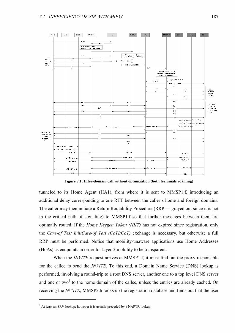
7.1 INEFFICIENCY OF SIP WITH MIPV6 187
tunneled to its Home Agent (HA1), from where it is sent to MMSP1.f, introducing an
additional delay corresponding to one RTT between the caller’s home and foreign domains.
The caller may then initiate a Return Routability Procedure (RRP — grayed out since it is not
in the critical path of signaling) to MMSP1.f so that further messages between them are
optimally routed. If the Home Keygen Token (HKT) has not expired since registration, only
the Care-of Test Init/Care-of Test (CoTI/CoT) exchange is necessary, but otherwise a full
RRP must be performed. Notice that mobility-unaware applications use Home Addresses
(HoAs) as endpoints in order for layer-3 mobility to be transparent.
When the INVITE request arrives at MMSP1.f, it must find out the proxy responsible
for the callee to send the INVITE. To this end, a Domain Name Service (DNS) lookup is
performed, involving a round-trip to a root DNS server, another one to a top level DNS server
and one or two1 to the home domain of the callee, unless the entries are already cached. On
receiving the INVITE, MMSP2.h looks up the registration database and finds out that the user
1 At least an SRV lookup; however it is usually preceded by a NAPTR lookup.
Figure 7.1: Inter-domain call without optimization (both terminals roaming)
188 CHAPTER 7 MOBILITY OPTIMIZATION
(callee) is roaming; DNS lookups are performed to find out the proxy for the foreign (visited)
domain. Notice that service authorization is mandatory, therefore MMSP2.h cannot send the
INVITE directly to the callee, as packet filtering mechanisms would drop it.
MMSP2.f receives the INVITE and fetches the callee’s IP address from its registration
database (for the sake of simplicity, we assume that the callee has registered itself with the IP
address rather than a hostname). Since regular SIP is not layer-3-mobility-aware, this IP
address is a HoA; therefore, the message must go to the callee’s home agent (HA2), from
where it is tunneled to the callee.
When the callee receives the INVITE, it builds a list of the common codecs. In
possession of the IPs and ports at both ends (the caller and itself), the callee may request
resources to/from the caller (QoS Req). However, if resources are reserved for more than the
wireless link, as in our case, the reservation must be made according to the physical points of
attachment of the terminals, that is, their CoAs. The callee knows its own CoA, but not the
caller’s, therefore a Binding Request (BReq)2 must be issued to the caller, which will trigger
an RRP and a Binding Update (BU) from the caller to the callee, adding two RTTs between
them. Since all of these messages must go through the HA of the callee (the caller has no
binding for the callee yet) and some of them (BReq, HoTI and HoT) through the HA of the
caller, this translates in 11 inter-domain traversals (considering that HoTI/HoT, and not
CoTI/CoT, are in the critical path of signaling, as is most common).
The callee also initiates a return routability procedure and binding update to
MMSP2.f, so that future messages need not be tunneled; however, the 183 Session Progress
response must still go through the HA (otherwise MMSP2.f would drop it, since it has no
binding for the callee).
When the caller receives the 183 Session Progress, it knows its own CoA, but not the
callee’s; therefore, it must send a BReq to the callee (symmetrical of the previously mentioned
procedure). Two additional RTTs are, therefore, added (corresponding to 7 inter-domain
traversals, not 11 as the previous one, since the callee already has a binding for the caller).
Only now the HoA and CoA of the callee are known at the caller side, therefore only now a
fully-formed QoS request may be performed at this side. As the amount of available resources
may be less than what was reserved at the callee side, an indication of the final codec
configuration (counter-answer) must be sent in an UPDATE request in order to synchronize
the reservations. Hopefully, by this time all the binding caches are updated, meaning that the
2 Notice that the above mentioned Binding Requests are not entirely compliant with the Binding Refresh Requests defined in
[RFC3775]. Please refer to the note on Binding Requests in section 7.1.1 for details.
7.1 INEFFICIENCY OF SIP WITH MIPV6 189
UPDATE (as well as all further signaling) travels through optimal paths. The media packets
will also use the optimized path, since each terminal has a binding for the media address of
the other one (which is usually the same as the signaling address, except in some multi-homed
terminals).
It is worth noting that many of the inefficiencies (namely, RTTs between foreign and
home domains of the caller, of the callee, and between the foreign domains of both) are due to
the SIP protocol’s unawareness of layer-3 mobility, and to the need to perform end-to-end
resource reservations combined with this unawareness. As we will see in the next section, this
scenario can be significantly improved by means of very simple procedures and cross-layer
interactions.
7.1.1 Note on the Use of Binding Requests
Binding Requests (BReqs) in figure 7.1 behave somewhat differently from the
Binding Refresh Requests (BRRs) defined in [RFC3775], which states that a mobile node
should not respond to BRRs for addresses not in the Binding Update List (BUL). Although it
is possible that the CN will respond with a BU if a packet or sequence of packets of any type
(e.g., dummy packets) is sent to its HoA when it is roaming, we cannot rely on such solution
because:
• There is no guarantee that it will do so.
• If the CN is at home, no BU would ever be received.
Therefore, with the behavior recommended by [RFC3775], it is not possible for a
terminal to know for sure the physical location of the CN in order to perform an end-to-end
reservation.
The reason for rejecting BRRs from nodes not in the BUL is to avoid being subject to
a denial of service attack, since state maintenance is required for the RRP at the MT side.
Unfortunately, it is not possible to make the procedure completely stateless: while the home
and care-of init cookies could be implemented in such a way that the MT would not need to
keep them, the first received keygen token (home or care-of) must be stored until the other
one arrives. It is possible, though, to implement binding requests as used in this work by
having up to a limited number of low priority entries in the BUL used for replying to binding
requests from nodes not in the BUL. These low priority entries are promoted to regular entries
only when the conditions that would normally trigger a BU are met. Due to their limited
number, these low priority entries do not affect the normal operation of the BUL even under a
190 CHAPTER 7 MOBILITY OPTIMIZATION
DoS attack (only a service which is not anyway provided by [RFC3775] may be denied);
under normal conditions, this additional and potentially useful service is provided.
7.2 Optimizing the Use of SIP with MIPv6
The call initiation scenario illustrated in the previous section can be much improved
by means of very simple procedures and cross-layer interactions. In this section we propose a
series of optimizations that allow for a significant reduction in the session setup time, as will
be shown in sections 7.5 and 0.
The first optimization consists on eliminating the need for the INVITE message
between the caller and MMSP1.f to go through the HA. While this could be easily
accomplished by having the terminal keep the MMSP’s cache updated all the time, such
approach would lead to a lot of unnecessary signaling, since most of the time it is not actually
communicating, and would limit its ability to conserve energy using the paging features of the
system. Therefore, we propose a different approach: using the CoA as source IP address of the
packet containing the INVITE message. Notice that the INVITE message itself still uses the
HoA. Responses to the INVITE will be delivered to the CoA since the proxy adds a received
parameter with the source IP address of the packet to the Via header of a received request,
whenever the sent by parameter in the Via header does not match that source IP address (in
our case it contains the HoA). The terminal may then perform the RRP, which is not on the
critical path of signaling, and then maintain MMSP1.f’s binding cache updated for the whole
duration of the call, so that future requests (PRACK, UPDATE, ACK, re-INVITEs, etc.) and
their respective responses will always use the optimized path.
The goal of the second optimization is to eliminate the need for the INVITE message
between MMSP2.f and the callee to go through the callee’s HA. Contrary to the previous
case, the message is not generated at the mobile terminal. In order to use the callee’s CoA as
the destination address, MMSP2.f must have knowledge of the mapping between the callee’s
HoA and CoA, as the HoA is the one used by the application layer. In order to provide this
information, we introduce a cross-layer interaction at MMSP2.h: after retrieving the IP
address (HoA) of the callee from the registration database, MMSP2.h queries the HA to find
out the callee’s current CoA. The Uniform Resource Identifier (URI) in the request line is
then changed to the IP address (HoA), as usual, but with tag containing the current CoA (e.g.,
“coa=FF1E:03AF::1”) appended. Using the CoA from the tag in the request line as the
destination IP address of the packet, MMSP2.f may send the INVITE directly to the callee.
Notice that the use of the CoA tag by MMSP2.f for direct forwarding does not add any

7.2 OPTIMIZING THE USE OF SIP WITH MIPV6 191
security issue to standard SIP, since the same would occur if MMSP2.h had placed the CoA
directly in the request line of the forwarded INVITE.
The third optimization concerns the elimination of the DNS lookup at MMSP2.h when
forwarding the INVITE request: if the registration for redirection includes the IP address of
the inbound proxy where to forward an incoming INVITE (MMSP.f, in this case), no DNS
lookup to find this proxy is necessary. The use of the Path header field described in
[RFC3327] is recommended for conveying this information, while also providing a simple
means of enforcing the traversal of an MMSP at the foreign domain, necessary to perform
service authorization and filtering.
The fourth optimization is related to the need to perform network resource
reservations concerning more than the wireless link. Since the requests are performed for a
path-optimized flow, they must be performed between the physical locations (that is, the
CoA) of both terminals. Once again, we rely on the transport of CoA information in the
application signaling. However, since there is no guarantee that the media will use the same
IP addresses as SIP signaling (particularly with multi-homed terminals), the CoA information
used to this end is conveyed not in SIP, but in the protocol used for session negotiation.
Inclusion of CoA information in Session Description Protocol (SDP) [RFC2327] and SDP
new generation (SDPng) [Kutscher05] is discussed in section 7.2.1.
One might argue that the inclusion of layer 3 mobility information in an application
protocol such as SIP should not be done because it breaks the layering principle; it is worth
noting, however, that not only does the standard SIP already include layer-3 information (IP
addresses) in its headers, but also that cross-layer information would be required by any
protocol with similar characteristics to SIP, namely regarding independence between the
signaling and media interfaces.
7.2.1 Inclusion of CoA Information in SDP(ng)
Media negotiation and configuration for the sessions is performed using either the
SDP or its “new generation” successor, SDPng. The inclusion of CoA information requires
simple extensions to these protocols.
In SDP, the IPv6 address of the media endpoint is conveyed in the c= field [RFC2327,
RFC3266]. Since it is not possible to change the definition of this field without breaking
backward compatibility, it contains the HoA only. For conveying CoA information we resort
to a newly defined attribute, the standard way of extending SDP. This attribute, named coa,
has a similar definition to that of the c= field:
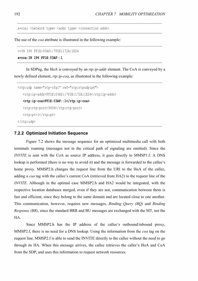
192 CHAPTER 7 MOBILITY OPTIMIZATION
a=coa: <network type> <addr type> <connection addr>
The use of the coa attribute is illustrated in the following example:
c=IN IP6 FF1E:03AD::7F2E:172A:1E24
a=coa:IN IP6 FF1E:03AF::1
In SDPng, the HoA is conveyed by an rtp:ip-addr element. The CoA is conveyed by a
newly defined element, rtp:ip-coa, as illustrated in the following example:
<rtp:udp name="rtp-cfg1" ref="rtp:rtpudpip6">
<rtp:ip-addr>FF1E:03AD::7F2E:172A:1E24</rtp:ip-addr>
<rtp:ip-coa>FF1E:03AF::1</rtp:ip-coa>
<rtp:rtp-port>9456</rtp:rtp-port>
<rtp:pt>1</rtp:pt>
</rtp:udp>
7.2.2 Optimized Initiation Sequence
Figure 7.2 shows the message sequence for an optimized multimedia call with both
terminals roaming (messages not in the critical path of signaling are omitted). Since the
INVITE is sent with the CoA as source IP address, it goes directly to MMSP1.f. A DNS
lookup is performed (there is no way to avoid it) and the message is forwarded to the callee’s
home proxy. MMSP2.h changes the request line from the URI to the HoA of the callee,
adding a coa tag with the callee’s current CoA (retrieved from HA2) to the request line of the
INVITE. Although in the optimal case MMSP2.h and HA2 would be integrated, with the
respective location databases merged, even if they are not, communication between them is
fast and efficient, since they belong to the same domain and are located close to one another.
This communication, however, requires new messages, Binding Query (BQ) and Binding
Response (BR), since the standard BRR and BU messages are exchanged with the MT, not the
HA.
Since MMSP2.h has the IP address of the callee’s outbound/inbound proxy,
MMSP2.f, there is no need for a DNS lookup. Using the information from the coa tag on the
request line, MMSP2.f is able to send the INVITE directly to the callee without the need to go
through its HA. When this message arrives, the callee retrieves the caller’s HoA and CoA
from the SDP, and uses this information to request network resources.
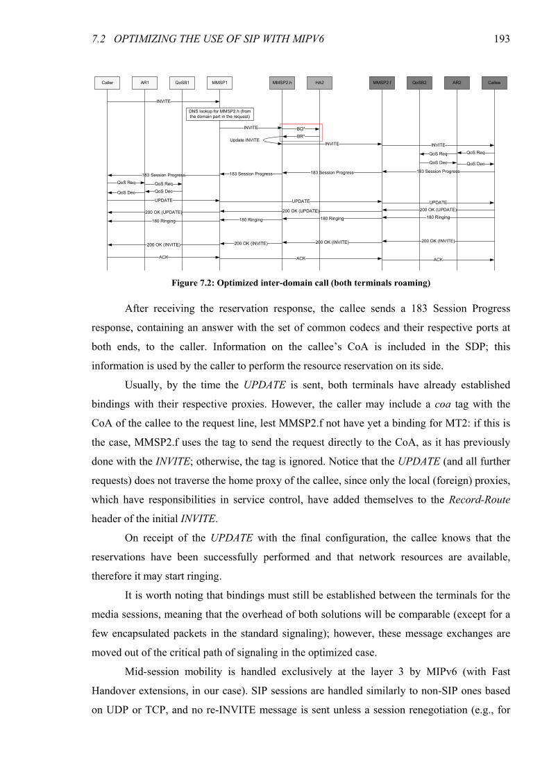
7.2 OPTIMIZING THE USE OF SIP WITH MIPV6 193
After receiving the reservation response, the callee sends a 183 Session Progress
response, containing an answer with the set of common codecs and their respective ports at
both ends, to the caller. Information on the callee’s CoA is included in the SDP; this
information is used by the caller to perform the resource reservation on its side.
Usually, by the time the UPDATE is sent, both terminals have already established
bindings with their respective proxies. However, the caller may include a coa tag with the
CoA of the callee to the request line, lest MMSP2.f not have yet a binding for MT2: if this is
the case, MMSP2.f uses the tag to send the request directly to the CoA, as it has previously
done with the INVITE; otherwise, the tag is ignored. Notice that the UPDATE (and all further
requests) does not traverse the home proxy of the callee, since only the local (foreign) proxies,
which have responsibilities in service control, have added themselves to the Record-Route
header of the initial INVITE.
On receipt of the UPDATE with the final configuration, the callee knows that the
reservations have been successfully performed and that network resources are available,
therefore it may start ringing.
It is worth noting that bindings must still be established between the terminals for the
media sessions, meaning that the overhead of both solutions will be comparable (except for a
few encapsulated packets in the standard signaling); however, these message exchanges are
moved out of the critical path of signaling in the optimized case.
Mid-session mobility is handled exclusively at the layer 3 by MIPv6 (with Fast
Handover extensions, in our case). SIP sessions are handled similarly to non-SIP ones based
on UDP or TCP, and no re-INVITE message is sent unless a session renegotiation (e.g., for
Caller CalleeAR1 AR2QoSB1 MMSP1 MMSP2.f QoSB2MMSP2.h HA2
INVITE
INVITE BQ*
BR*Update INVITE
INVITE INVITE
183 Session Progress183 Session Progress183 Session Progress183 Session Progress
UPDATE UPDATE UPDATE
200 OK (UPDATE)200 OK (UPDATE)200 OK (UPDATE)180 Ringing180 Ringing180 Ringing
200 OK (INVITE)200 OK (INVITE)200 OK (INVITE)
180 Ringing
200 OK (INVITE)
ACK ACK ACK
DNS lookup for MMSP2.h (from
the domain part in the request)
QoS ReqQoS Req
QoS Dec QoS Dec
QoS Req QoS Req
QoS DecQoS Dec
Figure 7.2: Optimized inter-domain call (both terminals roaming)
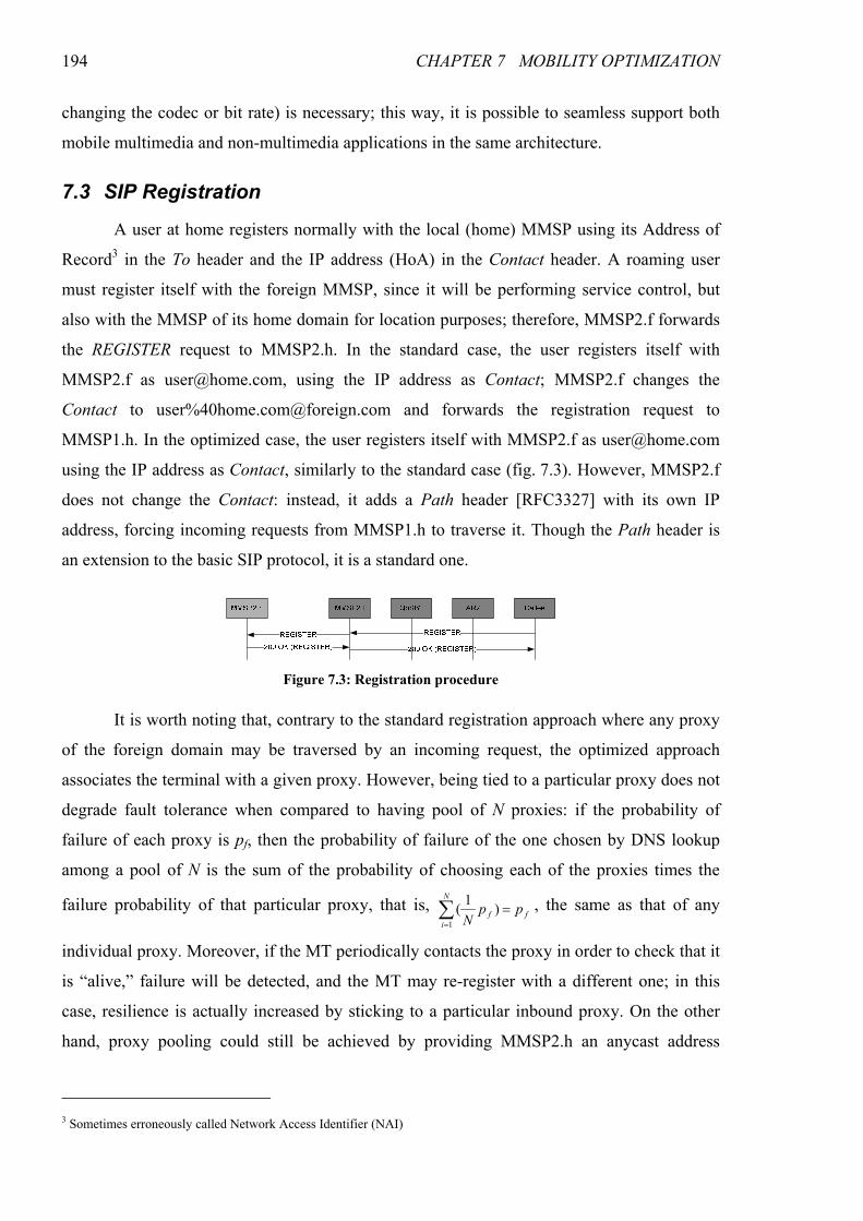
194 CHAPTER 7 MOBILITY OPTIMIZATION
changing the codec or bit rate) is necessary; this way, it is possible to seamless support both
mobile multimedia and non-multimedia applications in the same architecture.
7.3 SIP Registration
A user at home registers normally with the local (home) MMSP using its Address of
Record3 in the To header and the IP address (HoA) in the Contact header. A roaming user
must register itself with the foreign MMSP, since it will be performing service control, but
also with the MMSP of its home domain for location purposes; therefore, MMSP2.f forwards
the REGISTER request to MMSP2.h. In the standard case, the user registers itself with
MMSP2.f as [email protected], using the IP address as Contact; MMSP2.f changes the
Contact to user%[email protected] and forwards the registration request to
MMSP1.h. In the optimized case, the user registers itself with MMSP2.f as [email protected]
using the IP address as Contact, similarly to the standard case (fig. 7.3). However, MMSP2.f
does not change the Contact: instead, it adds a Path header [RFC3327] with its own IP
address, forcing incoming requests from MMSP1.h to traverse it. Though the Path header is
an extension to the basic SIP protocol, it is a standard one.
It is worth noting that, contrary to the standard registration approach where any proxy
of the foreign domain may be traversed by an incoming request, the optimized approach
associates the terminal with a given proxy. However, being tied to a particular proxy does not
degrade fault tolerance when compared to having pool of N proxies: if the probability of
failure of each proxy is pf, then the probability of failure of the one chosen by DNS lookup
among a pool of N is the sum of the probability of choosing each of the proxies times the
failure probability of that particular proxy, that is, ∑=
=N
i
ff ppN1
)1( , the same as that of any
individual proxy. Moreover, if the MT periodically contacts the proxy in order to check that it
is “alive,” failure will be detected, and the MT may re-register with a different one; in this
case, resilience is actually increased by sticking to a particular inbound proxy. On the other
hand, proxy pooling could still be achieved by providing MMSP2.h an anycast address
3 Sometimes erroneously called Network Access Identifier (NAI)
Figure 7.3: Registration procedure

7.5 DELAY ANALYSIS 195
instead of the regular unicast address of MMSP2.f at registration time, using a method like the
one proposed in [Engel98].
7.4 Issues with Dormancy/Paging
Energy is a scarce resource in mobile terminals, particularly in the smaller and lighter-
weighted ones. Therefore, any architecture where small and low-power devices are
foreseeable must provide some mechanism for dormancy/power saving. In our architecture,
support for dormancy is provided by the Paging Controller (PC). This entity provides an
alternate CoA to the MT. When packets arrive, the PC buffers them and informs the terminal
that it must wake up; when the MT wakes up, the buffered packets are delivered and the MT
starts using its new, real CoA (more details in [Banchs05]).
Support for dormancy/paging disallows keeping fresh the binding cache of
correspondent entities, namely MMSPs: the terminal only acquires a real CoA when it wakes
up; therefore, only after waking up it can update the correspondents’ binding caches. If the
terminals are idle for long periods of time, as usually happens with mobile phones, the
probability that the newly acquired CoA differs from the one the terminal had before going
asleep is pretty high, even with slow mobility patterns. Dormancy/paging also introduces an
additional delay in any message received, corresponding to the time it takes for the terminal to
be located and waken up. Other than these, dormancy/paging has no issues: the alternate CoA
provided by the PC may be used for location purposes as does the real CoA. Notice that this
dormancy/paging affects only the reception of the initial INVITE.
7.5 Delay Analysis
In this section we perform a comparative analysis of the dial-to-ringtone delay with
standard and optimized signaling for a call between two roaming terminals (processing delays
at the nodes are not accounted for). In order to simplify our analysis, the following
assumptions have been made:
• Inter-domain delays are symmetrical, i.e., it takes about the same time to go from A to B
as from B to A.
• Compared to the delay a message suffers in the wireless link or in inter-domain trips, the
delay in intra-domain wired links is minimal and may, therefore, be neglected.
• In the RRP, the HoTI/HoT exchange takes longer than the CoTI/CoT.
• An RRP from a terminal to a local MMSP takes less time than the same procedure to a
remote terminal, provided the HA is the same in both cases.

196 CHAPTER 7 MOBILITY OPTIMIZATION
• The BU from the Caller arrives at MMSP1.f before the 183 Session Progress in the
sequence of fig. 7.1, meaning that the 183 S.P. will not go through the HA even in the
standard case. This is almost always true, failing only if the inter-domain delay between
the home and foreign domains of the caller is disproportionately large compared to the
other delays.
In this analysis we will use the following notation: TW1 and TW2 are the delay at the
wireless links of the caller and the callee, respectively; TF1F2, TF1H1, TF1H2, TF2H1 and TF2H2 are
the inter-domain one way trip delays (between combinations of the Foreign and Home
domains of the caller — 1 — and the callee — 2); TDNS1 and TDNS2 are the delays for DNS
lookups of the home and the foreign domains of the callee, respectively. Notice that if the
entries are not cached, the DNS lookups imply at least one RTT to the DNS registrar, to find
out the DNS server of the domain to be resolved, and another one or two to that domain, to
find out the address of a SIP proxy (SRV record and, eventually, NAPTR record).
7.5.1 Standard Case
With standard, non-optimized signaling (refer to fig. 7.1), the INVITE takes TInv
(eq. 7.1) to go from the caller to the callee. The QoS request can only be initiated after the
caller’s CoA has been found, which takes TCoA1 (eq. 7.2). The QoS request/response at the
callee side takes TQoS1 (eq. 7.3). Then, the 183 Session Progress takes TSP (eq. 7.4) to go from
the callee to the caller. Finding out the callee’s CoA takes TCoA2 (eq. 7.5). The QoS
request/response at the caller side takes TQoS2 (eq. 7.6). Finally, the PRACK is sent to the
callee with the SDP counter-answer, after which it may start ringing. Until the 180 Ringing
arrives at the caller, there is an additional TPra (eq. 7.7). Adding all these delays, we obtain a
total dial-to-ringtone delay of TStd (eq. 7.8).
2222211111 32 WHFDNSHFDNSHFWInv TTTTTTTT ++++++= (7.1)
21112122211 33444 HFHFHHHFWWCoA TTTTTTT +++++= (7.2)
21 2 WQoS TT = (7.3)
212221 HFHFWWSP TTTTT +++= (7.4)
212221212 334 FFHFHFWWCoA TTTTTT ++++= (7.5)
12 2 WQoS TT = (7.6)
21222121 22 HFHFFFWWPra TTTTTT ++++= (7.7)
212221112121 127521414 DNSDNSHFHFHFFFWWStd TTTTTTTTT +++++++= (7.8)
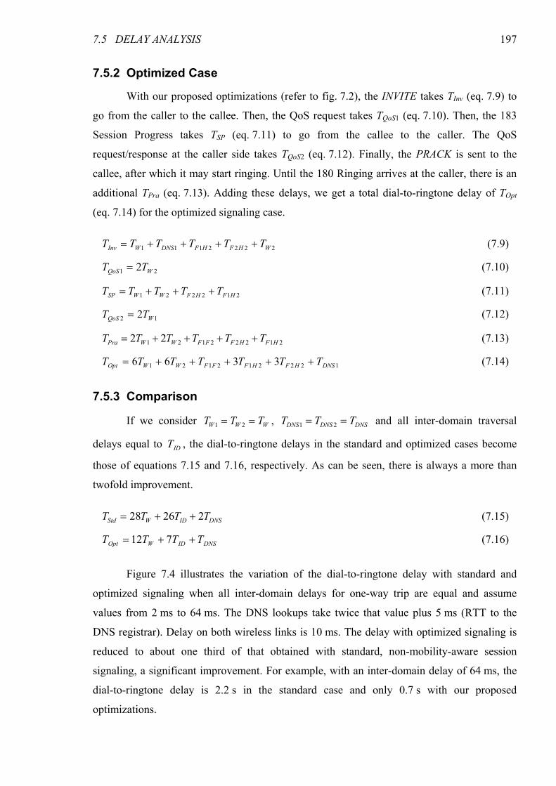
7.5 DELAY ANALYSIS 197
7.5.2 Optimized Case
With our proposed optimizations (refer to fig. 7.2), the INVITE takes TInv (eq. 7.9) to
go from the caller to the callee. Then, the QoS request takes TQoS1 (eq. 7.10). Then, the 183
Session Progress takes TSP (eq. 7.11) to go from the callee to the caller. The QoS
request/response at the caller side takes TQoS2 (eq. 7.12). Finally, the PRACK is sent to the
callee, after which it may start ringing. Until the 180 Ringing arrives at the caller, there is an
additional TPra (eq. 7.13). Adding these delays, we get a total dial-to-ringtone delay of TOpt
(eq. 7.14) for the optimized signaling case.
2222111 WHFHFDNSWInv TTTTTT ++++= (7.9)
21 2 WQoS TT = (7.10)
212221 HFHFWWSP TTTTT +++= (7.11)
12 2 WQoS TT = (7.12)
21222121 22 HFHFFFWWPra TTTTTT ++++= (7.13)
122212121 3366 DNSHFHFFFWWOpt TTTTTTT +++++= (7.14)
7.5.3 Comparison
If we consider WWW TTT == 21 , DNSDNSDNS TTT == 21 and all inter-domain traversal
delays equal to IDT , the dial-to-ringtone delays in the standard and optimized cases become
those of equations 7.15 and 7.16, respectively. As can be seen, there is always a more than
twofold improvement.
DNSIDWStd TTTT 22628 ++= (7.15)
DNSIDWOpt TTTT ++= 712 (7.16)
Figure 7.4 illustrates the variation of the dial-to-ringtone delay with standard and
optimized signaling when all inter-domain delays for one-way trip are equal and assume
values from 2 ms to 64 ms. The DNS lookups take twice that value plus 5 ms (RTT to the
DNS registrar). Delay on both wireless links is 10 ms. The delay with optimized signaling is
reduced to about one third of that obtained with standard, non-mobility-aware session
signaling, a significant improvement. For example, with an inter-domain delay of 64 ms, the
dial-to-ringtone delay is 2.2 s in the standard case and only 0.7 s with our proposed
optimizations.
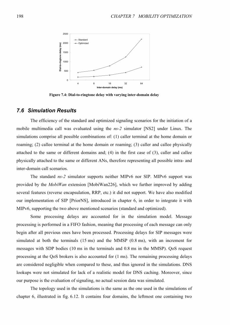
198 CHAPTER 7 MOBILITY OPTIMIZATION
7.6 Simulation Results
The efficiency of the standard and optimized signaling scenarios for the initiation of a
mobile multimedia call was evaluated using the ns-2 simulator [NS2] under Linux. The
simulations comprise all possible combinations of: (1) caller terminal at the home domain or
roaming; (2) callee terminal at the home domain or roaming; (3) caller and callee physically
attached to the same or different domains and; (4) in the first case of (3), caller and callee
physically attached to the same or different ANs, therefore representing all possible intra- and
inter-domain call scenarios.
The standard ns-2 simulator supports neither MIPv6 nor SIP. MIPv6 support was
provided by the MobiWan extension [MobiWan226], which we further improved by adding
several features (reverse encapsulation, RRP, etc.) it did not support. We have also modified
our implementation of SIP [PriorNS], introduced in chapter 6, in order to integrate it with
MIPv6, supporting the two above mentioned scenarios (standard and optimized).
Some processing delays are accounted for in the simulation model. Message
processing is performed in a FIFO fashion, meaning that processing of each message can only
begin after all previous ones have been processed. Processing delays for SIP messages were
simulated at both the terminals (15 ms) and the MMSP (0.8 ms), with an increment for
messages with SDP bodies (10 ms in the terminals and 0.8 ms in the MMSP). QoS request
processing at the QoS brokers is also accounted for (1 ms). The remaining processing delays
are considered negligible when compared to these, and thus ignored in the simulations. DNS
lookups were not simulated for lack of a realistic model for DNS caching. Moreover, since
our purpose is the evaluation of signaling, no actual session data was simulated.
The topology used in the simulations is the same as the one used in the simulations of
chapter 6, illustrated in fig. 6.12. It contains four domains, the leftmost one containing two
0
500
1000
1500
2000
2500
4 8 16 32 64
Inter-domain delay (ms)
Dial-to-ringtone delay (ms)
Standard
Optimized
Figure 7.4: Dial-to-ringtone delay with varying inter-domain delay
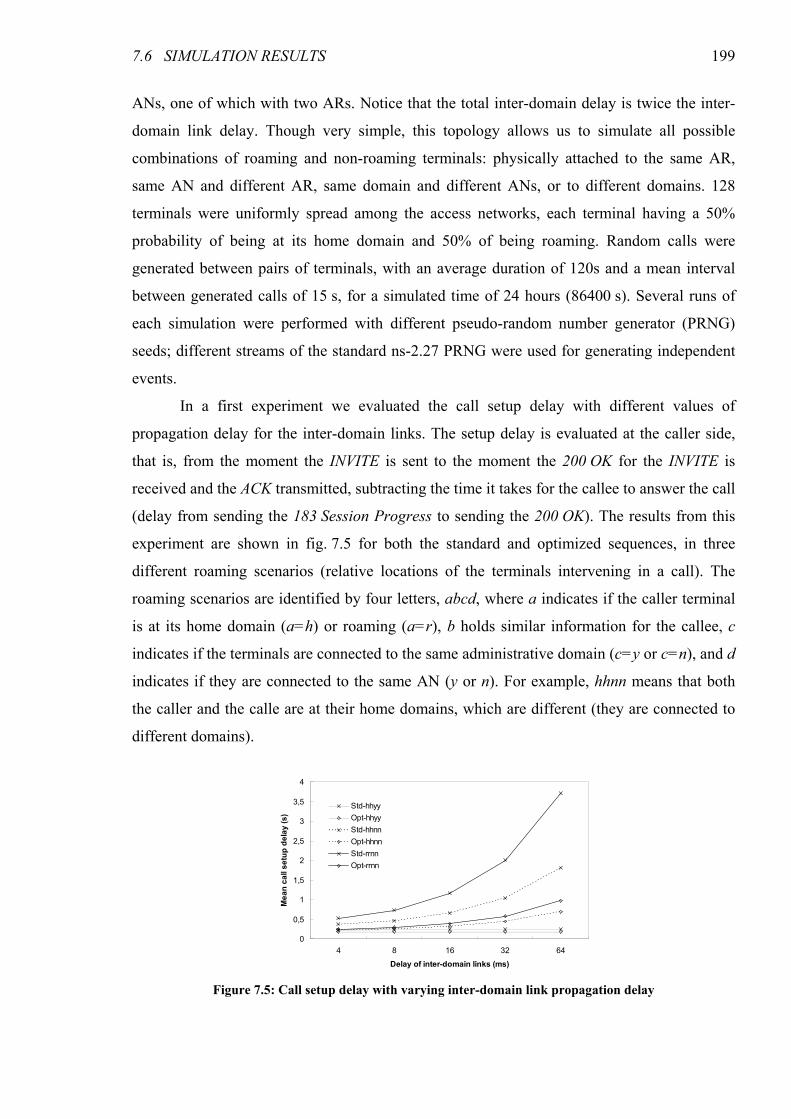
7.6 SIMULATION RESULTS 199
ANs, one of which with two ARs. Notice that the total inter-domain delay is twice the inter-
domain link delay. Though very simple, this topology allows us to simulate all possible
combinations of roaming and non-roaming terminals: physically attached to the same AR,
same AN and different AR, same domain and different ANs, or to different domains. 128
terminals were uniformly spread among the access networks, each terminal having a 50%
probability of being at its home domain and 50% of being roaming. Random calls were
generated between pairs of terminals, with an average duration of 120s and a mean interval
between generated calls of 15 s, for a simulated time of 24 hours (86400 s). Several runs of
each simulation were performed with different pseudo-random number generator (PRNG)
seeds; different streams of the standard ns-2.27 PRNG were used for generating independent
events.
In a first experiment we evaluated the call setup delay with different values of
propagation delay for the inter-domain links. The setup delay is evaluated at the caller side,
that is, from the moment the INVITE is sent to the moment the 200 OK for the INVITE is
received and the ACK transmitted, subtracting the time it takes for the callee to answer the call
(delay from sending the 183 Session Progress to sending the 200 OK). The results from this
experiment are shown in fig. 7.5 for both the standard and optimized sequences, in three
different roaming scenarios (relative locations of the terminals intervening in a call). The
roaming scenarios are identified by four letters, abcd, where a indicates if the caller terminal
is at its home domain (a=h) or roaming (a=r), b holds similar information for the callee, c
indicates if the terminals are connected to the same administrative domain (c=y or c=n), and d
indicates if they are connected to the same AN (y or n). For example, hhnn means that both
the caller and the calle are at their home domains, which are different (they are connected to
different domains).
0
0,5
1
1,5
2
2,5
3
3,5
4
4 8 16 32 64
Delay of inter-domain links (ms)
Mean call setup delay (s)
Std-hhyy
Opt-hhyy
Std-hhnn
Opt-hhnn
Std-rrnn
Opt-rrnn
Figure 7.5: Call setup delay with varying inter-domain link propagation delay
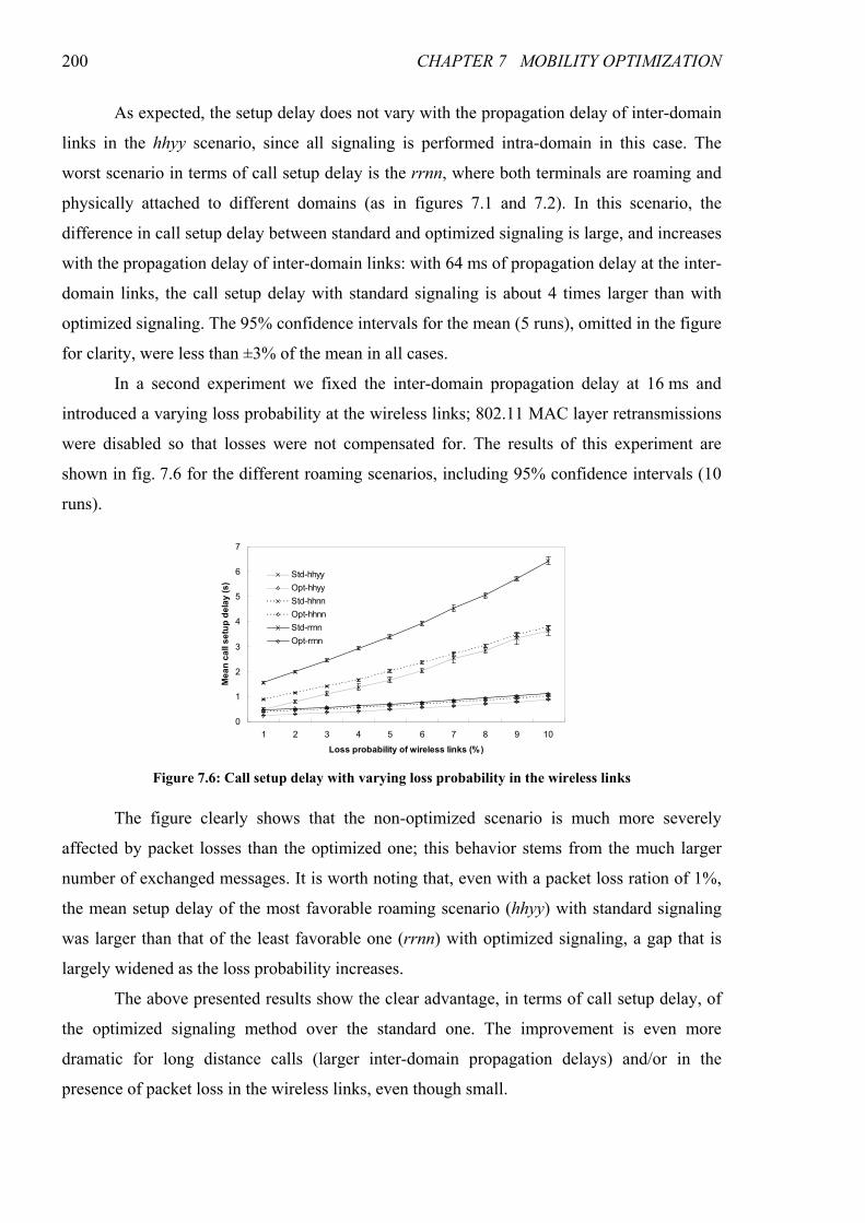
200 CHAPTER 7 MOBILITY OPTIMIZATION
As expected, the setup delay does not vary with the propagation delay of inter-domain
links in the hhyy scenario, since all signaling is performed intra-domain in this case. The
worst scenario in terms of call setup delay is the rrnn, where both terminals are roaming and
physically attached to different domains (as in figures 7.1 and 7.2). In this scenario, the
difference in call setup delay between standard and optimized signaling is large, and increases
with the propagation delay of inter-domain links: with 64 ms of propagation delay at the inter-
domain links, the call setup delay with standard signaling is about 4 times larger than with
optimized signaling. The 95% confidence intervals for the mean (5 runs), omitted in the figure
for clarity, were less than ±3% of the mean in all cases.
In a second experiment we fixed the inter-domain propagation delay at 16 ms and
introduced a varying loss probability at the wireless links; 802.11 MAC layer retransmissions
were disabled so that losses were not compensated for. The results of this experiment are
shown in fig. 7.6 for the different roaming scenarios, including 95% confidence intervals (10
runs).
The figure clearly shows that the non-optimized scenario is much more severely
affected by packet losses than the optimized one; this behavior stems from the much larger
number of exchanged messages. It is worth noting that, even with a packet loss ration of 1%,
the mean setup delay of the most favorable roaming scenario (hhyy) with standard signaling
was larger than that of the least favorable one (rrnn) with optimized signaling, a gap that is
largely widened as the loss probability increases.
The above presented results show the clear advantage, in terms of call setup delay, of
the optimized signaling method over the standard one. The improvement is even more
dramatic for long distance calls (larger inter-domain propagation delays) and/or in the
presence of packet loss in the wireless links, even though small.
0
1
2
3
4
5
6
7
1 2 3 4 5 6 7 8 9 10
Loss probability of wireless links (%)
Mean call setup delay (s)
Std-hhyy
Opt-hhyy
Std-hhnn
Opt-hhnn
Std-rrnn
Opt-rrnn
Figure 7.6: Call setup delay with varying loss probability in the wireless links
7.7 CONCLUSIONS 201
7.7 Conclusions
In this chapter we identified the sources of inefficiency with the joint use of SIP and
Mobile IPv6 (the probable protocols for session initiation and mobility support, respectively,
in the next generation telecommunication systems) for the initiation of mobile multimedia
applications, particularly when end-to-end resource reservations must be performed for the
media. This inefficiency generally stems from SIP/SDP’s unawareness of layer 3 mobility,
and from the need to perform resource reservations accounting for the physical points of
attachment of the terminals combined with that unawareness. A solution for these
inefficiencies was proposed, based on the direct use of the Care-of Addresses in some
messages (namely in the short-lived message transactions in call initiation) and on cross-layer
interactions (use of layer 3 location information in session setup signaling).
The advantages of the proposed optimizations in session establishment were analyzed,
and simulation results have demonstrated that the session initiation sequence is much faster
with the optimizations than in the standard case, particularly in the presence of larger inter-
domain link propagation delays (long distance calls) or packet loss in the wireless links.

203
CHAPTER 8
INTER-DOMAIN QOS
The provision of multimedia services with real-time requirements in the Internet
across domain boundaries is conditioned by the ability to ensure that certain Quality of
Service requirements are met. The introduction of QoS routing mechanisms able to select
paths with the required characteristics is of major importance towards this goal. Though much
attention has been paid to QoS in IP networks, most of the effort has been centered on intra-
domain; much less has been done in the scope of inter-domain, a much more complex
problem, for a number of reasons. The Internet is a complex entity, comprised of a large
number of Autonomous Systems (ASs) managed by very diverse operators. If it is to be
widely deployed, an inter-domain QoS routing mechanism must be capable of handling the
heterogeneity of the Internet and impose minimum requirements on intra-domain routing, in
order to be appealing to the different operators. The introduction of QoS metrics should not
disrupt currently existing inter-domain routing: the QoS and non-QoS versions should
interoperate, allowing for incremental deployment among the different networks, and the
stability of the routes should not be overly affected by the QoS mechanisms. A final
requirement is scalability: a solution that does not scale to the dimension of the Internet
cannot be deployed widely enough to be useful.
In this chapter, we address the problem of inter-domain QoS routing, part of the
overall solution to the problem of end-to-end QoS, introduced in chapter 5. Our proposal is
based on Service-Level Agreements (SLAs) for data transport between peering domains,
using virtual-trunk type aggregates. The problem is formally stated and formulated in Integer
204 CHAPTER 8 INTER-DOMAIN QOS
Linear Programming (ILP), and proof is given that routes obtained through the optimization
process are cycle-free. We propose a practical solution for inter-domain QoS routing based on
both static and coarse-grained dynamic metrics: it uses the light load delay and assigned
bandwidth (both static) in order to improve the packet QoS and make better use of network
resources, and a coarse-grained dynamic metric for path congestion, intended to avoid
overloaded paths. We define the QoS_INFO extension to the Border Gateway Protocol (BGP)
[RFC4271] to transport these QoS metrics and the algorithm to use them for path selection.
Using the ns-2 simulator [NS2], we compare the proposed protocol with standard BGP and
with BGP with the QoS_NLRI extension [Cristallo04] conveying static one-way delay
information (expected route delay in light load conditions). Optimal solutions for the same
topology and traffic matrix, obtained using the ILP formulation in a MIP (Mixed Integer
Programming) code, are also used as baselines for comparison. Results show that the QoS
parameters of the route set obtained with QoS_INFO are the closest to those of the optimal
route set. Specifically, we show that congestion and packet losses are much lower with
QoS_INFO than with standard BGP or with QoS_NLRI. Parts of this work have been
published in [Prior06a], [Prior07b], [Prior07c] and [Prior07d].
The rest of the chapter is organized as follows. Next section contains the formal
description of the problem and its formulation in ILP. Section 8.2 presents the proposed
protocol and the associated path selection algorithm. In section 8.3 we compare the optimal
results with simulation results from standard BGP, QoS_NLRI and QoS_INFO. Finally,
section 8.4 contains a summary of the conclusions of this chapter.
8.1 Inter-Domain QoS Routing with Virtual Trunks
In this section we formally describe the problem of inter-domain routing with virtual
trunks and formulate it as an ILP problem. In section 8.3, this formulation will be used in a
MIP solver to obtain optimal route sets, against which we compare the results of our proposal.
8.1.1 Virtual Trunk Model of the Autonomous Systems
Though the use of some inner information of the ASs is important for inter-domain
QoS routing, information on the exact topology and configuration of the ASs should not be
used for inter-domain routing for two reasons: (1) the level of detail would be excessive,
complicating the route computation task and, most important, (2) network operators usually
want to disclose the minimum possible amount of internal information about their networks.
In the work presented in this chapter, we use a “black box” model where only
externally observable AS information is disclosed. The intra-domain connections between
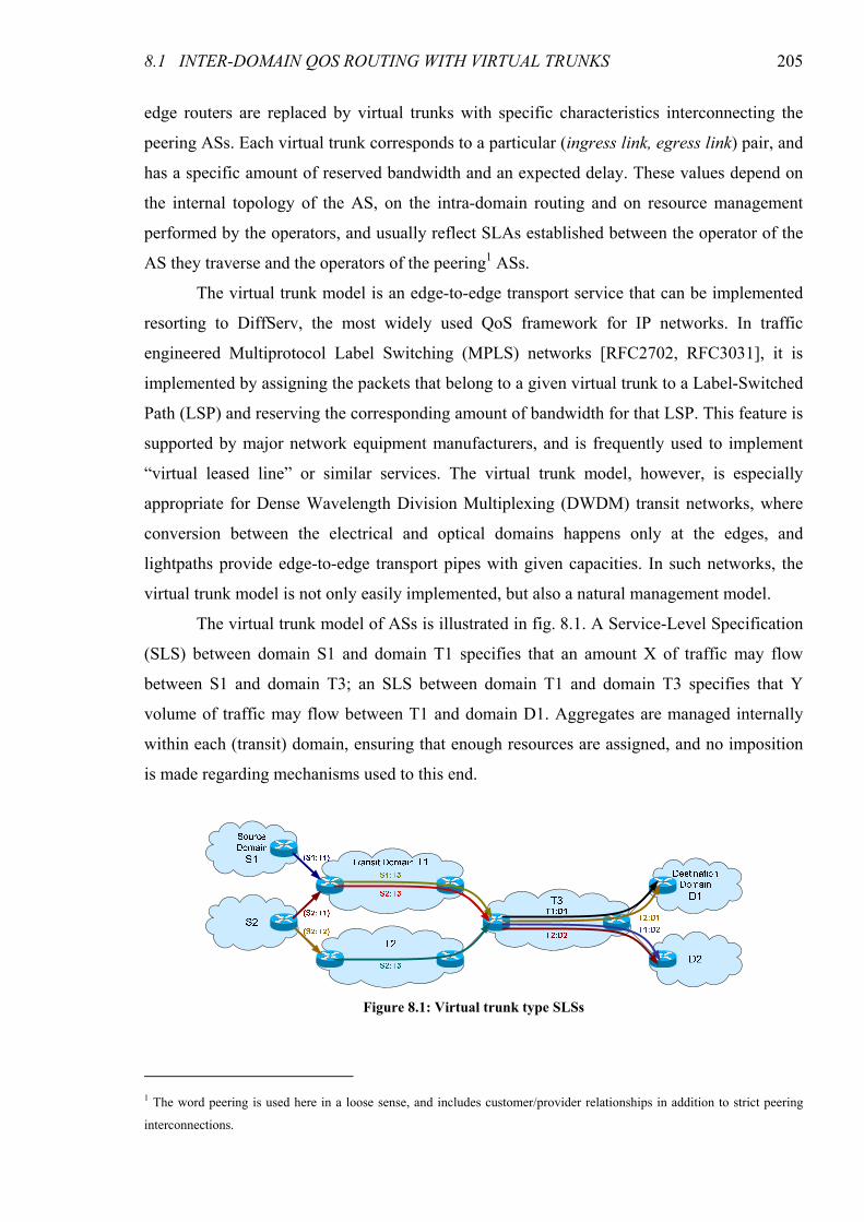
8.1 INTER-DOMAIN QOS ROUTING WITH VIRTUAL TRUNKS 205
edge routers are replaced by virtual trunks with specific characteristics interconnecting the
peering ASs. Each virtual trunk corresponds to a particular (ingress link, egress link) pair, and
has a specific amount of reserved bandwidth and an expected delay. These values depend on
the internal topology of the AS, on the intra-domain routing and on resource management
performed by the operators, and usually reflect SLAs established between the operator of the
AS they traverse and the operators of the peering1 ASs.
The virtual trunk model is an edge-to-edge transport service that can be implemented
resorting to DiffServ, the most widely used QoS framework for IP networks. In traffic
engineered Multiprotocol Label Switching (MPLS) networks [RFC2702, RFC3031], it is
implemented by assigning the packets that belong to a given virtual trunk to a Label-Switched
Path (LSP) and reserving the corresponding amount of bandwidth for that LSP. This feature is
supported by major network equipment manufacturers, and is frequently used to implement
“virtual leased line” or similar services. The virtual trunk model, however, is especially
appropriate for Dense Wavelength Division Multiplexing (DWDM) transit networks, where
conversion between the electrical and optical domains happens only at the edges, and
lightpaths provide edge-to-edge transport pipes with given capacities. In such networks, the
virtual trunk model is not only easily implemented, but also a natural management model.
The virtual trunk model of ASs is illustrated in fig. 8.1. A Service-Level Specification
(SLS) between domain S1 and domain T1 specifies that an amount X of traffic may flow
between S1 and domain T3; an SLS between domain T1 and domain T3 specifies that Y
volume of traffic may flow between T1 and domain D1. Aggregates are managed internally
within each (transit) domain, ensuring that enough resources are assigned, and no imposition
is made regarding mechanisms used to this end.
1 The word peering is used here in a loose sense, and includes customer/provider relationships in addition to strict peering
interconnections.
Figure 8.1: Virtual trunk type SLSs
206 CHAPTER 8 INTER-DOMAIN QOS
The configuration of the virtual trunks must be consistent with the inter-domain links.
In particular, the summed bandwidth of all virtual trunks traversing AS j and going to AS k
must be less than the bandwidth of the inter-domain link connecting ASs j and k; similarly,
the summed bandwidth of all virtual trunks coming from AS i and traversing AS j must be
less than the bandwidth of the inter-domain link connecting ASs i and j.
8.1.2 Problem Statement
Let ),( EVG = be an undirected graph with edge capacities jic , and edge delays jiw , .
Each node represents an AS, and the edges correspond to the inter-domain links. Additionally,
let us define a set F of aggregate flows between pairs of nodes and a corresponding matrix of
traffic demands dsa , for all 2),( Vds ∈ , where s and d denote the source and destination
nodes, respectively.
Given any triplet ),,( kji of nodes such that i is directly connected to j and j is
directly connected to k (that is, { } Ekjji ⊂},{},,{ ), there may be a traffic contract (SLS)
stating that j provides a virtual trunk between i and k with reserved capacity kjir ,, . The
volume of data transported from i to k via j per time unit is, therefore, bounded by kjir ,, . If
no such contract exists, we say that 0,, =kjir . Since each virtual trunk is mapped to an actual
path inside the AS, it has an associated delay kjiy ,, , corresponding to the delay of that path.
Call L the set of all virtual trunks ),,( kji .
The virtual trunks must satisfy the conditions kj
i
kjikj cro ,,,, ≤+∑ , where kjo , is the
capacity reserved for traffic originated at node j and destined to or traversing node k , and
ji
k
kjiji crt ,,,, ≤+∑ where jit , is the capacity reserved for traffic destined to node j and
originated at or traversing node i .
The expected total delay suffered by packets of a given flow is the sum of the jiw , and
kjiy ,, parameters along the path followed by the flow. Our goal is to find the set of hop-by-
hop routes that minimizes the delay while guaranteeing that inter-domain link and virtual
trunk capacities are not exceeded.
8.1.3 Problem Statement Transform
In order to formulate the stated problem as an ILP problem, we first transform the
original graph into a transformed graph where the virtual trunks are explicitly accounted for.

8.1 INTER-DOMAIN QOS ROUTING WITH VIRTUAL TRUNKS 207
8.1.3.1 Transform Graph
While it is possible to transform the graph into a directed multigraph where each edge
corresponds to a virtual trunk, by doing so it would be difficult to account for the delays of all
links in the original graph (inter-domain links) without counting some of them twice. For this
reason, and since graphs are easier to deal with than multigraphs, we add virtual nodes to the
directed multigraph in order to obtain a resulting directed graph.
Virtual trunks are established between an entry link and an exit link. Therefore, we
add two virtual vertices per link of the original graph, one for each direction, and virtual
trunks are represented by edges connecting these virtual nodes. Moreover, in order to forbid a
node of the original graph from being traversed directly (instead of via a virtual trunk), we
split each original node into two: one source virtual node, with outgoing edges only, and one
destination virtual node, with incoming edges only. Flows on the transform graph exist
between source virtual nodes and destination virtual nodes.
A very simple example of an original graph and its transform with all possible virtual
trunks is shown in fig. 8.2. Link (A,B) on the original graph is represented by virtual nodes
AB and BA; virtual trunk (A,B,C) is represented by an edge connecting AB to BC; node A is
represented by the virtual source and destination nodes AS and AD; and flow (A,D) is
represented by flow (AS,DD), for example.
The solid edge connecting the virtual nodes ij and jk correspond to the virtual trunk
for sending traffic from node i to node k via node j , and has capacity kjir ,, (the capacity of
the virtual trunk), and delay kjkji wy ,,, + , where kjiy ,, is the internal delay of the virtual trunk
and kjw , the delay of the inter-domain exit link. Each dashed edge ),( S jkj corresponds to the
inter-domain exit link from node j to node k , and has delay kjw , and capacity kjo , . Each
dotted edge ),( Djij corresponds to the inter-domain entry link in node j from node i , and
has zero delay and capacity jit , . Notice that even if there is no explicit kjo , and jit , values,
they may be computed using ∑−=i
kjikjkj rco ,,,, and ∑−=k
kjijiji rct ,,,, .
a) Original graph b) Transform graph
Figure 8.2: Simple network with 4 nodes

208 CHAPTER 8 INTER-DOMAIN QOS
In the example of fig. 8.2 there is only one possible path from A to C, corresponding
to the virtual trunk through node B. Traffic sent from A to C is subject to a delay equal to the
sum of baw , (from the dashed edge AS�AB) and cbcba wy ,,, + (from the solid edge AB�BC);
the dotted edge BC�CD has zero delay. Regarding bandwidth, it is constrained by bao , , cbar ,, ,
and cbt , , all of them shared with other traffic.
Figure 8.3 provides a slightly more complex example — a cyclic graph and the
respective transform containing all possible virtual trunks. Though the transform graph looks
overly complex when compared to the original one, the number of variables and constraints in
the ILP formulation is not increased, since a formulation based on the original graph would
require variable unfolding in order to be linear. Also keep in mind that an undirected graph
has half the number of edges of the equivalent directed graph.
8.1.3.2 Generation of the Transform Graph
In this section we present an algorithm for the generation of the transform graph
)','(' EVG = from the original graph and the set of virtual trunks, informally described above.
The algorithm is as follows:
1. For each node Vi ∈
1.1. Add node Si to the set S of sources and to the set 'V of nodes
1.2. Add node Di to the set D of destinations and to 'V
2. For each (undirected) edge Eji ∈},{
2.1. Add node ij to 'V
a) Original graph b) Transform graph
Figure 8.3: Cyclic network with 5 nodes

8.1 INTER-DOMAIN QOS ROUTING WITH VIRTUAL TRUNKS 209
2.2. Add node ji to 'V
2.3. Add edge ),( Djij to the set 'E of edges
2.3.1. Set capacity jijij tcD ,,' =
2.3.2. Set delay 0'D,=jijw
2.4. Add edge ),( Diji to 'E
2.4.1. Set capacity ijiji tc ,, D' =
2.4.2. Set delay 0'D,=ijiw
2.5. Add edge ),( S iji to 'E
2.5.1. Set capacity jiiji oc ,,S' =
2.5.2. Set delay jiiji ww ,,S' =
2.6. Add edge ),( S jij to 'E
2.6.1. Set capacity ijjij oc ,,S' =
2.6.2. Set delay ijjij ww ,,S' =
3. For each (directed) virtual trunk Lkji ∈),,(
3.1. Add edge ),( jkij to 'E and to the set 'L of virtual trunk edges
3.1.1. Set capacity kjijkij rc ,,,' =
3.1.2. Set delay kjkjijkij wyw ,,,,' +=
4. For each flow Fji ∈),(
4.1. Add flow ),( DS ji to the set 'F of flows
4.2. Set traffic demand jiji aa ,, DS' =
When the algorithm finishes, we have the transform graph )','(' EVG = , the associated
edge capacity and edge delay matrices 'C and 'W , a set '' EL ⊂ of virtual trunk edges, a set
'VS ⊂ of source nodes and a set 'VD ⊂ of destination nodes, a set 'F of flows, and the
respective traffic demand matrix 'A .
8.1.3.3 Complexity of the Transform Graph
The number of nodes and edges of the transform graph 'G is related to the original
(undirected) graph G and the set of virtual trunks in the following way. The number of nodes
is two per node of the original graph (one source and one destination, e.g., AS and AD) plus
two per edge of the original graph (one for each direction, e.g., AB and BA). The number of
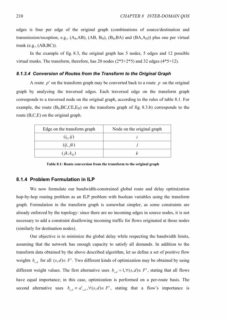
210 CHAPTER 8 INTER-DOMAIN QOS
edges is four per edge of the original graph (combinations of source/destination and
transmission/reception, e.g., (AS,AB), (AB, BD), (BS,BA) and (BA,AD)) plus one per virtual
trunk (e.g., (AB,BC)).
In the example of fig. 8.3, the original graph has 5 nodes, 5 edges and 12 possible
virtual trunks. The transform, therefore, has 20 nodes (2*5+2*5) and 32 edges (4*5+12).
8.1.3.4 Conversion of Routes from the Transform to the Original Graph
A route 'p on the transform graph may be converted back to a route p on the original
graph by analyzing the traversed edges. Each traversed edge on the transform graph
corresponds to a traversed node on the original graph, according to the rules of table 8.1. For
example, the route (BS,BC,CE,ED) on the transform graph of fig. 8.3.b) corresponds to the
route (B,C,E) on the original graph.
8.1.4 Problem Formulation in ILP
We now formulate our bandwidth-constrained global route and delay optimization
hop-by-hop routing problem as an ILP problem with boolean variables using the transform
graph. Formulation in the transform graph is somewhat simpler, as some constraints are
already enforced by the topology: since there are no incoming edges in source nodes, it is not
necessary to add a constraint disallowing incoming traffic for flows originated at those nodes
(similarly for destination nodes).
Our objective is to minimize the global delay while respecting the bandwidth limits,
assuming that the network has enough capacity to satisfy all demands. In addition to the
transform data obtained by the above described algorithm, let us define a set of positive flow
weights dsb , for all '),( Fds ∈ . Two different kinds of optimization may be obtained by using
different weight values. The first alternative uses '),(,1, Fdsb ds ∈∀= , stating that all flows
have equal importance; in this case, optimization is performed on a per-route basis. The
second alternative uses '),(,' ,, Fdsab dsds ∈∀∝ , stating that a flow’s importance is
Edge on the transform graph Node on the original graph
),( S iji i
),( jkij j
),( Dkjk k
Table 8.1: Route conversion from the transform to the original graph

8.1 INTER-DOMAIN QOS ROUTING WITH VIRTUAL TRUNKS 211
proportional to its traffic demand; in this case, optimization is performed on a traffic volume
basis.
Let us define the boolean decision variables sd
ijx which take the value 1 if the flow
'),( Fds ∈ is routed through the edge '),( Eji ∈ and the value 0 otherwise.
The problem can, thus, be formulated as follows:
Minimize ∑ ∑∈ ∈'),( '),(
,,,, '
Eji Fds
ds
jijids xwb subject to
{ } '),(,'),(,1,0,, EjiFdsx ds
ji ∈∈∀∈ (8.1)
'),(,'' ,'),(
,,, Ejicxa ji
Fds
ds
jids ∈∀≤∑∈
(8.2)
{ }( )dsVjFdsxxEji
ds
ji
Ekj
ds
kj ,','),(,0'),(
,,
'),(
,, −∈∈∀=− ∑∑
∈∈
(8.3)
'),(,1'),(
,, Fdsx
Ejs
ds
js ∈∀=∑∈
(8.4)
'),(,1'),(
,, Fdsx
Edi
ds
di ∈∀=∑∈
(8.5)
'),(:,'),(,'),(:'
,,
,, EisSiFdsxSx
EjiVjdtSt
ds
is
dt
ji ∈∈∈∀⋅≤∑ ∑∈∈
≠∈
(8.6)
∑ ∑ ∑ ∑∈∈
≠∈ ∈∈
≠∈
∈∀='),(:'),( '),(:'
,,
,, ,
EdjEjidsSs EdjVj
dsSs
ds
dj
ds
ji Ddxx (8.7)
Constraint set (8.1) imposes boolean decision variables, meaning that flows cannot be
split over multiple paths.
Constraint set (8.2) states that the sum of all flows traversing an edge will not exceed
its capacity.
Constraint sets (8.3), (8.4) and (8.5) are the “mass balance” equations: (8.3) means
that each flow entering a node that is neither source nor destination for that flow must leave it
and vice-versa; (8.4) means that each flow leaves the source node once and, similarly, (8.5)
means that each flow enters the destination node once.
Constraint set (8.6) means that if a flow from a source to a destination traverses a
given virtual node directly connected to that source, no other flows to the same destination
may traverse a different virtual node connected to the same source. On the original graph it
means that if the flow from a given node to a certain destination leaves that node by a given
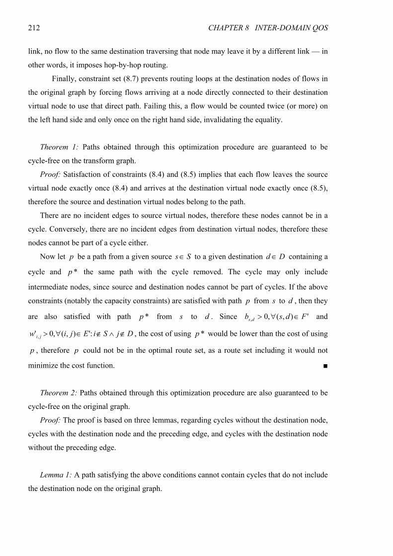
212 CHAPTER 8 INTER-DOMAIN QOS
link, no flow to the same destination traversing that node may leave it by a different link — in
other words, it imposes hop-by-hop routing.
Finally, constraint set (8.7) prevents routing loops at the destination nodes of flows in
the original graph by forcing flows arriving at a node directly connected to their destination
virtual node to use that direct path. Failing this, a flow would be counted twice (or more) on
the left hand side and only once on the right hand side, invalidating the equality.
Theorem 1: Paths obtained through this optimization procedure are guaranteed to be
cycle-free on the transform graph.
Proof: Satisfaction of constraints (8.4) and (8.5) implies that each flow leaves the source
virtual node exactly once (8.4) and arrives at the destination virtual node exactly once (8.5),
therefore the source and destination virtual nodes belong to the path.
There are no incident edges to source virtual nodes, therefore these nodes cannot be in a
cycle. Conversely, there are no incident edges from destination virtual nodes, therefore these
nodes cannot be part of a cycle either.
Now let p be a path from a given source Ss ∈ to a given destination Dd ∈ containing a
cycle and *p the same path with the cycle removed. The cycle may only include
intermediate nodes, since source and destination nodes cannot be part of cycles. If the above
constraints (notably the capacity constraints) are satisfied with path p from s to d , then they
are also satisfied with path *p from s to d . Since '),(,0, Fdsb ds ∈∀> and
DjSiEjiw ji ∉∧∉∈∀> :'),(,0' , , the cost of using *p would be lower than the cost of using
p , therefore p could not be in the optimal route set, as a route set including it would not
minimize the cost function. ■
Theorem 2: Paths obtained through this optimization procedure are also guaranteed to be
cycle-free on the original graph.
Proof: The proof is based on three lemmas, regarding cycles without the destination node,
cycles with the destination node and the preceding edge, and cycles with the destination node
without the preceding edge.
Lemma 1: A path satisfying the above conditions cannot contain cycles that do not include
the destination node on the original graph.

8.1 INTER-DOMAIN QOS ROUTING WITH VIRTUAL TRUNKS 213
Proof: Let 1p be a path on the original graph from source s to destination d containing a
cycle that does not include node d , and 1'p the equivalent path in the transform graph. Since
the cycle on 1p does not contain the destination d , it must contain a node i left by the flow
twice by different edges, ),( ji towards the cycle and ),( ki towards the destination node.
Therefore, in the transform graph, 1'p must contain virtual nodes ij and ik . Constraint (8.6)
implies that 1,, =di
jix and 1,, =di
kix . However, this violates constraint (8.4); therefore 1p can
only contain cycles that include the destination node d . ■
Lemma 2: A path satisfying the above conditions cannot contain cycles that include the
destination node and the preceding edge on the original graph.
Proof: Let 2p be a path on the original graph from source s to destination d containing a
cycle that contains node d and the edge incident to d , ),( di ; let 2'p be the equivalent path
in the transform graph. In this case, the flow enters d twice by the edge ),( di , from the
source and from the cycle. Therefore, in the transform graph, 2'p encloses a cycle containing
the virtual node id . This contradicts theorem 1, which states that 2'p is guaranteed to be
cycle-free on the transform graph, meaning that a cycle containing node d and the edge
incident to d cannot exist in the returned route set. ■
Lemma 3: A path satisfying the above conditions cannot contain cycles that include the
destination node but not the preceding edge on the original graph.
Proof: Let 3p be a path on the original graph from source s to destination d containing a
cycle that includes node d but not the edge incident to d ; let 3'p be the equivalent path in
the transform graph. In this case, the flow enters node d twice by different edges, ),( di and
),( dj , from the source and from the cycle. Therefore, in the transform graph, 3'p contains
virtual nodes id and jd , contributing two units to the left hand side of constraint (8.7).
According to constraint (8.5), the destination virtual node can only be entered once, therefore
this flow’s contribution to the right hand side of constraint (8.7) can only be one unit. Since
the same applies to all flows, no flow on the original graph can have a cycle containing the
destination node d but not the edge incident to d . ■
The preceding lemmas cover all possible cycles on the original graph, therefore all
paths satisfying the above conditions are guaranteed to be cycle-free on the original graph. ■
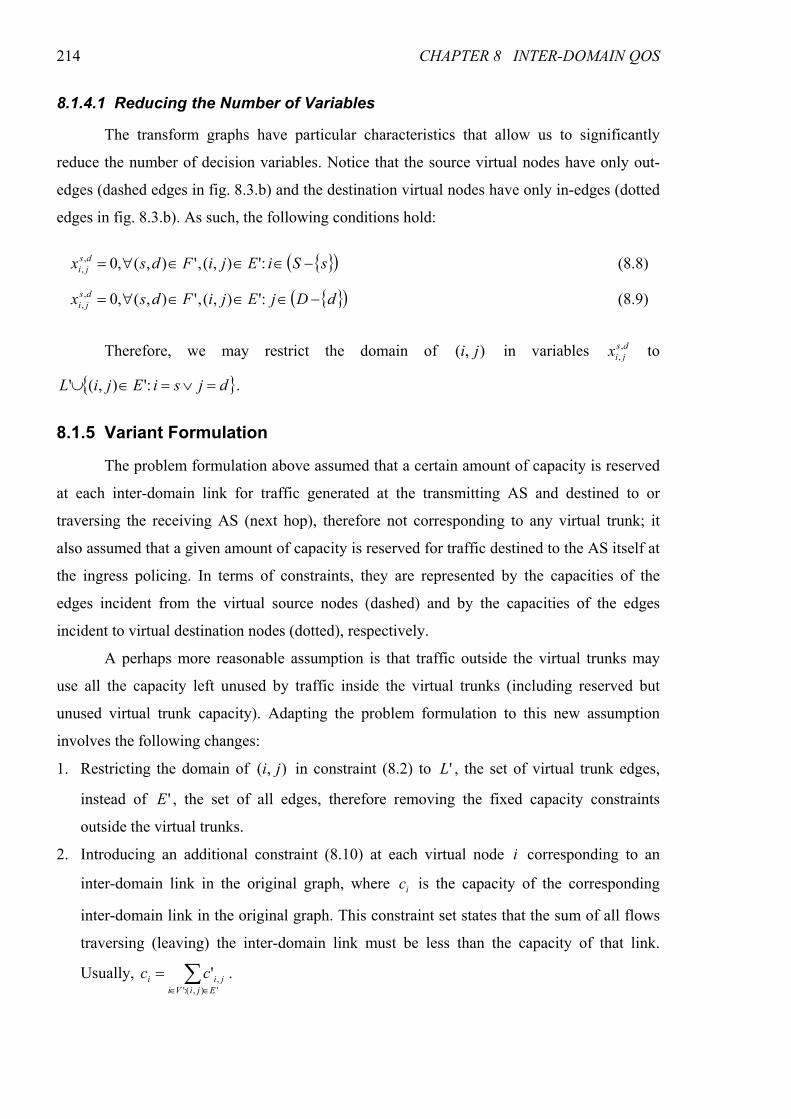
214 CHAPTER 8 INTER-DOMAIN QOS
8.1.4.1 Reducing the Number of Variables
The transform graphs have particular characteristics that allow us to significantly
reduce the number of decision variables. Notice that the source virtual nodes have only out-
edges (dashed edges in fig. 8.3.b) and the destination virtual nodes have only in-edges (dotted
edges in fig. 8.3.b). As such, the following conditions hold:
{ }( )sSiEjiFdsx ds
ji −∈∈∈∀= :'),(,'),(,0,, (8.8)
{ }( )dDjEjiFdsx ds
ji −∈∈∈∀= :'),(,'),(,0,, (8.9)
Therefore, we may restrict the domain of ),( ji in variables ds
jix,, to
{ }djsiEjiL =∨=∈∪ :'),(' .
8.1.5 Variant Formulation
The problem formulation above assumed that a certain amount of capacity is reserved
at each inter-domain link for traffic generated at the transmitting AS and destined to or
traversing the receiving AS (next hop), therefore not corresponding to any virtual trunk; it
also assumed that a given amount of capacity is reserved for traffic destined to the AS itself at
the ingress policing. In terms of constraints, they are represented by the capacities of the
edges incident from the virtual source nodes (dashed) and by the capacities of the edges
incident to virtual destination nodes (dotted), respectively.
A perhaps more reasonable assumption is that traffic outside the virtual trunks may
use all the capacity left unused by traffic inside the virtual trunks (including reserved but
unused virtual trunk capacity). Adapting the problem formulation to this new assumption
involves the following changes:
1. Restricting the domain of ),( ji in constraint (8.2) to 'L , the set of virtual trunk edges,
instead of 'E , the set of all edges, therefore removing the fixed capacity constraints
outside the virtual trunks.
2. Introducing an additional constraint (8.10) at each virtual node i corresponding to an
inter-domain link in the original graph, where ic is the capacity of the corresponding
inter-domain link in the original graph. This constraint set states that the sum of all flows
traversing (leaving) the inter-domain link must be less than the capacity of that link.
Usually, ∑∈∈
='),(:','
EjiVi
jii cc .
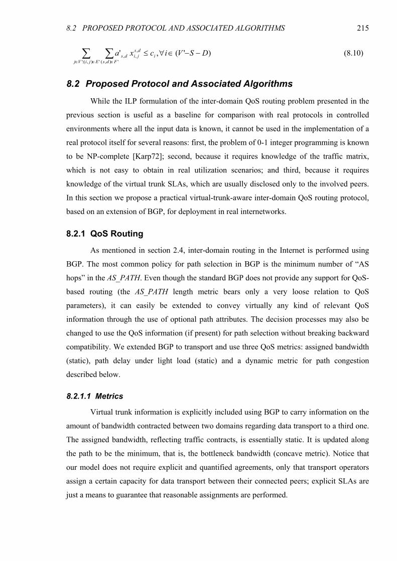
8.2 PROPOSED PROTOCOL AND ASSOCIATED ALGORITHMS 215
)'(,''),(:' '),(
,,, DSVicxa i
EjiVj Fds
ds
jids −−∈∀≤∑ ∑∈∈ ∈
(8.10)
8.2 Proposed Protocol and Associated Algorithms
While the ILP formulation of the inter-domain QoS routing problem presented in the
previous section is useful as a baseline for comparison with real protocols in controlled
environments where all the input data is known, it cannot be used in the implementation of a
real protocol itself for several reasons: first, the problem of 0-1 integer programming is known
to be NP-complete [Karp72]; second, because it requires knowledge of the traffic matrix,
which is not easy to obtain in real utilization scenarios; and third, because it requires
knowledge of the virtual trunk SLAs, which are usually disclosed only to the involved peers.
In this section we propose a practical virtual-trunk-aware inter-domain QoS routing protocol,
based on an extension of BGP, for deployment in real internetworks.
8.2.1 QoS Routing
As mentioned in section 2.4, inter-domain routing in the Internet is performed using
BGP. The most common policy for path selection in BGP is the minimum number of “AS
hops” in the AS_PATH. Even though the standard BGP does not provide any support for QoS-
based routing (the AS_PATH length metric bears only a very loose relation to QoS
parameters), it can easily be extended to convey virtually any kind of relevant QoS
information through the use of optional path attributes. The decision processes may also be
changed to use the QoS information (if present) for path selection without breaking backward
compatibility. We extended BGP to transport and use three QoS metrics: assigned bandwidth
(static), path delay under light load (static) and a dynamic metric for path congestion
described below.
8.2.1.1 Metrics
Virtual trunk information is explicitly included using BGP to carry information on the
amount of bandwidth contracted between two domains regarding data transport to a third one.
The assigned bandwidth, reflecting traffic contracts, is essentially static. It is updated along
the path to be the minimum, that is, the bottleneck bandwidth (concave metric). Notice that
our model does not require explicit and quantified agreements, only that transport operators
assign a certain capacity for data transport between their connected peers; explicit SLAs are
just a means to guarantee that reasonable assignments are performed.
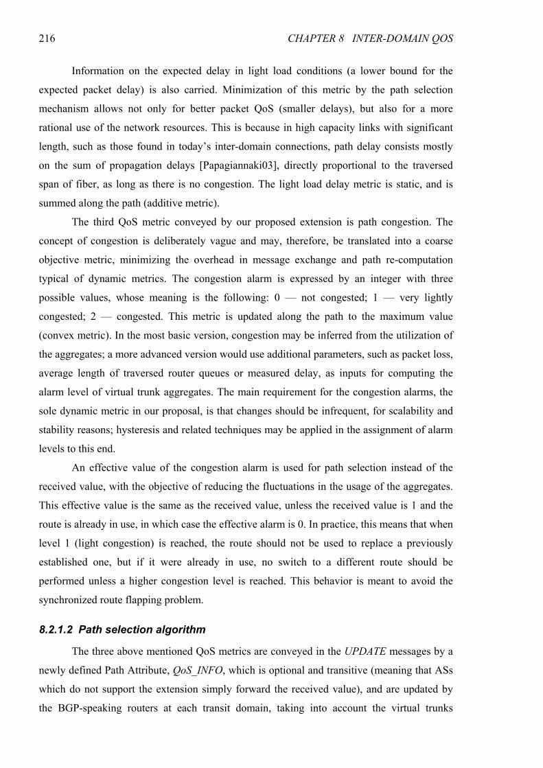
216 CHAPTER 8 INTER-DOMAIN QOS
Information on the expected delay in light load conditions (a lower bound for the
expected packet delay) is also carried. Minimization of this metric by the path selection
mechanism allows not only for better packet QoS (smaller delays), but also for a more
rational use of the network resources. This is because in high capacity links with significant
length, such as those found in today’s inter-domain connections, path delay consists mostly
on the sum of propagation delays [Papagiannaki03], directly proportional to the traversed
span of fiber, as long as there is no congestion. The light load delay metric is static, and is
summed along the path (additive metric).
The third QoS metric conveyed by our proposed extension is path congestion. The
concept of congestion is deliberately vague and may, therefore, be translated into a coarse
objective metric, minimizing the overhead in message exchange and path re-computation
typical of dynamic metrics. The congestion alarm is expressed by an integer with three
possible values, whose meaning is the following: 0 — not congested; 1 — very lightly
congested; 2 — congested. This metric is updated along the path to the maximum value
(convex metric). In the most basic version, congestion may be inferred from the utilization of
the aggregates; a more advanced version would use additional parameters, such as packet loss,
average length of traversed router queues or measured delay, as inputs for computing the
alarm level of virtual trunk aggregates. The main requirement for the congestion alarms, the
sole dynamic metric in our proposal, is that changes should be infrequent, for scalability and
stability reasons; hysteresis and related techniques may be applied in the assignment of alarm
levels to this end.
An effective value of the congestion alarm is used for path selection instead of the
received value, with the objective of reducing the fluctuations in the usage of the aggregates.
This effective value is the same as the received value, unless the received value is 1 and the
route is already in use, in which case the effective alarm is 0. In practice, this means that when
level 1 (light congestion) is reached, the route should not be used to replace a previously
established one, but if it were already in use, no switch to a different route should be
performed unless a higher congestion level is reached. This behavior is meant to avoid the
synchronized route flapping problem.
8.2.1.2 Path selection algorithm
The three above mentioned QoS metrics are conveyed in the UPDATE messages by a
newly defined Path Attribute, QoS_INFO, which is optional and transitive (meaning that ASs
which do not support the extension simply forward the received value), and are updated by
the BGP-speaking routers at each transit domain, taking into account the virtual trunks
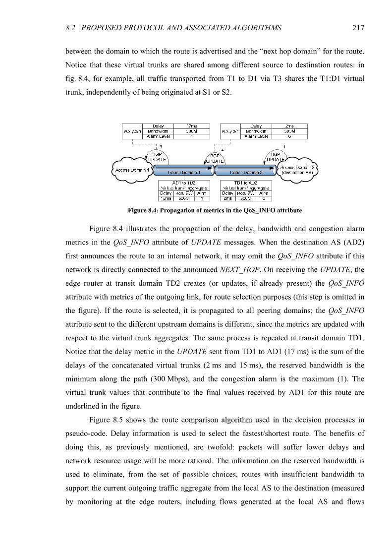
8.2 PROPOSED PROTOCOL AND ASSOCIATED ALGORITHMS 217
between the domain to which the route is advertised and the “next hop domain” for the route.
Notice that these virtual trunks are shared among different source to destination routes: in
fig. 8.4, for example, all traffic transported from T1 to D1 via T3 shares the T1:D1 virtual
trunk, independently of being originated at S1 or S2.
Figure 8.4 illustrates the propagation of the delay, bandwidth and congestion alarm
metrics in the QoS_INFO attribute of UPDATE messages. When the destination AS (AD2)
first announces the route to an internal network, it may omit the QoS_INFO attribute if this
network is directly connected to the announced NEXT_HOP. On receiving the UPDATE, the
edge router at transit domain TD2 creates (or updates, if already present) the QoS_INFO
attribute with metrics of the outgoing link, for route selection purposes (this step is omitted in
the figure). If the route is selected, it is propagated to all peering domains; the QoS_INFO
attribute sent to the different upstream domains is different, since the metrics are updated with
respect to the virtual trunk aggregates. The same process is repeated at transit domain TD1.
Notice that the delay metric in the UPDATE sent from TD1 to AD1 (17 ms) is the sum of the
delays of the concatenated virtual trunks (2 ms and 15 ms), the reserved bandwidth is the
minimum along the path (300 Mbps), and the congestion alarm is the maximum (1). The
virtual trunk values that contribute to the final values received by AD1 for this route are
underlined in the figure.
Figure 8.5 shows the route comparison algorithm used in the decision processes in
pseudo-code. Delay information is used to select the fastest/shortest route. The benefits of
doing this, as previously mentioned, are twofold: packets will suffer lower delays and
network resource usage will be more rational. The information on the reserved bandwidth is
used to eliminate, from the set of possible choices, routes with insufficient bandwidth to
support the current outgoing traffic aggregate from the local AS to the destination (measured
by monitoring at the edge routers, including flows generated at the local AS and flows
Figure 8.4: Propagation of metrics in the QoS_INFO attribute
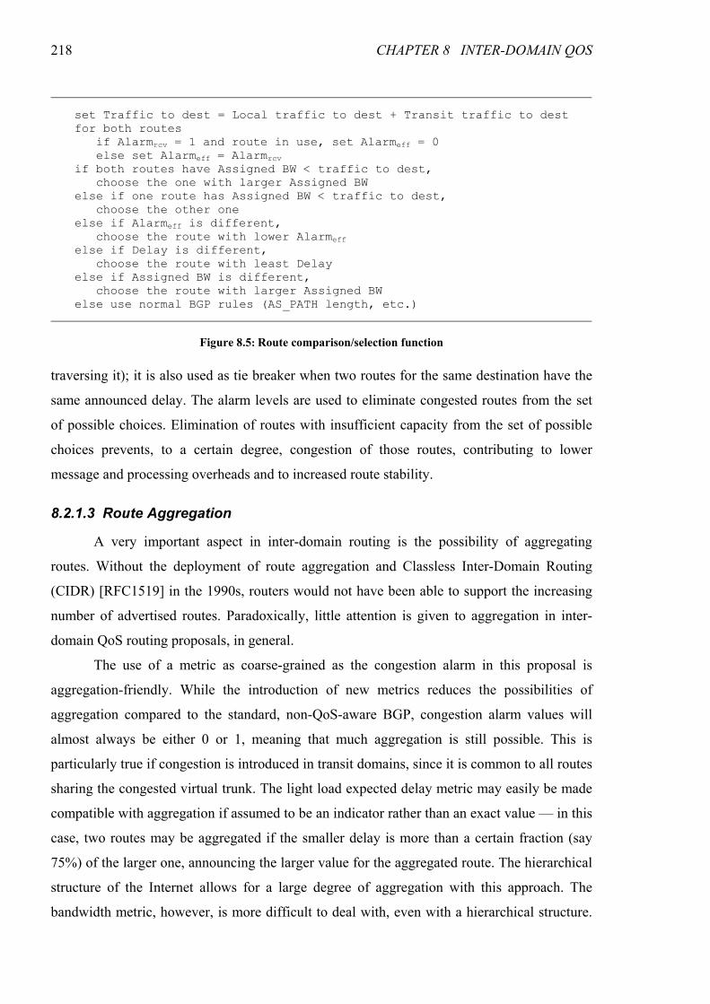
218 CHAPTER 8 INTER-DOMAIN QOS
traversing it); it is also used as tie breaker when two routes for the same destination have the
same announced delay. The alarm levels are used to eliminate congested routes from the set
of possible choices. Elimination of routes with insufficient capacity from the set of possible
choices prevents, to a certain degree, congestion of those routes, contributing to lower
message and processing overheads and to increased route stability.
8.2.1.3 Route Aggregation
A very important aspect in inter-domain routing is the possibility of aggregating
routes. Without the deployment of route aggregation and Classless Inter-Domain Routing
(CIDR) [RFC1519] in the 1990s, routers would not have been able to support the increasing
number of advertised routes. Paradoxically, little attention is given to aggregation in inter-
domain QoS routing proposals, in general.
The use of a metric as coarse-grained as the congestion alarm in this proposal is
aggregation-friendly. While the introduction of new metrics reduces the possibilities of
aggregation compared to the standard, non-QoS-aware BGP, congestion alarm values will
almost always be either 0 or 1, meaning that much aggregation is still possible. This is
particularly true if congestion is introduced in transit domains, since it is common to all routes
sharing the congested virtual trunk. The light load expected delay metric may easily be made
compatible with aggregation if assumed to be an indicator rather than an exact value — in this
case, two routes may be aggregated if the smaller delay is more than a certain fraction (say
75%) of the larger one, announcing the larger value for the aggregated route. The hierarchical
structure of the Internet allows for a large degree of aggregation with this approach. The
bandwidth metric, however, is more difficult to deal with, even with a hierarchical structure.
set Traffic to dest = Local traffic to dest + Transit traffic to dest for both routes if Alarmrcv = 1 and route in use, set Alarmeff = 0 else set Alarmeff = Alarmrcv if both routes have Assigned BW < traffic to dest, choose the one with larger Assigned BW else if one route has Assigned BW < traffic to dest, choose the other one else if Alarmeff is different, choose the route with lower Alarmeff else if Delay is different, choose the route with least Delay else if Assigned BW is different, choose the route with larger Assigned BW else use normal BGP rules (AS_PATH length, etc.)
Figure 8.5: Route comparison/selection function
8.3 SIMULATION RESULTS 219
Perhaps a solution to be deployed in the Internet at large would require the use of a very
coarsely grained bandwidth metric, or even entirely giving up the use of this metric. However,
a meaningful assessment of the tradeoff between the bandwidth metric and route aggregability
would require a much larger scale evaluation and access to information available only to data
transport operators, thus exceeding the scope of this thesis.
8.3 Simulation Results
In this section we present simulation results obtained in ns-2 [NS2] of the QoS_INFO
proposal for inter-domain QoS routing, implemented as an extension of an existing BGP
module [Feng04]. These results concern the performance, in terms of delay, loss probability
and inter-domain links congestion, of QoS_INFO when compared to standard BGP, to BGP
with the QoS_NLRI extension conveying static one-way delay information (the expected
delay of the route in light load conditions), and to optimal solutions obtained using the ILP
formulations of section 8.1 (both the original, opt-r, and the variant, opt-nr) in a MIP code
(Xpress-MP from Dash Optimization [DashOpt]). They also concern the number of updates
required to provide inter-domain QoS and the stability of the routes. Note that the QoS_NLRI
extension can be used to convey QoS parameters other than delay, and that the extension does
not specify whether the delay information is static or dynamic. In fact, [Cristallo04] is focused
on the BGP extension for the transport of QoS information, not specifying the way that
information is to be used by BGP in the path selection process. Therefore, in this comparison
we used the scenario therein illustrated.
The amount of traffic in inter-domain scenarios is extremely high, making it very
difficult to complete simulations with realistic parameters within a reasonable time span. For
this reason, in our implementation we have chosen to simulate the signaling protocol normally
at the packet level, but not the data traffic, which was mathematically simulated using the
well-known M/G/1 queuing model with three different packet sizes: 50% of packets with 40
bytes (representing 4% of the traffic volume), simulating SYN, ACK, FIN and RST TCP
segments; 20% of packets with 80 bytes, simulating packetized voice (3% of traffic volume);
and 30% of packets with 1500 bytes, simulating full size TCP segments (93% of traffic
volume). These packet sizes reflect the bimodality currently observed in internet traffic
[Sinha05], complemented with voice packets, whose frequency tends to increase. Queuing
delays were obtained using the Pollaczek-Khintchine formula [Bertsekas92],
[ ][ ]( )SE
SEWQ λ
λ−
=12
2
where WQ is the queuing delay, λ is the traffic arrival rate and S is the
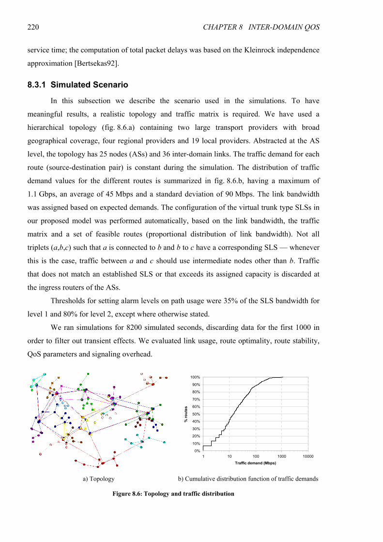
220 CHAPTER 8 INTER-DOMAIN QOS
service time; the computation of total packet delays was based on the Kleinrock independence
approximation [Bertsekas92].
8.3.1 Simulated Scenario
In this subsection we describe the scenario used in the simulations. To have
meaningful results, a realistic topology and traffic matrix is required. We have used a
hierarchical topology (fig. 8.6.a) containing two large transport providers with broad
geographical coverage, four regional providers and 19 local providers. Abstracted at the AS
level, the topology has 25 nodes (ASs) and 36 inter-domain links. The traffic demand for each
route (source-destination pair) is constant during the simulation. The distribution of traffic
demand values for the different routes is summarized in fig. 8.6.b, having a maximum of
1.1 Gbps, an average of 45 Mbps and a standard deviation of 90 Mbps. The link bandwidth
was assigned based on expected demands. The configuration of the virtual trunk type SLSs in
our proposed model was performed automatically, based on the link bandwidth, the traffic
matrix and a set of feasible routes (proportional distribution of link bandwidth). Not all
triplets (a,b,c) such that a is connected to b and b to c have a corresponding SLS — whenever
this is the case, traffic between a and c should use intermediate nodes other than b. Traffic
that does not match an established SLS or that exceeds its assigned capacity is discarded at
the ingress routers of the ASs.
Thresholds for setting alarm levels on path usage were 35% of the SLS bandwidth for
level 1 and 80% for level 2, except where otherwise stated.
We ran simulations for 8200 simulated seconds, discarding data for the first 1000 in
order to filter out transient effects. We evaluated link usage, route optimality, route stability,
QoS parameters and signaling overhead.
0%
10%
20%
30%
40%
50%
60%
70%
80%
90%
100%
1 10 100 1000 10000
Traffic demand (Mbps)
% routes
a) Topology b) Cumulative distribution function of traffic demands
Figure 8.6: Topology and traffic distribution
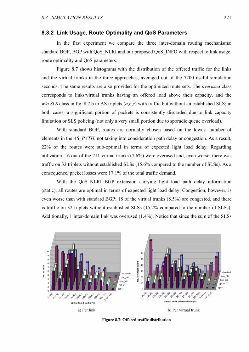
8.3 SIMULATION RESULTS 221
8.3.2 Link Usage, Route Optimality and QoS Parameters
In the first experiment we compare the three inter-domain routing mechanisms:
standard BGP, BGP with QoS_NLRI and our proposed QoS_INFO with respect to link usage,
route optimality and QoS parameters.
Figure 8.7 shows histograms with the distribution of the offered traffic for the links
and the virtual trunks in the three approaches, averaged out of the 7200 useful simulation
seconds. The same results are also provided for the optimized route sets. The overused class
corresponds to links/virtual trunks having an offered load above their capacity, and the
w/o SLS class in fig. 8.7.b to AS triplets (a,b,c) with traffic but without an established SLS; in
both cases, a significant portion of packets is consistently discarded due to link capacity
limitation or SLS policing (not only a very small portion due to sporadic queue overload).
With standard BGP, routes are normally chosen based on the lowest number of
elements in the AS_PATH, not taking into consideration path delay or congestion. As a result,
22% of the routes were sub-optimal in terms of expected light load delay. Regarding
utilization, 16 out of the 211 virtual trunks (7.6%) were overused and, even worse, there was
traffic on 33 triplets without established SLSs (15.6% compared to the number of SLSs). As a
consequence, packet losses were 17.1% of the total traffic demand.
With the QoS_NLRI BGP extension carrying light load path delay information
(static), all routes are optimal in terms of expected light load delay. Congestion, however, is
even worse than with standard BGP: 18 of the virtual trunks (8.5%) are congested, and there
is traffic on 32 triplets without established SLSs (15.2% compared to the number of SLSs).
Additionally, 1 inter-domain link was overused (1.4%). Notice that since the sum of the SLSs
0
2
4
6
8
10
12
14
16
18
20
No. of links
[0,10)
[10,20)
[20,30)
[30,40)
[40,50)
[50,60)
[60,70)
[70,80)
[80,90)
[90,100)
Overused
opt-r
opt-nr
qos_info
qos_nlri
standard
Link offered traffic (%)
0
10
20
30
40
50
60
No. of virtual trunks
[0,10)
[10,20)
[20,30)
[30,40)
[40,50)
[50,60)
[60,70)
[70,80)
[80,90)
[90,100)
Overused
w/o SLS
opt-r
opt-nr
qos_info
qos_nlri
standard
Virtual trunk offered traffic (%)
a) Per link b) Per virtual trunk
Figure 8.7: Offered traffic distribution
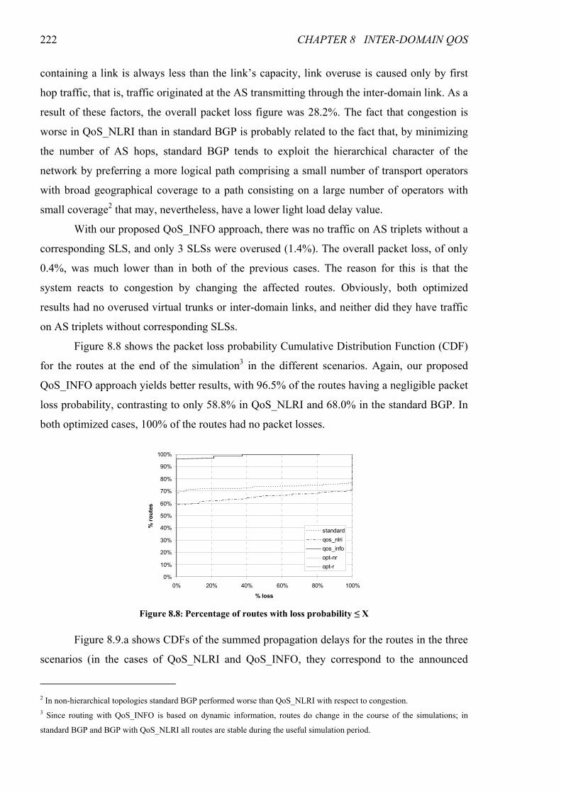
222 CHAPTER 8 INTER-DOMAIN QOS
containing a link is always less than the link’s capacity, link overuse is caused only by first
hop traffic, that is, traffic originated at the AS transmitting through the inter-domain link. As a
result of these factors, the overall packet loss figure was 28.2%. The fact that congestion is
worse in QoS_NLRI than in standard BGP is probably related to the fact that, by minimizing
the number of AS hops, standard BGP tends to exploit the hierarchical character of the
network by preferring a more logical path comprising a small number of transport operators
with broad geographical coverage to a path consisting on a large number of operators with
small coverage2 that may, nevertheless, have a lower light load delay value.
With our proposed QoS_INFO approach, there was no traffic on AS triplets without a
corresponding SLS, and only 3 SLSs were overused (1.4%). The overall packet loss, of only
0.4%, was much lower than in both of the previous cases. The reason for this is that the
system reacts to congestion by changing the affected routes. Obviously, both optimized
results had no overused virtual trunks or inter-domain links, and neither did they have traffic
on AS triplets without corresponding SLSs.
Figure 8.8 shows the packet loss probability Cumulative Distribution Function (CDF)
for the routes at the end of the simulation3 in the different scenarios. Again, our proposed
QoS_INFO approach yields better results, with 96.5% of the routes having a negligible packet
loss probability, contrasting to only 58.8% in QoS_NLRI and 68.0% in the standard BGP. In
both optimized cases, 100% of the routes had no packet losses.
Figure 8.9.a shows CDFs of the summed propagation delays for the routes in the three
scenarios (in the cases of QoS_NLRI and QoS_INFO, they correspond to the announced
2 In non-hierarchical topologies standard BGP performed worse than QoS_NLRI with respect to congestion. 3 Since routing with QoS_INFO is based on dynamic information, routes do change in the course of the simulations; in
standard BGP and BGP with QoS_NLRI all routes are stable during the useful simulation period.
0%
10%
20%
30%
40%
50%
60%
70%
80%
90%
100%
0% 20% 40% 60% 80% 100%
% loss
% routes
standard
qos_nlri
qos_info
opt-nr
opt-r
Figure 8.8: Percentage of routes with loss probability ≤ X
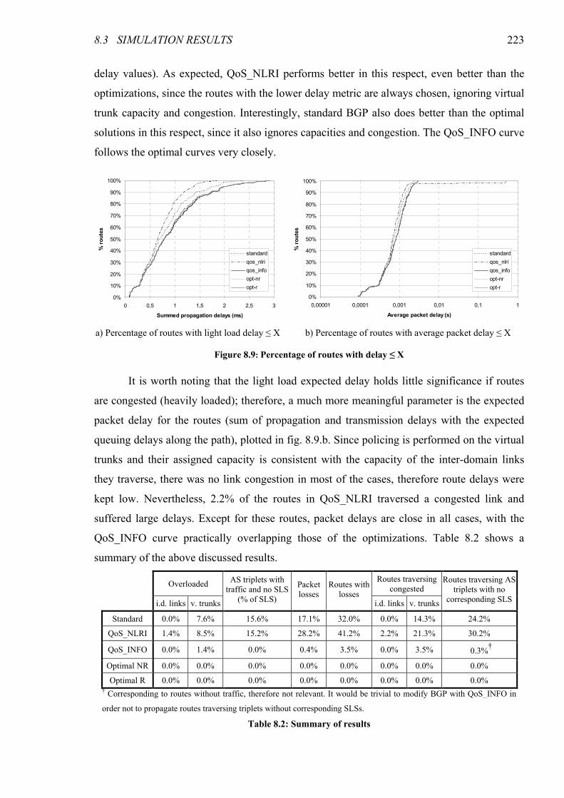
8.3 SIMULATION RESULTS 223
delay values). As expected, QoS_NLRI performs better in this respect, even better than the
optimizations, since the routes with the lower delay metric are always chosen, ignoring virtual
trunk capacity and congestion. Interestingly, standard BGP also does better than the optimal
solutions in this respect, since it also ignores capacities and congestion. The QoS_INFO curve
follows the optimal curves very closely.
It is worth noting that the light load expected delay holds little significance if routes
are congested (heavily loaded); therefore, a much more meaningful parameter is the expected
packet delay for the routes (sum of propagation and transmission delays with the expected
queuing delays along the path), plotted in fig. 8.9.b. Since policing is performed on the virtual
trunks and their assigned capacity is consistent with the capacity of the inter-domain links
they traverse, there was no link congestion in most of the cases, therefore route delays were
kept low. Nevertheless, 2.2% of the routes in QoS_NLRI traversed a congested link and
suffered large delays. Except for these routes, packet delays are close in all cases, with the
QoS_INFO curve practically overlapping those of the optimizations. Table 8.2 shows a
summary of the above discussed results.
0%
10%
20%
30%
40%
50%
60%
70%
80%
90%
100%
0 0,5 1 1,5 2 2,5 3
Summed propagation delays (ms)
% routes
standard
qos_nlri
qos_info
opt-nr
opt-r
0%
10%
20%
30%
40%
50%
60%
70%
80%
90%
100%
0,00001 0,0001 0,001 0,01 0,1 1
Average packet delay (s)
% routes
standard
qos_nlri
qos_info
opt-nr
opt-r
a) Percentage of routes with light load delay ≤ X b) Percentage of routes with average packet delay ≤ X
Figure 8.9: Percentage of routes with delay ≤ X
Overloaded Routes traversing
congested
i.d. links v. trunks
AS triplets with traffic and no SLS
(% of SLS)
Packet losses
Routes with losses
i.d. links v. trunks
Routes traversing AS triplets with no
corresponding SLS
Standard 0.0% 7.6% 15.6% 17.1% 32.0% 0.0% 14.3% 24.2%
QoS_NLRI 1.4% 8.5% 15.2% 28.2% 41.2% 2.2% 21.3% 30.2%
QoS_INFO 0.0% 1.4% 0.0% 0.4% 3.5% 0.0% 3.5% †0.3%
†
Optimal NR 0.0% 0.0% 0.0% 0.0% 0.0% 0.0% 0.0% 0.0%
Optimal R 0.0% 0.0% 0.0% 0.0% 0.0% 0.0% 0.0% 0.0% † Corresponding to routes without traffic, therefore not relevant. It would be trivial to modify BGP with QoS_INFO in
order not to propagate routes traversing triplets without corresponding SLSs.
Table 8.2: Summary of results
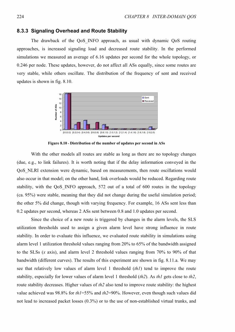
224 CHAPTER 8 INTER-DOMAIN QOS
8.3.3 Signaling Overhead and Route Stability
The drawback of the QoS_INFO approach, as usual with dynamic QoS routing
approaches, is increased signaling load and decreased route stability. In the performed
simulations we measured an average of 6.16 updates per second for the whole topology, or
0.246 per node. These updates, however, do not affect all ASs equally, since some routes are
very stable, while others oscillate. The distribution of the frequency of sent and received
updates is shown in fig. 8.10.
With the other models all routes are stable as long as there are no topology changes
(due, e.g., to link failures). It is worth noting that if the delay information conveyed in the
QoS_NLRI extension were dynamic, based on measurements, then route oscillations would
also occur in that model; on the other hand, link overloads would be reduced. Regarding route
stability, with the QoS_INFO approach, 572 out of a total of 600 routes in the topology
(ca. 95%) were stable, meaning that they did not change during the useful simulation period;
the other 5% did change, though with varying frequency. For example, 16 ASs sent less than
0.2 updates per second, whereas 2 ASs sent between 0.8 and 1.0 updates per second.
Since the choice of a new route is triggered by changes in the alarm levels, the SLS
utilization thresholds used to assign a given alarm level have strong influence in route
stability. In order to evaluate this influence, we evaluated route stability in simulations using
alarm level 1 utilization threshold values ranging from 20% to 65% of the bandwidth assigned
to the SLSs (x axis), and alarm level 2 threshold values ranging from 70% to 90% of that
bandwidth (different curves). The results of this experiment are shown in fig. 8.11.a. We may
see that relatively low values of alarm level 1 threshold (th1) tend to improve the route
stability, especially for lower values of alarm level 1 threshold (th2). As th1 gets close to th2,
route stability decreases. Higher values of th2 also tend to improve route stability: the highest
value achieved was 98.8% for th1=55% and th2=90%. However, even though such values did
not lead to increased packet losses (0.3%) or to the use of non-established virtual trunks, and
0
2
4
6
8
10
12
14
16
Number of ASs
[0.0,0.2) [0.2,0.4) [0.4,0.6) [0.6,0.8) [0.8,1.0) [1.0,1.2) [1.2,1.4) [1.4,1.6) [1.6,1.8) [1.8,2.0)
Updates per second
Sent
Received
Figure 8.10 - Distribution of the number of updates per second in ASs
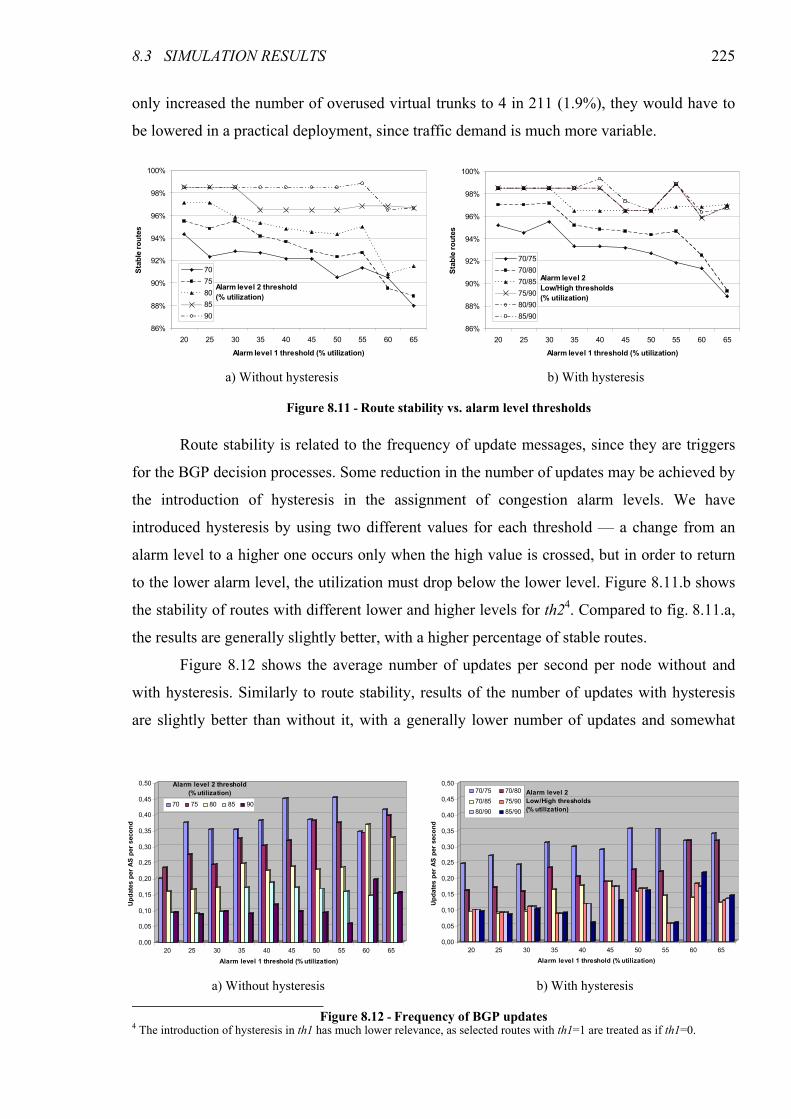
8.3 SIMULATION RESULTS 225
only increased the number of overused virtual trunks to 4 in 211 (1.9%), they would have to
be lowered in a practical deployment, since traffic demand is much more variable.
Route stability is related to the frequency of update messages, since they are triggers
for the BGP decision processes. Some reduction in the number of updates may be achieved by
the introduction of hysteresis in the assignment of congestion alarm levels. We have
introduced hysteresis by using two different values for each threshold — a change from an
alarm level to a higher one occurs only when the high value is crossed, but in order to return
to the lower alarm level, the utilization must drop below the lower level. Figure 8.11.b shows
the stability of routes with different lower and higher levels for th24. Compared to fig. 8.11.a,
the results are generally slightly better, with a higher percentage of stable routes.
Figure 8.12 shows the average number of updates per second per node without and
with hysteresis. Similarly to route stability, results of the number of updates with hysteresis
are slightly better than without it, with a generally lower number of updates and somewhat
4 The introduction of hysteresis in th1 has much lower relevance, as selected routes with th1=1 are treated as if th1=0.
86%
88%
90%
92%
94%
96%
98%
100%
20 25 30 35 40 45 50 55 60 65
Alarm level 1 threshold (% utilization)
Stable routes
70
75
80
85
90
Alarm level 2 threshold(% utilization)
86%
88%
90%
92%
94%
96%
98%
100%
20 25 30 35 40 45 50 55 60 65
Alarm level 1 threshold (% utilization)
Stable routes
70/75
70/80
70/85
75/90
80/90
85/90
Alarm level 2Low/High thresholds(% utilization)
a) Without hysteresis b) With hysteresis Figure 8.11 - Route stability vs. alarm level thresholds
0,00
0,05
0,10
0,15
0,20
0,25
0,30
0,35
0,40
0,45
0,50
Updates per AS per second
20 25 30 35 40 45 50 55 60 65
Alarm level 1 threshold (% utilization)
70 75 80 85 90
Alarm level 2 threshold(% utilization)
0,00
0,05
0,10
0,15
0,20
0,25
0,30
0,35
0,40
0,45
0,50
Updates per AS per second
20 25 30 35 40 45 50 55 60 65
Alarm level 1 threshold (% utilization)
70/75 70/80
70/85 75/90
80/90 85/90
Alarm level 2Low/High thresholds(% utilization)
a) Without hysteresis b) With hysteresis
Figure 8.12 - Frequency of BGP updates
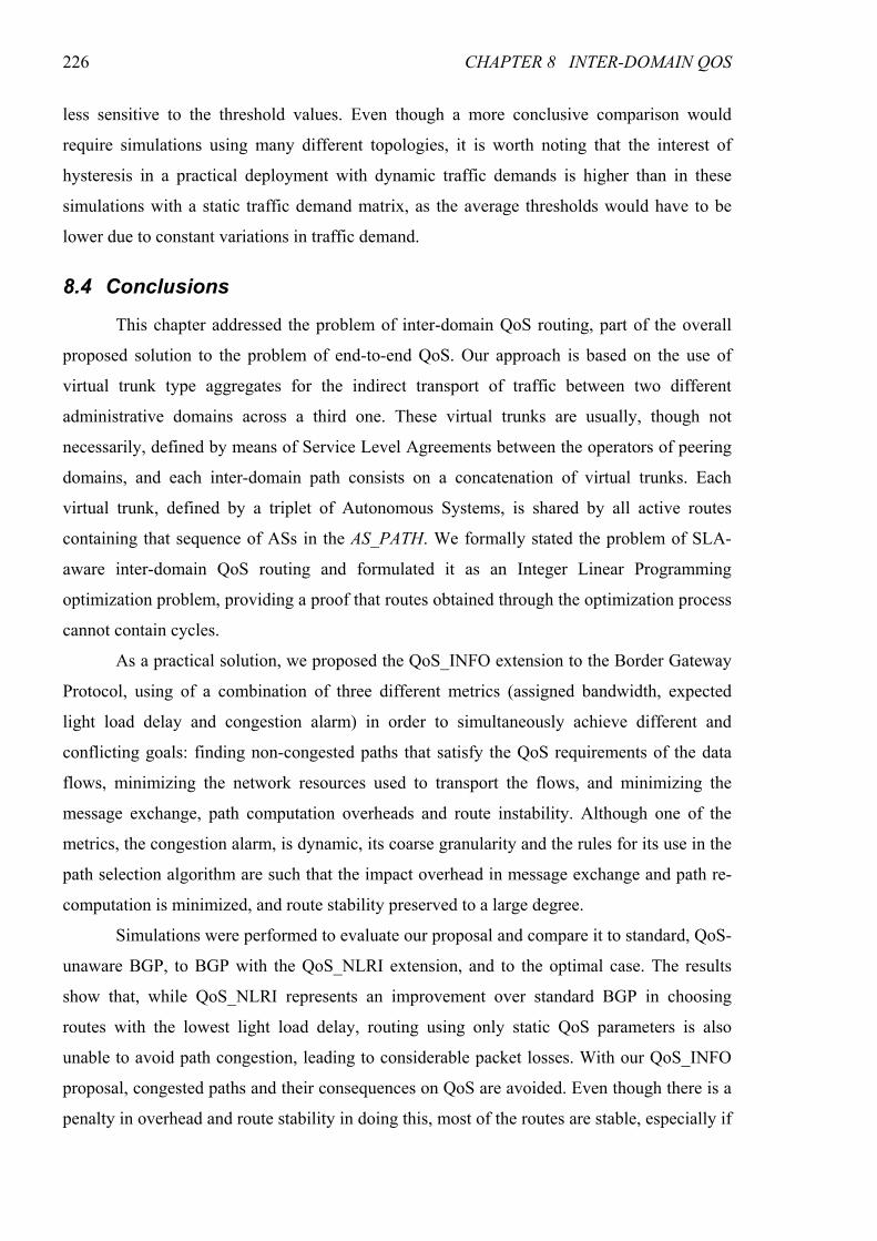
226 CHAPTER 8 INTER-DOMAIN QOS
less sensitive to the threshold values. Even though a more conclusive comparison would
require simulations using many different topologies, it is worth noting that the interest of
hysteresis in a practical deployment with dynamic traffic demands is higher than in these
simulations with a static traffic demand matrix, as the average thresholds would have to be
lower due to constant variations in traffic demand.
8.4 Conclusions
This chapter addressed the problem of inter-domain QoS routing, part of the overall
proposed solution to the problem of end-to-end QoS. Our approach is based on the use of
virtual trunk type aggregates for the indirect transport of traffic between two different
administrative domains across a third one. These virtual trunks are usually, though not
necessarily, defined by means of Service Level Agreements between the operators of peering
domains, and each inter-domain path consists on a concatenation of virtual trunks. Each
virtual trunk, defined by a triplet of Autonomous Systems, is shared by all active routes
containing that sequence of ASs in the AS_PATH. We formally stated the problem of SLA-
aware inter-domain QoS routing and formulated it as an Integer Linear Programming
optimization problem, providing a proof that routes obtained through the optimization process
cannot contain cycles.
As a practical solution, we proposed the QoS_INFO extension to the Border Gateway
Protocol, using of a combination of three different metrics (assigned bandwidth, expected
light load delay and congestion alarm) in order to simultaneously achieve different and
conflicting goals: finding non-congested paths that satisfy the QoS requirements of the data
flows, minimizing the network resources used to transport the flows, and minimizing the
message exchange, path computation overheads and route instability. Although one of the
metrics, the congestion alarm, is dynamic, its coarse granularity and the rules for its use in the
path selection algorithm are such that the impact overhead in message exchange and path re-
computation is minimized, and route stability preserved to a large degree.
Simulations were performed to evaluate our proposal and compare it to standard, QoS-
unaware BGP, to BGP with the QoS_NLRI extension, and to the optimal case. The results
show that, while QoS_NLRI represents an improvement over standard BGP in choosing
routes with the lowest light load delay, routing using only static QoS parameters is also
unable to avoid path congestion, leading to considerable packet losses. With our QoS_INFO
proposal, congested paths and their consequences on QoS are avoided. Even though there is a
penalty in overhead and route stability in doing this, most of the routes are stable, especially if

8.4 CONCLUSIONS 227
the thresholds for alarm setting are appropriately selected. The introduction of hysteresis in
the alarm level assignment seems to improve stability and overhead, and is expected to have
an even higher relevance in a real deployment of the protocol, with dynamic traffic demands.

229
CHAPTER 9
CONCLUSIONS
This thesis dealt with the problem of scalable QoS provisioning in packet switching
networks, and involved work on many different subjects (low level architectural issues,
algorithms, signaling, etc.). This chapter concludes the dissertation with a summary of the
work done and our main results, and with an identification of open problems that could be
used as a starting point for further research in these areas.
9.1 Thesis Summary
The work presented in the previous chapters had two main parts, corresponding to two
different lines of our research. The first line concerned distributed models for providing end-
to-end QoS in the Internet, where the routers along the path of the flows autonomously
perform both data plane and control plane functions. The second line of research concerned
the QoS subsystem of a next-generation IP-based mobile telecommunications network
architecture, more specifically the one proposed in the DAIDALOS Integrating Project, in the
scope of which the second part of our work was performed.
In the first part, we started by performing an evaluation of the RSVP Reservation
Aggregation model for scalable QoS provisioning in high-speed backbone networks. We gave
an overview of the model and of our implementation in the ns-2 simulator, which required the
definition of a policy for aggregate bandwidth management, not provided by the standard.
Simulation results have shown that the RSVP Aggregation model can provide RSVP/IntServ
Controlled Load service semantics but, contrary to the latter, in a scalable fashion. Packet
230 CHAPTER 9 CONCLUSIONS
classification and scheduling are performed per class, based on the DiffServ framework, and
the signaling load is greatly reduced — even with a small test topology, the signaling load
was reduced to less than 1/10th that of RSVP/IntServ. The simulation results have also shown
the existence of a tradeoff between signaling load reduction and lower network utilization:
holding more unused capacity in an aggregate increases the probability that new flows can be
accepted into that aggregate without signaling the core nodes, but also increases the
probability that bandwidth increases in other aggregates, necessary to accept new flows in
those aggregates, are rejected, thus reducing network utilization. The operating point in this
tradeoff is defined by setting two tunable parameters of the bandwidth management policy —
the bulk size and the hysteresis time.
With the goals of providing scalable end-to-end QoS with higher resource utilization
than with RSVP Aggregation and an additional service class with stricter guarantees than
Controlled Load, we proposed the Scalable Reservation-Based QoS (SRBQ) architecture, a
model where scalability is achieved by using exclusively low computational complexity
algorithms whose execution time is independent on the number of simultaneous flows. SRBQ
provides two service classes: the Guaranteed Service class, with strict QoS guarantees, and a
Controlled Load class, providing only soft guarantees but more tolerant to burstiness. It
combines the use of DiffServ style per class aggregation on the data plane (packet
classification, scheduling, policing and shaping) with a scalable signaling model for per-flow
resource reservation. Some techniques were developed for making per-flow resource
reservation signaling scale to a very large number of simultaneous flows, namely a label
mechanism that provides routers with direct access to resource reservation information of the
flows, and an efficient implementation of soft state expiration timers. Though developed for
SRBQ, these techniques could be used with other types of signaling.
Using our implementation of SRBQ in ns-2, we analyzed the QoS metrics and per-
class network resource utilization in different experiments, using both synthetic and real-
world multimedia streams. The results have shown that SRBQ can support both strict and soft
QoS guarantees in the GS and CL classes, respectively, and provides adequate isolation of in-
profile flows from out-of-profile ones; out-of-profile CL flows are more penalized in terms of
loss probability, while out-of-profile GS flows are essentially penalized in terms of delay, due
to ingress shaping. Based on average rates, the CL class is much more tolerant of bursts, and
is appropriate for flows accepting some packet loss. The GS class supports flows intolerant to
packet losses and having well defined traffic envelopes which they do not exceed, but heavily
penalizes non-conformant flows. A comparative analysis of SRBQ (CL class) against RSVP
9.1 THESIS SUMMARY 231
Aggregation has shown that although both models are able to provide adequate QoS in a
scalable way, most QoS results are favorable to SRBQ and, more important, with SRBQ they
are achieved with a much improved usage of network resources.
In the second part of the thesis, we started with a short introduction to the DAIDALOS
project, identifying its major goals, key concepts and development guidelines. We then
described the proposed QoS subsystem of the architecture, identifying its main components
and explaining their interactions for providing end-to-end QoS support to flows across
heterogeneous access technologies. We also gave a high-level view of the layered approach to
resource management (performed per-flow in the access and in an aggregate basis in the core
and inter-domain connections) and how they work together, providing context for the detailed
partial descriptions in the following chapters.
With respect to per-flow resource management in the access, we proposed and
analyzed three different scenarios for the interaction between QoS Brokers and the other QoS-
related entities — centered on the terminal (PDA, intelligent cellular phone), on service
proxies (e.g. SIP proxies or application servers), or in advanced mechanisms at the access
routers — and the corresponding strategies for the interaction between application signaling
and network-level resource reservation signaling. The MT-centered scenario is appropriate for
operators mainly selling data transport with QoS services, the MMSP-centered scenario for
operators providing multimedia services and content, and the ARM-centered scenario for
operators providing a set of universally available network services. We also described how
session renegotiation is coordinated with handover signaling, allowing the applications to
adapt to the resource levels available in the different network access technologies. The
different signaling strategies were evaluated in a number of simulation experiments. We
concluded that the efficiency of the strategies is comparable under normal operating
conditions, but the MMSP-centered strategy exhibits overload problems before the other ones
due to the concentration of functions that in the other strategies are offloaded to the MT or the
ARM. Since service degradation under overload conditions is quite abrupt, careful
dimensioning of the components and load balancing mechanisms must be performed based on
the worst-case expected load, particularly for the MMSP. We found out that excessive
signaling load problems are greatly exacerbated by the snowball effect of SIP retransmissions,
and concluded that a policy of summary rejection of new calls when the processing load
reaches a certain threshold at the proxy should be implemented — such policy would prevent
the snowball effect and thus improve the resilience to signaling overload with a lower
investment in hardware.
232 CHAPTER 9 CONCLUSIONS
Still regarding signaling in the access, we identified some sources of inefficiency with
the joint use of SIP and Mobile IPv6 in a scenario where end-to-end resource reservation for
the media must be performed. We proposed a solution for these inefficiencies based on the
direct use of the Care-of Addresses in some messages (namely in the short-lived message
transactions in call initiation) and on cross-layer interactions (use of layer 3 location
information in session setup signaling). Based on a delay analysis and simulation results we
demonstrated that with our proposed optimizations, session initiation is much faster than in
the standard case, particularly in the presence of larger inter-domain link propagation delays
(long distance calls) or packet loss in the wireless links.
The last problem we addressed in the DAIDALOS architecture was inter-domain QoS
routing. We proposed a model where transit Autonomous Systems (ASs) are treated as “black
boxes” providing virtual trunks for data transport between pairs of other ASs to which they
are connected. Each virtual trunk is defined by a triplet of Autonomous Systems, and is
shared by all active routes containing that triplet as a subsequence of the AS path. Virtual
trunks may be defined as part of peering Service Level Agreements. We formulated the
problem of virtual-trunk based inter-domain QoS routing in Integer Linear Programming
(ILP), allowing us to obtain the optimal set of routes for a given network configuration and
traffic matrix using a Mixed Integer Programming (MIP) code. This solution is a good
benchmark, but cannot be used directly in practice, because it is centralized and requires
global knowledge of the topology and traffic matrix, and because 0–1 integer programming is
a NP-complete problem. Therefore, we proposed a practical solution based on a QoS
extension to the Border Gateway Protocol (BGP). Our solution uses a combination of metrics
(assigned bandwidth, expected light load delay and a three-level congestion alarm) for
simultaneously achieving different and conflicting goals: finding non-congested paths that
satisfy the QoS requirements of the data flows, minimizing the network resources used to
transport the flows, and minimizing the message exchange, path computation overheads and
route instability. We used ns-2 simulations to validate our proposal and compare it to standard
BGP, to BGP with the QoS_NLRI extension, and to the optimal route set provided by the
MIP optimizer. The results indicated that, contrary to the alternatives, with our proposal,
congested paths and their consequences on QoS are avoided; even though there is a penalty in
overhead and route stability in doing this, most of the routes are stable, especially if the
thresholds for setting the alarm values are appropriately selected. It is worth noting that even
though the proposed inter-domain QoS routing model was developed for use in DAIDALOS,
it is not tied to the architecture, and can be used independently.
9.2 TOPICS FOR FURTHER RESEARCH 233
9.2 Topics for Further Research
“Now this is not the end. It is not even the beginning of the end. But it is, perhaps, the
end of the beginning.” These are words by Winston Churchill on the first major victory during
World War II, but they might just as well have been said of a PhD work. This section
concludes the dissertation with some directions for the further development of our work.
With respect to the Scalable Reservation Based QoS architecture, the setup of a
testbed using a real world implementation would allow for a better evaluation of its merits and
eventual shortcomings; in particular, it would allow for a precise measurement of the
processing load imposed by the traffic control mechanisms and by signaling processing. The
signaling module would be implemented as a user level process, and the traffic control
support of the Linux kernel has all the necessary pieces to build the traffic control module;
communication between the signaling module and the kernel could be based on the LTCM
library [Santos05].
With respect to signaling in the DAIDALOS architecture, one possible topic for
further research is the evaluation of the possibility of using the forthcoming 802.21 standard
for media independent handovers, and whether it could improve the handovers and their
integration with session renegotiation. Another interesting development would be the
integration of multicast support, as the interest in multicast applications is re-emerging. The
support of broadcast transmission technologies where the return channel is absent or has
different properties from the main channel would be another important topic for further work,
since the generous capacity and sharing possibilities provided by broadcast channels have
innumerous practical applications.
Regarding inter-domain QoS routing, it would be interesting to formulate a theoretical
analysis of the convergence conditions for the inter-domain QoS routing algorithm, along
with an evaluation of the practicality of imposing those conditions on the Internet. Devising
methods for mitigating the effects of residual route instability would also be useful,
particularly if the conditions for convergence of all routes are found to be impractical. As we
already mentioned in chapter 8, it would be interesting to conciliate reasonably accurate QoS
routing with the possibility of performing large scale route aggregation. The congestion alarm
metric is aggregation-friendly, as is an approximate (instead of exact) light load delay metric.
The inclusion of the bandwidth metric regarding the entire path or a subset of it, or its
exclusion would have to be studied. The evaluation of inter-domain QoS routing with
aggregation would require large scale simulations. Regarding the more general topic of inter-
domain resource management, the development of methods and tools for automatic

234 CHAPTER 9 CONCLUSIONS
negotiation and establishment of Service Level Specifications according to the dynamic traffic
demands would be a large step in the direction of providing QoS in the Internet.
235
APPENDIX A
ADMISSION CONTROL
In a resource-managed network providing QoS guarantees to flows, a mechanism is
required that can estimate the amount of resources each new flow will need, and whether the
network has enough available resources to service the flow, that is, an admission control
mechanism: if enough resources are available, the new flow is admitted; otherwise, it is
rejected.
The simplest form of admission control is the Parameter-Based Admission Control
(PBAC). Under this scheme, each new flow tries to reserve specified amounts of a set of
network resources, typically bandwidth and buffer space. The mechanism combines the
amount of resources requested by the new flow with the amount of resources already granted
to other flows, and decides whether the new flow is admitted by comparing this value with the
total amount of existing resources. The simplest example of PBAC is the Simple Sum
algorithm [Jamin97], using bandwidth only as the reserved resource: a new flow i requesting
a rate ir is admitted iff µν <+ ir , where ν is the sum of reserved rates and µ is the link
capacity. A slightly more complex algorithm is used by SRBQ, where a maximum profile for
the aggregate is characterized by the token bucket ),( maxmax GSGS BR ; a new flow requesting a
token bucket profile ),( ii br is accepted iff maxGSisum RrR ≤+ and maxGSisum BbB ≤+ , where
),( sumsum BR is the summed reserved profile of the already admitted flows. Parameter-Based
Admission Control, combined with reservations that must be upper bounds on the amount of
resources actually used by the flows, is required for providing hard QoS guarantees.
236 APPENDIX A ADMISSION CONTROL
PBAC, however, has a drawback: in presence of bursty flows reserving traffic
envelopes that are significantly higher than their average transmission characteristics, hard
QoS guarantees come at the price of a low utilization of network resources. Many
applications, however, have looser QoS requirements, and network service providing
statistical QoS guarantees is sufficient for their needs. For this type of network service,
Measurement-Based Admission Control (MBAC) algorithms are more appropriate: since they
base admission control decisions on measurements of existing traffic, rather than on worst-
case bounds on traffic behavior, MBAC algorithms can achieve higher network utilization
figures than their parameter-based counterparts while still providing acceptable QoS.
Evidently, traffic measurements are not always good predictors of future behavior, and so the
measurement-based approach to admission control can lead to occasional packet losses or
delays that exceed desired levels. However, such occasional failures are acceptable given the
relaxed nature of the service commitment provided by soft QoS network services.
In addition to the Simple Sum PBAC algorithm, three MBAC algorithms were
described and analyzed in [Jamin97]. One of these algorithms, named Measured Sum (MS), is
a direct extension of the Simple Sum concept: a new flow i requesting a rate ir is admitted iff
υµν <+ irˆ , where ν̂ is an estimate of the traffic load of existing flows and 1≤υ is a target
utilization factor that prevents the system from having an operating point too close to its full
capacity, which would lead to instability and loss of QoS. The traffic load estimator most
commonly used with the MS algorithm is Time Window, which computes the average rate
during T time intervals of duration τ, and then uses the largest of these values as an estimation
of the used bandwidth.
The MS algorithm was used in our ns-2 implementation of RSVPRAgg; the MBAC
algorithm used in the CL class of SRBQ is an adaptation of MS for 3 drop probability levels,
where the estimated traffic for each level is added to the estimated traffic of the lower drop
probability ones.
Several other MBAC algorithms and their relation with different estimators are
analyzed in [Breslau00a].
237
BIBLIOGRAPHY
[Almesberger98] W. Almesberger, T. Ferrari and J.-Y. Le Boudec, “SRP: a Scalable
Resource Reservation Protocol for the Internet.” In Computer
Communications, Special Issue on Multimedia Networking, vol. 21,
no. 14, pp. 1200–1211, Elsevier Science Publishers B. V., September 1998.
[Almesberger99] W. Almesberger, J.H. Salim and A. Kuznetsov, “Differentiated Services on
Linux.” In Proceedings of the Global Telecommunications Conference
(IEEE GLOBECOM’99), vol. 1, Rio de Janeiro, Brazil, December 1999.
[Aron00] M. Aron and P. Druschel “Soft timers: Efficient Microsecond Software
Timer Support for Network Processing.” In ACM Transactions on
Computer Systems, vol. 18, no. 3, pp. 197–228, ACM Press, August 2000.
[Aquila] AQUILA project (IST-1999-10077) homepage. <http://www-st.inf.tu-
dresden.de/aquila/> (December 2006)
[Bader06] A. Bader, L. Westberg, G. Karagiannis, C. Kappler and T. Phelan, “RMD-
QOSM — The Resource Management in Diffserv QOS Model” Internet
Engineering Task Force, Internet Draft (draft-ietf-nsis-rmd-08.txt),
October 2006.
[Banchs05] A. Banchs and I. Soto (eds.) et al., “Detailed Specifications including
Complete Interface Specifications.” Daidalos (IST-2002-506997)
consortium deliverable D221, January 2005.
[Bartlett02] J. Bartlett, “Optimizing Multi-Homed Connections.” In Business
Communications Review, vol. 32, no. 1, pp. 22–27, BCR Enterprises Inc.,
January 2002.
238 BIBLIOGRAPHY
[Bertsekas92] D. Bertsekas and R. Gallager, Data Networks (2nd edition). Prentice-Hall,
1992. (Chapter 3)
[Bianchi00] G. Bianchi, A. Capone and C. Petrioli, “Throughput Analysis of End-to-
End Measurement-Based Admission Control in IP.” In Proceedings of the
19th Conference on Computer Communications (IEEE INFOCOM’2000),
Tel Aviv, Israel, March 2000.
[Bijwaard04] D. Bijwaard (ed.) et al., “Initial Network Architecture Design and sub-
Systems Interoperation.” Daidalos (IST-2002-506997) consortium
deliverable D311, May 2004.
[Bijwaard05] D. Bijwaard (ed.) et al., “Network Architecture Design and Sub-Systems
Interoperation Specification.” Daidalos (IST-2002-506997) consortium
deliverable D312, February 2005 (updated January 2006).
[Bless04] R. Bless, “Dynamic Aggregation of Reservations for Internet Services.” In
Telecommunication Systems, vol. 26, no. 1, pp. 33-52, Kluwer Academic
Publishers, May 2004.
[Borthick02] S. Borthick, “Will Route Control Change the Internet?” In Business
Communications Review, vol. 32, no. 9, pp. 30–35, BCR Enterprises Inc.,
September 2002.
[Boudec01] J.-Y. Le Boudec and P. Thiran. Network Calculus — A Theory of
Deterministic Queuing Systems for the Internet, Lecture Notes in
Computer Science vol. 2050, Springer-Verlag, 2001.
[Breslau00a] L. Breslau, S. Jamin and S. Shenker, “Comments on the Performance of
Measurement-Based Admission Control Algorithms.” In Proceedings of
the 19th Conference on Computer Communications (IEEE
INFOCOM’2000), Tel Aviv, Israel, March 2000.
[Breslau00b] L. Breslau, E. Knightly, S. Shenker, I. Stoica and H. Zhang, “Endpoint
Admission Control: Architectural Issues and Performance.” In Proceedings
of ACM SIGCOMM’2000, Stockholm, Sweden, August 2000.
[Cetinkaya01] C. Cetinkaya, V. Kanodia and E. Knightly, “Scalable Services via Egress
Admission Control.” In IEEE Transactions on Multimedia, vol. 3, no. 1,
pp. 69–81, IEEE Press, March 2001.
BIBLIOGRAPHY 239
[Charny00] A. Charny and J.-Y. Le Boudec, “Delay Bounds in a Network with
Aggregate Scheduling.” In Quality of Future Internet Services: First COST
263 International Workshop, QofIS 2000, Lecture Notes in Computer
Science vol. 1922, pp. 1–13, Springer-Verlag, October 2000.
[Chimento02] P. Chimento et al., “QBobe Signaling Design Team — Final Report.”
QBone Signaling Workgroup, July 2002.
[Chuah00] C.-N. Chuah, L. Subramanian, R.H. Katz and A.D. Joseph, “QoS
Provisioning Using a Clearing House Architecture.” In Proceedings of the
8th IEEE/IFIP International Workshop on Quality of Service (IWQoS'98),
Pittsburgh, PA, USA, June 2000.
[CIDRRep] CIDR Report. <http://www.cidr-report.org/> (December 2006)
[Clark92] D. Clark, S. Shenker and L. Zhang, “Supporting real-time applications in
an integrated packet network: Architecture and mechanisms.” In
Proceedings of the Conference on Communications Architecture &
Protocols (ACM SIGCOMM’92), Baltimore, MA, USA, August 1992.
[Clark98] D. Clark and W. Fang, “Explicit Allocation of Best-Effort Packet Delivery
Service.” In IEEE/ACM Transactions on Networking, vol. 6, no. 4, pp.
362–373, IEEE Press, August 1998.
[Cristallo04] G. Cristallo and C. Jacquenet, “The BGP QOS_NLRI Attribute.” Internet
Engineering Task Force, Internet Draft (draft-jacquenet-bgp-qos-00),
February 2004.
[Crowcroft03] J. Crowcroft, S. Hand, R. Mortier, T. Roscoe and A. Warfield, “QoS's
Downfall: At the bottom, or not at all!” In Proceedings of the Workshop on
Revisiting IP QoS (RIPQoS), at ACM SIGCOMM, Karlsruhe, Germany,
August 2003.
[DashOpt] Dash Optimization. <http://www.dashoptimization.com/> (August 2006)
[Demers89] A. Demers, S. Keshav and S. Shenker, “Analysis and Simulation of a Fair
Queueing Algorithm.” In ACM SIGCOMM Computer Communication
Review, vol. 19, no. 4, pp. 1–12, ACM Press, September 1999. Also in
Journal of Internetworking Research and Experience, vol. 1, no. 1, pp. 3–
26, September 1990.
240 BIBLIOGRAPHY
[Duan04] Z. Duan, Z.-L. Zhang, Y.T. Hou and L. Gao, “A Core Stateless Bandwidth
Broker Architecture for Scalable Support of Guaranteed Services.” In
IEEE Transactions on Parallel and Distributed Systems, vol. 15, no. 2,
pp. 167–182, IEEE Press, February 2004.
[Elek00] V. Elek, G. Karlsson and R. Ronngren, “Admission Control Based on End-
to-End Measurements.” In Proceedings of the 19th Conference on
Computer Communications (IEEE INFOCOM’2000), Tel Aviv, Israel,
March 2000.
[Engel98] R. Engel, V. Peris, D. Saha, E. Basturk and R. Haas, “Using IP Anycast for
Load Distribution and Server Location”. In Proceedings of the 3rd Global
Internet Mini Conference, Sydney, Australia, November 1998.
[Floyd93] S. Floyd and V. Jacobson, “Random Early Detection Gateways for
Congestion Avoidance.” In IEEE/ACM Transactions on Networking, vol.
1, no. 4, pp. 397–413, IEEE Press, August 1993.
[Fehér99] G. Fehér, K. Németh, M. Maliosz, I. Cselényi, J. Bergkvist, D. Ahlard and
T. Engborg, “Boomerang — A Simple Protocol for Resource Reservation
in IP Networks.” In Proceedings of the IEEE Workshop on QoS Support
for Real-Time Internet Applications, Vancouver, British Columbia,
Canada, June 1999.
[Fehér02] G. Fehér, K. Németh and I. Cselényi, “Performance Evaluation Framework
for IP Resource Reservation Signalling.” In Performance Evaluation, vol.
48, no. 1–4, pp. 131–156, Elsevier Science Publishers B. V., May 2002.
[Feng04] T.D. Feng, Implementation of BGP in a Network Simulator. MSc thesis,
Simon Fraser University, 2004.
[Fu05] X. Fu, H. Schulzrinne, A. Bader, D. Hogrefe, C. Kappler, G. Karagiannis,
H. Tschofenig and S. Van den Bosch. “NSIS: A New Extensible IP
Signaling Protocol Suite.” In IEEE Communications Magazine, vol. 43, no.
10, pp. 133–141, IEEE Press, October 2005.
[Gibbens99] R. Gibbens e F. Kelly, “Distributed Connection Acceptance Control for a
Connectionless Network.” In Proceedings of the 16th International
Teletraffic Congress (ITC’99), Edinburgh, June 1999.
BIBLIOGRAPHY 241
[Gomes04a] D. Gomes, P. Gonçalves and R.L. Aguiar, “A Trans-signaling Strategy for
QoS Support in Heterogeneous Networks.” In Telecommunications and
Networking — ICT 2004, 11th International Conference on Telecommuni-
cations, Lecture Notes in Computer Science vol. 3124, pp. 1114–1121,
Springer-Verlag, August 2004.
[Gomes04b] D. Gomes, R. Prior, S. Sargento and R. Aguiar, “Integration of
Application-level and Network-level Signalling: From UMTS toAll-IP.” In
Actas da 7ª Conferência sobre Redes de Computadores (CRC’2004),
Leiria, Portugal, September 2004.
[Greis98] M. Greis, “RSVP/ns: An Implementation of RSVP for the Network
Simulator ns-2.” Technical report, Computer Science Dept. IV, University
of Bonn, 1998.
[Guérin97] R. Guérin, A. Orda and D. Williams, “QoS Routing Mechanisms and
OSPF Extensions.” In Proceedings of the Global Telecommunications
Conference (IEEE GLOBECOM’97), vol. 3, Phoenix, AZ, USA,
November 1997.
[Hillebrand04] J. Hillebrand, C. Prehofer, R. Bless and M. Zitterbart, “Quality-of-Service
Signaling for Next-Generation IP-Based Mobile Networks.” In IEEE
Communications Magazine, vol. 42, no. 6, pp. 72–79, IEEE Press, June
2004.
[Hillebrand05] J. Hillebrand, C. Prehofer, R. Bless and M. Zitterbart, “Quality of Service
Management for IP-Based Mobile Networks.” In Proceedings of the IEEE
Wireless Communications and Networking Conference (WCNC’2005),
New Orleans, LA, USA, March 2005.
[Hurley01] P. Hurley, J.-Y. Le Boudec, P. Thiran and M. Kara, “ABE: Providing a
Low Delay Service within Best Effort.” In IEEE Network, vol. 15, no. 3,
pp. 60–69, IEEE Press, May 2001.
[ITU-TE.800] “Terms and Definitions Related to Quality of Service and Network
Performance Including Dependability.” ITU-T Recommendation E.800,
August 1994.
[Jamin97] S. Jamin, S. Shenker and P.B. Danzig, “Comparison of Measurement-
Based Call Admission Control Algorithms for Controlled-Load Service.”
242 BIBLIOGRAPHY
In Proceedings of the 16th Conference on Computer Communications
(IEEE INFOCOM’97), Kobe, Japan, April 1997.
[Jung03] J.W. Jung, D. Montgomery, J.H. Cheon and H.K. Kahng, “Mobility Agent
with SIP Registrar for VoIP Services.” In Web and Communication
Technologies and Internet-Related Social Issues — HIS 2003, Lecture
Notes in Computer Science vol. 2713, pp. 454–464, Springer-Verlag, June
2003.
[Karp72] R.M. Karp, “Reducibility among Combinatorial Problems.” In Complexity
of Computer Computations, pp. 85–103, Plenum Press, 1972.
[Kelly01] T. Kelly, “An ECN Probe-Based Connection Acceptance Control.” In
ACM SIGCOMM Computer Communication Review, vol. 31, no. 3,
pp. 14–25, ACM Press, July 2001.
[Key03] P. Key and L. Massoulié, “Probing Strategies for Distributed Admission
Control in Large and Small Scale Systems.” In Proceedings of the 22nd
Conference on Computer Communications (IEEE INFOCOM’2003), San
Francisco, CA, USA, April 2003.
[Koch01] B.F. Koch, “A QoS Architecture with Adaptive Resource Control: the
AQUILA Approach.” In Proceedings of the 8th International Conference
on Advances in Communications and Control (ComCon 8), Crete, Greece,
June 2001.
[Kutscher05] D. Kutscher, J. Ott and C. Bormann, “Session Description and Capability
Negotiation.” Internet Engineering Task Force, Internet Draft (draft-ietf-
mmusic-sdpng-08), February 2005.
[Levis05] P. Levis, M. Boucadair, P. Morand, J. Spencer, D. Griffin, G. Pavlou and
P. Trimintzios, “A New Perspective for a Global QoS-based Internet.” In
Journal of Communications Software and Systems, vol. 1, no. 1, pp. 13–
23, September 2005.
[Manner06] J. Manner (ed.), G. Karagiannis and A. McDonald, “NSLP for Quality-of-
Service Signaling.” Internet Engineering Task Force, Internet Draft (draft-
ietf-nsis-qos-nslp-12), October 2006.
[Marques03] V. Marques, R.L. Aguiar, C. Garcia, J.I. Moreno, C. Beaujean, E. Melin
and M. Liebsh , “An IP-Based QoS Architecture for 4G Operator
BIBLIOGRAPHY 243
Scenarios.” In IEEE Wireless Communications Magazine, vol. 10, no. 3,
pp. 54–62, IEEE Press, June 2003.
[Mescal] MESCAL project (IST-2001-37961) homepage. <http://www.mescal.org/>
(December 2006)
[MobiWan226] Mobiwan 2.26 — MIPv6 extension to ns-2. <http://www.ti-wmc.nl/
mobiwan2/> (August 2006)
[MobyDick] MobyDick project (IST-2000-25394) homepage. <http://www.ist-
mobydick.org/> (December 2006)
[Nichols04] K. Nichols, V. Jacobson and K. Poduri, “A Per-Domain Behavior for
Circuit Emulation in IP Networks.” In ACM SIGCOMM Computer
Communication Review, vol. 34, no. 2, pp. 71–83, ACM Press, April 2004.
[NISTIPTel] NIST IP Telephony Project. <http://snad.ncsl.nist.gov/proj/iptel/> (August
2006)
[NS2] The Network Simulator — ns-2. <http://www.isi.edu/nsnam/ns/> (May
2006)
[NSIS] Internet Engineering Task Force, Next Steps in Signaling (NSIS) Working
Group Charter. <http://www.ietf.org/html.charters/nsis-charter.html>
(August 2006)
[Pan99] P. Pan and H. Schuzlrinne, “YESSIR: A Simple Reservation Mechanism
for the Internet.” In ACM SIGCOMM Computer Communication Review,
vol. 29, no. 2, ACM Press, April 1999.
[Pan00] P. Pan, E. Hahne and H. Schulzrinne, “BGRP: Sink-Tree-Based
Aggregation Protocol for Inter-domain Reservations.” In Journal of
Communications and Networks, vol. 2, no. 2, pp. 157–167, KICS, June
2000.
[Papagiannaki03] K. Papagiannaki, S. Moon, C. Fraleigh, P. Thiran and C. Diot,
“Measurement and Analysis of Single-Hop Delay on an IP Backbone
Network.” In IEEE Journal on Selected Areas in Communications, Special
Issue on Internet and WWW Measurement, Mapping, and Modeling, vol.
21, no. 6, IEEE Press, August 2003.
244 BIBLIOGRAPHY
[Parekh93] A.K. Parekh and R.G. Gallager, “A Generalized Processor Sharing
Approach to Flow Control in Integrated Services Networks: The Single
Node Case.” In IEEE/ACM Transactions on Networking, vol. 1, no. 3,
pp. 366–357, IEEE Press, June 1993.
[Parekh94] “A Generalized Processor Sharing Approach to Flow Control in Integrated
Services Networks: The Multiple Node Case.” In IEEE/ACM Transactions
on Networking, vol. 2, no. 2, pp. 137–150, IEEE Press, April 1994.
[Politis03] C. Politis, K.A.Chew and R. Tafazolli, “Multilayer Mobility Management
for All-IP Networks: Pure SIP vs. Hybrid SIP/Mobile IP.” In Proceedings
of the IEEE Vehicular Technology Conference (VTC’2003 Spring), Jeju,
Korea, April 2003.
[Prior03a] R. Prior, S. Sargento, S. Crisóstomo and P. Brandão, “End-to-End QoS
with Scalable Reservations.” Technical report DCC-2003-01, DCC-FC &
LIACC, Universidade do Porto, April 2003.
[Prior03b] R. Prior, S. Sargento, S. Crisóstomo and P. Brandão, “End-to-End QoS
with Scalable Reservations.” In Proceedings of the 11th International
Conference on Telecommunication Systems, Modeling and Analysis
(ICTSM11), Monterey, CA, USA, October 2003.
[Prior03c] R. Prior, S. Sargento, P. Brandão and S. Crisóstomo, “Efficient
Reservation-Based QoS Architecture.” In Interactive Multimedia on Next
Generation Networks, Lecture Notes in Computer Science vol. 2899, pp.
168–181, Springer-Verlag, November 2003.
[Prior04a] R. Prior, S. Sargento, P. Brandão and S. Crisóstomo, “Comparative
Evaluation of Two Scalable QoS Architectures.” In Networking-2004,
Lecture Notes in Computer Science vol. 3042, pp. 1452–1457, Springer-
Verlag, May 2004.
[Prior04b] R. Prior, S. Sargento, P. Brandão and S. Crisóstomo, “Evaluation of a
Scalable Reservation-Based QoS Architecture.” In Proceedings of the 9th
IEEE International Symposium on Computers and Communications
(ISCC’2004), Alexandria, Egypt, June 2004.
[Prior04c] R. Prior, S. Sargento, P. Brandão and S. Crisóstomo, “Performance
Evaluation of the RSVP Reservation Aggregation Model.” In High-Speed
BIBLIOGRAPHY 245
Networks and Multimedia Communications, Lecture Notes in Computer
Science vol. 3079, pp. 167–178, Springer-Verlag, June 2004.
[Prior04d] R. Prior, S. Sargento, P. Brandão and S. Crisóstomo, “SRBQ and
RSVPRAgg: A Comparative Study.” In Telecommunications and
Networking — ICT 2004, 11th International Conference on Telecommuni-
cations, Lecture Notes in Computer Science vol. 3124, pp. 1210–1217,
Springer-Verlag, August 2004.
[Prior04e] R. Prior and S. Sargento, “Arquitectura Escalável para o Suporte de QoS
em Redes IP.” In Actas da 7ª Conferência sobre Redes de Computadores
(CRC’2004), Leiria, Portugal, September 2004.
[Prior05a] R. Prior, S. Sargento, D. Gomes and R. Aguiar, “Heterogeneous Signaling
Framework for End-to-end QoS support in Next Generation networks.” In
Proceedings of the 38th Hawaii International Conference on System
Sciences (HICSS 38), Hawaii, January 2005.
[Prior05b] R. Prior, S. Sargento, J. Gozdecki and R. Aguiar, “Providing End-to-End
QoS in 4G Networks.” In Proceedings of the 3rd IASTED International
Conference on Communications and Computer Networks (CCN’2005),
Marina del Rey, CA, USA, October 2005.
[Prior05c] R. Prior and S. Sargento, “QoS and Session Signaling in a 4G Network.”
In Proceedings of the IEEE International Conference on Networks
(ICON’2005), Kuala Lumpur, Malaysia, November 2005.
[Prior06a] R. Prior and S. Sargento, “Towards Inter-Domain QoS Control.” In
Proceedings of the 11th IEEE Symposium on Computers and
Communications (ISCC’2006), Cagliari, Sardinia, Italy, June 2006.
[Prior06b] R. Prior, “Losses in Packetless Network Simulations.” In Proceedings of
the 3rd International Workshop on Mathematical Techniques and Problems
in Telecommunications (MTPT), Leiria, Portugal, September 2006.
[Prior07a] R. Prior and S. Sargento, “Scalable Reservation-Based QoS Architecture
— SRBQ.” To appear in Encyclopedia of Internet Technologies and
Applications, Idea Group Publishing.
246 BIBLIOGRAPHY
[Prior07b] R. Prior and S. Sargento, “Inter-Domain QoS Routing — Optimal and
Practical Study.” In IEICE Transactions on Communications, vol. E90-B,
no. 3, pp. 549–558, IEICE, March 2007.
[Prior07c] R. Prior and S. Sargento, “Virtual Trunk Based Inter-Domain QoS
Routing.” To appear in Proceedings of the 6th Conference on
Telecommunications (ConfTele’2007).
[Prior07d] R. Prior and S. Sargento, “Inter-Domain QoS Routing with Virtual
Trunks.” To appear in Proceedings of the IEEE International Conference
on Communications (ICC’2007).
[Prior07e] R. Prior and S. Sargento, “SIP and MIPv6: Cross-Layer Mobility.” To
appear in Proceedings of the 12th IEEE Symposium on Computers and
Communications (ISCC’2007).
[PriorNS] NS-2 Network Simulator Extensions. <http://www.ncc.up.pt/~rprior/ns/>
(May 2006)
[QBone] Internet2 QBone Project homepage. < http://qbone.internet2.edu/>
(December 2006)
[Quoitin03] B. Quoitin, C. Pelsser, L. Swinnen, O. Bonaventure and S. Uhlig,
“Interdomain Traffic Engineering with BGP.” In IEEE Communications
Magazine, vol. 41, no. 5, pp. 122–128, IEEE Press, May 2003.
[Reid04] D. Reid and M. Katchabaw, “Internet QoS: Past, Present and Future.”
Technical report, Department of Computer Science, University of Western
Ontario, June 2004.
[RFC791] J. Postel (ed.), “Internet Protocol.” Internet Engineering Task Force,
RFC 791, September 1981.
[RFC1519] V. Fuller, T. Li, J. Yu and K. Varadhan, “Classless Inter-Domain Routing
(CIDR): an Address Assignment and Aggregation Strategy.” Internet
Engineering Task Force, RFC 1519, September 1993.
[RFC1633] R. Braden, D. Clarck and S. Shenker, “Integrated Services in the Internet
Architecture: an Overview.” Internet Engineering Task Force, RFC 1633,
June 1994.
BIBLIOGRAPHY 247
[RFC1771] Y. Rekhter and T. Li (eds.), “A Border Gateway Protocol 4 (BGP-4).”
Internet Engineering Task Force, RFC 1771, March 1995.
[RFC2205] R. Braden, L. Zhang, S. Berson, S. Herzog and S. Jamin, “Resource
Reservation Protocol (RSVP) — Version 1 Functional Specification.”
Internet Engineering Task Force, RFC 2205, September 1997.
[RFC2210] J. Wroclawski, “The Use of RSVP with IETF Integrated Services.”
Internet Engineering Task Force, RFC 2210, September 1997.
[RFC2211] J. Wroclawski, “Specification of the Controlled-Load Network Element
Service.” Internet Engineering Task Force, RFC 2211, September 1997.
[RFC2212] S. Shenker, C. Partridge and R. Guerin, “Specification of Guaranteed
Quality of Service.” Internet Engineering Task Force, RFC 2212,
September 1997.
[RFC2215] S. Shenker and J. Wroclawski, “General Characterization Parameters for
Integrated Service Network Elements.” Internet Engineering Task Force,
RFC 2215, September 1997.
[RFC2327] M. Handley and V. Jacobson, “SDP: Session Description Protocol.”
Internet Engineering Task Force, RFC 2327, April 1998.
[RFC2386] E. Crawley, R. Nair, B. Rajagopalan and H. Sandick, “A Framework for
QoS-based Routing in the Internet.” Internet Engineering Task Force,
RFC 2386, August 1998.
[RFC2460] S. Deering and R. Hinden, “Internet Protocol, Version 6 (IPv6)
Specification.” Internet Engineering Task Force, RFC 2460, December
1998.
[RFC2474] K. Nichols, S. Blake, F. Baker and D. Black, “Definition of the
Differentiated Services Field (DS Field) in the IPv4 and IPv6 Headers.”
Internet Engineering Task Force, RFC 2474, December 1998.
[RFC2475] S. Blake, D. Black, M. Carlson, E. Davies, Z. Wang and W. Weiss, “An
Architecture for Differentiated Services.” Internet Engineering Task Force,
RFC 2475, December 1998.
248 BIBLIOGRAPHY
[RFC2543] M. Handley, H. Schulzrinne, E. Schooler and J. Rosenberg, “SIP: Session
Initiation Protocol.” Internet Engineering Task Force, RFC 2543, March
1999. (Obsoleted by [RFC3261])
[RFC2616] R. Fielding, J. Gettys, J. Mogul, H. Frystyk, L. Masinter, P. Leach and T.
Berners-Lee, “Hypertext Transfer Protocol — HTTP/1.1.” Internet
Engineering Task Force, RFC 2616, March 1999.
[RFC2638] K. Nichols, V. Jacobson and L. Zhang, “A Two-bit Differentiated Services
Architecture for the Internet.” Internet Engineering Task Force, RFC 2638,
July 1999.
[RFC2702] D. Awduche, J. Malcolm, J. Agogbua, M. O'Dell and J. McManus,
“Requirements for Traffic Engineering Over MPLS.” Internet Engineering
Task Force, RFC 2702, September 1999.
[RFC2748] D. Durham (ed.), J. Boyle, R. Cohen, S. Herzog, R. Rajan and A. Sastry,
“The COPS (Common Open Policy Service) Protocol.” Internet
Engineering Task Force, RFC 2748, January 2000.
[RFC2858] T. Bates, Y. Rekhter, R. Chandra and D. Katz, “Multiprotocol Extensions
for BGP-4.” Internet Engineering Task Force, RFC 2858, June 2000.
[RFC2998] Y. Bernet, P. Ford, R. Yavatkar, F. Baker, L. Zhang, M. Speer, R. Braden,
B. Davie, J. Wroclawski and E. Felstaine. “A Framework for Integrated
Services Operation over DiffServ networks.” Internet Engineering Task
Force, RFC 2998, November 2000.
[RFC3031] E. Rosen, A. Wiswanathan and R. Callon, “Multiprotocol Label Switching
Architecture.” Internet Engineering Task Force, RFC 3031, January 2001.
[RFC3086] K. Nichols and B. Carpenter, “Definition of Differentiated Services Per-
Domain Behaviors and Rules for their Specification.” Internet Engineering
Task Force, RFC 3086, April 2001.
[RFC3140] D. Black, S. Brim, B. Carpenter and F. Le Faucheur, “Per-Hop Behavior
Identification Codes.” Internet Engineering Task Force, RFC 3140, June
2001.
BIBLIOGRAPHY 249
[RFC3168] K. Ramakrishnan, S. Floyd and D. Black, “The Addition of Explicit
Congestion Notification (ECN) to IP.” Internet Engineering Task Force,
RFC 3168, September 2001.
[RFC3175] F. Baker, C. Iturralde, F. Le Faucheur and B. Davie, “Aggregation of
RSVP for IPv4 and IPv6 Reservations.” Internet Engineering Task Force,
RFC 3175, September 2001.
[RFC3247] A. Charny, J. Bennett, K. Benson, J.-Y. Le Boudec, A. Chiu, W. Courtney,
S. Davari, V. Firoiu, C. Kalmanek and K. Ramakrishnan, “Supplemental
Information for the New Definition of the EF PHB (Expedited Forwarding
Per-Hop Behavior).” Internet Engineering Task Force, RFC 3247, March
2002.
[RFC3260] D. Grossman, “New Terminology and Clarifications for Diffserv.” Internet
Engineering Task Force, RFC 3260, April 2002.
[RFC3261] J. Rosenberg, H. Schulzrinne, G. Camarillo, A. Johnston, J. Peterson, R.
Sparks, M. Handley and E. Schooler, “SIP: Session Initiation Protocol.”
Internet Engineering Task Force, RFC 3261, June 2002.
[RFC3262] J. Rosenberg and H. Schulzrinne, “Reliability of Provisional Responses in
the Session Initiation Protocol (SIP).” Internet Engineering Task Force,
RFC 3262, June 2002.
[RFC3264] J. Rosenberg and H. Schulzrinne, “An Offer/Answer Model with SDP.”
Internet Engineering Task Force, RFC 3264, June 2002.
[RFC3266] S. Olson, G. Camarillo and A.B. Roach, “Support for IPv6 in Session
Description Protocol (SDP).” Internet Engineering Task Force, RFC 3266,
June 2002.
[RFC3311] J. Rosenberg, “The Session Initiation Protocol (SIP) UPDATE Method.”
Internet Engineering Task Force, RFC 3311, September 2002.
[RFC3312] G. Camarillo and W. Marshall (eds.), and J. Rosenberg, “Integration of
Resource Management and Session Initiation Protocol (SIP).” Internet
Engineering Task Force, RFC 3312, October 2002.
250 BIBLIOGRAPHY
[RFC3327] D. Willis and B. Hoeneisen, “Session Initiation Protocol (SIP) Extension
Header Field for Registering Non-Adjacent Contacts.” Internet
Engineering Task Force, RFC 3327, December 2002.
[RFC3344] C. Perkins (ed.), “IP Mobility Support for IPv4.” Internet Engineering Task
Force, RFC 3344, August 2002.
[RFC3439] R. Bush and D. Meyer, “Some Internet Architectural Guidelines and
Philosophy.” Internet Engineering Task Force, RFC 3439, December 2002.
[RFC3662] R. Bless, K. Nichols and K. Wehrle, “A Lower Effort Per-Domain
Behavior (PDB) for Differentiated Services.” Internet Engineering Task
Force, RFC 3662, December 2003.
[RFC3697] J. Rajahalme, A. Conta, B. Carpenter and S. Deering, “IPv6 Flow Label
Specification.” Internet Engineering Task Force, RFC 3697, March 2004.
[RFC3775] D. Johnson, C. Perkins and J. Arkko, “Mobility Support in IPv6.” Internet
Engineering Task Force, RFC 3775, June 2004.
[RFC4032] G. Camarillo and P. Kyzivat, “Update to the Session Initiation Protocol
(SIP) Preconditions Framework.” Internet Engineering Task Force,
RFC 4032, March 2005.
[RFC4066] M. Liebsch and A. Singh (eds.), H. Chaskar, D. Funato and E. Shim,
“Candidate Access Router Discovery (CARD).” Internet Engineering Task
Force, RFC 4066, July 2005.
[RFC4068] R. Koodli (ed.), “Fast Handovers for Mobile IPv6.” Internet Engineering
Task Force, RFC 4068, July 2005.
[RFC4080] R. Hancock, G. Karagiannis, J. Loughney and S. Van den Bosch, “Next
Steps in Signaling (NSIS): Framework.” Internet Engineering Task Force,
RFC 4080, June 2005.
[RFC4094] J. Manner and X. Fu, “Analysis of Existing Quality-of-Service Signaling
Protocols.” Internet Engineering Task Force, RFC 4094, May 2005.
[RFC4271] Y. Rekhter, T. Li and S. Hares (eds.), “A Border Gateway Protocol 4
(BGP-4).” Internet Engineering Task Force, RFC 4271, January 2006.
[Salsano03] S. Salsano, M. Winter, N. Miettinen, “The BGRP Plus Architecture for
Dynamic Inter-Domain IP QoS.” In Proceedings of the First International
BIBLIOGRAPHY 251
Workshop on Inter-Domain Performance and Simulation (IPS’2003),
Salzburg, Austria, February 2003.
[Sampatakos04] P. Sampatakos, L. Dimopoulou, E. Nikolouzou, I.S. Venieris, T. Engel and
M. Winter, “BGRP: Quiet Grafting Mechanisms for Providing a Scalable
End-to-End QoS solution.” In Computer Communications, vol. 27, no. 5,
pp. 423-433, Elsevier Science Publishers B. V., March 2003.
[Saltzer84] J.H. Saltzer, D.P. Reed and D.D. Clark, “End-to-End Arguments in System
Design.” In ACM Transactions on Computer Systems, vol. 2, no. 4,
pp. 277–288, ACM Press, November 1984.
[Santos05] H. Santos, “LTCM, a Linux QoS API Library.” June 2005.
<http://artemis.av.it.pt/~ltcmmm/> (December 2006)
[Sargento01] S. Sargento, R. Valadas, and E. Knightly, “Resource Stealing in Endpoint-
Controlled Multi-Class Networks.” In Proceedings of the Tyrrhenian
International Workshop on Digital Communications (IWDC’2001),
Taormina, Italy, September 2001. (Invited paper)
[Sargento02] S. Sargento and R. Valadas, “Performance of Hierarchical Aggregation in
Differentiated Services Networks”, In Proceedings of 10th International
Conference on Telecommunication Systems, Modeling and Analysis
(ICTSM10), Monterey, CA, USA, October 2002.
[Sargento04] S. Sargento and D. Gomes (eds.) et al., “QoS Architecture and Protocol
Design Specification.” Daidalos (IST-2002-506997) consortium
deliverable D321, August 2004.
[Sargento05a] S. Sargento, R. Prior, F. Sousa, P. Gonçalves, J. Gozdecki, D. Gomes, E.
Guainella, A. Cuevas, W. Dziunikowski and F. Fontes, “End-to-end QoS
Architecture for 4G Scenarios.” In Proceedings of the 14th Wireless and
Mobile Communications Summit, Dresden, Germany, June 2005.
[Sargento05b] S. Sargento (ed.) et al., “QoS System Implementation Report.” Daidalos
(IST-2002-506997) consortium deliverable D322, October 2005.
[Schelén98] O. Schelén and S. Pink, “Aggregating Resource Reservations over
Multiple Routing Domains.” In Proceedings of the 6th IEEE/IFIP
International Workshop on Quality of Service (IWQoS'98), Napa Valley,
CA, USA, May 1998.
252 BIBLIOGRAPHY
[Schmitt99] J. Schmitt, M. Karsten, L. Wolf, and R. Steinmetz, “Aggregation of
Guaranteed Service Flows.” In Proceedings of the 7th IEEE/IFIP
International Workshop on Quality of Service (IWQoS’99), pp. 147–155.
London, UK, June 1999.
[Schulzrinne00] H. Schulzrinne and E. Wedlund, “Application-Layer Mobility Using SIP.”
In ACM SIGMOBILE Mobile Computing and Communications Review,
vol. 4, no. 3, pp. 47–57, ACM Press, July 2000.
[Schulzrinne06] H. Schulzrinne and R. Hancock, “GIST: General Internet Signaling
Transport.” Internet Engineering Task Force, Internet Draft (draft-ietf-nsis-
ntlp-11), August 2006.
[Sinha05] R. Sinha, C. Papadopoulos and J. Heidemann, “Internet Packet Size
Distributions: Some Observations.” October 2005. <http://netweb.usc.edu/
~rsinha/pkt-sizes/> (August 2006)
[Shalunov01] S. Shalunov and B. Teitelbaum, “QBone Scavenger Service (QBSS)
Definition.” Internet 2 technical report, March 2001.
[Shreedhar95] M. Shreedhar and G. Varghese, “Efficient Fair Queuing using Deficit
Round-Robin.” In Proceedings of the 14th Conference on Computer
Communications (IEEE INFOCOM’95), Boston, MA, USA, April 1995.
[Sofia03] R. Sofia, R. Guérin, and P. Veiga, “SICAP, a Shared-segment Inter-
domain Control Aggregation Protocol.” In Proceedings of the Workshop
on High Performance Switching and Routing (HPSR'03), Torino, Italy,
June 2003.
[Stoica99] I. Stoica and H. Zhang, “Providing Guaranteed Services Without Per-Flow
Management.” In Proceedings of ACM SIGCOMM’99, Cambridge, MA,
USA, September 1999.
[Stoica00] I. Stoica, Stateless Core: A Scalable Approach for Quality of Service in the
Internet. PhD thesis. Carnegie Mellon University, December 2000.
[Subramanian02] L. Subramanian, S. Agarwal, J. Rexford and R.H. Katz, “Characterizing
the Internet Hierarchy from Multiple Vantage Points.” In Proceedings of
the 21st Conference on Computer Communications (IEEE
INFOCOM’2002), New York, NY, USA, June 2002.
BIBLIOGRAPHY 253
[Teitelbaum00] B. Teitelbaum and P. Chimento, “QBone Bandwidth Broker Architecture.”
Work in Progress, June 2000.
[Teitelbaum03] B. Teitelbaum and S. Shalunov, “What QoS Research Hasn’t Understood
About Risk.” In Proceedings of the Workshop on Revisiting IP QoS
(RIPQoS), at ACM SIGCOMM, Karlsruhe, Germany, August 2003.
[Terzis99] A. Terzis, L. Wang, J. Ogawa and L. Zhang, “A Two-Tier Resource
Management Model For The Internet.” In Proceedings of the Global
Telecommunications Conference (IEEE GLOBECOM’99), vol. 3, Rio de
Janeiro, Brazil, December 1999.
[Vali04] D. Vali, S. Paskalis, A. Kaloxylos and L. Merakos, “A Survey on Internet
QoS Signaling.” In IEEE Communications Surveys and Tutorials, vol. 5,
no. 4, pp. 32–43, IEEE Communications Society, 4th quarter 2004.
[Varghese97] G. Varghese and A. Lauck, “Hashed and Hierarchical Timing Wheels:
Efficient Data Structures for Implementing a Timer Facility.” In
IEEE/ACM Transactions on Networking, vol. 5, no. 6, pp. 824–834, IEEE
Press, December 1997.
[VidTraces] Arizona State University: MPEG-4 and H.263 Video Traces for Network
Performance Evaluation. <http://trace.eas.asu.edu/TRACE/trace.html>
(May 2004)
[Walter03] U. Walter, M. Zitterbart and K. Wehrle, “Alternative Traffic Conditioning
Mechanisms for the Virtual Wire Per-Domain Behavior.” In Proceedings
of the IEEE International Conference on Communications (ICC’2003),
vol. 3, Anchorage, AK, USA, May 2003.
[Wang03] Q. Wang and M. Abu-Rgheff, “Integrated Mobile IP and SIP Approach for
Advanced Location Management.” In Proceedings of the IEE 4th
International Conference on 3G Mobile Communication Technologies
(3G’2003), London, UK, June 2003.
[Wang04] Q. Wang, M. A. Abu-Rgheff and A. Akram, “Design and Evaluation of an
Integrated Mobile IP and SIP Framework for Advanced Handoff
Management.” In Proceedings of the IEEE International Conference on
Communications (ICC’2004), vol. 7, Paris, France, June 2004.
254 BIBLIOGRAPHY
[Wedlund99] E. Wedlund and H. Schulzrinne, “Mobility Support using SIP.” In
Proceedings of the ACM/IEEE Internationl Conference on Wireless and
Multimedia (WoWMoM’99), Seattle, WA, USA, August 1999.
[Westberg02] L. Westberg, A. Császár, G. Karagiannis, Á. Marquetant, D. Partain, O
Pop, V. Rexhepi, R. Szabó and A. Takács, “Resource Management in
Diffserv (RMD): A Functionality and Performance Behavior Overview.”
In Proceedings of PfHSN’2002 — Seventh International Workshop on
Protocols For High-Speed Networks, Lecture Notes in Computer Science
vol. 2334, pp. 17–34, Springer-Verlag, April 2002.
[White97] P.P. White and J. Crowcroft, “The Integrated Services in the Internet: State
of the Art.” In Proceedings of the IEEE, vol. 85, no. 12, pp. 1934–1946,
IEEE Press, December 1997. (Invited paper)
[Winter03] M. Winter (ed.) et al., “Final system specification.” AQUILA (IST-1999-
10077) consortium deliverable D1203, February 2003.
[Wisley02] D. Wisely and E. Mitjana, “Paving the Road to Systems Beyond 3G —
The IST BRAIN and MIND Projects.” In Journal of Communications and
Networks, vol. 4, no. 4, pp. 292–301, Korean Institute of Communications
Sciences (KICS), December 2002.
[Wong03] K.D. Wong and V.K. Varma, “Supporting real-time IP multimedia services
in UMTS.” In IEEE Communications Magazine, vol. 41, no. 11, pp. 148–
155, IEEE Press, November 2003.
[Xiao04] L. Xiao, J. Wang, K. Lui and K. Nahrstedt, “Advertising Inter-Domain
QoS Routing Information.” In IEEE Journal on Selected Areas in
Communications, vol. 22, no. 10, pp. 1949–1964, IEEE Press, December
2004.
[Zhang90] L. Zhang, “Virtual clock: a new traffic control algorithm for packet
switching networks.” In ACM SIGCOMM Computer Communication
Review, vol. 20, no. 4, pp. 19–29, ACM Press, September 1990.
[Zhang00a] Z.-L. Zhang, Z. Duan, L. Gao and Y.T. Hou, “Decoupling QoS Control
From Core Routers: a Novel Bandwidth Broker Architecture for Scalable
Support of Guaranteed Services.” In Proceedings of ACM
SIGCOMM’2000, Stockholm, Sweden, August 2000.

BIBLIOGRAPHY 255
[Zhang00b] Z.-L. Zhang, Z. Duan and Y.T. Hou, “Virtual Time Reference System: a
Unifying Scheduling Framework for Scalable Support of Guaranteed
Services.” In IEEE Journal on Selected Areas in Communications, vol. 18,
no. 12, pp. 2684–2695, IEEE Press, December 2000.