Embed Size (px)
Citation preview
TÉCNICA DEL NORTE UNIVERSITY
FACULTY OF ENGINEERING IN APPLIED SCIENCE
CAREER IN MECHATRONICS ENGINEERING
SCIENTIFIC ARTICLE
TOPIC:
DESIGN AND CONSTRUCTION OF A SEMI-AUTOMATIC MACHINE FOR THE SHAPING OF GROUND BEEF BURGERS FOR PREPARING
AUTHOR:
Jefferson Vladimir Andrade Villarreal
Ibarra – Ecuador
Februay 2015

DESIGN AND CONSTRUCTION OF A SEMI-AUTOMATIC MACHINE FOR THE SHAPING OF GROUND BEEF BURGERS FOR PREPARING
Jefferson Vladimir Andrade Villarreal Mechatronic Engineer Career,
Técnica del Norte University, Ibarra, Imbabura [email protected]
Abstract- The present project design and construction of
a semiautomatic machine for molding ground beef for burgers preparation is contemplated, for the following dimensions of portions of meat: 12.5 [cm] in diameter and a maximum thickness 4 [mm].
In the local fast food, molding ground beef for burgers preparation is very cramped and inefficient for a manual task, limiting the ability to increase production capacity.
Parallel is important to note that there are no companies for the construction of this type of semi-automatic machines and import brings disadvantages in maintenance, repair and purchase of spare parts in the domestic market in Ecuador. This project aims to solve these problems.
In development work, a study of alternative design systems that enable this process on a machine, followed by selection of the most viable alternative according to certain established parameters is presented.
The machine design provides sizing of parts and mechanical elements as well as the selection of standard electrical components.
It is noted that the semi-automatic machine 150 can be molded portions of ground meat in a minimum time for the preparation of hamburgers.
1. GENERAL
PROBLEM DEFINITION 1.1
Since many years ago burgers have been becoming one of the favorite fast food of citizenship, especially of youth. In the burger once of its main parts is the meat, which is made of seasoned ground beef, but to match on a hamburger bun, you must first crush and mold it to take its ideal form.
Today the fast food have increased in number, with one of its main product sales such as burgers, but to reach the final of the development of a hamburger, one of the most time consuming process is molding ground beef, which is very cramped and inefficient for a manual task, limiting the number of burgers that will go on sale.
Today, you can develop a prototype machine that allows developing with less effort, reducing the time and cost of production of the portion of ground beef for preparing burgers.
With the semiautomatic machine greater number of servings of ground beef for hamburgers in less time, to
replace the manual and slow development of a person is obtained.
1.2 BURGER
The burger is prepared at the local fast food HOTBURGUER consists of bread cut in half, between two pieces of bread sauces (tomato, mayonnaise, green) are located, vegetables (tomato and lettuce), lot of cheese, slice of bologna, pre cooked and shredded potatoes portion of fried ground beef grilled; this is the main ingredient of the hamburger so that the molded previously before being fried on the grill.
1.3 INGREDIENTS USED IN PREPARATION FOR BEEF BURGER
The ingredients that are used in the process of drafting the hamburger at the local fast food HOT BURGUER are:
• Ground Beef
• Apanadura
• Eggs
• Condiments
1.4 PREPARATION FOR BEEF BURGERS PROCESS
The conventional process of preparing the meat for hamburgers is comprised of various activities described below:
Mix and Shake
Standby time
Division
Rounding
Molded

Figure 1Flujograma molding process ground beef
2. SELECTION OF ALTERNATIVES
The best alternative for the design and construction of the
machine is determined by considering the key aspects of
each selection criterion.
2.1 TECHNICAL ESPECIFICACIONS
JUDGMENT
PROPOSES
BUYERS CLIEN-
T
DESIG
NER
FUNCTION
X Elaborar mínimo 150 porciones de carne/hora (depende del usuario).
X X Incorporar un mesón para acumular las porciones de carne.
MATERIALS
X X
Contacto con Alimentos: Acero Inoxidable y/o Duralon Molde: Duralon Estructura: Acero Inoxidable
DIMENSIONS
X Dimensiones de las porciones de carne: 12,5 [cm] de diámetro y un espesor máximo de 4 [mm].
X X El espacio total ocupado por la máquina debe ser el mínimo posible no mayor a: 0,50m2.
MANUFACTU
RING
X Construcción con
materia prima
disponible en el
mercado.
X X El presupuesto
máximo asignado
para la construcción
es de 3000 [USD].
MAINTENANC
E
X Accesibilidad a
todos los
dispositivos.
X Las partes en
contacto con la
carne deben ser
desmontables para
su fácil limpieza.
BEAUTY AND
ERGONOMICS
X
Diseño atractivo.
Fácil operación: no
necesita personal
capacitado.
Tamaño y peso
adecuados.
BEAUTY AND
ERGONOMICS
X
Attractive design.
Easy operation: no
need for trained
personnel.
Size, and weight.
Table 1 Specifications
2.2 PRESENTATION OF ALTERNATIVES
The presentation of alternatives is performed based on the technical specifications for the design and construction of the prototype, proposed by the client and designer.
2.2.1 ALTERNATIVE A: PRESSING SYSTEM TIRE
This system consists of a compressor, which via a hose conveys compressed air to the pneumatic cylinder, so that this moves the piston vertically inside a cylindrical pressure vessel while the mass of ground meat for filling the conduit tube to mold.
START THE
PROCESS
FINISH THE
PROCESS
MIX AND
SHAKE
STANDBY
DIVISION
ROUNDING
MOLDED
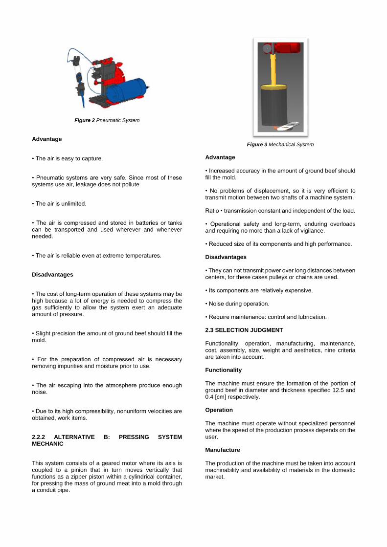
Figure 2 Pneumatic System
Advantage
• The air is easy to capture.
• Pneumatic systems are very safe. Since most of these systems use air, leakage does not pollute
• The air is unlimited.
• The air is compressed and stored in batteries or tanks can be transported and used wherever and whenever needed.
• The air is reliable even at extreme temperatures.
Disadvantages
• The cost of long-term operation of these systems may be high because a lot of energy is needed to compress the gas sufficiently to allow the system exert an adequate amount of pressure.
• Slight precision the amount of ground beef should fill the mold.
• For the preparation of compressed air is necessary removing impurities and moisture prior to use.
• The air escaping into the atmosphere produce enough noise.
• Due to its high compressibility, nonuniform velocities are obtained, work items.
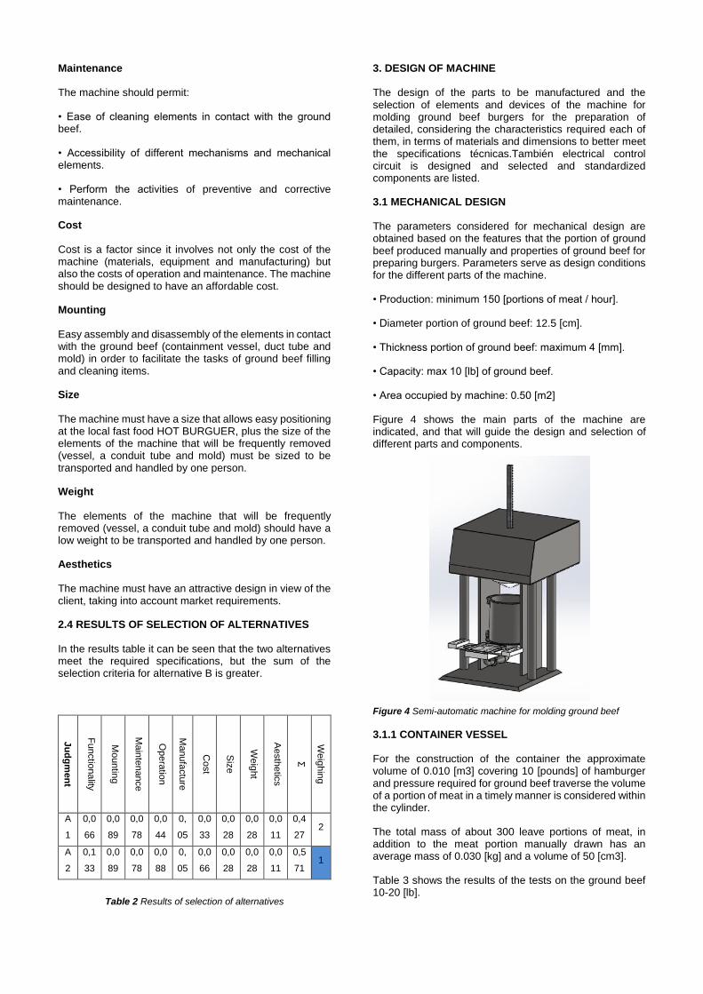
2.2.2 ALTERNATIVE B: PRESSING SYSTEM MECHANIC
This system consists of a geared motor where its axis is coupled to a pinion that in turn moves vertically that functions as a zipper piston within a cylindrical container, for pressing the mass of ground meat into a mold through a conduit pipe.
Figure 3 Mechanical System
Advantage
• Increased accuracy in the amount of ground beef should fill the mold.
• No problems of displacement, so it is very efficient to transmit motion between two shafts of a machine system.
Ratio • transmission constant and independent of the load.
• Operational safety and long-term, enduring overloads and requiring no more than a lack of vigilance.
• Reduced size of its components and high performance.
Disadvantages
• They can not transmit power over long distances between centers, for these cases pulleys or chains are used.
• Its components are relatively expensive.
• Noise during operation.
• Require maintenance: control and lubrication.
2.3 SELECTION JUDGMENT
Functionality, operation, manufacturing, maintenance, cost, assembly, size, weight and aesthetics, nine criteria are taken into account.
Functionality
The machine must ensure the formation of the portion of ground beef in diameter and thickness specified 12.5 and 0.4 [cm] respectively.
Operation
The machine must operate without specialized personnel where the speed of the production process depends on the user.
Manufacture
The production of the machine must be taken into account machinability and availability of materials in the domestic market.
Maintenance
The machine should permit:
• Ease of cleaning elements in contact with the ground beef.
• Accessibility of different mechanisms and mechanical elements.
• Perform the activities of preventive and corrective maintenance.
Cost
Cost is a factor since it involves not only the cost of the machine (materials, equipment and manufacturing) but also the costs of operation and maintenance. The machine should be designed to have an affordable cost.
Mounting
Easy assembly and disassembly of the elements in contact with the ground beef (containment vessel, duct tube and mold) in order to facilitate the tasks of ground beef filling and cleaning items.
Size
The machine must have a size that allows easy positioning at the local fast food HOT BURGUER, plus the size of the elements of the machine that will be frequently removed (vessel, a conduit tube and mold) must be sized to be transported and handled by one person.
Weight
The elements of the machine that will be frequently removed (vessel, a conduit tube and mold) should have a low weight to be transported and handled by one person.
Aesthetics
The machine must have an attractive design in view of the client, taking into account market requirements.
2.4 RESULTS OF SELECTION OF ALTERNATIVES
In the results table it can be seen that the two alternatives meet the required specifications, but the sum of the selection criteria for alternative B is greater.
Ju
dg
men
t
Functio
nality
Mountin
g
Main
tenance
Opera
tion
Manufa
ctu
re
Cost
Siz
e
Weig
ht
Aesth
etic
s
Σ
Weig
hin
g
A
1
0,0
66
0,0
89
0,0
78
0,0
44
0,
05
0,0
33
0,0
28
0,0
28
0,0
11
0,4
27 2
A
2
0,1
33
0,0
89
0,0
78
0,0
88
0,
05
0,0
66
0,0
28
0,0
28
0,0
11
0,5
71 1
Table 2 Results of selection of alternatives
3. DESIGN OF MACHINE
The design of the parts to be manufactured and the selection of elements and devices of the machine for molding ground beef burgers for the preparation of detailed, considering the characteristics required each of them, in terms of materials and dimensions to better meet the specifications técnicas.También electrical control circuit is designed and selected and standardized components are listed.
3.1 MECHANICAL DESIGN
The parameters considered for mechanical design are obtained based on the features that the portion of ground beef produced manually and properties of ground beef for preparing burgers. Parameters serve as design conditions for the different parts of the machine.
• Production: minimum 150 [portions of meat / hour].
• Diameter portion of ground beef: 12.5 [cm].
• Thickness portion of ground beef: maximum 4 [mm].
• Capacity: max 10 [lb] of ground beef.
• Area occupied by machine: 0.50 [m2]
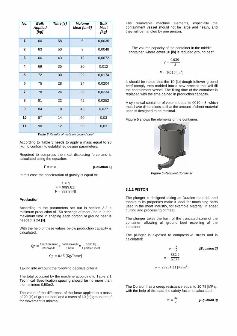
Figure 4 shows the main parts of the machine are indicated, and that will guide the design and selection of different parts and components.
Figure 4 Semi-automatic machine for molding ground beef
3.1.1 CONTAINER VESSEL
For the construction of the container the approximate volume of 0.010 [m3] covering 10 [pounds] of hamburger and pressure required for ground beef traverse the volume of a portion of meat in a timely manner is considered within the cylinder.
The total mass of about 300 leave portions of meat, in addition to the meat portion manually drawn has an average mass of 0.030 [kg] and a volume of 50 [cm3].
Table 3 shows the results of the tests on the ground beef 10-20 [lb].
No. Bulk Applied
[kg]
Time [s] Volume Meat [cm3]
Bulk Meat [kg]
1 60 58 6 0,0036
2 63 50 8 0,0048
3 66 43 12 0,0072
4 69 35 20 0,012
5 72 30 29 0,0174
6 75 28 34 0,0204
7 78 24 39 0,0234
8 81 22 42 0,0252
9 84 18 45 0,027
10 87 14 50 0,03
11 90 12 50 0,03
Table 3 Results of tests on ground beef
According to Table 3 needs to apply a mass equal to 90 [kg] to conform to established design parameters.
Required to compress the meat displacing force and is calculated using the equation:
F = m.a [Equation 1]
In this case the acceleration of gravity is equal to:
a = g F = 90(9.81) F = 882.9 [N]
Production
According to the parameters set out in section 3.2 a minimum production of 150 servings of meat / hour, ie the maximum time in shaping each portion of ground beef is needed is 24 [s].
With the help of these values below production capacity is calculated:
Qp =1portion meat
24seconds x
3600 seconds
1 hourx
0.003 Kg
1 portion meat
Qp = 0.45 [Kg/ hour]
Taking into account the following decisive criteria:
The total occupied by the machine according to Table 2.1 Technical Specification spacing should be no more than the minimum 0,50m2.
The value of the difference of the force applied to a mass of 20 [lb] of ground beef and a mass of 10 [lb] ground beef for movement is minimal.
The removable machine elements, especially the containment vessel should not be large and heavy, and they will be handled by one person.
The volume capacity of the container in the middle container, where cover 10 [lb] is reduced ground beef:
V =0.020
2
V = 0.010 [m3]
It should be noted that the 10 [lb] dough leftover ground beef comply then molded into a new process that will fill the containment vessel. The filling time of the container is replaced with the time gained in production capacity.
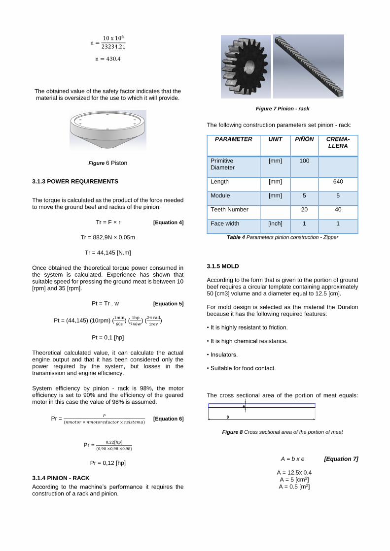
A cylindrical container of volume equal to 0010 m3, which must have dimensions so that the amount of sheet material used is designed to be minimal.
Figure 5 shows the elements of the container.
Figure 5 Recipient Container
3.1.2 PISTON
The plunger is designed taking as Duralon material, and thanks to its properties make it ideal for machining parts used in the meat industry, for example Material: in sheet cutting and processing of meat.
The plunger takes the form of the truncated cone of the container, allowing all ground beef expelling of the container.
The plunger is exposed to compressive stress and is calculated:
𝝈 =𝑭
𝑨 [Equation 2]
σ =882.9
0.038
σ = 23234.21 [N m2⁄ ]
The Duralon has a creep resistance equal to 10.78 [MPa], with the help of this data the safety factor is calculated:
𝒏 =𝑺𝒚
𝝈 [Equation 3]
n =10 x 106
23234.21
n = 430.4
The obtained value of the safety factor indicates that the material is oversized for the use to which it will provide.
Figure 6 Piston
3.1.3 POWER REQUIREMENTS
The torque is calculated as the product of the force needed to move the ground beef and radius of the pinion:
Tr = F × r [Equation 4]
Tr = 882,9N × 0,05m
Tr = 44,145 [N.m]
Once obtained the theoretical torque power consumed in the system is calculated. Experience has shown that suitable speed for pressing the ground meat is between 10 [rpm] and 35 [rpm].
Pt = Tr . w [Equation 5]
Pt = (44,145) (10rpm) (1min
60s) (
1hp
746w) (
2π rad
1rev)
Pt = 0,1 [hp]
Theoretical calculated value, it can calculate the actual engine output and that it has been considered only the power required by the system, but losses in the transmission and engine efficiency.
System efficiency by pinion - rack is 98%, the motor efficiency is set to 90% and the efficiency of the geared motor in this case the value of 98% is assumed.
Pr = 𝑃
(𝑛𝑚𝑜𝑡𝑜𝑟 × 𝑛𝑚𝑜𝑡𝑜𝑟𝑒𝑑𝑢𝑐𝑡𝑜𝑟 × 𝑛𝑠𝑖𝑠𝑡𝑒𝑚𝑎) [Equation 6]
Pr = 0,22[ℎ𝑝]
(0,90 ×0,98 ×0,98)
Pr = 0,12 [hp]
3.1.4 PINION - RACK
According to the machine’s performance it requires the construction of a rack and pinion.
Figure 7 Pinion - rack
The following construction parameters set pinion - rack:
PARAMETER UNIT PIÑÓN CREMA-LLERA
Primitive Diameter
[mm] 100
Length [mm] 640
Module [mm] 5 5
Teeth Number 20 40
Face width [inch] 1 1
Table 4 Parameters pinion construction - Zipper
3.1.5 MOLD
According to the form that is given to the portion of ground beef requires a circular template containing approximately 50 [cm3] volume and a diameter equal to 12.5 [cm].
For mold design is selected as the material the Duralon because it has the following required features:
• It is highly resistant to friction.
• It is high chemical resistance.
• Insulators.
• Suitable for food contact.
The cross sectional area of the portion of meat equals:
Figure 8 Cross sectional area of the portion of meat
A = b x e [Equation 7]
A = 12.5x 0.4
A = 5 [cm2]
A = 0.5 [m2]
All parts in contact with the meat must be removable for easy cleaning, so that the mold is divided into 3 main parts: base, container and lid.
Base
The base is designed to hold other parts of the mold and allow the conduit connecting pipe so that the mold reaches the ground meat container to be molded. It is used as material Duralon.
Container
The container must have two mold holes with the dimensions of the ground meat in the set design parameters, to enable molding a portion of ground meat, while the other portion is removed. It is used as material stainless steel 304 and Duralon.
Top
The lid is designed in order to close the top of the container to compress the ground meat and used as transparent plastic material, and will be transparent to allow viewing filling the ground meat in the mold container.
Figure 9 Mold
3.1.6 STRUCTURE
The structure that supports all the elements of the machine, have the following characteristics:
Force to press the ground beef = 882,9 [N]
Total weight of the cabinet and its elements. = m.g (20kg) (9,81m/s2) = 196,2 [N]
Total Force= 196,2 + 882,9 = 1079,1 [N]
Structure Analysis
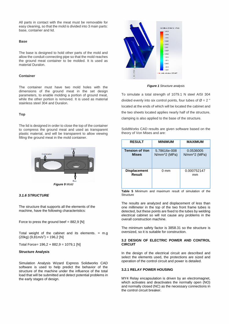
Simulation Analysis Wizard Express Solidworks CAD software is used to help predict the behavior of the structure of the machine under the influence of the total load that will be submitted and detect potential problems in the early stages of design.
Figure 1 Structure analysis
To simulate a total strength of 1079.1 N steel AISI 304
divided evenly into six control points, four tubes of Ø = 2 ''
located at the ends of which will be located the cabinet and
the two sheets located applies nearly half of the structure,
clamping is also applied to the base of the structure.
SolidWorks CAD results are given software based on the theory of Von Mises and are:
RESULT MINIMUM MAXIMUM
Tension of Von Mises
5.78616e-008 N/mm^2 (MPa)
0.0536005 N/mm^2 (MPa)
Displacement Result
0 mm 0.000752147 mm
Table 5 Minimum and maximum result of simulation of the Structure
The results are analyzed and displacement of less than one millimeter in the top of the two front frame tubes is detected, but these points are fixed to the tubes by welding electrical cabinet so will not cause any problems in the overall construction machine.
The minimum safety factor is 3858.31 so the structure is oversized, so it is suitable for construction.
3.2 DESIGN OF ELECTRIC POWER AND CONTROL CIRCUIT
In the design of the electrical circuit are described and select the elements used, the protections are sized and operation of the control circuit and power is detailed.
3.2.1 RELAY POWER HOUSING
MY4 Relay encapsulation is driven by an electromagnet, which activates and deactivates the normally open (NO) and normally closed (NC) as the necessary connections in the control circuit breaker.
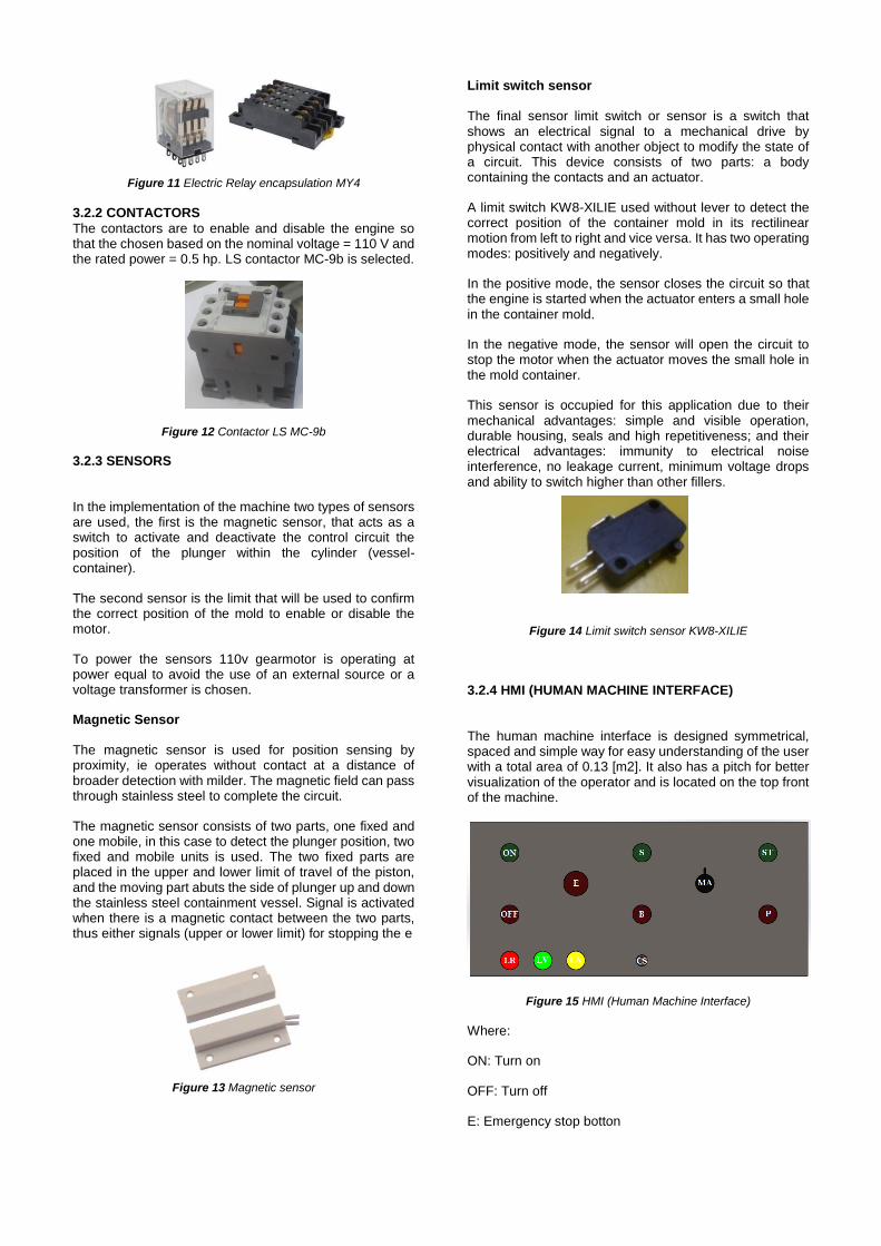
Figure 11 Electric Relay encapsulation MY4 3.2.2 CONTACTORS The contactors are to enable and disable the engine so that the chosen based on the nominal voltage = 110 V and the rated power = 0.5 hp. LS contactor MC-9b is selected.
Figure 12 Contactor LS MC-9b
3.2.3 SENSORS
In the implementation of the machine two types of sensors are used, the first is the magnetic sensor, that acts as a switch to activate and deactivate the control circuit the position of the plunger within the cylinder (vessel-container).
The second sensor is the limit that will be used to confirm the correct position of the mold to enable or disable the motor.
To power the sensors 110v gearmotor is operating at power equal to avoid the use of an external source or a voltage transformer is chosen.
Magnetic Sensor
The magnetic sensor is used for position sensing by proximity, ie operates without contact at a distance of broader detection with milder. The magnetic field can pass through stainless steel to complete the circuit.
The magnetic sensor consists of two parts, one fixed and one mobile, in this case to detect the plunger position, two fixed and mobile units is used. The two fixed parts are placed in the upper and lower limit of travel of the piston, and the moving part abuts the side of plunger up and down the stainless steel containment vessel. Signal is activated when there is a magnetic contact between the two parts, thus either signals (upper or lower limit) for stopping the e
Figure 13 Magnetic sensor
Limit switch sensor
The final sensor limit switch or sensor is a switch that shows an electrical signal to a mechanical drive by physical contact with another object to modify the state of a circuit. This device consists of two parts: a body containing the contacts and an actuator.
A limit switch KW8-XILIE used without lever to detect the correct position of the container mold in its rectilinear motion from left to right and vice versa. It has two operating modes: positively and negatively.
In the positive mode, the sensor closes the circuit so that the engine is started when the actuator enters a small hole in the container mold.
In the negative mode, the sensor will open the circuit to stop the motor when the actuator moves the small hole in the mold container.
This sensor is occupied for this application due to their mechanical advantages: simple and visible operation, durable housing, seals and high repetitiveness; and their electrical advantages: immunity to electrical noise interference, no leakage current, minimum voltage drops and ability to switch higher than other fillers.
Figure 14 Limit switch sensor KW8-XILIE
3.2.4 HMI (HUMAN MACHINE INTERFACE)
The human machine interface is designed symmetrical, spaced and simple way for easy understanding of the user with a total area of 0.13 [m2]. It also has a pitch for better visualization of the operator and is located on the top front of the machine.
Figure 15 HMI (Human Machine Interface)
Where:
ON: Turn on
OFF: Turn off
E: Emergency stop botton
MA: Select Automatic or Manual
S: Upload button in Manual Mode
B: Down button in Manual Mode
ST: Start button in Auto Mode
P: Pause button in Auto Mode
LR: Red Light
LV: Green Light
LA: Yellow Light
CS: Cable Connector Mold
The red light comes on when the machine is turned on, the green light will illuminate when the engine and yellow light indicates to me that is activated automatically.
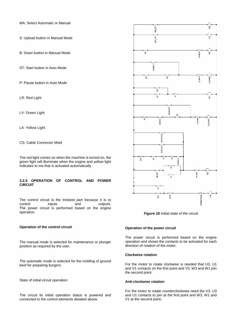
3.2.5 OPERATION OF CONTROL AND POWER CIRCUIT
The control circuit is the trickiest part because it is to control inputs and outputs. The power circuit is performed based on the engine operation.
Operation of the control circuit
The manual mode is selected for maintenance or plunger position as required by the user.
The automatic mode is selected for the molding of ground beef for preparing burgers.
State of initial circuit operation:
The circuit its initial operation status is powered and connected to the control elements detailed above.
Figure 16 Initial state of the circuit
Operation of the power circuit
The power circuit is performed based on the engine operation and shows the contacts to be activated for each direction of rotation of the motor.
Clockwise rotation
For the motor to rotate clockwise is needed that U3, U1 and V1 contacts on the first point and V3, W3 and W1 join the second point.
Anti-clockwise rotation
For the motor to rotate counterclockwise need the V3, U3 and U1 contacts to join at the first point and W3, W1 and V1 at the second point.
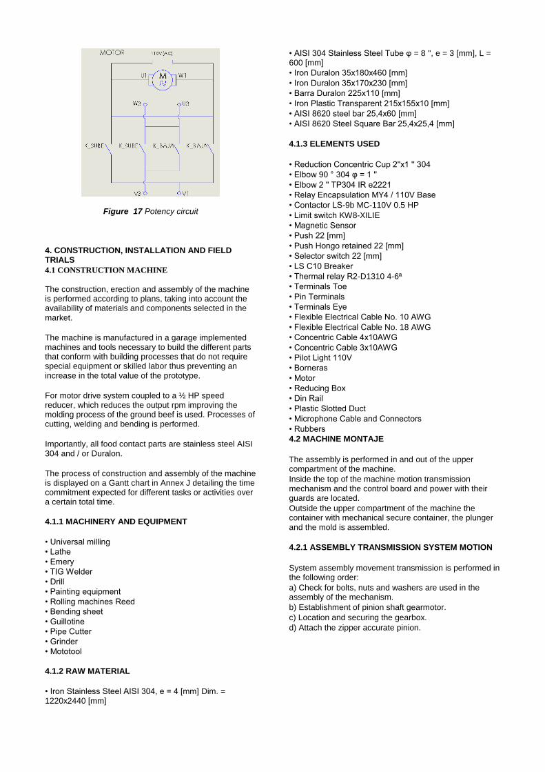
Figure 17 Potency circuit
4. CONSTRUCTION, INSTALLATION AND FIELD TRIALS
4.1 CONSTRUCTION MACHINE
The construction, erection and assembly of the machine is performed according to plans, taking into account the availability of materials and components selected in the market.
The machine is manufactured in a garage implemented machines and tools necessary to build the different parts that conform with building processes that do not require special equipment or skilled labor thus preventing an increase in the total value of the prototype.
For motor drive system coupled to a ½ HP speed reducer, which reduces the output rpm improving the molding process of the ground beef is used. Processes of cutting, welding and bending is performed.
Importantly, all food contact parts are stainless steel AISI 304 and / or Duralon.
The process of construction and assembly of the machine is displayed on a Gantt chart in Annex J detailing the time commitment expected for different tasks or activities over a certain total time.
4.1.1 MACHINERY AND EQUIPMENT
• Universal milling
• Lathe
• Emery
• TIG Welder
• Drill
• Painting equipment
• Rolling machines Reed
• Bending sheet
• Guillotine
• Pipe Cutter
• Grinder
• Mototool
4.1.2 RAW MATERIAL
• Iron Stainless Steel AISI 304, e = 4 [mm] Dim. = 1220x2440 [mm]
• AISI 304 Stainless Steel Tube φ = 8 '', e = 3 [mm], L = 600 [mm]
• Iron Duralon 35x180x460 [mm]
• Iron Duralon 35x170x230 [mm]
• Barra Duralon 225x110 [mm]
• Iron Plastic Transparent 215x155x10 [mm]
• AISI 8620 steel bar 25,4x60 [mm]
• AISI 8620 Steel Square Bar 25,4x25,4 [mm]
4.1.3 ELEMENTS USED
• Reduction Concentric Cup 2''x1 '' 304
• Elbow 90 ° 304 φ = 1 ''
• Elbow 2 '' TP304 IR e2221
• Relay Encapsulation MY4 / 110V Base
• Contactor LS-9b MC-110V 0.5 HP
• Limit switch KW8-XILIE
• Magnetic Sensor
• Push 22 [mm]
• Push Hongo retained 22 [mm]
• Selector switch 22 [mm]
• LS C10 Breaker
• Thermal relay R2-D1310 4-6ª
• Terminals Toe
• Pin Terminals
• Terminals Eye
• Flexible Electrical Cable No. 10 AWG
• Flexible Electrical Cable No. 18 AWG
• Concentric Cable 4x10AWG
• Concentric Cable 3x10AWG
• Pilot Light 110V
• Borneras
• Motor
• Reducing Box
• Din Rail
• Plastic Slotted Duct
• Microphone Cable and Connectors
• Rubbers
4.2 MACHINE MONTAJE
The assembly is performed in and out of the upper compartment of the machine.
Inside the top of the machine motion transmission mechanism and the control board and power with their guards are located.
Outside the upper compartment of the machine the container with mechanical secure container, the plunger and the mold is assembled.
4.2.1 ASSEMBLY TRANSMISSION SYSTEM MOTION
System assembly movement transmission is performed in the following order:
a) Check for bolts, nuts and washers are used in the assembly of the mechanism.
b) Establishment of pinion shaft gearmotor.
c) Location and securing the gearbox.
d) Attach the zipper accurate pinion.
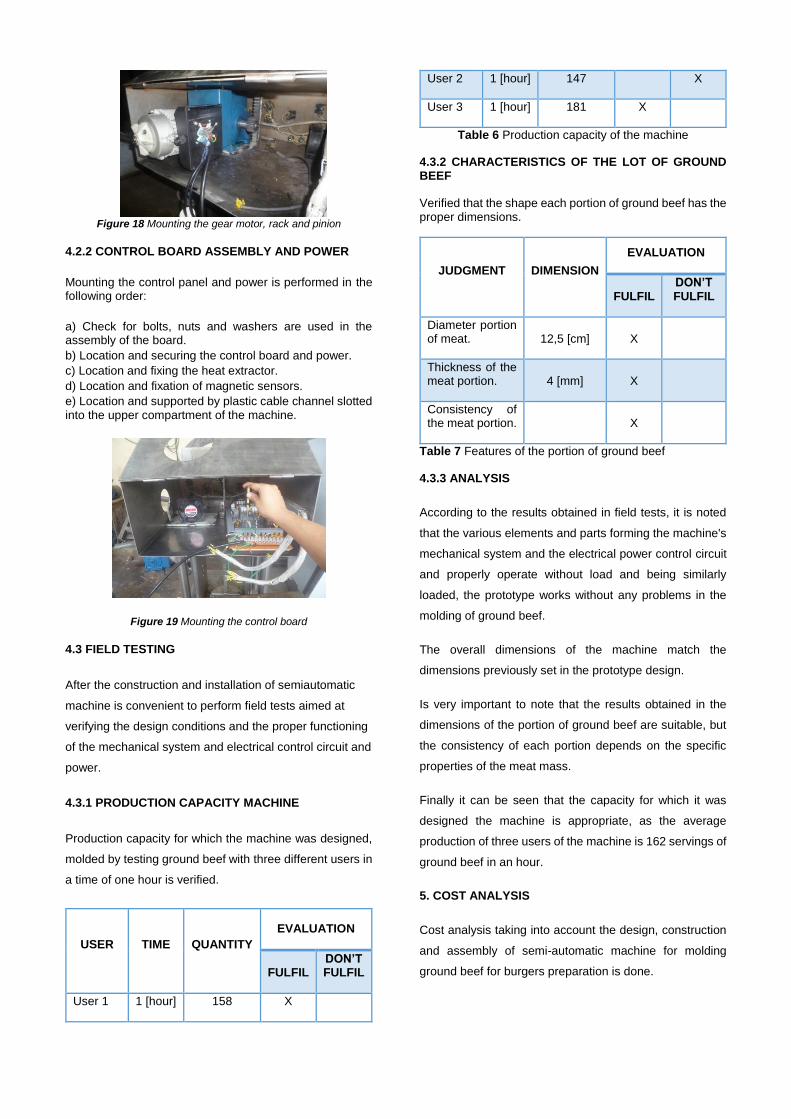
Figure 18 Mounting the gear motor, rack and pinion
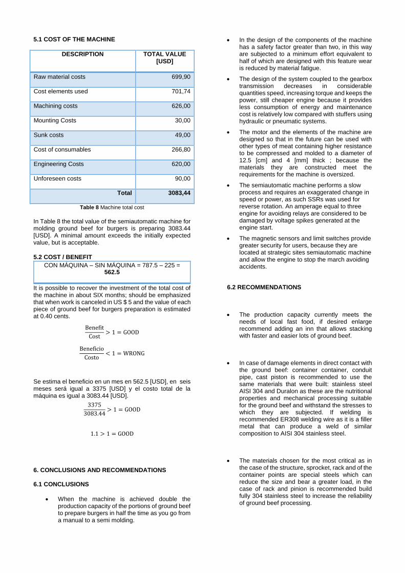
4.2.2 CONTROL BOARD ASSEMBLY AND POWER
Mounting the control panel and power is performed in the following order:
a) Check for bolts, nuts and washers are used in the assembly of the board.
b) Location and securing the control board and power.
c) Location and fixing the heat extractor.
d) Location and fixation of magnetic sensors.
e) Location and supported by plastic cable channel slotted into the upper compartment of the machine.
Figure 19 Mounting the control board
4.3 FIELD TESTING
After the construction and installation of semiautomatic
machine is convenient to perform field tests aimed at
verifying the design conditions and the proper functioning
of the mechanical system and electrical control circuit and
power.
4.3.1 PRODUCTION CAPACITY MACHINE
Production capacity for which the machine was designed,
molded by testing ground beef with three different users in
a time of one hour is verified.
USER TIME QUANTITY
EVALUATION
FULFIL DON’T FULFIL
User 1 1 [hour] 158 X
User 2 1 [hour] 147 X
User 3 1 [hour] 181 X
Table 6 Production capacity of the machine
4.3.2 CHARACTERISTICS OF THE LOT OF GROUND BEEF
Verified that the shape each portion of ground beef has the proper dimensions.
JUDGMENT DIMENSION
EVALUATION
FULFIL DON’T FULFIL
Diameter portion of meat. 12,5 [cm] X
Thickness of the meat portion. 4 [mm] X
Consistency of the meat portion.
X
Table 7 Features of the portion of ground beef
4.3.3 ANALYSIS
According to the results obtained in field tests, it is noted
that the various elements and parts forming the machine's
mechanical system and the electrical power control circuit
and properly operate without load and being similarly
loaded, the prototype works without any problems in the
molding of ground beef.
The overall dimensions of the machine match the
dimensions previously set in the prototype design.
Is very important to note that the results obtained in the
dimensions of the portion of ground beef are suitable, but
the consistency of each portion depends on the specific
properties of the meat mass.
Finally it can be seen that the capacity for which it was
designed the machine is appropriate, as the average
production of three users of the machine is 162 servings of
ground beef in an hour.
5. COST ANALYSIS
Cost analysis taking into account the design, construction
and assembly of semi-automatic machine for molding
ground beef for burgers preparation is done.
5.1 COST OF THE MACHINE
DESCRIPTION TOTAL VALUE [USD]
Raw material costs 699,90
Cost elements used 701,74
Machining costs 626,00
Mounting Costs 30,00
Sunk costs 49,00
Cost of consumables 266,80
Engineering Costs 620,00
Unforeseen costs 90,00
Total 3083,44
Table 8 Machine total cost
In Table 8 the total value of the semiautomatic machine for molding ground beef for burgers is preparing 3083.44 [USD]. A minimal amount exceeds the initially expected value, but is acceptable.
5.2 COST / BENEFIT
CON MÁQUINA – SIN MÁQUINA = 787.5 – 225 = 562.5
It is possible to recover the investment of the total cost of the machine in about SIX months; should be emphasized that when work is canceled in US $ 5 and the value of each piece of ground beef for burgers preparation is estimated at 0.40 cents.
Benefit
Cost> 1 = GOOD
Beneficio
Costo< 1 = WRONG
Se estima el beneficio en un mes en 562.5 [USD], en seis meses será igual a 3375 [USD] y el costo total de la máquina es igual a 3083.44 [USD].
3375
3083.44> 1 = GOOD
1.1 > 1 = GOOD
6. CONCLUSIONS AND RECOMMENDATIONS
6.1 CONCLUSIONS
When the machine is achieved double the production capacity of the portions of ground beef to prepare burgers in half the time as you go from a manual to a semi molding.
In the design of the components of the machine has a safety factor greater than two, in this way are subjected to a minimum effort equivalent to half of which are designed with this feature wear is reduced by material fatigue.
The design of the system coupled to the gearbox transmission decreases in considerable quantities speed, increasing torque and keeps the power, still cheaper engine because it provides less consumption of energy and maintenance cost is relatively low compared with stuffers using hydraulic or pneumatic systems.
The motor and the elements of the machine are designed so that in the future can be used with other types of meat containing higher resistance to be compressed and molded to a diameter of 12.5 [cm] and 4 [mm] thick ; because the materials they are constructed meet the requirements for the machine is oversized.
The semiautomatic machine performs a slow process and requires an exaggerated change in speed or power, as such SSRs was used for reverse rotation. An amperage equal to three engine for avoiding relays are considered to be damaged by voltage spikes generated at the engine start.
The magnetic sensors and limit switches provide greater security for users, because they are located at strategic sites semiautomatic machine and allow the engine to stop the march avoiding accidents.
6.2 RECOMMENDATIONS
The production capacity currently meets the needs of local fast food, if desired enlarge recommend adding an inn that allows stacking with faster and easier lots of ground beef.
In case of damage elements in direct contact with the ground beef: container container, conduit pipe, cast piston is recommended to use the same materials that were built: stainless steel AISI 304 and Duralon as these are the nutritional properties and mechanical processing suitable for the ground beef and withstand the stresses to which they are subjected. If welding is recommended ER308 welding wire as it is a filler metal that can produce a weld of similar composition to AISI 304 stainless steel.
The materials chosen for the most critical as in the case of the structure, sprocket, rack and of the container points are special steels which can reduce the size and bear a greater load, in the case of rack and pinion is recommended build fully 304 stainless steel to increase the reliability of ground beef processing.
It is recommended to increase new dockable molds to the conduit pipe machine to allow me to vary the dimensions and shapes of different types of meat. The use of existing materials on the market reduces the cost of manufacture and in turn decrease the time for construction of the semi-automatic machine.
It is important to proper sizing of the components of the power circuit, taking into account the current peaks when the engine starts, using contactors for passing current to the motor, we recommend using the elements of electrical protection described in Technical Manual since they are previously selected according to operation of the machine.
The use of robust components and their maintenance in machine design ensures durability for sensors and components of the HMI, so it is recommended to finish the molding process immediately flush the steam to prevent the meat from sticking ground to the walls and difficult access points of the elements
.REFERENCES
Alexander, C. K., & Sadiku, M. N. (2007). Fundamentos de Circuitos Eléctricos. México: Litográfica Ingramex, S.A. de C.V.
Appold, H., Feiler, K., Reinhard, A., & Schmidt, P. (1995). Tecnología de los metales. Barcelona: Reverté, S.A.
Aula Eléctrica. (s/a). Automatismos Industriales. Obtenido
de Relé térmico: http://guindo.pntic.mec.es/rarc0002/all/aut/dat/f.rele.termico.pdf
Boylestad, R. L. (2004). Introducción al análisis de circuitos. Pearson Educación.
Budynas, R. G., & Nisbett, J. K. (2008). Diseño en ingeniería mecánica de Shigley. México: McGRAW-HILL .
Caldinox. (s/a). Aceros Inoxidables. Obtenido de
http://www.caldinox.com.ar/productos_y_servicios/productos/tuberias_y_accesorios_con_uniones_a_clamp_y_uniones_dobles_danesas
Condimensa. (s/a). Apanadura. Recuperado el Enero de 2014, de http://www.condimensa.com.ec/materias2.html
Electricos Generales. (2012). Relay Encapsulado. Obtenido de http://www.electricosgenerales.com.pe/shop/relay-encapsulado/
Galvanizados Lacunza, S.A. (s/a). Galvanizado. Obtenido de http://www.galvanizadoslacunza.com/GalvanizadoyBeneficios.htm
Geoka. (s/a). Cono Truncado. Obtenido de
http://www.geoka.net/poliedros/cono_truncado.html
Gepowercontrols. (s/a). Relés térmicos. Obtenido de
www.gepowercontrols.com/es/.../Electronic_Overload_Relay.html
Grupo Carrion Alvarez. (s/a). HOJA DE DATOS - Características y aplicaciones del duralon.
Hamrock, B. J., Jacobson, B. O., & Schmid, S. R. (2000). Elementos de Máquinas. México: McGRAW-HILL.
Hoffman Enclosures Inc. (2009). NORMAS GLOBALES PARA GABINETES ELÉCTRICOS. Obtenido de http://www.hoffmanonline.com/stream_document.aspx?rRID=245286&pRID=245285
Horwitz, H. (2002). Soldadura: Aplicaciones y Práctica. México: Alfaomega.
Ingeniería Teleinfórmatica. (s/a). Física General II. Obtenido de www.es.scribd.com/doc/38513543
Leon Vega, A. L. (1992). Diseño, cálculo y construcción de una roladora manual - Informe Técnico.
Guayaquil: ESCUELA POLITECNICA DEL LITORAL.
Mercado en línea - China. (2011). Sensores. Obtenido de
http://spanish.dooraccesscontroller.com/
Molina, P. (s/a). Protección de los Circuitos Eléctricos.
Obtenido de http://www.profesormolina.com.ar/electromec/prot_circ_elect.htm
Mott, R. L. (2006). Diseño de Elementos de Máquinas. México: PEARSON EDUCACIÓN.
Obtesol. (s/a). Aceros Inoxidables. Obtenido de http://www.obtesol.es/index.php?option=com_content&task=category§ionid=4&id=34&Itemid=30
Riba, C. (2002). Diseño Concurrente. Barcelona: EDICIONES UPC.
Rivas Arias, J. M. (2009). Soldadura eléctrica y sistemas T.I.G. y M.A.G. Madrid: Paraninfo.
SOLTER. (s/a). Soldadura TIG. Obtenido de http://www.solter.com/es/procesos-soldadura/tig
SOLYSOL. (2012). Soldadura GTAW - TIG. Obtenido de http://www.solysol.com.es/productos-y-servicios/procesos-soldadura/soldadura-gtaw-tig/
SUMELEC. (2014). Automatización Eléctrica Industrial. Obtenido de http://www.sumelec.net/cat%C3%A1logo.html
ABOUT THE AUTHOR
Jefferson V. V. Andrade, born in Ibarra - Ecuador on July 8th/1989. He did his secondary education at the "Sánchez y Cifuentes' College. He culminated his studies at the Technical University of the North in the Engineering Mechatronics in 2014.
Areas of interest: Automation and Process Control, Robotics, Microelectronics, Renewable Energy
Contact: [email protected].