Embed Size (px)
Citation preview

UNIVERSIDADE FEDERAL DO ESPÍRITO SANTO CENTRO TECNOLÓGICO
PROGRAMA DE PÓS-GRADUAÇÃO EM ENGENHARIA ELÉTRICA
PEDRO PAULO FAVATO BARCELOS
ONTOLOGY-BASED PROVISIONING FOR TECHNOLOGY-
INDEPENDENT MULTI-LAYER TRANSPORT NETWORKS
VITÓRIA
2015

PEDRO PAULO FAVATO BARCELOS
ONTOLOGY-BASED PROVISIONING FOR TECHNOLOGY-
INDEPENDENT MULTI-LAYER TRANSPORT NETWORKS
Tese apresentada ao Programa de Pós-Graduação em Engenharia Elétrica do Centro Tecnológico da Universidade Federal do Espírito Santo, como requisito parcial para obtenção do Grau de Doutor em Engenharia Elétrica.
Orientador: Prof. Dr. Anilton Salles Garcia
Coorientador: Prof. Dr. Maxwell E. Monteiro
VITÓRIA
2015

Dados Internacionais de Catalogação-na-publicação (CIP) (Biblioteca Setorial Tecnológica,
Universidade Federal do Espírito Santo, ES, Brasil)
Barcelos, Pedro Paulo Favato, 1985- B242o Ontology-based provisioning for technology-independent
multi-layer transport networks / Pedro Paulo Favato Barcelos. – 2015.
210 f. : il. Orientador: Anilton Salles Garcia. Coorientador: Maxwell Eduardo Monteiro. Tese (Doutorado em Engenharia Elétrica) – Universidade
Federal do Espírito Santo, Centro Tecnológico. 1. Ontologia. 2. Telecomunicações. 3. Redes de
computadores – Gerência. 4. Redes ópticas de transporte. 5. Aprovisionamento de rede. 6. Sistema baseado em conhecimento. 7. Interoperabilidade semântica. I. Garcia, Anilton Salles. II. Monteiro, Maxwell Eduardo. III. Universidade Federal do Espírito Santo. Centro Tecnológico. IV. Título.
CDU: 621.3

PEDRO PAULO FAVATO BARCELOS
ONTOLOGY-BASED PROVISIONING FOR TECHNOLOGY-
INDEPENDENT MULTI-LAYER TRANSPORT NETWORKS
Tese apresentada ao Programa de Pós-Graduação em Engenharia Elétrica do Centro Tecnológico da Universidade Federal do Espírito Santo, como requisito parcial para obtenção do Grau de Doutor em Engenharia Elétrica.
Aprovada em 18 de dezembro de 2015.
COMISSÃO EXAMINADORA
Prof. Dr. Anilton Salles Garcia – Orientador Universidade Federal do Espírito Santo
Prof. Dr. Maxwell E. Monteiro – Coorientador Instituto Federal do Espírito Santo
Prof. Dr. João Paulo Andrade Almeida Universidade Federal do Espírito Santo
Prof. Dr. José Augusto Suruagy Monteiro Universidade Federal de Pernambuco
Prof.ª Dr.ª Maria Luiza Machado Campos Universidade Federal do Rio de Janeiro
Prof. Dr. Pedro Frosi Rosa Universidade Federal de Uberlândia

AGRADECIMENTOS
À minha esposa Schwanny por todo amor, auxílio, atenção e paciência. Tenho
certeza de que, sem ela ao meu lado, nada disso seria possível!
Aos orientadores Prof. Dr. Anilton S. Garcia e Prof. Dr. Maxwell E. Monteiro, pelas
contribuições fundamentais ao desenvolvimento deste trabalho e por todo meu
crescimento acadêmico nesses oito anos de trabalhos juntos.
Aos membros da banca, Prof. Dr. João Paulo Andrade Almeida, Prof. Dr. José
Augusto Suruagy Monteiro, Prof.ª Dr.ª Maria Luiza Machado Campos e Prof. Dr.
Pedro Frosi Rosa, pelo tempo dedicado na avaliação e pelas contribuições
realizadas a esta tese.
Ao Programa de Pós-Graduação em Engenharia Elétrica da Universidade Federal
do Espírito Santo, pela oportunidade.
À PADTEC S.A. e sua equipe, pelos projetos onde pudemos aplicar ontologias de
forma prática a redes de transporte, o que muito auxiliou no desenvolvimento do
meu doutorado.
Aos amigos pesquisadores Freddy Brasileiro, pela ajuda na codificação da
ferramenta aqui apresentada, e Cássio Reginato, por todas as discussões e ajudas
relacionadas ao modelo conceitual da tese. Aos professores do Nemo que me
receberam durante anos em seu laboratório como colaborador. E a todos os muitos
amigos do Nemo que viveram comigo grande parte do meu doutorado, pelas ideias
e discussões que muito me ajudaram a crescer no campo da modelagem conceitual.
Aos amigos do Labtel, em especial ao Rodrigo Stange, companheiro da graduação
ao doutorado. Aos professores e a toda a equipe de suporte do Labtel, em especial
ao prof. Marcelo Segatto, que gentilmente me cedeu um computador para trabalho.
Ao professor Victor Villagrá e à Verónica Mateos que me receberam muito bem na
Universidad Politécnica de Madrid.
A todos meus familiares e amigos pelo apoio e companheirismo, sempre. Por fim, a
todos que acreditaram e torceram por mim!

RESUMO
O aprovisionamento é uma atividade importante na configuração de redes. A
Recomendação ITU-T M.3400 define aprovisionamento de redes como sendo os
"procedimentos necessários para se colocar um equipamento em serviço, não
incluindo a instalação". Os aprovisionamentos de recursos e de serviços são
desafios recentes no planejamento de redes de comunicação, sendo atividades
importantes nos paradigmas de redes futuras, como as redes orientadas a serviços,
as redes em nuvem e a virtualização de redes. Considerando os problemas
identificados na literatura, esta tese investiga o uso de tecnologias semânticas,
especialmente ontologias, para resolver o problema da falta de interoperabilidade na
área e o uso dessas tecnologias como base para uma solução computacional capaz
de aprovisionar redes de transporte multicamadas independentes de tecnologia
considerando os estados dos equipamentos da rede. Esta tese tem como objetivo
desenvolver uma solução computacional para as redes de transporte, contribuindo
assim com a área de aprovisionamento de redes, uma subárea da gerência de
redes. Para atingir esse objetivo, (i) uma Ontologia de Referência para redes de
transporte multicamadas independentes de tecnologia foi construída com base na
Recomendação ITU-T G.800 utilizando-se de uma linguagem de ontologias bem
fundamentada e expressiva para a definição de uma semântica precisa para a área.
Essa Ontologia de Referência permite a comunicação, a aprendizagem e a
interoperação na área de redes de transporte. Além disso, (ii) um modelo de rede
semanticamente melhorado para o aprovisionamento de redes de transporte, aqui
chamado Ontologia Computacional em OWL, foi gerado a partir da Ontologia de
Referência através de uma rígida engenharia de ontologias; e (iii) foi implementado
um sistema baseado em conhecimento para aprovisionamento de redes de
transporte que usa a Ontologia Computacional em OWL como base de
conhecimento. Os resultados de um teste em uma Rede Óptica de Transporte
confirmam que o sistema desenvolvido é capaz de realizar o aprovisionamento de
circuitos e o aprovisionamento de conexões em redes de transportes multicamadas
considerando os estados dos equipamentos.
Palavras-chave: rede de transporte, aprovisionamento de rede, ontologia, sistema
baseado em conhecimento.
ABSTRACT
Provisioning is an important activity in the configuration of networks. The ITU-T
Recommendation M.3400 defines network provisioning as the "procedures which are
necessary to bring an equipment into service, not including installation". Resource
and service provisioning are recent challenges in communication network planning
and important activities in paradigms of future networking, like service-oriented
networks, cloud networking, and network virtualization. Considering the problems
identified in the literature, this thesis investigates the use of semantic technologies,
especially ontologies, to solve the lack of interoperability in the transport network
area and the use of these technologies as the basis for a computational solution that
can provision technology-independent multi-layer transport networks considering the
networks equipment states. This thesis contributes to the network provisioning area,
a subarea of network management, by developing an ontology-based provisioning
solution for technology-independent multi-layer transport networks. To accomplish
this objective, (i) an Ontology Reference Model for technology-independent multi-
layer transport networks based on the Recommendation ITU-T G.800 was built with
an expressive well-founded ontology language to the definition of precise semantics.
The Ontology Reference Model allows communication, learning, and interoperation in
the transport network area. In addition, (ii) a semantically improved network model for
the provisioning of transport networks, here called OWL Computational Ontology,
was generated from the Ontology Reference Model through a rigid ontology
engineering; and (iii) an ontology-based network provisioning knowledge-based
system that uses the OWL Computational Ontology as a knowledge base was
implemented. Results of a test on an Optical Transport Network example confirm that
the developed system is able to perform circuit provisioning and connection
provisioning on multi-layer transport networks considering the equipment states.
Keywords: transport network, network provisioning, ontology, knowledge-based
system.

LIST OF FIGURES
Figure 1-1 – Management hierarchy. Adapted from (ITU-T, 2010) ............................ 19
Figure 1-2 – Provisioning in different network abstractions ....................................... 20
Figure 1-3 – Network provisioning related works ....................................................... 25
Figure 1-4 – Visual schema of the thesis structure .................................................... 30
Figure 2-1 – Content distribution of chapter 2 ........................................................... 33
Figure 2-2 – Sublayering within the optical layer. From (DOVERSPIKE; YATES, 2012) ......................................................................................................................... 38
Figure 2-3 – Overview of the existing information models and their influences. Adapted from (HAM et al., 2014) ............................................................................... 51
Figure 3-1 – Use of models in software development. Adapted from (KELLY; TOLVANEN, 2008) .................................................................................................... 63
Figure 3-2 – The Model Driven Architecture models and transformations ................. 65
Figure 3-3 – Separation of concerns via different types of MDA models ................... 69
Figure 3-4 – Model transformation. From (OBJECT MANAGEMENT GROUP, 2003) .................................................................................................................................. 70
Figure 3-5 – The three-phased ontology engineering presented in (GUIZZARDI, 2007) ......................................................................................................................... 71
Figure 3-6 – Association between MDA models and different ontology models ........ 73
Figure 3-7 – Development method of ontology reference models. From (BARCELOS; GUIZZARDI; GARCIA, 2013) .................................................................................... 74
Figure 3-8 – Different computational ontologies considering different design issues 82
Figure 3-9 – Transformation's conceptual view ......................................................... 83
Figure 3-10 – OOTOS as an MDA transformation. Adapted from (OBJECT MANAGEMENT GROUP, 2003) ............................................................................... 85
Figure 4-1 – Ontological deficiencies. From (BARCELOS et al., 2011), based on (FETTKE; LOOS, 2005; GUIZZARDI, 2005) ............................................................. 88
Figure 4-2 – Technologies defined over the functional architecture of the ITU-T G.805. Adapted from (ITU-T, 2010) ........................................................................... 91
Figure 4-3 – Example of the ITU-T G.800 visual notation. From (ITU-T, 2012a) ....... 94
Figure 4-4 – The three ontologies of the Ontology Reference Model ........................ 96
Figure 4-5 – Example of a diagram from the Rec. ITU-T G.800 OntoUML Ontology 97
Figure 4-6 – Relation between different architectural components ............................ 98
Figure 4-7 – Equipment composition at the Simple Equipment OntoUML Ontology . 99
Figure 4-8 – Equipment interfaces’ bindings and connections .................................. 99
Figure 4-9 – The complete Simple Site OntoUML Ontology .................................... 100
Figure 5-1 – The ontology-based provisioning tool parts ......................................... 101
Figure 5-2 – Decomposition of the provisioning tool ................................................ 102
Figure 5-3 – Provisioning tool decomposition in knowledge base and reasoning engine ..................................................................................................................... 102
Figure 5-4 – Decomposing the knowledge base in TBox and ABox ........................ 103
Figure 5-5 – Different ontology models used and their relation ............................... 104
Figure 5-6 – Taxonomy of transport function ........................................................... 106
Figure 5-7 – Main relations of the design model ...................................................... 107
Figure 5-8 – Different use of the relations int_binds and path ................................. 108
Figure 5-9 – Inputs and outputs in the design model ............................................... 108
Figure 5-10 – Fragment of the allowed bindings between inputs and outputs ......... 109
Figure 5-11 – Layer network relationships .............................................................. 110
Figure 5-12 – OWL ontology models in the knowledge base .................................. 111
Figure 5-13 – Taxonomy representation (left box) and OntoGraf representation (right box) ......................................................................................................................... 113
Figure 5-14 – Consistency Model DL expressivity ................................................... 114
Figure 5-15 – Consistency Model metrics ............................................................... 114
Figure 5-16 – Parameters used in the Inference Model generation ......................... 115
Figure 5-17 – Inference Model DL expressivity ....................................................... 116
Figure 5-18 – Inference Model metrics .................................................................... 117
Figure 5-19 – Network specification ........................................................................ 119
Figure 5-20 – ABox constitution .............................................................................. 120

Figure 5-21 – Knowledge base formation ................................................................ 120
Figure 5-22 – Stages of the provisioning tool logic .................................................. 123
Figure 5-23 – Complete provisioning tool flowchart ................................................. 124
Figure 5-24 – Provisioning tool Input Stage............................................................. 125
Figure 5-25 – Provisioning tool final procedure ....................................................... 127
Figure 5-26 – Reasoning procedure ........................................................................ 128
Figure 5-27 – Provisioning tool Setup Stage ........................................................... 129
Figure 5-28 – Manual provisioning flowchart ........................................................... 130
Figure 5-29 – Use of variables in the manual provisioning ...................................... 131
Figure 5-30 – Example of VAR_OUT candidates’ selection .................................... 132
Figure 5-31 – Matrix protection special case ........................................................... 133
Figure 5-32 – Example of VAR_IN candidates’ selection ........................................ 135
Figure 5-33 – Automatic provisioning flowchart ....................................................... 137
Figure 5-34 – Simple example of the automatic provisioning steps ......................... 138
Figure 5-35 – Example of network to be automatically provisioned ......................... 141
Figure 5-36 – Example of unrestricted automatic path provisioning ........................ 142
Figure 5-37 – Example of restricted automatic path provisioning ............................ 143
Figure 5-38 – Examples of restrictions’ and priority’s influence over automatic path finding ...................................................................................................................... 144
Figure 6-1 – Topology to be provisioned ................................................................. 149
Figure 6-2 – OTN layer hierarchy used in the example ........................................... 151
Figure 6-3 – Physical Media Equipment .................................................................. 152
Figure 6-4 – Amplifier (AMP) internal structure ....................................................... 152
Figure 6-5 – OTN Switch architecture. From (DILEM et al., 2013) .......................... 154
Figure 6-6 – Client Interface Card definition ............................................................ 155
Figure 6-7 – ODU Switch and WSS definitions ....................................................... 156
Figure 6-8 – Network Interface Card definition ........................................................ 157
Figure 6-9 – Optical Interface Card definition .......................................................... 158

Figure 6-10 – Declared equipment available in the example ................................... 159
Figure 6-11 – Possible equipment available in the example ................................... 160
Figure 6-12 – Topological representation of the paths to be provisioned ................ 161
Figure 6-13 – Loading of the knowledge base, declared, and possible equipment . 162
Figure 6-14 – INT_SOURCE, INT_SINK, and provisioning mode selection ............ 163
Figure 6-15 – Restrictions and priority definitions .................................................... 163
Figure 6-16 – Path selection options ....................................................................... 164
Figure 6-17 – Combined topological and transport view of the provisioned working path ......................................................................................................................... 165
Figure 6-18 – Validation checking and new provisioning option .............................. 166
Figure 6-19 – Manual provisioning .......................................................................... 166
Figure 6-20 – First part of the manual provisioning (provisioning of EQ1 modules) 167
Figure 6-21 – Invalid network provisioning .............................................................. 169
Figure 6-22 – Second part of the manual provisioning ............................................ 171
Figure 6-23 – End of provisioning process .............................................................. 172
Figure 6-24 – Topological representation of the provisioned paths ......................... 172
Figure 6-25 – Representation of the provisioned paths at the complete network .... 173
Figure 6-26 – Test network with N layers ................................................................ 176
Figure 6-27 – Proportion of each evaluated time when varying the number of layers ................................................................................................................................ 177
Figure 6-28 – Exponential characteristic of the path finding when no restrictions are defined .................................................................................................................... 178
Figure 6-29 – Restriction tests representing the restrictions’ use importance ......... 179
Figure 7-1 – Contributions of the published works to the thesis .............................. 188
Figure II-1 – Network declaration parts ................................................................... 206
Figure II-2 – Amplifier used in the network declaration example ............................. 207
Figure II-3 – Instance population definition .............................................................. 207
Figure II-4 – Object property population definition ................................................... 208

Figure II-5 – Data property population definition ...................................................... 209

LIST OF TABLES
Table 2-1 – Overview of the existing network models. Adapted from (HAM et al., 2014) ......................................................................................................................... 49
Table 5-1 – Allowed bindings according to the design model .................................. 109
Table 5-2 – Reasoning comparison for consistency and Inference Models ............ 118
Table 6-1 – Possible elements and their colors ....................................................... 150
Table 6-2 – Paths' attributes and interfaces ............................................................ 174
Table 6-3 – Path finding time for no limits set.......................................................... 177
Table I-1 – Design Model and Inference Model SWRL Rules ................................. 203
Table II-1 – Amplifier’s instance population ............................................................. 207
Table II-2 – Amplifier’s object property population ................................................... 208
Table II-3 – Data properties' declaration .................................................................. 209

ABBREVIATIONS AND ACRONYMS
ABox – Assertional Box AF – Adaptation Function AMP – Amplifier API – Application Programming Interface ATM – Asynchronous Transfer Mode BGP – Border Gateway Protocol BWW – Bunge-Wand-Weber Ontology CAPEX – Capital Expenditure CIC – Client Interface Card CIM – Common Information Model (in chapter 2) CIM – Computation Independent Model (in chapter 3) DC – Data Center DL – Description Logic DOLCE – Descriptive Ontology for Linguistic and Cognitive Engineering DWDM – Dense Wavelength Division Multiplexing EBNF – Extended Backus-Naur Form EMS – Element Management System EON – Elastic Optical Networking GCI – Global City Indicators GENI – Global Environment for Network Innovations GEYSERS – Generalized Architecture for Dynamic Infrastructure Services GLGPL – GNU Lesser General Public License GMPLS – Generalized Multi-Protocol Label Switching HTML – HyperText Markup Language IaaS – Infrastructure-as-a-Service IEEE – Institute of Electrical and Electronics Engineers IETF – Internet Engineering Task Force IMF – Information Modeling Framework INDL – Infrastructure and Network Description Language IP – Internet Protocol IT – Information Technology ITU – International Telecommunication Union ITU-T – ITU Telecommunication Standardization Sector KBS – Knowledge-based System MDA – Model-Driven Architecture MDD – Model-Driven Development MPLS – Multi-Protocol Label Switching MPLS-TP – Multi-Protocol Label Switching Transport Profile NaaS – Network-as-a-Service NDL – Network Description Language NE – Network Element NGSON – Next Generation Service Overlay Network NIC – Network Interface Card NML – Network Markup Language NOVI – Networking over Virtualized Infrastructures NRDL – Network Resource Description Language OAM – Operation, Administration and Maintenance OAM&P – Operations, Administration, Maintenance, and Provisioning OCh – Optical Channel OCL – Object Constraint Language ODU – Optical Data Unit OFDM – Orthogonal Frequency Division Multiplexing OIC – Optical Interface Card OIF – Optical Internetworking Forum OLED – OntoUML Lightweight Editor OMA – Open Mobile Alliance OMG – Object Management Group OMS – Optical Multiplex Section OOTN – Ontology for Optical Transport Networks OOTOS – OntoUML and OCL to OWL and SWRL Transformation OPEX – Operational Expenditure ORCA-BEN – Open Resource Control Architecture-Breakable Experimental Network OSE – Open Service Environment

OSPF-TE – Open Shortest Path First-Traffic Engineering OTN – Optical Transport Network OTS – Optical Transmission Section OWA – Open World Assumption OWL – Web Ontology Language PIM – Platform Independent Model PM – Physical Media PSM – Platform-Specific Model QoS – Quality of Service RDF – Resource Description Framework RDF-S – Resource Description Framework Schema RSA – Route and Spectrum Assignment RWA – Routing and Wavelength Assignment SDF – Service Delivery Framework SDH – Synchronous Digital Hierarchy SDN – Software Defined Networking SDON – Software-Defined Optical Network SIMF – Semantic Information Model Federation SLICE – Spectrum-sliced Elastic Optical Path Network SNE – System and Network Engineering SO – Specific Objective SOA – Service-Oriented Architecture SONET – Synchronous Optical Networking SS7 – Signaling System No. 7 SWRL – Semantic Web Rule Language TBox – Terminological Box TF – Termination Function TMN – Telecommunications Management Network TPF – Transport Processing Function UCP – Unified Control Plane UFO – Unified Foundational Ontology UML – Unified Modeling Language UNA – Unique Name Assumption UTP – Unshielded Twisted Pair VON – Virtual Optical Network VxDL – Virtual Resources and Interconnection Networks Description Language W3C – World Wide Web Consortium WDM – Wavelength Division Multiplexing WSON – Wavelength Switched Optical Network WSS – Wavelength Selective Switch XML – eXtensible Markup Language

SUMMARY
1 INTRODUCTION ................................................................................................ 18
1.1 MOTIVATION ................................................................................................... 20
1.1.1 SERVICE PROVISIONING DEPENDENCE ON THE INFRASTRUCTURE LAYER ............. 20
1.1.2 ABSENCE OF FORMAL SEMANTICS AND LACK OF INTEROPERABILITY .................... 21
1.1.3 NEED FOR AUTOMATION .................................................................................. 22
1.1.4 LIMITED CONSIDERATION OF NETWORK EQUIPMENT .......................................... 22
1.1.5 TECHNOLOGY DEPENDENCE ............................................................................ 23
1.1.6 LIMITED LAYERING CONSIDERATIONS ................................................................ 23
1.2 PROPOSAL AND JUSTIFICATION ........................................................................ 26
1.3 OBJECTIVES ................................................................................................... 29
1.4 THESIS STRUCTURE ........................................................................................ 30
2 NETWORK PROVISIONING: RECENT AND RELATED WORKS ................................ 33
2.1 SERVICE LAYER PROVISIONING ........................................................................ 34
2.2 INFRASTRUCTURE LAYER PROVISIONING ........................................................... 37
2.2.1 CONTROL PLANE DISCUSSIONS ........................................................................ 38
2.2.2 RECENT STUDIES ON LIGHTPATH PROVISIONING ................................................ 41
2.3 ONTOLOGY-BASED PROVISIONING .................................................................... 44
2.4 EXISTING TRANSPORT NETWORK MODELS ........................................................ 47
2.5 PATH FINDING IN TECHNOLOGY-INDEPENDENT MULTI-LAYER NETWORKS ............ 52
2.5.1 AN ITU-T G.805 NETWORK MODEL AND ALGEBRA FOR CONNECTIONS ............... 53
2.5.2 A PATH FINDING SOLUTION FOR TECHNOLOGY-INDEPENDENT MULTI-LAYER
NETWORKS ................................................................................................................. 57
3 ONTOLOGIES AND ONTOLOGY-BASED DEVELOPMENT METHOD .......................... 61
3.1 MODEL-DRIVEN DEVELOPMENT ........................................................................ 63
3.2 MODEL-DRIVEN ARCHITECTURE ....................................................................... 64
3.2.1 MDA VIEWPOINTS AND MODELS: THE SEPARATION OF CONCERNS ..................... 66
3.2.1.1 THE COMPUTATION INDEPENDENT MODEL (CIM) ............................................... 66
3.2.1.2 THE PLATFORM INDEPENDENT MODEL (PIM) .................................................... 67
3.2.1.3 THE PLATFORM SPECIFIC MODEL (PSM) .......................................................... 68
3.2.2 MDA MODEL TRANSFORMATIONS .................................................................... 69
3.3 ONTOLOGY-BASED DEVELOPMENT OF APPLICATIONS ......................................... 70

3.3.1 ONTOLOGY REFERENCE MODELS ..................................................................... 74
3.3.2 COMPUTATIONAL ONTOLOGIES ......................................................................... 77
3.3.2.1 OWL: THE WEB ONTOLOGY LANGUAGE ........................................................... 78
3.3.2.2 REASONING MECHANISMS ............................................................................... 80
3.3.3 DESIGN STAGE ............................................................................................... 81
3.3.3.1 OOTOS: TRANSFORMATION FROM ONTOUML AND OCL TO OWL AND SWRL ... 83
4 WELL-FOUNDED ONTOLOGY REFERENCE MODEL FOR TECHNOLOGY-INDEPENDENT
MULTI-LAYER TRANSPORT NETWORKS.......................................................................... 86
4.1 TRULY ONTOLOGICAL DISTINCTIONS FOR STANDARDIZATIONS ............................ 86
4.2 THE RECOMMENDATION ITU-T G.800 .............................................................. 90
4.2.1 RECOMMENDATION’S MAIN CONCEPTS ............................................................. 92
4.2.2 RECOMMENDATION’S CRITICISMS ..................................................................... 94
4.3 THE RECOMMENDATION ITU-T G.800 ONTOLOGY REFERENCE MODEL ............... 95
4.3.1 THE ITU-T G.800 ONTOLOGY .......................................................................... 97
4.3.2 THE SIMPLE EQUIPMENT ONTOLOGY ................................................................ 98
4.3.3 THE SIMPLE SITE ONTOLOGY ......................................................................... 100
5 AN ONTOLOGY-BASED TECHNOLOGY-INDEPENDENT MULTI-LAYER TRANSPORT
NETWORKS PROVISIONING TOOL ................................................................................ 101
5.1 THE KNOWLEDGE BASE ................................................................................. 103
5.1.1 THE TERMINOLOGICAL BOX ............................................................................ 104
5.1.1.1 THE ITU-T G.800 ONTOUML DESIGN MODEL FOR PROVISIONING OF TRANSPORT
NETWORKS ............................................................................................................... 105
5.1.1.2 THE ITU-T G.800 OWL ONTOLOGY FOR TRANSPORT NETWORK PROVISIONING 111
5.1.2 THE ASSERTIONAL BOX ................................................................................. 118
5.2 HERMIT: THE PROVISIONING TOOL REASONING ENGINE ................................... 121
5.3 THE PROVISIONING TOOL LOGIC .................................................................... 122
5.3.1 INPUT STAGE ................................................................................................ 125
5.3.2 SETUP STAGE ............................................................................................... 129
5.3.3 PROVISIONING STAGE ................................................................................... 130
5.3.3.1 MANUAL PROVISIONING ................................................................................. 130
5.3.3.2 AUTOMATIC PROVISIONING ............................................................................ 137
6 ONTOLOGY-BASED PROVISIONING IN AN OPTICAL TRANSPORT NETWORK ......... 148
6.1 EXAMPLE SETTINGS ...................................................................................... 149

6.1.1 EQUIPMENT INTERNAL STRUCTURE DEFINITION ............................................... 151
6.1.1.1 DEFINITION OF THE PHYSICAL MEDIA EQUIPMENT ............................................ 151
6.1.1.2 DEFINITION OF THE AMPLIFIER ........................................................................ 152
6.1.1.3 DEFINITION OF THE OTN SWITCH ................................................................... 153
6.1.2 DECLARED NETWORK AND POSSIBLE EQUIPMENT ............................................ 158
6.1.3 INFORMATION TRANSFER TO BE PROVISIONED ................................................. 160
6.2 AUTOMATIC PROVISIONING OF THE WORKING PATH ......................................... 162
6.3 MANUAL PROVISIONING OF THE PROTECTION PATH ......................................... 166
6.4 DISCUSSION ON THE PROVISIONING TOOL PERFORMANCE ................................ 175
7 CONCLUSION ................................................................................................ 181
7.1 THESIS MATERIAL ......................................................................................... 184
7.2 FUTURE WORKS ........................................................................................... 184
7.3 PUBLICATIONS .............................................................................................. 188
8 BIBLIOGRAPHY ............................................................................................. 191
APPENDIX I – SWRL RULES ...................................................................................... 203
APPENDIX II – INPUT TXT FILES STRUCTURE ............................................................... 206

18
1 INTRODUCTION
The acronym OAM (Operation, Administration, and Maintenance) is recurrently used
in the telecommunication industry to identify an important and integral part of
transport telecommunication technologies (ITU-T, 2000a). One of the activities of the
Administration in the OAM acronym is Provisioning. The importance of this frequent
activity is such that sometimes a fourth character is added to the acronym,
transforming the OAM into OAM&P (Operations, Administration, Maintenance, and
Provisioning) (ITU-T, 2000a).
Network provisioning concerns the configuration of network resources to support the
service requested by the client (ITU-T, 2010). The ITU-T Recommendation M.3400
defines network provisioning as "procedures which are necessary to bring an
equipment into service, not including installation" (ITU-T, 2000a). Less formally, it can
be thought as a “combination of configuration management and connection
management” (DOVERSPIKE; YATES, 2012).
According to the ITU Telecommunication Standardization Sector (ITU-T),
provisioning is supported by configuration management, which provides functions to
exercise control over, identify, collect data from, and provide data to Network
Elements (NE) (ITU-T, 2010). A NE provides various functions that allow provisioning
of the hardware such as slot provisioning, circuit pack assignment, and port
provisioning (ITU-T, 2010). The management of the NEs in the transport plane of the
transport network is possible through Element Management Systems (EMS), which
are located in the management plane, as illustrated in Figure 1-1.

19
Figure 1-1 – Management hierarchy. Adapted from (ITU-T, 2010)
As can be observed in Figure 1-1, the management plane provisions and configures
the NEs in the transport plane. The EMSs perform management functions defined by
recommendations of the Telecommunications Management Network (TMN), from
which M.3400 is part (ITU-T, 2010).
Resource and service provisioning are recent challenges in communication network
planning (MATERA; LISTANTI; PIÓRO, 2015) and are important activities in
paradigms of future networking, like service-oriented networks (ESCALONA et al.,
2011), cloud networking (HOUIDI et al., 2011a), and network virtualization
(SCHAFFRATH et al., 2009). In all these paradigms, there is a decoupling of the
service provisioning from the network infrastructure, exposing the underlying network
functionalities through resource abstraction and virtualization (DUAN; YAN;
VASILAKOS, 2012). As illustrated in Figure 1-2, this decoupling results in two
abstract network layers: the upper layer, which is called service or application layer,
and the lower layer, called infrastructure or substrate layer.
Man
agem
ent
Pla
ne

20
Figure 1-2 – Provisioning in different network abstractions
As expected due to their different considerations, the layers presented in Figure 1-2
have different provisioning requirements and strategies. The decoupling of network
transport and service-related functions is a key feature of the Next Generation
Network architecture, allowing virtualization of network infrastructure for flexible
service provisioning (DUAN; YAN; VASILAKOS, 2012).
1.1 MOTIVATION
Considering the network division in layers presented in Figure 1-2, this section
presents the motivations of the work performed in this thesis. The issues reported in
this section could be identified in the related literature, which is presented in chapter
2.
1.1.1 Service Provisioning Dependence on the Infrastructure Layer
Telecommunication and networking systems are facing the challenge of rapidly
developing and deploying new functions and services for supporting the diverse
requirements of various Internet services and applications, each with diverse
resource requirements (DUAN; YAN; VASILAKOS, 2012; MAGEDANZ; BLUM;
DUTKOWSKI, 2007). Even though an application or service could be completely
decoupled from the underlying network infrastructure, like in the abstraction
separation presented in Figure 1-2, this is not always realistic (GRINGERI; BITAR;
XIA, 2013). There is still a strong dependence between the two layers because the
Network Infrastructure Layer
Service Abstraction Layer
Different abstractions and provisioning solutions

21
services provisioning and the management of the underlying network are coupled
(ABOSI; NEJABATI; SIMEONIDOU, 2009). The introduction of new services requires
reengineering the underlying network to support the new services, which is currently
slow and static. Hence, service provisioning is constrained to the limitations of the
evolution of the underlying network (i.e., the infrastructure layer) (ABOSI; NEJABATI;
SIMEONIDOU, 2009). Actually, the tight coupling between the service provisioning
and the network infrastructure is a barrier to the rapid and flexible service
development and deployment (DUAN; YAN; VASILAKOS, 2012). This creates long
cycles between client service requests and service delivery, resource utilization
inefficiency, and increased operational complexity and expenses (ABOSI;
NEJABATI; SIMEONIDOU, 2009; INFINERA CORPORATION, 2007).
1.1.2 Absence of Formal Semantics and Lack of Interoperability
According to (CLEARY; DANEV; DONOGHUE, 2005), although the use of
“improved” syntactical protocols and processing models – approaches found in many
works – is an adequate (though not ideal) approach for fault management and
performance management, these approaches prove to be inadequate when talking
about configuration management or provisioning. They believe that the inability to
create value added network configuration applications is caused by the lack of
agreement on, or the definition of, formal semantics needed for configuration
activities (CLEARY; DANEV; DONOGHUE, 2005).
An important consequence of the poor formalization (i.e., formalizations with weak
semantics, where ontological distinctions are not considered) or absent formalization
is the lack of interoperability. As an example, the interoperability problem between
different technologies, administrative areas, and control planes makes inter-domain
provisioning below the conventional Internet Protocol (IP) layer a challenge
(CHAMANIA; JUKAN, 2009). Concerning the infrastructure layer, today, carriers lack
the management and signaling systems to be able to provision end-to-end
connections across their network (RAMASWAMI; SIVARAJAN; SASAKI, 2010).
Maintaining all the complexity in the management plane resulted in sophisticated
management systems that are difficult to implement (FAWAZ et al., 2004). Currently,
22
different network elements are managed by different management systems
(RAMASWAMI; SIVARAJAN; SASAKI, 2010) with different software implementations
caused by different approaches in the software design (e.g., when defining
cardinalities, data abstractions, and hierarchical nature of relationships) (CLEARY;
DANEV; DONOGHUE, 2005). This situation is reflected in the limited interoperability
across equipment from multiple vendors when dealing with provisioning end-to-end
connections (RAMASWAMI; SIVARAJAN; SASAKI, 2010).
1.1.3 Need for Automation
Today, while the circuit provisioning process is more highly automated in the higher
layer networks, it is a combination of automated and manual steps in the optical layer
(DOVERSPIKE; YATES, 2012). Connections provisioning is a rather manual and
time-consuming process in already fully equipped systems (RAMASWAMI;
SIVARAJAN; SASAKI, 2010). Furthermore, circuit provisioning using legacy
management systems is also manually conducted, which makes it more error-prone
and implies longer setup times for an end-to-end circuit (FAWAZ et al., 2004). I.e., in
current networks, we still rely on human and expert knowledge to configure networks
(CLEARY; DANEV; DONOGHUE, 2005) and the “human factor” is often responsible
for misconfigurations and provisioning delays (DUTTA; KAMAL; ROUSKAS, 2008).
1.1.4 Limited Consideration of Network Equipment
The provisioning solutions proposed in the literature for the infrastructure layer have
a limited consideration regarding the network equipment to be provisioned. These
solutions do not consider the different possible states of the network elements,
always dealing only with the already installed or operational ones. Many times the
network vendor has planned equipment that are not installed or operational, but that
are available to be used when necessary. The consideration of such elements in a
provisioning system extends the ITU-T M.3400 definition of provisioning, as the
recommendation excludes installation. However, the consideration of the different

23
equipment states can significantly improve a provisioning solution, offering better
resource utilization, saving time, and financial resources.
1.1.5 Technology Dependence
As new technologies emerge, it is certain that the current technologies will be
replaced, as well as the layer networks that describe them. When new technologies
come up, new positioning solutions must be created and harmonized with old ones.
Regarding technologies, on the one hand, the provisioning solutions of the service
layer abstracts the underlying network characteristics (e.g., physical infrastructure,
technology, transmission rates). These solutions have less strong requirements,
being, in general, more adaptable to different situations. On the other hand, the
provisioning solutions for the infrastructure layer must operate on real networks that
are implemented with transport network technologies (the lightpath provisioning in
optical networks is an example). Hence, the solutions for provisioning of the
infrastructure layer have a strong dependence on the network technology, resulting in
more restrict, static, and less interoperable provisioning systems.
Technology-independent solutions, which can be specialized to represent different
technologies, are a powerful resource with greater durability. Solutions of this type
will continue to work, even when practical network descriptions change (DIJKSTRA
et al., 2008).
1.1.6 Limited Layering Considerations
Lastly, an important issue that must be addressed when dealing with provisioning
solutions for the infrastructure layer concerns the abstraction used to represent the
diverse technologies that networks usually have. Note that the layers separation here
used, depicted in Figure 1-2, is a high-level abstraction of a network and does not
represent technologies. The network infrastructure layer, in fact, can be decomposed
into a number of other technological layers, according to the layering concept.

24
The layering concept, described in the ITU-T Recommendation G.805, states that
“transport network can be decomposed into a number of independent layer networks
with a client/server relationship between adjacent layer networks” (ITU-T, 2000b).
According to the ITU-T G.805, the layering concept allows: (a) each layer network to
be described using similar functions; (b) the independent design and operation of
each layer network; (c) each layer network to have its own operations, diagnostic and
automatic failure recovery capability; (d) the possibility of adding or modifying a layer
network without affecting other layer networks from the architectural viewpoint; and
(e) simple modeling of networks that contain multiple transport technologies (ITU-T,
2000b).
The networks that adopt the layering concept to represent their technologies are
called multi-layer networks. According to (DIJKSTRA et al., 2008; KUIPERS;
DIJKSTRA, 2009), multi-layer networks are computer networks where the
configuration of the network can be changed dynamically at multiple layers. Modern
networks must be viewed as a layered system, capable of providing, simultaneously,
services at different layers. Unlike regular networks, multi-layer networks allow users
and other networks to interface on different technology layers (DIJKSTRA et al.,
2008).
The provisioning of multi-layer networks is a challenge. This can be observed by the
path finding activity, which is just part of the process to provision network
connections (DIJKSTRA et al., 2009). While path finding on a single layer is currently
well understood, path finding on multi-layer networks, where the integration of the
different technologies in transport networks increases the path finding complexity, is
far from trivial (DIJKSTRA et al., 2008; XU et al., 2009). In fact, regarding path
finding, assumptions that are valid for single-layer networks do not hold for multi-
layer networks, making path finding in the latter networks far more complex than path
finding in the former networks (KUIPERS; DIJKSTRA, 2009). In multi-layer networks,
even the constraints (the possible incompatibilities) to be considered are not always
clear (DIJKSTRA et al., 2008).
Considering that each networking technology has its own set of unique
characteristics and poses challenges that require specific solutions for provisioning
(CHOWDHURY; BOUTABA, 2010), the alternatives proposed in the literature are
25
frequently restricted to one specific network layer (representing a single technology)
or, when considering multi-layer networks, the solutions are tied to a limited number
of layers, representing specific technologies. In fact, as pointed by (LIU et al., 2012),
today’s commercial IP/optical multi-layer networks operates different layers
separately, without dynamic interaction, which leads to low network efficiency, high
Operational Expenditure (OPEX) and Capital Expenditure (CAPEX), as well as long
processing latency for path provisioning.
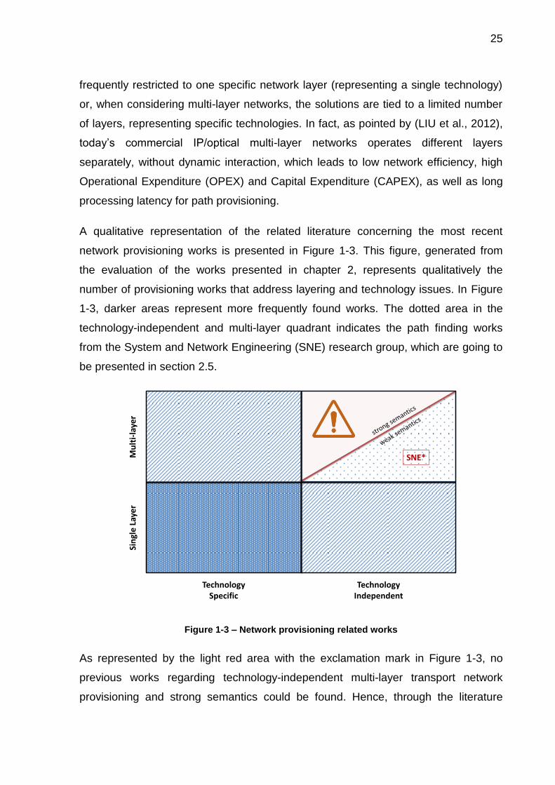
A qualitative representation of the related literature concerning the most recent
network provisioning works is presented in Figure 1-3. This figure, generated from
the evaluation of the works presented in chapter 2, represents qualitatively the
number of provisioning works that address layering and technology issues. In Figure
1-3, darker areas represent more frequently found works. The dotted area in the
technology-independent and multi-layer quadrant indicates the path finding works
from the System and Network Engineering (SNE) research group, which are going to
be presented in section 2.5.
Figure 1-3 – Network provisioning related works
As represented by the light red area with the exclamation mark in Figure 1-3, no
previous works regarding technology-independent multi-layer transport network
provisioning and strong semantics could be found. Hence, through the literature
SNE*Mu
lti-
laye
r
TechnologyIndependent
Sin
gle
Lay
er
TechnologySpecific

26
review presented in chapter 2, it can be concluded that this is a current open issue in
the literature.
1.2 PROPOSAL AND JUSTIFICATION
As presented in subsection 1.1.1, the infrastructure layer is related both to service
provisioning (through its dependence on the infrastructure layer) and to the actual
transport network provisioning (the technology used to implement the infrastructure
layer). Hence, considering the importance of the infrastructure layer to the overall
network provisioning, this thesis focuses on this layer.
Five major problems related to the infrastructure layer provisioning solutions were
pointed in the previous section (subsections 1.1.2 to 1.1.6): (i) the absence of formal
semantics and lack of interoperability, (ii) the need for automation, (iii) the limited
consideration of network equipment, (iv) the technology dependence, and (v) the
limited layering considerations. Regarding these important problems found in the
literature, this thesis research question is: can the use of semantic technologies,
especially ontologies, solve the lack of interoperability in the transport network area
and be the basis for a computational solution that can provision technology-
independent multi-layer transport networks considering the equipment states?
The hypothesis evaluated in this thesis is that the use of a well-founded Ontology
Reference Model of the Recommendation ITU-T G.800 is able to give precise
semantics to the transport network area, allowing interoperability, and that the use of
this Ontology Reference Model in a rigid ontology-based development method can
generate a software that is able to provision technology-independent multi-layer
transport networks considering the equipment states.
Ontologies are proposed in (BERNERS-LEE; HENDLER; LASSILA, 2001) as “a way
to discover common meanings” and have been used in Artificial Intelligence since the
beginning of the 90’s as a synonymous for semantic techniques. Ontologies can be
used in different stages of software development for semantic improvement of the
generated artifacts. The term Ontology came up in Philosophy meaning a systematic
explanation of being. In computing, while used as “an explicit specification of a
27
conceptualization" (GRUBER, 1993), ontologies are used to provide a large number
of resources for intelligent systems as well as for knowledge representation and
reasoning in general (GAŠEVIĆ; DJURIĆ; DEVEDŽIĆ, 2009).
The use of ontologies in network management with the intention of information
integration and interoperability among different management models and languages
is proposed in (VERGARA; VILLAGRÁ; BERROCAL, 2002) and (VERGARA et al.,
2003). Since then, ontologies have been applied to a number of use cases and
research projects (LÓPEZ DE VERGARA et al., 2009). However, interoperation
between different frameworks or management solutions remains an open subject
(MONTEIRO et al., 2014). Ontologies are also used in intelligent network
environments to provide semantics for building knowledge bases, enabling
communication, and reasoning (WONG et al., 2005).
The use of a rigid ontology engineering like the one presented in (GUIZZARDI, 2007)
allows the development of semantically improved ontology artifacts. Different types of
ontology are available for different stages of this ontology engineering. In a first
phase, a conceptual modeling phase, highly expressive languages should be used
(GUIZZARDI, 2007), creating an Ontology Reference Model.
Regarding the weak formalization of the transport network domain and the existing
lack of interoperability, this thesis proposes the creation of an Ontology Reference
Model for this domain. The formalization of this domain allows the interoperability of
management systems for provisioning equipment from multiple vendors. In addition,
the availability of such model is fundamental for the development of intelligent
applications for network provisioning, as the whole configuration management area
relies on a full understanding of the network topology and state (CLEARY; DANEV;
DONOGHUE, 2005).
The proposed Ontology Reference Model should be built with an expressive well-
founded ontology language to define precise semantics and to allow communication,
learning, and interoperation. The OntoUML language (GUIZZARDI, 2005), which has
been successfully employed in a number of industrial projects in several different
domains (ALBUQUERQUE; GUIZZARDI, 2013), is suitable for this purpose.

28
Intending to represent technology-independent multi-layer networks, the OntoUML
Ontology Reference Model must rely on a recognized international standard that
specifies such domain. This thesis proposes the modeling of the Recommendation
ITU-T G.8001 (ITU-T, 2012a), which is the standard that provides a set of constructs
and the semantics that can be used to describe the functional architecture of multi-
layer transport networks in a technology-independent way. The ITU-T G.800 is the
basis for a harmonized set of functional architecture recommendations for specific
layer network technologies (ITU-T, 2012a).
Once the ITU-T G.800 OntoUML Ontology Reference Model is available, in a last
stage of the ontology engineering, versions of this model can be created, resulting in
a computational (or lightweight) ontology. Contrary to reference ontologies,
computational ontologies are not focused on representation adequacy, but are
designed with the focus on guaranteeing desirable computational properties
(GUIZZARDI, 2007).
Considering that the computational artifact resulting from the ontology engineering is
a semantically improved network model with technology-independent multi-layer
transport network concepts, this thesis proposes its use as a knowledge base in a
knowledge-based system (KBS) for network provisioning. Using this knowledge
base, the KBS is able to perform provisioning on this type of network. The use of
Description Logics and semantic web technologies in the development of the
computational provisioning tool allows it to detect inconsistencies and to perform
inferences over the network data, as well as gives to the tool other desired
characteristics, like extensibility and adaptability.
The proposed provisioning tool must be able to perform two different types of
provisioning activities on a technology-independent multi-layer transport network.
First, the network provisioning tool must perform physical circuit provisioning, binding
interfaces from network equipment, considering their different implementation layers,
to provide end-to-end connectivity. This first type of provisioning is here named circuit
1 In order to simplify the reference to the ITU-T recommendations, hereafter they will be called,
indistinctly, Recommendation ITU-T X, ITU-T Rec. X, or simply ITU-T X; where X is substituted by the
corresponding recommendation’s series and number.

29
provisioning. Second, the provisioning tool must perform a virtual circuit provisioning,
enabling information transfer through selected source and destination interfaces of
network equipment. This second type of provisioning is here named connection
provisioning.
A computational provisioning tool helps the network operator to perform network
provisioning, reducing the “human factor”, and, consequently, reducing provisioning
times. For a better use of the network resources, the proposed provisioning tool must
consider the equipment already installed and operational in the network, but also it
should consider the equipment that are available to be used, but that are not installed
or operational.
1.3 OBJECTIVES
This thesis aims to contribute to the network provisioning area, a subarea of the
network management. Its general objective is to develop an ontology-based
provisioning solution for technology-independent multi-layer transport networks. To
accomplish the general objective, three specific objectives (SO) are defined:
SO1: the development of an Ontology Reference Model for technology-
independent multi-layer transport networks based on a recognized
international standard, the Recommendation ITU-T G.800, and built with an
expressive well-founded ontology language to the definition of precise
semantics and to allow communication, learning and interoperation;
SO2: the development of a semantically improved network model for the
provisioning of technology-independent multi-layer transport networks, here
called OWL Computational Ontology. This computational artifact must be
generated from the Ontology Reference Model (SO1) through a rigid ontology
engineering; and
SO3: the development of an ontology-based network provisioning knowledge-
based system that uses the OWL Computational Ontology (SO2) as a
knowledge base. This system must be able to perform circuit provisioning and
30
connection provisioning on a technology-independent multi-layer transport
network, considering the equipment state.
1.4 THESIS STRUCTURE
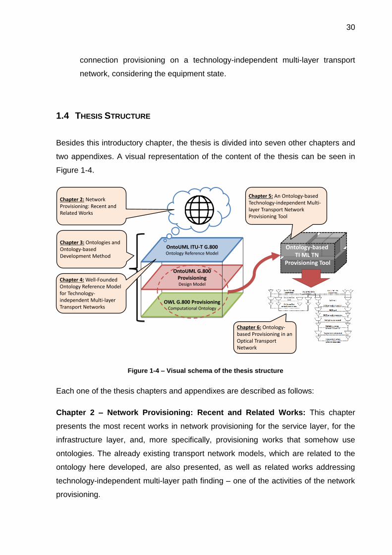
Besides this introductory chapter, the thesis is divided into seven other chapters and
two appendixes. A visual representation of the content of the thesis can be seen in
Figure 1-4.
Figure 1-4 – Visual schema of the thesis structure
Each one of the thesis chapters and appendixes are described as follows:
Chapter 2 – Network Provisioning: Recent and Related Works: This chapter
presents the most recent works in network provisioning for the service layer, for the
infrastructure layer, and, more specifically, provisioning works that somehow use
ontologies. The already existing transport network models, which are related to the
ontology here developed, are also presented, as well as related works addressing
technology-independent multi-layer path finding – one of the activities of the network
provisioning.
OWL G.800 ProvisioningComputational Ontology
OntoUML ITU-T G.800Ontology Reference Model
OntoUML G.800 ProvisioningDesign Model
Chapter 6: Ontology-based Provisioning in an Optical Transport Network
Ontology-based TI ML TN
Provisioning Tool
Chapter 5: An Ontology-based Technology-independent Multi-layer Transport Network Provisioning Tool
Chapter 4: Well-Founded Ontology Reference Model for Technology-independent Multi-layer Transport Networks
Chapter 2: Network Provisioning: Recent and Related Works
Chapter 3: Ontologies and Ontology-based Development Method

31
Chapter 3 – Ontologies and Ontology-based Development Method: This chapter
presents the ontology-based development method used to build the knowledge base
of the transport networks provisioning tool, which comprises an ontology engineering.
This development method is in the context of the Model-Driven Development (MDD)
paradigm, more specifically, it is related to the Model-Driven Architecture (MDA).
Chapter 4 – Well-Founded Ontology Reference Model for Technology-
independent Multi-layer Transport Networks: In this chapter, the
Recommendation ITU-T G.800 is introduced and then the Ontology Reference Model
for technology-independent multi-layer transport networks (SO1), which is based on
the recommendation, is presented. This ontology is later used for the development of
the Network Provisioning Tool.
Chapter 5 – An Ontology-based Technology-independent Multi-Layer Transport
Networks Provisioning Tool: This chapter presents three contributions of the
thesis. First, it presents the OntoUML design model. The design model is used as a
basis for the generation of the provisioning tool knowledge base. This knowledge
base, which is the OWL Computational Ontology (SO2), is the second contribution
presented. Together with the reasoning engine, the knowledge base is the base for
the technology-independent multi-layer transport networks provisioning tool (SO3).
The knowledge-based system’s complete logics are presented in this chapter, as well
as the tool capabilities.
Chapter 6 – Ontology-based Provisioning in an Optical Transport Network: This
chapter presents the application of the provisioning tool in an Optical Transport
Network (OTN) example. The objective of this chapter is to provide a more realistic
use of the provisioning tool, as well as to highlight its use in a specific transport
network technology. After presenting the example settings, the two provisioning
modes available in the tool – i.e., the automatic mode and manual mode – are
presented. Lastly, as performance issues of the provisioning tool are out of the scope
of this thesis, this chapter just briefly addresses this topic.
Chapter 7 – Conclusion: This chapter presents the conclusions of the thesis.
Besides the final discussions, the thesis related material available to readers and

32
future works are presented. A description of the publications that were produced
during the thesis development is also presented.
Chapter 8 – Bibliography: The complete used bibliography is listed in this chapter.
Appendix I – SWRL Rules: This appendix presents the nineteen Semantic Web
Rule Language (SWRL) rules that are part of the OntoUML Design Model and of the
OWL Computational Ontology.
Appendix II – Input TXT Files Structure: The syntax of the provisioning tool input
files is presented with examples in this appendix.

33
2 NETWORK PROVISIONING: RECENT AND RELATED
WORKS
In this chapter, we are going to present a study on recent works concerning network
provisioning, as well as discuss related works. Based on Figure 1-3, the distribution
of this chapter’s content is represented in Figure 2-1.
Figure 2-1 – Content distribution of chapter 2
Many different network configuration operations can be classified with the term
“provisioning”. As an example, when performing a literature research, one will find
different provisioning strategies for Quality of Service (QoS), bandwidth, resource
allocation, etc. Intending to present a broad overview of the recent works on the area,
we are going to use once more the two-layer network abstraction presented in Figure
1-2. In section 2.1 and in section 2.2, we are going to present, respectively, recent
studies in service provisioning and in infrastructure provisioning. After that, in section
2.3, we are going to explore works that have already somehow used ontologies for
network provisioning.
Although the works presented in these three initial sections are not directly related to
the one presented in this thesis, they are in the same area and address current
network provisioning problems. By providing these works, we would like to highlight
the relevance of this area, as well as to situate the reader in the most recent
Multi-layer
TechnologyIndependent
Single Layer
TechnologySpecific
Sections 2.1 to 2.3
Sections 2.4 and 2.5
Unavailable Literature

34
contributions to network provisioning. The works presented in these three sections
are located in the blue area in Figure 2-1.
Regarding related works, in section 2.4, we first present other network models
available in the literature, explaining their focus and main concerns. Finally, the most
related works to the one presented in this thesis, which addresses path finding in
technology-independent multi-layer transport networks, are presented in section 2.5
and compared to the work developed here. The related works, especially the ones
presented in section 2.5, are located in the green area in Figure 2-1.
In conclusion, we could not find works that could be positioned in the red area of
Figure 2-1. The work developed in this thesis is situated in this still unexplored area
of the literature.
2.1 SERVICE LAYER PROVISIONING
The review performed by (DUAN; YAN; VASILAKOS, 2012) shows that recent
evolution of service management in telecommunications has followed a path toward
network virtualization; that is, decoupling service provisioning from data transport and
exposing network infrastructure through resource abstraction. The Service-Oriented
Architecture (SOA) principle and Web Service technologies have been applied to
facilitate virtualization in telecom systems (DUAN; YAN; VASILAKOS, 2012).
The increasing attention to network virtualization is supported by a recent study
described in (MATERA; LISTANTI; PIÓRO, 2015) on trends in network planning to
decrease the CAPEX/OPEX costs. In such study, among ten studied papers
addressing recent challenges in communication network planning, two of them
concern resource provisioning in virtualized networks. They listed as trends (i) the
provisioning of customized and on-demand resources for multiple service providers
with different Quality of Service requirements in (SEDDIKI; FRIKHA; SONG, 2015),
and (ii) the design and implementation aspects of a network resource provisioning
module designed for the Polish Initiative of Future Internet called System IIP in
(GOZDECKI et al., 2015).

35
The first work cited by (MATERA; LISTANTI; PIÓRO, 2015) proposes a two-stage
approach based on non-cooperative games focused on provisioning and managing
the physical resources in a virtualized network infrastructure (SEDDIKI; FRIKHA;
SONG, 2015). The second cited work proposes a set of novel linear programming
optimization models for network resource provisioning designed to minimize the
network resource consumption, either bandwidth or node’s computational power, as
well as to maximize the residual capacity (GOZDECKI et al., 2015).
This demand for service provisioning is reflected by the standardization
organizations, which have released different standards in this area, like frameworks
for service management and operation by aggregating network capabilities and
service management functions in a common platform. Specifications in this area
include the Open Mobile Alliance (OMA) Open Service Environment (OSE) (MAES,
2007) and the TM Forum Service Delivery Framework (SDF) (HUANG, 2009).
In addition, according to (DUAN; YAN; VASILAKOS, 2012), there has been a
motivation to organize the services/applications offered by various networks on an
overlay that allows service providers to offer rich services. Toward this objective, the
Institute of Electrical and Electronics Engineers (IEEE) recently developed the Next
Generation Service Overlay Network (NGSON) standard (LEE; KANG, 2012), which
specifies context-aware, dynamically adaptive, and self-organizing networking
capabilities, including both service level and transport level functions that are
independent of the underlying network infrastructure (DUAN; YAN; VASILAKOS,
2012).
SOA has been widely adopted in cloud computing via the paradigm of Infrastructure-
as-a-Service (IaaS) (DUAN; YAN; VASILAKOS, 2012). The provisioning of virtual
resources in future networks relying on the IaaS principle is addressed in (HOUIDI et
al., 2011b), which uses exact and heuristic optimization algorithms for the
provisioning of virtual networks involving multiple infrastructure providers. Their study
assumes the emergence of new actors such as virtual network providers acting as
brokers requesting virtual resources on behalf of users. Resource matching, splitting
(solved in the paper with the use of both max-flow min-cut algorithms and linear
programming techniques), embedding (formulated and solved as a mixed integer
program), and binding steps required for virtual network provisioning are proposed

36
and evaluated (HOUIDI et al., 2011b). In a previous work, described in (HOUIDI et
al., 2010), the same authors had investigated the problem of adaptive virtual network
provisioning and developed an algorithm for adaptive infrastructure resource
allocation to support virtual networks (DUAN; YAN; VASILAKOS, 2012).
According to (DUAN; YAN; VASILAKOS, 2012), service-oriented network
virtualization enables the Network-as-a-Service (NaaS) paradigm that allows network
infrastructure to be exposed and utilized as network services, which can be
composed with computing services in a cloud environment. Therefore, the NaaS
paradigm may greatly facilitate a convergence of networking and cloud computing
(DUAN; YAN; VASILAKOS, 2012).
Cloud service provisioning across multiple cloud providers is addressed in (HOUIDI
et al., 2011a), which developed an exact algorithm to efficiently split the cloud
requests among the multiple cloud platforms with the aim of decreasing the cost for
customers. Still concerning cloud computing, (CALHEIROS et al., 2011) proposed
the CloudSim, an extensible simulation toolkit that enables modeling and simulation
of cloud computing systems and application provisioning environments. The
CloudSim implements generic application provisioning techniques that can be
extended with ease and limited effort (CALHEIROS et al., 2011).
An application-aware virtual data center provisioning method for distributed data
centers (DC) enabled by coordinated virtualization of optical Orthogonal Frequency
Division Multiplexing (OFDM) network and DCs is proposed in (PENG et al., 2013).
The coordinated virtualization of optical network and Information Technology (IT)
resources in DCs is developed as a key part of the provisioning method (PENG et al.,
2013). This work targets future cloud platform that deploys advanced optical
transport technologies for interconnecting remote DCs.
The service provisioning technology dependence, as well as the difficulty to divide
the two network abstraction layers here adopted, can be observed in (WANG et al.,
2014), which presents a flexible virtual optical network provisioning procedure for
distance-adaptive flex-grid optical networks. Their work, which aims at maximizing
spectrum utilization efficiency, is in the context of Software-defined Optical Network
(SDON). This technology relies on optical network virtualization, which enables

37
network service providers to provision multiple coexisting and isolated Virtual Optical
Networks (VON) over the same physical infrastructure (WANG et al., 2014). Since a
lightpath is a special instance of a VON, they claim that the VON service provisioning
system used by a SDON service provider has backward-compatibility to traditional
lightpath provisioning.
2.2 INFRASTRUCTURE LAYER PROVISIONING
Concerning the infrastructure layer, the most recent works are focused on the Dense
Wavelength Division Multiplexing (DWDM) networks, which are the most widely used
transport technology nowadays (LIU et al., 2006). We can divide the works related to
this network abstraction layer into two categories: discussions about control plane
solutions (subsection 2.2.1) and lightpath provisioning strategies (subsection 2.2.2).
Before presenting the diverse provisioning techniques, we must say that multi-layer
provisioning is addressed in some works, however always dealing with technology-
specific layers. For example, (LEHMAN et al., 2007) defines its multi-layer aspect as
referring to the fact that end-to-end service may be instantiated via a data plane path
that traverses multiple different network elements that belong to different technology
layers. This situation can be seen in Figure 2-2, which shows an example from
(DOVERSPIKE; YATES, 2012) representing five layers supporting the provisioning of
two 10-Gb/s circuits. Note that all layers in Figure 2-2 are from specific technologies.

38
Figure 2-2 – Sublayering within the optical layer. From (DOVERSPIKE; YATES, 2012)
As another example, the work presented in (DOUCETTE; GROVER; GIESE, 2007)
defines a multi-layer design and operation strategy for multi-service and multi-layer
survivable traffic engineering and bandwidth management. In this specific work, the
term “multi-layer” is used to refer to the fact that the strategy there defined deals with
two distinct layers: Wavelength Division Multiplexing (WDM) and IP/Multi-Protocol
Label Switching (MPLS). The same happens with the work presented in (KOZAT;
KOUTSOPOULOS; TASSIULAS, 2006). This work performs QoS provisioning
considering wireless multi-layers, which are the routing layer, the medium access
control layer, and the physical layer.
2.2.1 Control Plane Discussions
A first category of works regarding provisioning in optical networks deals with the
control plane technology, architecture, and design. A control plane is a key enabling

39
technique for dynamic and intelligent end-to-end path provisioning in optical networks
(LIU et al., 2013).
The Generalized Multi-Protocol Label Switching (GMPLS), developed by the Internet
Engineering Task Force (IETF) as a generic network control plane framework, is
used for managing physical path and core tunneling technologies of the Internet and
telecom service providers (AZODOLMOLKY et al., 2011). The GMPLS control plane,
due to its support for various optical transport technologies as well as its capability for
dynamic and on demand lightpath provisioning, is widely being considered by
operators as the control plane of their next generation core optical networks
(AZODOLMOLKY et al., 2011).
Architecture and design considerations associated with the development of a control
plane capable of dynamic provisioning in heterogeneous multi-domain, multi-layer,
multi-service hybrid network environments are presented in (LEHMAN et al., 2007).
The vision for these hybrid networks is to enable flexible and dynamic provisioning of
end-to-end network services (LEHMAN et al., 2007). This work proposes a
framework for addressing the heterogeneous nature of the hybrid networks via the
development of a flexible set of mechanisms which address the key control plane
functions of routing, path computation, and signaling (LEHMAN et al., 2007). An
interoperable set of constructs is proposed based on GMPLS and Web Service for
seamless provisioning across heterogeneous data and control planes (LEHMAN et
al., 2007).
Considering Elastic Optical Networking (EON), some studies have started to design a
GMPLS-based control plane (LIU et al., 2013). Despite massive progress, it should
be noted that such studies mainly focused on the control of the optical layer (LIU et
al., 2013).
Authors like (LIU et al., 2012) claims that, despite the development and
standardization efforts, with different interconnection models proposed for a GMPLS-
based Unified Control Plane (UCP) in multi-layer optical networks, there are no
commercial deployments of these models, and the debate for their practicability in a
real operational scenario grows in intensity (LIU et al., 2012). Due to its distributed
nature, the number of protocols, and the interactions among different

40
layers/granularities, the GMPLS UCP becomes overly complex (LIU et al., 2012).
However, recent studies (MARTINEZ; CASELLAS; MUNOZ, 2012) have validated
the application of a GMPLS-based unified control plane for controlling a multi-layer
network composed of both packet – Multi-Protocol Label Switching Transport Profile
(MPLS-TP) – and optical switching – Wavelength Switched Optical Network (WSON)
– technologies (LIU et al., 2013). Although more mature and intelligent, a GMPLS-
based control plane may not be an ideal solution for the deployment in a real
operational scenario due to its distributed nature and high complexity, especially for a
unified control functionality in IP and optical multi-layer networks (LIU et al., 2013).
Criticisms over GMPLS, especially for the representation of multi-layer networks and
for the development of path finding applications in this kind of networks, can be found
in (DIJKSTRA, 2009; DIJKSTRA et al., 2008).
More recently, OpenFlow has been proposed as a control framework that supports
programmability of network functions and protocols (i.e., software defined
networking) by decoupling the data plane and the control plane, which are currently
vertically integrated in many networking equipment (e.g., routers, switches, access
points) (AZODOLMOLKY et al., 2011; MCKEOWN et al., 2008). The mediation
between control plane segments and layer boundaries, allowing communication and
interoperability to support transport networks with multiple administrative and
technology segments, is often a manual process that Software Defined Networking
(SDN) could automate (GRINGERI; BITAR; XIA, 2013). OpenFlow adopts the
concept of flow based switching and network traffic control for intelligent, user
controlled, and programmable network service provisioning with the capability to
execute any user defined routing, control, and management application in its
controller (AZODOLMOLKY et al., 2011).
In (AZODOLMOLKY et al., 2011), a software-defined packet over optical networks
solution based on the OpenFlow and GMPLS control plane integration is
demonstrated. They proposed an overlay model that extends the functionality of a
typical OpenFlow controller in a way to properly interface with GMPLS control plane
(AZODOLMOLKY et al., 2011).
The OpenFlow protocol, which has been previously addressed as a unified control
plane for multi-layer multi-granularity optical networks (LIU et al., 2012), provides the

41
maximum flexibility for operators to control a network and arguably matches carriers’
preference given its simplicity and manageability (LIU et al., 2012, 2013). In light of
this, an OpenFlow-based control plane to achieve dynamically optical path
provisioning and IP traffic offloading in an EON, referred to as OpenSlice, was
presented in (LIU et al., 2013).
The control plane is also an interest research topic in the mobile network
provisioning. As an example, the work presented in (HOFFMANN; STAUFER, 2011)
provides concrete extensions of existing control plane protocols and interfaces for a
layer-independent, vendor-independent, and domain-independent provisioning, and
operation of virtual networks for future mobile networks.
2.2.2 Recent Studies on Lightpath Provisioning
On the algorithmic provisioning side, a multitude of DWDM Routing and Wavelength
Assignment (RWA) and survivability schemes have evolved (LIU et al., 2006). As
DWDM technology proliferates, there is a pressing need to develop more advanced
lightpath provisioning algorithms for distributed multi-domain settings (LIU et al.,
2006). This position is supported by (CHAMANIA; JUKAN, 2009), which defends that
efficient provisioning of high-bandwidth connections between the multiple domains
separated by technologies, administrative rules, and control and signaling concepts
is an open challenge.
Today’s optical circuit provisioning process in large carrier networks is presented and
discussed in (DOVERSPIKE; YATES, 2012). Their work lists four broad categories of
provisioning steps in the core segment, which are:
1. Manual: installation personnel visit central office, install cards and plug-ins,
and fiber them to the patch panel.
2. Manual: installation personnel visit central office and cross connect ports via
the patch panel.
3. Semi-automated: provisioners request optical cross connects via a command
line interface or element management system.
42
4. Fully automated: an operation support system is fed by a circuit path from a
network planner or planning tool. Then, this system automatically sends
optical cross-connect commands to the command line interface or element
management system.
They also present that carriers are mostly semi-automated provisioning today, and in
many cases, a circuit order may require steps from all four categories
(DOVERSPIKE; YATES, 2012).
A survey of inter-domain provisioning solutions for the next generation optical
networks is presented in (CHAMANIA; JUKAN, 2009), however multi-layer issues are
outside the paper’s scope.
While previous works – e.g., (YURONG HUANG; HERITAGE; MUKHERJEE, 2005) –
intend to design intelligent connection-provisioning algorithms that improve network
performance, the most recent works are focused in the provisioning of elastic optical
networks and in considerations about energy efficiency.
Elastic Optical Networking is an emerging candidate to achieve more cost-effective
optical networks, as they achieve more spectrally efficient networking in the optical
layer employing an adaptive bandwidth allocation scheme with fine and flexible
frequency slots (SONE et al., 2011). On EON, the Route and Spectrum Assignment
(RSA) problem for provisioning paths could be a concern for network operations,
similar to the RWA problem in conventional optical networks (SONE et al., 2011).
The elastic optical path is achieved using OFDM technology. According to (ZHU et
al., 2013), the provisioning of elastic optical OFDM networks has started to attract
research interests just recently.
According to (SONE et al., 2011), the operational scenarios for elastic optical
networking are broadly classified into incremental, static, and dynamic provisioning.
As can also be seen in (SONE et al., 2011), for dynamic provisioning (where the
duration of a path is considered), (TAKAGI et al., 2011) presented a distance-
adaptive RSA algorithm for dynamic traffic; and, regarding static provisioning (where
entire demands are considered at the same time), (CHRISTODOULOPOULOS;
TOMKOS; VARVARIGOS, 2010) provided an Integer Linear Programming
formulation. The RSA problems for incremental provisioning (where a permanent

43
path is provisioned on a one-by-one basis) is addressed in (SONE et al., 2011) that
proposes the Maximize Common Large Segment RSA algorithm, which employs a
metric that quantifies the consecutiveness of the common available spectrum slots
among relevant fibers.
A spectrum-sliced elastic optical path network (SLICE) architecture has been recently
proposed as an efficient solution for a flexible bandwidth allocation in optical
networks (JINNO et al., 2009). This architecture is defined as a very promising
solution for 100 GB/s and beyond connection provisioning in optical networks in
(KLINKOWSKI; WALKOWIAK, 2011).
Once again, demonstrating the weak separation between the two abstraction layers,
service provisioning in EON is also present in the literature. In the context of a
Coherent Optical OFDM optical network, (SHEN; YANG, 2011) evaluates how
flexible wavelength and spectrum assignment can help lightpath service provisioning,
while (ZHU et al., 2013) addresses the dynamic service provisioning in EON with
hybrid single-/multi-path routing.
Considering that the traffic supported by the Internet has grown enormously over the
last few years and that it is virtually certain that this traffic growth will continue both in
the near and long term future (JIRATTIGALACHOTE et al., 2011), the interest in the
energy consumption of communication networks has risen in recent years (MONTI et
al., 2011). In such scenario, “green” strategies are desirable to help service providers
operate their networks and provision services in a more energy efficient way (XIA et
al., 2011).
Green provisioning strategies for optical WDM networks are addressed by (XIA et al.,
2011), where the authors developed a power-aware provisioning scheme to improve
the energy efficiency of the networks. Connection provisioning is addressed by
(JIRATTIGALACHOTE et al., 2011), which presents dynamic provisioning strategies
for energy efficient WDM networks with dedicated path protection. Their focus is on
the network’s energy consumption, as they investigate the energy savings in path
protection. Lastly, concerning energy-efficient lightpath provisioning in static WDM
networks with dedicated path protection, (MONTI et al., 2011) proposes a scalable

44
and efficient heuristic that chooses the route of the working and protection lightpaths
with the aim to maximize power saving.
2.3 ONTOLOGY-BASED PROVISIONING
In the last decade, many works have used ontologies, especially lightweight
ontologies, as a solution or as part of the solution to service provisioning. An
interesting paper that presented study cases and lessons learned for ontology-based
network management from diverse research projects can be found in (LÓPEZ DE
VERGARA et al., 2009). Among the presented studies, one concerns the use of
ontologies for network provisioning. The project reported by (LÓPEZ DE VERGARA
et al., 2009) is about a home gateway that autonomously provisions services to the
users, configuring the associated devices when a user queries for a new service.
This project, presented in (LÓPEZ DE VERGARA et al., 2008) and in (LOZANO et
al., 2008), is related to the use of ontologies in a self-managed system as a way to
model the information to be used in that system. The used ontology was defined to
share the knowledge between both the telecommunications company operator and
the home gateway (LÓPEZ DE VERGARA et al., 2009).
Ontological modeling of pervasive services’ lifecycle as a result of the management
necessities in broadband convergence networks is addressed in (SERRANO et al.,
2008). This paper presents research challenges for facilitating autonomic
management, defining aspects in the organizational view of service lifecycle, and for
the control of pervasive services functions. A brief comparison of a management
system using policies without semantic enrichment and using ontology-based policies
is also depicted in (SERRANO et al., 2008).
A context-aware middleware system that facilitates diverse multimedia services in-
heterogeneous network environments by combining an adaptive service-provisioning
middleware framework with a context-aware multimedia middleware framework is
presented in (ZHOU et al., 2010). In this work, the authors adopt the Web Ontology
Language (OWL) to enable expressive context descriptions and data interoperability
of context.

45
Recently, The Global City Indicators (GCI) Telecommunication & Innovation ontology,
defined in (FORDE; FOX, 2015), which intends to represent the definitions of the ISO
37120 Telecommunication & Innovation theme indicators, has a provisioning model
as one of its composing parts. Provisioning is an important concept for this work
because the GCI Telecommunication & Innovation indicators are all based on
measuring the number of telecom services to which residents in a city are connected.
By accounting for the preparation process necessary to develop a network to provide
services the GCI Telecommunication & Innovation ontology will be able to account
for new network services introduced over time (FORDE; FOX, 2015). The OWL
ontology proposed in the project makes use of another OWL ontology developed in
(KNACKSTEDT et al., 2008), which models services based on human requirements.
They claim that, inside their context, the ontology presented in (KNACKSTEDT et al.,
2008) is best used as a reference model that can address issues surrounding
provisioning (FORDE; FOX, 2015).
Concerning service provisioning and an economic perspective with respect to service
allocation and price determination, (BLAU et al., 2008) has three main contributions.
First, they introduce an ontology framework, which is part of a tool that visually and
semantically supports service providers in the process of service mashup planning.
Second, their ontology-based framework for modeling services provides concepts for
specifying functional and non-functional service properties with a special focus on
economic aspects. And finally, the result of the planning process is a graph topology
representing the complex service and its potential sub-services, their configurations
and reasonable interrelations that fulfill an overall functionality (BLAU et al., 2008).
Ontologies have a close relation to the use of intelligent computational agents. In
(PODOBNIK; TRZEC; JEZIC, 2007), ontologies are used in agent-based context-
aware service provisioning systems for next-generation networks. Ontologies and
agents were also used in (VRDOLJAK et al., 2009), which proposed an ontology-
based middleware for enhancing group-oriented mobile service provisioning, called
AMiGO-Mob.
Ontologies are also used in the proposal for ubiquitous service provisioning, in
(SANCHEZ-LORO et al., 2009). In this work, ontologies are used to provide a
common syntax and semantics to network nodes. The work presented in (ABOSI;

46
NEJABATI; SIMEONIDOU, 2009), concerning a service composition mechanism for
the future optical Internet, has an ontology translator module. This ontology translator
module uses an ontology to describe semantics of information to support service
discovery and composition. According to (ABOSI; NEJABATI; SIMEONIDOU, 2009),
the use of Resource Description Framework (RDF) and OWL as knowledge
representation languages facilitate unambiguous discovery of services.
For other types of network, we can also find ontology proposals to manage services.
For multi-service IP networks, (RODRIGUES et al., 2012) proposes an ontological
model – built in OWL and Semantic Web Rule Language (SWRL) – intending to
provide an improved semantic description of network services for interoperability and
self-management. For the highly relevant Internet of Things, lightweight ontologies
are used in a system architecture that, among other functionalities, provides on-
demand service provisioning (GUINARD et al., 2010). A framework for service
provisioning in virtual sensor networks is presented in (SARAKIS et al., 2012).
Resource description using ontologies can also be found in many other areas, like
Low Carbon Grid Networks (DAOUADJI et al., 2010).
An important usage of ontologies in network provisioning consists in the ontology-
based network description languages, like the Network Description Language (NDL)
(VAN DER HAM et al., 2007) and the Network Markup Language (NML) (HAM et al.,
2013). The former language aims to describe an overview of network topology in
order to provide a common semantic to the applications, the network, and the service
providers for unambiguous communications among them (DUAN; YAN; VASILAKOS,
2012). The latter language is an extensible schema to describe network topologies
and capabilities – it was used with success to define an information model for service
discovery and provisioning in (FAJJARI; AYARI; PUJOLLE, 2010). Another example
of language in this class is the Network Resource Description Language (NRDL)
(CAMPI; CALLEGATI, 2009), developed in order to facilitate abstraction of
networking resources with a focus on the interaction among network elements rather
than on individual network objects (DUAN; YAN; VASILAKOS, 2012). According to
(DUAN; YAN; VASILAKOS, 2012), this change of emphasis enables the NRDL to
give a better description of the resources for network service provisioning; thus
expressing network service abstraction. These network description languages are
addressed in this thesis section 2.4.

47
Finally, an important ontology-based project is the Generalized Architecture for
Dynamic Infrastructure Services (GEYSERS) (ESCALONA et al., 2011). The
GEYSERS concept aims to define and implement a novel service provisioning
architecture, capable of provisioning optical network and IT resources for end-to-end
service delivery (ESCALONA et al., 2011). One of the GEYSERS’s modules utilizes a
semantic resource description and information modeling mechanism, based on NDL
and on Virtual Resources and Interconnection Networks Description Language
(VXDL) (KOSLOVSKI; PRIMET; CHARÃO, 2009) for describing the underlying
physical infrastructure (e.g., switching capabilities). This ontology-based module
allows the creation of virtual infrastructures using the virtualized resources and a
dynamic on-demand re-planning of the virtual infrastructure composition
(ESCALONA et al., 2011).
2.4 EXISTING TRANSPORT NETWORK MODELS
Network models can help users and applications to understand the complexity of
networks (especially multi-layer networks, where the configuration of the network can
be changed dynamically at multiple layers), and can support diverse applications,
such as path finding, scheduling, fault isolation, and visualization (DIJKSTRA et al.,
2008). Regarding the importance of models, the usage of data structuring models
built with semantic web technologies, especially lightweight ontologies, is found in
many different works. These works claim that the use of these technologies can
directly solve interoperation problems. However, the direct use of computational
languages for building these interoperation artifacts can lead to lack of semantics
and, hence, to problems like false integration – see, for example, the false agreement
problem (GUARINO, 1998).
Considering network management, the lack of a formal semantics in models was
presented in (VERGARA et al., 2003) and (VERGARA; VILLAGRÁ; BERROCAL,
2004). According to them, different management models (SNMP, CMIP, CIM/WBEM,
and Corba) could be correlated. In their work, a heuristic (human driven) mapping
process was used to establish a semantic equivalence between these models. As a
result, (VERGARA; VILLAGRÁ; BERROCAL, 2002) presented a network

48
management metamodel. The term ontology, meaning taxonomy or common
information model, has been used in the network management context since then
and interoperability has become an issue in network management, as pointed in
(WONG et al., 2005).
Autonomic management and self-management researchers have taken ontology first
as information taxonomy (VERGARA; VILLAGRÁ; BERROCAL, 2002), then as a
data representation standard (QUIROLGICO; MILLS; MONTGOMERY, 2003) and
later as endogenous interoperability solution (WONG et al., 2005). Thus,
interoperability is reached only inside the proposed solution, i.e., interoperability just
exists if the communicating parts implement the proposed framework or model. Even
so, ontology as an interoperability tool is frequently used as an approach to improve
autonomy and self-features of network management solutions (SERRANO; SERRAT;
STRASSNER, 2007). Interoperation between different autonomic solutions
(exogenous interoperability) remains an open subject (MONTEIRO et al., 2014).
The interesting work presented in (HAM et al., 2014) provides a taxonomy of current
and past network modeling efforts over the last few years. This work concludes that,
on the one hand, management models have changed less, given they are all aimed
at specific applications, and target very specific use-cases or tools; and, on the other
hand, monitoring, general, and Future Internet models have all evolved significantly.
According to (HAM et al., 2014), there is a trend towards not only describing the
network, but connected devices as well. This is especially current given the many
Future Internet projects, which are combining different models and resources in order
to provide complete virtual infrastructures to users (HAM et al., 2014).
One basic rule that holds for both the current Internet and the upcoming Future
Internet platforms is presented in (HAM et al., 2014): the design, planning,
management, and monitoring of the network rely on the knowledge of its topology,
expressed as network models. A network topology provides information on the
location of devices and on the connections between them; this information, in turn,
gives a view of the physical and logical structure of the network. Topology
information needs to be available to all devices within the network to operate
properly, to external tools that act on the network, and to applications that use the

49
network (HAM et al., 2014). Three main challenges for network models are pointed in
(HAM et al., 2014):
1. handling different abstraction levels;
2. managing multi-domain communication and path setup;
3. integration with computing-network-storage-planning services.
An important mechanism for managing complexity is the creation of an abstract
model, a step which, according to (HAM et al., 2014), has been undertaken in
computer networks. According to (HAM et al., 2014), works that define general
network models are NDL v2, NML, NDL-OWL, Networking Over Virtualized
Infrastructures (NOVI), GEYSERS, and Infrastructure and Network Description
Language (INDL). Table 2-1 summarizes the models’ main purpose, scope, and
language type. The next paragraphs use text adapted from (HAM et al., 2014) to
present briefly all these initiatives.
Table 2-1 – Overview of the existing network models. Adapted from (HAM et al., 2014)
Model Name Main Purpose Scope Representation Language
NDL General Network RDF
NML General Network XML + OWL
NDL-OWL General Network + Comp & Storage OWL
NOVI/GEYSERS/INDL General Network + Comp & Storage OWL
NDL, originally presented in (VAN DER HAM et al., 2006), is a method of using RDF
to describe networks. Its original model (v1) was simple and intended to describe
devices, interfaces, and their connections. Using ideas from ITU-T G.805, NDL was
extended to its version 2, which is able to describe multi-layer networks generically
(DIJKSTRA et al., 2008; VAN DER HAM et al., 2008). More information about the
NDL underlying concepts and other works from the same research group, especially
the ones regarding multi-layer path finding, are presented in section 2.5.
The ITU-T G.805 and the NDL are the models on which NML is based. NML (HAM et
al., 2013) is a generic network model that can be used for describing measurements,
monitoring, topologies, and also requests. To support different applications, NML has
two different data models, one in eXtensible Markup Language (XML) and other in
OWL.

50
The Network Description Language OWL (NDL-OWL) is an extension of NDL v2 to
the OWL syntax developed in the Open Resource Control Architecture-Breakable
Experimental Network (ORCA-BEN) project (BALDINE et al., 2009; XIN et al., 2011),
within the Global Environment for Network Innovations (GENI)2 initiative. NDL-OWL
also extends NDL with more virtualization and service description features to
describe their infrastructures. These descriptions are then used in the client software
to describe requests, but also in the management software to match the requests
with the available infrastructure.
The NOVI project aims to federate Future Internet platforms and one of the
challenges of the NOVI information model is to interact with different platforms (HAM
et al., 2011a, 2011b). The NOVI ontology suite allows a complete semantic
description of a Future Internet federation. NOVI has ontologies for the infrastructure,
but also for monitoring tools and results, as well as policy aspects and rules.
The GEYSERS Information Modeling Framework (IMF), intends to provide an
information model for the Logical Infrastructure Composition Layer (GARCÍA-ESPÍN
et al., 2012). One of the key innovations of GEYSERS is to enable virtualization of
optical infrastructures. This layer is the element responsible for managing physical
resource virtualization and composing Virtual Infrastructures. These are then offered
as a service within the GEYSERS architecture.
INDL (GHIJSEN et al., 2012, 2013) is an evolution of the Network Description
Language, combined with the experiences in NOVI and GEYSERS. In INDL, the
general model from NML was added to capabilities to describe the virtualization of
nodes and infrastructure. According to (HAM et al., 2014), the resulting model of
INDL is actually not that different from the model in NOVI and GEYSERS, but it
provides a more reusable model available for other Future Internet platforms. Figure
2-3 shows an overview of the described information models and shows how they
have influenced each other.
2 https://www.geni.net/

51
Figure 2-3 – Overview of the existing information models and their influences. Adapted from
(HAM et al., 2014)
None of the network models presented in this section were built with the use of an
ontology engineering, like the one presented in (GUIZZARDI, 2007). Instead, the
models were built directly using computational languages, like XML, RDF, and OWL.
As can be seen in (GUIZZARDI, 2005, 2007; GUIZZARDI et al., 2009), this category
of languages are not able to correctly represent a domain because of their
computational restrictions. In addition, Figure 2-3 emphasizes the special importance
that the ITU-T G.805 has in this context, as being the reference for many other
network models. It has already been demonstrated, in (BARCELOS et al., 2011), that
the ITU-T G.805 has ontological deficiencies in its natural language description, and
it has also been demonstrated that its formal specification is also not capable to
capture all the domain nuances (BARCELOS et al., 2016). The ITU-T G.805 became
the basis of NDL, as pointed in (VAN DER HAM et al., 2008) and, by inheritance, as
can be seen in Figure 2-3, it is also part of the languages that extend NDL, which are
NML, NDL-OWL, NOVI, GEYSERS, and INDL. A recommendation with ontological
deficiencies will propagate these problems to all other recommendations, models,
and languages that use it as a basis (BARCELOS et al., 2016).
The ITU-T G.800 Ontology Models are built with a strict method (that is going to be
presented in section 4.3), which guarantees better semantic representation and the

52
elimination of ontological deficiencies. The use of the Ontology Reference Model to
create computational models (e.g., via automated transformation, a process free from
human errors) results in a network computational (information) model with improved
knowledge representation and reasoning capabilities.
The first two of the three desired properties listed by (HAM et al., 2014) are
accomplished by the ITU-T G.800 Ontology Reference Model. The model can handle
different abstraction levels using a three layered ontology level (Site, Equipment, and
ITU-T G.800). As being based on the Recommendation ITU-T G.800, it can manage
multi-domain communication and path setup. However, the current knowledge base
(generated from the Ontology Reference Model) does not have the third desired
point, which is the integration with computing-network-storage-planning services.
This third point can be thought as a future work. This characteristic could be included
as a new ontology layer (to be coupled with the already existing ones) or as the
extension of one of the already presented layers in a future version of the knowledge
base.
2.5 PATH FINDING IN TECHNOLOGY-INDEPENDENT MULTI-LAYER NETWORKS
Regarding the provisioning of technology-independent multi-layer networks, we can
assert that the most related works are the multi-layer path finding ones, developed by
the System and Network Engineering (SNE) research group, from the University of
Amsterdam3.
One of this groups’ most important works is the NDL, originally presented in (VAN
DER HAM et al., 2006). In its first version, NDL was a simple language only capable
to describe single layer networks. The group, beginning with the study of the
Recommendation ITU-T G.805 presented in (DIJKSTRA et al., 2007), developed, in
(DIJKSTRA et al., 2008), a network model based on the ITU-T G.805. Incorporating
the proposed network model, the NDL became able to describe multi-layer networks
(DIJKSTRA et al., 2008). With the multitude of uses of the NDL and with its extension
3 https://ivi.fnwi.uva.nl/sne/

53
to other languages (according to Figure 2-3, the languages are NML, NDL-OWL,
NOVI, GEYSERS, and INDL), the proposed network model based on the ITU-T
G.805 presented in (DIJKSTRA et al., 2008) acquires a crucial importance.
2.5.1 An ITU-T G.805 Network Model and Algebra for Connections
In (DIJKSTRA et al., 2008), the authors have shown that multi-layer networks cannot
be represented as simple graphs because this type of representation only provide
two basic building blocks: edges and vertices. According to the authors, multi-layer
computer networks have at least three building blocks: links, devices, and
adaptations – perhaps four, when counting interfaces. In addition, even though cited
as candidates for representation of multi-layer networks, the GMPLS and the
Common Information Model (CIM) (as well as network simulators) are classified in
(DIJKSTRA et al., 2008) as technology-specific models. In fact, the authors report
that the few models that consider multiple layers are often geared towards very
specific cases. Therefore, just like in this thesis, the mentioned work proposes a
model for technology-independent multi-layer computer networks – this model is later
called an ontology in (DIJKSTRA et al., 2009). Their model, build with the intention to
support a path finding function, is mainly based on the ITU-T G.805 (hence, only
covers circuit-switched networks), but also on the GMPLS label concept (for solving a
practical problem concerning identification of connections).
Besides the network model, (DIJKSTRA et al., 2008) also presents a simple algebra
that can be used to verify the validity of network connections. Both the model and the
algebra have been implemented in a syntax and network tool, a software framework
that is able to find valid paths in multi-layer networks.
The results of (DIJKSTRA et al., 2008) can be directly associated with the Ontology
Reference Model for technology-independent multi-layer transport networks that is
one of the objectives of this thesis. Their proposed network model is related to the
ontology model and their algebra for connections is associated with the model
inference rules – no restriction rules were presented in (DIJKSTRA et al., 2008). The
network model proposed in this thesis, however, intends to be a reference model for
the area, providing sound formalization for the domain without considering

54
computational restrictions and possible applications. The model proposed in
(DIJKSTRA et al., 2008) was developed with the intention to be coupled to NDL and
to provide the basis for domain-specific computational applications, like the path
finding proposed by the same research group in (DIJKSTRA et al., 2009).
Application-oriented models are well suited for the applications they are built for,
however, they lack in expressivity when considering the whole domain and usually
are a source of problems when used for semantic interoperation (GUIZZARDI, 2005,
2007).
To show that the network model and algebra presented in (DIJKSTRA et al., 2008)
have practical applications, a Resource Description Framework Schema (RDF-S)
was created to extend the NDL. The resulting NDL multi-layer schema describes the
basic concepts of network layers and allows descriptions of actual technologies.
According to the authors, the schema was able to describe successfully WDM, Fiber,
Synchronous Optical Networking (SONET), Synchronous Digital Hierarchy (SDH),
Asynchronous Transfer Mode (ATM), Ethernet, and MPLS – specific aspects of the
modeling of these technologies are presented in (DIJKSTRA et al., 2009). In addition,
a computational framework based on the proposed model was implemented and
used in various tools. Examples are: (i) in the description of the current configuration
of the author’s network, and trace network connections; (ii) to the generation of
sample networks; (iii) for path finding of multi-layer connections through the network;
(iv) and for isolation of errors in multi-layer network connections (DIJKSTRA et al.,
2008).
The most important contribution of the proposed model and algebra, as claimed by
the authors, is that they are technology-independent (just like is this thesis proposal)
– i.e., they only know about the generic concepts such as ‘‘layer”, ‘‘adaptation”, and
‘‘label”, but they do not know about specific technologies. The technology
independence is a powerful characteristic, allowing the model and algebra to
describe any circuit-switched network technology without modifications and without
the need to be tuned or adjusted as new network technologies come along
(DIJKSTRA et al., 2008).
The model proposed by (DIJKSTRA et al., 2008) is a mapping between the network
concepts needed for path finding and the ITU-T G.805 concepts. In their paper, this

55
model is textually presented by describing which mappings were made – no math-
based formal or diagrammatical language was used to formalize the model. In a
simplified manner, the mapping is as follows. The switching core of a network device
is mapped as a subnetwork. In fact, the switching capability of a device is modeled
as a switch matrix on a specific layer and domains are treated as “virtual” devices
and modeled as subnetworks, just as devices are. A network device contains
interfaces, which are modeled as multiple connection points (one or more for each
layer, one for each channel on each layer) and optional adaptation capabilities.
Finally, (physical) links between interfaces are mapped to link connections in the ITU-
T G.805 (in their mapping, a fiber is modeled as a link connection at the fiber layer
and an Unshielded Twisted Pair (UTP) cable is modeled as a link connection at the
UTP layer). In their model, an adaptation function defines the relation between the
connection points that represent the different layers of an interface (DIJKSTRA et al.,
2008).
A first observation is that the presented mapping uses a reduced number of elements
when compared to the Ontology Reference Model proposed in this thesis. As already
pointed, in (DIJKSTRA et al., 2008), the mapping was not formally specified, it was
described using natural language (English), which is notoriously ambiguous (KOOIJ,
1973). The usage of natural languages for domain formalizations may lead to a
document with a series of deficiencies, undermining its comprehension and use in
interoperation, in decision-making, or in problem solutions (BARCELOS et al., 2016;
GUIZZARDI, 2005, 2007).
Some authors – e.g., (BOWEN, 1996; SPIVEY, 1989) – claim that because a formal
specification is precise (i.e., has a mathematical definition), this means that even if a
certain specification is wrong, it is easier to identify and correct the problem. The
same authors claim that, since an informal specification is often ambiguous, it is more
difficult to detect errors and subsequently to correct them. Additionally, just like stated
by (BOWEN, 1996), with the use of formal specifications, it is possible to reason
about a system and detect inconsistencies in it far more easily than in the case
where only an informal specification is available (BARCELOS et al., 2016).
A mathematical notation (logic-based) description is used in (DIJKSTRA et al., 2008)
for their algebra to verify the validity of network connections – i.e., to specify how

56
paths (end-to-end connections) happen in the network. However, even mathematical
notations (not aware of ontological distinctions) are not well suited for domain
representation (BARCELOS et al., 2016).
Despite all relevant advantages of the formal specifications’ usage, this kind of
formalization may be loose, allowing multiple interpretations by stakeholders and,
thus, allowing undesired different interpretations (and even implementations,
considering a computational scenario) (BARCELOS et al., 2016). The lack of
ontological distinctions in formal specifications has already been addressed in
(BARCELOS et al., 2016), which highlights their importance. According to the
authors, to represent correctly a domain, well-founded ontology languages should be
used, as they provide resources for the specification author to better distinguish the
meanings of concepts and relations, resulting in a better specification.
Besides the lack of semantics in the formalization of the proposed multi-layer network
model, some conceptualization significantly differs from the ones we adopt in the
Ontology Reference Model for technology-independent multi-layer transport networks
here proposed. As an example, (DIJKSTRA et al., 2008) states: the “ITU-T
Recommendation G.805 defines the logic that a pair of adaptation function,
connection with a network connection at the server layer, yields a link connection at
the client layer”. Differently, in the Ontology Reference Model, this is not true. In fact,
in the Ontology Reference Model, the inverse happens: a “connection” at the client
layer, yields a “connection” at the server layer (the use of the quotation marks is
because connection is a broad term in the ontology, being refined by a number of
more specific concepts). In a simplified manner, the specified conceptualization was
adopted in the ITU-T G.800 Ontology Reference Model because a non-functioning
sink adaptation can prevent the connection at a client layer. However, what should
be noted is that the different interpretations by different research groups also
highlight the ITU-T G.805 unclearness and consequent difficult interpretation.

57
2.5.2 A Path Finding Solution for Technology-independent Multi-layer
Networks
The works of the SNE research group go beyond the technology-independent multi-
layer network model and the algebra for the definition of the properties of a valid
connection through a network, which are presented in (DIJKSTRA et al., 2008).
According to (XU et al., 2009), how to obtain a valid path given a network, a source,
and a destination is a different matter from the one presented in (DIJKSTRA et al.,
2008). Regarding this, (DIJKSTRA et al., 2009) presents a path finding solution for
technology-independent multi-layer networks.
The multi-layer path selection problem – later called, in (DIJKSTRA et al., 2009),
multi-layer path finding problem – is defined in (KUIPERS; DIJKSTRA, 2009) as “the
problem of finding the shortest feasible path from a source to a destination in a
multilayer network”. This problem is proven to be NP-complete in (KUIPERS;
DIJKSTRA, 2009).
According to (XU et al., 2009), while the path finding problem in single layer networks
is well studied, it is far from trivial in multi-layer networks. As stated in (DIJKSTRA et
al., 2009), single layer algorithms, such as path vector algorithms in Signaling
System No. 7 (SS7) (ITU-T, 1996) and Border Gateway Protocol (BGP) (REKHTER;
LI; HARES, 2006), or the link state algorithms in Open Shortest Path First-Traffic
Engineering (OSPF-TE) (KOMPELLA; REKHTER; JUNIPER NETWORKS, 2005),
can only deal with link-constrained problems, where the possibility to use each edge
is independent from the use of other edges. Regarding the fact that multi-layer path
finding is a path-constrained problem (i.e., the possible use of an edge depends on
the choice of other edges in the path), these single layer algorithms cannot deal with
the complexity of the multi-layer networks and fail to find the shortest multi-layer path.
In (KUIPERS; DIJKSTRA, 2009) two path finding algorithms through multilayer
networks are presented: a variant of the breadth first search algorithm and a variant
of a k-shortest path algorithm. In (DIJKSTRA et al., 2009), the breadth first search
algorithm was implemented in an imperative program in Python, while in (XU et al.,
2009), this algorithm was implemented in a declarative program in Prolog.

58
Different from the work here presented, which gives to the user three selection
criteria of a desired path (where the shortest path is one of the options), the works
presented in (DIJKSTRA et al., 2009) and in (XU et al., 2009) (always) aim to find the
shortest feasible path from a source to a destination in a multi-layer network. In
addition, if the algorithm implemented in (DIJKSTRA et al., 2009) is not terminated
when the shortest path is found, other branches continue to try new paths, and the
algorithm turns into a k-shortest path finding algorithm. I.e., in their works, the user
cannot choose between different path selection criteria: just the shortest path is
available. In the provisioning tool presented in this thesis, the user may choose
between selecting the shortest path, the path that requires the minimum number of
new bindings, and the path that uses the minimum number of equipment that are
currently not installed or operational in the network (here called possible equipment).
A similarity between the network provisioning tool proposed in this thesis and the
path finding mechanism developed in (DIJKSTRA et al., 2009) is the focus on the
accuracy as opposed to the execution speed. However, regarding this topic, both
works presents exponential running time characteristics – given the NP-complete
nature of the problem addressed by (DIJKSTRA et al., 2009), the algorithms that they
implement, defined in (KUIPERS; DIJKSTRA, 2009), have an exponential running
time. A discussion on this work’s execution time is presented in the thesis conclusion
(chapter 7, section 6.4).
To reduce the flooding nature of its algorithm, (DIJKSTRA et al., 2009) allows the
user to perform some modifications. It is possible to remove some of the branch
termination logic (e.g., by not counting the available channels or not checking for
compatible labels) or to increase the number of branch termination rules (it is
possible to terminate if a node is processed twice). However, the authors state that
these modifications usually result in false negative or false positive path indications.
Just like in (DIJKSTRA et al., 2009), the user can also reduce the execution time of
the provisioning tool proposed in this thesis. This is done by setting four different
restrictions (the maximum number of paths to be found, the maximum number of
interfaces in a path, the maximum number of new bindings in a path, and the
maximum number of interfaces of possible equipment in a path). However, differently
from (DIJKSTRA et al., 2009), when using the restrictions here available, no false
59
positive or false negative results are shown to the user. In fact, the use of the
restrictions is encouraged as it may help the network operator to choose the best
path according to his/her provisioning strategy. Nonetheless, it must be remembered
that the intention of the algorithm implemented in (DIJKSTRA et al., 2009) is to find
the shortest feasible path, it is not in its scope to give options to the network operator.
Finally, the difference in the compared works’ scopes must be detailed. The work
here proposed is committed to the circuit provisioning and to the connection
provisioning of a network, while (DIJKSTRA et al., 2009) intends to perform only path
finding, which, according to the authors, is just a part of the process to provision
network connections. The steps defined by (DIJKSTRA et al., 2009) are (1) routing,
the distribution of the state of a device or domain to its neighbors; (2) path finding,
determine (a) viable path(s) using the given information; (3) select a path and
determine its parameters that have not been decided upon; (4) path provisioning,
configuring the actual network elements.
Routing, the first step, consists in the composition of the network to be provisioned.
I.e., in this step, the network instances are provided in the network model to be later
manipulated by the algorithms. In (DIJKSTRA et al., 2009), NDL provides a way to
distribute routing information, while in the provisioning tool here defined, this
information is provided by the user in an input stage.
The second step consists in finding a network path: a series of contiguous valid
relations between different network elements according to certain restrictions. In
(DIJKSTRA et al., 2009), it is assumed that the only existing relations between
elements are the ones provided in step 1 – i.e., new relations cannot be established
between the network elements. This thesis provisioning tool has a broader view: it
evaluates the internal structure of network elements to define if they can be bound or
not. I.e., it verifies if new bindings (physical relations) can be established between the
network elements in order to create new paths. In addition, besides considering just
the equipment already operational or installed in a network, the provisioning tool also
verifies if other available equipment (that are not operational or installed) can be used
to create paths. The creation of physical paths is here called circuit provisioning.
Once physical paths are created, a logical relation representing information transfer
between the source and destination points is performed by the provisioning tool. This

60
second process is here called connection provisioning. As can be seen, although the
two software implements the second step, they have important differences. The path
finding mechanism defined in (DIJKSTRA et al., 2009) deals only with step 2 (it does
not cover steps 3 and 4).
The step 3 has two parts, which the first one is the selection of the path found in the
step 2. Regarding the second part, it can be understood that “determinate its (i.e., the
selected path’s) parameters that have not been decided upon” refers to verify
technology-specific attributes from the chosen path to see if it is viable or not. As
both works here compared do not address specific technologies, these parameters
are not present in the used network models and, hence, no technology-specific
restriction applies in the implemented network tools. Future implementations of the
developed algorithms for technology-specific networks may deal with technology-
specific parameters (e.g., optical dispersion). Such expansion of both works to cover
new parameters is a future work.
Finally, step 4 regards the actual network provisioning. As no deeper information was
provided in (DIJKSTRA et al., 2009) to define this step, the cited network provisioning
can be interpreted in two forms: in the first one, the provisioning is performed in the
software network abstraction; and in the second form, the provisioning is performed
in the real physical network by sending configuration commands. Considering that
both physical and logical relations are established in the provisioning process of the
provisioning tool defined in this thesis, it can be asserted that this tool is able to
perform the first form of provisioning. As the software does not have any direct
connection to the real network to be provisioned, the network operator must replicate
the results of the tool provisioning process in the real network to be configured. The
generation of configuration files that can be automatically sent to network equipment
to provision the physical network is considered a future work.

61
3 ONTOLOGIES AND ONTOLOGY-BASED DEVELOPMENT
METHOD
The word “ontology” comes from the Greek ontos, for “being,” and logos, for “word.”
In philosophy, it refers to the subject of existence, i.e., the study of being as such.
More precisely, it is the study of the categories of things that exist or may exist in
some domain (SOWA, 2000).
According to (GUIZZARDI, 2005), the term “ontology” in the computer and
information science literature appeared for the first time in (MEALY, 1967), in a work
on the foundations of data modeling. In an independent manner, another sub-field of
computer science, namely Artificial Intelligence began to make use of what came to
be known as domain ontologies (GUIZZARDI, 2007). A domain ontology explains the
types of things in that domain. Informally, the ontology of a certain domain is about its
terminology (domain vocabulary), all essential concepts in the domain, their
classification, their taxonomy, their relations (including all important hierarchies and
constraints), and domain axioms (GAŠEVIĆ; DJURIĆ; DEVEDŽIĆ, 2009). Since the
first time the term was used, a large amount of domain ontologies have been
developed in a multitude of subject areas (GUIZZARDI, 2007).
In the past decade, an explosion of works related to ontology has happened in
computer science, chiefly motivated by the growing interest in the semantic web, and
by the key role played by them in that initiative (GUIZZARDI, 2007). In the semantic
web context, Ontologies are proposed in (BERNERS-LEE; HENDLER; LASSILA,
2001) as “a way to discover common meanings” and has been used since then as
synonymous for semantic techniques.
According to (GUIZZARDI, 2007), an important point that should be emphasized is
the difference in the senses of the term ontology used by the information systems, on
one side, and artificial intelligence and semantic web communities on the other. In
information systems, the term ontology has been used in ways that conform to its
definitions in philosophy (as “a branch of metaphysics concerned with the nature and
relations of being” and as “a theory concerning the kinds of entities and specifically
the kinds of abstract entities that are to be admitted to a language system”). In

62
contrast, in most other areas of computer science, the term ontology is, in general,
used as a concrete engineering artifact designed for a specific purpose, and
represented in a specific language (GUIZZARDI, 2007). In this last sense, as a
concrete artifact, Ontologies are used to provide a large number of resources for
intelligent systems as well as for knowledge representation and reasoning in general
(GAŠEVIĆ; DJURIĆ; DEVEDŽIĆ, 2009). According to (GAŠEVIĆ; DJURIĆ;
DEVEDŽIĆ, 2009), the main areas of application of ontologies are: (a) collaboration,
providing a “skeleton” of unified knowledge; (b) interoperability, allowing the
information integration from different sources; (c) education, being a source of
reference; and (d) modeling, representing important reusable blocks.
Ontologies as concrete computational artifacts have been largely used in
telecommunications, especially in network management (LÓPEZ DE VERGARA et
al., 2009). The use of ontologies in network management with the intention of
information integration and interoperability among different management models and
languages was first proposed in (VERGARA; VILLAGRÁ; BERROCAL, 2002) and in
(VERGARA et al., 2003). Since then, ontologies have been used in large projects,
like in the GEYSERS project (ESCALONA et al., 2011), and in standardizations –
e.g., the Network Markup Language initiative (HAM et al., 2013).
Ontologies can be used in different stages of software development for semantic
improvement of the generated artifacts (GAŠEVIĆ; KAVIANI; MILANOVIĆ, 2009;
HAPPEL; SEEDORF, 2006). To achieve this objective, the different types of
ontologies must be built according to a rigid ontology engineering to be used in the
different phases of the software development. To generate the network provisioning
tool knowledge base, we are going to use of a rigid ontology engineering like the one
presented in (GUIZZARDI, 2007), with three basic phases, which are related to the
Model-Driven Architecture (MDA) (OBJECT MANAGEMENT GROUP, 2003) three
abstraction levels.
In this chapter, in section 3.1, we are to going present the context in which the MDA
is part, which is the Model-Driven Development (MDD). Then, the most important
concepts about MDA are going to be presented in section 3.2. Finally, in section 3.3,
we are going to present the ontology-based development method used to create the
provisioning tool knowledge base.

63
3.1 MODEL-DRIVEN DEVELOPMENT
There are different forms to use models in a software development process (KELLY;
TOLVANEN, 2008). Such variety is partially represented in Figure 3-1, where four
different forms are represented, ranging from a software process where models are
not used to a process completely dependent on models.
Figure 3-1 – Use of models in software development. Adapted from (KELLY; TOLVANEN, 2008)
At one extreme, there is the “only coding” approach, which can be seen in the left
part of Figure 3-1. This approach is frequent for the development of small software
features. In such approach, no model is created, i.e., the intended functionality is
specified directly in code (KELLY; TOLVANEN, 2008). But, as just coding concepts
is, in most cases, too far from the requirements and from the actual problem domain,
models are used to raise the level of abstraction and hide the implementation details
(KELLY; TOLVANEN, 2008).
In traditional development processes, models are usually kept totally separated from
the code, as there is no automated transformation available from those models to
code. In such cases, developers can read the models and interpret them while
coding the application and producing executable software (case “Separate Model
and Code, in Figure 3-1) or they can also be used in trying to understand the
software after it is designed and built (case “Code Visualization” in Figure 3-1)
(KELLY; TOLVANEN, 2008). In these cases, the models, are typically not used for
implementing, debugging, or testing and have high maintenance and update costs
(KELLY; TOLVANEN, 2008).
Only Coding Code Visualization Model-oriented
Model
Code Code Code
Model
Finalized Product
Finalized Product
Finalized Product
Separate Model and Code
Model
Code
Finalized Product
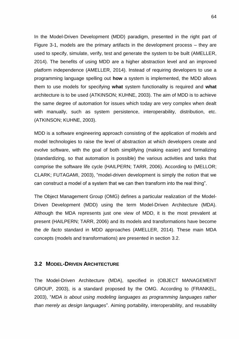
64
In the Model-Driven Development (MDD) paradigm, presented in the right part of
Figure 3-1, models are the primary artifacts in the development process – they are
used to specify, simulate, verify, test and generate the system to be built (AMELLER,
2014). The benefits of using MDD are a higher abstraction level and an improved
platform independence (AMELLER, 2014). Instead of requiring developers to use a
programming language spelling out how a system is implemented, the MDD allows
them to use models for specifying what system functionality is required and what
architecture is to be used (ATKINSON; KUHNE, 2003). The aim of MDD is to achieve
the same degree of automation for issues which today are very complex when dealt
with manually, such as system persistence, interoperability, distribution, etc.
(ATKINSON; KUHNE, 2003).
MDD is a software engineering approach consisting of the application of models and
model technologies to raise the level of abstraction at which developers create and
evolve software, with the goal of both simplifying (making easier) and formalizing
(standardizing, so that automation is possible) the various activities and tasks that
comprise the software life cycle (HAILPERN; TARR, 2006). According to (MELLOR;
CLARK; FUTAGAMI, 2003), “model-driven development is simply the notion that we
can construct a model of a system that we can then transform into the real thing”.
The Object Management Group (OMG) defines a particular realization of the Model-
Driven Development (MDD) using the term Model-Driven Architecture (MDA).
Although the MDA represents just one view of MDD, it is the most prevalent at
present (HAILPERN; TARR, 2006) and its models and transformations have become
the de facto standard in MDD approaches (AMELLER, 2014). These main MDA
concepts (models and transformations) are presented in section 3.2.
3.2 MODEL-DRIVEN ARCHITECTURE
The Model-Driven Architecture (MDA), specified in (OBJECT MANAGEMENT
GROUP, 2003), is a standard proposed by the OMG. According to (FRANKEL,
2003), “MDA is about using modeling languages as programming languages rather
than merely as design languages”. Aiming portability, interoperability, and reusability
65
through architectural separation of concerns, the MDA provides an approach for, and
enables tools to be provided for: specifying a system independently of the platform
that supports it, specifying platforms, choosing a particular platform for the system,
and transforming the system specification into one for a particular platform (OBJECT
MANAGEMENT GROUP, 2003).
According to the MDA specification (OBJECT MANAGEMENT GROUP, 2003), the
MDA promise is to allow the definition of machine-readable application and data
models that allow long-term flexibility of: implementation, integration, maintenance,
testing, and simulation.
With MDA, the designer begins with a high-level model that abstracts from all kinds of
platform issues, and iteratively transforms the model to more concrete models,
introducing more and more platform-specific information (ASSMAN; ZSCHALER;
WAGNER, 2006). A visual representation of the MDA models and transformation,
which are the MDA main concepts, can be seen in Figure 3-2.
Figure 3-2 – The Model Driven Architecture models and transformations
In this section, we present the MDA models (subsection 3.2.1) and the model
transformations (subsection 3.2.2), which is the process of converting one model to
another model of the same system (OBJECT MANAGEMENT GROUP, 2003). The
specific transformation from a Platform Independent Model to a Platform Specific
Model can be seen in Figure 3-2. It is important to mention that most of the text from
Platform Specific Model(PSM)
ComputationalIndependet Model (CIM)
Model Transformation
Trac
eab
ility
bet
wee
n m
od
els
Platform IndependetModel (PIM)

66
this section is extracted and adapted from the MDA Guide version 1.0.1 (OBJECT
MANAGEMENT GROUP, 2003).
3.2.1 MDA Viewpoints and Models: the Separation of Concerns
A viewpoint on a system is a technique for abstraction using a selected set of
architectural concepts and structuring rules in order to focus on particular concerns
within that system (OBJECT MANAGEMENT GROUP, 2003). The Model-Driven
Architecture specifies three viewpoints on a system: a computation independent
viewpoint, a platform independent viewpoint, and a platform specific viewpoint
(OBJECT MANAGEMENT GROUP, 2003) – each one of these are directly related to
a specific type of MDA model.
3.2.1.1 The Computation Independent Model (CIM)
According to (OBJECT MANAGEMENT GROUP, 2003), a Computation Independent
Model (CIM) is a view of a system from the computation independent viewpoint. A
CIM does not show details of the structure of systems – typically, such a model is
independent of how the system is implemented. A CIM is sometimes called a domain
model or a business model. A domain model is the type of model that describes the
environment of a system (ASSMAN; ZSCHALER; WAGNER, 2006). A vocabulary
that is familiar to the practitioners of the domain in question is used in its specification
(OBJECT MANAGEMENT GROUP, 2003).
The CIM plays an important role in bridging the gap between, on the one hand, those
that are experts about the domain and its requirements, and, on the other hand,
those that are experts in the design and construction of the artifacts that together
satisfy the domain requirements (OBJECT MANAGEMENT GROUP, 2003).
A CIM is a model of a system that shows the system in the environment in which it
will operate, and thus helps in presenting exactly what the system is expected to do.
In an MDA specification of a system, the CIM requirements should be traceable to
the Platform Independent Model (PIM) and the Platform-Specific Model (PSM)

67
constructs that implement them, and vice versa (OBJECT MANAGEMENT GROUP,
2003). Making a relation with the traditional software engineering method, this model
can be considered a typical analysis model, since it is expressed in terms of the
problem domain (ASSMAN; ZSCHALER; WAGNER, 2006) – the analysis model has
as critical point the objective to provide a common understanding of the domain
under study (GAŠEVIĆ; KAVIANI; MILANOVIĆ, 2009), just like the CIM. This
common comprehension must then be propagated to the models that refer to the
CIM.
3.2.1.2 The Platform Independent Model (PIM)
A Platform Independent Model (PIM) is a view of a system from the platform
independent viewpoint. A PIM exhibits a specified degree of platform independence
in order to be suitable for the use in a number of different platforms of similar type.
The PIM describes the system, but it does not show details of the system’s use on
the platform (OBJECT MANAGEMENT GROUP, 2003). I.e., the PIM is the high level
abstract design of the system (DURAK; MA MUTYA ICIO LU; O U T N,
2005).
It is important to note, however, that platform independence is a relative term
(FRANKEL, 2003). The MDA Guide defines the platform independence as a quality,
which a model may exhibit – one model might only assume availability of features of
a very general type of platform, while another model might assume the availability of
a particular set of tools (OBJECT MANAGEMENT GROUP, 2003). When asserting
that a language or a model is platform-independent, you must specify the platform
technologies of which it is independent (FRANKEL, 2003).
According to (FRANKEL, 2003), at this level of abstraction, these assumptions are
not severe enough to bind the models to specific implementation technology, but they
do impose constraints on the choice of implementation. A PIM reflects technical
design decisions for a given implementation, and then it can be seen as a Design
Model of the classical software engineering method.

68
3.2.1.3 The Platform Specific Model (PSM)
The separation of the PIM to the Platform-Specific Model (PSM) is a key concept of
the OMG’s MDA (STAHL et al., 2006). A PSM is a view of a system from the platform
specific viewpoint. A PSM combines the specifications in the PIM with the details that
specify how that system uses a particular type of platform (OBJECT MANAGEMENT
GROUP, 2003). According to (STAHL et al., 2006), the PIM abstracts from
technological details, whereas the PSM uses the concepts of a platform to describe a
system. More precisely, a PSM is a computational model that is specific to some
information-formatting technology, programming language, distributed component
middleware, or messaging middleware (FRANKEL, 2003).
A PSM may provide more or less details, depending on its purpose: it will be an
implementation if it provides all the information needed to construct a system and to
put it into operation, or it may act as a PIM that is used for further refinement to a
PSM (OBJECT MANAGEMENT GROUP, 2003). In this last case, platform
information is added to the PIM in successive refinements, which are called model
weaving in (ASSMAN; ZSCHALER; WAGNER, 2006), resulting in a PSM that can be
directly implemented. To be precise, either this model can be executed directly, or it
is used to generate code (ASSMAN; ZSCHALER; WAGNER, 2006). Hence, this
model has a close relation to the implementation stage of the classical software
engineering method.
Figure 3-3 represents, in summary, the different MDA models related to the
separation of concerns available in the standard, where the CIM can be directly
related to an Analysis Model, the PIM can be related to a Design Model, and the
PSM can be related to the Implementation.

69
Figure 3-3 – Separation of concerns via different types of MDA models
3.2.2 MDA Model Transformations
Model transformations – defined as the process of converting one model to another
model of the same system – form a key part of MDA (OBJECT MANAGEMENT
GROUP, 2003). Transformations map models to the respective next level, be it
further models or source code (STAHL et al., 2006). Figure 3-4 illustrates the MDA
pattern, by which a PIM is transformed to a PSM. The represented transformation
can be done manually, with computer assistance, or automatically – transformations
can even use different mixtures of manual and automatic transformations.
Platform Specific Model(PSM)
Platform IndependetModel (PIM)
ComputationalIndependet Model (CIM)
Analysis Model
Design Model
Implementation Model

70
Figure 3-4 – Model transformation. From (OBJECT MANAGEMENT GROUP, 2003)
As stated in the MDA Guide, the drawing presented in Figure 3-4 is intended to be
suggestive and generic (OBJECT MANAGEMENT GROUP, 2003). The empty box in
Figure 3-4 represents all other information that can be combined to the PIM in the
transformation to produce a PSM. The guide states that there are many ways in
which such a transformation may be done. By instance, the guide describes the
following model transformation approaches: marking, metamodel transformation,
model transformation, pattern application, and model merging (OBJECT
MANAGEMENT GROUP, 2003). In addition to the PIM and the platform specific
marks, additional information can be supplied to guide the transformation.
3.3 ONTOLOGY-BASED DEVELOPMENT OF APPLICATIONS
According to (KALIBATIENE; VASILECAS; GUIZZARDI, 2009), in knowledge-based
information systems development, a number of authors (GUARINO, 1998; JARRAR;
DEMEY; MEERSMAN, 2003; WAND; STOREY; WEBER, 1999) suggest to represent
knowledge by means of domain ontologies, since the semantic content expressed by
ontologies can be transformed into information systems artifacts.
According to (ASSMAN; ZSCHALER; WAGNER, 2006), the division of domain
models into platform-aware subject areas (CIM, PIM, and PSM) is a structuring
principle that can be applied to the ontology world. The same authors claim that,

71
because the principle has been invented for the reuse of models in product families
(CIM and PIM are reused in many PIMs and PSMs, respectively), it could enable
reuse of abstract ontologies in ontology families (ASSMAN; ZSCHALER; WAGNER,
2006). The fact that domains are not always disjoint, but often overlap, suggests that
abstract ontologies should be developed that can be shared between domains and
are refined towards concrete ontologies by adding the differences of domains
(ASSMAN; ZSCHALER; WAGNER, 2006).
In order to represent a complex domain, one should rely on engineering tools (e.g.,
design patterns), modeling languages, and methodologies that are based on well-
founded ontological theories in the philosophical sense (e.g., (BUREK et al., 2006)
and (FIELDING et al., 2004)) (GUIZZARDI et al., 2009). A preferable form to create a
domain computational ontology (e.g., an OWL ontology) with improved semantics is
by making use of a rigid ontology engineering like the one presented in (GUIZZARDI,
2007), represented in Figure 3-5, with three basic phases.
Figure 3-5 – The three-phased ontology engineering presented in (GUIZZARDI, 2007)
In a first phase, a conceptual modeling phase (detailed in subsection 3.3.1), highly
expressive languages should be used to create strongly axiomatized ontologies that
approximate as well as possible to the ideal ontology of the domain. The focus of
these languages is on representation adequacy, since the resulting specifications are
intended to be used by humans in tasks such as communication, domain analysis
Computational Ontology
Design Stage
Ontology ReferenceModel
• Domain
comprehension
• Maximum expressivity
• Platform restrictions
• Computational
Restrictions:• Decidability
• Tractability, etc.

72
and problem-solving (GUIZZARDI, 2007). OntoUML is proposed in (GUIZZARDI,
2005) as an ontologically well-founded profile of the Unified Modeling Language
(UML) to be a language used in this step. Making a relation with the MDA context,
(ASSMAN; ZSCHALER; WAGNER, 2006) defends that the domain model of a CIM
can be selected to be a domain ontology. As the CIM intends to represent a domain,
the ontology must be as expressive as possible. Hence, an ontology reference model
is the best option.
Once users have already agreed on a common conceptualization, versions of a
reference ontology can be created as the objective of the Ontology Engineering (its
last phase). These versions have been named in the literature lightweight ontologies.
Contrary to reference ontologies, lightweight ontologies are not focused on
representation adequacy, but are designed with the focus on guaranteeing desirable
computational properties (GUIZZARDI, 2007). The Web Ontology Language (OWL)
is an example of a language suitable for lightweight ontologies. This type of
ontologies is addressed in subsection 3.3.2.
In order to achieve this objective, an intermediate phase is necessary in the Ontology
Engineering: a phase to bridge the gap between the conceptual modeling of
reference ontologies and the coding of these ontologies in terms of specific
lightweight ontology languages. Issues that should be addressed in such a phase
(presented in subsection 3.3.3) are, for instance, determining how to deal with the
difference in the expressivity of the languages that should be used in each of these
phases (GUIZZARDI, 2007).
A clear relation can be made between the MDA models and transformations,
presented in section 3.2, and the different ontology models presented in the rigid
ontology engineering defended by (GUIZZARDI, 2007). This relation is represented
in Figure 3-6. The use of an MDA approach combined with this rigid ontology
engineering may result in a combination of the practical benefits from the MDA
(automation, easy maintenance, etc.) to the semantic benefits from the use of
ontologies.

73
Figure 3-6 – Association between MDA models and different ontology models
In special, the advantages of employing ontology models as analysis models in a
software development method are highlighted in (ASSMAN; ZSCHALER; WAGNER,
2006). They state that, firstly, the use of such models should increase the reliability of
software products since these models are well engineered, often used, and hence
trustworthy, avoiding the risks of a self-made domain analysis. Secondly, ontologies
as analysis models offer a more common vocabulary for the software architect,
customer, and domain expert. This should improve the understanding of the parties
that order and construct software. Then, the standardization of the ontologies
improves the interoperability of applications, because applications that use the
ontology contain a common core of common vocabulary. Finally, they state that
domain and business ontologies can be reused in many software products. In
particular, these types of ontologies may form the core of a software product line,
around which many products are grouped, and from which they reuse domain
terminology. Overall, this improves reuse in the software process (ASSMAN;
ZSCHALER; WAGNER, 2006).
In conclusion, it is important to mention that the relation represented in Figure 3-6
between the MDA models and the ontology artifacts from the different phases of the
ontology engineering defended by (GUIZZARDI, 2007), is not a consensus among
specialists. With that association, we intended to illustrate the use of different types
of ontology artifacts in a MDD context. For more precise definitions in this context, we
recommend (ASSMAN; ZSCHALER; WAGNER, 2006; ATKINSON; KUHNE, 2003;
Computational Ontology
Ontology ReferenceModel
Platform Specific Model(PSM)
Platform IndependetModel (PIM)
ComputationalIndependet Model (CIM)
Design Model

74
GUIZZARDI, 2007) – which, by the way, do not necessarily have a same point of
view about this issue.
In the next three subsections, we are going to present the main characteristics of,
respectively, Ontology Reference Models (subsection 3.3.1), Computational
Ontologies (subsection 3.3.2), and the Ontology Design stage (subsection 3.3.3).
3.3.1 Ontology Reference Models
To create a conceptual ontology model (i.e., an ontology reference model) that
correctly reflects the intended domain and that can be used by different agents
(people, groups of people and machines) to interoperate, a rigid development
method must be used. The ITU-T G.800 Ontology Reference Model uses the
modeling methodology presented in (BARCELOS; GUIZZARDI; GARCIA, 2013),
which is partially based on the Ontological Approach to Domain Engineering
presented in (FALBO; GUIZZARDI; DUARTE, 2002). In this method, shown in Figure
3-7, the steps of the Ontological Approach to Domain Engineering are used with
different level of rigor, abstracting non-essential elements to the modeling context.
Figure 3-7 – Development method of ontology reference models. From (BARCELOS;
GUIZZARDI; GARCIA, 2013)
The scope definition is the first step of the iterative methodology. The ITU-T G.800
Ontology Reference Model has the ITU-T recommendation itself as scope, with a
focus on the defined architectural components.
Scope Definition
Ontology Formalization
Syntatic Validation
Anti-Pattern Treatment
Simulation
Information Acquisition
Conceptualization
Ontology Reference
Model

75
The second step of the methodology is the ontology capture, where the sub activities
of information acquisition and conceptualization are conducted. In order to acquire
information, a domain study is necessary for the modeler to learn about the subject to
be modeled. For the ITU-T G.800 Ontology, besides the recommendation itself, other
ITU-T recommendations were used, as well as specifications of specific multi-layer
technologies. Conceptualizations are immaterial entities that only exist in the mind of
the user or a community of users. In order to be documented, they must be captured
in terms of some concrete artifact. This implies that a language is necessary for
representing them in a concise, complete, and unambiguous way (BARCELOS;
GUIZZARDI; GARCIA, 2013; GUIZZARDI, 2007).
The ontology formalization step consists in the formalization, through diagrams, of
the domain model. In order to represent correctly a domain, an expressive language
must be used. This language should be able to represent information despite of
implementation technologies or limitations.
The ontologically well-founded modeling language used to build the ITU-T G.800
Ontology Reference Model is a version of UML 2.0 first proposed in (GUIZZARDI,
2005) and, thereafter, dubbed OntoUML. OntoUML real-world semantics is defined in
terms of a number of ontological theories, such as theory of parts, of wholes, types
and instantiation, identity, dependencies, unity, etc. OntoUML has been successfully
employed in a number of industrial projects in several different domains
(ALBUQUERQUE; GUIZZARDI, 2013), ranging from Petroleum and Gas
(GUIZZARDI et al., 2009) to News Information Management (CAROLO;
BURLAMAQUI, 2011). In fact, it has been considered as a possible candidate for
contributing to the OMG Semantic Information Model Federation (SIMF)
standardization request for proposal4 after a significant number of successful
applications in real-world engineering settings (BAUMAN, 2009; U.S. DEPARTMENT
OF DEFENSE, 2011). In special, regarding the modeling of multi-layer networks,
OntoUML has already proven to be able to identify ontological deficiencies in the
Recommendation ITU-T G.805, an ITU-T G.800 predecessor, in (BARCELOS et al.,
2011). In addition, recently, in (BARCELOS et al., 2016), OntoUML was used to
4 http://www.omgwiki.org/architecture-ecosystem

76
demonstrate the importance of truly ontological distinctions for standardizations using
the same network recommendation as example.
As graphical languages are not always capable of correctly representing the domain,
Object Constraint Language (OCL) rules were also used in the ITU-T G.800 Ontology
Reference Model for the specification of restriction and derivation rules.
As we intend to create a domain ontology that is a reference model, it is important to
ensure that the final version of the created model allows only instantiation as desired.
That is, the user can only create instances that are possible in the real world. To do
this, the methodology presented in Figure 3-7 has focus on the validation of
information modeled at the diagrams. Two main types of validation are used: (1) the
syntactic one, which guarantees that the OntoUML model created is syntactically
correct, i.e., that the entities created are according to the languages’ metamodel; and
(2) the semantic validation, where the objective is to avoid syntactically correct
diagrams that can be instantiated to generate undesired world of affairs
(BARCELOS; GUIZZARDI; GARCIA, 2013).
The OntoUML Lightweight Editor (OLED) (GUERSON et al., 2015) provides the
syntactical validation. The semantic validation does not ensure that there is no
impossible state of affairs allowed by the ontology. In fact, it does ensure that its
occurrences are reduced. The semantic validation is done in two steps: the first step
is an anti-patterns identification and treatment, and the second step is a simulation
using Alloy (SALES; BARCELOS; GUIZZARDI, 2012).
As stated in (SALES; BARCELOS; GUIZZARDI, 2012), an anti-pattern is a recurrent
decision for a specific scenario that usually results in more negative consequences
than positive ones. The OLED provides a verification tool to check occurrences of
anti-patterns (GUIZZARDI; SALES, 2014; SALES; BARCELOS; GUIZZARDI, 2012).
Simulation can help the modeler to find inconsistencies and unwanted worlds of
affairs allowed by the model. The verification tool can translate the model to Alloy
(JACKSON, 2002). Alloy is a model-checking language that can be used to simulate
possible worlds based on the formalization provided. This kind of validation
guarantees the validity of modeled information in an specific context, thus its usage
significantly improves model quality as the user can make assertions and check if

77
these are valid or not (GUIZZARDI; SALES, 2014; SALES; BARCELOS;
GUIZZARDI, 2012).
3.3.2 Computational Ontologies
In 2001, (BERNERS-LEE; HENDLER; LASSILA, 2001) proposed to handle the
interoperability problem in an open and heterogeneous computing environment, the
Web, by giving more attention to the semantics of terms, thus creating the semantic
web. The autonomic management research community has adopted it as an
important technology in machine-to-machine interaction. Semantic interoperability is
a research vector for autonomic management, since networks and its services
continue to grow in number of components and complexity, as well as the global data
interchange demand. In this context, the usage of knowledge-based systems plays a
key role. In fact, some authors, like (AGOULMINE et al., 2006) believe that “the
knowledge is the most important part of the autonomic-system”.
Knowledge-based systems are built on an architecture with two main components: a
knowledge base, which must be built with a formalization language, and a reasoning
engine – which may be attached to an ontology language or not.
According to (HORROCKS, 2008), semantic web research already had a major
impact on the development and deployment of ontology languages and tools – now
often called semantic web technologies. These technologies have rapidly become a
de facto standard for ontology development, and are seeing increasing use not only
in research labs, but also in large scale IT projects, particularly those where the
schema plays an important role, where information has high value, and where
information may be incomplete (HORROCKS, 2008).
There are diverse knowledge representation paradigms underlying ontology
implementation languages: frames, Description Logics (DL), first (and second) order
logic, semantic networks, etc. This fact makes even more important the correct
selection of the language in which the ontology is to be implemented (GÓMEZ-
PÉREZ; FERNÁNDEZ-LÓPEZ; CORCHO, 2004). During the years, many languages
have been used to represent domain ontologies. Examples include Predicate
78
Calculus, KIF, Ontolingua, UML, EER, LINGO, ORM, CML, DAML+OIL, F-Logic, and
OWL (GUIZZARDI, 2007). After considering some differences between two modeling
paradigms proposed for the semantic web, (PATEL-SCHNEIDER; HORROCKS,
2006) argue that, although some of the characteristics of Datalog languages have
their utility, the open environment of the semantic web is better served by standard
logics.
With the ascension of the semantic web, the standardized representation languages
for this paradigm are frequently employed to build reusable and machine-readable
computational knowledge bases. The World Wide Web Consortium (W3C),
standardization organ for the semantic web, has standardized languages with
different expressivity and that can be used on knowledge bases; the most expressive
one is the OWL, which is going to be presented in subsection 3.3.2.1.
3.3.2.1 OWL: The Web Ontology Language
Although already recognizable as ontology languages (HORROCKS, 2008), the
expressivities of RDF and RDF-S are deliberately very limited: RDF is limited to
binary ground predicates, and RDF-S is limited to a subclass hierarchy and a
property hierarchy, with domain and range definitions of these properties
(ANTONIOU; HARMELEN, 2009). These languages do not, for example, include the
ability to describe cardinality constraints, a feature found in most conceptual
modeling languages, or the ability to describe even a simple conjunction of classes
(HORROCKS, 2008). From this lack of expressivity, the Ontology Web Language,
known by its short name OWL, was born. OWL – currently in its version 2 (HITZLER
et al., 2012) – is the W3C’s current standard for knowledge representation on the
semantic web.
The Assertional Box (ABox) of the OWL ontology is its part that deals with the
individuals and their relationships, while the OWL class structuring is named the
Terminological Box (TBox). According to (HORROCKS, 2008), the term ontology is
often used to refer just to a conceptual schema or TBox, but, in OWL, an ontology
can consist of a mixture of both TBox and ABox axioms. In Description Logics, the
combination of ABox and TBox is known as a knowledge base (HORROCKS, 2008).

79
OWL adopts the Open World Assumption (OWA) (PATEL-SCHNEIDER;
HORROCKS, 2006), in which, when there is no assertion about something, it is
considered as unknown, not as true or false. OWA enables the existence of
incomplete or partial knowledge on knowledge bases. The knowledge
incompleteness can have different results in knowledge-based systems, but it is often
difficult to visualize and correct (i.e., complete). Using the OWA, the OWL axioms
behave like inference rules rather than database constraints. OWL also makes no
Unique Name Assumption (UNA) – i.e., in OWL it is possible to assert (or infer) that
two different names do not refer to the same individual (HORROCKS, 2008).
According to (HORROCKS, 2008), unlike database management systems, ontology
tools typically don not reject updates that result in the ontology becoming wholly or
partly inconsistent, they simply provide a suitable warning.
A key feature of OWL is that its semantics are compatible with the model theoretic
semantics of the SROIQ Description Logic – a decidable fragment of first order logic
with useful computational properties (HORROCKS, 2008; W3C OWL WORKING
GROUP, 2012). SROIQ logics include complex roles, reflexive, antisymmetric, and
irreflexive roles, disjoint roles, a universal role, negated role assertions in Aboxes,
and qualified number restrictions (HORROCKS; KUTZ; SATTLER, 2006).
As well as giving a precise and unambiguous meaning to descriptions of the domain,
the close connection between OWL and the Description Logics allows that the
extensive Description Logics literature and implementation experience can be directly
exploited by OWL tools (W3C OWL WORKING GROUP, 2012). It also allows for the
development of reasoning algorithms that can provide correct answers to arbitrarily
complex queries about the domain. An important aspect of Description Logic
research has been the design of such algorithms and their implementation in (highly
optimized) reasoning systems that can be used by applications to help them
“understand” the knowledge captured in an ontology based on Description Logics
(HORROCKS, 2008). These reasoning mechanisms associated with the OWL
language are presented in subsection 3.3.2.2.

80
3.3.2.2 Reasoning Mechanisms
Building and maintaining ontologies, especially the very large and complex ones, are
very costly and time consuming, and providing tools and services to support this
ontology engineering process is of crucial importance to both the cost and the quality
of the resulting ontology. Therefore, ontology reasoning plays a central role in both
the development of high quality ontologies, and the deployment of ontologies in
applications (HORROCKS, 2008).
In (GAŠEVIĆ; DJURIĆ; DEVEDŽIĆ, 2009), the authors use the Numbernut5
definition of reasoning: “a process of using known facts and/or assumptions in order
to derive a conclusion or make an inference”. It is a complex process involving a
number of abilities, including association, categorization, cause and effect, problem
solving, organization, generalization, and judgment of safety (GAŠEVIĆ; DJURIĆ;
DEVEDŽIĆ, 2009).
Reasoning also refers, more specifically, to the act or process of using one’s reason
to derive one statement or assertion (the conclusion) from a prior group of
statements or assertions (the premises) by means of a given method (GAŠEVIĆ;
DJURIĆ; DEVEDŽIĆ, 2009). To achieve reasoning in semantic web applications,
semantic web researchers and developers must deploy an inference engine that can
derive additional statements that are in their knowledge bases (as well as in the
associated ontologies) but that are not expressed explicitly. The inference engine can
invoke query answering; inference explanation; common set-theory operations of
union, intersection, and difference; predicate logics inferencing; Description Logics
checking for satisfiability, subsumption, consistency, and instance-of relationships;
etc. (GAŠEVIĆ; DJURIĆ; DEVEDŽIĆ, 2009).
In spite of the complexity of reasoning with OWL ontologies, highly optimized
Description Logics reasoning systems such as FaCT++, Racer, and Pellet have
proved to be very effective in practice. In fact, the availability of such reasoning
systems was one of the key motivations for basing OWL on Description Logics
(HORROCKS, 2008). Reasoning is also important when ontologies are deployed in
5 http://www.numbernut.com/glossary/r.shtml

81
applications: it is needed in order to answer standard data retrieval queries as well as
to answer conceptual queries about the structure of the domain (HORROCKS, 2008).
Finally, an important point that must be addressed is that a central issue for
Knowledge Representation formalisms is the tradeoff between expressive power and
reasoning mechanisms (LEVESQUE; BRACHMAN, 1985): the more expressive a
language is, the more complex results to create an inference engine with the
corresponding deductive mechanisms (GÓMEZ-PÉREZ; FERNÁNDEZ-LÓPEZ;
CORCHO, 2004).
3.3.3 Design Stage
Design bridges the conceptual modeling and the implementation. In the Design
Stage, the conceptual specification is transformed in a design specification – a
design model – by taking into consideration a number of issues ranging from
architectural styles, non-functional quality criteria to be maximized, target
implementation environment, etc. (GUIZZARDI, 2007).
A conceptual specification can potentially be used to produce a number of (even
radically) different designs (GUIZZARDI, 2007). In addition, by taking into
consideration a number of implementation issues, from the same design, a number
of different implementations can be produced from a design model (GUIZZARDI;
WAGNER, 2012; GUIZZARDI, 2007). This situation is represented in Figure 3-8.

82
Figure 3-8 – Different computational ontologies considering different design issues
In Figure 3-8, the dotted lines indicate a transformation with human assistance from a
unique conceptual model to different design models. According to (GUIZZARDI;
WAGNER, 2012), it should be clear that a conceptual model, which is a solution-
independent description of a domain, cannot be automatically transformed into a
computational specification without human assistance. The solid lines in Figure 3-8
indicate possible automated transformations from the design models to
computational models.
As can be seen from Figure 3-6, we can make an association from the MDA models
and the ontology artifacts from ontology engineering. In the same way we associate
models, we can also make an association between the MDA transformation between
the PIM to the PSM model and the transformation from a design model to a
computational ontology. Regarding this, the OntoUML and OCL to OWL and SWRL
(OOTOS) transformation had its first version proposed in (BARCELOS et al., 2013).
This transformation provides rigid, formal, and clear design considerations and
contributes to the creation of OWL files with improved semantics to be used for
knowledge representation, communication, interoperation, and reasoning on
computational applications.
Design Model Design Model
Unique OntologyReference Model

83
3.3.3.1 OOTOS: Transformation from OntoUML and OCL to OWL and SWRL
An example of an automated transformation from a conceptual modeling language to
a lightweight ontology language can be found in (BARCELOS et al., 2013). This
transformation aims to bridge the expressivity gap between these languages through
a Model Driven Architecture automated transformation from OntoUML to OWL with
SWRL rules that contributes to (i) make easier the OWL creation from OntoUML, (ii)
eliminate human errors in this process, (iii) improve the resultant OWL ontology
semantics. A newer version of the transformation presented in (BARCELOS et al.,
2013) can be found in the OLED editor (GUERSON et al., 2015). This newer version,
called OntoUML and OCL to OWL and SWRL (OOTOS) transformation, also
implements an OCL to SWRL transformation, improving the semantics of the
resulting computational ontology.
The MDA specification defines model transformation as “the process of converting
one model to another model of the same system” (OBJECT MANAGEMENT
GROUP, 2003). More specifically, the OOTOS transformation can be classified as an
MDA metamodel transformation, which is a model transformation whose specification
is in terms of a mapping between metamodels (OBJECT MANAGEMENT GROUP,
2003). MDA transformations can be done manually, with computer assistance, or
automatically – OOTOS is inserted into the third case, as no human intervention is
necessary during the transformation process.
Figure 3-9 represents the OOTOS transformation inside two different contexts: an
MDA context and the hierarchy of model levels (ATKINSON; KUHNE, 2003).
Figure 3-9 – Transformation's conceptual view
OOTOSOntoUML + OCL
Metamodel
OntoUML + OCL Model
OWL + SWRL Metamodel
OWL + SWRLModel
M2Level
M1Level
instance of
PIM PSM
Transformation

84
Considering the hierarchy of model levels in Figure 3-9, even though the OOTOS
transforms models (which are located in the M1 level – the domain model level), it
can be noted that the OOTOS transformation is specified in terms of the M2 level,
which is the metamodel level. Once models are instances of their metamodels, if
there is a mapping between the concepts of the metamodels (the source and the
target language’s metamodels), any model (i.e., models about any domains) can be
transformed using the same transformation. I.e., transformations in the metamodel
level (M2 level), just like the OOTOS, are reusable across different domains, making
them a more permanent solution. In other words, every time a specific (domain
dependent) transformation between models is performed, this transformation is an
instance of a more generic transformation that was previously defined in the M2 level
and that is generic (domain independent). Note that M2 transformations (language-
dependent) are more reusable than M1 transformations (domain-dependent), which,
by its turn, are more reusable than transformations of user data (sometimes called
the M0 level) (ATKINSON; KUHNE, 2003).
In the MDA context in Figure 3-9, the OntoUML (design) model with OCL rules can
be seen as a PIM, while the OWL with SWRL rules model can be seen as a PSM. A
representation of the OOTOS as an MDA transformation can be seen in Figure 3-10.
In this figure, the part (A) represents the MDA generic transformation pattern just like
specified in (OBJECT MANAGEMENT GROUP, 2003) (the specification figure 3-2).
The part (B) of the figure is the same representation, but now populated with the
OOTOS specific information.

85
Figure 3-10 – OOTOS as an MDA transformation. Adapted from (OBJECT MANAGEMENT
GROUP, 2003)
An intrinsic characteristic of transformations from highly expressive modeling
languages (with focus on knowledge representation) to computational representation
languages (that must be decidable, tractable, etc.) is the loss of expressivity. The
difference of expressiveness results in incompatibilities between some operators of
the languages. I.e., not all constructs and operators from one language can be
transformed to the constructs and operators of the other language. Considering the
whole language constructs and operators, information loss is unavoidable in such
transformation process.
However, information compatibility can be completely guaranteed when dealing with
subsets of the languages, i.e., for some portions of the languages, one can
guarantee no loss of information – a mapping from the languages to be transformed
must, then, be defined and made explicit. Hence, in the OOTOS, a subset of
OntoUML and OCL (the source languages) is mapped to a subset of OWL and
SWRL (the target languages). A rigid design process may allow the user to know
which is the information that is lost between the languages’ transformation, as well as
which parts of its input can be transformed correctly. The user must also be
previously informed which operators are allowed and which are not, and how he or
she can get around this limitation, possibly modifying its input structure.
(A) MDA Transformation Pattern (B) OOTOS Transformation
OntoUMLand OCL
Model (PIM)
OWL and SWRL Model
(PSM)OWL and SWRL
Metamodels
OOTOS’s Specification
OntoUML and OCL Metamodels

86
4 WELL-FOUNDED ONTOLOGY REFERENCE MODEL FOR
TECHNOLOGY-INDEPENDENT MULTI-LAYER
TRANSPORT NETWORKS
As cleverly pointed in (MCGUIRE; BONENFANT, 1998), Niccolò Machiavelli, in his
masterpiece The Prince, observed that “who has not first laid his foundations may be
able with great ability to lay them afterwards, but they will be laid with trouble to the
architect and danger to the building”. To the network architect, standard
specifications lay the foundations for the construction of telecommunications
networks, which are composed of a myriad of technologies (MCGUIRE;
BONENFANT, 1998).
Regarding the importance of standardizations for the telecommunications’
community, this chapter begins with a discussion – adapted from (BARCELOS et al.,
2016) – on the importance of using truly ontological distinctions in standardizations,
in general, and, more specifically, in the ITU-T G.800. In section 4.2, we present
more details about the Recommendation ITU-T G.800, which was modeled to create
the Ontology Reference Model for transport networks. The referred model is
presented in section 4.3.
4.1 TRULY ONTOLOGICAL DISTINCTIONS FOR STANDARDIZATIONS
According to the Oxford Dictionaries6, a standard is “an idea or thing used as a
measure, norm, or model in comparative evaluations”. That is, by means of
comparative evaluations, a standard is something used by human beings to provide
a unique or equal interpretation over something in order to interoperate,
communicate or deal with this thing. Groups of people usually define standards in
order to represent a community consensus. These standards are typically defined in
informal specifications – like the ones in natural language (e.g. English or Chinese) –
6 http://www.oxforddictionaries.com/us/definition/american_english/standard?q=standard

87
or in formal specifications, which are the specifications that use mathematical-based
notation (usually logic-based), in a diagrammatic form or not, to create descriptions in
a more precise way (BARCELOS et al., 2016).
Particularly for the telecommunications’ community, the importance of standards is
notorious (BARCELOS et al., 2016; MCGUIRE; BONENFANT, 1998). The complexity
of the knowledge field is reflected in the large number of standards bodies – e.g.,
ITU-T, IEEE, TM Forum, and Optical Internetworking Forum (OIF), among others. In
this field, a huge number of protocols can only be used when standardized. This vast
number is due to the existence of a central necessity for interoperation between
telecommunications equipment vendors (i.e., equipment must interoperate for an
appropriate communication). Incompatibilities can result in loss of data or absence of
communication and, in both cases, probable serious financial losses (BARCELOS et
al., 2016).
The Recommendation ITU-T G.800 (ITU-T, 2012a) is the standard that provides a set
of constructs (definitions and diagrammatic symbols) and the semantics that can be
used to describe the functional architecture of multi-layer transport networks in a
technology-independent way. The generic functional architecture defined in the
Recommendation ITU-T G.800 provides the basis for a harmonized set of functional
architecture recommendations for specific layer network technologies. This set
includes recommendations that use connection-oriented circuit switching or
connection-oriented packet switching, and connectionless packet switching (e.g. ITU-
T G.803, ITU-T G.872, ITU-T I.326, ITU-T G.8010/Y.1306), and a corresponding set
of recommendations for management, performance analysis, and equipment
specifications (ITU-T, 2012a). In practice, this standard unifies concepts from the
ITU-T Recommendation G.805 (ITU-T, 2000b), for connection-oriented networks, and
from the Recommendation ITU-T G.809 (ITU-T, 2003), for connectionless networks.
Even though the ITU-T Recommendation G.805 is defined using both natural
language and a formal specification in Z, the ITU-T Rec. G.800 is only defined in
natural language. Despite the visible importance of the ITU-T G.800
Recommendation, its text does not contemplate an adequate and precise information
model for the represented domain concepts. According to (GUIZZARDI, 2005), the
suitability of a language to create specifications in a given domain depends on how

88
“close” the structure of the specifications constructed using that language resemble
the structure of the domain abstractions they are supposed to represent. Further,
(GUIZZARDI, 2005) also presents that what is referred by the structure of a language
can be accessed via the description of the specification of the conceptual model
underlying the language, i.e., a description of the worldview embedded in the
language’s modeling primitives. In (MILTON; KAZMIERCZAK, 2008), this is called
the ontological metamodel of the language, or simply, the ontology of the language
(BARCELOS et al., 2016).
Natural languages do not have a well-defined underlying conceptual model, hence,
these languages are notoriously ambiguous (KOOIJ, 1973). This happens because
this category of languages evolved by cognitive and social demand through the
centuries. The usage of natural languages in standardizations may lead to a
document with a series of deficiencies, undermining its comprehension and use in
interoperation, in decision-making, or in problem solutions (BARCELOS et al., 2016).
Figure 4-1 presents the different types of ontological deficiencies that can occur in
standards.
Figure 4-1 – Ontological deficiencies. From (BARCELOS et al., 2011), based on (FETTKE;
LOOS, 2005; GUIZZARDI, 2005)
A recommendation with ontological deficiencies will propagate these problems to all
other recommendations (specifications, standards, norms, etc.) that use it as a basis.
In addition, when used as a reference for conceptual or computational applications,
Construct Overload Construct Excess
Construct Redundancy Incompleteness
Conceptualization Construct Specification Construct

89
this deficient recommendation will possibly generate applications with failures and
interoperation problems (BARCELOS et al., 2016).
Ontological deficiencies can occur when the languages are built over a not-well
specified underlying conceptual model (the language’s metamodel). Apart from
natural languages, formal languages can (and usually do) suffer from such a
problem, even when the language has a formalized underlying conceptual model. It
must be made clear that the existence of ontological deficiencies in a language is not
only related to the presence or absence of a formalization of the language’s
underlying conceptual model: it is a matter of “how well specified” this formalization is
(BARCELOS et al., 2016). A well-specified underlying conceptual model should rely
on a sound well-founded ontology (sometimes called upper ontology), like the Unified
Foundational Ontology (UFO) (GUIZZARDI, 2005), the Bunge-Wand-Weber
Ontology (BWW) (WAND; WEBER, 1993), or the Descriptive Ontology for Linguistic
and Cognitive Engineering (DOLCE) (MASOLO et al., 2003).
According to (GUIZZARDI et al., 2009), the use of foundational concepts that take
truly ontological issues seriously is becoming more and more accepted in the
ontological engineering literature. In addition, the authors state that, in order to
represent a complex domain, one should rely on engineering tools (e.g., design
patterns), modeling languages, and methodologies that are based on well-founded
ontological theories in the philosophical sense (see (BUREK et al., 2006; FIELDING
et al., 2004), for instance). An example of an ontologically well-founded modeling
language is OntoUML, which was the language here used to create the Ontology
Reference Model for the ITU-T G.800.
Especially in complex domains – i.e., domains with complex concepts, relations, and
constraints – and in domains with potentially serious risks of interoperability problems
(the domain specified in the Recommendation ITU-T G.800 fits in both cases), a
supporting ontology engineering approach should be able to:
a. allow the conceptual modelers and domain experts to be explicit, regarding
their ontological commitments, which enables them to expose subtle
distinctions between models to be integrated and to minimize the chances of
running into a False Agreement Problem (GUARINO, 1998);

90
b. support the user in justifying their modeling choices and providing a sound
design rationale for choosing how the elements in the universe of discourse
should be modeled in terms of language elements (GUIZZARDI et al., 2009).
The modeling method here adopted is the one defined in (BARCELOS; GUIZZARDI;
GARCIA, 2013) and presented in subsection 3.3.1.
4.2 THE RECOMMENDATION ITU-T G.800
The primary purpose of a transport network is to transfer user information from a
sender at one location to a receiver at another location (ITU-T, 2010, 2012a). The
objectives of the network architecture (functional model) specification are to support
the description of the generic characteristics of transport networks in a way that is
independent of the technology and of the physical architecture (ITU-T, 2010). The
recommendations ITU-T G.800, ITU-T G.805, and ITU-T G.809 define a common
language and symbols used in the specification of transport and management
functionalities, which are essential for network design and management (ITU-T,
2010). These are international standards defined by the International
Telecommunication Union (ITU) – the United Nations specialized agency for
information and communication technologies7.
Considering a telecommunication network as a complex network that can be
described in a number of different ways depending on the particular purpose of the
description, these recommendations describe the network as a transport network
from the viewpoint of the information transfer capability (ITU-T, 2010, 2012a). These
recommendations describe the functional architecture of transport networks in a
technology-independent way, providing a set of constructs (definitions and
diagrammatic symbols) and the semantics that can be used to describe the
considered viewpoint (ITU-T, 2012a).
The recommendation’s importance is justified by the fact that the architecture there
presented serves as the basis for several other ITU-T recommendations – e.g.
7 http://www.itu.int/

91
G.803, G.872, I.326, G.8010/Y.1306 (ITU-T, 2010). These recommendations
standardize specific technological platforms (e.g., Ethernet and Optical Transport
Network), network management and control (e.g. the Multiprotocol Label Switching
Transport Profile and the Automatically Switched Optical Network), performance
evaluation, and functional specification of equipment (ITU-T, 2000b, 2010). A visual
schema of the importance of the ITU-T G.805 to other technologies is presented in
Figure 4-2.
Figure 4-2 – Technologies defined over the functional architecture of the ITU-T G.805. Adapted
from (ITU-T, 2010)
The importance of the recommendations is highlighted by the many works that intend
to explain and manipulate the concepts there defined – e.g., (BARCELOS et al.,
2011; DIJKSTRA et al., 2007; FORTUNE, 2015) – to provide conceptual basis for the
development of computational applications that solve technology-specific network
problems. Examples of applications based on these three recommendations can be
found in (DIJKSTRA et al., 2008, 2009; VAN DER HAM et al., 2006). The NDL (VAN
DER HAM et al., 2006), previously presented in chapter 2 and used in many network
projects, is strongly based on the functional elements defined by the
recommendations ITU-T G.805 and ITU-T G.800 (XU et al., 2009).
As can be seen in (ITU-T, 2010), the first generic functional architecture
recommendation was the ITU-T G.805, which describes connection-oriented
networks and was used as the basis for ITU-T G.803 (SDH) and ITU-T G.872 (OTN)
architecture recommendations. The next generic functional architecture
recommendation was the ITU-T G.809, which describes connectionless networks and

92
was used as the basis for ITU-T G.8010/Y.1306, the Ethernet functional architecture
(ITU-T, 2010). Finally, the ITU-T G.800 was developed to provide a common
framework to describe both connection-oriented and connectionless networks. The
descriptions in ITU-T G.800 are fully compatible with the descriptions derived from
the earlier recommendations (i.e., the ITU-T G.805 and the ITU-T G.809) although
some of the terminology has been modified (ITU-T, 2010).
4.2.1 Recommendation’s Main Concepts
This functional and structural model proposed in the ITU-T G.800 (and in the
recommendations unified by it, i.e., the ITU-T G.805 and the ITU-T G.809) provides a
high level of abstraction for the basic elements in a network and defines relevant
concepts to simplify network descriptions. Two of its main concepts are partitioning
(some elements can be part of others or be composed of others of the same kind)
and layering (each technology is inside a layer and different aspects of a complex
network can be viewed from different layers). These concepts allow a high degree of
recursion (i.e., reuse of the common specification). Partitioning is important to
describe routing aspects, administrative domain boundaries and the subnetwork (a
recursive definition for a not well-known network, e.g., a cloud network) (BARCELOS
et al., 2016).
Furthermore, the recommendation defines the client/server relationship between
vertically-adjacent layers, which is also a recursive paradigm because any particular
server layer could itself be a client of another server layer (ITU-T, 2010). The
information flow between the two network ends (called source and sink ends) is
performed through adjacent layers up to the real (i.e., physical) transmission at the
lowest layer. These adjacent layers have a client/server relationship where a lower-
level layer (server) provides the transport services to the higher-level layer (client).
For instance, an example of a client/server relationship occurs between the Optical
Channel (OCh) and the Optical Multiplex Section (OMS) layers in Optical Transport
Networks (OTN) – this technology’s layer structure is going to be important for the
provisioning example in chapter 6. It is important to observe that client/server
relationship is not dependent on information flow directionality (uni or bi-directional).

93
It only depends on the network layer organization (technology and protocols)
(BARCELOS et al., 2016).
Besides partitioning, layering, and client/server relationship, other important
definitions are the Transport Processing Functions (TPF) and the Reference Points.
TPFs are blocks that process information that passes through them by their input and
output ports. There are three types of TPFs: Termination Function (TF), Adaptation
Function (AF), and the Layer Processor Function. The TPFs are, together with
Matrices, Subnetworks, Physical Media (PM), and Forwarding Functions (elements
defined in the recommendation), the available Transport Functions. A Reference
Point represents a binding between an input and an output of different instances of
TPFs and other physical components. There are three types of Reference Points:
Access Point, Connection Point, and Termination Connection Point. The elements
that represent the information transfer between Reference Points are the Transport
Entities, which can be Network Connections, Access Transport Entities, Channel
Forwarding Transport Entities, Matrix Connections, or Link Connections.
The ITU-T G.800 contains, in addition to a textual description of the main concepts
and its relationships (in natural language, available in English8), a visual language to
represent the same concepts (BARCELOS et al., 2016). An example of an abstract
transport network using the visual language defined in the ITU-T G.800 is presented
in Figure 4-3.
8 http://www.itu.int/rec/T-REC-G.800-201202-I/

94
Figure 4-3 – Example of the ITU-T G.800 visual notation. From (ITU-T, 2012a)
Despite the relative small number of architectural components defined (directly or
indirectly, inheriting concepts from the ITU-T G.805 and the ITU-T G.809) in the
Recommendation ITU-T G.800, the numerous possibilities of relation between them
makes it a large and complex knowledge domain (BARCELOS et al., 2016;
FORTUNE, 2015) – hence, telecommunications companies are prone to error when
implementing this recommendation.
4.2.2 Recommendation’s Criticisms
As the ITU-T G.805 is the basis for many network standards, due to its fundamental
importance, it is essential for this recommendation to be clear, complete, and
unambiguous, thus eliminating the spread of problems for all its referring documents.
However, despite the visible importance of this recommendation, its document does
not contemplate an adequate and precise information model for the represented
domain concepts. An ontological analysis of this standard, presented in (BARCELOS
et al., 2011), revealed that four different types of ontological deficiencies (for
instance, Construct Overload, Construct Excess, Construct Redundancy, and
Incompleteness) are present in the recommendation. Ambiguities in this standard
were also reported in (DIJKSTRA et al., 2008). More recently, it was shown that the
recommendation’s formal specification is also not precise enough to define the

95
intended domain (BARCELOS et al., 2016). According to (ITU-T, 2010), the
descriptions provided in ITU-T G.800 are fully compatible with the descriptions from
the recommendations ITU-T G.805 and ITU-T G.809, although some of the
terminology has been modified. In fact, the ITU-T G.800 inherits most of the already
identified problems, resulting in formalization with ambiguities, contradictions,
representation gaps, and inconsistencies.
As the recommendation’s text makes clear, since the transport network is a large and
complex network with various components, an appropriate network model with well-
defined functional entities is essential for its design and management (ITU-T, 2012a).
Once the ontological deficiencies are identified, an Ontology Reference Model should
be built to represent correctly the domain, providing a precise definition of
technology-independent multi-layer transport networks. The importance of truly
ontological distinctions (available in Ontology Reference Models built with
ontologically well-founded languages) is discussed in (BARCELOS et al., 2016).
4.3 THE RECOMMENDATION ITU-T G.800 ONTOLOGY REFERENCE MODEL
A first endeavor for the development of an ontology for transport networks based on
the ITU-T G.805 and on the ITU-T G.872 (the recommendation that defines the
architecture of Optical Transport Networks), named Ontology for Optical Transport
Networks (OOTN), was presented in (BARCELOS et al., 2009). However, even
though the OOTN was successfully used for mapping classical concepts of Virtual
Topology Design and Routing and Wavelength Assignment applications, it was built
with a lightweight ontology language (OWL), which, as presented in (GUIZZARDI et
al., 2009), does not have enough expressivity to represent correctly a domain.
Regarding this, an OntoUML Ontology Reference Model was built for the ITU-T
Recommendation G.805. The first version of this ontology was presented in
(MONTEIRO et al., 2010), and the final version was presented in (BARCELOS,
2011). This ontology is in accordance with the three-phased ontology engineering
defended in (GUIZZARDI, 2007). During the development of the ontology, an
ontological evaluation was performed (BARCELOS et al., 2011). This ontological

96
evaluation reported that four different types of ontological deficiencies were identified
in the ITU-T Recommendation G.805.
It is important to mention that, at the development time of the works presented in
(MONTEIRO et al., 2010) and in (BARCELOS et al., 2011), the methodology and the
tools were not available (especially the method to build the reference model
presented in (BARCELOS; GUIZZARDI; GARCIA, 2013) and the validation functions
provided by OLED). The ITU-T G.800 ontology here presented has significant
semantic and correctness improvement over the ITU-T G.805 ontology used in those
works. The latest version of the ITU-T G.800 also has extensions to include Site and
Equipment concepts. The relation between these three parts of the ontology is
presented in Figure 4-4.
Figure 4-4 – The three ontologies of the Ontology Reference Model
The lower level of this ontology is the Recommendation ITU-T G.800 Ontology. This
level contains the most specific elements that compose a transport network. The
second level of abstraction is the Simple Equipment Ontology, which presents
network elements with a higher level of abstraction: equipment and interfaces. The
third level of abstraction is the Simple Site Ontology, used for grouping equipment
over sites. It is important to mention that both the Simple Equipment and Simple Site
ontologies are just a way to raise the abstraction over the ITU-T G.800 elements,
thus, all relations presented in these ontologies are derived from the ITU-T G.800
relations. In the next sections, we are going to present briefly the three ontologies
that are part of the ITU-T G.800 Ontology Reference Model. The ITU-T G.800
Ontology is not going to be fully presented and described because of its great size
Simple Site Ontology
Simple Equipment Ontology
ITU-T Rec. G.800 Ontology
uses
uses

97
and complexity – however, its complete version is available for download in the
thesis shared folder: https://goo.gl/L1UPv4.
4.3.1 The ITU-T G.800 Ontology
The ITU-T G.800 OntoUML ontology has five main packages, according to the
Recommendation definitions: Transport Function, Layer Network, Reference Points,
Transport Entities, and Topological Components. Its scope includes the architectural
characteristics of the recommendation: its elements and their relations (in general,
the architectural components presented in the recommendation’s chapter 6). An
example of a diagram from the Recommendation ITU-T G.800 OntoUML ontology,
representing Termination Functions and its different types, is presented in Figure 4-5.
Figure 4-5 – Example of a diagram from the Rec. ITU-T G.800 OntoUML Ontology
The domain has a strong characteristic that cannot be clearly observed in its textual
description, but that is evidenced by the ontology modeling: the dependency relation
between network architectural components. The ontology model clearly distinguishes
Transport Functions, elements whose bindings are represented by Reference Points,
which, by its turn, are elements that have the information transfer between them
represented by Transport Entities. This element dependence is illustrated in Figure
4-6.

98
Figure 4-6 – Relation between different architectural components
The dependence between the architectural components was identified by the first
complete ontology modeling of the ITU-T G.805, presented in (BARCELOS, 2011) –
this fact also highlights the strong relation between the ITU-T G.800 and the ITU-T
G.805 recommendations. An architectural restructuring proposal for the ITU-T G.805
is also presented in (BARCELOS, 2011).
In order to illustrate the ontology magnitude, the ITU-T G.800 OntoUML ontology has
32 packages, 85 diagrams, 450 classes, and more than 450 OCL rules.
4.3.2 The Simple Equipment Ontology
The Simple Equipment Ontology defines the Equipment concept. The complete
OntoUML ontology is represented in two diagrams, presented in Figure 4-7 and
Figure 4-8.

99
Figure 4-7 – Equipment composition at the Simple Equipment OntoUML Ontology
As can be seen in Figure 4-7, three main classes are created in this ontology:
Equipment, Input Interface, and Output Interface. Equipment is composed of
Transport Functions (except from the Physical Media – restricted by an OCL rule)
and of Input and Output Interfaces. These interfaces are mapped to one input or
output from the Transport Functions that is composing the Equipment (ensured by
other OCL rules).
Figure 4-8 – Equipment interfaces’ bindings and connections

100
As stated in Figure 4-8, equipment interfaces can be related to other network
elements by two distinct relations (derived from relations defined in the ITU-T G.800):
interface binds and interface connects. The interface binds relationship represents
the input and output association that is represented by a Reference Point in the ITU-
T G.800 ontology. The interface connects relationship, by its turn, is mapped to the
relations between the G.800 elements that are represented by connections. In the
lowest layer network, equipment interfaces are connected directly to the Physical
Media inputs and outputs.
4.3.3 The Simple Site Ontology
The Simple Site Ontology is the Ontology Reference Model highest network level of
abstraction: it defines the Site concept. The complete OntoUML ontology is also
represented in a single diagram, presented in Figure 4-9.
Figure 4-9 – The complete Simple Site OntoUML Ontology
According to the ontology, every site is composed of one or more Equipment. Note
that, due to the OntoUML’s weak supplementation restriction (GUIZZARDI, 2005)
over the Site composition by Equipment, its composition was broken in two different
relationships. Sites can only be of type Source and Sink when they have a connects
relationship. This relation is associated with the equipment relations that are inside
the sites. This derivation is provided by OCL rules.

101
5 AN ONTOLOGY-BASED TECHNOLOGY-INDEPENDENT
MULTI-LAYER TRANSPORT NETWORKS PROVISIONING
TOOL
Besides the Ontology Reference Model presented in chapter 4, in this thesis we
intend to also contribute to the provisioning of technology-independent multi-layer
transport networks with a semantically improved computational tool. Hence, using the
ontology-driven development method presented in chapter 3, we have created a
Knowledge-based System (KBS) Provisioning Tool9. As a KBS, the provisioning tool
is composed of three main parts: a knowledge base, a reasoning engine, and the
provisioning logic, just like illustrated in Figure 5-1.
Figure 5-1 – The ontology-based provisioning tool parts
This chapter will present all the components and functionalities of the KBS. For a
better comprehension of the software, we are going to decompose the Provisioning
Tool, just like in Figure 5-2, and present the parts in different sections.
9 Although the provisioning tool and its related conceptual and computational artifacts are a
contribution of this thesis, the software coding was performed by the researcher Freddy Brasileiro
Silva.
Provisioning Logic
Ontology-based ML MT TN Provisioning Tool
Reasoning Engine
AB
ox
TBo
x

102
Figure 5-2 – Decomposition of the provisioning tool
Knowledge-based systems are usually composed of two main parts (STEFIK, 1995):
a knowledge-base and a reasoning engine, just like represented in Figure 5-3.
Figure 5-3 – Provisioning tool decomposition in knowledge base and reasoning engine
The knowledge base of the provisioning tool is going to be presented in section 5.1.
In this section, the knowledge base is divided into its two composing parts (the
Terminological Box and the Assertional Box) and their characteristics are detailed. As
we have already addressed the importance of reasoning engines in subsection 3.3.2,
in this chapter, in section 5.2, we are going to present the HermiT (SHEARER;
MOTIK; HORROCKS, 2008), which is the reasoning engine present in the
provisioning tool. The other important part of the KBS is the implemented
provisioning logic, which is going to be presented in section 5.3.
Limitations of the provisioning tool are presented in chapters 5 and 6 in a distributed
manner, according to the related topic. It must be said, however, that the software
does not present a graphical interface, what can be considered one of the tool most
important limitations. The implementation of a graphical interface that helps the
network operation is left for future work.
Provisioning Logic
Knowledge and Reasoning
Ontology-based ML MT TN Provisioning Tool
Reasoning Engine Knowledge Base
AB
ox
TBo
x
Provisioning Logic
Knowledge and Reasoning Reasoning Engine Knowledge Base

103
5.1 THE KNOWLEDGE BASE
Knowledge bases contain rich information of entities and their relations and are very
useful resources for Artificial Intelligence related applications (WANG; WANG; GUO,
2015). According to (NEELAKANTAN; ROTH; MCCALLUM, 2015), knowledge bases
have been of increasing interest in both industry and academia. As depicted by
(ZHAO et al., 2015), these artifacts are extremely useful for human-like reasoning,
query expansion, coreference resolution, question answering (e.g., Siri, Speaktoit,
iris, SimSimi), information retrieval and other Natural Language Processing tasks like
relation extraction, semantic parsing, etc.
Knowledge bases can be divided into two main parts: (i) a schema, where the
knowledge types are structured, and (ii) the data or information that is present in the
schema, corresponding to instances or individuals (STEFIK, 1995). Considering the
hierarchy of model levels (ATKINSON; KUHNE, 2003), the schema represents the
model level (frequently called M1), while the data or information corresponds to a
lower level, which represents user data (sometimes called M0) (ATKINSON; KUHNE,
2003). In languages based on Description Logics (e.g., OWL), the knowledge base
schema is known as the Terminological Box (TBox), while the user data is known as
the Assertional Box (ABox) (HORROCKS, 2008). The division of the provisioning tool
knowledge base in its two parts is represented in Figure 5-4.
Figure 5-4 – Decomposing the knowledge base in TBox and ABox
Reasoning Engine Knowledge Base
AB
ox
TBo
x

104
The provisioning tool TBox and ABox are going to be described, respectively, in
subsections 5.1.1 and 5.1.2. The separation present in Figure 5-4 is important
because there are substantial differences in the creation and use of the two parts of
the knowledge base. The information presented in this subsection is complemented
with the information present in subsection 5.3.1, which describes the input stage of
the provisioning logic. In this section, the practical use of each one of the knowledge
base parts is detailed. The red line dividing the TBox and the ABox in two parts,
represented in Figure 5-4, indicates a performance technique that consists in using
two different models, as it is going to be presented in subsection 5.1.1.2.
5.1.1 The Terminological Box
In order to be used in a KBS, a knowledge base must be implemented in some kind
of computational artifact. Hence, the TBox of the provisioning tool is implemented as
an OWL file. The tool TBox is the ITU-T G.800 OWL Computational Ontology, which
is the result of the ontology-driven development method described in section 3.3, as
represented in Figure 5-5.
Figure 5-5 – Different ontology models used and their relation
OWL G.800 ProvisioningComputational Ontology
OntoUML ITU-T G.800Ontology Reference Model
Trac
eab
ility
bet
wee
n m
od
els
OOTOSModel TransformationOntoUML G.800
ProvisioningDesign Model
TerminologicalBox

105
The provisioning tool TBox is indirectly based on the ITU-T G.800 Ontology
Reference Model, which has been used as the basis for the development of an ITU-T
G.800 Provisioning OntoUML design model with SWRL rules (the existing traceability
of the models from the different levels is also represented in Figure 5-5). Following
the ontology-based development method here adopted, the design model was
transformed, with the use of the OOTOS transformation (presented in subsection
3.3.3.1), resulting in the OWL ITU-T G.800 Provisioning Computational Ontology,
which is the TBox itself.
In the next subsection (5.1.1.1) we are going to present (almost completely) the ITU-
T G.800 OntoUML Provisioning Design Model. The OWL Computational Ontology
that is the provisioning tool TBox is presented in subsection 5.1.1.2.
5.1.1.1 The ITU-T G.800 OntoUML Design Model for Provisioning of Transport
Networks
The OntoUML Design Model developed for the provisioning domain is a simple
model with five diagrams and a total of 48 classes and 19 SWRL rules. Considering
the number of classes and rules in the Ontology Reference Model, from which it is
based, the design model can be considered a huge simplification of the reference
model. The development of the design model was oriented by the requirements and
definitions of the provisioning tool.
OntoUML Diagrams
Although some authors, e.g., (ASSMAN; ZSCHALER; WAGNER, 2006), argue that
the design model is not an ontology, we have used OntoUML, an ontology language,
for the formalization of the design model for provisioning of transport networks. This
decision was taken because of two main factors: (i) OntoUML is an expressive
language, which results in better-formalized models; and (ii) its usage allows us to
transform the design model to the OWL Computational Ontology via the OOTOS
transformation.

106
The design model first diagram, presented in Figure 5-6, specifies the hierarchy of
transport functions that are made available in the provisioning tool. Within the
software, the user can manage Matrices, Adaptation Functions, and Termination
Functions. The complexity of Transport Function types is here reduced to simplify the
software operation by the user. It can be noted that some transport functions that are
formalized in the ITU-T G.800 OntoUML Ontology Reference Model are not available
in the design model, such as the Layer Processor Function. This reduction, however,
configures a limitation of the provisioning tool with relation to the domain (i.e., the tool
operates just over a portion of the domain).
A special case occurs with the Matrix concept, which was modified to increase the
usability of the software through a design decision. In the design model, as can be
seen in Figure 5-6, the Matrix is presented in two possibilities, Source and Sink.
However, the design model concepts of Source and Sink Matrices refer to the same
Matrix concept in the Ontology Reference Model, i.e., there is a controlled case of
construct redundancy.
Figure 5-6 – Taxonomy of transport function
The diagram presented in Figure 5-7 specifies the main relationships used in the
network provisioning tool. It presents the Equipment composition (named hasPart) by
Transport Functions and by Input and Output Interfaces, as well as the mappings
(relation maps) from these interfaces to the transport function inputs and outputs. In

107
addition, the relations int_binds, tf_binds, and eq_binds are also formalized. These
relations, which are derived relations between concepts of the same class (i.e., they
are self-associations (GOMAA, 2011)), have an important use in the provisioning tool
algorithm. As derived relations, they have associated derivation rules, which are the
rules 8 to 10, in Table I-1, from the Appendix I – SWRL Rules.
Figure 5-7 – Main relations of the design model
Another important relation defined in the diagram presented in Figure 5-7 is the path.
This relation indicates that an interface is being used in a specific path. This relation
differs from the int_binds relation as the path relation indicates a logical relation,
representing an information transfer, while the int_binds relation indicates a physical
relation between interfaces. For a path to exist, first the interfaces must be bound
(with the relation int_binds).
The int_binds relation relates interfaces from different equipment, while the path
relation relates interfaces from the same equipment and interfaces from different
equipment, just like represented in Figure 5-8. In this figure, interfaces are
represented as white arrows and equipment are represented as squares.

108
Figure 5-8 – Different use of the relations int_binds and path
The int_binds and the path relations are directly associated with, respectively, the
circuit provisioning and the connection provisioning capabilities of the software. This
association is better described in section 5.3.
Figure 5-9 presents all the specific compositions of the Transport Functions (defined
in the diagram presented in Figure 5-6) by Port (Inputs and Outputs).
Figure 5-9 – Inputs and outputs in the design model
INT_
SOU
RC
E
INT_
SIN
K
path path path path path
int_binds int_binds

109
Figure 5-10 presents half of the diagram that formalizes all possible bindings
between input and output ports. Differently from the Ontology Reference Model, in
this diagram, the relations that formalize the bindings are not material relations, but
formal relations. This happens because we are not interested in manipulating the
Reference Points that are used as relators in the Ontology Reference Model.
Figure 5-10 – Fragment of the allowed bindings between inputs and outputs
For a better visualization, instead of representing the entire diagram, the complete list
of allowed bindings is represented in Table 5-1.
Table 5-1 – Allowed bindings according to the design model
From To Comment
Adaptation Function Sink Input Termination Function Sink Output Adaptation Functions can only
bind Termination Functions Adaptation Function Source Output Termination Function Source Input
Adaptation Function Sink Output Adaptation Function Source Input This is the unique case of Sink to
Source binding
Matrix Sink Input Adaptation Function Sink Output Matrices can only bind
Adaptation Functions Matrix Source Output Adaptation Function Source Input
Termination Function Sink Input PM Output There are three different binding
possibilities from a Termination
Function Sink Input
Termination Function Sink Input Matrix Sink Output
Termination Function Sink Input Adaptation Function Sink Output

110
Termination Function Source Output PM Input There are three different binding
possibilities from a Termination
Function Source Output
Termination Function Source Output Matrix Source Input
Termination Function Source Output Adaptation Function Source Input
Finally, the diagram presented in Figure 5-11 represents the Layer Network concept
and its relations with the transport functions and with other Layer Networks. As can
be seen, a Layer Network is defined by some Termination Functions, has a relation
with Matrices (Matrices hasLayer a specific Layer Network), and Adaptations adapts
from and to some Layer Network. In addition, a Layer Network instance is a client of
other Layer Network instance.
Figure 5-11 – Layer network relationships
All the relations here presented have associated integrity and derivation rules, which
are presented in Table I-1, from the Appendix I – SWRL Rules.
SWRL Rules
Despite the natural choice of OCL for the formalization of the integrity and inference
rules of the design model, we chose to formalize these rules directly in Semantic
Web Rule Language (SWRL). This decision was taken because of the small size of
the model and because of the simplicity and small number (only 19) of the rules.
Consequently, the rules formalized for the design model are going to be the same
rules used in the OWL Computational Ontology, which are the rules directly present
in the provisioning tool. All the nineteen rules associated with these two artifacts are
presented in the Appendix I – SWRL Rules.

111
5.1.1.2 The ITU-T G.800 OWL Ontology for Transport Network Provisioning
With the design model specified in OntoUML, the OOTOS transformation is used to
generate the OWL Computational Ontology. This OWL ontology is used as the
provisioning tool knowledge base. However, intending a better performance of the
provisioning tool, the OWL Computational Ontology here developed is not a single
OWL file, instead, it is composed of two different OWL ontologies: the Consistency
Model and the Inference Model, just like presented in Figure 5-12.
Figure 5-12 – OWL ontology models in the knowledge base
Performance is a well-known problem in the semantic web community, where there is
a tradeoff between the expressivity of the knowledge representation artifact (i.e., the
ontology) and the scalability of the systems used to process them (HORROCKS,
2008). Reasoning in the classical paradigm (the class of languages which OWL is
part) is difficult for any reasonably expressive ontology language (PATEL-
SCHNEIDER; HORROCKS, 2006). Performance issues are outside the scope of this
thesis. However, to situate better the reader, a brief discussion about the provisioning
tool performance is presented in section 6.4.
Although high performance is not a requirement of the provisioning tool, the tool
development tried to reach acceptable execution times. The technique here
presented makes use of two different OWL files in order to contribute to better
reasoning times in the provisioning tool. While the Consistency Model is a heavy
(highly axiomatized) ontology, the Inference Model is a lighter ontology – thus
allowing a faster reasoning. Instead of using the reasoning in the Consistency Model,
Inference Model Consistency Model
TBox
ABox
TBox
ABox
Knowledge Base

112
we just use the validate and the isValid functions made available by JENA, an open
source Java framework for building semantic web and linked data applications
(CARROLL et al., 2004). As it is going to be presented, the SWRL rules are only
attached to the Inference Model, not to the Consistency Model.
The use of the two OWL ontologies as a unique knowledge base is almost
transparent to the user. Regarding this separation, the unique action that the user
must take is to provide two inputs containing the models, as it is going to be
presented in the description of the provisioning tool logic (section 5.3).
Differently from what is presented in Figure 5-5, not just one, but two different
transformations from the design model to OWL ontologies are necessary to create
the knowledge base. The Consistency Model and the Inference Model used in the
provisioning tool can be found in the thesis shared folder (https://goo.gl/L1UPv4).
The Consistency Model
The generation of the Consistency Model uses the OOTOS transformation with its
default settings, just as it is implemented in OLED. In this transformation, just the
OntoUML to OWL part of the OOTOS transformation is used – i.e., there is no
transformation from OCL to SWRL. The use of the OOTOS transformation
guarantees a consistent resulting OWL file (when the OntoUML model used as input
is well built, as in this case). The resulting OWL ontology, i.e., the Consistency
Model, is graphically presented in Figure 5-13.
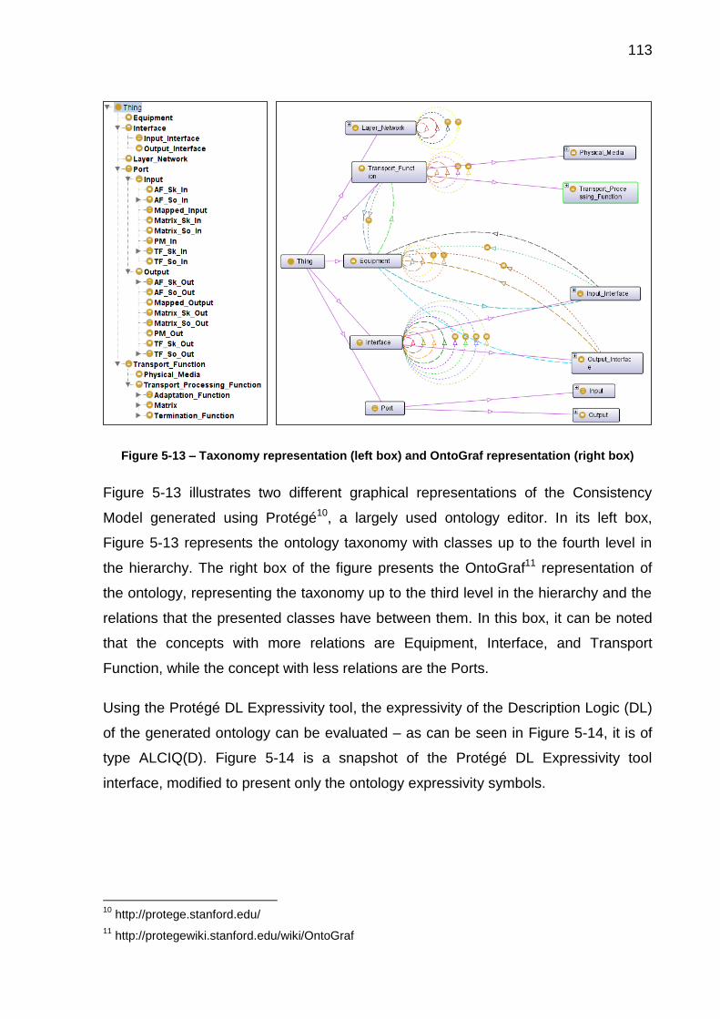
113
Figure 5-13 – Taxonomy representation (left box) and OntoGraf representation (right box)
Figure 5-13 illustrates two different graphical representations of the Consistency
Model generated using Protégé10, a largely used ontology editor. In its left box,
Figure 5-13 represents the ontology taxonomy with classes up to the fourth level in
the hierarchy. The right box of the figure presents the OntoGraf11 representation of
the ontology, representing the taxonomy up to the third level in the hierarchy and the
relations that the presented classes have between them. In this box, it can be noted
that the concepts with more relations are Equipment, Interface, and Transport
Function, while the concept with less relations are the Ports.
Using the Protégé DL Expressivity tool, the expressivity of the Description Logic (DL)
of the generated ontology can be evaluated – as can be seen in Figure 5-14, it is of
type ALCIQ(D). Figure 5-14 is a snapshot of the Protégé DL Expressivity tool
interface, modified to present only the ontology expressivity symbols.
10
http://protege.stanford.edu/
11 http://protegewiki.stanford.edu/wiki/OntoGraf

114
Figure 5-14 – Consistency Model DL expressivity
The metrics of the Consistency Model can be visualized using the Protégé Ontology
Metrics tool. An adapted snapshot of this tool can be seen in Figure 5-15.
Figure 5-15 – Consistency Model metrics
We can see from Figure 5-15 that, according to the Ontology Metrics tool, the
Description Logic of the Consistency Model is of type ALCRIQ(D). This result differs
from the one presented in the DL Expressivity tool, as it presents the R extension.
The R extension means the existence of limited complex role inclusion axioms,
reflexivity and irreflexivity, or role disjointness. As these axioms really occur in the
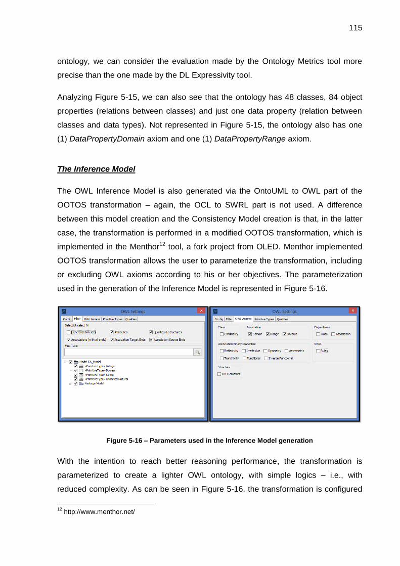
115
ontology, we can consider the evaluation made by the Ontology Metrics tool more
precise than the one made by the DL Expressivity tool.
Analyzing Figure 5-15, we can also see that the ontology has 48 classes, 84 object
properties (relations between classes) and just one data property (relation between
classes and data types). Not represented in Figure 5-15, the ontology also has one
(1) DataPropertyDomain axiom and one (1) DataPropertyRange axiom.
The Inference Model
The OWL Inference Model is also generated via the OntoUML to OWL part of the
OOTOS transformation – again, the OCL to SWRL part is not used. A difference
between this model creation and the Consistency Model creation is that, in the latter
case, the transformation is performed in a modified OOTOS transformation, which is
implemented in the Menthor12 tool, a fork project from OLED. Menthor implemented
OOTOS transformation allows the user to parameterize the transformation, including
or excluding OWL axioms according to his or her objectives. The parameterization
used in the generation of the Inference Model is represented in Figure 5-16.
Figure 5-16 – Parameters used in the Inference Model generation
With the intention to reach better reasoning performance, the transformation is
parameterized to create a lighter OWL ontology, with simple logics – i.e., with
reduced complexity. As can be seen in Figure 5-16, the transformation is configured
12
http://www.menthor.net/

116
to remove cardinality transformation, disjointness, and association binary properties.
The Generalization sets and “UFO structure” options are also kept unchecked. The
result of the transformation is then manually combined with the same SWRL rules of
the design model (fully presented in the Appendix I – SWRL Rules) to create the
complete Inference Model.
An intrinsic characteristic of transformations from more expressive models to less
expressive models is the loss of expressivity. This loss of expressivity occurs in the
transformation from the design model to the Inference Model and, as this model is
less axiomatized than the Consistency Model, it allows more unintended states.
However, this situation does not configure a problem because the Inference Model is
just used to perform inferences through SWRL rules. The consistency of the model is
only verified in the Consistency Model, not in the Inference Model. The reduction of
complexity of OWL can be observed in Figure 5-17, which pictures the Description
Logic of the Inference Model as being the ALHI(D).
Figure 5-17 – Inference Model DL expressivity
The reduced number of axioms in the Inference Model can be clearly noted in Figure
5-18. When comparing the information from Figure 5-18 (Inference Model metrics)
with the one from Figure 5-15 (Consistency Model metrics), we can observe that the
number of classes, object properties, and data properties of the model are the same.
However, it can also be observed that the number of axioms has decreased 35,92%

117
(from 710 to 455), and that the number of logical axioms has decreased 44,19%
(from 577 to 322). Considering the class axioms, the number of SubClassOf axioms
is also the same, but the count of all other axioms has been reduced to zero, just like
the number of the DisjointObjectProperty axioms (which are Object Property axioms).
Figure 5-18 – Inference Model metrics
Not depicted in Figure 5-18, this ontology also has one (1) DataPropertyDomain
axiom and one (1) DataPropertyRange axiom.
In order to illustrate briefly how the Inference Model can simplify reasoning, we have
performed a simple test with the Hermit reasoner (version 1.3.8) inside the Protégé
editing tool. This test aimed to verify the reasoning time for non-populated models
(i.e., just their TBoxes). The reasoning was performed five times, the maximum and
the minimum values found in tests 1 to 5 were eliminated, and the final value consists
in the average of the three remaining values. The results of the test, presented in
Table 5-2, indicate that the Inference Model takes 5,37% of the Consistency Model
reasoning time.

118
Table 5-2 – Reasoning comparison for consistency and Inference Models
Test Number Consistency Model
Reasoning Time (ms) Inference Model
Reasoning Time (ms)
1 1056 63
2 972 47
3 1200 78
4 1035 62
5 1114 47
Average (ms) 1068,33 57,33
It is important to emphasize that this test was performed just to provide minor
evidences that the lower complexity of the Inference Model allows it to have a better
reasoning time than the Consistency Model. However, this test cannot be considered
sufficient, as the reasoning functions applied to each one of the models are different,
also because, when populated, there is an increase in the complexity of the models.
5.1.2 The Assertional Box
In Figure 5-12, the knowledge base of the provisioning tool is composed of two
different OWL files, both with their respective TBoxes and ABoxes – transparently
implemented to the user. Even though the two models do not contain the same
information in their TBoxes, they must have the same information in their ABoxes at
all moments (represented by the orange double arrow in Figure 5-12). I.e., the
ABoxes must be kept synchronized and work as a single ABox during software
execution. These two ABoxes must be populated with the same instances and
relations between instances every time an operation is performed in the ABox (e.g.,
just like a distributed database works), as the existence of different information may
lead to inconsistencies. Considering this, hereafter the ABoxes are going to be
treated as a single one.
Once the TBoxes (both the Consistency Model and the Inference Model) are
available, the ABox must be populated to create the software knowledge base. I.e.,
the network elements must be provided as instances to be treated by the
provisioning tool. The population of the knowledge base is performed by inputting a
network specification (an abstraction of a real network). This specification is written in

119
a defined format, which is defined in accordance with the OWL knowledge base –
and thus, build upon the concepts of the Recommendation ITU-T G.800. The
specification format is presented in the Appendix II – Input TXT Files Structure. The
population process is represented in Figure 5-19.
Figure 5-19 – Network specification
In Figure 5-19, a group of people abstracts the reality (i.e., a real network) according
to the concepts of the Recommendation ITU-T G.800 to build a specification, which is
going to be used to create the provisioning tool ABox. In the figure, a group of people
is building a specification according to a common conceptualization, what reduces
the possibility of semantic problems. However, a single person (e.g. a network
operator) could perform this stage alone, if necessary. The network is formalized in a
structured document, in this case, a text file.
One of the requirements of the provisioning tool is that it must operate according to
different equipment states. Regarding this, the ABox is going to be populated with
two different information: the network elements that are already installed or
operational, which are going to be called declared equipment; and the elements
that are not installed or operational, but that are available to be used in the network.
This latter type of equipment is going to be called here possible equipment. For the
provisioning tool, the declared equipment must be provided as input (i.e., it is
mandatory), while the user can provide possible equipment or not (i.e., it is optional).
Figure 5-20 represents this situation. More information about the input of the
provisioning tool can be found in subsection 5.3.1, which deals with the input
according to the software algorithm.
Reality Conceptualization Formalization
Abstracted in Formalized in
***Equipment:
x,;
Input_Interface: x1,x2;
Output_Interface:y1,y2;
Terminati....

120
Figure 5-20 – ABox constitution
Once the inputs are defined in a structured text file (.txt), they pass through a
transformation to OWL instances, which will form the ABox. The instances generated
from the transformation of the input files are loaded into the computer memory using
the JENA Ontology Application Programming Interface (API). In memory, together
with the previous loaded TBox, the knowledge base of the provisioning tool is
completed. This situation is represented in Figure 5-21.
Figure 5-21 – Knowledge base formation
A question that may occur is: why use a text file for the network formalization instead
of directly writing it in OWL? OWL has a markup syntax that resembles the
HyperText Markup Language (HTML) one, which makes difficult the writing directly
on it. Some ontology editors aim to reduce this problem with a user-friendly graphical
interface – like the highly used Protégé. However, even with the use of these editors,
ABox
DeclaredEquipment
PossibleEquipment(optional)
Inputs
***
Equipment: x,;
Input_Interface: x1,x2;
Output_Interface:y1,y2;Termination_Function:
a1,b2;
Adaptation_Function: z;
AB
ox
TBo
x
.OWL
transformation
Knowledge Base in memory
AB
ox
TBo
x

121
it is still difficult to insert all information when dealing with a large number of
individuals – which is, in most cases, the situation of the networks declarations. The
writing of the information in a simple structured text file may facilitate this process.
The structured text file has its syntax completely presented in Appendix II – Input
TXT Files Structure. The provisioning tool expects correct input files to execute the
provisioning. No syntax or semantic treatments of the inputs are performed by the
provisioning tool: inconsistency checking is left to the reasoner after the
transformation to OWL. A better treatment of the input files is considered a future
work.
5.2 HERMIT: THE PROVISIONING TOOL REASONING ENGINE
According to (DENTLER et al., 2011), a reasoner is a program that infers logical
consequences from a set of explicitly asserted facts or axioms and typically provides
automated support for reasoning tasks such as classification, debugging and
querying. The reasoning engine performs a central function in the transport network
provisioning tool: it is responsible for performing the inferences (and the consistency
checking) in the Inference Model. To accomplish this objective, the chosen reasoner
must be able to support ABox and SWRL reasoning, to support Java (the
provisioning tool implementation language), as well as it must have a fast algorithm.
Regarding this, the HermiT13 (SHEARER; MOTIK; HORROCKS, 2008) reasoning
engine version 1.3.8 was used in the implementation of the provisioning tool.
HermiT is a sound and complete OWL reasoner that implements a fast reasoning
algorithm, the hypertableau calculus (DENTLER et al., 2011). According to
(ABBURU, 2012; DENTLER et al., 2011), besides its fast reasoning algorithm,
HermiT presents other important features. Some of them are: (i) reasoning support
for TBox, ABox, and SWRL rules; (ii) its support for OWL API (it uses OWL API 3.4.3,
which is backwards compatible with OWL APIs 3.3.x, 3.2.x and 3.1.x); (iii) its open
13
http://hermit-reasoner.com/

122
license, GNU Lesser General Public License (GLGPL); and (iv) its compatibility with
Java 1.5 or higher (ABBURU, 2012; DENTLER et al., 2011).
According to (SHEARER; MOTIK; HORROCKS, 2008), HermiT uses an improved
blocking strategy and an optimization that tries to reuse existing individuals rather
than generating new ones. HermiT also incorporates a number of other
optimizations, such as a more efficient approach for handling nominal (concepts that
refer to a particular individual in the ABox), and various techniques for optimizing
ontology classification. The developer’s tests show that HermiT is usually much faster
than other reasoners when classifying complex ontologies, and that it is already able
to classify a number of ontologies which no other reasoner has been able to handle
(SHEARER; MOTIK; HORROCKS, 2008). The good performance is verified in other
reasoners evaluations, like (KANG; LI; KRISHNASWAMY, 2012) and (DENTLER et
al., 2011) – the latter performs a comparison of reasoners for a specific scenario
(OWL 2 EL profile).
Regarding the Consistency Model, for performance purposes, instead of using the
reasoner in this model, we just use JENA validate and isValid functions. These
functions use JENA built-in reasoner to detect when constraints are violated by some
data set14. As just consistency-related functions are performed (i.e., inferences are
not verified), a better performance is expected when using these functions.
5.3 THE PROVISIONING TOOL LOGIC
The ontology-based KBS provisioning tool implementation logic is composed of three
main phases, as represented in Figure 5-22: (i) the Input Stage, (ii) the Setup Stage,
and (iii) the Provisioning Stage. The third stage can be divided in Manual
Provisioning and Automatic Provisioning. In Figure 5-22, the wheels in the top right
corner of the boxes represent the moments when the reasoning engine is executed.
14
https://jena.apache.org/documentation/inference/

123
Figure 5-22 – Stages of the provisioning tool logic
In the next subsections, we are going to present the provisioning tool logic divided in
the three stages represented in Figure 5-22. To present the software logic, we are
going to use a simplified flowchart with just four shapes: terminal, process, decision,
and an adapted cloud to indicate links between different parts of the represented
flowchart. For the process shape, we use the blue color to represent user interaction,
the gray color to represent internal processes, and the purple color to represent
reasoning. Our intention here is to use a high level of abstraction in the graphical
representation and then make detailed textual explanations of each flowchart step.
The complete provisioning tool flowchart can be observed in Figure 5-23.
Stage 1:INPUT
Stage 2:SETUP
Stage 3A:MANUAL
PROVISIONING
Stage 3B:AUTOMATIC
PROVISIONING

124
Figure 5-23 – Complete provisioning tool flowchart
For a better visualization and comprehension, we are going to divide and present the
flowchart in three pieces, corresponding to the stages presented in Figure 5-22, in
subsections 5.3.1 to 5.3.3.
Enter Consistency
Model
Enter Declared
Equipment
Enter Possible
EquipmentTreat Inputs
Generate ABox
Are there at least two declared
equipment?
Are the interfaces correct?
yes
no no
Is there an eq. composed of
PM?yes yes
no
Enter Inference
Model
no
Any inconsistency
found?yes
Check Consistency
Perform Inferences
Inform User Save OWL
Select INT_SOURCE
Select INT_SINK
Set Mode(Automatic or Manual)
Mode
Set Restrictions
Set Priority Find Paths
Select Path for
Provisioning
Paths were found?
yes
no
Bind Path
Automatic
Manual
Check Consistency
Perform Inferences
Any inconsistency
found?
Select VAR_OUT
VAR_OUT = INT_SINK?
yes
no
Are there VAR_IN
candidates?
Are there VAR_OUT
candidates?
yes
yes
no
no
Select VAR_IN
Binds VAR_OUT
with VAR_IN
yes
Provision another
path?
no
yes
Inform User
Save OWL
no
Set Path Relation

125
5.3.1 Input Stage
The first stage of the provisioning tool is the Input Stage, represented in Figure 5-24.
In this stage, the load and the population of the provisioning tool knowledge base
occurs, as well as some initial verifications.
Figure 5-24 – Provisioning tool Input Stage
The flowchart process and decision shapes, presented in Figure 5-24, are going to
be detailed in the next paragraphs.
Enter Consistency Model and Enter Inference Model: The two first processes are
the input of the two parts of the provisioning tool TBox by the user. As presented in
section 5.1, the TBox consists of two different OWL ontologies, one for the execution
of inferences (the Inference Model) and the other one for consistency checking (the
Consistency Model). The manual input of the TBox parts in the provisioning tool was
chosen because this would let the provisioning tool more flexible for modifications or
updates. For example, depending on which modification is made, a newer version of
the ontology models can be generated without affecting the provisioning tool logic. It
should be highlighted that the correct development of a new knowledge base should
always be done according to the ontology-based development method here adopted.
Enter Consistency Model
Enter Declared Equipment
Enter Possible Equipment
Treat Inputs Generate ABox
Are there at least two declared equipment?
Are the interfaces correct?
yes
Proceed to final procedure
no
Proceed to final procedure
no
Is there an eq. composed of PM?
yes yes
Proceed to final procedure
no
Run Reasoner
Enter Inference Model

126
Enter Declared Equipment and Enter Possible Equipment: These two steps
consist in the population of the inserted TBox with the network data. In these steps,
the individuals and their relations will be provided by the user and will form (later, in
the Generate ABox process) the provisioning tool ABox, as represented in Figure
5-20.
The inputs that form the ABox are two structured TXT files: the declared equipment
and the possible equipment. The former has a structured declaration of the elements
(equipment, their components, and the relationships between them) that are already
operational in a network and that are going to be provisioned. The declared
equipment is an obligatory input for the software operation, but the possible
equipment declaration is optional. After being input, these text files are then
translated to OWL instances (i.e., an ABox). The ABox and the input TBox form the
provisioning tool knowledge base.
Treat Inputs: In the Treat Inputs process, the TXT files are verified for syntactical
problems. Other small treatments are also performed, for example: instances with
different names (case sensitively) are set as disjoint from each other; and repeated
layers must be ignored.
Generate ABox: Once the inputs are treated, they are transformed to the OWL
ABox, which is going to be used in the provisioning tool. Just like presented in
subsection 5.1.2, the provisioning tool ABox is, in fact, two separate ABoxes that are
kept updated in a transparent way to the user. At the end of this process, the
knowledge base is complete (with the TBox and the ABox).
After the Generate ABox process, the Input Stage continues with three verifications.
These verifications evaluate if any mistake in the inputs prevents the software
execution. Such verification is necessary to reduce the processing time when there is
a problem and to warn the user to correct the problem. In all these verifications, when
a problem is identified, the final procedure is called – what is represented in the
flowchart in Figure 5-24 as a red cloud. If no problems are identified, the software
execution continues.
The final procedure, presented in Figure 5-25, can indicate a correct or an incorrect
completion of the software execution. Besides the Input Stage, the final procedure

127
can also be invoked in the last stage of the software, the Provisioning Stage. Within
this procedure, the Inform User process prints an informative text to the user to
indicate the execution result – i.e., the correct end is reported or, in case of failures or
errors, a description of the problem (and of what have caused it) is reported. An
example of error that invokes the final procedure is an inconsistency detection by the
reasoner. In both cases, i.e., representing a correct or problematic execution, the
OWL knowledge base is saved and made available to the user in the Save OWL
process. In the case of an error, after the end of the software execution, the user can
analyze the informed text and the OWL knowledge base made available to verify the
cause of the problems.
Figure 5-25 – Provisioning tool final procedure
Back to the Input Stage, the first of the three verifications is “Are there at least two
declared equipment?”, which verifies if at least two equipment are declared (i.e., if
the declared equipment TXT file contains at least two equipment declarations). As
the provisioning is performed from an input interface of an equipment to the output
interface of other equipment, there must be at least two equipment so the
provisioning can happen.
The second verification, “Are the interfaces correct?”, is about the correctness of the
interfaces that were specified in the declared equipment input. Four verifications are
performed in this verification to guarantee the minimum conditions for the
provisioning to happen:
1. Is there at least one equipment that contains an output interface that maps an
output port of a source component?
2. Is there at least one equipment that contains an input interface that maps an
input port of a source component?
3. Is there at least one equipment that contains an output interface that maps an
output port of a sink component?
Inform User Save OWLFrom last stage

128
4. Is there at least one equipment that contains an input interface that maps an
input port of a sink component?
The four verifications above do not ensure that the declared equipment specification
is free of errors – it only intends to reduce the probability of problems.
The third and final verification of this step is the “Is there an equipment composed of
PM?”, which verifies if there is at least one equipment that contains a physical
medium (PM) in the declared equipment or in the possible equipment declarations.
I.e., there must be at least one PM, which can be of types declared or possible.
Equipment with physical medium are required as they are the only way to transport
the information from the source part of the network to the sink part of the network.
Run Reasoner: After the three verifications, as can be seen in Figure 5-24, the
software execution proceeds to the Run Reasoner process. This process is an
abstraction of other processes and decisions, which composes the reasoning
procedure presented in Figure 5-26. As can be noted, the complete flowchart,
presented in Figure 5-23, does not present the Run Reasoner process, but its
composing parts. Besides the Input Stage, the reasoning procedure is also called at
the end of the third stage of the provisioning tool execution.
Figure 5-26 – Reasoning procedure
The reasoning procedure is composed of two processes and one verification. In the
first process, the HermiT reasoner is used to perform inferences. The inferences are
performed according to the nineteen rules presented in Appendix I – SWRL Rules.
The indirect relations int_binds, eq_binds, tf_binds, and path are especially important
for the provisioning tool, as these relationships are directly queried in the next stages.
no
Proceed to next stage
Proceed to final procedure
Any inconsistency found?
yesCheck
ConsistencyPerform
Inferences

129
In the second process, the consistency of the model is evaluated using the validate
and the isValid functions available in the JENA framework. If the reasoner founds any
inconsistency, then the final procedure is invoked. If no problem is found, the
software execution proceeds to its next stage, which is the Setup Stage.
5.3.2 Setup Stage
Figure 5-27 represents the processes in the second stage of the provisioning tool
execution, the Setup Stage. This is a simple stage composed of only three
processes: Select INT_Source, Select INT_Sink, and Set Mode (Automatic or
Manual).
Figure 5-27 – Provisioning tool Setup Stage
Select INT_SOURCE: INT_SOURCE is the input interface to be provisioned. The
user must choose the INT_SOURCE from a list of candidate interfaces – i.e., input
interfaces that are mapped to input ports of source components.
Select INT_SINK: INT_SINK is the output interface to be provisioned. The user must
choose the INT_SINK from a list of candidate interfaces – i.e., output interfaces that
are mapped to output ports of sink components.
Set Mode (Automatic or Manual): The user must now choose between the two
available provisioning modes: automatic or manual. The Provisioning Stage has
different flows according to the option selected in this process. The manual and the
automatic modes are going to be described, respectively, in subsections 5.3.3.1 and
5.3.3.2.
Select INT_SOURCE
Select INT_SINK
Set Mode(Automatic or
Manual)Proceed to next stage
From last stage

130
5.3.3 Provisioning Stage
The Provisioning Stage is the third and last stage of the tool execution. The
connection provisioning and the circuit provisioning of the network happens in this
stage, which can be considered the most important one.
This stage implements two distinct executions, which depend on the provisioning
mode (automatic or manual) selected in the Set Mode process (from the Setup
Stage). This section describes the logics of these two different modes: the Manual
Provisioning, presented in subsection 5.3.3.1, and the Automatic Provisioning,
presented in subsection 5.3.3.2.
At the end of this stage (independently of the choice for the automatic or manual
modes), the reasoning procedure is invoked to verify inferences and the consistency
of the knowledge base, which was modified during the provisioning processes. If
inconsistencies are found, the final procedure is invoked. If no inconsistencies are
found, the user may choose if he or she wants to provision another path or finish the
software execution (i.e., finish the network provisioning).
5.3.3.1 Manual Provisioning
The manual provisioning mode’s flowchart is represented in Figure 5-28.
Figure 5-28 – Manual provisioning flowchart
Select VAR_OUTVAR_OUT = INT_SINK?
Run Reasoner
yes
no
From last stage
Are there VAR_IN candidates?
Are there VAR_OUT
candidates?yes
yesProceed to
final procedure
Proceed to final procedure
no
noSelect VAR_INBinds VAR_OUT
with VAR_IN
Set Path Relation

131
The manual provisioning is iteratively performed based on two variables: VAR_OUT
and VAR_IN, which represents the interfaces (an output and an input interface,
respectively) selected by the user in the path to be provisioned. Using Figure 5-29,
we are going to exemplify the manual provisioning and the use of these variables and
of its associated relations.
Figure 5-29 – Use of variables in the manual provisioning
Figure 5-29 represents four steps of the manual provisioning of a simple network with
just two equipment. The represented steps are the VAR_OUT selection, the VAR_IN
selection, the binds VAR_OUT with VAR_IN (int_binds assignment), and the set path
relation (path assignment). In Figure 5-29, equipment are represented as blue boxes
and equipment interfaces are represented as arrows. INT_SOURCE and INT_SINK
are the desired interfaces to be provisioned. The information about which interfaces
are INT_SOURCE and INT_SINK was provided by the user in the Input Stage.
Select VAR_OUT: The selection of a VAR_OUT interface is the first step of the
manual provisioning. The VAR_OUT corresponds to an output interface of an
equipment that is going to be in the provisioned path. The VAR_OUT is chosen from
a list of pre-selected candidates, evaluated by the decision “Are there VAR_OUT
candidates?” in the flowchart. If no VAR_OUT candidate is found, then there is a
problem in the provisioning (i.e., the network cannot be provisioned through the
currently selected path). Considering the first iteration in the manual provisioning,
where no VAR_IN have already been chosen by the user, the absence of VAR_OUT
candidates probably indicates a bad network description. Considering later iterations,
the absence of VAR_OUT candidates indicates that the user has chosen to provision
a path through interfaces that do not allow new connections or there are no
INT_
SOU
RC
E
INT_
SIN
K
VAR_OUT candidates
INT_
SOU
RC
E
INT_
SIN
KVAR_IN candidates
INT_
SOU
RC
E
INT_
SIN
K
VAR_OUT candidates
INT_
SOU
RC
E
INT_
SIN
K
STEP 1: VAR_OUT selection
STEP 2: VAR_IN selection
STEP 3: int_binds assignment and VAR_OUT selection
STEP 4: path assignment

132
interfaces that are internally connected with the selected VAR_IN (or INT_SOURCE,
depending on the iteration). If no candidates are available, the final procedure is
invoked. In this procedure (presented in Figure 5-25), the software indicates the
problem to the user and is terminated.
The selection of VAR_OUT candidate interfaces considers three points:
1. Type of interface: it must be an output interface;
2. Availability: the VAR_OUT candidates must not be bound to other interfaces;
3. Physical relation: the transport function that contains the ports that are
mapped to the candidate interfaces must have a tf_binds relation with the
transport function that contains the port that is mapped to the INT_SOURCE (if
VAR_IN is not set yet – e.g., in the first step of Figure 5-29, i.e., the first
iteration) or to the VAR_IN (in any other case). In brief, a series of bound ports
must exist to allow the information flow.
An example of the selection of VAR_OUT candidates is illustrated in Figure 5-30.
Figure 5-30 – Example of VAR_OUT candidates’ selection
In Figure 5-30, the interfaces in the black circles are not candidates, as they do not
comply with the third restriction rule presented in the list (regarding physical
relations). The bound interfaces (represented in purple) are not candidates, as they
do not comply with the second rule. As can be seen in Figure 5-30, only the available
interfaces (represented as blue arrows) that have a physical relation to
INT_SOURCE or VAR_IN are listed as VAR_OUT candidates (inside the red circles).
INT_SOURCE or VAR_IN
VAR_OUT candidates
NOT VAR_OUT candidates
Available interface
Pair of bound interfaces
Legend

133
This transitive relation is necessary to allow the information flow from INT_SOURCE
or VAR_IN to VAR_OUT.
Special restrictions must be established for matrices, which are the transport
functions that implement network protection (inside subnetworks, e.g. in
recommendations ITU-T G.873.1 and ITU-T G.798). If the protection rules were not
implemented, a user could perform (de)multiplexing in a matrix, what is not allowed
by the transport network recommendations. These implemented restrictions are:
1. The interface that maps the output of a source matrix can only have one path
relation. The same restriction applies to the interface that maps the input port
of a sink matrix. This restriction is represented in Figure 5-31.
Figure 5-31 – Matrix protection special case
2. The second restriction is that the information source and destination must be
the same for the protection case. When an input interface that maps the input
port of a source matrix is evaluated as an VAR_IN candidate, it must be
observed if it has already been used in a previous provisioning execution (if it
is already provisioned – i.e., if it contains a path relation). If the interface is
already provisioned, to allow a new provisioning, the current INT_SOURCE
and the current INT_SINK must already have a path relation with this interface
(guaranteeing that the information source and destination are the same, and
that it is a case of network protection). The same verification must be
Information must have the same source and destination
Allowed information transfer: protection
Not allowed information transfer: (de)multiplexing
Sou
rce
Mat
rix
Sin
kM
atri
x
Sou
rce
Mat
rix
Sin
kM
atri
x

134
observed when choosing the output interface that maps an output port of a
sink matrix as VAR_OUT.
However, these rules are only verified by the provisioning tool when an interface
directly maps a matrix port. If the input or output ports of the matrix are not directly
mapped by an interface, then just part of the restriction is going to be verified or, in
the case that there is no direct mapping, no restriction is going to be verified. This
lack of verification is a limitation of the provisioning tool with relation to the domain. It
was a design decision in order to simplify the implementation, allowing better
performance of the software. Improvements in this sense are left for future work.
Continuing with the software logic, the user must choose a VAR_OUT from the list of
candidates. All the interfaces selected as VAR_OUT during the provisioning process
are kept in a data structure for the later path relation attribution (see Set Path
Relation process). Once a VAR_OUT is selected, a first verification should be made:
“VAR_OUT = INT_SINK?”. If the answer is positive, then the provision of the
networks is over, as the desired output interface was already reached by a path. If
this happens, the Set Path Relation process is executed.
If the result is negative, then the objective of the provision was not reached yet, and
the path (i.e., the circuit provisioning and connection provisioning) must continue to
be built. This is done by selecting an input interface, which is represented as
VAR_IN. This situation can be observed in the second step of Figure 5-29, which
represents a situation where VAR_OUT not equals INT_SINK and, hence, a VAR_IN
must be selected.
Select VAR_IN: The VAR_IN corresponds to an input interface that is going to be in
the provisioned path. However, before the selection of the VAR_IN, another question
must be answered: Are there VAR_IN candidates? A negative answer to this
decision box, represented in Figure 5-28, indicates that something went wrong with
the provisioning process: the user was trying to create a path in an unsupported way.
Once this happens, the final procedure is called, the user is informed of the problem,
and the provisioning algorithm is finished. As future work, the algorithm could be
made more robust and, instead of finishing the provisioning algorithm, it could make
a rollback to the last state when there were available paths (i.e., it could be back to

135
the last valid provisioning option, when there was at least one VAR_IN or VAR_OUT
available). Another possibility could be the following: the software could check one
step further to see if the displayed interfaces have other possible bindings or not.
The VAR_IN candidates’ selection is performed considering the following restrictions:
1. Type of interface: it must be an input interface;
2. Availability: the VAR_IN candidates must not be bound to other interfaces;
3. Layer hierarchy: the VAR_IN candidate must be part of:
a. a matrix that is in the same layer that has the transport function that
contains the port that is mapped to VAR_OUT; or
b. a transport function (except matrices) that is in a layer that has a client-
server relation with the layer that has the transport function that
contains the port that is mapped to VAR_OUT;
4. Allowed bindings: the interfaces must map the transport functions’ ports that
can be bound together. There are 11 cases of allowed relations, which are
presented in Table 5-1;
5. No loop: the VAR_IN must not be the INT_SOURCE.
Besides the five listed restrictions, the restrictions considering the protection
performed by matrices (presented in the VAR_OUT selection process) must also be
observed. An example of VAR_IN candidates’ selection is presented in Figure 5-32.
Figure 5-32 – Example of VAR_IN candidates’ selection
VAR_IN candidates
VAR_OUT
NOT VAR_IN candidates
Available interface
Pair of bound interfaces
LAYER 2(client of 1)
LAYER 1(server of 2)(client of 0)
LAYER 0(server of 1)
1
2
Legend

136
In Figure 5-32, we can see that the interfaces inside the black circle indicated by the
number one are not candidates, as they do not comply with the allowed bindings rule
(rule number 4). The interface in the black circle indicated by the number two is not a
candidate because it does not comply with the layer hierarchy rule (rule number 3).
All interfaces inside the green circles are VAR_IN candidate interfaces.
Just like happens with the interfaces selected as VAR_OUT, the interfaces selected
as VAR_IN during the provisioning tool execution are also kept in a data structure for
the future path relation assignment (at the Set Path Relation process).
Binds VAR_OUT with VAR_IN: Once a VAR_OUT and a VAR_IN are selected,
these interfaces must be physically related in order to allow the information transfer.
The relation that represents this physical relation between interfaces is the int_binds
relation. When considering the whole path, we name the process of performing the
physical connection from the source interface to the destination interface a circuit
provisioning. The circuit provisioning is directly related to the int_binds relation.
The provisioning tool, instead of directly assigns the int_binds relation between the
interfaces, assigns the binds relation between the ports that are mapped to the
interfaces to be bound. Later, with the reasoning of the model, an SWRL rule (to be
more specific, the rule number 08 of the table presented in Appendix I – SWRL
Rules) guarantees the int_binds relation between the interfaces. The third step in
Figure 5-29 represents the assertion of this relation once a VAR_IN is selected.
When the binding is performed, the software continues the provisioning with a new
VAR_OUT selection.
Set Path Relation: The final process of both the manual provisioning and the
automatic provisioning is the assignment of the path relation between the interfaces
that are in the path that were provisioned.
Once all interfaces (INT_SOURCE, and all VAR_INs and VAR_OUTs that were
selected during the provisioning process) in the path are known (i.e., they are stored
in the already mentioned data structure) and physically connected through the
int_binds relation, the information transfer should be represented by the path relation.

137
This process is here named connection provisioning. The path relation assignment is
represented in the fourth step of Figure 5-29.
The path relation connects all interfaces in a path, representing the logical
connection between them – i.e., the path relation represents the information transfer
from the source interface to the destination interface, through all intermediate
interfaces between these two.
5.3.3.2 Automatic Provisioning
The second available provisioning mode is the automatic mode, which has the
processes represented in Figure 5-33.
Figure 5-33 – Automatic provisioning flowchart
This provisioning mode discovers all possible paths from INT_SOURCE to INT_SINK
according to some user-defined criteria (restrictions and priority). The user must
select one of the paths found to provision the network. The main steps of this
provisioning mode are represented in Figure 5-34.
Set Restrictions Set Priority Find Paths
Select Path for Provisioning
Run Reasoner
From last stage
Paths were found?
yes
Proceed to final procedure
no
Bind Path Set Path Relation

138
Figure 5-34 – Simple example of the automatic provisioning steps
All processes of this provisioning mode are going to be described in this section.
When possible, Figure 5-34 is going to be used as an example for the processes.
Set Restrictions: Differently from the manual provisioning, where a single path is
established with the user’s direct supervision, the automatic provisioning verifies all
possible paths between INT_SOURCE and INT_SINK. This discovery of paths is
performed using the same verifications and variables (VAR_IN and VAR_OUT) of the
manual provisioning. However, depending on the size of the network to be
provisioned, a huge number of paths can be found between two points. Considering
this, the user can optionally set restrictions to limit the number of paths to be found.
The definition of the restrictions has two objectives:
a) to simplify the user’s selection of a path: the restrictions are going to make the
Find Paths process to return only the paths desired by the network operator.
With a restricted list, (i) paths that are not desired cannot be selected by the
user, eliminating human errors in the network provisioning, and (ii) and the
user’s task to select the best provisioning option is largely simplified, saving
time; and
b) to improve the software performance: the restrictions are verified every time
an interface that can be part of the path is discovered in the Find Paths
process. If in one of these verifications the path that is being discovered does
not fit the restrictions, the software closes the non-compliant path discovery
execution thread, saving processing time and reducing the time spent to return
to the user the possible paths.
Four different restrictions may be applied by the user. These restrictions are:
INT_
SOU
RC
E
INT_
SIN
K
INT_
SOU
RC
E
INT_
SIN
K
INT_
SOU
RC
E
INT_
SIN
K
INT_
SOU
RC
E
INT_
SIN
K
STEP 1: Find paths (according to restrictions and to priority)
STEP 2: Select a path
STEP 3: int_binds assignment (representing physical conn.)
STEP 4: path assignment (logical connection – inf. transfer)

139
1. the maximum number of paths to be found;
2. the maximum number of interfaces in a path (size of the path);
3. the maximum number of new bindings in a path; and
4. the maximum number of interfaces of possible equipment in a path (when the
possible equipment definition is available).
The first restriction (maximum number of paths) sets an upper limit to the number of
paths that are going to be found in the Find Paths process and exhibited to the user.
As an example, in Figure 5-34, the number of all the possible paths in that network is
3 – setting this restriction on that network would reduce this number to 1 or 2 paths,
according to the user’s definition.
The maximum size of the path (i.e., maximum number of interfaces) restriction
guarantees that all paths that are going to be exhibited to the user have an allowed
size according to the operator’s definition. I.e., no paths with a number of interfaces
greater than the limit are going to be exhibited. In the provisioning tool, the size of a
path is counted by the total number of (input or output) interfaces in it (including
INT_SOURCE and INT_SINK, and interfaces from declared or possible equipment).
Using Figure 5-34 as an example, the size of all paths there represented is 4.
The maximum number of new bindings restriction sets a limit to the number of new
physical connections that are accepted during the provisioning of the network. The
new bindings, represented by the int_binds relation, are new physical connections
between equipment. Once again, using the network presented in Figure 5-34, it is
required at least one physical connection to perform the provisioning between
INT_SOURCE and INT_SINK. This required physical connection is represented in
the third step of this figure.
The fourth and last restriction, which is the maximum number of interfaces of possible
equipment in a path, restricts the number of possible equipment that can be used in a
network with the intention to prioritize the equipment of that network that are already
operational (i.e., the declared equipment). The lower number of interfaces of this type
of equipment means that a smaller number of possible equipment is used in the
network, ensuring savings. However, this restriction is only available to the user if an

140
input file with possible equipment were previously provided (in an optional process in
the Input Stage – presented in the subsection 5.3.1).
The effect of the use of each one of these restrictions during the automatic discovery
of the paths is going to be better explained in the Find Paths process.
Set Priority: Once the restrictions over the maximum number of paths are defined,
the automatically discovered paths must be allocated in this defined number to be
returned to the user. This allocation must be based on a criterion defined by the user,
which is defined in this process. To define a criterion, the user must prioritize a path
characteristic. Three priority options are given to the user:
1. the number of interfaces in the path (size of the path);
2. the number of new bindings in the path; and
3. the number of interfaces of possible equipment in the path (when the possible
equipment definition is available).
Every time a new path is found in the Find Paths process and accomplishes all
restrictions defined in the Set Restrictions process, it is allocated in a vector in
increasing order according to the priority here established. The size of the vector was
previously defined by the user in the maximum number of paths restriction. If the
vector is already full and a new path found has a smaller value of the priority criterion
than the path in the last position of the vector, then the path that occupies the last
position is replaced by the new path in the vector, which is reordered according to the
priority criterion. By the end of this process, the paths are exhibited to the user
ordered by the priority criterion.
To conclude this process, it must be said that the third option (number of interfaces of
possible equipment) is exhibited to the user only when a possible equipment
specification was previously provided by the user. Both this process and the previous
process happen before the first stage of the example provided in Figure 5-34.
Find Paths: In this process, which can be considered the most important process of
the automatic provisioning, all possible paths that fit in the restrictions provided by
the user are found and exhibited. The provisioning tool path finding – according to
the restrictions and to the priority set – is represented by the step 1 of Figure 5-34.

141
The automatic path finding uses the same processes and variables presented in the
manual provisioning mode. I.e., the same iterative process that consists of the
selection of VAR_OUT and VAR_IN variables are performed. However, instead of
building a single and final path, this process uses a multiway tree structure to
discover all possible paths. By the end of the path finding, all possible paths identified
are allocated in a vector sized accordingly to the value of the restriction maximum
number of paths. To better illustrate the path finding process, consider the simple
example network presented in Figure 5-35.
Figure 5-35 – Example of network to be automatically provisioned
The left part of Figure 5-35 represents an abstraction of the network presented in the
right part of the same figure. The network is composed of three defined equipment
(D1, D2, and D3) and a single possible equipment (P1). In the example, the interface
1 is the INT_SOURCE and the interface 18 is the INT_SINK – i.e., a path must be
established from the interface 1 to the interface 18. In this network, the interface 11
from D2 is already physically bound with the interface 15 from D3 (represented by
the int_binds red arrow in the right part of Figure 5-35).
The abstraction of the network, in the left part of Figure 5-35, shows all the network’s
interfaces, representing them as candidates to be in a path or not. The candidates
are represented in green, while the interfaces that are not candidates are
represented in red. By candidates, we mean all interfaces that may form a path. In
this case, the green interfaces are all VAR_IN candidates, all VAR_OUT candidates,
and interfaces 11 and 15, which are not VAR_IN or VAR_OUT candidates (as they
INT_SOURCE
INT_SINK
Output Interfaces
Input Interfaces
Output Interfaces
Input Interfaces
4 52
86
12
16 17
D1
D3
1
2 3 4 5
14 15 16 17
18
P1D2
10 11 12 13
6 7 8 97
1110
1
3
9
13
14 15
18

142
are already bound) but that may be in a path. For the candidates, the equipment
internal interfaces’ relations (in orange) and the physical bindings between different
equipment interfaces (in black) are represented. The dashed line in interfaces 8, 9,
12, and 13 indicates that these interfaces are from possible equipment.
Figure 5-36 represents the multiway tree structure used to discover all possible paths
when automatically provisioning the example presented in Figure 5-35. As can be
seen in the top of the figure, no restrictions (represented by the number -1) were set
for this example. In this example, the provisioning tool returns three paths to the user,
called Path X, Path Y, and Path Z in Figure 5-36.
Figure 5-36 – Example of unrestricted automatic path provisioning
The paths that can be provisioned, which is the partial result of the provisioning
process, are then displayed to the user, which may choose one among all
possibilities. Besides the tree structure, Figure 5-36 also presents a table with all the
attributes of each path (the attributes are related to the restrictions that the user can
set). Note that, although all paths found in this example have exactly the same size
(6 interfaces), this does not happen in all cases.
Regarding the different restriction that the user may apply, we have already
presented how the maximum number of paths restriction acts on the path finding
1 3
7
9
Path X: 1, 3, 7, 10, 14, 18
Path Y: 1, 3, 7, 11, 15, 18
10
11
13
14
15
14
18
18
18 Path Z: 1, 3, 9, 13, 14, 18
Path Path Size New Bindings # Possible Int.
X 6 2 0
Y 6 1 0
Z 6 2 2
Path relation
Path relation and new int_binds
Legend
Path relation and old int_binds
t1 t2 t3 t4 t5 t6
Restrictions: max_path = -1, max_size = -1, max_bind = -1, max_pos_int = -1

143
(defining the size of the vector that allocates the found paths). However, how do the
other restrictions act in the path finding process? Every time that a new node (an
interface) is included in the tree, the paths’ attributes are verified: the number of
interfaces, the number of new bindings, and the number of interfaces of possible
equipment. If, during the verification of the restrictions, it is confirmed that the path is
not a possible solution – i.e., the path does not fit into the restrictions – then the
continuation of that branch of the tree is interrupted (saving memory use, processing
time, and improving performance). Only the paths that accomplish the restrictions are
allocated in the final vector of possible paths that are going to be presented to the
user. An example of this verification is presented in Figure 5-37, which presents the
results of the path finding for the same network presented in Figure 5-35. Differently
from Figure 5-36, which is based on the same network and does not have
restrictions, in the example of Figure 5-37, the restriction of maximum number of new
bindings is set to 1 (max_bind = 1) and the restriction of maximum number of
interfaces of possible equipment is set to 0 (max_pos_int = 0).
Figure 5-37 – Example of restricted automatic path provisioning
It can be observed, in Figure 5-37, that two of the three paths that could be formed
when no restrictions are applied were aborted during the construction of the tree
structure. The first interrupted path corresponds to the Path Z of Figure 5-36. This
path is interrupted because it is verified that it contains one possible interface, while
the restriction defines that it should have none. The second interrupted path, which
corresponds to the Path X of Figure 5-36, is interrupted because it is verified that it
1 3
7
9
Path Y
10
11
14
15 18
t1 t2 t3 t4 t5 t6
Restrictions: max_path = -1, max_size = -1, max_bind = 1, max_pos_int = 0
max_pos_int > 0
max_bind > 1

144
has two int_binds relations, i.e., two new bindings, what violates the defined
restriction for a maximum of one new binding. In the example of Figure 5-37, the only
path that is in accordance with the defined criteria is the Path Y.
Moreover, it should be explained how the priority criterion influences the path finding
process. In two cases, the defined priority acts just in the ordination of the vector of
paths that is going to be shown to the user. The first one is the case where there is
no restriction about the maximum number of paths, and the second case is when the
number of possible paths found is smaller than the number set in the restriction.
However, when the number of possible paths is greater than the defined restriction,
the priority criterion has a more important role in the path finding process. In this
situation, the priority defines which paths are going to be returned to the user and
which paths are not going to be returned. As the vector has a limited number of
paths, some paths that were already allocated in the vector can lose their places to a
recently found path that have a smaller value of the defined priority. Figure 5-38
presents an example, for a same set of possible paths, of how different restrictions
and priorities present different results to the user.
Figure 5-38 – Examples of restrictions’ and priority’s influence over automatic path finding
Figure 5-38 have two main parts: the left part, which presents the paths found, and
the right part, which presents the vector of possible paths being mounted while the
paths are being found.
In the left part of Figure 5-38, there are six different paths from INT_SOURCE
(represented as a green circle) to INT_SINK (red circle). These paths are discovered
in the exact sequence presented in the figure (P1, P2, …, P6). The blue circles
E2: (4, 2, 2)
P3
P3 P6
E3: (6, 2, 0)
P1
P1
P3 P1
P3 P1 P4
P3 P5 P1
P3 P5 P1
E1: (6, 2, 2)
P1
P1
P3 P1
P3 P1 P2
P3 P1 P2
P3 P6 P1
P2
P2
P1: (6, 1, 0)
P2: (6, 2, 2)
P3: (4, 0, 0)
P4: (6, 2, 0)
P5: (6, 0, 0)
P6: (4, 2 0)
tim
e
Paths Found

145
represent declared interfaces and the purple circles represent interfaces from
possible equipment. Black lines represent already existing bindings (abstracting the
fact that they are internal or external from the equipment) and red lines represent
new bindings. The values of triples in the right part of the paths indicate, respectively,
the size of the path (i.e., its total number of interfaces), the number of new bindings,
and the number of interfaces from possible equipment.
In the right part of Figure 5-38, there are three executions of the provisioning tool. All
presented executions have the same restriction on the vector’s size of a maximum of
3 paths. This restriction is indicated by the vector’s three boxes. The executions,
however, have different restrictions on the maximum number of interfaces, new
bindings, and interfaces of possible equipment. These three restrictions are
respectively indicated as values of a triple represented in the right side of the
execution name (above the column of vectors). Inside the triple, the number indicated
in red represents the priority criterion chosen. The final vector with the result of the
path finding process is highlighted in yellow in Figure 5-38.
The first execution (E1) does not impose any practical restriction to the paths that are
found, because its defined restrictions are higher than the paths’ attributes. P1 and
P2, both with size 6, when found, are allocated in the vector. When P3 is found, it is
inserted in the vector in the first position, as it has size 4 and the prioritized attribute
is the path size (number of interfaces). With all positions of the vector occupied, as
P4 and P5 have the same size of the path of the last position of the vector (size 6),
they are not allocated in the vector. Finally, as P6 have size 4, it is allocated in the
second position of the vector (as the first position also has size 4) and, by doing this,
it moves P1 to the third position and eliminates P2 as an answer to be shown to the
user.
The E2 execution imposes a size restriction of 4 interfaces in its paths. Regarding
this, in this execution, every time that a path with a higher number of interfaces is
identified, the path finding of the rest of this path is not performed. Therefore,
differently from what is represented in Figure 5-38 (which shows complete paths), the
paths P1, P2, P4, and P5 are aborted by the provisioning tool before their INT_SINKs
are reached. In E2, just paths P3 and P6 are presented to the user, as these are the
only paths with size smaller than or equal to 4.

146
Finally, in E3, the last execution, the main restriction is the number of interfaces from
possible equipment, and the priority is set to the number of new bindings. The
defined restriction only eliminates the finding of the path P2, which has two new
bindings. In this execution, even though P1 have a higher size than P6, P1 is made
available to the user and P6 is not, because of the defined priority criterion.
By the end of this process, a list of possible paths is provided to the user, which must
choose, in the next process, a single path to be provisioned.
Select Path for Provisioning: Once the paths are found, they are listed to the user
according to their position in the vector, which is defined by the priority criterion
defined in the Set Priority process. The user must choose a unique path to be
provisioned. The selection of a unique path among all paths made available by the
provisioning tool is represented by the step 2 of Figure 5-34.
Bind Path: This process is equivalent to the Binds VAR_OUT with VAR_IN process
of the manual provisioning. With the path selected and all its composing interfaces
known, these interfaces must be physically connected to allow the information
transfer: i.e., the circuit provisioning must occur.
In this step, the int_binds relation is assigned between the interfaces to be physically
connected, resulting in the network’s circuit provisioning. In fact, just like happens in
the manual provision, the asserted relation is the binds relation between the ports
that are mapped to the interfaces to be bound – the int_binds relations are then
inferred by the reasoner’s execution. The step 3 of Figure 5-34 represents this
process.
Set Path Relation: Once all interfaces in the path are known and bound, the
information transfer should be represented by the path relation, resulting in the
network’s connection provisioning. This process is represented in step 4 of Figure
5-34. By the end of this process, the network provisioning (consisting in both the
circuit provisioning and the connection provisioning) is complete and the desired
source and destination interfaces are able to provide services.
To conclude, as can be seen in the complete provisioning tool flowchart (Figure
5-23), this stage is the same already presented in the manual provisioning. To

147
simplify the process’ explanation, even though this is a single process, it is presented
duplicated, in both Figure 5-28 – Manual provisioning flowchart and in Figure 5-33 –
Automatic provisioning flowchart.
The complete provisioning process can be observed in a practical example in the
next chapter, when examples of manual provisioning and automatic provisioning are
going to be presented for a transport network with a specific technology: the OTN
technology.

148
6 ONTOLOGY-BASED PROVISIONING IN AN OPTICAL
TRANSPORT NETWORK
In chapter 5, we have presented the conceptual and computational issues of the
implemented knowledge-based system for transport networks provisioning. However,
only technology-independent examples were used during that chapter to illustrate its
functionalities. Technology independence is one of the software main advantages,
allowing it to be used for a multitude of ITU-T G.800 compliant transport network
technologies. To provide a more realistic use of the provisioning tool, as well as to
highlight its use in a specific transport network technology, the provisioning tool is
going to be applied to a more elaborated network with a specific-technology: the
Optical Transport Network (OTN) (ITU-T, 2012b).
The specific aspects concerning the OTN layered structure, characteristic
information, client/server layer associations, network topology, and layer network
functionality are provided in the Recommendation ITU-T G.872 (ITU-T, 2012b), which
describes the functional architecture of optical transport networks using the concepts
defined in the ITU-T G.800 and ITU-T G.805 recommendations.
One of the main characteristics of the Optical Transport Networks is that they enable
operations, administration, and management of connections that are transparent to
their clients (ITU-T, 2010). The functionality of OTN comprises of providing transport,
aggregation, routing, supervision, and survivability of client signals that are
processed in both optical and digital domains (ITU-T, 2012b). OTN has the capability
to wrap any service into a digital optical container and thus enable service
transparency that provides the flexibility to support all traffic types: voice, video, and
data – i.e., it seamlessly combines multiple networks and services into a common,
future-ready infrastructure (ITU-T, 2010).
The fact that its architecture is defined in terms of the ITU-T G.800 was the main
reason why an OTN network was chosen as an example in this chapter. Besides
that, it was also considered that the OTN technology is becoming the current
predominant multiplexing hierarchy now being used on clients with service

149
bandwidths ranging from 1 Gbit/s to 100 Gbit/s (ITU-T, 2010) and beyond (COLE,
2011; YAMAZAKI; TOMIZAWA; MIYAMOTO, 2012).
The example’s settings, including the network and its equipment definitions, are
presented in section 6.1. The next two sections correspond to an automatic
provisioning (section 6.2) and a manual provisioning (section 6.3) of the defined
network. Finally, to conclude this chapter, a brief discussion on the provisioning tool
performance is going to be presented in section 6.4.
6.1 EXAMPLE SETTINGS
Figure 6-1 represents the square topology that is going to be provisioned manually
and automatically in the two examples of this chapter.
Figure 6-1 – Topology to be provisioned
The topology presented in Figure 6-1, representing an OTN network, is composed of
four nodes and has two different equipment types: EQ1 and EQ4 are OTN Switches,
while EQ2 and EQ3 are amplifiers. These equipment are connected through four
links, here called pm12, pm13, pm24, and pm34. To be used in the provisioning tool,
these links are also defined as equipment (i.e., links are specified as equipment
containing physical media, as presented in subsection 6.1.1).
Figure Type
OTN Switch
Amplifier
Link
EQ2
EQ1
EQ3
EQ4
pm12
pm34
pm13 pm24

150
The internal composition of each one of these equipment and links is going to be
described in subsection 6.1.1 using the notation presented in Table 6-1. Although
different, this notation is inspired by the ITU-T G.800 notation.
Table 6-1 – Possible elements and their colors
Complementing the information provided in Table 6-1, in the next figures, the
interfaces and ports, when already physically bound, are represented as a single
purple arrow. When not bound, the interfaces and ports are represented as individual
blue arrows.
The OTN layer hierarchy used for the specification of the equipment in this example
is presented in Figure 6-2. According to the provisioning tool requirements, all
equipment elements (except the Physical Media, which is never inside a layer
network) are described inside one of these layers. Both the declared and the possible
equipment declarations contain a description of the layer hierarchy presented in this
figure, with minor modifications that are going to be presented.
Figure Type Color Indication
To equip.: Input Interface/Port
From equip.: Output
Interface/Port
Blue: Available single element
Purple: pair of bound
elements
White: single not specified
Equipment White: not specified
Physical Media Blue: no defined directionality
Termination Function,
Adaptation Function and
Matrix (respectively)
Yellow: Source TF
Orange: Sink TF
(TF = Transport Function)
Layer Network Blue: no defined directionality

151
Figure 6-2 – OTN layer hierarchy used in the example
6.1.1 Equipment Internal Structure Definition
The internal structure of each one of the equipment that are part of the four-node
topology used in this example are going to be presented in this section.
6.1.1.1 Definition of the Physical Media Equipment
The Physical Media Equipment, presented in Figure 6-3, corresponds to the links in
the topology of Figure 6-1. The physical media are the network elements responsible
for the information transfer below the lowest layer network and are implemented as
optical fibers, copper cables, etc., depending on the transport technology. As in the
example we are working with OTN networks, the physical media correspond to
optical fibers.
Due to a design consideration, the provisioning tool requires that the physical media
must be inside an equipment. In this example, the Physical Media Equipment,
represented in Figure 6-3, is defined as an equipment composed of two physical
ODU
OTU
OCh
OMS
OTS
client of
client of
client of
client of
Optical channel Data Unit
Optical Transport Unit
Optical channel
Optical Multiplex Section
Optical Transmission Section
Dig
ital
Hie
rarc
hy
Op
tica
l Hie
rarc
hy

152
media transport functions. The composition by two distinct physical media intends to
allow a single Physical Media Equipment to be used for bidirectional information
transfer.
Figure 6-3 – Physical Media Equipment
As can be seen in Figure 6-3, the equipment has, in each one of its sides, one input,
and one output.
6.1.1.2 Definition of the Amplifier
The equipment 2 and 3 (EQ2 and EQ3) of the example network presented in Figure
6-1 are amplifiers (AMP). The internal structure of the amplifiers used in this example
is depicted in Figure 6-4.
Figure 6-4 – Amplifier (AMP) internal structure
As can be seen in Figure 6-4, the AMP used in the example has a duplicated pair of
source and sink elements, allowing bidirectional information transfer. All transport
1
Physical_Media
2
AM
P
OTS
2 21 1

153
functions that compose the Amplifier are at the Optical Transmission Section (OTS)
OTN layer.
6.1.1.3 Definition of the OTN Switch
The OTN Switch is an equipment that performs low-order to high-order signal
multiplexing, as well as wavelengths and time slots switching (DILEM et al., 2013). In
the provisioning example of this chapter, we are going to use the OTN Switch
equipment architecture proposed in (DILEM et al., 2013), which focuses on the
functionality provided by ITU-T recommendations, especially the ITU-T G.798 (ITU-T,
2012c). The main features of OTN Switches are explored in the architecture
proposed in (DILEM et al., 2013): the multiplexing and switching of signals in optical
and electrical domains.
The proposed architecture can be seen in Figure 6-5. In the proposal, the OTN
Switch is divided into six different modules that process and/or treat the (electrical or
optical) signals. The modules are the Client Interface Card (CIC), the Optical Data
Unit (ODU) Switch, the Network Interface Card (NIC), the Wavelength Selective
Switch (WSS), the Optical Interface Card (OIC), and the Controller Card. From these
six modules, we are here interested in the first five – the controller card is not used in
the provisioning example because it does not treat and transport information: it is
responsible for controlling and managing the other five modules, which are the ones
that treat and transport information.
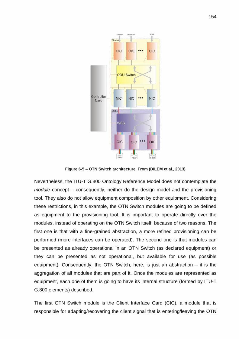
154
Figure 6-5 – OTN Switch architecture. From (DILEM et al., 2013)
Nevertheless, the ITU-T G.800 Ontology Reference Model does not contemplate the
module concept – consequently, neither do the design model and the provisioning
tool. They also do not allow equipment composition by other equipment. Considering
these restrictions, in this example, the OTN Switch modules are going to be defined
as equipment to the provisioning tool. It is important to operate directly over the
modules, instead of operating on the OTN Switch itself, because of two reasons. The
first one is that with a fine-grained abstraction, a more refined provisioning can be
performed (more interfaces can be operated). The second one is that modules can
be presented as already operational in an OTN Switch (as declared equipment) or
they can be presented as not operational, but available for use (as possible
equipment). Consequently, the OTN Switch, here, is just an abstraction – it is the
aggregation of all modules that are part of it. Once the modules are represented as
equipment, each one of them is going to have its internal structure (formed by ITU-T
G.800 elements) described.
The first OTN Switch module is the Client Interface Card (CIC), a module that is
responsible for adapting/recovering the client signal that is entering/leaving the OTN

155
network. Different types of client signals, with different characteristics, can
communicate with the CIC, for instance, 10G-100G Ethernet, MPLS-TP, SDH, and
also lower order OTN signals (DILEM et al., 2013). Figure 6-6 represents, in its left
part, the CIC as presented in (DILEM et al., 2013); and in its right part, the CIC
simplification used in the example here presented. The same display pattern of
Figure 6-6 is adopted for the presentation of all other OTN Switch modules. Note
that, as (DILEM et al., 2013) uses an example with a client signal of type 10 Gigabit
Ethernet, the same client signal is going to be used in the example provided in this
chapter.
Figure 6-6 – Client Interface Card definition
The second OTN Switch module used here is the ODU Switch, which is presented in
Figure 6-7. The ODU Switch is responsible for the digital switching of the ODU
signals inside the OTN Switch. This switching can be configured automatically (by a
control plan, such as OpenFlow, GMPLS, etc.) or manually (by the network operator
intervention) (DILEM et al., 2013).
CIC as defined in Dilem et al. CIC as used in the example
CIC
OD
U2
e

156
Figure 6-7 – ODU Switch and WSS definitions
As can be seen in Figure 6-7, the ODU Switch is differently implemented in (DILEM
et al., 2013) and in the OTN example here defined. While (DILEM et al., 2013)
represents the internal structure of the ODU Switch with a subnetwork, we used the
matrix to implement this module. This was necessary because, as a design decision,
considering that the subnetwork concept definition by the recommendations ITU-T
G.805 and ITU-T G.800 presents ontological deficiencies (BARCELOS, 2011),
subnetworks are not allowed in the provisioning tool. However, as matrices represent
the limit to the recursive partitioning of a subnetwork (ITU-T, 2012a), this substitution
does not constitute a problem. For simplification purposes, the ODU Switch used in
the example has exactly two matrices (one source and one sink), each one with two
pairs of input and output ports.
Also represented in Figure 6-7, the Wavelength Selective Switch (WSS) is the
module in which an optical signal can be routed, protected, added, or dropped
from/to an aggregated WDM signal (DILEM et al., 2013). Just like happens with the
ODU Switch, in this example, for the same reasons, the WSS has matrices in its
internal structure instead of subnetworks.
Another OTN Switch module here used is the Network Interface Card (NIC). This
module is responsible for providing a digital end-to-end path, insert management
ODU Switch as defined in Dilem et al. ODU Switch as used in the example
WSS as defined in Dilem et al. WSS as used in the example
OC
h
WSS
OD
U2
e
OD
U S
wit
ch

157
information and error corrections (Forward Error Correction), and to provide the
functionality (when necessary) of one or more ODU multiplexing stages. It is inside
the NIC that the electrical-optical conversion occurs (DILEM et al., 2013). The NIC’s
internal structure is presented in Figure 6-8.
Figure 6-8 – Network Interface Card definition
As already mentioned, in this example we adopt a client signal of type 10 Gigabit
Ethernet, just like (DILEM et al., 2013). Consequently, the layer structure used in the
example differs from the “pure” OTN layer hierarchy presented in Figure 6-2. In the
example here presented, the ODU layer is divided in two: the ODU2e and the ODUk.
While the CIC and the ODU Switch implement transport functions of the former layer,
the NIC’s first layer is the latter.
The final module of the OTN Switch here used is the Optical Interface Card (OIC),
presented in Figure 6-9. The OIC performs the treatment of the optical signal, i.e., the
NIC as defined in Dilem et al. NIC as used in the example
OD
Uk
OTU
OC
h
NIC

158
multiplexing and demultiplexing of different optical channels in a single fiber, just like
the amplification and the compensation of the dispersion (DILEM et al., 2013).
Figure 6-9 – Optical Interface Card definition
Hereafter, in the figures that illustrate this chapter, the modules presented in this
subsection are going to be presented in a higher abstraction, as independent
equipment. For a better illustration of the network, these equipment are going to be
represented as named colored rectangles, each one with their corresponding
interfaces.
6.1.2 Declared Network and Possible Equipment
As presented in chapter 5, the provisioning tool can accept two network descriptions
as inputs: the declared equipment, which consists of the equipment that are already
operational on the network; and optionally the possible equipment, which consists of
equipment that are available to be used, but that are not installed or operational. Both
the declared equipment and the possible equipment used in the example are going to
be presented and described in this section. The complete specification of these
equipment (i.e., the complete structured text file), however, is not provided in this
OIC as defined in Dilem et al. OIC as used in the example
OM
SO
TS
OIC

159
thesis because of its large size. Just like all other necessary information, the
specifications can be found in the thesis shared folder: https://goo.gl/L1UPv4.
The network formed by the declared equipment, represented in Figure 6-10,
corresponds to the topology presented in Figure 6-1. In this network, four equipment
are available: two OTN Switches and two amplifiers. In addition, the four links in
Figure 6-10 (pm12, pm13, pm24, and pm34) are also declared as equipment.
Figure 6-10 – Declared equipment available in the example
Just like previously said, the OTN Switches (EQ1 and EQ4) are represented by its
modules, here declared as independent equipment. The amplifiers (EQ2 and EQ3)
are single equipment, as well as the four physical media. In summary, the network
presented in Figure 6-10 has 19 declared equipment.
AM
P –
EQ 3
pm12
CIC01
NIC01
OIC01
WSS
ODU Switch
CIC02
OTN
Sw
itch
–EQ
4
CIC01
NIC01
OIC01
WSS
ODU Switch
CIC02
OIC02
OTN
Sw
itch
–EQ
1
pm24
pm13 pm34
AM
P –
EQ 2

160
As can be seen in Figure 6-10 there are resources available and physical bindings
already established to provision a path from equipment EQ1 to EQ4 via EQ3.
However, there are no resources already available on the network for provisioning a
path from EQ1 to EQ4 via EQ2.
The OTN Switches represented in Figure 6-10 are declared with partial capacity.
Regarding this, two considerations can be made. The first one is that their available
slots are empty (i.e., there are no installed modules). In this case, possible
equipment can be used to provide full capacity to the OTN Switches, allowing new
paths. The second consideration is that the available slots have installed modules
that are not operational. In this second case, the not operational equipment constitute
possible equipment, not declared ones. The possible equipment made available in
this example are represented in Figure 6-11. They are one CIC (CIC P1), two NICs
(NIC P1 and NIC P2), and one OIC (OIC P1).
Figure 6-11 – Possible equipment available in the example
Once the network to be provisioned is presented with its declared equipment and
possible equipment, in subsection 6.1.3, the desired information transfer is
presented.
6.1.3 Information Transfer to be Provisioned
The example consists on the provisioning of an information transfer (i.e., a
connection), represented as an orange dotted line in the topological view of the
network in Figure 6-12, from EQ1 to EQ4.
NICP1
OICP1
NICP2

161
Figure 6-12 – Topological representation of the paths to be provisioned
In the example, the information transfer presented in the left part of Figure 6-12 must
be protected in the electrical domain. To implement the desired connection, two
paths must be provisioned: (i) a working path, which is the main information transfer
path, and (ii) a protection path, which is an alternative in case of failure of the working
path. Both the working path and the protection path must share the same source and
destination interfaces (i.e., the same INT_SOURCE and INT_SINK). It can be
observed, in the right part of Figure 6-12, the restrictions that apply to the paths to be
provisioned.
The first path to be provisioned is the working path, in section 6.2. The provision of
this path must demand a minimum intervention in the network, using the
infrastructure already available. On this path, the priority to be set is the use of the
minimum number of new bindings. In addition, the provisioning of this path must use
the automatic provisioning mode available in the KBS.
The second path to be provisioned, the protection path, intends to protect the
information transfer of the working path in the electrical domain. Therefore, it is
desired that the two provisioned paths do not share the same optical fibers because,
in case of a failure (e.g., a broken fiber) in one of the paths, the information transfer
can continue on the other provisioned path. The provisioning of the protection path,
presented in section 6.3, must be performed in the manual mode of the provisioning
tool.
EQ2
EQ1
EQ3
EQ4
pm12
pm34
pm13 pm24
EQ1 CIC 01(INT_SOURCE)
EQ4 CIC 01(INT_SINK)
Path Mode Requirement
Working Path AutomaticMinimum number
of new bindings
Protection Path ManualDifferent fibers
from working path

162
6.2 AUTOMATIC PROVISIONING OF THE WORKING PATH
At the beginning of the provisioning process, it is necessary to provide as input the
inference and the consistency models, as well as the declared and possible
equipment declarations. This first step can be seen in Figure 6-13.
Figure 6-13 – Loading of the knowledge base, declared, and possible equipment
Figure 6-13 is a screen capture of the provisioning tool execution. Other images from
this section and from the next section are also screen captures, however, some of
them present modifications and arrangements to better illustrate the software
execution. Besides the content of the images here presented, the software also
provides intermediate execution and processing information, which are not presented
because they are not relevant for the comprehension of the paths’ provisioning. In
addition, marks and other editions are also included in some images when it is
necessary to highlight part of the information presented.
Back to the provisioning of the working path, the second step is the selection of the
source interface (INT_SOURCE) and the destination interface (INT_SINK), as can be
observed in Figure 6-14. The selected source and sink interfaces to be provisioned
are, respectively, in_int_so_EQ1_CIC_01 (from equipment EQ1_CIC_01) and
out_int_sk_EQ4_CIC_01 (from equipment EQ4_CIC_01).

163
Figure 6-14 – INT_SOURCE, INT_SINK, and provisioning mode selection
As can be seen in the last line of Figure 6-14, the two provisioning modes are made
available to the user, which must choose one. According to the requirements defined
in subsection 6.1.3, the provisioning path must be automatically provisioned and,
hence, this mode was here selected.
Two important steps of the automatic path provisioning are presented in Figure 6-15.
This figure represents the definition of the restrictions that apply in the path finding
process, as well as the selection of the priority.
Figure 6-15 – Restrictions and priority definitions
In Figure 6-15, it can be observed that the only restriction imposed was the maximum
number of paths to be returned to the user, which was set as 2. By the end of the
path finding process, there are going to be at most two paths to be evaluated by the
user, which may choose the best option among them. No maximum value was
defined for the other three restrictions available (number of interfaces in a path,
number of new bindings, and number of interfaces from possible equipment). In
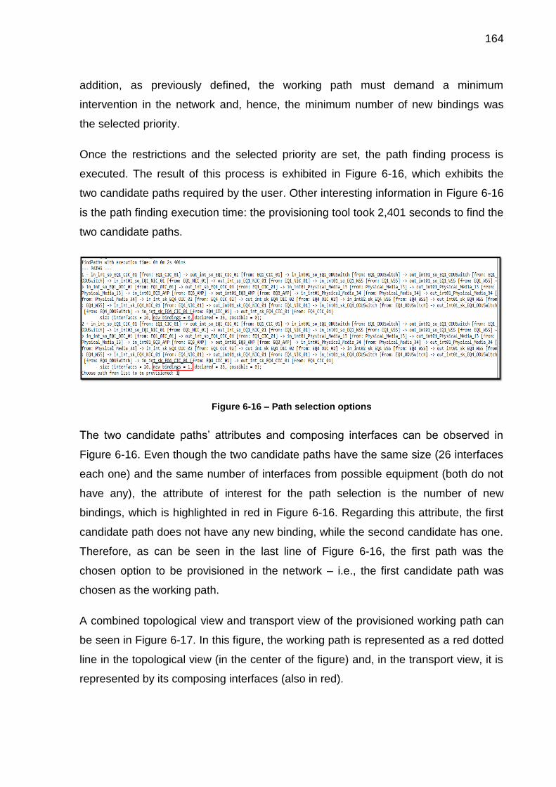
164
addition, as previously defined, the working path must demand a minimum
intervention in the network and, hence, the minimum number of new bindings was
the selected priority.
Once the restrictions and the selected priority are set, the path finding process is
executed. The result of this process is exhibited in Figure 6-16, which exhibits the
two candidate paths required by the user. Other interesting information in Figure 6-16
is the path finding execution time: the provisioning tool took 2,401 seconds to find the
two candidate paths.
Figure 6-16 – Path selection options
The two candidate paths’ attributes and composing interfaces can be observed in
Figure 6-16. Even though the two candidate paths have the same size (26 interfaces
each one) and the same number of interfaces from possible equipment (both do not
have any), the attribute of interest for the path selection is the number of new
bindings, which is highlighted in red in Figure 6-16. Regarding this attribute, the first
candidate path does not have any new binding, while the second candidate has one.
Therefore, as can be seen in the last line of Figure 6-16, the first path was the
chosen option to be provisioned in the network – i.e., the first candidate path was
chosen as the working path.
A combined topological view and transport view of the provisioned working path can
be seen in Figure 6-17. In this figure, the working path is represented as a red dotted
line in the topological view (in the center of the figure) and, in the transport view, it is
represented by its composing interfaces (also in red).

165
Figure 6-17 – Combined topological and transport view of the provisioned working path
In Figure 6-17, it can be seen that the working path goes from EQ1 to EQ4 through
EQ3. Hence, as the protection path must use different fibers from the working path, it
obligatorily has to use EQ2 and its related physical media (pm12 and pm24). In
addition, it can be observed that no interfaces from possible equipment were used in
the working path provisioning.
Finally, by the end of the provisioning of the working path, as can be seen in Figure
6-18, the provisioning tool validates the current knowledge base’s state and returns
this information to the user. In case of success of the validation, the user can choose
to provision another path or not. As we intend to provision the protection path, in this
example, the answer was positive, as can be seen in Figure 6-18.
AM
P –
EQ 3
pm12
CIC01
NIC01
OIC01
WSS
ODU Switch
CIC02
OTN
Sw
itch
–EQ
4
CIC01
NIC01
OIC01
WSS
ODU Switch
CIC02
OIC02
OTN
Sw
itch
–EQ
1
pm24
pm13 pm34
AM
P –
EQ 2
EQ2EQ1
EQ3 EQ4
pm12
pm34
pm13 pm24

166
Figure 6-18 – Validation checking and new provisioning option
Differently from the provisioning of the working path, the provisioning of the
protection path has to be done with the manual provisioning mode, according to the
requirements presented in subsection 6.1.3.
6.3 MANUAL PROVISIONING OF THE PROTECTION PATH
The provisioning of the protection path begins with the selection of the source and
destination of the provisioning (i.e., INT_SOURCE and INT_SINK, respectively).
However, differently from the first executed provisioning (i.e., the working path
provisioning), the already provisioned interfaces are informed to the user. This
difference is represented by red marks in Figure 6-19.
Figure 6-19 – Manual provisioning
However, as we want to provision a protection path, the same interfaces of the last
example were selected: in_int_so_EQ1_CIC_01 (from equipment EQ1_CIC_01) and
out_int_sk_EQ4_CIC_01 (from equipment EQ4_CIC_01). These interfaces are,
respectively, INT_SOURCE and INT_SINK. This selection, as well as the selection of

167
the manual provisioning mode (a previously defined requirement of the protection
path provisioning), is presented in Figure 6-19.
The manual provisioning mode consists in iterative steps in which the user is
required to choose the input interfaces (VAR_INs) and the output interfaces
(VAR_OUTs) that compose the path to be provisioned until a selected output
interface equals the defined destination interface (INT_SINK). All iterations of the
provisioning of the protection path are presented in Figure 6-20 and in Figure 6-23.
These figures contain selected parts of the provisioning result mounted together in
chronological order. The first part of the protection path’s provisioning is represented
in Figure 6-20, which corresponds to the selection of the interfaces of EQ1.
Figure 6-20 – First part of the manual provisioning (provisioning of EQ1 modules)
As can be seen in Figure 6-20, while the interfaces are being selected by the user,
the provisioning tool presents the current provisory path (i.e., the path that is being
mounted) with all its composing interfaces and attributes.
As the working path must be protected in the electrical domain, the protection path to
be provisioned uses the ODU Switch to duplicate the information transfer and hence
implement the protection. The use of a second output port of this equipment (i.e., the
port which is not being used by the working path) in the protection path is
represented by the red mark in Figure 6-20. In addition, Figure 6-20 illustrates that
not only declared equipment was used in the provisioning of the protection path,

168
possible equipment were also required in order to allow the information transfer
through the desired optical fibers. The selection of interfaces from possible
equipment is represented in orange in Figure 6-20 and in Figure 6-22.
The purple mark in Figure 6-20 represents an important limitation on the provisioning
tool. This mark highlights an example of invalid interface that is offered to the user as
a correct provisioning candidate. However, the candidate interface is invalid with
relation to the domain, not with relation to the software algorithm. I.e., even though
the candidate interfaces respect all the restrictions and definitions established in the
provisioning tool algorithm, it does not respect a domain aspect: the geographical
position of the equipment. Without this important consideration, the software cannot
know the distance between the network equipment, which may be kilometers away
one from the other. In the example highlighted in purple in Figure 6-20, an interface
from EQ4 is exhibited as a candidate to be directly bound to an interface from EQ1,
what clearly does not respect the topology presented in Figure 6-1.
An interesting example of this limitation of the provisioning tool would be observed if,
instead of selecting the minimum number of new bindings in the automatic
provisioning of the working path, we had selected the minimum number of interfaces
as the priority. In such case, the first path that would be returned to the user by the
tool path finding process is represented in Figure 6-21.

169
Figure 6-21 – Invalid network provisioning
As can be seen in Figure 6-21, the returned path would have only 18 interfaces (and
also 6 new bindings, and 8 interfaces from possible equipment), while the path
actually provisioned has 26 interfaces. However, this smaller path is invalid and,
hence, it should not be considered by the provisioning tool user. The suggested path
is invalid because it does not respect the topology presented in Figure 6-1: it does
not use any amplifier to transfer information from EQ1 to EQ4 and directly binds
interfaces from these equipment.
The suggestion of false candidate interfaces caused by the provisioning tool
limitation in dealing with the geographical position of equipment is recurrent and can
be found more times in Figure 6-20 and in Figure 6-22. This problem forces the
network operator to evaluate carefully all the provisioning results (in both automatic
and manual modes) in order to assure a valid provisioning. The solution of this
problem is considered a future work and it involves the redesign of the provisioning
tool. As the Ontology Reference Model already provides the necessary attributes and
concepts for this solution, a second version of the design model should reflect these
pm12
CIC01
NIC01
OIC01
WSS
ODU Switch
CIC02
OTN
Sw
itch
–EQ
4
CIC01
NIC01
OIC01
WSS
ODU Switch
CIC02
OIC02
OTN
Sw
itch
–EQ
1
pm24
AM
P –
EQ 2
NICP1
OICP1

170
necessary concepts, as well as the implementation should be modified to treat them.
These concepts are the latitude and longitude attributes that every Transport
Processing Function and Matrix have in the Ontology Reference Model, as well as
the site concept (a site aggregates equipment in a given location) that can be found
in the site ontology presented in subsection 4.3.3.
Back to the provisioning of the protection path, in Figure 6-22 the reminder of the
provisioning iterations can be observed. In this provisioning process, the requirement
that the protection path must not share any optical fiber with the working path was
considered. As can be seen in Figure 6-17, the working path uses pm13 and pm34,
and, because of that, the protection path must use pm12 and pm24. The use of these
two physical media is represented in Figure 6-22 by blue marks, indicating the use of
the interfaces of the Physical Media Equipment in the intermediate path (i.e., the
protection path that was being mounted).

171
Figure 6-22 – Second part of the manual provisioning
The red mark in Figure 6-22 indicates that the electrical protection that began in the
ODU Switch of EQ1 is terminated in the ODU Switch of EQ4. In addition, as in Figure
6-20, the orange marks in Figure 6-22 shows that interfaces from possible equipment
were used in the provisioning of the protection path.
Finally, by the selection of INT_SOURCE as VAR_OUR, represented in the last line
of Figure 6-22, the path is complete and the consistency of the knowledge base’s
resulting state is verified by the reasoner. When no problem is found, the provisioning
process is finished and the user must answer if he or she would like to provision
another path. In case of a negative answer, the performed network provisioning is
saved as an OWL file, which is made available to the user. These last steps are
represented in Figure 6-23.

172
Figure 6-23 – End of provisioning process
The final topological view of the network provisioning is presented in Figure 6-24. As
it can be seen, the working path goes from EQ1 to EQ4 through EQ3, passing on
pm13 and pm34, while the protection path goes from the same source to the same
destination by a different route, passing through EQ2 instead of EQ3, using pm12
and pm24. Moreover, Figure 6-24 shows that the two paths have an intersection,
which is represented as an orange dotted line.
Figure 6-24 – Topological representation of the provisioned paths
The same provisioned network can be seen in Figure 6-25 using a transport view
instead of a topological view. Note that the network contains both the declared
equipment and the possible equipment, as both were used in the network
provisioning. This figure also represents, with the same colors used in Figure 6-24,
the two provisioned paths (by means of its composing interfaces). In addition,
possible equipment are differentiated from the declared equipment by a red border in
Figure 6-25.
Figure Type
Working Path
Protection Path
Intersection of
Paths
EQ2
EQ1
EQ3
EQ4
pm12
pm34
pm13 pm24
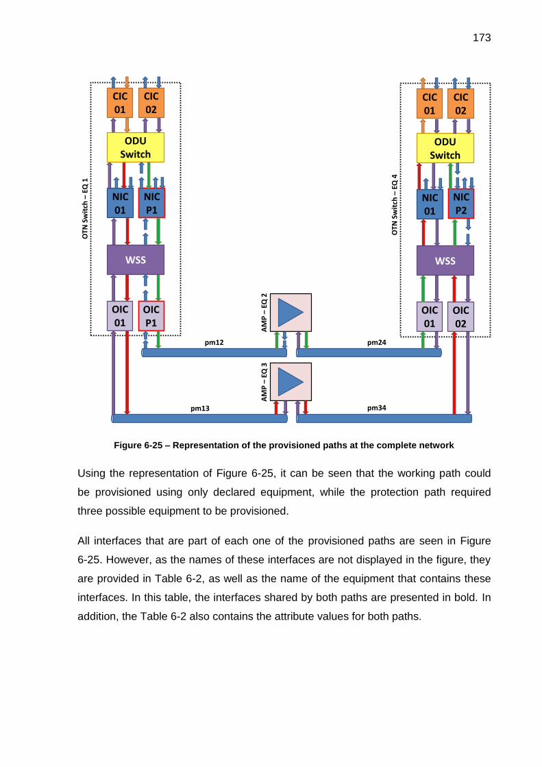
173
Figure 6-25 – Representation of the provisioned paths at the complete network
Using the representation of Figure 6-25, it can be seen that the working path could
be provisioned using only declared equipment, while the protection path required
three possible equipment to be provisioned.
All interfaces that are part of each one of the provisioned paths are seen in Figure
6-25. However, as the names of these interfaces are not displayed in the figure, they
are provided in Table 6-2, as well as the name of the equipment that contains these
interfaces. In this table, the interfaces shared by both paths are presented in bold. In
addition, the Table 6-2 also contains the attribute values for both paths.
AM
P –
EQ 3
pm12 pm24
pm13 pm34
AM
P –
EQ 2
CIC01
NIC01
OIC01
WSS
ODU Switch
CIC02
OTN
Sw
itch
–EQ
1
NICP1
OICP1
OTN
Sw
itch
–EQ
4
CIC01
NIC01
OIC01
WSS
ODU Switch
CIC02
OIC02
NICP2

174
Table 6-2 – Paths' attributes and interfaces
Working Path Protection Path
Num. of Interfaces
26 26
New bindings
0 7
Int. of Poss. Eq.
0 6
Inte
rfac
es
an
d b
elo
ng
ing
eq
uip
me
nt
na
me
s
1. in_int_so_EQ1_CIC_01
from: EQ1_CIC_01 2. out_int_so_EQ1_CIC_01
from: EQ1_CIC_01 3. in_int01_so_EQ1_ODUSwitch
from: EQ1_ODUSwitch 4. out_int01_so_EQ1_ODUSwitch
from: EQ1_ODUSwitch 5. in_int01_so_EQ1_NIC_01
from: EQ1_NIC_01 6. out_int_so_EQ1_NIC_01
from: EQ1_NIC_01 7. in_int01_so_EQ1_WSS
from: EQ1_WSS 8. out_int01_so_EQ1_WSS
from: EQ1_WSS 9. in_int_so_EQ1_OIC_01
from: EQ1_OIC_01 10. out_int_so_EQ1_OIC_01
from: EQ1_OIC_01 11. in_int01_Physical_Media_13
from: Physical_Media_13 12. out_int01_Physical_Media_13
from: Physical_Media_13 13. in_int01_EQ3_AMP
from: EQ3_AMP 14. out_int01_EQ3_AMP
from: EQ3_AMP 15. in_int01_Physical_Media_34
from: Physical_Media_34 16. out_int01_Physical_Media_34
from: Physical_Media_34 17. in_int_sk_EQ4_OIC_02
from: EQ4_OIC_02 18. out_int_sk_EQ4_OIC_02
from: EQ4_OIC_02 19. in_int02_sk_EQ4_WSS
from: EQ4_WSS 20. out_int01_sk_EQ4_WSS
from: EQ4_WSS 21. in_int_sk_EQ4_NIC_01
from: EQ4_NIC_01 22. out_int01_sk_EQ4_NIC_01
from: EQ4_NIC_01 23. in_int01_sk_EQ4_ODUSwitch
from: EQ4_ODUSwitch 24. out_int01_sk_EQ4_ODUSwitch
from: EQ4_ODUSwitch 25. in_int_sk_EQ4_CIC_01
from: EQ4_CIC_01 26. out_int_sk_EQ4_CIC_01
from: EQ4_CIC_01
1. in_int_so_EQ1_CIC_01
from: EQ1_CIC_01 2. out_int_so_EQ1_CIC_01
from: EQ1_CIC_01 3. in_int01_so_EQ1_ODUSwitch
from: EQ1_ODUSwitch 4. out_int02_so_EQ1_ODUSwitch
from: EQ1_ODUSwitch 5. in_int01_so_POSSIBLE_NIC_P1
from: POSSIBLE_NIC_P1 6. out_int_so_POSSIBLE_NIC_P1
from: POSSIBLE_NIC_P1 7. in_int02_so_EQ1_WSS
from: EQ1_WSS 8. out_int02_so_EQ1_WSS
from: EQ1_WSS 9. in_int_so_POSSIBLE_OIC_P1
from: POSSIBLE_OIC_P1 10. out_int_so_POSSIBLE_OIC_P1
from: POSSIBLE_OIC_P1 11. in_int01_Physical_Media_12
from: Physical_Media_12 12. out_int01_Physical_Media_12
from: Physical_Media_12 13. in_int01_EQ2_AMP
from: EQ2_AMP 14. out_int01_EQ2_AMP
from: EQ2_AMP 15. in_int01_Physical_Media_24
from: Physical_Media_24 16. out_int01_Physical_Media_24
from: Physical_Media_24 17. in_int_sk_EQ4_OIC_01
from: EQ4_OIC_01 18. out_int_sk_EQ4_OIC_01
from: EQ4_OIC_01 19. in_int01_sk_EQ4_WSS
from: EQ4_WSS 20. out_int02_sk_EQ4_WSS
from: EQ4_WSS 21. in_int_sk_POSSIBLE_NIC_P2
from: POSSIBLE_NIC_P2 22. out_int01_sk_POSSIBLE_NIC_P2
from: POSSIBLE_NIC_P2 23. in_int02_sk_EQ4_ODUSwitch
from: EQ4_ODUSwitch 24. out_int01_sk_EQ4_ODUSwitch
from: EQ4_ODUSwitch 25. in_int_sk_EQ4_CIC_01
from: EQ4_CIC_01 26. out_int_sk_EQ4_CIC_01
from: EQ4_CIC_01
To conclude this section, it is important to mention that the provisioning tool and all
the files that are necessary to reproduce the example here presented can be found in
the thesis shared folder: https://goo.gl/L1UPv4.

175
6.4 DISCUSSION ON THE PROVISIONING TOOL PERFORMANCE
In this section, an overview about the provisioning tool performance is provided.
However, first, it must be emphasized that performance is not a requirement of the
software and is out of the thesis scope. Hence, this issue will not be here addressed
in depth – some performance information is provided so the user can have a better
comprehension about the provisioning tool.
To perform an evaluation of the provisioning tool execution time, the total
provisioning time is split in its composing parts, which are:
i. Include Time: the time to include all instances from the input specification in
the knowledge base;
ii. Reasoning Time: the reasoner’s execution time after the loading of the
instances in the knowledge base;
iii. Path Finding Time: the time to execute the automatic path finding and return
the possible candidate paths to the user;
iv. Overhead Time: is the processing time not directly related to the network
provisioning activities, calculated from total time minus the previous three
measured times.
Once again, the total provisioning time is the sum of its four composing parts. In this
section, the total time is measured from the include time to the end of the path finding
time. I.e., the time to apply the object properties that represent the path provisioning,
the time to perform the last consistency checking, and the time to save the OWL file
are not evaluated in this section.
To execute a set of tests, a specific Java software was developed to evaluate the
performance of the provisioning tool. Although not in the scope of this thesis, the
tester is provided in the thesis shared folder.
The network presented in Figure 6-26 was used in the performance test here
presented. This network has, as possible equipment, its lowest layer with four
equipment: two source equipment and two sink equipment. All these equipment are
composed of exactly one adaptation function (with one input and one output) bound

176
with a termination function (also with one input and one output). This file also
contains the declaration of two physical media.
Figure 6-26 – Test network with N layers
The upper layers of the test network, presented in Figure 6-26, are specified as
declared equipment. The test consists in variations of the number of layers declared
in the possible equipment file, ranging from 1 to 3 layers. In all tests, the upper layers
are always composed of four equipment: two source equipment and two sink
equipment. All these equipment are composed of exactly one adaptation function
(with one input and one output) bound with a termination function (also with one input
and one output), which is bound to a matrix (with three ports – one input, when
source, or two inputs, when sink).
In the test here performed, any restrictions were defined (i.e., there are no
restrictions on the number of paths, their sizes, number of new bindings, or number
of interfaces from possible equipment). The resulting times of the execution of the
test for the network presented in Figure 6-26, with N ranging from 1 to 3, is presented
in Table 6-3.
L1L0
L2LN
SourcePort
SinkPort
Fixd
e p
ort
ion
in a
ll te
sts
(file
: p
oss
ible
)P
ort
ion
th
at a
re in
cre
ase
d in
te
sts
(file
: d
ecl
are
d)
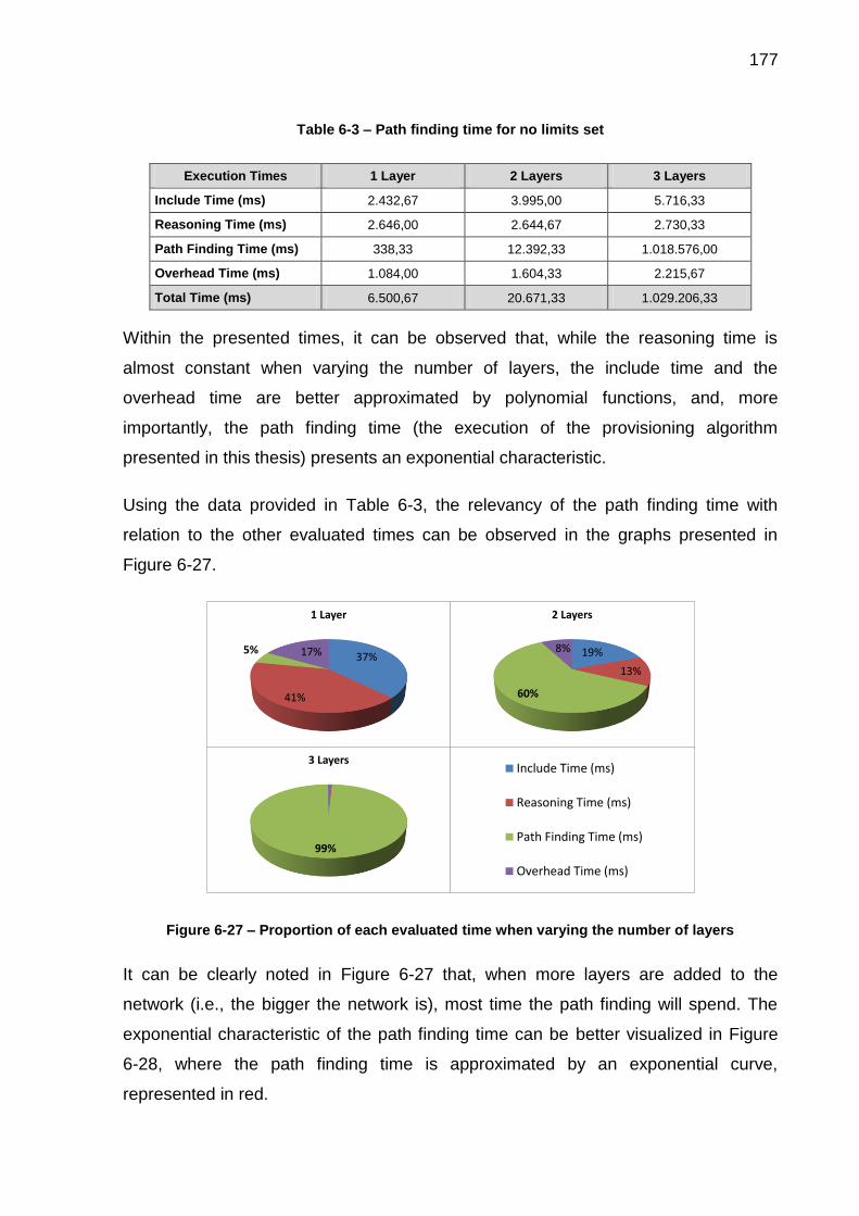
177
Table 6-3 – Path finding time for no limits set
Execution Times 1 Layer 2 Layers 3 Layers
Include Time (ms) 2.432,67 3.995,00 5.716,33
Reasoning Time (ms) 2.646,00 2.644,67 2.730,33
Path Finding Time (ms) 338,33 12.392,33 1.018.576,00
Overhead Time (ms) 1.084,00 1.604,33 2.215,67
Total Time (ms) 6.500,67 20.671,33 1.029.206,33
Within the presented times, it can be observed that, while the reasoning time is
almost constant when varying the number of layers, the include time and the
overhead time are better approximated by polynomial functions, and, more
importantly, the path finding time (the execution of the provisioning algorithm
presented in this thesis) presents an exponential characteristic.
Using the data provided in Table 6-3, the relevancy of the path finding time with
relation to the other evaluated times can be observed in the graphs presented in
Figure 6-27.
Figure 6-27 – Proportion of each evaluated time when varying the number of layers
It can be clearly noted in Figure 6-27 that, when more layers are added to the
network (i.e., the bigger the network is), most time the path finding will spend. The
exponential characteristic of the path finding time can be better visualized in Figure
6-28, where the path finding time is approximated by an exponential curve,
represented in red.
37%
41%
5% 17%
1 Layer
19%
13%
60%
8%
2 Layers
99%
3 Layers 1 LayerInclude Time (ms)
Reasoning Time (ms)
Path Finding Time (ms)
Overhead Time (ms)

178
Figure 6-28 – Exponential characteristic of the path finding when no restrictions are defined
The exponential running time here presented can also be found in the work
presented in (KUIPERS; DIJKSTRA, 2009), which defined path finding algorithms for
multi-layer graphs. The work there presented also demonstrated the NP-complete
nature of the multi-layer path finding problem, which a step of the network
provisioning process (DIJKSTRA et al., 2009). However, it is important to highlight
that, as presented in section 2.5, the problem there addressed differs from the one
we address in this thesis.
The problems related to this exponential characteristic of the path finding times when
dealing with no limitations can be observed, for example, when the number of layers
in the test is set to four. In this case, the provisioning tool reports an
OutOfMemoryError: Java heap space. However, it is important to highlight that in a
real provisioning case, it is unlikely that the provisioning tool would be used to find all
paths from two points or that no restrictions would be defined. In real situations, the
network operator will need just some options to evaluate which is the best path to be
provisioned. Hence, the network operator (i.e., the provisioning tool user) would use
the restrictions available (number of paths, size of the path, number of new bindings,
and number of interfaces from possible equipment) in order to just evaluate the paths
that most fit in the provisioning strategy.
The use of the restrictions allows the provisioning tool execution in networks with a
higher number of elements and in a smaller time. The software performance
338,33
12.392,33
1.018.576,00
y = 5,3891e4,0049x
1E+02
1E+03
1E+04
1E+05
1E+06
1E+07
1E+08
1E+09
1E+10
1 2 3 4 5
Pat
h F
ind
ing
Tim
e (
ms)
Number of Layers
Path Finding Times (ms)

179
improvement can be observed when restrictions are set, as also tested in the
provisioning tool. As the performed test involves many executions of the provisioning
tool and considering that this is a complementary discussion, only the results of the
test are here presented to illustrate the restrictions’ importance. The complete test
information and its results can be found in the thesis shared folder. Six categories of
restrictions were created for this other test. These categories are:
NL: unlimited, where no limit is defined;
L1: limited maximum number of paths;
L2: limited maximum number of interfaces in a path;
L3: limited maximum number of new bindings;
L4: limited maximum number of interfaces from possible equipment;
AL: limited defined for all parameters.
In the NL category, just one test was performed, as there are no restrictions to be
varied (i.e., it is the same test already presented in this section). For the other five
categories, five executions were performed. The restrictions are related to the
executions’ number: the higher the number, fewer restrictions were imposed. The
mean total provisioning time of all categories tested can be visualized in Figure 6-29.
Figure 6-29 – Restriction tests representing the restrictions’ use importance
0
200
400
600
800
1.000
1.200
1 2 3 4 5
Tota
l Ex
ecu
tio
n T
ime
(m
s)
Tho
usa
nd
s
Number of the Test
Test Results by Category
L1 L2 L3 L4 AL NL

180
It can be observed in Figure 6-29 that the highest provisioning time was observed in
the NL category. For all other categories, as more restrictions are imposed, the path
finding times are smaller – this happens because fewer paths are found.
To conclude, all tests were performed on a Windows 8.1 Pro 64 bits, in an Intel Core
i5-3570 CPU with 3.40 GHz and 8,00 GB of memory. No other special pre
configurations were made for the test.

181
7 CONCLUSION
Provisioning is an important activity in the configuration of networks. The ITU-T
Recommendation M.3400 defines network provisioning as the "procedures which are
necessary to bring an equipment into service, not including installation" (ITU-T,
2000a). Resource and service provisioning are recent challenges in communication
network planning (MATERA; LISTANTI; PIÓRO, 2015) and are important activities in
paradigms of the future networking, like service-oriented networks (ESCALONA et
al., 2011), cloud networking (HOUIDI et al., 2011a), and network virtualization
(SCHAFFRATH et al., 2009).
In this thesis chapter 2, the most recent studies in service provisioning and in
infrastructure provisioning were presented, as well as the works that have already
used ontologies somehow for network provisioning. In addition, related works
proposed in the literature concerning network models and path finding in technology-
independent multi-layer transport networks were presented and discussed.
Five major problems related to the infrastructure layer’s provisioning solutions were
pointed out: (i) the absence of formal semantics and lack of interoperability, (ii) the
need for automation, (iii) the limited consideration of network equipment, (iv) the
technology dependence, and (v) the limited layering considerations. Regarding these
important identified problems, this thesis investigated if the use of semantic
technologies, especially ontologies, can solve the lack of interoperability in the
transport network area and if these technologies can be the basis for a computational
solution that can provision technology-independent multi-layer transport networks
considering the equipment states. The adopted hypothesis was that the use of a well-
founded Ontology Reference Model of the Recommendation ITU-T G.800 is able to
give precise semantics to the transport network area, allowing interoperability, and
that the use of this Ontology Reference Model in a rigid ontology-based development
method can generate a software that is able to provision technology-independent
multi-layer transport networks considering the equipment states. Regarding this
hypothesis, the thesis general objective was to develop an ontology-based

182
provisioning solution for technology-independent multi-layer transport networks. To
accomplish the general objective, three specific objectives were defined:
SO1: the development of an Ontology Reference Model for technology-
independent multi-layer transport networks based on a recognized
international standard, the Recommendation ITU-T G.800, and built with an
expressive well-founded ontology language to the definition of precise
semantics and to allow communication, learning, and interoperation;
SO2: the development of a semantically improved network model for the
provisioning of technology-independent multi-layer transport networks, here
called OWL Computational Ontology. This computational artifact must be
generated from the Ontology Reference Model (SO1) through a rigid ontology
engineering; and
SO3: the development of an ontology-based network provisioning knowledge-
based system that uses the OWL Computational Ontology (SO2) as a
knowledge base. This system must be able to perform circuit provisioning and
connection provisioning on a technology-independent multi-layer transport
network, considering the equipment state.
To accomplish the desired objectives, the MDA ontology-based development method
used to develop the provisioning tool knowledge base was presented in this thesis
chapter 3. This method is composed of three phases, each one with a respective
artifact: the Ontology Reference Model, the design model, and the OWL
Computational Ontology. The three phases of the ontology-based development
method were described, as well as their respective implementation technologies.
The Recommendation ITU-T G.800 Ontology Reference Model built to define precise
semantics to the transport network area, eliminating semantic deficiencies and
allowing interoperation, was presented in chapter 4. The Recommendation ITU-T
G.800, which is the standard that describes the functional architecture of transport
networks in a technology-independent way, was modeled using OntoUML. OntoUML
is a highly expressive well-founded ontology language that has been successfully
employed in a number of industrial projects in several different domains
(ALBUQUERQUE; GUIZZARDI, 2013). In chapter 4, the thesis SO1 was achieved.

183
The use of the Ontology Reference Model in the MDA ontology-based development
method results in the knowledge base of the desired KBS provisioning tool –
accomplishing the thesis SO2. The provisioning tool, divided into its main parts (its
knowledge base, reasoning engine, and domain logics), is presented in chapter 5. As
desired, this software is able to provision technology-independent multi-layer
transport networks considering the networks equipment states. Hence, the thesis
SO3 was also achieved.
In chapter 5, conceptual and computational issues of the implemented knowledge-
based system for transport networks provisioning were demonstrated on technology-
independent examples. However, the technology independence is one of the
software main advantages, allowing it to be used in a multitude of ITU-T G.800
compliant transport network technologies. To provide a more realistic use of the
provisioning tool, as well as to highlight its use in a specific transport network
technology, in chapter 6, the provisioning tool was applied to an Optical Transport
Network (OTN). In this chapter, two paths were provisioned, a working path and a
protection path, using, respectively, the automatic and the manual provisioning
modes available in the KBS provisioning tool.
Considering that (1) an Ontology Reference Model of the Recommendation ITU-T
G.800 was created, and that it was built with a well-founded ontology language within
a rigid ontology engineering, resulting in a model capable of giving precise semantics
to the transport network area, and thus allowing interoperability. Considering also
that (2) a rigid ontology-based development method was here used to (3) generate a
KBS provisioning tool that is able to provision technology-independent multi-layer
transport networks aware of the network’s equipment states. As well as considering
that this tool was tested in a technology-specific example, being able to achieve the
desired results (i.e., to perform the circuit and connection provisioning of an OTN
transport network), it can be concluded that the thesis hypothesis is confirmed.

184
7.1 THESIS MATERIAL
We provide in this thesis a shared folder with all the material related to the thesis.
The links to access this folder are:
https://goo.gl/L1UPv4 – Shortened link
https://drive.google.com/folderview?id=0B5G6gMOt9j5lQ1JyVHhGOEJmenM
&usp=sharing – Complete link
In the shared folder, the reader can find:
the Recommendation ITU-T G.800 OntoUML Ontology Reference Model,
the OntoUML design model,
the OWL Consistency Model and the OWL Inference Model,
the provisioning tool Java file
the Java performance tester, test information and results discussed in section
6.4,
the declared equipment and the possible equipment specifications used in the
example of chapter 6, and
the specification described in this thesis Appendix II.
7.2 FUTURE WORKS
This thesis intended to demonstrate that an Ontology Reference Model can define
precise semantics to the transport network area and that it can be used in a rigid
ontology-based development method to generate a software that is able to provision
technology-independent multi-layer transport networks considering the networks
equipment states. Positive results indicate that the objective was achieved. However,
both the Ontology Reference Model and the provisioning tool can be significantly
improved in future works to cover better the intended domain, as well as to be
extended to other domains and applications. Regarding this, the first category of
future works to be here presented concerns the already known limitations of the
provisioning tool, which were presented in chapters 5 and 6.

185
One of the most important limitations of the current version of the provisioning tool is
the absence of a graphical interface. The development of a graphic interface can
provide a visual representation of the network to be provisioned and would
significantly improve the user’s comprehension about what is happening in the paths’
provisioning, performing then an important role and, hence, being desired for future
implementations.
Designed to provide an easy network provisioning to the user, the current version of
the provisioning tool has a restriction on the representation of the complete transport
network domain. The software ease of use is important; however, by adopting this
restriction, the software becomes limited because it cannot operate on all real
networks. I.e., currently, the provisioning tool can only operate on the real networks
that use the same concepts that are available in it. An example of this restriction can
be observed for the transport processing functions. While the ITU-T G.800 OntoUML
Ontology Reference Model formalizes all these concepts, the design model
formalizes just a reduced set of them (e.g., it does not represent the Layer Processor
Function). We encourage here the creation of a second version of the provisioning
tool with less domain restrictions. However, in the development of this second
version, the tradeoff that exists between the quantity of concepts to be managed and
the execution time (reasoning time, path finding time, etc.) must be observed. The
exponential characteristic of the current implementation of the path finding process is
a limitation of the provisioning tool, preventing its execution in large networks.
Regarding this tradeoff, optimization techniques may be employed to allow the
execution of the provisioning tool in an acceptable time.
Still concerning simplifications implemented in the current provisioning tool version,
another future work is a strong treatment on the rules that are verified by the
provisioning tool in the case of network protection, which is performed in matrices.
The current implementation, as presented in chapter 5, does not verify all possible
cases of occurrences of this situation and may lead to problems in more complex
networks.
The last case of future work that can be classified in the category of already known
limitations of the provisioning tool is the non-representation of the geographical
positions of the networks equipment. This problem leads to situations where invalid

186
candidate interfaces are offered to the user during the network provisioning. As
already discussed and exemplified in chapter 6, solution proposals involve the use of
the geographical position attribute that is present in the ITU-T G.800 Reference
Model, as well as the use of concepts from the Simple Site Ontology.
Regarding the provisioning tool algorithm improvement, a better treatment of the
problematic situations in the manual provisioning can be thought as future works.
When no VAR_IN candidate or no VAR_OUT candidate is found, the algorithm could
be more robust and, instead of finishing the provisioning algorithm, it could make a
rollback to the last valid state. The verification of possible interfaces one step further,
to see if the displayed interfaces have other possible bindings or not, is another
possibility.
Another interesting future work is the implementation of a software to generate valid
network declarations to be used as input files in the network provisioning. The
software, a graphical equipment studio, could use the same design model used in the
provisioning tool to perform semantic validations. Together with a syntactical
validation, the generation of valid inputs can be guaranteed. This input generator
could be implemented coupled or not to the provisioning tool. In addition, a visual
interface for this software would considerably help the declaration of networks. A
graphical equipment editor for transport networks have already been developed in
(ANHOLETTI, 2014). Although based on the same standard of the provisioning tool,
the equipment editor presented in (ANHOLETTI, 2014) does not use the same
metamodel of the work here presented and, hence, it cannot be directly coupled to
this work. We encourage modifications on the editor presented in (ANHOLETTI,
2014) to make it compatible with the provisioning tool.
This version of the provisioning tool uses a three layered ontology structure,
represented in Figure 4-4, to create the design model that is then transformed to the
provisioning tool knowledge base. As future works, other ontology layers could be
developed and coupled to the Ontology Reference Model, increasing its domain
representation (vertically, including new levels of abstractions about the concepts
already defined; or horizontally, including new technologies and concepts). Once in
the Ontology Reference Model, the new ontologies could be used in the development
of a new and extended design model, which could be transformed to the provisioning

187
tool knowledge base. An example of a possible extension of the provisioning tool is
the modeling of network standards that deal with specific technologies. A candidate
technology-specific recommendation to be modeled is the Recommendation ITU-T
G.872 (ITU-T, 2012b), which specifies the Optical Transport Networks. Attributes that
can be included to deal with specific transport technologies are suggested in
(DIJKSTRA et al., 2008). For the lower layers, (DIJKSTRA et al., 2008) says that
power levels, signal degradation, cable length, and optical dispersion should be
used; and for higher layers, the modeling of delay and jitter are suggested.
The provisioning tool here defined claims to perform network provisioning. However,
network provisioning can be interpreted in two forms: in the first one, the provisioning
is performed in the software network abstraction; and in the second form, the
provisioning is performed in the real physical network. As presented in chapter 5, this
tool is able to perform the first form of provisioning: its results are physical and logical
relations inside the software network model, saved as an OWL output file. As the
software does not have any direct connection to the real network to be provisioned,
the network operator must replicate the results of the tool provisioning process in the
real network to be configured. The automated configuration of the real network can
be implemented in future developments of the provisioning tool. In these newer
versions, the provisioning tool can output network configuration files that can be
manipulated the network – e.g., by using the YANG data model and the NETCONF
protocol (SCHONWALDER; BJORKLUND; SHAFER, 2010). Such procedure would
eliminate intermediate human errors and reduce the network provisioning time. With
this future implementation, the network tool can be classified in the group of fully
automated provisioning mechanisms defined in (DOVERSPIKE; YATES, 2012) and
presented in this thesis in subsection 2.2.2.
To conclude this thesis, the last future work here suggested is the possible
integration of the provisioning tool with NDL and its related tools and languages. The
provisioning tool could benefit from the extensive experience that the NDL language
and related tools have, as well as it could help to improve the semantics of NDL.

188
7.3 PUBLICATIONS
Five works were published during the development of this thesis. All published works
concerns the use of ontologies and were cited in this document. The relation
between four of these works and the models used in this thesis can be found in
Figure 7-1.
Figure 7-1 – Contributions of the published works to the thesis
In this subsection, we present in chronological order the list of the published works
and their corresponding abstracts.
ODISE 2012 – Identification of Semantic Anti-Patterns in Ontology-Driven
Conceptual Modeling via Visual Simulation (SALES; BARCELOS; GUIZZARDI,
2012)
The construction of large-scale reference conceptual models and ontologies is a
complex engineering activity. To develop high quality models, a modeler must have
the support of expressive engineering tools such as theoretically well-founded
modeling languages and methodologies, ontological patterns and computational
environments. Patterns and Anti-Patterns are known to be an efficient way to reuse
knowledge from experts’ successful past experiences. This paper proposes a set of
Semantic Anti-Patterns for ontology engineering. These anti-patterns capture error
prone modeling decisions that can result in the creation of models that allow for
unintended model instances (representing undesired state of affairs). The anti-
OWL G.800 ProvisioningComputational Ontology
OntoUML ITU-T G.800Ontology Reference Model
OOTOSModel TransformationOntoUML G.800
ProvisioningDesign Model
Identification of Semantic Anti-Patterns in Ontology-Driven Conceptual Modeling via Visual Simulation
An Automated Transformation from OntoUML to OWL and SWRL
An Ontology Reference Model for Normative Acts
On the Importance of Truly Ontological Distinctions for Standardizations: a Case Study in the Domain of Telecommunications

189
patterns presented here have been empirically elicited through an approach of
ontology conceptual models validation via visual simulation.
Ontobras 2013 – An Automated Transformation from OntoUML to OWL and
SWRL (BARCELOS et al., 2013)
OntoUML and OWL are ontology languages appropriated to different knowledge
representation levels. In order to have better knowledge representation and
reasoning capabilities in OWL ontologies, an Ontology Engineering should be used –
which corresponds to the transformation of a conceptual model ontology language,
such as OntoUML, to a computational ontology language, such as OWL. This paper
aims to bridge the expressivity gap between these languages through a Model Driven
Architecture automated transformation from OntoUML to OWL with SWRL rules that
contributes to (i) make easier the OWL creation from OntoUML, (ii) eliminate the
human errors in this process, (iii) improve the resultant OWL ontology semantics.
Ontobras 2013 – Na Ontology Reference Model for Normative Acts
(BARCELOS; GUIZZARDI; GARCIA, 2013)
Normative Acts are important legislative and regulatory documents made by different
governmental organs. Every year, a huge amount of information is provided in
Normative Acts by these organs without control, i.e., there is no effective way to
verify redundancies, inconsistencies, cross-impact and ambiguities. In this paper, we
propose a domain ontology for Normative Acts based on official documents (the
Brazilian Constitution and the Redaction Manual of the Presidency of the Republic)
as a reference model that can be used to improve communication, interoperation and
automation of Normative Acts. The reference model is built with a highly expressive
well-founded language within a methodology that ensures its quality.
CNSM 2014 – An Ontology-based Approach to Improve SNMP Support for
Autonomic Management (MONTEIRO et al., 2014)
The SNMP protocol remains a broadly adopted technology in the Internet
management framework and its MIB was proposed to guarantee interoperation. In
order to enable the management of new equipment, the human manager must
compile the correlated MIB file (MIB description) and choose the right objects to

190
manage an implicit knowledge. This paper presents an ontology-based approach and
a Semantic SNMP extension to improve the framework's autonomic support.
Computer Standards & Interfaces 2016 – On the Importance of Truly
Ontological Distinctions for Standardizations: a Case Study in the Domain of
Telecommunications (BARCELOS et al., 2016)
Standards are documents that aim to define norms and common understanding of a
subject by a group of people. In order to accomplish this purpose, these documents
must define its terms and concepts in a clear and unambiguous way. Standards can
be written in two different ways: by informal specification (e.g. natural language) or
formal specification (e.g. math-based languages or diagrammatic ones). Remarkable
papers have already shown how well-founded ontology languages provide resources
for the specification's author to better distinguish concepts and relations meanings,
resulting in a better specification. This paper has the objective to expose the
importance of truly ontological distinctions for standardizations. To achieve this
objective, we evaluate a math-based formal specification, in Z notation, using a well-
founded ontology language for a telecommunications case study, the ITU-T
Recommendation G.805. The results confirm that truly ontological distinctions are
essential for clear and unambiguous specifications.

191
8 BIBLIOGRAPHY
ABBURU, S. A Survey on Ontology Reasoners and Comparison. International Journal of Computer Applications, v. 57, n. 17, p. 33–39, 2012.
ABOSI, C. E.; NEJABATI, R.; SIMEONIDOU, D. A Novel Service Composition Mechanism for the Future Optical Internet. Journal of Optical Communications and Networking, v. 1, n. 2, p. A106, 1 Jul. 2009.
AGOULMINE, N. et al. Challenges for Autonomic Network Management 1st IEEE International Workshop on Modelling Autonomic Communications Environments (MACE). Anais...2006
ALBUQUERQUE, A.; GUIZZARDI, G. An ontological foundation for conceptual modeling datatypes based on semantic reference spaces IEEE 7th International Conference on Research Challenges in Information Science (RCIS). Anais...Paris: IEEE, 2013
AMELLER, D. Non-Functional Requirements as drivers of Software Architecture Design. [s.l.] Universitat Politècnica de Catalunya, 2014.
ANHOLETTI, A. F. Um Editor Gráfico para Redes de Transporte Baseado na Recomendação ITU-T G.800. Vitória, Brazil: Federal University of Espírito Santo, 2014.
ANTONIOU, G.; HARMELEN, F. VAN. Web Ontology Language: OWL. In: STAAB, S.; STUDER, R. (Eds.). Handbook on Ontologies. Second Edi ed. [s.l.] SpringerVerlag Berlin Heidelberg, 2009. p. 91–110.
ASSMAN, U.; ZSCHALER, S.; WAGNER, G. Ontologies, Meta-models, and the Model-Driven Paradigm. In: CALERO, C.; RUIZ, F.; PIATTINI, M. (Eds.). Ontologies for Software Engineering and Software Technology. [s.l.] Springer Berlin Heidelberg, 2006. p. 249–273.
ATKINSON, C.; KUHNE, T. Model-Driven Development: a Metamodeling Foundation. IEEE Software, v. 20, n. 5, p. 36–41, 2003.
AZODOLMOLKY, S. et al. Integrated OpenFlow–GMPLS control plane: an overlay model for software defined packet over optical networks. Optics Express, v. 19, n. 26, p. B421, 12 Dec. 2011.
BALDINE, I. et al. The Missing Link: Putting the Network in Networked Cloud Computing ICVCI09: International Conference on the Virtual Computing Initiative. Anais...2009
BARCELOS, P. P. F. et al. OOTN -An Ontology Proposal for Optical Transport Networks International Conference on Ultra Modern Telecommunications & Workshops (ICUMT’09). Anais...St. Petersburg, Russia: IEEE, 2009
BARCELOS, P. P. F. Análise Arquitetural, Ontológica e Proposta de Modelo de Referência para a Recomendação ITU-T G. 805. Vitória: Federal University of Espírito Santo, 2011.
BARCELOS, P. P. F. et al. Ontological Evaluation of the ITU-T Recommendation

192
G.805 18th International Conference on Telecommunications. Anais...IEEE, May 2011
BARCELOS, P. P. F. et al. An Automated Transformation from OntoUML to OWL and SWRL (M. P. Bax, M. B. Almeida, R. Wassermann, Eds.) Ontobras. Anais...Belo Horizonte, Brazil: 2013
BARCELOS, P. P. F. et al. On the importance of truly ontological distinctions for standardizations: A case study in the domain of telecommunications. Computer Standards & Interfaces, v. 44, p. 28–41, 2016.
BARCELOS, P. P. F.; GUIZZARDI, R. S. S.; GARCIA, A. S. An Ontology Reference Model for Normative Acts (M. P. Bax, M. B. Almeida, R. Wassermann, Eds.) Ontobras. Anais...Belo Horizonte, Brazil: 2013
BAUMAN, B. T. Prying Apart Semantics and Implementation: Generating XML Schemata directly from ontologically sound conceptual models Balisage: The Markup Conference 2009. Anais...Montréal, Canada: Balisage Series on Markup Technologies, 2009
BERNERS-LEE, T.; HENDLER, J.; LASSILA, O. The Semantic Web. Scientific American, v. 284, n. 5, p. 28–37, 2001.
BLAU, B. et al. Provisioning of Service Mashup Topologies Proceedings of the 16th European Conference on Information Systems. Anais...2008
BOWEN, J. P. Formal Specification and Documentation using Z: A Case Study Approach. Rev. 2003 ed. London: International Thomson Computer Press, 1996.
BUREK, P. et al. A top-level ontology of functions and its application in the Open Biomedical Ontologies. Bioinformatics, v. 22, n. 14, p. e66–e73, 2006.
CALHEIROS, R. N. et al. CloudSim: a toolkit for modeling and simulation of cloud computing environments and evaluation of resource provisioning algorithms. Software: Practice and Experience, v. 41, n. 1, p. 23–50, Jan. 2011.
CAMPI, A.; CALLEGATI, F. Network Resource Description Language2009 IEEE Globecom Workshops. Anais...IEEE, Nov. 2009
CAROLO, F. P.; BURLAMAQUI, L. Improving Web Content Management with Semantic Technologies Semantic Technology Conference (SemTech). Anais...San Francisco, USA: 2011
CARROLL, J. J. et al. Jena: Implementing the Semantic Web Recommendations Proceedings of the 13th international World Wide Web conference on Alternate track papers & posters - WWW Alt. ’04. Anais...New York, New York, USA: ACM Press, 2004
CHAMANIA, M.; JUKAN, A. A survey of inter-domain peering and provisioning solutions for the next generation optical networks. IEEE Communications Surveys & Tutorials, v. 11, n. 1, p. 33–51, 2009.
CHOWDHURY, N. M. M. K.; BOUTABA, R. A survey of network virtualization. Computer Networks, v. 54, n. 5, p. 862–876, Apr. 2010.
CHRISTODOULOPOULOS, K.; TOMKOS, I.; VARVARIGOS, E. Spectrally/bitrate flexible optical network planning 36th European Conference and Exhibition on Optical Communication. Anais...IEEE, Sep. 2010

193
CLEARY, D.; DANEV, B.; DONOGHUE, D. O. Using Ontologies to Simplify Wireless Network Configuration Proceedings of the 1st International Workshop Formal Ontologies Meet Industry, FOMI 2005. Anais...Verona, Italy: 2005
COLE, C. R. 100-Gb/s and beyond transceiver technologies. Optical Fiber Technology, v. 17, n. 5, p. 472–479, Oct. 2011.
DAOUADJI, A. et al. Ontology-Based Resource Description and Discovery Framework for Low Carbon Grid Networks 2010 First IEEE International Conference on Smart Grid Communications. Anais...IEEE, Oct. 2010
DENTLER, K. et al. Comparison of Reasoners for large Ontologies in the OWL 2 EL Profile. Semantic Web, v. 2, n. 2, p. 71–87, 2011.
DIJKSTRA, F. et al. Introduction to ITU-T Recommendation G. 805 SNE technical report SNE-UVA-2007-01. Amsterdam, The Netherlands: [s.n.], 2007.
DIJKSTRA, F. et al. A multi-layer network model based on ITU-T G.805. Computer Networks, v. 52, n. 10, p. 1927–1937, 2008.
DIJKSTRA, F. et al. A path finding implementation for multi-layer networks. Future Generation Computer Systems, v. 25, n. 2, p. 142–146, 2009.
DIJKSTRA, F. Framework for Path Finding in Multi-Layer Transport Networks. Netherlands: Faculteit der Natuurwetenschappen, Wiskunde en Informatica (FNWI), Universiteit van Amsterdam (UvA), 2009.
DILEM, M. et al. Proposta De Arquitetura OTN Switch Segundo as Recomendações ITU-T SBrT 2013. Anais...Fortaleza, CE, Brazil: Sociedade Brasileira de Telecomunicações, 2013
DOUCETTE, J.; GROVER, W.; GIESE, P. Physical-Layer p-Cycles Adapted for Router-Level Node Protection: A Multi-Layer Design and Operation Strategy. IEEE Journal on Selected Areas in Communications, v. 25, n. 5, p. 963–973, Jun. 2007.
DOVERSPIKE, R. D.; YATES, J. Optical Network Management and Control. Proceedings of the IEEE, v. 100, n. 5, p. 1092–1104, May 2012.
DUAN, Q.; YAN, Y.; VASILAKOS, A. V. A Survey on Service-Oriented Network Virtualization Toward Convergence of Networking and Cloud Computing. IEEE Transactions on Network and Service Management, v. 9, n. 4, p. 373–392, Dec. 2012.
DURAK, U.; MA MUTYA ICIO LU, G.; O U T N, . Domain Analysis for Reusable Trajectory Simulation Euro SIW’05. Anais...2005
DUTTA, R.; KAMAL, A. E.; ROUSKAS, G. N. (EDS.). Traffic Grooming for Optical Networks. [s.l.] Springer Science+Business Media, 2008.
ESCALONA, E. et al. GEYSERS: A novel architecture for virtualization and co-provisioning of dynamic optical networks and IT services 2011 Future Network & Mobile Summit. Anais...Warsaw: IEEE, 2011
FAJJARI, I.; AYARI, M.; PUJOLLE, G. VN-SLA: A Virtual Network Specification Schema for Virtual Network Provisioning 2010 Ninth International Conference on Networks. Anais...IEEE, 2010

194
FALBO, R. DE A.; GUIZZARDI, G.; DUARTE, K. C. An Ontological Approach to Domain Engineering. Proceedings of the 14th international conference on Software engineering and knowledge engineering - SEKE ’02, SEKE ’02. p. 351–358, 2002.
FAWAZ, W. et al. Service level agreement and provisioning in optical networks. IEEE Communications Magazine, v. 42, n. 1, p. 36–43, Jan. 2004.
FETTKE, P.; LOOS, P. Ontological Analysis of Reference Models. In: GREEN, P. F.; ROSEMANN, M. (Eds.). Business Systems Analysis with Ontologies. [s.l.] IGI Global, 2005. p. 56–81.
FIELDING, J. M. et al. Ontological Theory for Ontological Engineering: Biomedical Systems Information Integration Ninth International Conference on the Principles of Knowledge Representation and Reasoning (AMIA 2004). Anais...2004
FORDE, A. N.; FOX, M. S. A Telecommunication & Innovation Ontology for Global City Indicators (ISO 37120). Toronto, ON, Canada: [s.n.], 2015.
FORTUNE, S. Equivalence and generalization in a layered network model. Journal of Computer and System Sciences, p. 1–28, 2015.
FRANKEL, D. S. Model Driven Architecture: Applying MDA to Enterprise Computing. Indianapolis, Indiana: Wiley Publishing, Inc, 2003.
GARCÍA-ESPÍN, J. A. et al. Logical Infrastructure Composition Layer, the GEYSERS Holistic Approach for Infrastructure Virtualisation TERENA Networking Conference (TNC-2012). Anais...Ghent University, Department of Information technology: 2012
GAŠEVIĆ, D.; DJURIĆ, D.; DEVEDŽIĆ, V. Model Driven Engineering and Ontology Development. 2nd. ed. Berlin: Springer, 2009.
GAŠEVIĆ, D.; KAVIANI, N.; MILANOVIĆ, M. Ontologies and Software Engineering. In: STAAB, S.; STUDER, R. (Eds.). Handbook on Ontologies. Berlin, Heidelberg: Springer Berlin Heidelberg, 2009. p. 593–615.
GHIJSEN, M. et al. Towards an Infrastructure Description Language for Modeling Computing Infrastructures 2012 IEEE 10th International Symposium on Parallel and Distributed Processing with Applications (ISPA). Anais...Leganes: IEEE, 2012
GHIJSEN, M. et al. A Semantic-Web Approach for Modeling Computing Infrastructures. Computers & Electrical Engineering, v. 39, n. 8, p. 2553–2565, 2013.
GOMAA, H. Software Modeling and Design: UML, Use Cases, Patterns, and Software Architectures. Cambridge: Cambridge University Press, 2011.
GÓMEZ-PÉREZ, A.; FERNÁNDEZ-LÓPEZ, M.; CORCHO, O. Ontological Engeenering. [s.l.] Springer-Verlag London Berlin Heidelberg, 2004.
GOZDECKI, J. et al. Methods of Network Resource Provisioning for the Future Internet IIP Initiative. Telecommunication Systems, 19 Mar. 2015.
GRINGERI, S.; BITAR, N.; XIA, T. J. Extending software defined network principles to include optical transport. IEEE Communications Magazine, v. 51, n. 3, p. 32–40,

195
Mar. 2013.
GRUBER, T. R. A Translation Approach to Portable Ontology Specifications. Knowledge Acquisition, v. 5, n. 2, p. 199–220, Jun. 1993.
GUARINO, N. Formal Onthology and Information Systems Proceedings of the First International Conference on Formal Ontologies in Information Systems (FIOS’98). Anais...Trento, Italy: IOS Press, 1998
GUERSON, J. et al. OntoUML Lightweight Editor: A Model-Based Environment to Build, Evaluate and Implement Reference Ontologies 2015 IEEE 19th International Enterprise Distributed Object Computing Workshop. Anais...IEEE, Sep. 2015
GUINARD, D. et al. Interacting with the SOA-Based Internet of Things: Discovery, Query, Selection, and On-Demand Provisioning of Web Services. IEEE Transactions on Services Computing, v. 3, n. 3, p. 223–235, Jul. 2010.
GUIZZARDI, G. Ontological Foundations for Structural Conceptual Models. Enschede, The Netherlands: Universal Press, 2005.
GUIZZARDI, G. On Ontology, ontologies, Conceptualizations, Modeling Languages, and (Meta)Models. Proceedings of the 2007 conference on Databases and Information Systems IV: Selected Papers from the Seventh International Baltic Conference, Frontiers in Artificial Intelligence and Applications. v. 155, p. 18–39, 2007.
GUIZZARDI, G. et al. On the importance of truly ontological distinctions for ontology representation languages: An industrial case study in the domain of oil and gas. Enterprise, Business-Process and Information Systems Modeling, p. 224–236, 2009.
GUIZZARDI, G.; SALES, T. P. Detection, Simulation and Elimination of Semantic Anti-patterns in Ontology-Driven Conceptual Models. Conceptual Modeling-ER 2014, Lecture Notes in Computer Science. v. 8824, p. 363–376, 2014.
GUIZZARDI, G.; WAGNER, G. Tutorial: Conceptual Simulation Modeling with Onto-UML (C. Laroque et al., Eds.)Proceedings of the 2012 Winter Simulation Conference (WSC). Anais...Berlin: IEEE, 2012
HAILPERN, B.; TARR, P. Model-driven development: The good, the bad, and the ugly. IBM Systems Journal, v. 45, n. 3, p. 451–461, 2006.
HAM, J. VAN DER et al. Challenges of an Information Model for Federating Virtualized Infrastructures 2011 5th International DMTF Academic Alliance Workshop on Systems and Virtualization Management (SVM). Anais...IEEE, 2011a
HAM, J. VAN DER et al. D2.2: First information and data models. [s.l: s.n.], 2011b.
HAM, J. VAN DER et al. The Network Markup Language (NML): A Standardized Network Topology Abstraction for Inter-domain and Cross-layer Network Applications, 2013.
HAM, J. VAN DER et al. Trends in Computer Network Modeling Towards the Future Internet eprint arXiv:1402.3951. Anais...2014
HAPPEL, H.; SEEDORF, S. Applications of Ontologies in Software Engineering Proc. of Workshop on Sematic Web Enabled Software Engineering (SWESE) on the

196
ISWC. Anais...2006
HITZLER, P. et al. OWL 2 Web Ontology Language Primer (Second Edition), 2012.
HOFFMANN, M.; STAUFER, M. Network Virtualization for Future Mobile Networks: General Architecture and Applications 2011 IEEE International Conference on Communications Workshops (ICC). Anais...IEEE, Jun. 2011
HORROCKS, I. Ontologies and the Semantic Web. Communications of the ACM, v. 51, n. 12, p. 58–67, 2008.
HORROCKS, I.; KUTZ, O.; SATTLER, U. The Even More Irresistible SROIQ. Proc. of the 10th Int. Conf. on Principles of Knowledge Representation and Reasoning (KR2006), p. 57–67, 2006.
HOUIDI, I. et al. Adaptive virtual network provisioning Proceedings of the second ACM SIGCOMM workshop on Virtualized infrastructure systems and architectures - VISA ’10. Anais...New York, New York, USA: ACM Press, 2010
HOUIDI, I. et al. Cloud Service Delivery across Multiple Cloud Platforms 2011 IEEE International Conference on Services Computing. Anais...IEEE, 2011a
HOUIDI, I. et al. Virtual network provisioning across multiple substrate networks. Computer Networks, v. 55, n. 4, p. 1011–1023, Mar. 2011b.
HUANG, J. Service Delivery Framework (SDF) OverviewTM Forum, 2009.
INFINERA CORPORATION. Bandwidth Virtualization Enables a Programmable Optical Network. Sunnyvale, CA: [s.n.], 2007.
ITU-T. ITU-T Recommendation Q.704: Specifications of Signalling System No. 7 – Message transfer partITU-T International Telecommunication Union, 1996.
ITU-T. ITU-T Recommendation M.3400: TMN Management Functions International Telecommunication Union, 2000a.
ITU-T. ITU-T Recommendation G.805: Generic Functional Architecture of Transport Networks International Telecommunication Union, 2000b.
ITU-T. ITU-T Recommendation G.809: Functional Architecture of Connectionless Layer Networks International Telecommunication Union, 2003.
ITU-T. Optical Transport Networks from TDM to Packet, 2010.
ITU-T. Recommendation ITU-T G.800: Unified Functional Architecture of Transport Networks International Telecommunication Union, 2012a.
ITU-T. Recommendation ITU-T G.872: Architecture of optical transport networksInternational Telecommunication Union, 2012b.
ITU-T. Recommendation ITU-T G.798: Characteristics of optical transport network hierarchy equipment functional blocks International Telecommunication Union, 2012c.
JACKSON, D. Alloy: a lightweight object modelling notation. ACM Transactions on Software Engineering and Methodology (TOSEM), v. 11, n. 2, p. 256–290, 2002.
JARRAR, M.; DEMEY, J.; MEERSMAN, R. On Using Conceptual Data Modeling for Ontology Engineering. Journal on Data Semantics I, Lecture Notes in Computer

197
Science Volume 2800. p. 185–207, 2003.
JINNO, M. et al. Spectrum-efficient and scalable elastic optical path network: architecture, benefits, and enabling technologies. IEEE Communications Magazine, v. 47, n. 11, p. 66–73, Nov. 2009.
JIRATTIGALACHOTE, A. et al. Dynamic provisioning strategies for energy efficient WDM networks with dedicated path protection. Optical Switching and Networking, v. 8, n. 3, p. 201–213, 2011.
KALIBATIENE, D.; VASILECAS, O.; GUIZZARDI, G. Transforming Ontology Axioms to Information Processing Rules – An MDA Based Approach (C. Kop et al., Eds.) Proceedings of the Third International Workshop on Ontology, Conceptualization and Epistemology for Information Systems, Software Engineering and Service Science held in conjunction with CAiSE’09 Conference. Anais...Amsterdam, The Netherlands: CEUR Workshop Proceedings, 2009
KANG, Y.-B.; LI, Y.-F.; KRISHNASWAMY, S. Predicting Reasoning Performance Using Ontology Metrics. In: The Semantic Web – ISWC 2012. Lecture Notes in Computer Science. [s.l.] Springer Berlin Heidelberg, 2012. v. 7649p. 198–214.
KELLY, S.; TOLVANEN, J.-P. Domain-Specific Modeling: Enabling Full Code Generation. Hoboken, New Jersey: John Wiley & Sons, Inc., 2008.
KLINKOWSKI, M.; WALKOWIAK, K. Routing and Spectrum Assignment in Spectrum Sliced Elastic Optical Path Network. IEEE Communications Letters, v. 15, n. 8, p. 884–886, 2011.
KNACKSTEDT, R. et al. An Ontology-Based Service Discovery Approach for the Provisioning of Product- Service Bundles 16th European Conference on Information Systems. Anais...Galway, Ireland: 2008
KOMPELLA, K.; REKHTER, Y.; JUNIPER NETWORKS. RFC 4203: OSPF Extensions in Support of Generalized Multi-Protocol Label Switching (GMPLS). [s.l: s.n.], 2005.
KOOIJ, J. G. Ambiguity in Natural Language: An Investigation of Certain Problems in Its Linguistic Description. Foundations of Language, v. 10, n. 4, p. 595–597, 1973.
KOSLOVSKI, G. P.; PRIMET, P. V.-B.; CHARÃO, A. S. VXDL: Virtual Resources and Interconnection Networks Description Language. In: Networks for Grid Applications. [s.l.] Springer, 2009. v. 2p. 138–154.
KOZAT, U.; KOUTSOPOULOS, I.; TASSIULAS, L. Cross-Layer Design for Power Efficiency and QoS Provisioning in Multi-Hop Wireless Networks. IEEE Transactions on Wireless Communications, v. 5, n. 10, p. 3306–3315, Nov. 2006.
KUIPERS, F.; DIJKSTRA, F. Path selection in multi-layer networks. Computer Communications, v. 32, n. 1, p. 78–85, 2009.
LEE, S.; KANG, S. NGSON: features, state of the art, and realization. IEEE Communications Magazine, v. 50, n. 1, p. 54–61, Jan. 2012.
LEHMAN, T. et al. Control Plane Architecture and Design Considerations for Multi-Service, Multi-Layer, Multi-Domain Hybrid Networks 2007 High-Speed Networks Workshop. Anais...IEEE, May 2007
LEVESQUE, H. J.; BRACHMAN, R. J. A Fundamental Tradeoff in Knwoledge

198
Representation and Reasoning (Revised Version). Readings in Knowledge Representation, p. 41–70, 1985.
LIU, L. et al. First Field Trial of an OpenFlow-based Unified Control Plane for Multi-layer Multi-granularity Optical Networks Optical Fiber Communication Conference. Anais...Washington, D.C.: OSA, 2012
LIU, L. et al. OpenSlice: an OpenFlow-based control plane for spectrum sliced elastic optical path networks. Optics Express, v. 21, n. 4, p. 4194, 25 Feb. 2013.
LIU, Q. et al. Hierarchical routing in multi-domain optical networks. Computer Communications, v. 30, n. 1, p. 122–131, Dec. 2006.
LÓPEZ DE VERGARA, J. E. et al. An autonomic approach to offer services in OSGi-based home gateways. Computer Communications, v. 31, n. 13, p. 3049–3058, Aug. 2008.
LÓPEZ DE VERGARA, J. E. et al. Ontology-Based Network Management: Study Cases and Lessons Learned. Journal of Network and Systems Management, v. 17, n. 3, p. 234–254, Sep. 2009.
LOZANO, J. A. et al. Autonomic Provisioning Model for Digital Home Services. In: [s.l: s.n.]. p. 114–119, 2008.
MAES, S. H. Service Delivery Platforms as IT Realization of OMA Service Environment: Service Oriented Architectures for Telecommunications 2007 IEEE Wireless Communications and Networking Conference. Anais...IEEE, 2007
MAGEDANZ, T.; BLUM, N.; DUTKOWSKI, S. Evolution of SOA Concepts in Telecommunications. Computer, v. 40, n. 11, p. 46–50, Nov. 2007.
MARTINEZ, R.; CASELLAS, R.; MUNOZ, R. Experimental validation/evaluation of a GMPLS unified control plane in multi-layer (MPLS-TP/WSON) networks. Optical Fiber Communication Conference and Exposition (OFC/NFOEC), 2012 and the National Fiber Optic Engineers Conference, p. 1–3, 2012.
MASOLO, C. et al. DOLCE: a Descriptive Ontology for Linguistic and Cognitive Engineering. [s.l: s.n.], 2003.
MATERA, F.; LISTANTI, M.; PIÓRO, M. Recent trends in network planning to decrease the CAPEX/OPEX cost. Telecommunication Systems, 19 Mar. 2015.
MCGUIRE, A.; BONENFANT, P. Standards: the blueprints for optical networking. IEEE Communications Magazine, v. 36, n. 2, p. 68–70, 75–8, 1998.
MCKEOWN, N. et al. OpenFlow: enabling innovation in campus networks. ACM SIGCOMM Computer Communication Review, v. 38, n. 2, p. 69, 2008.
MEALY, G. H. Another look at data Proceedings of the November 14-16, 1967, fall joint computer conference on - AFIPS ’67 (Fall). Anais...New York, New York, USA: ACM Press, 1967
MELLOR, S. J.; CLARK, A. N.; FUTAGAMI, T. Model-driven Development: Guest Editors’ Introduction. IEEE Software, v. 20, n. 5, p. 14–18, 2003.
MILTON, S. K.; KAZMIERCZAK, E. An Ontology of Data Modelling Languages: A Study Using a Common-Sense Realistic Ontology. In: WANG, J. (Ed.). Data Warehousing and Mining: Concepts, Methodologies, Tools, and Applications.

199
Hershey, PA, USA: IGI Global, 2008. p. 3194–3211.
MONTEIRO, M. E. et al. Ontology Based Model for The ITU-T Recommendation G.805: Towards the Self-Management of Transport Networks. International journal of computer science & information Technology, v. 2, n. 2, p. 155–170, 2010.
MONTEIRO, M. E. et al. An ontology-based approach to improve SNMP support for autonomic management 10th International Conference on Network and Service Management (CNSM) and Workshop. Anais...Rio de Janeiro, Brazil: IEEE, 2014
MONTI, P. et al. Energy-efficient lightpath provisioning in a static WDM network with dedicated path protection 2011 13th International Conference on Transparent Optical Networks. Anais...IEEE, 2011
NEELAKANTAN, A.; ROTH, B.; MCCALLUM, A. Compositional Vector Space Models for Knowledge Base Completion Proceedings of the 53rd Annual Meeting of the Association for Computational Linguistics and the 7th International Joint Conference on Natural Language Processing (Volume 1: Long Papers). Anais...Stroudsburg, PA, USA: Association for Computational Linguistics, 2015
OBJECT MANAGEMENT GROUP. MDA Guide Version 1.0.1 (J. Miller, J. Mukerji, Eds.), 2003.
PATEL-SCHNEIDER, P. F.; HORROCKS, I. Position paper: a comparison of two modelling paradigms in the Semantic Web. Proceedings of the 15th international conference on World Wide Web, p. 3–12, 2006.
PENG, S. et al. Application-aware and Adaptive Virtual Data Centre Infrastructure Provisioning over Elastic Optical OFDM Networks 39th European Conference and Exhibition on Optical Communication (ECOC 2013). Anais...Institution of Engineering and Technology, 2013
PODOBNIK, V.; TRZEC, K.; JEZIC, G. Context-Aware Service Provisioning in Next-Generation Networks. International Journal of Information Technology and Web Engineering, v. 2, n. 4, p. 41–62, Jan. 2007.
QUIROLGICO, S.; MILLS, K.; MONTGOMERY, D. Deriving Knowledge for the Knowledge Plane, 2003.
RAMASWAMI, R.; SIVARAJAN, K. N.; SASAKI, G. H. Optical Networks - A Practical Perspective. Third Edit ed. [s.l.] Morgan Kaufmann Publishers, 2010.
REKHTER, Y.; LI, T.; HARES, S. RFC 4271: A Border Gateway Protocol 4 (BGP-4). [s.l: s.n.], 2006.
RODRIGUES, C. et al. An ontology for managing network services quality. Expert Systems with Applications, v. 39, n. 9, p. 7938–7946, Jul. 2012.
SALES, T. P.; BARCELOS, P. P. F.; GUIZZARDI, G. Identification of Semantic Anti-Patterns in Ontology-Driven Conceptual Modeling via Visual Simulation. 4th International Workshop on Ontology-Driven Information Systems (ODISE 2012), 2012.
SANCHEZ-LORO, X. et al. Proposal of a clean slate network architecture for ubiquitous services provisioning 2009 First International Conference on Future Information Networks. Anais...IEEE, Oct. 2009
SARAKIS, L. et al. A framework for service provisioning in virtual sensor networks.

200
EURASIP Journal on Wireless Communications and Networking, v. 2012, n. 1, p. 135, 2012.
SCHAFFRATH, G. et al. Network virtualization architecture Proceedings of the 1st ACM workshop on Virtualized infrastructure systems and architectures - VISA ’09. Anais...New York, New York, USA: ACM Press, 2009
SCHONWALDER, J.; BJORKLUND, M.; SHAFER, P. Network configuration management using NETCONF and YANG. IEEE Communications Magazine, v. 48, n. 9, p. 166–173, 2010.
SEDDIKI, M. S.; FRIKHA, M.; SONG, Y.-Q. A non-cooperative game-theoretic framework for resource allocation in network virtualization. Telecommunication Systems, 2015.
SERRANO, J. M. et al. Facilitating Autonomic Management for Service Provisioning using Ontology-Based Functions & Semantic Control NOMS Workshops 2008 - IEEE Network Operations and Management Symposium Workshops. Anais...IEEE, Apr. 2008
SERRANO, J. M.; SERRAT, J.; STRASSNER, J. Ontology-Based Reasoning for Supporting Context-Aware Services on Autonomic Networks 2007 IEEE International Conference on Communications. Anais...IEEE, Jun. 2007
SHEARER, R.; MOTIK, B.; HORROCKS, I. HermiT: A Highly-Efficient OWL Reasoner. OWLED, v. 432, 2008.
SHEN, G.; YANG, Q. From Coarse Grid to Mini-Grid to Gridless: How Much can Gridless Help Contentionless? Optical Fiber Communication Conference/National Fiber Optic Engineers Conference 2011. Anais...Washington, D.C.: OSA, 2011
SONE, Y. et al. Routing and Spectrum Assignment Algorithm Maximizes Spectrum Utilization in Optical Networks 37th European Conference and Exposition on Optical Communications. Anais...Washington, D.C.: OSA, 2011
SOWA, J. F. Knowledge Representation: Logical, Philosophical, and Computational Foundations. 1st. ed. Pacific Grove, CA: Brooks Cole Publishing Co., 2000.
SPIVEY, J. M. An introduction to Z and Formal Specifications. Software Engineering Journal, v. 4, n. 1, p. 40–50, 1989.
STAHL, T. et al. Model-Driven Software Development: Technology, Engineering, Management. [s.l.] John Wiley & Sons, Ltd., 2006.
STEFIK, M. Introduction to Knowledge Systems. 1st ed. ed. [s.l.] Morgan Kaufmann, 1995.
TAKAGI, T. et al. Dynamic Routing and Frequency Slot Assignment for Elastic Optical Path Networks that Adopt Distance Adaptive Modulation Optical Fiber Communication Conference/National Fiber Optic Engineers Conference 2011. Anais...Washington, D.C.: OSA, 2011
U.S. DEPARTMENT OF DEFENSE. Data Modeling Guide (DMG) For An Enterprise Logical Data Model (ELDM) - Version 2.3, 2011.
VAN DER HAM, J. et al. Using the Network Description Language in Optical Networks 2007 10th IFIP/IEEE International Symposium on Integrated Network

201
Management. Anais...Munich: IEEE, 2007
VAN DER HAM, J. et al. A distributed topology information system for optical networks based on the semantic web. Optical Switching and Networking, v. 5, n. 2-3, p. 85–93, 2008.
VAN DER HAM, J. J. et al. Using RDF to describe networks. Future Generation Computer Systems, v. 22, n. 8, p. 862–867, Oct. 2006.
VERGARA, J. E. L. DE et al. Ontologies: giving semantics to network management models. IEEE Network, v. 17, n. 3, p. 15–21, May 2003.
VERGARA, J. E. L. DE; VILLAGRÁ, V. A.; BERROCAL, J. Semantic Management: advantages of using an ontology-based management information meta-model Proceedings of the HP Openview University Association Ninth Plenary Workshop (HP-OVUA’2002). Anais...Böblingen, Germany: 2002
VERGARA, J. E. L. DE; VILLAGRÁ, V. A.; BERROCAL, J. Benefits of Using Ontologies in the Management of High Speed Networks. In: High Speed Networks and Multimedia Communications. [s.l.] Springer Berlin Heidelberg, 2004. p. 1007–1018.
VRDOLJAK, L. et al. The AMiGO-Mob: Agent-based middleware for group-oriented mobile service provisioning 10th International Conference on Telecommunications, 2009. ConTEL 2009. Anais...Zagreb, Croatia: IEEE, 2009
W3C OWL WORKING GROUP. OWL 2 Web Ontology Language Document Overview (Second Edition), 2012.
WAND, Y.; STOREY, V. C.; WEBER, R. An ontological analysis of the relationship construct in conceptual modeling. ACM Transactions on Database Systems, v. 24, n. 4, p. 494–528, 1999.
WAND, Y.; WEBER, R. On the ontological expressiveness of information systems analysis and design grammars. Information Systems Journal, v. 3, n. 4, p. 217–237, 1993.
WANG, Q.; WANG, B.; GUO, L. Knowledge Base Completion Using Embeddings and Rules (Q. Yang, M. Wooldridge, Eds.) Proceedings of the Twenty-Fourth International Joint Conference on Artificial Intelligence (IJCAI 2015). Anais...Buenos Aires, Argentina: AAAI Press / International Joint Conferences on Artificial Intelligence, 2015
WANG, X. et al. Flexible Virtual Network Provisioning over Distance-Adaptive Flex-Grid Optical Networks Optical Fiber Communication Conference. Anais...Washington, D.C.: OSA, 2014
WONG, A. K. Y. et al. Ontology mapping for the interoperability problem in network management. IEEE Journal on Selected Areas in Communications, v. 23, n. 10, p. 2058–2068, Oct. 2005.
XIA, M. et al. Green Provisioning for Optical WDM Networks. IEEE Journal of Selected Topics in Quantum Electronics, v. 17, n. 2, p. 437–445, Mar. 2011.
XIN, Y. et al. Virtual smart grid architecture and control framework 2011 IEEE International Conference on Smart Grid Communications (SmartGridComm). Anais...Brussels: IEEE, 2011

202
XU, L. et al. A declarative approach to multi-layer path finding based on semantic network descriptions International Conference on Optical Network Design and Modeling, 2009. ONDM 2009. Anais...Braunschweig: IEEE, 2009
YAMAZAKI, E.; TOMIZAWA, M.; MIYAMOTO, Y. 100-Gb/s optical transport network and beyond employing digital signal processing. IEEE Communications Magazine, v. 50, n. 2, p. s43–s49, Feb. 2012.
YURONG HUANG; HERITAGE, J. P.; MUKHERJEE, B. Connection provisioning with transmission impairment consideration in optical WDM networks with high-speed channels. Journal of Lightwave Technology, v. 23, n. 3, p. 982–993, Mar. 2005.
ZHAO, Y. et al. Knowledge base completion by learning pairwise-interaction differentiated embeddings. Data Mining and Knowledge Discovery, 2015.
ZHOU, L. et al. Context-Aware Middleware for Multimedia Services in Heterogeneous Networks. IEEE Intelligent Systems, v. 25, n. 2, p. 40–47, 2010.
ZHU, Z. et al. Dynamic Service Provisioning in Elastic Optical Networks With Hybrid Single-/Multi-Path Routing. Journal of Lightwave Technology, v. 31, n. 1, p. 15–22, 2013.

203
APPENDIX I – SWRL RULES
All eleven Semantic Web Rule Language (SWRL) rules here presented are part of
the design model and are part of the provisioning tool knowledge base.
Table I-1 – Design Model and Inference Model SWRL Rules
ID SWRL Rule
1
Termination_Function(?v1), Termination_Function(?v7), DifferentFrom(?v1,?v7), Port(?v2),
Port(?v3), Port(?v5), Port(?v6), DifferentFrom(?v2,?v3), DifferentFrom(?v2,?v5),
DifferentFrom(?v2,?v6), DifferentFrom(?v3,?v5), DifferentFrom(?v3,?v6), DifferentFrom(?v5,?v6),
Physical_Media(?v4), Layer_Network(?v8), Layer_Network(?v9), componentOf(?v1,?v2),
componentOf(?v4,?v3), componentOf(?v4,?v5), componentOf(?v7,?v6), binds(?v2,?v3),
binds(?v5,?v6), defines(?v1,?v8), defines(?v7,?v9) -> SameAs(?v8,?v9)
2
Termination_Function(?v1), Port(?v2), Port(?v3), DifferentFrom(?v2,?v3),
Adaptation_Function(?v4), Layer_Network(?v8), componentOf(?v1,?v2), componentOf(?v4,?v3),
binds(?v2,?v3), defines(?v1,?v8) -> adapts_from(?v4,?v8)
3
Termination_Function(?v1), Port(?v2), Port(?v3), DifferentFrom(?v2,?v3),
Adaptation_Function(?v4), Layer_Network(?v8), componentOf(?v1,?v2), componentOf(?v4,?v3),
binds(?v2,?v3), adapts_from(?v4,?v8) -> defines(?v1,?v8)
4
Termination_Function(?v7), Port(?v5), Port(?v6), DifferentFrom(?v5,?v6),
Adaptation_Function(?v4), Layer_Network(?v9), componentOf(?v4,?v5), componentOf(?v7,?v6),
binds(?v5,?v6), defines(?v7,?v9) -> adapts_to(?v4,?v9)
5
Termination_Function(?v7), Port(?v5), Port(?v6), DifferentFrom(?v5,?v6),
Adaptation_Function(?v4), Layer_Network(?v9), componentOf(?v4,?v5), componentOf(?v7,?v6),
binds(?v5,?v6), adapts_to(?v4,?v9) -> defines(?v7,?v9)
6
Termination_Function(?v1), Port(?v2), Port(?v3), DifferentFrom(?v2,?v3), Physical_Media(?v4),
Layer_Network(?v8), componentOf(?v1,?v2), componentOf(?v4,?v3), defines(?v1,?v8),
binds(?v2,?v3) -> Layer_Network.isLast(?v8, true)
7 Adaptation_Function(?v4), Layer_Network(?v8), Layer_Network(?v9), DifferentFrom(?v8,?v9),
adapts_from(?v4,?v8), adapts_to(?v4,?v9) -> client_of(?v8,?v9)

204
ID SWRL Rule
8 Port(?v2), Port(?v3), DifferentFrom(?v2,?v3), Interface(?v4), Interface(?v5),
DifferentFrom(?v4,?v5), maps(?v4,?v2), maps(?v5,?v3), binds(?v2,?v3) -> int_binds(?v4,?v5)
9
Equipment(?v1), Equipment(?v6), DifferentFrom(?v1,?v6), Interface(?v4), Interface(?v5),
DifferentFrom(?v4,?v5), componentOf(?v1, ?v4), componentOf(?v6,?v5), int_binds(?v4,?v5) ->
eq_binds(?v1,?v6)
10 Transport_Function(?v1), Port(?v2), Port(?v3), Transport_Function(?v4), componentOf(?v1,?v2),
componentOf(?v4,?v3),binds(?v2,?v3)->tf_binds(?v1,?v4)
11 Matrix(?v1), Layer_Network (?v2), hasLayer(?v1,?v2) -> Layer_Network.isLast (?v2, false)
12
Termination_Function(?v1), Port(?v2), Port(?v3), DifferentFrom(?v2,?v3), Matrix(?v4),
Layer_Network(?v8), componentOf(?v1,?v2), componentOf(?v4,?v3), binds(?v2,?v3),
defines(?v1,?v8) -> hasLayer(?v4,?v8)
13
Termination_Function(?v1), Port(?v2), Port(?v3), DifferentFrom(?v2,?v3), Matrix(?v4),
Layer_Network(?v8), componentOf(?v1,?v2), componentOf(?v4,?v3), binds(?v2,?v3),
hasLayer(?v4,?v8) -> defines(?v1,?v8)
14
Matrix(?v1), Port(?v2), Port(?v3), DifferentFrom(?v2,?v3), Adaptation_Function(?v4),
Layer_Network(?v8), componentOf(?v1,?v2), componentOf(?v4,?v3), binds(?v2,?v3),
hasLayer(?v1,?v8) -> adapts_from(?v4,?v8)
15
Matrix(?v1), Port(?v2), Port(?v3), DifferentFrom(?v2,?v3), Adaptation_Function(?v4),
Layer_Network(?v8), componentOf(?v1,?v2), componentOf(?v4,?v3), binds(?v2,?v3),
adapts_from(?v4,?v8) -> hasLayer(?v1,?v8)
16
Layer_Network (?v1), Adaptation_Function (?v4), Adaptation_Function(?v5), DifferentFrom
(?v4,?v5), Port(?v2), Port(?v3), DifferentFrom (?v2,?v3), componentOf(?v4,?v2),
componentOf(?v5,?v3), binds(?v2,?v3), adapts_from(?v4,?v1) -> adapts_from(?v5,?v1)
17
Layer_Network (?v1), Adaptation_Function (?v4), Adaptation_Function(?v5), DifferentFrom
(?v4,?v5), Port(?v2), Port(?v3), DifferentFrom (?v2,?v3), componentOf(?v4,?v2),
componentOf(?v5,?v3), binds(?v2,?v3), adapts_from(?v5,?v1) -> adapts_from(?v4,?v1)

205
ID SWRL Rule
18
Layer_Network (?v1), Adaptation_Function (?v4), Adaptation_Function(?v5), DifferentFrom
(?v4,?v5), Port(?v2), Port(?v3), DifferentFrom (?v2,?v3), componentOf(?v4,?v2),
componentOf(?v5,?v3), binds(?v2,?v3), adapts_to(?v4,?v1) -> adapts_to(?v5,?v1)
19
Layer_Network (?v1), Adaptation_Function (?v4), Adaptation_Function(?v5), DifferentFrom
(?v4,?v5), Port(?v2), Port(?v3), DifferentFrom (?v2,?v3), componentOf(?v4,?v2),
componentOf(?v5,?v3), binds(?v2,?v3), adapts_to(?v5,?v1) -> adapts_to(?v4,?v1)

206
APPENDIX II – INPUT TXT FILES STRUCTURE
In this appendix, the syntax of the provisioning tool input files is presented. The
provisioning tool has two input files, which are (i) the declared equipment and (ii) the
possible equipment. Together, these equipment compose the network to be
provisioned.
Both input files share the same syntax, which is here specified in Extended Backus-
Naur Form (EBNF). Besides the EBNF description, a visual representation of the
specification syntax is going to be presented using railroad diagrams. Both the
formalization of the syntax and the generation of visual representation were
performed in the Railroad Diagram Generator15.
The equipment declaration (i.e., the input file) is composed of three main parts: the
instance population, the object property population, and the data property population.
The beginning of the file, as well as the separation between its three parts, and the
end of the file are represented by a separator, in this case, the three asterisks (***).
The division of the network description in three parts is represented in Figure II-1.
Figure II-1 – Network declaration parts
As can be seen in Figure II-1, all the declaration parts are optional. An input file
without information does not make sense and, hence, it must be avoided. The
provisioning tool expects correct input files to execute the provisioning. No syntax or
semantic treatments of the inputs are performed by the provisioning tool.
15
http://bottlecaps.de/rr/ui

207
As an example of the description here presented, we are going to present the
complete declaration of the amplifier used in chapter 6 (defined in subsection
6.1.1.2). This amplifier can be visualized in Figure II-2.
Figure II-2 – Amplifier used in the network declaration example
Even though the syntax specification presented in Figure II-1 generates a single file,
we are going to present the amplifier description in three parts in this appendix for
didactical purposes.
The first part of the network declaration is the instance population, presented in
Figure II-3.
Figure II-3 – Instance population definition
In Figure II-3, Class_Name correspond to the OWL classes available in the
provisioning tool knowledge base. The declaration of Instance_Name is case
sensitive. The instance population for the amplifier presented in Figure II-2 can be
seen in Table II-1.
Table II-1 – Amplifier’s instance population
*** Layer_Network: ODU2e, ODUk, OTU, OCh, OMS, OTS; Equipment: AMP;
AM
P
OTS
2 21 1

208
Input_Interface: in_int01_AMP, in_int02_AMP; Output_Interface: out_int01_AMP, out_int02_AMP; AF_Source: af01_so_AMP, af02_so_AMP; AF_Sink: af01_sk_AMP, af02_sk_AMP; TF_Source: tf01_so_AMP, tf02_so_AMP; TF_Sink: tf01_sk_AMP, tf02_sk_AMP; Input: in_af01_so_AMP, in_af01_sk_AMP, in_tf01_so_AMP, in_tf01_sk_AMP, in_af02_so_AMP, in_af02_sk_AMP, in_tf02_so_AMP, in_tf02_sk_AMP; Output: out_af01_so_AMP, out_af01_sk_AMP, out_tf01_so_AMP, out_tf01_sk_AMP, out_af02_so_AMP, out_af02_sk_AMP, out_tf02_so_AMP, out_tf02_sk_AMP;
The second part of the declaration is the object property declaration, which can be
seen in Figure II-4. This declaration defines the relation between the network
elements.
Figure II-4 – Object property population definition
As represented in Figure II-4, the object property declaration is composed of the
property to be set between two instances and these two instances, which are named
source and target. The amplifier’s object property declaration can be seen in Table
II-2.
Table II-2 – Amplifier’s object property population
*** client_of: (ODU2e, ODUk), (ODUk, OTU), (OTU, OCh), (OCh, OMS), (OMS, OTS); componentOf: (AMP , in_int01_AMP), (AMP , out_int01_AMP), (AMP , in_int02_AMP), (AMP , out_int02_AMP); adapts_from: (af01_so_AMP , OMS), (af01_sk_AMP , OMS), (af02_so_AMP , OMS), (af02_sk_AMP , OMS); adapts_to: (af01_so_AMP , OTS), (af01_sk_AMP , OTS), (af02_so_AMP , OTS), (af02_sk_AMP , OTS); defines: (tf01_so_AMP , OTS), (tf01_sk_AMP , OTS), (tf02_so_AMP , OTS), (tf02_sk_AMP , OTS); componentOf: (AMP , af01_so_AMP), (AMP , af01_sk_AMP), (AMP , af02_so_AMP), (AMP ,

209
af02_sk_AMP), (AMP , tf01_so_AMP), (AMP , tf01_sk_AMP), (AMP , tf02_so_AMP), (AMP , tf02_sk_AMP); componentOf: (af01_so_AMP , in_af01_so_AMP), (af01_so_AMP , out_af01_so_AMP), (af01_sk_AMP , in_af01_sk_AMP), (af01_sk_AMP , out_af01_sk_AMP), (tf01_so_AMP , in_tf01_so_AMP), (tf01_so_AMP , out_tf01_so_AMP), (tf01_sk_AMP , in_tf01_sk_AMP), (tf01_sk_AMP , out_tf01_sk_AMP), (af02_so_AMP , in_af02_so_AMP), (af02_so_AMP , out_af02_so_AMP), (af02_sk_AMP , in_af02_sk_AMP), (af02_sk_AMP , out_af02_sk_AMP), (tf02_so_AMP , in_tf02_so_AMP), (tf02_so_AMP , out_tf02_so_AMP), (tf02_sk_AMP , in_tf02_sk_AMP), (tf02_sk_AMP , out_tf02_sk_AMP); binds: (in_af01_sk_AMP , out_tf01_sk_AMP), (out_af01_sk_AMP , in_af01_so_AMP), (out_af01_so_AMP , in_tf01_so_AMP), (in_af02_sk_AMP , out_tf02_sk_AMP), (out_af02_sk_AMP , in_af02_so_AMP), (out_af02_so_AMP , in_tf02_so_AMP); maps: (in_int01_AMP , in_tf01_sk_AMP), (out_int01_AMP , out_tf01_so_AMP), (in_int02_AMP , in_tf02_sk_AMP), (out_int02_AMP , out_tf02_so_AMP);
Finally, the last part of the description concerns the declaration of the data properties,
which are related to the attributes of the network. The specification of this declaration
can be seen in Figure II-5. Just like the object property population, this declaration is
composed of the property to be set between two instances and these two instances.
Figure II-5 – Data property population definition
As can be seen in the design model, the only class attribute defined is the isLast
Boolean attribute of the class Layer Network and, hence, this is the only data
property available. In the amplifier example, the OTS layer must be set as the last
layer, as can be observed in Table II-3.
Table II-3 – Data properties' declaration
*** Layer_Network.isLast: (OTS, true, boolean); ***
The concatenation of the three parts of the amplifier example here presented results
in its complete description. The text file with this description can be found in the
thesis shared folder.

210
In the declarations, spaces and line breaks in the input files are ignored. In addition,
the user must know that every individual declared with a different name is set as
disjoint from each other in the knowledge base. If a same individual is declared twice
(for example, in two different classes), only one individual is created in the knowledge
base.