Embed Size (px)
Citation preview
7/27/2019 20120612 - poços de caldas
http://slidepdf.com/reader/full/20120612-pocos-de-caldas 1/8
PROCESS CONTROLChinese Journal of Chemical Engineering , 20(6) 1113—1120 (2012)
The Design and Control of Distillation Column with Side Reactors for
Chlorobenzene Production*
BO Cuimei (薄翠梅)1,2,**, TANG Jihai (汤吉海)
2, BAI Yangjin (柏杨进)
1, QIAO Xu (乔旭)
2,
DING Lianghui (丁良辉)2 and ZHANG Shi (张湜)
1
1 College of Automation and Electrical Engineering, Nanjing University of Technology, Nanjing 210009, China2 State Key Laboratory of Materials-oriented Chemical Engineering, Nanjing University of Technology, Nanjing 210009,
China
Abstract The distillation column with side reactors (SRC) can overcome the temperature/pressure mismatch inthe traditional reactive distillation, the column operates at temperature/pressure favorable for vapor-liquid separa-tion, while the reactors operate at temperatures/pressures favorable for reaction kinetics. According to the smoothoperation and automatic control problem of the distillation column with side reactors (SRC), the design, simulationcalculation and dynamic control of the SCR process for chlorobenzene production are discussed in the paper. Firstly,the mechanism models, the integrated structure optimal design and process simulation systems are established, re-spectively. And then multivariable control schemes are designed, the controllability of SRC process based on the op-
timal steady-state integrated structure is explored. The dynamic response performances of closed-loop system againstseveral disturbances are discussed to verify the effectiveness of control schemes for the SRC process. The simulat-ing results show that the control structure using conventional control strategies can effectively overcome feedingdisturbances in a specific range.Keywords distillation column with side reactors (SRC), mechanism models, multivariable control schemes, simula-tion system, chlorobenzene production
1 INTRODUCTION
Economic and environmental considerations haveforced industry to focus on technologies based on process intensification. Reactive distillation has re-ceived much attention in the past decade in both indus-try and academia [1]. It has several advantages in some
chemical systems, which may effectively reduce in-vestment and operating costs, increase conversion andselectivity comparing to conventional multi-unit flow-sheets with separate reaction and separation sections[2, 3]. There are two different kinds of integrated struc-ture for reactive distillation process: One structure isthat reaction and distillation units are integrated in asingle column, namely the conventional reactive distil-lation; while the other is that the reactors are coupledexternally with a distillation column, namely the dis-tillation column with side reactors (SRC). For conven-tional reactive distillation, the temperatures that aregood for reaction must match the temperatures that are
good for vapor-liquid separation. Therefore, traditionalreactive distillation is not effective in many chemicalsystems because of a mismatch in temperatures [4].
The distillation column with side reactors cannot only effectively increase the conversion and selec-tivity, but also overcome the temperature or pressuremismatch in the traditional reactive distillation [5, 6].There are several papers in the literature dealing with
the design and dynamic control of traditional reactivedistillation. For example, Professor Luyben and his partners gave eight different type control structures(CS1-CS8) [7-9], which were widely used in traditionalreactive distillation control system design [10], whilethe dynamic control of the SRC process was rarelydiscussed in the recent literature [11, 12]. In this paper,
the mechanism model, structural design and dynamiccontrol of the SRC process for benzene chlorinationare explored, and the dynamic response performanceof closed-loop system against several disturbances arediscussed to verify the effectiveness of design for theSRC process.
2 PROCESS DESCRIPTIONS
Chlorobenzene is widely used in dye and pharma-ceutical industry to manufacture some organic inter-mediates such as phenol, aniline, nitro phenol. Chloro- benzene is produced from the reaction of benzene andchlorine. The production is chlorobenzene and the by- product is dichlorobenzene (mainly o-dichlorobenzeneand dichlorobenzene). Reaction equations are as follows:
(1)
Received 2012-05-28, accepted 2012-07-20.* Supported by the National Natural Science Foundation of China (61203020, 21276126), the Natural Science Foundation of
Jiangsu Province (BK2011795), Jiangsu Province Higher Education Natural Science Foundation (09KJA530004), and ChinaPostdoctoral Science Foundation (20100471325).
** To whom correspondence should be addressed. E-mail: [email protected]; [email protected]
7/27/2019 20120612 - poços de caldas
http://slidepdf.com/reader/full/20120612-pocos-de-caldas 2/8
Chin. J. Chem. Eng., Vol. 20, No. 6, December 2012 1114
(2)
By using ferric chloride as a catalyst, the kinetic
equation for chlorobenzene is as follows [13]:
6 61 1 6 6 2
d[C H ][C H ][Cl ]
dr k
t = − = (3)
6 4 22 2 6 5 2
d[C H Cl ][C H Cl][Cl ]
dr k
t = = (4)
where 1r and 2r are the reaction rate for monochlorideand dichloride; 1k and 2k are the reaction rate con-stants. The ratio of rate constants 1 2/k k ω = is about 8at a reaction temperature of 55 °C. The physical prop-
erties of benzene (C6H6), chlorobenzene (C6H5Cl) anddichlorobenzene (C6H4Cl2) are shown in the Table 1.
Table 1 Material related properties
Chemicalformula
Boiling point/°C
Molar mass/g·mol−1
benzene C6H6 80.1 78.11
chlorobenzene C6H5Cl 132.2 112.56
dichlorobenzene C6H4Cl2 180.4 147
Due to mismatch between reaction temperature
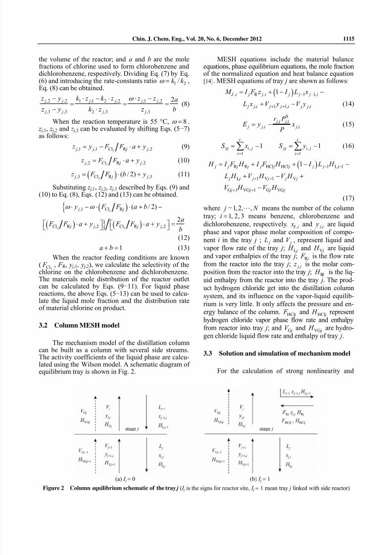
and the separation temperature in benzene chlorination process, the SCR integrated structure for chloroben-zene production is designed, and the dynamic controlsystem is researched. The configuration of SRC forchlorobenzene production is shown in Fig. 1. In Fig. 1,the lighter component benzene moves toward the col-umn top and the heavier component chlorobenzene and
dichlorobenzene move to the column bottom, in whichthere are two different zones: reaction zone and sepa-ration zone. The several trays in the reaction zone arelinked with three side reactors, respectively. The con-tinuous chlorine with a certain proportion is introduced
to the bottom of three reactors, respectively, while fresh benzene is given to the first reactor connected with thetop condenser. The hydrogen chloride generated in thereactions will escape from the condenser of the column.With continuous removal of the desired product chloro- benzene from the reaction zone, a higher selectivity may be achieved.
3 MODELING AND SIMULATING
The SRC process mechanism model contains two parts: MESH equations of the column and chemicalkinetic model equations.
3.1 Reaction mechanism model
Each reactor was assumed to be a perfectly adia- batic mixed stirred tank reactor, and in the continuouschlorination reaction system continuous reaction ma-terial equilibrium equations with the tray j are as fol-lows Eqs. (5)-(13):
( )2,1 ,1 R 1 ,1 Cl ( / 2) j j j j y z F V k z F a b− ⋅ = ⋅ ⋅ = ⋅ + (5)
( ) ( )2,2 ,2 R 1 ,1 2 ,2 Cl j j j j j z y F V k z k z F a− ⋅ = ⋅ ⋅ − ⋅ = ⋅ (6)
( ) 2,3 ,3 R 2 ,3 Cl / 2 j j j j z y F V k z F b− ⋅ = ⋅ ⋅ = ⋅ (7)
where y j,1, y j,2, y j,3, z j,1, z j,2 and z j,3 are the inlet andoutlet mole compositions of benzene, chlorobenzeneand dichlorobenzene from the reactor which is con-nected with the j-th tray; F R j is the inlet liquid flowrate to the reactor;
2Cl F is chlorine feed flow rate; V is
Figure 1 Configuration of the SRC process for chlorobenzene production
7/27/2019 20120612 - poços de caldas
http://slidepdf.com/reader/full/20120612-pocos-de-caldas 3/8
Chin. J. Chem. Eng., Vol. 20, No. 6, December 2012 1115
the volume of the reactor; and a and b are the molefractions of chlorine used to form chlorobenzene anddichlorobenzene, respectively. Dividing Eq. (7) by Eq.(6) and introducing the rate-constants ratio 1 2/k k ω = ,Eq. (8) can be obtained.
,2 ,2 1 ,1 2 ,2 ,1 ,2
,3 ,3 2 ,3 ,3
2 j j j j j j
j j j j
z y k z k z z z a
z y k z z b
ω − ⋅ − ⋅ ⋅ −= = =− ⋅
(8)
When the reaction temperature is 55 °C, 8ω = . z j,1, z j,2 and z j,3 can be evaluated by shifting Eqs. (5-7)as follows:
2,1 ,1 Cl R ,2 j j j j z y F F a y= − ⋅ + (9)
2,2 Cl R ,2 j j j z F F a y= ⋅ + (10)
( )2,3 Cl R ,3( / 2) j j j z F F b y= ⋅ + (11)
Substituting z j,1, z j,2, z j,3 described by Eqs. (9) and
(10) to Eq. (8), Eqs. (12) and (13) can be obtained.
( ){
( ) } ( )
2
2 2
,1 Cl R
Cl R ,2 Cl R ,2
( / 2)
2
j j
j j j j
y F F a b
a F F a y F F a y
b
ω ω ⋅ − ⋅ ⋅ + −
⋅ + ⋅ + =⎡ ⎤ ⎡ ⎤⎣ ⎦ ⎣ ⎦
(12)
1a b+ = (13)
When the reactor feeding conditions are known(
2Cl F , F R , y j,1, y j,2), we calculate the selectivity of thechlorine on the chlorobenzene and dichlorobenzene.The materials mole distribution of the reactor outletcan be calculated by Eqs. (9-11). For liquid phase
reactions, the above Eqs. (5-13) can be used to calcu-late the liquid mole fraction and the distribution rateof material chlorine on product.
3.2 Column MESH model
The mechanism model of the distillation columncan be built as a column with several side streams.The activity coefficients of the liquid phase are calcu-lated using the Wilson model. A schematic diagram ofequilibrium tray is shown in Fig. 2.
MESH equations include the material balanceequations, phase equilibrium equations, the mole fractionof the normalized equation and heat balance equation[14]. MESH equations of tray j are shown as follows:
( ), R , 1 1,
, 1 1, ,
1i j j i j j j i
j j i j j i j j i
M I F z I L x
L x V y V y
− −
+ +
= + − −
+ − (14)
S, ,
, ,
j i j i
j j i j i
r P E y x
P = − (15)
,
1
1c
xj i j
i
S x=
= −∑ ,
1
1c
yj i j
i
S y=
= −∑ (16)
( )R R HCl HCl 1 L 1
L 1 V 1 V
G 1 VG 1 G VG
1 j j j j j j j j j j
j j j j j j
j j j j
H I F H I F H I L H
L H V H V H
V H V H
− −
+ +
+ +
= + + − −
+ − +
−
(17)
where 1,2, , j N = means the number of the column
tray; 1, 2, 3i = means benzene, chlorobenzene and
dichlorobenzene, respectively. ,i x and , j i y are liquid
phase and vapor phase molar composition of compo-
nent i in the tray j ; j L and jV , represent liquid and
vapor flow rate of the tray j; L j H and V j H are liquid
and vapor enthalpies of the tray j; R j F is the flow rate
from the reactor into the tray j; , j i z is the molar com-
position from the reactor into the tray j; R H is the liq-
uid enthalpy from the reactor into the tray j. The prod-
uct hydrogen chloride get into the distillation column
system, and its influence on the vapor-liquid equilib-
rium is very little. It only affects the pressure and en-
ergy balance of the column. HCl j F and HCl j H represent
hydrogen chloride vapor phase flow rate and enthalpy
from reactor into tray j; and G jV and VG j H are hydro-
gen chloride liquid flow rate and enthalpy of tray j.
3.3 Solution and simulation of mechanism model
For the calculation of strong nonlinearity and
(a) I j = 0 (b) I j = 1
Figure 2 Column equilibrium schematic of the tray j ( I j is the signs for reactor site, I j = 1 mean tray j linked with side reactor)
7/27/2019 20120612 - poços de caldas
http://slidepdf.com/reader/full/20120612-pocos-de-caldas 4/8
Chin. J. Chem. Eng., Vol. 20, No. 6, December 2012 1116
coupled relation between thermodynamic equilibriumand the kinetic equations of non-ideal system, the so-lution of mechanism model is more complex. Sincethe simulating convergence of model is rather difficult,a good initial value to ensure reliable convergence is
needed. In this paper, it is firstly assumed that the ca- pacity of the reactor is large enough to promise chlo-rine to be consumed completely, and the feeding flowrates of chlorine (
2Cl F ) are defined as the independentreaction amount. Therefore, the mechanism model may be equivalent to distillation column simulation problemwith multi-stream inlet and outlet. After distillationcolumn calculating convergent, the material propertiesof the reactor can be obtained, which is connectedwith the tray j. According to reaction kinetics model,the sizes of reactors are calculated. This solution hasgreatly improved the convergence speed of the modelof the SCR process [15]
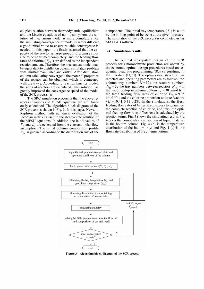
The SRC simulation process is that the above re-
actors equations and MESH equations are simultane-ously calculated. The algorithm block diagram of theSCR process is shown in Fig. 3. In this paper, Newton-Raphson method with numerical evaluation of theJacobian matrix is used to the steady-state solution ofthe MESH equations. In addition, the initial values of
jV and j L are generated from the constant molar flowassumption. The initial column composition profile
, j i x is guessed according to the distribution rule of the
components. The initial tray temperature ( jT ) is set to be the boiling point of benzene at the given pressure.The simulation of the SRC process is completed usingMATLAB software.
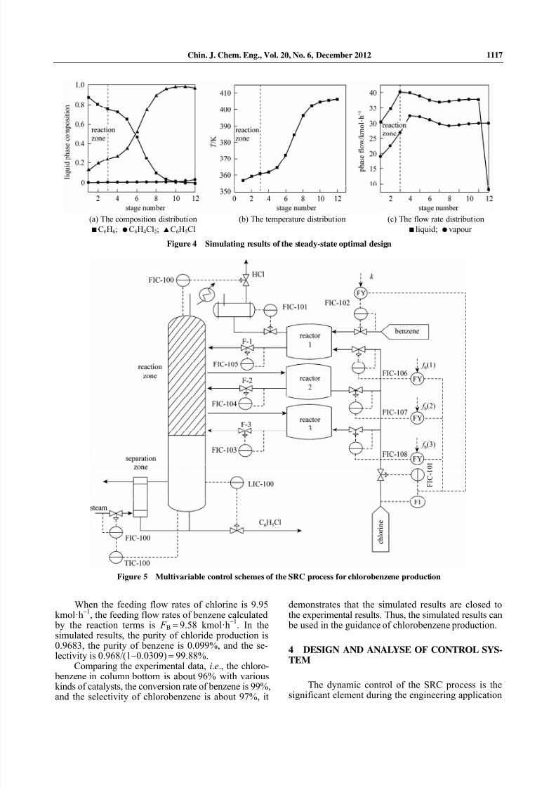
3.4 Simulation results
The optimal steady-state design of the SCR process for Chlorobenzene production are obtain bythe economic optimal design procedures based on se-quential quadratic programming (SQP) algorithmic inthe literature [15, 16]. The optimization structural pa-rameters and operating parameters are as follows: thecolumn tray numbers 12 N = ; the reactors numbers
R 3 N = ; the tray numbers between reactors RS 1 N = ;the vapor boilup in column bottom 30nV = kmol·h
−1;
the fresh feeding flow rates of chlorine2Cl F = 9.95
kmol·h−1
; and the chlorine proportion to three reactors
f b(i) = [0.41 0.31 0.28]. In the simulations, the freshfeeding flow rates of benzene are excess to guaranteethe complete reaction of chlorine, and thus, the opti-mal feeding flow rates of benzene is calculated by thereaction terms. Fig. 4 shows the simulating results. Fig.4 (a) is the composition distribution of liquid materialin the bottom column, Fig. 4 (b) is the temperaturedistribution of the bottom tray; and Fig. 4 (c) is theflow rate distribution of the column bottom.
Figure 3 Algorithm block diagram of the SCR process
7/27/2019 20120612 - poços de caldas
http://slidepdf.com/reader/full/20120612-pocos-de-caldas 5/8
Chin. J. Chem. Eng., Vol. 20, No. 6, December 2012 1117
When the feeding flow rates of chlorine is 9.95kmol·h
−1, the feeding flow rates of benzene calculated
by the reaction terms is F B = 9.58 kmol·h−1
. In thesimulated results, the purity of chloride production is0.9683, the purity of benzene is 0.099%, and the se-lectivity is 0.968/(1−0.0309) = 99.88%.
Comparing the experimental data, i.e., the chloro- benzene in column bottom is about 96% with various
kinds of catalysts, the conversion rate of benzene is 99%,and the selectivity of chlorobenzene is about 97%, it
demonstrates that the simulated results are closed tothe experimental results. Thus, the simulated results can be used in the guidance of chlorobenzene production.
4 DESIGN AND ANALYSE OF CONTROL SYS-TEM
The dynamic control of the SRC process is thesignificant element during the engineering application
(a) The composition distribution (b) The temperature distribution (c) The flow rate distribution ■ C6H6; ● C6H4Cl2; ▲ C6H5Cl ■ liquid; ● vapour
Figure 4 Simulating results of the steady-state optimal design
Figure 5 Multivariable control schemes of the SRC process for chlorobenzene production
7/27/2019 20120612 - poços de caldas
http://slidepdf.com/reader/full/20120612-pocos-de-caldas 6/8
Chin. J. Chem. Eng., Vol. 20, No. 6, December 2012 1118
design of integrated technology [17]. Comparing withthe conventional distillation, the dynamic characteristicsof the SRC process are more complicated. As a resultof the interaction between the reaction and the separa-tion, the SRC process has strong nonlinear, coupling
and multi steady-stable characteristics [18]. The abovecharacteristics make the dynamic operation and con-trol for the SRC process become bottleneck problems.
4.1 Design of multivariable control schemes
Based on the above economic optimal design andsimulation analysis of the SRC process for chloro- benzene production, the multivariable control schemesare developed with the conventional control strategiesas shown in Fig. 5.
The control schemes include several control loops,such as the liquid level control loops (LIC-100, LIC-101),
the pressure control loop (PIC-100), the feed flow ratecontrol loops (FIC-101, FIC-102), outlet flow ratescontrol loops of the three reactors (FIC-103, FIC104,FIC105), the temperature cascade control loop (TIC-100),etc., which are given in Table 2. For the compositionanalyzers have higher cost, require more maintenance,and can introduce dead-time into the control loop, thetemperature cascade control loop is proposed. Thetemperature control of column bottom is the main loop(TIC-100), and the control of the steam flow rate issub-loop (FIC-100), which are shown in Fig. 5.
4.2 The performance analysis of the close-loop
control system
The dynamic simulation of the SRC process forchlorobenzene production with the above designed con-trol structures are explored with chemical simulationsoftware HYSYS. Through reasonable setting controlsystem parameters and operating parameters, theclosed loop control system of the SRC process can runsmooth and attain the expected control goals. To check
the effectiveness of this control structure, the distur- bances of feed flow rates, the feed composition andthe steam calorific value disturbances are applied tothe system, respectively.
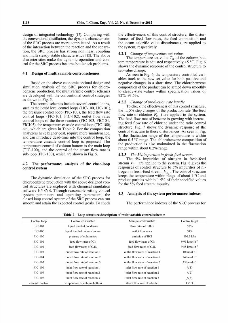
4.2.1 Change of temperature set-value The temperature set-value T sp of the column bot-
tom temperature is adjusted respectively ±5 °C. Fig. 6shows the dynamic response of the control structure toset-value change.
As seen in Fig. 6, the temperature controlled vari-ables track to the new set-value for both positive andnegative changes in a short time. The chlorobenzenecomposition of the product can be settled down smoothlyto steady-state values within specification values of92%-93.5%.
4.2.2 Change of production rate handle To check the effectiveness of this control structure,
the ±5% step changes of the production rate (the feedflow rate of chlorine
2Cl F ) are applied to the system.The feed flow rate of benzene is growing with increas-ing feed flow rate of chlorine under the ratio controlstructure. Fig. 7 shows the dynamic response of thecontrol structure to these disturbances. As seen in Fig.7, the fluctuation range of the temperature is withinabout 0.5 °C range. The chlorobenzene composition ofthe production is also maintained in the fluctuationrange within about 0.2% range.
4.2.3 The 5% impurities in fresh-feed stream The 5% impurities of nitrogen in fresh-feed
stream2Cl F are applied to the system. Fig. 8 gives the
responses of control structure to 5% impurities of ni-trogen in fresh-feed stream
2Cl F . The control structurekeeps the temperature within range of about 1 °C and product purities within 1.5% of their specified valuesfor the 5% feed stream impurity.
4.3 Analysis of the system performance indexes
The performance indexes of the SRC process for
Table 2 Loop structure description of multivariable control schemes
Control loop Controlled variable Manipulated variable Control target
LIC-101 liquid level of condenser flow rates of reflux 50%
LIC-100 liquid level of column bottom outlet flow rates 50%
PIC-100 pressure of column top emission of HCl 101.3 kPa
FIC-101 feed flow rates of Cl2 feed flow rates of Cl2 9.95 kmol·h−1
FIC-102 feed flow rates of C6H6 feed flow rates of C6H6 9.58 kmol·h−1
FIC-103 outlet flow rate of reaction 1 outlet flow rates of reaction 1 10 kmol·h−1
FIC-104 outlet flow rate of reaction 2 outlet flow rates of reaction 2 24 kmol·h−1
FIC-105 outlet flow rate of reaction 3 outlet flow rates of reaction 3 25 kmol·h−1
FIC-106 inlet flow rate of reaction 1 inlet flow rate of reaction 1 f b(1)
FIC-107 inlet flow rate of reaction 2 inlet flow rate of reaction 2 f b(2)
FIC-108 inlet flow rate of reaction 3 inlet flow rate of reaction 3 f b(3)
cascade control temperature of column bottom steam flow rate of reboiler 135 °C
7/27/2019 20120612 - poços de caldas
http://slidepdf.com/reader/full/20120612-pocos-de-caldas 7/8
Chin. J. Chem. Eng., Vol. 20, No. 6, December 2012 1119
chlorobenzene production, such as the settling time t s,the absolutely integral error IAE and the steady-state
error e(∞
) are calculated further under the above dis-turbances conditions. The calculating results are given
in Table 2. Through the analysis of the performanceindexes of the control system in Table 3, the recom-
mended multivariate control structure can overcomeeffectively the above different type disturbances within
(a) (b)
Figure 6 Dynamic response under the temperature set value T sp changesT sp + 5 °C; T sp − 5 °C
(a) (b)
Figure 7 Dynamic response under step change (±5%) in production rate handleflow 5%+ ; flow 5%−
(a) (b)
Figure 8 The dynamic response under the 5% impurities in fresh-feed stream
Table 3 Analysis of the system performance indexes
Temperature response Composition responseDisturbance
Disturbance
amplitude t s/min IAE e(∞) t s/min IAE e(∞)
T sp change +5℃ 30 76.42 0.5 30 0.04 0.001
−5℃ 75 183.66 0.3 75 0.06 0.002
production rate handle2Cl F Δ +5% 3.4 0.22 0.5 3.4 0.001 0.002
−5% 3.4 0.28 0.3 3.4 0.001 0.002
5% impurities in feed stream2Cl F 5% 2.87 43 0.12 2.87 1.22 0.015
7/27/2019 20120612 - poços de caldas
http://slidepdf.com/reader/full/20120612-pocos-de-caldas 8/8
Chin. J. Chem. Eng., Vol. 20, No. 6, December 2012 1120
a certain range.
5 CONCLUSIONS
The distillation column with side reactors can notonly effectively increase the conversion and selectivity, but also can overcome the temperature or pressuremismatch in the traditional reactive distillation. In this paper, the mechanism model, the optimizing designand dynamic control of the SRC process for chloro- benzene production are discussed. The effectivenessof control structure is demonstrated using disturbancesin production rate and fresh-feed compositions.
The simulating results show that the control struc-ture using conventional control strategies can effectivelyovercome various disturbances in a specific range.However, owing to the nonlinear and coupling char-acteristics, the system will probably deviate from the
ideal condition and even cause the instability when thedisturbance with larger range is added. The dynamicintelligent control methods and the multivariate pre-dictive control will be researched in future work tosolve the problems about the on-line optimizing op-eration and synergy control for the SRC process.
NOMENCLATURE
2Cl F chlorine feeding flow rate, kmol·h−1
F R j inlet liquid flow rate of reactor, kmol·h−1
f b distributed ratio of chlorine to reactor
H L j liquid enthalpies of tray j, MJ·kmol−1
H R j liquid enthalpy from the reactor into tray j, MJ·kmol−1
H V j vapor enthalpies of tray j, MJ·kmol−1
i number of components
j number of trays
k reaction rate constant, h−1
L j liquid flow rate of tray j, kmol·h−1
N number of trays in the column
N R number of the side reactors
N RS number of trays between adjacent reactors in the reaction zone
N S number of stripping trays
r reaction rate, kmol·L−1
·h−1
T j column temperature on tray j, K
V j vapor flow rate of tray j, kmol·h−1
x j,i mole compositions of component i in liquid on tray j
y j,c inlet mole compositions of reactor, kmol·L−1
y j,i mole compositions of component i in vapor on tray j
z j,c outlet mole compositions of reactor, kmol·L−1
ω rate-constants ratio
REFERENCES
1 Harwardt, A., Kraemer, K., Rüngeler, B., “Conceptual design of a
butyl-levulinate reactive distillation process by incremental refine-
ment”, Chin. J . Chem. Eng ., 19 (3), 371-379 (2011).
2 Kaymak, D.B., Luyben, W.L., “Optimum design of a column/side
reactor process”, Ind . Eng . Chem. Res., 46, 5175-5185 (2007).
3 Sundmacher, K., Kienle, A., “Reactive distillation: status and future
directions”, Wiley-VCH, Weiheim, Germany (2003).
4 Kaymak, D.B., Luyben, W.L., “Design of distillation columns with
external side reactors”, Ind . Eng . Chem. Res., 43 (25), 8049-8056
( 2004).
5 Baur, R., Krishna, R., “Distillation column with reactive pump
arounds: an alternative to reactive distillation”, Chem. Eng . and
Process., 43 (3), 435-445 (2004).
6 Radulescu, G., Gangadwala, J., Paraschiv,N., “Dynamics of reactive
distillation processes with potential liquid phase splitting based on
equilibrium stage models”, Computers and Chemical Engineering ,
33 (3), 590-597 (2009).
7 Al-Arfaj, M.A., Luyben, W.L., “Comparison of alternative control
structures for an ideal two-product reactive distillation column”, Ind .
Eng . Chem. Res., 39 (9), 3298-3307 (2000).
8 Al-Arfaj, M.A., Luyben, W.L., “Comparative control study of ideal
and methy acetate reactive distillation”, Chem. Eng . Sci., 57 (24),
5039-5050 (2002).
9 Kaymak, D.B., Luyben, W.L., “Comparison of two types of
two-temperature control structures for reactive distillation columns”,
Ind . Eng . Chem. Res., 44 (13), 4625-4640 (2005).
10 Wang, S.J., Yu, C.C., Huang, H.P, “Plant-wide design and control of
DMC synthesis process via reactive distillation and thermally cou-
pled extractive distillation”, Computers and Chemical Engineering ,
34 (3), 361-373 (2010).
11 Kaymak, D.B, Luyben, W.L., “Dynamic control of a column/side-
reactor process”, Ind . Eng . Chem. Res., 47 (22), 8704-8712 (2008).
12 Tsai, R.C., Cheng, J.K., Huang, H.P., Yu, C.C., “Design and control
of the side reactor configuration for production of ethyl acetate”, Ind .
Eng . Chem. Res. , 47 (23), 9472-9484 (2008).
13 Cui, M.F. Huang, X.Z., Qiao, X., “Study on process of chlorination
of benzene in the three-phase catalytic-distillation column with va- por diffluence”, Journal of Chemical Engineering of Chinese Uni-
versities, 18 (6), 696-700 (2004).
14 Ye, J.C., Huang, J.C., Lin, H., “Kinetic-thermodynamic analysis of
the reactive distillation process of the cyclohexene hydration using
the zeolite catalyst”, Chin. J . Chem. Eng ., 19 (5), 808-814 (2011).
15 Ding, L.H., Tang, J.H., Cui, M.F., Bo, C.M., Qiao, X., “Optimum
design and analysis based on independent reaction amount for distil-
lation column with side reactors: production of benzyl chloride”, Ind .
Eng . Chem. Res., 50 (19), 1143-1152 (2011).
16 Bo, C.M., Tang, J.H., Qiao, X., Ding, L.H., Cui, M.F., “The optimi-
zation method and simulating system of distillation column with side
reactors for benzene chloride production”, Journal of Shanghai
Jiaotong University, 45 (8), 1157-1162 (2011). (in Chinese)
17 Suresh Babu, K., Pavan Kumar, M.V., Kaistha, Nitin, “Controllable
optimized designs of an ideal reactive distillation system using ge-
netic algorithm”, Chem. Eng . Sci, 64, 4929-4942 (2009).18 Lin, Y.D., Huang, H.P., Yu, C.C., “Relay feedback tests for highly
nonlinear processes: reactive distillation”, Ind . Eng . Chem. Res., 45
(12), 4081-4092 (2006).