Embed Size (px)
Citation preview

8/11/2019 D550 Extreme Manual Eng
http://slidepdf.com/reader/full/d550-extreme-manual-eng 1/42 1
SHAFT
ALIGNMENT
SYSTEM
MANUALEnglish

8/11/2019 D550 Extreme Manual Eng
http://slidepdf.com/reader/full/d550-extreme-manual-eng 2/42 2
8/11/2019 D550 Extreme Manual Eng
http://slidepdf.com/reader/full/d550-extreme-manual-eng 3/42
8/11/2019 D550 Extreme Manual Eng
http://slidepdf.com/reader/full/d550-extreme-manual-eng 4/42

8/11/2019 D550 Extreme Manual Eng
http://slidepdf.com/reader/full/d550-extreme-manual-eng 5/42 a1
sysTeM
Complete system (Part No:12-0340). Includes:
1 Display unit (Part No:12-0336)
1 Measuring unit M (Part No:12-0334)
1 Measuring unit S (Part No:12-0335)
2 Shaft brackets with chains (Part No:12-0337)
2 Extension chains (Part No:12-0363)*
8 Rods 120 mm (Part No:01-0873)*1 Hexagon key for battery lid (Part No:03-0699)*
1 Rod tightening tool (Part No:01-0048)
3 Cables with push-pull connectors, 2 m (Part No:12-0074)
1 Cable with push-pull connectors, 5 m (Part No:12-0108)
1 Measuring tape (Part No:12-0012)
1 Manual
1 EasyLink™ PC program
1 Carrying case (Part No:12-0339)
1 USB adaptor (Part No:03-0722)
1 Null modem cable (Part No:03-0333)
*Located in the tool pocket
caRRying case
TecHnical sPecificaTions
Measuring distance 20 m
Ambient temperature 0–40 °C
Weight total in case 7.3 kg
Ruggedized, intrinsically safe, IP66/IP67 protected shaft alignment system.
Aluminum case with conductive contoured foam pad-
ding. Approved for Ex environments.
TecHnical sPecificaTions
Weight 3 kg
Dimensions 490x350x200 mm

8/11/2019 D550 Extreme Manual Eng
http://slidepdf.com/reader/full/d550-extreme-manual-eng 6/42 a2
MeasURing UniTs
bRackeTs
Bracket with pre-mounted chain, locking frame and
spare locking screw which also functions as a stopper
for the frame.
Measuring units with PSD detector (20x20 mm),
electronic 360° inclinometer and laser diode in one
housing.
Delivered as a pair with S-unit and M-unit (for Station-
ary and Movable machine).
Measurement values when moved according to arrows.
TecHnical sPecificaTions
Detector type 2-axis PSD
Detector size 20x20 mm
Linearity Better than 1%
Laser diode < 1 mW Class 2
Laser wavelength 635-670 nm
Inclinometer resolution 0.1°
Thermal sensor resolution 0.1°
Dimensions 75x65x52 mm
Housing material Hard anodized aluminum
Weight 220 g
Water and dust protected IP66 / IP67
TecHnical sPecificaTions
Shaft diameter 20-450 mm, extension chain for larger diameters
Material Stainless steel, including the chain
Weight 800 g
Labels on measuring units S
and M respectively (top).
Label on measuring units (back side) 1.
Label on measuring units (back side) 2.
MV+
MH+ SH+
SV+
R+ R+
(Marking labels consist of polyester)
Connectors Detector (PSD) aperture Laser aperture
Adjustment screw (near the PSD for Vertical adj.)
Adjustment screw (near the
Laser for Horizontal adj.)
Adjustment screws (Appr. ±3 revolutions = ±3° angular adj.)
Locking screw
Spare screw
8/11/2019 D550 Extreme Manual Eng
http://slidepdf.com/reader/full/d550-extreme-manual-eng 7/42 a3
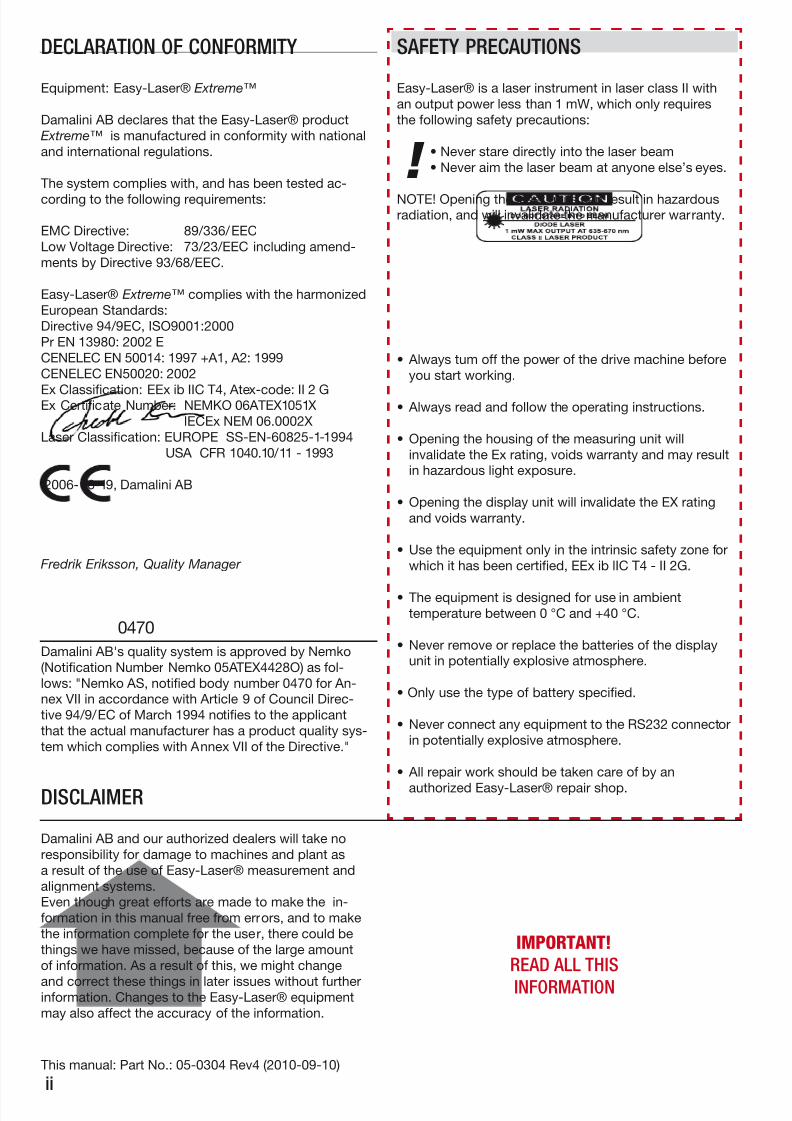
DisPlay UniT
TecHnical sPecificaTions
Housing material Anodized aluminum / Chrome plated aluminum
Keyboard 16 membrane buttons
Display 4.5” LCD
Battery type Duracell Procell Alkaline Mn1400 (PC1400)LR14 1.5 VOperating time 20 hrs continuously
Displayed resolution Changeable, down to 0.001 mm (0.05 mil)
Memory Stores up to 1000 measurements
External connector RS232, 9P PC or printer
Dimensions 183x155x45 mm
Weight 1000 g
Water and dust protected IP66 / IP67
Battery operated unit.
Membrane keyboard with 16 buttons.
Measurement data storage.
Serial port for printer and PC communication.
Note: Do not connect the serial port in a potentially
explosive atmosphere.
Back side label of display unit. (Marking label consists of polyester)
Replacing batteries. When batteries are low (see B1,battery condition), the batteries need to be replaced.
Follow this procedure when replacing the batteries:
1. Do not remove batteries in a potentially explosive
atmosphere.
2. Only use batteries Duracell Procell Alkaline Mn1400
(PC1400) LR14 1.5 Volt
3. Press and hold the lid close to the unit, then use the
hexagon key from the tool pocket and unscrew the two
screws about 4 mm. Release the lid.
4. When closing, press the lid to completely compress
the springs, then tighten the two screws.
How to connect the units.

8/11/2019 D550 Extreme Manual Eng
http://slidepdf.com/reader/full/d550-extreme-manual-eng 8/42 a4

8/11/2019 D550 Extreme Manual Eng
http://slidepdf.com/reader/full/d550-extreme-manual-eng 9/42 b1
aUTo off fUncTions / PRogRaM MenU / loss of signal
The menu for main settings, print and store is shown
when pressing . This can of course be done during
measurement. When the display unit is shut off, all
the settings will remain (except measurement filter
value and tolerance checked display of measurement
result). Press corresponding numeric key to change or
execute settings. Only available choices are shown.
Each touch changes the Contrast of the display to
one of ten steps.
Set the current Date in the system clock. Set the current Time in the system clock.
Set the time until Auto-Off between 10 and 99
minutes. 00 disables Auto-Off.
Set Measurement Filter Value between 0 and 30.
(see page B4)
Toggle the units of measurement between 0.1,
0.01, 0.001 mm: 5, 0.5, 0.05 mils: 5, 0.5, 0.05 thou.
Print the previous screen on a connected printer.
Send the measurement result to a connected
printer or PC.
Store and Restore measurement results.
Help: Shows available program choices at each
step of the measurement program procedure.
Return.
Shows the number of
measuring units con-
nected.
Number of measure-
ments stored.
Battery condition is
shown as a series of *,Max. at H and Min. at L.
Main MenU
During power-up, the program version is shown for
about 2 seconds.
Then the measurement program menu is shown. Start
a program by entering the appropriate number.
When a program is running, pressing will exit the
program and return to Program menu.
Pressing in the Program menu will turn the
Display unit off.
If no program is started, the Display unit will be
turned off after 10 minutes.
When a program is running, but no buttons are
pressed, the Display unit will return to the Program
menu when the Auto Off Time expires (see B1).
No signal
Current measurement values becomes +++++
when loss of signal, for example if the laserbeam is
interrupted.
When connection failure, for example if cable isn’tconnected, measurement values become --------
Program version
Loss of signal from the M unit
Included measurement programs
8/11/2019 D550 Extreme Manual Eng
http://slidepdf.com/reader/full/d550-extreme-manual-eng 10/42 b2
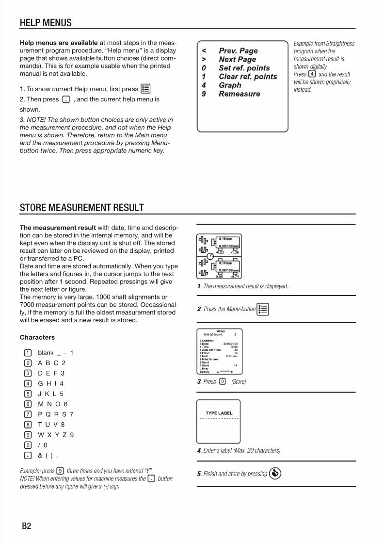
sToRe MeasUReMenT ResUlT
The measurement result with date, time and descrip-
tion can be stored in the internal memory, and will be
kept even when the display unit is shut off. The stored
result can later on be reviewed on the display, printed
or transferred to a PC.
Date and time are stored automatically. When you type
the letters and figures in, the cursor jumps to the next
position after 1 second. Repeated pressings will give
the next letter or figure.
The memory is very large. 1000 shaft alignments or
7000 measurement points can be stored. Occassional-
ly, if the memory is full the oldest measurement stored
will be erased and a new result is stored.
1. The measurement result is displayed...
3 . Press (Store)
4 . Enter a label (Max. 20 characters).
Characters
blank _ - 1
A B C 2
D E F 3
G H I 4
J K L 5
M N O 6
P Q R S 7
T U V 8
W X Y Z 9
/ 0
& ( ) .
Example: press three times and you have entered “Y”.
NOTE! When entering values for machine measures the buttonpressed before any gure will give a (-) sign.
2 . Press the Menu-button
5 . Finish and store by pressing
HelP MenUs
Help menus are available at most steps in the meas-
urement program procedure. “Help menu” is a display
page that shows available button choices (direct com-
mands). This is for example usable when the printed
manual is not available.
1. To show current Help menu, first press
2. Then press , and the current help menu is
shown.
3. NOTE! The shown button choices are only active in
the measurement procedure, and not when the Help
menu is shown. Therefore, return to the Main menu
and the measurement procedure by pressing Menu-
button twice. Then press appropriate numeric key.
Example from Straightness
program when the
measurement result is
shown digitally.
Press and the result
will be shown graphically
instead.

8/11/2019 D550 Extreme Manual Eng
http://slidepdf.com/reader/full/d550-extreme-manual-eng 11/42 b3
ResToRe anD DeleTe MeasUReMenTs
Restore a measurement by turning the system on
and then press the Menu-button before starting any
program. Choose Restore and each stored measure-
ment is displayed with Date, Time and Label. The
measurements are sorted in chronological order with
the latest at the first position (number 1). Up to five
measurements can be displayed at each time. Enter
the corresponding number for the measurement tobe restored or deleted, then select desired function.
When the data is displayed it can be printed or trans-
ferred to a PC. This is done as usual via the Main menu
by pressing Print or Send .
Press to conrm deletion of all stored measurements.
[Return to list ]
1. Start the system
2 . Press Menu-button
3 . Press (Restore)
4 . Press corresponding gure to display desired measurement.
[Toggle between pages with ]
Number of stored measurements.
Page number and totalamount of pages.
Your label
5 . Select desired function:
Restore measurement
Delete this measurement
Delete all stored measurements
Back
The measurement result is displayed.[Return to list by pressing ]
Press to conrm deletion of this measurement.
[Return to list ]
Program used Time when stored

8/11/2019 D550 Extreme Manual Eng
http://slidepdf.com/reader/full/d550-extreme-manual-eng 12/42 b4
PRinT anD senD MeasUReMenT
Easy-Laser® is equipped with an RS 232 C, 9 pin D-sub connector for
printer or PC. The printer must be Epson compatible to achieve a propergraphic printout. Port settings: 9600 Baud, no parity check, 8 data bits,1
stopbit. For USB connection, use the RS232/USB adaptor.
Two options are available for measurement data
transfers. These are carried out from the Main menu.
The Print Screen command transfers a copy of what is
shown on the display. Actually a screen-dump.
The Send command transfers a complete set of infor-
mation, in text mode. Transferring a previously stored
measurement also includes description if available.
When using the programs Offset and Angle and Val-ues, measurement values can be sent directly from the
detector to the serial port. The EasyLink™ software
(or other similar terminal program) can recieve the data
sent. (For installation of EasyLink™, see page D6.)
1. Press
2 . Press (print) or (send)
Example: printout from Straightness-program.
Print Screen performs a graphic
screen dump.
Send transfers a complete set
of information about current
measurement in text mode.
The serial number of the
equipment used and the
measurement temperature
will also be specied.
MeasUReMenT ValUe filTeR
If the laser beam passes through air with varying
temperature, this may influence the direction of the la-
ser beam. If measurement values fluctuate, this could
mean unstable readings. Try to reduce air movements
between laser and detector by, for instance, moving
heat sources, closing doors etc. If the readings remain
unstable, increase the filter time (more samples will
become available to the statistical filter). In the Main
menu, choose a filter value between 1 and 30. Use as
short a time as possible that still produces acceptable
stability during the measurement.
Filter value 0=filter not active.
Note! Settings for filter value are not saved when the
Display unit is turned off.
Always ensure a good measurement environment.
3 . Press (lter).
4 . Select suitable value.
5 . Press to return to measurement.
When measurement values are registering, “WAIT 5” is displayed,
where the number corresponds to chosen lter value and counts
down to 0. NOTE! Do not interrupt the laserbeam or move the detector
before countdown is complete.
1. Unstable values...
2 . Press
8/11/2019 D550 Extreme Manual Eng
http://slidepdf.com/reader/full/d550-extreme-manual-eng 13/42 b5
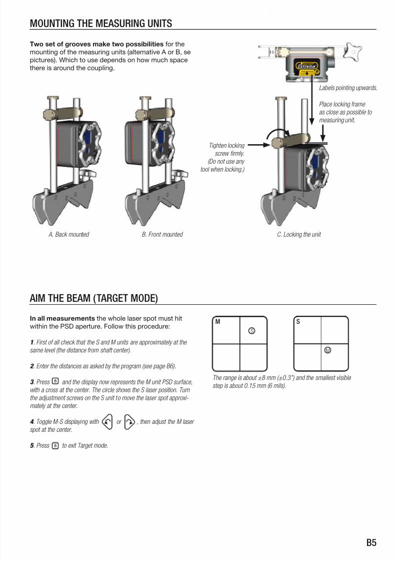
MoUnTing THe MeasURing UniTs
Two set of grooves make two possibilities for the
mounting of the measuring units (alternative A or B, se
pictures). Which to use depends on how much space
there is around the coupling.
A. Back mounted B. Front mounted
Complies with21 CFR1040.10 and1040.11EEx ibIIC T4 Nemko 05ATEX100X
AVOID EXPOSURE
Laserlight is emitted
fromthis aperture II2GS
Labels pointing upwards.
Place locking frame
as close as possible to
measuring unit.
Tighten locking
screw rmly.
(Do not use any
tool when locking.)
C. Locking the unit
aiM THe beaM (TaRgeT MoDe)
In all measurements the whole laser spot must hit
within the PSD aperture. Follow this procedure:
1. First of all check that the S and M units are approximately at the
same level (the distance from shaft center).
2 . Enter the distances as asked by the program (see page B6).
3 . Press and the display now represents the M unit PSD surface,
with a cross at the center. The circle shows the S laser position. Turnthe adjustment screws on the S unit to move the laser spot approxi-
mately at the center.
4 . Toggle M-S displaying with or , then adjust the M laser
spot at the center.
5 . Press to exit Target mode.
M
S
s
M
The range is about ±8 mm (±0.3”) and the smallest visible
step is about 0.15 mm (6 mils).

8/11/2019 D550 Extreme Manual Eng
http://slidepdf.com/reader/full/d550-extreme-manual-eng 14/42 b6
RoUgH alignMenT
enTeRing THe DisTances (HoRiZonTal sHafT alignMenT)
When you select a shaft alignment program the sys-
tem asks for the distances between measuring units,
coupling and feet. Enter the distances according to
the pictures below. The system can handle distances
between 1 and 32000 mm (1260 Inch).
When turning the shafts with measuring units
mounted, the laserbeams will project arcs, where the
centres will coincide with the centres of the shafts.
During the turning the laser beams will move on the
detector surfaces. When the alignment is poor the
beams may travel outside the detectors. If this hap-
pens you will have to do a rough alignment first.
Preparation: mount the equipment.
Enter the distances as asked by the system, then press .
1. Turn shafts with measuring units to the 9 o’clock position. Adjust
the laserbeams to the centre of the PSDs.
2 . Turn shafts with measuring units to the 3 o’clock position.
3 . Check where the laser hits, then adjust the beams half the travel in
direction to the centre of the PSDs (see picture below).
[Toggle S-M unit displaying with ]
4 . Adjust/move the movable machine so that the laser beam hits the
centres of both the PSDs. Done.
2 . The laser hits outside
the PSD.
The arc described by the laserbeam from the M-unit during turning.
(Only S-unit shown, faced from the M-unit)
S –M =distance between measuring units.
S –F1=distance between stationary detector (S) and feetpair 1 (F1).
(To enter a negative [S-F1] value, rst press for minus sign, then
enter the value.)
S –C =distance between S and Center of coupling (if the coupling is
in the middle between the measuring units, just press “Enter”. If not,
enter the right value).S –F2 =distance between S and F2 (must be longer than S-F1).
[S –F2] =if the machine has three pairs of feet, you can add this dis-
tance after nished measurement, and let the system calculate a new
shimming and adjustment value for this pair of feet (see page C2).
Type the distances in by using the numerical keys.
Conrm each distance with
[ Redo with ]
s–M
s–c
s–f1
s–f2[s–f2]
s
M
S unit PSD centre
M unit laser beam
Position 9
PosiTion 3PosiTion 9
43
2
s
Position 3
sM
Position 3
3 . Adjust half the travel
with the adjustmentscrews on the M unit.
s
M
Position 3
4 . Adjust/move the mov-
able machine so that thelasers hit the centres.
1
1. The laser hits the PSD.
Front groove

8/11/2019 D550 Extreme Manual Eng
http://slidepdf.com/reader/full/d550-extreme-manual-eng 15/42 c1
sofTfooT PRogRaM
Before you begin a shaft alignment you should do a
softfoot check. Previous shimming or a twisted ma-
chine bed may cause the machine to rest unevenly on
the feet (=softfoot). The result from this measurement
program displays the difference between tightened
and loosened bolt. You can go from softfoot check
directly to the Horizontal or EasyTurn™ shaft alignment
program and keep the entered machine distances.Procedure: Tighten all bolts, mount the measure-ment
equipment, start the softfoot program, enter the dis-
tances, start the measurement.
Note! the ”Store” function can not be used in this
program.
1. Enter the distances when prompted on the
display.
Conrm
[ Redo ]
2 . Turn to position 12.
Aim the beams.
Conrm
[ Back ]
3 . Release and tighten rst bolt.
Conrm
Redo step 3 for each of the other feet (foot
2-4).
[ If desired, zero set with ]
[ Back ]
4 . The result for all feet are displayed.
Shim the foot/feet with the highest value.
[ Remeasure ]
[ To go directly to alignment, and keep the
entered distances,
press ]
Shimming is required where
large variations appear.
[Select desired program.]

8/11/2019 D550 Extreme Manual Eng
http://slidepdf.com/reader/full/d550-extreme-manual-eng 16/42 c2
!
HoRiZonTal PRogRaM
4 . Turn shafts to the 3 o’clock position.
Record last value.
Conrm
With the Horizontal program you read values at the
9, 12 and 3 o’clock positions. That is, you turn the
shafts a total of 180°. Measurement procedure: mount
the equipment, start the Horizontal program, enter the
distances, if neccessary make a rough alignment, start
the measurement.
For the positioning of the units, built-in electronic incli-
nometers detect the angular position and displays thisas hands on a clock.
Important: The Horizontal program requires that
the units are in the right position (9, 12, or 3) .
NOTE! Check in each position (9, 12, 3) that the laser
beams hit the detectors by pressing .
1. Enter the distances, as prompted by the
system.
Conrm each distance with
[ Redo with ]
2 . Turn the measuring units/shafts according to the hands into the 9
o’clock position. Aim the beam. Record the rst measurement value.
Conrm
[ Redo ]
3 . Turn shafts to the 12 o’clock position.
Record second value.
Conrm
[ Redo ]
The hands show where themeasuring units are positioned.
S and M unit values
5 . The result is displayed. Horizontal and vertical positions for the
movable machine are shown both digitally and graphically.
See page C4, “Result for Horizontal machine” for detailed information
of the result display.
[ By pressing when the measurement values are displayed, a
new S-F2 distance can be entered for a third pair of feet. New F2-
values (adjustment and shimming) will be calculated for this pair of
feet and displayed. ]
[ Press to do a new measurement from the 9 o’clock position ]
[ Press to select tolerance checked displaying of the measure-
ment result. See page C5. ]
[ Press to set values for Thermal growth compensation. See
page C6.]
An indicator for measurement direction ( ) in the
middle of the display shows that the measuring units now
have to be in the 3 o’clock position. The horizontal values now
updates continuously (live), indicated by lled foot symbols.
Button changes between Horizontal and Vertical live values.
The indicator for measurement direction shows in which position
the measuring units have to be placed (3 or 12 o’clock) and lled
foot symbols shows which direction is displaying live values.
Vertical values
updates continuously.
Horizontal values
updates continuously.
!!
S unit hand
M unit hand
9 o’clock position mark

8/11/2019 D550 Extreme Manual Eng
http://slidepdf.com/reader/full/d550-extreme-manual-eng 17/42 c3
easy-TURn™ PRogRaM
With the EasyTurn™ program shaft alignment is
possible even if machine parts or piping interfere with
180° of shaft rotation. You can start the measurement
anywhere on the turn, and the smallest angle needed
between measurement points is 20°.
Procedure: mount the measurement equipment, start
the EasyTurn™ program, enter the distances, if neces-
sary do a rough alignment, start the measurement.
Built-in electronic inclinometers detect the angular po-
sition of the units. The angles are displayed as hands
on a clock (angular marks). If machines are severly
misaligned, the beam from the M-unit may not strike
the S-unit detector surface. The second and third
positions of the M-unit are therefore dependent on the
laserbeam from the S-unit.
1. Enter the distances, as prompted by the
system.
Confirm each distance with
[ Redo with ]
5 . The measurement result is displayed. The Horizontal and Vertical
positions for the movable machine are displayed both digitally and
graphically.
See page C4, “Result for Horizontal machine” for detailed information
of the result display.
[ By pressing a new S-F2 distance can be typed in. A new F2-
value will then be calculated and dislayed. ]
[ Press to do a new measurement from first position “9” ]
[ Press to select tolerance checked displaying of the measure-
ment result. See page C5. ]
[ Press to set values for Thermal growth compensation. See
page C6. ]
Vertical values
updates continuously.
Horizontal values
updates continuously.
The foot symbols are lled for the horizontal or vertical
values when the measuring units are positioned 3, 6, 9 or 12o’clock (±2°). Then the values are updated continuously in each
direction. The indicator for measurement direction ( ) in the
middle of the display shows the actual position of the units.
3 . Second reading. Turn the shafts at least
20 o in any direction (displayed as small marks
on the circle). If the shafts are uncoupled; first
turn the shaft with the S-unit, then press ,
turn the shaft with the M-unit so that the S-
laser hits the PSD.
Press again, then:
Confirm
[ Redo first value ]
4 . Third reading. Similar to second reading.
Turn shafts beyond the 20 o mark.
Confirm
2 . Place the measuring units so that the marksare on top of each other (or almost on top).
Aim the beams.
Record the first measurement value.
Confirm
[ Back ]
!
!
!S unit hand
M unit hand
S unit values
M unit values
S unit mark
20° marks

8/11/2019 D550 Extreme Manual Eng
http://slidepdf.com/reader/full/d550-extreme-manual-eng 18/42 c4
MeasUReMenT ResUlT exPlaineD
The result from a measurement of a horizontal
machine displays the position of the movable machine,
and how to shim and adjust to align the machine.
(Note! The indicator for measurement direction works
differently for the Horizontal and the EasyTurn™ pro-
gram. See below*.)
1. Read the values and decide if the machine needs tobe aligned. If so:
2. Shim according to the vertical adjustment values.
3. Adjust sideways according to the horizontal values.
Vrt:
Offset value
Angular value
Adjustment values
Hrzt:
Offset value
Angular value Adjustment values
*Indicator for measurement direction, that in the EasyTurn™
program shows the real position of the units.
Note! In the Horizontal program the indicator shows how the
units have to be positioned for true live values.
The foot symbols are filled for that direction
(horizontal or vertical) in which the measurement
values are updated live.
Note! Be sure that the units are positioned in the
right direction (3 alt. 9, or 12 alt. 6 o’clock).
Face the stationary machine (S) from the movable machine (M).
9 o’clock then is to the left, as shown at the picture.

8/11/2019 D550 Extreme Manual Eng
http://slidepdf.com/reader/full/d550-extreme-manual-eng 19/42 c5
MeasUReMenT ResUlT WiTH ToleRance cHeck
The measurement result can be checked towards
tolerance value table. This is based on the speed of
the machine. When the alignment is within tolerance,
the left part of the coupling symbol is filled. This also
works live. The coupling symbols for horizontal and
vertical offset and angle is filled independently of each
other. This clearly displays which values are within
tolerance, making it easy to adjust the others.Note! There is a Speed Range ”User”. Here you can
define your own setting. This setting will only remain
during this measurement, and will be cleared if you
start a new measurement, or turn the Display unit off.
1. The result is displayed.
Press to select tolerance checked
displaying.
2 . Select Speed range.
No tolerance values are displayed from the start (the function is disa-
bled every time the measurement system is started).
Press or to select speed range. The tolerances is
displayed at the same time.
Confirm Speed range
3 . The result is displayed with filled coupling
for values which are within tolerance.
(In the example above the angular values arewithin tolerance, but the offset is too large.)
Tolerance table with maximum values for offset and angle,
towards which the actual values are checked.
spd 0–1000 1000–
2000
2000–
3000
3000–
4000
4000 – rpm
ot 3.5 2.8 2.0 1.2 0.4 mils
0.09 0.07 0.05 0.03 0.01 mm
aur
rrr
0.9 0.7 0.5 0.3 0.1 mils/inch
0.09 0.07 0.05 0.03 0.01 mm/100mm

8/11/2019 D550 Extreme Manual Eng
http://slidepdf.com/reader/full/d550-extreme-manual-eng 20/42 c6
MeasUReMenT ResUlT WiTH THeRMal gRoWTH coMPensaTion
Prdur r tt thrm rwth vu:
1. At the display, show the result for the coupling you want to set
compensation value for.
2. First enter the direction for the Horizontal offset, then the value.
3. Horizontal angle; direction and value.
4. Vertical offset; direction and value.
5. Vertical angle; direction and value.
6. Go back to result display, now it is compensated for thermal growth.
sp t r Mh Tr Prrm:NOTE1! When using the Machine Train Program, note that it is the
machine “to the right” at each coupling you enter values for. Select
coupling by pressing and .
Go to the next coupling you want to set compensation values for and
repeat steps 2–6 above.
NOTE2! Works both at graph and digital display.
NOTE3! You can also enter the values directly after the measurement
of each coupling.
You enter specified values (from the manufacturer of
the machines) for offset and and angular deviation cau-
sed by thermal growth. The system compensates for
these and recalculates the foot values to true adjustment
values. This function works with programs Horizontal,
EasyTurn™ and Machine Train. Read more about thermal
growth at page D2.
2 . Enter the direction for the horizontal offset:
Change Offset direction with
Confirm choice with
[ Back ]
3 . Enter the value for horizontal offset:
Type the value with the numerical buttons.
Confirm value with
[ Back to step 2 ]
Example:
Entering compensation values for coupling A.
(If you are working with Machine Train Program
it will indicate B, C etc here.)
6 . Enter the direction and value for vertical offset
according to steps 2 and 3.
4 . Enter the direction for horizontal angle:
Select Angle direction with
Confirm choice with
[ Back to step 2 ]
5 . Enter value for horizontal angle:
Type the value with the number buttons.
Confirm value with
[ Back to step 2 ]
7 . Enter direction and value for vertical angle
according to steps 4 and 5.
8. The program returns to measurement value display, now with
compensation for thermal growth.
If wanted, go to the next coupling (display the result for the coupling)
and enter compensation values for this according to steps 2–7.
(The compensation values are shown at the print out.)
[ At a compensated coupling, press to change values. By con-
firming no value the compensation will be reset. ]
1. The result is displayed.
Press to go to Thermal Growth
Compensation.

8/11/2019 D550 Extreme Manual Eng
http://slidepdf.com/reader/full/d550-extreme-manual-eng 21/42 c7
caRDan PRogRaM
1. Mount the fixture arm with magnets on the shaft end of the station-
ary machine (if needed, use extension arm to compensate for the
whole offset).
The Cardan program is used when aligning offset
mounted machines. The procedure is shown step-by-
step. When there are threads at the end of the “mova-
ble” shaft, mount guiding pins on the turnable magnet
bracket. The guiding pin centres the bracket and per-
mits turning when indexing. Attach the measuring units
to the fixtures using the central M6-threads.
2 . Mount the measuring unit S on the fixture arm.
3 . Mount the turnable magnet fixture on the end of the
shaft of the movable machine. Mount the measuring unit
M on the fixture.
Guiding pins Handle for turning
S
4 . Connect the S and M unit to the display unit and start
the Cardan program.
6 . Press for Target mode and , then adjust the M laser to the
centre. Press and use the hand on the display to turn the unit half
a turn; the spot moves away from the centre. Now press again and
adjust the beam half way back.
S
Compensating for the offset.
M
M
5 . Measure and enter the distances.
Confirm each distance with
[ Redo ]
s
M
3 magnets

8/11/2019 D550 Extreme Manual Eng
http://slidepdf.com/reader/full/d550-extreme-manual-eng 22/42 c8
caRDan PRogRaM
10 . Face the stationary machine from the
movable machine. Turn both measuring units
to position 9. Aim the beam. Record the first
value.
Confirm [ Redo ]
11. Record the second value in position 12.
(Labels upwards.)
Confirm
[ Redo ]
12 . Record the third value in position 3.
(Labels to the right.)
Confirm
13 . The result is displayed.
When parallel adjustment is not needed, only one end of
the machine should be adjusted, therefore the other pair
of feet is set to zero.
[ Pressing will toggle the LIVE display between thehorizontal and vertical direction (Measuring units must be
in position 3 or 12). ]
[ Press to restart a measurement from position 9. ]
7 . Press for Target mode, then adjust the
fixture arm until the M laser hits the centre.
8 . Press and adjust the S laser in the same
way as M (see step 6).
9 . Roughly align the movable machine to both S and M centre. NOTE!
Final adjustment of the fixture arm may be needed.
Press to exit Target mode.
S M

8/11/2019 D550 Extreme Manual Eng
http://slidepdf.com/reader/full/d550-extreme-manual-eng 23/42 c9
VeRTical PRogRaM
7 . The result is displayed.
Offset and angular error in two directions (9-3 or 6-12) for the movable
machine are shown both digitally and graphically. If the machine is
adjusted, a new measurement is needed to get all the values updated.
Adjust sideways according to the offset value (continuously updated).
The direction depends on the position of the measuring units; 3 or 12.
[ Toggle LIVE with ]
[ To enter new distances, press ]
[ Press to restart measurement from position 9 ]
8 . The shim values are shown by pressing .The “highest” bolt is displayed as 0.00.
Shim according to the shim values.
[ Press to restart measurement from position 9 ]
[ Back to offset and angular error (step 7) ]
View from position 6,
measuring units in
position 3.
View from position 3,
measuring units in
position 12.
The Vertical program is used for the measurement
of vertical and flange mounted machines. Position the
measuring units and record the values at positions 9,
12 and 3.
The 9 o’clock position is selected at any bolt. Rotate
the measuring units a total of 180°.
Procedure: mount the measurement equipment, start
the Vertical program, enter the distances, number ofbolts and the diameter, start the measurement.
3 . Enter the diameter between the bolts.
Confirm
[ Back ]
1. Enter the distances, as prompted by the
system.
Confirm each distance
[ Redo with ]
2 . Enter the number of bolts.
(4, 6 or 8)
Confirm
[ Back ]
4 . Place the units in position 9 (Bolt 1), aim
the beam, record the value.
Confirm
[ Back ]
5 . Place the units in position 12.
Record the value.
Confirm
[ Back ]
6 . Place the units in position 3.
Record the value.
Confirm

8/11/2019 D550 Extreme Manual Eng
http://slidepdf.com/reader/full/d550-extreme-manual-eng 24/42 c10
offseT anD angle PRogRaM
Example of measurement values
Stationary (S) Movable (M)
Distance S-M: 1000 mm
The Offset And Angle program continuously displays
measurement values from two measuring units S and
M. The measurement values can be zeroed and any
offset and angular changes between the units that
may occur are displayed. You will get both horizontal
and vertical values at the same time. The program is
intended for dynamic measurements.
Procedure: Mount the units, start the program.
1. Enter the distance S - M.
Confirm
Aim the beams.
2 . The measurement values are shown.
Zero the values by pressing
Absolute values
Halve the values
Send to serial port (continuously)
Target mode
Distance S - M S t a t i o n a r y r e f e r e n c e
M o v a b l e o b j e c t
Explanation of movements
Horizontal and vertical angle changes andoffset for the movable object.
+ a - a
+ ot
- ot
Section to which the offset values relates
Horizontal ref.
Vertical ref.
S unit inclinometer value
M unit
inclinometer
value

8/11/2019 D550 Extreme Manual Eng
http://slidepdf.com/reader/full/d550-extreme-manual-eng 25/42 c11
ValUes PRogRaM
MH +
MV +
Measuring unit M (seen from behind)
Explanation of the measurement values ( + , - )
Zero actual
Absolute values
Halve
Send to serial port (continuously)
Large figures / small figures
Last unit
Next unit
Record
Clear display
H-value on/off
All units displayed
Target mode
The Values program continuously displays measure-
ment values from the detector.
Procedure: mount the measurement equipment, start
the Values program, aim the beam.
NOTE! The “Store” function cannot be used with this
program.
1. The measurement values are displayed immediately when starting
the program.
M unit Horizontal
The angle of the unit with 0° in
the start position.
Registered measurement values (Max. 10 displayed)
The number of connected units
Actual unit
Angle
M unit Vertical
R
Serial No. from
displayed unit
R +

8/11/2019 D550 Extreme Manual Eng
http://slidepdf.com/reader/full/d550-extreme-manual-eng 26/42 c12
MacHine TRain PRogRaM
With the Machine train program up to ten coupled or
uncoupled machines in a row (nine couplings) can be
measured. The EasyTurn™ function is used, which allows
for a complete measurement with only 40° turn of the
shafts. The display shows live values both digitally and
graphically, which makes the alignment easy.
FeetlockThe program has Reflock function which means that any
two pairs of feet in the machine train can be used as
stationary reference, e.g. pair 1 and 10 or 3 and 4 (see
fig.). The program is also suitable for measurement of
two machines, e.g. a motor and a pump. You can choose
which machine you want to use as stationary by changing
references in the program.
Compensation for thermal growth
You enter specified values (from the manufacturer of the
machines) for offset and and angular deviation caused by
thermal growth. The system compensates for these andrecalculates the foot values to true adjustment values.
Note
During the measurement, the S-unit must always be
mounted on the left machine (see fig).
Explanation of signs
On the display these signs are displayed:
A, B, C, ....=the order and name of the couplings.
H=horizontally
V=vertically
S=stationary
M=movable
L=live
Ref.=reference
Ang.=angle
Off.=offset
1, 2, 3, ....=the order of the feet pair.
Measurement procedure (briefly)
1. Mount the measuring units at the first coupling (A).
2. Enter the distances according to the display.
3. Record the values at the first coupling.
4. Move the measuring units to the following couplings
(B, C and D if four couplings are to be aligned), enter thedistances and record the values.
5. If wanted, enter values for thermal growth compen-
sation.
6. Enter which pair of feet that are to be references (by
default the feet of the first machine, 1 and 2, are set to
reference).
7. Document the measurement result.
s
s
s
s
a
b
c
D
1 2 3 4 5 6 7 8 9 10
M
M
M
M

8/11/2019 D550 Extreme Manual Eng
http://slidepdf.com/reader/full/d550-extreme-manual-eng 27/42 c13
MacHine TRain PRogRaM
5 . The result for coupling A is shown. Horizontal and vertical posi-
tion, and angle and offset for the machines are displayed digitally. As
default pair of feet 1 and 2 are set as stationary references.
Press to continue the measurement at coupling B.
(See step 11 for graph display.)
(See step 12 for reference setting.)
(See page C6 for thermal growth compensation.)
(See page “Measurement result” for adjustment of the machine.)
6 . Enter the distances for coupling B, as
prompted by the program.
Confirm each distance with
[ Back ]
(Note! The program already knows the
distance 3–4.)
7 . Place the units so that the markers are on
top of each other (or almost on top).
Aim the beams.
Record the first value.
Confirm with
[ Back ]
8 . Second value.
Confirm with
[ Redo first value ]
9 . Third value. As second value. Turn units
beyond 20° markings.
Confirm with
1. Enter the distances, as prompted by the
program.
Confirm each distance with
[ Back ]
3 . Second value. Turn shafts a minimum of
20° in any direction (shown as small angular
marks at the circle). For uncoupled shafts;
first turn the shaft with the S-unit, press ,
then turn the shaft with the M-unit so that the
S-laser hits the PSD. Press again.
Confirm with
[Show/hide M-angular marker ]
[Redo first value ]
4 . Third value. As second value. Turn units
beyond 20° markings.
Confirm with
S unit marker Angular mark
2 . Place the measuring units so that the unit
markers are on top of each other (or almost on
top). Aim the beams.
Record the first value.
Confirm value with
[ Back ]
S and M measuring unit marker
S and M unit values

8/11/2019 D550 Extreme Manual Eng
http://slidepdf.com/reader/full/d550-extreme-manual-eng 28/42 c14
MacHine TRain PRogRaM
The result is displayed. Horizon-
tal values are shown in “Live”.
This means that the measuring
units are in position 9 or 3.
10 . The result for coupling B is displayed. Horizontal and vertical posi-
tion, and angle and offset for the machines are displayed digitally.
Press to continue the measurement at coupling C (and after
that D when the result for C is displayed), then follow the procedure
according to steps 6–9.
[ It says “LIVE” at either the horizontal or the vert ical values when you
turn the shafts with measuring units to positions according to 3, 6, 9
or 12 o’clock ( +2°).
Then the value updates continuously in each direction. ]
[ Change which coupling result is displayed by pressing
or ]
[ Press to set values for Thermal growth compensation. See
page C6.]
11. Graph display of the result:
Toggle between graph/digital display of the values
Example: Feet pair 7
Feet pair 8
Coupling D
12 . Change references:
Press to set new references. Enter the figures of the
feet that are to be references. Confirm each with
(NOTE! Works both at graph and digital display.)
Window for reference setting. Feet pair 1 and 10 as references.
H=Horizontal values
V=Vertical values

8/11/2019 D550 Extreme Manual Eng
http://slidepdf.com/reader/full/d550-extreme-manual-eng 29/42 c15
sTRaigHTness PRogRaM
2 . Are the points evenly placed on the object? Yes or No?
Toggle between No / Yes with
Confirm choice with
Straightness program. Use the S-unit as the Laser and
the M-unit as the Detector. Attach the units on magnet
bases. Prepare for the measurement by marking the
desired measurement points. The program can handle
up to 150 measurement points with two zero points. Use
the target mode to aim the S-laser.
1. Enter the number of measurement points
(2–150).
Confirm
3 . Enter the distances.
If evenly placed points, just enter this distance
and confirm
If different distances, enter each distance and
confirm each
5 . Ready. The result can be displayed as a graph or as a table.
The graph can display vertical (V) or horizontal (H) measurement
values. Measurement point 1 is at the left. The biggest deviation from
zero sets the scale to one of three possible. The smallest and largest
measurement values are displayed as Min. and Max.
[ Back to registration of the last point ]
(only possible before pressing another button).
[ Shift to previous page ](only possible after pressing another button).
[ Shift to next page ]
[ Toggle between table and graph ]
[ Toggle V / H at graph display ]
[ New measurement from point 1 ]
4 . Place the Detector at point 1. Press and aim the beam to the
center of the PSD, then exit Target mode.
Next, press and record the value.
[ Zero value ] (only at measurement point 1)
[ Show absolute value ] (only at measurement point 1)
[ Halve the value ] (only at measurement point 1)
[ Show / Hide H-value with ]NOTE! If the H-value is not displayed when recording the last meas-
urement value this cannot be displayed again.
[ Back to Enter distance ]
Selecting reference points.
Two of the measurement points can be selected as reference points,
which will set them to zero. The values of the rest of the measure-
ment points will then be recalculated. Selecting the same measure-
ment point as ref.1 and ref.2 will give one zero point. New reference
points can be set on a previously stored measurement.
[ Select ref. points ]
[ Cancel all ref. points ]Next: move the detector
to the following points
and record the values.
Use the 12-0393 xture (accessory) when meas-
uring straightness. Measure the distance from the
front of the magnet base, between the points.
S unit as laser
M unit as detector
1 0 0
x

8/11/2019 D550 Extreme Manual Eng
http://slidepdf.com/reader/full/d550-extreme-manual-eng 30/42 c16
sTRaigHTness PlUs PRogRaM
The StraightnessPlus program differs from the stand-
ard Straightness program in that way that you can add
and delete measurement points, or remeasure a previ-
ously recorded point anytime during the measurement.
You can also set an offset value for the reference
line, making the program calculate the correct offset
adjustment values automatically. Other differences
are that you always enter the distance measured frompoint 1 (the distance is what tells the program which
point is which), and that you tell the distance when
adding a point, not in advance.
As you do not have to tell the program how many
points you are going to measure before starting the
measurement it is not cruicial to prepare for the meas-
urement by marking the desired measurement points,
but it is still a good idea to do so. The program can
handle up to 150 measurement points with two zero
points.
2 . Measurement values are listed.
No live values. Recorded points, sorted by distance. Maximum five
points at each page.
Add new point or remeasure
[Set ref. points ]
[Cancel all ref. points ]
[Set offset ]
[Graphic display of the values ]
[Return to Memory Menu (if restored) ]
[Delete point from the list ]
[Next list page ]
[Previous list page ]
1. Detector values are displayed.
Current values calculated upon distances and reference settings. The
measurement point number is calculated from the distances. Record-
ing a new point will renumber higher points. Recording values at aprevious recorded distance will erase the old values. Two points can at
this moment be set to ref. points.
Record the values
[Set the point as a ref. point
(after two references are set this is performed from the list display
instead.)]
[Show/hide the H value ]
[ Back to distances ]
(Perform
additional steps
only if wanted,
or continue with
step 3 above.)
1 0 0 x
Use the 12-0393 xture (accessory) when measuring straightness.
Measure the distance from the front of the magnet base, always from
point 1.
S unit as laser
M unit as detector
Point 1 Point 2

8/11/2019 D550 Extreme Manual Eng
http://slidepdf.com/reader/full/d550-extreme-manual-eng 31/42 c17
3 . Add/edit measurement point.
Enter the distance from point 1 (the leftmost point).
(Remeasuring or adjusting values for a previous recorded point is
performed by entering the distance to that point. Recording will delete
the old values for the point.)
Confirm entered distance
(After confirming a new point/distance the program jumps to step1,
”Detector values are displayed”.)
[Back to list ]
sTRaigHTness PlUs PRogRaM
Delete point
Enter the number for the point to delete. NOTE! The remaining points with higher number will be
renumbered.
Delete the entered point
[Back to list (no deletion will be made) ]
References
Shows the current reference points.
Set new or cancel a ref. point.
Set the entered point as a ref.
Entering number 0 will cancel a previously set ref. point.
Offset
1. You always get the question to change/set Ref.
points before setting Offset value. When/if OK, press
2. Next step is to enter values for Vertical and
Horizontal offset for the Reference points.
Enter figure, then press
[Press before figure for negative value (-) ]
Diagram
Graphical display of the values. Point 1 is to the left. The highest deviation from zero sets the
scaling.
[Back to list ]
[Toggle between V / H display ]

8/11/2019 D550 Extreme Manual Eng
http://slidepdf.com/reader/full/d550-extreme-manual-eng 32/42 c18

8/11/2019 D550 Extreme Manual Eng
http://slidepdf.com/reader/full/d550-extreme-manual-eng 33/42

8/11/2019 D550 Extreme Manual Eng
http://slidepdf.com/reader/full/d550-extreme-manual-eng 34/42 D2
conDiTions foR sHafT alignMenT
Misaligned shafts will always cause strains and stresses in
bearings, shafts, couplings and the driving machine.
Reliable alignment is not possible if the machine foundation is
not stable.
The conditions for a good alignment
Before you start the alignment you have to know how
the machines will react in normal working conditions.
To align machines that are in bad shape, or will move
from their position just a short moment after starting
them is a waste of effort.
New machinesMake a rough alignment, followed by a more accu-
rate alignment when the installation is finished. Before
alignment, check how the machine is working. Check
the mounting bolts, coupling, vibrations, temperature,
pipes and other connections.
Machine foundations (new installation)
Check that the foundations of both the machines are
stable and flat, and that the concrete foundation has
hardened before placing the machines. Observe that
the feet of the machines should not rest directly on to
the foundation, instead you should use shims. Cleanthe machine feet from dirt and rust. In addition the sta-
tionary machine should be shimmed a little bit higher
than the moveable one before alignment.
To begin with, place approximately 2 mm of shims un-
der each machine foot. Then you will be well prepared
for the following alignment.
Dynamical movements
During operation, machinery will be influenced by
different factors and forces. These factors may be
thermal growth, twisting forces, aerodynamical forces
and hydraulic forces to mention some. The sum of
these factors will result in an offset deviation from the
position of a “cold” machine. This new position of the
shafts is normally called the “hot” condition. Depend-
ing on the kind of machinery, these changes can be of
great importance.
Thermal growth
The result of the measurement can be influenced from
different thermal growth factors for the S- and the
M-machine. For example the thermal growth factor for
steel is approxemately 0.01 mm/m for each degree of
temperature rising.
Example:
Height from foundation to shaft 1 m
Temperature when aligning +20 oC
Working temperature +50 oC
Thermal growth: 1 x 0.01 x (50-20)=0.3 mm
There is no problem when the S-machine has the same
characteristics as the M-machine. In other cases you
have to do the alignment before the machine get cold,
or you have to compensate for the difference.
Example:If the S-machine rises with 0.25 mm more than the
M-machine as a result of the thermal growth, the shims
under the M-machine also have to be increased with
0.25 mm (under all feet).
Cold condition
Hot condition
The machine manufacturers normally provide in-
formation about the thermal characteristics of their
machines. Always check the following when decid-
ing the influences of thermal growth:
The working temperature for both the machines.
The temperature coefficient for both the machines.
The influence of the surrounding temperature such
as machinery insulation, external heat sources,
cooling systems etc.

8/11/2019 D550 Extreme Manual Eng
http://slidepdf.com/reader/full/d550-extreme-manual-eng 35/42 D3
THeRMal gRaDienTs
You can easily see the effects of thermal gradients
when the air is moving above the asphalt a hot summer
day. It is then not possible to focus what is on the other
side of this area. If the laserbeam passes through air
with varying temperature, that may influence the direc-
tion of the laserbeam in the same way. During conti-
nous measurement this could mean unstable readings.
Try to reduce air movements between laser and detec-tor by, for instance, moving heat sources, closing doors
etc. If the readings remain unstable, you can use the
measurement value filter feature in the Easy-Laser®
systems.
Always ensure a good measurement environment.
Thermal gradients
When you look down into the water, the light reected from
what you see at the bottom will deect similar to the light from
a laser when it breaks through two media, or two different
temperatures of the same medium.
Air
Water
TecHnical TeRMs
Technical terms within measurement and alignment that is important to know:
Offset The centre lines of the two shafts are not concentric but parallel.
Angular deviation The centre lines of the two shafts are not parallel.
M-machine Movable machine. The machine that is adjusted relative to the stationary machine.
M-unit The measuring unit to be mounted on the movable machine.
S-machine Stationary machine. Must not be moved.
S-unit The measuring unit that shall be mounted on the stationary machine.
Softfoot A condition where the machine stands on three feet instead of four. This of course
means that the machine is standing unstably on the foundation. Should be adjusted before alignment.
Offset Angular deviation Offset and angular deviation Softfoot

8/11/2019 D550 Extreme Manual Eng
http://slidepdf.com/reader/full/d550-extreme-manual-eng 36/42 D4
ToleRances foR sHafT alignMenT
conVeRsion Tables
The rotation speed of the shafts will
decide the demands on the alignment. The
table on this side can be used as a guidan-
ce if no other tolerances is recommended
by the manufacturer of the machines.
The tolerances are set to the maximum
allowed deviation from accurate values,
with no consideration of whether that valueshould be zero or compensated for thermal
growth.
Excellent Acceptable
Offsetrpm m mm m mm
0–1000 3.0 0.07 5.0 0.13
1000–2000 2.0 0.05 4.0 0.10
2000–3000 1.5 0.03 3.0 0.07
3000–4000 1.0 0.02 2.0 0.04
4000–5000 0.5 0.01 1.5 0.03
5000–6000 <0.5 <0.01 <1.5 <0.03
Angular errorrpm m/h mm/100mm m/h mm/100mm
0–1000 0.6 0.06 1.0 0.10
1000–2000 0.5 0.05 0.8 0.08
2000–3000 0.4 0.04 0.7 0.07
3000–4000 0.3 0.03 0.6 0.06
4000–5000 0.2 0.02 0.5 0.05
5000–6000 0.1 0.01 0.4 0.04
Angle
r . m/t m/h mm/m dr h/t
1 0.06 0.005 0.005
16.6 1 0.083 0.083
12 1 1 0.057° 0.012
210 17.45 17.45 1° 0.21
1000 83.3 83.3 4.75° 1
Example:
Length
m mm h t mtr
0.0394 0.001
0.05 0.00127
0.3937 0.01
0.5 0.0127
1 0.0254 0.001
3.937 0.1 0.0039
5 0.127 0.005
39.37 1 0.0394 100 2.54 0.1
1000 25.4 1 0.0833
304.8 12 1 0.3048
1000 39.37 3.28 1
Temperature
°c °f
-40 -40
-30 -22
-20 -4
-17.8 0
-10 14
0 32
10 50
20 68
30 86
37.8 100
40 104
50 122 60 140
70 158
Mass
rm () u (z) pud ()
1 0.035
28.35 1
453.59 16 1
1000 2.205
8/11/2019 D550 Extreme Manual Eng
http://slidepdf.com/reader/full/d550-extreme-manual-eng 37/42 D5
PRobleM solVeR / MainTenance
A. The system will not start:
1 Don not let go of the On-button so quickly.
2 Check that the battery poles are facing the correct
side according to the labels. Note! This must not be
done in potentially explosive athmospheres.
3 Change batteries. Note! This must not be done in
potentially explosive athmospheres.
B. The laser does not light up:
1 Check the connectors.
2 Change batteries. Note! This must not be done in
potentially explosive athmospheres.
C. No measurement values are displayed:
1 See B
2 Aim the beams.
3 Adjust the laser to the detector.
D. Unstable measurement values:
1 Tighten the screws at the fixtures etc.2 Adjust the laser away from the PSD edge.
3 Increase the filter setting.
E. Wrong measurement values?
1 Study arrows and signs on the detector labels.
Cleaning
For the best measurement result, always keep the
equipment clean and the optics at the detector and
laser very clean from dirt and fingerprints. Use a dry
rag for cleaning.
Batteries
The system is powered by four Duracell Procell Al-
kaline Mn 1400 (PC1400) LR14 1.5 V batteries. Do only
use this type of battery. If the system will not be used
for a long time, the batteries must be taken out.
Note! This must not be done in potentially explosive
athmospheres.
Avoid direct sunlight
If the measuring unit/detector has to be placed so thatsunlight hits the PSD directly, there is a risk of unstable
measurement values. Try to shade the detector.

8/11/2019 D550 Extreme Manual Eng
http://slidepdf.com/reader/full/d550-extreme-manual-eng 38/42 D6
easylink™ Pc sofTWaRe foR WinDoWs®
Fig.1
EasyLink™ requires; DOS:
Windows® 2000, XP, Vista, Win7.
RAM: 256 MB
Available hard disk space for program files: 50 MB.
Serial cable – nullmodem type (i.e. serial LapLink
cable).
EasyLink™ is a data transfer and database soft-
ware for Windows. The export function supports the
Excel, Works and Lotus programs.
The import function supports, besides Easy-Laser®,
also measurement systems from some other manufac-
turers. Up to 16000 measurements per database can
(at the time of publication of this manual) be handled/
stored by the program.
For the best functionality the EasyLink™ program
should be upgraded continuously. The latest version is
always available for download at our web site:
www.damalini.com
Because of this some of the functions in the program
might differ from what is described on the following
pages. When necessary, please check the internal
Help files of the program.
Installing the program
1. Place the Easy-Laser® CD in the CD drive of yourPC. The presentation program that also includes the
installation files for EasyLink™ will normally autostart.
Choose language. Then the image according to Fig.
1 will appear. Click on the image (at the arrow), then
choose type of installation (”full installation” if this is
the first time the program is installed).
If the CD doesn’t start automatically, do like this:
Under the [Start]-menu, choose [Run]. Then type the
path ”D:\fscommand\Install.exe”. Press [OK]. (Note:
“D” is just an example, type the letter of your CD drive
here.)
2. The program will be installed with preset alternatives
if you don’t choose otherwise (Fig. 2).
Press [Next] in the following dialogs until the program
installation starts.
3. Press [Finish] to finish the installation.
4. Remove the CD from the CD drive.
When installation is complete the program icon ap-
pears at the desktop. You can also find the program in
the [Start]-menu.
The first time you start EasyLink™ the program asks
for registration data (Fig. 3). You should e-mail this to
get information on program updatings.
Fig.2
Fig.3
8/11/2019 D550 Extreme Manual Eng
http://slidepdf.com/reader/full/d550-extreme-manual-eng 39/42 D7
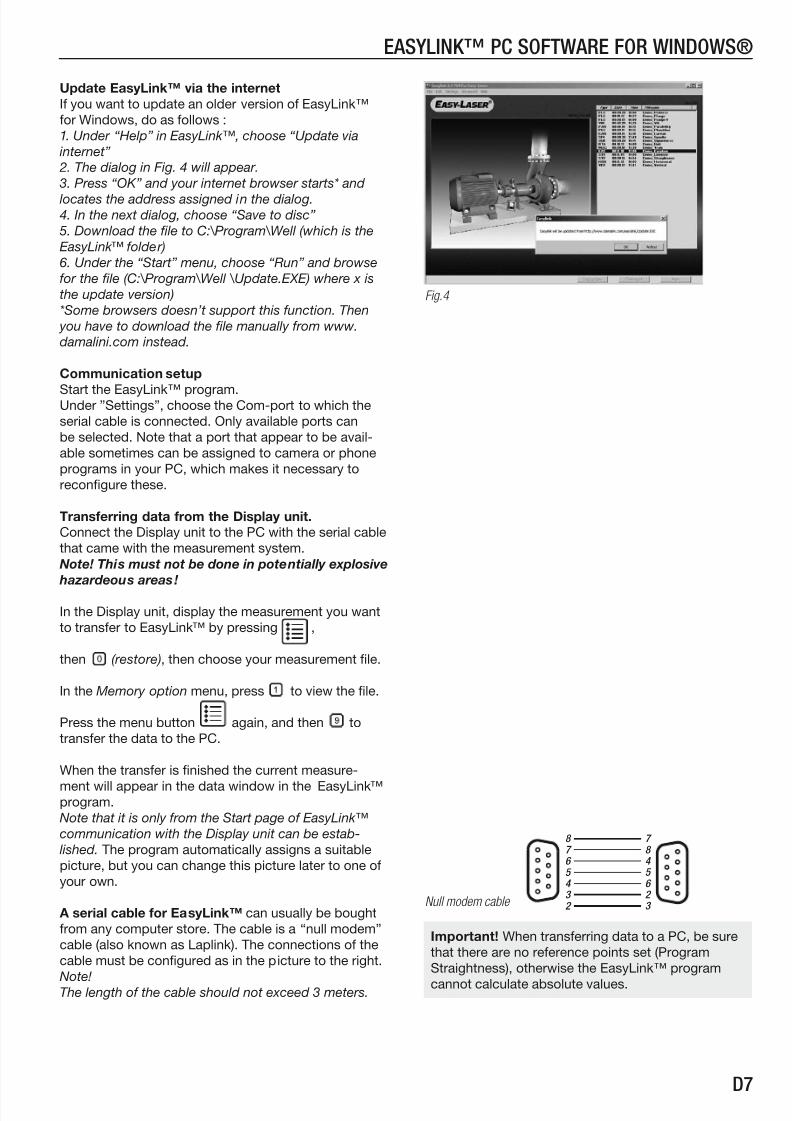
Update EasyLink™ via the internet
If you want to update an older version of EasyLink™
for Windows, do as follows :
1. Under “Help” in EasyLink™, choose “Update via
internet”
2. The dialog in Fig. 4 will appear.
3. Press “OK” and your internet browser starts* and
locates the address assigned in the dialog. 4. In the next dialog, choose “Save to disc”
5. Download the file to C:\Program\Well (which is the
EasyLink™ folder)
6. Under the “Start” menu, choose “Run” and browse
for the file (C:\Program\Well \Update.EXE) where x is
the update version)
*Some browsers doesn’t support this function. Then
you have to download the file manually from www.
damalini.com instead.
Communication setup
Start the EasyLink™ program.Under ”Settings”, choose the Com-port to which the
serial cable is connected. Only available ports can
be selected. Note that a port that appear to be avail-
able sometimes can be assigned to camera or phone
programs in your PC, which makes it necessary to
reconfigure these.
Transferring data from the Display unit.
Connect the Display unit to the PC with the serial cable
that came with the measurement system.
Note! This must not be done in potentially explosive
hazardeous areas!
In the Display unit, display the measurement you want
to transfer to EasyLink™ by pressing ,
then (restore), then choose your measurement file.
In the Memory option menu, press to view the file.
Press the menu button again, and then to
transfer the data to the PC.
When the transfer is finished the current measure-
ment will appear in the data window in the EasyLink™program.
Note that it is only from the Start page of EasyLink™
communication with the Display unit can be estab-
lished. The program automatically assigns a suitable
picture, but you can change this picture later to one of
your own.
A serial cable for EasyLink™ can usually be bought
from any computer store. The cable is a “null modem”
cable (also known as Laplink). The connections of the
cable must be configured as in the picture to the right.
Note!The length of the cable should not exceed 3 meters.
easylink™ Pc sofTWaRe foR WinDoWs®
Fig.4
Important! When transferring data to a PC, be sure
that there are no reference points set (Program
Straightness), otherwise the EasyLink™ program
cannot calculate absolute values.
Null modem cable
8 7 6 5 4 3 2
7 8 4 5 6 2 3

8/11/2019 D550 Extreme Manual Eng
http://slidepdf.com/reader/full/d550-extreme-manual-eng 40/42 D8
easylink™ Pc sofTWaRe foR WinDoWs®
When you start the EasyLink™-program the start window appears with all saved measurements listed to the
right. You can sort these by type of measurement, date, time or file name by clicking at the buttons right above the list.
Open a saved measurement by double clicking on it in the list.
To right-click at a measurement in the list gives you more options (see below).
Sort list by:
Back to unsorted list
Picture window
Roll-down menus
Saved measurements
View report
View graph
Export to spreadsheet
Rename item
Delete item
Add photo
Remove photo
[Right-click at a measurement]
Open database .............................Choose alternative database Export to spreadsheet....................Export to spreadsheet
Print report ................................... (only in measurement window)
Print value list ...............................Prints measurement values and measurement information
Print picture ................ ................ .. (only in measurement window)
Download from other instrument ....Download measurement data from instrument other than Easy-Laser®
Exit ..............................................Exit Program
Copy picture ............(only in measurement window)
Copy value list .........(only in measurement window)
Options......... (see below)
Help
Update via internetSend Email for support
EasyLink registration
About
In the Options dialog you can make settings suitable for you.
Set data base to default (ell.csd).
Settings for graphic functions for some geometry programs.
Choose to which format you want to export your measurement data.
Set Com-port. Only available ports can be selected.
Allows for downloading of measurement data from
instruments other than Easy-Laser®.
Warn if the measurement data being
transmitted is at a low resolution.
Warn if references are set on the measurement
data being transmitted, i.e. if there are points set to
0.00. Then the EasyLink™ program cannot calculateabsolute values.
When having problem nding a Com port that is
available a Deepscan can be made. This means that
the program tries to release Com-ports.
The data base that is displayed when the program is started (default).
8/11/2019 D550 Extreme Manual Eng
http://slidepdf.com/reader/full/d550-extreme-manual-eng 41/42 D9
easylink™ Pc sofTWaRe foR WinDoWs®
Copy the measurement data to other programs
In the Data window to the right the current data is
shown. This data can be copied, and then pasted in to
another document, e.g. Word or Excel documents.
Do like this:
1. Under “Edit”, choose “Copy value list”
2. Open your document
3. Paste the data in [ Ctrl+V ]
Copy the picture window to other programs“Copy Picture” copies the picture in the Picture
window, which you then can paste in to another
document.
Do like this:
1. Press , or under “Edit”,
choose “Copy picture”
2. Open your document
3. Paste the picture in [ Ctrl+V ]
Example: Word document with the Picture window pasted
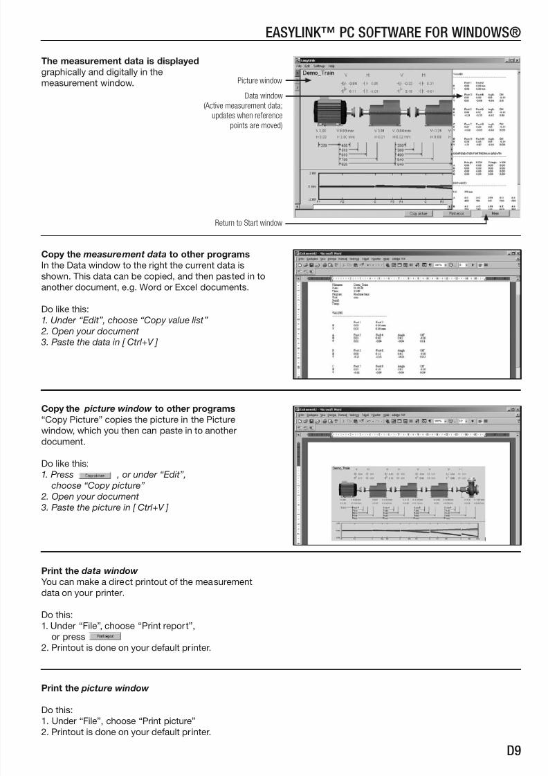
Return to Start window
Data window
(Active measurement data;
updates when reference
points are moved)
Print the picture window
Do this:
1. Under “File”, choose “Print picture”
2. Printout is done on your default printer.
Print the data window
You can make a direct printout of the measurement
data on your printer.
Do this:
1. Under “File”, choose “Print report”,
or press
2. Printout is done on your default printer.
Picture window
The measurement data is displayed
graphically and digitally in the
measurement window.

8/11/2019 D550 Extreme Manual Eng
http://slidepdf.com/reader/full/d550-extreme-manual-eng 42/42
easylink™ Pc sofTWaRe foR WinDoWs®
Copy the screen of the Display unit directly to the
EasyLink™ program
Do this:
1. Connect the Display unit to the PC.
2. Start the EasyLink™ program.
3. Show the display you want to copy from the Display
unit.4. Press to go to the Main menu.
5. Press and the display is directly copied into the
EasyLink™ program, and opened in a new window.
Exporting measurement data to spreadsheet
When exporting to MS Excel, do this (the Excel pro-
gram must be installed on your computer):
1. In the Start window, first left-click once on the mea-
surement, then right-click it to see the pop-up menu.
2. Choose “Export to spreadsheet” in the pop-up
menu.
3. Excel automatically starts and the data is exported
to a new spreadsheet.