Embed Size (px)
Citation preview
DEPT OF EEE EM-1 LAB MANUAL
LENDI INSTITUTE OF ENGINEERING & TECHNOLOGY 1
SWINBURNE’S TESTAND
SPEED CONTROL OF D.C. SHUNT MACHINE
www.jntuworld.com
www.jntuworld.com
www.jwjobs.net

DEPT OF EEE EM-1 LAB MANUAL
LENDI INSTITUTE OF ENGINEERING & TECHNOLOGY 2
Experiment no: 1
SWINBURNE’S TEST AND SPEED CONTROL OF DC SHUNT MACHINE
AIM : To Pre-determine the efficiency and performance characteristics of aDC Shunt machine. (both as a generator & motor). Determination of
the speed characteristics of DC shunt machine by a) Field control b) Armature control
NAME PLATE DETAILS:
S.No Type DC Shunt Motor01 Ratings 3.0 HP02 Volts. 220 V DC03 Current 12 A04 Exc. Volts. 220 V DC05 Exc. Current 0.6A06 Duty S107 Ins. Class B08 Speed 1500 rpm
APPARATUS:
S.No Apparatus Required Rating Type Qty.
01 Voltmeter
02 Ammeter
03 Ammeter
04 Rheostat
05 Tachometer
www.jntuworld.com
www.jntuworld.com
www.jwjobs.net
DEPT OF EEE EM-1 LAB MANUAL
LENDI INSTITUTE OF ENGINEERING & TECHNOLOGY 3
www.jntuworld.com
www.jntuworld.com
www.jwjobs.net
DEPT OF EEE EM-1 LAB MANUAL
LENDI INSTITUTE OF ENGINEERING & TECHNOLOGY 4
www.jntuworld.com
www.jntuworld.com
www.jwjobs.net
DEPT OF EEE EM-1 LAB MANUAL
LENDI INSTITUTE OF ENGINEERING & TECHNOLOGY 5
THEORY:
SWINBURNE’S TEST:-
Ø It is a simple method in which losses are measured separately and from theirknowledge, efficiency at any load can be pre-determined in advance. The onlyrunning test needed is a no load test.
Ø Swinburne s test is applicable to those machines in which flux is practicallyconstant i.e. Shunt wound and Compound wound machines.
Ø The machine is running as a motor on no-load at its rated voltage and its speed beadjusted to its rated value using Shunt regulator.
Ø The no-load armature current Iao is measured using an ammeter, where as shuntfield current Ish is given by another ammeter. The no-load input current is givenby Io = Iao + Ish
Ø Let the supply voltage be V volts
No-load input = V Io watts
Power input to armature = V Iao watts
Power input to shunt = V Ish watts
No-load input supplies Copper losses (Armature & Field), Iron losses (Hysteresis & Eddy current) & Mechanical losses ( Friction losses & Windage).
Constant losses = No load input power Armature copper losses
Wc = V Io – Iao² Ra watts .
Ø Predetermination of efficiency of a motor at any load
Input = V I watts.
Armature Cu losses = Ia2 Ra
Constant losses = Wc
Total losses = Wc + ( I - Ish)² Ra
www.jntuworld.com
www.jntuworld.com
www.jwjobs.net

DEPT OF EEE EM-1 LAB MANUAL
LENDI INSTITUTE OF ENGINEERING & TECHNOLOGY 6
= (Input Total losses) / (Input)
Ø Predetermination of efficiency of a generator at any load
Output = V I watts.
Armature Cu losses = Ia2 Ra
Constant losses = Wc
Total losses = Wc + ( I + Ish)² Ra
= (Output) / (Output + Total losses)
Ø Maximum Efficiency : Variable losses (Ia² Ra) = Constant losses ( Wc)
SPEED CONTROL:
Ø Speed control of DC shunt motor can be done in the following two ways Field control method Armature control method
Field Control Method:-
Ø This method of speed control also called as Field weakening method gives speeds only above the rated speed.
Ø The field flux and the speed of the shunt motor can be controlled easily by varying the field regulating resistance.
Ø By increasing the field circuit resistance under steady conditions, the field current (If) and field flux (Ø) are reduced since the rotor speed cannot change suddenly due to inertia.
Ø This decrease in flux also causes a reduction in the counter EMF. As a result morecurrent flows through the armature.
Ø The percentage increase in the armature current is much more than the percentagedecrease in the field flux and hence electromagnetic torque increases. This beingmore than the load torque, the motor gets accelerated. As field flux is inverselyproportional to speed, as it decreases, the speed of the motor increases at constantarmature voltage.
N = ((V-Ia Ra) 60A) / (ØZP)
www.jntuworld.com
www.jntuworld.com
www.jwjobs.net
DEPT OF EEE EM-1 LAB MANUAL
LENDI INSTITUTE OF ENGINEERING & TECHNOLOGY 7
N proportional to 1/Ø
Armature control method:-
Ø This method is used when speeds below the no load speed are required.Ø As the supply voltage is normally constant, the voltage across the armature
is varied by inserting a variable rheostat in series with the armature. Thepotential difference across the armature is decreased, thereby decreasing thearmature speed.
Eb = (ZNØP) / (60A)
Eb N
Therefore at constant flux (field current), as the voltage across the armature increases, the speed of the motor also increases and vice versa.
PROCEDURE:
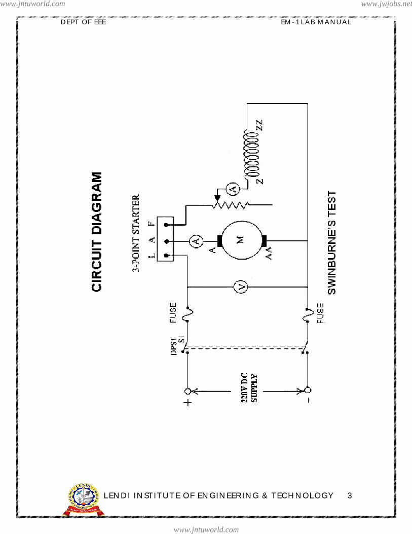
SWINBURNE’S TEST
1. Connect the circuit as per the Circuit diagram.2. Initially the starter must be in off position.3. Switch on the D.C. Motor to 220V D.C. Supply by closing the DPST Switch.4. Start the D.C. motor using the three point starter and thereby adjust the speed
to its rated speed using field rheostat.5. Note down the readings of Voltmeter & Ammeters in Table6. Switch off the D.C. Motor from 220V D.C. Supply by opening the DPST Switch.
SPEED CONTROL
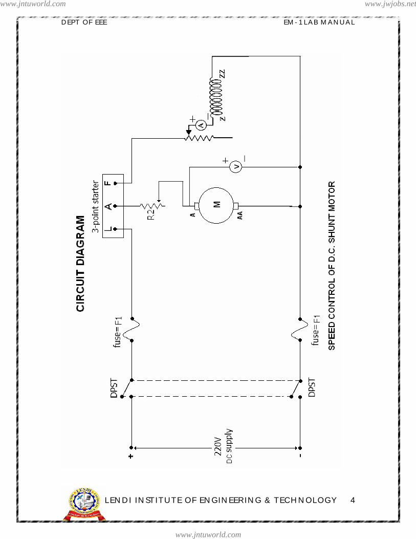
1. Connect the circuit as shown in the circuit diagram.2. Keep the armature rheostat resistance at maximum position and the field rheostat
at minimum position before starting the experiment.3. The DC supply is switched ON and motor is started with the help of a three point
starter.4. Keep the field current constant and vary the rheostat in series with the armature.5. Note down the corresponding readings of the voltmeter across the armature and
speed of the DC shunt motor.
www.jntuworld.com
www.jntuworld.com
www.jwjobs.net
DEPT OF EEE EM-1 LAB MANUAL
LENDI INSTITUTE OF ENGINEERING & TECHNOLOGY 8
6. Now the rheostat of the armature is kept as it is and now the field rheostat isvaried and note down the corresponding readings of field current and the speed ofthe DC shunt motor.
OBSERVATION TABLES:
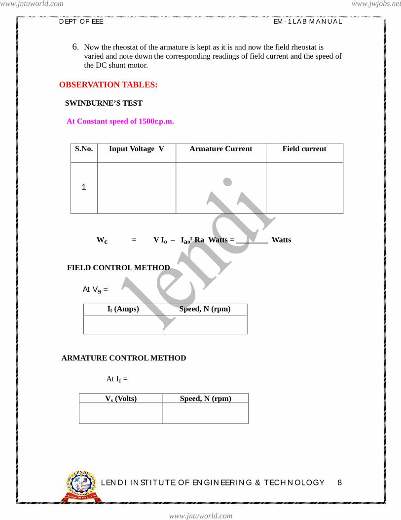
SWINBURNE’S TEST
At Constant speed of 1500r.p.m.
S.No. Input Voltage V Armature Current Field current
1
Wc = V Io – Iao² Ra Watts = ________ Watts
FIELD CONTROL METHOD
At Va =
If (Amps) Speed, N (rpm)
ARMATURE CONTROL METHOD
At If =
Vs (Volts) Speed, N (rpm)
www.jntuworld.com
www.jntuworld.com
www.jwjobs.net

DEPT OF EEE EM-1 LAB MANUAL
LENDI INSTITUTE OF ENGINEERING & TECHNOLOGY 9
CALCULATION TABLE:
SWINBURNE’S TEST:
I) For Motor
S.No.
InputVoltage
(V)
InputCurrent(I)
Fieldcurrent(Ish)
ArmatureCopperLosses
TotalLosses
InputPower
12...
10
II) For Generator
S.No.
OutputVoltage
(V)
OutputCurrent
(I)
Fieldcurrent
(Ish)
ArmatureCopperLosses
TotalLosses
OutputPower
12...
10
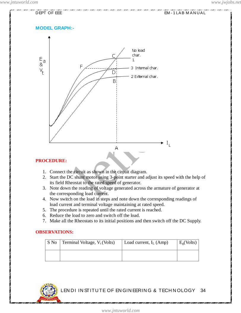
MODEL GRAPHS:
SWINBURNE’S TEST
www.jntuworld.com
www.jntuworld.com
www.jwjobs.net

DEPT OF EEE EM-1 LAB MANUAL
LENDI INSTITUTE OF ENGINEERING & TECHNOLOGY 10
Field current IfFIELD CONTROL METHOD AT CONSTANT ARMATURE VOLTAGE
Armature voltage Va voltsArmature control method at constant field current
www.jntuworld.com
www.jntuworld.com
www.jwjobs.net

DEPT OF EEE EM-1 LAB MANUAL
LENDI INSTITUTE OF ENGINEERING & TECHNOLOGY 11
PRECAUTIONS:-
1. The field rheostat of the motor must be kept in minimum before switching on the220V D.C. supply.
2. Ensure that the starter arm is at extreme left position.3. Avoid loose connections4. Note down the readings from the meters without any parallax error
RESULTS:
Ø Constant losses = _________ Watts
Ø Current at which Max. occurs for motor = _________ A
Ø Current at which Max. occurs for generator = _________ A
Ø Maximum Efficiency for motor = __________ %.
Ø Maximum Efficiency for generator = __________ %.
CONCLUSIONS:
VIVA VOCE QUESTIONS:
1 What is the significance of Swinburne s test? 2 What are the advantages & disadvantages of this test?
3 Why this test is not suitable for D.C series motor? 4 What is the purpose of 3 point starter? 5 What happens if field is open in D.C motor? 6 Why we have to keep the field rheostat in minimum position?
7 In how many ways , we can control the sped? 8 Compare the speed control methods? 9 What are the different losses in D.C machines?10 What is the purpose of starter?11 How do you reduce the iron losses?
www.jntuworld.com
www.jntuworld.com
www.jwjobs.net

DEPT OF EEE EM-1 LAB MANUAL
LENDI INSTITUTE OF ENGINEERING & TECHNOLOGY 12
LOAD CHARACTERISTICS OF A DC
SHUNT GENERATOR
www.jntuworld.com
www.jntuworld.com
www.jwjobs.net
DEPT OF EEE EM-1 LAB MANUAL
LENDI INSTITUTE OF ENGINEERING & TECHNOLOGY 13
Experiment no: 2
LOAD CHARACTERISTICS OF A DC SHUNT GENERATOR
AIM : To determine the internal and external characteristics of dc shunt generator by performing a load test.
NAME PLATE DETAILS:
Type DC Shunt Motor DC Shunt Generator
Ratings 3.0 HP 2 KW
Volts. 220 V DC 220 V DC
Current 12 A 12A
Exc. Volts. 220 V DC 220 V DC
Exc. Current 0.6A 0.7A
Duty S1 S1
Ins. Class B B
Speed 1500 rpm 1500 rpm
APPARATUS:
S.No Apparatus Required Rating Type Qty.
01 Voltmeter
02 Ammeter
03 Ammeter
04 Rheostat
05 Tachometer
06 Fuse
www.jntuworld.com
www.jntuworld.com
www.jwjobs.net
DEPT OF EEE EM-1 LAB MANUAL
LENDI INSTITUTE OF ENGINEERING & TECHNOLOGY 14
www.jntuworld.com
www.jntuworld.com
www.jwjobs.net
DEPT OF EEE EM-1 LAB MANUAL
LENDI INSTITUTE OF ENGINEERING & TECHNOLOGY 15
THEORY:
Ø Generator is run at rated speed and the field current is adjusted to give ratedvoltage at no load.
Ø DPST is closed and the load is gradually increased in steps and the readings arerecorded at each step. A plot of terminal voltage Vt and load current IL withrespect to the particular value of field current If and speed gives the externalcharacteristic curves.
Ø The drop in voltage is due to Ra drop, reduction of main field flux due to armaturereaction and further reduction in If.
Ø This test is applicable for two similar shunt machines. The two machines arecoupled mechanically. One machine runs normally as a motor and drivesgenerator.
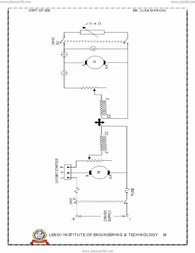
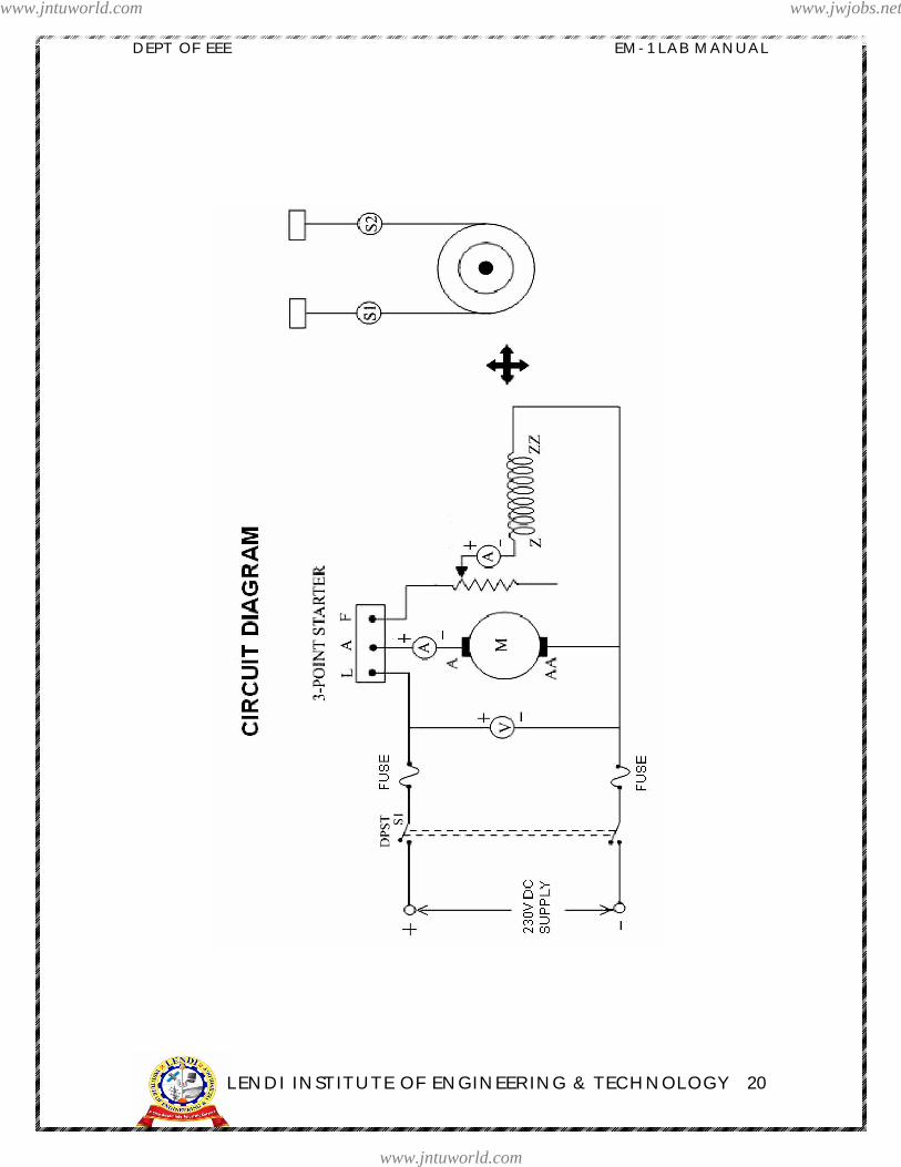
PROCEDURE:
1. Connect the circuit as per the circuit diagram.2. Close the DPST1 switch and start the motor with the help of starter.3. Adjust the field regulator of the motor till the generator reaches it s rated speed.4. By adjusting the field regulator of the generator rated voltage can be applied to the generator at it s terminals.5. Apply the load gradually in steps by closing the switch DPST2 and note down the readings of the load current, terminal voltage and field current of the generator for every change in load.
6. Continue the above said procedure until the ammeter shows a reading of near to full load current.
7. Then bring the rheostats to initial positions and switch off the supply
OBSERVATION TABLE:
Fieldcurrent, If
Terminalvoltage, Vt
Load current,IL
Armaturecurrent, Ia
Generatedemf, Eg
www.jntuworld.com
www.jntuworld.com
www.jwjobs.net

DEPT OF EEE EM-1 LAB MANUAL
LENDI INSTITUTE OF ENGINEERING & TECHNOLOGY 16
CALCULATIONS:
Armature current = load current + field current Ia = IL + IfGenerated emf = terminal voltage + armature resistance drop Eg = Vt +IaRa
MODEL GRAPHS:
AB drop in field current, BC Armature reaction drop, CD IaRa drop
www.jntuworld.com
www.jntuworld.com
www.jwjobs.net
DEPT OF EEE EM-1 LAB MANUAL
LENDI INSTITUTE OF ENGINEERING & TECHNOLOGY 17
PRECAUTIONS:
Ø Field regulator of the motor must be in minimum position while starting themotor.
Ø While loading the generator, at each step, the speed of the generator ismaintained at its rated value.
Ø Generator should not be overloaded.Ø Ensure that the starter arm is at extreme left position.Ø Avoid loose connectionsØ Note down the readings from the meters without any parallax errorØ Tachometer should be kept horizontal to the shaft while measuring the speed.Ø Before switch OFF the motor make sure that there is no load connected to motor
RESULTS:
CONCLUSIONS:
VIVA VOCE QUESTIONS:
1) what is the difference between internal & external Characteristics?2) What are the applications of D.C shunt Generator?3) Why the field rheostat of the Generator should be kept in maximum position?4) What is voltage regulation ?5) What is residual voltage?6) What are the losses in D.C Shunt Generator?
www.jntuworld.com
www.jntuworld.com
www.jwjobs.net

DEPT OF EEE EM-1 LAB MANUAL
LENDI INSTITUTE OF ENGINEERING & TECHNOLOGY 18
BRAKE TEST ON AD.C. SHUNT MOTOR
www.jntuworld.com
www.jntuworld.com
www.jwjobs.net

DEPT OF EEE EM-1 LAB MANUAL
LENDI INSTITUTE OF ENGINEERING & TECHNOLOGY 19
Experiment no: 3
BRAKE TEST ON A D.C. SHUNT MOTOR
AIM : To obtain the Performance characteristics curves of a D.C. shunt motor byconducting brake test on it.
NAME PLATE DETAILS:
S.No Type DC Shunt Motor01 Rating 3.0 HP02 Volts. 220 V DC03 Current 12 A04 Exc. Volts. 220 V DC05 Exc. Current 0.6A06 Duty S107 Ins. Class B08 Speed 1500 rpm
APPARATUS:
S.No Apparatus Required Rating Type Qty.
01 Voltmeter
02 Ammeter
03 Ammeter
04 Rheostat
05 Tachometer
06 Fuse
www.jntuworld.com
www.jntuworld.com
www.jwjobs.net
DEPT OF EEE EM-1 LAB MANUAL
LENDI INSTITUTE OF ENGINEERING & TECHNOLOGY 20
www.jntuworld.com
www.jntuworld.com
www.jwjobs.net

DEPT OF EEE EM-1 LAB MANUAL
LENDI INSTITUTE OF ENGINEERING & TECHNOLOGY 21
THEORY:
Ø It is a simple method of testing low rating DC machines and consists of applyinga brake to a water-cooled drum mounted on the motor shaft.
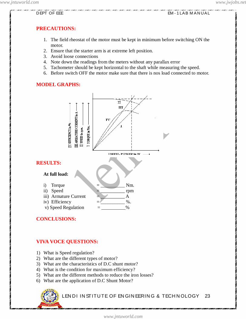
Ø The four important characteristics curves of a D.C. Shunt Motor, namely,Torque, Speed, Armature Current & efficiency, each plotted against the usefulPower, as shown in the model graph are known as Performance characteristics
Ø A belt is wound round the brake drum and its two ends are attached to two springbalances S1 & S2. The tension of the belt can be adjusted with the help of swivels.
Ø The force acting tangentially on the drum is equal to the difference between thereadings of the two spring balances.
Ø The net force, F applied on the brake drum is 9.81(S1 S2) Newtons where , S1 & S2 are the readings of Spring balances 1& 2 in Kg.f.
Ø Shaft torque, T developed by the motor is 9.81 (S1 S2) R Nm where, R is the radius of the pulley in meters & N is the speed in rpm
Ø Useful Output Power = (2 N T) / 60 Watts
Ø Input Power = V IL Watts, where IL = (Ia + Ish)
Ø % Efficiency , = (Output power / Input power) x 100.
Ø Speed Regulation = [ (No Load speed ) ( Full load speed )] / Full Load.
Ø The size of the motor that can be tested by this method is limited from theconsideration of the heat that can be dissipated at the brake drum
Ø Where the output power exceeds about 2 H.P., or where the test is of longduration, it s necessary to use a water cooled brake drum.
PROCEDURE:
1. Connect the circuit as per the Circuit diagram.2. Initially the starter must be in off position.3. Switch on the D.C. Motor to 220V D.C. Supply by closing the DPST Switch.4. Start the D.C. motor using the three point starter and thereby adjust the speed
to its rated speed using field rheostat.5. Note down the readings of Voltmeter & Ammeters in Table under No Load
condition.
www.jntuworld.com
www.jntuworld.com
www.jwjobs.net

DEPT OF EEE EM-1 LAB MANUAL
LENDI INSTITUTE OF ENGINEERING & TECHNOLOGY 22
6. Apply the Load on the drum gradually in steps by tightening the belt around it.At each step, note down the readings of the Ammeters, Voltmeter, two Springbalances and the Tachometer.
7. Pour water in the pulley and cool it often when the motor is loaded. 8. When the full load is reached, slowly reduce the load and switch off the
Motor from 220V D.C. Supply by opening the DPST Switch
OBSERVATION TABLE:
S.No. InputVoltage
(V)
ArmatureCurrent
(Ia)
Fieldcurrent
(Ish)
Spring BalancesSpeed (N)
S1 S2
123....
10
CALCULATION TABLE:
Radius of the Brake Drum, R = ______ mts.
S.No.Input
Voltage(V)
InputCurrent
(IL)Torque,Nm
(T)OutputPower
InputPower %
123....
10
www.jntuworld.com
www.jntuworld.com
www.jwjobs.net
DEPT OF EEE EM-1 LAB MANUAL
LENDI INSTITUTE OF ENGINEERING & TECHNOLOGY 23
PRECAUTIONS:
1. The field rheostat of the motor must be kept in minimum before switching ON themotor.
2. Ensure that the starter arm is at extreme left position.3. Avoid loose connections4. Note down the readings from the meters without any parallax error5. Tachometer should be kept horizontal to the shaft while measuring the speed.6. Before switch OFF the motor make sure that there is nos load connected to motor.
MODEL GRAPHS:
RESULTS:
At full load:
i) Torque = __________ Nm.ii) Speed = __________ rpmiii) Armature Current = __________ Aiv) Efficiency = __________ %.
v) Speed Regulation = __________%
CONCLUSIONS:
VIVA VOCE QUESTIONS:
1) What is Speed regulation?2) What are the different types of motor?3) What are the characteristics of D.C shunt motor?4) What is the condition for maximum efficiency?5) What are the different methods to reduce the iron losses?6) What are the application of D.C Shunt Motor?
www.jntuworld.com
www.jntuworld.com
www.jwjobs.net

DEPT OF EEE EM-1 LAB MANUAL
LENDI INSTITUTE OF ENGINEERING & TECHNOLOGY 24
MAGNETIZATIONCHARACTERISTICS OF AD.C. SHUNT GENERATOR
www.jntuworld.com
www.jntuworld.com
www.jwjobs.net
DEPT OF EEE EM-1 LAB MANUAL
LENDI INSTITUTE OF ENGINEERING & TECHNOLOGY 25
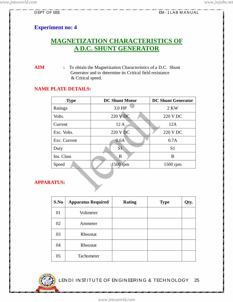
Experiment no: 4
MAGNETIZATION CHARACTERISTICS OFA D.C. SHUNT GENERATOR
AIM : To obtain the Magnetization Characteristics of a D.C. ShuntGenerator and to determine its Critical field resistance
& Critical speed.
NAME PLATE DETAILS:
Type DC Shunt Motor DC Shunt Generator
Ratings 3.0 HP 2 KW
Volts. 220 V DC 220 V DC
Current 12 A 12A
Exc. Volts. 220 V DC 220 V DC
Exc. Current 0.6A 0.7A
Duty S1 S1
Ins. Class B B
Speed 1500 rpm 1500 rpm
APPARATUS:
S.No Apparatus Required Rating Type Qty.
01 Voltmeter
02 Ammeter
03 Rheostat
04 Rheostat
05 Tachometer
www.jntuworld.com
www.jntuworld.com
www.jwjobs.net
DEPT OF EEE EM-1 LAB MANUAL
LENDI INSTITUTE OF ENGINEERING & TECHNOLOGY 26
www.jntuworld.com
www.jntuworld.com
www.jwjobs.net
DEPT OF EEE EM-1 LAB MANUAL
LENDI INSTITUTE OF ENGINEERING & TECHNOLOGY 27
THEORY:
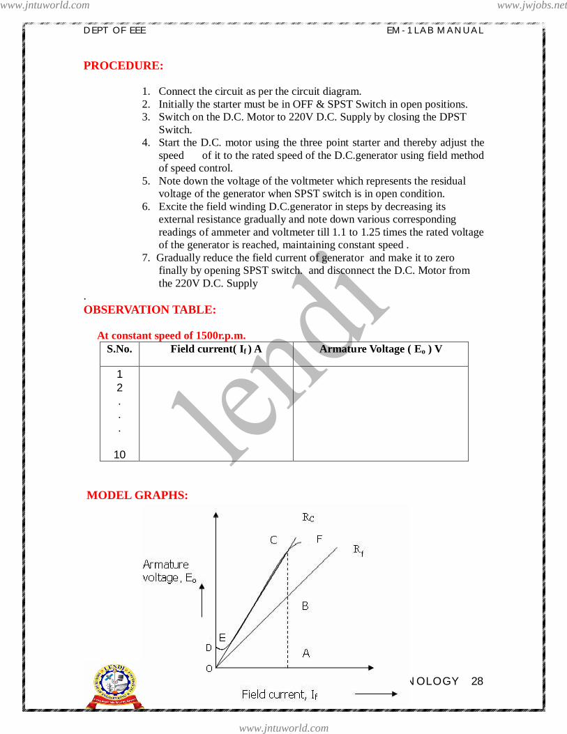
I) Magnetization Characteristics
Ø The magnetization characteristics shows the relation between the no loadgenerated emf in armature, E0 and the field (or) exciting current, If at a givenfixed speed as shown in model graph.
Ø These characteristics are also known as the No load saturation characteristics orOpen circuit characteristics. The shape of these characteristics is practically samefor all generators whether separately excited or self excited
Ø Due to the residual magnetism in the poles, some emf is generated even whenIf = 0 represented by OD**. Hence, the curve starts a little way up.
Ø The slight curvature, DE** at the lower end is due to magnetic inertia. It is seenthat the first part of the curve, EC** is practically straight. This is due to the factthat at low flux densities, reluctance of iron path being negligible (due to highpermeability), total reluctance is given by the air gap reluctance, which isconstant. Hence, the flux and consequentially the generated emf are directlyproportional to the exciting current.
Ø How ever at high flux densities, where µ is small, iron path reluctance becomesappreciable and straight relation, CF** between Eo and If no longer holds good,i.e., saturation of poles start.
(** refers to the model graph)
II) Critical resistance
Ø It is that maximum value of the field resistance, above which the machine fails toexcite i.e. there will be no build up of the voltage.
Ø This resistance corresponds to the straight-line position of the magnetizationcharacteristic because the magnetic circuit does not offer any appreciablereluctance to the magnetic flux.
III) Critical speed
Ø It is that speed for which the given shunt field resistance will represent criticalfield resistance
(OR)
It is that minimum value of the speed of the machine below which the machine fails to excite .
www.jntuworld.com
www.jntuworld.com
www.jwjobs.net
DEPT OF EEE EM-1 LAB MANUAL
LENDI INSTITUTE OF ENGINEERING & TECHNOLOGY 28
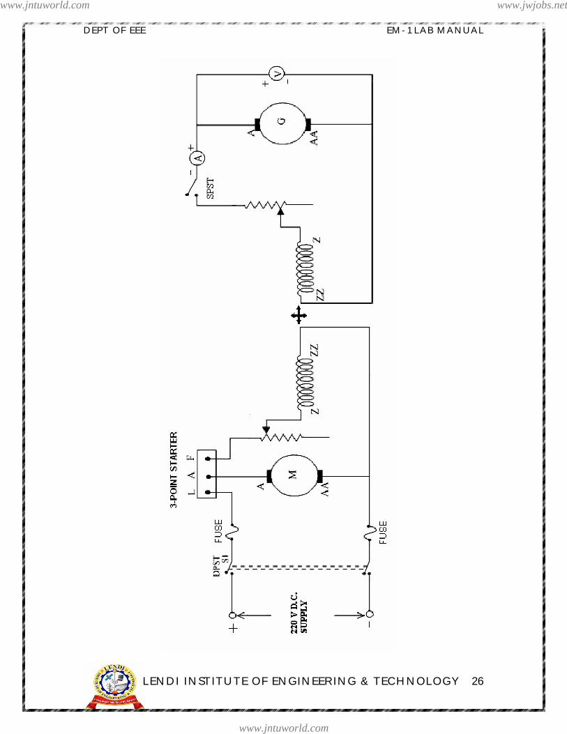
PROCEDURE:
1. Connect the circuit as per the circuit diagram.2. Initially the starter must be in OFF & SPST Switch in open positions.3. Switch on the D.C. Motor to 220V D.C. Supply by closing the DPST
Switch.4. Start the D.C. motor using the three point starter and thereby adjust the
speed of it to the rated speed of the D.C.generator using field methodof speed control.
5. Note down the voltage of the voltmeter which represents the residualvoltage of the generator when SPST switch is in open condition.
6. Excite the field winding D.C.generator in steps by decreasing itsexternal resistance gradually and note down various correspondingreadings of ammeter and voltmeter till 1.1 to 1.25 times the rated voltageof the generator is reached, maintaining constant speed .
7. Gradually reduce the field current of generator and make it to zerofinally by opening SPST switch. and disconnect the D.C. Motor fromthe 220V D.C. Supply
.OBSERVATION TABLE:
At constant speed of 1500r.p.m.S.No. Field current( If ) A Armature Voltage ( Eo ) V
12...
10
MODEL GRAPHS:
www.jntuworld.com
www.jntuworld.com
www.jwjobs.net
DEPT OF EEE EM-1 LAB MANUAL
LENDI INSTITUTE OF ENGINEERING & TECHNOLOGY 29
CALCULATIONS:
TO FIND CRITICAL FIELD RESISTANCE:
1. Plot the magnetization curve.2. Draw the tangent such that it touches most of the linear part of the curve. This line is the Critical field resistance line.3. The slope of the above line gives the Critical field resistance.
TO FIND CRITICAL SPEED:
1. Draw the constant field resistance line Rf .2. From point draw a line on to the Critical field resistance line. Now the Critical speed, Nc = (AB /AC) ×N, where N is the rated speed of D.C. generator i.e., 1500 r.p.m.
PRECAUTIONS:-
5. The field rheostat of the motor must be kept in minimum & for the generator inmaximum positions before switching on the D.C. supply.
6. Ensure that the starter arm is at extreme left position.7. Avoid loose connections8. Note down the readings form the meters without any parallax error
RESULT:
Ø Critical field resistance = ________ ohms.
Ø Critical speed = ________ r.p.m.
CONCLUSIONS:
VIVA VOCE QUESTIONS:
1. What are Magnetization Characteristics?2. What do you mean by Critical field resistance?3. What do you mean by Critical speed?4. How do you obtain the O.C.C at any other speed other than rated speed?5. What are the different types of Generators?6. What are the applications of D.C Shunt Generators?
www.jntuworld.com
www.jntuworld.com
www.jwjobs.net

DEPT OF EEE EM-1 LAB MANUAL
LENDI INSTITUTE OF ENGINEERING & TECHNOLOGY 30
LOAD TEST ON DCSERIES GENERATOR
www.jntuworld.com
www.jntuworld.com
www.jwjobs.net
DEPT OF EEE EM-1 LAB MANUAL
LENDI INSTITUTE OF ENGINEERING & TECHNOLOGY 31
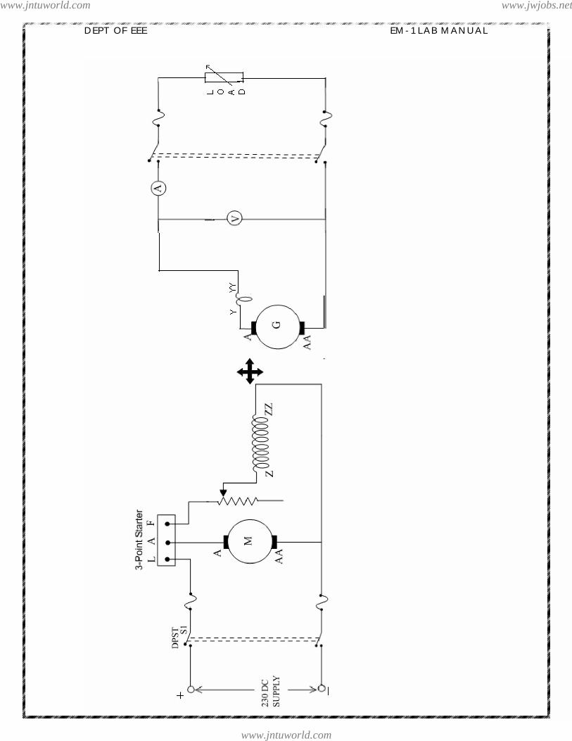
Experiment no: 5
LOAD TEST ON DC SERIES GENERATOR
Aim : To perform load test on a DC series generator and to draw the initial and externalcharacteristics.
Name Plate Details:
Type DC Shunt Motor DC Series Generator
Ratings 3.0 HP 2 KW
Volts. 220 V DC 220 V DC
Current 12 A 12A
Exc. Volts. 220 V DC 220 V DC
Exc. Current 0.6A 0.7A
Duty S1 S1
Ins. Class B B
Speed 1500 rpm 1500 rpm
Apparatus:
S.No Apparatus Required Rating Type Qty.
01 Voltmeter
02 Ammeter
03 Rheostat
04 Rheostat
05 Tachometer
www.jntuworld.com
www.jntuworld.com
www.jwjobs.net
DEPT OF EEE EM-1 LAB MANUAL
LENDI INSTITUTE OF ENGINEERING & TECHNOLOGY 32
www.jntuworld.com
www.jntuworld.com
www.jwjobs.net
DEPT OF EEE EM-1 LAB MANUAL
LENDI INSTITUTE OF ENGINEERING & TECHNOLOGY 33
THEORY:-
NO-LOAD CHARACTERISTIC: In a DC series generator the armature winding and field winding and load
resistance are connected in series, therefore the field current is equal to the armature orload current. In view of this, even though the series field current is zero the generator willbuild some voltage which is due to residual flux and is known as residual voltage and it isvery low when the load is opened. However if the generator terminals are closed, throughthe load rheostat the armature current will flow. This improves the residual flux and thenresidual voltage. The magnetization curve at one speed for a series generator is illustratedby curve 1.
EXTERNAL CHARACTERISTICS (Eg Vs Ia): This is known as total characteristics which give the relation between EMF
actually induced in armature and armature current.When the load side switch is open, the small voltage due to residual flux will
be indicated by the voltmeter. When that switch is closed field current equal to loadcurrent starts flowing. If the current in series field produces a flux aiding the residualflux, the generator will build up voltage till point C is reached. At point C the fieldresistance line OC meets the saturation curve. The field resistance line OC depends on thetotal resistance in series circuit i.e., it implies the slope of the line OC is determined bythe sum of the armature circuit resistance, series field resistance and load resistance. Ifthe total resistance is more than the critical field resistance, just like a self-excited shuntgenerator, the build up process will not begin. Increase the load on dc series generator insteps and at each step, record load voltage and load current. A curve passing throughthese plotted points gives external characteristic of curve 2. In the figure shown AB isload voltage or armature terminal voltage for a load current of OA.
INTERNAL CHARACTERISTICS (V vS IL):
This is known as Performance characteristics which give the relation betweenterminal voltage and load current.
If total resistance drop IaR is added to the ordinates of curve2, the internalcharacteristic shown by curve 3 is obtained. R is the sum of series field resistance andarmature circuit resistance (including brushes).Thus voltage drop BD is equal to the totalarmature resistance drop IaR and the voltage drop CD is due to armature reaction. Ahorizontal line through D meets the magnetization curve at F and DF givesdemagnetizing effect caused by the armature reaction for a load current equal to OA.
www.jntuworld.com
www.jntuworld.com
www.jwjobs.net
DEPT OF EEE EM-1 LAB MANUAL
LENDI INSTITUTE OF ENGINEERING & TECHNOLOGY 34
MODEL GRAPH:-
PROCEDURE:
1. Connect the circuit as shown in the circuit diagram.2. Start the DC shunt motor using 3-point starter and adjust its speed with the help of
its field Rheostat to the rated speed of generator.3. Note down the reading of voltage generated across the armature of generator at
the corresponding load current.4. Now switch on the load in steps and note down the corresponding readings of
load current and terminal voltage maintaining at rated speed.5. The procedure is repeated until the rated current is reached.6. Reduce the load to zero and switch off the load.7. Make all the Rheostats to its initial positions and then switch off the DC Supply.
OBSERVATIONS:
S No Terminal Voltage, Vt (Volts) Load current, IL (Amp) Eg(Volts)
www.jntuworld.com
www.jntuworld.com
www.jwjobs.net
DEPT OF EEE EM-1 LAB MANUAL
LENDI INSTITUTE OF ENGINEERING & TECHNOLOGY 35
MODEL CALCULATIONS:
IL = Load current IA = Armature current V = Terminal Voltage Eg = Generated EMF = V+ IL(Ra+Rse)
PRECAUTIONS:-
1. The connections should be tight and clear.2. Before starting the DC machine, the armature and field rheostats should be kept
at maximum and minimum positions.
RESULT:
CONCLUSION:
VIVA QUESTIONS:
1. What is a DC series generator?
2. What are the factors on which the generated emf in a DC series generator depends?
3. Why is value of the series field resistance low?
4. Comment on the shapes of the load characteristics of DC series generator.
5. How does armature reaction affect the terminal voltage of a DC series generator at
high load current?
www.jntuworld.com
www.jntuworld.com
www.jwjobs.net
DEPT OF EEE EM-1 LAB MANUAL
LENDI INSTITUTE OF ENGINEERING & TECHNOLOGY 36
HOPKINSON’S TESTON
D.C. SHUNT MACHINES
www.jntuworld.com
www.jntuworld.com
www.jwjobs.net
DEPT OF EEE EM-1 LAB MANUAL
LENDI INSTITUTE OF ENGINEERING & TECHNOLOGY 37
HOPKINSON’S TEST ON DC SHUNT MACHINES
Experiment no:6
Aim : To perform Hopkinson s test on a given motor generator set and determine theefficiency of both motor and generator.
Name Plate Details:
Type DC Shunt Motor DC Shunt Generator
Ratings 3.0 HP 2 KW
Volts. 220 V DC 220 V DC
Current 12 A 12A
Exc. Volts. 220 V DC 220 V DC
Exc. Current 0.6A 0.7A
Duty S1 S1
Ins. Class B B
Speed 1500 rpm 1500 rpm
Apparatus:
S.No Apparatus Required Rating Type Qty.
01 Voltmeter
02 Ammeter
03 Ammeter
04 Rheostat
05 Tachometer
06 Fuse
www.jntuworld.com
www.jntuworld.com
www.jwjobs.net

DEPT OF EEE EM-1 LAB MANUAL
LENDI INSTITUTE OF ENGINEERING & TECHNOLOGY 38
www.jntuworld.com
www.jntuworld.com
www.jwjobs.net
DEPT OF EEE EM-1 LAB MANUAL
LENDI INSTITUTE OF ENGINEERING & TECHNOLOGY 39
Theory:
Ø Hopkinson s test is also known as back to back test. This test is regenerative test.Ø By this method full-load test can be carried out on two shunt machines, preferably
identical machines without wasting their output.Ø The two machines are mechanically coupled and their fields are so adjusted that one
of them acts as motor and the other acts as generator.Ø The power taken from the supply is that required to overcome the losses only.Ø Two identical machines of any size can be tested under full load condition and
therefore this method is very useful for determining efficiency and also a heat runtest for determining the temperature rise.
Ø The electrical output of the generator plus the small power taken from the supply istaken in by the motor and given out as mechanical power after supplying the motorlosses.
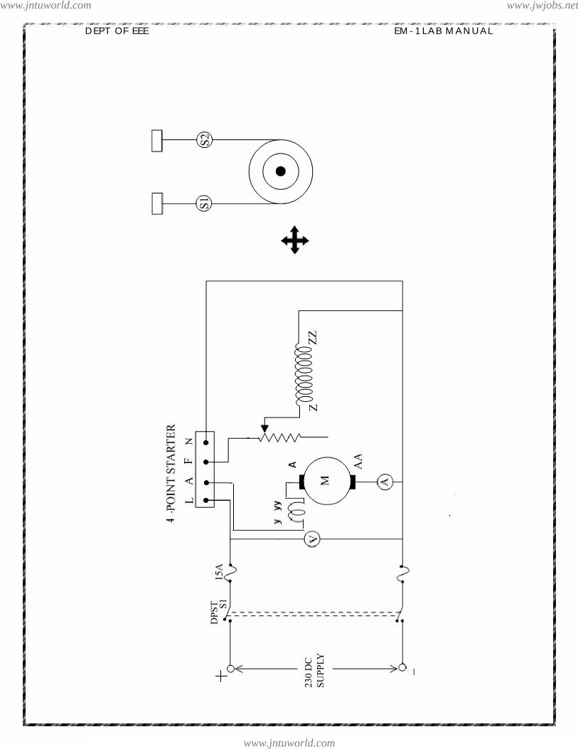
PROCEDURE:
1. Connect the circuit as per the circuit diagram2. Keep the field rheostats of motor, generator at minimum, and maximum positions
respectively.3. Close the DPST switch and open the switch .4. Start the motor using the 3-point starter and adjust the speed to the rated value.5. Build up the voltage across the generator by adjusting the field current till the
voltmeter across switch S2 is zero then close the switch S2.6. Note down the readings of all the ammeters and voltmeters.7. Switch off the DC supply.
OBSERVATIONS:
MODEL CALCULATIONS:
Supply voltage = VMotor armature resistance = RamGenerator armature resistance = RagMotor armature current = IamGenerator armature current = IagMotor field current = IfmGenerator field current = IfgCurrent taken from supply = ILMotor armature copper losses = Iam
2 RamMotor field copper losses = V IfmGenerator armature copper losses = Iag
2 Rag
S.No VT(V) IL(A) Ifm(A) Iag(A) Ifg(A) VG(V)
www.jntuworld.com
www.jntuworld.com
www.jwjobs.net
DEPT OF EEE EM-1 LAB MANUAL
LENDI INSTITUTE OF ENGINEERING & TECHNOLOGY 40
Generator field copper losses = V IfgPower drawn from the supply = V ILTotal stray losses (Wc) = VIL (Iam
2 Ram+ Iag2 Rag+ V Ifm+ V Ifg)
Stray losses per machine = Wc / 2
Motor:
Motor Input = V ( Iam + Ifm)Motor losses = Armature copper losses + Shunt copper losses + Stray losses = Iam
2 Ram +V Ifm+ Wc/ 2
Generator:
Generator output = V IagGenerator losses = Armature copper losses + Shunt copper losses + Stray losses = Iag
2 Rag +V Ifg + Wc/ 2
Generator efficiency =
GRAPHS :1.Output VS Efficiency (of generator)2. Output VS Efficiency (of motor)
PRECAUTIONS:
1. The switch S is closed only when the voltmeter across the switch reads zero.2. Loose connections are to be avoided.3. The rheostats are to be kept at proper positions while starting the motor.4. The readings of all the metres are to be noted down without any error.
RESULT:
www.jntuworld.com
www.jntuworld.com
www.jwjobs.net
DEPT OF EEE EM-1 LAB MANUAL
LENDI INSTITUTE OF ENGINEERING & TECHNOLOGY 41
CONCLUSIONS:
VIVA QUESTIONS:
1. What is the purpose of Hopkinson s test?2. What are the advantages of Hopkinson s test?3. What are the conditions for conducting the test?4. Why the adjustments are done in the field rheostat of generator and motor?5. If the voltmeter across the SPST switch reads zero what does it indicate?6. If the field got opened in the running condition in DC shunt generator what happens?
www.jntuworld.com
www.jntuworld.com
www.jwjobs.net

DEPT OF EEE EM-1 LAB MANUAL
LENDI INSTITUTE OF ENGINEERING & TECHNOLOGY 42
BRAKE TEST ON D.C. COMPOUND MOTOR
www.jntuworld.com
www.jntuworld.com
www.jwjobs.net

DEPT OF EEE EM-1 LAB MANUAL
LENDI INSTITUTE OF ENGINEERING & TECHNOLOGY 43
Experiment no:7
BRAKE TEST ON A DC COMPOUND MOTOR
Aim : To perform Brake test on a given D.C. Compound motor and obtain theperformance characteristics of the motor from the test observation.
Name Plate Details:
S.No Type DC compound Motor01 Rating 3.0 HP02 Volts. 220 V DC03 Current 12 A04 Exc. Volts. 220 V DC05 Exc. Current 0.6A06 Duty S107 Ins. Class B08 Speed 1500 rpm
Apparatus:
S.No Apparatus Required Rating Type Qty.
01 Voltmeter
02 Ammeter
03 Ammeter
04 Rheostat
05 Tachometer
06 Fuse
www.jntuworld.com
www.jntuworld.com
www.jwjobs.net
DEPT OF EEE EM-1 LAB MANUAL
LENDI INSTITUTE OF ENGINEERING & TECHNOLOGY 44
www.jntuworld.com
www.jntuworld.com
www.jwjobs.net

DEPT OF EEE EM-1 LAB MANUAL
LENDI INSTITUTE OF ENGINEERING & TECHNOLOGY 45
THEORY:
It is a direct method and consists of applying brake to a water cooled pulleymounted on the motor shaft. The simple brake test can be used for small motors only.Because, in case of large motors, it is difficult to dissipate the large amount of heatgenerated at the brake. The simple method of measuring motor output is by the use ofpulley brake method. A rope is wound round the pulley and its two ends are attached totwo spring balances S1 & S2. The tension of the rope can be adjusted with the help ofswivels. The force acting tangentially on the pulley is equal to the difference between thetwo spring balances. If is the pulley radius, the torque at the pulley is Tsh=(S1~S2)r. If
=2 N is the angular velocity of the pulley, then
Motor output = Tsh x = 2 N(S1~S2)r m-kg-wt = Watts
Efficiency may, as usual, be formed by using the relation:
PROCEDURE:
1. Connect the circuit as shown in the circuit diagram.2. Decrease the field regulating variable resistor of motor to a minimum value.3. Put ON the DPST switch.4. Using a 3-point starter start the motor and bring it to a rated speed.5. Note all the readings at no load i.e., the terminal voltage, load current and speed of
the motor.6. Now tighten the belt of the pulley so that the load increases gradually. While doing
this, note again all the above readings mentioned and also the spring balancereadings.
7. Pour water into the pulley and cool it whenever the motor is loaded heavily and seethat the drum of the pulley doesn t get much heated.
8. Run the motor till the full load is reached and now release the load slowly and stopthe motor by switching OFF the DPST switch.
www.jntuworld.com
www.jntuworld.com
www.jwjobs.net
DEPT OF EEE EM-1 LAB MANUAL
LENDI INSTITUTE OF ENGINEERING & TECHNOLOGY 46
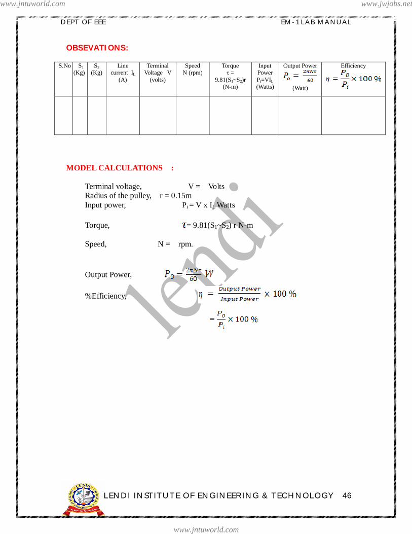
OBSEVATIONS:
S.No S1(Kg)
S2(Kg)
Linecurrent IL
(A)
TerminalVoltage V
(volts)
SpeedN (rpm)
Torque =
9.81(S1~S2)r(N-m)
InputPowerPi=VIL(Watts)
Output Power
(Watt)
Efficiency
MODEL CALCULATIONS :
Terminal voltage, V = Volts Radius of the pulley, r = 0.15m Input power, Pi = V x IL Watts
Torque, = 9.81(S1~S2) r N-m
Speed, N = rpm.
Output Power,
%Efficiency,
www.jntuworld.com
www.jntuworld.com
www.jwjobs.net

DEPT OF EEE EM-1 LAB MANUAL
LENDI INSTITUTE OF ENGINEERING & TECHNOLOGY 47
MODEL GRAPHS :
PRECAUTIONS :
1. Loose connections must be avoided to prevent from short-circuits.2. Starter should be operated gently and the brake should be slowly applied in steps to
avoid over loading.3. See that the drum of the pulley doesn t get much heated by pouring water.
www.jntuworld.com
www.jntuworld.com
www.jwjobs.net
DEPT OF EEE EM-1 LAB MANUAL
LENDI INSTITUTE OF ENGINEERING & TECHNOLOGY 48
RESULT:
CONCLUSION:
VIVA QUESTIONS:
1) Where are dc compound motors used?
2) Where are differentially compounded shunt motors used?
3) What may be the causes of sparking in a motor?
4) How can be the direction of rotation of motor be reversed in DC compoundmotor?
5) What is the purpose of using 4-point starter to start compound motor?
www.jntuworld.com
www.jntuworld.com
www.jwjobs.net

DEPT OF EEE EM-1 LAB MANUAL
LENDI INSTITUTE OF ENGINEERING & TECHNOLOGY 49
LOAD TEST OND.C.
COMPOUND GENERATOR
www.jntuworld.com
www.jntuworld.com
www.jwjobs.net

DEPT OF EEE EM-1 LAB MANUAL
LENDI INSTITUTE OF ENGINEERING & TECHNOLOGY 50
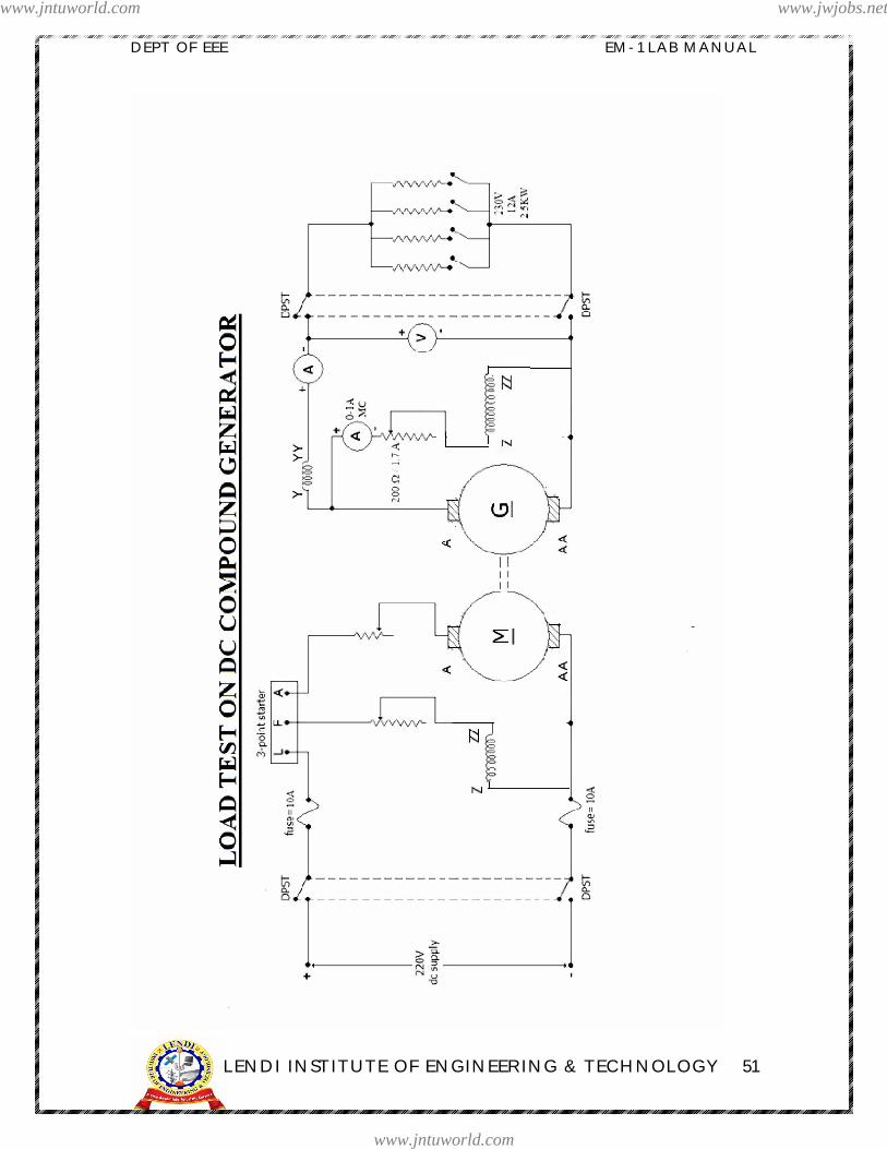
LOAD TEST ON DC COMPOUND GENERATOR
Experiment no:8
AIM: To determine the load characteristics of a DC compound generator.
NAME PLATE DETAILS:
Type DC Shunt Motor DC compoundGenerator
Ratings 3.0 HP 2 KW
Volts. 220 V DC 220 V DC
Current 12 A 12A
Exc. Volts. 220 V DC 220 V DC
Exc. Current 0.6A 0.7A
Duty S1 S1
Ins. Class B B
Speed 1500 rpm 1500 rpm
APPARATUS:
S.No. Name of Equipment Range Type Quantity
1 Voltmeter
2 Ammeter
3 Rheostat
4 Tachometer
5 Load box
www.jntuworld.com
www.jntuworld.com
www.jwjobs.net
DEPT OF EEE EM-1 LAB MANUAL
LENDI INSTITUTE OF ENGINEERING & TECHNOLOGY 51
www.jntuworld.com
www.jntuworld.com
www.jwjobs.net
DEPT OF EEE EM-1 LAB MANUAL
LENDI INSTITUTE OF ENGINEERING & TECHNOLOGY 52
THEORY: The external characteristics of a compound generator are shown in graph. In a
cumulatively compound generator with increase in load current the series field flux aidsthe shunt field flux. Depending upon the number of series field turns, the cumulativecompound generator may be under compounded, over compounded and flat compounded.Cumulative compound generators are more common because they can furnish almostconstant voltage from no load to full load.In differentially compound generator, with the increase of load, series field flux opposesshunt field flux and consequently the terminal voltage falls more rapidly, these are notdamaged by short circuit. In view of this, these types of generators may be used forwelding purposes, where sudden short circuit occurs every time the electric touches theworking part. The degree of compound can be controlled by connecting a suitable lowresistance called diverter in parallel with series field winding
PROCEDURE:1) Connect the circuit as shown in the circuit diagram.2) Keep the field and armature rheostats of motor and the field rheostat of the
generator in minimum, maximum and maximum positions respectively.3) Start the motor using a 3-point starter and there by the generator.
Run the motor to its rated speed by varying the armature and field rheostats of the motor and keep it constant 4) Adjust the shunt field rheostat of the generator to obtain rated voltage at no load.
5) Note down the no load terminal of the generator. 6) Apply the load in steps on the generator and for each load note down the corresponding field current, line current and terminal voltage. Then remove the load and switch off the supply
OBSERVATIONS:
SNo
Vt (volts) Ish(amps) IL(amps) Ia (amps) Eg (volts)
www.jntuworld.com
www.jntuworld.com
www.jwjobs.net

DEPT OF EEE EM-1 LAB MANUAL
LENDI INSTITUTE OF ENGINEERING & TECHNOLOGY 53
MODEL CALCULATIONS:
Vt = Ish = IL = Ia = IL + Ish Ra = Rse =Eg = Vt + IaRa + ILRse
PRECAUTIONS:1) Ensure that the armature rheostat is kept at the maximum position and the field
rheostat is kept at minimum position before switching on the supply.2) Speed must be maintained constant throughout the experiment.3) The tachometer should be kept in line with the shaft while measuring the speed.4) Ensure that the starter arm is at the extreme left position before switching on the
supply.
RESULT:
CONCLUSION:
IL, Ia (Amps)
ExternalCharacteristics
InternalCharacteristics
Vt, Eg(Volts)
www.jntuworld.com
www.jntuworld.com
www.jwjobs.net

DEPT OF EEE EM-1 LAB MANUAL
LENDI INSTITUTE OF ENGINEERING & TECHNOLOGY 54
VIVA QUESTIONS:1.How the compound generator operates?2.What is the application of cumulative compound wound generator?3.When the compound wound generator will be called as over compound?4.Explain the characteristics of all types of compound wound generators?
www.jntuworld.com
www.jntuworld.com
www.jwjobs.net
DEPT OF EEE EM-1 LAB MANUAL
LENDI INSTITUTE OF ENGINEERING & TECHNOLOGY 55
SEPARATION OF LOSSESIN D.C. SHUNT
MACHINE
www.jntuworld.com
www.jntuworld.com
www.jwjobs.net
DEPT OF EEE EM-1 LAB MANUAL
LENDI INSTITUTE OF ENGINEERING & TECHNOLOGY 56
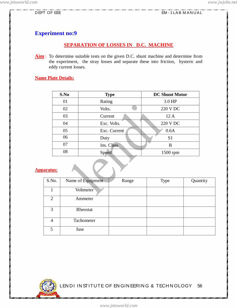
Experiment no:9
SEPARATION OF LOSSES IN D.C. MACHINE
Aim : To determine suitable tests on the given D.C. shunt machine and determine fromthe experiment, the stray losses and separate these into friction, hysteric andeddy current losses.
Name Plate Details:
S.No Type DC Shunt Motor01 Rating 3.0 HP02 Volts. 220 V DC03 Current 12 A04 Exc. Volts. 220 V DC05 Exc. Current 0.6A06 Duty S107 Ins. Class B08 Speed 1500 rpm
Apparatus:
S.No. Name of Equipment Range Type Quantity
1 Voltmeter
2 Ammeter
3 Rheostat
4 Tachometer
5 fuse
www.jntuworld.com
www.jntuworld.com
www.jwjobs.net

DEPT OF EEE EM-1 LAB MANUAL
LENDI INSTITUTE OF ENGINEERING & TECHNOLOGY 57
www.jntuworld.com
www.jntuworld.com
www.jwjobs.net
DEPT OF EEE EM-1 LAB MANUAL
LENDI INSTITUTE OF ENGINEERING & TECHNOLOGY 58
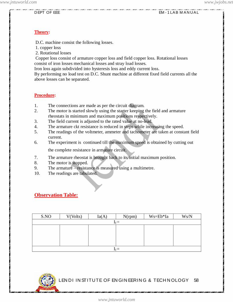
Theory:
D.C. machine consist the following losses. 1. copper loss 2. Rotational losses Copper loss consist of armature copper loss and field copper loss. Rotational lossesconsist of iron losses mechanical losses and stray load losses.Iron loss again subdivided into hysteresis loss and eddy current loss.By performing no load test on D.C. Shunt machine at different fixed field currents all theabove losses can be separated.
Procedure:
1. The connections are made as per the circuit diagram.2. The motor is started slowly using the starter keeping the field and armature
rheostats in minimum and maximum positions respectively.3. The field current is adjusted to the rated value at no-lead.4. The armature ckt resistance is reduced in steps while increasing the speed.5. The readings of the voltmeter, ammeter and tachometer are taken at constant field
current.6. The experiment is continued till the maximum speed is obtained by cutting out
the complete resistance in armature circuit.7. The armature rheostat is brought back to its initial maximum position.8. The motor is stopped.9. The armature resistance is measured using a multimetre.10. The readings are tabulated.
Observation Table:
S.NO V(Volts) Ia(A) N(rpm) Ws=Eb*Ia Ws/NIf =
If =
www.jntuworld.com
www.jntuworld.com
www.jwjobs.net

DEPT OF EEE EM-1 LAB MANUAL
LENDI INSTITUTE OF ENGINEERING & TECHNOLOGY 59
Model Graph:
Ws/N
N
The plot of Ws/N versus N is to plotted to find out the intercept and slopes.
Precautions:
1. The rheostats are to be kept in proper positions while starting the motor.2. Loose connections are to be avoided.3. The field current is to be maintained constant for a particular excitation though
the speeds are varied, by using the armature rhestat.
Results:
Conclusions:
www.jntuworld.com
www.jntuworld.com
www.jwjobs.net

DEPT OF EEE EM-1 LAB MANUAL
LENDI INSTITUTE OF ENGINEERING & TECHNOLOGY 60
VIVA QUESTIONS:
1. What are the losses in a DC machine?2. Why is the field copper loss negligible at no load?3. Why does the armature resistance increase when the motor is running?4. How can the mechanical losses be reduced?5. How can the core losses be minimized?6.What will happen to the losses in a dc motor when its supply voltage is: a) doubled b) halved?
www.jntuworld.com
www.jntuworld.com
www.jwjobs.net

DEPT OF EEE EM-1 LAB MANUAL
LENDI INSTITUTE OF ENGINEERING & TECHNOLOGY 61
FIELDS TEST ON D.C.SERIES MACHINES
www.jntuworld.com
www.jntuworld.com
www.jwjobs.net

DEPT OF EEE EM-1 LAB MANUAL
LENDI INSTITUTE OF ENGINEERING & TECHNOLOGY 62
Experiment no:10
FIELDS TEST ON D.C. SERIES MACHINES
Aim : To perform FIELD test on a given D.C series motor generator set and determine the efficiency of both motor and generator
Name Plate Details:
Type DC Series Motor DC Series Generator
Ratings 3.0 HP 2 KW
Volts. 220 V DC 220 V DC
Current 12 A 12A
Exc. Volts. 220 V DC 220 V DC
Exc. Current 0.6A 0.7A
Duty S1 S1
Ins. Class B B
Speed 1500 rpm 1500 rpm
Apparatus:
S.No. Name of Equipment Range Type Quantity
1 Voltmeter
2 Ammeter
3 Rheostat
4 Tachometer
5 Fuse
www.jntuworld.com
www.jntuworld.com
www.jwjobs.net

DEPT OF EEE EM-1 LAB MANUAL
LENDI INSTITUTE OF ENGINEERING & TECHNOLOGY 63
www.jntuworld.com
www.jntuworld.com
www.jwjobs.net

DEPT OF EEE EM-1 LAB MANUAL
LENDI INSTITUTE OF ENGINEERING & TECHNOLOGY 64
Theory: Small series machines can be tested by brake test similar to shunt machines, but the largeseries machines cannot be tested by Swinburne s test in the same way as shunt machines,because series motors cannot be run on no load due to dangerous high speed. In view ofthis field test is quite suitable for D.C. series machines In this test two similar D.C. machines are required. Thesetwo machines are mechanically coupled together and their fields are connected in seriesin order to make iron losses of both machines equal. One of the machines operates as amotor and drives the other machine operating as a separately excited generator.
PROCEDURE:
1. Connect the circuit as shown in the circuit diagram.2. Start the DC series motor using 2-point starter and adjust its speed with the help
of Rheostat to the rated speed of generator.3. Note down the reading of voltage generated across the armature of generator at
the corresponding load current.4. Now switch on the load in steps and note down the corresponding readings of
load current and terminal voltage maintaining at rated speed.5. The procedure is repeated until the rated current is reached.6. Reduce the load to zero and switch off the load.7. Make all the Rheostats to its initial positions and then switch off the DC Supply.
OBSERVATIONS:
S No Terminal Voltage, Vt (Volts) Load current, IL (Amp) Eg(Volts)
MODEL CALCULATIONS:
Let supply voltage=V voltsMotor input current=I1Terminal voltage of generator=V2Load current of generator= I2Armature resistance of each machine=RaSeries field resistance of each machine=RseInput to the total set=VI1Output power = V2I2Total losses of the set, PT= VI1-V2I2Series field and armature copper losses of motor=I1
2 (Ra+Rse)Ser Series field and armature copper losses of generator = I1
2Rse+I22Ra
www.jntuworld.com
www.jntuworld.com
www.jwjobs.net

DEPT OF EEE EM-1 LAB MANUAL
LENDI INSTITUTE OF ENGINEERING & TECHNOLOGY 65
Total copper losses of the set, Pc= I12(Ra+2Rse)+I2
2RaStray power losses for the set = PT - Pc
Stray power losses per machine, Ps=
MOTOR EFFICIENCY:
Motor input = V1I1 Motor losses = I1
2(Ra+Rse)+PS Motor output = V1I1- I1
2(Ra+Rse)-PS
Motor efficiency =
GENERATOR EFFICIENCY:
Generator output = V2I2 Generator losses = I2
2Ra+I12Rse+PS
Generator input = V2I2+I22Ra+I1
2Rse+PS
Generator efficiency =
GRAPHS :1.Output VS Efficiency (of generator)2. Output VS Efficiency (of motor)
PRECAUTIONS:
2. The switch S is closed only when the voltmeter across the switch reads zero.2. Loose connections are to be avoided.3. The rheostats are to be kept at proper positions while starting the motor.4. The readings of all the metres are to be noted down without any error.
RESULT:
CONCLUSIONS:
www.jntuworld.com
www.jntuworld.com
www.jwjobs.net
DEPT OF EEE EM-1 LAB MANUAL
LENDI INSTITUTE OF ENGINEERING & TECHNOLOGY 66
VIVA QUESTIONS:1. What is the advantage of fields test?
2. How the direction of rotation of DC series motor can be reversed?
3. If a DC motor is connected across AC supply what happens?
4. What type of motor will be used for traction purpose and why?
5. Why the stator is not laminated in D.C. machines?
6. Difference between two point starter and three point starter?
www.jntuworld.com
www.jntuworld.com
www.jwjobs.net