Embed Size (px)
Citation preview
© 2018 IBRACON
Volume 11, Number 7 (February 2018) p. 163 – 182 • ISSN 1983-4195http://dx.doi.org/10.1590/S1983-41952018000100009
Combined axial and flexural loads in short reinforced concrete columns in fire: ultimate limit state curves using 500 °C isotherm method
Flexão composta oblíqua em pilares curtos de concreto armado em situação de incêndio: curvas do estado – limite último pelo método da isoterma de 500 °C
a Universidade de São Paulo, Escola Politécnica, Departamento de Engenharia de Estruturas e Geotécnica, São Paulo, SP, Brasil.
Received: 24 Jan 2016 • Accepted: 20 Jun 2017 • Available Online: 15 Feb 2018
J. S. SUAZNABAR a
V. P. SILVA a
Abstract
Resumo
Ultimate limit state curves of short reinforced concrete columns in fire situation are going to be presented in this paper. The authors created a code developed in Matlab. It makes a discretization of the cross sections of the columns and calculates the equilibrium integrals of them. The curves were plotted with the code considering the 500 °C isotherm method.
Keywords: reinforced concrete columns, fire situacion.
Curvas envoltórias correspondentes ao estado – limite último de pilares curtos de concreto armado em situação de incêndio serão apresentadas neste artigo. Os autores criaram um código desenvolvido no programa Matlab. Esse código realiza uma discretização da seção transversal dos pilares e o cálculo numérico das integrais de equilíbrio. As curvas foram representadas graficamente com o código considerando o método da isoterma de 500 °C.
Palavras-chave: pilares, concreto armado, incêndio, flexão composta, isoterma de 500 ºC.

164 IBRACON Structures and Materials Journal • 2018 • vol. 11 • nº 1
Combined axial and flexural loads in short reinforced concrete columns in fire: ultimate limit state curves using 500 °C isotherm method
1. Introduction
Combined axial and flexural loads in short reinforced concrete columns in fire situation is a very new subject studied internation-ally [1] and [2]. Several aspects should be considered in order to
determine the safety of these structural elements, among others, the temperature field in the cross-section and the non-linearity of the materials. Consideration of these aspects increases the level of difficulty. As an option, a strategy is to define maximum values for strains and the pivot diagrams (Figure 1), and to apply them to create the ultimate limit state curves and surfaces, also called interaction curves and surfaces, that allow to verify the safety of the columns. They are function of, among others, the constitutive laws of concrete and reinforcing steel, the cross-section geometry
and the maximum strains. There is an extensive bibliography avail-able, such as abacuses and simplified methods [3], [4], and more advanced numerical methods, for columns at room temperature [5]. But there is a smaller quantity for fire situation, among others, advanced software DIANA, ABAQUS, ANSYS and SAFIR.
In Figure 1:εcu: Strain conventionally corresponding to the ultimate limit state of the most compressed concrete fiber of a fully compressed cross-section.εc2: Strain conventionally corresponding to the ultimate limit state of the less compressed concrete fiber of a fully compressed cross-section.εsu: Strain conventionally corresponding to the ultimate limit state of the tensioned reinforcing steel.εyd: Strain corresponding to the beginning of the yield of the rein-forcing steel.h: Cross-section high.In fire situation, these interaction curves are function (besides the mentioned variables) of the time. In order to generate these inter-action curves in fire situation, two strategies can be considered [1], those that consider the moment-curvature relationship and those that consider the boundary strains according to pivot diagrams. Those pivot diagrams in fire situation are different of those used at room temperature, which should vary according to the tempera-ture. The pivot diagrams have been studied in [6], they are present-ed in the Figure 2 and are part of more advanced researches in the same research group of the authors. However, using these do-mains implies a greater computational effort and allows the study of straight but not oblique composite bending of the columns [7].In Figure 2:
Figure 1Pivot diagrams at room temperature
Figure 2Pivot diagrams in fire situation
165IBRACON Structures and Materials Journal • 2018 • vol. 11 • nº 1
J. S. SUAZNABAR | V. P. SILVA
εcu,Ɵ: Strain conventionally corresponding to the ultimate limit state of the compressed concrete at Ɵ temperature. εsu,Ɵ: Strain conventionally corresponding to the ultimate limit state of the tensioned reinforcing steel at Ɵ temperature.εtot,i: Total strain in a point i of the fully compressed concrete cross-section.The objective of this paper is to present a computational code developed in MATLAB [8] which, through numerical methods, ac-curately calculates forces and moments, strains and interaction curves for short columns of reinforced concrete in fire situation. It is considered the hypotheses of the 500 °C isotherm method to generate the interaction curves.
2. Method of the 500 °C isotherm
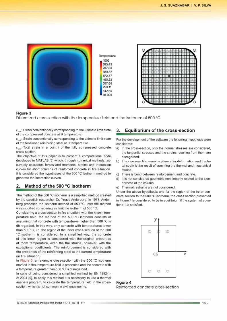
The method of the 500 °C isotherm is a simplified method created by the swedish researcher Dr. Yngve Anderberg. In 1978, Ander-berg proposed the isotherm method of 550 °C, later the method was modified considering as limit the isotherm of 500 °C.Considering a cross section in fire situation, with the known tem-perature field, the method of the 500 °C isotherm consists of assuming that concrete with temperatures higher than 500 °C is disregarded. In this way, only concrete with temperatures lower than 500 °C, i.e. the region of the inner cross-section at the 500 °C isotherm, is considered. In a simplified way, the concrete of this inner region is considered with the original properties at room temperature, even the the strains, however, with the exceptional coefficients. The reinforcement is considered with the properties of the reinforcing steel at the current temperature (in fire situation).In Figure 3, an example cross-section with the 500 °C isotherm marked in the temperature field is presented and the concrete with a temperature greater than 500 °C is disregarded.In spite of being considered a simplified method by EN 1992-1-2: 2004 [9], to apply this method it is necessary to use a thermal analysis program, to calculate the temperature field in the cross-section, which is not common in civil engineering.
3. Equilibrium of the cross-section
For the development of the software the following hypothesis were considered:a) In the cross-section, only the normal stresses are considered,
the tangential stresses and the strains resulting from them are disregarded.
b) The cross-section remains plane after deformation and the to-tal strain is the result of summing the thermal and mechanical strains.
c) There is bond between reinforcement and concrete.d) It is not considered geometric non-linearity related to the slen-
derness of the column.e) Thermal restrains are not considered.Under the above hypothesis and for the region of the inner con-crete section to the 500 ºC isotherm, the cross section presented in Figure 4 is considered to be in equilibrium if the system of equa-tions 1 is satisfied.
Figure 3Discretized cross-section with the temperature field and the isotherm of 500 °C
Figure 4Reinforced concrete cross-section
166 IBRACON Structures and Materials Journal • 2018 • vol. 11 • nº 1
Combined axial and flexural loads in short reinforced concrete columns in fire: ultimate limit state curves using 500 °C isotherm method
In Figure 4:CG: Geometric center of the cross-section.
(1)In the system of Equations 1:
=
x
y
NS M
M
1 =
Z yx
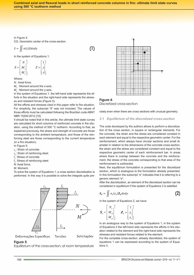
Where:N : Axial force.Mx : Moment around the x-axis.My : Moment around the y-axis.In the system of Equations 1, the left-hand side represents the ef-forts in fire situation and the right-hand side represents the stress-es and resistant forces (Figure 5).All the efforts and stresses cited in this paper refer to fire situation. For simplicity, the subscript “θ” was not included. The values of those efforts must be calculated following the Brazilian code ABNT NBR 15200:2012 [10].It should be noted that in this article, the ultimate limit state curves are calculated for short columns of reinforced concrete in fire situ-ation, using the method of 500 °C isotherm. According to that, as explained previously, the stress and strength of concrete are those corresponding to the ambient temperature, and those of the rein-forcing steel are those corresponding to the current temperature (in a fire situation).In Figure 5:εc: Strain of concrete.εs: Strain of reinforcing steel.fc: Stress of concrete.fs: Stress of reinforcing steel.N: Axial force.M: Moment.To solve the system of Equations 1, a cross section discretization is performed. In this way it is possible to solve the integrals quite pre-
cisely even when there are cross sections with unusual geometry.
3.1 Equilíbrium of the discretized cross-section
The code developed by the authors allows to perform a discretiza-tion of the cross section, in square or rectangular elements. For the concrete, the strain and the stress are considered constant in each element and equal to the respective geometric center. For the reinforcement, which always have circular sections and small di-ameter in relation to the dimensions of the concrete cross-section, the strain and the stress are considered constant and equal to the respective geometric center of each reinforcement bar. In areas where there is overlap between the concrete and the reinforce-ment, the stress of the concrete corresponding to that area of the reinforcement is subtracted.Next, the equilibrium formulation is presented for the discretized section, which is analogous to the formulation already presented. In this formulation the subscript “e” indicates that it is referring to a generic element “e”.After the discretization, an element of the discretized section can be considered in equilibrium if the system of Equations 2 is satisfied.
(2)In the system of Equations 2, we have:
=
e
xe
ye
NMM
eS 1
=
e
e
yx
eZ
In an analogous way to the system of Equations 1, in the system of Equations 2 the left-hand side represents the efforts in fire situ-ation related to the element and the right-hand side represents the stresses and resistant forces related to the element.For the complete cross-section, already discretized, the system of equations 1 can be expressed according to the system of Equa-tions 3.
Figure 5Equilibrium of the cross-section, at room temperature
Figure 6Discretized cross-section
167IBRACON Structures and Materials Journal • 2018 • vol. 11 • nº 1
J. S. SUAZNABAR | V. P. SILVA
(3)
In system of Equations 3:N : Axial force.Mx : Moment around the x-axis.My : Moment around the y-axis.σci : Stress of the concrete element i.σsi : Stress of the reinforcing steel element i.εci : Strain of the concrete element i.εsi : Strain of the reinforcing steel element i.Aci : Area of the concrete element i.Asi : Area of the reinforcing steel element i.xci : Coordinate x of the geometric center of the concrete element i.yci : Coordinate y of the geometric center of the concrete element i.xsi : Coordinate x of the geometric center of the reinforcing steel element i.It should be noted that the stress distribution is considered con-stant in the cross section of each element, therefore adequate dis-cretization is required to obtain a good stress distribution in the cross section of the column.
4. Ultimate limit state curves
Under the assumptions given above, for a set of efforts in fire situ-ation, the code applies strain fields to the cross-section and evalu-ates the system of Equations 3. This process is performed in an iterative way until the equilibrium is satisfied. However, it is simpler to apply the conventional strains of the ultimate limit state and to calculate the stresses related to these strains.To generate the ultimate limit state curves, it is sufficient to define
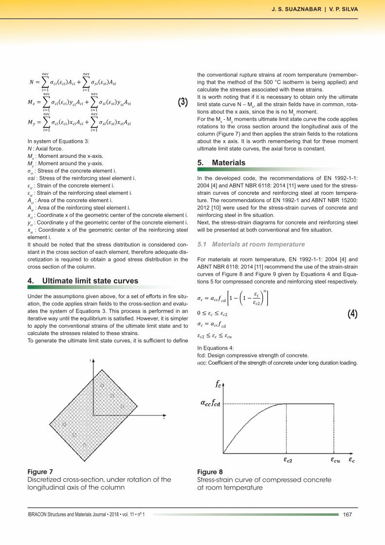
the conventional rupture strains at room temperature (remember-ing that the method of the 500 °C isotherm is being applied) and calculate the stresses associated with these strains.It is worth noting that if it is necessary to obtain only the ultimate limit state curve N – Mx, all the strain fields have in common, rota-tions about the x axis, since the is no My moment.For the Mx - My moments ultimate limit state curve the code applies rotations to the cross section around the longitudinal axis of the column (Figure 7) and then applies the strain fields to the rotations about the x axis. It is worth remembering that for these moment ultimate limit state curves, the axial force is constant.
5. Materials
In the developed code, the recommendations of EN 1992-1-1: 2004 [4] and ABNT NBR 6118: 2014 [11] were used for the stress-strain curves of concrete and reinforcing steel at room tempera-ture. The recommendations of EN 1992-1 and ABNT NBR 15200: 2012 [10] were used for the stress-strain curves of concrete and reinforcing steel in fire situation.Next, the stress-strain diagrams for concrete and reinforcing steel will be presented at both conventional and fire situation.
5.1 Materials at room temperature
For materials at room temperature, EN 1992-1-1: 2004 [4] and ABNT NBR 6118: 2014 [11] recommend the use of the strain-strain curves of Figure 8 and Figure 9 given by Equations 4 and Equa-tions 5 for compressed concrete and reinforcing steel respectively.
(4)
In Equations 4:fcd: Design compressive strength of concrete.αcc: Coefficient of the strength of concrete under long duration loading.
Figure 7Discretized cross-section, under rotation of the longitudinal axis of the column
Figure 8Stress-strain curve of compressed concrete at room temperature

168 IBRACON Structures and Materials Journal • 2018 • vol. 11 • nº 1
Combined axial and flexural loads in short reinforced concrete columns in fire: ultimate limit state curves using 500 °C isotherm method
(5)
In Equations 5:Es : Modulus of elasticity of reinforcing steel.fyd : Design strength of reinforcing steel.
5.2 Materialsinfiresituation
For the materials in fire situation, EN 1992-1-2:2004 [9] and ABNT NBR 15200:2012 [10] recommend the stress-strain curves of Fig-ure 10 and Figure 11 given by Equation 6 and Equations 7 for compressed concrete and reinforcing steel respectively.
(6)
(7)
In Equations 6 and 7:
1 Average humidity estimated for the city of Foz do Iguaçu (Brazil).2 Average value based on report from IPCC [27].
Figure 9Stress-strain curve of reinforcing steel at room temperature
Figure 10Stress-strain curve of compressed concrete in fire situation
Figure 11Stress-strain curve of reinforcing steel in fire situation
Figure 12Stress-strain curves of concrete varying with temperature
169IBRACON Structures and Materials Journal • 2018 • vol. 11 • nº 1
J. S. SUAZNABAR | V. P. SILVA
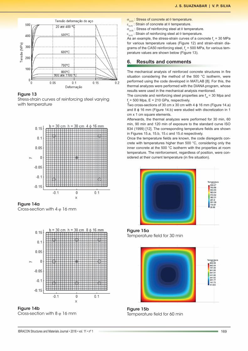
σ(c,θ) : Stress of concrete at θ temperature.ε(c,θ) : Strain of concrete at θ temperature.σ(s,θ) : Stress of reinforcing steel at θ temperature.ε(s,θ) : Strain of reinforcing steel at θ temperature.As an example, the stress-strain curves of a concrete fc = 30 MPa for various temperature values (Figure 12) and strain-strain dia-grams of the CA50 reinforcing steel, fy = 500 MPa, for various tem-perature values are shown below (Figure 13).
6. Results and comments
The mechanical analysis of reinforced concrete structures in fire situation considering the method of the 500 °C isotherm, were performed using the code developed in MATLAB [8]. For this, the thermal analyzes were performed with the DIANA program, whose results were used in the mechanical analysis mentioned.The concrete and reinforcing steel properties are fck = 30 Mpa and fy = 500 Mpa, E = 210 GPa, respectively.Two cross-sections of 30 cm x 30 cm with 4 ϕ 16 mm (Figure 14.a) and 8 ϕ 16 mm (Figure 14.b) were studied with discretization in 1 cm x 1 cm square elements.Afterwards, the thermal analyzes were performed for 30 min, 60 min, 90 min and 120 min of exposure to the standard curve ISO 834 (1999) [12]. The corresponding temperature fields are shown in Figures 15.a, 15.b, 15.c and 15.d respectively.Once the temperature fields are known, the code disregards con-crete with temperatures higher than 500 °C, considering only the inner concrete at the 500 °C isotherm with the properties at room temperature. The reinforcement, regardless of position, were con-sidered at their current temperature (in fire situation).
Figure 13Stress-strain curves of reinforcing steel varying with temperature
Figure 14aCross-section with 4 ϕ 16 mm
Figure 14bCross-section with 8 ϕ 16 mm
Figure 15bTemperature field for 60 min
Figure 15aTemperature field for 30 min
170 IBRACON Structures and Materials Journal • 2018 • vol. 11 • nº 1
Combined axial and flexural loads in short reinforced concrete columns in fire: ultimate limit state curves using 500 °C isotherm method
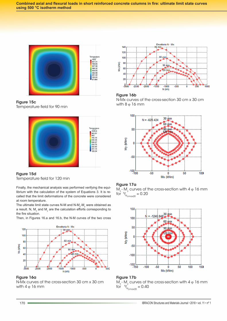
Finally, the mechanical analysis was performed verifying the equi-librium with the calculation of the system of Equations 3. It is re-called that the limit deformations of the concrete were considered at room temperature.The ultimate limit state curves N-M and N-Mx-My were obtained as a result. N, Mx and My are the calculation efforts corresponding to the fire situation.Then, in Figures 16.a and 16.b, the N-M curves of the two cross
Figure 15cTemperature field for 90 min
Figure 15dTemperature field for 120 min
Figure 16aN-Mx curves of the cross-section 30 cm x 30 cm with 4 ϕ 16 mm
Figure 16bN-Mx curves of the cross-section 30 cm x 30 cm with 8 ϕ 16 mm
Figure 17bMx - My curves of the cross-section with 4 ϕ 16 mm for N⁄Ncmax20
= 0.40
Figure 17aMx - My curves of the cross-section with 4 ϕ 16 mm for N⁄Ncmax20
= 0.20
171IBRACON Structures and Materials Journal • 2018 • vol. 11 • nº 1
J. S. SUAZNABAR | V. P. SILVA
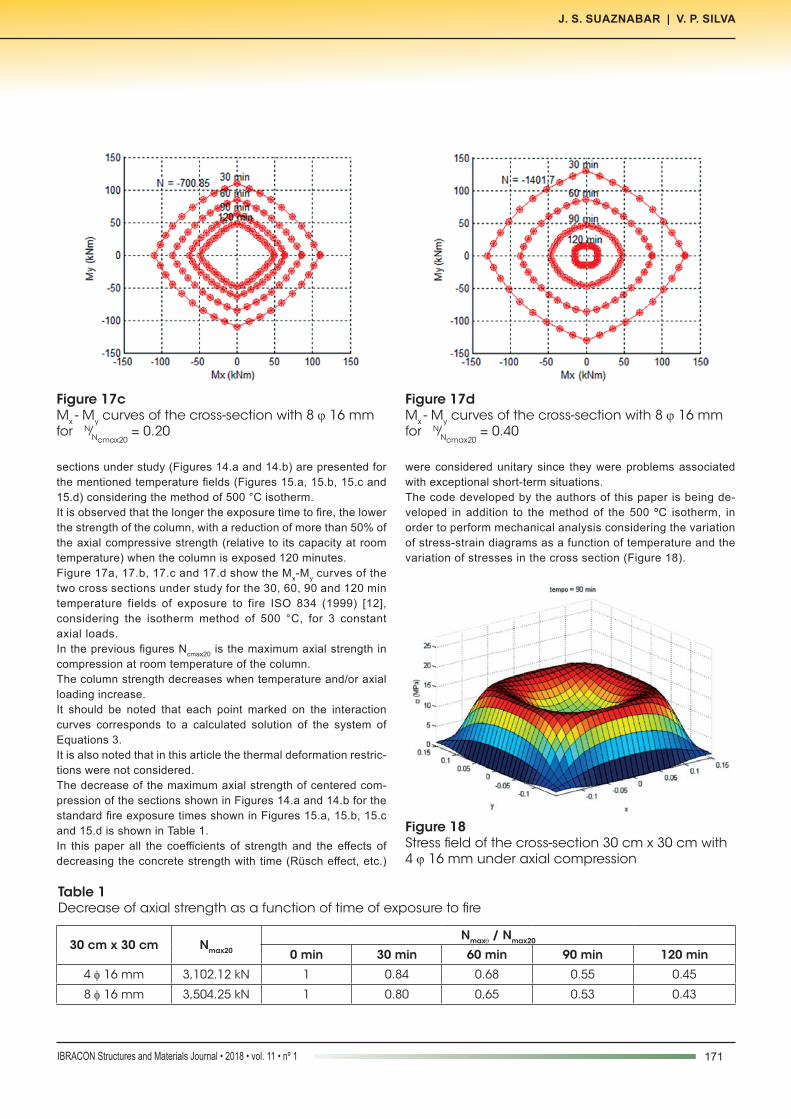
sections under study (Figures 14.a and 14.b) are presented for the mentioned temperature fields (Figures 15.a, 15.b, 15.c and 15.d) considering the method of 500 °C isotherm.It is observed that the longer the exposure time to fire, the lower the strength of the column, with a reduction of more than 50% of the axial compressive strength (relative to its capacity at room temperature) when the column is exposed 120 minutes.Figure 17a, 17.b, 17.c and 17.d show the Mx-My curves of the two cross sections under study for the 30, 60, 90 and 120 min temperature fields of exposure to fire ISO 834 (1999) [12], considering the isotherm method of 500 °C, for 3 constant axial loads.In the previous figures Ncmax20 is the maximum axial strength in compression at room temperature of the column.The column strength decreases when temperature and/or axial loading increase.It should be noted that each point marked on the interaction curves corresponds to a calculated solution of the system of Equations 3.It is also noted that in this article the thermal deformation restric-tions were not considered.The decrease of the maximum axial strength of centered com-pression of the sections shown in Figures 14.a and 14.b for the standard fire exposure times shown in Figures 15.a, 15.b, 15.c and 15.d is shown in Table 1.In this paper all the coefficients of strength and the effects of decreasing the concrete strength with time (Rüsch effect, etc.)
were considered unitary since they were problems associated with exceptional short-term situations.The code developed by the authors of this paper is being de-veloped in addition to the method of the 500 ºC isotherm, in order to perform mechanical analysis considering the variation of stress-strain diagrams as a function of temperature and the variation of stresses in the cross section (Figure 18).
Figure 17cMx - My curves of the cross-section with 8 ϕ 16 mm for N⁄Ncmax20
= 0.20
Figure 17dMx - My curves of the cross-section with 8 ϕ 16 mm for N⁄Ncmax20
= 0.40
Table 1Decrease of axial strength as a function of time of exposure to fire
30 cm x 30 cm Nmax20
Nmaxθ / Nmax20
0 min 30 min 60 min 90 min 120 min
4 φ 16 mm 3,102.12 kN 1 0.84 0.68 0.55 0.45
8 φ 16 mm 3,504.25 kN 1 0.80 0.65 0.53 0.43
Figure 18Stress field of the cross-section 30 cm x 30 cm with 4 ϕ 16 mm under axial compression
172 IBRACON Structures and Materials Journal • 2018 • vol. 11 • nº 1
Combined axial and flexural loads in short reinforced concrete columns in fire: ultimate limit state curves using 500 °C isotherm method
7. Conclusions
In order to perform numerical modeling of short columns of rein-forced concrete in a fire situation, the use of the 500 °C isotherm method proved to be a suitable strategy.The computational code developed for this article was able to gen-erate ultimate limit state curves using the method of the 500 °C isotherm, combined with a method that solves the integrals and systems of equations using a discretization of the cross section.As expected, the results showed that the longer the exposure time to fire the higher the temperature in the cross section, therefore the lower the strength of the column. The results also showed that the higher the compressive force on the column, the shorter the time it reaches the ultimate limit state.Finally, it is emphasized that the mathematics used to study the phenomena studied involves systems of equations with integral of non-linear equations. The resolution of these systems of equa-tions was possible using approximate methods with discretization of the cross section considered in the academic environment as advanced methods.
8. Acknowledgments
The authors thank CAPES “Coordenação de Aperfeiçoamento de Pessoal de Nível Superior”, CNPq “Conselho Nacional de Pes-quisa e Desenvolvimento Científico” and FAPESP “Fundação de Amparo à Pesquisa do Estado de São Paulo”.
9. References
[1] FÉDÉRATION INTERNATIONALE DU BÉTON. Fire design of concrete structures – structural behavior and assessment. State of art report. Lausanne, 2008.
[2] FÉDÉRATION INTERNATIONALE DU BÉTON. Fire de-sign of concrete structures – materials, structures and mod-elling. State of art report. Lausanne, 2007.
[3] MESEGUER, A. G.; CABRÉ, F. M.; PORTERO, J. C. A. Jimenez Montoya – Hormigón Armado. Gustavo Gili, Barce-lona, España, 2009.
[4] EUROPEAN COMMITTEE FOR STANDARIZATION. EN 1992-1-1. Eurocode 2: Design of concrete structures – part 1.2 General rules and rules for buildings. Brussels: CEN, 2004.
[5] RODRIGUEZ, J.A.; ARISTIZABAL, O.D. Biaxial Interaction Diagrams for Short RC Columns of Any Cross Section. Jour-nal of Structural Engineering. v. 125, p. 672-683, 1999.
[6] SUAZNABAR, J.S.; SILVA, V.P.; PIERIN, I. Estudo dos Domínios de Deformação em Seções Transversais de Concreto Armado em Situação de Incêndio. 56 Congresso Brasileiro do Concreto. Natal, 2014.
[7] SUAZNABAR, J.S.; SILVA, V.P. Flexão composta de pilares curtos de concreto armado sob incêndio não simétrico. 3 Congresso Ibero-Latino-Americano Sobre Segurança Con-tra Incêndios. Porto Alegre, 2015.
[8] SUAZNABAR, J.S.; SILVA, V.P. Code for combined axial and flexural load on short RC columns: failure surfaces. XXXVI Jornadas Sudamericanas de Ingeniería Estructural. Monte-video, 2014.
[9] EUROPEAN COMMITTEE FOR STANDARIZATION. EN 1992-1-2. Eurocode 2: Design of concrete structures – part 1.2 General rules – structural fire design. Brussels: CEN, 2004.
[10] ASSOCIAÇÃO BRASILEIRA DE NORMAS TÉCNICAS. NBR 15200: Projeto de estruturas de concreto em situação de incêndio. Rio de Janeiro, 2012.
[11] ASSOCIAÇÃO BRASILEIRA DE NORMAS TÉCNICAS. NBR 6118: Projeto de estruturas de concreto: Procedimento. Rio de Janeiro, 2014.
[12] INTERNATIONAL ORGANIZATION FOR STANDARIZA-TION ISSO 834-1:1999(E). Fire-resistance tests – Elements of building construction – Part 1: General requirements. Ginebra, 1999.


![PILAR - DIAGRAMA DE INTERAÇÃO FORÇA … - DIAGRAMA DE INTERAÇÃO FORÇA NORMAL E MOMENTO FLETOR - FLEXÃO OBLÍQUA [MONTOYA] Fernando Musso Junior musso@npd.ufes.br Estruturas](https://img.document.onl/doc/110x75/5c13401409d3f2b87d8c79d3/pilar-diagrama-de-interacao-forca-diagrama-de-interacao-forca-normal-e.jpg)


![PERSPECTIVA OBLÍQUA [Modo de Compatibilidade]](https://img.document.onl/doc/110x75/587222fb1a28ab50218b9c3b/perspectiva-obliqua-modo-de-compatibilidade.jpg)