Embed Size (px)
Citation preview
PONTIFÍCIA UNIVERSIDADE CATÓLICA DO RIO GRANDE DO SUL FACULDADE DE ODONTOLOGIA
PROGRAMA DE PÓS-GRADUAÇÃO EM ODONTOLOGIA NÍVEL: DOUTORADO
ÁREA DE CONCENTRAÇÃO: PRÓTESE DENTÁRIA
AVALIAÇÃO DA PRECISÃO DOS MODELOS DE GESSO OBTIDOS POR
DIFERENTES TÉCNICAS DE MOLDAGEM PARA PRÓTESES MÚLTIPLAS
IMPLANTO SUPORTADAS
ANNE BUSS BECKER
PORTO ALEGRE
2014

2
ANNE BUSS BECKER
AVALIAÇÃO DA PRECISÃO DOS MODELOS DE GESSO OBTIDOS POR
DIFERENTES TÉCNICAS DE MOLDAGEM PARA PRÓTESES MÚLTIPLAS
IMPLANTO SUPORTADAS
Tese apresentada ao Programa de Pós-Graduação em Odontologia da Faculdade de Odontologia da Pontifícia Universidade Católica do Rio Grande do Sul como requisito para obtenção do titulo de Doutor em Odontologia, na área de concentração de Prótese Dentária.
ORIENTADOR: Prof. Dr. HUGO MITSUO SILVA OSHIMA
PORTO ALEGRE 2014

3
ANNE BUSS BECKER
AVALIAÇÃO DA PRECISÃO DOS MODELOS DE GESSO OBTIDOS POR
DIFERENTES TÉCNICAS DE MOLDAGEM PARA PRÓTESES MÚLTIPLAS
IMPLANTO SUPORTADAS
Linha de Pesquisa: Técnicas e Aparelhos em Odontologia Tese apresentada ao Programa de Pós-Graduação em Odontologia da Faculdade de Odontologia da Pontifícia Universidade Católica do Rio Grande do Sul como requisito para obtenção do titulo de Doutor em Odontologia, na área de concentração de Prótese Dentária.
BANCA EXAMINADORA:
Profª Drª Regênio Mahfuz Herbstrith Segundo
Prof Dr Claudio Figueiró
Profª Drª Leticia Borges Jacques
Prof Dr Eduardo Gonçalves Mota

4
AGRADECIMENTOS

5
AGRADECIMENTOS
A Deus pela vida, fé, caminhos, esperanças. A fé em Deus nos faz crer no incrível, ver o
invisível e realizar o impossível.
Aos meus pais Carlos Celeste Lena Becker (in memoriam) e Maria Tereza Becker,
obrigado pelo dom da vida, pelas lições de amor, pela paciência, carinho, amor incondicional.
Ao meu esposo Carlos Alexandre Souza Bier, pelo apoio incondicional para que
continuasse me aperfeiçoando, pelo exemplo de pessoa, pai, professor.
Aos meus filhos Lucca Becker Bier e Clara Becker Bier, agradeço por me ensinarem a ser
uma pessoa melhor a cada momento. Lucca obrigado por eu ter graça de viver com esta pessoa
tão amável, carinhosa, cheia de ternura. Clara hoje você faz parte do nosso sonho, logo estará em
nossos braços.
Aos meus irmãos Leandro Buss Becker e Cristiane Buss Becker obrigado pelo
companheirismo, apoio e experiências trocadas durante todos estes anos. Leandro você é um
exemplo de pessoa, pesquisador e professor. Crika admiro sempre tua alegria, persistência e
entusiasmo.
Ao meu orientador Prof. Dr. Hugo Mitsuo Silva Oshima, que me acolheu, como aluna,
colega. Pela paciência e experiências compartilhadas.

6
A coordenadora do Programa de Pós Graduação da PUCR, Prof. Dra. Ana Maria Sphor,
pelas experiências compartilhadas, por sua dedicação e amor à causa Acadêmica.
Aos colegas de Doutorado da PUCRS pelos inúmeras experiências compartilhadas.
Aos meus colegas da UNIFRA, pelo companheirismo, experiências compartilhadas.
Obrigada a coordenadora Ana Maria Chagas por ter permitido que eu continuasse meus estudos
A Pontifícia Universidade Católica (PUCRS), por ter possibilitado o acesso a este
programa de Pós Graduação.
Ao Programa de Pós Graduação em Ciências Odontologicas da Universidade Federal de
Santa Maria, UFSM, por ter permitido a utilização da lupa estereomicroscopica.
Ao Prof Dr. Carlos Heitor Cunha Moreira pelo auxilio na análise estatística dos
resultados.

7
RESUMO

8
RESUMO
O objetivo deste estudo foi avaliar a precisão dos modelos de gesso sobre implantes
obtidos por meio da técnica de moldagem de arrasto, na qual utiliza transferentes quadrados,
utilizando diferentes materiais para união dos transferentes por meio de dois modelos
experimentais in vitro.
Inicialmente avaliou-se a precisão dos modelos de gesso obtidos por meio de duas
diferentes técnicas de moldagem: Grupo 1 – Moldagem de arrasto sem união dos transferentes e
Grupo 2 – Moldagem de arrasto com união dos transferentes em resina acrílica
autopolimerizavel para próteses implanto suportadas. Um bloco de alumínio com 2 análogos do
implante minipilar 4.1 (Neodent SA Curitiba, Parana, Brasil) foi fabricado, sendo um analogo
posicionado em angulo reto com o topo da superficie e outro inclinado a 65 graus lateralmente.
Uma infraestrutura em liga NiCr, foi fabricada. As moldagens foram realizadas com moldeira
individual em resina acrilica e o material utilizado foi o polieter. Dois grupos foram formados:
Grupo 1 – sem união e Grupo 2 – com união em resina acrilica. Foram obtidos 5 modelos de
gesso por grupo totalizando 10 modelos. A distância entre a infraestrutura e os analogos foi
mensurada (gap vertical) por meio do programa (AxionVision 4.8.1, Zeiss; Carl Zeiss, Jena,
Germany) acoplado a lupa estereomicroscopia. Os resultados mostraram diferenças significantes
entre os grupos 1 e 2, com menores valores de gap para o grupo com união em resina acrilica
(p=0,021). Na avaliação por implante, maiores valores foram obtidos para implantes inclinados
(65 graus lateralmente) pela tecnica sem união (p=0,013).
Posteriormente, um bloco de alumínio com dois implantes paralelos foi fabricado e foi
investigado a precisão dos modelos de gesso obtidos por meio de três diferentes técnicas de
moldagem e duas diferentes marcas comercias de gesso tipo IV (A - Fujirock EP; GC Europa,
Leuven, Belgica e B - Zero Stone; Dentona AG, Europa, Dortmund, Alemanha), comparados
9
com um grupo controle (bloco de alumínio com dois análogos do implantes minipilar 4.1
paralelos entre si). O material utilizado para as moldagens foi o poliéter. Sete grupos foram
formados: G1 – grupo controle, G2a – sem união e gesso Fujirock, G2b – sem união e gesso
Zero Stone, G3a – união com resina acrilica e gesso Fujirock, G3b – união com resina acrilica e
gesso Zero Stone, G4a - união com resina bisacrilica e gesso Fujirock, G4b - união com resina
bisacrilica e gesso Zero Stone. Foram avaliadas as distancias entre os implantes por meio do
programa (AxionVision 4.8.1, Zeiss; Carl Zeiss, Jena, Germany) acoplado a lupa
estereomicroscopia. Os resultados mostraram diferenças significante entre as distancias do G1 -
grupo controle e os grupos: G2a - sem união e gesso Fujirock (p=0.010), G2b- sem união e
gesso Zero Stone (p=0.015) e G4b - união com resina bisacrilica e gesso Zero Stone. (p=0.007).
Não houve diferenças significantes entre o G1 - grupo controle e os grupos G3a - união com
resina acrilica e gesso Fujirock (p=0.178), G3b- união com resina acrilica e gesso Zero Stone
(p=0.288), G4a - união com resina bisacrilica e gesso Fujirock (p=0.531). Conclui-se que os
grupos sem união dos componentes produziram maiores distorções quando comparadas ao grupo
controle.
Em conclusão, a moldagem sem união dos transferentes, apresentou maiores distorções.
A desadaptação entre infraestrutura e análogo com a técnica sem união parece estar
correlacionada com a ausência de paralelismo dos implantes dentários.
10
DESCRITORES1
Implantes Dentários, Sulfato de Cálcio, Materiais para Moldagem Odontológica, Técnica de
Moldagem Odontológica, Modelos Dentários
______________________
1DeCS- Descritores em Ciências da Saúde, disponível em HTTP://descs.bvs.br

11
ABSTRACT
12
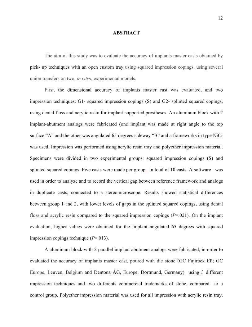
ABSTRACT
The aim of this study was to evaluate the accuracy of implants master casts obtained by
pick- up techniques with an open custom tray using squared impression copings, using several
union transfers on two, in vitro, experimental models.
First, the dimensional accuracy of implants master cast was evaluated, and two
impression techniques: G1- squared impression copings (S) and G2- splinted squared copings,
using dental floss and acrylic resin for implant-supported prostheses. An aluminum block with 2
implant-abutment analogs were fabricated (one implant was made at right angle to the top
surface “A” and the other was angulated 65 degrees sideway “B” and a frameworks in type NiCr
was used. Impression was performed using acrylic resin tray and polyether impression material.
Specimens were divided in two experimental groups: squared impression copings (S) and
splinted squared copings. Five casts were made per group, in total of 10 casts. A software was
used in order to analyze and to record the vertical gap between reference framework and analogs
in duplicate casts, connected to a stereomicroscope. Results showed statistical differences
between group 1 and 2, with lower levels of gaps in the splinted squared copings, using dental
floss and acrylic resin compared to the squared impression copings (P=.021). On the implant
evaluation, higher values were obtained for the implant angulated 65 degrees with squared
impression copings technique (P=.013).
A aluminum block with 2 parallel implant-abutment analogs were fabricated, in order to
evaluated the accuracy of implants master cast, poured with die stone (GC Fujirock EP; GC
Europe, Leuven, Belgium and Dentona AG, Europe, Dortmund, Germany) using 3 different
impression techniques and two differents commercial trademarks of stone, compared to a
control group. Polyether impression material was used for all impression with acrylic resin tray.

13
Seven groups were formed: G1 – control group; G2a – Squared impression copings, poured with
a die stone GC Fujirock EP; G2b – Squared impression copings, poured with a die stone Zero
Stone G3a – Splinted squared copings using dental floss and acrylic resin poured with a die
stone GC Fujirock EP; G3b- Splinted squared copings using dental floss and acrylic resin -
poured with a die stone Zero Stone; G4a - Splinted squared copings using dental floss and
bisacrilica resin - poured with a die stone GC Fujirock EP; G4b - Splinted squared copings using
dental floss and bisacrilica resin poured with a die stone Zero Stone. The distances between the
analogs of each specimen were measured, using a software, connected to the stereomicroscope.
Results presented statistical differences between the distances of G1 and G2a (p=0.010), G2b
(p=0.015), G4b (p=0.007). No statistical differences were found between G1 and G3a (p=0.178),
G3b (p=0.288), G4a (p=0.531). Splinted squared copings poured with a die stone GC Fujirock
EP produced cast most similar to the control Group.
In conclusion, the accuracy of the SS impression technique was superior to squared
impression copings (S), for implants presenting different angulation; the inaccuracy seen with
the squared impression copings (S) method seemed to correlate with the nonparallel (< 65°)
abutment relationship and the apparent deformation of the impression material.
14
DESCRIPTORS2
Dental Implants, Calcium Sulfate, Dental Impression Materials, Dental Impression Technique,
Dental Models
______________________
2MsSH – Medical Subject Headings, available at: www.nlm.nih.gov/mesh
15
Lista de Abreviaturas e siglas
RA: resina acrílica
µm: micrometro
mm: milímetro
Ncm: Newton centímetro

16
LISTA DE ANEXOS
Anexo A: Aprovação pela Comissão Científica e de Ética da Faculdade de
Odontologia/PUCRS................................................................................................................72
Anexo B: Normas do Periódico Journal of Prosthetic Dentistry .................................. .........73

17
SUMÁRIO

18
SUMÁRIO
INTRODUÇÃO GERAL ............................................................................................. 19
OBJETIVOS ................................................................................................................. 24
Objetivo Geral ............................................................................................................ 24
Objetivo Específico .................................................................................................... 24
ARTIGO DE PESQUISA 1 ......................................................................................... 25
Abstract ...................................................................................................................... 28
Introduction ................................................................................................................ 30
Material e Methods .................................................................................................... 31
Results. ....................................................................................................................... 34
Discussion .................................................................................................................. 35
References .................................................................................................................. 39
ARTIGO DE PESQUISA 2 ......................................................................................... 45
Abstract ..................................................................................................................... 46
Introduction ................................................................................................................ 49
Material e Methods .................................................................................................... 50
Results ........................................................................................................................ 53
Discussion .................................................................................................................. 54
References .................................................................................................................. 57
DISCUSSÃO GERAL .................................................................................................. 64
CONCLUSÕES ............................................................................................................. 71
REFERÊNCIAS BIBLIOGRÁFICAS ....................................................................... 72
ANEXOS ........................................................................................................................ 74

19
INTRODUÇÃO GERAL

20
INTRODUÇÃO GERAL
O crescente interesse dos pacientes pela reposição de seus dentes perdidos e a continua
evolução dos implantes osseointegrados, proporcionam uma valorização da odontologia
restauradora. O sucesso das restaurações protéticas com implantes dentários está diretamente
ligado a adaptação passiva entre prótese e implante e uma adequada distribuição das forças
mastigatórias (1). O problema da passividade entre infraestruturas metálicas e barras sobre
implantes merecem atenção, uma vez que a conexão forçada da estrutura metálica da prótese
implanto retida pode resultar em problemas biológicos como micro-fraturas do tecido ósseo e
zonas de isquemia marginal ou problemas mecânicos que incluem o afrouxamento dos parafusos
ou a fratura dos componentes protéticos (2). Isto é importante para o sucesso a longo prazo da
sobrevida dos implantes e da preservação do tecido ósseo (3). Existem diferentes variáveis
clínicas e laboratoriais que podem afetar a acurácia dos modelos de implantes como as diferentes
técnicas de moldagem, diferentes materiais, propriedades e técnicas para vazamento dos gessos,
tolerância das máquinas dos componentes protéticos, angulação e profundidade dos implantes,
tipos de fundição (4) (5). Várias técnicas de moldagem foram desenvolvidas como tentativa de
obter um modelo de trabalho que resultará maior precisão clinica para o assentamento das
próteses múltiplas implanto retidas.
A técnica do casquete cônico também denominada de moldagem de transferência utiliza
moldeiras fechadas, transferentes cônicos que possibilitam a sua permanência na cavidade bucal
após a remoção do molde. Esta técnica apresenta uma menor precisão devido a ausência de
paralelismo dos pilares, deformação do material de moldagem e a presença de ar entre o molde e
o transferente impedem o perfeito assentamento do transferente (1).
A técnica de sacar ou moldagem de arrasto utiliza moldeira aberta e transferes quadrados.
21
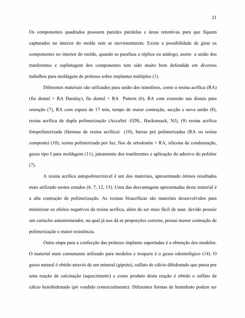
Os componentes quadrados possuem paredes paralelas e áreas retentivas para que fiquem
capturados no interior do molde sem se movimentarem. Existe a possibilidade de girar os
componentes no interior do molde, quando se parafusa a réplica ou análogo, assim a união dos
tranferentes e esplintagem dos componentes tem sido muito bem defendida em diversos
trabalhos para moldagem de próteses sobre implantes múltiplos (1).
Diferentes materiais são utilizados para união dos transferes, como a resina acrílica (RA)
(fio dental + RA Duralay), fio dental + RA Pattern (6), RA com extensão nas distais para
retenção (7), RA com espera de 17 min, tempo de maior contração, secção e nova união (8),
resina acrílica de dupla polimerização (AccuSet -EDS,. Hackensack, NJ), (9) resina acrílica
fotopolimerizada (lâminas de resina acrílica) (10), barras pré polimerizadas (RA ou resina
composta) (10), resina polimerizada por luz, fios de ortodontia + RA, silicona de condensação,
gesso tipo I para moldagem (11), jateamento dos tranferentes e aplicação do adesivo do poliéter
(7).
A resina acrílica autopolimerizavel é um dos materiais, apresentando ótimos resultados
mais utilizado nestes estudos (6, 7, 12, 13). Uma das desvantagens apresentadas deste material é
a alta contração de polimerização. As resinas bisacrílicas são materiais desenvolvidos para
minimizar os efeitos negativos da resina acrílica, além de ser mais fácil de usar, devido possuir
um cartucho automisturador, na qual já nos dá as proporções corretas, possui menor contração de
polimerização e maior resistência.
Outra etapa para a confecção das próteses implanto suportadas é a obtenção dos modelos.
O material mais comumente utilizado para modelos e troqueis é o gesso odontológico (14). O
gesso natural é obtido através de um mineral (gipsita), sulfato de cálcio dihidratado que passa por
uma reação de calcinação (aquecimento) e como produto desta reação é obtido o sulfato de
cálcio hemihidratado (pó vendido comercialmente). Diferentes formas de hemidrato podem ser
22
obtidas: α- hemidrato, α- hemidrato modificado e o β- hemidrato (14). O α- hemidrato
modificado é fabricado quando pela fervura da gipsita em uma solução aquosa de cloreto de
cálcio e cloreto de magnésio a 30%. Este processo permite que os pós produzidos sejam
partículas mais lisas e densas entre os três tipos. Este é denominado de gesso natural. É possível
produzir sinteticamente os α- hemidratos e β- hemidratos a partir dos subprodutos ou produtos
residuais da produção do ácido fosfórico. Gesso artificial. O produto sintético é geralmente
muito mais dispendioso do que a produção a partir da gipsita natural, mas quando o produto é
produzido de forma adequada suas propriedades são iguais ou excedem aquelas dos gessos
naturais. Podermos classificar os gessos quanto a sua expansão: sem expansão (zero de
expansão) e gessos com expansão (superior a 0,01%). O Gesso Fujirock segundo o fabricante
possui 0,08% de expansão, o Zero Stone possui segundo o fabricante 0,0% de expansão.
O gesso dever ter as seguintes propriedades: compatibilidade com os materiais de
moldagem, precisão dimensional, reprodução de detalhes, adequado tempo de trabalho, mínima
expansão, alta resistência a compressão, resistência a fratura e abrasão , dureza de superfície,
facilidade de manipulação, ausência de toxicidade, e resistência transversal (15).
Os principais requisitos para os materiais dos modelos odontológicos são dureza
superficial e mínima expansão. Várias tentativas dos fabricantes tem sido feitas pra melhorar
estes requisitos, como controle da temperatura da calcinação, tempo de queima, procedimento de
pulverização para a obtenção do pó (14).
Materiais a base de resina acrílica estão disponíveis para a fabricação de modelos
odontológicos, entretanto a alta contração de polimerização destes materiais afeta a precisão dos
modelos. Alguns fabricantes desenvolveram gessos modificados por resinas na tentativa de
melhorar a dureza superficial, entretanto alguns estudos mostram problemas com a estabilidade

23
dimensional (15-17). O Gesso tipo IV é o material mais utilizado para a confecção de modelos
de trabalho.
Na busca de um trabalho com exatidão, busca-se observar todas as variáveis envolvidas
nas etapas de confecção, sem desprezar nenhum ponto que possa servir de elo fraco da cadeia.
Sendo assim além da utilização de materiais e técnicas de moldagem adequadas para moldagem
de implantes múltiplos devemos observar os materiais para obtenção dos modelos de trabalho
pra que o objetivo almejado de uma infra estrutura com assentamento passivo seja obtida.
Quatro hipóteses nulas foram testadas:
1) Não existem diferenças na precisão dos modelos de gesso quando utilizada a técnica
de moldagem de arrasto, sem união dos componentes e unidos com resina acrílica em
implantes perpendicular a superfície e inclinados a 65°.
2) Não existe diferenças na precisão dos modelos de gesso quando utilizada a técnica de
moldagem de arrasto em implantes perpendicular a superfície e inclinados a 65°.
3) Não existe diferenças na precisão dos modelos de gesso quando utilizada a técnica de
moldagem de arrasto, quando utilizada ausência de união dos transferentes e
diferentes materiais de união dos componentes, união com resina acrílica e união
com resina bisacrílica nanoparticulada em implantes paralelos.
4) Não existem diferenças significantes na precisão dos modelos de gesso utilizando
diferentes marcas de gesso (Fuijirock e Zero Stone) para obtenção dos modelos em
próteses com implantes paralelos.

24
OBJETIVOS
Objetivo geral
Avaliar a precisão dos modelos de gesso obtidos pela técnica de moldagem de sacar ou de
arrasto, com a utilização de moldeira aberta e utilizando diferentes materiais de união dos
componentes quadrados.
Objetivos específicos
Avaliar a precisão dos modelos de gesso utilizado a:
1) Técnica de moldagem de arrasto sem união dos componentes e unidos com resina acrílica em
implantes perpendicular a superfície e inclinados a 65°.
2) Técnica de moldagem de arrasto em implantes perpendicular a superfície e inclinados a 65°.
3) Técnica de moldagem de arrasto, quando utilizada ausência de união dos transferentes e
diferentes materiais de união dos componentes, união com resina acrílica e união com resina
bisacrílica nanoparticulada em implantes paralelos.
4) Técnica de arrasto vazados com diferentes marcas de gesso tipo IV quando comparados a um
grupo controle em implantes paralelos.

25
CAPÍTULO I
26
CAPÍTULO I
ARTIGO 1
Title: Angulation effect and impression techniques or the accuracy of master cast using metal framework
Artigo nas normas do Periódico The Journal of Prosthetic Dentistry Qualis A2 e Fator de
Impacto 1,724 (Anexo B).

27
Title: Angulation effect and impression techniques or the accuracy of master cast using metal framework
Author names and affiliations:
Anne Buss Becker1, Hugo Mitsuo Silva Oshima2
1Graduate Program of Dental School, PUCRS, 2School of Dentistry, PUCRS;
Corresponding Author: Hugo Mitsuo Silva Oshima, School of Dentistry, Pontifícia
Universidade Católica do Rio Grande do Sul, Avenida Ipiranga, 6681, Partenon, 90619-900,
Porto Alegre, Brazil. Phone number: 55 51 3320 3562; Fax number: 55 51 3320 3626; E-mail:

28
Abstract:
Statement of problem. Accurate recording of implant location is required in every implant-
supported prostheses. Implant angulation, which is inevitable in several clinical situations, could
affect the impression accuracy.
Purpose. This in vitro study aimed to compare the accuracy of implants master cast, and two
impression techniques: squared impression copings and splinted squared copings, using dental
floss and acrylic resin (Pattern Resin) for implant-supported prostheses placed with different
angles, and the effect of the angulation of the 90° and 65°.
Material and methods. An aluminum block with 2 implant-abutment analogs were fabricated
(one implant was made at right angle to the top surface and the other was angulated 65 degrees
sideway). Frameworks in type NiCr alloy. Polyether impression material was used for all
impression with acrylic resin tray. Two experimental groups were formed: squared impression
copings and splinted squared copings using dental floss and acrylic resin - Pattern Resin. Five
casts were made per group, in total of 10 casts. The software AxionVision 4.8.1, was used in
order to analyze and to record the vertical gap between reference framework and analogs in
duplicate casts that received the images from a camera coupled to a stereomicroscope, observed
at 10X magnification. The gap values were analysed using analysis of variance (ANOVA). The
level of significance was set at 5%.
Results. The squared impression copings showed significantly different vertical gaps according
to the angulation of implant (P < .05) in comparison to splinted squared copings using dental
floss and acrylic resin - Pattern Resin. Each implant when compared separately, there was a
vertical gaps greater for implant angle at 65 degrees with squared impression copings technique
(S) (P < .05).

29
Conclusions. Under the limitations of this study, the accuracy of the splinted squared impression
technique was superior to squared impression copings, for implants presenting different
angulation.
CLINICAL IMPLICATIONS
For the situation in which two or more implants are placed, the transfer impression thechnique is
indicated. The use of the splinted technique is recommended for implant impression.

30
INTRODUCTION
Dental implants, which do not present a periodontal ligament, are not able to compensate
not even minor misfits of the superstructure.1 Therefore, recording a correct 3-dimensional
orientation rather than surface detail is necessary to avoid biologic and technical complications. 2
It is appropriate to ensure accurate reproduction of the implant relationship in the working cast
for the fabrication of a passively fitting framework. The accuracy of the master cast depends on
the type of impression material, the implant impression technique and the accuracy of the die.3
Whereas the influence of different impression materials appears to be less critical, impression
techniques are considered as a major factor that could influence impression accuracy.3,4
Several implant impression techniques, such as splint, pick- up and transfer techniques,
have been introduced and investigated regarding to their accuracy. Other factors related to the
accuracy of the implant impression, including the angulation and implants depht, have also been
studied. The chosen of an indirect technique, which uses tapered transfer copings and a closed
stock tray, is controversial because while it requires less difficult clinical procedures it probably
involves greater instability. 5,6 Likewise, the advantages of splinting and of each splinting
technique used in the direct technique, have not been established at the moment. 7 One advantage
of the direct technique, which uses square transfer copings with an open custom tray, would be
greater transfer precision because of the splinting stability during the impression removal and
analog connection. 8,9
When multiple implants are placed with different angles, the distortion of the impression
material on removal may increase. Two studies reported less accurate impressions using
angulated implants instead of straight implants using an experimental cast with 4 or 5 implants.
6,10 On the other hand, 2 other studies that used 2 or 3 implants reported effect of the angulation
on the accuracy of impressions.12 Also, this effect may be increased by higher number of

31
implants.
Two null hypotheses were tested. Fisrt, there are no differences in accuracy of implants
master cast when used two impresson technique: square impression copings and splinted square
coping using dental flos and acrylic resin: Patter resin for implant implant-supported prostheses
placed with different angles. Second, there are no differences in accuracy of implants master cast
when used to implant positioned at 90° in relation to the surface of the matrix and 65°.
The purpose of this in vitro study was to investigate the angulation effect and impression
techniques (squared impression copings, squared impression copings splinted using dental floss
and acrylic resin) on the accuracy of master cast using metal framework, compared to the control
group.
MATERIAL AND METHODS
Fabrication of the Master Cast
An aluminum block has 20 mm (width) x 20 mm (height) x 30 mm (length), presenting
two holes 20 mm apart from each other was used to serve as a clinically relevant simulation.
Two minipilar 4.1 titanium analogs (Neodent SA Curitiba, Parana, Brazil) were placed at 65°
sideways and 90° in relation to the surface of the aluminum block and secured by screws (Fig 1).
The stopper block presents a lateral and circling the two mm receded, which acts as stop device
for trays.
Fabrication of de framework
A master framework (Fig 2) was made using waxed with two CoCr UCLA for
overcasting (Neodent SA Curitiba, Parana, Brazil). NiCr alloy was used (Fit Cast V, Talmax,
Curitiba, Paraná, Brazil)as the standard for the assessment of all subsequent measurements,
which was made to determinate the accuracy of casts made using different transfer procedures.

32
Fabrication and prepare of Custom Trays
Two custom autopolymerizing acrylic resin trays (Jet- Clássico, Campo Limpo, SP,
Brazil) were fabricated using the aluminum block in this study. One of them was used for the
squared impression copings technique and the other one was used for the splinted squared
copings using dental floss and acrylic resin. These trays had a 3 mm relief for impression
material, with 2 spaces to allow access to the coping screws.
Tray polyether adhesive (3M ESPE, Seefeld, Germany) was applied thinly and evenly
over the inner surface of each tray, extended approximately 3 mm onto the outer surface of the
tray, along the periphery. The adhesive was allowed to dry for 15 minutes before the impressions
were made.
Transfer Procedures
Two groups with 5 casts each were formed.
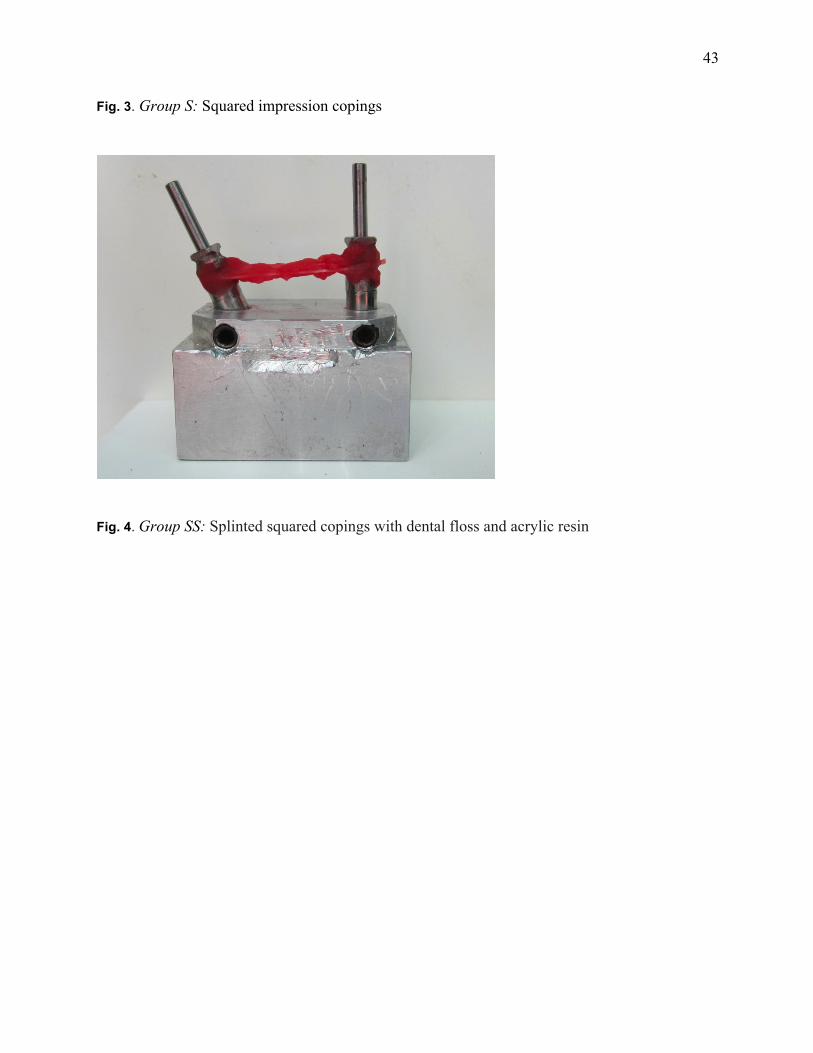
Group S - Squared impression copings. (Figure 3)
Group SS - Splinted squared copings using dental floss and acrylic resin - Pattern Resin (GC
Europe, Leuven, Belgium). (Figure 4)
Soft viscosity polyether (Impregum Penta Soft; 3M ESPE, Seefeld, Germany) was the
impression material chosen for all transfer procedures.13,14 Automatic mixing and dispenser
Pentamix 2 (3M ESPE, Seefeld, Germany) was used to standardize all mixtures. Polyether was
injected around the transfer copings and placed inside the custom tray using the dispenser. The
tray was seated on the aluminum block with gentle pressure until the lateral and circling stops
contacted the base of the aluminum block. The impression material was allowed to set for 12
minutes from the start of mixing; the manufacturer’s setting time was doubled to compensate a
delayed polymerization reaction at room temperature rather than at mouth temperature. A
standardized load of 1.25 kg was exerted over each tray during the impression procedures. 14, 15

33
This was enough to force the excess material to flow out and to maintain constant pressure
throughout the working time.
Transfer Copings
Group S: Squared impression copings (Fig. 3). The squared impression copings were adapted to
the abutment analogs on the aluminum block using 10 Ncm of torque.
Group SS: Splinted squared copings with dental floss and acrylic resin – Pattern (GC Europe,
Leuven, Belgium) (Fig. 4). The squared impression copings were adapted to the abutment
analogs on the aluminum block using 10 Ncm of torque. Dental floss was adaptaded to squared
impression copings, and the autopolymerizing acrylic resin (Pattern GC Europe, Leuven,
Belgium) wraped around the copings and dental floss.
Specimen Preparation
After the impression material polymerization impression copings were unscrewed and the
tray was separated from the aluminum block. The minipilar abutment analogs (Neodent SA
Curitiba, Parana , Brazil) were fit to the impression copings using 10 Ncm of torque while the
copings were held with a hemostatic forceps to prevent the squared coping from rotating inside
the impression. 16 This procedure was not necessary for the modified squared technique, but it
was performed in order to standardize the methodology.
The impressions were poured with a die stone Zero Stone (Dentona AG, Dortmund,
Germany), 30 minutes after the impressions were made. A ratio of 23 ml of distilled water to 100
g of stone was used, and the stone was manually mixed for 15 seconds to incorporate the water.
Then mechanically mixed under vacuum for 45 seconds with a digital vacuum spatulator
(Turbomix EDG Equipment, São Carlos, SP, Brazil). All mixes were vibrated into the
impression. The stone casts were allowed to set for 2 hours before separation from the
impressions.

34
All casts obtained were stored at room temperature for a minimum of 2 weeks before
measurement. 16
Measurement of accuracy
The standard framework was seated on each cast and a titanium screw was tightened in
analog right and left to a 10 Ncm using torque driver (Neodent SA Curitiba, Parana, Brazil) for
measurements of implant analog-framework interface gaps. The examiner was calibrated and
blinded to all definitive casts measurements
After 7 days, these measurement were analyzed using software (AxionVision 4.8.1,
Zeiss; Carl Zeiss, Jena, Germany) that received the images from a camera (AxionCam ICc3,
Zeiss; Carl Zeiss, Jena, Germany) coupled to a stereomicroscope (Zeiss Discovery V20; Carl
Zeiss, Jena, Germany), observed at 10X magnification.
Vertical gaps of the analogs were assessed in anterior directions for each cast.
Demarcations were made in the center of each analog to standardize the vertical gaps values. For
each image, 4 vertical gaps values at the same point were reading between implant analog-
framework interface 90° and 65° .
Statistical analysis
Gap values were analyzed using the SPSS/PC Statics 22 software (SPSS Inc., Chicago,
IL, USA), using analaysis of variance (ANOVA). The level of significance was set at 5%.
RESULTS Sample included 10 specimens (n=5) and one master cast (Aluminum block and
framework as a control group. Table 1 shows the mean, standard deviations of
abutment/framework interface gaps of master cast, implant 90°, implant 65°, and combined
implants 90° and 65°.

35
Table 2 shows the mean, standard deviations of abutment/framework interface gaps
between groups S and SS combined sideways. Significant differences were detected between
Group S - squared copings and Group SS -Splinted squared copings techniques (P = .021).
Table 3 shows the mean, standard deviations, of abutment/framework interface gaps for
each side 90° and 65°. Significant differences were found between side 65° (Group S) - squared
copings and others (P =.013).
DISCUSSION
The master cast reproduces the intraoral position of the implants surrounding by osseous
tissue and soft tissues as accurately as possible, to allow the fabrication of passively fitting
prostheses and, consequently, eliminating the strain on the supporting components around the
bone. 17
A passive fit occurs when all the surfaces of the implant and prosthesis are aligned with
no force application and when the gap formed between the metallic framework and implants are
within the limits established by science (111 µm or 0.11 mm). 18 A perfect fit occurs when all
the matching surfaces of the implant and prosthesis are in alignment and in contact with no force
application. 19 In order to identify a passive fit, the master cast used in this study was fabricated
using a previously completed metal framework.
Several factors surround the the implant transfering position from mouth to cast,
including the implant connection type and impression coping design, the number of implants and
angulation, the impression technique and the impression material. Whereas the influence of
different impression materials appears to be less critical, impression techniques are considered as
a major factor that could influence impression accuracy. 3,4,20
The scientific literature provides two impression techniques: pick-up and transfer

36
techniques. The transfer techniques implant impression copings can be repositioned into the
impression material after impression making with a tapered impression copings associated to
closed tray (indirect, transfer) technique. On the other hand, in the pick-up technique, the square
impression copings are unscrewed of the implant after the setting of the impression material and
removed from the mold, using an opened tray. Both techniques and their modifications are used
to achieve implant impression accuracy.
The null hypothesis of the present study, stating that the accuracy of casts would not be
affect by the impression technique, was rejected. Significant differences were detected between
the square copings and splinted squared copings techniques (P = .021), when the implant
angulation was used. When multiple implants are placed with different angles, the distortion of
the impression material on removal seemed to increase.
These findings are in accordance to Carr et al. 6 who detected difference between direct
transfer method and indirect transfer method. The inaccuracy found using indirect transfer
method seemed to correlate with the nonparallel (< l 5°) abutment relationship and the apparent
deformation of the impression material.
Akalin et al. 2013 21 compared the effects of implant angulation (10° buccal angulation),
impression material (condensation silicone, polyvinyl siloxane, and polyether), and variation in
width of the arch curvature on transfer models. The results showed that angular model
measurements presented the greatest deformation values (P < .05). All impression materials
showed deformation and the polyether impression models showed statistically significantly less
deformation in angular measurements (P < .05).
In the study of Assunção et al. 2010 23 the authors compared 2 splinted impression
transfer techniques (splinted with self-curing acrylic resin and with condensation silicone) The
implants were positioned at 90, 80, 75, and 65 degrees in relation to the surface of the matrix.
37
Significant differences were found among groups. These results suggest that condensation
silicone may not be used as an alternative for splinting material. Furthermore, implant inclination
may affect master cast accuracy (75 degrees).
The results of the present study are in desagrement with the studies of the Lee et al 2010
24(18), Conrad et al 200712, Choi et al 200711 Ehsani et al 2013 22 and Reddy et al 201325 ,in
which no differences between the angulation of implants were found.
Lee et al 2010 24 compared the accuracy of an abutment-framework (A-F) taken with
open tray impression technique, combining cement on crown abutments, a metal framework and
resin cement to closed tray and resin-splinted open tray impression techniques for the 3-implant
definitive casts (angulations 0, 30, and 40 degrees). The authors concluded that the accuracy of
the A-F impression technique was superior to that of conventional techniques, and was not
affected by the angulation of the implants.
The purpose of the study of Conrad et al 200712 was to determinate the effect of
combined interaction of impression technique, implant angulation, and implant number on the
accuracy of implant definitive casts. The magnitude of distortion was similar for all
combinations of impression technique, implant angulation, and implant number.
Choi et al 2007 11 evaluated the accuracy of 2 implant-level impression techniques (direct
nonsplinted and splinted) for the fabrication of multi-unit internal-connection implant
restorations in 2 simulated clinical settings (parallel and divergent) using a laboratory model. The
accuracy of implant-level impressions for internal-connection implant restorations was similar,
for the direct nonsplinted and splinted techniques in settings with divergence up to 8 degrees.
Ehsani et al 201322 evaluated the accuracy of impressions made of parallel and
nonparallel implants (30 degrees) with different lengths (2, 1.5, or 1mm) of impression coping
connections. There was no significant difference in impression accuracy, regardless of the
38
lengths of the impression connections. Additionally, there was no significant difference between
the impression accuracy of inclined and straight implants, except in the y-axis (P =.006). Reddy
at al 201325 evalueted the accuracy of difference impression materiais (polyvinyl siloxane and
polyether) in parallel and angulated (10 and 15 degrees) implants. No significant diferences were
found in dimensional accuracy for the resultant cast made from two diferente impression
materials in parallel and angulated implants.
The contradictory results for transfer accuracy that have been reported in the literature
may be partially explained by the use of different methodologies to assess the accuracy. Some
experiments used microscopy to measure the displacement of analogs in the specimens in
comparison to definitive cast at selected points. 23
Therefore, more studies are necessary to improve impression and laboratory procedures.
To determine the amount of discrepancy physiologically and mechanically tolerated and to
clinically analyze failures and their complications in implant treatment.
CONCLUSIONS
Under the limitations of this study, the splinted squared copings using dental floss and
acrylic resin produced an accurated cast in comparison to the squared technique when use
implant angulation. The inaccuracy seen with the squared impression copings (S) method
seemed to correlate with the nonparallel (< 65°) abutment relationship and the apparent
deformation of the impression material.

39
REFERENCES
1. Cordaro L, Ercoli C, Rossini C, Torsello F, Feng C. Retrospective evaluation of complete-arch fixed partial dentures connecting teeth and implant abutments in patients with normal and reduced periodontal support. J Prosthet Dent. 2005 Oct;94(4):313-20. 2. Vigolo P, Fonzi F, Majzoub Z, Cordioli G. An evaluation of impression techniques for multiple internal connection implant prostheses. J Prosthet Dent. 2004 Nov;92(5):470-6. 3. Lee H, So JS, Hochstedler JL, Ercoli C. The accuracy of implant impressions: a systematic review. J Prosthet Dent. 2008 Oct;100(4):285-91. 4. Wostmann B, Rehmann P, Balkenhol M. Influence of impression technique and material on the accuracy of multiple implant impressions. Int J Prosthodont. 2008 Jul-Aug;21(4):299-301. 5. Humphries RM, Yaman P, Bloem TJ. The accuracy of implant master casts constructed from transfer impressions. Int J Oral Maxillofac Implants. 1990 Winter;5(4):331-6. 6. Carr AB. Comparison of impression techniques for a five-implant mandibular model. Int J Oral Maxillofac Implants. 1991 Winter;6(4):448-55. 7. Herbst D, Nel JC, Driessen CH, Becker PJ. Evaluation of impression accuracy for osseointegrated implant supported superstructures. J Prosthet Dent. 2000 May;83(5):555-61. 8. Assif D, Marshak B, Schmidt A. Accuracy of implant impression techniques. Int J Oral Maxillofac Implants. 1996 Mar-Apr;11(2):216-22. 9. Nissan J, Gross M, Shifman A, Assif D. Stress levels for well-fitting implant superstructures as a function of tightening force levels, tightening sequence, and different operators. J Prosthet Dent. 2001 Jul;86(1):20-3. 10. Assuncao WG, Filho HG, Zaniquelli O. Evaluation of transfer impressions for osseointegrated implants at various angulations. Implant Dent. 2004 Dec;13(4):358-66. 11. Choi JH, Lim YJ, Yim SH, Kim CW. Evaluation of the accuracy of implant-level impression techniques for internal-connection implant prostheses in parallel and divergent models. Int J Oral Maxillofac Implants. 2007 Sep-Oct;22(5):761-8. 12. Conrad HJ, Pesun IJ, DeLong R, Hodges JS. Accuracy of two impression techniques with angulated implants. J Prosthet Dent. 2007 Jun;97(6):349-56. 13. Lorenzoni M, Pertl C, Penkner K, Polansky R, Sedaj B, Wegscheider WA. Comparison of the transfer precision of three different impression materials in combination with transfer caps for the Frialit-2 system. J Oral Rehabil. 2000 Jul;27(7):629-38. 14. Naconecy MM, Teixeira ER, Shinkai RS, Frasca LC, Cervieri A. Evaluation of the accuracy of 3 transfer techniques for implant-supported prostheses with multiple abutments. Int J Oral Maxillofac Implants. 2004 Mar-Apr;19(2):192-8. 15. Del'Acqua MA, Arioli-Filho JN, Compagnoni MA, Mollo Fde A, Jr. Accuracy of impression and pouring techniques for an implant-supported prosthesis. Int J Oral Maxillofac Implants. 2008 Mar-Apr;23(2):226-36. 16. Del'Acqua MA, Chavez AM, Compagnoni MA, Molo Fde A, Jr. Accuracy of impression techniques for an implant-supported prosthesis. Int J Oral Maxillofac Implants. 2010 Jul-Aug;25(4):715-21. 17. Avila ED, Moraes FD, Castanharo SM, Del Acqua MA, Mollo Junior FA. Effect of Splinting in Accuracy of Two Implant Impression Techniques. J Oral Implantol. 2012 Oct 26. 18. Jemt T, Book K. Prosthesis misfit and marginal bone loss in edentulous implant patients. Int J Oral Maxillofac Implants. 1996 Sep-Oct;11(5):620-5.

40
19. Chee W, Jivraj S. Impression techniques for implant dentistry. Br Dent J. 2006 Oct 7;201(7):429-32. 20. Al-Abdullah K, Zandparsa R, Finkelman M, Hirayama H. An in vitro comparison of the accuracy of implant impressions with coded healing abutments and different implant angulations. J Prosthet Dent. 2013 Aug;110(2):90-100. 21. Akalin ZF, Ozkan YK, Ekerim A. Effects of implant angulation, impression material, and variation in arch curvature width on implant transfer model accuracy. Int J Oral Maxillofac Implants. 2013 Jan-Feb;28(1):149-57. 22. Ehsani S, Siadat H, Alikhasi M. The effect of implant connection length on the dimensional impression accuracy of inclined implants. Int J Oral Maxillofac Implants. 2013 Nov-Dec;28(6):e315-20. 23. Assuncao WG, Britto RC, Ricardo Barao VA, Delben JA, dos Santos PH. Evaluation of impression accuracy for implant at various angulations. Implant Dent. 2010 Apr;19(2):167-74. 24. Lee HJ, Lim YJ, Kim CW, Choi JH, Kim MJ. Accuracy of a proposed implant impression technique using abutments and metal framework. J Adv Prosthodont. 2010 Mar;2(1):25-31. 25. Reddy S, Prasad K, Vakil H, Jain A, Chowdhary R. Accuracy of impressions with different impression materials in angulated implants. Niger J Clin Pract. 2013 Jul-Sep;16(3):279-84.

41
Fig.1. Aluminum block
Fig. 2. Framework

42
43
Fig. 3. Group S: Squared impression copings
Fig. 4. Group SS: Splinted squared copings with dental floss and acrylic resin

44
Table I. The mean, standard deviations (µm) of abutment/framework interface gaps of master
cast
Master Cast Mean (µm) Standard deviation (µm)
Implant 65° 60 9
Implant 90° 30 14
Combined implants 65° and 90° 40 10
Table II. The mean, standard deviations (µm) of abutment/framework interface gaps between
groups S and SS combined implants A and B
Group Mean (µm) Standard deviation (µm)
S 280 460
SS 80 * 70
* (P=.021)
Table III. The mean values, standard deviations, of abutment/framework interface gaps for each side “A”and “B”. Side Group Mean (µm) Standard deviation (µm) 90° S
SS
50
50
210
170
65° S
SS
510*
110
570
90
* (P=.013)

45
CAPÍTULO II
46
CAPÍTULO II
The Journal of Prosthetic Dentistry
Title: Accuracy of implant master casts constructed by different impression techniques and
trademarks of stone
Author names and affiliations:
Anne Buss Becker1, Hugo Mitsuo Silva Oshima2
1Postgraduate Program of Dental College, PUCRS, 2Faculty of Dentistry, PUCRS;
Corresponding Author: Hugo Mitsuo Silva Oshima, School of Dentistry, Pontifícia
Universidade Católica do Rio Grande do Sul, Avenida Ipiranga, 6681, Partenon, 90619-900,
Porto Alegre, Brazil. Phone number: 55 51 3320 3562; Fax number: 55 51 3320 3626; E-mail:
47
Abstract
Statement of problem. In dental implant restorations, a lack of passivity may be associated with
mechanical failure. The accuracy of implants master cast depends on the type of impression
material, implant impression technique and die material.
Purpose. This in vitro study evaluated the accuracy of implants master cast, poured with die
stone (Fujirock and Zero Stone) using 3 different impression techniques (squared impression
copings; squared impression copings splinted using dental floss and acrylic resin; and squared
impression copings splinted using dental floss and bis-acrylic resin) compared to a control
group.
Material and methods. An aluminum block with 2 parallel implant-abutment analogs was
fabricated. Polyether impression material was used for all impression with acrylic resin tray.
Specimens were divided into seven groups (a control group – aluminum block with analogs and
6 groups combining type of stone and impression technique). Five casts were made per group,
totalizing 30 casts. The measurement between analogs was analyzed using a software
AxionVision 4.8.1 coupled to a stereomicroscope, observed at 10X magnification. Distances
between the implants were compared to the average of the distances the implants to aluminum
block.
Results. Results showed statistically significant differences between control Group (G1)-
aluminum block and groups 2a - Squared impression copings, poured with a die stone
(Fujirock); Group 2b - Squared impression copings, poured with a die stone (Zero Stone); and
Group 4b - Splinted squared copings with dental floss and bis-acrylic resin (Protemp 4), poured
with a die stone Zero Stone; (p=0.05).
Conclusions. Under the limitations of this study, the splinted squared copings using dental
48
floss and acrylic resin and splinted squared copings using dental floss and bis-acrylic resin
poured with a die stone Fujirock produced cast most similar to control Group.
CLINICAL IMPLICATIONS
For the situation in which 2 or more implant are placed, the transfer impression technique is
indicated. The use of the splinted technique is recommended for implant impression.
49
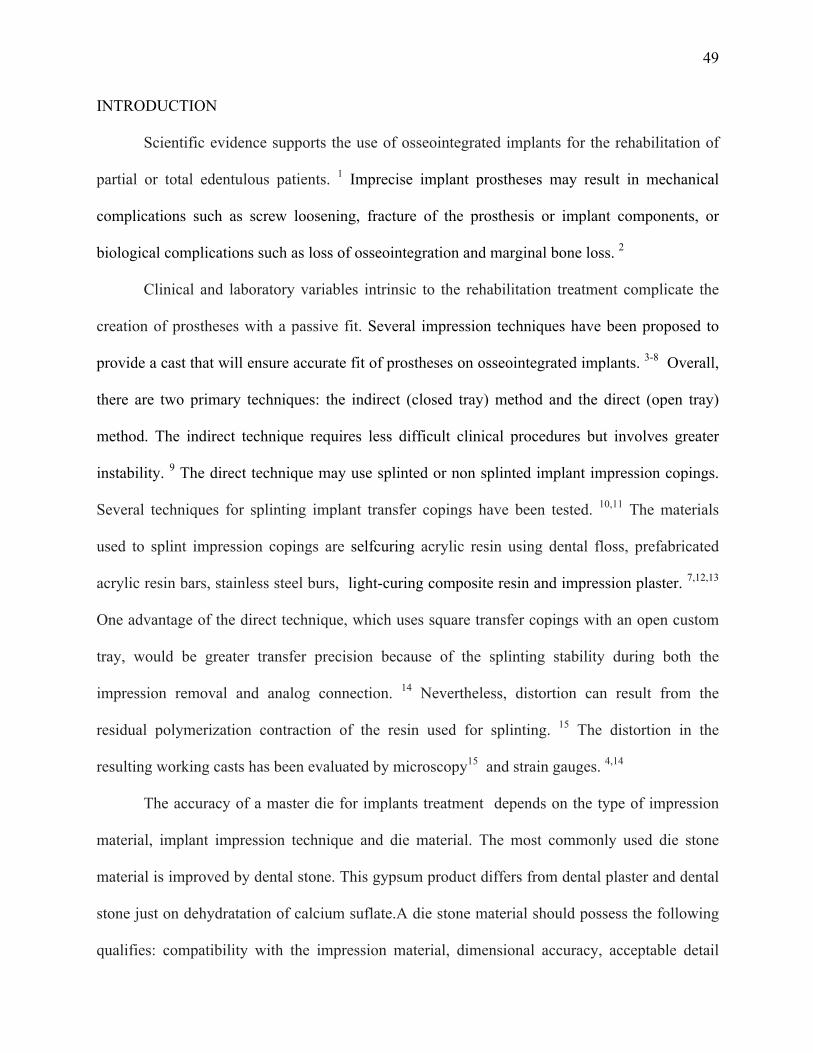
INTRODUCTION
Scientific evidence supports the use of osseointegrated implants for the rehabilitation of
partial or total edentulous patients. 1 Imprecise implant prostheses may result in mechanical
complications such as screw loosening, fracture of the prosthesis or implant components, or
biological complications such as loss of osseointegration and marginal bone loss. 2
Clinical and laboratory variables intrinsic to the rehabilitation treatment complicate the
creation of prostheses with a passive fit. Several impression techniques have been proposed to
provide a cast that will ensure accurate fit of prostheses on osseointegrated implants. 3-8 Overall,
there are two primary techniques: the indirect (closed tray) method and the direct (open tray)
method. The indirect technique requires less difficult clinical procedures but involves greater
instability. 9 The direct technique may use splinted or non splinted implant impression copings.
Several techniques for splinting implant transfer copings have been tested. 10,11 The materials
used to splint impression copings are selfcuring acrylic resin using dental floss, prefabricated
acrylic resin bars, stainless steel burs, light-curing composite resin and impression plaster. 7,12,13
One advantage of the direct technique, which uses square transfer copings with an open custom
tray, would be greater transfer precision because of the splinting stability during both the
impression removal and analog connection. 14 Nevertheless, distortion can result from the
residual polymerization contraction of the resin used for splinting. 15 The distortion in the
resulting working casts has been evaluated by microscopy15 and strain gauges. 4,14
The accuracy of a master die for implants treatment depends on the type of impression
material, implant impression technique and die material. The most commonly used die stone
material is improved by dental stone. This gypsum product differs from dental plaster and dental
stone just on dehydratation of calcium suflate.A die stone material should possess the following
qualifies: compatibility with the impression material, dimensional accuracy, acceptable detail
50
reproduction, fineness, adequate setting time, minimal setting expansion, high compressive
strength, fracture and abrasion resistance, surface hardness, ease and efficiency of manipulation,
lack of toxicity, and transverse strength.16 Most high-strength die stone materials (Types IV and
V) are used with a high degree of success as die materials for master casts fabrication.
Two null hypotheses were tested. Fisrt, there are no differences in accuracy of implants
master cast when used three impression technique: square impression copings, splinted square
coping using dental floss and acrylic resin (Patter resin) and splinted square coping using dental
floss and bis-acrylic resin (Protemp) for paralel implant. Second, there are no differences in
accuracy of implants master cast when used different trademarks of stone for paralel implant.
This in vitro study aimed to assess the accuracy of implants master die, poured with die
stone (Fujirock; and Zero Stone) and 3 impression techniques (squared impression copings,
squared impression copings splinted using dental floss and acrylic resin and squared impression
copings splinted using dental floss and bisacrilica resin) compared to control group.
MATERIAL AND METHODS
Fabrication of the Master Cast
A aluminum block presenting 20 mm (width) x 20 mm (height) x 30 mm (length), two
holes 20 mm apart from each other, containing two multiunit 4.1 titanium analogs (Neodent SA
Curitiba, Parana, Brazil) inserted into parallel to each other, secured by screws. The stopper
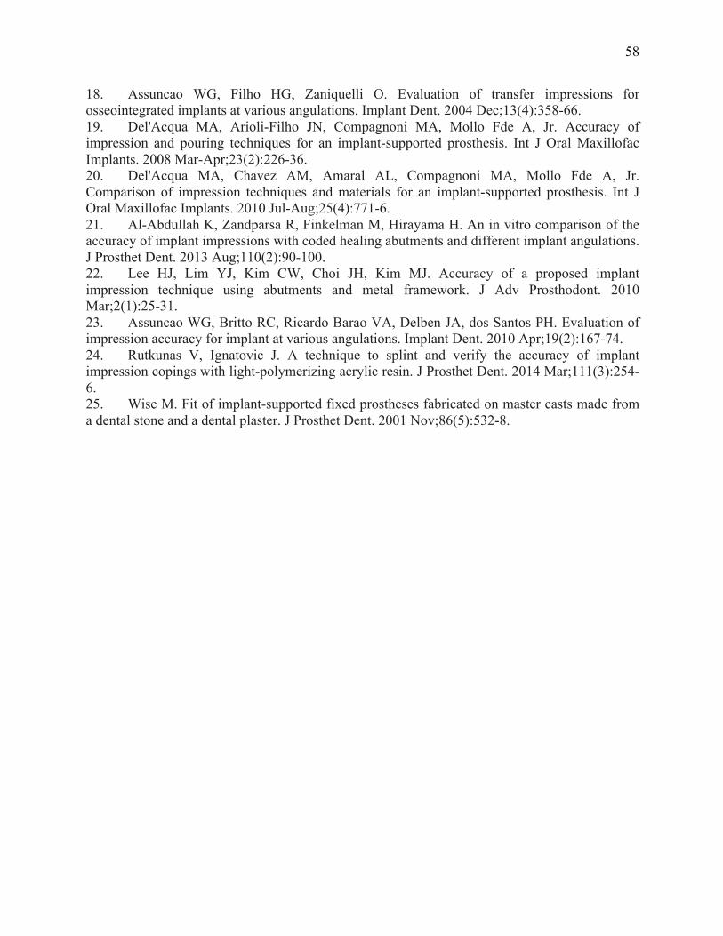
block has a lateral and circling the two mm receded, which acts as stop device for tray. (Figure 1)
Fabrication and preparation of Custom Trays
Thirty custom autopolymerizing acrylic resin trays (Jet- Clássico, Campo Limpo, SP,
Brazil) fabricated over the aluminum block were used in this study. These trays had a 3 mm
relief for impression material, with 2 spaces to allow access to the coping screws.

51
Tray polyether adhesive (3M ESPE, Seefeld, Germany) was applied thinly and evenly
over the inner surface of each tray and extended approximately 3 mm into the outer surface of
the tray, along the periphery. The adhesive was allowed to dry for 15 minutes before the
impressions were made.
Experimental desing
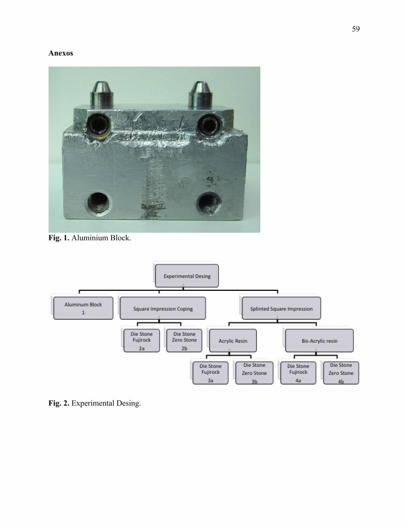
The control group was the aluminium block. Other six groups were performed according
the impression thecnique and die material (GC Fujirock EP, GC Europe, Leuven, Belgium and
Zero Stone, Dentona AG, Europe, Dortmund, Germany). (Figure 2)
Soft viscous polyether (Impregum Penta Soft; 3M ESPE, Seefeld, Germany) was the
impression material chosen for all transfer procedures. 4,17 Automatic mixing and dispenser
Pentamix 2 (3M ESPE, Seefeld, Germany) was used to standardize all mixtures. Polyether was
injected around the transfer copings and placed inside the custom tray using the dispenser. The
tray was seated on the aluminum block with gentle pressure until the lateral and circling stops
contacted the base of the aluminum block. The impression material was allowed to set for 12
minutes from the start of mixing; the manufacturer’s setting time was doubled to compensate a
delayed polymerization reaction at room temperature rather than a mouth temperature. A
standardized load of 1.25 kg was exerted over each tray during the impression procedures. 18,19
This was enough to force the excess material to flow out and to maintain constant pressure
throughout the working time.
Splinting of Transfer Copings
Groups 2a e 2b: Squared impression copings (Figure 3). The squared impression copings were
adapted to the abutment analogs on the aluminum block using 10 Ncm of torque.
Groups 3a e 3b: Splinted squared copings using dental floss and acrylic resin – Pattern (GC
Europe, Leuven, Belgium) (Figure 4). The squared impression copings were adapted to the

52
abutment analogs on the aluminum block using 10 Ncm of torque. Dental floss was adaptaded to
the squared impression copings, and the acrylic resin inserted around until polymerization.
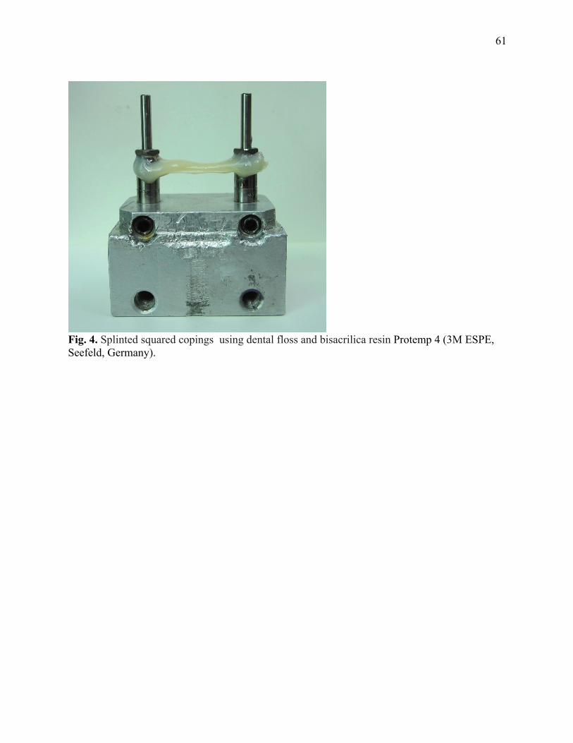
Groups 4a e 4b: Splinted squared copings using dental floss and bis-acrylic resin Protemp 4
(3M ESPE, Seefeld, Germany) (Figure 5).
Specimen Preparation
After the polymerization of the impression material, the impression copings were
unscrewed and the tray was separated from the aluminum block. The minipilar abutment analogs
(Neodent SA Curitiba, Parana , Brazil) were fited to the impression copings using 10 Ncm of
torque while the copings were held with a hemostatic forceps to prevent the squared coping from
rotating inside the impression. 20 This procedure is not necessary for the modified squared
technique, but it was performed in order to standardize the methodology.
The impressions were poured with a die stone - Type IV dental stone, GC Fujirock EP and Zero
Stone, 30 minutes after the impressions were made. A ratio of 20 mL of distilled water to 100 g
of stone was used, and the stone was mixed manually for 15 seconds to incorporate the water
and then mechanically mixed under vacuum for 45 seconds with a digital vacuum spatulator
(Turbomix EDG Equipment, São Carlos, SP, Brazil). All mixes were vibrated into the
impression. The stone casts were allowed to set two hours before separation from the
impressions.
Measurement
After 7 days, the distances between the analogs of each specimen were mesured. Ten
readings were made of the distance between the analogs Control Group - aluminum block
(Group 1) and the average was calculated - Gold Standard. For each specimen was held 4
readings of the distance between the analogues (n = 5), then the average of each sample to each
group was calculated.

53
The measurement was analyzed using software (AxionVision 4.8.1, Zeiss; Carl Zeiss,
Jena, Germany) that received the images from a camera (AxionCam ICc3, Zeiss; Carl Zeiss,
Jena, Germany) coupled to a stereomicroscope (Zeiss Discovery V20; Carl Zeiss, Jena,
Germany), observed at 10X magnification.
Statistical analysis
Data showed normal distribution of values. Shapiro-Wilk test was performed using using
SPSS/PC Statics 18 (SPSS Inc., Chicago, IL, USA) at level significance of 5%.
For the quantitative variable, parametric test (Test t) was used to compare the mean
values of the aluminum block (Group 1) to the mean values of each group.
Two way ANOVA was done to evaluate the relationship between die and impression
techniques and Post hoc analysis with Tukey.
RESULTS
Sample included 30 specimens (n =5) and one control Group - aluminum block. Table 1
shows the mean, standard deviations, minimum value, maximum value of the distance between
analogs for the different groups.
The parametric test (Test t) was used to compare the mean values of aluminum block
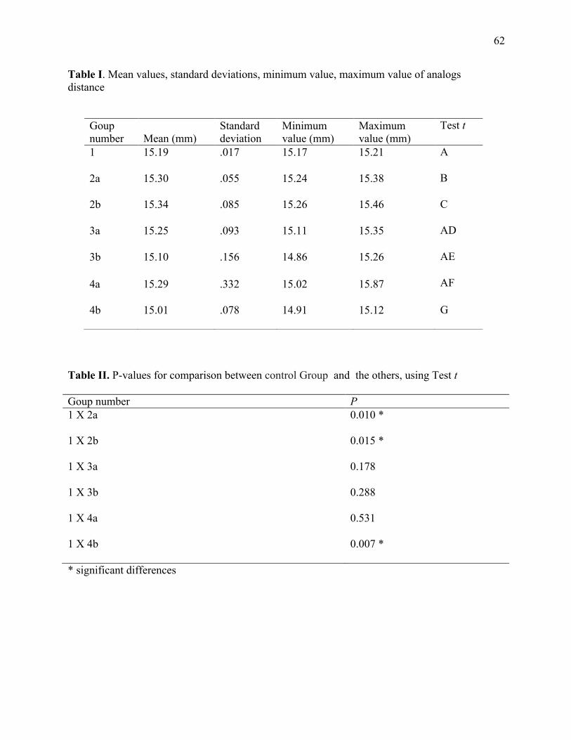
Group 1 to the mean values of each group. Statistical significant differences for groups 2a (P=
.001), 2b (P=.015) and 4b (P=.007) were found, as shown on Table 2.
It was observed one difference statistically significance between the die (P=.03) (Table 3)
and were not observed differences statistically significance among impression techniques
(P=.05) (Table 4) and interaction between die and impression techniques (P=.10).
It were not observed differences statistically significance among groups 2a, 2b, 3a, 3b, 4a,
4b (p > .05).

54
DISCUSSION
The null hypothesis of the present study, stating that the accuracy of casts would not be
affected by the impression technique and trademark of stone was rejected. Significant differences
were detected between the control group and squared impression copings technique pouring with
differences’ stones and between splinted squared copings using dental floss and bisacrilica resin
poured with a die stone Zero Stone.
An ideal impression technique would involve minimal time; be easy to use, inexpensive,
and comfortable for the patient; and, would give the most accurate results. The implant definitive
casts with CAD/CAM technology (Robocasts) from coded healing abutment impressions
represents a simpler and innovative alternative to conventional implant impression techniques,
but more studies are necessary. Al-Abdullah et al, 2013 21, evaluate the accuracy of the
Robocasts and compare them to those definitive casts fabricated with conventional implant
impression techniques (open tray with splinted impression copings technique). The implant
definitive casts fabricated from the coded healing abutment impressions seems to to be less
accurate comparing to those fabricated from the open tray, with conventional implant
impression techniques.
The splinted squared copings minimized the chance of accidental displacement of the
direct impression coping when the abutment analogs were tightened. The common practice of
joining the direct transfer copings with acrylic resin is an attempt to stabilize the copings against
rotation during analog fastening, control the relationship between implants in a rigid fashion, or
to provide a framework pattern in an expedient manner. 9 In this study the control group showed
similar results compared to the groups 3a e 3b (Splinted squared copings using dental floss and
acrylic resin and 4a (Splinted squared copings using dental floss and bisacrilica resin). These
findings are in accordance to Lee et al, 2010 22, Naconecy et al, 2004 4, Assunção et al, 2010 23,
55
who produced more accurate working casts with splinted self- curing acrylic resin technique.
Another aspect that must be considered when the modified squared technique is used is
that extra time is involved in creating the modified squared coping. It seems to be a clinical
advantage using splinting impression copings with light-polymerized composite resin to
minimize problems related to resin polymerization contraction and to avoid this time-consuming
multiple-step procedure (time required for acrylic resin polymerization and the additional step of
sectioning and rejoining the acrylic resin splint). Therefore, it improved efficiency, reduction of
visit time and greater transfer precision as a result of splinting stability. 24
Wise in 2001 25, evaluated the fit of fixed prostheses fabricated on master casts poured in
a conventional die stone and in an ultra-low-expansion plaster was investigated in vitro. An
impression was made of patient replicas with inter-implant abutment distances of 50 and 35 mm.
In this in vitro study, master casts poured in an ultra-low-expansion plaster limited to a
maximum inter-abutment dimension of 35 mm were more accurate than casts with 50-mm inter-
abutment spans or those poured in a conventional die stone. 25
For practical clinical purposes, an understanding of the magnitude and variability of
distortion when employing certain methods and materials helps the clinician to determine witch
procedures provide the best accuracy. The splinted squared copings using dental floss and acrylic
resin poured with both die stone (GC Fujirock EP and stone Zero Stone) and Splinted squared
copings using dental floss and bis-acrylic resin poured with die stone (GC Fujirock EP) showed
more similar distance between the analogs as the Control Group. These results suggests that
more accurate casts could produce a higher percentage of the time using the direct technique
(splinted squared copings) for conditions similar to the model tested.
56
CONCLUSIONS
Under the limitations of this study, the splinted squared copings using dental floss and
acrylic resin and splinted squared copings using dental floss and bis-acrylic resin (Protemp 4-
3M ESPE) poured with a die stone GC Fujirock EP produced cast most similar to the control
Group.

57
REFERENCES
1. Zarb GA, Schmitt A. The longitudinal clinical effectiveness of osseointegrated dental implants: the Toronto study. Part III: Problems and complications encountered. J Prosthet Dent. 1990 Aug;64(2):185-94. 2. Sahin S, Cehreli MC. The significance of passive framework fit in implant prosthodontics: current status. Implant Dent. 2001;10(2):85-92. 3. Lee H, So JS, Hochstedler JL, Ercoli C. The accuracy of implant impressions: a systematic review. J Prosthet Dent. 2008 Oct;100(4):285-91. 4. Naconecy MM, Teixeira ER, Shinkai RS, Frasca LC, Cervieri A. Evaluation of the accuracy of 3 transfer techniques for implant-supported prostheses with multiple abutments. Int J Oral Maxillofac Implants. 2004 Mar-Apr;19(2):192-8. 5. Del'Acqua MA, Chavez AM, Compagnoni MA, Molo Fde A, Jr. Accuracy of impression techniques for an implant-supported prosthesis. Int J Oral Maxillofac Implants. 2010 Jul-Aug;25(4):715-21. 6. Papaspyridakos P, Benic GI, Hogsett VL, White GS, Lal K, Gallucci GO. Accuracy of implant casts generated with splinted and non-splinted impression techniques for edentulous patients: an optical scanning study. Clin Oral Implants Res. 2011 Jun 2. 7. Faria JC, Silva-Concilio LR, Neves AC, Miranda ME, Teixeira ML. Evaluation of the accuracy of different transfer impression techniques for multiple implants. Braz Oral Res. 2011 Apr;25(2):163-7. 8. Hariharan R, Shankar C, Rajan M, Baig MR, Azhagarasan NS. Evaluation of accuracy of multiple dental implant impressions using various splinting materials. Int J Oral Maxillofac Implants. 2010 Jan-Feb;25(1):38-44. 9. Carr AB. Comparison of impression techniques for a five-implant mandibular model. Int J Oral Maxillofac Implants. 1991 Winter;6(4):448-55. 10. Humphries RM, Yaman P, Bloem TJ. The accuracy of implant master casts constructed from transfer impressions. Int J Oral Maxillofac Implants. 1990 Winter;5(4):331-6. 11. Choi JH, Lim YJ, Yim SH, Kim CW. Evaluation of the accuracy of implant-level impression techniques for internal-connection implant prostheses in parallel and divergent models. Int J Oral Maxillofac Implants. 2007 Sep-Oct;22(5):761-8. 12. Vigolo P, Majzoub Z, Cordioli G. Evaluation of the accuracy of three techniques used for multiple implant abutment impressions. J Prosthet Dent. 2003 Feb;89(2):186-92. 13. Del Acqua MA, Chavez AM, Castanharo SM, Compagnoni MA, Mollo Fde A, Jr. The effect of splint material rigidity in implant impression techniques. Int J Oral Maxillofac Implants. 2010 Nov-Dec;25(6):1153-8. 14. Assif D, Marshak B, Schmidt A. Accuracy of implant impression techniques. Int J Oral Maxillofac Implants. 1996 Mar-Apr;11(2):216-22. 15. Inturregui JA, Aquilino SA, Ryther JS, Lund PS. Evaluation of three impression techniques for osseointegrated oral implants. J Prosthet Dent. 1993 May;69(5):503-9. 16. Schwedhelm ER, Lepe X. Fracture strength of type IV and type V die stone as a function of time. J Prosthet Dent. 1997 Dec;78(6):554-9. 17. Lorenzoni M, Pertl C, Penkner K, Polansky R, Sedaj B, Wegscheider WA. Comparison of the transfer precision of three different impression materials in combination with transfer caps for the Frialit-2 system. J Oral Rehabil. 2000 Jul;27(7):629-38.
58
18. Assuncao WG, Filho HG, Zaniquelli O. Evaluation of transfer impressions for osseointegrated implants at various angulations. Implant Dent. 2004 Dec;13(4):358-66. 19. Del'Acqua MA, Arioli-Filho JN, Compagnoni MA, Mollo Fde A, Jr. Accuracy of impression and pouring techniques for an implant-supported prosthesis. Int J Oral Maxillofac Implants. 2008 Mar-Apr;23(2):226-36. 20. Del'Acqua MA, Chavez AM, Amaral AL, Compagnoni MA, Mollo Fde A, Jr. Comparison of impression techniques and materials for an implant-supported prosthesis. Int J Oral Maxillofac Implants. 2010 Jul-Aug;25(4):771-6. 21. Al-Abdullah K, Zandparsa R, Finkelman M, Hirayama H. An in vitro comparison of the accuracy of implant impressions with coded healing abutments and different implant angulations. J Prosthet Dent. 2013 Aug;110(2):90-100. 22. Lee HJ, Lim YJ, Kim CW, Choi JH, Kim MJ. Accuracy of a proposed implant impression technique using abutments and metal framework. J Adv Prosthodont. 2010 Mar;2(1):25-31. 23. Assuncao WG, Britto RC, Ricardo Barao VA, Delben JA, dos Santos PH. Evaluation of impression accuracy for implant at various angulations. Implant Dent. 2010 Apr;19(2):167-74. 24. Rutkunas V, Ignatovic J. A technique to splint and verify the accuracy of implant impression copings with light-polymerizing acrylic resin. J Prosthet Dent. 2014 Mar;111(3):254-6. 25. Wise M. Fit of implant-supported fixed prostheses fabricated on master casts made from a dental stone and a dental plaster. J Prosthet Dent. 2001 Nov;86(5):532-8.
59
Anexos
Fig. 1. Aluminium Block.
Fig. 2. Experimental Desing.

60
Fig. 2. Squared impression copings.
Fig. 3. Splinted squared copings using dental floss and acrylic resin – Pattern (GC Europe, Leuven, Belgium).
61
Fig. 4. Splinted squared copings using dental floss and bisacrilica resin Protemp 4 (3M ESPE, Seefeld, Germany).
62
Table I. Mean values, standard deviations, minimum value, maximum value of analogs distance
Table II. P-values for comparison between control Group and the others, using Test t
Goup number P 1 X 2a 0.010 *
1 X 2b 0.015 *
1 X 3a 0.178
1 X 3b 0.288
1 X 4a 0.531
1 X 4b 0.007 *
* significant differences
Goup number Mean (mm)
Standard deviation
Minimum value (mm)
Maximum value (mm)
Test t
1 15.19 .017 15.17 15.21 A
2a 15.30 .055 15.24 15.38 B
2b 15.34 .085 15.26 15.46 C
3a 15.25 .093 15.11 15.35 AD
3b 15.10 .156 14.86 15.26 AE
4a 15.29 .332 15.02 15.87 AF
4b 15.01 .078 14.91 15.12 G
63
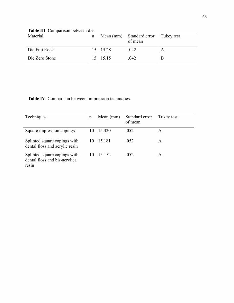
Table III. Comparison between die. Material n Mean (mm) Standard error
of mean Tukey test
Die Fuji Rock 15 15.28 .042 A
Die Zero Stone 15 15.15 .042 B
Table IV. Comparison between impression techniques.
Techniques n Mean (mm) Standard error of mean
Tukey test
Square impression copings 10 15.320 .052 A
Splinted square copings with dental floss and acrylic resin
10 15.181 .052 A
Splinted square copings with dental floss and bis-acrylica resin
10 15.152 .052 A

64
DISCUSSÃO GERAL
65
DISCUSSÃO GERAL
Os modelos de trabalho reproduzem a posição intraoral dos implantes em torno dos
tecidos duros e moles buscando sempre a maior precisão possível, para permitir o assentamento
passivo das próteses sobre ele fabricadas e, consequentemente eliminando a tensão sobre os
componentes de suporte e ao redor do osso (20).
O assentamento passivo é um dos pré-requisitos mais importantes na reabilitação oral
sobre implantes e na manutenção da osseointegração. O assentantamento passivo ocorre quando
todas as superfícies, do implante e prótese são alinhadas sem aplicação de força. Diversos
trabalhos clínicos e laboratoriais buscam definir qual o valor que seria aceitável para um assento
passivo ideal. Em 1991, Jemt (21) definiu ajuste passivo como um nível que não causou
nenhuma complicação clínica a longo prazo e sugeriu que maus assentamentos menores que
150µm eram aceitáveis. Entretanto, Jemt e Book, (1996) (22) avaliaram dois grupos de sete
pacientes cada, sendo o primeiro grupo com um ano de avaliação, apresentando gap médio de
111µm e um segundo com cinco anos de observação e gap médio de 91µm foram avaliadas. Não
houve diferença significativa entre a perda óssea marginal média observada radiograficamente
entre os dois grupos (0,5 mm e 0,2 mm respectivamente). Os autores concluíram que, para o
nível de desadaptação apresentado no estudo, pareceu ter havido uma certa tolerância biológica e
o nível de perda óssea foi clinicamente aceitável. Tan et al., (1993) (23) e Kan, (1999) (24)
sugerem que a percepção visual em conjunto com sensação tátil através de uma sonda
exploradora é um método comumente utilizado para avaliar o ajuste da estrutura do implante,
sendo a sensibilidade desta técnica limitada pelo tamanho da ponta da sonda, a localização da
borda e a capacidade discriminatória do clínico. A ponta de uma sonda nova é de
aproximadamente 60µm, tomando um mau assentamento de menor dimensão que esta difícil de
detectar.

66
O bloco de aluminio possuiu como valores médios de gap entre os analogos e a
infraestrutura valores de 60 µm (implante 65°) e 30 µm (implante inclinado a 90 graus). Valores
estes aceitaveis na literatura como a assentamento passivo ideal. O maior valor encontrado neste
estudo foi de 510 µm (Técnica de moldagem de arrasto sem união dos components e implante
inclinado a 65 graus), sendo este último considerado como valor inaceitável de assentamento
passivo.
Diferentes técnicas de moldagem buscam reproduzir a posição intraoral dos implantes.
A não observância de consenso sobre as técnicas de moldagens faz que a pesquisa continue
sempre se aperfeiçoando. O surgimento de novos materiais e técnicas implicam no surgimento de
novas pesquisas laboratoriais e clinicas.
A literature cientifica apresenta duas técnicas de moldagem, que são as técnicas de
transferência (transfer) e a de arrasto ou sacar (pick up).
Na técnica de transferência (casquete cônico) utiliza-se moldeiras fechadas, transferentes
cônicos que possibilitam a sua permanencia na cavidade bucal após a remoção do molde, esta
apresenta uma menor precisão (25-27).
A moldagem de arrasto utiliza moldeira aberta e transferes quadrados, estes possuem
paredes paralelas e áreas retentivas para que fiquem capturados no interior do molde sem se
movimentarem. Existe a possibilidade de girar os componentes no interior do molde, quando se
parafusa a replica ou analogo, assim a união dos tranferentes e esplintagem dos componentes
tem sido muito bem defendida em diversos trabalhos para moldagem de próteses sobre implantes
múltiplos (6, 28) (8) (10). Ao compararmos as técnicas de moldagem de arrasto sem união e
com união em resina acrilica para implantes não paralelos encontramos diferenças entre os
grupos, sendo maiores valores de gap para o grupo sem união 280 µm (P=0.021). Estes
resultados estão de acordo com os trabalhos Naconecy et al 2004, Lee et al 2010 (18, 29) na qual
67
defendem a união para minimizar a possibilidade de girar os componentes no interior do molde,
quando se parafusa a replica ou analogo.
Ainda ao compararmos separadamente os valores de gap entre os analogos (A e B) e
infraestrutura, obtivemos maiores valores para o implante B (inclinado) no grupo Técnica de
moldagem de arrasto sem união dos componentes (510 µm). Valores estes de acordo com
trabalhos de Carr et al (1991) (27) e Akalin et al. 2013 (30) na qual concluiram que a
desadaptação parece estar relacionada com a ausencia de paralelismo entre os implantes.
Outra etapa para a confecção das próteses implanto suportadas é a obtenção dos modelos.
O material mais comumente utilizado para modelos e troqueis é o gesso odontológico.
Segundo McCartney e Pearson, (1994) (31) e Del ́Acqua et al., (2008) (32), a expansão
do gesso durante a presa também pode causar desadaptação. No início da cristalização, ocorre
ligeira expansão de 0,1% a 0,05%. Mesmo para o poliéter que possui uma boa rigidez, essa
expansão de cristalização do gesso pode gerar falha. No artigo 2 tivemos como uma das variaveis
diferentes marcas comercias de gesso tipo IV, sendo elas o GC Fujirock EP (GC Europa,
Leuven, Belgica) e Zero Stone (Dentona AG, Europa, Dortmund, Alemanha). O gesso Zero
Stone segundo fabricante possui zero de expansão, assim tentou-se verificar se hipotese de que
os modelos de gesso confeccionados com este material seriam mais precisos que os
confecionados com outra marca de gesso. Os resultados mostraram diferenças significantes entre
os gessos.
Ao compararmos três diferentes técnicas de moldagem para implantes paralelos
(moldagem de arrasto, moldagem de arrasto com união em resina acrilica e moldagem de arrasto
com união em resina bisacrilica nanoparticulada) e duas diferentes marcas comercias de gesso
(GC Fujirock EP; GC Europa, Leuven, Belgica e Dentona AG, Europa, Dortmund, Alemanha)
para obtenção dos modelos de trabalho, os resultados mostraram algumas diferenças quando

68
compardos com o bloco de alumínio (padrão).
Na moldagem de arrasto ou de sacar (pick up) pode-se realizar a união dos transferes
quadrados com diferentes materiais. Na literatura encontramos os seguinte materiais: fio dental +
resina acrílica R.A. (DuraLay, Reliance, Illinois, EUA), fio dental + RA (Pattern - GC Europe,
Leuven, Belgica) (6), RA com extensão nas distais para retenção (7), RA com espera de 17 min,
tempo de maior contração, secção e nova união (8), resina acrilica de dupla polimerização
(AccuSet -EDS,. Hackensack, NJ) –Assif et al 1999 (9), RA fotopolimerizada (lâminas de resina
acrilica) (10), barras pré polimerizadas (RA ou resina composta) (10), resina polimerizada por
luz, fios de ortodontia + RA, silicona de condensação, gesso tipo I para moldagem (11),
jateamento dos tranferentes e aplicação do adesivo do poliéter (7). A resina acrílica
autopolimerizavel é um dos materiais com ótimos resultados mais utilizado nestes estudos (6, 7,
12, 13, 33). Uma das desvantagens apresentadas deste material é a alta contração de
polimerização. Outro aspecto que deve ser considerado quando a técnica de arrasto é utilizada é
o tempo extra envolvido na união dos transferentes quadrado. Parece haver uma vantagem
clínica na união com resina polimerizada por luz por esta minimizar problemas relacionados com
a contração da polimerização da resina e pela diminuição do tempo consumido nesta etapa
(tempo requerido para a polimerização da resina). As resinas bisacrilicas são materiais
desenvolvidos para minimizar os efeitos negativos da resina acrílica, além de ser mais fácil de
usar, devido possuir um cartucho automisturador, na qual já nos dá as proporções corretas,
possui menor contração de polimerização e maior resistência.
Neste estudo utilizamos diferentes materiais de união dos componentes quadrados e
comparamos com o grupo controle. Os resultados mostraram que o grupo de controle foi
semelhantes aos grupos 3a e 3b (componente quadrado unidos com fio dental e resina acrílica e
4a (componente quadrado unidos com fio dental e resina bisacrilica). Estes resultados estão de

69
acordo com Lee et al , 2010 (18) , Naconecy et al, 2004(29) , Assunção et al , 2010(34) , que
produziram modelos de trabalho mais precisos quando unidos com resina acrilica
autopolimerizavel.
Para fins de propositos clinico, uma compreensão da magnitude e variabilidade das
distorções quando empregados certos metodos e materiais para moldagem de implantes
multiplos ajudam o clinico a determinar quais procedimentos que promovem uma melhor
exatidão na obtenção dos modelo de trabalho. Nesse sentido, espera-se que o conjunto de
resultados do presente estudo possa contribuir para o desenvolvimento de estratégias futuras para
o aprimoramento das técnicas de moldagem de implantes multiplos e etapas laboratoriais, para
que tenhamos modelos de trabalho fiéis para a confecção das próteses sobre implantes
osseointegraveis.

70
CONCLUSÕES
71
CONCLUSÕES
A partir dos resultados do presente estudo pode-se concluir que:
1. Os modelos de gesso obtidos a partir da técnica de arrasto sem união dos componentes
apresentaram maiores discrepâncias do que aqueles obtidos a partir da técnica de sacar com
união dos componentes com resina acrílica, quando utilizados implantes inclinados.
2. Os implantes angulados (65°) mostraram maiores valores de gap que implantes os
perpendicular a superfície.
3. Os modelos de gesso obtidos a partir das técnicas de arrasto sem união, com união em
Resina Acrílica e com união em resina bisacrílica não mostraram diferenças estatisticamente
significantes.
4. Os modelos de gesso obtidos por diferentes marcas comerciais mostraram diferenças
significantes.
72
REFERÊNCIAS 1. Silva MM, Mima EGO, Del'Acqua MA, Segala JCM, Silva RHBT, Pinelli LAP. Técnicas de moldagem em prótese sobre implantes. Revista de Odontologia da UNESP. 2008;37(4):301-8. 2. Sahin S, Cehreli MC. The significance of passive framework fit in implant prosthodontics: current status. Implant Dent. 2001;10(2):85-92. 3. Assuncao WG, Cardoso A, Gomes EA, Tabata LF, dos Santos PH. Accuracy of impression techniques for implants. Part 1--Influence of transfer copings surface abrasion. J Prosthodont. 2008 Dec;17(8):641-7. 4. Papaspyridakos P, Lal K, White GS, Weber HP, Gallucci GO. Effect of splinted and nonsplinted impression techniques on the accuracy of fit of fixed implant prostheses in edentulous patients: a comparative study. Int J Oral Maxillofac Implants. 2011 Nov-Dec;26(6):1267-72. 5. Papaspyridakos P, Benic GI, Hogsett VL, White GS, Lal K, Gallucci GO. Accuracy of implant casts generated with splinted and non-splinted impression techniques for edentulous patients: an optical scanning study. Clin Oral Implants Res. 2011 Jun 2. 6. Cho GC, Chee WW. Efficient soldering index materials for fixed partial dentures and implant substructures. J Prosthet Dent. 1995 May;73(5):424-7. 7. Del'Acqua MA, Chavez AM, Amaral AL, Compagnoni MA, Mollo Fde A, Jr. Comparison of impression techniques and materials for an implant-supported prosthesis. Int J Oral Maxillofac Implants. 2010 Jul-Aug;25(4):771-6. 8. Cabral LM, Guedes CG. Comparative analysis of 4 impression techniques for implants. Implant Dent. 2007 Jun;16(2):187-94. 9. Assif D, Nissan J, Varsano I, Singer A. Accuracy of implant impression splinted techniques: effect of splinting material. Int J Oral Maxillofac Implants. 1999 Nov-Dec;14(6):885-8. 10. Rodrigues RA, Rodrigues RQF, Barros HP, Dias AHM, Batista AUD. Avaliação in vitro entre diferentes técnicas e métodos de união de transferentes de moldagem utilizados na implantododntia. Pesq Bras Odontoped Clin Integr. 2010;10(2):285-90. 11. Inturregui JA, Aquilino SA, Ryther JS, Lund PS. Evaluation of three impression techniques for osseointegrated oral implants. J Prosthet Dent. 1993 May;69(5):503-9. 12. Assuncao WG, Delben JA, dos Santos PH, Tabata LF, Gomes EA, Barao VA. Evaluation of a two-step pouring technique for implant-supported prostheses impression. Acta Odontol Latinoam. 2010;23(1):8-12. 13. Del'Acqua MA, Chavez AM, Compagnoni MA, Molo Fde A, Jr. Accuracy of impression techniques for an implant-supported prosthesis. Int J Oral Maxillofac Implants. 2010 Jul-Aug;25(4):715-21. 14. Anusavice KJ. Philips materiais dentários. In: Koogan G, editor. Philips materiais dentários. 10 ed ed. Rio de Janeiro1998. p. 111-39. 15. Schwedhelm ER, Lepe X. Fracture strength of type IV and type V die stone as a function of time. J Prosthet Dent. 1997 Dec;78(6):554-9. 16. Vermilyea SG, Huget EF, Wiskoski J, 2nd. Evaluation of resin die materials. J Prosthet Dent. 1979 Sep;42(3):304-7. 17. Campbell SD, Riley EJ, Sozio RB. Evaluation of a new epoxy resin die material. J Prosthet Dent. 1985 Jul;54(1):136-40.

73
18. Lee HJ, Lim YJ, Kim CW, Choi JH, Kim MJ. Accuracy of a proposed implant impression technique using abutments and metal framework. J Adv Prosthodont. 2010 Mar;2(1):25-31. 19. Choi JH, Lim YJ, Yim SH, Kim CW. Evaluation of the accuracy of implant-level impression techniques for internal-connection implant prostheses in parallel and divergent models. Int J Oral Maxillofac Implants. 2007 Sep-Oct;22(5):761-8. 20. Avila ED, Moraes FD, Castanharo SM, Del Acqua MA, Mollo Junior FA. Effect of Splinting in Accuracy of Two Implant Impression Techniques. J Oral Implantol. 2012 Oct 26. 21. Jemt T. Failures and complications in 391 consecutively inserted fixed prostheses supported by Branemark implants in edentulous jaws: a study of treatment from the time of prosthesis placement to the first annual checkup. Int J Oral Maxillofac Implants. 1991 Fall;6(3):270-6. 22. Jemt T, Book K. Prosthesis misfit and marginal bone loss in edentulous implant patients. Int J Oral Maxillofac Implants. 1996 Sep-Oct;11(5):620-5. 23. Tan KB, Rubenstein JE, Nicholls JI, Yuodelis RA. Three-dimensional analysis of the casting accuracy of one-piece, osseointegrated implant-retained prostheses. Int J Prosthodont. 1993 Jul-Aug;6(4):346-63. 24. Kan JY, Rungcharassaeng K, Bohsali K, Goodacre CJ, Lang BR. Clinical methods for evaluating implant framework fit. J Prosthet Dent. 1999 Jan;81(1):7-13. 25. Humphries RM, Yaman P, Bloem TJ. The accuracy of implant master casts constructed from transfer impressions. Int J Oral Maxillofac Implants. 1990 Winter;5(4):331-6. 26. Herbst D, Nel JC, Driessen CH, Becker PJ. Evaluation of impression accuracy for osseointegrated implant supported superstructures. J Prosthet Dent. 2000 May;83(5):555-61. 27. Carr AB. Comparison of impression techniques for a five-implant mandibular model. Int J Oral Maxillofac Implants. 1991 Winter;6(4):448-55. 28. Del Acqua MA, Chavez AM, Castanharo SM, Compagnoni MA, Mollo Fde A, Jr. The effect of splint material rigidity in implant impression techniques. Int J Oral Maxillofac Implants. 2010 Nov-Dec;25(6):1153-8. 29. Naconecy MM, Teixeira ER, Shinkai RS, Frasca LC, Cervieri A. Evaluation of the accuracy of 3 transfer techniques for implant-supported prostheses with multiple abutments. Int J Oral Maxillofac Implants. 2004 Mar-Apr;19(2):192-8. 30. Akalin ZF, Ozkan YK, Ekerim A. Effects of implant angulation, impression material, and variation in arch curvature width on implant transfer model accuracy. Int J Oral Maxillofac Implants. 2013 Jan-Feb;28(1):149-57. 31. McCartney JW, Pearson R. Segmental framework matrix: master cast verification, corrected cast guide, and analog transfer template for implant-supported prostheses. J Prosthet Dent. 1994 Feb;71(2):197-200. 32. Del'Acqua MA, Arioli-Filho JN, Compagnoni MA, Mollo Fde A, Jr. Accuracy of impression and pouring techniques for an implant-supported prosthesis. Int J Oral Maxillofac Implants. 2008 Mar-Apr;23(2):226-36. 33. Assuncao WG, Gomes EA, Aparecida Delben J, dos-Santos PH, Ricardo Barao VA, Tabata LF. An implant-transfer technique without impression material. J Craniofac Surg. 2010 Jul;21(4):1274-6. 34. Assuncao WG, Britto RC, Ricardo Barao VA, Delben JA, dos Santos PH. Evaluation of impression accuracy for implant at various angulations. Implant Dent. 2010 Apr;19(2):167-74.

74
ANEXOS
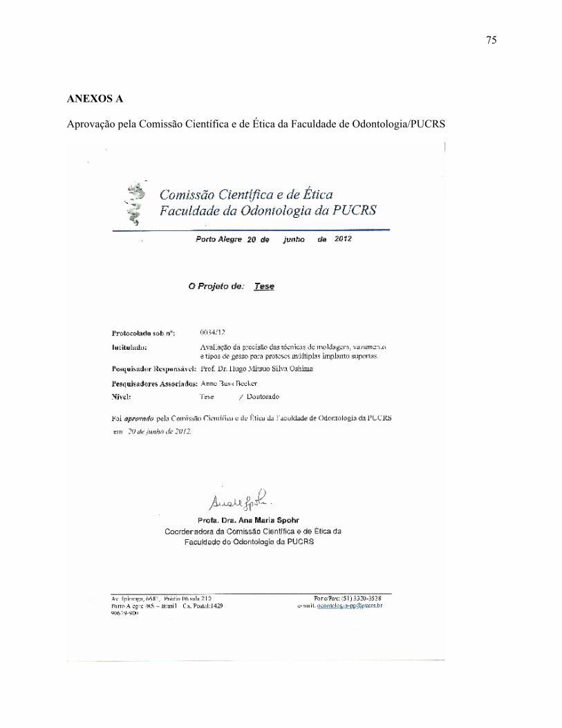
75
ANEXOS A
Aprovação pela Comissão Científica e de Ética da Faculdade de Odontologia/PUCRS

76
ANEXOS B
Normas do Periódico Journal of Prosthetic Dentistry
Thank you for your interest in writing an article for The Journal of Prosthetic Dentistry. In publishing, as in dentistry, precise procedures are essential. Your attention to and compliance with the following policies will help ensure the timely processing of your submission.
Length of Manuscripts Manuscript length depends on manuscript type. In general, research and clinical science articles should not exceed 10 to 12 double-spaced, typed pages (excluding references, legends, and tables). Clinical Reports and Technique articles should not exceed 4 to 5 pages, and Tips articles should not exceed 1 to 2 pages. The length of systematic reviews varies.
Number of Authors The number of authors is limited to 4; the inclusion of more than 4 must be justified in the letter of submission. (Each author’s contribution must be listed.) Otherwise, contributing authors in excess of 4 will be listed after the references.
General Formatting All submissions must be typed in Word or a Word-compatible 8.5x11” document; printed on 1 side only. The following specifications should also be followed:
• Times Roman, 12 pt • Double-spaced • Left-justified • 1-inch margins on all sides • Half-inch tabs • Headers/Footers should be clear of page numbers or other information • References should not be automatically numbered (formatted).
Hard Copy and Electronic Files Please submit an electronic file of the text and tables on a CD. Microsoft Word is the preferred word processing program. Without an electronic copy of the text and tables, we cannot submit the manuscript to our review process. High quality illustrations in TIF format must be submitted upon initial submission (see pages 11-13 for more information). Paper copies of the document and figures are not necessary.
Submission Guidelines

77
Copyright Transfer In accordance with the Copyright Act of 1976, all manuscripts must be accompanied by a Copyright Transfer/IRB Approval/HIPAA Compliance Statement signed by EACH author individually. (Appendix, page 19). One statement should be received from each author—only the signing author’s name should appear on the form.) If a manuscript number has been assigned, it should be included at the end of the statement. Articles are classified as one of the following: research/clinical science article, clinical report, technique article, systematic review, or tip from our readers. Required sections for each type of article are listed in the order in which they should be presented.
RESEARCH REPORT / CLINICAL STUDY The research report should be no longer than 10-12 double-spaced, typed pages and be accompanied by no more than 12 high-quality illustrations.
• Abstract (approximately 250 words): Create a structured abstract with the following subsections: Statement of Problem, Purpose, Material and Methods, Results, and Conclusions. The abstract should contain enough detail to describe the experimental design and variables. Sample size, controls, method of measurement, standardization, examiner reliability, and statistical method used with associated level of significance should be described in the Material and Methods section. Actual values should be provided in the Results section.
• Clinical Implications: In 2-4 sentences, describe the impact of the study results on clinical practice.
• Introduction: Explain the problem completely and accurately. Summarize relevant literature, and identify any bias in previous studies. Clearly state the objective of the study and the research hypothesis at the end of the Introduction. Please note that, for a thorough review of the literature, most (if not all references) should first be cited in the Introduction and/or Material and Methods section.
• Material and Methods: In the initial paragraph, provide an overview of the experiment. Provide complete manufacturing information for all products and instruments used, either in parentheses or in a table. Describe what was measured, how it was measured, and the units of measure. List criteria for quantitative judgment. Describe the experimental design and variables, including defined criteria to control variables, standardization of testing, allocation of specimens/subjects to groups (specify method of randomization), total sample size, controls, calibration of examiners, and reliability of instruments and examiners. Statistical tests and associated significance levels should be described at the end of this section.
Types of Articles
78
• Results: Report the results accurately and briefly, in the same order as the testing was described in the Material and Methods section. For extensive listings, present data in tabular or graphic form to help the reader. Describe the most significant findings and trends. Text, tables, and figures should not repeat each other. Results noted as significant must be validated by actual data and P values.
• Discussion: Discuss the results of the study in relation to the hypothesis and to relevant literature. If the results do not agree with other studies and/or with accepted opinions, state how and why the results differ. Agreement with other studies should also be stated. Identify the limitations of the present study, and suggest areas for future research.
• Conclusions: Concisely list conclusions that may be drawn from the research; do not simply restate the results. The conclusions must be pertinent to the objectives and justified by the data. In most situations, the conclusions are true for only the population of the experiment. All statements reported as conclusions should be accompanied by statistical analyses.
• References: See page 9 for guidelines; page 22 for a sample References page. • Tables: Create tables in accordance with the guidelines on page 11. • Legends for illustrations: Concisely describe each illustration without directly
duplicating the main text. See page 13 for guidelines; page 23 for sample Legends page.
CLINICAL REPORT The clinical report describes the author’s methods for meeting a patient treatment challenge. It should be no longer than 4 to 5 double-spaced, typed pages and be accompanied by no more than 8 high-quality illustrations. In some situations, the Editor may approve the publication of additional figures if they contribute significantly to the manuscript.
• Abstract: Provide a short, nonstructural, 1-paragraph abstract that briefly summarizes the problem encountered and treatment administered.
• Introduction: Summarize literature relevant to the problem encountered. Include references to standard treatments and protocols. Please note that most, if not all, references should first be cited in the Introduction and/or Clinical Report section.
• Clinical Report: Describe the patient, the problem with which he/she presented, and any relevant medical or dental background. Describe the various treatment options and the reasons for selection of the chosen treatment. Fully describe the treatment rendered, the length of the follow-up period, and any improvements noted as a result of treatment. This section should be written in past tense and in paragraph form.
• Discussion: Comment on the advantages and disadvantages of the chosen treatment, and describe any contraindications for it. If the text will only be repetitive of previous sections, omit the Discussion.
• Summary: Briefly summarize the patient treatment. • References: Select and format references in accordance with the guidelines on page 10. • Legends for illustrations: Concisely describe each illustration without directly
duplicating the main text.
79
DENTAL TECHNIQUE The dental technique article presents, in a step-by-step format, a unique procedure helpful to dental professionals. It should be no longer than 4 to 5 double-spaced, typed pages and be accompanied by no more than 8 high-quality illustrations. In some situations, the Editor may approve the publication of additional figures if they contribute significantly to the manuscript.
• Abstract: Provide a short, nonstructured, 1-paragraph abstract that briefly summarizes the technique.
• Introduction: Summarize relevant literature. Include references to standard methods and protocols. Please note that most, if not all, references should first be cited in the Introduction and/or Technique section.
• Technique: In a numbered, step-by-step format, describe each step of the technique. The text should be written in command rather than descriptive form (eg, “Survey the diagnostic cast” rather than “The diagnostic cast is surveyed.”) Include citations for the accompanying illustrations.
• Discussion: Comment on the advantages and disadvantages of the technique indicate the situations to which it may be applied, and describe any contraindications for its use. Avoid excessive claims of effectiveness. If the text will only be repetitive of previous sections, omit the Discussion.
• Summary: Briefly summarize the technique presented and its chief advantages. • References: Select and format references in accordance with the guidelines on page 12. • Legends for illustrations: Concisely describe each illustration without directly
duplicating the main text.
SYSTEMATIC REVIEW The author is advised to develop a systematic review in the Cochrane style and format. The Journal is transitioning away from literature reviews to systematic reviews. For more information on systematic reviews, please see www.cochrane.org. An example of a Journal systematic review:
Torabinejad M, Anderson P, Bader J, Brown LJ, Chen LH, Goodacre CJ, Kattadiyil MT, Kutsenko D, Lozada J, Patel R, Petersen F, Puterman I, White SN. Outcomes of root canal treatment and restoration, implant-supported single crowns, fixed partial dentures, and extraction without replacement: a systematic review. J Prosthet Dent 2007 Oct;98(4):285-311.
The systematic review consists of:
1) An Abstract - using a structured format (Statement of Problem, Purpose, Material and Methods, Results, Conclusions).
2) Text of the review - consisting of an introduction (background and objective), methods
(selection criteria, search methods, data collection and data analysis), results (description of studies, methodological quality, and results of analyses), discussion, authors’

80
conclusions, acknowledgements, and conflicts of interest. References should be peer-reviewed and follow JPD format (page 11).
3) Tables and figures, if necessary—showing characteristics of the included studies,
specification of the interventions that were compared, the results of the included studies, a log of the studies that were excluded, and additional tables and figures relevant to the review.
81
TIPS FROM OUR READERS Tips are brief reports on helpful or timesaving procedures. They should be limited to 2 authors, no longer than 250 words, and include no more than 2 high quality illustrations. Place the procedure in a numbered, step-by-step format; place the text in command rather than descriptive or passive form (eg, “Survey the diagnostic cast” rather than “The diagnostic cast is surveyed”).
FIRST PAGE ARRANGEMENT –TITLE PAGE Please see a sample title page in Appendix II (page 20.)
• Title: The title should define the study’s scope, content, and clinical significance. Capitalize only the first letter of the first word. Do not underline the title or bold it. Abbreviations or trade names should not be used in the title.
• Authors: Directly under the title, type the names and degrees of the authors. List academic degrees only. No fellowship designations, please.
• Institution(s): Directly under the authors’ names, type their individual institutional affiliations and the cities, states, and countries (if not the United States) in which these institutions are located. If necessary, provide the English translation of the name of the institution. If the authors are not affiliated with an institution, please list the city, state, and country (if not the United States) in which the authors live.
• Presentation/support information and titles: If the research was presented before an organized group, type the name of the organization and the location and date of the meeting. If the work was supported by a grant or any other kind of funding, supply the name of the supporting organization and the grant number. List the academic titles (eg, Assistant Professor) and departmental affiliations of all authors.
• Contact information: List the mailing address, business telephone, fax number, and e-mail address of the author who will receive correspondence.
ABSTRACT
• The abstract must be typed on a page separate from the main text. • The abstract should not include abbreviations or manufacturing information.
MAIN TEXT Headings
• Headings should contribute to the clarity of the article and indicate a shift from one section to another (eg, Discussion to Conclusions).
Formatting Instructions

82
• The use of subheadings may be appropriate in the Material and Methods section but is generally discouraged in the Results and Discussion.
• All headings should be typed flush with the left margin. Main headings (eg, MATERIAL AND METHODS) should be in capital letters; subheadings (eg, Specimen preparation) should be in “Sentence case”; the first letter should be capitalized and the remainder of the phrase should be in lowercase.
Identification of product and manufacturing information • Refer to products in generic terms. Immediately following the term, provide the
following information in parentheses: product name and manufacturer’s name, city, state, and country (if not the United States). For example: “The impressions were poured in type IV stone (Denstone; Heraeus Kulzer, South Bend, Ind) and related to each other with a fast-setting vinyl polysiloxane occlusal registration material (Correct VPS Bite Registration; Jeneric/Pentron, Inc, Wallingford, Conn).” If the same manufacturer is cited multiple times, the city and state/country are required only in the first citation.
• Use generic drug names; trade names may be listed in parentheses at the point of first mention.
Abbreviations • If abbreviations are used, provide the expanded form upon first mention and abbreviate
thereafter; for example, “fixed partial denture (FPD)”.
REFERENCES Acceptable references and their placement
• Most, if not all, references should first be cited in the Introduction and/or Material and Methods section. Only those references that have been previously cited or that relate directly to the outcomes of the present study may be cited in the Discussion.
• Only peer-reviewed, published material may be cited as a reference. Manuscripts in preparation, manuscripts submitted for consideration, and unpublished theses are not acceptable references.
• Abstracts are considered unpublished observations and are not allowed as references unless follow-up studies were completed and published in peer-reviewed journals.
• References to foreign language publications should be kept to a minimum (no more than 3). They are permitted only when the original article has been translated into English. The translated title should be cited and the original language noted in brackets at the end of the citation.
• Textbook references should be kept to a minimum, as textbooks often reflect the opinions of their authors and/or editors. The most recent editions of textbooks should be used. Evidence-based journal citations are preferred.

83
Reference formatting • References must be identified in the body of the article with superscript Arabic numerals.
At the end of a sentence, the reference falls after the period. • The complete reference list, double spaced and in numerical order, should follow the
Conclusions section but start on a separate page. Only references cited in the text should appear in the reference list.
• Reference formatting should conform to Vancouver style as set forth in “Uniform Requirements for Manuscripts Submitted to Biomedical Journals” (Ann Intern Med 1997;126:36-47).
• References should be manually numbered. • List up to six authors. If there are seven or more, after the sixth author’s name, add et al. • Abbreviate journal names per the Cumulative Index Medicus. A complete list of
standard abbreviations is available through the PubMed website: http://www.ncbi.nlm.nih.gov/entrez/query.fcgi
• Format for journal articles: Supply the last names and initials of all authors; the title of the article; the journal name; and the year, volume, and page numbers of publication. Do not use italics, bold, or underlining for any part of the reference. Put a period after the initials of the last author, after the article title, and at the end of the reference. Put a semi-colon after the year of publication and a colon after the volume. Issue numbers are not used in Vancouver style. Ex: Jones ER, Smith IM, Doe JQ. Uses of acrylic resin. J Prosthet Dent 1985;53:120-9.
• Book References: The most current edition must be cited. Supply the names and initials
of all authors/editors, the title of the book, the city of publication, the publisher, the year of publication, and the inclusive page numbers consulted. Do not use italics, bold, or underlining for any part of the reference.
Ex: Zarb GA, Carlsson GE, Bolender CL. Boucher’s prosthodontic treatment for edentulous patients. 11th ed. St. Louis: Mosby; 1997. p. 112-23. Note: References should not be submitted in Endnotes. Endnotes formatting cannot be edited by the Editorial Office or reviewers, and must be suppressed or removed from the manuscript prior to submission. Nor should references be automatically numbered.
TABLES
• Tables should be self-explanatory and should supplement, not duplicate, the text. • Provide all tables at the end of the manuscript, after the reference list and before the
Legends. There should be only one table a page. Omit internal horizontal and vertical rules (lines). Omit any shading or color.
• Do not list tables in parts (eg, Table Ia, Ib, etc.). Each should have its own number. Number the tables in the order in which they are mentioned in the text.

84
• Supply a concise legend that describes the content of the table. Create descriptive column and row headings. Within columns, align data such that decimal points may be traced in a straight line. Use decimal points, not commas, to mark places past the integer (eg, 3.5 rather than 3,5).
• In a line beneath the table, define any abbreviations used in the table. • If a table (or any data within it) was published previously, give full credit to the original
source in a footnote to the table. If necessary, obtain permission to reprint from the author/publisher.
• The tables should be submitted in Microsoft Word, or Word-compatible format. Microsoft Word is preferred. If a table has been prepared in Excel, it should be imported into one of the abovementioned formats prior to submission.
File Type All figures should be submitted as Tagged Image File Format (TIFF) files. Figures should NOT be submitted as Microsoft Word, Corel Draw, Harvard Graphics, PowerPoint, or other presentation software formats. Line art and combination artwork is best created in native design format, such as EPS (Encapsulated PostScript), Adobe Illustrator, InDesign, etc., but should be saved as a TIF prior to submission to the Journal. Image File Specifications Figure dimensions must be a minimum of 4 × 6 inches. Figures should be size-matched (the same physical size), unless the image type prohibits size-matching to other figures within the manuscript, as in the case of panoramic or periapical radiographs, SEM images, graphs and screen shots. Do not “label” the faces of the figures with letters or numbers to indicate the order in which the figures should appear; such labels will be inserted during the publication process. Resolution The figures should be of professional quality and high resolution. The following are resolution guidelines:
• Color and black-and-white photographs should be created and saved at a minimum of 300 dots per inch (dpi). (Note: A 4 × 6-inch image at a resolution of 300 dpi will be approximately 6 megabytes. A figure of less than 300 dpi must not be increased artificially to 300 dpi; the resulting quality and resolution will be poor.
• Line art should be created and saved as 1200 dpi.
Electronic Image Submission

85
• Combination artwork (an illustration containing both line art and photograph) should be created and saved as 600 to 1000 dpi.
• Clarity, good contrast and quality should be uniform among the parts of a multipart figure, and among all of the figures within a manuscript.
• Composite figures (multiple images combined into a single frame) are unacceptable. Each image part should be a separate 4 × 6-inch, 300-dpi image.
• A uniform background, a nontextured, medium blue, should be provided for color figures when possible.
Text within Images If text is to appear within the figure, labeled and unlabeled versions of the figures must be provided. Text appearing within the labeled versions of the figures should be in Ariel font and a minimum of 10 pt. The text should be sized for readability if the figure is reduced for production in the Journal. Lettering should be in proportion to the drawing, graph, or photograph. A consistent font size should be used throughout each figure, and for all figures, Please note: Titles and captions should not appear within the figure file, but should be provided in the manuscript text (see Figure Legends, below). If a key to an illustration requires artwork (screen lines, dots, unusual symbols), the key should be incorporated into the drawing instead of included in the typed legend. All symbols should be done professionally, be visible against the background, and be of legible proportion should the illustration be reduced for publication. All microscopic photographs must have a measurement bar and unit of measurement on image. Color Figures Color illustrations may be submitted when their use considerably enhances the value of the manuscript. The Editor has final authority to determine whether color illustrations provide the most effective presentation. Generally, a maximum of 8 figures will be accepted for clinical report and dental technique articles, and 2 figures will be accepted for tips from our reader articles. However, the Editor may approve the publication of additional figures if they contribute significantly to the manuscript. Clinical figures should be color balanced. Color images should be in CMYK (Cyan/Magenta/Yellow/Black) color format, as opposed to RGB (Red/Green/Blue) color format. Graphs Graphs should be numbered as figures and the fill for bar graphs should be distinctive and solid; shading and patterns should be avoided. Thick, solid lines should be used, and bold, solid lettering. Times New Roman font is preferred. Place lettering on white background and avoid reverse type (white lettering on a dark background). 1200-dpi images should be provided if black and white. The Journal reserves the right to standardize the format of graphs and tables.

86
File Naming Each figure must be numbered according to its position in the text (Figure 1, Figure 2, and so on), using Arabic numerals. The electronic image files must be named so that the figure number and format can be easily identified. For example, a Figure 1 in TIFF format should be named fig1.tif. Multipart figures must be clearly identifiable by the file names: fig1A, fig1B, fig1C., etc. In the article, clearly reference each illustration by including its number in parentheses at the end of the appropriate sentence, before closing punctuation. For example: “The sutures were removed after 3 weeks (Fig. 4).” Figure Legends The figure legends should appear within the text of the manuscript, on a separate page following References and Tables, and should appear under the heading “LEGENDS.” If an illustration is taken from previously published material, the legend must give full credit to the source (see Permissions). Authors are obligated to disclose whether illustrations have been modified in any way.
PERMISSIONS
• All quoted material must be clearly marked with quotation marks and a reference
number. If more than 5 lines are quoted, a letter of permission must be obtained from the author and publisher of the quoted material.
• If quotations are more than 1 paragraph in length, use open quotation marks at the beginning of each paragraph and a closed quotation mark the end of the final paragraph only.
• Type all quoted material exactly as it appears in the original source, with no changes in spelling or punctuation. Indicate material omitted from a quotation with ellipses (3 dots) for material omitted from within a sentence, 4 dots for material omitted after the end of a sentence).
• If any submitted photos include the eyes of a patient, the patient must sign a consent form authorizing use of his/her photo in the Journal. If such permission is not obtained, the eyes will be blocked with black bars at publication.
• Illustrations that are reprinted or borrowed from other published articles/books cannot be used without the permission of the original author and publisher. The manuscript author must secure this permission and submit it for review. In the illustration legend, provide the full citation for the original source in parentheses.
INTEREST IN COMMERCIAL COMPANIES AND/OR PRODUCTS

87
• Authors may not directly or indirectly advertise equipment, instruments, or products in
which they have a personal investment. • Statements and opinions expressed in the manuscripts are those of the authors and not
necessarily those of the editors or publisher. The editors and publisher disclaim any responsibility or liability for such material. Neither the editors nor the publisher guarantee, warrant, or endorse any product or service advertised in the Journal; neither the editors nor the publisher guarantee any claim made by the manufacturer of said product or service.
• Authors must disclose any financial interest they may have in products mentioned in an article. This disclosure should be typed after the Conclusions section.
GENERAL POLICIES AND SUGGESTIONS • AUTHORS WHOSE NATIVE LANGUAGE IS NOT ENGLISH SHOULD OBTAIN THE
ASSISTANCE OF AN EXPERT IN ENGLISH AND SCIENTIFIC WRITING BEFORE SUBMITTING THEIR MANUSCRIPTS. MANUSCRIPTS THAT DO NOT MEET BASIC LANGUAGE STANDARDS WILL BE RETURNED PRE-‐REVIEW.
• DO NOT USE FIRST PERSON (I, WE, US, OUR, ETC.), WHICH VIOLATES THE OBJECTIVE TONE DESIRED IN SCIENTIFIC WRITING. “WE CONDUCTED THE STUDY” CAN BE CHANGED EASILY TO “THE STUDY WAS CONDUCTED.”
• Describe experimental procedures, treatments, and results in past tense. All else should be written in an active voice.
• Describe teeth by name (eg, maxillary right first molar), not number. • IT IS GENERALLY BETTER TO PARAPHRASE INFORMATION FROM A
PUBLISHED SOURCE THAN TO USE DIRECT QUOTATIONS. PARAPHRASING SAVES SPACE. THE EXCEPTION IS A DIRECT QUOTATION THAT IS UNUSUALLY POINTED AND CONCISE.
• When long terms with standard abbreviations (as in TMJ for temporomandibular joint)
are used frequently, spell out the full term upon first use and provide the abbreviation in parentheses. Use only the abbreviation thereafter.
• Abbreviate units of measurement without a period in the text and tables (eg, 9 mm). • Proprietary names function as adjectives. Nouns must be supplied after their use, as in
Vaseline petroleum jelly. Wherever possible, use only the generic term.
SOME ELEMENTS OF EFFECTIVE STYLE
• Short words. Short words are preferable to long ones if shorter word is equally precise.
Writing Guidelines
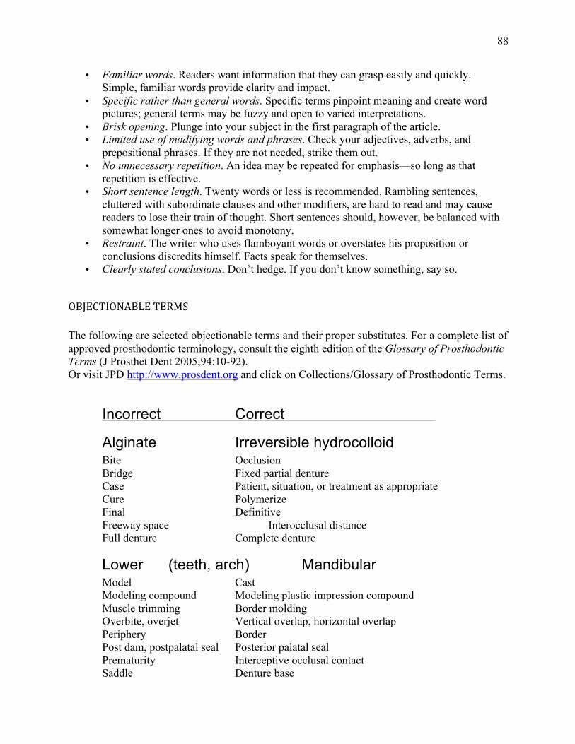
88
• Familiar words. Readers want information that they can grasp easily and quickly. Simple, familiar words provide clarity and impact.
• Specific rather than general words. Specific terms pinpoint meaning and create word pictures; general terms may be fuzzy and open to varied interpretations.
• Brisk opening. Plunge into your subject in the first paragraph of the article. • Limited use of modifying words and phrases. Check your adjectives, adverbs, and
prepositional phrases. If they are not needed, strike them out. • No unnecessary repetition. An idea may be repeated for emphasis—so long as that
repetition is effective. • Short sentence length. Twenty words or less is recommended. Rambling sentences,
cluttered with subordinate clauses and other modifiers, are hard to read and may cause readers to lose their train of thought. Short sentences should, however, be balanced with somewhat longer ones to avoid monotony.
• Restraint. The writer who uses flamboyant words or overstates his proposition or conclusions discredits himself. Facts speak for themselves.
• Clearly stated conclusions. Don’t hedge. If you don’t know something, say so.
OBJECTIONABLE TERMS The following are selected objectionable terms and their proper substitutes. For a complete list of approved prosthodontic terminology, consult the eighth edition of the Glossary of Prosthodontic Terms (J Prosthet Dent 2005;94:10-92). Or visit JPD http://www.prosdent.org and click on Collections/Glossary of Prosthodontic Terms.
Incorrect Correct
Alginate Irreversible hydrocolloid Bite Occlusion Bridge Fixed partial denture Case Patient, situation, or treatment as appropriate Cure Polymerize Final Definitive Freeway space Interocclusal distance Full denture Complete denture
Lower (teeth, arch) Mandibular Model Cast Modeling compound Modeling plastic impression compound Muscle trimming Border molding Overbite, overjet Vertical overlap, horizontal overlap Periphery Border Post dam, postpalatal seal Posterior palatal seal Prematurity Interceptive occlusal contact Saddle Denture base

89
Study model Diagnostic cast Upper (teeth, arch) Maxillary X-ray, roentgenogram Radiograph
IN ADDITION, SAMPLE IS OFTEN USED WHEN SPECIMEN IS MEANT.
Acrylic An adjective form that requires a noun, as in acrylic resin.
Affect, effect Affect is a verb; effect is a noun.
African American Spelled thus and preferred over Negro and black in both adjective (African American patients) and noun (. . . of whom 20% were African Americans) forms.
Ampersand Should be avoided except in the name of a firm, as in John Smith & Co.
Average, mean, median Mean and average are synonyms. Median refers to the midpoint in a range of items; the midpoint has many items above as below it.
Basic Like fundamental, this word is often unnecessary. An example of unnecessary use: Dental implants consist of two basic types: subperiosteal and endosteal.
Between, among Use between when 2 things are involved and among when there are more than 2.
Biopsy This noun should NOT be used as a verb. A biopsy was performed on the Tissue, rather than: The tissue was biopsied.
Centric An adjective that requires a noun, as in centric relation.
Currently, now, at present, etc. These expressions are often unnecessary, as in: This technique is currently being used… Data Use as a plural, as in: The data were…
Employ Should not become an elegant variation of use, as in This method is employed . . .
Ensure Preferred over insure in the sense of to make certain.
Fad words This group includes the "ize" family (conceptualize, prioritize, surgerize, finalize, etc.) and such terms as interpersonal, interrelationships, input, and viable. Several of these "words” have no dictionary standing at all (even those that do should be used with caution).
Fewer, less Use fewer with nouns that can be counted (fewer patients were seen) and less with nouns that cannot be counted (less material was used).
Following After is preferred.
Imply, infer
Additional Terminology Guidelines

90
The speaker implies; the listener infers.
Incidence The rate at which a disease occurs in a given time period; sometimes confused with prevalence (the total number of cases of a disease in a given region).
Majority Means more than half; use most when you mean almost all.
Male, female For adult humans, use men and women. For children, use boys and girls.
Must, should Must means that the course of action is essential. Should is less strong and means that the course of action is recommended.
Numbers
Spell out numbers used in titles or headings and numbers at the beginning of a sentence. The spelled version may also be preferable in a series of consecutive numbers that may confuse the reader (eg, 2 3.5-‐inch disks should be written two 3.5-‐inch disks). In all other cases, use Arabic numerals.
Orient Proper form; avoid orientate.
Paper (as in manuscript)
Use article.
Pathologic Use instead of pathological. Other words in which the suffix -al has been dropped include biologic, histologic, and physiologic.
Pathology The study of disease; often mistaken for pathosis (the condition of disease)
Percent Use the percent sign in the text, as in The distribution of scores was as follows: adequate, 8%; oversized, 23%; and undersized, 69%. But spell out when the percent opens a sentence, as in Twenty percent of the castings . . . Prior to Before is preferred. Rare, infrequent, often not, etc. Whenever possible, these vague terms should be backed up with a specific number.
Rather
Like very, this word should be avoided.
Regimen A planned program for taking medication, dieting, exercising, etc. Not to be confused with regime, meaning a system of government or management.
Symptomatology The science or study of symptoms; this word is not a synonym for the word symptoms.
Technique Preferred over technic.
Utilize Use is preferred.
Vertical An adjective that needs a noun, as in vertical relation.
Via Use through, with, or by means of. White Preferred over Caucasian. This is true only if the patient is from the Caucasus region of Eastern Europe. If not, use the term, white to describe the pati