Embed Size (px)
Citation preview

Universidade de Aveiro
2008
Departamento de Electrónica, Telecomunicações e Informática
Ricardo Jorge Magalhães de Matos
Suporte de Mobilidade em Redes WiMAX

Universidade de Aveiro
2008
Departamento de Electrónica, Telecomunicações e Informática
Ricardo Jorge Magalhães de Matos
Suporte de Mobilidade em Redes WiMAX
Dissertação apresentada à Universidade de Aveiro para cumprimento dos requisitos necessários à obtenção do grau de Mestre em Engenharia Electrónica e de Telecomunicações (Mestrado Integrado), realizada sob a orientação científica da Professora Dra. Susana Sargento, Professoraauxiliar convidada do Departamento de Electrónica, Telecomunicações e Informática da Universidade de Aveiro, e do Professor Francisco Fontes, Professor auxiliar convidado do Departamento de Electrónica, Telecomunicações e Informática da Universidade de Aveiro.


o júri
presidente Prof. Dr. Nuno Borges
Professor Associado do Departamento de Electrónica, Telecomunicações e Informática da Universidade de Aveiro
orientador Prof. Dra. Susana Sargento
Professora auxiliar convidada do Departamento de Electrónica, Telecomunicações e Informática da Universidade de Aveiro
co-orientador Prof. Dr. Francisco Fontes
Professor auxiliar convidado do Departamento de Electrónica, Telecomunicações e Informática da Universidade de Aveiro
arguente Prof. Dra. Marília Curado
Professora auxiliar do Departamento de Informática da Universidade de Coimbra


agradecimentos
Este trabalho assinala o fim de mais uma etapa da minha vida académica, mas não o teria conseguido concluir sem a contribuição de algumas pessoas. Por isso, não queria deixar de expressar aqui os meus mais sinceros agradecimentos a todos os que, directa ou indirectamente, contribuíram para a realização desta dissertação de mestrado.
Aos meus orientadores Prof. Dra. Susana Sargento e Prof. Francisco Fontes, pela disponibilidade, apoio e motivação dada ao longo destes meses na realização desta tese.
Ao meu colaborador Pedro Neves, por ter partilhado comigo todos os seus conhecimentos, revelando-se fundamental para a correcta abordagem dos diferentes desafios que me foram sucessivamente propostos.
Ao Instituto de Telecomunicações de Aveiro e aos seus colaboradores (principalmente João Monteiro e Telmo Pereira) por me terem oferecido todo o apoio e condições necessárias para o correcto desenvolvimento do meu trabalho.
Aos meus Pais e Irmão pelo incansável apoio, paciência e motivação que sempre me deram durante o desenvolvimento desta dissertação.


palavras-chave
IEEE 802.16, IEEE 802.21, WiMAX, Mobilidade, Qualidade de serviço, VoIP, IPTV, MIHF, handovers entre redes heterogéneas.
resumo
O desenvolvimento crescente da Internet, com novos serviços e aplicações que requerem elevadas exigências a nível de qualidade de serviço, como por exemplo, o VoIP e IPTV, a crescente necessidade de um utilizador estar sempre contactável em qualquer sítio e a qualquer momento, torna necessária a integração actual da Internet com as redes móveis da próxima geração.
A tecnologia IEEE 802.16 surge como uma tecnologia de banda larga sem fios que pode ter um papel fundamental num ambiente de próxima geração. Devido aos seus baixos custos de instalação e à possibilidade de chegar facilmente a zonas rurais ou a zonas de difícil acesso, torna-se um sério candidato para suprir as necessidades dos utilizadores.
A necessidade de mobilidade pelo utilizador, para aceder a diversos serviços em diferentes sítios ou ser identificado remotamente para a posterior recepção de informação também é um desejo futuro.
O protocolo IEEE 802.21 surge como um meio que providencia a optimização de handover entre diferentes tecnologias de acesso, quer sejam elas WiFi, WiMAX, 3GGP ou 3GPP2, no sentido de proporcionar ao utilizador a utilização de diferentes serviços de uma forma transparente à tecnologia de acesso, quando em situações de mobilidade.
Esta dissertação apresenta a arquitectura desenvolvida para proporcionar a correcta avaliação da atribuição de QoS e mobilidade transparente, num ambiente real de próxima geração. Serão também efectuados testes com o equipamento WiMAX disponível, no sentido de mostrar o seu correcto comportamento na atribuição de QoS fim-a-fim em cenários ponto-a-ponto e ponto-a-multiponto com serviços com características de tempo real. A integração do software da primeira fase do projecto WEIRD e o seu correcto comportamento em ambientes de atribuição de QoS também vai ser estudado. A implementação dos diferentes módulos, em especial a implementação da unidade central da arquitectura de IEEE 802.21 (MIHF), vai ser descrita, no sentido de avaliar o desempenho do WiMAX e do protocolo IEEE 802.21 numa rede real no âmbito da segunda fase do projecto WEIRD. Os resultados obtidos demonstram que a arquitectura desenvolvida consegue fornecer QoS fim-a-fim com suporte de mobilidade entre redes heterogéneas.


keywords
IEEE 802.16, IEEE 802.21, WiMAX, Mobility, Quality of Service, VoIP, IPTV, MIHF, handovers between heterogeneous networks.
abstract
The growing development of the Internet, with new services and applications that require a high level of quality of service, such as, VoIP and IPTV, the increasing need for a user to be always reachable anywhere and at anytime, motivates the integration of current Internet with the next generation of mobile networks.
The IEEE 802.16 technology emerges as a technology for broadband wireless access that may have a key role in a next generation environment. Due to its low costs of installation and its ability to easily reach rural areas or areas with difficult access, it becomes a serious candidate to supply the needs of users.
The mobility’s necessity by the user, to access to several services in different locations or be identified remotely for subsequent receipt of information, is also a future desire.
The IEEE 802.21 protocol provides the optimization of handover between heterogeneous networks, such as WiFi, WiMAX, 3GGP or 3GPP2, to offer the user different services in a transparent manner to his access technology, when in situations of mobility.
This Thesis presents the architecture developed to provide the correct integration of QoS and seamless mobility, in a real next generation environment. It will also present tests carries out with the available WiMAX equipment, to show its correct behaviour in the allocation of end-to-end QoS in point-to-point and point-to-multipoint scenarios with real-time services. The integration of software from the first phase of the WEIRD project and its correct behaviour in environments of QoS allocation will also be studied. The implementation of the various modules, in particular the implementation of the central unit of IEEE 802.21 architecture (MIHF), will be described, to evaluate the performance of WiMAX and IEEE 802.21 protocol in a real networkprovided by the second phase of the WEIRD project. The obtained results show that the developed architecture is able to provide end-to-end QoS with seamless mobility support over heterogeneous networks.


- i -
Table of ContentsTable of ContentsTable of ContentsTable of Contents
Index of Figures ................................................................................................................... iv Index of Tables....................................................................................................................vii Acronyms............................................................................................................................. ix 1. Introduction...................................................................................................................... 1
1.1. Motivation.................................................................................................................. 1 1.2. Objectives................................................................................................................... 3 1.3. Contributions of the Thesis....................................................................................... 4 1.4. Organization of the Thesis ........................................................................................ 4
2. Background ....................................................................................................................... 6 2.1. Broadband Wireless Access ...................................................................................... 6
2.1.1. IEEE 802.16......................................................................................................... 7 2.1.1.1. IEEE 802.16-2004 MAC Layer........................................................................ 7 2.1.1.2. IEEE 802.16-2004 PHY Layer....................................................................... 10 2.1.1.3. IEEE 802.16e-2005 ........................................................................................ 11 2.1.2. IEEE 802.16 Hardware – Redline Communications AN-100U ..................... 11
2.2. Mobility.................................................................................................................... 13 2.2.1. Mobility Concepts ............................................................................................ 13 2.2.2. IEEE 802.21....................................................................................................... 16 2.2.2.1. Main Goals ..................................................................................................... 16 2.2.2.2. IEEE 802.21 Architecture ............................................................................. 17
2.3. Summary .................................................................................................................. 21 3. IEEE 802.16 for Real-time Services: IPTV and VoIP ................................................... 23
3.1. Testbeds and Methodologies................................................................................... 23 3.1.1. Testbed .............................................................................................................. 23 3.1.2. Methodology..................................................................................................... 24 3.1.3. Conduct and Experiment ................................................................................. 26
3.2. VoIP and IPTV over WiMAX without QoS .......................................................... 27 3.2.1. Results ............................................................................................................... 28 3.2.1.1. Measurements................................................................................................ 28 3.2.2. Conclusions....................................................................................................... 32
3.3. VoIP and IPTV over WiMAX with QoS................................................................ 32 3.3.1. No Background traffic ...................................................................................... 33 3.3.1.1. Results ............................................................................................................ 33 3.3.1.1.1. Measurements............................................................................................. 33 3.3.1.2. Conclusions.................................................................................................... 37 3.3.2. Background Traffic in Best Effort.................................................................... 37 3.3.2.1. Results ............................................................................................................ 38 3.3.2.1.1. Measurements............................................................................................. 38 3.3.2.2. Conclusions.................................................................................................... 41
- ii -
3.4. VoIP Aggregation over WiMAX ............................................................................ 41 3.4.1. Testbed and Methodology................................................................................ 41 3.4.1.1. Testbed ........................................................................................................... 41 3.4.1.2. Methodology.................................................................................................. 42 3.4.2. Results ............................................................................................................... 44 3.4.2.1. Measurements................................................................................................ 44 3.4.3. Conclusions....................................................................................................... 50
3.5. Summary .................................................................................................................. 51 4. WEIRD Architecture – Overview and Results............................................................. 52
4.1. High Level View of WEIRD architecture.............................................................. 52 4.1.1. Control Plane.................................................................................................... 54
4.2. Legacy Scenarios Implemented .............................................................................. 55 4.2.1. Inter Module Signalling ....................................................................................... 56 4.3. Performed tests ........................................................................................................ 59
4.3.1. Processing times for signalling ........................................................................ 59 4.3.1.1. Point-to-Point Scenario ................................................................................ 59 4.3.1.2. Point-to-Multipoint Scenario ....................................................................... 62 4.3.2. QoS Tests........................................................................................................... 63
4.4. Summary .................................................................................................................. 66 5. Mobility Architecture and Development...................................................................... 67
5.1. WEIRD architecture with mobility ....................................................................... 67 5.1.1. Objectives.......................................................................................................... 67 5.1.2. Overwiew.......................................................................................................... 67
5.2. Mobility Modules .................................................................................................... 68 5.2.1. Lower Layer Controller.................................................................................... 68 5.2.2. NSIS Mobility NSLP ......................................................................................... 70 5.2.3. Mobility GUI .................................................................................................... 70 5.2.4. CSC_MS............................................................................................................. 71 5.2.5. CSC_ASN .......................................................................................................... 74 5.2.6. MIHF................................................................................................................. 75 5.2.7. Interaction ........................................................................................................ 75
5.3. MIHF Implementation ............................................................................................ 78 5.3.1. Configuration and Topology............................................................................ 79 5.3.2. MIHF Engine .................................................................................................... 81 5.3.3. L2 Message Process........................................................................................... 81 5.3.4. MIHU and NSIS Message Process.................................................................... 82
5.4. Messages exchanged between Mobility Modules .................................................. 83 5.4.1. MIH_LINK_SAP Interface............................................................................... 84 5.4.1.1. MIH_LINK_SAP Header............................................................................... 84 5.4.1.2. MIH_LINK_SAP Primitives.......................................................................... 84 5.4.2. MIH_NET_SAP Interface ................................................................................ 85 5.4.2.1. MIH_NET_SAP Header ................................................................................ 86

- iii -
5.4.2.2. MIH_NET_SAP Primitives ........................................................................... 87 5.4.3. MIH_SAP Interface.......................................................................................... 90 5.4.3.1. MIH_SAP Header.......................................................................................... 90 5.4.3.2. MIH_SAP Primitives..................................................................................... 90
5.5. Summary .................................................................................................................. 92 6. Mobility: Real Experimental Scenarios and Results ..................................................... 94
6.1. Mobility Scenario .................................................................................................... 94 6.1.1. Inter module signalling .................................................................................... 96 6.1.2. Performed tests ................................................................................................. 98 6.1.2.1. Processing times for resource allocation ...................................................... 98 6.1.2.1.1. Results ......................................................................................................... 99 6.1.2.2. Processing times for MIHF ......................................................................... 102
6.2. Mobility Advanced Scenario................................................................................. 104 6.3. Summary ................................................................................................................ 105
7. Conclusion .................................................................................................................... 106 7.1. Final Conclusion.................................................................................................... 106 7.2. Future work ........................................................................................................... 107
8. References..................................................................................................................... 108 9. Annex 1 – WEIRD phase 1 software installation and configuration ........................ 112
9.1. Developed Architecture ........................................................................................ 112 9.2. MS........................................................................................................................... 112 9.3. CSN......................................................................................................................... 113 9.4. ASN......................................................................................................................... 114 9.5. Important information .......................................................................................... 116
10. Annex 2 – WEIRD phase 2 software installation and configuration ...................... 117 10.1. Developed architecture ....................................................................................... 117 10.2. MS......................................................................................................................... 117 10.3. CSN....................................................................................................................... 120 10.4. ASN....................................................................................................................... 121 10.5. AP ......................................................................................................................... 124 10.6. Important information ........................................................................................ 125
11. Annex 3 – MIHF Implementation............................................................................. 126 11.1. Messages sent by LLC.......................................................................................... 126 11.2. NSIS Mobility NSLP ............................................................................................ 128 11.3. MIHF Primitives.................................................................................................. 129
11.3.1. MIHF_LINK_SAP Interface......................................................................... 129 11.3.2. MIHF_NET_SAP Interface .......................................................................... 130 11.3.3. MIH_SAP Interface...................................................................................... 135

- iv -
Index of FiguresIndex of FiguresIndex of FiguresIndex of Figures
Figure 1 - WiMAX applications for near future ................................................................... 2 Figure 2 - Main function of IEEE 802.21 protocol ............................................................... 2 Figure 3 - IEEE 802.16 – 2004 layers (MAC and PHY)...................................................... 7 Figure 4 - Classification and CID Mapping......................................................................... 8 Figure 5 - MIPv4 main elements ....................................................................................... 15 Figure 6 - MIHF reference model...................................................................................... 18 Figure 7 - Remote MIH Event ........................................................................................... 18 Figure 8 - Remote MIH Command.................................................................................... 19 Figure 9 - MIHF interfaces................................................................................................. 21 Figure 10 - Communication between different MIHFs ................................................... 21 Figure 11 - Schematic of our WiMAX testbed ................................................................. 24 Figure 12 - Measured Packet Loss ..................................................................................... 29 Figure 13 - Measured Jitter ................................................................................................ 30 Figure 14 - Measured Goodput .......................................................................................... 31 Figure 15 - Measured One Way Delay.............................................................................. 32 Figure 16 - Measured Packet Loss ..................................................................................... 34 Figure 17 - Measured Jitter ................................................................................................ 35 Figure 18 - Measured Goodput .......................................................................................... 36 Figure 19 - Measured One Way Delay.............................................................................. 37 Figure 20 - New schematic of our WiMAX testbed ......................................................... 38 Figure 21 - Measured Packet Loss ..................................................................................... 39 Figure 22 - Measured Jitter at SS1 for VoIP with BE ....................................................... 40 Figure 23 - Measured Goodput at SS1 for VoIP with BE ................................................. 40 Figure 24 - Measured One Way Delay at SS1 for VoIP with BE..................................... 41 Figure 25 - Schematic of our WiMAX testbed ................................................................. 42 Figure 26 - G.723.1 sample application-layer aggregation............................................... 43 Figure 27 - Cumulative downlink Goodput...................................................................... 45 Figure 28 - Cumulative uplink Goodput ........................................................................... 45 Figure 29 - Average downlink Packet Loss....................................................................... 46 Figure 30 - Average uplink Packet Loss ............................................................................ 47 Figure 31 - Average downlink Sample Loss...................................................................... 48 Figure 32 - Average uplink Sample Loss ........................................................................... 48 Figure 33 - Downlink Mean Opinion Score ..................................................................... 50 Figure 34 - Uplink Mean Opinion Score........................................................................... 50 Figure 35 - General architectural planes in a multi-domain environment [4]..................... 53 Figure 36 - WEIRD’s Phase 1 Architecture – Control Plane........................................... 54 Figure 37 - Point-to-Point Scenario .................................................................................. 56 Figure 38 - Point-to-Multipoint Scenario......................................................................... 56

- v -
Figure 39 - PTP Inter-module Signalling.......................................................................... 57 Figure 40 - PMP Inter-module Signalling......................................................................... 58 Figure 41 - Percentage of Successful Requests.................................................................. 60 Figure 42 - Processing time by NSIS (MS<->ASN) ........................................................... 60 Figure 43 - Diameter Signalling......................................................................................... 61 Figure 44 - Processing time between CSC_ASN and the Equipment.............................. 61 Figure 45 - Processing time by CSCs................................................................................. 62 Figure 46 - End- to-End time............................................................................................. 62 Figure 47 - End- to-End time............................................................................................. 63 Figure 48 - Cumulative uplink Goodput ........................................................................... 64 Figure 49 - Average uplink Packet Loss ............................................................................ 64 Figure 50 - Uplink Mean Opinion Score........................................................................... 65 Figure 51 - Cumulative downlink Goodput...................................................................... 65 Figure 52 - Average downlink Packet Loss....................................................................... 66 Figure 53 - Downlink Mean Opinion Score ..................................................................... 66 Figure 54 - WEIRD’s Phase 2 Architecture – Control Plane........................................... 68 Figure 55 - LLC Graphical User Interface......................................................................... 69 Figure 56 - MIH NSLP architecture .................................................................................. 70 Figure 57 - Mobility GUI ................................................................................................... 70 Figure 58 - CSC_MS architecture ...................................................................................... 72 Figure 59 - CSC_MS Mobility Manager architecture....................................................... 72 Figure 60 - MIHF Attendant architecture ........................................................................ 74 Figure 61 - CSC_ASN architecture.................................................................................... 74 Figure 62 - Relationship between different MIHF SAPs ................................................. 75 Figure 63 - MIHU Register ................................................................................................ 76 Figure 64 - MIHU Event Subscribe ................................................................................... 76 Figure 65 - Link_Up Event processing .............................................................................. 77 Figure 66 - Link_Going_Down Event processing............................................................. 77 Figure 67 - Link_Down Event processing......................................................................... 78 Figure 68 - MIHF intelligence ........................................................................................... 79 Figure 69 - Receiving LLA Event ...................................................................................... 81 Figure 70 - Receiving MIHU Register............................................................................... 82 Figure 71 - Receiving MIHU Event Subscribe.................................................................. 82 Figure 72 - Receiving MIHU Link Action ........................................................................ 83 Figure 73 - MIH_LINK_SAP Frame Format..................................................................... 84 Figure 74 - MIH_LINK_SAP Header Structure................................................................ 84 Figure 75 - MIH_NET_SAP Frame Format ...................................................................... 86 Figure 76 - MIH Protocol Header Structure..................................................................... 86 Figure 77 - Mobility Scenario ............................................................................................ 95 Figure 78 - State 1 – QoS Reservation............................................................................... 96 Figure 79 - State 2 – Handover Preparation ..................................................................... 97 Figure 80 - State 3 – Handover Process............................................................................ 98

- vi -
Figure 81 - Processing time between CSC_ASN and the Equipment............................ 100 Figure 82 - Diameter Signalling....................................................................................... 100 Figure 83 - Processing time by NSIS ............................................................................... 101 Figure 84 - Processing time by CSC´s............................................................................. 101 Figure 85 - End- to-End time........................................................................................... 102 Figure 86 - MIHF processing times at different situations............................................. 103 Figure 87 - Time left in the MIHF<->CSC communication........................................... 103 Figure 88 - Time left in the MIHF<->MIHF communication........................................ 104 Figure 89 - Mobility Advanced Scenario ........................................................................ 104 Figure 90 - NSIS usage to transport MIH Messages........................................................ 128 Figure 91 - Message transport between two MIH NSLP................................................ 128

- vii -
Index of TablesIndex of TablesIndex of TablesIndex of Tables
Table 1 - Link Events ......................................................................................................... 18 Table 2 - MIH Events ......................................................................................................... 19 Table 3 - Link Commands.................................................................................................. 19 Table 4 - MIH Commands.................................................................................................. 20 Table 5 - Service Management primitives ........................................................................ 20 Table 6 - Testbed Configuration........................................................................................ 24 Table 7 - Network Interfaces Information handled by the node manager ..................... 72 Table 8 - MIHF struct......................................................................................................... 79 Table 9 - MIHU struct ........................................................................................................ 80 Table 10 - Physical Layer struct ........................................................................................ 80 Table 11 - MIHF and MIHU services struct ..................................................................... 80 Table 12 - Description of MIH_LINK_SAP Header fields ............................................... 84 Table 13 - MIH_LINK_SAP primitives ............................................................................. 85 Table 14 - MIH Protocol Header fields ............................................................................. 87 Table 15 - MIH_NET_SAP primitives............................................................................... 88 Table 16 - MIH_SAP primitives ........................................................................................ 91 Table 17 - WEIRD modules involved ............................................................................... 95 Table 18 - LLC Link_Up message .................................................................................... 126 Table 19 - LLC Link_Down message............................................................................... 127 Table 20 - LLC Link_Going_Down message................................................................... 127 Table 21 - Link_Up.indication primitive parameters..................................................... 129 Table 22 - Link_Down.indication primitive parameter................................................. 129 Table 23 - Link_Going_Down.indication primitive parameters ................................... 130 Table 24 - Link_Action.request primitive parameters ................................................... 130 Table 25 - MIH_Register.request primitive parameters................................................. 131 Table 26 - MIH_Register.response primitive parameters .............................................. 131 Table 27 - MIH_Event_Subscribe.request primitive parameters .................................. 131 Table 28 - MIH_Event_Subscribe.response primitive parameters ................................ 132 Table 29 - MIH_Link_Up.indication primitive parameters........................................... 132 Table 30 - MIH_Link_Down.indication primitive parameters ..................................... 133 Table 31 - MIH_Link_Going_Down.indication primitive parameters ........................ 133 Table 32 - MIH_Get_Information.request primitive parameters.................................. 134 Table 33 - MIH_Get_Information.response primitive parameters................................ 135 Table 34 - MIH_Link_Action.request primitive parameters ......................................... 135 Table 35 - MIH_Register.request primitive parameters................................................. 135 Table 36 - MIH_Register.confirm primitive parameters ............................................... 136 Table 37 - MIH_Event_Subscribe.request primitive parameters .................................. 136 Table 38 - MIH_Event_Subscribe.confirm primitive parameters ................................. 136 Table 39 - MIH_Link_Up.indication primitive parameters........................................... 137

- viii -
Table 40 - MIH_Link_Down.indication primitive parameters ..................................... 137 Table 41 - MIH_Link_Going_Down.indication primitive parameters ......................... 138 Table 42 - MIH_Get_Information.request primitive parameters.................................. 138 Table 43 - MIH_Get_Information.confirm primitive parameters................................. 139 Table 44 - MIH_Link_Action.request primitive parameters ......................................... 139
- ix -
AcronymsAcronymsAcronymsAcronyms
Acronym Description
3GPP Third Generation Partnership Project 3GPP2 Third Generation Partnership Project 2 A ASN Access Service Network ASN-GW Access Service Network - Gateway ACK Acknowledge AID Action Identifier AC Admission Control AVC Advanced Video Coding API Application Program Interface ADSL Asymmetric Digital Subscriber Line ATM Asynchronous Transfer Mode AAA Authentication, Authorization and Accounting B BS Base Station BE Best Effort BWA Broadband Wireless Access C CoA Care of Address CPS Common Part Sublayer CID Connection Identifier CSC Connectivity Service Controller CSN Connectivity Service Network CBR Constant Bit Rate CPl Control Plane CS Convergence Sublayer CN Correspondent Node CPE Customer Premises Equipment D DB Database DPl Data Plane DSL Digital Subscriber Line E ETH Ethernet ertPS extended real-time Polling Service F FBSS Fast Base Station Switching FCAPS Fault, Configuration, Accounting, Performance, Security
management FTP File Transfer Protocol FIFO First In First Out FA Foreign Agent

- x -
FDD Frequency Division Duplexing FDM Frequency Division Multiplexing G GIST General Internet Signaling Protocol GPS Global Positioning System GUI Graphical User Interface H HO Handoff/Handover HTTP Hypertext Transfer Protocol HA Home Agent HIP Host Identity Protocol I ID Identifier IETF Internet Engineering Task Force IP Internet Protocol IPTV Internet Protocol Television IPv4 Internet Protocol version 4 IPv6 Internet Protocol version 6 IEEE Institute of Electrical and Electronics Engineers J JTG Jugi’s Traffic Generator K L L2 Layer 2 L3 Layer 3 LOS Line of Sight LLA Lower Level Agent LLC Lower Layer Controller M MDHO Macro Diversity Handover MPl Management Plane MTU Maximum Transfer Unit MOS Mean Opinion Score MICS Media Independent Command Service MIES Media Independent Event Service MIIS Media Independent Information Service MIH Media Independent Handover MIHF Media Independent Handover Function MIHU Media Independent Handover User MAC Medium Access Control MAN Metropolitan-Area Networks MAHO Mobile Assisted Handover MCHO Mobile Controlled Handover MIHO Mobile Initiated Handover MIP Mobile IP MIPv4 Mobile IP version 4

- xi -
MIPv6 Mobile IP version 6 MN Mobile Node MS Mobile Station MT Mobile Terminal MM Mobility Manager MPEG Moving Picture Experts Group MIMO Multiple Input Multiple Output N NCHO Network Controlled Handover NIHO Network Initiated Handover NSIS Next Step In Signaling NSLP NSIS Signaling Layer Protocol NLOS Non Line of Sight nrtPS non-real-time Polling Services O OPCODE Operation Code OFDM Orthogonal Frequency Division Multiple OFDMA Orthogonal Frequency Division Multiple Access P PC Personal Computer PHY Physical PHP Hypertext Preprocessor PoA Point of Attachment PTP Point-to-Point PMP Point-to-Multipoint PTPd Precision Time Protocol daemon PDU Protocol Data Unit PSTN Public Switched Telephone Network Q QoS Quality of Service QoSNSLP Quality of Service NSIS Signaling Layer Protocol R rtPS real-time Polling Services RTPS Real Time Streaming Protocol RTP Real Time Transport Protocol Rx Reception RC Resource Controller RM Resource Manager S SAP Service Access Point SDU Service Data Unit SF Service Flow SID Service Identifier SIP Session Initiation Protocol SID Silence Insertion Descriptor SNMP Simple Network Management Protocol

- xii -
SS Subscriber Station T TV Television TDD Time Division Duplexing Tx Transmission TCP Transmission Control Protocol TLV Type Length Value ToS Type of Service U URL Uniform Resource Locator UGS Unsolicited Grant Services UDP User Datagram Protocol V VBR Variable Bit Rate VLC Video Lan Client VLAN Virtual Local Area Network VoIP Voice over IP W WA Weird Agent WLAN Wireless Local Area Network Wi-Fi Wireless Fidelity, refers to 802.11 standards, including
802.11b, 802.11a, and 802.11g WiMAX Worldwide Interoperability for Microwave Access WEIRD WiMAX Extension to Isolated Research Data networks X Y Z

Ricardo MatoRicardo MatoRicardo MatoRicardo Matossss 1
1.1.1.1.IntroductionIntroductionIntroductionIntroduction
1.1.1.1.1.1.1.1.MotivationMotivationMotivationMotivation
One area of research in telecommunications, with increasing interest, relates to the next generation of mobile communications systems. These systems, with support for multiple - technologies without wires, will provide high bandwidth and transparent communication capabilities to the user.
The growing need of users to be ‘linked’ at anytime and anywhere has led to the integration of the Internet with the mobile networks. However, there are always areas of difficult access where Internet access is difficult to achieve [10].
The rapid growth of high-speed Internet generated a huge demand in the residential and business markets. Despite a large percentage of that connectivity is provided by Asymmetric Digital Subscriber Line (ADSL) system, the future is not in ADSL, as the cable connection is not available in all areas [43].
The ability to have a Broadband Wireless Access (BWA) to Internet anywhere and at anytime has become a near dream for most users and mobile devices. The technology for metropolitan access IEEE 802.16 (commonly called Worldwide Interoperability for Microwave Access - WiMAX) is a technology for BWA with low cost compared to solutions of fibre, cable or copper, which is a very important factor in developing countries or rural areas [10].
The IEEE 802.16 group provides support for mobile access, by defining the IEEE 802.16e standard, placing mobility in this scenario of metropolitan networks. Thus, this technology becomes very promising for use in environments of next generation. In environments of next generation networks, users want access to all possible services, including multimedia in its various topological aspects (point-to-point (PTP), point-to-multipoint (PMP), mesh), and operators need to support their requirements: support new services in real time with high quality, independent of the users mobility.
The IEEE 802.16 will soon become one of the most powerful wireless technologies in the market. It is a standards-based technology provides fixed and mobile wireless broadband connectivity with a lot of possible applications as shown in Figure 1.

Ricardo MatoRicardo MatoRicardo MatoRicardo Matossss 2
Figure Figure Figure Figure 1111 ---- WiMAX applications for near future
Another open issue in the near future is the seamless handover (HO) procedure in the next generation of networks. For mobile users, handovers may occur due to changes in wireless link conditions. For the stationary user, handovers may become imminent when the surrounding network environment changes, making one network more attractive than another. Another possibility is that the user may choose an application which may require a higher data rate channel, for example during download of a large data file. In all such cases service continuity should be maintained to the extent possible during handover. As an example, when making a network transition during a phone call, the handover procedures should be executed in such a way that any perceptible interruption to the conversation will be minimized [3].
The IEEE 802.21 (Media Independent Handover Services) standard provides link layer intelligence and other related network information to upper layers to optimize handovers between heterogeneous networks, as we can see in Figure 2. It provides the definition of algorithms to facilitate seamless handover between networks of the same (HO Horizontal) or of different technologies (HO Vertical) [3].
Figure Figure Figure Figure 2222 ---- Main function of IEEE 802.21 protocol

Ricardo MatoRicardo MatoRicardo MatoRicardo Matossss 3
In the one hand, IEEE 802.16 helps on the process of ubiquitous Internet access allowing users to be connected to the Internet in remote locations. In other hand, users require seamless handover maintaining its Quality of Service (QoS) requirements.
In order to successful integrate these two point of views, which are indeed important to the near future, WEIRD (WiMAX Extension to Isolated Research Data networks) project [4][5] aims to develop the QoS and mobility aspects of the IEEE 802.16 technology integrating IEEE 802.21 protocol.
WEIRD is an European IST project which aims to demonstrate the effectiveness of IEEE 802.16 equipment in real-scenarios such as fire prevention, telemedicine, video surveillance, real time services such IPTV (Internet Protocol Television) and VoIP (Voice over IP), and mobility questions [30][32][33]. For this purpose, it was defined an end-to-end QoS architecture with mobility support and real time services support in a heterogeneous environment.
1.2.1.2.1.2.1.2.ObjectivesObjectivesObjectivesObjectives
This Thesis aims to assist in the integration of the IEEE 802.16 network technology in a heterogeneous network with support for mobility. This work requires a familiarity with technology and testing of IEEE 802.16 equipment.
It also studies the mechanisms to support mobility in the IEEE 802.16 technology and in its integration with heterogeneous environments, implementing Media Independent Handover Function (MIHF) and integrating them with IEEE 802.16 and mobility schemes.
For the development of mobility mechanisms, the architecture will use the concepts of local and global mobility, and concepts of independent technology mobility (Media Independent Handovers, IEEE 802.21) applied to 802.16e networks with intrinsic mobility.
The following activities will be developed:
• Study of BWA Technologies, giving special emphasis on IEEE 802.16d and IEEE 802.16e.
• Revision of QoS support (in PTP and PMP scenarios).
• Learning of technology IEEE 802.16e features for mobility.
• Study of mechanisms for management the local and global mobility.
• Study of technology IEEE 802.21 for Media Independent Handover (MIH).

Ricardo MatoRicardo MatoRicardo MatoRicardo Matossss 4
• Carrying out tests of operation and performance with the 802.16 equipment available. This includes the evaluation of real-time services, such as VoIP and IPTV, over WiMAX which is able to provide end-to-end QoS. We will also evaluate several mechanisms of VoIP aggregation.
• Development of a mobility mechanism with support for QoS, which includes the implementation of the MIHF (the central unit of the IEEE 802.21 architecture).
• Realization of experiences with real equipment and evaluation of performance.
1.3.1.3.1.3.1.3.Contributions of the ThesisContributions of the ThesisContributions of the ThesisContributions of the Thesis
As result of the accomplishment of the majority part of the proposed objectives, this work provides the following set of contributions:
• The development of a MIHF module and its integration in a real testbed of the WEIRD European IST Project [4][5].
• The evaluation of real time services (VoIP and IPTV) over WiMAX, being valuable to the WiMAX development and its establishment in the next generation networks.
• The work developed in this Thesis, particularly the evaluation of the effectiveness of the WEIRD project in terms of resource allocation and QoS performance with real-time services, is the purpose of one chapter of a WiMAX book:
o Pedro Neves, Susana Sargento, Kostas Pentikousis, Ricardo Matos, Giada Landi, Marília Curado, Francisco Fontes, "A WiMAX Cross Layer Framework for Next Generation Networks", WiMAX Book, Wiley, accepted for publication, 2008.
1.4.1.4.1.4.1.4.OrganiOrganiOrganiOrganization of the Thesiszation of the Thesiszation of the Thesiszation of the Thesis
The present thesis is organized as follows:
• Chapter 2 provides an overview of the IEEE 802.16 standard, including the Medium Access Control (MAC) and Physical (PHY) layers. It will be made a short comparison between the fixed and mobile IEEE 802.16 standards, and the main characteristics of the equipment used for the thesis. At this chapter we will also depict the mobility mechanisms that exist, giving special emphasis on IEEE 802.21.

Ricardo MatoRicardo MatoRicardo MatoRicardo Matossss 5
• Chapter 3 provides some experiences with real time traffic (VoIP and IPTV) under the WiMAX equipment. We will evaluate the QoS performance of the equipment used.
• Chapter 4 provides a brief description of the WEIRD’s phase 1 architecture, as well as the network modules that have been defined. We will evaluate the effectiveness of the WEIRD’s phase 1 architecture in terms of its resource allocation capabilities.
• Chapter 5 describes the WEIRD’s phase 2 architecture, giving special emphasis on mobility requirements of the project. At this chapter it will be detailed the implementation of the MIHF, including its functions and functionalities.
• Chapter 6 discusses the measurement results obtained for the implemented module (MIHF) in a real mobility scenario provided by WEIRD’s phase 2 architecture and depicts a scenario for advanced mobility features.
• Chapter 7 presents the conclusions of this work, as well as the possible future work.

Ricardo MatoRicardo MatoRicardo MatoRicardo Matossss 6
2.2.2.2.BackgroundBackgroundBackgroundBackground
At this chapter will be explained all the background necessary to the Thesis. At Section 2.1 will be depicted the rise of the Broadband Wireless Access (BWA) technologies in which is included the IEEE 802.16 standard (commonly named Worldwide interoperability for Microwave Access - WiMAX), which will be described along this section, more specifically its Medium Access Control (MAC) and Physical (PHY) layers, the two modes of operation: fixed and mobile, and the WiMAX equipment used to perform real measurements. Section 2.2 provides the introduction of mobility mechanisms, giving special emphasis to IEEE 802.21 standard and its main goals to promote a seamless handover (HO) in a next-generation environment. Section 2.3 provides a brief summary of the chapter.
2.1.2.1.2.1.2.1.Broadband Wireless AccessBroadband Wireless AccessBroadband Wireless AccessBroadband Wireless Access
Broadband Wireless Access (BWA) is an emerging wireless technology that allows simultaneous wireless delivery of voice, data, and video. This technology provides an alternative solution for the last mile delivery of high-speed internet and other data services to business and homes. They are less expensive and more rapidly deployed than traditional optical fibre or wired telephone solutions. The goal of this new technology is to enable worldwide deployment of affordable, ubiquitous, always-on and interoperable multi-vendor mobile broadband wireless access networks that meet the needs of business and residential end user markets.
There are two different types of broadband wireless services, the fixed wireless broadband, which provides traditional fixed-line broadband services, and the mobile wireless broadband, which provides more features to the user such as the mobility, nomadicity and portability [7].
One of the most promising technology for BWA is the WiMAX [40], which offers both fixed and mobile access over the same infrastructure, opening the way for a new personal broadband service that gives users continuous broadband Internet access at home, at work, and while they are on the move. The WiMAX can be used on a variety of wireless broadband connections and solutions:
• "Last Mile" Broadband Access Solution to Metropolitan-Area Networks (MAN) connections to home and business office, specially in those areas that were not served by cable or DSL (Digital Subscriber Line) or in areas where the local telephone company may need a long time to deploy broadband service.
• Backhaul networks for cellular base stations, bypassing the Public Switched Telephone Network (PSTN); the cellular service providers can look to wireless backhaul as a more cost-effective alternative. The robust WiMAX technology

Ricardo MatoRicardo MatoRicardo MatoRicardo Matossss 7
makes it a nice choice for backhaul for enterprises such as hotspots as well as point-to-point backhaul solutions.
• Backhaul enterprise connections to the Internet for WiFi hotspots. It will allow users to connect to a wireless Internet service provider even when they roam outside their home or business office.
• A variety of new business services by wireless Internet service provider.
2.1.1.2.1.1.2.1.1.2.1.1.IEEE 802.16 IEEE 802.16 IEEE 802.16 IEEE 802.16
WiMAX technology is presently one of the most promising global telecommunication systems.
Great hopes and important investments have been made for WiMAX, which is a BWA system having many applications.
WiMAX is based on the IEEE 802.16 standard (802.16-2004 [1] for fixed and 802.16e-2005 [2] for mobile), having a rich set of features. These standards define the MAC and the PHY Layes of a fixed and mobile BWA System. The architecture of WiMAX System is defined by the WiMAX Forum [40].
More technically WiMAX is a layer 1 (PHY) and layer 2 (MAC) technology. It uses Orthogonal Frequency Division Multiple (OFDM) transmission and presents a sophisticated MAC Layer which provides efficient use of the frequency and Quality of Service (QoS) Management in order to obtain high data rates and different types of transmission services: voice, video, games, real-time, Best Effort … Two topologies (modes) can be used: PMP and Mesh.
2.1.1.1.2.1.1.1.2.1.1.1.2.1.1.1.IEEE 802.16IEEE 802.16IEEE 802.16IEEE 802.16----2004 MAC Layer2004 MAC Layer2004 MAC Layer2004 MAC Layer
Figure 3 describes the IEEE 802.16-2004 MAC and PHY layers.
Figure Figure Figure Figure 3333 ---- IEEE 802.16 IEEE 802.16 IEEE 802.16 IEEE 802.16 –––– 2004 layers (MAC and PHY) 2004 layers (MAC and PHY) 2004 layers (MAC and PHY) 2004 layers (MAC and PHY)
Ricardo MatoRicardo MatoRicardo MatoRicardo Matossss 8
The MAC Layer provides the interface with higher layers through the Service Specific Convergence Sublayer. Below the Service Specific Convergence Sublayer (CS) we find the Common Part Sublayer (CPS) that is the responsible for the most important MAC functions. Finally there is the Security Sublayer [1].
• Service Specific Convergence Sublayer
As the name implies, the convergence sublayer handles the convergence of different services supporting both ATM services and packet services, such as IPv4, IPv6, Ethernet, and VLAN services.
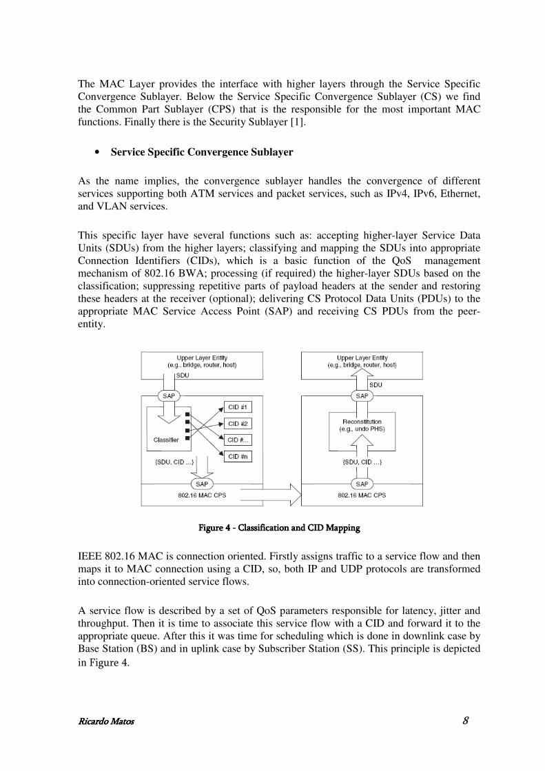
This specific layer have several functions such as: accepting higher-layer Service Data Units (SDUs) from the higher layers; classifying and mapping the SDUs into appropriate Connection Identifiers (CIDs), which is a basic function of the QoS management mechanism of 802.16 BWA; processing (if required) the higher-layer SDUs based on the classification; suppressing repetitive parts of payload headers at the sender and restoring these headers at the receiver (optional); delivering CS Protocol Data Units (PDUs) to the appropriate MAC Service Access Point (SAP) and receiving CS PDUs from the peer-entity.
Figure Figure Figure Figure 4444 ---- Classification and Classification and Classification and Classification and CID M CID M CID M CID Mappingappingappingapping
IEEE 802.16 MAC is connection oriented. Firstly assigns traffic to a service flow and then maps it to MAC connection using a CID, so, both IP and UDP protocols are transformed into connection-oriented service flows.
A service flow is described by a set of QoS parameters responsible for latency, jitter and throughput. Then it is time to associate this service flow with a CID and forward it to the appropriate queue. After this it was time for scheduling which is done in downlink case by Base Station (BS) and in uplink case by Subscriber Station (SS). This principle is depicted in Figure 4.

Ricardo MatoRicardo MatoRicardo MatoRicardo Matossss 9
• Common Part Sublayer
The CPS resides in the middle of the MAC layer. The CPS represents the core of the MAC protocol and is responsible for:
o Fragmentation and segmentation of the SDUs into MAC protocol data units (PDUs).
o Bandwidth allocation.
o Connection establishment.
o Maintenance of the connection between the two sides: BS and SS.
The IEEE 802.16-2004 standard [1] defines a set of management and transfer messages. The management messages are exchanged between the SS and the BS before and during the establishment of the connection. When the connection is realised, the transfer messages can be exchanged to allow the data transmission. The CPS receives data from the various CSs, through the MAC SAP, classified to particular MAC connections. The QoS is taken into account for the transmission and scheduling of data over the PHY Layer. Different types of QoS are defined:
o BE (Best Effort): Used for lowest priority time-constraint services such as email or web-browsing.
o nrtPS (non-real-time Polling Services): Used for non-real-time services having some time constraints (FTP for example).
o rtPS (real-time Polling Services): Used for variable data rate real-time services. Example is the MPEG video.
o UGS (Unsolicited Grant Services): Dedicated to Constant Bit Rate (CBR) services, UGS guarantees fixed-size data packets issued at periodic intervals. Example of use is T1/E1 transmissions.
The CPS includes many procedures of different types: frame construction, multiple access, bandwidth demands and allocation, scheduling, radio resource management, QoS management, etc.
• Security Sublayer
This sublayer is the third and last sublayer from the MAC layer. It provides authentication and data encryption functions.

Ricardo MatoRicardo MatoRicardo MatoRicardo Matossss 10
2.1.1.2.2.1.1.2.2.1.1.2.2.1.1.2.IEEE 802.16IEEE 802.16IEEE 802.16IEEE 802.16----2004 PHY Layer2004 PHY Layer2004 PHY Layer2004 PHY Layer
The PHY layer is also defined in the 802.16-2004 standard. There was established that Frequency and Time Division Duplex were used (FDD and TDD). Several PHY Layers are supported [6]. They can be divided in two different frequency bands:
• 10 - 66 GHz licensed bands (WirelessMAN-SC), provide a physical environment with single carrier air interface, in which, due to the short wavelength, LOS environment is required.
• 2 - 11 GHz licensed bands (WirelessMAN-SCa, WirelessMAN-OFDM and WirelessMAN-OFDMA). The 2 - 11 GHz licensed bands provide a physical environment where, due to the longer wavelength, LOS environment is not necessary. Three air interfaces are defined in this frequency band: WirelessMAN-SCa, single carrier air interface; WirelessMAN-OFDM, multi-carrier air interface using Orthogonal Frequency Division Multiplexing (OFDM) with 256 carriers; WirelessMAN-OFDMA, multi-carrier air interface using Orthogonal Frequency Division Multiple Access (OFDMA) with 2048 carriers.
The WiMAX is therefore based OFDM. It is a technique of transmitting multi-carrier which is recognized as an excellent method for high-speed bidirectional communication of data through wireless technology and provides efficient means to overcome the challenges of Non Line of Sight (NLOS) communication.
OFDM is a frequency-division multiplexing (FDM) scheme utilized as a digital multi-carrier modulation method. A large number of closely-spaced orthogonal sub-carriers are used to carry data. The data are divided into several parallel data streams or channels, one for each sub-carrier. Each sub-carrier is modulated with a conventional modulation scheme (such as quadrature amplitude modulation or phase shift keying) at a low symbol rate, maintaining total data rates similar to conventional single-carrier modulation schemes in the same bandwidth.
The primary advantage of OFDM over single-carrier schemes is its ability to cope with severe channel conditions - for example, attenuation of high frequencies in a long copper wire, narrowband interference and frequency-selective fading due to multipath - without complex equalization filters. Channel equalization is simplified because OFDM may be viewed as using many slowly-modulated narrowband signals rather than one rapidly-modulated wideband signal. The low symbol rate makes the use of a guard interval between symbols affordable, making it possible to handle time-spreading and eliminate intersymbol interference (ISI). This mechanism also facilitates the design of single-frequency networks, where several adjacent transmitters send the same signal simultaneously at the same frequency, as the signals from multiple distant transmitters may be combined constructively, rather than interfering as would typically occur in a traditional single-carrier [7].

Ricardo MatoRicardo MatoRicardo MatoRicardo Matossss 11
2.1.1.3.2.1.1.3.2.1.1.3.2.1.1.3.IEEE 802.16eIEEE 802.16eIEEE 802.16eIEEE 802.16e----2005200520052005
IEEE 802.16e-2005 standard [2] provides an optimized solution for fixed and mobile BWA. It main enhancements, compared with the IEEE 802.16-2004 standard, are:
• It can serve all usage models from fixed to mobile with the same infrastructure, offering fixed, nomadic, portable and mobile capabilities.
• Kept the fixed PHYs but added “Scalable OFDMA” to adapt to capacity and coverage needs.
• Handover Support: Make-Before-Break, Break-Before-Make and Macro-Diversity Handover.
• Provides enhanced performance, even in fixed and nomadic environments.
• 802.16e added a fifth scheduling service: ertPS (extended real-time Polling Service). Intermediary between rtPS and UGS, used for VoIP.
• Better Non Line of Sight (NLOS) performance, frequency reuse and power management functions (sleep and idle modes are implemented).
However 802.16e-2005 is not backward compatible with 802.16-2004 and it presents some losses when we attempt at frequency of operation (2-11 GHz for fixed WiMAX and 2-6 GHz for mobile) and at the data rate (fixed WiMAX reaches the maximum of 75 Mbps using a 20 MHz channel bandwidth whereas mobile can only reach 15 Mbps with a 5 MHz channel bandwidth) [6].
2.1.2.2.1.2.2.1.2.2.1.2.IEEE 802.16 Hardware IEEE 802.16 Hardware IEEE 802.16 Hardware IEEE 802.16 Hardware –––– Redline Communications AN Redline Communications AN Redline Communications AN Redline Communications AN----100U100U100U100U
The IEEE 802.16 equipment (Redline Communications AN-100U) [41] used for this work is compliant with the IEEE 802.16-2004 version and has been acquired from Redline Communications for deployment of point-to-multipoint (PMP) and point-to-point (PTP) systems. It is composed by an indoor terminal (IDU) and outdoor transceiver and antenna (ODU). The WiMAX system is comprised of a RedMAX AN-100U and two WiMAX Forum [40] certified subscriber stations. Each subscriber station registers and establishes a bi-directional data link with the AN-100U sector controller. The antennas used for the tests were mounted on the roof of our premises.
• PHY Layer features
The AN-100U operates in the frequency 3.4480GHz. The maximum channel size is 7 MHz which allows up to 35 Mbps over the air rate and up to 23 Mbps data rate. The AN-100U system uses time division duplexing (TDD) to transmit and receive on the same RF

Ricardo MatoRicardo MatoRicardo MatoRicardo Matossss 12
channel, or using separate RF channels using half-duplex FDD (HDFDD). It supports coding rates of 1/2, 2/3, and 3/4 and BPSK, QPSK, 16 Quadrature Amplitude Modulation (QAM), and 64 QAM modulation. The maximum range is 20 Km LOS or 3 Km NLOS [7].
• Service Flows
Service flows are a key feature of the 802.16 standard. A service flow represents a unidirectional data flow. Transmitting bidirectional traffic requires that two service flows be defined: one for the uplink, and another for the downlink.
These service flows can have different QoS settings. A service flow may be pre-provisioned or can be dynamically created and deleted without service outage. This is useful for supporting multiple subscribers in a single sector.
• Service Flow Classification
The 802.16 equipment is restricted in terms of available classification methods (Convergence Sublayers).
Only two distinct methods are available for traffic classification in the equipment: classification based on the IPv4 protocol (IPv4 CS), or classification based on the MAC address of the MN (Ethernet CS), either the source (for the uplink traffic) or the destination (for the downlink traffic).
• Scheduling
The RedMAX AN-100U base station enforces the QoS settings in the WiMAX segment by controlling all uplink and downlink traffic scheduling providing non-contention based traffic with predictable transmission characteristics.
The 802.16 equipment is restricted in terms of service classes that support. Only two classes are supported. They are real-time Polling Service (rtPS) (typical applications include streaming MPEG video or VoIP with silence suppression) and Best Effort (BE) (typical applications may include Internet access and email)
• Management Interface
There are several interfaces supported by the equipment such as: HTTP, FTP, Telnet/CLI interfaces and SNMP.

Ricardo MatoRicardo MatoRicardo MatoRicardo Matossss 13
2.2.2.2.2.2.2.2.MobilityMobilityMobilityMobility
Mobility is an user desire! He needs to access information at anytime and anywhere, needs to be able to contact and be always reachable, because of the increasing transmission capacity of the networks and number of portable terminals, emerging new applications.
A user may want access to several services in different locations or can be identified remotely for subsequent receipt of information. The flow of information of a particular application may be redirected to different places or even the equipments, due its increasingly portable, can suffer mobility maintaining the connection over a large area. All of this is mobility!
2.2.1.2.2.1.2.2.1.2.2.1.Mobility CMobility CMobility CMobility Conceptsonceptsonceptsoncepts
Handovers
A handover is basically the transition from a mobile unit from one cell to another in a transparent way to the user, or in the same manner, the transfer of the flow of information between different access points.
Handovers can be classified by several ways:
• Purpose – Link Layer Handover if only the access point changes, Intra-cell if after the handover the mobile terminal change the cell interface, Inter-cell if it happens between two different cells or Inter-network if the network of mobile terminal changes (Layer 3 handover).
• Technology – Horizontal handover when the two access points of the network are based on the same link wireless technology (intra-technology handover) or Vertical handover when the two access points of the network are based on different wireless technologies (inter-technology handover).
• Connectivity – Soft handover (Make-before-break) or Hard handover (Break-before-make). The first one is designed when there is simultaneously connectivity to the two access points and before finishing the old link is established the new. The second one is designed when there isn’t simultaneously connectivity to both access points and the old link is broken before the establishing of the new. The advantages of the soft handover are: the connection is always guaranteed without delay, low probability of the call’s falling, increasing of the capacity/coverage, which promotes the satisfaction of the user. The advantage of the hard handover is that it requires little network processing.

Ricardo MatoRicardo MatoRicardo MatoRicardo Matossss 14
• Management – Handover can be classified by which entity detects it (mobile terminal - Mobile initiated handover (MIHO) or network - Network controlled handover (NIHO)), which entity manages it (mobile terminal - Mobile controlled handover (MCHO), network - Network controlled handover (NCHO), or both of them - Mobile assisted handover (MAHO)), which entity helps it (mobile terminal or network), if it is done by the new access point or by the old one, if it is proactive or unexpected.
• Performance – Smooth handover if the loss of the packets is minimized, Fast handover if the communication delay is minimized, Seamless handover which minimizes the delay and the loss of the packets, and a Context-aware handover if the mobile terminal context is guaranteed during the handover.
Link Layer Mobility – IEEE 802.16e
The IEEE 802.16e-2005 standard [2] defines a framework for supporting mobility management which includes handover support and power management. IEEE 802.16e supports Link Layer mobility and IP mobility using Mobile IP. For this both PHY and MAC were enhanced, with advanced error correction decode, different MIMO techniques, different modulation schemes.
Attempting to the IEEE 802.16e standard an handover may occur when a Mobile Station (MS) migrates from the air-interface provided by one Base Station (serving BS) to the air interface provided by another Base Station (target BS). The handover decision can be made by MS (Mobile Station), BS or another entity. The handover initially may be originated in the MS, in the BS or on the network. The MS does periodically a radio frequency scan and measures the quality of signal of neighbouring Base Stations and can perform a Mobile Initiated Handover (MIHO).
IEEE 802.16e supports both hard and soft handover. The first implies an abruptly transfer of the connection from one BS to another. The two soft handover methods supported by the standard are:
• Fast Base Station Switching (FBSS), in which, the MS and BS maintain a list of BSs that are involved in FBSS with the MS. The MS continuously monitor the signal strength of the possible BSs to move and select the best one to be its Anchor BS, this is, the one that supports mobile station (is designated to transmit/receive data to/from MS), where the MS is registered, synchronized, performs ranging and monitors the downlink channel for control information.
• Macro Diversity Handover (MDHO), in which, the MS migrates from the air-interface provided by one or more base stations to the air-interface provided by one or more BSs, and it begins when a MS decides to transmit or receive unicast messages and traffic from multiple BSs in the same interval.

Ricardo MatoRicardo MatoRicardo MatoRicardo Matossss 15
The power management advances are commonly named “sleep mode” and “idle mode”, which let the mobile system be at rest.
IP Mobility
• MIPv4
Mobile IP [8] is an Internet Engineering Task Force (IETF) standard communications protocol that is designed to allow mobile device users to move from one network to another while maintaining a permanent IP address.
There main entities and addresses are: Mobile Node (MN), Home Agent (HA), Foreign Agent (FA), CN (Correspondent Node), Home Address and Care-of-Address (CoA) (see Figure 5).
Figure Figure Figure Figure 5555 ---- MIPv4 main elements MIPv4 main elements MIPv4 main elements MIPv4 main elements
o MN is a host or router that changes its point of attachment from one
network to another.
o HA is a router on a mobile node’s home network which tunnels datagrams for delivery to the mobile node when it is away from home, and maintains current location information for the mobile node.
o FA is a router on a mobile node’s visited network which provides routing services to the mobile node while registered. The foreign agent detunnels and delivers datagrams to the mobile node that were tunneled by the mobile

Ricardo MatoRicardo MatoRicardo MatoRicardo Matossss 16
node’s home agent. For datagrams sent by a mobile node, the foreign agent may serve as a default router for registered mobile nodes.
o CN is the terminal that wants to connect to Mobile Node, even it is on the Home Network or Foreign Network.
o Home Address is a permanent address assigned to the MN in the home network.
o CoA is the temporary address that permits to identify the position of the MN in a foreign network.
HA and FA advertise their presence on the networks where they are located by using Agent Advertisement messages. A mobile node may optionally solicit an Agent Advertisement Message through an Agent Solicitation message. A MN receives this Agent Advertisements and determines whether it is on its home network or a foreign network.
When a MN detects that it is located in its home network, it operates without mobility services. When a MN detects that it has moved to a foreign network, it obtains a care-of-address. A MN operating away from home then registers its new care-of-address with the HA through exchange of a Registration Request and Registration Reply message with it, possibly via a FA.
The datagrams sent to the MN’s home address are intercepted by its HA, tunnelled by the HA to the MN’s care-of-address, received at the tunnel endpoint (either at a FA or at the MN itself), and finally delivered to the MN. In the reverse direction, the datagrams sent by the MN are generally delivered to their destination using standard IP routing mechanisms, but they can pass through the HA too.
• MIPv6
MIPv6 [20] is a mobility enabled version of the IPv6. As IPv6 was designed with mobility in mind from the beginning, MIPv6 is able to use basic IPv6 functionalities in its operation. This means that considerably less modification is required to an IPv6 network than what is needed when MIPv4 is implemented over an IPv4 network. In the MIPv6 design, the shortcomings of MIPv4 are also taken into consideration and improved.
Such improvements include, among others, the redundancy of foreign agent entities in the network as the mobile host itself can handle the foreign agent functionalities in MIPv6, absence of triangular routing due to route optimization, dynamic address auto-configuration also for care-of-addresses [14][15], and improved security.
2.2.2.2.2.2.2.2.2.2.2.2.IEEE 802.21 IEEE 802.21 IEEE 802.21 IEEE 802.21
2.2.2.1.2.2.2.1.2.2.2.1.2.2.2.1.Main GMain GMain GMain Goalsoalsoalsoals

Ricardo MatoRicardo MatoRicardo MatoRicardo Matossss 17
Because of the user and networks necessity of a heterogeneity access and mobility between several technologies, the IEEE 802.21 standard was defined.
This standard [3] facilitates handovers between heterogeneous networks (wired and wireless) and cellular systems (3GGP and 3GPP2) by providing timely information about currently link states and available access networks for handover decision makers, providing mechanisms to minimize the disturbance of network service during handover.
It may assist handovers not only between wireless systems but also in wired systems like Ethernet. More specifically it provides link layer intelligence and other necessary information to upper layers, to optimize the handovers between heterogeneous media.
We are talking about an architecture which facilitates the Vertical Handovers (between different technologies) but are also enhancing the Horizontal handovers (between the same technology).
With IEEE 802.21 standard [3] a lot of benefits are allowed to the user. Some examples include:
• In case of an interrupt of a service when the environment changes and thus changes in the wireless link conditions, it provides the continuity of the service running (mobile case).
• When a network becomes more attractive than another, due at the changing of network environment, the need of the IEEE 802.21 is an important improvement.
• Heterogeneous handovers may occur when the user need a more faster connection or better quality of service, for example when we want to do a download of a data file.
• For example when we are doing a phone call, and we make a network transaction, the handover procedure and the interruption of the conversation should be non-perceptible to the user.
2.2.2.2.2.2.2.2.2.2.2.2.2.2.2.2.IEEE 802.21 ArchitectureIEEE 802.21 ArchitectureIEEE 802.21 ArchitectureIEEE 802.21 Architecture
The IEEE 802.21 standard supports cooperative use of information available at the mobile node within the network infrastructure. In the one hand, the mobile node is capable of supporting multiple link-layer technologies, which may be wireless or wired, and detect available networks. In the other hand network store network information, relatively at, e.g, Lower Layers, Upper Layers, location of mobile nodes.
The MIHF is the central structure of the standard. It is a logical entity, whose definition has no implications on the way the MIHF is implemented either on the mobile node or in the network.
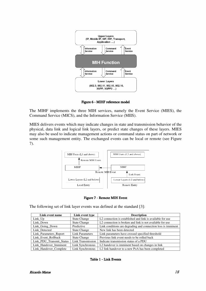
The IEEE 802.21 reference model (see Figure 6) [3] defines three different services all of which centres around the MIHF.
Ricardo MatoRicardo MatoRicardo MatoRicardo Matossss 18
Figure Figure Figure Figure 6666 ---- MIHF reference modelMIHF reference modelMIHF reference modelMIHF reference model
The MIHF implements the three MIH services, namely the Event Service (MIES), the Command Service (MICS), and the Information Service (MIIS).
MIES delivers events which may indicate changes in state and transmission behavior of the physical, data link and logical link layers, or predict state changes of these layers. MIES may also be used to indicate management actions or command status on part of network or some such management entity. The exchanged events can be local or remote (see Figure 7).
Figure Figure Figure Figure 7777 ---- Remote MIH EventRemote MIH EventRemote MIH EventRemote MIH Event
The following set of link layer events was defined at the standard [3]:
Link event name Link event type Description
Link_Up State Change L2 connection is established and link is available for use Link_Down State Change L2 connection is broken and link is not available for use Link_Going_Down Predictive Link conditions are degrading and connection loss is imminent Link_Detected State Change New link has been detected Link_Parameters_Report Link Parameters Link parameters have crossed specified threshold Link_Event_Rollback State Change Previous link event needs to be rolled back Link_PDU_Transmit_Status Link Transmission Indicate transmission status of a PDU Link_Handover_Imminent Link Synchronous L2 handover is imminent based on changes in link Link_Handover_Complete Link Synchronous L2 link handover to a new PoA has been completed
Table Table Table Table 1111 ---- Link E Link E Link E Link Eventsventsventsvents

Ricardo MatoRicardo MatoRicardo MatoRicardo Matossss 19
The following set of MIH events was defined at the standard [3]:
MIH event name
MIH event type
(L) ocal
(R) emote
Description
MIH_Link_Up State Change L, R L2 connection is established and link is available for use
MIH_Link_Down State Change L, R L2 connection is broken and link is not available for use
MIH_Link_Going_Down Predictive L, R Link conditions are degrading and connection loss is imminent
MIH_Link_Detected State Change L, R New link has been detected MIH_Link_Parameters_Report Link Parameters
L, R Link parameters have crossed a specified
threshold and need to be reported MIH_Link_Event_Rollback State Change L, R Previous link event needs to be rolled back MIH_Link_PDU_Transmit_Status Link Transmission L Indicate transmission status of a PDU MIH_Link_Handover_Imminent Link Synchronous
L, R L2 handover is imminent based on either the
changes in the link conditions or additional information available in the network
MIH_Link_Handover_Complete Link Synchronous
L, R L2 link handover to a new PoA has been completed
Table Table Table Table 2222 ---- MIH Events MIH Events MIH Events MIH Events
MICS enables higher layers to control the physical, data link and logical link layers (also known as "lower layers"). The higher layers may control the reconfiguration or selection of an appropriate link through a set of handover commands. The exchanged command can be local or remote (see Figure 8).
Figure Figure Figure Figure 8888 ---- Remote MIH C Remote MIH C Remote MIH C Remote MIH Commandommandommandommand
The following set of link layer commands was defined at the standard [3]:
Link command Comments
Link_Capability_Discover Query and discover the list of supported link layer events and link layer commands Link_Event_Subscribe Subscribe to one or more events from a link Link_Event_Unsubscribe Unsubscribe from a set of link layer events Link_Configure_Thresholds Configure thresholds for Link Parameters Report event Link_Get_Parameters Get parameters measured by the active link Link_Action Request actions on a link layer connection
Table Table Table Table 3333 ---- Link C Link C Link C Link Commandsommandsommandsommands
The following set of MIH commands was defined at the standard [3]:

Ricardo MatoRicardo MatoRicardo MatoRicardo Matossss 20
MIH command
(L)ocal ,
(R)emote Comments
MIH_Get_Link_Parameters L, R Get the status of a link MIH_Configure_Link L, R Configure a link MIH_Scan L, R Scan a list of links MIH_Link_Action L, R Control the behavior of a set of local or remote lower layer links MIH_Net_HO_Candidate_Query R Network may initiate handover and send a list of suggested networks
and associated Points of Attachment MIH_MN_HO_Candidate_Query R Command used by MN to query and obtain handover related
information about possible candidate networks MIH_N2N_HO_Query_Resources R This command is sent by the serving MIHF entity to the target MIHF
entity to allow for resource query, context transfer (if applicable), and handover preparation
MIH_Net_HO_Commit R In this case the network commits to do the handover and sends the choice of selected network and associated PoA
MIH_MN_HO_Commit R Command used by MN to notify the network that a candidate has been committed for handover
MIH_N2N_HO_Commit R Command used by a serving network to inform a target network that a mobile node is about to move toward that network
MIH_MN_HO_Complete R Notification from MIHF of the MN to the target or source MIHF indicating the status of handover completion
MIH_N2N_HO_Complete R Notification from MIHF of the MN to the target or source MIHF indicating the status of handover completion
Table Table Table Table 4444 ---- MIH MIH MIH MIH CCCCommandsommandsommandsommands
MIIS provides a framework and corresponding mechanisms by which the MIHF entity may discover and obtain network information existing within a geographical area to facilitate the handovers, such as, general information and access network specific information, point of attachment specific information and vendor/network specific information. The primitive used by an MIHU to request information from a MIH information server is MIH_Get_Information.
Besides these three type of services (MIES, MICS and MIIS) there are several service management primitives used to the properly configuration of the MIH entities. Next table describes these service management primitives.
Service Management Primitive (L) ocal,
(R) emote Comments
MIH_Capability_Discover L, R Discover the capabilities of a local or peer MIHF MIH_Register R Register with a peer MIHF MIH_DeRegister R Deregister from a peer MIHF MIH_Event_Subscribe L, R Subscribe for one or more MIH events with a local or remote MIHF MIH_Event_Unsubscribe L, R Unsubscribe for one or more MIH events from a local or remote MIHF
TTTTable able able able 5555 ---- Service Service Service Service MMMManagement primitivesanagement primitivesanagement primitivesanagement primitives
The MIHF interfaces with other layers and functional planes using Service Access Points (SAPs). Each SAP consists of a set of service primitives that specify the information to be exchanged and the format of the information exchanges (Figure 9) [3].

Ricardo MatoRicardo MatoRicardo MatoRicardo Matossss 21
Figure Figure Figure Figure 9999 ---- MIHF interfacesMIHF interfacesMIHF interfacesMIHF interfaces
The MIHF can exchange local services or remote services. For this it has to communicate with the remote MIHFs (see Figure 10) using MIH protocol [3]. The MIHF (located in Mobile Node) communication with remote MIHFs (present in Access Network or Core Network) is provided by the MIH_NET_SAP interface, which supports the exchange of MIH information and messages with remote MIHFs. MIH protocol defines message formats for exchanging these messages between peer MIHFs.
Figure Figure Figure Figure 10101010 ---- Communication between different MIHFsCommunication between different MIHFsCommunication between different MIHFsCommunication between different MIHFs
2.3.2.3.2.3.2.3.SummarySummarySummarySummary
In this chapter was presented an overview of the Broadband Wireless technologies giving special emphasis at IEEE 802.16 and their main characteristics. As explained, the 802.16 MAC layer is divided in three sublayers: the Service Specific Convergence Sublayer (CS), the Common Part Sublayer (CPS) and the Privacy Sublayer. In the PHY layer, two main groups are defined: the single carrier and the multi carrier physical layers. The multi carrier physical layer can use OFDM with 256 subcarriers or OFDMA technique provides 2048 subcarriers. In this case, NLOS environments are envisaged and the multipath effect should

Ricardo MatoRicardo MatoRicardo MatoRicardo Matossss 22
be taken into account. The 802.16 equipment features were also described. We also introduce the mobility mechanisms.
As explained, there are several types of handovers, classified by its performance, management, purpose, technologies involved and connectivity. It was depicted the Link Layer mobility in IEEE 802.16e-2005 standard. Because of the necessity of a seamless handover between heterogeneous network, it was explained the IEEE 802.21 standard and its main goals and functionalities.

Ricardo MatoRicardo MatoRicardo MatoRicardo Matossss 23
3.3.3.3.IEEE 802.16 for RealIEEE 802.16 for RealIEEE 802.16 for RealIEEE 802.16 for Real----time Services: IPTV and VoIPtime Services: IPTV and VoIPtime Services: IPTV and VoIPtime Services: IPTV and VoIP
It is widely anticipated that the next generation wireless networks will handle an exponentially larger amount of audio/visual (A/V) content than today’s Internet [17]. As these services operate on an IP network, there are some advantages inherent in the protocol regarding the provision of various services in the same infrastructure. This advantage means a reduction of cost to both the operators and users, also giving opportunity to offer new services valued by customers (interactive). Due to their particular requirements, we perform some tests with Voice over IP (VoIP) and Internet Protocol Television (IPTV).
Our main objective is the investigation of WiMAX (Worldwide Interoperability for Microwave Access) performance in practice and the evaluation of WiMAX as VoIP and video streaming backhaul in point-to-multipoint (PMP) scenarios [28]. We also evaluate Quality of Service (QoS) [9] in our testbed, giving more priority to VoIP because it is a real-time service which has to have low delay and a dedicated bandwidth.
We opted for a point-to-multipoint (PMP) scenario because most of the related work done so far has been done using point-to-point (PTP) scenarios, which is not very real for future use of WiMAX networks in which the source and destination of traffic will be in opposite WiMAX links.
In this chapter we also evaluate VoIP performance over a fixed WiMAX testbed and quantify the benefits from employing application-level aggregation. VoIP aggregation appears to be a powerful method to improve performance and increase capacity utilization.
Section 3.1 provides a brief overview of our testbed. Section 3.2 depicts the work done with VoIP and IPTV without using QoS, whereas section 3.3 relates the same tests but now using QoS. The analysis of VoIP aggregation is provided in section 3.4 and finally, section 3.5 provides a final summary of the chapter.
3.1.3.1.3.1.3.1.Testbeds and MethodologiesTestbeds and MethodologiesTestbeds and MethodologiesTestbeds and Methodologies
At this section will be explained the testbed and the methodology used to evaluate VoIP and IPTV over WiMAX.
3.1.1.3.1.1.3.1.1.3.1.1.TestbedTestbedTestbedTestbed
We employ multiple competing traffic sources over a point-to-multipoint WiMAX topology with two subscriber stations (SSs) and one base station (BS) and measure the capacity of our WiMAX equipment to handle a multitude of VoIP flows between SSs while delivering a variable number of IPTV streams. We measure jitter, throughput, packet loss, and one way delay for LOS (Line of Sight) conditions in our testbed. For the one way

Ricardo MatoRicardo MatoRicardo MatoRicardo Matossss 24
delay measurements we synchronize the clocks of all testbed hosts with a software-only, open source implementation of the IEEE 1588 Precision Time Protocol (PTP) [39].
The implemented testbed is depicted at Figure 11. It illustrates our experimental facility comprising a RedMAX [41] fixed WiMAX BS, operating at the 3.5 GHz frequency band, two subscriber stations (SS1 and SS2), and three PCs. Both SSs are RedMAX equipment. On the BS and SSs sides, we connect seeral terminals to act as traffic sources/sinks.
FiguFiguFiguFigure re re re 11111111 ---- Schematic of our WiMAX testbed Schematic of our WiMAX testbed Schematic of our WiMAX testbed Schematic of our WiMAX testbed
3.1.2.3.1.2.3.1.2.3.1.2.MethodologyMethodologyMethodologyMethodology
In order to obtain the accurate results from our experiments we have to be rigorous. For this our work was done by phases, passing by the configuration, generation of traffic, synchronization of our testbed. This section provides the details of each one of these phases.
• Testbed Configuration
The distances between BS and SSs were 10 m. The measured RSSI values were -48 dBm at both SSs. All tests were performed in our laboratory, where conditions are static, even though there can always be a degree of variance on a wireless link. The modulation scheme employed by SSs was 64 QAM with 3/4 FEC. Table 6 relates the testbed configuration.
Base station and Subscribers Stations RedMAX Frequency band 3.5 GHz Channel bandwidth 3.5 MHz PHY WiMAX 16d, 256 OFDM FDD BS and SS Transmission power 1.0 dBm MAC scheduling Best Effort Downlink Ratio 56/44 Uplink & downlink modulation for SSs 64 QAM (FEC: 3/4) SSs RSSI values -48 dBm BS-SSs distances 10 m
Table Table Table Table 6666 ---- Testbed Configuration Testbed Configuration Testbed Configuration Testbed Configuration

Ricardo MatoRicardo MatoRicardo MatoRicardo Matossss 25
We measure performance under LOS conditions. In our testbed there are three main networks: one for the synchronization between all PCs - 10.240.2.0/8; and the others to perform our tests and measurements - 192.168.11.0/8 (between SS1 and BS) and 192.168.10.0/8 (between SS2 and BS).
• Traffic Generation
o Capturing and emulating IPTV streaming traffic using Jugi’s Traffic
Generator (JTG)
In order to emulate a set of IPTV streams, we got access to 20 minutes of live IPTV unicast transmission and created a packet trace with Wireshark [39]. The captured video stream was in H.264/AVC format (also known as MPEG-4 Part 10) [11] and the accompanying audio stream was encoded in MPEG-1 Audio Layer II (also known as MP2) [50]. The content of the transmission was a music video TV channel and thus configured with video stream at 512 kb/s (360×288, 25 f/s) and the audio at 192 kb/s, emphasizing audio over video quality [27]. The video and audio were collected at the receiver side using Wireshark, recording very low delay and delay variance, no RTP [26] packet loss, and no RTSP [25] message exchanges.
The captured video stream, often with dramatic changes in scenery, visual effects and so on, has a variable bit rate (VBR). The total packet sizes of the video varied greatly, with the major mode at 1492 bytes. It was also emulated the corresponding IPTV audio stream using constant bit rate (CBR) traffic with the total packet size fixed at 634 bytes (including codec payload and RTP/UDP/IP/MAC headers). The video and audio parts of the IPTV traffic are separated and streamed to different ports. This separation allows to study in a straightforward manner the relative performance of VoIP and IPTV A/V over a congested fixed WiMAX link.
Based on the Wireshark trace, it was created new trace files with all packet sizes and interarrival times both for video and audio. Based on these trace files, we “play back” N IPTV A/V streams starting from a random point in the 20-minute long IPTV packet trace, and wrap around if needed. Each run lasts 60 s. We use JTG [48] to generate the trace-driven IPTV streaming traffic. JTG is a simple, flexible, and configurable open source traffic generator, which can be used in a command-line fashion in GNU/Linux. The source of the N A/V streams is located at the PC under the BS, while the sinks are in the domain of SS1.
o Emulating VoIP traffic using JTG
In addition to the N A/V streams, we injected C synthetic duplex, bidirectional VoIP flows with source/sink pairs in the domains of SS1 and SS2 in all of tests, again using JTG. We chose to experiment with Speex [49], an open source audio codec specially designed for VoIP applications over packet switching networks. Speex is designed to be robust against packet loss and has been incorporated in several applications. We emulated C Speex VoIP flows each with a wideband codec bitrate of 12.8 kb/s using JTG. For each VoIP flow, JTG generates 50 packets/s with 32 bytes of codec payload, thus leading to an effective

Ricardo MatoRicardo MatoRicardo MatoRicardo Matossss 26
application bitrate of 17.6 kb/s (including RTP headers). After adding a total of 28 bytes of UDP and IP headers, each JTG instance injects 28.8 kb/s of total emulated Speex CBR traffic into the network.
A single VoIP flow is managed by a single JTG [48] instance running at its own port, so that traces for each stream can be post-processed in detail. Although it is possible to use one JTG instance for receiving more than one stream, it is not possible to separate the logs in a straightforward manner and be able to accurately apportion loss and delay to each flow.
• Use of PTP for host clock synchronization
For high-precision one way delay measurements, accurate clock synchronization is necessary, taking care of both absolute time and clock drift at different hosts in the network. When only round-trip delay measurements are performed, the critical aspect is clock drift only. Lack of accuracy in the absolute time is not harmful. However for the one way delay measurements we are interested, both absolute time and clock drift are important. We opted to use an IEEE 1588 Precision Time Protocol [47] open source server (Precision Time Protocol daemon - PTPd) to synchronize the clocks at all hosts. Similarly with Network Time Protocol (NTP) [24], PTP synchronization messages are sent over the network.
Although PTP injects a very small amount of traffic when compared with the rest of the sources in our tests, it is preferable that PTP signalling does not interfere with the measured traffic. In short, the testbed synchronization was made using a different network, 10.240.2.0/8, where the PC connected to SS2 was the PTPd Server and the other two PCs were the clients. After initializing the PTPd in each machine and waiting the necessary time to the synchronization, the offset between the different host clocks was even lower than 100 µs, which is feasible for our testbed.
With all hosts synchronized within hundreds of µs, this allows for measurement granularity of one to two orders of magnitude larger than the one way delay. At this stage, and wishing to avoid having to deploy (expensive) GPS-clocks on all hosts in the testbed, we are satisfied with the synchronization accuracy provided by the software-only implementation of PTP [35].
3.1.3.3.1.3.3.1.3.3.1.3.Conduct and EConduct and EConduct and EConduct and Experimentxperimentxperimentxperiment
To perform the tests we have to follow the steps described in this section.
• Measuring the maximum WiMAX link capacity
Before proceeding with the measurements, we conducted baseline experiments to determine the maximum throughput that can be attained in our lab testbed. We saturated the fixed WiMAX link and measured the maximum application-level throughput, also called goodput, on the downlink and uplink (from the BS to SS and vice-versa,
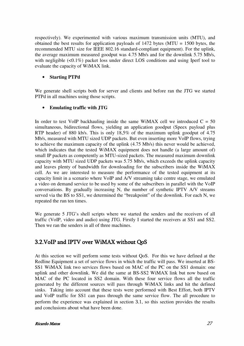
Ricardo MatoRicardo MatoRicardo MatoRicardo Matossss 27
respectively). We experimented with various maximum transmission units (MTU), and obtained the best results for application payloads of 1472 bytes (MTU = 1500 bytes, the recommended MTU size for IEEE 802.16 standard-compliant equipment). For the uplink, the average maximum measured goodput was 4.75 Mb/s and for the downlink 5.75 Mb/s, with negligible (<0.1%) packet loss under direct LOS conditions and using Iperf tool to evaluate the capacity of WiMAX link.
• Starting PTPd
We generate shell scripts both for server and clients and before ran the JTG we started PTPd in all machines using those scripts.
• Emulating traffic with JTG
In order to test VoIP backhauling inside the same WiMAX cell we introduced C = 50 simultaneous, bidirectional flows, yielding an application goodput (Speex payload plus RTP header) of 880 kb/s. This is only 18,5% of the maximum uplink goodput of 4.75 Mb/s, measured with MTU sized UDP packets. But even inserting more VoIP flows, trying to achieve the maximum capacity of the uplink (4.75 Mb/s) this never would be achieved, which indicates that the tested WiMAX equipment does not handle (a large amount of) small IP packets as competently as MTU-sized packets. The measured maximum downlink capacity with MTU sized UDP packets was 5.75 Mb/s, which exceeds the uplink capacity and leaves plenty of bandwidth for downloading for the subscribers inside the WiMAX cell. As we are interested to measure the performance of the tested equipment at its capacity limit in a scenario where VoIP and A/V streaming take centre stage, we emulated a video on demand service to be used by some of the subscribers in parallel with the VoIP conversations. By gradually increasing N, the number of synthetic IPTV A/V streams served via the BS to SS1, we determined the “breakpoint” of the downlink. For each N, we repeated the run ten times.
We generate 5 JTG’s shell scripts where we started the senders and the receivers of all traffic (VoIP, video and audio) using JTG. Firstly I started the receivers at SS1 and SS2. Then we ran the senders in all of three machines.
3.2.3.2.3.2.3.2.VoIP and IPTV over WiMAX without QoSVoIP and IPTV over WiMAX without QoSVoIP and IPTV over WiMAX without QoSVoIP and IPTV over WiMAX without QoS
At this section we will perform some tests without QoS. For this we have defined at the Redline Equipment a set of service flows in which the traffic will pass. We inserted at BS-SS1 WiMAX link two services flows based on MAC of the PC on the SS1 domain: one uplink and other downlink. We did the same at BS-SS2 WiMAX link but now based on MAC of the PC located in SS2 domain. With these four service flows all the traffic generated by the different sources will pass through WiMAX links and hit the defined sinks. Taking into account that these tests were performed with Best Effort, both IPTV and VoIP traffic for SS1 can pass through the same service flow. The all procedure to perform the experience was explained in section 3.1, so this section provides the results and conclusions about what have been done.

Ricardo MatoRicardo MatoRicardo MatoRicardo Matossss 28
3.2.1.3.2.1.3.2.1.3.2.1.ResultsResultsResultsResults
This section presents our measurements in “box-whisker-plots”, or simply boxplots. The box in each figure contains the middle 50% of the measured values. The line in the middle represents the median, the top and bottom of the box correspond to Q3 and Q1, respectively. Values outside the whisker lines, shown as crosses, are considered outliers.
3.2.1.1.3.2.1.1.3.2.1.1.3.2.1.1.Measurements Measurements Measurements Measurements
• Packet Loss
The measured packet loss rates for audio, video and VoIP at SS1 are depicted in Figure 12 a), b) and c) respectively. The box plots show the ten averages of packet loss for the VoIP and A/V streams, as recorded by JTG. The BS-SS1 WiMAX downlink can handle N <= 3 simultaneous A/V streams in parallel with the VoIP traffic with negligible packet loss. When N = 4, packet loss increases rapidly, and even the packet loss average does not exceed 5%, there are occasional situations in which it exceeds, for VoIP, which is unacceptable. Even for the Speex codec, which is the most robust and tolerant to packet loss of the three codecs emulated [49], these situations with this level of losses would be degrading performance considerably. The IPTV video streams suffer packet losses that don’t exceed 5%, for both video and audio, with N<=4, which could be handled satisfactorily by a real-world IPTV client. When N > 4 packet losses exceed 15%, which is also unacceptable. If we turn our attention to the performance of the 50 bidirectional VoIP flows at SS2 (Figure 12 d)), the highest packet loss rate observed at the SS2-BS downlink was 0.04%, which is negligible for Speex [49].
1 2 3 4 50
2
4
6
8
10
12
14
16
18
20
22
Packet
Loss (
%)
Number of independent IPTV streams
1 2 3 4 50
5
10
15
20
25
30
Packet
Loss (
%)
Number of independent IPTV streams
a) Audio at SS1 b) Video at SS1

Ricardo MatoRicardo MatoRicardo MatoRicardo Matossss 29
1 2 3 4 50
5
10
15
20
25
30
35P
acket
Loss (
%)
Number of independent IPTV streams
1 2 3 4 50
5
10
15
20
25
30
35
Packet
Loss (
%)
Number of independent IPTV streams
c) VoIP at SS1 d) VoIP at SS2
Figure Figure Figure Figure 12121212 ---- Measured Packet L Measured Packet L Measured Packet L Measured Packet Loss oss oss oss
• Jitter
Comparing the results at SS1 for audio, video and VoIP (see Figure 13 a), b) and c), respectively) we conclude that audio is the real time traffic that can achieve transmission rates closer to the theoretical rate because of its higher value of jitter. It means that audio is the traffic that is more strongly adjusted at physical level, in order to achieve a transmission rate more close to real. It is followed by VoIP and finally by video which is the traffic that has the lower value for jitter.
1 2 3 4 520
21
22
23
24
25
26
27
28
29
30
Jitte
r (m
s)
Number of independent IPTV streams
1 2 3 4 513
14
15
16
17
18
19
20
21
22
23
Jitte
r (m
s)
Number of independent IPTV streams
a) Audio at SS1 b) Video at SS1

Ricardo MatoRicardo MatoRicardo MatoRicardo Matossss 30
1 2 3 4 515
16
17
18
19
20
21
22
23
24
25Jitte
r (m
s)
Number of independent IPTV streams
1 2 3 4 515
20
25
30
Jitte
r (m
s)
Number of independent IPTV streams
c) VoIP at SS1 d) VoIP at SS2
Figure Figure Figure Figure 13131313 ---- M M M Measured easured easured easured JJJJitter itter itter itter
• Application Throughput
Figure 14 a), b) and c) illustrate the application throughput or goodput, for the three types of traffic (audio, video and VoIP) over the fixed WiMAX link at SS1. The difference between the VBR H.264/AVC encoded video streams and CBR audio and VoIP is visible. The fluctuation of the video stream throughput is more extensive. This is in part due to the variability of the wireless transmission, but also due to the random starting points in the replayed video packet trace. Note that due to the random starting points in the video trace, goodput of video ranges between 500 kb/s and 512 kb/s, when N <= 3, as one would expect. Meanwhile, the throughput of the audio and VoIP streams remains very close to 178 kb/s and 17.6 kb/s, respectively. Note that although the streamer of audio was configured to transmit the audio at 192 kb/s, the captured audio packet trace recorded a somehow smaller bitrate.When N > 3, the capacity of the WiMAX downlink becomes a restrictive factor and the median goodput of all traffic types starts to fall. The spread of the average goodput in different runs starts to increase, as packets are dropped due to backlogs at the WiMAX interface. When the normalized values of goodput are examined, we note that the behaviour of the three different traffic types is practically the same when N > 3, which is the “breakpoint” of the WiMAX downlink for this scenario. At SS2 the goodput (Figure 14 d)) maintains more constant than at SS1, because there is only this type of traffic at SS2. However when we are working with 4 or 5 IPTV streams it has a greater variation. The congestion in the downlink channel at SS1 should have an effect on its uplink channel, in which also passes the VoIP traffic that comes to SS2 and this should be the main reason for this.

Ricardo MatoRicardo MatoRicardo MatoRicardo Matossss 31
1 2 3 4 5140
145
150
155
160
165
170
175
180
185G
oodput
(kb/s
)
Number of independent IPTV streams
1 2 3 4 5
380
400
420
440
460
480
500
520
Goodput
(kb/s
)
Number of independent IPTV streams
a) Audio at SS1 b) Video at SS1
1 2 3 4 510
11
12
13
14
15
16
17
18
19
Goodput
(kb/s
)
Number of independent IPTV streams
1 2 3 4 510
11
12
13
14
15
16
17
18
19
Goodput
(kb/s
)
Number of independent IPTV streams
c) VoIP at SS1 d) VoIP at SS2
Figure Figure Figure Figure 14141414 ---- Measured GMeasured GMeasured GMeasured Goodput oodput oodput oodput
• One Way Delay
The one way packet delays, in the BS-SS1 downlink, as measured by the packet inter-arrival times at SS1, are quite similar across all traffic types, as shown in Figure 15 a), b) and c). For audio and video the one way packet delays walks in the house of 20/25 ms which is typical of the equipment used because it is usually the delay involved in a WiMAX link. For VoIP it is roughly twice 45/50 ms, because this traffic passes two WiMAX links. Overall, mean delay < 60 ms when N <= 3. This range of one way delays can be tolerated by all applications involved in the examined scenario. When N = 4, the median value of the inter-arrival times jumps to over 60/80 ms for audio and video traffics and 80/100 ms for VoIP traffic, as the majority of the received packets have queued through full buffers in the network interfaces of the test system. This range of one way delays can be handled with adequate buffering for the IPTV streams, but not for the VoIP calls. At SS2 (Figure 15 d)), when N <= 3, one way delay is basically the same as in the case of SS1. When N> 3 the delay increases slightly to 50/55 ms which may mean that the WiMAX uplink channel is slightly affected when the downlink channel reaches the breakpoint (N>3), as happened with the goodput.

Ricardo MatoRicardo MatoRicardo MatoRicardo Matossss 32
1 2 3 4 50
10
20
30
40
50
60
70
80
90
100O
ne W
ay D
ela
y (
ms)
Number of independent IPTV streams
1 2 3 4 50
10
20
30
40
50
60
70
80
90
100
One W
ay D
ela
y (
ms)
Number of independent IPTV streams
a) Audio at SS1 b) Video at SS1
1 2 3 4 50
20
40
60
80
100
120
One W
ay D
ela
y (
ms)
Number of independent IPTV streams
1 2 3 4 530
35
40
45
50
55
60
65
70
One W
ay D
ela
y (
ms)
Number of independent IPTV streams
c) VoIP at SS1 d)VoIP at SS2
Figure Figure Figure Figure 15151515 ---- Measured One Way D Measured One Way D Measured One Way D Measured One Way Delay elay elay elay
3.2.2.3.2.2.3.2.2.3.2.2.ConclusionsConclusionsConclusionsConclusions
To sum up, under LOS conditions our testbed can sustain C = 50 emulated bidirectional Speex-encoded VoIP calls within the same WiMAX cell and N = 3 simultaneous emulated IPTV streams with negligible packet loss, adequate application-level throughput, and one way delays within proper bounds. Recall that our BS does not employ any QoS mechanisms and these results are based on the Best Effort fixed WiMAX profile.
3.3.3.3.3.3.3.3.VoIP and IPTV over WiMAX with QoSVoIP and IPTV over WiMAX with QoSVoIP and IPTV over WiMAX with QoSVoIP and IPTV over WiMAX with QoS
At this point we were interested to study the comportment of the WiMAX equipment using classes of traffic. For this we used the testbed of the previous section but we have allocated to VoIP traffic higher priority than to IPTV traffic. We opted first to have no background traffic beyond the VoIP and IPTV traffic. At a second phase we inserted Best Effort (BE) traffic at our testbed.

Ricardo MatoRicardo MatoRicardo MatoRicardo Matossss 33
3.3.1.3.3.1.3.3.1.3.3.1.NoNoNoNo Background traffic Background traffic Background traffic Background traffic
Because of the handicaps of the equipment used, the higher class of service we can give to a kind of traffic will be rtPS. VoIP is a real time type of traffic and has to be associated a low delay. Because of this we associated it with rtPS service class but with a minimum of bandwidth allocated of 1440 Kb / s (50 flows of VoIP x 28.8 Kb / s). For the IPTV we decided to assign the rtPS service class but without associated minimum bandwidth, because IPTV may have associated some delay.
To perform the QoS tests we had the same services flows as before where the MAC traffic pass (those services flows were associated at the lower class of service). To differentiate the VoIP and IPTV traffic, we create four services flows at SS1 and SS2 domains (twice uplink and twice downlink) based on IPv4 address of the PCs on these domains, in which VoIP traffic will pass. On the other hand we also create a downlink service flow on SS1 domain but in this case associated with a lower class of traffic, in which IPTV traffic will pass. The all procedure to perform the experience was explained in section 3.1, so this section provides the results and conclusions about what have been done.
3.3.1.1.ResultsResultsResultsResults
At this section our measurements are presented in the following subsections in “box-whisker-plots”, or simply boxplots.
3.3.1.1.1.3.3.1.1.1.3.3.1.1.1.3.3.1.1.1.MeasurementsMeasurementsMeasurementsMeasurements
• PPPPacket Lacket Lacket Lacket Lossossossoss
Accordingly with the results at SS1 for audio and video (Figure 16 a) and b)) the BS-SS1 WiMAX downlink can handle N <= 3 simultaneous A/V streams in parallel with the VoIP traffic with negligible packet loss as depicted in section 3.2.1.1. When N >= 4, packet loss for IPTV increases rapidly, which is unacceptable. The packet loss values for video and audio are higher than in the tests performed only with Best Effort because in this case the priority for IPTV traffic is lower than for VoIP traffic what makes the traffic IPTV sometimes have to wait, for the WiMAX channel is free, to be sent immediately. It causes the increase of packet loss because the queue in the WiMAX segment for IPTV traffic will saturate earlier than previously. For VoIP the results are depicted in Figure 16 c) and d). These results were expected because VoIP is the most priority traffic and so it had small packet loss.

Ricardo MatoRicardo MatoRicardo MatoRicardo Matossss 34
1 2 3 4 50
2
4
6
8
10
12
14
16
18
20
22P
acket
Loss (
%)
Number of independent IPTV streams
1 2 3 4 50
5
10
15
20
25
30
35
40
Packet
Loss (
%)
Number of independent IPTV streams
a) Audio at SS1 b) Video at SS1
1 2 3 4 50
5
10
15
20
25
30
35
Packet
Loss (
%)
Number of independent IPTV streams
1 2 3 4 50
5
10
15
20
25
30
35
Packet
Loss (
%)
Number of independent IPTV streams
c) VoIP at SS1 d) VoIP at SS2
Figure Figure Figure Figure 16161616 ---- MMMMeasured Packet Leasured Packet Leasured Packet Leasured Packet Loss oss oss oss
• JitterJitterJitterJitter
The jitter results described in Figure 17 a), b) c) and d) are similar to the ones described in section 3.2.1.1, except the variation of the jitter for VoIP on both sides. In this case the VoIP jitter is more constant because it was attributed to VoIP the higher service class.
1 2 3 4 520
21
22
23
24
25
26
27
28
29
30
Jitte
r (m
s)
Number of independent IPTV streams
1 2 3 4 513
14
15
16
17
18
19
20
21
22
23
Jitte
r (m
s)
Number of independent IPTV streams
a) Audio at SS1 b) Video at SS1

Ricardo MatoRicardo MatoRicardo MatoRicardo Matossss 35
1 2 3 4 515
16
17
18
19
20
21
22
23
24
25Jitte
r (m
s)
Number of independent IPTV streams
1 2 3 4 515
16
17
18
19
20
21
22
23
24
25
Jitte
r (m
s)
Number of independent IPTV streams
c) VoIP at SS1 d) VoIP at SS2
Figure Figure Figure Figure 17171717 ---- Measured JMeasured JMeasured JMeasured Jitter itter itter itter
• Application TApplication TApplication TApplication Throughputhroughputhroughputhroughput
The application goodput results provide the same conclusions than the packet loss results. In result of the higher service class for VoIP this kind of traffic has the bandwidth of WiMAX segment that it needs, whatever the number of IPTV streams, as we can see at Figure 18 c) and d). When N >= 4, goodput for IPTV (Figure 18 a) and b)) decreases rapidly, which is unacceptable. The IPTV lower priority when compared with VoIP traffic means that it is assigned a lower bandwidth at WiMAX link when it is being requested simultaneously by both traffics (VoIP and IPTV).
1 2 3 4 5140
145
150
155
160
165
170
175
180
185
Goodput
(kb/s
)
Number of independent IPTV streams
1 2 3 4 5
380
400
420
440
460
480
500
520
Goodput
(kb/s
)
Number of independent IPTV streams
a) Audio at SS1 b) Video at SS1

Ricardo MatoRicardo MatoRicardo MatoRicardo Matossss 36
1 2 3 4 510
11
12
13
14
15
16
17
18
19G
oodput
(kb/s
)
Number of independent IPTV streams
1 2 3 4 510
11
12
13
14
15
16
17
18
19
Goodput
(kb/s
)
Number of independent iptv streams in downlink
c) VoIP at SS1 d) VoIP at SS2
Figure Figure Figure Figure 18181818 ---- Measured GMeasured GMeasured GMeasured Goodput oodput oodput oodput
• One Way Delay
When N >= 4, one way delay for IPTV (Figure 19 a) and b)) increases faster compared with the results of section 3.2.1.1 in which we performed tests with Best Effort. In this case the priority for IPTV traffic is lower than for VoIP traffic what makes the IPTV sometimes have to wait a long time, for the WiMAX channel is free, to be sent. For VoIP the results are depicted in Figure 19 c) and d). These results were expected because VoIP is the most priority traffic. The delay is typical of the equipment used because it is usually the delay involved in a WiMAX link.
1 2 3 4 50
20
40
60
80
100
120
140
160
180
200
One W
ay D
ela
y (
ms)
Number of independent IPTV streams
1 2 3 4 50
20
40
60
80
100
120
140
160
180
200
One W
ay D
ela
y (
ms)
Number of independent IPTV streams
a) Audio at SS1 b) Video at SS1

Ricardo MatoRicardo MatoRicardo MatoRicardo Matossss 37
1 2 3 4 50
20
40
60
80
100
120
One W
ay D
ela
y (
ms)
Number of independent IPTV streams
1 2 3 4 50
20
40
60
80
100
120
One W
ay D
ela
y (
ms)
Number of independent IPTV streams
c) VoIP at SS1 d) VoIP at SS2
Figure Figure Figure Figure 19191919 ---- Measured One W Measured One W Measured One W Measured One Wayayayay D D D Delayelayelayelay
3.3.1.2.ConclusionsConclusionsConclusionsConclusions
To sum up, our testbed can also sustain C = 50 emulated bidirectional Speex encoded VoIP calls within the same WiMAX cell and N = 3 simultaneous emulated IPTV streams with negligible packet loss, adequate application-level throughput, and one way delays within proper bounds. Nevertheless, at this section, our BS employed QoS mechanisms, attributing higher priority to VoIP traffic which provides it good quality not depending in number of IPTV streams. IPTV deteriorates its quality when we try to insert in the WiMAX link 4 or 5 streams, behaving them as traffic Best Effort when the VoIP is not present.
3.3.2.3.3.2.3.3.2.3.3.2.Background Traffic in Best EffortBackground Traffic in Best EffortBackground Traffic in Best EffortBackground Traffic in Best Effort
At this point we were interested to study the comportment of the WiMAX equipment using classes of traffic mixed with Best Effort. For these tests we added best effort traffic from SS2 to SS1 in order to verify the behaviour of this traffic when there is traffic with higher priority simultaneously. For this we have to change a little our testbed as we can see in Figure 20.

Ricardo MatoRicardo MatoRicardo MatoRicardo Matossss 38
Figure Figure Figure Figure 20202020 ---- New schematic of our WiMAX testbed New schematic of our WiMAX testbed New schematic of our WiMAX testbed New schematic of our WiMAX testbed
Note that the background traffic in Best Effort is from SS2 to SS1 and it is emulated at the same manner than for VoIP traffic with QoS, this is, we introduced C = 50 simultaneous VoIP flows from SS2 to SS1, but passing through the lower class of traffic, in order to differentiate it with the VoIP traffic with higher priority. The VoIP and IPTV traffic with different priorities remained as the last section, maintaining the higher priority for VoIP. The service flows established at the equipment remained the same. As we want to add Best Effort traffic, we can use the services flows based on MAC address defined before. Those services flows were associated at the lower class of service which is what we want. The all procedure to perform the experience was explained in section 3.1, so this section provides the results and conclusions about what have been done.
3.3.2.1.ResultsResultsResultsResults
At this section our measurements are presented in the following subsections in “box-whisker-plots”, or simply boxplots.
3.3.2.1.1.3.3.2.1.1.3.3.2.1.1.3.3.2.1.1.MeasurementsMeasurementsMeasurementsMeasurements
• Packet Loss
The packet loss results at SS1 and SS2 (Figure 21) are similar to the results obtained in the section 3.3.1.1.1. This was expectable because the only difference introduced was background traffic as Best Effort which doesn’t interfere with the more priority traffic. However this Best Effort traffic presents a high level of packet loss, as we expected, since we introduce 3 IPTV streams in WiMAX link. Note that with 5 IPTV streams it keeps almost 100% of packet loss. It demonstrates that good quality in Best Effort is only possible when the link isn’t saturated. Since it saturate the priority is given at classes of traffic with higher priority.

Ricardo MatoRicardo MatoRicardo MatoRicardo Matossss 39
1 2 3 4 50
2
4
6
8
10
12
14
16
18
20
22P
acket
Loss (
%)
Number of independent IPTV streams
1 2 3 4 50
5
10
15
20
25
30
35
Packet
Loss (
%)
Number of independent IPTV streams
a) Audio at SS1 b) Video at SS1
1 2 3 4 50
5
10
15
20
25
30
35
Packet
Loss (
%)
Number of independent IPTV streams
1 2 3 4 50
10
20
30
40
50
60
70
80
90
100
Packet
Loss (
%)
Number of independent IPTV streams
c) VoIP with QoS at SS1 d) VoIP with BE at SS1
1 2 3 4 50
5
10
15
20
25
30
35
Packet
Loss (
%)
Number of independent IPTV streams
e) VoIP at SS2
Figure Figure Figure Figure 21212121 ---- Measured Packet L Measured Packet L Measured Packet L Measured Packet Loss oss oss oss
• Jitter
The jitter results are similar with the section 3.3.1.1.1 results, as we explained before, except for the Best Effort traffic that presents a high level of jitter which is unacceptable

Ricardo MatoRicardo MatoRicardo MatoRicardo Matossss 40
(see Figure 22). This presents the same problem as before, which is the lower priority of Best Effort traffic compared with other classes of traffic.
1 2 3 4 5
50
100
150
200
250
300
350
400
450
500
550
Jitte
r (m
s)
Number of independent IPTV streams
Figure Figure Figure Figure 22222222 ---- Measure Measure Measure Measured Jd Jd Jd Jitter at SS1 for VoIP with BEitter at SS1 for VoIP with BEitter at SS1 for VoIP with BEitter at SS1 for VoIP with BE
• Application Throughput
The goodput results are similar when compared to the results of the section 3.3.1.1.1, as we explained before, except for the Best Effort traffic (see Figure 23) which has no bandwidth available when the WiMAX link starts to saturate because of its lower priority.
1 2 3 4 50
2
4
6
8
10
12
14
16
18
Goodput
(kb/s
)
Number of independent IPTV streams
Figure Figure Figure Figure 23232323 ---- Measured G Measured G Measured G Measured Goodput at SS1 for VoIP with BEoodput at SS1 for VoIP with BEoodput at SS1 for VoIP with BEoodput at SS1 for VoIP with BE
• One Way Delay
The one way delay results are similar with the section 3.3.1.1.1 results, as we explained before, except for the Best Effort traffic (see Figure 24) which has to wait a lot of time to be attended when the WiMAX link starts to saturate because of its lower priority.

Ricardo MatoRicardo MatoRicardo MatoRicardo Matossss 41
1 2 3 4 50
1000
2000
3000
4000
5000
6000
7000
8000
9000
10000
One W
ay D
ela
y (
ms)
Number of independent IPTV streams
Figure Figure Figure Figure 24242424 ---- Measured One Way D Measured One Way D Measured One Way D Measured One Way Delay at SS1 for VoIP with BEelay at SS1 for VoIP with BEelay at SS1 for VoIP with BEelay at SS1 for VoIP with BE
3.3.2.2.ConclusionsConclusionsConclusionsConclusions
At this section, our BS keep maintaining to employ QoS mechanisms, attributing higher priority to VoIP traffic which provides that it keeps good quality for VoIP not depending in number of IPTV streams. IPTV deteriorates its quality when we try to insert in the WiMAX link 4 or 5 streams because of its lower priority. But the main difference between this section and the section 3.3.1 was the background traffic as Best Effort which becomes to have bad quality since we introduce 3 IPTV streams in the WiMAX link.
3.4.3.4.3.4.3.4.VoIP Aggregation over WiMAXVoIP Aggregation over WiMAXVoIP Aggregation over WiMAXVoIP Aggregation over WiMAX
In this section we will evaluate VoIP performance over fixed WiMAX using synthetic traffic generation. We quantify both uplink and downlink performance for G.723.1 emulated VoIP traffic in terms of cumulative goodput, packet loss, and mean opinion scores, based on the ITU-T E Model [46]. Moreover, we empirically investigate the benefits from employing application-level VoIP aggregation when using fixed WiMAX as a backhaul. Aggregation appears as a promising approach for increasing the overall network efficiency and resource utilization. If we use objective mean opinion scores (MOS) as the main gauge of overall performance, application-layer aggregation appears to be the best scheme, allowing our fixed WiMAX testbed to sustain nearly three times more flows in the downlink and over two times more flows in the uplink than when no aggregation is used, at comparable MOS values [34].
3.4.1.3.4.1.3.4.1.3.4.1.Testbed and Testbed and Testbed and Testbed and MethodologyMethodologyMethodologyMethodology
At this section will be explained the testbed and the methodology used to evaluate VoIP Aggregation over WiMAX.
3.4.1.1.3.4.1.1.3.4.1.1.3.4.1.1.TestbedTestbedTestbedTestbed

Ricardo MatoRicardo MatoRicardo MatoRicardo Matossss 42
Figure 25 retracts our new testbed. The main difference between this and the one used to perform the previous tests is that it is a point-to-point testbed. This is not an important fact in order to study VoIP Aggregation and give us the possibility to evaluate the performance of uplink and downlink WiMAX channels, separately.
Figure Figure Figure Figure 25252525 ---- Schematic of our WiMAX testbed Schematic of our WiMAX testbed Schematic of our WiMAX testbed Schematic of our WiMAX testbed
3.4.1.2.3.4.1.2.3.4.1.2.3.4.1.2.MethodologyMethodologyMethodologyMethodology
In order to obtain the accurate results from our experiments we have to be rigorous. For this our work was done by phases, passing by the configuration, generation of traffic, synchronization of our testbed. This section provides the details of each one of these phases.
• Testbed Configuration
The testbed configuration follows the same steps described in section 3.1.2.
• Traffic Generation
o Emulating VoIP traffic using JTG
For this empirical study, we generate synthetic traffic load based on the ITU-T G.723.1 codec [51]. This is a low-rate codec, for real time encoding and decoding, and with good voice quality. A single G.723.1 frame can be 24 octets, which translates into an application-only transmission rate of 6.3 kb/s, or 20 octets (5.3 kb/s), or, finally, 4 octets only. The latter type of payloads corresponds to Silence Insertion Descriptor (SID) frames, used to specify comfort noise parameters, whereas the former two are used to transmit actual voice data. We do not consider SID frames in this study. The higher bitrate variant offers better voice quality compared to the lower bitrate one, and is our chosen variant for these tests.
Typically, a single G.723.1 sample is encapsulated in an RTP [26] packet and sent over UDP/IP. When the RTP, UDP, and IPv4 standard headers, consisting of 12, 8, and 20 bytes, respectively, are appended to the 24 octets codec payload, the total actual packet size is 64 bytes. This raises the overall VoIP transmission rate to 17 kb/s. In our setup, a single VoIP flow generated by JTG injects a 64-byte packet (carrying a single audio

Ricardo MatoRicardo MatoRicardo MatoRicardo Matossss 43
sample) every 30 ms. The G.723.1 small frame size and low bandwidth requirement provides a very good benchmark for investigating the gains of VoIP aggregation.
We inject multiple parallel traffic streams using scripts we developed so that testbed hosts can act as VoIP senders and receivers.
Figure Figure Figure Figure 26262626 ---- G.723.1 sample application G.723.1 sample application G.723.1 sample application G.723.1 sample application----layer aggregationlayer aggregationlayer aggregationlayer aggregation
Figure 26 illustrates application-layer VoIP aggregation. Here, a single RTP packet carries more than one G.723.1 samples, which is explicitly allowed by the RTP specification. In our tests, we experimented with two levels of application-level aggregation carrying two or three samples in a single RTP packet. For “L1 aggregation”, an 88-byte packet is generated every 60 ms. In the case where three G.723.1 samples are aggregated (“L2 aggregation”), a 112-byte packet is generated every 90 ms.
• Performance Metrics
For the purposes of this study we consider three main metrics: (a) cumulative goodput, (b) packet and audio sample loss, and (c) the objective mean opinion score (MOS). MOS expresses the quality of the VoIP transmission in a single number in the 1-5 range (1: worst quality; 5: best quality).
We calculate MOS values based on the well-known transmission rating factor R, or “R-Score” [52], which is derived from packet loss and delay measurements as follows [53]:
)(eds 1A + I - I - I- R = R 0
where R0 represents the basic signal-to-noise ratio, including noise sources such as circuit noise and room noise. Is captures the effect of impairments to the voice signal, and Id factors in impairments due to delays. Ie takes into account the effects caused by using low-bitrate codecs. The expectation factor A compensates the impairment in the case that the user has access to alternatives. In conventional (wired) environments A is equal to 0. Besides A, the rest of the factors can be subdivided if needed. In our case there is no need to so, as we assume default values for speech transmission. Therefore, we simplify Equation (1) as follows:
(2) l) (c,I - (d)I - 94.2 = R ed
Ie is a function of the used codec (c) and the loss rate (l):
l) · + log(1 · + = l) (c,I 321e γγγ

Ricardo MatoRicardo MatoRicardo MatoRicardo Matossss 44
where γ1, γ2, γ3 are specified from the codec. For G.723.1, we have γ1 = 15, γ2 = 90, and γ3 = 0.05 [54]. Id depends on the delays (d) [53]:
Id(d) = 0.024 d + 0.11 (d − 177.3)H(d − 177.3)
H(x) is the step function (H(x) = 1 if, x ≥ 0 and 0 if x < 0) [55].
The ITU E-Model also specifies the non-linear mapping to the (listening) MOS:
MOS = 1 + 0.035R + 7 · 10−6 R(R − 60) (100 − R) (3)
• Use of PTP for host clock synchronization
The host clock synchronization follows the same steps described in section 3.1.2.
3.4.2.3.4.2.3.4.2.3.4.2.ResultsResultsResultsResults
As mentioned earlier, the main goal of this study is to separately quantify the maximum downlink and uplink performance of the tested RedMAX WiMAX equipment for G.723.1 encoded VoIP data traffic in a laboratory environment. We started with a small traffic load yielding no losses and excellent MOS, and increased gradually the offered load measuring the gradual degradation. We continued well beyond the maximum capacity of the tested link in order to see how the system behaves when its maximum capacity is exceeded. As a result from the measurements, the amount of G.723.1 encoded VoIP flows the link can support without seriously decreasing the received voice quality, was identified. Each of the test runs lasted 100 seconds.
We generate 4 shell scripts where we started the senders and the receivers of VoIP traffic using JTG. Firstly I started the receiver at SS and the sender at BS to study the downlink capacity of the channel. Afterwards I started the receiver at BS and the sender at SS to study the uplink capacity of the channel.
At WiMAX equipment we have to generate two service flows (uplink and downlink) based on MAC address of the PC located on the SS domain.
This section provides the results obtained.
3.4.2.1.3.4.2.1.3.4.2.1.3.4.2.1.Measurements Measurements Measurements Measurements
• Cumulative Goodput
The small size of single-sample G.723.1 VoIP packets has a substantial effect on the cumulative goodput and the number of flows that can be supported on the downlink and uplink of our WiMAX testbed. Figure 27 shows that, the maximum downlink goodput for

Ricardo MatoRicardo MatoRicardo MatoRicardo Matossss 45
non-aggregated VoIP traffic is no more than 2.7 Mbits/s. In uplink, the goodput saturation point is reached already at 1.75 Mbits/s, as can be seen in Figure 28. This very poor performance is mainly attributed to the overhead introduced by the RTP, UDP and IP headers, when compared to the size of the actual VoIP codec payload. Indeed, every 64 byte VoIP packet carries only 24 bytes of application payload (total overhead of 167%).
When application-layer aggregation is used, the negative effects of, on the one hand, excessive header overhead, and on the other, the more frequent packet generation, can be mitigated. Figure 27 and Figure 28 show that application-layer VoIP aggregation outperforms the simple audio sample encapsulation in both downlink and uplink. When employing L1 aggregation (two codec samples in an IP packet) the header overhead drops to 83%. As a result, 450 flows can be injected into the downlink, instead of 275 in the non-aggregated runs.
100 150 200 250 300 350 400 450 500 550 600500
1000
1500
2000
2500
3000
3500
4000
Number of concurrent VoIP flows
Cum
ula
tive G
oodput
(kbit/s
)
G.723.1
Application/host-based L1 aggregation
Application/host-based L2 aggregation
Figure Figure Figure Figure 27272727 ---- Cumulative downlink G Cumulative downlink G Cumulative downlink G Cumulative downlink Goodputoodputoodputoodput
100 150 200 250 300 350 400 450 500500
1000
1500
2000
2500
3000
3500
Number of concurrent VoIP flows
Cum
ula
tive G
oodput
(kbit/s
)
G.723.1
Application/host-based L1 aggregation
Application/host-based L2 aggregation
Figure Figure Figure Figure 28282828 ---- Cumulative uplink G Cumulative uplink G Cumulative uplink G Cumulative uplink Goodputoodputoodputoodput

Ricardo MatoRicardo MatoRicardo MatoRicardo Matossss 46
When L2 application-layer aggregation is used (3 codec samples/IP packet), we need 550 flows to saturate the fixed WiMAX downlink. This means that L2 aggregation effectively doubles the number of VoIP flows that can be served in the downlink. This is a direct result of limiting the header overhead to 55%. The L2 cumulative goodput is nearly 4 Mbits/s.In the uplink, the gains in terms of VoIP flows that can be served at the cumulative goodput saturation point are even greater. With L1, more than 340 flows can be sustained instead of only 190 in the non-aggregated VoIP scenario. With L2, the number of VoIP flows effectively is more than the double of non-aggregated VoIP scenario. In terms of cumulative goodput, L2 can deliver almost 3.1 Mbits/s.
Although the goodput performance gains attained with application-layer aggregation are remarkable, the total goodput over the fixed WiMAX link with several hundred of VoIP flows is substantially lower than our baseline measurements with MTU-sized packets (see section 3.1.3). Even with L2 application-layer aggregation, the cumulative downlink goodput is roughly only 2/3 of the single-flow baseline downlink goodput of nearly 5.75 Mbits/s, measured with 1500-byte packets. This is a significant reduction. The case in the uplink is similar (4.75 Mbits/s vs. 3.1 Mbits/s).
• Packet and Sample Loss
Figure 29 and Figure 30 illustrate the measured packet loss rates as we increase the number of concurrent flows in the fixed WiMAX downlink and uplink, respectively. When no aggregation is employed, our testbed downlink can sustain only approximately 270 concurrent VoIP flows with negligible loss. In the uplink about 195 flows can be sustained with negligible loss. If we introduce more flows, the uplink emerges as a clear bottleneck. With 300 flows, the downlink loss rate rises to 4% and with 315 flows we exceed the threshold of 5% drops. In general, drop rates less than 5% are tolerable for G.723.1 VoIP clients. Drops in excess of 10% are unacceptable. In the uplink, injecting 210 flows is enough for crossing the 5% threshold.
100 150 200 250 300 350 400 450 500 550 6000
2
4
6
8
10
12
14
16
18
Number of concurrent VoIP flows
Packet
Loss (
%)
G.723.1
Application/host-based L1 aggregation
Application/host-based L2 aggregation
Figure Figure Figure Figure 29292929 ---- Average downlink Packet L Average downlink Packet L Average downlink Packet L Average downlink Packet Lossossossoss

Ricardo MatoRicardo MatoRicardo MatoRicardo Matossss 47
100 150 200 250 300 350 400 450 5000
2
4
6
8
10
12
14
16
Number of concurrent VoIP flows
Packet
Loss (
%)
G.723.1
Application/host-based L1 aggregation
Application/host-based L2 aggregation
Figure Figure Figure Figure 30303030 ---- Average uplink Packet L Average uplink Packet L Average uplink Packet L Average uplink Packet Lossossossoss
The drops in the uplink are distributed very unevenly between the concurrent flows. When some flows experience near-zero packet loss, others may end up losing up to 90% of their packets. This very interesting behaviour appears, especially, with small packets, such as non-aggregated VoIP packets.
When we consider application-layer aggregation, both L1 and L2 outperform the straightforward single-sample transmission. With L1, no packets are dropped until we start introducing 400 concurrent flows in the downlink and nearly 330 flows in the uplink. With L2, drops start to occur only after we inject 540 flows into the downlink and more than 420 flows into the uplink. The 5% packet loss threshold is exceeded with L1 aggregation with 460 flows in the downlink and nearly 350 flows in the uplink. With L2 aggregation we need to inject more than 570 and 450 flows in the downlink and uplink, respectively, in order to start observing an average of 5% packet loss.
However, since we are aggregating samples, it is fairer to compare the actual sample loss rates of the different schemes. That is, when considering L1 aggregation, for example, a packet loss rate of x% corresponds to an effective sample loss rate of 2x%. For L2, the effective sample loss rate is 3x%. The effective loss rate for downlink is shown in Figure
31 whereas corresponding uplink values can be seen in Figure 32.

Ricardo MatoRicardo MatoRicardo MatoRicardo Matossss 48
100 150 200 250 300 350 400 450 500 550 6000
5
10
15
20
25
30
35
Number of concurrent VoIP flows
Sam
ple
Loss (
%)
G.723.1
Application/host-based L1 aggregation
Application/host-based L2 aggregation
Figure Figure Figure Figure 31313131 ---- Average downlink Sample L Average downlink Sample L Average downlink Sample L Average downlink Sample Lossossossoss
100 150 200 250 300 350 400 450 5000
5
10
15
20
25
30
35
40
45
Number of concurrent VoIP flows
Sam
ple
Loss (
%)
G.723.1
Application/host-based L1 aggregation
Application/host-based L2 aggregation
Figure Figure Figure Figure 32323232 ---- Average uplin Average uplin Average uplin Average uplink Sample Lk Sample Lk Sample Lk Sample Lossossossoss
The clear winner with respect to sustaining more flows without any loss is application-layer aggregation in both the uplink and the downlink. In the downlink with L1 application-layer aggregation more than 400 flows can be sustained without any drops; with L2, more than 540 flows can be sustained. These are the improvements over the non-aggregated results. More importantly, perhaps, this is achieved while saturating the testbed WiMAX link, and using more wireless resources for actual user data (recall Figure 27 and Figure 28). If the WiMAX link operator is willing to accommodate more flows at a slightly degraded service level, L1 aggregation can sustain nearly 470 flows with less than 10% sample loss rate, while L2 aggregation raises the same bar to higher than 570 flows. In the uplink, L2 application-layer aggregation increases the tolerable flow amount by nearly 25% when compared with the corresponding L1 results: L2 can allow for up to 440 flows to be sustained. If the one way end-to-end delay, over and above the buffering delay introduced by the aggregation scheme is in the order of 60 to 90 ms, application-layer
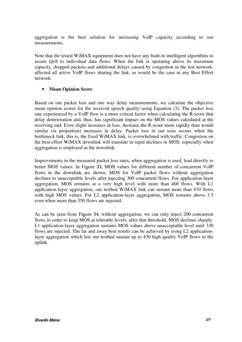
Ricardo MatoRicardo MatoRicardo MatoRicardo Matossss 49
aggregation is the best solution for increasing VoIP capacity according to our measurements.
Note that the tested WiMAX equipment does not have any built-in intelligent algorithms to assure QoS to individual data flows. When the link is operating above its maximum capacity, dropped packets and additional delays caused by congestion in the test network, affected all active VoIP flows sharing the link, as would be the case in any Best Effort network.
• Mean Opinion Score
Based on our packet loss and one way delay measurements, we calculate the objective mean opinion scores for the received speech quality using Equation (3). The packet loss rate experienced by a VoIP flow is a more critical factor when calculating the R-score that delay deterioration and, thus, has significant impact on the MOS values calculated at the receiving end. Even slight increases in loss, decrease the R-score more rapidly than would similar (in proportion) increases in delay. Packet loss in our tests occurs when the bottleneck link, this is, the fixed WiMAX link, is overwhelmed with traffic. Congestion on the best-effort WiMAX downlink will translate in rapid declines in MOS, especially when aggregation is employed in the downlink.
Improvements in the measured packet loss rates, when aggregation is used, lead directly to better MOS values. In Figure 33, MOS values for different number of concurrent VoIP flows in the downlink are shown. MOS for VoIP packet flows without aggregation declines to unacceptable levels after injecting 300 concurrent flows. For application-layer aggregation, MOS remains at a very high level with more than 400 flows. With L1 application-layer aggregation, our testbed WiMAX link can sustain more than 410 flows with high MOS values. For L2 application-layer aggregation, MOS remains above 3.5 even when more than 550 flows are injected.
As can be seen from Figure 34, without aggregation, we can only inject 200 concurrent flows in order to keep MOS at tolerable levels; after that threshold, MOS declines sharply. L1 application-layer aggregation sustains MOS values above unacceptable level until 330 flows are injected. The far and away best results can be achieved by using L2 application-layer aggregation which lets our testbed sustain up to 430 high quality VoIP flows in the uplink.

Ricardo MatoRicardo MatoRicardo MatoRicardo Matossss 50
100 200 300 400 500 6000.5
1
1.5
2
2.5
3
3.5
4
4.5
Number of concurrent VoIP flows
Mean O
pin
ion S
core
G.723.1
Application/host-based L1 aggregation
Application/host-based L2 aggregation
Figure Figure Figure Figure 33333333 ---- Downlink M Downlink M Downlink M Downlink Mean ean ean ean OOOOpinion pinion pinion pinion SSSScorecorecorecore
50 100 150 200 250 300 350 400 450 500 5500.5
1
1.5
2
2.5
3
3.5
4
4.5
Number of concurrent VoIP flows
Mean O
pin
ion S
core
G.723.1
Application/host-based L1 aggregation
Application/host-based L2 aggregation
Figure Figure Figure Figure 34343434 ---- Uplink M Uplink M Uplink M Uplink Mean ean ean ean OOOOpinion pinion pinion pinion SSSScorecorecorecore
If we use MOS as the only gauge of overall performance, application-layer aggregation seems to be the best scheme, allowing our fixed WiMAX testbed to sustain nearly two times more flows in the uplink and in the downlink than when no aggregation is used, at comparable level of MOS values.
3.4.3.3.4.3.3.4.3.3.4.3.ConclusionConclusionConclusionConclusionssss
We considered the performance of aggregated and non-aggregated VoIP over a fixed WiMAX testbed. We measured the performance of different transmissions schemes in terms of cumulative goodput, packet and sample loss rates, and calculated the objective mean opinion scores using the R-Score specified by ITU. We found that VoIP flows carrying single sample payloads generated by the G.723.1 codec are clearly

Ricardo MatoRicardo MatoRicardo MatoRicardo Matossss 51
underperforming in both uplink and downlink. Indeed, the header overhead introduced by RTP, UDP and IP lead to significant waste in wireless bandwidth resources. The strategy of sending a single sample encapsulated in an RTP/UDP/IP packet is, to say the least, suboptimal.
We found that, application layer VoIP aggregation can do more than double the number of VoIP flows in the downlink, without any network or hardware support. The results are of the same order for the uplink as well.
3.5.3.5.3.5.3.5.SummarySummarySummarySummary
With these measurements we tried to understand what is realistically possible using off-the-shelf fixed WiMAX equipment today. We conclude that it allows us to provisioned QoS for different type of traffics.
We evaluate, not only, WiMAX as VoIP and IPTV streaming backhaul in a point-to-multipoint scenario, but also, conclude that VoIP aggregation appears to be a powerful method to improve performance and increase capacity utilization in a point-to-point scenario.
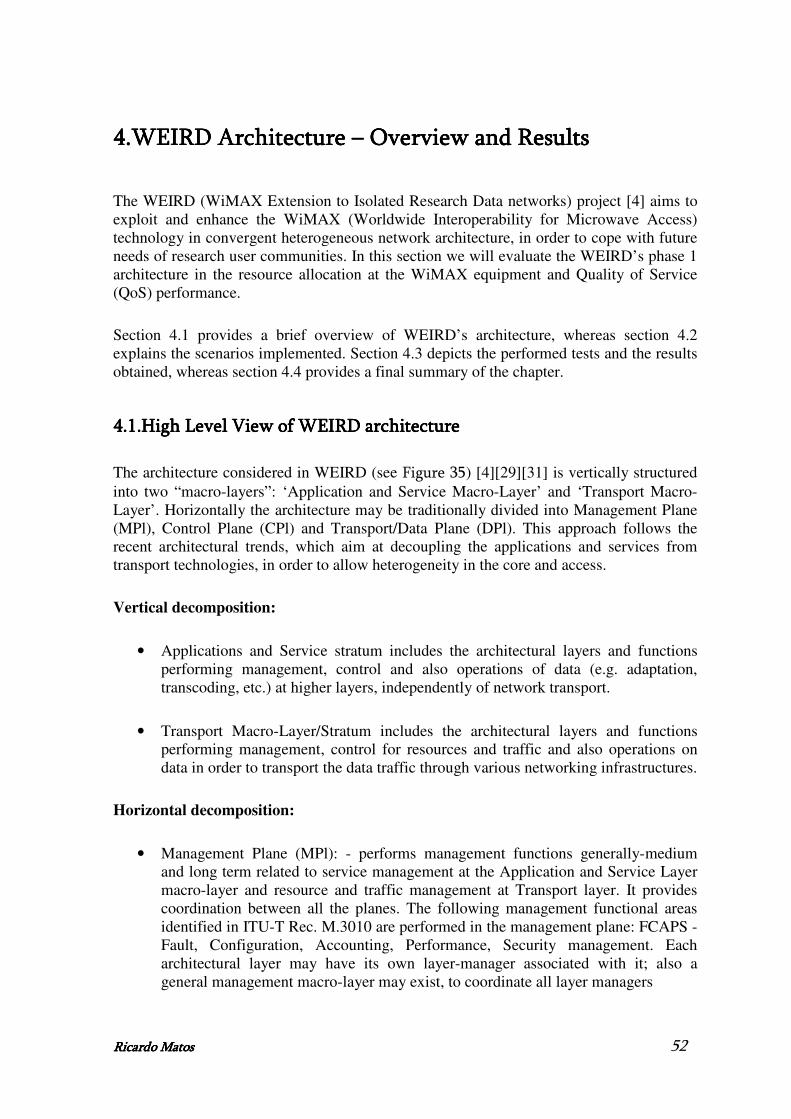
Ricardo MatoRicardo MatoRicardo MatoRicardo Matossss 52
4.4.4.4.WEIRD Architecture WEIRD Architecture WEIRD Architecture WEIRD Architecture –––– Overview and Results Overview and Results Overview and Results Overview and Results
The WEIRD (WiMAX Extension to Isolated Research Data networks) project [4] aims to exploit and enhance the WiMAX (Worldwide Interoperability for Microwave Access) technology in convergent heterogeneous network architecture, in order to cope with future needs of research user communities. In this section we will evaluate the WEIRD’s phase 1 architecture in the resource allocation at the WiMAX equipment and Quality of Service (QoS) performance.
Section 4.1 provides a brief overview of WEIRD’s architecture, whereas section 4.2 explains the scenarios implemented. Section 4.3 depicts the performed tests and the results obtained, whereas section 4.4 provides a final summary of the chapter.
4.1.4.1.4.1.4.1.High Level View of High Level View of High Level View of High Level View of WEIRD archiWEIRD archiWEIRD archiWEIRD architecturetecturetecturetecture
The architecture considered in WEIRD (see Figure 35) [4][29][31] is vertically structured into two “macro-layers”: ‘Application and Service Macro-Layer’ and ‘Transport Macro-Layer’. Horizontally the architecture may be traditionally divided into Management Plane (MPl), Control Plane (CPl) and Transport/Data Plane (DPl). This approach follows the recent architectural trends, which aim at decoupling the applications and services from transport technologies, in order to allow heterogeneity in the core and access.
Vertical decomposition:
• Applications and Service stratum includes the architectural layers and functions performing management, control and also operations of data (e.g. adaptation, transcoding, etc.) at higher layers, independently of network transport.
• Transport Macro-Layer/Stratum includes the architectural layers and functions performing management, control for resources and traffic and also operations on data in order to transport the data traffic through various networking infrastructures.
Horizontal decomposition:
• Management Plane (MPl): - performs management functions generally-medium and long term related to service management at the Application and Service Layer macro-layer and resource and traffic management at Transport layer. It provides coordination between all the planes. The following management functional areas identified in ITU-T Rec. M.3010 are performed in the management plane: FCAPS - Fault, Configuration, Accounting, Performance, Security management. Each architectural layer may have its own layer-manager associated with it; also a general management macro-layer may exist, to coordinate all layer managers

Ricardo MatoRicardo MatoRicardo MatoRicardo Matossss 53
• Control Plane (CPl) includes all layers which perform short term control actions related to higher layers (high level services and applications): through signalling, the control plane sets up and releases high level connections, and may restore a connection in case of a failure; transport layers: CPl performs the short term actions for resource and traffic engineering and control, including routing.
• Data Plane (DPl) (also called Transport Plane) is mainly responsible for transferring the user/application data. In case of IP architectures the data plane also transports (via unique IP) the control and management related data between the respective entities. The DPl may include functions and mechanisms to act upon the packets transported. In multi-domain environment the transport stratum may be split in inter and intra-domain parts.
FigurFigurFigurFigure e e e 35353535 ---- General architectural planes in a multi-domain environment [4]
The WEIRD system is layered according to the architecture model described above. The applications are running on the client endpoints and are located in the highest layer of the model. The WEIRD application and service stratum contains a signalling control channel to let applications to ask for services. This control channel lets applications to request QoS in the local AS (including WiMAX channel).

Ricardo MatoRicardo MatoRicardo MatoRicardo Matossss 54
The application service control plane is located in – Application and Service Stratum – providing session and service control to the applications. It communicates upward with applications, either by APIs or application signalling protocol(s), like SIP (Session Initiation Protocol), RTSP (Real Time Streaming Protocol), etc.... It communicates downwards with the WEIRD control plane, which provides Resource and Control functions, by control signalling.
The WEIRD resource control plane is located in the lower vertical macro-layer – Transport Stratum and performs typically transport of data and resource control.
4.1.1.4.1.1.4.1.1.4.1.1.Control PControl PControl PControl Planelanelanelane
WEIRD’s architecture considers the functional entities as Mobile Station (MS), Access Service Network (ASN) and Connectivity Service Network (CSN), based on WiMAX Forum [40] [42].
Attempting at the resource allocation in WiMAX link promoted by WEIRD architecture, there are many modules that have different responsibilities at the all process, which endorse a lot of signalling between them as depicted in Figure 36 [36][37].
Figure Figure Figure Figure 36363636 ---- WEIRD WEIRD WEIRD WEIRD’s’s’s’s Phase 1 Architecture Phase 1 Architecture Phase 1 Architecture Phase 1 Architecture –––– Control Plane Control Plane Control Plane Control Plane
• CSC_MS (Connectivity Service Controller located at Mobile Station) can be both initiator (for legacy applications triggered by WEIRD Agent or by a WEIRD aware application) and responder (for SIP applications [22] where the destination is the Mobile Node) of resource reservations in the WiMAX link and the management of QoS signalling.
• CSC_ASN is the main coordination point for the resource reservation in the WiMAX link and the management of the related QoS signalling; the role of the

Ricardo MatoRicardo MatoRicardo MatoRicardo Matossss 55
CSC_ASN and its communication with other modules depends on the type of the managed application: Legacy and WEIRD aware applications or SIP applications. CSC_ASN is the coordination point of the ASN-GW and it receives requests from the NSIS (Next Step in Signaling) module, interacts with AAA (Authentication, Authorization and Accounting) server for user authorization, performs Admission Control, and sends requests to the Resource Control for Servive Flow (SF) creation/deletion.
• CSC_CSN is the controller of Connectivity Service Network, communicating with the rest of the architecture through NSIS.
• NSIS is a signalling protocol for QoS reservations and allows the communication between all CSCs [13].
• Resource Controller (RC) is responsible for managing the WIMAX network(s), as well the interface with the upper layers. It has the capability to differentiate among 802.16d and 802.16e requests and trigger the correspondent interface with the appropriate Adapter module.
• Generic Adapter (GA) is the module that provides an abstracted interface for the interactions between the upper modules and the vendor Base Station (BS).
• Redline Specific Adapter (RSA) is responsible to enforce the RC decisions on the WiMAX BS.
• AAA [21] is the module that is in charge to perform user authentication, QoS authorization and session accounting communicating with CSC_ASN through Diameter [23] signalling.
• WEIRD Agent allows a user to trigger the resource request reservation by specifying the QoS requirements of an application.
• SIP Proxy is the software module supporting SIP application signalling. It performs authentication and resource reservation on behalf of SIP users.
• NMS (Network Management System) is the centralized management system in the ASN that provides a single interface to manage and monitor the network elements in the WiMAX and ASN access network.
4.2.4.2.4.2.4.2.Legacy Scenarios ImplementedLegacy Scenarios ImplementedLegacy Scenarios ImplementedLegacy Scenarios Implemented
At this section will be explained the scenarios implemented to obtain values for WEIRD’s phase 1 signalling in resource allocation and to study the QoS attribution by WEIRD’s architecture.
Figure 37 and Figure 38 demonstrates the scenarios implemented. As we can see, both of scenarios have three different parts: MS where exists the Mobile Terminal and the Subscriber Station, which communicate via WIMAX with Base Station located in ASN.
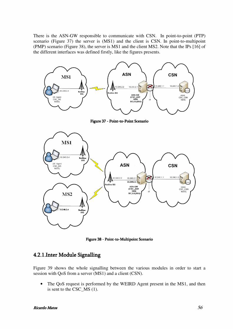
Ricardo MatoRicardo MatoRicardo MatoRicardo Matossss 56
There is the ASN-GW responsible to communicate with CSN. In point-to-point (PTP) scenario (Figure 37) the server is (MS1) and the client is CSN. In point-to-multipoint (PMP) scenario (Figure 38), the server is MS1 and the client MS2. Note that the IPs [16] of the different interfaces was defined firstly, like the figures presents.
Figure Figure Figure Figure 37373737 ---- Point Point Point Point----totototo----Point ScenarioPoint ScenarioPoint ScenarioPoint Scenario
Figure Figure Figure Figure 38383838 ---- PointPointPointPoint----totototo----MMMMultipoint Scenarioultipoint Scenarioultipoint Scenarioultipoint Scenario
4.2.1.4.2.1.4.2.1.4.2.1.Inter Module SignallingInter Module SignallingInter Module SignallingInter Module Signalling
Figure 39 shows the whole signalling between the various modules in order to start a session with QoS from a server (MS1) and a client (CSN).
• The QoS request is performed by the WEIRD Agent present in the MS1, and then is sent to the CSC_MS (1).

Ricardo MatoRicardo MatoRicardo MatoRicardo Matossss 57
• Then through NSIS signalling the request reaches the ASN (more properly the module CSC_ASN) (2-4).
• Afterwards the request is sent by Diameter signalling to the AAA present in the CSN to be logged (5-6).
• Returned to the ASN, the request will be made on the WiMAX equipment (uplink service flow associated with SS1). For this the CSC_ASN communicates with the RC which subsequently sends the request to the Generic Adapter and the Redline Specific Adapter [38] (7-9).
• Done the request at the equipment, the response returns to the CSC_ASN (10-12).
• As the client is on the CSN side, it will have to be made a reserve of QoS on CSN side, and so the request goes there through NSIS signalling (13-15).
• Arrived the response at ASN (16-17), the answer returns to MS1 (CSC_MS) through NSIS signalling (18-19).
• Finally the reply is forwarded to the WEIRD Agent (20).
Figure Figure Figure Figure 39393939 ---- PTP Inter PTP Inter PTP Inter PTP Inter----module Signallingmodule Signallingmodule Signallingmodule Signalling
Figure 40 shows the whole signalling between the various modules in order to start a session with QoS from a server (MS1) and a client (MS2).
• The QoS request is performed by the Agent WEIRD present in the MS1, and then is sent to the CSC_MS (1).

Ricardo MatoRicardo MatoRicardo MatoRicardo Matossss 58
• Then through NSIS signalling the request reaches the ASN (more properly the module CSC_ASN) (2-4).
• Afterwards the request is sent by Diameter signalling to the AAA present in the CSN to be logged (5-6).
• Returned to the ASN, the request will be made on the WiMAX equipment (uplink service flow associated with SS1). For this the CSC_ASN communicates with the RC which subsequently sends the request to the Generic Adapter and the Redline Specific Adapter [38] (7-9).
• Done the request at the equipment, the response returns to the CSC_ASN (10-12).
• As the client is on the SS2 side, it will have to be made a new reserve at the equipment (downlink service flow associated with SS2) (13-18).
• Done the second request and arrived the response at CSC_ASN, the answer returns to MS1 (CSC_MS) through NSIS signalling (19-21).
• Finally the reply is forwarded to the WEIRD Agent (22).
Figure Figure Figure Figure 40404040 ---- PMP Inter PMP Inter PMP Inter PMP Inter----module Signallingmodule Signallingmodule Signallingmodule Signalling

Ricardo MatoRicardo MatoRicardo MatoRicardo Matossss 59
4.3.4.3.4.3.4.3.Performed testsPerformed testsPerformed testsPerformed tests
4.3.1.4.3.1.4.3.1.4.3.1.Processing times for signallingProcessing times for signallingProcessing times for signallingProcessing times for signalling
After establishing the scenarios, it was time to measure the processing times of the various modules needed to make a reservation of QoS using WEIRD’s phase 1 architecture.
For that we sent all the logs produced by the different modules to different files (to optimize the processing times). Another of the changes we made in the various modules was slightly change the code in order to know when messages were sent or arrived them, using the time functions provided by the languages that were used to develop the software. We made 10 followed reservations in the equipment (for each scenario).
Before we start the request in WA we have defined at the RedMAX Equipment a set of service flows in which the traffic will pass. We inserted at BS-SS1 WiMAX link two services flows based on MAC of the PC on the SS1 domain: one uplink and other downlink. We did the same at BS-SS2 WiMAX link but now based on MAC of the PC located in SS2 domain. With these four service flows all the signalling of the architecture will pass through WiMAX links.
We are also interested to obtain the processing times for signalling when there is some application traffic filling the WiMAX links. For this we add some VoIP traffic between the MS (located in SS side) and ASN (located in BS side) and perform some requests while that traffic is passing the WiMAX link. The VoIP traffic was generated like depicted in section 3.4.1.2 for VoIP (without aggregation) case. We started measuring the signalling time without traffic from application, then with 100 VoIP flows flowing through WiMAX (both uplink and downlink), then we increased it for 200, 300 and finally to 400.
4.3.1.1.4.3.1.1.4.3.1.1.4.3.1.1.PointPointPointPoint----totototo----Point SPoint SPoint SPoint Scenariocenariocenariocenario
This section provides all the measures withdrawn from the WEIRD’s phase 1 signalling for point-to-point scenario.
Figure 41 shows us that when the WiMAX channel begins to be occupied by traffic of a particular application (in this case VoIP), the percentage of successful requests made by Weird Agent begins to decline.

Ricardo MatoRicardo MatoRicardo MatoRicardo Matossss 60
0
20
40
60
80
100
120
0 100 200 300 400
Number of VoIP Flows
Su
ccessfu
l R
eq
uests
(%
)
FiFiFiFigure gure gure gure 41414141 ---- Percentage of Successful Requests Percentage of Successful Requests Percentage of Successful Requests Percentage of Successful Requests
Figure 42 shows us that when the VoIP traffic begins to increase and saturate the capacity of the WiMAX channel, NSIS signalling, which is performed through WiMAX, greatly increases its processing time, due particularly of the congestion of the WiMAX channel. In this situation if time is too high the NSIS generates a time-out and the requests are not routed to the ASN. Because of this behaviour some requests were not successful at the equipment.
0 100 200 3000
0.5
1
1.5
2
2.5
3
x 104
NS
IS (
ms)
Number of VoIP flows
Figure Figure Figure Figure 42424242 ---- Processing time by NSIS (MS<Processing time by NSIS (MS<Processing time by NSIS (MS<Processing time by NSIS (MS<---->ASN)>ASN)>ASN)>ASN)
Figure 43 and Figure 44 shows us the processing times for Diameter signalling (between CSC_ASN and AAA) and for the communication with the equipment to perform the request of the service flow, respectively. It demonstrates that these two times are approximately constant, even increasing the VoIP flows through WiMAX.

Ricardo MatoRicardo MatoRicardo MatoRicardo Matossss 61
0 100 200 3000
20
40
60
80
100
120
140
160
Dia
mete
r sig
nalli
ng (
ms)
Number of VoIP flows
Figure Figure Figure Figure 43434343 ---- Diameter SignallingDiameter SignallingDiameter SignallingDiameter Signalling
0 100 200 3007
8
9
10
11
12
13
14
15
16
17
18
WiM
AX
Cro
ss L
ayer
(ms)
Number of VoIP flows
Figure Figure Figure Figure 44444444 ---- Processing time between CSC_ASN and the Equipment Processing time between CSC_ASN and the Equipment Processing time between CSC_ASN and the Equipment Processing time between CSC_ASN and the Equipment
As we can see in Figure 45 the CSCs processing time increases slowly between the different experiments. This demonstrates that its processing is affected by the delay of the signalling between the MS and ASN due of the increasing congestion of the WiMAX channel.
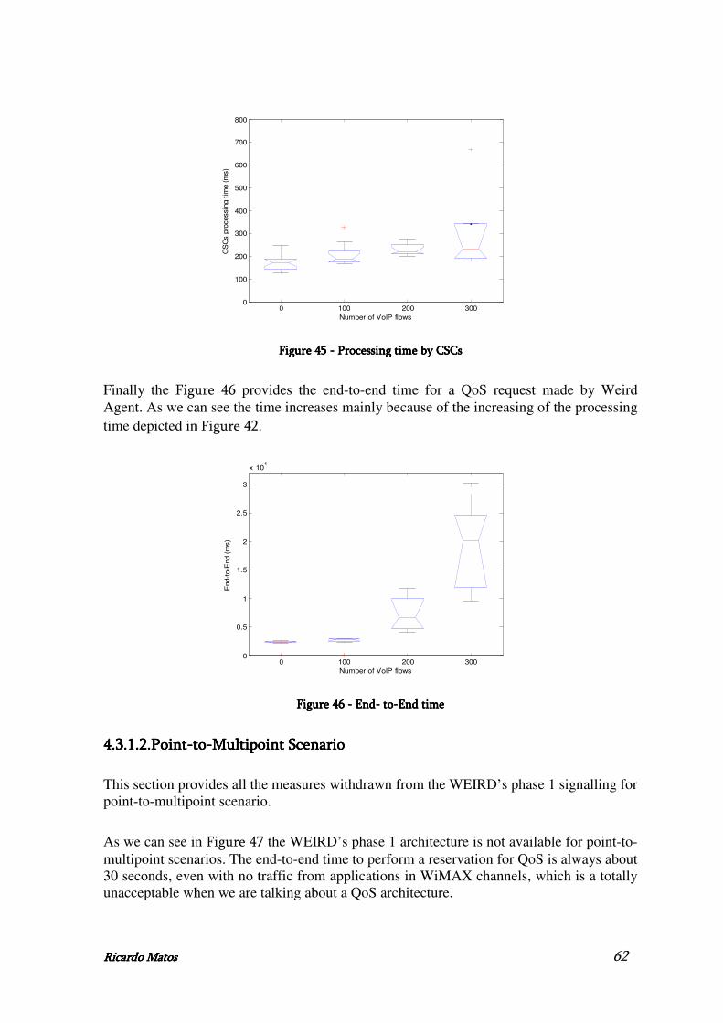
Ricardo MatoRicardo MatoRicardo MatoRicardo Matossss 62
0 100 200 3000
100
200
300
400
500
600
700
800
CS
Cs p
rocessin
g t
ime (
ms)
Number of VoIP flows
Figure Figure Figure Figure 45454545 ---- P P P Processing time by CSCrocessing time by CSCrocessing time by CSCrocessing time by CSCssss
Finally the Figure 46 provides the end-to-end time for a QoS request made by Weird Agent. As we can see the time increases mainly because of the increasing of the processing time depicted in Figure 42.
0 100 200 3000
0.5
1
1.5
2
2.5
3
x 104
End-t
o-E
nd (
ms)
Number of VoIP flows
Figure Figure Figure Figure 46464646 ---- End End End End---- to to to to----EEEEnd time nd time nd time nd time
4.3.1.2.4.3.1.2.4.3.1.2.4.3.1.2.PointPointPointPoint----totototo----Multipoint SMultipoint SMultipoint SMultipoint Scenariocenariocenariocenario
This section provides all the measures withdrawn from the WEIRD’s phase 1 signalling for point-to-multipoint scenario.
As we can see in Figure 47 the WEIRD’s phase 1 architecture is not available for point-to-multipoint scenarios. The end-to-end time to perform a reservation for QoS is always about 30 seconds, even with no traffic from applications in WiMAX channels, which is a totally unacceptable when we are talking about a QoS architecture.

Ricardo MatoRicardo MatoRicardo MatoRicardo Matossss 63
0 100 200 3002.5
2.6
2.7
2.8
2.9
3
3.1
3.2
3.3
3.4
3.5x 10
4
End-t
o-E
nd (
ms)
Number of VoIP flows
Figure Figure Figure Figure 47474747 ---- EndEndEndEnd---- t t t toooo----EEEEnd timend timend timend time
Note that in this situation the processing time for AAA is basically the same as before and the processing time of CSCs is lower than before because the request doesn’t have to go through NSIS signalling to CSC_CSN, as the client is on the SS2 side. Because of this, it will be made two reservations at the equipment: the first at SS1 and the second at SS2.
4.3.2.4.3.2.4.3.2.4.3.2.QoS TestsQoS TestsQoS TestsQoS Tests
After analysing the signalling process we will be now study the QoS provided by WEIRD architecture. With the scenario depicted in Figure 37 we will firstly analyse the uplink channel, doing a reservation in Weird Agent from the source (MS) to the sink (CSN) and compare the results with the ones described in section 3.4.2.1 (VoIP without aggregation) without the WEIRD software. After this, we will do the same but now to study the downlink channel (source of traffic is CSN and the sink the MS). Note that, after the service flow is made on the equipment we want to see if the traffic generated with the JTG (see section 3.4.1.2) passes through the service flow made in equipment by WEIRD software, and its influence on QoS.
In Figure 48, Figure 49 and Figure 50 are described the results for uplink channel.
We saw that VoIP generated traffic by JTG passes through the “WEIRD’s service flow” and not by default service flows generated before starting WEIRD’s software (it is true not only for uplink channel but also for downlink channel).
The results give us the perception that one of the main objectives of the WEIRD’s architecture was completed, we mean, WEIRD tries to be an architecture that controls the traffic that passes by the WiMAX equipment, giving more priority or not to a particular type of traffic as it is required or not, thus allowing the proper allocation of resources at equipment.
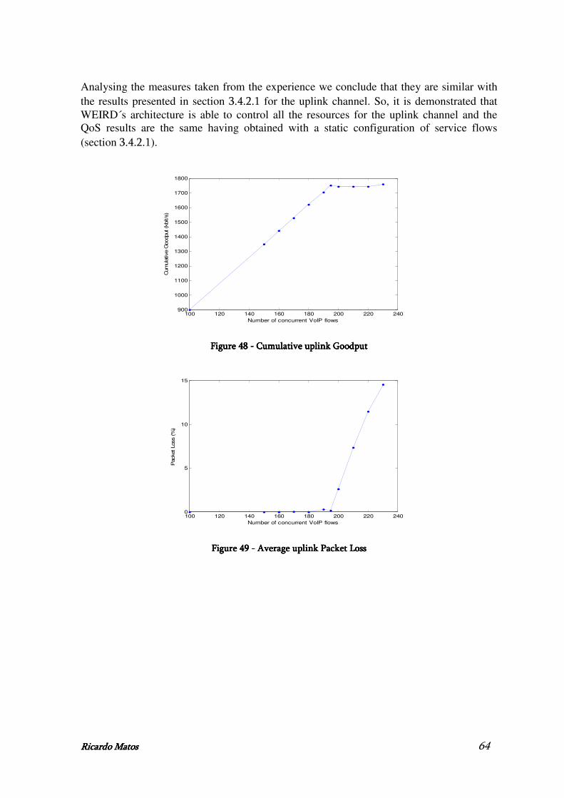
Ricardo MatoRicardo MatoRicardo MatoRicardo Matossss 64
Analysing the measures taken from the experience we conclude that they are similar with the results presented in section 3.4.2.1 for the uplink channel. So, it is demonstrated that WEIRD´s architecture is able to control all the resources for the uplink channel and the QoS results are the same having obtained with a static configuration of service flows (section 3.4.2.1).
100 120 140 160 180 200 220 240900
1000
1100
1200
1300
1400
1500
1600
1700
1800
Number of concurrent VoIP flows
Cum
ula
tive G
oodput (k
bit/s
)
Figure Figure Figure Figure 48484848 ---- Cumulative uCumulative uCumulative uCumulative uplink Gplink Gplink Gplink Goodputoodputoodputoodput
100 120 140 160 180 200 220 2400
5
10
15
Number of concurrent VoIP flows
Packet Loss (%
)
Figure Figure Figure Figure 49494949 ---- Average u Average u Average u Average uplink Packet Lplink Packet Lplink Packet Lplink Packet Lossossossoss
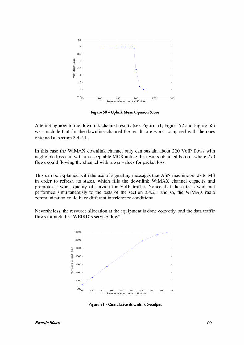
Ricardo MatoRicardo MatoRicardo MatoRicardo Matossss 65
50 100 150 200 250 3000.5
1
1.5
2
2.5
3
3.5
4
4.5
Number of concurrent VoIP flows
Mean O
pin
ion S
core
Figure Figure Figure Figure 50505050 ---- Uplink MUplink MUplink MUplink Mean ean ean ean OOOOpinion pinion pinion pinion SSSScorecorecorecore
Attempting now to the downlink channel results (see Figure 51, Figure 52 and Figure 53) we conclude that for the downlink channel the results are worst compared with the ones obtained at section 3.4.2.1.
In this case the WiMAX downlink channel only can sustain about 220 VoIP flows with negligible loss and with an acceptable MOS unlike the results obtained before, where 270 flows could flowing the channel with lower values for packet loss.
This can be explained with the use of signalling messages that ASN machine sends to MS in order to refresh its states, which fills the downlink WiMAX channel capacity and promotes a worst quality of service for VoIP traffic. Notice that these tests were not performed simultaneously to the tests of the section 3.4.2.1 and so, the WiMAX radio communication could have different interference conditions.
Nevertheless, the resource allocation at the equipment is done correctly, and the data traffic flows through the “WEIRD’s service flow”.
100 120 140 160 180 200 220 240 260 280800
1000
1200
1400
1600
1800
2000
2200
Number of concurrent VoIP flows
Cum
ula
tive G
oodput (k
bit/s
)
Figure Figure Figure Figure 51515151 ---- Cumulati Cumulati Cumulati Cumulative downlink Gve downlink Gve downlink Gve downlink Goodput oodput oodput oodput

Ricardo MatoRicardo MatoRicardo MatoRicardo Matossss 66
100 120 140 160 180 200 220 240 260 2800
1
2
3
4
5
6
7
8
9
10
Number of concurrent VoIP flows
Packet Loss (%
)
Figure Figure Figure Figure 52525252 ---- Average downlink Packet L Average downlink Packet L Average downlink Packet L Average downlink Packet Lossossossoss
50 100 150 200 250 3000.5
1
1.5
2
2.5
3
3.5
4
4.5
Number of concurrent VoIP flows
Mean O
pin
ion S
core
Figure Figure Figure Figure 53535353 ---- Downlink M Downlink M Downlink M Downlink Mean ean ean ean OOOOpinion pinion pinion pinion SSSScorecorecorecore
4.4.4.4.4.4.4.4.SummarySummarySummarySummary
At this chapter, unlike the point-to-point scenario, which give us acceptable values for the signalling in the resource allocation at the WiMAX equipment, the point-to-multipoint scenario doesn’t work in the correct manner in the WEIRD project.
Finally, with the results of the section 4.3.2 we conclude that the QoS specification done by the WEIRD’s software, for a specific application, is established correctly at the equipment.

Ricardo MatoRicardo MatoRicardo MatoRicardo Matossss 67
5.5.5.5.Mobility Architecture and DevelopmentMobility Architecture and DevelopmentMobility Architecture and DevelopmentMobility Architecture and Development
The ability to connect and trasmit voice, video and data connections anywhere and anytime is a compelling vision for consumers and a main goal for near future. In order to obtain this, IEEE 802.21 Media Independent Handover (MIH) standard [3] provides link layer intelligence and other related network information to upper layers to optimize handovers (HOs) between heterogeneous media providing the seamless handover between networks of the same (HO Horizontal) or different technologies (HO Vertical), being independent of the physical networks.
This chapter presents the WEIRD’s (WiMAX Extension to Isolated Research Data networks) mobility architecture in which the developed work is inserted, which aims to demonstrate the correct integration between IEEE 802.21 architecture through WiMAX (Worldwide Interoperability for Microwave Access) segments. MIHF is a module of this architecture and its implementation will be described at this chapter.
In section 5.1 we present the overview of the architecture in its all, presenting the main objectives and differences between the phase 2 and phase 1 of WEIRD’s architecture. Section 5.2 presents the mobility architecture and its modules. Section 5.3 presents the MIHF (Media Independent Handover Function) implementation including the specification, implementation and its configuration, whereas section 5.4 provides the specification of the messages exchanged between MIHF and the rest of the architecture. Finally section 5.5 provides a final summary of the chapter.
5.1.5.1.5.1.5.1.WEIRD architecture with mobilityWEIRD architecture with mobilityWEIRD architecture with mobilityWEIRD architecture with mobility
5.1.1.5.1.1.5.1.1.5.1.1.ObjectivesObjectivesObjectivesObjectives
The WEIRD project was implemented in two phases: phase 1 where most modules were developed with basic functionality, in order to perform more tests with applications such as Video, VoIP (Voice over IP), Telemedicine, Fire Prevention [30][32][33], and phase 2 where new modules and advanced features, like the implementation of a mobility scenario including MIP and MIH over WiMAX, were added to the software developed for phase1.
5.1.2.5.1.2.5.1.2.5.1.2.OverwiewOverwiewOverwiewOverwiew
WEIRD’s phase 2 [5] software components are illustrated in Figure 54. Besides the modules developed for phase 1 [4], it also shows the new modules developed for phase 2. The new modules developed for phase 2 were: MIHU - Media Independent Handover User, MIHF - Media Independent Handover Function, NSIS Mobility NSLP (NSIS Signaling Layer Protocol), LLC - Lower Layer Controller, Mobility GUI and Mobility Manager (MM). The other ones were enhanced in order to perform Quality of Service (QoS) session setup and reservations both with legacy and SIP (Session Initiation Protocol) scenarios.
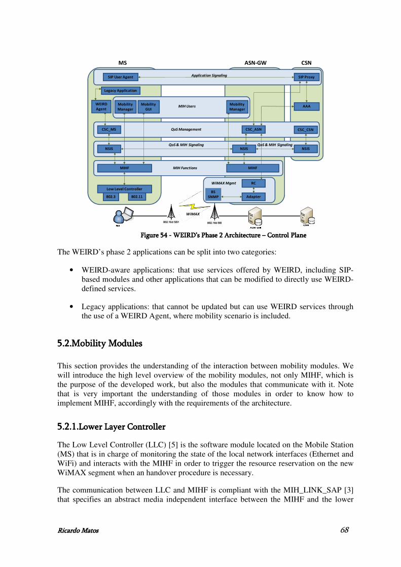
Ricardo MatoRicardo MatoRicardo MatoRicardo Matossss 68
CSC_ASN
BS
SNMP
MS
Application Signaling
QoS & MIH Signaling
Low Level Controller
CSC_MS CSC_CSN
NSIS
Legacy Application
SIP User Agent SIP Proxy
WEIRD
Agent
Mobility
Manager
MIHF
QoS Management
MIH Users
MIH Functions MIHF
NSISNSIS
AAAMobility
Manager
Mobility
GUI
QoS & MIH Signaling
802.3 802.11 Adapter
RC
WiMAX
ASN-GW CSN
WiMAX Mgmt
Figure Figure Figure Figure 54545454 ---- WEIRD WEIRD WEIRD WEIRD’s’s’s’s Phase 2 Architecture Phase 2 Architecture Phase 2 Architecture Phase 2 Architecture –––– Control Plane Control Plane Control Plane Control Plane
The WEIRD’s phase 2 applications can be split into two categories:
• WEIRD-aware applications: that use services offered by WEIRD, including SIP-based modules and other applications that can be modified to directly use WEIRD-defined services.
• Legacy applications: that cannot be updated but can use WEIRD services through the use of a WEIRD Agent, where mobility scenario is included.
5.2.5.2.5.2.5.2.Mobility ModulesMobility ModulesMobility ModulesMobility Modules
This section provides the understanding of the interaction between mobility modules. We will introduce the high level overview of the mobility modules, not only MIHF, which is the purpose of the developed work, but also the modules that communicate with it. Note that is very important the understanding of those modules in order to know how to implement MIHF, accordingly with the requirements of the architecture.
5.2.1.5.2.1.5.2.1.5.2.1.Lower Layer ControllerLower Layer ControllerLower Layer ControllerLower Layer Controller
The Low Level Controller (LLC) [5] is the software module located on the Mobile Station (MS) that is in charge of monitoring the state of the local network interfaces (Ethernet and WiFi) and interacts with the MIHF in order to trigger the resource reservation on the new WiMAX segment when an handover procedure is necessary.
The communication between LLC and MIHF is compliant with the MIH_LINK_SAP [3] that specifies an abstract media independent interface between the MIHF and the lower

Ricardo MatoRicardo MatoRicardo MatoRicardo Matossss 69
layers media-specific protocol stacks such as IEEE 802.3 (Ethernet) and IEEE 802.11 (WiFi).
The primitives exchanged between LLC and MIHF are:
• Link_Up – This event is sent by the LLC to notify that a layer 2 interface (Ethernet or WiFi) is configured and ready to be used.
• Link_Going_Down – This event is sent by the LLC to notify that a layer 2 connection (Ethernet) is expected to go down. It is used to trigger the resource reservation procedure on the new WiMAX channel.
• Link_Down – This event is sent by the LLC to notify that a layer 2 connection (Ethernet or WiFi) is broken. It is used to trigger the handover process and delete the QoS reservation on the old WiMAX segment.
• Link_Action – This request is sent by the MIHF to perform an action on a pre-defined link layer connection. It used by the LLC to notify the user that the resource reservation on the new WiMAX channel has been completed successfully.
The detailed description of the messages sent by this module is described on chapter 11.
The LLC is endowed with a GUI that allows the user of the MS to know the networks connectivity state (Figure 55). When the state of a network interface changes, the colour in the circle depicted in the GUI varies and a new message appears in the text area to notify the user of the event. Therefore he can evaluate the situation and take a decision. For example if both the Ethernet and WiFi interfaces are ready to be used, he can trigger the Link_Going_Down event by pushing the button on the GUI.
Figure Figure Figure Figure 55555555 ---- LLC Graphical User Interface LLC Graphical User Interface LLC Graphical User Interface LLC Graphical User Interface
Moreover the GUI is also employed to allow the user to know the result of the resource reservation procedure on the new WiMAX channel. An internal timer is started when the LLC sends the Link_Going_Down event to the MIHF. If the Link Action is received before the timeout, the QoS reservation is considered successfully completed and a message is shown on the GUI. Otherwise the QoS reservation is failed.
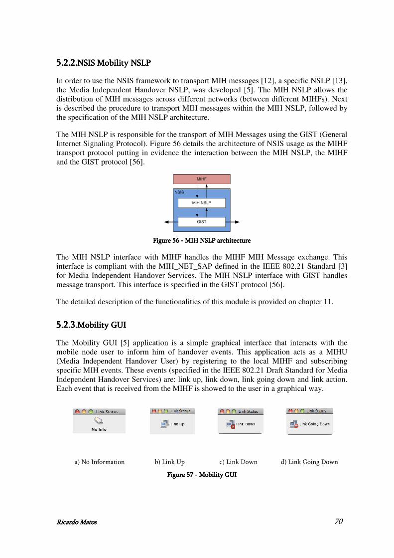
Ricardo MatoRicardo MatoRicardo MatoRicardo Matossss 70
5.2.2.5.2.2.5.2.2.5.2.2.NSIS Mobility NSLPNSIS Mobility NSLPNSIS Mobility NSLPNSIS Mobility NSLP
In order to use the NSIS framework to transport MIH messages [12], a specific NSLP [13], the Media Independent Handover NSLP, was developed [5]. The MIH NSLP allows the distribution of MIH messages across different networks (between different MIHFs). Next is described the procedure to transport MIH messages within the MIH NSLP, followed by the specification of the MIH NSLP architecture.
The MIH NSLP is responsible for the transport of MIH Messages using the GIST (General Internet Signaling Protocol). Figure 56 details the architecture of NSIS usage as the MIHF transport protocol putting in evidence the interaction between the MIH NSLP, the MIHF and the GIST protocol [56].
Figure Figure Figure Figure 56565656 ---- MIH NSLP architecture MIH NSLP architecture MIH NSLP architecture MIH NSLP architecture
The MIH NSLP interface with MIHF handles the MIHF MIH Message exchange. This interface is compliant with the MIH_NET_SAP defined in the IEEE 802.21 Standard [3] for Media Independent Handover Services. The MIH NSLP interface with GIST handles message transport. This interface is specified in the GIST protocol [56].
The detailed description of the functionalities of this module is provided on chapter 11.
5.2.3.5.2.3.5.2.3.5.2.3.Mobility GUIMobility GUIMobility GUIMobility GUI
The Mobility GUI [5] application is a simple graphical interface that interacts with the mobile node user to inform him of handover events. This application acts as a MIHU (Media Independent Handover User) by registering to the local MIHF and subscribing specific MIH events. These events (specified in the IEEE 802.21 Draft Standard for Media Independent Handover Services) are: link up, link down, link going down and link action. Each event that is received from the MIHF is showed to the user in a graphical way.
a) No Information b) Link Up c) Link Down d) Link Going Down
Figure Figure Figure Figure 57575757 ---- Mobility GUI Mobility GUI Mobility GUI Mobility GUI

Ricardo MatoRicardo MatoRicardo MatoRicardo Matossss 71
In Figure 57 a) the Mobility GUI shows its default state, that no information could be read and presented to the user. In Figure 57 b) the Mobility GUI displays the information that the Link is up. In Figure 57 c) the Mobility GUI displays the information that the Link is down. In Figure 57 d) the Mobility GUI displays the information that the Link is going down.
5.2.4.5.2.4.5.2.4.5.2.4.CSC_MSCSC_MSCSC_MSCSC_MS
The management of all the control plane functionalities related to the resource update for mobility is performed at the CSC (Connectivity Service Controller), through a new specific module called Mobility Manager (MM) [5]. This module acts as a MIHU interacting with the MIHF module in order to exchange IEEE 802.21 MIH Services.
The main functionalities of the CSC_MS MM are the following: management of the MIH messages received from the MIHF and update of its internal status; management of the new resource reservation between the target Subscriber Station (SS) and the Base Station (BS) when the MN moves between different SSs; management of the release of the old resources between the serving SS and the BS.
The CSC Mobility Manager manages all the information about the network interfaces of the host and inspects the retrieved MIH messages in order to update their status. If an incumbent change of the active network interface is detected, the CSC Mobility Manager interacts with the CSC Engine [5] in order to prepare the handover following a Make-Before-Break approach.
When the MM receives a MIHF Link_Going_Down message that indicates an imminent handover, it initiates the NSIS signaling in order to create new SFs (between the target SS and the target BS) for the data traffic of the existing application sessions. If the reservation result is successful, the MM sends a MIHF Link_Action message to the MIHF so that the handover procedure can proceed. The end of the handover process and the availability of the new L3 connection is signaled by the MIHF Link_Down message: when this type of message is received, the NSIS signaling is triggered again in order to delete the old SFs between the BS and the serving SS.
Figure 58 shows the architecture of the CSC_MS, underlining the strict interaction between the CSC Mobility Manager and the CSC engine that manages the NSIS QoS signaling sessions for the active applications. The interaction between the CSC_MS MM and the MIHF module uses the MIHF Attendant. This entity handles the connection between the MIHF and the CSC_MS, is in charge of the MIHU initialization and performs a first parsing of the IEEE 802.21 messages. Messages received from the MIHF are first processed by the MIHF Attendant and then forwarded to the CSC Mobility Manager through the MM Queue. Messages from the CSC Mobility Manager are sent to the external MIHF module using the API of the MIHF Attendant.

Ricardo MatoRicardo MatoRicardo MatoRicardo Matossss 72
Figure Figure Figure Figure 58585858 ---- CSC_MS architecture CSC_MS architecture CSC_MS architecture CSC_MS architecture
The architecture of the CSC_MS Mobility Manager and its interaction with the external modules is shown in Figure 59.
Figure Figure Figure Figure 59595959 ---- CSC_MS CSC_MS CSC_MS CSC_MS Mobility Manager Mobility Manager Mobility Manager Mobility Manager architecturearchitecturearchitecturearchitecture
Messages from the MIHF module are retrieved from the MM Input Queue of the MIHF Attendant by the MIHF Thread. For each received MIHF message, the Node Manager updates its internal status. In particular, the Node Manager handles all the information related to the network interfaces of the host (Table 7).
Network Interfaces Information
Network Interface ID Network Interface Type Eth/WiFi MAC Address IP Address Priority Status Up/Going-Down/Down Active True / False With traffic True / False
Table Table Table Table 7777 ---- Network Interfaces Information handled by the node managerNetwork Interfaces Information handled by the node managerNetwork Interfaces Information handled by the node managerNetwork Interfaces Information handled by the node manager
The priority value is used to decide which interface is active when more network interfaces are in the status Up. In this case, the active interface is the one with the lower value of priority. The interface “with traffic” is the one that is currently used for the data traffic.
The Main Thread handles all the procedures related to the handover. When new handover actions must be performed, according to the received MIHF message and the current Node Manager status, the MIHF Thread triggers the Main Thread that controls all the handover phases. In particular, the handover procedure consists of two different phases: the HO MAKE, when new SFs are allocated between the target SS and BS, and the HO BREAK, when old SFs between serving SS and BS are deleted.

Ricardo MatoRicardo MatoRicardo MatoRicardo Matossss 73
The HO MAKE Phase Involves all the existing active sessions for legacy applications. In order to retrieve all the required information about them, the Main Thread interacts with the CSC_MS engine, in particular with its Session Manager. Information about existing sessions are stored in the Mobility Session Manager, used to handle the status of all the application sessions and the associated NSIS sessions for mobility during the handover process, checking the resource reservation result for each of them.
The Main Thread also interacts with the CSC_MS engine in order to initiate the NSIS signalling for the reservation and the activation of the WiMAX SF to be used after the HO. The QSPEC carried with the NSIS messages includes the following values: Application Type (MOBILITY), QoS parameters (as defined in the WiMAX QoS model), Classifier (IP addresses and ports, ToS, protocol), Mobility Command (Make, Break), Application NSIS Session ID.
The mobility command specifies the type of operation to be performed, while the application NSIS session ID specifies which previous reservation must be updated at the CSC_ASN level.
The signalling result is retrieved by the NSIS Thread of the CSC_MS engine and is notified to the Main Thread. It updates the Mobility Session Manager, the Node Manager and the engine Session Manager. If needed, it also sends MIHF messages to the MIHF Module using the API exported by the MIHF Attendant.
• MIHF Attendant
The MIHF Attendant [5] is a stateless module that allows the Mobility Manager (MIHU) to communicate with the MIHF module. It is in charge of the mapping between the MIHF messages received by the MIHF (following the format defined in the IEEE 802.21 specification) and the messages handled by the Mobility Manager.
The interaction with MIHF module is based on the TCP protocol, so that the message reliability is assured at the transport layer, avoiding the IEEE 802.21 ACK mechanism. The specific format for each message and TLV is defined in the IEEE 802.21 specification.
The architecture of the MIHF Attendant is shown in Figure 60. Messages received from the external MIHF module are handled by the Receiving Thread that performs the first parsing of the MIHF messages. The parsed structure includes the message header with the transaction ID, the Service ID, the Operation Code and the Action ID, as well as a vector with the parsed TLVs. This structure is further elaborated by the MIHF/MM Mapper that extracts only the information required by the Mobility Manager. Each message is inserted in a specific Queue Element and is added to the MM Input Queue. Here it is retrieved by the Mobility Manager itself, following a FIFO mechanism.
The Mobility Manager uses the MIHF Attendant API for the communications to the MIHF module. Messages coming from the Mobility Manager are elaborated by the MIHF/MM Mapper and the resulting message is sent to the MIHF Module by the Sending Thread.
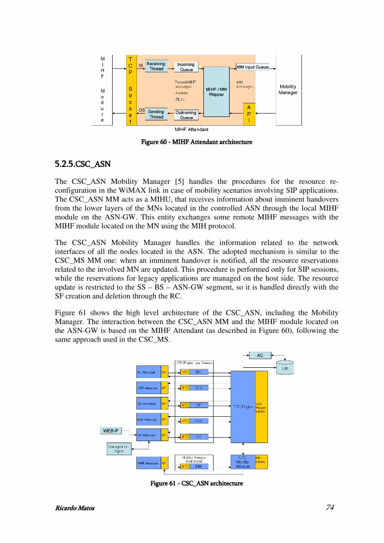
Ricardo MatoRicardo MatoRicardo MatoRicardo Matossss 74
Figure Figure Figure Figure 60606060 ---- MIHF Attendant architecture MIHF Attendant architecture MIHF Attendant architecture MIHF Attendant architecture
5.2.5.5.2.5.5.2.5.5.2.5.CSC_ASNCSC_ASNCSC_ASNCSC_ASN
The CSC_ASN Mobility Manager [5] handles the procedures for the resource re-configuration in the WiMAX link in case of mobility scenarios involving SIP applications. The CSC_ASN MM acts as a MIHU, that receives information about imminent handovers from the lower layers of the MNs located in the controlled ASN through the local MIHF module on the ASN-GW. This entity exchanges some remote MIHF messages with the MIHF module located on the MN using the MIH protocol.
The CSC_ASN Mobility Manager handles the information related to the network interfaces of all the nodes located in the ASN. The adopted mechanism is similar to the CSC_MS MM one: when an imminent handover is notified, all the resource reservations related to the involved MN are updated. This procedure is performed only for SIP sessions, while the reservations for legacy applications are managed on the host side. The resource update is restricted to the SS – BS – ASN-GW segment, so it is handled directly with the SF creation and deletion through the RC.
Figure 61 shows the high level architecture of the CSC_ASN, including the Mobility Manager. The interaction between the CSC_ASN MM and the MIHF module located on the ASN-GW is based on the MIHF Attendant (as described in Figure 60), following the same approach used in the CSC_MS.
Figure Figure Figure Figure 61616161 ---- CSC_ASN architectureCSC_ASN architectureCSC_ASN architectureCSC_ASN architecture

Ricardo MatoRicardo MatoRicardo MatoRicardo Matossss 75
The finite state machine managed by the CSC_ASN MM is based on the same approach of the CSC_MS MM. The main different is the mechanism adopted for the reconfiguration of the WiMAX link: at the CSC_MS level the NSIS signaling is used to request the SF creation and deletion, while at the CSC_ASN level the resource reconfiguration is directly managed through the interaction with the RC.
5.2.6.MIHF
MIHF is the central unit of IEEE 802.21 architecture. It provides communication with LLC (lower layers) and MIHUs (upper layers). Furthermore MIHF will have to communicate with remote MIHFs via NSIS. Figure 62 describes the relationship between MIHF and all mobility modules.
The MIHF interfaces with other layers and functional planes using Service Access Points (SAPs). Each SAP consists of a set of service primitives that specify the interactions between the service user and provider.
Figure Figure Figure Figure 62626262 ---- Relationship between different MIHF SAPsRelationship between different MIHF SAPsRelationship between different MIHF SAPsRelationship between different MIHF SAPs
The MIH_LINK_SAP specifies an abstract media dependent interface between the MIHF and lower layers media-specific protocol stacks of technologies such as IEEE 802.3, IEEE 802.11 and IEEE 802.16.
The MIH_NET_SAP specifies an abstract media dependent interface of the MIHF which provides transport services over the data plane on the local node, supporting the exchange of MIH information and messages with remote MIHFs, using MIH protocol [5].
The MIH_SAP specifies a media independent interface between the MIHF and upper layers of the mobility management protocol stack, designed MIHUs.
5.2.7.5.2.7.5.2.7.5.2.7.Interaction Interaction Interaction Interaction
This section presents the interaction between the mobility modules.
At a first stage a MIHU of a defined domain (MS or ASN-GW) should register it in the properly MIHF sending it a MIH_Register.request starting the register process as described in Figure 63.

Ricardo MatoRicardo MatoRicardo MatoRicardo Matossss 76
Figure Figure Figure Figure 63636363 ---- MIHU Register MIHU Register MIHU Register MIHU Register
At a second stage MIHUs have to subscribe in MIHF the events that want to receive. The subscription may be required by a local MIHU or a remote MIHU. Figure 64 describes the subscription of events of MIHUs at MIHF.
FFFFigure igure igure igure 64646464 ---- MIHU Event Subscribe MIHU Event Subscribe MIHU Event Subscribe MIHU Event Subscribe
The next procedure in a mobility scenario using IEEE 802.21 architecture is the forward of the events that Lower Layer Controller (LLC) triggers. MIHF should send them only to MIHUs which have subscribed such type of event.
First of all the LLC should detect the interfaces that are available and send this information to MIHF. At this case Ethernet and Wireless interfaces are both up (see Figure 65).
MIHF should forward the messages to Mobility Managers because they are the main responsible about all the questions related with mobility and it have to trigger the resource reservation on the new WiMAX segment when an handover procedure is necessary.
When we want to move from one interface to another Lower Layer Controller should send a Link_Going_Down event (see Figure 66) to Mobility Manager which triggers the resource reservation on the new WiMAX segment when an handover procedure is

Ricardo MatoRicardo MatoRicardo MatoRicardo Matossss 77
necessary. The Mobility Manager should send a notification to MIHF about the end of this process (in this case a Link_Action.request message).
When a user unplugs the Ethernet cable its communication with the rest of the world should be made by wireless interface and it is from this way that mobility manager receives a Link_Down event (see Figure 67).
Figure Figure Figure Figure 65656565 ---- Link_Up Event p Link_Up Event p Link_Up Event p Link_Up Event processingrocessingrocessingrocessing
Figure Figure Figure Figure 66666666 ---- Link_Going_Down E Link_Going_Down E Link_Going_Down E Link_Going_Down Event processingvent processingvent processingvent processing

Ricardo MatoRicardo MatoRicardo MatoRicardo Matossss 78
Figure Figure Figure Figure 67676767 ---- Link_Down E Link_Down E Link_Down E Link_Down Event processingvent processingvent processingvent processing
5.3.5.3.5.3.5.3.MIHF ImplementationMIHF ImplementationMIHF ImplementationMIHF Implementation
This section provides the specification of the MIHF, explaining its functionalities and its intelligence. MIHF implementation follows a set of steps, which are necessary for the proper integration of the module with the rest of the architecture. This module had to be made the most general possible, because it has to run not only in the MS but also in the ASN-GW and in CSN. Figure 68 shows the principal features of the MIHF architecture. As we can see initially we have to configure all the topology of the network with the important information of MIHFs, MIHUs and LLCs. It follows the creation of means of communication (sockets) with all modules. After this MIHF are able to receive any message from MIHUs, LLCs or NSIS and have the correct behaviour accordingly with the message received. The main MIHF functions, which will be described in the following sections, are:
• Configuration and topology;
• MIHF Engine;
• LLC message process;
• MIHU Message process;
• NSIS message process.

Ricardo MatoRicardo MatoRicardo MatoRicardo Matossss 79
Figure Figure Figure Figure 68686868 ---- MIHF intelligence MIHF intelligence MIHF intelligence MIHF intelligence
5.3.1.5.3.1.5.3.1.5.3.1.Configuration and TopologyConfiguration and TopologyConfiguration and TopologyConfiguration and Topology
It was decided to store all existing MIHFs (both the MS as the ASN-GW and in CSN) in a map (a data structure of the stdlib C++), and have a global variable indicating the location of MIHF in we are working. This is important because we have always access to all MIHFs and so, we know immediately if the information that arrives is local or remote. Each element of the map store relevant information about each MIHF. The MIHF struct is described in Table 8.
Parameter Name Parameter Type
MIHFIndex unsigned int MIHFPort unsigned int
MIHFName unsigned char* MIHFMacAddr unsigned char* MIHFIPv4Addr unsigned char*
MIHFID unsigned int MIHFEvents unsigned char
CommandElem map<unsigned int, Event> EventElem map<unsigned int, Command>
ServiceElem map<unsigned int, Service> InformationElem map<unsigned int, Information>
sockMIHU ServerSocket
Table Table Table Table 8888 ---- MIHF s MIHF s MIHF s MIHF structtructtructtruct
All existing MIHUs were also structured in a map of MIHUs. Each element of the map store relevant information about each MIHU. It was found a way of having a link between each MIHU and its local MIHF. The MIHF struct is described in Table 9.

Ricardo MatoRicardo MatoRicardo MatoRicardo Matossss 80
Parameter Name Parameter Type
MIHUIndex unsigned int MIHFIndex unsigned int MIHUPort unsigned int
MIHUName unsigned char* MIHUMacAddr unsigned char* MIHUIPv4Addr unsigned char*
MIHUNSIS unsigned int MIHFDestId unsigned int MIHFName unsigned char*
CommandElem map<unsigned int, Event> EventElem map<unsigned int, Command>
ServiceElem map<unsigned int, Service> InformationElem map<unsigned int, Information>
sockMIHU ServerSocket
Table Table Table Table 9999 ---- MIHU struct MIHU struct MIHU struct MIHU struct
All existing physical layers (LLCs) were also structured in a map. The physical layer struct is described in Table 10.
Parameter Name Parameter Type
L2Index unsigned int MIHFIndex unsigned int
L2Port unsigned int L2Name unsigned char*
L2MacAddr unsigned char* L2IPv4Addr unsigned char* MIHFName unsigned char*
sockL2 ServerSocket
Table Table Table Table 10101010 ---- Physical Layer struct Physical Layer struct Physical Layer struct Physical Layer struct
Each MIHF has associated maps of events, commands, information services and elements of control that provides. Each MIHU will also be associated themselves these sets of maps, after having subscribe each one of these services. These services are structured as shown in Table 11.
Struct Name Parameter Name Parameter Type
EventIndex unsigned int
event unsigned char Event
transactionID vector<int> CommandIndex unsigned int
command unsigned char Command
transactionID vector<int> InformationIndex unsigned int
information unsigned char Information
transactionID vector<int> ManagementIndex unsigned int
management unsigned char Management
transactionID vector<int>
Table Table Table Table 11111111 ---- MIHF and MIHU services MIHF and MIHU services MIHF and MIHU services MIHF and MIHU services struct struct struct struct
To store the important information about the MIHF and its location, about MIHUs and LLCs, it was defined a configuration file (MIHF.conf) which should be update before the start of a new test with MIHF if necessary.

Ricardo MatoRicardo MatoRicardo MatoRicardo Matossss 81
5.3.2.5.3.2.5.3.2.5.3.2.MIHF Engine MIHF Engine MIHF Engine MIHF Engine
The MIHF Engine is the central structure of the entire code.
Each MIHF has a set of listening TCP sockets. Each one is responsible for communicating with each MIHU associated with it. For a local MIHF communication with a remote one will be used NSIS (see section 5.2.2). In the communication with LLC, MIHF will be the client and LLC will be the server.
For the communication between modules we established a C++ class (‘Socket’ and the derived ‘ServerSocket’) with some methods that provide all the requirements to the communication between all the modules. They provide the accepting, listening and binding of a new element that communicates with MIHF and the reception and sending of messages between it and MIHF. After the creation of the sockets, MIHF are able to receive messages from the different interfaces and have the correct procedure whether the message reaches from LLC interface or from MIHU or NSIS interface.
After the creation of the sockets MIHF stays in a loop, listening if there is any message from an interface. If there is something, it should instantiate an object which allows the processing of these messages, calling the function L2MsgProcess(), MIHUMsgProcess() or NSISMSgProcess() as it is a LLC, a MIHU or NSIS.
5.3.3.5.3.3.5.3.3.5.3.3.L2L2L2L2 Message Process Message Process Message Process Message Process
The MIHF must have the ability to receive messages from the LLC (Link_Up.indication, Link_Down.indication or Link_Going_Down.indication). After that must process these messages, identify the event in question (Link_Up, Link_Down or Link_Going_Down) and forward it to the MIHUs (local or remote-via NSIS) that subscribe it. Figure 69 describes the receiving of LLC events by MIHF.
Figure Figure Figure Figure 69696969 ---- Receiving LLAReceiving LLAReceiving LLAReceiving LLA E E E Eventventventvent
If at the moment of the reception of the LLC message by MIHF, no MIHU had registered the MIHF or had subscribed its events, the events have to be stored in a struct. Later, when a new MIHU subscribes any event, we have to verify in this struct if there is an important event and send the correct information from a specific Layer 2 to the MIHU in question.

Ricardo MatoRicardo MatoRicardo MatoRicardo Matossss 82
5.3.4.5.3.4.5.3.4.5.3.4.MIHU and NSIS Message ProcessMIHU and NSIS Message ProcessMIHU and NSIS Message ProcessMIHU and NSIS Message Process
• MIHU Register
The MIHF must have the ability to receive messages coming from MIHUs who want to register (MIH_Register.request). The registration may be requested by a local MIHU or a remote MIHU. Moreover must generate and submit their response to these requests (MIH_Register.response). Figure 70 describes the register of MIHUs at MIHF.
Figure Figure Figure Figure 70707070 ---- Receiving MIHU RegisterReceiving MIHU RegisterReceiving MIHU RegisterReceiving MIHU Register
• MIHU Subscribe
The MIHF must have the ability to receive messages coming from MIHUs which want to subscribe their events (MIH_Event_Subscribe.request). The subscription may be required by a local MIHU or a remote MIHU. Moreover must generate and submit their response to these requests, indicating if it supports or not the requested events (MIH_Event_Subscribe.response). Figure 71 describes subscription of events by MIHUs at MIHF.
Figure Figure Figure Figure 71717171 ---- Receiving MIHU Event SubscribeReceiving MIHU Event SubscribeReceiving MIHU Event SubscribeReceiving MIHU Event Subscribe
• MIHU Link Action
The MIHF must have the ability to receive MIH_Link_Action.request and send the respective answer to all MIHUs or LLCs, who signed this type of command as described in Figure 72.

Ricardo MatoRicardo MatoRicardo MatoRicardo Matossss 83
Figure Figure Figure Figure 72727272 ---- Receiving MIHU Link ActionReceiving MIHU Link ActionReceiving MIHU Link ActionReceiving MIHU Link Action
• MIHU Link Up, MIHU Link Down, MIHU Link Going Down
As mentioned previously, MIHF should be able to forward the events that are coming from LLC for MIHUs that subscribed them, whether they local or remote, as described in Figure 69. For this, it should be defined the following primitives: MIH_Link_Up.indication, MIH_Link_Down.indication and MIH_Link_Going_Down.indication.
• MIHU Get Information
The MIHF must have the ability to receive messages coming from MIHUs who want to get information about the network topology (MIH_Get_Information.request). It has to forward these messages to the CSN, where resides the MIIS (Media Independent Information Service) which provides a framework and corresponding mechanisms by which the MIHF entity may discover and obtain network information existing within a geographical area to facilitate the handovers.
5.4.5.4.5.4.5.4.MessaMessaMessaMessages exchanged between Mobility Mges exchanged between Mobility Mges exchanged between Mobility Mges exchanged between Mobility Modulesodulesodulesodules
This section presents with more detail the MIHF interfaces (including the format of the primitives using such interface) through which LLC, MIHUs and remote MIHFs are able to communicate with local MIHF.
The received message from any interface is always processing at the same manner accordingly with the MIH protocol [5]:
• Read the header of the message to know the message in question.
• As the messages are sent accordingly with the IEEE 802.21 Draft Standard for Media Independent Handover Services, we have to read the type of TLV that follows the header.
• Next, we have to read the length of the TLV.

Ricardo MatoRicardo MatoRicardo MatoRicardo Matossss 84
• Finally, we have to read the value of the TLV.
5.4.1.MIH_LINK_SAP Interface
The interface between the LLC and the MIHF (MIH_LINK_SAP) is described in this section (according to the IEEE 802.21 [5]).
This interface will be implemented via a TCP Socket.
At this interface arrive service events, which come from LLC. All of these events have to be processed by MIHF and propagated for MIHUs that subscribed them (can be local or remote). This interface is also be used to propagate commands for LLC.
The structure of primitives, which represents these events, is described in Figure 73.
Figure Figure Figure Figure 73737373 ---- MIH_LINK_SAP Frame FormatMIH_LINK_SAP Frame FormatMIH_LINK_SAP Frame FormatMIH_LINK_SAP Frame Format
5.4.1.1.MIH_LINK_SAP Header
The MIH_LINK_SAP Header structure is presented in Figure 74.
Figure Figure Figure Figure 74747474 ---- MIH_LINK_SAP Header StructureMIH_LINK_SAP Header StructureMIH_LINK_SAP Header StructureMIH_LINK_SAP Header Structure
The MIH_LINK_SAP Header fields are presented Table 12. Field name Size
(bits)
Description
Service Identifier (SID)
8 Identifies the different MIH services, possible values are: 1: Service Management 2: Event Service 3: Command Service 4: Information Service
Operation Code (Opcode)
8 Type of operation to be performed with respect to the SID, possible values are: 1: Request 2: Response 3: Indication
Action Identifier (AID) 8 This indicates the action to be taken with regard to the SID
Table Table Table Table 12121212 ---- Description of MIH_LINK_SAP Header fieldsDescription of MIH_LINK_SAP Header fieldsDescription of MIH_LINK_SAP Header fieldsDescription of MIH_LINK_SAP Header fields
5.4.1.2.MIH_LINK_SAP Primitives

Ricardo MatoRicardo MatoRicardo MatoRicardo Matossss 85
When MIHF is connected to LLC via a TCP socket, it can receive three types of events: Link_Up, Link_Down and Link_Going_Down and the MIHF can send Link_Action command to LLC. Table 13 describes the parameters of those primitives.
Primitive Name Primitive Parameters
Link_Up.indication
Link Identifier MAC Old Access Router MAC New Access Router IP Renewal Flag Mobility Management Support
Link_Down.indication Link Identifier MAC Old Access Router Reason Code
Link_Going_Down.indication
Link Identifier Time Interval Confidence Level Link Going Down Reason Unique Event Identifier
MIH_LINK_SAP
Interface
Link_Action.request PoAMACAddress LinkAction ExecutionDelay
Table Table Table Table 13131313 ---- MIH_LINK_SAPMIH_LINK_SAPMIH_LINK_SAPMIH_LINK_SAP primitivesprimitivesprimitivesprimitives
• Link_Up.indication
This primitive is used by the LLC to notify the MIHF that a layer 2 connection is established on the specified link interface.
• Link_Down.indication
This primitive is used by the LLC to notify the MIHF that the layer 2 connection is broken on the specified link.
• Link_Going_Down.indication
This primitive is used by the LLC to notify the MIHF that the layer 2 connection is expected to go down within a certain time interval.
• Link_Action.request
This primitive is used by the MIHF to request an action on a link layer connection to enable optimal handling of link layer resources for the purpose of handovers. The link layer connection can be ordered, e.g., to shut down, to remain active, to perform a scan, or to come up active and remain in stand-by mode. The command execution delay time can also be specified for cases where the link layer technology under consideration supports the action.
More details about the content of those primitives are available in chapter 11.
5.4.2.MIH_NET_SAP Interface

Ricardo MatoRicardo MatoRicardo MatoRicardo Matossss 86
The interface between the MIHFs (MIH_NET_SAP) using NSIS is described in this section (according to the IEEE 802.21 [5]).
This interface will be implemented via a TCP Socket.
This interface provides the exchange of services (events, commands, management or information) between a pair of MIHFs, which is designed remote information.
MIHF could be used in mobile nodes and also in entities located in the network (ASN-GW or CSN). The MIHFs in MS and network entities communicate with each other using the MIH protocol messages [5]. The MIH protocol allows any peer MIH Function entities to communicate with each other.
The structure of primitives at this interface, based in MIH protocol, is described in Figure 75.
Figure Figure Figure Figure 75757575 ---- MIH_NET_SAP Frame Format MIH_NET_SAP Frame Format MIH_NET_SAP Frame Format MIH_NET_SAP Frame Format
5.4.2.1.MIH_NET_SAP Header
The MIH Protocol Header structure is presented in Figure 76.
Figure Figure Figure Figure 76767676 ---- MIH Protocol Header Structure MIH Protocol Header Structure MIH Protocol Header Structure MIH Protocol Header Structure
The MIH Protocol Header fields are presented in Table 14.

Ricardo MatoRicardo MatoRicardo MatoRicardo Matossss 87
Name Size
(bits) Description
Version 4 This field is used to specify the version of MIH protocol used. 0: Not to be used 1: First version 2 - 15: (Reserved)
ACK-Req 1 This field is used for requesting an acknowledgement for the message
ACK-Rsp 1 This field is used for responding to the request for an acknowledgement for the message
Unauthenticated Information
Request (UIR)
1 This field is used by the MIH Information Service to indicate if the protocol message is sent in pre-authentication/pre-association state so that the length of the response message can be limited
Reserved 9 This field is intentionally kept reserved. When not used, all the bits of this field are to be set to '0'
MIH Message ID (MID) 16 Combination of the following 3 fields --Service Identifier (SID) 4 Identifies the different MIH services, possible values are:
1: Service Management 2: Event Service 3: Command Service 4: Information Service
--Operation Code (Opcode) 2 Type of operation to be performed with respect to the SID, possible values are: 1: Request 2: Response 3: Indication
-- Action Identifier (AID) 10 This indicates the action to be taken with regard to the SID Transaction ID 16 This field is used for matching Request and Response, as well as
matching Request, Response and Indication to an ACK Variable Load Length 16 Indicates the total length of the variable load embedded in this
MIH protocol frame. The length of the MIH protocol header is NOT included
Table Table Table Table 14141414 ---- MIH Protocol Header fields MIH Protocol Header fields MIH Protocol Header fields MIH Protocol Header fields
5.4.2.2.MIH_NET_SAP Primitives
Through this interface will arrive requests for registering and event subscribing by remote MIHFs On other hand this interface has to forward services for remote MIHFs.
Because of this, should be defined the following primitives: MIH_Register (request and response), MIH_Event_Subscribe (request and response), MIH_Get_Information (request and response), MIH_Link_Action, MIH_Link_Up, MIH_Link_Down and, finally, MIH_Link_Going_Down. Table 15 describes the parameters of those primitives.

Ricardo MatoRicardo MatoRicardo MatoRicardo Matossss 88
Primitive Name Primitive Parameters
MIH_Register.request Source Identifier Destination Identifier RequestCode
MIH_Register.response
Source Identifier Destination Identifier ValidTimeInterval Status
MIH_Event_Subscribe.request
Source Identifier Destination Identifier LinkIdentifier RequestedMihEventList
MIH_Event_Subscribe.response
Source Identifier Destination Identifier LinkIdentifier ResponseMihEventList Status
MIH_Link_Up.indication
Source Identifier Destination Identifier LinkIdentifier MacOldAccessRouter MacNewAccessRouter IPRenewalFlag MobilityManagementSupport
MIH_Link_Down.indication
Source Identifier Destination Identifier LinkIdentifier MacOldAccessRouter Reason Code
MIH_Link_Going_Down.indication
Source Identifier Destination Identifier LinkIdentifier TimeInterval ConfidenceLevel LinkGoingDownReason UniqueEventIdentifier
MIH_Get_information.request
Source Identifier Destination Identifier InfoQueryBinaryDataList InfoQueryRDFDataList InfoQueryRDFSchemaURL InfoQueryRDFSchemaList MaxResponseSize
MIH_Get_information.response
Source Identifier Destination Identifier InfoResponseBinaryDataList InfoResponseRDFDataList InfoResponseRDFSchemaURLList InfoResponseRDFSchemaList Status
MIH_NET_S
AP Interface
MIH_Link_Action.request Source Identifier Destination Identifier Link Actions List
Table Table Table Table 15151515 ---- MIH_NET_SAP MIH_NET_SAP MIH_NET_SAP MIH_NET_SAP primitivesprimitivesprimitivesprimitives

Ricardo MatoRicardo MatoRicardo MatoRicardo Matossss 89
• MIH_Register.request
This message is transmitted to the remote MIHF to perform a registration or pre-registration.
• MIH_Register.response
This message is sent in response to a registration or re-registration request.
• MIH_Event_Subscribe.request
This message is sent by an MIHF to subscribe to one or more events from a particular MIHF.
• MIH_Event_Subscribe.response
This response indicates which of the requested events were successfully subscribed.
• MIH_Link_Up.indication
This notification is delivered from an MIHF when a layer 2 connection is up.
• MIH_Link_Down.indication
This notification is delivered from an MIHF when a layer 2 connection is down.
• MIH_Link_Going_Down.indication
This notification is delivered from an MIHF when a layer 2 connection is expected to go down.
• MIH_Get_Information.request
This message is used by an MIHF to retrieve a set of Information Elements provided by the information service.
• MIH_Get_Information.response
This is used as a response to the MIH_Get_Information request message. In one response message, one or more results can be returned.
• MIH_ Link_Action.request
This message is used to control the behavior of a set of lower link layer.
More details about the content of those primitives are available in chapter 11.

Ricardo MatoRicardo MatoRicardo MatoRicardo Matossss 90
5.4.3.MIH_SAP Interface
The interface between the MIHF and the MIHU (MIH_SAP) is described in this section (according to the IEEE 802.21 [5]).
This interface will be implemented via a TCP Socket.
This SAP defines the media independent interface between the MIHF and MIHUs such as an upper layer mobility protocol or a handover function which might reside at higher layers or a higher layer transport entity as well. It provides the exchange of services (events, commands, information and management) between a MIHUs and its MIHF.
The structure of primitives at this interface is based in MIH protocol, as described for MIH_NET_SAP interface.
5.4.3.1.MIH_SAP Header
The MIH Protocol Header structure was presented in section 5.4.2.1.
5.4.3.2.MIH_SAP Primitives
Through this interface will arrive requests for registering and event subscribing by the MIHUs of a MIHF. On other hand this interface has to forward LLC events for local MIHUs.
Because of this, should be defined the following primitives: MIH_Register (request and confirm), MIH_Event_Subscribe (request and confirm), MIH_Link_Up, MIH_Link_Down and finally, MIH_Link_Going_Down, MIH_Get_Information (request and confirm), MIH_Link_Action. Table 16 describes the parameters of those primitives.

Ricardo MatoRicardo MatoRicardo MatoRicardo Matossss 91
Primitive Name Primitive Parameters
MIH_Register.request Destination Identifier RequestCode
MIH_Register.confirm Source Identifier ValidTimeInterval Status
MIH_Event_Subscribe.request Destination Identifier LinkIdentifier RequestedMihEventList
MIH_Event_Subscribe.confirm
Source Identifier LinkIdentifier ResponseMihEventList Status
MIH_Link_Up.indication
Source Identifier LinkIdentifier MacOldAccessRouter MacNewAccessRouter IPRenewalFlag MobilityManagementSupport
MIH_Link_Down.indication
Source Identifier LinkIdentifier MacOldAccessRouter Reason Code
MIH_Link_Going_Down.indication
Source Identifier LinkIdentifier TimeInterval ConfidenceLevel LinkGoingDownReason UniqueEventIdentifier
MIH_Get_Information.request
DestinationIdentifier InfoQueryBinaryDataList InfoQueryRDFDataList InfoQueryRDFSchemaURL InfoQueryRDFSchemaList MaxResponseSize
MIH_Get_Information.confirm
SourceIdentifier InfoResponseBinaryDataList InfoResponseRDFDataList InfoResponseRDFSchemaURL InfoResponseRDFSchemaList Status
IH_SAP
Interface
MIH_Link_Action.request Destination Identifier Link Actions List
Table Table Table Table 16161616 ---- MIH_SAP MIH_SAP MIH_SAP MIH_SAP primitivesprimitivesprimitivesprimitives
• MIH_Register.request
This primitive is used by an MIHU to register the local MIHF with a remote MIHF.
• MIH_Register.confirm
This primitive is used by the local MIHF to convey the result of the registration request to the MIHU.
• MIH_Event_Subscribe.request

Ricardo MatoRicardo MatoRicardo MatoRicardo Matossss 92
This primitive is used by an MIHU to subscribe to one or more MIH events from a local or a remote MIHF.
• MIH_Event_Subscribe.confirm
This primitive returns the result of an MIH event subscription request.
• MIH_Link_Up.indication
This primitive is sent by the MIHF to notify the MIHU that a specific link layer technology is up.
• MIH_Link_Down.indication
This primitive is sent by the MIHF to notify the MIHU that a specific link layer technology is down.
• MIH_Link_Going_Down.indication
This primitive is sent by the MIHF to notify the MIHU that a specific link layer technology is going to be down.
• MIH_Get_Information.request
This primitive is used by an MIH User to request information from an MIH information server. The information query may be related to a specific interface, attributes to the network interface, as well as the entire network capability..
• MIH_Get_Information.confirm
This primitive is generated by the MIHF to respond to a MIH_GET_Information.confirm primitive.
• MIH_Link_Action.request
This primitive is used by the MIHU to control the behavior of a set of local or remote lower layer links.
More details about the content of those primitives are available in chapter 11.
5.5.5.5.5.5.5.5.SummarySummarySummarySummary
In this chapter the WEIRD’s phase 2 architecture was presented. The mobility architecture developed in the WEIRD’s framework aims to demonstrate the correct integration between IEEE 802.21 architecture and Mobile IP through WiMAX segments. In the framework of the mobility scenario, a MIHF module was specified and implemented. It provides communication with LLC (lower layers) and MIHUs (upper layers). Furthermore, MIHF will have to communicate with remote MIHFs via NSIS. MIHF provides a set of events,

Ricardo MatoRicardo MatoRicardo MatoRicardo Matossss 93
commands, information and management services that can be subscribed by MIHUs. MIHUs take decisions of handover based on information received from MIHF. All of this provides the seamless handover between networks of the same (HO Horizontal) or different technologies (HO Vertical) being independent of the physical networks.

Ricardo MatoRicardo MatoRicardo MatoRicardo Matossss 94
6.6.6.6.Mobility: Real ExpMobility: Real ExpMobility: Real ExpMobility: Real Experimental Scenarios and Resultserimental Scenarios and Resultserimental Scenarios and Resultserimental Scenarios and Results
In this chapter we will evaluate the WEIRD’s (WiMAX Extension to Isolated Research Data networks) phase 2 architecture [5], in which it is included the MIHF (Media Independent Handover Function) described in chapter 5, in a real mobility scenario with the integration of MIPv4 and resource allocation at the WiMAX (Worldwide Interoperability for Microwave Access) equipment. We will also evaluate the signalling of the second phase of the WEIRD project, comparing them with the signalling of the first phase, in the resource allocation at the WiMAX equipment.
Section 6.1 depicts the scenario implemented to evaluate the mobility mechanisms in the second phase of the project and the results obtained with the performed tests, such as, the values for signalling in the resource allocation at this stage of WEIRD project, and the processing times related with MIHF. Section 6.2 presents a scenario to evaluate advanced mobility questions, whereas section 6.3 presents a brief overview of the chapter.
6.1.6.1.6.1.6.1. Mobility SMobility SMobility SMobility Scenario cenario cenario cenario
This section explains the mobility scenario and its three phases. We tested the mobility mechanism, as demonstrated in Figure 77:
• The testbed is composed by the CSN (Connectivity Service Network), the ASN (Access Service Network) and the MS (Mobile Station).
• Under the ASN we have the BS (Base Station) directly connected to the ASN-GW.
• Two SSs (Subscriber Stations) are connected to the BS creating a Point-to-Multipoint (PMP) topology.
• The MS can be connected to SS1 by Ethernet and to SS2 by WiFi.
• The server was located in CSN and the client in the MS.
• Note that the IPs [16] of the different interfaces was defined firstly, like the figure presents.
• Because of the mobility questions related with MIPv4, we can see that was specified the Home Network and the Home Agent, the Foreign Network and the Foreign Agent, and the Mobile Node.

Ricardo MatoRicardo MatoRicardo MatoRicardo Matossss 95
Figure Figure Figure Figure 77777777 ---- Mobility Scenario Mobility Scenario Mobility Scenario Mobility Scenario
The goal of this scenario is to demonstrate a handover between Ethernet and WiFi, backhauled by a fixed WiMAX link (802.16d). The main technologies accomplishing this solution are the Mobile IP (MIP) protocol, and the IEEE 802.21 - Media independent Handover standard. While the user is watching a Video received by Ethernet+WiMAX link on the MS, a vertical handover occurs. After this process, the user can continue to watch the Video by the WiFi+WiMAX link, experiencing the same video-quality. The video streaming server has been installed on the same node of the CSC_CSN module to demonstrate that the WEIRD’s signalling is still valid in the more general case where the Video Server application is located in the Core Network. WEIRD modules involved in this scenario are described in Table 17.
Module Description
VLC Client and Server Application CSC_MS Connectivity Server Controller located on the MS Low Level Controller (LLC) Monitoring the state of MS Network Interfaces WEIRD Agent (WA) Resource Reservation provisioning for Legacy Applications MIHF MIH Function (IEEE 802.21) NSIS (Next Step in Signaling) NSIS Signalling Generic and Specific Adapters (for Redline equipment
Service Flow management
Resource Controller (RC) Control the Resource Reservation on the ASN Gateway AAA Server Authentication, Authorization and Accounting Administration Console Control Plane Monitoring CSC_ASN Connectivity Service Controller located on the ASN Gateway CSC_CSN Connectivity Service Controller located on the Core Service
Network MIP Module (Home Agent, Foreign Agent, Mobile Node)
Agent enabling the Mobile IP protocol
Table Table Table Table 17171717 ---- WEIRD modules involved WEIRD modules involved WEIRD modules involved WEIRD modules involved

Ricardo MatoRicardo MatoRicardo MatoRicardo Matossss 96
6.1.1.Inter module signalling
With this scenario we want to see an Handover (HO) between Ethernet (SS1 is connected to Ethernet) and WiFi (SS2 is connected to WiFi), running video streaming application, using MIPv4 in a make before break topology. At the first part of the scenario (see Figure 78), the sequence of the events is the following:
• A pre-condition to begin is that both Ethernet and Wifi interfaces of the MS are configured and ready to be used.
• When the Lower Layer Agent (LLA) is started, it detects the status of the network interfaces and sends two Link_Up events to the MIHF.
• MIHF forwards these events to the Mobility Manager (MM) included into CSC_MS, so that the MM can update its internal state machine.
• The user can watch the status of the network interfaces by the LLA GUI. • The user triggers the Quality of Service (QoS) reservation process between SS1 and
BS by using the WA module. The WA GUI shows that the process has been completed successfully, when the WA receives the reply from the CSC_MS.
• The Network Administrator can monitor the control plane status by using the Administration Console: parameters and Service Flow associated to the new NSIS session can be known.
• The user can watch the video from the VLC Client.
Figure Figure Figure Figure 78787878 ---- State 1 State 1 State 1 State 1 –––– QoS Reservation QoS Reservation QoS Reservation QoS Reservation
At the second part of the scenario (see Figure 79), the sequence of the events is the following:
• The user uses the LLA GUI to notify the network that he/she is going to change the MS position.
• LLA sends the Link_Going_Down event to the MIHF.

Ricardo MatoRicardo MatoRicardo MatoRicardo Matossss 97
• MIHF forwards the received event to the Mobility Manager (MM) included into the CSC_MS.
• MM triggers the handover preparation by sending a HO reservation request through NSIS.
• When the MM receives the HO reservation response, it sends a MIH_Link_Action request the MIHF.
• MIHF forwards this request to the LLA. • The user can see that the HO preparation process has been completed successfully
by the LLA GUI. • The Network Administrator can monitor the control plane status by using the
Administration Console: the Service Flow transporting the data traffic is unchanged.
Figure Figure Figure Figure 79797979 ---- State 2 State 2 State 2 State 2 –––– Handover Preparation Handover Preparation Handover Preparation Handover Preparation
At the third part of the scenario (see Figure 80), the sequence of the events is the following:
• The user unplugs the Ethernet cable from the MS. • MN agent detects that the MS is no more connected to the Home Network and
identifies the FA presence in the WiFi network through the received Agent Advertisements.
• MN agent sends the Registration Request (MIP) to the FA which forwards the message to the HA.
• HA updates its internal tables and replies with a registration response (MIP) to the FA which forwards the message to the MN. At the end of these steps an IP over IP tunnel between HA and FA is established.
• LLA detects that the Ethernet cable has been unplugged and sends a Link_Down event to the MIHF.

Ricardo MatoRicardo MatoRicardo MatoRicardo Matossss 98
• MIHF forwards the received event to the Mobility Manager into the CSC_MS. • MM triggers the deletion of the Service Flows between SS_1 and BS_1 by sending
a HO Deletion Request through NSIS. • The user can watch the new Ethernet interface status by the LLA GUI. • The Network Administrator can monitor the control plane status by using the
Administration Console: parameters and Service Flow associated to the previous NSIS session are now updated.
• The user can watch the video from the VLC Client.
Figure Figure Figure Figure 80808080 ---- State 3 State 3 State 3 State 3 –––– Handover Process Handover Process Handover Process Handover Process
6.1.2.Performed tests
6.1.2.1.6.1.2.1.6.1.2.1.6.1.2.1.Processing times for resource alProcessing times for resource alProcessing times for resource alProcessing times for resource allocation location location location
At this section we will evaluate the processing times for resource allocation at the WiMAX equipment, comparing these values with the results presented in chapter 4. We will use the same scenario and conduct explained at section 4.3.1 for the point-to-point scenario. The main procedure is explained below:
• We sent all the logs produced by the different modules for different files (to optimize the processing times) and we have slightly changed the modules code in order to know when messages were sent or arrived them, using the time functions provided by the languages that were used to develop the software.
• We made 10 followed reservations in the equipment.

Ricardo MatoRicardo MatoRicardo MatoRicardo Matossss 99
• Before we start the request in Weird Agent, we have defined at the RedMAX Equipment a set of service flows in which the traffic will pass. We inserted at BS-SS1 WiMAX link two services flows based on MAC of the PC on the SS1 domain: one uplink and other downlink.
• We are also interested to obtain the processing times for signalling when there is some application traffic filling the WiMAX links. For this we add some VoIP traffic between the MS (located in SS side) and ASN (located in BS side) and perform some requests while this traffic is passing the WiMAX link. The VoIP traffic was generated like depicted in section 3.4.1.2 for the VoIP (without aggregation) case. We started measuring the signalling time without traffic from application, then with 50 VoIP flows flowing through WiMAX channels (both uplink and downlink), then we increased it for 100, 150 and finally to 200.
We didn’t use directly the mobility scenario explained at this section because the modules in a mobility scenario are waiting to a correctly order of events, and so, with this scenario we can’t perform 10 consecutive requests at the equipment.
So, we opted to use a point-to-point scenario in order to know the time processing in the communication between the different modules. Note that these measures give us also the knowledge of the resource allocation times in the State 1 and State 2 of the mobility scenario, because the modules are the same and the communication between them is also the same.
• In State 1 the resource allocation is done as the same manner that it is in a point-to-point scenario used.
• In State 2 the resource allocation is performed by CSC_MS and not by WA, but the processing time for the NSIS communication between CSC_MS and CSC_ASN and for communication between CSC_ASN and the equipment can be measured with this point-to-point scenario too.
6.1.2.1.1.6.1.2.1.1.6.1.2.1.1.6.1.2.1.1.ResultsResultsResultsResults
This section presents the signalling results.
With WEIRD’s phase 2 software, the percentage of successful requests made by WEIRD Agent is always 100%. While in phase 1, if the time performed by the request is too high the NSIS generated a time-out and the requests are not routed to the ASN, in phase 2 all the requests were sent to ASN, which give us already a great improvement compared to phase 1.
Figure 81 and Figure 82 show us the processing times for the communication with the equipment to perform the request of the service flow and for Diameter signalling (between CSC_ASN and AAA), respectively. It demonstrates that these two times are approximately constant, even increasing the VoIP flows through WiMAX. Note that while the processing time between the CSC_ASN and the equipment is quite similar to the WEIRD’s phase 1

Ricardo MatoRicardo MatoRicardo MatoRicardo Matossss 100
case, the diameter signalling is approximately ten times more slowly compared with the Diameter signalling of the first phase, mainly because of the higher complexity of the AAA in this case.
0 50 100 150 2007
8
9
10
11
12
13
14
15
16
17
WiM
AX
Cro
ss L
ayer
(ms)
Number of VoIP flows
Figure Figure Figure Figure 81818181 ---- Processing time between CSC_ Processing time between CSC_ Processing time between CSC_ Processing time between CSC_ASN and the Equipment ASN and the Equipment ASN and the Equipment ASN and the Equipment
0 50 100 150 2000
500
1000
1500
Dia
mete
r sig
nalli
ng (
ms)
Number of VoIP flows
Figure Figure Figure Figure 82828282 ---- Diameter Signalling Diameter Signalling Diameter Signalling Diameter Signalling
Figure 83 shows us the time taken by NSIS in the communication between MS->ASN, ASN->CSN and CSN->MS, respectively.
We can conclude that the communication between ASN and CSN is quite constant and presents a small value, mainly because it is done by Ethernet.
Attempting at MS->ASN processing time, we can conclude that it continues to increase when the VoIP traffic begins to increase and saturate the capacity of the WiMAX channel,

Ricardo MatoRicardo MatoRicardo MatoRicardo Matossss 101
but at this time the increasing is slower than for WEIRD’s phase 1 case, which give us another great improvement compared to phase 1.
For the NSIS communication between CSN->ASN->MS, the time starts to increase as in the MS->ASN case when the VoIP traffic under WiMAX channel begins to increase. But at this case the values are lower than for MS->ASN communication, because a piece of CSN->ASN->MS communication is done by Ethernet and not by WiMAX link.
0
500
1000
1500
2000
2500
3000
3500
4000
0 50 100 150 200
Number of VoIP flows
NS
IS (
ms)
CSN->ASN->MS
ASN->CSN
MS->ASN
FigurFigurFigurFigure e e e 83838383 ---- Processing time by NSIS Processing time by NSIS Processing time by NSIS Processing time by NSIS
As we can see in Figure 84, the processing time by CSCs increase between the different experiments. This demonstrates that its processing is affected by the delay of the signalling between the MS and ASN due of the increasing congestion of the WiMAX channel. Note that the processing time by CSC software is higher than in the first phase due its larger complexity.
0 50 100 150 2000
200
400
600
800
1000
1200
1400
1600
1800
2000
2200
CS
Cs p
rocessin
g t
ime (
ms)
Number of VoIP flows
Figure Figure Figure Figure 84848484 ---- Proc Proc Proc Processing time by CSC´sessing time by CSC´sessing time by CSC´sessing time by CSC´s

Ricardo MatoRicardo MatoRicardo MatoRicardo Matossss 102
Figure 85 demonstrates the end-to-end time processing when we perform a request in WA for resource allocation at the WiMAX link. We can see that he end-to-end time for signalling increases when the VoIP traffic under WiMAX channel begins to increase. Note that the increasing is slower, comparing it with the phase 1 of the project, which give us the idea that the modules were correctly enhanced to obtain more acceptable values in the resource allocation.
0 50 100 150 2000
1000
2000
3000
4000
5000
6000
7000
8000
9000
10000
End-t
o-E
nd (
ms)
Number of VoIP flows
Figure Figure Figure Figure 85858585 ---- End End End End---- to to to to----EEEEnd timend timend timend time
6.1.2.2.6.1.2.2.6.1.2.2.6.1.2.2.Processing times Processing times Processing times Processing times for MIHFfor MIHFfor MIHFfor MIHF
At this section we will present the measured times for the MIHF internal processing and communication between all the mobility modules. Figure 86 shows the MIHF processing times at different situations:
• When MIHF_MS does the forward of events sent by LLC, MIHF_MS have a processing time, since it receives the event from its forward, of nearly 210 µs when the forward is done for CSC_MS, or about 310 µs when the forward is done for MIHF_ASN.
• After receiving the Link_Action from CSC_MS, MIHF_MS delays 120 µs to process the message and do the forward of it for LLC.
• When MIHF_ASN receives the MIH messages from MIHF_MS, it has a processing time, since it receives these messages from its forward for CSC_ASN, of nearly 300/400 µs.
This demonstrates the good performance of MIHF, because it is a small processing time.
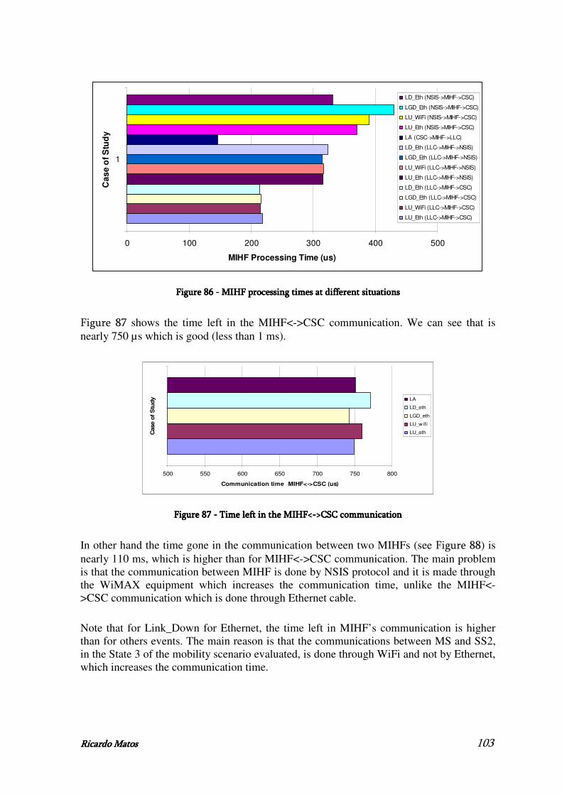
Ricardo MatoRicardo MatoRicardo MatoRicardo Matossss 103
0 100 200 300 400 500
1
Ca
se
of
Stu
dy
MIHF Processing Time (us)
LD_Eth (NSIS->MIHF->CSC)
LGD_Eth (NSIS->MIHF->CSC)
LU_WiFi (NSIS->MIHF->CSC)
LU_Eth (NSIS->MIHF->CSC)
LA (CSC->MIHF->LLC)
LD_Eth (LLC->MIHF->NSIS)
LGD_Eth (LLC->MIHF->NSIS)
LU_WiFi (LLC->MIHF->NSIS)
LU_Eth (LLC->MIHF->NSIS)
LD_Eth (LLC->MIHF->CSC)
LGD_Eth (LLC->MIHF->CSC)
LU_WiFi (LLC->MIHF->CSC)
LU_Eth (LLC->MIHF->CSC)
Figure Figure Figure Figure 86868686 ---- MIHF processing times at diffMIHF processing times at diffMIHF processing times at diffMIHF processing times at different situationserent situationserent situationserent situations
Figure 87 shows the time left in the MIHF<->CSC communication. We can see that is nearly 750 µs which is good (less than 1 ms).
500 550 600 650 700 750 800
1
Case o
f S
tudy
Communication time MIHF<->CSC (us)
LA
LD_eth
LGD_eth
LU_w if i
LU_eth
Figure Figure Figure Figure 87878787 ---- Time left in the MIHF< Time left in the MIHF< Time left in the MIHF< Time left in the MIHF<---->CSC >CSC >CSC >CSC communicationcommunicationcommunicationcommunication
In other hand the time gone in the communication between two MIHFs (see Figure 88) is nearly 110 ms, which is higher than for MIHF<->CSC communication. The main problem is that the communication between MIHF is done by NSIS protocol and it is made through the WiMAX equipment which increases the communication time, unlike the MIHF<->CSC communication which is done through Ethernet cable.
Note that for Link_Down for Ethernet, the time left in MIHF’s communication is higher than for others events. The main reason is that the communications between MS and SS2, in the State 3 of the mobility scenario evaluated, is done through WiFi and not by Ethernet, which increases the communication time.
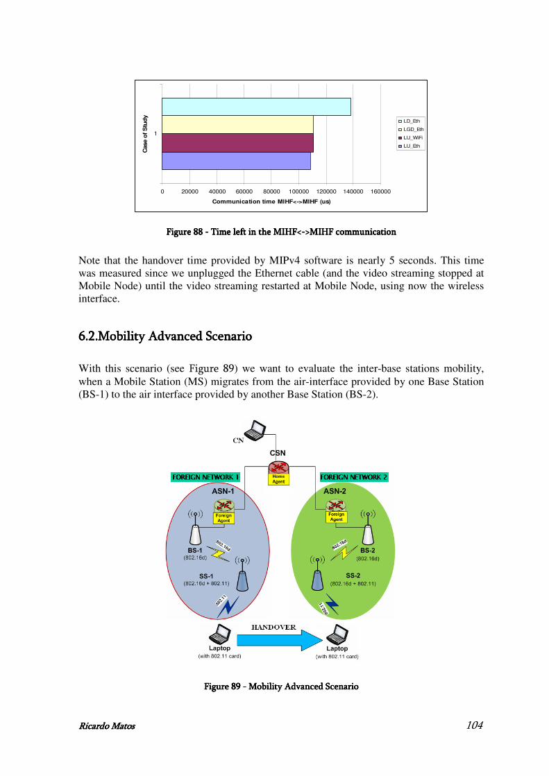
Ricardo MatoRicardo MatoRicardo MatoRicardo Matossss 104
0 20000 40000 60000 80000 100000 120000 140000 160000
1
Case o
f S
tud
y
Communication time MIHF<->MIHF (us)
LD_Eth
LGD_Eth
LU_WiFi
LU_Eth
Figure Figure Figure Figure 88888888 ---- Time left in the MIHF< Time left in the MIHF< Time left in the MIHF< Time left in the MIHF<---->MIHF communication>MIHF communication>MIHF communication>MIHF communication
Note that the handover time provided by MIPv4 software is nearly 5 seconds. This time was measured since we unplugged the Ethernet cable (and the video streaming stopped at Mobile Node) until the video streaming restarted at Mobile Node, using now the wireless interface.
6.2.6.2.6.2.6.2.MobiMobiMobiMobility Advanced Slity Advanced Slity Advanced Slity Advanced Scenariocenariocenariocenario
With this scenario (see Figure 89) we want to evaluate the inter-base stations mobility, when a Mobile Station (MS) migrates from the air-interface provided by one Base Station (BS-1) to the air interface provided by another Base Station (BS-2).
Figure Figure Figure Figure 89898989 ---- Mobility Mobility Mobility Mobility Advanced Advanced Advanced Advanced ScenarioScenarioScenarioScenario

Ricardo MatoRicardo MatoRicardo MatoRicardo Matossss 105
For this the MIHF should reside not only in the MS and in the ASN-GW, as before, but also in CSN in order to communicate with the Media Independent Information Service (MIIS) which has the information about the network topology.
Firstly the communication, between the server located on CSN side and the MN client, is done through Foreign Network 1, because the QoS resource allocation is performed through SS-1<->BS-1 domain, even when both WiFi interfaces are up. When the user wants to move, it sends a Link_Going_Down which is forwarded to Mobility Manager located on ASN-1. At this point, ASN-1 wants to know the network topology for the handover preparation. For this, it will send a MIH_Get_Information.request message to MIHF_ASN, which forwards it to MIHF_CSN, through NSIS signalling. MIHF_CSN will forward them to MIIS. Returned to MIHF_CSN, the MIH_Get_Information.response will be sent to the MIHF_ASN. The next step is the communication between CSC_ASN-1 and CSC_ASN-2 in order to allocate the necessary resources in SS-2<->BS-2 domain. After that the user can move to the Foreign Network 2 because all the handover preparation was done correctly.
Attempting at MIPv4 features, this type of handover can be described as the handover from a foreign (visited) network to another foreign (visited) network.
In one hand, the section 6.1 provides a scenario to show an HO transition between 802.3 and 802.11, both connected to a separate 802.16d SS (running a video-streaming application) and both 802.16d SS are connected to the same BS. In the other hand, this mobility advanced scenario shows an HO between two different 802.11 cells, both connected to a separate 802.16d SS, but each 802.16d SS is connected to a different BS and each BS is connected to a separate ASN.
6.3.6.3.6.3.6.3.SummarySummarySummarySummary
In this chapter we described all the processing times for WEIRD’s phase 2 architecture.
In the one hand, we conclude that the resource allocation at the WiMAX equipment at this second phase is done in a more properly way, which give us more acceptable values than for first phase of the project.
On the other hand we evaluate the MIHF processing times, which are totally accordingly with the requirements of a mobility architecture: fast to provide a seamless handover to the users.
We also explained a possible scenario to exploit mobility advanced questions, but due to unavailability of the remaining modules, it was not possible to evaluate this scenario in the timeframe of the Thesis.

Ricardo MatoRicardo MatoRicardo MatoRicardo Matossss 106
7.7.7.7.ConclusionConclusionConclusionConclusion
7.1.7.1.7.1.7.1.Final ConclusionFinal ConclusionFinal ConclusionFinal Conclusion
The work presented in this Thesis addressed key aspects of an architecture which is able to bring 802.16 technologies into play for the future next generation networks in compounded wireless environments, to perform end-to-end Quality of Service (QoS) and seamless mobility over heterogeneous networks: WiFi, WiMAX, 3GPP or 3GPP2.
Some of key aspects of the next generation networks were depicted in WEIRD (WiMAX Extension to Isolated Research Data networks) project and have been matter of concern all along the Thesis. In this Thesis, it was specified, developed, implemented and evaluated part of a network architecture with end-to-end QoS and mobility support over IEEE 802.16.
In this Thesis, it was evaluated the support of real-time services, such as VoIP and IPTV, over IEEE 802.16 in different modes of operation for the IEEE 802.16 system: point-to-point and point-to-multipoint. Thus, with the two different modes of operation, several tests with different characteristics were exploited, not only with Best Effort traffic but also establishing different service classes, in order to obtain the real capacities of RedMAX equipment at resource allocation. We concluded that our RedMAX’s equipment can sustain C = 50 emulated bidirectional Speex-encoded VoIP calls within the same WiMAX cell and 3 simultaneous emulated IPTV streams with negligible packet loss, adequate application-level throughput, and one way delays within proper bounds. Finally, VoIP aggregation appears to be a powerful method to improve performance and increase capacity utilization in a point-to-point scenario.
This Thesis also evaluated the QoS architecture of the first phase of the WEIRD project in order to control the resource allocation in the WiMAX equipment. This evaluation consisted on the processing times of all modules involved, the end-to-end time required for the establishing of a IEEE 802.16’s service flow, and the QoS achieved with the architecture. We concluded that the QoS specification done by the WEIRD software, for a specific application, is established correctly at the equipment. Unlike the point-to-point scenario, which gave us acceptable values for the signalling in the resource allocation at the WiMAX equipment, the point-to-multipoint scenario didn’t work in the correct manner in the WEIRD project.
The next phase of the Thesis was the specification and implementation of the central unit of IEEE 802.21 architecture called Media Handover Independent Function (MIHF), which was integrated in the WEIRD mobility architecture. This implementation was the materialization of the research work, in order to obtain seamless mobility support in next generation real environments. Moreover, it was demonstrated the correct functionality and flexibility of MIHF. Several tests were conducted to evaluate the enhancements provided by the mobility-enabled architecture with QoS and resource allocation support. We

Ricardo MatoRicardo MatoRicardo MatoRicardo Matossss 107
concluded that the MIHF processing times in the forward of the messages are totally accordingly to the requirements of a mobility architecture, providing fast processing.
The experiments accomplished along the project confirm expectations relating to the IEEE 802.16 technology in terms of performance, with real-time services and mobility support, and a variety of usage scenarios.
This Thesis shows that it is possible to integrate IEEE 802.16 technologies into new generation networks with seamless handover between different access networks, enabling end users to enjoy an “Always Best Connected” experience. The combination of these capabilities makes IEEE 802.16 attractive for a wide diversity of users and entities, not only for operators and wireless ISPs (Internet Service Provider), but also for many vertical markets and local authorities.
WiMAX is a technology with potential to succeed and it will soon become one of the most powerful wireless technologies in the market due to its several possible applications.
7.2.7.2.7.2.7.2.Future workFuture workFuture workFuture work
As future work, some improvements could be done in MIHF, such as, the implementation of all the messages related to the IEEE 802.21 standard.
Moreover, the advanced mobility scenario developed in this Thesis need to be integrated with the overall architecture to evaluate its performance.
Finally, the MIHF solution should implement the required functionalities to integrate with all possible access technologies, specifying the interfaces of communication between MIHF and lower layers.

Ricardo MatoRicardo MatoRicardo MatoRicardo Matossss 108
8.8.8.8.ReferencesReferencesReferencesReferences
[1] IEEE Std 802.16-2004, "IEEE Standard for Local and Metropolitan Area Networks,
Part 16: Air Interface for Fixed Broadband Wireless Access Systems", IEEE
Standard 802.16-2004, October 2004.
[2] IEEE Std 802.16e-2005, "IEEE Standard for Local and Metropolitan Area
Networks, Part 16: Air Interface for Fixed Broadband Wireless Access Systems –
Physical and Medium Access Control Layers for Combined Fixed and Mobile
Operation in Licensed Bands", IEEE Standard 802.16e-2005, February 2006.
[3] IEEE Std 802.21, "IEEE Standard for Local and Metropolitan Area Networks:
Media Independent Handover services", IEEE Standard 802.21/D07.00, July 2007.
[4] WEIRD Deliverable “D2.3 System Specification”, Version 1.2.2, May 2007.
[5] WEIRD Deliverable “D2.3 Final Implementation”, Version 0.1, May 2008.
[6] Neves Pedro, “Quality of Service in IEEE 802.16 Access Networks”, November
2006.
[7] Pereira Telmo, “Quality of Service and Mobility support in WiMAX Networks”,
November 2006.
[8] Solomon James , “Mobile IP: The Internet Umplugged”,1998.
[9] Zheng Wang, “Internet QoS: Architectures and Mechanisms for Quality of Service”,
2001.
[10] Guy Cayla, Stephane Cohen and Didier Guigon, “WiMAX an efficient tool to bridge
the digital divide”, November 2005.
[11] International Telecommunication Union, “Advanced video coding for generic
audiovisual services”, ITU-T Recommendation H.264, 2005.
[12] IETF draft-ieft-nsis-qos-nslp, “NSLP for Quality-of-Service Signalling”
[13] R. Hankock et al, ”Next Step in Signalling (NSIS): Framework”, RFC 4080, June
2005.
[14] R. Droms, Ed., J. Bound, et. Al.,” Dynamic Host Configuration Protocol for IPv6
(DHCPv6)”, RFC 3315, July 2003.
[15] Narten, T., E. Nordmark, W. Simpson, “Neighbour Discovery for IP Version 6”,
RFC 2461, December 1998.
Ricardo MatoRicardo MatoRicardo MatoRicardo Matossss 109
[16] Postel, J., "Internet Protocol", STD 5, RFC 791, September 1981.
[17] Braden, R., D. Clark, S. Shenker, “Integrated Services in the Internet Architecture:
an Overview”, RFC 1633, June 1994.
[18] Droms, R., "Dynamic Host Configuration Protocol", RFC 2131, March 1997.
[19] Deering, S. and R. Hinden, "Internet Protocol, Version 6 (IPv6) Specification", RFC
2460, December 1998.
[20] Johnson, D., C. Perkins, J. Arkko, “Mobility Support for IPv6”, RFC 3775, June
2004.
[21] Aboba, B. et al, "Criteria for Evaluating AAA Protocols for Network Access", RFC
2989, April 2000.
[22] J. Rosenberg et al., “SIP: Session Initiation Protocol”, RFC 3261, June 2002.
[23] P. Calhoun, J. Loughney, “Diameter Base Protocol”, RFC 3588, September 2003
[24] D. L. Mills, “Network Time Protocol (Version 3)”, RFC 1305, March 1992.
[25] H. Schulzrinne, A. Rao, and R. Lanphier,” Real Time Streaming Protocol (RTSP)”,
RFC 2326, April 1998.
[26] H. Schulzrinne, S. Casner, R. Frederick, and V. Jacobson,” RTP: A Transport
Protocol for Real-Time Applications”, RFC 3550, July 2003.
[27] S. Wenger, M. Hannuksela, T. Stockhammer, M. Westerlund, and D. Singer,” RTP
Payload Format for H.264 Video”, RFC 3984, February 2005.
[28] Pedro Neves, Susana Sargento, Rui L. Aguiar, “Support of Real-time Services over
Integrated 802.16 Metropolitan and Local Area Networks”, ISCC 2006, IEEE
Symposium on Computers and Communications, Cagliary, Italy, June 2006.
[29] E. Guainella, E. Borcoci, M. Katz, P. Neves, M.Curado, F. Andreotti, E. Angori,”
WiMAX Extension to Isolated Research Data Networks”, IEEE Mobile WiMAX
World Summit, Orlando (Florida), March 2007.
[30] E. Guainella, E. Borcoci, M. Katz, P. Neves, M.Curado, F. Andreotti, E. Angori,
“Extending WiMAX to Novel and Stringent Wireless Scenarios: An Introduction to
the WEIRD Project”, BroadBand Europe, Geneva, Switzerland, December 2006.
[31] E. Angori, E. Borcoci, S.Mignanti, C.Nardini, G.Landi, N.Ciullli, G.Sergio,
P.Neves, ”Extending WiMAX technology to support End to End QoS guarantees”,
WEIRD workshop, May 2007.
[32] E. Guainella, E. Borcoci, M. Katz, P. Neves, M.Curado, F. Andreotti, E. Angori,”

Ricardo MatoRicardo MatoRicardo MatoRicardo Matossss 110
WiMAX technology support for applications in environmental monitoring, fire
prevention and telemedicine”, IEEE Mobile WiMAX World Summit, Orlando
(Florida), March 2007.
[33] P. Neves, P.Simões, Á. Gomes, L. Mário, S.Sargento, F.Fontes, E. Monteiro, T.
Bohnert,”WiMAX for Emergency Services: An Empirical Evaluation”, International
Conference Next Generation Mobile Applications, Services and Technologies,
September 2007.
[34] K.Pentikousis, E.Piri, J. Pinola, F. Fitzek, T. Nissila, I. Harjula, ”Empirical
Evaluation of VoIP Aggregation over a Fixed WiMAX Testbed”, Tridentcom,
Innsbruck, Austria, March 2008.
[35] K. Correll, N. Barendt, and M. Branicky, “Design Considerations for Software Only
Implementations of the IEEE 1588 Precision Time Protocol,” Proc. Conference on
IEEE 1588, Winterthur, Switzerland, October 2005.
[36] B.Sousa, P.Neves, G. Leão, D. Palma, J. Silva, S. Sargento, F. Fontes, M. Curado, F.
Boavida, “The Cost of Using IEEE 802.16d Dynamic Channel Configuration”, ICC ,
Pequim, China, May 2008.
[37] P.Neves, T. Nissila, T. Pereira, I. Harjula, J. Monteiro, K. Pentikousis, S. Sargento,
F. Fontes,”A Vendor-Independent Resource Control Framework for WiMAX”,
ISCC , Marrakesh, Morocco, July 2008.
[38] M. Castrucci, N. Ciulli, A. Ichimescu, G. Landi, I. Marchetti, C. Nardini, P. Neves,
“A Framework for Resource Control in WiMAX Network”, BWA, Cardiff, Wales,
September 2007.
[39] K.Pentikousis, J. Pinola, E.Piri,, F. Fitzek, ”An Experimental Investigation of VoIP
and Video streaming over Fixed WiMAX”,2008.
[40] WiMAX Forum. URL: http://www.wimaxforum.org
[41] Redline Communications. URL: http://www.redlinecommunications.com
[42] IEEE 802.16 Working Group (WG), URL:http://www.ieee802.16.org/16
[43] DSL Forum, URL: http://www.dslforum.org
[44] Institute of Electrical and Electronics Engineers (IEEE).URL:http://www.ieee.org
[45] Wi-Fi Forum. URL: http://www.wi-fi.org
[46] International Telecommunication Union – Telecommunication Standardization
Sector. URL: http://www.itu.int/ITU-T/index.phtml

Ricardo MatoRicardo MatoRicardo MatoRicardo Matossss 111
[47] K. Correll, PTP daemon (PTPd).URL: http://ptpd.sourceforge.net.
[48] J.Manner, Jugi’s Traffic Generator (JTG).
URL:http://hoslab.cs.helsinki.fi/savane/projects/jtg
[49] J. M. Valin, Speex: A Free Codec for Free Speech. URL: http://www.speex.org.
[50] ISO/IEC, “Information technology - Coding of moving pictures and associated audio
for digital storage media at up to about 1.5 Mbit/s – Part 3: Audio”, ISO/IEC 11172-
3, 1993.
[51] ITU-T, “Dual rate speech coder for multimedia communications transmitting at 5.3
and 6.3 kbs”, ITU-T Recommendation G.723.1, 1996.
[52] S. Sengupta, M. Chatterjee, S. Ganguly, and R. Izmailov,” Improving R-Score of
VoIP streams over WiMAX”, In Proc. IEEE ICC 2006, volume 2, pages 866–871,
June 2006.
[53] ITU-T,” The E-Model, a computational model for use in transmission planning”,
ITU-T Recommendation G.107, December 1998.
[54] N. Scalabrino, F. D. Pellegrini, R. Riggio, A. Maestrini, C. Costa, and I. Chlamtac,
“Measuring the quality of VoIP traffic on a WiMAX testbed”, TRIDENTCOM,
pages 1–10, May 2007.
[55] R. G. Cole and J. H. Rosenbluth, ”Voice over IP performance monitoring,” ACM
SIGCOMM, volume 31, pages 9–24, April 2001.
[56] H.Schulzrinne, R. Hancock,“ GIST: General Internet Signalling Transport“,
Internet-Draft, August 2006

Ricardo MatoRicardo MatoRicardo MatoRicardo Matossss 112
9.9.9.9.Annex 1 Annex 1 Annex 1 Annex 1 –––– WEIRD phase 1 software installation and WEIRD phase 1 software installation and WEIRD phase 1 software installation and WEIRD phase 1 software installation and
cccconfigurationonfigurationonfigurationonfiguration
To successfully demonstrate the effectiveness of WEIRD’s phase 1 architectural solution in managing WiMAX resources it was developed a testbed.
This section resumes the different steps required to install and configure all the WEIRD’s phase 1 software. The software must be described according the different components of the WEIRD architecture, namely, the MS, the ASN, and the CSN.
9.1.9.1.9.1.9.1.Developed ArchitectureDeveloped ArchitectureDeveloped ArchitectureDeveloped Architecture
Figure 36 describes the WEIRD’s phase 1 architecture. As we can see, this architecture contains a set of modules (each one described in chapter 4). What is going to do is to test the proper communication between the different modules in order to determine the correct allocation of resources, for example, in a video streaming.
9.2.9.2.9.2.9.2.MSMSMSMS
• Running NSIS
For pre-requisites, we have to install sun-java5.0.
First we have to configure the IP for GIST in the nsis/conf/gist.conf file. This interface address corresponds to the IP address where the NSIS must run.
Second we have to configure the local IP address and the network for QoSNSLP by editing the nsis/conf/qosnslp.conf file.
To run this module we have to start the following scripts: nsis/start_gist.sh, nsis/start_qosnslp.sh and, finally, nsis/start_nsisatt.sh, on this order. Note that GSIT must be run as sudo.
Note that GIST and QoSNSLP generate logs, respectively the nsis/logs/gist.log and nsis/logs/qosnslp.logs files.
• Running CSC_MS
For pre-requisites, we have to install sun-java5.0 and mysql5.0.
Ricardo MatoRicardo MatoRicardo MatoRicardo Matossss 113
First we have to configure the options in the CSC_MS/csc.conf file. Note that NSIS must be started before the running of CSC_MS and it is running when we start CSC_MS/start_csc_ms.sh.
Note that CSC_MS generates output which can be redirected to a log file.
• Running Weird Agent
For pre-requisites, we have to install apache2.0, php5.0 and mysql5.0.
First we have to configure the options in the weird_agent/conf/conf-wa.php file, changing the values of CSC_MS_IP, CSC_MS_PORT and the variables to connect to the database server.
Second we have to create the weird_agent database by running the weird_agent/WA_db.sql script with mysql command, using the user “root” and the password “weird”.
Third we have to populate the table with the QoS characteristics of applications by running weird_agent/populateWADB.sql with mysql command.
Next we have to configure apache2.0 to run with PHP support and with an alias to directory where the WA is installed. This can be done at the file /etc/apache2/sites-available/default.
Finally we have start apache2.0, use the web browser and navigate to the URL configured in apache2: http://10.240.2.4/wa/.
Note that CSC_MS must be running before the running of WEIRD Agent.
Note that apache2.0 generates output which can be redirected to a log file.
9.3.9.3.9.3.9.3.CSNCSNCSNCSN
• Running NSIS
For pre-requisites, we have to install sun-java5.0.
First we have to configure the IP for GIST in the nsis/conf/gist.conf file. This interface address corresponds to the IP address where the NSIS must run.
Second we have to configure the local IP address and the network for QoSNSLP by editing the nsis/conf/qosnslp.conf file.
To run this module we have to start the following scripts: nsis/start_gist.sh, nsis/start_qosnslp.sh and, finally, nsis/start_nsisatt.sh, on this order. Note that GSIT must be run as sudo.

Ricardo MatoRicardo MatoRicardo MatoRicardo Matossss 114
Note that GIST and QoSNSLP generate logs, respectively the nsis/logs/gist.log and nsis/logs/qosnslp.logs files.
• Running CSC_CSN
For pre-requisites, we have to install sun-java5.0 and mysql5.0.
First we have to configure the options in the CSC_CSN/csc.conf file. Note that NSIS must be running before the running of CSC_CSN and it is running when we start CSC_CSN/start_csc_csn.sh.
Note that CSC_CSN generates output which can be redirected to a log file.
• Running AAA
For pre-requisites, we have to install sun-java5.0 and mysql5.0.
First we have to configure the AAA with the IP address of the localhost. For this we have to change in AAA/aaa/bin/conf/server_JDiameter.xml the value of the tag “transport_mngt,identity” with the IP address of the localhost.
Second we have to create and populate the users database by running the AAA/aaa/db/UsersDB.sql script with mysql command.
Third we have o configure the AAA to connect to the database. For this is necessary to change in AAA/aaa/bin/conf/AAAConfiguration.xml the values of the tag “db,users”, “db,pwd”, “db,host” with the username, password and IP address of the databases.
To run this module we have use the following command: java –jar AAAServer.jar in AAA/aaa/bin folder.
Note that AAA generates logs, respectively the AAA/aaa/bin/logs/aaa.log.log and AAA/aaa/bin/logs/aaa_verbose.log files.
9.4.9.4.9.4.9.4.ASNASNASNASN
• Running NSIS
For pre-requisites, we have to install sun-java5.0.
First we have to configure the IP for GIST in the nsis/conf/gist.conf file. This interface address corresponds to the IP address where the NSIS must run.
Second we have to configure the local IP address and the network for QoSNSLP by editing the nsis/conf/qosnslp.conf file.

Ricardo MatoRicardo MatoRicardo MatoRicardo Matossss 115
To run this module we have to start the following scripts: nsis/start_gist.sh, nsis/start_qosnslp.sh and, finally, nsis/start_nsisatt.sh, on this order. Note that GSIT must be run as sudo.
Note that GIST and QoSNSLP generate logs, respectively the nsis/logs/gist.log and nsis/logs/qosnslp.logs files.
• Running CSC_ASN
For pre-requisites, we have to install sun-java5.0 and mysql5.0.
First we have to configure the file CSC_ASN/conf/client_JDiameter.xml with the IP Address of the AAAServer (CSN) and the AAAAtendant (ASN).
Second we have to change populateDB.sql file accordingly with our network configuration.
Next we have to configure the options in the CSC_ASN/csc.conf file. Note that NSIS must be running before the running of CSC_ASN and it is running when we start CSC_ASN/start_csc_asn.sh.
Note that CSC_CSN generates output which can be redirected to a log file.
• Running RC
First we have to open the ASN_GW/RC/WIMAX_topology.cfg file and write the CSC_ASN IPv4 address, as well as the WiMAX network topology (Base Station and Subscriber Stations MAC/IPv4 addresses).
Second we have to compile the RC using the makefile located on folder ASN_GW/RC.
Next we have to just type on a Linux Terminal the following “./rc”.
Note that CSC_ASN must be started before the running of RC.
• Running Generic Adapter
First we have to compile the Generic Adapter, located on folder Generic_Adapter, using the following command: gcc –o generic_adapter generic_adapter.c -lpthread.
Second we have to check the configurations from “AI.h” and “GASAI.h” files to confirm that the IP and port numbers are correctly set for AI and GASAI interfaces.
Next we have to just type on a Linux Terminal the following: “./generic_adapter”.
Note that RC shall be started before the running of Generic Adapter.

Ricardo MatoRicardo MatoRicardo MatoRicardo Matossss 116
• Running Redline Adapter
First we have to compile the Redline Adapter using the makefile located on folder ASN_GW/Adapter/Redline_Adapter.
Next we have to just type on a Linux Terminal the following: “./RedlineAdapter GenericAdapterIPAddress”.
Note that Generic Adapter must be started before the running of Redline Adapter.
9.5.9.5.9.5.9.5.Important informationImportant informationImportant informationImportant information
All modules of the WEIRD’s architecture, necessaries for the testbed running, and described so far, are available by WEIRD project [4] . These folders are: nsis, CSC_MS, weird_agent, CSC_CSN, AAA, CSC_ASN, ASN_GW/RC, Generic_Adapter, ASN_GW/Adapter/Redline_Adapter. If there is a problem with any script, open it and make “set ff = unix”.

Ricardo MatoRicardo MatoRicardo MatoRicardo Matossss 117
10.10.10.10.Annex 2 Annex 2 Annex 2 Annex 2 –––– WEIRD phase 2 software installation and WEIRD phase 2 software installation and WEIRD phase 2 software installation and WEIRD phase 2 software installation and
configurationconfigurationconfigurationconfiguration
To successfully demonstrate the mobility mechanisms provided by WEIRD through a restricted mobility scenario including MIH and MIP it was developed a testbed.
This section resumes the different steps required to install and configure all the WEIRD’s phase 2 software. The software must be described according the different components of the WEIRD architecture, namely, the MS, the ASN, and the CSN.
10.1.10.1.10.1.10.1.Developed architectureDeveloped architectureDeveloped architectureDeveloped architecture
Figure 54 describes the WEIRD’s phase 2 architecture. As we can see, this architecture contains a set of modules (each one described in chapter 5). What is going to do is to test the proper communication between the different modules in order to determine the correct behaviour in a mobility scenario including MIP and MIH.
10.2.10.2.10.2.10.2.MSMSMSMS
• Running NSIS
For pre-requisites, we have to install sun-java5.0.
First we have to configure the IP for GIST in the nsis/conf/gist.conf file. This interface address corresponds to the IP address where the NSIS must run.
Second we have to configure the local IP address and the network for QoSNSLP by editing the nsis/conf/qosnslp.conf file.
Next we have to configure the nsis/conf/mihnslp.conf file with the IP addresses of MIHF’s and the communication ports.
To run this module we have to start the following scripts: nsis/start_gist.sh, nsis/start_qosnslp.sh, nsis/start_nsisatt.sh, nsis/run_mihnslp.sh, on this order. Note that GIST must be run as sudo.
Note that GIST and QoSNSLP generate logs, respectively the nsis/logs/gist.log and nsis/logs/qosnslp.logs files.
• Running MIHF

Ricardo MatoRicardo MatoRicardo MatoRicardo Matossss 118
First we have to open the MIHF/MIHF.cfg file and fill with the neighbour MIHFs, as well as with the LLCs and MIHUs information.
Second we have to compile the MIHF using the makefile located on folder MIHF.
Next we have to just type on a Linux Terminal the following “./main”.
Note that NSIS must be started before the running of MIHF.
• Running CSC_MS
For pre-requisites, we have to install sun-java5.0 and mysql5.0.
First we have to configure the options in the CSC_MS/csc.conf file. Note that NSIS and MIHF must be started before the running of CSC_MS and it is running when we start CSC_MS/start_csc_ms.sh.
Note that CSC_MS generates output which can be redirected to a log file.
• Running Weird Agent
For pre-requisites, we have to install apache2.0, php5.0 and mysql5.0.
First we have to run the script weird_agent/java_server/start_wa.sh after ran CSC_MS.
Second we have to configure the options in the weird_agent/conf/conf-wa.php file, changing the values of CSC_MS_IP, CSC_MS_PORT and the variables to connect to the database server.
Third we have to create the weird_agent database by running the weird_agent/WA2_db.sql script with mysql command, using the user “root” and the password “weird”.
Fourth we have to populate the table with qhe QoS characteristics of applications by running weird_agent/populateWADB.sql with mysql command.
Fifth we have to configure apache2.0 to run with PHP support and with an alias to directory where the WA is installed. This can be done at the file /etc/apache2/sites-available/default.
Finally we have start apache2.0, use the web browser and navigate to the URL configured in apache2 : http://10.240.2.4/wa/.
Note that LLA must be running before the running of WEIRD Agent.
Note that apache2.0 generates output which can be redirected to a log file.
• Running LLC

Ricardo MatoRicardo MatoRicardo MatoRicardo Matossss 119
For pre-requisites, we have to install sun-java5.0.
The LLC can be configured by setting the parameters into the configuration XML file confParameters.xml in the folder LowLevelAgent/conf.
The steps to be performed are:
1. Configure the parameters related to the Ethernet interface (e.g. IP_Address, MAC_Address).
2. Configure the parameters related to the WiFi interface (e.g. IP_Address, MAC_Address).
3. Configure the parameters related to the Access Routers.
4. Configure the port number used to establish the connection with the MIHF (see tag MIHF_Configuration).
Note that CSC_MS must be started before the running of LLC and it is running when we start LowLevelAgent/start_LowLevelAgent.sh.
• Running Mobile Node Agent
Dynamics Mobile IPv4 release includes different files explaining the operations necessary to make working the software. These files can be found in the folder dynamics-0.8.1 and dynamics-0.8.1/doc (e.g. INSTALL, README, Dynamics-HUT-Mobile-IP-HOWTO)
The pre-requisites to install Dynamic MIPv4 are described in the file README into the folder dynamics-0.8.1. They can be classified in: Kernel requirements, Hardware requirements and Software requirements.
Dynamics MIPv4 has been tested in WEIRD by using the Linux release called Ubuntu. This operating system requires the installation of some libraries to compile the software. They are named: libgmp3-dev, libgmp3c2, libc6-dev, texinfo, automake and autoconf.
We have to install the libraries necessary to compile Dynamics MIPv4, compile the software and configure the Mobile Node Agent considering the network configuration. The compilation can be performed by using the following commands:
- ./configure - make - make install
from the folder dynamics-0.8.1.
The Mobile Node Agent has to be configured using the tools provided by Dynamics MIPv4. These tools are automatically generated after the compilation of the software into the folders /user/local/sbin (./dynamics-mn-setup) and /user/local/etc ( dynmnd.conf).
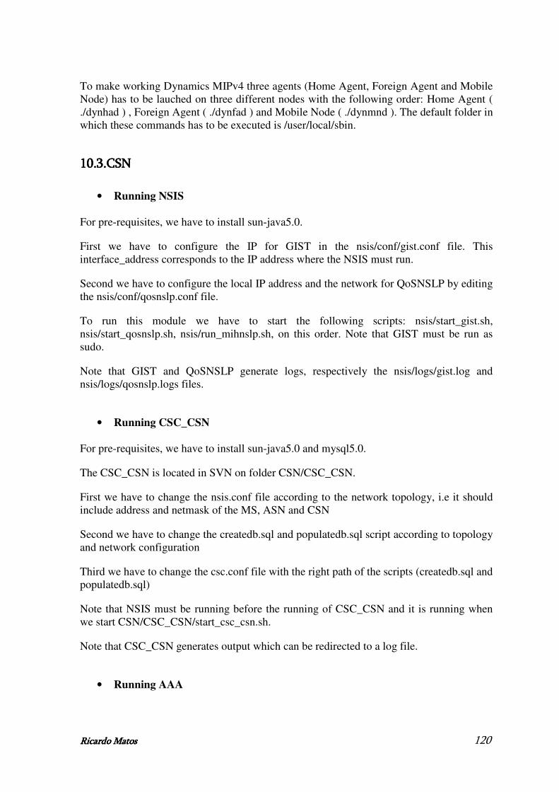
Ricardo MatoRicardo MatoRicardo MatoRicardo Matossss 120
To make working Dynamics MIPv4 three agents (Home Agent, Foreign Agent and Mobile Node) has to be lauched on three different nodes with the following order: Home Agent ( ./dynhad ) , Foreign Agent ( ./dynfad ) and Mobile Node ( ./dynmnd ). The default folder in which these commands has to be executed is /user/local/sbin.
10.3.10.3.10.3.10.3.CSNCSNCSNCSN
• Running NSIS
For pre-requisites, we have to install sun-java5.0.
First we have to configure the IP for GIST in the nsis/conf/gist.conf file. This interface_address corresponds to the IP address where the NSIS must run.
Second we have to configure the local IP address and the network for QoSNSLP by editing the nsis/conf/qosnslp.conf file.
To run this module we have to start the following scripts: nsis/start_gist.sh, nsis/start_qosnslp.sh, nsis/run_mihnslp.sh, on this order. Note that GIST must be run as sudo.
Note that GIST and QoSNSLP generate logs, respectively the nsis/logs/gist.log and nsis/logs/qosnslp.logs files.
• Running CSC_CSN
For pre-requisites, we have to install sun-java5.0 and mysql5.0.
The CSC_CSN is located in SVN on folder CSN/CSC_CSN.
First we have to change the nsis.conf file according to the network topology, i.e it should include address and netmask of the MS, ASN and CSN
Second we have to change the createdb.sql and populatedb.sql script according to topology and network configuration
Third we have to change the csc.conf file with the right path of the scripts (createdb.sql and populatedb.sql)
Note that NSIS must be running before the running of CSC_CSN and it is running when we start CSN/CSC_CSN/start_csc_csn.sh.
Note that CSC_CSN generates output which can be redirected to a log file.
• Running AAA

Ricardo MatoRicardo MatoRicardo MatoRicardo Matossss 121
For pre-requisites, we have to install sun-java5.0 and mysql5.0.
The AAA is located in SVN on folder AAA.
The AAA database can be created and populated by running the AAA/AAA_DB/create_aaaDB.sql script with a mysql command.
The AAA Server can be configured by setting some parameters into the configuration files having an XML format. These files are included in the folder AAA/conf.
o server_JDiameter.xml – Diameter Server Configuration
1. The IP address of the AAA Server has to be indicated both in the tag “transport_mngt, identity” and in “peer_table, peer1, hostname”.
2. The realm related to the AAA Server has to be indicated both in the tag “route_table, route1, realm” and in “route_table, default_route, realm”.
o client_JDiameter.xml – Diameter Client Configuration
1. The IP address of the AAA Server has to be indicated both in the tag “transport_mngt, identity” and in “peer_table, peer1, hostname”.
2. The realm related to the AAA Server has to be indicated both in the tag “route_table, route1, realm” and in “route_table, default_route, realm”.
o relay_RRTable.xml - Relay Agent Configuration
1. The realm related to the foreign AAA Server has to be indicated in the tag “record, realm_name” (e.g. 192.168.4.2, weird2.org)
2. The ‘security_id’ parameter related to the foreign AAA Server has to be indicated in the tag “record, security_id”. The format of this parameter is: ‘IP_Address, Port Number, Transport Layer’.
o AAAConfiguration.xml – AAA database connection configuration
1. The AAA Server has to be configured to be connected to the AAA database. The values of the tag “db, users”, “db, pwd”, “db, host” have to be updated with the username, password and IP address of the AAA database.
Note that AAA is running when we start AAA/start_aaaServer.sh.
AAA generate logs, respectively the aaa/bin/logs/aaa.log and aaa/bin/logs/aaa_verbose.log files.
10.4.10.4.10.4.10.4.ASNASNASNASN
• Running NSIS

Ricardo MatoRicardo MatoRicardo MatoRicardo Matossss 122
For pre-requisites, we have to install sun-java5.0.
First we have to configure the IP for GIST in the nsis/conf/gist.conf file. This interface_address corresponds to the IP address where the NSIS must run.
Second we have to configure the local IP address and the network for QoSNSLP by editing the nsis/conf/qosnslp.conf file.
Next we have to configure the nsis/conf/mihnslp.conf file with the IP addresses of MIHF’s and the communication ports.
To run this module we have to start the following scripts: nsis/start_gist.sh, nsis/start_qosnslp.sh, nsis/start_nsisatt.sh, nsis/run_mihnslp.sh, on this order. Note that GIST must be run as sudo.
Note that GIST and QoSNSLP generate logs, respectively the nsis/logs/gist.log and nsis/logs/qosnslp.logs files.
• Running MIHF
First we have to open the MIHF/MIHF.cfg file and fill with the neighbour MIHFs, as well as with the LLA and MIHU’s information.
Second we have to compile the MIHF using the makefile located on folder MIHF.
Next we have to just type on a Linux Terminal the following “./main”.
Note that NSIS must be started before the running of MIHF.
• Running CSC_ASN
For pre-requisites, we have to install sun-java5.0 and mysql5.0.
First we have to configure the file CSC_ASN/conf/client_JDiameter.xml with the IP Address of the AAAServer (CSN) and the AAAAtendant (ASN).
Second we have to change populateDB.sql file accordingly with our network configuration.
Next we have to configure the options in the CSC_ASN/csc.conf file. Note that NSIS and MIHF must be started before the running of CSC_MS and it is running when we start CSC_ASN/start_csc_asn.sh.
Note that CSC_CSN generates output which can be redirected to a log file.
• Running RC

Ricardo MatoRicardo MatoRicardo MatoRicardo Matossss 123
First we have to open the ASN_GW/RC/WIMAX_topology.cfg file and write the CSC_ASN IPv4 address, as well as the WiMAX network topology (Base Station and Subscriber Stations MAC/IPv4 addresses).
Second we have to compile the RC using the makefile located on folder ASN_GW/RC.
Next we have to just type on a Linux Terminal the following “./rc”.
Note that CSC_ASN must be started before the running of RC.
• Running Generic Adapter
The Generic Adapter is located in SVN on folder ASN_GW/Adapter/ Generic_Adapter/.
First we have to check the configurations from GASAI.h file to confirm that the IP and port numbers are correctly set for GASAI interface.
Second we have to set MAX_VENDOR_ADAPTERS [1/2/3/4] corresponding to the amount of VSAs to be connected to the Generic Adapter..
Next we have to just type on a Linux Terminal the following : ./generic_adapter [rc=0/1] [mih=0/1] [cnms= 0/1] [gasai=0/1].
Note that RC and MIHF must be started before the running of Generic Adapter.
GA will wait until the amount of MAX_VENDOR_ADAPTERS VSAs have sent their GASAI setup messages. After that the GA delivers the GASAI setup acknowledgement message to each VSA.When wanted enable the debug printouts with DEBUG flag.
• Running Redline Adapter
The Redline Adapter is located in SVN on folder ASN_GW/Adapter/ Redline_Adapter/.
Next we have to just type on a Linux Terminal the following : ./RedlineAdapter GenericAddr BsAddr TrapReceiverAddr TrapReceiverPort.
Note that Generic Adapter must be started before the running of Redline Adapter.
• Running Home Agent
Dynamics Mobile IPv4 release includes different files explaining the operations necessary to make working the software. These files can be found in the folder dynamics-0.8.1 and dynamics-0.8.1/doc (e.g. INSTALL, README, Dynamics-HUT-Mobile-IP-HOWTO)
The pre-requisites to install Dynamic MIPv4 are described in the file README into the folder dynamics-0.8.1. They can be classified in: Kernel requirements, Hardware requirements and Software requirements.

Ricardo MatoRicardo MatoRicardo MatoRicardo Matossss 124
Dynamics MIPv4 has been tested in WEIRD by using the Linux release called Ubuntu. This operating system requires the installation of some libraries to compile the software. They are named: libgmp3-dev, libgmp3c2, libc6-dev, texinfo, automake and autoconf.
We have to install the libraries necessary to compile Dynamics MIPv4, compile the software and configure the Mobile Node Agent considering the network configuration. The compilation can be performed by using the following commands:
- ./configure - make - make install
from the folder dynamics-0.8.1.
The Home Agent has to be configured using the tools provided by Dynamics MIPv4. These tools are automatically generated after the compilation of the software into the folders /user/local/sbin (./dynamics-ha-setup) and /user/local/etc ( dynhad.conf).
To make working Dynamics MIPv4 three agents (Home Agent, Foreign Agent and Mobile Node) has to be lauched on three different nodes with the following order: Home Agent ( ./dynhad ) , Foreign Agent ( ./dynfad ) and Mobile Node ( ./dynmnd ). The default folder in which these commands has to be executed is /user/local/sbin.
10.5.10.5.10.5.10.5.APAPAPAP
• Running Foreign Agent
Dynamics Mobile IPv4 release includes different files explaining the operations necessary to make working the software. These files can be found in the folder dynamics-0.8.1 and dynamics-0.8.1/doc (e.g. INSTALL, README, Dynamics-HUT-Mobile-IP-HOWTO)
The pre-requisites to install Dynamic MIPv4 are described in the file README into the folder dynamics-0.8.1. They can be classified in: Kernel requirements, Hardware requirements and Software requirements.
Dynamics MIPv4 has been tested in WEIRD by using the Linux release called Ubuntu. This operating system requires the installation of some libraries to compile the software. They are named: libgmp3-dev, libgmp3c2, libc6-dev, texinfo, automake and autoconf.
We have to install the libraries necessary to compile Dynamics MIPv4, compile the software and configure the Mobile Node Agent considering the network configuration. The compilation can be performed by using the following commands:
Ricardo MatoRicardo MatoRicardo MatoRicardo Matossss 125
- ./configure - make - make install
from the folder dynamics-0.8.1.
The Home Agent has to be configured using the tools provided by Dynamics MIPv4. These tools are automatically generated after the compilation of the software into the folders /user/local/sbin (./dynamics-fa-setup) and /user/local/etc ( dynfad.conf).
To make working Dynamics MIPv4 three agents (Home Agent, Foreign Agent and Mobile Node) has to be lauched on three different nodes with the following order: Home Agent ( ./dynhad ) , Foreign Agent ( ./dynfad ) and Mobile Node ( ./dynmnd ). The default folder in which these commands has to be executed is /user/local/sbin.
10.6.10.6.10.6.10.6.Important informationImportant informationImportant informationImportant information
All modules of the WEIRD architecture, necessaries for the testbed running, and described so far, are available in folders on the server SVN. These folders are: CSC_MS, weird_agent, LowLevelAgent, nsis, MIHF, CSC_ASN, ASN_GW/RC, ASN_GW/Adapter/Generic_Adapter, ASN_GW/Adapter/Redline_Adapter, dynamics-0.8.1. If there is a problem with any script, open it and make “set ff=unix”.

Ricardo MatoRicardo MatoRicardo MatoRicardo Matossss 126
11.11.11.11.Annex 3 Annex 3 Annex 3 Annex 3 –––– MI MI MI MIHF ImplementationHF ImplementationHF ImplementationHF Implementation
This chapter resumes the detailed information necessary to MIHF implementation.
11.1.11.1.11.1.11.1. MessagesMessagesMessagesMessages sent by LLC sent by LLC sent by LLC sent by LLC
• Link_Up message
2:1:3:13:25:19:0:0:0:0:8:0:6:0:23:49:199:143:70:0:0:8:0:6:0:19:96:132:210:48:16:9:8:0:6:0:12:41:39:141:247
2 (SID: Event service)
1 (MIH_Link_up)
3 (Operation code: Indication)
13 (Link Identifier)
25 (Length of Link Identifier)
Link-ID
19:0:0:0 (Link type)
0 (Choice Link Address -> MAC address)
8 (Length of Link Address)
0:6 (Mac Address family)
0:23:49:199:143:70 (MAC address of the interface)
Choice
0 (Choice PoA Address) (if 1 -> no PoA address)
0 (Choice Link Address -> MAC address)
8 (Length of Link Address)
0:6 (Mac Address family)
0:19:96:132:210:48 (MAC address of the PoA)
16 (Mac new Access Router)
9 (Length of Acces router address)
8 (Length of Link Address)
0:6 (Mac Address family)
0:12:41:39:141:247 (Access Router MAC)
Table Table Table Table 18181818 ---- LLC Link_U LLC Link_U LLC Link_U LLC Link_Up messagep messagep messagep message
• Link_Down message

Ricardo MatoRicardo MatoRicardo MatoRicardo Matossss 127
2:2:3:13:15:19:0:0:0:0:8:0:6:0:23:49:199:143:70:1:20:1:0
2 (SID: Event service)
2 (MIH_Link_down)
3 (Operation code: Indication)
13 (Link Identifier)
15 (Length of Link Identifier)
19:0:0:0 (Link type)
0 (Choice Link Address -> MAC address)
8 (Length of Link Address)
0:6 (Mac Address family)
0:23:49:199:143:70 (MAC address of the interface)
1 (Choice -> no PoA address in message)
20 (Link down reason code)
1 (Length)
0 (Reason: no resource)
Table Table Table Table 19191919 ---- LLC Link_DLLC Link_DLLC Link_DLLC Link_Down messageown messageown messageown message
• Link_Going_Down
2:3:3:13:25:19:0:0:0:0:8:0:6:0:23:49:199:143:70:0:0:8:0:6:0:19:96:132:210:48:21:2:50:0:22:1:20:23:1:1:24:2:1:0
2 (SID: Event service)
3 (MIH_Link_going_down)
3 (Operation code: Indication)
13 (Link Identifier)
25 (Length of Link Identifier)
19:0:0:0 (Link type)
0 (Choice Link Address -> MAC address)
8 (Length of Link Address)
0:6 (Mac Address family)
0:23:49:199:143:70 (MAC address of the interface)
0 (Choice PoA Address) (if 1 -> no PoA address)
0 (Choice Link Address -> MAC address)
8 (Length of Link Address)
0:6 (Mac Address family)
0:19:96:132:210:48 (MAC address of the PoA)
21 (Time interval)
2 (Length)
50:0 (50 in network byte order)
22 (Confidence level)
1 (Length)
20 (Value in percents)
23 (Link going down reason)
1 (Length)
1 (Reason: link parameter degrading)
24 (Unique event identifier)
2 (Length)
1:0 (1 in network byte order)
Table Table Table Table 20202020 ---- LLC Link_Going_D LLC Link_Going_D LLC Link_Going_D LLC Link_Going_Down messageown messageown messageown message

Ricardo MatoRicardo MatoRicardo MatoRicardo Matossss 128
11.2.11.2.11.2.11.2.NSIS MoNSIS MoNSIS MoNSIS Mobility NSLPbility NSLPbility NSLPbility NSLP
Figure 90 shows an example of the NSIS usage to transport MIH Messages [5]. It presents the interaction between the MIHF and the NSIS framework and the transport of MIH Messages between a Source and a Destination MIHF. In this scenario, the Middle MIHF also intervenes by receiving the message exchanged due to the intercept NSIS feature.
Figure Figure Figure Figure 90909090 ---- NSIS usage to transport MIH Messages NSIS usage to transport MIH Messages NSIS usage to transport MIH Messages NSIS usage to transport MIH Messages
To be able to transport the MIH Messages, NSIS requires the destination network address of the MIHF Destination. However, MIH entities only handle MIHF Identifiers (ID) to identify the remote MIHF. Therefore, there is the need to perform the mapping between the MIHF ID and the correspondent network addresses, which is under NSIS responsibility.
One of the MIH NSLP functionalities is to handle the mapping between MIHF ID and network addresses, since GIST is able to provide all the required functionalities required by the MIH specification for MIH Message transport. This functionality is currently being performed through the usage of a configuration file.
Figure 91 shows the procedure to send MIH Messages to the remote MIHF when the remote MIHF IP Address is available, either through the cache mechanisms or resorting to the mapping procedure.
Figure Figure Figure Figure 91919191 ---- Message transport between two MIH NSLP Message transport between two MIH NSLP Message transport between two MIH NSLP Message transport between two MIH NSLP
In this figure the MIHF Message needs to be sent from the Source MIH NSLP to the Destination MIH NSLP. To send the MIHF Message, the MIH NSLP creates a MIH NSLP DATA message with the MIHF Message as one of its components.
During the message exchange, the DATA message is intercepted in the Middle MIHF. After the Middle MIHF message processing the MIH NSLP must forward the DATA message to the Destination MIH NSLP.

Ricardo MatoRicardo MatoRicardo MatoRicardo Matossss 129
When a DATA message reaches the destination, the MIHF Message is forwarded to the local MIHF for processing. The MIH Message information is transparent to the MIH NSLP. The MIHF processing is defined in the IEEE 802.21 Draft Standard for Media Independent Handover Services.
Optionally, a DATA ACK message can be sent to the Source MIH NSLP when the DATA message arrives to the Destination MIH NSLP. This feature can be requested by the Source MIH NSLP and should depend on the transfer attributes requested to GIST (reliable and/or secure).
A MIHF response to the received MIH Message is treated as a new request by the MIH NSLP. The MIH NSLP does not handle states for the MIH Messages.
11.3.11.3.11.3.11.3.MIHF PrimitMIHF PrimitMIHF PrimitMIHF Primitivesivesivesives
11.3.1.11.3.1.11.3.1.11.3.1.MIHF_LINK_SAP InterfaceMIHF_LINK_SAP InterfaceMIHF_LINK_SAP InterfaceMIHF_LINK_SAP Interface
• Link_Up.indication
Table 21 describes the Link_Up.indication primitive parameters. Source
Module
Destination
Module
Parameter Name Parameter Type Parameter Description
Link Identifier LINK_TUPLE_ID Identifier of the link associated with the event
MAC Old Access Router
MAC_ADDRESS (Optional) MAC Address of old Access Router
MAC New Access Router
MAC_ADDRESS (Optional) MAC Address of new Access Router
IP Renewal Flag IP_RENEWAL_FLAG (Optional) Indicates whether the MN shall change IP Address in the new PoA
LLC MIHF
Mobility Management Support
IP_MOBILITY_MGMT (Optional) Indicates the type of Mobility Management protocol supported by the new PoA
Table Table Table Table 21212121 ---- Link_Up.indication primitive parameters Link_Up.indication primitive parameters Link_Up.indication primitive parameters Link_Up.indication primitive parameters
• Link_Down.indication
Table 22 describes the Link_Down.indication primitive parameters. Source
Module
Destination
Module
Parameter Name Parameter Type Parameter Description
Link Identifier LINK_TUPLE_ID Identifier of the link associated with the event
MAC Old Access Router
MAC_ADDRESS (Optional) MAC Address of old Access Router
LLC MIHF
Reason Code LINK_DOWN_REASON Reason why the link went down
Table Table Table Table 22222222 ---- Link_Down.indication primitive parameter Link_Down.indication primitive parameter Link_Down.indication primitive parameter Link_Down.indication primitive parameter

Ricardo MatoRicardo MatoRicardo MatoRicardo Matossss 130
• Link_Going_Down.indication
Table 23 describes the Link_Going_Down.indication primitive parameters. Source
Module
Destination
Module
Parameter
Name
Parameter Type Parameter Description
Link Identifier LINK_TUPLE_ID Identifier of the link associated with the event
Time Interval UNSIGNED_INT(2) Time interval (in milliseconds) in which the link is expected to go down. The link connectivity is expected to be available at least for the time specified
Confidence Level
PERCENTAGE The confidence level (%) for link to go down within the specified time interval
Link Going Down Reason
LINK_GOING_DOWN_REASON
The reason why the link is going to be down
LLC MIHF
Unique Event Identifier
UNSIGNED_INT(2) Used to uniquely identify the event. To be used in case of event rollback
Table Table Table Table 23232323 ---- Link_Going_Down.indication primitive parameters Link_Going_Down.indication primitive parameters Link_Going_Down.indication primitive parameters Link_Going_Down.indication primitive parameters
• Link_Action.request
Table 24 describes the Link_Action.request primitive parameters. Source
Module
Destination
Module
Parameter
Name
Parameter Type Parameter Description
PoAMACAddress
MAC_ADDRESS (Optional) The PoA MAC address is included when the DATA_FORWARDING_REQUEST action is requested
LinkAction LINK_ACTION Specifies the suggested action
MIHF LLC ExecutionDelay
UNSIGNED_INT(2)
Time (in ms) to elapse before the action needs to be taken. A value of 0 indicates that the action shall be taken immediately. Time elapsed shall be calculated from the instance the request arrives until the time when the execution of the action is carried out
Table Table Table Table 24242424 ---- Link_Action.request primitive parameters Link_Action.request primitive parameters Link_Action.request primitive parameters Link_Action.request primitive parameters
11.3.2.11.3.2.11.3.2.11.3.2.MIHF_NET_SAP InterfaceMIHF_NET_SAP InterfaceMIHF_NET_SAP InterfaceMIHF_NET_SAP Interface
• MIH_Register.request
Table 25 describes the MIH_Register request message parameters.

Ricardo MatoRicardo MatoRicardo MatoRicardo Matossss 131
Source
Module
Destination
Module
Parameter Name Parameter Type Parameter Description
Source Identifier MIHF_ID This identifies the local MIHF which is the source of this request
Destination Identifier
MIHF_ID This identifies a remote MIHF which will be the destination of this request
MIHF MIHF RequestCode REG_REQUEST_CODE
Registration request code. Depending on the request code, the MIH User can choose to either register or re-register with the local or remote MIHF
Table Table Table Table 25252525 ---- MIH_Register.request primitive parameters MIH_Register.request primitive parameters MIH_Register.request primitive parameters MIH_Register.request primitive parameters
• MIH_Register.response
Table 26 describes the MIH_Register response message parameters. Source
Module
Destination
Module
Parameter
Name
Parameter Type Parameter Description
Source Identifier
MIHF_ID This identifies the local MIHF which is the source of this response
Destination Identifier
MIHF_ID This identifies a remote MIHF which will be the destination of this response
Valid Time Interval
UNSIGNED_INT(4) Time interval in seconds during which the registration is valid. Parameter applicable only when the status parameter indicates a successful operation. A value of 0 indicates an infinite validity period.
MIHF MIHF
Status STATUS Status of operation
Table Table Table Table 26262626 ---- MIH_Register.response primitive parameters MIH_Register.response primitive parameters MIH_Register.response primitive parameters MIH_Register.response primitive parameters
• MIH_Event_Subscribe.request
Table 27 describes the MIH_Event_Subscribe request message parameters. Source
Module
Destination
Module
Parameter
Name
Parameter Type Parameter Description
Source Identifier
MIHF_ID This identifies the local MIHF which is the source of this request
Destination Identifier
MIHF_ID This identifies a remote MIHF which will be the destination of this request
Link Identifier LINK_TUPLE_ID Identifier of the link for event subscription. For local event subscription, PoA link address need not be present if the link type lacks such a value
MIHF MIHF
Requested MIH Event List
MIH_EVENT_LIST List of MIH events that the endpoint would like to receive indications for, from the Event Source
Table Table Table Table 27272727 ---- MIH_Event_Subscribe.request primitive parameters MIH_Event_Subscribe.request primitive parameters MIH_Event_Subscribe.request primitive parameters MIH_Event_Subscribe.request primitive parameters
• MIH_Event_Subscribe.response
Table 28 describes the MIH_Event_Subscribe response message parameters.

Ricardo MatoRicardo MatoRicardo MatoRicardo Matossss 132
Source
Module
Destination
Module
Parameter
Name
Parameter Type Parameter Description
Source Identifier MIHF_ID This identifies the local MIHF which is the source of this response
Destination Identifier
MIHF_ID This identifies a remote MIHF which will be the destination of this response
Link Identifier LINK_TUPLE_ID Identifier of the link for the event subscription
Response MIH Event List
MIH_EVENT_LIST List of MIH events.
MIHF MIHF
Status STATUS Status of the operation.
Table Table Table Table 28282828 ---- MIH_Event_Subscribe.response primitive parameters MIH_Event_Subscribe.response primitive parameters MIH_Event_Subscribe.response primitive parameters MIH_Event_Subscribe.response primitive parameters
• MIH_Link_Up.indication
Table 29 describes the MIH_Link_Up indication message parameters. Source
Module
Destination
Module
Parameter
Name
Parameter Type Parameter Description
Source Identifier MIHF_ID This identifies the local MIHF which is the source of this indication
Destination Identifier
MIHF_ID This identifies a remote MIHF which will be the destination of this indication.
Link Identifier LINK_TUPLE_ID Identifier of the link associated with the event.
Mac Old Access Router
MAC_ADDRESS (Optional) MAC Address of old Access Router
Mac New Access Router
MAC_ADDRESS (Optional) MAC Address of new Access Router
IP Renewal Flag IP_RENEWAL_FLAG (Optional) Indicates whether the MN shall change IP Address in the new PoA
MIHF MIHF
Mobility Management Support
IP_MOBILITY_MGMT (Optional) Indicates the type of Mobility Management protocol supported by the new PoA
Table Table Table Table 29292929 ---- MIH_Link_Up.indication primitive parameters MIH_Link_Up.indication primitive parameters MIH_Link_Up.indication primitive parameters MIH_Link_Up.indication primitive parameters
• MIH_Link_Down.indication
Table 30 describes the MIH_Link_Down indication message parameters.

Ricardo MatoRicardo MatoRicardo MatoRicardo Matossss 133
Source
Module
Destination
Module
Parameter
Name
Parameter Type Parameter Description
Source Identifier
MIHF_ID This identifies the local MIHF which is the source of this indication
Destination Identifier
MIHF_ID This identifies a remote MIHF which will be the destination of this indication
Link Identifier LINK_TUPLE_ID Identifier of the link associated with the event
Mac Old Access Router
MAC_ADDRESS (Optional) MAC Address of old Access Router
MIHF MIHF
Reason Code LINK_DOWN_REASON_CODE
Reason why the link went down
Table Table Table Table 30303030 ---- MIH_MIH_MIH_MIH_Link_Down.indication primitiveLink_Down.indication primitiveLink_Down.indication primitiveLink_Down.indication primitive parameters parameters parameters parameters
• MIH_Link_Going_Down.indication
Table 31 describes the MIH_Link_Going_Down indication message parameters. Source
Module
Destination
Module
Parameter Name Parameter Type Parameter Description
Source Identifier MIHF_ID This identifies the local MIHF which is the source of this indication
Destination Identifier
MIHF_ID This identifies a remote MIHF which will be the destination of this indication
Link Identifier LINK_TUPLE_ID Identifier of the link associated with the event
Time Interval UNSIGNED_INT(2) Time Interval (in milliseconds) specifies the time interval in which the link is expected to go down. The link connectivity is expected to be available at least for the time specified
Confidence Level PERCENTAGE The confidence level (%) for link to go down within the specified time interval
Link Going Down Reason
LINK_GOING_DOWN_REASON
The reason why the link is going down
MIHF MIHF
Unique Event Identifier
UNSIGNED_INT(2) Used to uniquely identify the event. To be used in case of event rollback
Table Table Table Table 31313131 ---- MIH_Link_ MIH_Link_ MIH_Link_ MIH_Link_Going_Down.indication primitiveGoing_Down.indication primitiveGoing_Down.indication primitiveGoing_Down.indication primitive parameters parameters parameters parameters
• MIH_Get_Information.request
Table 32 describes the MIH_Get_Information.request message parameters.

Ricardo MatoRicardo MatoRicardo MatoRicardo Matossss 134
Source
Module
Destination
Module
Parameter
Name
Parameter Type Parameter Description
Source Identifier
MIHF_ID This identifies the local MIHF which is the source of this indication
Destination Identifier
MIHF_ID This identifies a remote MIHF which will be the destination of this indication
InfoQueryBinaryDataList
LIST(INFO_QUERY_BINA RY_DATA)
(Optional) A list of binary queries. The order of the queries in the list identifies the priority of the query. The first query has the highest priority to be processed by MIIS
InfoQueryRDFDataList
LIST(INFO_QUERY_RDF_ DATA)
(Optional) A list of RDF queries. The order of the queries in the list identifies the priority of the query. The first query has the highest priority to be processed by MIIS
InfoQueryRDFSchemaURL
NULL (Optional) An RDF Schema URL query
InfoQueryRDFSchemaList
LIST(INFO_QUERY_RDF_ SCHEMA)
(Optional) A list of RDF schema queries. The order of the queries in the list identifies the priority of the query. The first query has the highest priority to be processed by MIIS
MIHF MIHF
MaxResponseSize
UNSIGNED_INT(2)
(Optional) This field specifies the maximum size of Info Response parameters (i.e., Info Response Binary Data List, Info Response RDF Data List, Info Response RDF Schema URL and Info Response RDF Schema List) in MIH_Get_Information response primitive in octets. If this field is not specified, the maximum size is set to 65,535. The actual maximum size forced by the IS server may be smaller than that specified by the IS client
Table Table Table Table 32323232 ---- MIH_Get MIH_Get MIH_Get MIH_Get_Information.reque_Information.reque_Information.reque_Information.request primitive st primitive st primitive st primitive parametersparametersparametersparameters
• MIH_Get_Information.response
Table 33 describes the MIH_Get_Information.response message parameters.

Ricardo MatoRicardo MatoRicardo MatoRicardo Matossss 135
Source
Module
Destination
Module
Parameter
Name
Parameter Type Parameter Description
Source Identifier
MIHF_ID This identifies the local MIHF which is the source of this indication
Destination Identifier
MIHF_ID This identifies a remote MIHF which will be the destination of this indication.
InfoResponseBinaryDataList
LIST(INFO_RSP_BINARY_ DATA)
(Optional) A list of binary query responses. The list may be sorted from most preferred first to least preferred last
InfoResponseRDFDataList
LIST(INFO_RSP_RDF_DAT A)
(Optional) A list of RDF query responses. The list may be sorted from most preferred first to least preferred last
InfoResponseRDFSchemaURLList
LIST(INFO_RSP_RDF_URL )
(Optional) A list of RDF Schema URL. The list may be sorted from most preferred first to least preferred last
InfoResponseRDFSchemaList
LIST(INFO_RSP_RDF_SCH EMA)
(Optional) A list of RDF schema query responses. The list may be sorted from most preferred first to least preferred last
MIHF MIHF
Status STATUS Status of operation.The response lists contains meaningful data if and only if the status is ‘0’
Table Table Table Table 33333333 ---- MIH_Get MIH_Get MIH_Get MIH_Get_Information.response primitive_Information.response primitive_Information.response primitive_Information.response primitive parameters parameters parameters parameters
• MIH_ Link_Action.request
Table 34 describes the MIH_Link_Action.request primitive parameters. Source
Module
Destination
Module
Parameter
Name
Parameter Type Parameter Description
Source Identifier
MIHF_ID This identifies the local MIHF which is the source of this indication
Destination Identifier
MIHF_ID This identifies a remote MIHF which will be the destination of this indication MIHF MIHF
Link Actions List
LINK_ACTION_REQ Specifies the suggested actions
Table Table Table Table 34343434 ---- MIH_Link_Action.request primitive parameters MIH_Link_Action.request primitive parameters MIH_Link_Action.request primitive parameters MIH_Link_Action.request primitive parameters
11.3.3.11.3.3.11.3.3.11.3.3.MIH_SAP InterfaceMIH_SAP InterfaceMIH_SAP InterfaceMIH_SAP Interface
• MIH_Register.request
Table 35 describes the MIH_Register.request primitive parameters. Source
Module
Destination
Module
Parameter
Name
Parameter Type Parameter Description
Destination Identifier
MIHF_ID This identifies the local MIHF or a remote MIHF which will be the destination of this request
MIHU MIHF Request Code REG_REQUEST_CODE Registration request code. Depending on the request code, the MIH User can choose to either register or re-register with the local or remote MIHF
Table Table Table Table 35353535 ---- MIH_Regis MIH_Regis MIH_Regis MIH_Register.request primitive parameterster.request primitive parameterster.request primitive parameterster.request primitive parameters

Ricardo MatoRicardo MatoRicardo MatoRicardo Matossss 136
• MIH_Register.confirm
Table 36 describes the MIH_Register.confirm primitive parameters. Source
Module
Destination
Module
Parameter
Name
Parameter Type Parameter Description
Source Identifier
MIHF_ID This identifies the invoker of this primitive which is a remote MIHF
Valid Time Interval
UNSIGNED_INT(4) Time interval in seconds during which the registration is valid. Parameter applicable only when the status parameter indicates a successful operation. A value of 0 indicates an infinite validity period
MIHF MIHU
Status STATUS Status of operation
Table Table Table Table 36363636 ---- MIH_Register.confirm primitive parameters MIH_Register.confirm primitive parameters MIH_Register.confirm primitive parameters MIH_Register.confirm primitive parameters
• MIH_Event_Subscribe.request
Table 37 describes the MIH_Event_Subscribe.request primitive parameters. Source
Module
Destination
Module
Parameter
Name
Parameter Type Parameter Description
Destination Identifier
MIHF_ID This identifies the local MIHF or a remote MIHF which will be the destination of this request
Link Identifier LINK_TUPLE_ID Identifier of the link for event subscription. For local event subscription, PoA link address need not be present if the link type lacks such a value
MM/GUI MIHF
Requested MIH Event List
MIH_EVENT_LIST List of MIH events that the endpoint would like to receive indications for, from the Event Source
Table Table Table Table 37373737 ---- MIH_Event_Subscribe.request primitive parameters MIH_Event_Subscribe.request primitive parameters MIH_Event_Subscribe.request primitive parameters MIH_Event_Subscribe.request primitive parameters
• MIH_Event_Subscribe.confirm
Table 38 describes the MIH_Event_Subscribe.confirm primitive parameters. Source
Module
Destination
Module
Parameter
Name
Parameter Type Parameter Description
Source Identifier
MIHF_ID This identifies the invoker of this primitive which can be either the local MIHF or a remote MIHF
Link Identifier LINK_TUPLE_ID Identifier of the link for the event subscription
Response MIH Event List
MIH_EVENT_LIST List of MIH events
MIHF MIHU
Status STATUS Status of the operation
Table Table Table Table 38383838 ---- MIH_Event_Subscribe.confirm primitive parameters MIH_Event_Subscribe.confirm primitive parameters MIH_Event_Subscribe.confirm primitive parameters MIH_Event_Subscribe.confirm primitive parameters
• MIH_Link_Up.indication
Table 39 describes the MIH_Link_Up.indication primitive parameters.

Ricardo MatoRicardo MatoRicardo MatoRicardo Matossss 137
Source
Module
Destination
Module
Parameter Name Parameter Type Parameter Description
Source Identifier MIHF_ID This identifies the invoker of this primitive which can be either the local MIHF or a remote MIHF
Link Identifier LINK_TUPLE_ID Identifier of the link associated with the event
Mac Old Access Router
MAC_ADDRESS (Optional) MAC Address of old Access Router
Mac New Access Router
MAC_ADDRESS (Optional) MAC Address of new Access Router
IP Renewal Flag IP_RENEWAL_FLAG (Optional) Indicates whether the MN shall change IP Address in the new PoA
MIHF MIHU
Mobility Management Support
IP_MOBILITY_MGMT (Optional) Indicates the type of Mobility Management protocol supported by the new PoA
Table Table Table Table 39393939 ---- MIH_Link_Up.indication primitive parameters MIH_Link_Up.indication primitive parameters MIH_Link_Up.indication primitive parameters MIH_Link_Up.indication primitive parameters
• MIH_Link_Down.indication
Table 40 describes the MIH_Link_Down.indication primitive parameters. Source
Module
Destination
Module
Parameter
Name
Parameter Type Parameter Description
Source Identifier
MIHF_ID This identifies the invoker of this primitive which can be either the local MIHF or a remote MIHF
Link Identifier LINK_TUPLE_ID Identifier of the link associated with the event
Mac Old Access Router
MAC_ADDRESS (Optional) MAC Address of old Access Router
MIHF MIHU
Reason Code LINK_DOWN_REASON_CODE
Reason why the link went down
Table Table Table Table 40404040 ---- MIH_Link_Down. MIH_Link_Down. MIH_Link_Down. MIH_Link_Down.indication primitive indication primitive indication primitive indication primitive parametersparametersparametersparameters
• MIH_Link_Going_Down.indication
Table 41 describes the MIH_Link_Going_Down.indication primitive parameters.

Ricardo MatoRicardo MatoRicardo MatoRicardo Matossss 138
Source
Module
Destination
Module
Parameter
Name
Parameter Type Parameter Description
Source Identifier
MIHF_ID This identifies the invoker of this primitive which can be either the local MIHF or a remote MIHF
Link Identifier LINK_TUPLE_ID Identifier of the link associated with the event
Time Interval UNSIGNED_INT(2) Time Interval (in milliseconds) specifies the time interval in which the link is expected to go down. The link connectivity is expected to be available at least for the time specified
Confidence Level
PERCENTAGE The confidence level (%) for link to go down within the specified time interval
Link Going Down Reason
LINK_GOING_DOWN_REASON
The reason why the link is going down
MIHF MIHU
Unique Event Identifier
UNSIGNED_INT(2) Used to uniquely identify the event. To be used in case of event rollback
Table Table Table Table 41414141 ---- MIH_Link_G MIH_Link_G MIH_Link_G MIH_Link_Going_Down.indication primitiveoing_Down.indication primitiveoing_Down.indication primitiveoing_Down.indication primitive parameters parameters parameters parameters
• MIH_Get_Information.request
Table 42 describes the MIH_Get_Information.request message parameters. Source
Module
Destination
Module
Parameter
Name
Parameter Type Parameter Description
Destination Identifier
MIHF_ID The local MIHF or a remote MIHF which will be the destination of this request
InfoQueryBinaryDataList
LIST(INFO_QUERY_BINA RY_DATA)
(Optional) A list of binary queries. The order of the queries in the list identifies the priority of the query. The first query has the highest priority to be processed by MIIS
InfoQueryRDFDataList
LIST(INFO_QUERY_RDF_ DATA)
(Optional) A list of RDF queries. The order of the queries in the list identifies the priority of the query. The first query has the highest priority to be processed by MIIS
InfoQueryRDFSchemaURL
NULL (Optional) An RDF Schema URL query.
InfoQueryRDFSchemaList
LIST(INFO_QUERY_RDF_ SCHEMA)
(Optional) A list of RDF schema queries. The order of the queries in the list identifies the priority of the query. The first query has the highest priority to be processed by MIIS
MIHU MIHF
MaxResponseSize
UNSIGNED_INT(2)
(Optional) This field specifies the maximum size of Info Response parameters in MIH_Get_Information response primitive in octets. If this field is not specified, the maximum size is set to 65,535. The actual maximum size forced by the IS server may be smaller than that specified by the IS client
Table Table Table Table 42424242 ---- MIH_GeMIH_GeMIH_GeMIH_Get_Information.request primitivet_Information.request primitivet_Information.request primitivet_Information.request primitive parameters parameters parameters parameters
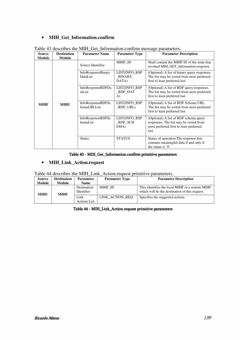
Ricardo MatoRicardo MatoRicardo MatoRicardo Matossss 139
• MIH_Get_Information.confirm
Table 43 describes the MIH_Get_Information.confirm message parameters. Source
Module
Destination
Module
Parameter Name Parameter Type Parameter Description
Source Identifier MIHF_ID Shall contain the MIHF ID of the node that
invoked MIH_GET_Information.response
InfoResponseBinaryDataList
LIST(INFO_RSP_BINARY_ DATA)
(Optional) A list of binary query responses. The list may be sorted from most preferred first to least preferred last
InfoResponseRDFDataList
LIST(INFO_RSP_RDF_DAT A)
(Optional) A list of RDF query responses. The list may be sorted from most preferred first to least preferred last
InfoResponseRDFSchemaURLList
LIST(INFO_RSP_RDF_URL)
(Optional) A list of RDF Schema URL. The list may be sorted from most preferred first to least preferred last
InfoResponseRDFSchemaList
LIST(INFO_RSP_RDF_SCH EMA)
(Optional) A list of RDF schema query responses. The list may be sorted from most preferred first to least preferred last
MIHF MIHU
Status STATUS Status of operation.The response lists contains meaningful data if and only if the status is ‘0’
Table Table Table Table 43434343 ---- MIH_Ge MIH_Ge MIH_Ge MIH_Get_Information.confirm primitivet_Information.confirm primitivet_Information.confirm primitivet_Information.confirm primitive parameters parameters parameters parameters
• MIH_Link_Action.request
Table 44 describes the MIH_Link_Action.request primitive parameters. Source
Module
Destination
Module
Parameter
Name
Parameter Type Parameter Description
Destination Identifier
MIHF_ID This identifies the local MIHF or a remote MIHF which will be the destination of this request
MIHU MIHF Link Actions List
LINK_ACTION_REQ Specifies the suggested actions
Table Table Table Table 44444444 ---- MIH_Link_Action.request primitive parameters MIH_Link_Action.request primitive parameters MIH_Link_Action.request primitive parameters MIH_Link_Action.request primitive parameters


![Módulo 2 rev - ead.senasp.gov.br · Módulo 2 – Countries and Greetings (Países e Cumprimentos) ... TEST YOURSELF: Select the correct pronoun (we, you [plural], they) for the](https://img.document.onl/doc/110x75/5b8449377f8b9aef498bfee5/modulo-2-rev-ead-modulo-2-countries-and-greetings-paises-e-cumprimentos.jpg)


![Secondary Augmentation Mastopexy to Correct …...primary problem is one of ptosis and performing augmentation mammaplasty as a second procedure [1,2]. If the primary problem is of](https://img.document.onl/doc/110x75/5e4f0316795f3a6bca096501/secondary-augmentation-mastopexy-to-correct-primary-problem-is-one-of-ptosis.jpg)


![Tubos Reunidos 2012 1a parte [Modo de compatibilidad] · 6 Core Seamless Steel Tube Manufacturing Business Production sites located in the Basque Country (Northern Spain) Wide portfolio](https://img.document.onl/doc/110x75/5bb0c58b09d3f25b308cac2a/tubos-reunidos-2012-1a-parte-modo-de-compatibilidad-6-core-seamless-steel.jpg)