Embed Size (px)
Citation preview

J. Aerosp.Technol. Manag., São José dos Campos, Vol.3, No.3, pp. 325-330, Sep. - Dec., 2011 325
Alexandre Garcia*
Institute of Aeronautics and SpaceSão José dos Campos/SP – Brazil
Sidney Servulo Cunha YamanakaInstitute of Aeronautics and SpaceSão José dos Campos/SP – Brazil
Alexandre Nogueira BarbosaInstitute of Aeronautics and SpaceSão José dos Campos/SP – Brazil
Francisco Carlos Parquet BizarriaInstitute of Aeronautics and SpaceSão José dos Campos/SP – Brazil
Wolfgang JungGerman Aerospace Center
Oberpfaffenhofen – [email protected]
Frank ScheuerpflugGerman Aerospace Center
Oberpfaffenhofen – [email protected]
* author for correspondence
VSB-30 sounding rocket: history of flight performanceAbstract: The VSB-30 vehicle is a two-stage, unguided, rail launched sounding rocket, consisting of two solid propellant motors, payload, with recovery and service system. By the end of 2010, ten vehicles had already been launched, three from Brazil (Alcântara) and seven from Sweden (Esrange). The objective of this paper is to give an overview of the main characteristics of the first ten flights of the VSB-30, with emphasis on performance and trajectory data. The circular 3σ dispersion area for payload impact point has around 50 km of radius. In most launchings of such vehicle, the impact of the payload fell within 2 sigma. This provides the possibility for further studies to decrease the area of dispersion from the impact point.Keywords: VSB-30, Sounding rocket, Trajectory, Performance.
INTRODUCTION
The VSB-30 vehicle is a two-stage, unguided, rail launched sounding rocket, consisting of a solid propellant S31 rocket booster, a boost adapter, the second stage S30, payload, a recovery and a service systems. Motor and payload are connected by an adapter section and they are separated by pneumatic pistons. The vehicle is designed to fly in a spin stabilized unguided mode. The spin stabilization is achieved by using canted fins. To reduce impact dispersion, the vehicle is equipped with three spin-up motors, installed in the booster adapter. The fins are arranged in the standard three-fin configuration and they are nominally set to 18’ (S31) and 21’ (S30), respectively, causing the vehicle to spin from lift-off through burnout. The roll rate at burnout is approximately 3.3 Hz. Total action time for the S31 is 16.0 seconds and 32.0 seconds for the S30. Both motors have a 22-inch diameter (557 mm) (Jung and Gomes, 2006).
In 1976, Germany’s national Texus sounding-rocket programme was started and it continues to the present day. Texus (Technologische Experimente unter Schwerelosigkeit)
used British Skylark seven rockets, which provided about six minutes of microgravity. Only recently, in 2005, the Skylark ceased to be commercially available, so that from Texus 42 onwards (November 2005) the Skylark Seven has been replaced by the Brazilian VSB-30 rocket, (Seibert, 2006).
In 1996, the German Aerospace Center (DLR) proposed to Comando Geral de Tecnologia Aeroespacial (DCTA) the adaptation of its Mini-TEXUS payload to the first stage of SONDA III, which had its first flight in 1976. This new single stage vehicle was known as VS-30. In 2001, the Unified Microgravity Program for Sounding Rockets proposed to DCTA the development of a boosted version of the VS-30. The challenge was accepted, and the development of the S31 booster motor started. The qualification of the motor consisted of three static firings. The maiden flight was from the Alcântara Launcher Center (CLA) in 2004, (Palmério et al., 2003).
The first operational flight from Esrange was in 2005. TEXUS is the European/German sounding rocket programme, which serves the microgravity programmes of the German Aerospace Center (DLR) and of the European Space Agency (ESA). The launches are conducted from Esrange, in Sweden.
Figure 1 shows a sequence of pictures from the time of the launch of VSB-30 V07 in 2010 from the CLA.
Received: 30/05/11 Accepted: 23/09/11
doi: 10.5028/jatm.2011. 03032211

Garcia, A. et al.
J. Aerosp.Technol. Manag., São José dos Campos, Vol.3, No.3, pp. 325-330, Sep. - Dec., 2011326
OBJECTIVES
The objective of this paper is to give an overview of the main characteristics of the first ten flights of the VSB-30, with emphasis on performance and trajectory data. After briefly delving into the history of the VSB-30 sounding rocket in the Introduction, the idea is to give a brief overview of the architecture, the sequence off light events in a typical mission, the list of flown missions, and, finally, the trajectory and flight information for each mission. The final sections of this article deal with the uncertainty in the impact point of the vehicle and the factors affecting it.
ARCHITECTURE
The basic architecture of VSB-30 is presented in Fig. 2 (Jung, 2006).
FLIGHT EVENTS
The VSB-30 flight events sequence is presented in Table 1 and Fig. 3 (Garcia, 2010).
Figure 1. VSB-30 being launched from Alcantara Launcher Center.
Table 1. Main events of flight.
Events Time (s)
Altitude (km)
Range (km)
First stage ignition 0.00 0.051 0.00Lift-off 0.45 0.056 0.00Burn-out of 1st stage / separation 13.5 3.617 0.450Ignition of 2nd stage 15.0 4.323 0.552Apogee of 1st stage 31.0 6.511 0.970Burn-out of 2nd stageNose cone ejectionYo-Yo releaseSecond stage /payload separation
44.055.056.059.0
43.164.366.171.7
7.3211.311.612.7
Impact of 1st stage 106.0 0.00 1.1Payload apogee 259.0 252.7 81.1Flight time above 100 km 368 sDrogue chute deploymentPayload impact (without parachute)
492.6497.0
6.10.00
154.7155.6
PayloadRecovery system including GPS service module, TV links, experiments, etc.
Second stagePayload adapter, separation ring, conical modules, S30 solid-propellant motor, second stage fin assembly, consisting of tail can and three fins.
First stageBoost adapter, S31 solid-propellant motor, first stage fin assembly, and tail can be equipped with three fins, spin-up motors, etc.
Figure 2. Basic architecture from VSB-30.
LIST OF CAMPAIGNS
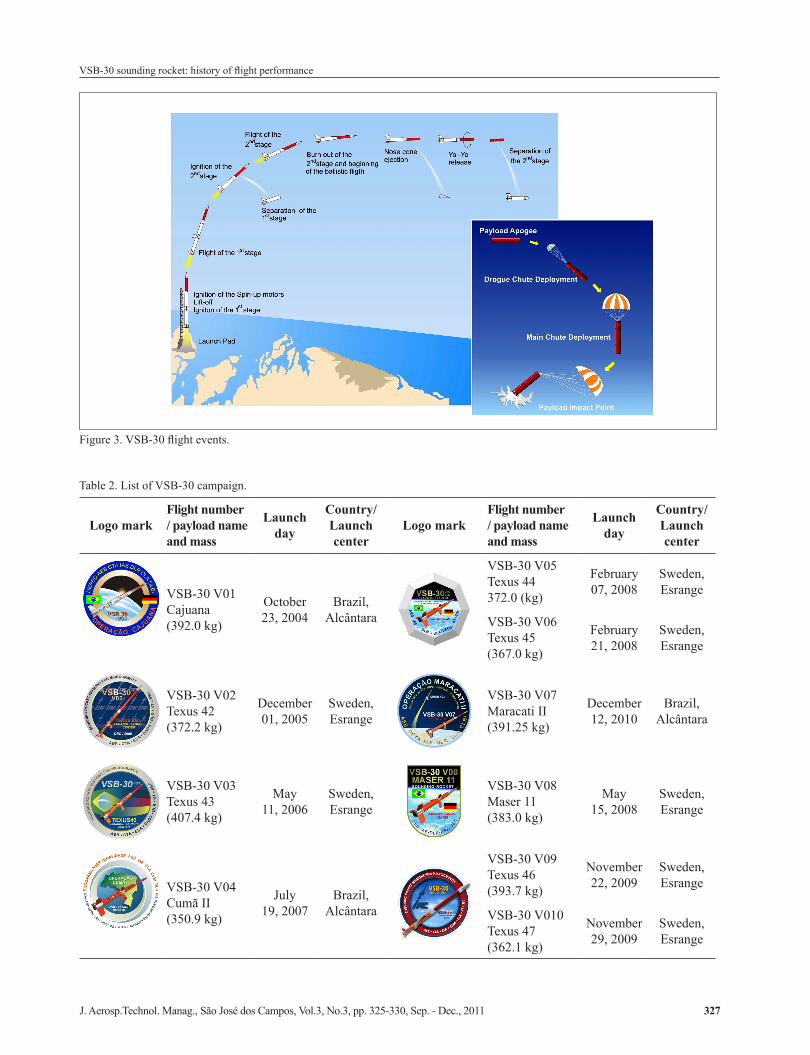
Table 2 provides the selected information about the first 10 VSB-30 campaigns.
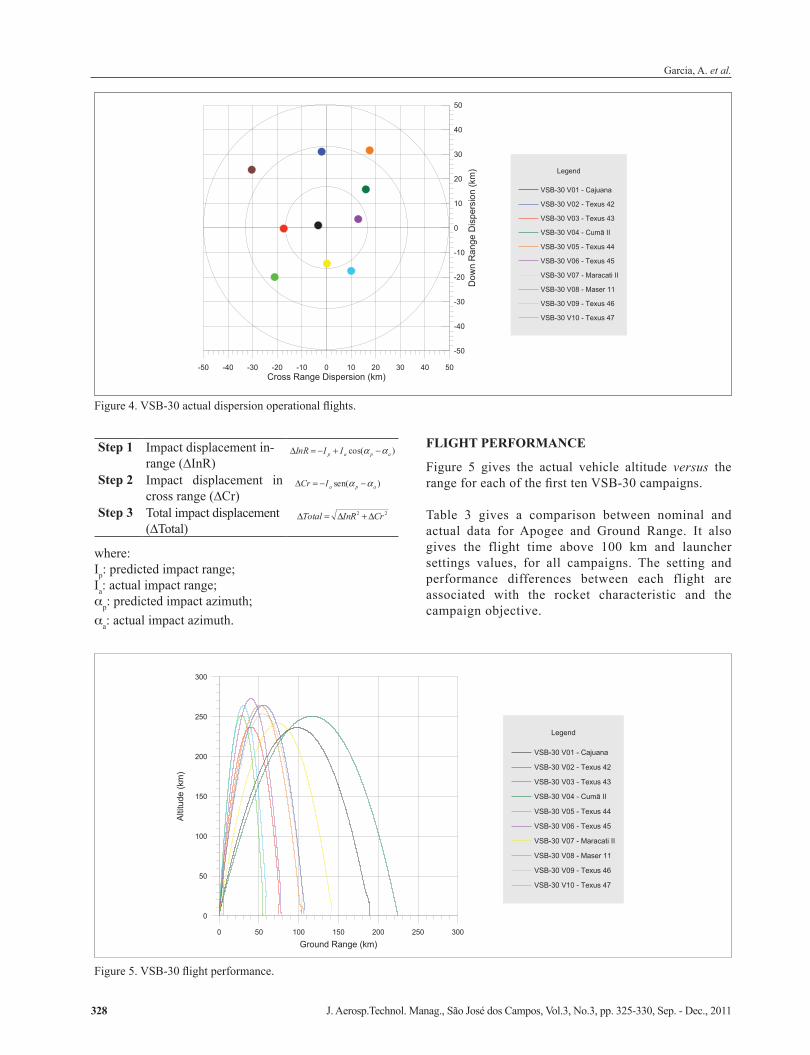
IMPACT POINT DISPLACEMENT
The impact point showed in Fig. 4 for each flight of the VSB-30 is a statistical displacement of the actual impact point from the predicted one. It is used to calculate the probability of impact within a given distance from the nominal impact point. The distance is referenced to a sigma value. For VSB-30 the radius of 3 sigma is around 50 km. The following procedure was used to determine the actual impact displacement or miss-distance for each flight (Bristol Aerospace, 1968).
VSB-30 sounding rocket: history of flight performance
J. Aerosp.Technol. Manag., São José dos Campos, Vol.3, No.3, pp. 325-330, Sep. - Dec., 2011 327
Figure 3. VSB-30 flight events.
Table 2. List of VSB-30 campaign.
Logo markFlight number / payload name and mass
Launch day
Country/ Launch center
Logo markFlight number / payload name and mass
Launch day
Country/ Launch center
VSB-30 V01Cajuana(392.0 kg)
October23, 2004
Brazil, Alcântara
VSB-30 V05Texus 44372.0 (kg)
February 07, 2008
Sweden, Esrange
VSB-30 V06Texus 45(367.0 kg)
February 21, 2008
Sweden, Esrange
VSB-30 V02Texus 42(372.2 kg)
December 01, 2005
Sweden, Esrange
VSB-30 V07Maracati II(391.25 kg)
December12, 2010
Brazil, Alcântara
VSB-30 V03Texus 43(407.4 kg)
May11, 2006
Sweden, Esrange
VSB-30 V08Maser 11(383.0 kg)
May15, 2008
Sweden, Esrange
VSB-30 V04Cumã II(350.9 kg)
July19, 2007
Brazil, Alcântara
VSB-30 V09Texus 46(393.7 kg)
November22, 2009
Sweden, Esrange
VSB-30 V010Texus 47(362.1 kg)
November29, 2009
Sweden, Esrange
Garcia, A. et al.
J. Aerosp.Technol. Manag., São José dos Campos, Vol.3, No.3, pp. 325-330, Sep. - Dec., 2011328
where: Ip: predicted impact range;Ia: actual impact range;αp: predicted impact azimuth;αa: actual impact azimuth.
FLIGHT PERFORMANCE
Figure 5 gives the actual vehicle altitude versus the range for each of the first ten VSB-30 campaigns.
Table 3 gives a comparison between nominal and actual data for Apogee and Ground Range. It also gives the flight time above 100 km and launcher settings values, for all campaigns. The setting and performance differences between each flight are associated with the rocket characteristic and the campaign objective.
-50 -40 -30 -20 -10 0 10 20 30 40 50Cross Range Dispersion (km)
-50
-40
-30
-20
-10
0
10
20
30
40
50
Dow
n R
ange
Dis
pers
ion
(km
)
VSB-30 V01 - Cajuana
Legend
VSB-30 V02 - Texus 42
VSB-30 V03 - Texus 43
VSB-30 V04 - Cumã II
VSB-30 V05 - Texus 44
VSB-30 V06 - Texus 45
VSB-30 V07 - Maracati II
VSB-30 V08 - Maser 11
VSB-30 V09 - Texus 46
VSB-30 V10 - Texus 47
Figure 4. VSB-30 actual dispersion operational flights.
0 50 100 150 200 250 300
Ground Range (km)
0
50
100
150
200
250
300
Altit
ude
(km
)
VSB-30 V01 - Cajuana
Legend
VSB-30 V02 - Texus 42
VSB-30 V03 - Texus 43
VSB-30 V04 - Cumã II
VSB-30 V05 - Texus 44
VSB-30 V06 - Texus 45
VSB-30 V07 - Maracati II
VSB-30 V08 - Maser 11
VSB-30 V09 - Texus 46
VSB-30 V10 - Texus 47
Figure 5. VSB-30 flight performance.
Step 1 Impact displacement in-range (∆InR)
)cos( apap IIInR
Step 2 Impact displacement in cross range (∆Cr)
)sen( apaICr
Step 3 Total impact displacement(∆Total)
22 CrInRTotal

VSB-30 sounding rocket: history of flight performance
J. Aerosp.Technol. Manag., São José dos Campos, Vol.3, No.3, pp. 325-330, Sep. - Dec., 2011 329
DISPERSION AREA
The rocket motions during flight are governed by a number of forces and factors: motor thrust, aerodynamic forces, gravity, wind, wind shear, atmospheric friction, decrease of the rocket mass resulting from the consumption of propellants during flight, the movement of the center of gravity during that process, and forces generated by air rudders and jet vanes (Ordway et al., 2007). The main contributors to the dispersion of impact parts of this type of rockets are manufacturing or assembly misalignments and the wind (James, 1961). Wind dispersion could be made less significant by the use of wind-compensation techniques and automations procedures to set the position of the launcher. In Brazil, the calculation of the adjustment of the azimuth and elevation angles is made for a dedicated software called “Guará” (Yamanaka and Gomes, 2001). This software needs the real-time information about direction and velocity of the wind.
The dispersion area is calculated by using rocket parameter error of mass, thrust, aerodynamic, winds, drag of parachute, launcher setting, and so on. The circular 3σ dispersion area for the VSB-30 payload has around a radius of 50 km, using the parameters error listed in Table 4. For that analysis, all perturbation factors are considered. Statistically it implied that the dispersion factors will, in more than 99% of all cases, be less than or equal to the values assumed. Impact displacements, caused by the individual factors, are then combined by the square root of the sum of the squares (of the displacements) to give a 3σ tolerance, (Scheuerpflug, 2009). We can see in Fig. 5 that all impact points for the ten VSB-30 are into the dispersion area. The mathematical method used to calculate the dispersion is the residual sum of square (RSS) by a software called TDA (Garcia and Louis, 2005).
COMMENTS AND CONCLUSIONS
The circular 3σ dispersion area from payload impact point for the VSB-30 has around a radius of 50 km. In most launchings of this vehicle, the impact of the payload fell within 2 sigma. This provides the possibility for further studies to decrease the area of dispersion from the impact point.
There are other options to decrease the dispersion area, one of that is an automatic system to set the launcher position in real time, the nearest possible moment of the launching, after any wind perturbation on launcher in the time of the rocket countdown, considering all the terms of the flight security in an unguided sounding rocket campaign (Garcia, 2007).
Table 3. Flight numerical information.
Flight number
Apogee (km) Ground range (km) Launcher setting Flight time above 100 km (s)Nominal Actual Nominal Actual Elevation (degree) Azimuth (degree)
01 254.0 236.0 188.0 189.0 84.0 45.0 34702 257.0 264.4 75.0 106.0 87.7 350.0 38003 248.5 237.0 72.3 74.0 87.7 350.0 34604 272.0 250.0 208.5 224.7 83.5 65.0 36505 270.0 264.4 74.0 107.0 87.9 350.0 38006 270.0 273.0 74.0 78.6 87.9 350.0 39007 252.7 242.0 155.6 141.0 85.0 60.0 35408 258.0 251.8 72.0 56.0 87.9 352.5 36509 256.1 253.3 75.9 104.0 87.8 352.3 36610 264.0 264.2 75.0 58.3 87.8 352.3 380
Table 4. Error parameters used for VSB-30.Flight events
First stage (S31 burning)Parameters ErrorThrust variation 3%Thrust misalignment in pitch 0.1ºThrust misalignment in yaw 0.1ºAerodynamic drag 20%Weight variation 1%Fin misalignment 0.01ºLauncher elevation error 0.5ºLauncher azimuth error 3.0ºHead wind 2 m/sCross wind 2 m/s
Second stage (S30 burning)Parameters ErrorThrust variation 3%Thrust misalignment in pitch 0.1ºThrust misalignment in yaw 0.1ºAerodynamic drag 20%Weight variation 1%Ignition time variation 2 s

Garcia, A. et al.
J. Aerosp.Technol. Manag., São José dos Campos, Vol.3, No.3, pp. 325-330, Sep. - Dec., 2011330
Contributions concerning the possibility of decreasing the impact point dispersion area could minimize many operational problems, such as coats, payload rescue, maritime interdiction area, etc.
Other specific objectives of the VSB-30 are: to support the Project of AEB Microgravity allowing organizations, to teach, to research and to develop by performing scientific experiments and technology through suborbital flights; to enhance the partnership with the German Aerospace Center (DLR) in the space-related suborbital launch vehicle and to perform experiments in microgravity.
REFERENCES
Bristol Aeroespace, 1968, “Indoctrination Training Program”, Black Brant IV – SAAP Project. Lecture Course. Part I – Vehicle Course.
Garcia, A., 2010, “Pre-Flight Report VSB30 V07 – MARACATI II. Document Number 528-000000/F4031”, Institute of Aeronautics and Space – Brazil.
Garcia, A., 2007, “Automation Applied to Sounding Rocket Launcher for Compensation of Wind Influence”, 145 pages. Doctorate Thesis. UNESP – Paulista State University – Campus of Guaratinguetá.
Garcia, A., Louis, J. E., 2005, “Software Trajectory Dispersion Area – TDA”. Document Number ASE-RT-002-2004. Institute of Aeronautics and Space – Brazil.
James, R. L. A., 1961, “Three-Dimensional Trajectory Simulation Using Six Degrees of Freedom with Arbitary Wind. Technical Note D-641”, National Aeronautics and Space Administration. Langley Research Center. Washington – USA. 28p.
Jung, W. G., R.M., 2006, “TEXUS 43 – Pre-flight Report. Document number TX43_PFR_1.0”, German Aerospace Center – DLR.
Ordway, F. I. III, Dahm, W. K., Konrad, D., Haeussermann, W., Reisig, G., Stuhlinger, E., et al., 2007, “A memoir: From peenemünde to USA: A classic case of technology transfer”, Acta Astronautica, Vol. 60, No. 1, p. 24-47.
Palmério, A.F., da Silva, J. P. C. P., Turner, P., Jung, W., 2003, “The Development of the VSB-30 Sounding Rocket Vehicle”. Proceeding of the 16th ESA Symposium on European Rocket and Ballon Programmes and Related Research, St. Gallen, Switzerland.
Scheuerpflug, F., 2009, “TEXUS 46 – Pre-flight Report. Document number TX46_PFR_1.1”, German Aerospace Center – DLR.
Seibert, G., 2006, “The History of Sounding Rockets and Their Contribution to European Space Research”. ESA Publications Division. Editor: Bruce Battrick. ISSN: 1683-4704. ISBN: 92-9092-550-7.
Yamanaka, S.S.C., Gomes, R.M., 2001, “Launch Pad Setting Calculation – GUARÁ. Technical Report 024/ASE-V/01”, Institute of Aeronautics and Space – Brazil.