Embed Size (px)
Citation preview
cod. 001076010 rev.E ed.05/2012
Lowara
cod. 001076010 C 05/09
ELETTROPOMPE SERIE TKS/...CON VARIATORE DI VELOCITÀ TEKNOSPEED
Istruzioni d’installazione e d’usoit
TKS/….. SERIES ELECTRIC PUMPSWITH TEKNOSPEED SPEED VARIATOR
Instructions for installation and useen
ÉLECTROPOMPES SÉRIE TKS/…..AVEC VARIATEUR DE VITESSE TEKNOSPEED
Instructions pour l’installationet l’emploifr
PUMPEN BAUREIHE TKS/…..MIT FREQUENZUMFORMER TEKNOSPEED
Installations- undBedienungsanleitungende
ELECTROBOMBAS SÉRIE TKS/…..CON VARIADOR DE REVOLUCIONES TEKNOSPEED
Instrucciones deinstalación y usoes
ELECTROBOMBAS SÉRIE TKS/…..COM CONVERSOR DE VELOCIDADE TEKNOSPEED
Instruções instalação e usopt
ELEKTROPOMPEN TKS/... .. SERIEMET TEKNOSPEED SNELHEIDSREGELAARnl Aanwijzingen voor de installatie
en het gebruik
It Conservate con cura il manuale per future consultazionien Keep this manual for future referencefr Conservez avec soin le manuel pour toute consultation futurede Das Handbuch muss für zukünftige Konsultationen sorgfältig aufbewahrt werden.es Guardar con cuidado el manual para poderlo consultar en el futuropt Conservar cuidadosamente o manual para consultas futurasnl Bewaar de handleiding zorgvuldig voor latere readpleging
Applica qui l’adesivo col codice a barre
Apply the bar code label here
en
fr
it
2
INSTRUCTIONS FOR INSTALLATION AND USE1 Overview . . . . . . . . . . . . . . . . . . . . . . . . . . . . . . . . . . . . . . . . . . . . . . . . . . . . . . . . . . . . . . . . .page 192 Preliminary inspection . . . . . . . . . . . . . . . . . . . . . . . . . . . . . . . . . . . . . . . . . . . . . . . . . . . . . . . . . . . 193 Applications . . . . . . . . . . . . . . . . . . . . . . . . . . . . . . . . . . . . . . . . . . . . . . . . . . . . . . . . . . . . . . . . . . . 194 Working limits . . . . . . . . . . . . . . . . . . . . . . . . . . . . . . . . . . . . . . . . . . . . . . . . . . . . . . . . . . . . . . . . . 195 Installation . . . . . . . . . . . . . . . . . . . . . . . . . . . . . . . . . . . . . . . . . . . . . . . . . . . . . . . . . . . . . . . . . . . . 206 Start-up . . . . . . . . . . . . . . . . . . . . . . . . . . . . . . . . . . . . . . . . . . . . . . . . . . . . . . . . . . . . . . . . . . . . . . 217 Maintenance . . . . . . . . . . . . . . . . . . . . . . . . . . . . . . . . . . . . . . . . . . . . . . . . . . . . . . . . . . . . . . . . . . 268 Troubleshooting . . . . . . . . . . . . . . . . . . . . . . . . . . . . . . . . . . . . . . . . . . . . . . . . . . . . . . . . . . . . . . . . 279 Spare parts . . . . . . . . . . . . . . . . . . . . . . . . . . . . . . . . . . . . . . . . . . . . . . . . . . . . . . . . . . . . . . . . . . . 30
10 Disposal . . . . . . . . . . . . . . . . . . . . . . . . . . . . . . . . . . . . . . . . . . . . . . . . . . . . . . . . . . . . . . . . . . . . . . 3011 Warranty . . . . . . . . . . . . . . . . . . . . . . . . . . . . . . . . . . . . . . . . . . . . . . . . . . . . . . . . . . . . . . . . . . . . . 3012 Tables and drawings . . . . . . . . . . . . . . . . . . . . . . . . . . . . . . . . . . . . . . . . . . . . . . . . . . . . . . . . . . . . 9313 Declaration of conformity . . . . . . . . . . . . . . . . . . . . . . . . . . . . . . . . . . . . . . . . . . . . . . . . . . . . . . . . . 118
INSTRUCTIONS POUR L’INSTALLATION ET L’EMPLOI1 Généralité . . . . . . . . . . . . . . . . . . . . . . . . . . . . . . . . . . . . . . . . . . . . . . . . . . . . . . . . . . . . . . . .page 312 Contrôle préliminaire . . . . . . . . . . . . . . . . . . . . . . . . . . . . . . . . . . . . . . . . . . . . . . . . . . . . . . . . . . . . 313 Utilisations . . . . . . . . . . . . . . . . . . . . . . . . . . . . . . . . . . . . . . . . . . . . . . . . . . . . . . . . . . . . . . . . . . . . 314 Limites d’emploi . . . . . . . . . . . . . . . . . . . . . . . . . . . . . . . . . . . . . . . . . . . . . . . . . . . . . . . . . . . . . . . . 325 Installation . . . . . . . . . . . . . . . . . . . . . . . . . . . . . . . . . . . . . . . . . . . . . . . . . . . . . . . . . . . . . . . . . . . . 326 Fonctionnement (Mise en service) . . . . . . . . . . . . . . . . . . . . . . . . . . . . . . . . . . . . . . . . . . . . . . . . . 337 Entretien . . . . . . . . . . . . . . . . . . . . . . . . . . . . . . . . . . . . . . . . . . . . . . . . . . . . . . . . . . . . . . . . . . . . . . 388 Recherche des pannes . . . . . . . . . . . . . . . . . . . . . . . . . . . . . . . . . . . . . . . . . . . . . . . . . . . . . . . . . . 399 Pièces de rechange . . . . . . . . . . . . . . . . . . . . . . . . . . . . . . . . . . . . . . . . . . . . . . . . . . . . . . . . . . . . 42
10 Mise au rebut . . . . . . . . . . . . . . . . . . . . . . . . . . . . . . . . . . . . . . . . . . . . . . . . . . . . . . . . . . . . . . . . . . 4211 Garantie . . . . . . . . . . . . . . . . . . . . . . . . . . . . . . . . . . . . . . . . . . . . . . . . . . . . . . . . . . . . . . . . . . . . . . 4212 Tableaux et dessins . . . . . . . . . . . . . . . . . . . . . . . . . . . . . . . . . . . . . . . . . . . . . . . . . . . . . . . . . . . . . 9313 Déclaration de conformité . . . . . . . . . . . . . . . . . . . . . . . . . . . . . . . . . . . . . . . . . . . . . . . . . . . . . . . . 118
ISTRUZIONI PER L’INSTALLAZIONE E L’USO1 Generalità . . . . . . . . . . . . . . . . . . . . . . . . . . . . . . . . . . . . . . . . . . . . . . . . . . . . . . . . . . . . . . . . .pag. 82 Ispezione preliminare . . . . . . . . . . . . . . . . . . . . . . . . . . . . . . . . . . . . . . . . . . . . . . . . . . . . . . . . . . . 83 Impieghi . . . . . . . . . . . . . . . . . . . . . . . . . . . . . . . . . . . . . . . . . . . . . . . . . . . . . . . . . . . . . . . . . . . . . . 84 Limiti d’impiego . . . . . . . . . . . . . . . . . . . . . . . . . . . . . . . . . . . . . . . . . . . . . . . . . . . . . . . . . . . . . . . . 85 Installazione . . . . . . . . . . . . . . . . . . . . . . . . . . . . . . . . . . . . . . . . . . . . . . . . . . . . . . . . . . . . . . . . . . . 96 Messa in funzione . . . . . . . . . . . . . . . . . . . . . . . . . . . . . . . . . . . . . . . . . . . . . . . . . . . . . . . . . . . . . . 107 Manutenzione . . . . . . . . . . . . . . . . . . . . . . . . . . . . . . . . . . . . . . . . . . . . . . . . . . . . . . . . . . . . . . . . . 158 Ricerca guasti . . . . . . . . . . . . . . . . . . . . . . . . . . . . . . . . . . . . . . . . . . . . . . . . . . . . . . . . . . . . . . . . . 169 Ricambi . . . . . . . . . . . . . . . . . . . . . . . . . . . . . . . . . . . . . . . . . . . . . . . . . . . . . . . . . . . . . . . . . . . . . . 18
10 Smaltimento . . . . . . . . . . . . . . . . . . . . . . . . . . . . . . . . . . . . . . . . . . . . . . . . . . . . . . . . . . . . . . . . . . . 1811 Garanzia . . . . . . . . . . . . . . . . . . . . . . . . . . . . . . . . . . . . . . . . . . . . . . . . . . . . . . . . . . . . . . . . . . . . . 1812 Tabelle e disegni . . . . . . . . . . . . . . . . . . . . . . . . . . . . . . . . . . . . . . . . . . . . . . . . . . . . . . . . . . . . . . . 9313 Dichiarazione di conformità . . . . . . . . . . . . . . . . . . . . . . . . . . . . . . . . . . . . . . . . . . . . . . . . . . . . . . . 118
fr
en
it
5
Questi simboli indicano la potenzialità del rischio derivante dal mancato rispetto della prescrizione alla quale sonostati abbinati, come sotto specificato
La mancata osservanza della prescrizione comporta un rischio di danni alle perso-ne e alle cose.
La mancata osservanza della prescrizione comporta un rischio di scosse elettriche.
La mancata osservanza della prescrizione comporta un rischio di danni alle cose(pompa, impianto, quadro,…).
Leggete attentamente il manuale
PERICOLORISCHIO DI SCOSSEELETTRICHE
AVVERTIMENTI PER LA SICUREZZA DELLE PERSONE E DELLE COSE
AVVERTENZA
PERICOLO
The following symbols indicate the potential hazards resulting from failure to observe the associated warning, asspecified below.
Failure to observe this warning may cause personal injury and/or damage to pro-perty.
Failure to observe this warning may result in electric shock.
Failure to observe this warning may cause damage to property (pump, system,panel, etc.).
Read the manual carefully.
DANGERRISK OFELECTRIC SHOCK
WARNINGS FOR THE SAFETY OF PEOPLE AND PROPERTY
WARNING
DANGER
Ces symboles indiquent la possibilité de danger dérivant du non respect de la prescription correspondante, sui-vant les spécifications suivantes
La non observation de la prescription comporte un risque de lésion ou dommageaux personnes et/ou aux choses.
La non observation de la prescription comporte un risque de choc électrique.
La non observation de la prescription comporte un risque de dommage aux cho-ses (pompe, installation, coffret,…).
Lire attentivement le manuel.
DANGERTENSIONDANGEREUSE
AVVERTISSEMENTS POUR LA SECURITE DES PERSONNES ET DES CHOSES
AVERTISSEMENT
DANGER
« Istruzioni originali »
« Translation of the original instructions »
« Traduction de la notice originale »
1. OverviewThe purpose of this manual is to provide the necessary information for proper installation, operationand maintenance of the TEKNOSPEED converter connected to a LOWARA electric pump.
Read this manual before using the product.
Improper use may cause personal injury and damage to property, and lead to the forfeiture of thewarranty coverage.
For information regarding the electric pumps, refer to the relevant manuals.
The instructions and warnings provided below concern the standard version.Please refer to the sale contract for any modifications or special version characteristics.Always specify the exact model identification code and construction number when requesting technicalinformation or spare parts from our Sales and Service department.For instructions, situations or events not considered in this manual or in the sale documents, please con-tact our Service Center nearest you.
2. Preliminary Inspection2.1 Visual InspectionUpon delivery, check the integrity of the packaging.If the packaging is damaged, unpack the product and inspect it visually to make sure it has suffered nodamage during transport.Should the product be damaged, inform our dealer within 8 days from delivery.2.2 Handling and StorageThe product is delivered in a cardboard box or wooden case. During transport and storage, protect itfrom humidity, heat sources and possible mechanical damage (impacts, falls, etc). Lift and handle theproduct carefully using suitable hoisting equipment. Refer to chapter 4 for further information.
3. ApplicationsThe TKS system consists of a three-phase electric pump, the TEKNOSPEED single-phase converter andan electronic pressure transmitter (also known as pressure sensor). The TEKNOSPEED single-phase converter is suitable for the control of a three-phase electric pump ac-cording to the conditions described in this manual and the supply voltage / frequency specified in the ra-ting plate. The converter controls the operation of the pump in order to ensure a constant delivery pressure basedon the signal received from the electronic pressure transmitter.The TKS system can be used for domestic water supply, irrigation and pressure boosting applications.For further information refer to chapter 12.
4. Working LimitsFor storage :
• Ambient temperature: -5°C to +40°C .
For operation :For information regarding electric pumps refer to the relevant manuals.
English
19
en« Translation of the original instructions »
4.1 TKS system (TEKNOSPEED mounted on the electric pump) Do not use the product in environments where corrosive and/or flammable powders, acids,gases, etc. are present. Do not use the electric pump to handle dangerous or flammable liquids.
• Ambient temperature: +0°C to +40°C • Maximum relative humidity : 50 % at + 40°C provided no condensation occurs • Maximum height above sea level: 1000 meters • Protection class : IP 55 (if installed on motors with at least IP55 protection)• Maximum operating pressure : refer to the operating instructions for the electric pump
The standard version features a transmitter with 10 bar full scale (chapter 4.2)• Temperature of pumped liquid : + 1°C to + 40 °C • Nature of pumped liquid : water containing no chemically aggressive substances or
suspended solids• Maximum rated power of electric pump connected to the converter : 1.1 kW• Converter supply voltage : 1 x 230 V ± 10 % 50/60 Hz • Converter output voltage (corresponding to the motor supply voltage) :
3 x 230 V ± 10 % 12-50 Hz (these values vary according to the converter’svoltage/frequency curve)
• Converter’s rated input current : 6.8 A• Converter’s rated output current: 4.6 A• Maximum number of starts per hour, evenly distributed : read the operating instructions for
the electric pump4.2 Pressure transmitterThe sensor for this transmitter is a piezo-resistive silicon element which is sensitive to pressure. It ismounted on a small flexible printed circuit (TAB) and is immersed in an oil chamber. The pressure is tran-smitted to the sensor through a steel diaphragm located in the oil chamber.
• Pressure range : 0 to 10 bar• Power supply : 21 Vdc from TEKNOSPEED • Output signal : 4 to 20 mA• Connection : 1/4” male, made of nickel plated brass• Electrical connector : removable, provided with 2-meter shielded cable• Protection class : IP 55
For ambient conditions other than those specified above, please contact our Sales and ServiceDepartment.
5. Installation Information for installersThe installation operations must be carried out by skilled and qualified personnel.Use adequate equipment and protections. Observe the accident prevention regulations in force.
Before proceeding with the installation, read these operating instructions and the manual for theelectric pump.
If the product shows evident signs of damage, do not proceed with installation but contact our CustomerService Center.
Install the product in a sheltered location protected from the weather and freezing temperatures;observe the working limits in order to guarantee adequate motor cooling. For further informationrefer to chapters 4 and 12.
Observe all the safety standards and accident prevention regulations in force.
20
en
6. Start-up Information for installersThe start-up operations must be performed by skilled and qualified personnel. Use adequateequipment and protections. Observe the accident prevention regulations in force.
Before starting the unit, read these operating instructions and the manual for the electric pump.
6.1 Hydraulic Connection of Electric PumpThe hydraulic connections must comply with current standards and legislation.
The product can be connected directly to the municipal water system or the water can be taken from astorage tank. In case of connection to the municipal water system follow the regulations locally in force (issued by City,utility company, etc.). We suggest that you install a pressure switch on the suction side for deactivationof the electric pump in the event of low water system pressure (protection against dry running).
Make sure that the water system pressure added to the maximum pressure of the pump does notexceed the maximum operating pressure value (nominal pressure NP) allowed for the pump.
For example, if the system features a CA 70/33 pump we can calculate that :Maximum head of the pump :43 meters (equivalent to a closing contact pressure of approximately 4.3 bar)Maximum working pressure allowed :8 bar (NP 8)Water system pressure (consider the maximum value):1.5 bar Resulting maximum working pressure :4.3 + 1.5 = 5.8 less than the 8 bar limit
When using a storage tank it is necessary to install a float switch for deactivation of the electric pump inthe event of low water (protection against dry running).
You must install a pressure gauge on the delivery side as it may be necessary to modify the fac-tory settings based on the actual installation conditions.
To complete the system, flexible pipes on suction and delivery side, on-off valves on suction and deliveryside, non-return valve and surge tank with diaphragm are normally installed. To avoid having to drain thesystem in the event that the diaphragm tank or the pressure gauge or the pressure transmitter need re-placing, we advise you to install on-off valves.If you install a check valve on the pump’s delivery side, position the pressure transmitter downstreamfrom the valve. We advise you to install a test tap to be used during the TKS system’s calibration stage(chapter 6.3.3) unless a water drawing point is already present in the vicinity of the pump .For further information refer to chapter 12.6.1.1 Surge Tank (Diaphragm Tank)A diaphragm tank must be installed on the delivery side of the electric pump to maintain pressure in thesystem when there is no water demand, in order to prevent continuous pump operation. With the TEKNOSPEED converter there is no need for a large capacity tank. The nominal capacity of thetank, in liters, must be at least 5% of the maximum flow rate (liters per minute) of one pump, with a mini-mum of 8 liters of nominal capacity.Example : maximum flow rate of pump = 60 liters per minute
nominal volume of tank = 60 x 0.05 = 3 liters ➞ 8 liters maximum flow rate of pump = 150 liters per minutenominal volume of tank = 150 x 0.05 = 7.5 liters ➞ 8 liters
21
en

Make sure that the surge tank can handle the maximum pressure of the system.
Check and adjust the precharge pressure before connecting the surge tank to the system.If the surge tank is already connected, you will have to drain the system before you check and adjust theprecharge pressure. To avoid doing this, we suggest that you install an on-off valve between the connec-tion to the tank and the system’s pipe. To determine the precharge value for the surge tank you can use the following formula:if in bar ➞ work pressure – 0.2 = precharge pressureif in kPa ➞ work pressure – 20 = precharge pressure6.2 Electrical Connection of Pump
The electrical connections must comply with current standards and regulations.
Make sure that the type of power source, the supply voltage and frequency match the ratings ofthe TKS system shown in the rating plate. Provide suitable general protection against short cir-cuits on the electrical power line.
WARNING : although the TKS system has single-phase power supply, the pump’s motor is always athree-phase motor connected to 230 V. The missing phases are created by the converter. For furtherinformation refer to chapter 12.
Before proceeding with these operations, make sure that all the connections (even those that arepotential-free) are voltage-free. Always disconnect the TEKNOSPEED converter from the powersupply before carrying out any operations on the system’s electrical or mechanical components.After disconnection from the power source, wait at least 1 minute before carrying out any work onTEKNOSPEED to allow the condensers in the internal circuit to discharge.
6.2.1 Differential Magneto-thermal SwitchIf local regulations require the installation of a differential magneto-thermal switch, make sure it is of atype that is suited to the system. Suitable switches are those having the characteristic curve for unidirec-tional alternate and pulsating DC fault current (type A or C).
They can be identified by the presence of the following symbol: 6.2.2 Version with Cable and PlugThe TKS system is equipped with power cord and plug.
When installing the pump, make sure that the plug and corresponding outlet are easily accessi-ble in case the system needs to be deactivated.
If the power cord is damaged, it must be replaced at a service center or by qualified personnel.6.2.3 Input FilterThe TEKNOSPEED converter is equipped with an input filter according to the EMC directive.6.2.4 Motor Overload ProtectionThe TEKNOSPEED converter has an incorporated overload protection which guarantees absolute protec-tion when it is connected to motors featuring the same nominal protection as that of the converter. Forlower power motors an auxiliary protection is used (see chapter 6.2.5)6.2.5 Motor Overtemperature Protection (PTC)Some models may feature an extra protection (thermistor) in addition to the overload protection incorpo-rated in the converter. The thermistor (PTC) is attached to the base of the terminal board and connectedthrough cables and mini-fastons. The corresponding dip-switch will be in the PTC Y position.For further information refer to chapter 12.6.2.6 Converter overtemperature protectionThe TEKNOSPEED converter has an incorporated overtemperature protection.
22
en
6.2.7 Protection against dry running (float switch)The TEKNOSPEED converter can be connected to an external device for protection against pump dryrunning (see chapter 6.1). The most conventional method consists in the use of a float switch installed inthe suction tank.To connect the cable of the external device you must remove the converter’s radiator using a no. 5 Allenwrench (maximum torque 6 Nm). Turn the radiator upside down, paying attention to the connections withthe removable terminal board. The terminal board may have to be extracted. Replace an M 16 x 1.5 plugwith one of the cable glands supplied. Lay the float switch cable and connect it to the terminals corre-
sponding to LOW 1 and LOW 2 (suitable for 0.5÷1 mm2 conductors). Screw down the cable fasteningplate and tighten the cable gland to secure the cable. If you connect the suction side of the pump to themunicipal water system, you can use a pressure switch that opens its contact when the pressure dropsbelow the set point. If you are not using any device, two terminals must be connected with a jumper.
Use the slotted blade screwdriver (2.5 mm) provided with the TKS system for the connections onthe converter’s terminal board.
For further information refer to chapter 12.6.2.8 External Enable DeviceYou can connect a switch instead of the float switch (chapter 6.2.7). This external device can be used toenable or disable the system. We recommend using a shielded cable. The stripping of the cable shouldallow the shielding to be in contact with the cable fastening plate.
Use the slotted blade screwdriver (2.5 mm) provided with the TKS system for the connections onthe converter’s terminal board.
For further information refer to chapter 12.6.2.9 Alarm RelayThe TEKNOSPEED converter has a contact that can be used to obtain an external shutdown or malfunc-tion signal.This contact is closed when • the pump is not running due to one of the following causes : no voltage
motor overload (chapter 6.2.5)motor overtermperature (chapter 6.2.6)converter overtemperature (chapter 6.2.7)Probe faulty or disconnected (chapter 6.2.11)
• lack of water on suction side (chapters 6.2.8 and 6.2.9)To connect the cable you must first take the radiator off the converter using a no. 5 Allen wrench (maxi-mum torque 6 Nm). Turn the radiator upside down, paying attention to the connections with the remova-ble terminal board. The terminal board may have to be extracted. Replace an M 16 x 1.5 plug with one ofthe cable glands supplied. Lay the cable and connect it to the terminals corresponding to COM and NC(suitable for 0.5÷1 mm2 conductors). Screw down the cable fastening plate and tighten the cable glandto secure the cable. We recommend using a shielded cable. The stripping of the cable should allow the shielding to be incontact with the cable fastening plate.
Use the slotted blade screwdriver (2.5 mm) provided with the TKS system for the connections onthe converter’s terminal board.
For further information refer to chapter 12.6.2.10 Serial InterfaceThe TEKNOSPEED converter is equipped with a serial interface that can only be used on pumping sy-stems with two pumps.
Do not connect any wires to the COM, TX, RX terminals of the serial interface.
For further information refer to chapter 12.
23
en
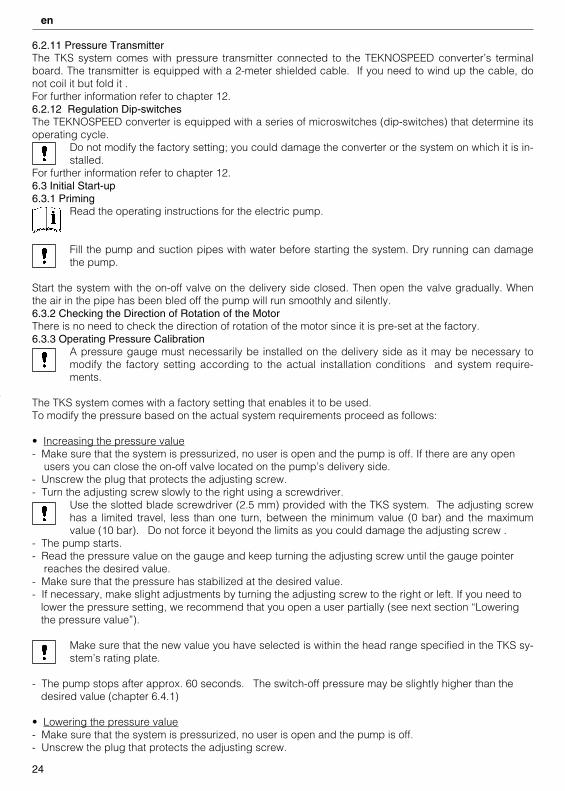
6.2.11 Pressure TransmitterThe TKS system comes with pressure transmitter connected to the TEKNOSPEED converter’s terminalboard. The transmitter is equipped with a 2-meter shielded cable. If you need to wind up the cable, donot coil it but fold it . For further information refer to chapter 12.6.2.12 Regulation Dip-switchesThe TEKNOSPEED converter is equipped with a series of microswitches (dip-switches) that determine itsoperating cycle.
Do not modify the factory setting; you could damage the converter or the system on which it is in-stalled.
For further information refer to chapter 12.6.3 Initial Start-up6.3.1 Priming
Read the operating instructions for the electric pump.
Fill the pump and suction pipes with water before starting the system. Dry running can damagethe pump.
Start the system with the on-off valve on the delivery side closed. Then open the valve gradually. Whenthe air in the pipe has been bled off the pump will run smoothly and silently.6.3.2 Checking the Direction of Rotation of the MotorThere is no need to check the direction of rotation of the motor since it is pre-set at the factory.6.3.3 Operating Pressure Calibration
A pressure gauge must necessarily be installed on the delivery side as it may be necessary tomodify the factory setting according to the actual installation conditions and system require-ments.
The TKS system comes with a factory setting that enables it to be used. To modify the pressure based on the actual system requirements proceed as follows:
• Increasing the pressure value- Make sure that the system is pressurized, no user is open and the pump is off. If there are any open
users you can close the on-off valve located on the pump’s delivery side.- Unscrew the plug that protects the adjusting screw.- Turn the adjusting screw slowly to the right using a screwdriver.
Use the slotted blade screwdriver (2.5 mm) provided with the TKS system. The adjusting screwhas a limited travel, less than one turn, between the minimum value (0 bar) and the maximumvalue (10 bar). Do not force it beyond the limits as you could damage the adjusting screw .
- The pump starts.- Read the pressure value on the gauge and keep turning the adjusting screw until the gauge pointer
reaches the desired value.- Make sure that the pressure has stabilized at the desired value.- If necessary, make slight adjustments by turning the adjusting screw to the right or left. If you need to
lower the pressure setting, we recommend that you open a user partially (see next section “Lowering the pressure value”).
Make sure that the new value you have selected is within the head range specified in the TKS sy-stem’s rating plate.
- The pump stops after approx. 60 seconds. The switch-off pressure may be slightly higher than thedesired value (chapter 6.4.1)
• Lowering the pressure value- Make sure that the system is pressurized, no user is open and the pump is off. - Unscrew the plug that protects the adjusting screw.
24
en
- Open the on-off valve located on the pump’s delivery side.- Open a user or the test tap (chapter 6.1) partially, allowing the pressure to drop slowly.- The pump starts.- Turn the adjusting screw slowly to the left using a screwdriver.
Use the slotted blade screwdriver (2.5 mm) provided with the TKS system. The adjusting screwhas a limited travel, less than one turn, between the minimum value (0 bar) and the maximumvalue (10 bar). Do not force it beyond the limits as you could damage the adjusting screw.
- Read the pressure value on the gauge and keep turning the adjusting screw until the gauge pointer reaches the desired value.
- Make sure that the pressure has stabilized at the desired value.- If necessary, make small adjustments by turning the adjusting screw to the right or left.
Make sure that the new value you have selected is within the head range specified in the TKS sy-stem’s rating plate.
- The pump stops after approx. 60 seconds. The switch-off pressure may be slightly higher than thedesired value (chapter 6.4.1).
For further information refer to chapter 12.
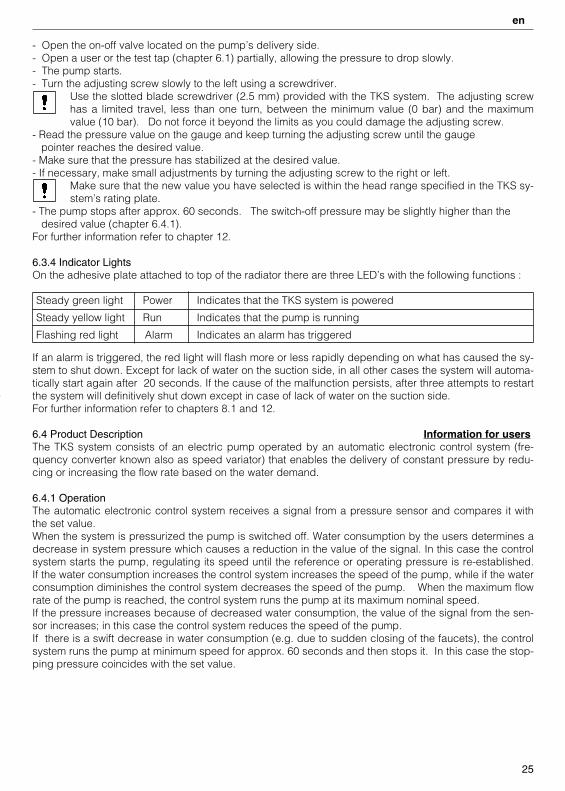
6.3.4 Indicator LightsOn the adhesive plate attached to top of the radiator there are three LED’s with the following functions :
Steady green light Power Indicates that the TKS system is powered
Steady yellow light Run Indicates that the pump is running
Flashing red light Alarm Indicates an alarm has triggered
If an alarm is triggered, the red light will flash more or less rapidly depending on what has caused the sy-stem to shut down. Except for lack of water on the suction side, in all other cases the system will automa-tically start again after 20 seconds. If the cause of the malfunction persists, after three attempts to restartthe system will definitively shut down except in case of lack of water on the suction side. For further information refer to chapters 8.1 and 12.
6.4 Product Description Information for usersThe TKS system consists of an electric pump operated by an automatic electronic control system (fre-quency converter known also as speed variator) that enables the delivery of constant pressure by redu-cing or increasing the flow rate based on the water demand.
6.4.1 Operation The automatic electronic control system receives a signal from a pressure sensor and compares it withthe set value. When the system is pressurized the pump is switched off. Water consumption by the users determines adecrease in system pressure which causes a reduction in the value of the signal. In this case the controlsystem starts the pump, regulating its speed until the reference or operating pressure is re-established.If the water consumption increases the control system increases the speed of the pump, while if the waterconsumption diminishes the control system decreases the speed of the pump. When the maximum flowrate of the pump is reached, the control system runs the pump at its maximum nominal speed.If the pressure increases because of decreased water consumption, the value of the signal from the sen-sor increases; in this case the control system reduces the speed of the pump.If there is a swift decrease in water consumption (e.g. due to sudden closing of the faucets), the controlsystem runs the pump at minimum speed for approx. 60 seconds and then stops it. In this case the stop-ping pressure coincides with the set value.
25
en

If the water consumption decreases gradually, the system runs the pump at a slightly higher pressure forapprox. 60 seconds (with transmitter full scale equal to 10 bar ➞ + 0.2 bar), and then stops it if there isno further water consumption.
If the system is powered the green (Power) light is on. When the pump is running the yellow (Run) light is on.If there is a shutdown or malfunction the red (Alarm) light comes on.If an alarm is triggered, the red light will blink more or less rapidly depending on the cause of the shut-down. Except for lack of water on the suction side, in all other cases the system will automatically startagain after 20 seconds. If the cause of the malfunction persists, after three attempts to restart the systemwill definitively shut down.
Refer to experienced and qualified personnel for any adjustments and/or maintenance opera-tions. Do not attempt to change the settings or open the control system.
Before using the equipment, read the manuals and store them safely.Store the screwdriver supplied with the TKS system in a safe place.
7. Maintenance Information for maintenance personnelObserve the following directions if you need to carry out any service operations on the product .
Maintenance operations must be performed by qualified personnel only.
Before carrying out any maintenance operations, make sure that all the connections (even thosethat are potential-free) are voltage-free.
Always disconnect the TEKNOSPEED converter from the power supply before carrying out anyoperations on the system’s mechanical or electrical components.After disconnection from the power source, wait at least 1 minute before carrying out any work onTEKNOSPEED to allow the condensers in the internal circuit to discharge.
Read this user’s manual and the operating instructions for the electric pump and diaphragm tank(if installed).
7.1 Routine MaintenanceThe TKS system does not require any routine maintenance provided that the working limits described inchapter 4 are observed.The pumps do not require any routine maintenance (read the pump’s manual). Check the air pre-charge in the surge tank, if installed, at least once a year (chapter 6.1.1).
7.2 Extraordinary Maintenance
Use adequate equipment and protections. Observe the accident prevention regulations in force.Lift and handle the pumps carefully, using suitable hoisting equipment.
Use only original spare parts to replace any worn or faulty components.
WARNING !Although the TKS system has a single-phase power supply, the pump’s motor is always a three-phasemotor connected to 230 V. The missing phases are created by the converter. For further information referto chapter 12.
26
en

8. Troubleshooting Information for users and maintenance personnel
Read this user’s manual and the operating instructions for the electric pump and diaphragm tank(if installed).
Maintenance operations must be performed by qualified personnel only.
For further information refer to chapters 7 and 12.
8.1 Visual Signaling Devices
8.1.1 Operation Signals
These basic signals are integrated by the alarm signals. Therefore there could be combinations of si-gnals such as green light on (power), yellow light off (pump off) and flashing red light (alarm).8.1.2 Alarm signalsIf an alarm is triggered the red light flashes more or less rapidly (flashing – pause – flashing) dependingon the cause of the system shutdown.
Be careful when servicing the system as it could restart automatically.
Shutdown caused by lack of water on suction sideIf the system shuts down because there is not enough water on the suction side, it will restart automati-cally only if the external device re-enables its operation (float switch or pressure switch or switch ➞ chap-ters 6.2.7 and 6.2.8).
Shutdown caused by other problems except for lack of water on suction sideIn all these cases the system restarts automatically after 20 seconds. If the cause of the malfunction per-sists, the system will shut down definitively after three attempts to start.
27
en
Red light (alarm) Flashing No signal from transmitter shutdown
Or shutdown caused by open external switch contact
Red light (alarm) Off No malfunction
Red light (alarm) Flashing Overcurrent shutdown
FlashingRed light (alarm) Converter overtemperature shutdown
Red light (alarm) Flashing Motor overtemperature shutdown
Red light (alarm) Flashing Shutdown caused by lack of water on suction side
Red light (alarm) Flashing
Red light (alarm) Flashing
Low voltage (undervoltage) shutdownProblems at serial output (for 2-pump units)
x 2 x 2
x 3 x 3
x 4 x 4
x 5 x 5
x 6 x 6
x 7 x 7
x 8 x 8
TKS_M0025_A_OT.XLS
TKS_M0026_A_OT.XLS

To reset the system, disconnect the power supply for at least one minute. If 10 minutes elapse after an alarm without any other malfunctions occurring, the alarm counter is resetand three new attempts are possible.
If two or more alarms are triggered simultaneously (e.g. due to motor overtemperature and lack of water),only the first malfunction signal received by the control board is signaled.
WARNING ! The converter does not have a non-erasable alarm log, we therefore recommend that youobserve the flashing frequency carefully before disconnecting the power supply to the TKSsystem.
For further information refer to chapters 8.1 and 12.
28
en
29
en
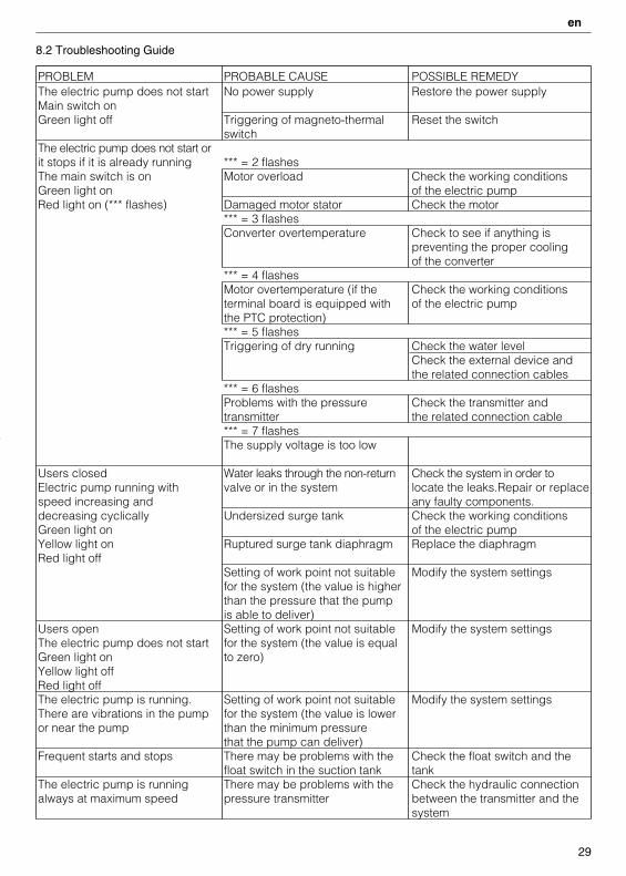
8.2 Troubleshooting Guide
PROBLEM PROBABLE CAUSE POSSIBLE REMEDYThe electric pump does not start No power supply Restore the power supplyMain switch onGreen light off Triggering of magneto-thermal Reset the switch
switchThe electric pump does not start orit stops if it is already running *** = 2 flashesThe main switch is on Motor overload Check the working conditionsGreen light on of the electric pumpRed light on (*** flashes) Damaged motor stator Check the motor
*** = 3 flashesConverter overtemperature Check to see if anything is
preventing the proper coolingof the converter
*** = 4 flashesMotor overtemperature (if the Check the working conditionsterminal board is equipped with of the electric pumpthe PTC protection)*** = 5 flashesTriggering of dry running Check the water level
Check the external device andthe related connection cables
*** = 6 flashesProblems with the pressure Check the transmitter andtransmitter the related connection cable*** = 7 flashesThe supply voltage is too low
Users closed Water leaks through the non-return Check the system in order toElectric pump running with valve or in the system locate the leaks.Repair or replacespeed increasing and any faulty components.decreasing cyclically Undersized surge tank Check the working conditionsGreen light on of the electric pumpYellow light on Ruptured surge tank diaphragm Replace the diaphragmRed light off
Setting of work point not suitable Modify the system settingsfor the system (the value is higherthan the pressure that the pumpis able to deliver)
Users open Setting of work point not suitable Modify the system settingsThe electric pump does not start for the system (the value is equalGreen light on to zero)Yellow light offRed light offThe electric pump is running. Setting of work point not suitable Modify the system settingsThere are vibrations in the pump for the system (the value is loweror near the pump than the minimum pressure
that the pump can deliver)Frequent starts and stops There may be problems with the Check the float switch and the
float switch in the suction tank tankThe electric pump is running There may be problems with the Check the hydraulic connectionalways at maximum speed pressure transmitter between the transmitter and the
system
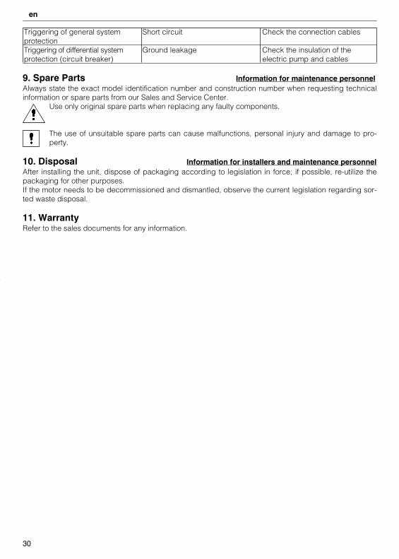
Triggering of general system Short circuit Check the connection cablesprotectionTriggering of differential system Ground leakage Check the insulation of theprotection (circuit breaker) electric pump and cables
9. Spare Parts Information for maintenance personnelAlways state the exact model identification number and construction number when requesting technicalinformation or spare parts from our Sales and Service Center.
Use only original spare parts when replacing any faulty components.
The use of unsuitable spare parts can cause malfunctions, personal injury and damage to pro-perty.
10. Disposal Information for installers and maintenance personnelAfter installing the unit, dispose of packaging according to legislation in force; if possible, re-utilize thepackaging for other purposes.If the motor needs to be decommissioned and dismantled, observe the current legislation regarding sor-ted waste disposal.
11. WarrantyRefer to the sales documents for any information.
30
en
it en fr de es pt nl
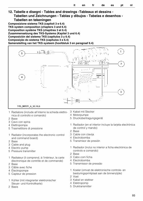
1 Radiatore (include all’interno la scheda elettro-nica di controllo e comando)
2 Base3 Cavo con spina4 Elettropompa5 Trasmettitore di pressione
1 Radiator (incorporates the electronic control and command board)
2 Base3 Cable and plug4 Electric pump5 Pressure transmitter
1 Radiateur (il comprend, à l’intérieur, la carteélectronique de contrôle et de commande)
2 Base3 Câble avec fiche4 Électropompe5 Capteur de pression
1 Kühler (mit integrierter elektronischerSteuer- und Kontrollkarte)
2 Basis
93
12. Tabelle e disegni - Tables and drawings -Tableaux et dessins - Tabellen und Zeichnungen - Tablas y dibujos - Tabelas e desenhos -Tabellen en tekeningen
Composizione sistema TKS (capitoli 3 e 6.4)TKS system composition (chapters 3 and 6.4)Composition système TKS (chapitres 3 et 6.4)Zusammensetzung des TKS-Systems (Kapitel 3 und 6.4)Composición del sistema TKS (capítulos 3 y 6.4)Composição do sistema TKS (capítulos 3 e 6.4)Samenstelling van het TKS systeem (hoofdstuk 3 en paragraaf 6.4)
3 Kabel mit Stecker4 Motorpumpe 5 Druckübertragungsgerät
1 Radiador (en el interior incluye la tarjeta electrónicade control y mando)
2 Base 3 Cable con clavija4 Electrobomba 5 Transmisor de presión
1 Radiador (inclui no interior a ficha electrónica de controlo e comando)
2 Base3 Cabo com ficha4 Electrobomba5 Transmissor de pressão
1 Koeler (omvat de elektronische controle- enbesturingsprintplaat aan de binnenzijde)
2 Voet3 Kabel en stekker4 Elektropomp5 Druktransmitter
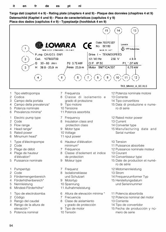
Targa dati (capitoli 4 e 9) - Rating plate (chapters 4 and 9) - Plaque des données (chapitres 4 et 9)Datenschild (Kapitel 4 und 9) - Placa de características (capítulos 4 y 9)Placa dos dados (capítulos 4 e 9) - Typeplaatje (hoofdstuk 4 en 9)
94
1 Tipo elettropompa2 Codice3 Campo della portata4 Campo della prevalenza*5 Potenza nominale6 Prevalenza minima*
7 Frequenza8 Classe di isolamento e
grado di protezione9 Tipo motore10 Tensione11 Potenza assorbita
12 Potenza nominale motore13 Corrente14 Tipo convertitore15 Data di produzione e nume-
ro di serie
1 Tipo de electrobomba2 Código3 Rango del caudal4 Rango de la altura de
elevación *5 Potencia nominal
6 Altura de elevación mínima *7 Frecuencia8 Clase de aislamiento
y grado de protección9 Tipo de motor10 Tensión
11 Potencia absorbida12 Potencia nominal del motor13 Corriente14 Tipo de convertidor15 Fecha de producción y nú-
mero de serie
1 Electric pump type2 Code3 Flow range 4 Head range*5 Rated power6 Minumum head*
7 Frequency8 Insulation class and
protection class9 Motor type10 Voltage11 nput power
12 Rated motor power13 Current14 Converter type15 Manufacturing date and
Serial number
1 Type d’électropompe2 Code3 Plage de débit 4 Plage de hauteur
d’élévation*5 Puissance nominale
6 Hauteur d’élévationminimum*
7 Fréquence8 Classe d’isolement et indice
de protection9 Moteur type
10 Tension11 Puissance absorbée12 Puissance nominale moteur13 Courant14 Convertisseur type 15 Date de production et numé-
ro de série
1 Pumpentyp2 Code3 Fördermengenbereich4 Förderhöhenbereich*5 Nennleistung 6 Mindest-Förderhöhe*
7 Frequenz 8 Isolationsklasse
und Schutzart 9 Motortyp 10 Spannung 11 Aufnahmeleistung
12 Motornennleistung 13 Strom14 Frequenzumformer Typ15 Herstellungsdatum
und Seriennummer
it en fr de es pt nl
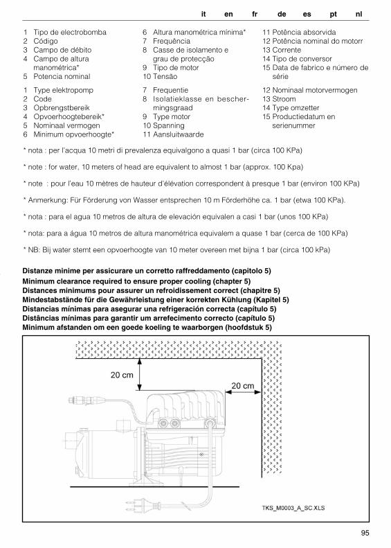
Distanze minime per assicurare un corretto raffreddamento (capitolo 5) Minimum clearance required to ensure proper cooling (chapter 5)Distances minimums pour assurer un refroidissement correct (chapitre 5)Mindestabstände für die Gewährleistung einer korrekten Kühlung (Kapitel 5)Distancias mínimas para asegurar una refrigeración correcta (capítulo 5)Distâncias mínimas para garantir um arrefecimento correcto (capítulo 5)Minimum afstanden om een goede koeling te waarborgen (hoofdstuk 5)
95
1 Tipo de electrobomba2 Código3 Campo de débito4 Campo de altura
manométrica*5 Potencia nominal
6 Altura manométrica mínima*7 Frequência8 Casse de isolamento e
grau de protecção9 Tipo de motor10 Tensão
11 Potência absorvida12 Potência nominal do motorr13 Corrente14 Tipo de conversor15 Data de fabrico e número de
série
* nota : per l’acqua 10 metri di prevalenza equivalgono a quasi 1 bar (circa 100 KPa)
* note : for water, 10 meters of head are equivalent to almost 1 bar (approx. 100 Kpa)
* note : pour l’eau 10 mètres de hauteur d’élévation correspondent à presque 1 bar (environ 100 KPa)
* Anmerkung: Für Förderung von Wasser entsprechen 10 m Förderhöhe ca. 1 bar (etwa 100 KPa).
* nota : para el agua 10 metros de altura de elevación equivalen a casi 1 bar (unos 100 KPa)
* nota: para a água 10 metros de altura manométrica equivalem a quase 1 bar (cerca de 100 KPa)
* NB: Bij water stemt een opvoerhoogte van 10 meter overeen met bijna 1 bar (circa 100 kPa)
1 Type elektropomp2 Code3 Opbrengstbereik4 Opvoerhoogtebereik*5 Nominaal vermogen6 Minimum opvoerhoogte*
7 Frequentie8 Isolatieklasse en bescher-
mingsgraad9 Type motor10 Spanning11 Aansluitwaarde
12 Nominaal motorvermogen13 Stroom14 Type omzetter15 Productiedatum en
serienummer
it en fr de es pt nl
96
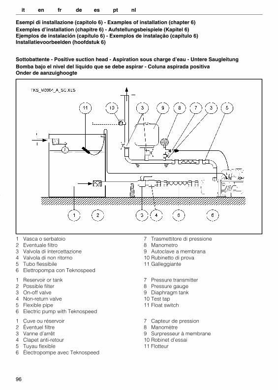
Esempi di installazione (capitolo 6) - Examples of installation (chapter 6)Exemples d’installation (chapitre 6) - Aufstellungsbeispiele (Kapitel 6)Ejemplos de instalación (capítulo 6) - Exemplos de instalação (capítulo 6)Installatievoorbeelden (hoofdstuk 6)
Sottobattente - Positive suction head - Aspiration sous charge d’eau - Untere SaugleitungBomba bajo el nivel del líquido que se debe aspirar - Coluna aspirada positivaOnder de aanzuighoogte
1 Vasca o serbatoio2 Eventuale filtro3 Valvola di intercettazione4 Valvola di non ritorno5 Tubo flessibile6 Elettropompa con Teknospeed
7 Trasmettitore di pressione8 Manometro9 Autoclave a membrana10 Rubinetto di prova11 Galleggiante
1 Reservoir or tank2 Possible filter3 On-off valve4 Non-return valve5 Flexible pipe6 Electric pump with Teknospeed
7 Pressure transmitter8 Pressure gauge9 Diaphragm tank10 Test tap11 Float switch
1 Cuve ou réservoir2 Éventuel filtre3 Vanne d’arrêt4 Clapet anti-retour5 Tuyau flexible6 Électropompe avec Teknospeed
7 Capteur de pression8 Manomètre9 Surpresseur à membrane10 Robinet d’essai11 Flotteur
it en fr de es pt nl
97
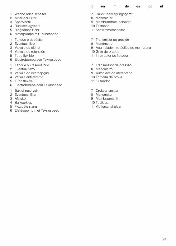
1 Wanne oder Behälter2 Allfälliger Filter 3 Sperrventil4 Rückschlagventil5 Biegsames Rohr 6 Motorpumpe mit Teknospeed
7 Druckübertragungsgerät8 Manometer 9 Membrandruckbehälter10 Testhahn 11 Schwimmerschalter
1 Tanque o depósito2 Eventual filtro3 Válvula de cierre4 Válvula de retención5 Tubo flexible6 Electrobomba con Teknospeed
7 Transmisor de presión8 Manómetro9 Acumulador hidráulico de membrana10 Grifo de prueba11 Interruptor de flotador
1 Tanque ou reservatório2 Eventual filtro3 Válvula de intercepção4 Válvula anti-retorno5 Tubo flexível6 Electrobomba com Teknospeed
7 Transmissor de pressão8 Manómetro9 Autoclave de membrana10 Torneira de prova11 Flutuador
1 Bak of reservoir2 Eventueel filter3 Afsluiter4 Balkeerklep5 Flexibele slang6 Elektropomp met Teknospeed
7 Druktransmitter8 Manometer9 Membraantank10 Testkraan11 Vlotterschakelaar
it en fr de es pt nl
98
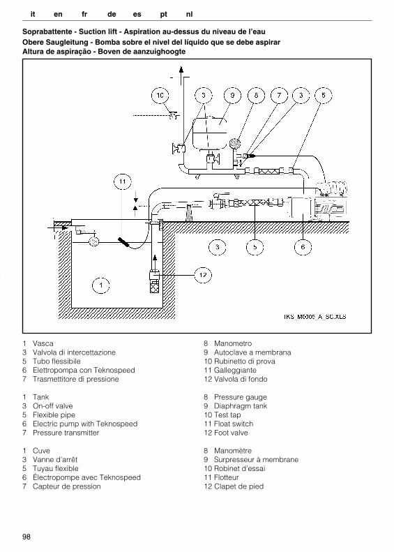
1 Vasca3 Valvola di intercettazione5 Tubo flessibile6 Elettropompa con Teknospeed7 Trasmettitore di pressione
8 Manometro9 Autoclave a membrana10 Rubinetto di prova11 Galleggiante12 Valvola di fondo
1 Tank3 On-off valve5 Flexible pipe6 Electric pump with Teknospeed7 Pressure transmitter
8 Pressure gauge 9 Diaphragm tank10 Test tap11 Float switch 12 Foot valve
1 Cuve3 Vanne d’arrêt5 Tuyau flexible6 Électropompe avec Teknospeed7 Capteur de pression
8 Manomètre9 Surpresseur à membrane10 Robinet d’essai 11 Flotteur12 Clapet de pied
Soprabattente - Suction lift - Aspiration au-dessus du niveau de l’eauObere Saugleitung - Bomba sobre el nivel del líquido que se debe aspirarAltura de aspiração - Boven de aanzuighoogte
it en fr de es pt nl
99
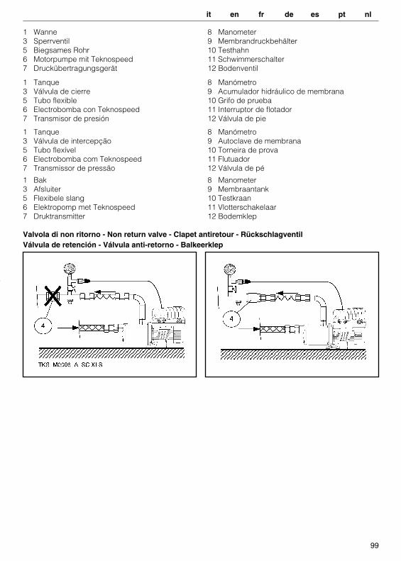
1 Wanne3 Sperrventil5 Biegsames Rohr6 Motorpumpe mit Teknospeed7 Druckübertragungsgerät
8 Manometer9 Membrandruckbehälter10 Testhahn11 Schwimmerschalter12 Bodenventil
1 Tanque 3 Válvula de intercepção5 Tubo flexível6 Electrobomba com Teknospeed7 Transmissor de pressão
8 Manómetro9 Autoclave de membrana10 Torneira de prova11 Flutuador12 Válvula de pé
1 Tanque3 Válvula de cierre5 Tubo flexible 6 Electrobomba con Teknospeed 7 Transmisor de presión
8 Manómetro9 Acumulador hidráulico de membrana10 Grifo de prueba11 Interruptor de flotador12 Válvula de pie
1 Bak3 Afsluiter5 Flexibele slang6 Elektropomp met Teknospeed7 Druktransmitter
8 Manometer9 Membraantank10 Testkraan11 Vlotterschakelaar12 Bodemklep
Valvola di non ritorno - Non return valve - Clapet antiretour - RückschlagventilVálvula de retención - Válvula anti-retorno - Balkeerklep
it en fr de es pt nl
100
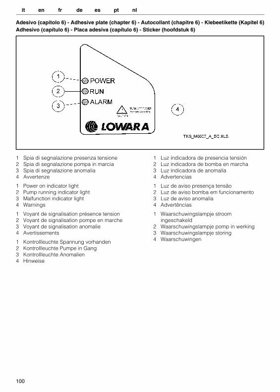
Adesivo (capitolo 6) - Adhesive plate (chapter 6) - Autocollant (chapitre 6) - Klebeetikette (Kapitel 6)Adhesivo (capítulo 6) - Placa adesiva (capítulo 6) - Sticker (hoofdstuk 6)
1 Spia di segnalazione presenza tensione2 Spia di segnalazione pompa in marcia3 Spia di segnalazione anomalia4 Avvertenze
1 Luz indicadora de presencia tensión2 Luz indicadora de bomba en marcha3 Luz indicadora de anomalía4 Advertencias
1 Power on indicator light2 Pump running indicator light3 Malfunction indicator light4 Warnings
1 Luz de aviso presença tensão2 Luz de aviso bomba em funcionamento3 Luz de aviso anomalia4 Advertências
1 Voyant de signalisation présence tension2 Voyant de signalisation pompe en marche3 Voyant de signalisation anomalie4 Avertissements
1 Waarschuwingslampje stroomingeschakeld
2 Waarschuwingslampje pomp in werking3 Waarschuwingslampje storing4 Waarschuwingen1 Kontrollleuchte Spannung vorhanden
2 Kontrollleuchte Pumpe in Gang3 Kontrollleuchte Anomalien4 Hinweise
it en fr de es pt nl
101
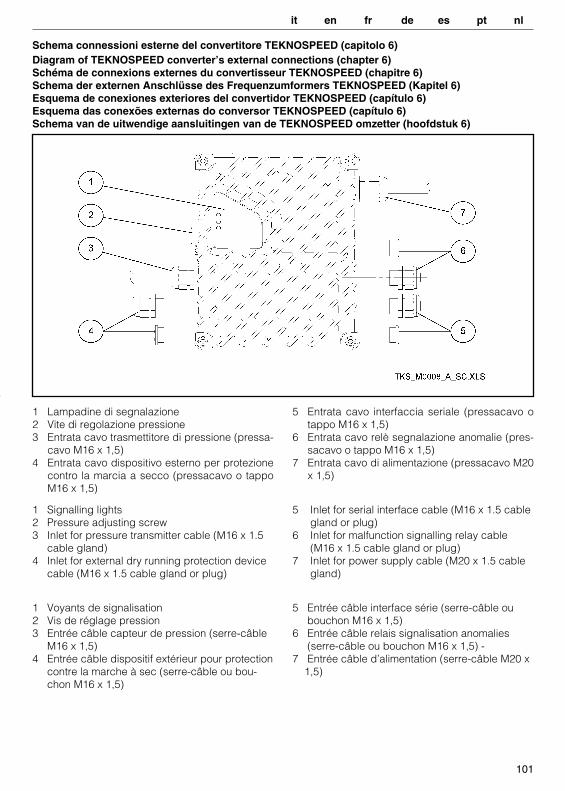
Schema connessioni esterne del convertitore TEKNOSPEED (capitolo 6) Diagram of TEKNOSPEED converter’s external connections (chapter 6) Schéma de connexions externes du convertisseur TEKNOSPEED (chapitre 6) Schema der externen Anschlüsse des Frequenzumformers TEKNOSPEED (Kapitel 6)Esquema de conexiones exteriores del convertidor TEKNOSPEED (capítulo 6)Esquema das conexões externas do conversor TEKNOSPEED (capítulo 6)Schema van de uitwendige aansluitingen van de TEKNOSPEED omzetter (hoofdstuk 6)
1 Lampadine di segnalazione2 Vite di regolazione pressione3 Entrata cavo trasmettitore di pressione (pressa-
cavo M16 x 1,5)4 Entrata cavo dispositivo esterno per protezione
contro la marcia a secco (pressacavo o tappoM16 x 1,5)
5 Entrata cavo interfaccia seriale (pressacavo otappo M16 x 1,5)
6 Entrata cavo relè segnalazione anomalie (pres-sacavo o tappo M16 x 1,5)
7 Entrata cavo di alimentazione (pressacavo M20x 1,5)
1 Signalling lights2 Pressure adjusting screw3 Inlet for pressure transmitter cable (M16 x 1.5
cable gland)4 Inlet for external dry running protection device
cable (M16 x 1.5 cable gland or plug)
5 Inlet for serial interface cable (M16 x 1.5 cablegland or plug)
6 Inlet for malfunction signalling relay cable (M16 x 1.5 cable gland or plug)
7 Inlet for power supply cable (M20 x 1.5 cable gland)
1 Voyants de signalisation2 Vis de réglage pression3 Entrée câble capteur de pression (serre-câble
M16 x 1,5)4 Entrée câble dispositif extérieur pour protection
contre la marche à sec (serre-câble ou bou-chon M16 x 1,5)
5 Entrée câble interface série (serre-câble ou bouchon M16 x 1,5)
6 Entrée câble relais signalisation anomalies (serre-câble ou bouchon M16 x 1,5) -
7 Entrée câble d’alimentation (serre-câble M20 x1,5)
it en fr de es pt nl

102
1 Signallampen2 Druckregulierungschraube 3 Kabeleingang des Druckübertragungsgerät
(Kabelniederhalter M16 x 1,5)4 Kabeleingang der externen
Trockenlaufvorrichtung (Kabelniederhalter oder Stopfen M16 x 1,5)
5 Kabeleingang der Serienschnittstelle (Kabelniederhalter oder Stopfen M16 x 1,5)
6 Kabeleingang des Anzeigerelais der Anomalien (Kabelniederhalter oder Stopfen M16 x 1,5)
7 Speisekabeleingang (Kabelniederhalter M20 x 1,5)
1 Bombillas de indicación2 Tornillo de regulación presión3 Entrada cable transmisor de presión (sujetaca-
ble M16 x 1,5)4 Entrada cable dispositivo exterior de protec-
ción contra la marcha en seco (sujetacable o tapón M16 x 1,5)
5 Entrada cable interfaz serial (sujetacable o tapón M16 x 1,5)
6 Entrada cable relé de indicación anomalías (sujetacable o tapón M16 x 1,5)
7 Entrada cable de alimentación (sujetacable M20 x 1,5)
1 Lâmpadas de sinalização2 Parafuso de regulação da pressão 3 Entrada cabo transmissor de pressão
(prensa-cabo M16 x 1,5)4 Entrada cabo dispositivo externo para
protecção contra o funcionamento a seco (prensa-cabo ou tampão M16 x 1,5)
5 Entrada cabo interface série (prensa-cabo ou tampão M16 x 1,5)
6 Entrada cabo relé sinalização anomalias (pren-sa-cabo ou tampão M16 x 1,5)
7 Entrada cabo de alimentação (prensa-cabo M20 x 1,5)
1 Waarschuwingslampjes2 Drukregelschroef3 Ingang kabel druktransmitter (kabelklem M16 x
1,5)4 Ingang kabel uitwendig systeem voor
beveiliging tegen drooglopen (kabelklem of plug M16 x 1,5)
5 Ingang kabel seriële interface (kabelklem of plug M16 x 1,5)
6 Ingang kabel waarschuwingsrelais storingen (kabelklem of plug M16 x 1,5)
7 Ingang voedingskabel (kabelklem of plug M20 x 1,5)
it en fr de es pt nl
103
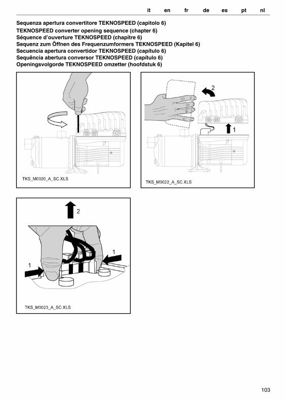
Sequenza apertura convertitore TEKNOSPEED (capitolo 6)TEKNOSPEED converter opening sequence (chapter 6)Séquence d’ouverture TEKNOSPEED (chapitre 6) Sequenz zum Öffnen des Frequenzumformers TEKNOSPEED (Kapitel 6)Secuencia apertura convertidor TEKNOSPEED (capítulo 6)Sequência abertura conversor TEKNOSPEED (capítulo 6)Openingsvolgorde TEKNOSPEED omzetter (hoofdstuk 6)
it en fr de es pt nl
104
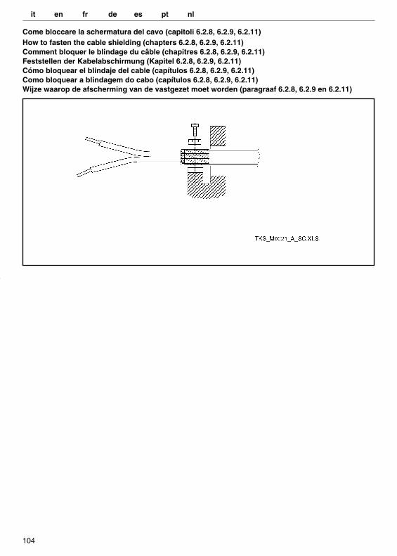
Come bloccare la schermatura del cavo (capitoli 6.2.8, 6.2.9, 6.2.11)How to fasten the cable shielding (chapters 6.2.8, 6.2.9, 6.2.11)Comment bloquer le blindage du câble (chapitres 6.2.8, 6.2.9, 6.2.11)Feststellen der Kabelabschirmung (Kapitel 6.2.8, 6.2.9, 6.2.11)Cómo bloquear el blindaje del cable (capítulos 6.2.8, 6.2.9, 6.2.11)Como bloquear a blindagem do cabo (capítulos 6.2.8, 6.2.9, 6.2.11)Wijze waarop de afscherming van de vastgezet moet worden (paragraaf 6.2.8, 6.2.9 en 6.2.11)
it en fr de es pt nl
105
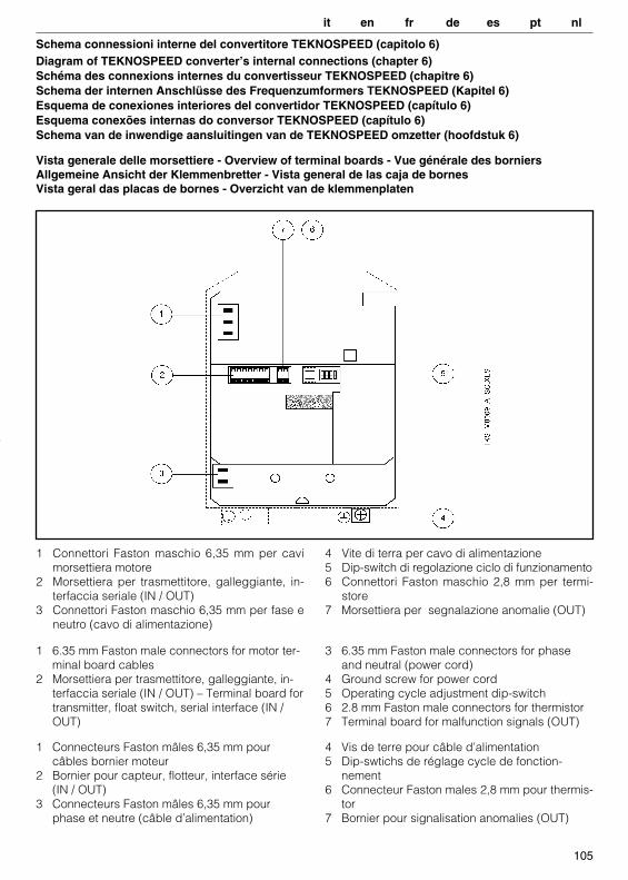
Schema connessioni interne del convertitore TEKNOSPEED (capitolo 6)Diagram of TEKNOSPEED converter’s internal connections (chapter 6)Schéma des connexions internes du convertisseur TEKNOSPEED (chapitre 6)Schema der internen Anschlüsse des Frequenzumformers TEKNOSPEED (Kapitel 6)Esquema de conexiones interiores del convertidor TEKNOSPEED (capítulo 6)Esquema conexões internas do conversor TEKNOSPEED (capítulo 6) Schema van de inwendige aansluitingen van de TEKNOSPEED omzetter (hoofdstuk 6)
1 Connettori Faston maschio 6,35 mm per cavimorsettiera motore
2 Morsettiera per trasmettitore, galleggiante, in-terfaccia seriale (IN / OUT)
3 Connettori Faston maschio 6,35 mm per fase eneutro (cavo di alimentazione)
4 Vite di terra per cavo di alimentazione5 Dip-switch di regolazione ciclo di funzionamento6 Connettori Faston maschio 2,8 mm per termi-
store7 Morsettiera per segnalazione anomalie (OUT)
1 6.35 mm Faston male connectors for motor ter-minal board cables
2 Morsettiera per trasmettitore, galleggiante, in-terfaccia seriale (IN / OUT) – Terminal board for transmitter, float switch, serial interface (IN / OUT)
3 6.35 mm Faston male connectors for phase and neutral (power cord)
4 Ground screw for power cord5 Operating cycle adjustment dip-switch6 2.8 mm Faston male connectors for thermistor7 Terminal board for malfunction signals (OUT)
1 Connecteurs Faston mâles 6,35 mm pour câbles bornier moteur
2 Bornier pour capteur, flotteur, interface série (IN / OUT)
3 Connecteurs Faston mâles 6,35 mm pour phase et neutre (câble d’alimentation)
4 Vis de terre pour câble d’alimentation5 Dip-swtichs de réglage cycle de fonction-
nement6 Connecteur Faston males 2,8 mm pour thermis-
tor7 Bornier pour signalisation anomalies (OUT)
Vista generale delle morsettiere - Overview of terminal boards - Vue générale des borniersAllgemeine Ansicht der Klemmenbretter - Vista general de las caja de bornesVista geral das placas de bornes - Overzicht van de klemmenplaten
it en fr de es pt nl
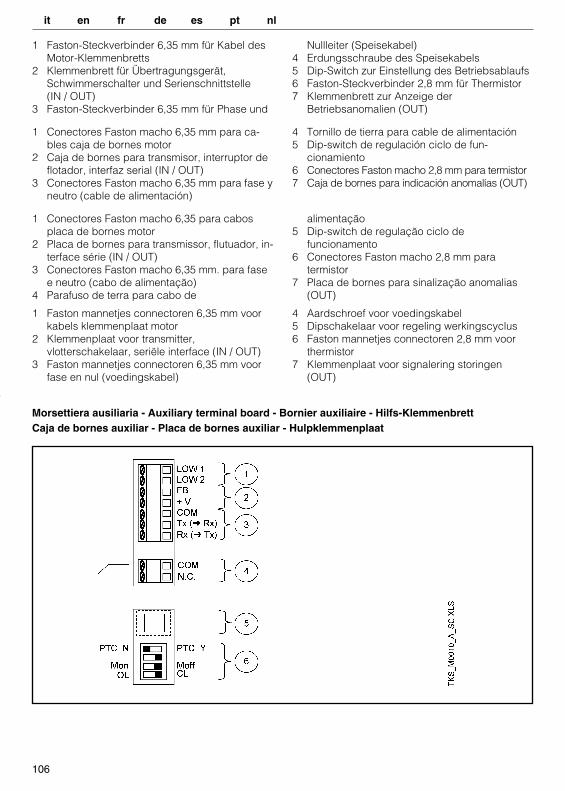
Morsettiera ausiliaria - Auxiliary terminal board - Bornier auxiliaire - Hilfs-KlemmenbrettCaja de bornes auxiliar - Placa de bornes auxiliar - Hulpklemmenplaat
106
1 Faston-Steckverbinder 6,35 mm für Kabel des Motor-Klemmenbretts
2 Klemmenbrett für Übertragungsgerät, Schwimmerschalter und Serienschnittstelle(IN / OUT)
3 Faston-Steckverbinder 6,35 mm für Phase und
Nullleiter (Speisekabel)4 Erdungsschraube des Speisekabels5 Dip-Switch zur Einstellung des Betriebsablaufs6 Faston-Steckverbinder 2,8 mm für Thermistor7 Klemmenbrett zur Anzeige der
Betriebsanomalien (OUT)
1 Conectores Faston macho 6,35 mm para ca-bles caja de bornes motor
2 Caja de bornes para transmisor, interruptor de flotador, interfaz serial (IN / OUT)
3 Conectores Faston macho 6,35 mm para fase y neutro (cable de alimentación)
4 Tornillo de tierra para cable de alimentación5 Dip-switch de regulación ciclo de fun-
cionamiento6 Conectores Faston macho 2,8 mm para termistor7 Caja de bornes para indicación anomalías (OUT)
1 Conectores Faston macho 6,35 para cabos placa de bornes motor
2 Placa de bornes para transmissor, flutuador, in-terface série (IN / OUT)
3 Conectores Faston macho 6,35 mm. para fase e neutro (cabo de alimentação)
4 Parafuso de terra para cabo de
alimentação5 Dip-switch de regulação ciclo de
funcionamento6 Conectores Faston macho 2,8 mm para
termistor7 Placa de bornes para sinalização anomalias
(OUT)
1 Faston mannetjes connectoren 6,35 mm voor kabels klemmenplaat motor
2 Klemmenplaat voor transmitter,vlotterschakelaar, seriële interface (IN / OUT)
3 Faston mannetjes connectoren 6,35 mm voor fase en nul (voedingskabel)
4 Aardschroef voor voedingskabel5 Dipschakelaar voor regeling werkingscyclus6 Faston mannetjes connectoren 2,8 mm voor
thermistor7 Klemmenplaat voor signalering storingen
(OUT)
it en fr de es pt nl
107
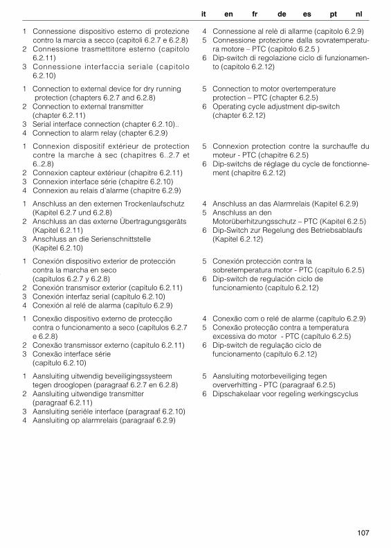
1 Connessione dispositivo esterno di protezionecontro la marcia a secco (capitoli 6.2.7 e 6.2.8)
2 Connessione trasmettitore esterno (capitolo6.2.11)
3 Connessione interfaccia seriale (capitolo6.2.10)
4 Connessione al relè di allarme (capitolo 6.2.9)5 Connessione protezione dalla sovratemperatu-
ra motore – PTC (capitolo 6.2.5 )6 Dip-switch di regolazione ciclo di funzionamen-
to (capitolo 6.2.12)
1 Connection to external device for dry running protection (chapters 6.2.7 and 6.2.8)
2 Connection to external transmitter(chapter 6.2.11)
3 Serial interface connection (chapter 6.2.10)..4 Connection to alarm relay (chapter 6.2.9)
5 Connection to motor overtemperatureprotection – PTC (chapter 6.2.5)
6 Operating cycle adjustment dip-switch(chapter 6.2.12)
1 Connexion dispositif extérieur de protectioncontre la marche à sec (chapitres 6..2.7 et6..2.8)
2 Connexion capteur extérieur (chapitre 6.2.11)3 Connexion interface série (chapitre 6.2.10) 4 Connexion au relais d’alarme (chapitre 6.2.9)
5 Connexion protection contre la surchauffe dumoteur - PTC (chapitre 6.2.5)
6 Dip-switchs de réglage du cycle de fonctionne-ment (chapitre 6.2.12)
1 Anschluss an den externen Trockenlaufschutz (Kapitel 6.2.7 und 6.2.8)
2 Anschluss an das externe Übertragungsgeräts (Kapitel 6.2.11)
3 Anschluss an die Serienschnittstelle(Kapitel 6.2.10)
4 Anschluss an das Alarmrelais (Kapitel 6.2.9)5 Anschluss an den
Motorüberhitzungsschutz – PTC (Kapitel 6.2.5) 6 Dip-Switch zur Regelung des Betriebsablaufs
(Kapitel 6.2.12)
1 Conexión dispositivo exterior de protección contra la marcha en seco(capítulos 6.2.7 y 6.2.8)
2 Conexión transmisor exterior (capítulo 6.2.11) 3 Conexión interfaz serial (capítulo 6.2.10)4 Conexión al relé de alarma (capítulo 6.2.9)
5 Conexión protección contra lasobretemperatura motor - PTC (capítulo 6.2.5)
6 Dip-switch de regulación ciclo defuncionamiento (capítulo 6.2.12)
1 Conexão dispositivo externo de protecçãocontra o funcionamento a seco (capítulos 6.2.7 e 6.2.8)
2 Conexão transmissor externo (capítulo 6.2.11)3 Conexão interface série
(capítulo 6.2.10)
4 Conexão com o relé de alarme (capítulo 6.2.9)5 Conexão protecção contra a temperatura
excessiva do motor - PTC (capítulo 6.2.5)6 Dip-switch de regulação ciclo de
funcionamento (capítulo 6.2.12)
1 Aansluiting uitwendig beveiligingssysteem tegen drooglopen (paragraaf 6.2.7 en 6.2.8)
2 Aansluiting uitwendige transmitter(paragraaf 6.2.11)
3 Aansluiting seriële interface (paragraaf 6.2.10)4 Aansluiting op alarmrelais (paragraaf 6.2.9)
5 Aansluiting motorbeveiliging tegenoververhitting - PTC (paragraaf 6.2.5)
6 Dipschakelaar voor regeling werkingscyclus
it en fr de es pt nl

108
Connessione alla protezione dalla sovratemperatura motore – PTC (capitolo 6.2.5)Connection to motor overtemperature protection – PTC (chapter 6.2.5)Connexion protection contre la surchauffe du moteur - PTC (chapitre 6.2.5)Anschluss an den Motorüberhitzungsschutz – PTC (Kapitel 6.2.5)Conexión a la protección contra la sobretemperatura motor - PTC (capítulo 6.2.5)Conexão com a protecção contra a temperatura excessiva do motor – PTC (capítulo 6.2.5)Aansluiting op motorbeveiliging tegen oververhitting - PTC (paragraaf 6.2.5)
it en fr de es pt nl

109
Connessione al dispositivo esterno di protezione contro la marcia a secco (capitoli 6.2.7 e 6.2.8)Connection to external device for dry running protection (chapters 6.2.7 and 6.2.8)Connexion au dispositif extérieur de protection contre la marche à sec (chapitres 6.2.7 et 6.2.8)Anschluss an den externen Trockenlaufschutz (Kapitel 6.2.7 und 6.2.8)Conexión al dispositivo exterior de protección contra la marcha en seco (capítulos 6.2.7 y 6.2.8)Conexão com o dispositivo externo de protecção contra o funcionamento a seco (capítulos 6.2.7 e 6.2.8)Aansluiting op uitwendig beveiligingssysteem tegen drooglopen (paragraaf 6.2.7 en 6.2.8)
1 Galleggiante o pressostato2 No external device
1 Float or pressure switch2 Nessun dispositivo esterno
1 Flotteur ou pressostat 2 Aucun dispositif extérieur
1 Schwimmerschalter oder Druckwächter2 Keine externe Vorrichtung
1 Interruptor de flotador o presóstato2 Ningún dispositivo exterior
1 Flutuador ou pressostato 2 Nenhum dispositivo externo
1 Vlotterschakelaar of drukregelaar2 Geen uitwendig systeem
it en fr de es pt nl

110
Connessione al relè di allarme (capitolo 6.2.9Connection to alarm relay (chapter 6.2.9)Connexion au relais d’alarme (chapitre 6.2.9)Anschluss an das Alarmrelais (Kapitel 6.2.9)Conexión al relé de alarma (capítulo 6.2.9)Conexão com o relé de alarme (capítulo 6.2.9)Aansluiting op het alarmrelais (paragraaf 6.2.9)
* massimo 230 Vca, massimo 1 A di solo carico resistivo* maximum 230 Vac, maximum 1 A of resistive load only* maximum 230 Vca, maximum 1 A de charge résistive uniquement* max. 230 Vca, max. 1 A reine Ohmlast* máximo 230 Vca, máximo 1 A de sólo carga resistiva* máximo 230 Vca, máximo 1 A só de carga resisitiva * maximum 230 Vac, maximum 1 A alleen weerstandsbelasting
it en fr de es pt nl

111
Connessione interfaccia seriale (capitolo 6.2.10)Serial interface connection (chapter 6.2.10)Connexion interface série (chapitre 6.2.10)Anschluss an die Serienschnittstelle (Kapitel 6.2.10)Conexión interfaz serial (capítulo 6.2.10) Conexão interface série (capítulo 6.2.10)Aansluiting seriële interface (paragraaf 6.2.10)
it en fr de es pt nl
112
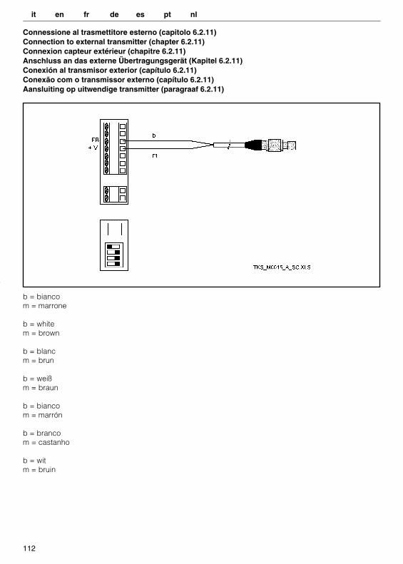
b = bianco m = marrone
b = white m = brown
b = blancm = brun
b = weißm = braun
b = bianco m = marrón
b = branco m = castanho
b = witm = bruin
Connessione al trasmettitore esterno (capitolo 6.2.11)Connection to external transmitter (chapter 6.2.11)Connexion capteur extérieur (chapitre 6.2.11)Anschluss an das externe Übertragungsgerät (Kapitel 6.2.11)Conexión al transmisor exterior (capítulo 6.2.11)Conexão com o transmissor externo (capítulo 6.2.11)Aansluiting op uitwendige transmitter (paragraaf 6.2.11)
it en fr de es pt nl
113
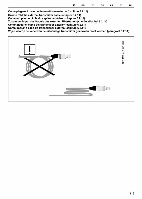
Come piegare il cavo del trasmettitore esterno (capitolo 6.2.11) How to fold the external transmitter cable (chapter 6.2.11)Comment plier le câble du capteur extérieur (chapitre 6.2.11)Zusammenlegen des Kabels des externen Übertragungsgeräts (Kapitel 6.2.11)Cómo plegar el cable del transmisor exterior (capítulo 6.2.11)Como dobrar o cabo do transmissor externo (capítulo 6.2.11)Wijze waarop de kabel van de uitwendige transmitter gevouwen moet worden (paragraaf 6.2.11)
it en fr de es pt nl
114
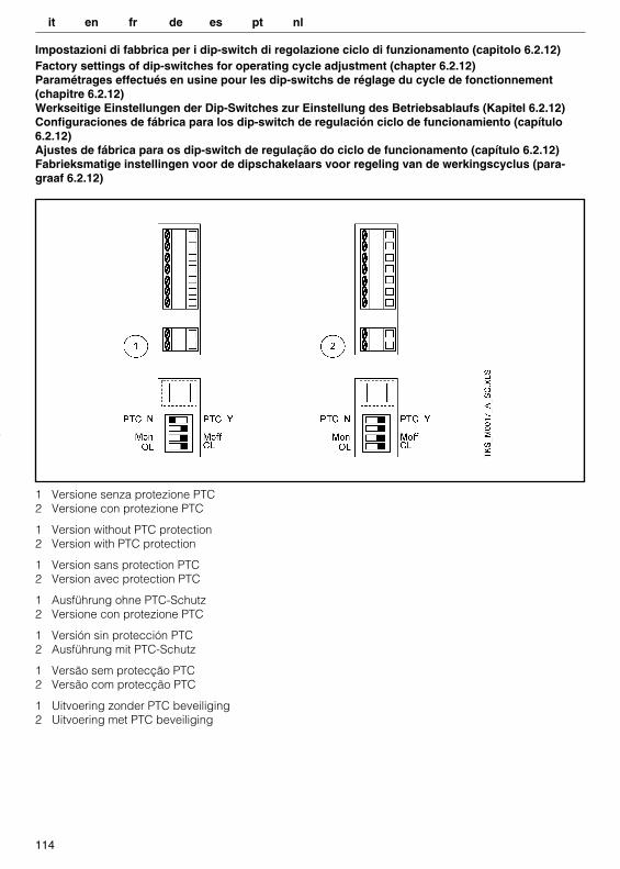
1 Versione senza protezione PTC2 Versione con protezione PTC
1 Version without PTC protection2 Version with PTC protection
1 Version sans protection PTC2 Version avec protection PTC
1 Ausführung ohne PTC-Schutz2 Versione con protezione PTC
1 Versión sin protección PTC2 Ausführung mit PTC-Schutz
1 Versão sem protecção PTC2 Versão com protecção PTC
1 Uitvoering zonder PTC beveiliging2 Uitvoering met PTC beveiliging
Impostazioni di fabbrica per i dip-switch di regolazione ciclo di funzionamento (capitolo 6.2.12)Factory settings of dip-switches for operating cycle adjustment (chapter 6.2.12)Paramétrages effectués en usine pour les dip-switchs de réglage du cycle de fonctionnement(chapitre 6.2.12)Werkseitige Einstellungen der Dip-Switches zur Einstellung des Betriebsablaufs (Kapitel 6.2.12)Configuraciones de fábrica para los dip-switch de regulación ciclo de funcionamiento (capítulo6.2.12) Ajustes de fábrica para os dip-switch de regulação do ciclo de funcionamento (capítulo 6.2.12)Fabrieksmatige instellingen voor de dipschakelaars voor regeling van de werkingscyclus (para-graaf 6.2.12)
it en fr de es pt nl

115
Procedure di modifica taratura di fabbrica (capitolo 6.3.3) Factory settings modification procedures (chapter 6.3.3)Procédures de modification des réglages effectués en usine (chapitre 6.3.3)Vorgehen zur Änderung der werkseitigen Einstellungen (Kapitel 6.3.3)Procedimientos de modificación calibrado de fábrica (capítulo 6.3.3)Procedimento de modificação do ajuste de fábrica (capítulo 6.3.3)Wijzigingsprocedure van de fabrieksmatige instellingen (paragraaf 6.3.3)
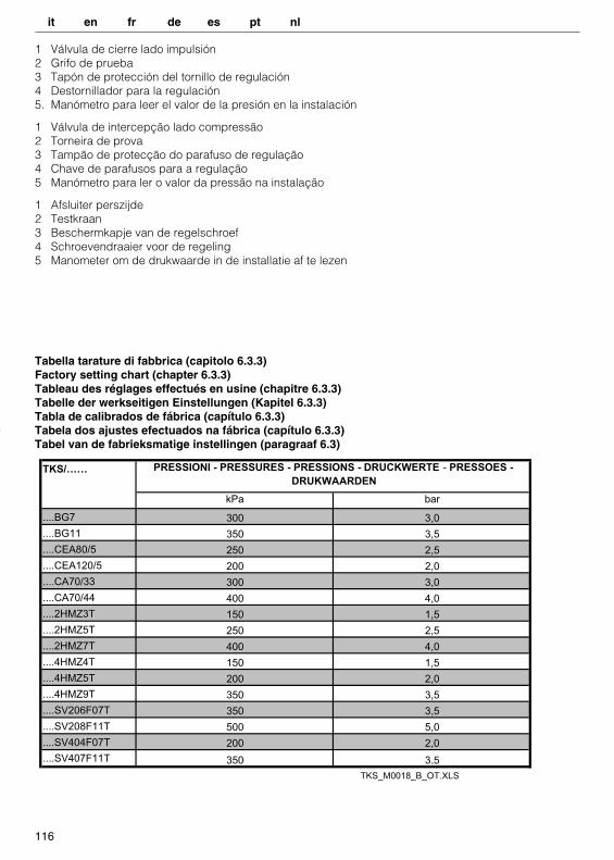
1 Valvola di intercettazione lato mandata2 Rubinetto di prova3 Tappo di protezione della vite di regolazione4 Cacciavite per la regolazione5 Manometro per leggere il valore della pressione nell’impianto
1 On-off valve on delivery side 2 Test tap 3 Adjusting screw protection plug 4 Adjustment screwdriver 5 Pressure gauge for reading of system pressure value
1 Vanne d’arrêt côté refoulement2 Robinet d’essai 3 Bouchon de protection de la vis de réglage4 Tournevis pour le réglage5 Manomètre pour lire la valeur de la pression dans l’installation
1 Druckseitiges Sperrventil2 Testhahn3 Schutzstopfen der Stellschraube4 Schraubenzieher zur Einstellung5 Manometer zum Ablesen des Anlagendruckes
it en fr de es pt nl
116
Tabella tarature di fabbrica (capitolo 6.3.3) Factory setting chart (chapter 6.3.3)Tableau des réglages effectués en usine (chapitre 6.3.3)Tabelle der werkseitigen Einstellungen (Kapitel 6.3.3)Tabla de calibrados de fábrica (capítulo 6.3.3)Tabela dos ajustes efectuados na fábrica (capítulo 6.3.3)Tabel van de fabrieksmatige instellingen (paragraaf 6.3)
TKS/……
....BG7
....BG11
....CEA80/5
....CEA120/5
....CA70/33
....CA70/44
....2HMZ3T
....2HMZ5T
....2HMZ7T
....4HMZ4T
....4HMZ5T
....4HMZ9T
....SV206F07T
....SV208F11T
....SV404F07T
....SV407F11T
PRESSIONI - PRESSURES - PRESSIONS - DRUCKWERTE - PRESSOES -
DRUKWAARDEN
kPa bar
300 3,0
350 3,5
250 2,5
400 4,0
200 2,0
300 3,0
150 1,5
250 2,5
400 4,0
150 1,5
200 2,0
350 3,5
350 3,5
500 5,0
200 2,0
350 3,5
TKS_M0018_B_OT.XLS
1 Válvula de cierre lado impulsión2 Grifo de prueba3 Tapón de protección del tornillo de regulación4 Destornillador para la regulación5. Manómetro para leer el valor de la presión en la instalación
1 Válvula de intercepção lado compressão2 Torneira de prova3 Tampão de protecção do parafuso de regulação 4 Chave de parafusos para a regulação5 Manómetro para ler o valor da pressão na instalação
1 Afsluiter perszijde2 Testkraan3 Beschermkapje van de regelschroef4 Schroevendraaier voor de regeling5 Manometer om de drukwaarde in de installatie af te lezen
it en fr de es pt nl
117
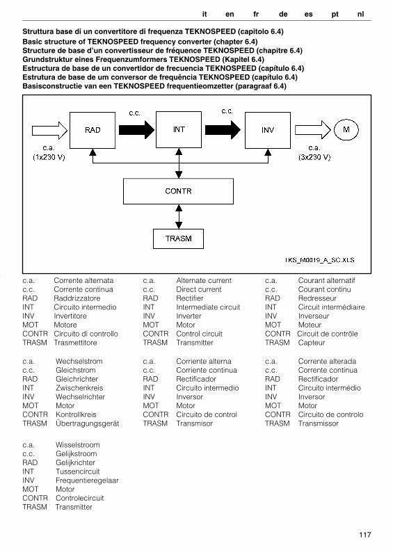
Struttura base di un convertitore di frequenza TEKNOSPEED (capitolo 6.4) Basic structure of TEKNOSPEED frequency converter (chapter 6.4)Structure de base d’un convertisseur de fréquence TEKNOSPEED (chapitre 6.4)Grundstruktur eines Frequenzumformers TEKNOSPEED (Kapitel 6.4)Estructura de base de un convertidor de frecuencia TEKNOSPEED (capítulo 6.4)Estrutura de base de um conversor de frequência TEKNOSPEED (capítulo 6.4)Basisconstructie van een TEKNOSPEED frequentieomzetter (paragraaf 6.4)
c.a. Corrente alternatac.c. Corrente continuaRAD RaddrizzatoreINT Circuito intermedioINV InvertitoreMOT MotoreCONTR Circuito di controlloTRASM Trasmettitore
c.a. Alternate currentc.c. Direct currentRAD RectifierINT Intermediate circuitINV InverterMOT MotorCONTR Control circuitTRASM Transmitter
c.a. Courant alternatif c.c. Courant continu RAD RedresseurINT Circuit intermédiaire INV Inverseur MOT MoteurCONTR Circuit de contrôleTRASM Capteur
c.a. Wechselstromc.c. GleichstromRAD GleichrichterINT ZwischenkreisINV WechselrichterMOT MotorCONTR KontrollkreisTRASM Übertragungsgerät
c.a. Corriente alternac.c. Corriente continuaRAD RectificadorINT Circuito intermedioINV InversorMOT MotorCONTR Circuito de controlTRASM Transmisor
c.a. Corrente alteradac.c. Corrente contínuaRAD RectificadorINT Circuito intermédioINV InversorMOT MotorCONTR Circuito de controloTRASM Transmissor
c.a. Wisselstroomc.c. GelijkstroomRAD GelijkrichterINT TussencircuitINV FrequentieregelaarMOT MotorCONTR ControlecircuitTRASM Transmitter
it en fr de es pt nl
118
it DICHIARAZIONE CE DI CONFORMITÁ « ORIGINALE »LOWARA SRL UNIPERSONALE, CON SEDE IN VIA LOMBARDI 14 - 36075 MONTECCHIO MAGGIORE (VI) - ITALIA, DICHIARA CHE IL PRODOTTO:
ELETTROPOMPE SERIE TKS(VEDETE ADESIVO SU PRIMA PAGINA)
E’ CONFORME ALLE DISPOSIZIONI DELLE SEGUENTI DIRETTIVE EUROPEE:• MACCHINE 2006/42/CE (IL FASCICOLO TECNICO È DISPONIBILE PRESSO LOWARA SRL UNIPERSONALE)• COMPATIBILITÁ ELETTROMAGNETICA 2004/108/CEE CONFORME ALLE SEGUENTI NORME TECNICHE:• EN 60335-2-41• EN ISO 12100• EN 809• EN 60204-1:2006• EN 61000-3-2:2006, EN 61000-3-3:2008• EN 61000-6-1:2007, EN 61000-6-3:2007
MONTECCHIO MAGGIORE, 03.05.2012AMEDEO VALENTE(DIRETTORE ENGINEERING e R&D)rev.00
frDÉCLARATION CE DE CONFORMITÉ « TRADUCTION »LOWARA SRL UNIPERSONALE, DONT LE SIÈGE EST SITUÉ 14 VIA LOMBARDI - 36075 MONTECCHIO MAGGIORE (VI) - ITALIE, DÉCLARE QUE LE PRODUIT:
ÉLECTROPOMPES SÉRIE TKS(VOIR L’AUTOCOLLANT SUR LA PREMIÈRE PAGE)
EST CONFORME AUX DISPOSITIONS DES DIRECTIVES EUROPÉENNES SUIVANTES:• MACHINES 2006/42/CE (LE DOSSIER TECHNIQUE EST DISPONIBLE AUPRÈS DE LOWARA SRL UNIPERSONALE)• COMPATIBILITÉ ÉLECTROMAGNÉTIQUE 2004/108/CEET EST CONFORME AUX NORMES TECHNIQUES SUIVANTES:• EN 60335-2-41• EN ISO 12100• EN 809• EN 60204-1:2006• EN 61000-3-2:2006, EN 61000-3-3:2008• EN 61000-6-1:2007, EN 61000-6-3:2007
MONTECCHIO MAGGIORE, 03.05.2012AMEDEO VALENTE(DIRECTEUR INGÉNIERIE ET R&D)rév.00
en EC DECLARATION OF CONFORMITY « TRANSLATION »LOWARA SRL UNIPERSONALE, WITH HEADQUARTERS IN VIA LOMBARDI 14 - 36075 MONTECCHIO MAGGIORE (VI) - ITALIA, HEREBY DECLARES THAT THE PRODUCT:
TKS ELECTRIC PUMP SERIES(SEE LABEL ON FIRST PAGE)
FULFILS THE RELEVANT PROVISIONS OF THE FOLLOWING EUROPEAN DIRECTIVES:• MACHINERY 2006/42/EC (THE TECHNICAL FILE IS AVAILABLE FROM LOWARA SRL UNIPERSONALE)• ELECTROMAGNETIC COMPATIBILITY 2004/108/ECAND THE FOLLOWING TECHNICAL STANDARDS:• EN 60335-2-41• EN ISO 12100• EN 809• EN 60204-1:2006• EN 61000-3-2:2006, EN 61000-3-3:2008• EN 61000-6-1:2007, EN 61000-6-3:2007
MONTECCHIO MAGGIORE, 03.05.2012AMEDEO VALENTE(DIRECTOR OF ENGINEERING AND R&D)rev.00
de EG-KONFORMITÄTSERKLÄRUNG « ÜBERSETZUNG »LOWARA SRL UNIPERSONALE, MIT SITZ IN VIA LOMBARDI 14 - 36075 MONTECCHIO MAGGIORE (VI) - ITALIEN, ERKLÄRT, DASS DIE NACHFOLGEND BESCHRIEBENEN PRODUKTE:
MOTORPUMPEN BAUREIHE TKS(SIEHE KLEBESCHILD AUF DER ERSTEN SEITE)
DEN VORSCHRIFTEN DER FOLGENDEN EUROPÄISCHEN RICHTLINIEN:• MACHINEN 2006/42/EG (DIE TECHNISCHE AKTE LIEGT BEI LOWARA SRL UNIPERSONALE AUF)• ELEKTROMAGNETISCHE KOMPATIBILITÄT 2004/108/EGSOWIE DEN FOLGENDEN TECHNISCHEN VORSCHRIFTEN ENTSPRECHEN:• EN 60335-2-41• EN ISO 12100• EN 809• EN 60204-1:2006• EN 61000-3-2:2006, EN 61000-3-3:2008• EN 61000-6-1:2007, EN 61000-6-3:2007
MONTECCHIO MAGGIORE, 03.05.2012AMEDEO VALENTE(LEITER TECHNIK UND R&D)rev.00
119
esDECLARACIÓN CE DE CONFORMIDAD « TRADUCCIÓN »LOWARA SRL UNIPERSONALE, CON SEDE EN VIA LOMBARDI 14 - 36075 MONTECCHIO MAGGIORE (VI) - ITALIA, DECLARA QUE EL PRODUCTO:
ELECTROBOMBAS SERIE TKS(VEA EL ADHESIVO EN LA PRIMERA PÁGINA)
ES CONFORME A LA DISPOSICIONES DE LAS SIGUIENTES DIRECTIVAS EUROPEAS: • MÁQUINAS 2006/42/CE (EL EXPEDIENTE TÉCNICO ESTÁ DISPONIBLE EN LOWARA SRL UNIPERSONALE)• COMPATIBILIDAD ELECTROMAGNÉTICA 2004/108/CEY ES CONFORME A LAS NORMAS TÉCNICAS SIGUIENTES:• EN 60335-2-41• EN ISO 12100• EN 809• EN 60204-1:2006• EN 61000-3-2:2006, EN 61000-3-3:2008• EN 61000-6-1:2007, EN 61000-6-3:2007
MONTECCHIO MAGGIORE, 03.05.2012AMEDEO VALENTE(DIRECTOR ENGINEERING Y R&D)rev.00
nl EG-VERKLARING VAN OVEREENSTEMMING « VERTALING »DE FIRMA LOWARA SRL UNIPERSONALE, GEVESTIGD IN VIA LOMBARDI 14 - 36075 MONTECCHIO MAGGIORE (VI) - ITALIË, VERKLAART DAT HET PRODUCT:
ELEKROPOMPEN TKS SERIE(ZIE DE STICKER OP DE EERSTE BLADZIJDE)
IN OVEREENSTEMMING IS MET DE BEPALINGEN VAN DE VOLGENDE EUROPESE RICHTLIJNEN:• MACHINERICHTLIJN 2006/42/EG (HET TECHNISCH DOSSIER IS BESCHIKBAAR BIJ LOWARA SRL UNIPERSONALE) • ELEKTROMAGNETISCHE COMPATIBILITEITSRICHTLIJN 2004/108/EGEN DE VOLGENDE TECHNISCHE NORMEN:• EN 60335-2-41• EN ISO 12100• EN 809• EN 60204-1:2006• EN 61000-3-2:2006, EN 61000-3-3:2008• EN 61000-6-1:2007, EN 61000-6-3:2007
MONTECCHIO MAGGIORE, 03.05.2012AMEDEO VALENTE(DIRECTEUR VAN ENGINEERING EN R&D)rev.00
ptDECLARAÇÃO CE DE CONFORMIDADE « TRADUÇÃO »A LOWARA SRL UNIPERSONALE, COM SEDE EM VIA LOMBARDI 14 - 36075 MONTECCHIO MAGGIORE (VI) - ITÁLIA, DECLARA QUE O PRODUTO:
ELECTROBOMBAS SÉRIE TKS(VER O ADESIVO NA PRIMEIRA PÁGINA)
ESTÁ EM CONFORMIDADE COM AS DISPOSIÇÕES DAS SEGUINTES DIRECTIVAS EUROPEIAS:• MÁQUINAS 2006/42/CE (O DOSSIER TÉCNICO ESTÁ À DISPOSIÇÃO JUNTO DE LOWARA SRL UNIPERSONALE)• COMPATIBILIDADE ELECTROMAGNÉTICA 2004/108/CEE EM CONFORMIDADE COM AS SEGUINTES NORMAS TÉCNICAS:• EN 60335-2-41• EN ISO 12100• EN 809• EN 60204-1:2006• EN 61000-3-2:2006, EN 61000-3-3:2008• EN 61000-6-1:2007, EN 61000-6-3:2007
MONTECCHIO MAGGIORE, 03.05.2012AMEDEO VALENTE(DIRECTOR ENGINEERING E R&D)rev.00
it Lowara si riserva il diritto di apportare modifiche senza obbligo di preavviso. en Lowara reserves the right to make modifications without prior notice. fr Lowara se réserve le droit d’apporter des modifications sans obligation de préavis. de Änderungen, auch ohne vorherige Ankündigung, sind LOWARA jederzeit vorbehalten. es Lowara se reserva el derecho de realizar modificaciones sin necesidad de aviso previo. pt A Lowara reserva-se o direito de proceder a alterações sem aviso prévio. nl Lowara behoudt zich het recht voor om zonder voorafgaand bericht wijzigingen aan te brengen. da Lowara forbeholder sig retten til at ændre specifikationerne uden meddelelse herom. no Lowara forbeholder seg retten til å utføre endringer uten forvarsel. sv Lowara förbehåller sig rätten att utföra ändringar utan förhandsmeddelande. fi Lowara pidättää itselleen oikeuden tehdä muutoksia ilman ennakkoilmoitusta. is Lowara áskilur sér rétt til að gera breytingar án fyrirvara. et Lowara jätab endale õiguse teha muudatusi eelnevalt ette teatamata lv Lowara patur tiesības veikt izmaiņas bez iepriekšēja brīdinājuma. lt „Lowara“ pasilieka teisę atlikti pakeitimus be išankstinio įspėjimo. pl Lowara zastrzega sobie prawo do wprowadzenia zmian bez obowiązku wcześniejszego powiadomienia. cs Společnost Lowara si vyhrazuje právo na provedení změn bez předcházejícího upozornění. sk Spoločnosť Lowara si vyhradzuje právo na vykonanie zmien bez predchádzajúceho upozornenia. hu A Lowara fenntartja magának a jogot előzetes értesítés nélküli módosítások eszközlésére. ro Lowara îşi rezervă dreptul de a face modificări fără o înştiinţare prealabilă. bg Фирмата Ловара си запазва правото да нанася промени без предупреждение sl Lowara si pridržuje pravico do vnašanja sprememb brez vsakršnega predhodnega obvestila. hr Lowara zadržava pravo promjene bez obveze prethodne najave. sr Lowara zadržava pravo promene bez obaveze prethodne najave. el Η Lowara διατηρεί το δικαίωμα να επιφέρει τροποποιήσεις χωρίς υποχρέωση προειδοποίησης tr Lowara şirketi önceden haber vermeksizin değişiklikler yapma hakkn sakl tutmaktadr ru Lowara оставляет за собой право вносить изменения без предварительного уведомления. uk Компанія Lowara залишає за собою право вносити зміни без попередження. ar تحتفظ شرآة لواراLowaraبحق إجراء تعديالت بدون االلتزام بالتنبيه الُمسبق .
Headquarters LOWARA S.R.L. UNIPERSONALE Via Vittorio Lombardi 14 36075 Montecchio Maggiore VI Italia Tel. (+39) 0444 707111 - Fax (+39) 0444 492166 e-mail: [email protected] web: www.lowara.com
© 2011 Xylem, Inc