Embed Size (px)
Citation preview


Universidade do Minho
Escola de Engenharia
José Eduardo Moreira Fernandes
About Model-Based Approaches in
Pervasive Information Systems
Development
Tese de Doutoramento
Grau de Doutor em Tecnologias e Sistemas de
Informação
Área de Conhecimento em Engenharia da Programação
e dos Sistemas Informáticos
Trabalho efectuado sob a orientação de
Professor Doutor Ricardo J. Machado
Professor Doutor João Álvaro Carvalho
Outubro de 2010

É AUTORIZADA A REPRODUÇÃO INTEGRAL DESTA TESE/TRABALHO APENAS
PARA EFEITOS DE INVESTIGAÇÃO, MEDIANTE DECLARAÇÃO ESCRITA DO
INTERESSADO, QUE A TAL SE COMPROMETE.
Universidade do Minho, 29/ 10 / 2010
Assinatura: ________________________________________________
iii
Agradecimentos
Aos meus pais António e Emília. Não há palavras ou imagens que cheguem para expressar o
quanto deles recebi nem para lhes expressar o meu reconhecimento, a minha gratidão e o meu
carinho. Ao meu irmão Sérgio e à minha querida Alice pelo suporte, atenção e solidariedade
neste meu esforço.
Aos meus orientadores Prof. Doutor João Álvaro Carvalho e Prof. Doutor Ricardo Machado por
todo o apoio e amizade. Um agradecimento especial para o Prof. Doutor Ricardo Machado, um
amigo que, com o seu esforço, a sua paciência e a sua disponibilidade, me deu o incentivo, a
orientação, o ânimo e o exemplo.
À Escola Superior de Tecnologia e de Gestão de Bragança e ao Instituto Politécnico de
Bragança pela oportunidade concedida para a realização deste doutoramento.
A todos estes e a todos aqueles que, de forma muito especial, participaram neste percurso da
minha vida contribuindo para que este trabalho chegasse a bom termo, um sincero abraço, e um
muito obrigado.
Apoio Financeiro
Este trabalho foi desenvolvido com o apoio do programa PRODEP, e do Instituto Politécnico de
Bragança, através da sua Escola Superior de Tecnologia e de Gestão.
UNIÃO EUROPEIA
Fundo Social Europeu


v
Abstract
Ubiquitous computing is a research field of computing technology with a growing number
of researchers and represents a new direction on the thinking about the integration and
use of computers in people’s lives. It aims to achieve a new computing paradigm, one in
which there is a high degree of pervasiveness and widespread availability of computers or
other IT devices, usually with communication capabilities, in the physical environment.
Model-Driven Development (MDD) constitutes an approach to software design and
development that strongly focuses and relies on models, through which we build
software-platform independent models. Several contributions of MDD are: gains of
productivity; concepts closer to domain and reduction of semantic gap; automation and
less sensitivity to technological changes; and capture of expert knowledge and reuse.
This thesis aims to contribute for the appropriate use of model-based/driven
development approaches in software development for pervasive information systems
(PIS). This work considers a case study research strategy. It uses two projects developed
in the field of ubiquitous and mobile computing that directed their software development
to a model-based/driven approach.
This thesis describes and analyses the projects. Each one of the project is formalized in a
SPEM 2.0 model that presents the main elements of the project. This SPEM model allows
perceiving the structure and elements of the project, along with some issues and facts of
the project. This thesis conceives a development framework that introduces several
useful conceptions. Among these conceptions are the dimensions of development,
functional profiles, resources categories, functional profile instances, global and
elementary development process. In consonance with this development framework, the
thesis proposes a SPEM 2.0 Base Plug-In extension and a development framework pattern
to assist in the analysis of the projects. The SPEM 2.0 Base Plug-In extension defines
elements that are fundamental to the definition and application of the development
framework pattern. The development framework pattern is applied to each of the
projects to facilitate the analysis. From the analysis of the projects, the thesis synthesizes
a set of guidelines and insight related to the adoption of model-based/driven approaches
to pervasive information system development.
Keywords: Pervasive Information Systems, PIS, Model-Driven Development, MDD, SPEM, Development Framework Pattern, Case Studies.

vii
Resumo
A computação ubíqua é um campo de investigação de tecnologia de computação com um
número crescente de investigadores e representa uma nova direcção no pensamento
sobre a integração e o uso de computadores na vida das pessoas. O objectivo é alcançar
um novo paradigma de computação em que há um alto grau de abrangência e ampla
disponibilidade de computadores ou outros dispositivos de tecnologias de informação,
geralmente com recursos de comunicação, no ambiente físico.
Model-Driven Development (MDD), constitui uma abordagem de desenho e
desenvolvimento de software que se baseia em modelos, através da qual construímos
modelos de plataforma de software independentes. Várias contribuições de MDD são:
ganhos de produtividade; conceitos mais próximos ao domínio e à redução do salto
semântico; automação e menor sensibilidade às mudanças tecnológicas; captura de
conhecimento especializado e reutilização.
Esta tese visa contribuir para a adequada utilização de abordagens de desenvolvimento
baseadas/conduzidas por modelos no desenvolvimento de software para sistemas de
informação “pervasive” (PIS). Esta tese apresenta uma estratégia de investigação de
estudo de caso. Usa, como estudos de caso, dois projectos desenvolvidos no campo da
computação ubíqua e móvel, e os quais dirigiram o seu desenvolvimento de software
para uma abordagem baseada/conduzida por modelos.
Esta tese descreve e analisa os projectos; cada um dos projectos é formalizado num
modelo SPEM 2.0 que apresenta os elementos principais do projecto. Este modelo SPEM
permite perceber a estrutura e os elementos do projecto, juntamente com alguns
problemas e factos do projecto. Esta tese concebe uma estrutura de desenvolvimento
que apresenta várias concepções úteis. Entre essas concepções estão as dimensões de
desenvolvimento, os perfis funcionais, as categorias de recursos, instâncias de perfil
funcional, os processos de desenvolvimento global e elementar. Em consonância com
esta estrutura de desenvolvimento, a tese propõe uma extensão ao SPEM 2.0 Base Plug-
In e um padrão de desenvolvimento para auxiliarem a análise dos projectos. A extensão
ao SPEM 2.0 Base Plug-In define elementos que são fundamentais para a definição e
aplicação do padrão de estrutura de desenvolvimento. O padrão de estrutura de
desenvolvimento é aplicado a cada um dos projectos para facilitar a sua análise. A partir
da análise dos projectos, a tese sintetiza um conjunto de directrizes e de ilações
relacionadas com a adopção de abordagens MDD para o desenvolvimento de PIS.
Palavras-chave: Pervasive Information Systems, PIS, Model-Driven Development, MDD, SPEM, Development Framework Pattern, Case Studies.


ix
Table of Contents
Chapter 1 ...................................................................................................................................................... 1
1 Introduction .................................................................................................................................. 3
1.1 Pervasive Systems ......................................................................................................................... 3
1.2 Methodological Challenges ........................................................................................................... 9
1.3 Goals and Research Strategy ...................................................................................................... 10
1.4 Contributions .............................................................................................................................. 14
1.5 Structure of this Document......................................................................................................... 14
Chapter 2 .................................................................................................................................................... 17
2 Pervasive Computing ................................................................................................................... 19
2.1 Introduction ................................................................................................................................ 19
2.2 A New Computing Paradigm ....................................................................................................... 21
2.3 Business Opportunities and Social Concerns .............................................................................. 27
2.4 Pervasive Information Systems ................................................................................................... 38
2.5 Conclusion ................................................................................................................................... 42
Chapter 3 .................................................................................................................................................... 45
3 Model-Driven Development ........................................................................................................ 47
3.1 Introduction ................................................................................................................................ 47
3.2 Models in Software Development .............................................................................................. 48
3.3 Model-Driven Architecture ......................................................................................................... 55
3.4 Research Efforts .......................................................................................................................... 64
3.5 Conclusion ................................................................................................................................... 68
Chapter 4 .................................................................................................................................................... 69
4 Presentation of the Projects........................................................................................................ 71
4.1 Introduction ................................................................................................................................ 71
4.2 Presentation of the uPAIN Project .............................................................................................. 73
4.2.1 The Pervasive Perspective ................................................................................................... 74
4.2.2 The Modelling Perspective .................................................................................................. 75
4.3 Presentation of the USE-ME.GOV Project ................................................................................... 81
4.3.1 The Pervasive Perspective ................................................................................................... 84
4.3.2 The Modelling Perspective .................................................................................................. 84
4.4 Common Facts, Issues and Challenges ........................................................................................ 95
4.5 Conclusion ................................................................................................................................... 97
Chapter 5 .................................................................................................................................................... 99
5 Approach to PIS Development .................................................................................................. 101
5.1 Introduction .............................................................................................................................. 101
5.2 Development Dimensions and Framework ............................................................................... 104
5.2.1 Resources Dimension ........................................................................................................ 104
5.2.2 Functional Dimension........................................................................................................ 105
5.2.3 Abstraction Dimension ...................................................................................................... 108
5.2.4 Development Framework ................................................................................................. 110
5.3 Extension to SPEM 2.0 Base Plugin Profile ................................................................................ 114
5.4 Approach to Software Development of PIS .............................................................................. 117
5.5 Conclusion ................................................................................................................................. 128
x
Chapter 6 .................................................................................................................................................. 131
6 Analysis of the Projects ............................................................................................................. 133
6.1 Introduction .............................................................................................................................. 133
6.2 Analysis of uPAIN Project .......................................................................................................... 134
6.2.1 Pictorial Description of Major Activities and Deliverables ................................................ 135
6.2.2 SPEM 2.0-Based Description of Activities and Artefacts ................................................... 136
6.2.3 Development Framework Pattern .................................................................................... 141
6.3 Analysis of USE-ME.GOV Project ............................................................................................... 144
6.3.1 Pictorial Description of Major Activities and Deliverables ................................................ 144
6.3.2 SPEM 2.0-Based Description of Activities and Artefacts ................................................... 146
6.3.3 Development Framework Pattern .................................................................................... 154
6.4 Lessons Learned ........................................................................................................................ 160
6.5 Conclusion ................................................................................................................................. 164
Chapter 7 .................................................................................................................................................. 165
7 Conclusion ................................................................................................................................. 167
7.1 Focus of the Work ..................................................................................................................... 167
7.2 Synthesis of Research Efforts .................................................................................................... 169
7.3 Synthesis of Scientific Results ................................................................................................... 170
7.4 Future Work .............................................................................................................................. 172
References ........................................................................................................................................... 175

xi
Acronyms
FP Functional Profile
DS Development Structure
MDA Model-Driven Architecture
MDD Model-Driven Development
MOF Meta-Object Facility
OMG Object Management Group
PDA Personal Digital Assistant
PIM Platform-Independent Models
PIS Pervasive Information Systems
PSM Platform-Specific models
SDLC System Development Life Cycle
SPEM Software & Systems Process Engineering Meta-Model Specification
UML Unified Modelling Language
uPAIN Ubiquitous Solutions for Pain Monitoring and Control in Post-Surgery Patients
USE-ME.GOV USability-drivEn open platform for MobilE GOVernment
XMI XML Metadata Interchange


xiii
Table of Figures
Figure 1.1 - The Apple iPAD(Apple, 2010) . ................................................................................................ 8 Figure 1.2 - The Samsung Galaxy Tab(Samsung, 2010) . ............................................................................ 8 Figure 1.3 - The general methodology of design science research ((Vaishnavi & Jr., 2008)). .................. 13 Figure 2.1 – Research agenda for pervasive computing (adapted from (Satyanarayanan, 2001)). ......... 20 Figure 2.2 - Traditional, Mobile, Pervasive and Ubiquitous Computing (extracted from (Lyytinen &
Yoo, 2002)). ...................................................................................................................................... 25 Figure 2.3- The VeriChip (extracted from (Verichip, 2006a)). .................................................................. 34 Figure 3.1- Raising the level of abstraction (extracted from (Miller, et al., 2004a)) ................................ 49 Figure 3.2 - The modelling spectrum (adapted from (Brown, 2004)). .................................................... 50 Figure 3.3 - The system development cycle process (adapted from [Alhir, 2003]) ................................. 57 Figure 3.4 - Foundational Concepts on the MDA (adapted from [Alhir, 2003]). ..................................... 58 Figure 3.5 - MDA core concepts. .............................................................................................................. 58 Figure 3.6 - How MDA is to be used. ........................................................................................................ 60 Figure 3.7 - Model type mappings. .......................................................................................................... 61 Figure 3.8 - Model instance mappings. .................................................................................................... 62 Figure 3.9 - Templates in model type mappings. ..................................................................................... 63 Figure 3.10 - Templates with an associated set of marks. ....................................................................... 63 Figure 3.11 - Model transformation. ....................................................................................................... 64 Figure 3.12 - Direct transformation to code. ........................................................................................... 65 Figure 4.1 - General architecture for the uPAIN system. ......................................................................... 74 Figure 4.2 - Level 0 Use Case diagram for uPAIN (from (uPAIN, 2005a)). ................................................ 75 Figure 4.3 - Use case refined diagram for the “Administer Drug” use case (from (uPAIN, 2005a)). ....... 76 Figure 4.4 - UML stereotyped sequence diagram for a uPAIN use case macro-scenario (from(uPAIN,
2005a)) ............................................................................................................................................. 76 Figure 4.5 - Interactive animation prototype for uPAIN system (from (Machado, et al., 2007) .............. 77 Figure 4.6 - CPN responsible for the prototype animation of a use case (from (Machado, et al., 2007)).
......................................................................................................................................................... 78 Figure 4.7 - Transformation of messages (uPAIN, 2005b). ..................................................................... 79 Figure 4.8 - Transformation of an alternative block (uPAIN, 2005b)). ..................................................... 79 Figure 4.9 - 4SRS Technique (adapted from (J. Fernandes & Machado, 2001)) ...................................... 80 Figure 4.10 - uPAIN logical architecture. ................................................................................................. 81 Figure 4.11 - Situation before USE-ME.GOV (USE-ME.GOV, 2003b). ...................................................... 82 Figure 4.12- Situation after USE-ME.GOV(USE-ME.GOV, 2003b). ........................................................... 82 Figure 4.13 - USE-ME.GOV System General Architecture (from (USE-ME.GOV, 2006)) .......................... 83 Figure 4.14 - User mobile access through cellular networks (adapted from (USE-ME.GOV, 2004b)) ..... 84 Figure 4.15 - Use cases for service Report of Complaints ((USE-ME.GOV, 2004d)) ................................. 86 Figure 4.16 - Activity diagram for service (Report of Complaints ((USE-ME.GOV, 2004d)). .................... 86 Figure 4.17 - Level zero use case diagram by criteria of main functionalities. ........................................ 88 Figure 4.18 - Level zero use case diagram by criteria of application domain. ......................................... 88 Figure 4.19- Level one use case diagram of "send alert" use case. ......................................................... 88 Figure 4.20 - USE-ME.Gov raw diagram (part of). .................................................................................... 89 Figure 4.21 - Sequence diagram for citizen making a Complaint in the “Citizen Complaint Service”
(USE-ME.GOV, 2004k). ..................................................................................................................... 89 Figure 4.22 - Part of the “Report of Complaints Service” requirements (USE-ME.GOV, 2004e). ............ 90 Figure 4.23 - High-level USE-ME.GOV diagram(USE-ME.GOV, 2004b) .................................................... 90 Figure 4.24 - Sequence diagram "Make complaint” (USE-ME.GOV, 2004b). ........................................... 91 Figure 4.25 - User Management use cases. ............................................................................................. 92 Figure 4.26 - Subscription states. ............................................................................................................. 92

xiv
Figure 4.27 - Authenticate User activities diagram. ................................................................................ 92 Figure 4.28 – Use case model for Service Provision. ............................................................................... 93 Figure 4.29 - Use case model for Service Authentication. ....................................................................... 93 Figure 4.30 - Use case model for Service Authorization. ......................................................................... 93 Figure 4.31 - High-level Service diagram (USE-ME.GOV, 2004g). ............................................................ 93 Figure 4.32 - Service Architecture diagram (USE-ME.GOV, 2004g). ........................................................ 93 Figure 4.33 - Platfom interfaces to implement (USE-ME.GOV, 2004g). .................................................. 93 Figure 4.34 - Main menu user interface (USE-ME.GOV, 2004g). ............................................................. 93 Figure 4.35 - Data model diagram (USE-ME.GOV, 2004g). ...................................................................... 93 Figure 4.36 - USE-ME.GOV System General Architecture. ....................................................................... 94 Figure 4.37 - Service Repository General Architecture............................................................................ 94 Figure 4.38 - Core Platform Layers View. ................................................................................................ 94 Figure 4.39 - Class diagram for HTTP Server Adapter(Layer 1) ............................................................... 95 Figure 4.40 - Sequence diagram for doGet request of HTTPServerInterface. ......................................... 95 Figure 5.1 – Resources dimension. ........................................................................................................ 104 Figure 5.2 - Functional dimension. ........................................................................................................ 105 Figure 5.3 – Framing of Resources and Functional dimensions. ........................................................... 106 Figure 5.4 –Example of functional profiles Instances for resource categories. ..................................... 107 Figure 5.5 - Development structures for functional profile instances. .................................................. 108 Figure 5.6 - Structure of PIMs and PSMs inherent to the previous resources’s classification. ............. 109 Figure 5.7 - Illustration of the abstraction process. ............................................................................... 110 Figure 5.8 - Direct code generation. ...................................................................................................... 110 Figure 5.9 – Example of a horizontal model mapping. .......................................................................... 111 Figure 5.10 - Dimensions on the development approach. .................................................................... 111 Figure 5.11 - Macro Process Milestones, Phases, and Iterations (from (Booch, et al., 2007)). ............. 111 Figure 5.12 - The Micro Process within the Macro Process (from (Booch, et al., 2007)). ..................... 112 Figure 5.13 - Development framework for PIS. ..................................................................................... 113 Figure 5.14 – Inclusion of new Activity Kinds. ....................................................................................... 116 Figure 5.15 - Inclusion of new Artefacts Kinds. ..................................................................................... 116 Figure 5.16 - Crossing conceptions. ....................................................................................................... 119 Figure 5.17 - Framing structure for a project. ....................................................................................... 120 Figure 5.18 - Rearrangement of a project’s SPEM model. ..................................................................... 120 Figure 5.19 - Synthesis of extending SPEM stereotypes. ....................................................................... 120 Figure 5.20 - PIS development framework pattern. .............................................................................. 123 Figure 5.21 - Pattern realization SPEM 2.0 model. ................................................................................ 125 Figure 5.22 - Nesting of framing structures for huge projects. ............................................................. 126 Figure 5.23 - 4SRS model transformation technique under a SPEM 2.0 perspective. ........................... 127 Figure 6.1 - Phases of uPAIN project. .................................................................................................... 134 Figure 6.2 - Major results in Project Management, Exploration and Evaluation of the Application, and
Medical Research phases of the uPAIN project. ............................................................................ 135 Figure 6.3 - Major results in Requirements Analysis and Elicitation phase of the uPAIN project. ........ 135 Figure 6.4 - Major results in Research and Technological Development phase of the uPAIN project. . 136 Figure 6.5 - uPAIN development process under a SPEM 2.0 perspective. ............................................ 137 Figure 6.6 - SPEM 2.0 diagram of the phase “Requirements Analysis and Elicitation" of uPAIN project.
....................................................................................................................................................... 138 Figure 6.7 - SPEM 2.0 diagram of the phase “Research and Technological Development" of uPAIN
project (part 1of 2). ....................................................................................................................... 139 Figure 6.8 - SPEM 2.0 diagram of the phase “Research and Technological Development" of uPAIN
project (part 2of 2). ....................................................................................................................... 140 Figure 6.9 - SPEM 2.0 diagram of the phases “Project Management”, “Exploitation and Application
Evaluation”, and “Medical Research” of uPAIN project. ............................................................... 140 Figure 6.10 - Framing structure for uPAIN project. ............................................................................... 141 Figure 6.11 – uPAIN’s restructured SPEM diagram (major structuring elements). ............................... 142 Figure 6.12 - uPAIN’s restructured SPEM diagram (transformations and elementary process activities).
....................................................................................................................................................... 143
xv
Figure 6.13 - USE-ME.GOV major development efforts. ........................................................................ 144 Figure 6.14 - Deliverables in Implementation and Integration, in Validation, and in Recommendations.
....................................................................................................................................................... 144 Figure 6.15 - Deliverables for Service Scenario Definitions and Evaluation. ......................................... 145 Figure 6.16- Deliverables in Requirements Analysis. ............................................................................. 145 Figure 6.17 – Deliverables in Preliminary Design and Mock-up. ........................................................... 145 Figure 6.18 - Deliverables in Detailed Design and Specification. ........................................................... 146 Figure 6.19 - Deliverables in Implementation and Integration. ............................................................. 146 Figure 6.20- USE-ME.GOV development process under a SPEM 2.0 perspective. ................................ 147 Figure 6.21 - SPEM 2.0 perspective over Service Scenario Definitions and Evaluation in USE-ME.GOV.
....................................................................................................................................................... 148 Figure 6.22 - SPEM 2.0 perspective over Requirements Analysis in USE-ME.GOV. ............................... 149 Figure 6.23 - SPEM 2.0 perspective over Preliminary Design and Mock-Up in USE-ME.GOV. ............... 150 Figure 6.24 - SPEM 2.0 perspective over Detailed Design and Specification in USE-ME.GOV. .............. 151 Figure 6.25 - SPEM 2.0 perspective over Implementation and Integration in USE-ME.GOV. ................ 152 Figure 6.26 - SPEM 2.0 perspective over Validation in USE-ME.GOV. ................................................... 153 Figure 6.27 - SPEM 2.0 perspective over Project Planning, Recommendations, and Dissemination in
USE-ME.GOV. ................................................................................................................................. 153 Figure 6.28 - Framing structure at system level for USE-ME.GOV project. ........................................... 155 Figure 6.29 - Functional profile instance for Platform subsystem. ........................................................ 155 Figure 6.30 - Framing structure for Pilot Services subsystem of USE-ME.GOV. .................................... 156 Figure 6.31 - USE-ME.GOV’s restructured SPEM diagram (major structuring elements at system level).
....................................................................................................................................................... 157 Figure 6.32 - USE-ME.GOV restructured SPEM diagram (major structuring elements at Platform
subsystem level)............................................................................................................................. 158 Figure 6.33 - USE-ME.GOV’s restructured SPEM diagram (major structuring elements at Pilot Services
subsystem level)............................................................................................................................. 159 Figure 6.34 – Models, model mappings/transformations, and code generation in the development of
the uPAIN system. .......................................................................................................................... 162


xvii
List of Tables
Table 2.1 - Appropriate usage of terms pervasive and ubiquitous. ......................................................... 27 Table 5.1 - Tasks for pattern realization. ............................................................................................... 124 Table 5.2 - Main concepts of the proposed approach to the development PIS. ................................... 129


Chapter 1
Introduction
Chapter Contents
1 Introduction ............................................................................................................................................. 3
1.1 Pervasive Systems ............................................................................................................................. 3
1.2 Methodological Challenges ............................................................................................................... 9
1.3 Goals and Research Strategy ........................................................................................................... 10
1.4 Contributions .................................................................................................................................. 14
1.5 Structure of this Document ............................................................................................................. 14

2

3
1
Introduction
This chapter starts by introducing the research areas subjacent to this thesis, namely
ubiquitous computing and model-driven development. The chapter goes on by
presenting the methodological research followed. It concludes with the main
contributions achieved.
1.1 Pervasive Systems
Since the introduction of the transistor in 1947 by John Bardeen, Walter Brattain, and William
Shockley at Bell Labs (Bell Labs), the integrated circuit in 1958 by Jack Kilby at Texas
Instruments (Texas Instruments), and the Intel first microprocessor in
1971 (the 4004 microprocessor (Intel)), technological developments in miniaturization,
integration and capabilities’ enhancement of electronic components have been noticed by its
outstanding achievements.
From the mainframe era (characterized by rare, enormous, and expensive machines that
were difficult to access, usually only possessed only by large institutions and shared by many
people), succeeded the era of the widely available personal computer (one computer for one
person). Simultaneously, the emergence of the Internet, interconnecting all of those
machines and enabling for worldwide share of information and computational capabilities,
new services and business models, and easier and improved people interaction, further
enhanced the value and social acceptance of computing.

1 Introduction
4
These technological developments, along with its social acceptance and business recognition
of its value, have been major facilitators for adoption of means for structured and automated
acquisition, storage, and processing of information along with improved ways for easier and
faster access to that information. In context of competition, the recognition of information
as a fundamental resource to individuals and organizations, and of the usefulness of the
abilities information technology (IT) devices, stimulated the search for enhancement and
innovation of existing services and for envisioning new ones. Such quest has led to not only
widespread adoption and sophistication of information systems that are nowadays seen as
vital to the existence of modern services and business models, but also to further research
for technology improvements and innovations.
New technologies and techniques, along with further miniaturization and reduction of costs,
fostered the dissemination of computing. Notable advances were achieved in portability and
the embedding of computers, in sensors/actuators, storage capacity, wireless
communications technology and in novel modalities of human-computer interaction. As
consequence, today we can find computing and communications technology in places,
objects, animals or even people. This allows for new possibilities of interaction between
people and their physical environment, or among people themselves. The once troublesome
and frequently unpleasant one-to-many computer-human relationship evolved through a
one-to-one relationship of personal computing, to today’s many-to-one relationship that is
more convenient and seamlessly integrated in our way of life (Weiser & Brown, 1997).
Ubiquitous computing
Ubiquitous computing1 is a research field of computing technology with a growing number of
researchers and represents a new direction on the thinking about the integration and use of
computers in people’s lives. It aims to achieve a new computing paradigm, one in which there
is a high degree of pervasiveness and widespread availability of computers or other IT
devices, usually with communication capabilities, in the physical environment. As such,
besides our traditional and current computers, computing devices are embedded in physical
places and objects (static or mobile), being these (usually wirelessly) interconnected.
Ubiquitous computing research was introduced in the 90s by Mark Weiser, a primordial
reference in the ubiquitous computing field. In 1991, Weiser published his widely recognized
and referenced seminal work on ubiquitous computing, “The Computer for the 21st Century”
(Weiser, 1991), in which he shared his vision of a new way of thinking about computers.
1 in today terminology, the term “pervasive” is also used, sometimes interchangeably, with the same meaning of “ubiquitous”.

1.1 Pervasive systems
5
Weiser envisioned a future computing on which computers were embedded in everyday
objects and places, enhancing its purpose and thus allowing for an enrichment of the physical
world with the advantages of processing power, storage, and communications of computers.
Ubiquitous computing doesn’t simply restrict to the widespread pervasiveness of computers;
it proposes a new computing paradigm of which philosophy values the nuances of the real
world, and embodies the assumption that computers, should fade into the physical
environment in a “virtual or effective” invisible way to people (Weiser, 1993a). While
computationally enriching the environment, computers shall offer a permanent and non-
intrusive computing that seamlessly support and help people to focus fully on completion of
the tasks needed to the prosecution of their desired goals.
This computational augmentation of objects and places, and the subsequent enriched
interaction with people, follows the principle of an “invisible computing” that “engenders
calmness”: (i) “invisible”, in the sense that computers, as part of a context of use, become
integrated and faded with our environment; (ii) “computing that engenders calmness”, in the
sense that computers and computing don’t need our permanent active attention for
continuous operation and readiness to easy information access (they lie in the “periphery”
(Weiser & Brown, 1997), easily moving to the centre of our attention only when needed). In
this way, it would become possible to allow people to use them without focusing for such
use, and so, to focus beyond them on new goals.
Giving the “literacy technology” (the ability to capture a symbolic representation of spoken
language) as an example of a ubiquitous technology, Weiser also stated that invisibleness of
computers is “…a fundamental consequence not of technology, but of human psychology. Whenever people learn
something sufficiently well, they cease to be aware of it” (Weiser, 1991). Computers, as a tool, should not
need conscious interaction to it as such; instead, they should be as unobtrusive as possible,
permanently allowing and assisting people on their tasks. Weiser exemplified: eyeglasses
don’t need permanent active attention to use them; we look at what is in front of us, and not
at the eyeglasses (Weiser, 1994).
This notion of ubiquitous computing was also described as “perhaps (…) opposed” (Weiser, 1991)
to the notion of virtual reality; the latter, attempting to make a world inside a computer,
focuses on simulating a world, and the former, focuses on the invisible enhancing of the
physical world that already exists. Ubiquitous computing also embodies a philosophy
opposed to the current approach to computing that places the computer as the fundamental
element to the human attention.

1 Introduction
6
Weiser also stated that “The real power of the concept comes not from any of these devices; it emerges from the
interaction of all them” (Weiser, 1991). In fact, the individual device does not allow by itself to
obtain the maximum exploration of its capabilities or even to allow for ubiquitous computing.
Only in interaction with other devices, ubiquitous computing can be sustained and full
exploration of device’s capabilities can be achieved, allowing for availability of the
information collected and processed.
Weiser established (Weiser, 1991) the major parts of technology needed for realizing for
ubiquitous computing (“cheap, low-power computers that include equally convenient displays”, “networks that ties
all of them together” and “software systems implementing ubiquitous applications.”). He identified (Weiser,
1991; Weiser, 1993b) technological development needs and first issues of importance to be
attended (such as location2, scale3 and privacy ) and provided a description of how devices
could be used to work, in the context of ubiquitous computing, to improve peoples’ work and
life. Considering the campus environment a “particularly good place for ubiquitous computing” (Weiser,
1998), Weiser exemplified applications of ubiquitous computing on campus and reinforced
the key concept of engendering calmness. In (Russell & Weiser, 1998), it can be found several
challenges to the design of ubiquitous systems, concerning the infrastructure, user interface
and user experiences.
At Xerox PARC (PARC, 2004), in 1988, it was created the Ubiquitous Computing research
program that, including several fields of computer science, had at its core the ubiquitous
computing basic key ideas. The program was inspired by this new paradigm (considered
different from the then current predominant “one person – one computer”) that assumed an
emphasis not in the particular characteristics of computers (such as memory and processor
speed), but in the use of computer technology in support of daily activity and its appropriate
integration in the physical environment. It was first envisioned as a “radical answer to what was
wrong with the personal computer: too demanding of attention; too isolating from other people and activities; and too
dominating as it colonized our desktops and our lives” (Weiser, Gold, & Brown, 1999).
The research program members at Xerox PARC, as Roy Want (Want et al., 1995), prototyped
several systems and demonstrated, with the technology then available, their utility in this
philosophy of ubiquitous computing (Want, 2000). Among these systems (Weiser, et al.,
1999) were the LiveBoard (Elrod et al., 1992) (an electronic whiteboard), the ParcPad (a
book-sized small computer), and the ParcTab (Want, et al., 1995) (a palm-sized small
computer).
2 Ubiquitous computers must know its location. 3 Ubiquitous computers with different sizes.

1.1 Pervasive systems
7
These research and development efforts in ubiquitous computing resulted in a new field of
computer science: “In the end, the ubi-comp created a new field of computer science, one that speculated on a physical
world richly and invisibly interwoven with sensors, actuators, displays, and computational elements, embedded seamlessly in
the everyday objects of our lives and connected through continuous network” (Weiser, et al., 1999). Nowadays
new researchers, spread by several related disciplines and research centres, take the lead on
evolving the work done and try to make ubiquitous computing a reality. The challenge of
ubiquitous computing is shifting from demonstrating the basic key ideas to “integrating it into the
existing computing infrastructure and build widely innovative mass-scale applications” (Lyytinen & Yoo, 2002).
Besides his seminal paper, Weiser published several papers (e.g., (Weiser, 1993a) (Weiser,
1994) (Weiser, 1998)) standing for his convictions. Weiser died in April 1999, but his vision
and work remain, being increasingly focus of attention and value.
The following years brought attention to his vision and recognition of his work (Want, 2000).
Since then, research activity in ubiquitous computing has been continuously growing and the
continuous technology developments helped to turn out this vision a reality. Processing
power and storage capabilities of portable devices, embedded computers and other IT kind
devices, and ubiquitous communications allowing for pervasive connectivity are among the
most central ubiquitous computing enabler’s developments. In the early of the 1990s there
were no standards for wireless networks, PCs were typically equipped with 50 MHz
processors and 30 Mb disks; there were no Personal Digital Assistants (PDAs), being
electronic organizers shipped with 128k of memory (Want, Pering, Borriello, & Farkas, 2002).
Many of the crucial elements of ubiquitous computing that were a mirage and constituted a
difficult obstacle to the evolution of ubiquitous computing environments, exist in the market
today as common products, such as handheld computers and wireless LANs and other
devices to sense and control appliances, allowing us to better realize Weiser’s vision
(Satyanarayanan, 2001). The developments occurred in the last decade and the body of
knowledge obtained with research on distributed computing and mobile computing, brings
us, today, the possibility to turn out ubiquitous computing a reality.
The world is acquiring computational and communication capabilities; it is ever more ruled
with digital information and processes. It produces more and faster information about
everything and everyone. The future points to a world full of embedded or mobile computing
devices with an emerging robotics industry which is “developing in much the same way that the computer
business did 30 years ago” (Gates, 2007). This reality and inherent potential has been subject of
study and research under the ubiquitous computing field (the term “pervasive computing” is
commonly also used with the same meaning).
1 Introduction
8
The innovative technological devices that emerge and its widespread availability called for
organizations’ attention for its potential on collecting, processing, and disseminating
information. Organizations see this as an opportunity to improve their business’s processes
and therefore to better compete and respond to market pressures and challenges.
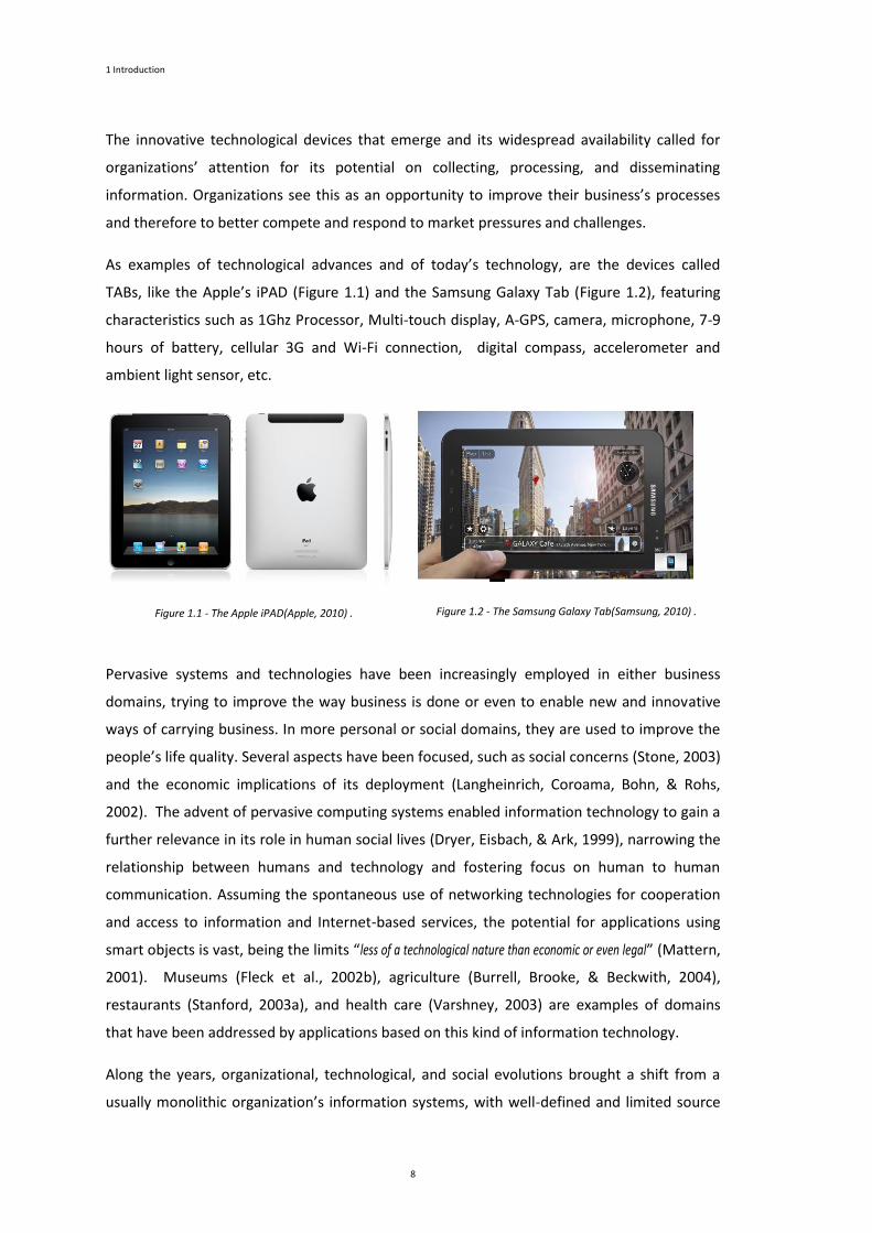
As examples of technological advances and of today’s technology, are the devices called
TABs, like the Apple’s iPAD (Figure 1.1) and the Samsung Galaxy Tab (Figure 1.2), featuring
characteristics such as 1Ghz Processor, Multi-touch display, A-GPS, camera, microphone, 7-9
hours of battery, cellular 3G and Wi-Fi connection, digital compass, accelerometer and
ambient light sensor, etc.
Figure 1.1 - The Apple iPAD(Apple, 2010) .
Figure 1.2 - The Samsung Galaxy Tab(Samsung, 2010) .
Pervasive systems and technologies have been increasingly employed in either business
domains, trying to improve the way business is done or even to enable new and innovative
ways of carrying business. In more personal or social domains, they are used to improve the
people’s life quality. Several aspects have been focused, such as social concerns (Stone, 2003)
and the economic implications of its deployment (Langheinrich, Coroama, Bohn, & Rohs,
2002). The advent of pervasive computing systems enabled information technology to gain a
further relevance in its role in human social lives (Dryer, Eisbach, & Ark, 1999), narrowing the
relationship between humans and technology and fostering focus on human to human
communication. Assuming the spontaneous use of networking technologies for cooperation
and access to information and Internet-based services, the potential for applications using
smart objects is vast, being the limits “less of a technological nature than economic or even legal” (Mattern,
2001). Museums (Fleck et al., 2002b), agriculture (Burrell, Brooke, & Beckwith, 2004),
restaurants (Stanford, 2003a), and health care (Varshney, 2003) are examples of domains
that have been addressed by applications based on this kind of information technology.
Along the years, organizational, technological, and social evolutions brought a shift from a
usually monolithic organization’s information systems, with well-defined and limited source

1.1 Pervasive systems
9
inputs, into complex, distributed, and technologically heterogeneous information systems. As
consequence, an increasing demand occurs for software development in order to realize
intended applications for these pervasive information systems, taking advantage of those
technologies.
1.2 Methodological Challenges
Focus on models in the development of software systems is not a recent issue. In the history
of software development, emphasis on models has begun some years ago, particularly when
software systems became so complex and big to deal. They were difficult to build and
frequently many projects were unsuccessful. In consequence, structured approaches
(function-oriented methods, object-oriented methods) to software development appeared to
facilitate the production of high-quality and cost-effective systems, such as, for example, the
Yourdon System Method (Yourdon, 1983) that, beyond establishing well-defined steps and
activities of the development process, focused on models to help to abstract, analyse and
design software systems.
Interest and focus on models arise again today with a further emphasis due to recent
developments that resulted on the establishment of important widely known and accepted
standards. Particularly, among these, are those originated from the Object Management
Group (OMG) (such as the Unified Modelling Language (UML), which unifies modelling
languages, and the published OMG´s initiative Model-Driven Architecture (MDA), which
stands for new guidelines to the architecture and development of software systems). These
standards (and as well as others) represent, through common agreement and acceptance,
what the best the community has reached in terms of practices, and set up the basis for
further innovations or developments. These standards also enable reuse of knowledge and
artefacts, tools specialization and interoperation, providing thus a “significant impetus for further
progress” (Selic, 2003b). Another key enabler of the movement on focusing in models in
software development is the availability of more powerful Computer-Aided Software
Engineering (CASE) tools supporting the development and management of models and the
generation of code.
For some, model-driven development (MDD) is considered “the first true generational shift in
programming technology since the introduction of compilers” (Selic, 2003b), and it can profoundly change
the way applications are developed (Atkinson & Kuhne, 2003). Automating many of the
complex and routine programming tasks, MDD allows developers to be able to focus on the

1 Introduction
10
functionality that the system needs to deliver and on its general architecture, instead of
worrying about every technical details inherent to the use of a programming language
(Atkinson & Kuhne, 2003).
Developing software solutions is not easy. Brown (Brown, 2004) considers that the following
difficulties arise in the development of software solutions: (i) understand highly complex
business domains and management of the huge development effort; (ii) time-to-market
pressures; (iii) complexity of target software platforms, involving not only new hot
technologies, as also a diverse and complex assortment of legacy technology infrastructure,
frequently kept with poor documentation.
The effective development of today’s application requires that there must be a continuous
effort on the research of better approaches, languages, techniques and tools for the software
development that enables one to face the continuous increasing of complexity of the
development of software solutions. Today, when building large software systems, the main
challenge for software developers is to “handle complexity and to adapt quickly to changes” (Schmoelzer
et al., 2004). Model-driven approaches can be a response to this challenge, as they have the
objective to “increase productivity and reduce time-to-market”, which is attained by a using development
concepts closer to the problem domain than “those offered by programming languages” (Sendall &
Kozaczynski, 2003).
The adoption of a MDD approach to software development for PIS has to consider what MDD
has to offer and which characteristics of pervasive information systems become relevant to
software development. By this way, it will be possible to provide higher effectiveness on
development and evolution of PIS. When intending to develop software for PIS, relevant
characteristics of those are the elevated number of devices that can be involved, the pace of
technological innovations, the heterogeneity of the devices, and potential complexity of
interactions that may exist.
In this document, unless otherwise noticed, the term “model-based/driven” is sometimes
interchangeably used with the term “model-driven development (MDD)” (spite of strictly
having slight but semantic differences).
1.3 Goals and Research Strategy
This thesis aims to contribute for the appropriate use of model-based/driven development
approaches to software development for pervasive information systems (PIS).

1.3 Goals and Research Strategy
11
The goals of this thesis are:
To represent, in a suitable form, the structure and the elements of a project in order
to proceed with an analysis about their suitability for PIS and their model-
based/driven characteristics.
To identify issues in a project that hamper or difficult the suitability of the adopted
approach to cope with pervasive systems (in particular issues related with
heterogeneity), and to support model-based/driven perspectives.
To develop a framework, a strategy, or orientations to facilitate the analysis of
existing projects.
This work considers a case study research strategy. It analyses two projects, both different in
scope and dimension. This strategy treats each of the projects as a separate study, which
facilitates the analysis and “(…) the findings likely to be more robust than having only a single case” (Yin,
2003).
The projects allow showing that the structure and the quality of project elements need
particular attention on their definition in order achieve a proper suitability of the project to
deal with system pervasiveness and to accommodate model-driven/based approaches.
According to Yin (Yin, 2003), five components of a research are important: (i) the research
questions; (ii) the study propositions; (iii) the unit of analysis; (iv) the logic linking the data to
the propositions; (iv) the criteria for interpreting the findings. Next paragraphs instantiate
these components for this study.
Research questions
The research questions are of major importance, as stated by Yin “Defining the research questions is
probably the most important step to be taken in a research study,(…)”(Yin, 2003). The analysis of the projects
aims to provide understanding on answers to the following research questions:
How did a particular project deal with pervasive system’s characteristics?
How did a particular project structure the development process in order to become
suitable for the adoption of a model-based/driven development approach?
How could a particular project improve its development process in order to better
cope with pervasive information systems issues and to easier accommodate a model-
based/driven approach?
1 Introduction
12
Proposition
Regarding this component Yin states “(…) each proposition directs attention to something that should be
examined within the scope of study” (Yin, 2003).
As proposition, it is considered that structure and element definitions of the project are of
crucial importance to the capability of the project to deal with pervasiveness of systems.
Among these elements, modelling artefacts and model transformations have a special
interest as they have major influence on the suitability of accommodation of model-
based/driven approaches. Revealing the structure, the modelling artefacts, model
transformations, allow analysing the pervasiveness capability and the model-based/driven
capability.
Unit of analysis
This component is related as “the fundamental problem of defining what the "case" is (…)” (Yin, 2003). The
project is the main unit of analysis.
Linking data to propositions and criteria for interpreting results
Regarding these last two components, linking the data to propositions and the criteria for
interpreting the findings, Yin further states “The fourth and fifth components have been the least well
developed in case studies” (Yin, 2003).
As Yin stated “Analysing case study evidence is especially difficult because the strategies and techniques have not been
well defined. (…) The analysis of case study evidence is one of the least developed and most difficult aspects of doing case
studies ”(Yin, 2003). As general strategy, it was followed the theoretical propositions of the case
study. More specifically, as this study consists of two projects, a cross-case synthesis is
performed to achieve consolidated findings.
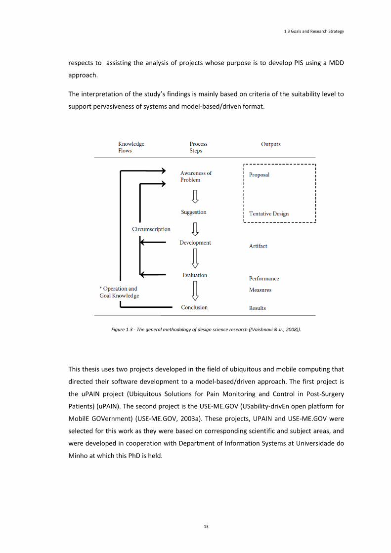
Additionally, to assist the linking of the information gathered from the projects to the
theoretical proposition (related to the importance of the structure and elements of the
development process), SPEM 2.0 specification is used, a development framework is
conceived, the SPEM 2.0 Base Plug-In is extended, and a corresponding pattern is designed
and applied. These particular conceptions and structures (may be seen as design, which may
be uncommon in common case studies) can be nearly framed in the context of the Design
Science Research approach (Vaishnavi & Jr., 2008) and its general methodology (Figure 1.3).
In this context, these conceptions and structures may be seen as a contribution in what
1.3 Goals and Research Strategy
13
respects to assisting the analysis of projects whose purpose is to develop PIS using a MDD
approach.
The interpretation of the study’s findings is mainly based on criteria of the suitability level to
support pervasiveness of systems and model-based/driven format.
Figure 1.3 - The general methodology of design science research ((Vaishnavi & Jr., 2008)).
This thesis uses two projects developed in the field of ubiquitous and mobile computing that
directed their software development to a model-based/driven approach. The first project is
the uPAIN project (Ubiquitous Solutions for Pain Monitoring and Control in Post-Surgery
Patients) (uPAIN). The second project is the USE-ME.GOV (USability-drivEn open platform for
MobilE GOVernment) (USE-ME.GOV, 2003a). These projects, UPAIN and USE-ME.GOV were
selected for this work as they were based on corresponding scientific and subject areas, and
were developed in cooperation with Department of Information Systems at Universidade do
Minho at which this PhD is held.

1 Introduction
14
1.4 Contributions
This thesis contributes with structuring elements and inherent conceptions that allow for
better development of pervasive information systems, enhancing the flexibility to
accommodate heterogeneity of devices, technological innovations, and changes on
functionality requirements. The following paragraphs present the main contributions.
Development Framework. This framework introduces and describes the concepts sustained
on a few perspectives of relevance to the development, called dimensions of development.
Besides the dimensions of development, there are the functional profiles, resources
categories, functional profile instances, global and elementary development process.
SPEM Base 2.0 Plug-In Extension. In consonance with this development framework, the
thesis proposes a SPEM 2.0 Base Plug-In extension to assist in the analysis of the projects. The
SPEM 2.0 Base Plug-In extension defines elements that are fundamental to the definition and
application of a development framework pattern.
Development Framework Pattern. The thesis defines a development framework pattern that
may be applied each of the projects to facilitate the analysis, and also to illustrate how
projects could be improved in order to better cope with the development of PIS and adopting
a model-based/driven approach.
Insight to PIS development using MDD approaches. From the analysis of the projects, the
thesis synthesizes a set of pertinent issues and guidelines related to the adoption of model-
based/driven approaches to pervasive information system development. It shows how the
projects could improve to deal with PIS, using an MDD approach.
1.5 Structure of this Document
This document is structured in seven chapters. Generically, all chapters are preceded by a
chapter cover that exposes a table of contents aiming to facilitate immediate perception and
access of the main headlines of the chapter. Following that chapter cover, a brief summary of
the chapter is presented, aiming to briefly synthesize the main chapter content. The several
sections of the chapter come after the summary, starting with a section of introduction and
ending with a section of conclusion; between those, come the sections pertinent to that
chapter thematic.

1.5 Structure of this Document
15
The seven chapters of this document and their main content are:
Chapter 1: Introduction. This chapter introduces the areas of research, the goals and
research strategy, contribution, and document structure. The areas of research are the
pervasive/ubiquitous computing and model-driven development.
Chapter 2: Pervasive Computing. This chapter introduces the origins, characteristics,
research, business opportunities, and social concerns of pervasive/ubiquitous computing, and
ends presenting the concept of pervasive information systems (PIS).
Chapter 3: Model-Driven Development. This chapter presents Model-Driven Development
(MDD), an approach to software design and development that strongly focuses and relies on
models. Interest and focus on models arise again today with a further emphasis due to
developments that resulted on the establishment of important, widely known, and accepted
standards. This chapter also presents the Model Driven Initiative (MDA) from Object
Management Group (OMG), which fostered the research and establishment of software
development practices based on models. It concludes with considerations about research
efforts needed for effective model-driven development practice.
Chapter 4: Presentation of the Projects. This chapter presents the two projects that this
thesis uses to help to identify issues pertaining to software development for pervasive
information systems. The projects, their common characteristics, issues, and challenges
pertaining to software development of PIS are presented.
Chapter 5: Approach to PIS Development. This chapter presents conceptual structures to
assist the analysis of existing development projects or to the elaboration of new ones. It
presents the Development Framework, the SPEM 2.0 Base Plug-In extension, Framing
Structure, and the Development Framework Pattern.
Chapter 6: Analysis of the Projects. This chapter revisits the projects in order to proceed to
analyse the projects resorting to SPEM 2.0 and to the conceptions and structures, presented
in chapter 5.
Chapter 7: Conclusion. This chapter presents the conclusions about the work performed. It
presents guidelines for future work and research in order to expand and solidify knowledge
about model driven development for pervasive information systems.


Chapter 2
Pervasive Computing
Chapter Contents
2 Pervasive Computing ............................................................................................................................. 19
2.1 Introduction .................................................................................................................................... 19
2.2 A New Computing Paradigm ........................................................................................................... 21
2.3 Business Opportunities and Social Concerns .................................................................................. 27
2.4 Pervasive Information Systems ....................................................................................................... 38
2.5 Conclusion ....................................................................................................................................... 42

18

19
2
Pervasive Computing
This chapter introduces pervasive/ubiquitous computing, a new paradigm for
computing, presents its main characteristics and discusses some terminology. This
new computing paradigm, while bringing some novel applications and business
opportunities, also introduces some social concerns related to security and privacy.
Also included in this chapter is the notion of Pervasive Information System (PIS). PIS
results from the widespread adoption of new pervasive computing technologies into
systems. Such leads to the need of pervasive information systems to cope with
permanent technological evolutions and innovations and changes of requirements,
which have strong impact on software development demands.
2.1 Introduction
Considered a major evolutionary step in computing (Saha & Mukherjee, 2003;
Satyanarayanan, 2001) since introduction the of the Personal Computer, ubiquitous
computing is closely related to (and is an evolution step of ) distributed computing and
mobile computing fields that already identified and studied several technical issues related
with pervasive computing (Satyanarayanan, 2001).
Ubiquitous computing is not the same as mobile computing. Satyanarayanan
(Satyanarayanan, 2001), illustrating the taxonomy of computer systems research problems in
pervasive computing, identifies several research issues that make distinction of pervasive
computing field from that of mobile computing. Pervasive computing includes research issues
as effective use of smart spaces (spaces enriched with embedded computing), invisibility (the

2 Pervasive Computing
20
removal of computing technology from user’s consciousness), localized scalability (the
reducing of interactions from distant entities), and masking uneven conditioning (the smart
environments will be significantly different from each other, but operation must be
continuously provided).
Satyanarayanan (Satyanarayanan, 2001) characterizes pervasive (ubiquitous) computing as
an evolutionary step following two earlier steps of distributed computing and mobile
computing. He stated the research agenda (see Figure 2.1) as involving not only issues related
with environments saturated with computing and communication capabilities and its
“gracefully” interaction with users, but also related with support for mobility of users.
Figure 2.1 – Research agenda for pervasive computing (adapted from (Satyanarayanan, 2001)).
Ubiquitous computing embodies a philosophy different of that inherent to the personal
computers of the 70s. In essence, it aims for computing technology to be not the focus of
attention of the user activity. It even does not require the need of carrying around any
personal computer or PDA to access information; in this world, fully of connected devices,
information will be available and accessible everywhere (Weiser, 1993a). The data, once
entered in a computing system, will be readily available whenever and wherever needed (Ark
& Selker, 1999), being accessible in an intuitive way through the use of devices eventually
different from that one through which the data was entered.
Decreasing emphasis of focus on the personal computer has already occurred with the
emergence of the World Wide Web. For many users the computer is just a machine that
provides a portal to the digital world where they have presence through their homepage,
their email, or chat. In this way, computers are ‘disappearing’ and the focus goes beyond
them (Davies & Gellersen, 2002). Ubiquitous computing brings then “the end of dominance of the
traditional computing” (Ark & Selker, 1999), being computing embedded in more things than just
our personal computer.

2.2 A New Computing Paradigm
21
2.2 A New Computing Paradigm
As Davies and Gellersen (Davies & Gellersen, 2002) noticed, since the initial work of Mark
Weiser, there have been significant developments that improve our ability to deploy
pervasive computing systems. Developments have been technological (improvements in
processing power, storage, communications, miniaturization and portability, or in other IT
technologies such as Global Positioning System (GPS), smart cards, or radio frequency
identification tags). Developments have also been social (there is an increasing acceptance of
introduction of IT technological systems to improve the quality of business process or
people’s security or life).
Beyond the traditional media, the Web has emerged as a new fundamental and valuable
global information system, being widely adopted not only by organizations but also by the
individual. Today, the web is easily accessible in all developed countries, in schools, private
and public organizations, at home, and inside or outside buildings. Also notable has been the
widespread adoption of cellular phones that, along with increasing computing resources,
have acquired improved communication capabilities and new multimedia features. They
allowed a new and quick way to contact and interchange information with people, to access
to the World Wide Web everywhere, and to interconnect computing devices all around the
world (even in the most inhospitable places).
The advent of accessible commercial wireless networks and communications systems further
contributed to dissemination of computing. The embedding of computing devices in objects
or places for monitoring or control, enabled us to envision a “real” physical world enhanced
with information and computing capabilities. These capabilities can be used to facilitate and
pleasure human life in its diverse facets (as the personal or social) or to improve business or
other organizational process. Want, Pering, Borriello and Farkas (Want, et al., 2002) consider
that the “four most notable improvements in hardware technology” during the last decade that directly
affected ubiquitous computing are: wireless networking, processing capability, storage
capability, and high quality displays.
These factors, among others, contributed for a culture characterized not only by having an
easy access to information, but also by demanding for information availability and
consequently; consequently there is an implicit acceptance of surrounding and permanent
computing or other IT devices. Nowadays, there is an increasing feeling that information is
2 Pervasive Computing
22
omnipresent (we just need an IT device to access it) and that computing devices or
applications are naturally part of our daily lives.
Spite all the technological and social developments occurred in last decade, it is argued
(Banavar et al., 2000; Davies & Gellersen, 2002; Saha & Mukherjee, 2003) that many aspects
of Weiser’s vision of ubiquitous computing have not been yet achieved; it has been “more art
than science” (Banavar, et al., 2000). There are some critics about the fact that the devices,
computers, and the environment are seen in a traditional way: the mobile computing devices
are used as “mini-desktops”, and the applications are simply programs (written for those
devices) for which exists a virtual environment provided to perform tasks. Spite of the
existence of critical elements for ubiquitous computing, it is also claimed that, to realize this
vision, it is needed a “seamless integration of component technologies into a system” (Satyanarayanan,
2001).
Pervasive computing has been interpreted, on its maturity evolution, from several different
perspectives that led to different meanings and objectives to different people. In order to
clarify what pervasive computing is about, Banavar (Banavar, et al., 2000) considered that
pervasive computing respects to three things: (i) the way people view and use mobile
computing devices to perform tasks; (ii) the way applications are created and deployed in
support of those tasks; (iii) how the environment is enhanced by the emergence and ubiquity
of new information and functionality. In order to achieve the true benefit and science
perspective of pervasive computing, Banavar states that devices, applications, and
environment need a different thinking. First, a device is “a portal into an application data/space and not a
repository of custom software managed by the user”. Second, an application is “a means by which a user performs a
task, not a piece of software that is written to exploit device’s capabilities”. Third, the computing environment is
“the user’s information enhanced physical surroundings, not a virtual space that exists to store and run software”.
Thinking about ubiquitous computing in this way bears more in mind with Weiser’s vision and
helps to provide a base for reasoning about ubiquitous computing systems, their
characteristics, and to establish research challenges.
Characteristics of ubiquitous computing
Considering the vision about ubiquitous computing, there are key characteristics of
ubiquitous computing systems that differentiate these from traditional computing systems.
Among these are: decentralization (autonomous small devices, taking over specific tasks and
functionality, cooperate and establish a “dynamic network of relationships”), diversification (there is a
move from universal computers to diversified devices for specific purposes), connectivity

2.2 A New Computing Paradigm
23
(different type of devices connect among themselves to exchange data and applications) and
simplicity (pervasive devices, being specialized tools, should be easy and intuitive to use −
“complex technology is hidden behind a friendly user-interface”) (Hansmann, Merck, Nicklous, & Stober,
2003).
In ubiquitous computing, the environment take a relevant place in computing: in “contrast with
most traditional computing, in which the environment is mostly irrelevant, the environment plays a fundamental role for
ubiquitous computing; the environment has influence on the ‘semantics’ of computing” (Ciarletta & Dima, 2000).
There is the need of perceptual information about the environment (Saha & Mukherjee,
2003), location of people and devices. Such information enables for an enhanced interaction
with the users, allowing applications to adapt themselves to their environment, and
constitutes an enabler element for the so-called invisible computing. Several characteristics
about the environment are:
(1) Enhanced physical world. “The nature of the ubiquitous computing implies a physical world enhanced with
mobile or embedded computing devices or other IT kind.” Places and things are enhanced with sensing,
processing, and communication elements (Kindberg & Fox, 2002). “The embedded aspects of pervasive
computing suggest that sensors and actuators will play a significant role in many pervasive applications.” (Ciarletta &
Dima, 2000)
(2) Heterogeneity of devices, systems, and environments. In a ubiquitous computing world,
diversity is a permanent characteristic of the elements that compose ubiquitous computing
systems. There are diverse kinds of systems, computing devices, and other technological
artefacts, varying at a great extend in processing and interaction capabilities. Resulting
essentially from factors as organizational or social needs and limitations, there will be, for a
long period of time, significant variations on the penetration of pervasive computing
technology, resulting in differences on the smartness capabilities of environments
(Satyanarayanan, 2001).
(3) Mobility of users. The mobility of users implies that the surroundings of the users are
always changing with the movement from a ubiquitous environment to another.
Ubiquitous computing is about not only the enhancement of physical world with embedded
computing devices, sensors, actuators, and other elements to provide communications
among these. It also concerns the way computing is disposed in order to interact with users
in support of their activities and goals. As stated by Weiser, “Ubiquitous computing takes place primarily
in the background. (…) the ubiquitous computing leaves you feeling as though you did by yourself” (Weiser, 1993a);
ubiquitous computing is gracefully and seamlessly integrated, allowing for people to not

2 Pervasive Computing
24
(actively) realize that it is there. In this invisible computing, it can be found that: (i) ubiquitous
computing applications “will cohabit with the user’s physical environments, providing unobtrusive support to user’s
tasks, enabling them to focus on their work and to be not obliged to actively initiate active interaction with computers”
(Banavar & Bernstein, 2002); (ii) there will be spontaneous interoperation of software
components in changing environments (Kindberg & Fox, 2002) (the environment contains
infrastructure components and spontaneous components based on the devices that arrive
and leave routinely); (iii) ubiquitous applications are omnipresent either by making
technological devices move with the user or by having applications moving between devices
tracking the user (Banavar & Bernstein, 2002). Thus, ubiquitous computing applications must
be able to adapt to the dynamism of environments, device heterogeneity, resource
constraints, and user’s intent.
Pervasive vs. ubiquitous computing
On its seminal article (Weiser, 1991), Weiser employed the term “ubiquitous” (which refers
to the characteristic of existing or being everywhere at the same time, or being constantly
encountered (Merriam-Webster)) to characterize the writing (an widespread information
technology that can be found everywhere and which presence, not requiring active attention,
conveys information conveyed ready for use). Giving as contrast the presence and need for
attention of the Personal Computer, Weiser envisioned a new way of computers integrate
with people lives: a way in which computers, populating and taking into account the human
environment vanish seamlessly into the background, becoming invisible to people.
On several articles (Weiser, 1993a, 1993b), Weiser reinforced the widespread use of
computing devices and its “invisibility”, allowing for a computing environment where each
person is continuously interacting with hundreds of interconnect computers. Weiser, clearly
stating that computers in the workplace can be as ubiquitous as printed matter, establishes
the goal of ubiquitous computing: “Ubiquitous computing has its goal the non-intrusive availability throughout
the physical environment, virtually, if not effectively, invisible to the user” (Weiser, 1993a). Invisibility is
constantly stressed out (Want, 2000; Weiser, 1994; Weiser, et al., 1999) in this new way of
thinking about computing, which allows for and enhance people to focus on their real tasks
and objectives.
In the same line of thought regarding to writing and electricity (also considered by Weiser as
a technology that with time also became ubiquitous (Weiser & Brown, 1997)), ubiquitous
computing was coined to mean the widespread of computing in the world (in every places
and objects) aiming to support human activities. It exists in the “periphery” (Weiser & Brown,
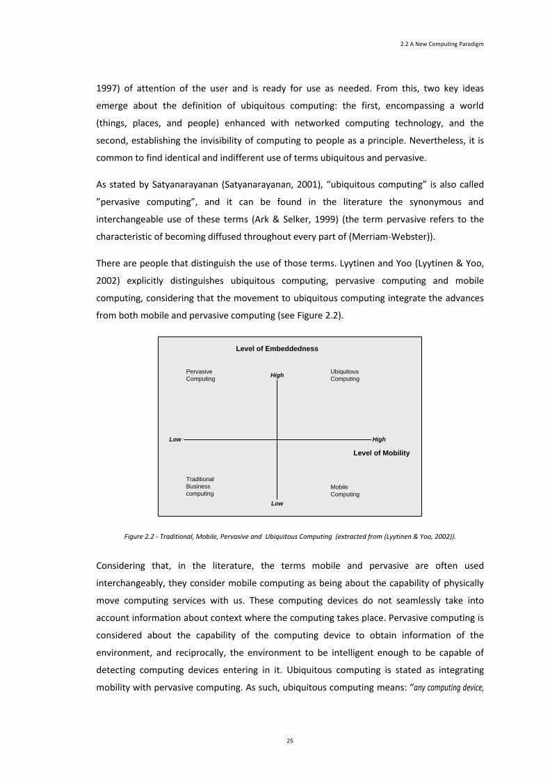
2.2 A New Computing Paradigm
25
1997) of attention of the user and is ready for use as needed. From this, two key ideas
emerge about the definition of ubiquitous computing: the first, encompassing a world
(things, places, and people) enhanced with networked computing technology, and the
second, establishing the invisibility of computing to people as a principle. Nevertheless, it is
common to find identical and indifferent use of terms ubiquitous and pervasive.
As stated by Satyanarayanan (Satyanarayanan, 2001), “ubiquitous computing” is also called
”pervasive computing”, and it can be found in the literature the synonymous and
interchangeable use of these terms (Ark & Selker, 1999) (the term pervasive refers to the
characteristic of becoming diffused throughout every part of (Merriam-Webster)).
There are people that distinguish the use of those terms. Lyytinen and Yoo (Lyytinen & Yoo,
2002) explicitly distinguishes ubiquitous computing, pervasive computing and mobile
computing, considering that the movement to ubiquitous computing integrate the advances
from both mobile and pervasive computing (see Figure 2.2).
Level of Embeddedness
Low High
High
Low
Level of Mobility
Pervasive
Computing
Traditional
Business
computing
Ubiquitous
Computing
Mobile
Computing
Figure 2.2 - Traditional, Mobile, Pervasive and Ubiquitous Computing (extracted from (Lyytinen & Yoo, 2002)).
Considering that, in the literature, the terms mobile and pervasive are often used
interchangeably, they consider mobile computing as being about the capability of physically
move computing services with us. These computing devices do not seamlessly take into
account information about context where the computing takes place. Pervasive computing is
considered about the capability of the computing device to obtain information of the
environment, and reciprocally, the environment to be intelligent enough to be capable of
detecting computing devices entering in it. Ubiquitous computing is stated as integrating
mobility with pervasive computing. As such, ubiquitous computing means: “any computing device,

2 Pervasive Computing
26
while moving with us, can build incrementally dynamic models of its various environments and configure its services
accordingly” (Lyytinen & Yoo, 2002).
Ciarletta and Dima (Ciarletta & Dima, 2000), consider that pervasive computing (resulting
from the convergence of personal computing, embedded systems, and computing
networking) distinguishes itself from computing in general by its emphasis on ubiquity,
interconnection and dynamism. They state that, striving to be low-cost, embedded,
distributed and non-intrusive, “Pervasive computing aspires to be ubiquitous ;(…)”.
Gupta, Wang-Chien Purakayastha, and Srimani (Gupta, Wang-Chien, Purakayastha, & Srimani,
2001) stated that “The word pervasive means having power to spread throughout“. They consider that
pervasive computing, encompass technologies such as mobile and wearable computing, and
is “an environment where people interact with various companion, embedded, or invisible computers(…) this environment is
populated with networked devices aware of their surroundings and able to provide or use services from peers”.
Friedemann Mattern (Mattern, 2001) notices that Weiser saw the term “ubiquitous
computing” in a “more academic and idealistic sense as an unobtrusive, human-centric technology vision“.
Nevertheless, industry has coined the term “pervasive computing” with a slightly different
slant: “Even though its vision is still to integrate information processing almost invisibly into everyday objects, its primary
goal is to use such objects in the near future in the fields of electronic commerce and Web-based business processes”.
Taking into account the aforementioned uses and meanings of the terms “ubiquitous” and
“pervasive”, it becomes clear that is convenient some reflection and clarification about these
terms. With the above considerations in mind, a search on a dictionary (Merriam-Webster)
reveals that the term “ubiquitous” refers to the characteristic of existing or being everywhere
at the same time, of being constantly encountered, while the term “pervasive” refers to the
characteristic of becoming diffused throughout every part of. Therefore, it can be said that
pervasive doesn’t mean to be at several places at the same time and that doesn’t bring the
idea of invisibility, while ubiquitous does implies so through its constant presence (and as
such, being constantly encountered, fading into the background; and that’s the way Weiser
defined it). Pervasive seems to have a stronger connotation with a physical, localized
perspective, where computing technology penetrates things. Ubiquitous is more general,
referring to a computing technology that is found seamlessly everywhere. Something may be
pervasive but not necessarily ubiquitous.
By its definition, the term ubiquitous seems more adequate than pervasive to express Weiser
vision of computing, and Lyytinen and Yoo (Lyytinen & Yoo, 2002) provide a good contribute
to express clearly the distinctions between the two terms. As Ciarletta and Dima (Ciarletta &

2.2 A New Computing Paradigm
27
Dima, 2000) stated, pervasive computing tries and tends to be ubiquitous: always present
everywhere, in the background, integrated seamlessly in an unobtrusive way.
We can talk about embedded, mobile, pervasive, and ubiquitous computing. Through
embedment and mobility, we reach pervasive, and through pervasive we achieve ubiquitous.
Computers and IT devices alike, by themselves, are not ubiquitous; but they collectively
provide support for pervasive systems and ubiquitous computing. Pervasiveness relates with
the degree of penetration and dissemination of computing in our physical environment.
Ubiquitous computing comes indeed as an emergent property of several interconnected
computing (or other IT like) devices (embedded or mobile) pervasively integrated that are
orchestrated in order to provide, in an invisible fashion, an unobtrusive and helpful assistance
to users activities, and thus, enabling ubiquitous computing.
Embedded and mobile devices allow us to compose pervasive systems, which conveniently
orchestrated, can provide users with ubiquitous services/applications. By its strict meaning,
“pervasive computing” does not necessarily imply the defining characteristics of Mark
Weiser’s ubiquitous computing, such as the invisibility and engendering of calmness to the
user. Ubiquitous computing encompasses, from an application perspective, a stronger focus
on the way of interaction, on permanent availability, and on functionality provided by
computing to the user. Table 2.1 reflects the appropriate usage of the terms regarding to
pervasiveness and ubiquity.
Terms Pervasive Ubiquitous Terms Pervasive Ubiquitous
Technology Yes No Applications Yes Yes
Devices Yes No Services Yes Yes
Systems Yes Avoid Computing Yes Yes
Table 2.1 - Appropriate usage of terms pervasive and ubiquitous.
2.3 Business Opportunities and Social Concerns
In order to explore and realize the necessary technology and the envisioned pervasive
systems and technologies, industry and academy took several research initiatives.

2 Pervasive Computing
28
In the development of pervasive technologies and systems, several aspects have been
focused, such as social concerns (Stone, 2003) and the economic and political implications of
its deployment (Langheinrich, et al., 2002). There has been a permanent research and
innovation of pervasive systems in: (i) business domains, which try to improve businesses or
even to enable new and innovative ways of carrying businesses; (ii) in personal or social
domains, which try to improve the people’s life quality. The benefits and applications of
pervasive computing are far from having reached an end. Other business domains, such as
insurance companies or government agencies, can also take benefits of pervasive computing.
What was initially confined in developing technology to make pervasive computing out of a
vision (Lyytinen & Yoo, 2002), surpassed the initial restricted frontiers to reach the
development of applications for organizational domains, enabling for enhancements of
current business processes or even to assist the development of new business models
(Langheinrich, et al., 2002).
Business Concerns
From a business perspective, ubiquitous computing brings the opportunity to introduce
changes in the way business and consumers interact with each other (Fano & Gershman,
2002). It allows for an improvement on mutual intercommunications, richer and innovative
interactions, and closer relationships. People become able to interact with services not only
through telephone or PC but also through products. Fano and Geshman (Fano & Gershman,
2002), through the “Online Medicine Cabinet” (Accenture, 2004d) and the “Mobile Valet”
(Accenture, 2004e) prototypes4, exemplify how ubiquitous computing could transform
customer relationships and services, emphasizing the characteristics of awareness,
accessibility, and responsiveness on relationships, location and service scope, and duration
and frequency of a customer interaction.
Emerging technologies associated with ubiquitous computing enables new kinds of services.
Gershman (Gershman, 2002) states that these new kinds of services will lead to a new era of
ubiquitous commerce. These services will result from three primary capabilities of ubiquitous
computing devices: (i) as service channels, “to provide a service channel for remote service providers (…)”; (ii)
as sensors “to inform these services of local context of the user (…)”; (iii) and as effectors “to enable these
services to affect things in the user environment (…)”.
4 Those, as stated by Fano and Gershman, are prototypes developed at Accenture Technology Labs.

2.3 Business Opportunities and Social Concerns
29
Strassner and Schoch (Strassner & Schoch, 2002) consider that three ubiquitous computing
technologies have a direct and strong impact on business processes: (i) automatic
identification; (ii) localization; (iii) and sensor technology.
Products uniquely identified by invisible tags allow people to carry devices that
instantaneously access additional information about the product, thus merging both physical
and virtual worlds. A personal mobile device with computing capabilities will be, in future, a
common clothing accessory like the wristwatches today and eventually, a usual interface to a
variety of smart objects.
As previously said, enhancement of objects with increasing sensing, computation, and
communication capabilities, allow for richer interactions with people, services, and other
objects. Capable of monitoring of their own critical parameters, products will be able to
communicate, with responsible entities, abnormal or relevant parameters values or events; if
possible, they will take corrective actions (Bohn, Coroamã, Langheinrich, Mattern, & Rohs,
2004) in order to re-establish normality. Smart products will be able to communicate with
their producers until they are sold, or eventually, during all their lifetime. Things that can do
shopping themselves (as photocopiers ordering for paper), furniture that can monitor its
usage (sofas that count the number of persons that sit on it), detailed history of products (as
used cars that can offer a detailed history, of its production, use and repair) are examples of
what is imagined as concrete applications of ubiquitous computing. As entities in the
economic processes improve their capabilities on monitoring, gathering, retrieving, and
processing information, it will ultimately become possible in real-time to witness and (in
some extent) to control the lifecycle of products (from their manufacturing to their complete
consumption) (Bohn, et al., 2004) .
Business benefits and ubiquitous computing technologies have a mutual influence in each
other: ubiquitous computing technologies are seen has offering support for potential
business benefits to organization efficiency, and those potential benefits constitute a driving
force and key factors to further research and deployment of ubiquitous computing
technologies (Bohn, et al., 2004); this leads to a permanent, vigorous, and rapid proliferation
of information technology.
Aware of those business benefits potentially offered by ubiquitous computing technologies,
the industry has set their attention on the deployment of those technologies in supporting
applications in diverse domains, pursuing imagined business benefits. Government agencies,
insurance companies, organizations of several domains have been developing projects aiming
to collect the potential gains of deployment of ubiquitous computing. Marketing, inventory

2 Pervasive Computing
30
management, pay-per-use are examples of intervention areas. Museums (Fleck et al., 2002a),
agriculture (Burrell, et al., 2004), restaurants (Stanford, 2003b), and health care (Varshney,
2003) are examples of business domains that have been addressed by applications based on
this kind of information technology. For example, in elder care (Stanford, 2002), systems have
been deployed to improve the quality and the efficiency of care delivery to the elderly. This
improvement came through the assistance to the staff in identifying people needing
immediate attention and in monitoring trends, which resulted in an enhanced service and an
enriched environment.
As example of research and deployment of ubiquitous computing systems at Accenture
Technology Labs (Accenture, 2004f), ubiquitous computing research initiatives resulted in
projects that exemplify new applications with ubiquitous computing technologies (some of
them envisioned to enhance business performance). Among such project examples are:
(1) Networked automation (Accenture, 2004c). Demonstrated how innovative technology can
enhance safety on a plant floor through automated machines that use technologies such as
sensors and radio frequency identification (RFID) tags, as well as ad hoc network
communication devices to provide information reporting capabilities, and to control objects.
(2) Freight tracking (Accenture, 2004a). Improves the efficiency of cargo management “(…) by
allowing rail companies, railroad yards and large suppliers with separate rail facilities to better control and monitor their
freight movements. The prototype makes train wagons "intelligent" and allows them to assume inventory management
responsibilities by reporting their exact location and sequence within a line of cars.”
(3)Virtual Home Improvement Services (Accenture, 2004g). Focus on assistance in situations
where expert helped is needed at point of need such as “machine repair, travel, cooking, shopping, fitness
training, gardening, first aid and personal security”, using web services.
(4) Manufacturing services (Accenture, 2004b). Manufacturing Services prototype show
“(…)how the combination of embedded computing, sensors, and short-range wireless technologies makes for an “aware”
environment. Such environments create intelligent pieces of equipment that are aware of their status and surroundings,
interact with technicians, revolutionize how services are performed and automate the regulatory (or even tax) compliance
process.”
(5) Physical media tracking (Accenture, 2004d). Help to reduce the potential for theft and
human error “(…) all while streamlining the entire inventory management process. (…) the prototype makes products
“intelligent” and allows them to assume inventory management responsibilities by continuously reporting their exact
locations, wherever they may be in the value chain.”

2.3 Business Opportunities and Social Concerns
31
(6) Real-world Showroom (Accenture, 2004e). Application prototype enabling people to find
information about products “(…) as they encounter them in their daily lives. If they wish, they can buy the item on
the spot. With Real-World Showroom, commerce and interaction can take place wherever and whenever people see and use
products, not in the store or on a website.”
(7) Mobile Valet (Accenture, 2004e). A palmtop computer demonstrates how to use mobile
devices as a service channel. It “capitalizes on the ubiquity of sensors, tags, speakers and video screens which we
encounter everywhere, making it possible to deliver a whole range of services—and in much greater detail and resolution
than just though a mobile phone! ”. “Demonstrates how innovative services may be delivered to help people do what they
are doing, wherever they happen to be.”
(8) Online Medicine Cabinet (Accenture, 2004d). Shows how technology helps in our
healthcare; “It combines sensors with the power of the Internet and embedded computers to create a "situated portal"—
a smart appliance that continuously monitors the needs of people and responds with appropriate, individualized services.”
A world fully interconnected with smart devices, tagging technologies, and aware personal
mobile computing devices, along with widespread networking communications
infrastructures, will lead to change of perception of our surroundings. Such change of
surroundings perception (with new or improved ways of interaction among people, business
or objects) will trigger social and economic changes, which will ultimately be of political
relevance (Mattern, 2001). As Fano and Gershman (Fano & Gershman, 2002) says, “ubiquitous
computing will change the way we live with technology”.
Social Concerns
Computing technology developments in last decade enabled information to migrate from
paper to digital format, enabling it to be easily stored, reproduced, and published.
Networking technologies developments allowed easier and faster communications and the
ability of to provide of new networked-based services.
Development in storage database technology unconstrained the amount of information that
could be stored. Searching technologies jointly with analysis tools, allowed for this
information be accurate and to be timely accessed and used.
Development on input modalities beyond the traditional mouse and keyboard, on digital
photography and video, and on sensing technologies, allowed for a broader forms and kinds
of information to be digitally gathered and managed. Internet technologies and applications,
such as the Web and electronic mail, offering a privileged means of efficient communication

2 Pervasive Computing
32
among people and organizations, fostered the acceptance and introduction of digital
information and processing on personal, social, and business life. Beyond laptops computers,
personal digital assistants (PDAs) and smart phones came to light to offer an always present
personal mobile computing, frequently with data wireless networking and voice
communication. Beyond general computing and communication, those devices allowed us to
deal with an increasingly number of available computing enhanced artefacts.
Technology assisted us in digitalizing not only all the information and the processes that deal
with that information, but also our presence and the presence of objects surrounding us.
Context-aware systems and monitoring systems also became common in order to provide for
easy systems interaction, improvement of efficiency or security. As Ark and Selker say (Ark &
Selker, 1999), “we should not have to carry around devices containing our information. Rather, devices will recognize
who we are and obtain information about us, through ‘remembrance agents’ or adaptive user models, Internet information
storage, or other means.”
Ubiquitous computing promises further technology penetration on human lives, through
computing and network augmentation of the environment, enabling the merging of the
physical and virtual worlds. Projects such as Cooltown (Barton & Kindberg, 2001; Debaty,
Goddi, & Vorbau, 2005; Kindberg et al., 2000) are examples of research on this worlds
merging. More and more the digital permeate the physical space in a seamless manner and
the computing expected to be everywhere (Ark & Selker, 1999). The advent of ubiquitous
computing systems enabled information technology to gain a further relevance in its role in
human social lives (Dryer, et al., 1999), narrowing the relationship between humans and
technology and fostering focus on human to human communication.
As the field of ubiquitous computing matures, key issues start shifting away from technical
issues to more business and social domains (Langheinrich, et al., 2002). If assisting human life
with computing capabilities seems commonly accepted as a good intention, the way to
realize such remains unclear and generally not well agreed or comprehended.
Computerizing our activities or personal information and, in particular, keeping digital track
of part of those, while seen by some justified as personal, business, social convenience or
necessity (e.g., for security), has also been seen by others as a potential risk for person
privacy (and eventually security). Ubiquitous computing with its pervasiveness and sensing
capabilities, along with its invisibleness, bring novel possibilities; for some people they are
motive of contentment and for others they are motive of increased concerns.

2.3 Business Opportunities and Social Concerns
33
Envisioning that this “embodied virtuality” would make “individuals more aware of other people on the
ends of their computer links” (Weiser, 1991), Weiser early noticed that ubiquitous computing have
impact on the relationships of people and technology (Weiser, et al., 1999).
Changing the focus of attention away from computers themselves to activities, ubiquitous
computing could enhance human relationships, work practices, and knowledge sharing.
Nonetheless, as he stated then, ubiquitous computing research also brought attention to
other issues, such as its capabilities of monitoring and control, and privacy: “If the computational
system is invisible as well as extensive, it becomes hard to know what is controlling what, what is connected to what, where
information is flowing, how it is being used, what is broken (vs what is working correctly, but not helpfully), and what are the
consequences of any given action (including simply walking into a room).” (Weiser, et al., 1999).
With its sensing capabilities, ubiquitous computing has impact on the social environments
where it is introduced (Banavar & Bernstein, 2002). Personal privacy will be affected since
broadly accessible, available, and effective small sensors and processors “allow for a much more
comprehensive automated surveillance of the environment, including what we do and say” (Mattern, 2001); and if
Internet is extended into everyday objects, this will result in “enormous challenges for privacy”
(Mattern, 2001).
Several positions of concern about ubiquitous computing have been related (Stone, 2003),
being privacy and liberty issues one of the most focused. Others concerns include worries
about building of an infrastructure that will enable for totalitarian control, and the
transformations that this technology can bring to human existence (such as things getting too
easier to be done, or the augmentation of human body capabilities (Stone, 2003) beyond
reasonable common sense). Given the biotechnology and nanotechnology developments,
almost anything can be expected.
Technology developments and its widespread adoption leads to fear that as more as life
becomes “technological”, it can also become less “human” (Dryer, et al., 1999). Brief
accounts of criticism to the ambition of the ubiquity of computing are given in (Bohn, et al.,
2004).
As an example of technology that raised concerns related to its adoption, is the VeriChip
(Stone, 2003). The VeriChip (VeriChip, 2006b) is a miniaturized Radio Frequency Identification
(RFID) device implanted under the skin of human body. “About the size of a grain of rice” (VeriChip,
2006b), it contains a individual unique verification number, which is transmitted by the chip
when a scanner energizes it. This unique identification number can be used to identify
uniquely an individual. Among the potential domains of application of this technology, is the

2 Pervasive Computing
34
security domain, such as access control to facilities and equipment, and transactions
requiring robust or immediate identification (VeriChip, 2006c).
Figure 2.3- The VeriChip (extracted from (Verichip, 2006a)).
Privacy has been, for decades, concern to people. The advent of modern photography, the
printing press, the automated data processing, credit cards, and the Internet have sparked
attention to privacy. Privacy concerns took different focuses accordingly to technological
developments, being recognized some forms of privacy: media privacy, territorial privacy,
communication privacy, bodily privacy and information privacy (mentions of these forms of
privacy − with exception to the media privacy − can also be found in (Beresford & Stajano,
2003)). This last form of privacy – information privacy – is the one that these days most
promote concerns (Langheinrich, 2001) (location privacy is considered a particular type of
information privacy, and is defined as “the ability to prevent other parties from learning one’s current or past
location” (Beresford & Stajano, 2003)).
Issues related with the adequate collection, use, and dissemination of information have been
for long time subject to considerations in human communication (Abowd & Mynatt, 2000),
resulting on several legislations and recommendations5, such as: (i) the United States (US)
Privacy Act of 1974, in which principles of fair information practices are established
(openness and transparency, individual participation, collection limitation, data quality, use
limitation, reasonable security and accountability); (ii) and the European Union (EU) Directive
95/46/EC of 1995, which beyond the limitation of data transfers to non-EU countries, add the
notion of explicit consent to the fair information practices, are two examples of privacy
legislation (Langheinrich, 2001). Organization for Economic Co-operation and Development
(OECD) Guidelines (OECD, 1980) and Safe Harbor framework (USDoC, 2000) – an U.S.
Department of Commerce in consultation with the European Commission effort – are other
initiatives on privacy legislation domain. The former, aimed to help harmonising national
privacy legislation and, at the same time, to prevent interruptions in international flows of
5 Other general previous legislation or recommendations on privacy in general, such as the England’s 1361 Justices of the Peace Act, The Fourth Amendment to the US Constitution, the 1890 US Supreme Cout Justice Louis Brandeis and the 1948 Universal Declaration of Human Rights) can also be found referenced in (Beresford & Stajano, 2003).

2.3 Business Opportunities and Social Concerns
35
data OECD Member countries. The latter, to bridge the different privacy approaches between
European Union and United States.
As reported by Langheinrich (Langheinrich, 2001), there is also criticism about the
enforcement of privacy. Focusing on issues of feasibility, convenience, communitarian, and
egalitarian, they argue that, often, life is better without privacy. Different motivations for
protection of privacy in laws and standards (Lessig, 1999) have been noticed6 (Bohn, et al.,
2004; Langheinrich, et al., 2002). These are: privacy as empowerment (“to give people the right to
control the publication and distribution of information about themselves”), as utility (“providing protection against
nuisances such as unsolicited phone calls or emails”), as dignity (entails “being free from unsubstantiated suspicion”
and “equilibrium of information available between to people”), and as constraint of power/regulating agent
(“a tool for keeping checks and balances on a ruling elite’s power”).
Besides the considerations reported by Weiser (Weiser, et al., 1999), the literature is fertile
on appreciations about information privacy related to ubiquitous computing (e.g., (Abowd &
Mynatt, 2000; Beckwith, 2003; Beresford & Stajano, 2003; Jiang & Landay, 2002;
Langheinrich, 2001; Mattern, 2001; Want, Hopper, Falcão, & Gibbons, 1992)).
Ubiquitous computing is generally considered has having impact on privacy, as it extends
monitoring capabilities in both spatial scope and temporal coverage (as since from the pre-
natal diagnoses, through birth and growth to the oldness of people) (Bohn, et al., 2004). It
may create new opportunities of outrage of privacy – or, as Gary Marx argued, the “border
crossings”. Gary Marx (Marx, 2001) in its work about public and private (and referenced in
(Bohn, et al., 2004; Jiang & Landay, 2002; Langheinrich, et al., 2002)), states that, with respect
to surveillance, “central to the acceptance or sense of outrage (…) are the implications for crossing personal borders”.
He argues that, when violation of personal borders occurs, it involves the breach of one or
more the borders. These borders are the natural border (what naturally achieve by our
senses), social border (expectations of confidentiality in certain social groups), spatial or
temporal border (expectation that part of lives can exist in isolation from others parts), and
border due to ephemeral and transitory effects (related to spontaneous utterance or action
expected to be rapidly forgot).
Among these borders, the one that might be easier to satisfy in the design of ubiquitous
computing systems is the natural border. The occurrence extent of border crossings will
depend on a large extent of the searching capabilities of the ubiquitous computing systems;
the monitoring and search capabilities of ubiquitous computing systems “will very likely provide
6 These motivations reported were distinguished by Lawrence Lessig, as noticed by Langheirich and by Bohn.
2 Pervasive Computing
36
their developers, owners, and regulators with a significant tool for driving the future development of privacy concepts within
society” (Bohn, et al., 2004)
Beckwith, to analyse risks on his work “Design for Ubiquity: the perception of privacy”
(Beckwith, 2003), considers three aspects of personal information ( borrowed from a model
of Adams (Anne, 1999)) that determine people’s reasoning about privacy. These aspects are:
(i) information receiver (who will use it); (ii) information usage (how will it be used –data can
be collected from various sources (such as sensors) and combined to derive secondary data,
which may lead to problems as there may be various not imagined uses for data fused); (iii)
information sensitivity (how sensitive it is). The interplay of these aspects is considered as
determining how privacy and potential violations are perceived by people (Beckwith, 2003).
Some insight into and a basis for assessment of issues pertaining the judging of privacy and
the implication of pervasive technologies are exposed, through a proposed framework, by
Jacobs and Abowd (Jacobs & Abowd, 2003) in order to help ubiquitous computing systems
designers to better assess the implications of systems designs into privacy concerns.
Given the general concerns, it seems necessary some attention to the design of ubiquitous
computing systems. Some suggestions to the design of these systems are made. First, the
sparse use of sensing technologies and careful attention to border crossings (communication
concepts evaluated according to existent social borders; questioning of searching capabilities
that allows spatial and temporal border crossings; introduction of the concept of ephemeral,
transitory effects in the architecture, allowing for example that information slowly decays
over time) (Langheinrich, et al., 2002). Second, to restrict data usage and to keep the
potential consumers low (Beckwith, 2003). The deployment of ubiquitous computing systems
“will in many cases have implications beyond the technical obvious ones” and “designers can greatly benefit
from evaluating the effects of this deployment “using existing concepts in disciplines such as social,
economic, and legal sciences” (Langheinrich, et al., 2002).
At the present, computers are crucial to assistance of everyday life, providing support for
activities or systems related to critical systems and communications. Our dependence on
their correct and reliable functioning keeps growing as more and more these and other
information appliances digitalize our world. And as Bohn (Bohn, et al., 2004) states, if today,
in most cases, “we are still able to decide for ourselves whether we want to use devices equipped with modern computer
technology”, in the future, “it might not be possible to escape from this sort of technologically induced dependence”.
The proliferation of these technologies in our everyday life leads to the need of attention to
less technical and more social aspects of ubiquitous computing systems (Bohn, et al., 2004).
2.3 Business Opportunities and Social Concerns
37
In an environment full of thousands of smart devices dedicated to facilitate and to promote
our activities and well-being, our dependence on ubiquitous computing systems requires us
to demand from them, full reliability of the services offered and their correct behaviour
accordingly to our needs and circumstances. In this perspective, these systems must satisfy
aspects such as: (i) manageability (being able to be easily understood and controlled); (ii)
predictability (relatively easiness of use and expected behaviour − ubiquitous underlying
invisibility makes “fault detection and diagnosis fundamentally difficult”); (iii) dependability (ongoing
support of activities in even is partial failures of individual device or service interruptions −
this may be achieved through “alternative concepts and mechanisms (…) such as explicit diversification of
functions” ) (Bohn, et al., 2004).
As expressed by Bohn (Bohn, et al., 2004), beyond privacy and the afore-mentioned
reliability, there are other issues that must be taken into account. Among these are: (i)
delegation of control - “in order to minimize the need for human intervention, new concepts for delegating control
are necessary”; (ii) content control - who guarantees the information provided by the smart
objects; (iii) system control - will the smart objects or systems always obey to their owner or
will they enforce guidelines of third parties, such as insurances, manufacturers or judicial
power (iv) accountability - with autonomous objects and systems, it is need to clarify who is
responsible for business transactions and for informing users about transactions; (v) social
compatibility - for human participation in highly dynamic systems, “their parameters have to be
adjusted accordingly”; (vi) transparency - in a pay-per-use model full of “short-term contracts and
micropayments”, its necessary to devise how we could acceptably keep track of those; (vii)
knowledge sustainability - in highly dynamic systems, our nowadays information inertia
(validity of information for an extend period of time) tends to diminish, being the
sustainability of knowledge risking to be lost (“an experience that was valid and useful one minute could
become obsolete and unusable the next”), which may in the long term “contribute to an increased uncertainty and
lack of direction for people in society”; (viii) fairness - marketing can provide for tailored offers
accomplishing to eliminate unwanted offers, but there is a need attention to situations on
which information is withheld from consumer because he is not worth for the offer (in
opposite to the offer not being worth to the consumer), which may lead to reinforced
injustices; (ix) acceptance - “beyond any perceived sinister motives (…), a widespread public acceptance of
ubiquitous computing also rests on issues of an almost philosophical nature (…)”; (x) feasibility and credibility - in
order to not reduce acceptability of ubiquitous computing technologies, ubiquitous
computing must effectively bring benefits to the stressed and hurry life of people and not
stay for improved efficiency of them; (xi) artefact autonomy − networked and interaction
dependent objects (integrated in an environment) may be seem as being less autonomous

2 Pervasive Computing
38
and inherently more error-prone; (xii) impact on health and on environment − a world fully of
countless computing devices or information appliances raises concerns about the
environment, which are related to “raw material consumption, energy consumption, and disposal” (the
electromagnetic radiation resulting from the widespread availability of wireless
communications also leads to worries about its possible and extend of negative effects on the
human body); (xiii) relationship between man and the world − from a philosophical point of
view, the augmentation of the environment can be seen as doing changes on it in a way that
it will let off being the “environment”, the “natural world”, but a mere artefact of our
extensions, losing fundamental properties.
Questions are opened and they evolve along with new possibilities of interactions, services,
and its integration as systems in our everyday lives. This results on the emergence of new or
further advanced ubiquitous computing technologies.
The concerns expressed and the expected vision’s benefits will remain as topics of debate
and analysis on the community. Notwithstanding, it is a certainty that ubiquitous
technologies will be increasingly integrated on everyday life and, simultaneously beyond of
research, focus of attention of business, social, political and legal domains.
2.4 Pervasive Information Systems
Business competition among organizations requires that an organization, in order to be
successful, opportunely meets market demand with the best suitable and competitive supply
at minimal cost. Among others requirements, adequateness of business processes and their
efficient implementation, constitute central issues to the organizations’ ability to be
competitive and successful. Information and knowledge are (beyond land and natural
resources, human labour, and financial capital) fundamental resources of an organization
(Sage & Rouse, 1999). Information can be used not only as a resource to the production of
goods or services, but also as an asset inherent to the organization structure, or even, as a
product to be commercialized (Gordon & Gordon, 2004a). In this context, information,
information technologies, information systems, and information management play a crucial
role.
Widespread availability of affordable and innovative information technologies promoted the
attention individuals and organizations to the efficiency and effectiveness of information
management regarding to the way they acquire, process, store, retrieve, communicate, use,
and share information (Gordon & Gordon, 2004a). In order to take full benefits of the

2.4 Pervasive Information Systems
39
opportunities offered by information technologies, these need to be “appropriately integrated
within organizational frameworks” (Sage & Rouse, 1999), and hence, they will not only provide a solid
basis to sustain the needed information and to achieve effectiveness at both individual and
organizational levels, but also to leverage the investment on these information technologies.
To deal with market pressures and competition, organizations must also to possess the
capability to establish rapidly new or to change existing business requirements or processes.
Such necessity, in conjunction with a reality of permanent technological innovations and
developments, requires that organization’s supporting information systems and inherent
subsystems be conceived to deal with change and evolution with minimal business
disturbance and reduced costs.
Information systems (IS), known as systems that “collect, process, store, analyse, and disseminate
information for a specific purpose” (Turban, McLean, & Wetherbe, 2001), are planned, designed and
deployed in an organization with the purpose to support its business operations, to assist its
management activities, or to produce business’s valuable information assets or products. It is
through the proper project and design of those information systems that it will be possible to
satisfy efficiently the organizational or personal information needs in the pursuit of defined
goals. Additionally, the correct definition and design of information systems are important to
everybody’s satisfaction regarding to information security and privacy, and other social
concerns, thus assuring a higher degree of reliance on the system deployed.
Within an organization, and mainly from a management perspective, information systems
were classified in several ways:
(1) Gordon et al. (Gordon & Gordon, 2004a, 2004b) classify information systems according to
two dimensions: their purpose and their scope. In the purpose dimension, several types of
information systems are the automation systems, transaction-processing systems,
management information systems (management reporting systems, decision-supporting
systems, groupware, executive information systems). In the scope dimension, it is
distinguished (Gordon & Gordon, 2004a) individual, departmental/functional, enterprise and
inter-organizational systems.
(2) Turban et al. (Turban, et al., 2001) classify information systems by organizational levels
(departmental IS, enterprise IS and inter-organizational IS), functional areas (accounting IS,
finance IS, manufacturing IS, marketing IS, human resources management IS), support
provided (transaction processing systems (TPS), Management IS (MIS), Knowledge

2 Pervasive Computing
40
management systems (KMS), Office automation systems (OAS), Enterprise IS (EIS), Group
support system (GSS) and Intelligent support systems), and information system architecture.
Along the years, organizational, technological, and social evolutions brought a shift from a
usually monolithic organization’s information systems with well-defined and limited source
inputs, into complex, distributed, and technologically heterogeneous information systems. A
digital world emerges with prevalence over the real world. Everything has or produces
information and increasingly acquires computational and communication capabilities. The
world is ever more ruled with digital information and processes. More and faster information
about everything and everyone become available; there is a permanent real-time information
collecting, processing, and availability.
Weiser’s statement “Applications are of course the whole point of ubiquitous computing” (Weiser, 1993b)
reinforces that, among all the innovative and outstanding ubiquitous technologies, the
applications get the final focus on this novel computing vision. It is through these applications
that the ultimate vision’s objective is achieved ─ the invisibility and engendering of calmness
of computing on the support and enhancement of everyday activity.
As expressed by Abowd (Abowd, Mynatt, & Rodden, 2002), it is not a single application or
service that will realize such objective; rather “(…)it is a combination of services, all of which available when
needed, and all of which work as desired without extraordinary human intervention”.
The use of spontaneous cooperating smart objects, with access to online/Internet databases
or services, offer a great potential to applications (Mattern, 2001); it is not the enabling
technology “(…) but the applications and the delivered services will have a strong visible influence on our high-tech
culture” (Hansmann, et al., 2003). Abowd (Abowd, et al., 2002) believe that, to realize Weiser’s
vision, beyond the understanding of “everyday practices of people” and the augmentation of the
world with heterogeneous interconnected devices, it is necessary to orchestrate these
devices in order to “provide for a holistic user experience”.
In 1997, Birnbaum (Birnbaum, 1997), relating the concept “pervasive technology” with the
notion of a technology “more noticeable for its absence than its presence”, relates pervasive computing
with information systems and entitle his article as “Pervasive Information Systems”. Noticing
the advance of information appliances, the emergence of a digital infrastructure fostered by
the Internet, and the increasing expectation on readily available information services (for
which quality of service is would be a “crucial competitive differentiator”), Birnbaum presented the
pervasiveness of computing and anticipated what he classified as a new paradigm shift, the
client-utility computing. In this client-utility computing, clients connect to the utilities and

2.4 Pervasive Information Systems
41
where computing usage could be paid (in consequence, a new service industry could
emerge). In this client-utility computing, the “standards-based open resources, located arbitrarily, are
combined as needed for a particular job” (Birnbaum, 1997). Through the statement, “I think it is only a
matter of time before client-utility becomes the prevalent style in information systems (…). The consequence of pervasive
information systems for business and society are enormous.” (Birnbaum, 1997), Birnbaum reveals the
association of the term “pervasive information systems” to the idea of widespread and
common use of services, which are at the core of this perspective of the term.7 Other
references to the relationship between the pervasive devices and information systems can
also be found in literature, such as “The Sensor-Net system using small wireless sensor nodes is a ubiquitous
information system for monitoring real-time real-world phenomena.(…) “(Suzuki, 2004) .
With all the interconnected computing and other information augmented objects, services
are supported and deployed to enable higher-level applications that come in assistance of the
user (either in a seamlessly or intensive interacting way). Additionally, “we become aware of the
presence flow and processing of information, not only by the individual computing devices, but also, and with a more deep
significance, by the overall system that emerges from the interactions of all the computing devices, linking them together in a
coherent fashion” (J. E. Fernandes, Machado, & Carvalho, 2004a).
We can then recognize the presence of some sort of information system, which in this
context of pervasive computing, we can denominate it as a pervasive information system
(PIS). Indeed, all these systems dealing with information constitute some form of information
system; they gather, collect, process, store and produce information aimed at contributing to
an organization or personal needs in order to achieve a set of well-established objectives.
These pervasive information systems, composed of heterogeneous, mobile, or physically
integrated (embedded) devices, capable of collecting, processing, and instantaneously
communicating and interacting among them or others systems, opens the possibility of
processing large quantity of information and realizing complex interactions or advanced
functionalities. These pervasive information systems must be, in its essence, well designed,
developed and deployed in order to, satisfying the requirements and exploring all the
potential offered by the pervasive computing, maximize the revenue of these kinds of
systems.
A world full of smart devices and the widespread adoption of pervasive technologies as basis
for new systems and applications, lead to the need of effectively design information systems
that properly fulfil the goals they were designed for. These pervasive information systems
7 In this context, and in face of no further reference to information systems, it could be argued that a more accurate terminology would be “pervasive computing services”.

2 Pervasive Computing
42
and the applications that constitute them need to be able to accommodate the permanent
technological evolutions and innovations that the heterogeneous devices are subject of, and
the requirements changes that result from a faster and intense world of business
competition.
2.5 Conclusion
Ubiquitous computing brings a novel vision for computing, one where computing devices
(frequently with communication capabilities) are spread and available in the user’s
environment. This vision establishes a paradigm where computing devices and their
applications do not need active user’s attention for interaction with them. Whilst in the
“periphery” of users’ attention and in contrast to traditional personal computing, they
continuously assist and support users on their tasks, helping in getting that the focus of users
attention stay on their task and goals.
Pervasive and ubiquitous are terms used interchangeably when referring to ubiquitous
computing; nonetheless the latter term can be seen as carrying a notion of invisibility that
engenders calmness, which can be seen as a possible emergent property of pervasiveness.
Technology improvements and innovations (such as in miniaturization, processing, storage,
energy, communications, portability), widespread availability and use of benefits provided by
World Wide Web, cellular phones, and wireless networks, contributed to an acceptance of
computing as a common fact and a demandable property from the surrounding environment.
Several pervasive computing characteristics, issues and challenges have been identified
(Abowd & Mynatt, 2000; Lyytinen & Yoo, 2002; Saha & Mukherjee, 2003; Satyanarayanan,
2001). Physical integration and spontaneous interoperation (Kindberg & Fox, 2002), quantity
and heterogeneity of computing devices, services and applications that may be part at any
moment of the system (Grimm et al., 2001), and the need of continuously available services
(easily interrupted and resumed) (Abowd, et al., 2002) are several of those issues and
challenges. Environment is also relevant to ubiquitous computing: context-awareness of
applications and easy interoperability of devices and applications are identified as
requirements for system support of pervasive applications (Grimm, 2004). These are
important specially when aiming an easily reconfiguration of the application to cope with
presence or absence of computing devices (with distinct computing power or interface

2.5 Conclusion
43
capabilities, availability of services) and to respond rapidly to business changing needs. These
characteristics need attention when designing a pervasive information system.
From a business perspective, pervasive computing represents an opportunity to enhance
current business models and even to create novel business models. Several projects arise on
diverse domains, taking advantages pervasive computing. From social perspective, a world of
fully interconnect smart devices, able to monitor, register, and communicate all information
of their surroundings, can be preoccupying and thus, arise security and privacy concerns.
There is a fear that as the world become technological, it can also become less human.
Research efforts so far have been mostly oriented towards physical and virtual integration,
interaction models, deployment, communication technologies and connectivity, and software
architectures. It is important that new pervasive systems also become subject of study and
research from an information systems and software development perspective.


Chapter 3
Model-Driven Development
Chapter Contents
3 Model-Driven Development ................................................................................................................... 47
3.1 Introduction .................................................................................................................................... 47
3.2 Models in Software Development .................................................................................................. 48
3.3 Model-Driven Architecture ............................................................................................................. 55
3.4 Research Efforts .............................................................................................................................. 64
3.5 Conclusion ....................................................................................................................................... 68

46

47
3
Model-Driven Development
This chapter introduces the model-driven approach to software development (MDD)
and presents some issues regarding to the use and adoption of models on software
development, as well as the benefits that can be expected with MDD. It takes a look
into the OMG Model-Driven Architecture (MDA) initiative and exposes the
fundamental concepts regarding this approach, such as PIM, PSM and model
transformations. It ends exposing some research efforts to advance MDD.
3.1 Introduction
Since antiquity engineering disciplines have the activity of modelling as a fundamental
technique to cope with complexity (“The use of engineering models is almost as old as engineering itself.”
(Selic, 2003a)). Modelling provides a way to facilitate the understanding, reasoning,
construction, simulation, and communication about complex systems (usually composed by
smaller parts) (Thomas, 2004). Software engineering, in comparison with other forms of
engineering, is on a privileged position to attain benefits from modelling, as it is one whereby
an “abstract high-level model can be gradually evolved into the final product without requiring a change in skills, methods,
concepts, or tools” (Selic, 2003a).
Software engineering is a discipline whose objective is the “cost-effective development of software
systems” (OMG, 2003; Sommerville, 2001). Since the beginning of construction of software
systems there have been several research efforts in order to reach greater performance and

3 Model-Driven Development
48
convenience of development of these systems, as well as to achieve a better satisfaction on
accomplishment of its requirements and expectations. The approaches undertaken on these
research efforts brought improvements on programming and modelling languages, on
algorithms, on techniques and paradigms (such as functional decomposition and object-
orientation), on processes and tools, on patterns, and on the “level of reuse in system construction”
(Miller et al., 2004a) (sub-routines, objects, components and frameworks).
Raising the abstraction at which software developers mainly work is another area of
improvement. Several examples of such rising of abstraction are the movements from binary
languages to assembly languages and from assembly languages to higher-level languages. The
new abstractions, initially introduced as novel concepts, were later adopted and supported,
and tools were developed “to map from one layer to the next automatically” (Miller, et al., 2004a).
Nowadays, there is a promotion of another rising of abstraction at which development
occurs; this one is based on changing of the main development efforts from code and
programming to models and modelling.
3.2 Models in Software Development
Model-Driven Development (MDD) constitutes an approach to software design and
development that strongly focuses and relies on models, through which “we build software-
platform independent models” (Miller, et al., 2004a). This corresponds to a rising of abstraction from
higher-level programming languages to modelling languages.
Albeit some opinions consider that there is no “universally accepted definition of MDD is and what support
for it entails” (Atkinson & Kuhne, 2003), it can be said that MDD carries the notion that it can be
possible to build, with modelling languages, a model that entirely represents the intended
software system. This model can then be transformed, through well-defined transformation
rules, into the “real thing” (Mellor, Clark, & Futagami, 2003). Nonetheless, it’s noteworthy to
point out that, to achieve or undertake model-driven development, “not all models need to be
executable or even formal, but those that are can benefit from automation” (Mellor, et al., 2003) and models do
not need to be complete, as “it incompleteness or high degree of abstraction do not equate to imprecision”
(Mellor, et al., 2003)).
This raise of abstraction (see Figure 3.1) at which software is written (the shift of the level of
abstraction from code and programming languages, to models and model languages (Sendall
& Kozaczynski, 2003) ) implies that a software system will be mainly and fully (as possible)

3.2 Models in Software Development
49
expressed by models. The models are the main artefacts of the development effort rather
than computer programs (Selic, 2003b).
Definitions of models are abundant on the literature; they can be found either on the
software engineering field or others distinct fields such as architecture, building construction
or other engineering fields.
Basically, a model, which can serve as a description or a specification, is a representation (set
of statements expressed in either textual or graphical form) of something under study
(usually a system). It focuses, with an intended degree of abstraction, on some particular
aspects (it can ignore some subject matters and details while emphasizing others) and is
intended to be used with a purpose (analysis, specification, communication, documentation,
etc.).
Assembly Code
Assembler
High Level Language
Source Code
Source Code
Compiler
Executable Models
Model Compiler
Machine Code
1960s
Assembly Code
1980s
Source Code
2000s
None Hardware Platform Software Platform
Figure 3.1- Raising the level of abstraction (extracted from (Miller, et al., 2004a))
Different models can be designed to represent different views of the system, and as such,
containing pertinent aspects relevant to a particular perspective considered at a given time
(Brown, 2004). Models provide abstractions of a system that allows to “reason about that system by
ignoring extraneous details while focusing on the relevant ones” (Brown, 2004), and subsequently, enable us
to understand and cope with complex systems.
The elaboration of engineering models allow, through abstraction and consistent and
coherent structuring, to better “understand both the problem and the effectiveness of potential solutions” and
to analyse/mitigate potential risks of failure before starting the construction (usually
expensive) of the final system (Selic, 2003a). Particularly, in the domain of software
engineering where the overwhelming complexity of software systems has been steadily
increasing, models can be even more advantageous. Software development primordially

3 Model-Driven Development
50
consists of the expression of ideas, which is limited more by imagination than by physical
laws or other physical restrictions that occur in other engineering fields.
The raise of abstraction subjacent to the use of models allows for productivity improvement:
“it’s cheaper to write one line of Java than write 10 lines of assembly language. Similarly, (…) it’s cheaper to build a graphical
model in UML, say, than to write in Java” (Mellor, et al., 2003) .
Models can be used either horizontally, to describe several facets of a system, or vertically,
for abstraction refinement of a system’s model from higher to lower levels (at which can be
found a representation of the technological implementation of concepts (Sendall &
Kozaczynski, 2003), or even further, the oneself system).
Synthetically, models, in a descriptive or a prescriptive form, can then be used to: (i)
understand or communicate a problem, a existing system, or a proposed solution; (ii) analyse,
or predict on changes, systems properties or risk failures; (iii) productivity improvement; (iv)
reduction of system’s development costs.
Brown (Brown, 2004), resorting to an illustration of the spectrum of today’s modelling
approaches, shows the different ways in which models are synchronized with code (see
Figure 3.2) and characterizes current practice stating that “Today, a majority of software developers still
take a code-only approach (…), and do not use separately defined models at all” (Brown, 2004).
Model Model Model Model
Code Code Code Code
Code only
Code
Visualization
Roudtrip
Engineering Model-centric Model only
“What’s a
model?”
“The code is
the model”
“Code and
model coexist”
“The model is
the code”
“Let’s do some
design”
Developers visualize
code through some
graphical notation that
aids understanding of
code structure and
behavior.
Code is visualized
through some graphical
notation that aids
understanding of code
structure and behavior.
Models are established
in sufficient detail that
the full implementation
can be generated from
the models.
Models are purely used as
“thought aids in
understanding the business
or solution domain, or for
analyzing the architecture
of a proposed solution”.
Models have no
relevant existence.
Figure 3.2 - The modelling spectrum (adapted from (Brown, 2004))8.
8 As stated on the containing document, this figure is “based on a diagram originally created by John Daniels”.

3.2 Models in Software Development
51
For a model to be useful and effective, Selic (Selic, 2003b) considers that it must possess five
key characteristics: (i) abstraction - being able to abstract detail irrelevant from a intended
viewpoint, a model allows to cope with complexity of structure or functionality of a system;
(ii) understandability - an intuitive model allows for a reduced intellectual effort on its
comprehension, being relevant to this effort, the expressiveness (“the capacity of convey a complex
idea with little direct information”) of the modelling form used; (iii) accuracy - a model must faithful
depict the true system, with no imprecision; (iv) prediction - the model must allow to foresee
the “non-obvious properties” of the system either through experimentation or other form of
analysis; (v) inexpensive - the model must be “significantly cheaper to construct” than the modelled
system.
These five characteristics can be augmented with other one particularly relevant to software
development: maintainability. During software development, no model will be kept if it can’t
be easily and advantageously maintainable.
Model’s representation (a diagram, a structured text, or other form of manifestation) is
expressed recurring to some sort of modelling language, either formal or informal. One of the
most desired forms for model’s representation is achieved through the use of graphical
modelling languages. These are composed by a coherent set of model elements ruled by well-
defined syntax and with precise, consistent, and complete semantics that allows for an ease
construction of intuitive, expressive, and precise models (as needed).
As models are the primary artefact in model-driven development approach, it is necessary
that “a clear, common understanding of the semantics of our modelling languages is at least as important as a clear,
common understanding of the semantics of our programming languages.” (Seidewitz, 2003). The Unified
Modelling Language (UML) specifies the primary notation used in the current practice of
modelling. UML allows for the creation of models that capture different perspectives of the
system (being the transformations among these models “primarily manual”) (Brown, 2004).
Modelling languages used to express models “exists at some abstraction level” (Mellor, et al., 2003):
(i) models written in programming languages abstracts details such as CPU’s registers
handling issues; (ii) models expressed by the Unified Modelling Language (UML) abstracts
details issues related to the realization of relationships as associations. In both cases, those
issues are left to the traditional compiler in the former case, and with a model compiler or
human designer in the latter case (Mellor, et al., 2003).

3 Model-Driven Development
52
Models as sketches and non-maintainable knowledge
Disciplines as civil engineering or architecture make extensive use of models (it “is de rigour in
traditional engineering disciplines” (Selic, 2003b)) and no complex or noteworthy project is
undertaken without resorting to models. Notwithstanding, in software development, models
are barely or deficiently used, despite the fact that “software is used to construct some of the most complex
machines ever devised by man” (Selic, 2003b). Models play a secondary role and are no more than
simply drawing pictures “removed from real systems development and needlessly heavy on process” (Mellor, et
al., 2003). They are usually mostly used as “simple sketches of design ideas” (Seidewitz, 2003) and, in
traditional code-centric development models, they are discarded once the programming
phase of the development is on progress since the code is considered the fundamental
artefact: the one that actually “runs”.
Along with organization evolution, several models (about business processes and data,
organization structure, database schemas, etc.) built in the past are barely revisited or
evolved on further developments or integration efforts, being the knowledge carried on
those models lost, inapplicable, or redundantly remade. Also frequently, the knowledge
residing on the minds of the organization’s modellers, developers or other workers, is not
captured on models or other form of convenient documentation, and consequently, easily
forgotten, inaccessible, or lost as people go away from the organization (Denno, Steves,
Libes, & Barkmeyer, 2003).
The emphasis on models and the intensive adoption of those, as the primary artefact of
software development, is criticized by some people that argue that models bring more
hindrance than help. Mellor et al. (Mellor, et al., 2003) present some of the arguments used:
(i)“a model is often used to mean a blueprint that acts as an interface between developers”; (ii) “the analyst’s concerns
are not the programmers’ concerns — so much so that analysis blueprints are merely advisory, and likely bad advice at that”;
(iii) “the language in which modellers construct the blueprints is often ill-defined and difficult to translate reliably into
code”; (iv) “the blueprints are out-of-date before they’re even finished”; (v) “modellers often intend these blueprints to
predict the unpredictable — the creative act of inventing abstractions in code”. Mellor et al (Mellor, et al., 2003)
state “these arguments are valid to the extent that models are transformed by passing through the developer’s mind”
and that they will become less persuasive as models become “fully automated” or “successively
extended by adding content”.
Selic (Selic, 2003a) believes that one of the reasons for the unsuccess of models on software
development is that they often miss one or more key characteristics for models’ quality.
They are frequently difficult to understand and are inaccurate, thus losing its usefulness for

3.2 Models in Software Development
53
the “truly trustworthy predictions about the characteristics of the actual system” (Selic, 2003a), which leads to
scepticism of its value in the practice of software development.
Augmenting the difficulties of full adoption of models is the semantic gap that results from
the obscureness of how are the concepts used in models mapped into the underlying
technology (such as programming languages and operating system functions). This is
aggravated by the imprecision of modelling languages (Selic, 2003b).
A common problem usually found on software development is the fact that there is no way
to ensure that the software artefact is actually a faithful representation of design models.
During implementation, beyond semantic gaps, the design incompleteness and imprecision of
models allow for introduction of particular programming styles or implementation decision
changes by programmers, which without being reflected back into to the source models,
lead to outdated and unreliable models, and consequent rejection of those.
Moreover, through models, it isn’t possible to see immediate results of running systems;
code seduces by its easiness of writing and proximity to real running systems, whilst market-
pressures gives the need to quickly concretization of the systems.
Also contributing to the inertia of further advance on the state-of-the-art of software
development (from programming to modelling), is the scale of monetary and intellectual
investments done on actual systems, which leads to a conservative mind set. There are
millions of code lines written in traditional programming languages, which beyond needing to
be maintained and upgraded, lead to continuous demand of professionals skilled on those
programming technologies and whose competences are achieved through significant
investments on time and effort. As alternative to fundamental evolutions on programming
technology (which have been restricted to advances on the adoption of programming
paradigms), there have been efforts on process, tools, and languages improvements (Selic,
2003b).
Nonetheless, seen by another perspective, the previous argument, the amount of
investments and efforts involved also constitute a strong argument to advance this state-of-
the-art. A higher level of abstraction on programming technology and a profound adoption of
models, as the primary basis and focus of software development and maintenance, can
provide for higher levels of productivity and easiness of maintainability and further evolution.

3 Model-Driven Development
54
Benefits of model-driven approaches
Model-driven development (MDD) approaches promote the idea that through focus of
development on models one can obtain better software system development and evolutions.
For this, several contributions of MDD are:
(A) Gains of productivity. Atkinson et al. (Atkinson & Kuhne, 2003) state that the productivity
improvement from development efforts is the “underlying motivation for MDD”. They
consider that such productivity is attained along two dimensions that MDD must strategically
consider. First, the short-term productivity (obtained through how much functionality a
software artefact can deliver) in which the productivity increases as more executable
functionality can be accomplished from a software artefact. This form of productivity is the
most focused on current tool support, as "most tool vendors have focused their efforts on
automating code generation from visual models”. Second, the long-term productivity
(obtained by augmenting the longevity of the software artefact), in which achieving greater
artefact longevity allows for increased returns of investment efforts and therefore, “a second
and strategically more important aspect of MDD is reducing primary artefacts’ sensitivity to
change”.
(B) Concepts closer to domain and reduction of semantic gap. Selic (Selic, 2003b) observes
that software development, being made through models, uses concepts that are “much less
bound to the underlying implementation technology and are much closer to the problem
domain relative to most popular programming languages”, which eventually enables for non-
computing specialist to “produce systems”. MDD, through focus on models, allows for
reduction or elimination of errors and semantic gaps in the passage from an abstract model
at design into a final product for implementation, and an increased model accuracy since the
“model is the system” (Selic, 2003a); furthermore, “there are no conceptual discontinuities
that preclude backtracking” (Selic, 2003b).
(C) Automation and less sensitivity to technological changes. Mellor et al. (Mellor, et al.,
2003) point out as potential MDD’s benefits: (i) automatic transformation of high-level design
models into running systems, allows gains of productivity and inherent reduction of costs
(beyond reduction of errors and elimination of semantic gaps); (ii) the models, which are
easier and maintain, are also “less sensitive to the chosen computing technology and to evolutionary changes to
that technology”.
(D) Capture of expert knowledge and reuse. Beyond the benefits of using higher-level
concepts in a modelling language, MDD also enables the capture of expert knowledge
through mapping functions that conveys information to the transformation of one model into
another. This allows for its reuse when an application or its implementation changes and

3.2 Models in Software Development
55
enables an independent evolution of the models and leads to an extended longevity models
(Mellor, et al., 2003).
3.3 Model-Driven Architecture
Regarding to the development of software systems, the Object Management Group (OMG)9
(OMG, 2005a) introduced in 2001 the Model Driven Architecture (MDA) (OMG, 2003), an
open and vendor neutral architectural framework to the construction of software systems.
MDA constitutes a software development approach that, through the focus on models and
defined standards (such as Model Driven Architecture, Meta-Object Facility (MOF), Unified
Modelling Language (UML), XML Metadata Interchange (XMI)), separates the specification of
the functionality of a system from the specification of its implementation on target
technological platforms, providing a set of guidelines framing these specifications
(Appukuttan, Clark, Reddy, Tratt, & Venkatesh, 2003). It enables the detachment of business-
oriented decisions from technological issues of eventual specific platforms (such as CORBA,
J2EE, .NET) into which the system could be targeted, allowing for “a greater flexibility on the evolution
of the system” (Brown, 2004). Model-driven architecture is considered a “model-driven”
approach in the sense “code is (semi-) automatically generated from more abstract models, and which employs
standard specification languages for describing those models and the transformations between them.” (Brown, 2004).
In essence, MDA proposes for the system development life cycle (SDLC), the development of
a Platform Independent Model (PIM) of the system that, free from specific platform
technological issues, details the structure and behaviour of the system. Given a chosen
technological platform, this PIM can then be transformed into a Platform Specific Model
(PSM) that incorporates all the necessary technological details inherent to the chosen target
technological platform on which the system is to be implemented. From this PSM, system
code foundations can be automatically generated for the target technological platform. This
separation of concerns between PIM and PSM allows that, with no further modification to
the PIM itself, other technological platforms can be easily targeted since the PIM still
represents the desired system structure and functionality with no contamination with
technological details.
Models have a primary role on MDA as they gain emphasis over code. Code is intended to be
a generated product (mostly automatically) from models (“This does not mean that everything must be
9 OMG is a non-for-profit software consortium that produces efforts aiming on reducing the complexity, lower costs and to hasten the introduction of new software applications. OMG produces specifications through an open and vendor neutral process which proposes and invites proposals and feedbacks.

3 Model-Driven Development
56
specified fully or even semi-graphically – the definition of model allows one to drill down right to source code level.”
(Appukuttan, et al., 2003)). Models hold the art and creativity of systems designers and
architects.
Through the architectural separations of concerns involving the use of PIMs, model
transformations, PSMs, and automatically generated code, MDA aims to achieve for
portability, interoperability, and reusability.
From centring the development of models based on well-establish standards, it is expected to
achieve a greater long-term flexibility on (OMG, 2003): (i) implementation (“new implementation
infrastructure (…) can be integrated or target by exiting designs”); (ii) integration (“since not only the implementation
but the design exists at time of integration, we can automate the production of data integration bridges and the connection
to new integration infrastructures”); (iii) maintenance (“the availability of the design in a machine-readable form
gives developers direct access to the specification of the system, making maintenance much simpler”); (iv) testing and
simulations (“since the developed models can be used to generate code, they can equally be validated against
requirements, tested against various infrastructures and can used to directly simulate the behaviour of the system being
designed.”) of systems.
From an historical point of view of system software construction, MDA, through focus on
models, represents another evolutionary step on the software field, abstracting software
even further from underlying infrastructure. It follows other advances such as the
introduction of subroutine concept by David Wheeler, the FORTRAN high-level programming
language by John Backus, or even the data programming and execution models exposed by
SQL, C#, Java. MDA raises the level of abstraction, constituting the software automation from
models a key enabler of this raising, where the models are subject of compilation in order to
produce the running system (OMG, 2003).
Brown (Brown, 2004) considers four principles that “underlies the OMG’s view of MDA”. These are:
(i) the use of models expressed in a well-defined notation to enhance the
understanding of systems and communication of complex ideas: “Models expressed in a
well-defined notation are a cornerstone to understanding systems for enterprise-scale solutions”;
(ii) the building of systems can be achieved through models and transformations
among models, organized into “an architectural framework of layers and transformations.”;
(iii) the use of metamodels to formally support models, which “facilitates meaningful
integration and transformation among models, and is the basis for automation through tools.”;

3.3 Model-Driven Architecture
57
(iv) industry standards are fundamental for “Acceptance and broad adoption of this model-based
approach…“.
In Sinan Si Alhir’s contribution (Alhir, 2003) to the understanding the MDA, it can be found a
framing of MDA in a common system development life cycle (SDLC) process. Considering the
SDLC process a “problem-solving” process10 that derives a solution form a assumed problem, the
perspectives (conceptualization, specification, and realization or implementation) assumed in
this process, the types of activities11 (requirements gathering, analysis, design, testing and
deployment), and the types of models produced (requirements model, analysis model, design
model and the proper implementation) are illustrated in Figure 3.3 .
Requirements
GatheringAnalysis Design Implementation
Problem
Domain
Solution
Environment
Requirements Model Analysis Model Design ModelImplementation
Model
Conceptualization Specification Realization
Problem solving
represents represents
Figure 3.3 - The system development cycle process (adapted from [Alhir, 2003])
The foundational concepts of MDA, namely the viewpoints (computational independent
viewpoint (CIV), platform independent viewpoint (PIV) and platform specific viewpoint (PSV))
and models (computational independent model (CIM), platform independent model (PIM)
and platform specific model (PSM)), can be accommodated on the considered SDLC process
and activities; this is illustrated in Figure 3.4 .
11 “There are many types of approaches or lifecycle models (iterative, waterfall, and so forth) for applying these activities (…)” (Alhir, 2003)

3 Model-Driven Development
58
MDA core concepts
The set of core concepts of model driven architecture must be understood in order to
comprehend the essentials of this architecture. The MDA Guide (OMG, 2003) presents some
basic concepts and terminology, which are depicted in Figure 3.5.
Figure 3.4 - Foundational Concepts on the MDA (adapted from [Alhir, 2003]).
MDA
Objectives
Core concepts
How to
defines
has
System
Model
Model-driven
Architecture
Viewpoint
View
Platform
Application
Platform Independence
MDA viewpoints
CIM
PIM
PSM
Platform Model
Model transformation
Pervasive Services
Implementation
prescribes
Figure 3.5 - MDA core concepts.
Requirements
GatheringAnalysis Design Implementation
Problem
Domain
System
(Apps.)
Platform
CIM PIM PSM Implementation
CIV PIV PSV
Model-Driven Approach
represents represents
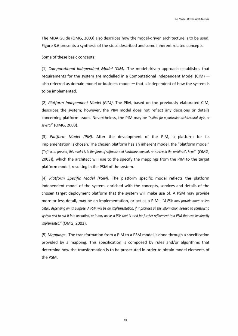
3.3 Model-Driven Architecture
59
The MDA Guide (OMG, 2003) also describes how the model-driven architecture is to be used.
Figure 3.6 presents a synthesis of the steps described and some inherent related concepts.
Some of these basic concepts:
(1) Computational Independent Model (CIM). The model-driven approach establishes that
requirements for the system are modelled in a Computational Independent Model (CIM) ─
also referred as domain model or business model ─ that is independent of how the system is
to be implemented.
(2) Platform Independent Model (PIM). The PIM, based on the previously elaborated CIM,
describes the system; however, the PIM model does not reflect any decisions or details
concerning platform issues. Nevertheless, the PIM may be “suited for a particular architectural style, or
several” (OMG, 2003).
(3) Platform Model (PM). After the development of the PIM, a platform for its
implementation is chosen. The chosen platform has an inherent model, the “platform model”
(“often, at present, this model is in the form of software and hardware manuals or is even in the architect’s head” (OMG,
2003)), which the architect will use to the specify the mappings from the PIM to the target
platform model, resulting in the PSM of the system.
(4) Platform Specific Model (PSM). The platform specific model reflects the platform
independent model of the system, enriched with the concepts, services and details of the
chosen target deployment platform that the system will make use of. A PSM may provide
more or less detail, may be an implementation, or act as a PIM: “A PSM may provide more or less
detail, depending on its purpose. A PSM will be an implementation, if it provides all the information needed to construct a
system and to put it into operation, or it may act as a PIM that is used for further refinement to a PSM that can be directly
implemented.” (OMG, 2003).
(5) Mappings. The transformation from a PIM to a PSM model is done through a specification
provided by a mapping. This specification is composed by rules and/or algorithms that
determine how the transformation is to be prosecuted in order to obtain model elements of
the PSM.

3 Model-Driven Development
60
Mappings
Mappings can fundamentally be categorized on two types: model type mappings and model
instance mappings.
then perform
MDA
Objectives Core concepts How to
defines has prescribes
Build a CIM
start by
Build a PIM
Build a PSM
followed by
Direct transformation
into code
Platform model
Mappings
Model type
mappings
Metamodel
mappings
Other type
mappings
Model instance
mappingsCombined model type
and instance mappingsMapping language Templates
Marks
Mark
model
involves to choose a
then define
can be
can be
will define
can also be specified by a
is specified using acan also include
Transformation
has as results
PSMRecord of
transformation
followed by
or
Figure 3.6 - How MDA is to be used.
Model type mappings
Model type mappings specify mappings based on model types of the PIM and PSM languages.
Being based on types, this kind of mappings consequently specifies transformations that
apply to all respective instances. Metamodels mappings − in which “the types of model elements in
the PIM and the PSM are both specified as MOF metamodels” (OMG, 2003) −, are examples of model type
mappings.

3.3 Model-Driven Architecture
61
Besides metamodel mappings, other model type mappings may exist, as there may be the
case where the types available on the PIM or PSM may be not expressed as MOF
metamodels, but in other languages, eventually in natural language. Still in this case, the
mapping can also be realized between those instances types.
Mappings rules may also be expressed according to instance values or patterns of type usage
found in the PIM model. Figure 3.7 illustrates model type mappings.
meta-metamodel
metamodel
model
data
PIM PSM
model type
mappings
The metamodel may be:
- a MOF compliant metamodel,
- or composed by types expressed in other languagesma
pp
ing
rule
s
- transform directly, or
- transform according to instance values, or
-transform according to pattern of type usage
Figure 3.7 - Model type mappings.
Model instance mappings
Model instance mappings are defined with the purpose to define particular transformations
to apply to some of the model elements of the PIM. In these kind of mappings, marks - “which
represent concepts in the PSM” (OMG, 2003) - are applied12 to model elements of the PIM with the
primarily purpose to indicate how those model elements of the PIM should be transformed
(see Figure 3.8) or, eventually, to specify quality of service requirements on the
implementation (instead of specifying the target of transformation, leaving it to the
transformation itself, which based on the requirement specified chooses the appropriate
target).
A set of marks may be provided by a mark model which, being independent of any particular
mapping, can be used in different mappings; if necessary, marks may have parameters.
12 A mark is platform specific and is not part of the PIM (marks can be though as being applied to a “transparent layer” placed over the model.)

3 Model-Driven Development
62
As a result of the process of marking PIM elements to be subject of particular
transformations, a PIM element can be marked once or eventually, marked several times,
which in this case, will have several marks associated to it. In the latter case, it means that
the element participates in several mappings and it shall be subject of each of the
transformations associated with the mappings.
A mapping may involve several marked PIM elements; in this case each mark indicates the
role that the PIM element is to accomplish on the mapping.
meta-metamodel
metamodel
model
data
PIM PSM
model instance
mappings
ma
pp
ing
rule
s
Marked PIM
Platform model
Figure 3.8 - Model instance mappings.
Languages and templates
Transformations described in mappings13 are expressed in some language. This description
may be “in natural language, an algorithm in an action language, or in a model mapping language.” (OMG, 2003).
A mapping may include templates, which are “which are parameterized models that specify particular kinds
of transformations” (OMG, 2003). In model type mappings, they can be used in rules to drive the
transformation of a pattern of model elements into another pattern of models elements
(Figure 3.9).
13 Mappings may also consist of the combination of the approaches described − instance and type mappings.

3.3 Model-Driven Architecture
63
In model instance mappings, a template may have associated a set of marks in order to either
specify instances that shall be transformed according to the template, or to provide values to
parameters of the template (Figure 3.10) (OMG, 2003).
ma
pp
ing
rule
s
metamodel
model
PIM PSM
Templates in
model type
mappings
mapping including template
Figure 3.9 - Templates in model type mappings.
Model transformation
Model transformation generally refers to the process of converting a PIM, or a marked PIM,
into a PSM. This process can be done manually, with or without computer’s tools support, or
automatically.
ma
pp
ing
rule
s
metamodel
model
PIM PSM
mapping including template
Templates
with an
associated
set of marks
Figure 3.10 - Templates with an associated set of marks.

3 Model-Driven Development
64
Typically, the model transformation process has as inputs the PIM/marked PIM and the
mappings to be followed, and produces as output the PSM and a record of the
transformation (showing the PIM elements and the associated resulting PSM elements
produced in the transformation). This process is illustrated in Figure 3.11.
Figure 3.11 - Model transformation.
In model type transformations, which are based on type information, a target model is
automatically generated; nevertheless, “the transformation tool asks a user for mapping decisions in the course
of transformation where a rule specifies that information not available in the source model is required, and records those
decisions as marking of the PIM.” (OMG, 2003).
The approaches used to the transformation of models can broadly be synthesized in: (i)
transformations based on a marked PIM (with or without combination with model type
mappings) and its marks of instance mappings; (ii) transformation based on PIM and its types
mappings, which rely on metamodels or types (not defined by an explicit metamodels).
An alternative approach to model transformation is the direct transformation into code,
which does not produce the PSM. Instead, it transforms the PIM directly into code on the
chosen platform, as illustrated by Figure 3.12.
3.4 Research Efforts
Automation, which includes complete code generation and execution of models, is a key
premise behind MDD (Selic, 2003b). Tools must support the automation involved (in
particular any model transformations) in order to make model-driven development a reality
PIM
or
Mappings
PSM
Record of the
Transformation
Marked PIM
Model Transformation

3.4 Research Efforts
65
(Sendall & Kozaczynski, 2003) and thus allowing for the collection of the full benefits of this
approach to software development.
Beyond automation, other issues are considered pertinent to the success of MDD. The
following paragraphs expand, besides automation, these issues.
Figure 3.12 - Direct transformation to code.
(1) Automation. Automation represents “the most effective technological means for boosting productivity and
reliability” (Selic, 2003b) and contributes to the enrichment of models’ role on software
development, taking those from a role of merely documentation support (and usually on
divergence from reality). It “formalizes solutions and raises the level at which we can apply creativity” (Mellor,
et al., 2003), and contributes, beyond the support to vertical and horizontal model
synchronization, to “significantly reduce the burden of other activities, such as reverse engineering, view generation,
application of patterns, or refactoring” (Sendall & Kozaczynski, 2003). Software modelling and
automatic code generation had few success in the past, being these limited to diagramming
support and skeletal code generation, which were not enough to provide a relevant
productivity return (Selic, 2003b). However, technology and knowledge have evolved, and
today, beyond a better understanding of modelling, automation technologies have matured
PIM
or
Mappings
PSM
Record of the
Transformation
Marked PIM
Model Transformation
Code Generation
Code
Direct
Transformation
to Code
Models
Code
Approach of direct
transformation into codeApproach of model transformation

3 Model-Driven Development
66
and world-wide accepted standards have emerged, such as those provided by the Object
Management Group − such as the Unified Modelling Language (UML) or the Meta-Object
Facility (MOF) (or de facto standards, such as Extensible Markup Language (XML) and Simple
Object Access Protocol (SOAP)), contributing for a better MDD positioning to be succeed in
the software development (Selic, 2003b). Selic (Selic, 2003a) understand that the most
benefits of model-driven development are reached when MDD methods offer the capabilities
of: (i) automatic code generation of the implementation from the corresponding higher-level
model, meaning that “the model and implementation are one”; (ii) execution of models, which allows
for the experimentation with models to acquire knowledge, in a quickly and inexpensive way,
of a system’s properties. Atkinson and Kunhne (Atkinson & Kuhne, 2003) also refer an goal of
MDD the automation of “many complex (but routine) programming tasks –…– which have to be done manually
today”. For these capabilities, the modelling languages used “must have the same semantic precision as
programming languages” (Selic, 2003a) (which doesn’t necessarily mean having the same detail).
(2) Tools. To MDD’ success, Selic (Selic, 2003b) calls attention to the importance of getting
attention to issues, other than ”defining suitable modelling languages and automatic code generation”,
namely, the need of tools that come in pragmatic support of model-driven development.
Several tools are needed to support usefully support MDD, such as: (i) model-level reporting
tools, to assist on the reporting and the debugging of errors at model-level, in analogy to
what happens with traditional programming language compilers and debuggers; (ii) model-
merging tools to enable the possibility to merge two or more models; (iii) model difference
tools to help to identify differences between two models; (iv) the possibility of execution of
models (eventually incomplete), in a simulation environment or in the target platform, allows
for early experimentation of the system under development, to analyse high-risks aspects or
alternative candidate solutions.
(3) Code generation. Efficiency of code generation from models does not represent a primary
concern, since current technologies can generate code with “both performance and memory efficiency
factors are, on average, within 5 to 15 percent (better or worse) of equivalent manually crafted systems” (Selic, 2003b).
Generating complete code from models isn’t technically easy, but the same happened with
code compilers when they initially introduced in the past. Nowadays, efficiency of generated
code is typically not questioned; the same is to be expected one day of code generated from
models (Selic, 2003b). Whilst there may be eventual situations where hand-crafted code may
be needed, it is expected that for next years this efficiency improves as technology gets
evolved.

3.4 Research Efforts
67
(4) Produtivity. In order to increase productivity, Atkinson and Kuhne (Atkinson & Kuhne,
2003) understand that model-driven development approaches must take into account
changes that affect longevity of software artefacts. These changes are considered in “four main
fundamental forms”: (1) in personnel - developers have important development knowledge, and
if not prevented, personnel fluctuations may lead to the loss of some of this knowledge; (2) in
requirements - there is an ever-increasing rate of new features requirements demanded for
the system, with the restriction of minimal system interruption or change impact; (3) in
development platforms - it is convenient that attention be provided so that the software
artefacts don’t become exclusively tied to a proprietary development tool, platform or
environment; (4) in deployment platforms - new technological platforms are always emerging
which may imply changes to software artefacts, and so, the development of those must take
this in consideration in order to increase their longevity. These kinds of changes, which can
occur concurrently, lead to several needs that must be addressed by MDD infrastructures in
order to decrease the sensitiveness to change of software artefacts. These needs include: (i)
software artefacts described with clear and concise concepts, and with an understandable
notation accessible to a wide range of people; (ii) high interoperability of tools and artefact
storage on well-established non-proprietary formats; (iii) user-defined mappings to shield
models from specifics of technological platforms. To attend these needs, it becomes
convenient to MDD supporting infrastructure techniques as visual modelling (as a way of
effectively using human visual perception), object-orientation (support for dynamic user
extensions to model concepts) and metalevel description techniques (allows to fully
customize models to specific domains) (Atkinson & Kuhne, 2003).
(5) Scability. MDD can be applied to large-scale applications (“the largest systems developed to date
using full MDD techniques have involve hundreds of developers working on models that translate into several millions of lines
of standard programming language” (Selic, 2003b)), so it is necessary to take some attention to
scalability issues in compilation time. Turnaround time, due to frequency of small changes,
gets an important focus over the full-system generation time, requiring that “code generators have
a sophisticated change impact analysis capabilities in order to minimize the amount of code regeneration”. The
compilation phase − compiling program code using standard programming language
compilers − is “significantly longer” than the code generation phase − translating models into code
in some programming language (Selic, 2003b).

3 Model-Driven Development
68
3.5 Conclusion
To deal with the increasing complexity and demands of software systems (“The developed
economies rely at a large extent on software…” (Miller et al., 2004b)), software engineers have resorted
to models to increase the level of abstraction, and, in an elaborated and meaningful way, to
abstract the details of the system through focusing on the select parts of the system under
analysis or design. With models, software engineers, as engineers in other disciplines, expect
to be driven to an easier way to conceive, develop, maintain, or integrate a system.
Additionally, and in opposite to other disciplines, it is possible to automate some construction
of the foundations of the applications.
An appropriate approach to software development and correct use of modelling techniques,
jointly with effective tool support, consistent and comprehensive systems models can be
conceived, will ultimately allow for the possibility to deploy the same system to another
target technological infrastructure with no modifications on the original model of the system.
Nevertheless, as stated on the vision of Object Management Group (OMG)14 (OMG, 2005a)
regarding to the development of software systems, the manifold modelling languages and its
notations, along with imprecise and insufficient concepts and semantics, as well as a difficulty
on keeping up to date the developed system’s models, drove to an unbelief on the real
benefits of broad adoption of models in software development. As modelling languages have
coalesced and converged to a unified notation (as the Unified Modelling Language (UML)
(OMG, 2005b)), the focus of efforts turned into the evolution of one language and to creation
of tools to its support on the development of software systems. Models become again focus
of attention with the hope that, along with other meanwhile emerged standards, it can be
now possible to accomplish the expected benefits of using models.
14 OMG is a non-for-profit software consortium that produces efforts aiming on reducing the complexity, lower costs and to hasten the introduction of new software applications. OMG produces specifications through an open and vendor neutral process which proposes and invites proposals and feedbacks.

Chapter 4
Presentation of the Projects
Chapter Contents
4 Presentation of the Projects .................................................................................................................. 71
4.1 Introduction .................................................................................................................................... 71
4.2 Presentation of the uPAIN Project .................................................................................................. 73
4.3 Presentation of the USE-ME.GOV Project ....................................................................................... 81
4.4 Common Facts, Issues and Challenges ............................................................................................ 95
4.5 Conclusion ....................................................................................................................................... 97

70

4
Presentation of the Projects
This chapter presents the two projects used in this thesis. The first project presented
is the uPAIN project (Ubiquitous Solutions for Pain Monitoring and Control in Post-
Surgery Patients) and the second project is the USE-ME.GOV (USability-drivEn open
platform for MobilE GOVernment) project. For each project, it is presented a brief
introduction to the project and a description under pervasive and modelling
perspectives.
4.1 Introduction
This chapter starts by presenting two projects developed in the field of ubiquitous and mobile
computing that directed their software development to a model-based/driven approach.
The first project presented is the uPAIN project (Ubiquitous Solutions for Pain Monitoring and
Control in Post-Surgery Patients). It was conceived with the purpose to create a networked
informational computing system that, making using of current wireless and mobile
communication technologies, allowed to enhance hospital’s anaesthesiology services on the
control and monitor at pain level on post-surgery (uPAIN). It aims to enable for better
assessment and treatment of the pain phenomena by the hospital staff. It was submitted
(and accepted) as proposal (uPAIN) to the Agency of Innovation (Adi) (Adi) in scope of the
Program IDEA. The IDEA program aimed to stimulate the cooperation between enterprises
and the Scientific and Technological National System (SCTN)’s entities in order to enhance
results and technological transfers from STCN entities to productive sector. The uPAIN project

Presentation of the Projects
72
was framed on the area of Information and Technology Systems and developed by its
consortium’s partners for a three years term (initially project to the time interval ranging
from 1st October 2003 to end in September 2005). The scientific research and technological
development entities forming the consortium responsible for the project prosecution were:
University of Minho, through its Information System’s Department (UMinho-DSI); MobiComp
(MobiComp), a Portuguese mobile computing and wirelesses solution’s provider; and the
Hospital “Senhora da Oliveira”, localized on the city of Guimarães, Portugal (HSOG).
The second project is the USE-ME.GOV (USability-drivEn open platform for MobilE
GOVernment) project that aimed to create an open platform for mobile government services
(USE-ME.GOV, 2003a). It was submitted as a proposal on the Sixth Framework Programme of
the European Union, under the Action Line “IST-2002-2.3.1.9 Networked business and
governments” (CORDIS), and was developed by its consortium’s partners for a two years term
(from 1st January 2004 until 28th February 2006).
The entities that formed the partnership of this project were, as research partners: EDISOFT 15(EDISOFT), a Portuguese company specialized on critical real-time command, control,
communications, computer and intelligence (C4I) systems; Retevísion Móvil, commonly
known as AMENA16 and at the time, the 3rd mobile operator in Spain; University of Minho (in
Portugal), through its research group GET (Telecomputing Engineering Group) (GET); Indra
Systems (Indra), a leading Spanish company in Information Technologies and Defence
Systems; Poznan University of Economics (in Poland), through its Department of Information
Systems17 (PoznanUE); Fraunhofer Institute for Applied Information Technology (FIT) (FIT) (in
Germany); Arakne (Arakne) an Italian software company focused on pervasive computing and
offering solutions in the healthcare, pharmaceutical, public administration, and bank fields;
and IntuiLab (IntuiLab), a French company specialized in human-computer interaction, and in
multimodality and mobility technologies. As end-user partners of USE-ME.GOV project were:
Vila Nova de Cerveira (VNC-ANMP; VNC-CM; VNC-RTAM), a small town (about 9000
inhabitants) in north of Portugal and at the border to Galiza (Spain); Formatex (Formatex), a
regional organization from the Spanish region of Extremadura, promoting interdisciplinary
scientific, technical and industrial research, and working on several fields related to
knowledge-based society; Gdynia (Gdynia), a city of Poland with about 255 000 inhabitants);
and Bologna (Bologna), the seventh largest city in Italy (with about 400,000 inhabitants).
15 As stated in the USE-ME.GOV project home page (USE-ME.GOV), EDISOFT acquired the Geograf, S.A. (which is mentioned in (USE-ME.GOV, 2003a) as a project participant and as belonging to the group PortugalSpace; PortugalSpace is by its turn referred as project participant on the project fact sheet (CORDIS)). 16 AMENA was acquired by France Telecom in 2005 (JornaldeNegócios, 2005), and is nowadays (ElMundo) called Orange (Orange). 17 At USE-ME.GOV project home page (USE-ME.GOV), this department is referred as “Department of Management Information Systems”.

4.2 Presentation of the uPAIN Project
4.2 Presentation of the uPAIN Project
The uPAIN project was developed for the anaesthesiology services of hospitals. It consisted of
an information system conceived to assist in monitoring and controlling pain of patients that
stay in a relatively long period of recovery after being submitted to a surgery. During this
period, analgesics are administered to them in order to minimize the pain that increases as
the effects of the anaesthesia gradually disappear. This administration of analgesics is
controlled by means of specialized devices called PCAs (patient controlled analgesia) based in
the personal characteristics of the patient and the kind of surgery to which the patient has
been submitted. The PCA can be described as “a medication- dispensing unit equipped with a pump attached
to an intravenous line, which is inserted into a blood vessel in the patient’s hand or arm. By means of a simple push-button
mechanism, the patient is allowed to self-administer doses of pain relieving medication (narcotic) on an ‘as need’ basis”
(Machado, Lassen, Oliveira, Couto, & Pinto, 2007).
The motivation of uPAIN project arises from the fact that different people feel and react
differently to pain, and there is a considerable variability of narcotic doses efficiency from
patient to patient. This makes anaesthesiologists interested in monitoring several variables in
a continuous manner during patients’ recovery, as it allows them to increase their knowledge
on what other factors, besides those already known, are relevant to pain control and in what
measure they influence the whole process.
The main idea behind the uPAIN system is to replace the PCA push-button by an interface on
a PDA (personal digital assistant) that, while still allowing the patient to request doses from
the PCA, create records in a database of all those requests along with other data considered
relevant by the medical doctors. uPAIN system was thus intended to provide a platform that
enabled for improvement of pain treatment services by allowing: (i) to establish automatic
regular assessment and registering of pain level, and to provide for an enhanced and faster
individual therapeutic prescription to pain symptoms; (ii) to provide support for written
therapeutic protocols and storage of the therapeutics treatment given to patients; (iii) to
facilitate to the Director of the Anaesthesiology Services: (a) the adjustment of the
monitoring and controlling equipment to the particular capabilities of each different person
composing his staff; (b) the supervision of all staff activities for nocturne or weekend periods.

Presentation of the Projects
74
4.2.1 The Pervasive Perspective
Figure 4.1 illustrates the architectural solution for uPAIN project. It reflects the devices and
communications technology needed to provide support for the information system that
accomplishes the functionality expected from the uPAIN system.
The uPAIN project connects, in a computer network system, the monitoring equipment and
the PCA (patient controlled analgesia), and support communication among staff and patients.
This enables, from the staff point of view, the ubiquity of the system’s functionality. A central
server (pSC) receives information sent by the patient PDA (pPDA). This server is responsible
for the management of all services provided by UPAIN. It provides support for data
acquisition from all medical equipment (like patient monitors and PCAs), for accessing
databases, and for managing requests from all the pPDAs (patient PDAs) and sPDAs (staff
PDAs).
The uPAIN system was conceived to allow for the hospital staff, through wireless networks,
to remotely control and monitor the pain even outside the hospital network (through mobile
phone networks).
Figure 4.1 - General architecture for the uPAIN system.

4.2 Presentation of the uPAIN Project
75
4.2.2 The Modelling Perspective
The uPAIN project emerged as an initiative in ubiquity arena, following as principles the
requirements management based on effective necessity and the derivation system’s
executable artefacts from transformation of system’s models. As such, an presentation of the
project development under a perspective of modelling development is henceforward done.
Considering that clients and developers have different points of view towards requirements,
two different categories for requirements were considered:
(1) User Requirements. User requirements result from an elicitation task focused in the
problem domain (aiming to acquire and understand the needs of users and project
sponsors with the ultimate purpose being the communication of these needs to the
system developers); they are typically described in natural language and informal
diagrams.
(2) System Requirements. System requirements result from developer’s effort to
organize user requirements at the solution domain. High-level abstract models of
system are used to establish and structure these requirements, and represent a first
system representation for use on design phase.
To describe the uPAIN user requirements, developers constructed several use case diagrams.
Figure 4.2 illustrates the contextual use case diagram that depicts the general functionalities.
Figure 4.2 - Level 0 Use Case diagram for uPAIN (from (uPAIN, 2005a)).

Presentation of the Projects
76
The use cases defined in this diagram were refined with additional use case diagrams. Figure
4.3 illustrates one of these use case diagrams.
{U0.1.1} Inject
Drug
{U0.1} Administer Drug
Patient
{U0.1.5} Configure
Drug Parameters
Medical Staff {U0.1.4} Validate
User
{U0.1.3} Manage
Drug Administration
«uses»
«uses»
{U0.1.2} Request
Bolus«uses»
PCA
«uses»
Figure 4.3 - Use case refined diagram for the “Administer Drug” use case (from (uPAIN, 2005a)).
The desired dynamic behaviour of the system regarding its functional interaction is further
illustrated, at the analysis phase, by several stereotyped versions of sequence diagrams built
by the developers. Figure 4.4 shows an example of a stereotyped sequence diagram.
sendRequest()
ProcessRequest()
Patient
{U0.1.2} Request
Bolus
{U0.1.3} Manage
Drug Administration
PCA Medical Staff
{U0.1.1} Inject
Drug
{U0.1.4} Validate
User
sendOrder()
requestMedicalDecision()
sendID(id)
sendOrder()
reconfigureDrugParams(id,params)
sendID(id)
{U0.1.5} Configure
Drug Parameters
sendConfiguration(params)
authorizeDrugAdministration(id)
[guard]
alt
[guard]
alt
{SD0.1} Bolus Request
inject()
inject()
setConfiguration(params)
Figure 4.4 - UML stereotyped sequence diagram for a uPAIN use case macro-scenario (from(uPAIN, 2005a))

4.2 Presentation of the uPAIN Project
77
These stereotyped versions only involve actors and use cases in the interactions. They allow
expressing “a pure functional representation of behavioural interaction with the environment and are particularly
appropriate to illustrate workflow user requirements”(uPAIN, 2005a) and facilitate the validation of user
requirements as they are easier understandable by the users. They differ from the traditional
sequence diagrams as these last ones already incorporate system objects, which imply
already modelled structural elements of the system.
Additionally to the specification of user requirements through use case diagrams, it was
considered relevant to give particular attention the validation of user requirements models.
uPAIN development approach considered that static requirements models, expressed
through use case models and stereotyped sequence, were not enough for having trustable
and clear requirements. This happens due the possibility of these diagrams not being fully
understandable by non-computer science educated stakeholders. These stakeholders may
have difficulties in finding and coping with the all inter dependencies between the
requirements that were elicited. Therefore, the approach, beyond using of static models to
express user requirements, developed animation prototypes to validate, through a dynamic
perspective, the user requirements.
Figure 4.5 shows an image of the animation prototype used for the uPAIN system user
requirements validation.
Figure 4.5 - Interactive animation prototype for uPAIN system (from (Machado, et al., 2007)

Presentation of the Projects
78
These animation prototypes present user-friendly visualizations of system behaviour. This
approach to validation was “experimented with and proved to be very effective” (Machado, et al., 2007),
promoting a deeper stakeholder’s involvement in the analysis phase and a better clarification
and elicitation of workflow requirements.
The static user requirements models (use case and stereotyped sequence diagrams) were
used to derivate, through intermediating Coloured Petri-Nets (CPNs), the animation
prototypes. Figure 4.6 presents a CPN responsible for the animation prototype interaction
related to a use case of the uPAIN project.
Figure 4.6 - CPN responsible for the prototype animation of a use case (from (Machado, et al., 2007)).
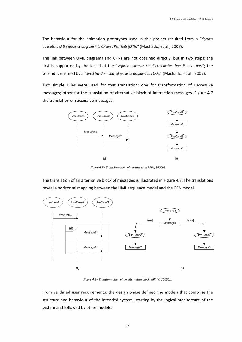
4.2 Presentation of the uPAIN Project
79
The behaviour for the animation prototypes used in this project resulted from a “rigorous
translations of the sequence diagrams into Coloured Petri Nets (CPNs)” (Machado, et al., 2007).
The link between UML diagrams and CPNs are not obtained directly, but in two steps: the
first is supported by the fact that the “sequence diagrams are directly derived from the use cases”; the
second is ensured by a “direct transformation of sequence diagrams into CPNs” (Machado, et al., 2007).
Two simple rules were used for that translation: one for transformation of successive
messages; other for the translation of alternative block of interaction messages. Figure 4.7
the translation of successive messages.
Message1
Message2
PreCond1
PreCond2
UseCase1
Message2
UseCase2 UseCase3
Message1
a) b)
Figure 4.7 - Transformation of messages (uPAIN, 2005b).
The translation of an alternative block of messages is illustrated in Figure 4.8. The translations
reveal a horizontal mapping between the UML sequence model and the CPN model.
alt
Message1
UseCase1
Message2
UseCase2 UseCase3
Message3
a) b)
Message1
Message2
PreCond1
PreCond2
Message3
PreCond3
[true] [false]
Figure 4.8 - Transformation of an alternative block (uPAIN, 2005b)).
From validated user requirements, the design phase defined the models that comprise the
structure and behaviour of the intended system, starting by the logical architecture of the
system and followed by other models.

Presentation of the Projects
80
The uPAIN project looked for the incorporation of principles of validation of requirements
and the derivation of system’s executable artefacts from transformation of system’s models.
To obtain the logical architecture from the validated user requirements, it was used the 4SRS
technique.
The 4SRS (4 Step Rule-Set) technique allows the transformation of user requirements into the
logical system-level architecture (here represented by an object diagram) representing
system requirements. Figure 4.9 presents the schematics of this technique; further
information on the 4SRS technique can be found on (J. Fernandes & Machado, 2001).
Figure 4.9 - 4SRS Technique (adapted from (J. Fernandes & Machado, 2001))
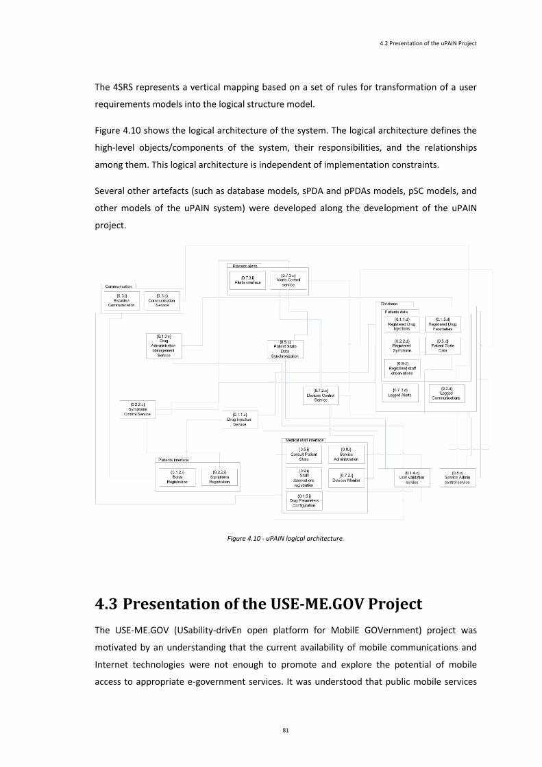
4.2 Presentation of the uPAIN Project
81
The 4SRS represents a vertical mapping based on a set of rules for transformation of a user
requirements models into the logical structure model.
Figure 4.10 shows the logical architecture of the system. The logical architecture defines the
high-level objects/components of the system, their responsibilities, and the relationships
among them. This logical architecture is independent of implementation constraints.
Several other artefacts (such as database models, sPDA and pPDAs models, pSC models, and
other models of the uPAIN system) were developed along the development of the uPAIN
project.
Figure 4.10 - uPAIN logical architecture.
4.3 Presentation of the USE-ME.GOV Project
The USE-ME.GOV (USability-drivEn open platform for MobilE GOVernment) project was
motivated by an understanding that the current availability of mobile communications and
Internet technologies were not enough to promote and explore the potential of mobile
access to appropriate e-government services. It was understood that public mobile services

Presentation of the Projects
82
should: (i) consider the specific needs and capabilities of different users; (ii) offer a high level
of usability and friendliness, taking into account context of users; (iii) be easy to configure
and to deploy, and to be not dependent on expensive hardware, software, or demanding
specialized skills by sharing the use of technical resources and skills; (iv) ease the promotion
of services of local companies and public initiatives (USE-ME.GOV, 2003b).
The USE-ME.GOV project focused on the development of a ”new open platform for mobile government
services, supporting usability, openness, interoperability, scalability, thus facilitating service deployment and access, as well
as attractive business models satisfying service providers, public authority and citizens”(USE-ME.GOV, 2003b). This
platform was intended to facilitate the access of authorities to the mobile market by allowing
them to share common modules (‘platform sharing’) and to deal with multiple mobiles
operators independently of each one’s interface.
Figure 4.11 and Figure 4.12 illustrate the concept of ‘platform sharing’ brought by the USE-
ME.GOV project.
Besides these main outcomes, the USE-ME.GOV project contemplated scientific and
innovation objectives: (i) to contribute to new generation of open service platforms for mobile
users; (ii) and to improve usability on mobile interfaces.
Figure 4.11 - Situation before USE-ME.GOV (USE-ME.GOV,
2003b).
Figure 4.12- Situation after USE-ME.GOV(USE-ME.GOV,
2003b).

4.3 Presentation of the USE-ME.GOV Project
83
The USE-ME.GOV system general architecture is illustrated by Figure 4.13. The design of the
USE-ME.GOV system was conceived to allow “the delivery of content and e-services to users who use variety
of mobile devices with different capabilities and connecting by various communication channels” (USE-ME.GOV,
2006). These services were designated as Added-Value Services (AVS) as they bring
additional value to the platform and are not an integral part of the platform; they are
delivered by third parties, and may be created “using virtually any technology and deployed on any machine
as long as its functionality is accessible via designed interface” (USE-ME.GOV, 2006).
The user connection to the platform is made through an access point that allows for
communication using a defined communication channel. The USE-ME.GOV Platform basically
consists of two separate application system: (i) Core Platform, which is responsible for user’s
platform access, user and terminal management; (ii) Service Repository, which is a central
registry of services.
Figure 4.13 - USE-ME.GOV System General Architecture (from (USE-ME.GOV, 2006))
The USE-ME.GOV system also contains what is designated by “platform services”: “services
provided either by the platform operator or third parties, which extend the functionality of the USE-ME.GOV platform (…)”
(USE-ME.GOV, 2006). Platform services included in the USE-ME.GOV system were: (i) Context
Provision and Aggregation Services; (ii) Localization Service; (iii) Content Provision and
Aggregation Service. These services enable the use of user’s context, user’s localization, and
access and aggregation of data form external sources.
Regarding the connectivity with external operators, it was developed interfaces for
connecting the USE-ME.GOV platform to the national mobile operators (for those operators
that do not have a ParlayX platform, specific connectors needed to be developed).

Presentation of the Projects
84
4.3.1 The Pervasive Perspective
The USE-ME.GOV system is a system that has to deal with potential heterogeneous cellular
devices of the users, which in time, is replaced by other more technologically evolved with
new capabilities or improved resources that enable them to be able to fulfil new
functionalities. USE-ME.GOV aims providing services availability everywhere in a particular
regions, taking into account the users’ context, and thus, simplifying users access. It can be
said that this availability is in the way towards service ubiquity.
The users, accompanying by its mobile terminals (Figure 4.14), move through diverse
locations and are exposed to different surroundings; consequently, users need information
and services related to their environment. Useful services take into account their contexts,
and facilitate the finding and provision of information and services. This represents an
opportunity to enhance the involvement and interaction of user with real environment: “A
compelling example is spontaneous community participation (Report complaint service), where the use of advanced mobile
technologies is much more than just an additional channel and aims to raise new applications areas. (…)” (USE-
ME.GOV, 2005)”
Figure 4.14 - User mobile access through cellular networks (adapted from (USE-ME.GOV, 2004b))
USE-ME.GOV provides for user context and localization information, and based in this
information, it turns out possible to find the most appropriate services for a user, and
proactively provide for relevant information to the user. Taking into account the
requirements of openness, usability, and interoperability, issues of relevance come about the
representation of heterogeneous mobile capabilities and user profiles, as well as context
information representation and services description and discovery.
4.3.2 The Modelling Perspective
The USE-ME.GOV project structured its development work in the following main tasks: (i)
scenario definition and evaluation task; (ii) a series of development and (integrated) research
tasks, typically disposed as “(…) traditional flow of activities for system development, known as waterfall model:
(…)” (USE-ME.GOV, 2003b). These development tasks encompassed activities for

4.3 Presentation of the USE-ME.GOV Project
85
requirements and analysis, preliminary design and Mock-up (where research activities took
place), detailed design and specification, implementation and integration and validation
tasks.
Scenario definition and evaluation task
Preceding the definition of the various scenarios of the added-value services, it was
performed an initial general requirement analysis for a first description of services and
general requirements that USE-ME.GOV system should conform to. This analysis
encompassed: (i) user requirements analysis; (ii) technical implementation requirements: (iii)
review of available business models; (iv) reviews of state-of-art on intuitive mobile interface
design and state-of-art on platform architecture and general design.
User requirements analysis aimed to describe the general service requirements and
constraints on the platform from the authority perspective (not the usability requirements
for the mobile user). It assembled “examples of potentially beneficial mobile services described by the end-user
partners”(USE-ME.GOV, 2004d). Technical implementations requirements took into account
the needs of the users of the services (public administration service providers, third party
providers, operators and citizens). It described the technical requirements for USE-ME.GOV,
such as the use of standards and proven technologies (J2EE, SML, etc.) and proposed an
architecture for USE-ME Platform and for AVS. Review of available business models aimed to
give “an overview of available business models in targeted markets such as public administration and mobile service
provision” (USE-ME.GOV, 2004c). Reviews of state-of-art on intuitive mobile interface design
and state-of-art on platform architecture and general design intended to bring a better
understanding of the corresponding current state and research activities. The former focused
on interaction styles, the latter focused on current trends in IT domains that can be of
interest to the definition of an open platform hosting mobile services (USE-ME.GOV 2004e;
USE-ME.GOV 2004h).
The consortium of USE-ME.GOV understood that the initial number of services with potential
interest to end-partners was too high for the scope and availability of resources of the
consortium project. Therefore, based on previous synthesis of service features from user
requirements analysis (USE-ME.GOV, 2004a), it was selected a restricted number of services
to be prosecuted in the project. These services were termed as “Pilot services”. The USE-
ME.GOV project provided several pilot services: (a) Healthcare service; (b) Mobile Student
service; (c) Report of Complaint service; (d) City Information service.
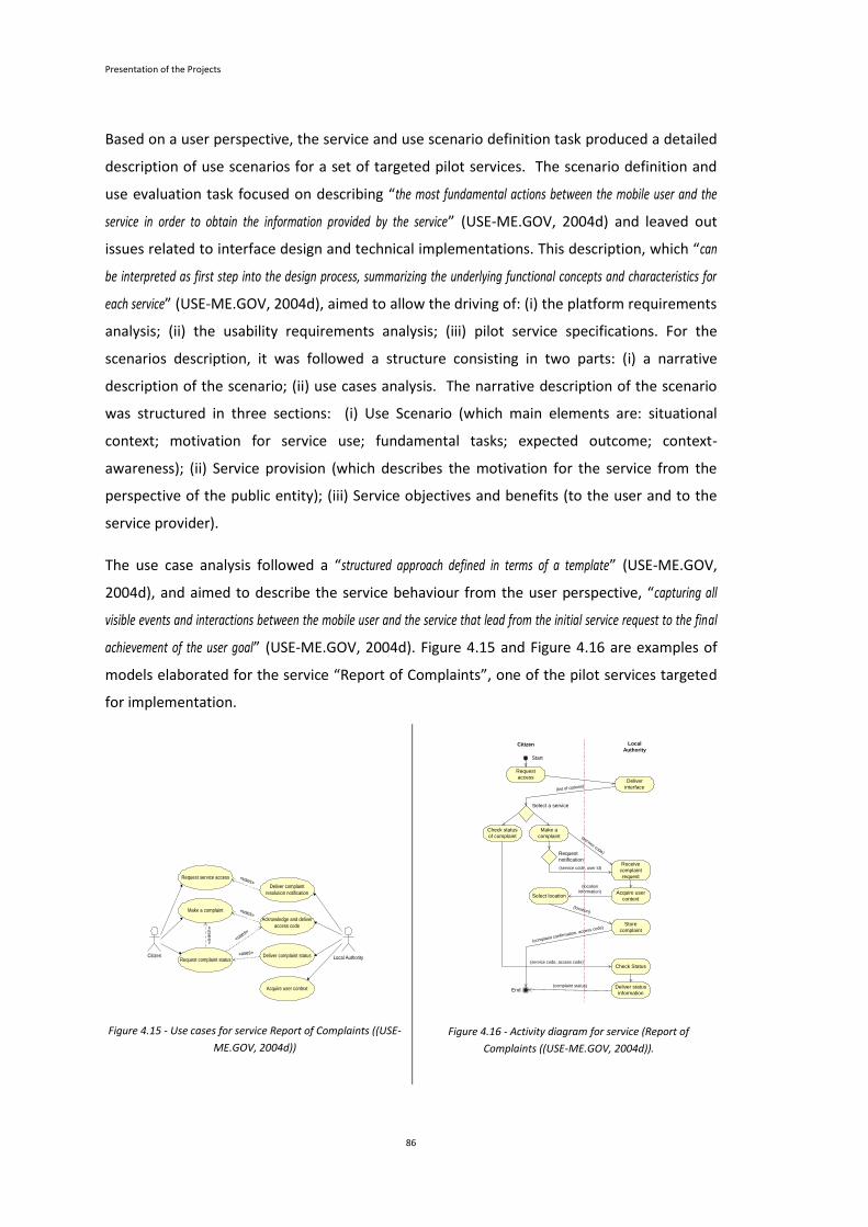
Presentation of the Projects
86
Based on a user perspective, the service and use scenario definition task produced a detailed
description of use scenarios for a set of targeted pilot services. The scenario definition and
use evaluation task focused on describing “the most fundamental actions between the mobile user and the
service in order to obtain the information provided by the service” (USE-ME.GOV, 2004d) and leaved out
issues related to interface design and technical implementations. This description, which “can
be interpreted as first step into the design process, summarizing the underlying functional concepts and characteristics for
each service” (USE-ME.GOV, 2004d), aimed to allow the driving of: (i) the platform requirements
analysis; (ii) the usability requirements analysis; (iii) pilot service specifications. For the
scenarios description, it was followed a structure consisting in two parts: (i) a narrative
description of the scenario; (ii) use cases analysis. The narrative description of the scenario
was structured in three sections: (i) Use Scenario (which main elements are: situational
context; motivation for service use; fundamental tasks; expected outcome; context-
awareness); (ii) Service provision (which describes the motivation for the service from the
perspective of the public entity); (iii) Service objectives and benefits (to the user and to the
service provider).
The use case analysis followed a “structured approach defined in terms of a template” (USE-ME.GOV,
2004d), and aimed to describe the service behaviour from the user perspective, “capturing all
visible events and interactions between the mobile user and the service that lead from the initial service request to the final
achievement of the user goal” (USE-ME.GOV, 2004d). Figure 4.15 and Figure 4.16 are examples of
models elaborated for the service “Report of Complaints”, one of the pilot services targeted
for implementation.
Citizen Local Authority
Request service access
Make a complaint
Request complaint status
Deliver complaint
resolution notification
Acknowledge and deliver
access code
Acquire user context
Deliver complaint status«uses»
«u
se
s»
«uses»
«uses»
«uses»
Figure 4.15 - Use cases for service Report of Complaints ((USE-
ME.GOV, 2004d))
Start
Request
accessDeliver
interface(list of options)
End
Citizen Local
Authority
Receive
complaint
request
Store
complaint
(service code)
Select location
Check status
of complaint
Make a
complaint
Request
notification
(service code, user id)
Acquire user
context
(location
information)
(location)
(complaint confirmation, access code)
Check Status
Deliver status
information
(service code, access code)
(complaint status)
Select a service
Figure 4.16 - Activity diagram for service (Report of
Complaints ((USE-ME.GOV, 2004d)).

4.3 Presentation of the USE-ME.GOV Project
87
Usability is defined based on ISO 9241-11 as: “the extent to which a product can be used by specified users to
achieve specified goals with effectiveness, efficiency and satisfaction in a specified context of use” (USE-ME.GOV,
2004e). It is noted that for mobile contexts, the usability analysis and design need to take into
account “mutable situations and goals, multitasking activities, simultaneous interaction with different devices and
mutable physical and social environments” (USE-ME.GOV, 2004e) and that these changes can occur
much more rapidly and frequently than in controlled and static environment. It is stated that
three dimensions of mobility affect the mobile experience as a whole: (i) device mobility,
regarding the continuous access to services while moving the device; (ii) user mobility,
referring to location and device independence service access; (iii) service mobility, regarding
to the capability to provide a service irrespective of user and device.
The main goal of the task of platform requirements analysis was “to define a logic architecture for the
system that could capture all its functional requirements and its non-functional intentionalities” (USE-ME.GOV,
2004g). Taking into account the work performed on the Service and Use Scenario Definition,
it aimed to “highlight the system requirements that can affect the appropriate decomposition of the system” (USE-
ME.GOV, 2004g). An object model and an informal description of the objects expressed these
system requirements.
The approach taken for the specification of the system requirements was based on the
methodology “4 Step Rule-Set (4SRS)” that guides the transformation of use cases into
objects. The main result of the application of this methodology was an object model at
system level. This approach requires that before applying the methodology, the functional
model (use case model) that reflects the system’s services must be defined.
User goals and corresponding scenarios definitions were translated into a set of use cases
describing the set of functional requirements applied to USE-ME.GOV. It was identified a “set
of functional requirements applied to a set of different application domains” (USE-ME.GOV, 2004g).
Two orthogonal criteria were defined to breakdown platform functionalities: (i) one
describing the main functionalities of the system (Figure 4.17 is an example of this criteria
application); (ii) the other one defining the different application domains (Figure 4.18
illustrates an example of this criteria application).
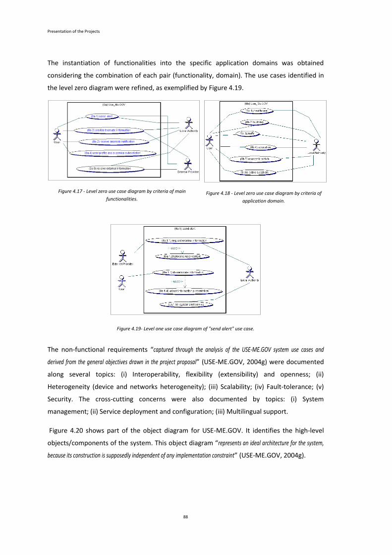
Presentation of the Projects
88
The instantiation of functionalities into the specific application domains was obtained
considering the combination of each pair (functionality, domain). The use cases identified in
the level zero diagram were refined, as exemplified by Figure 4.19.
Figure 4.17 - Level zero use case diagram by criteria of main
functionalities.
Figure 4.18 - Level zero use case diagram by criteria of
application domain.
Figure 4.19- Level one use case diagram of "send alert" use case.
The non-functional requirements “captured through the analysis of the USE-ME.GOV system use cases and
derived from the general objectives drawn in the project proposal” (USE-ME.GOV, 2004g) were documented
along several topics: (i) Interoperability, flexibility (extensibility) and openness; (ii)
Heterogeneity (device and networks heterogeneity); (iii) Scalability; (iv) Fault-tolerance; (v)
Security. The cross-cutting concerns were also documented by topics: (i) System
management; (ii) Service deployment and configuration; (iii) Multilingual support.
Figure 4.20 shows part of the object diagram for USE-ME.GOV. It identifies the high-level
objects/components of the system. This object diagram “represents an ideal architecture for the system,
because its construction is supposedly independent of any implementation constraint” (USE-ME.GOV, 2004g).
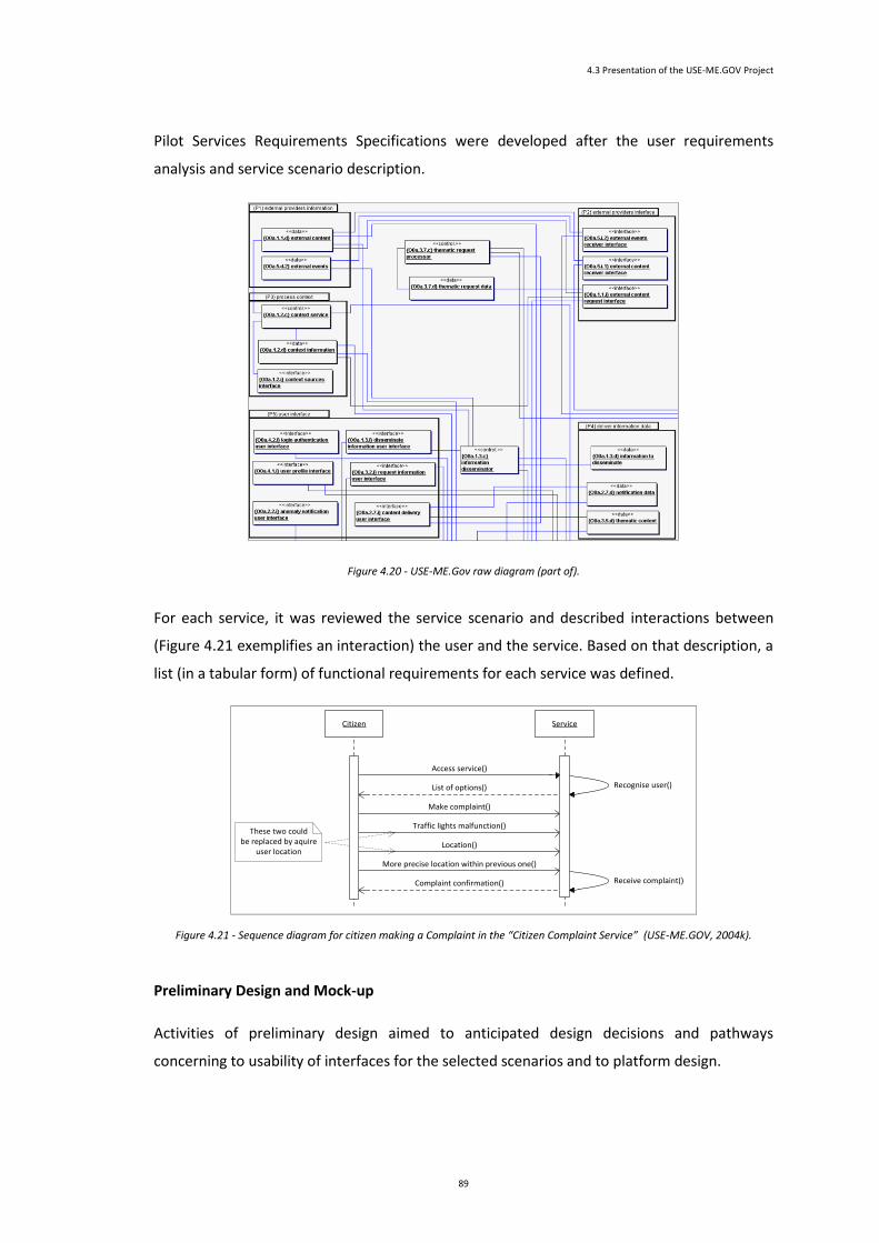
4.3 Presentation of the USE-ME.GOV Project
89
Pilot Services Requirements Specifications were developed after the user requirements
analysis and service scenario description.
Figure 4.20 - USE-ME.Gov raw diagram (part of).
For each service, it was reviewed the service scenario and described interactions between
(Figure 4.21 exemplifies an interaction) the user and the service. Based on that description, a
list (in a tabular form) of functional requirements for each service was defined.
Citizen Service
Access service()
Make complaint()
List of options() Recognise user()
Traffic lights malfunction()
Complaint confirmation()
Location()
More precise location within previous one()
Receive complaint()
These two couldbe replaced by aquire
user location
Figure 4.21 - Sequence diagram for citizen making a Complaint in the “Citizen Complaint Service” (USE-ME.GOV, 2004k).
Preliminary Design and Mock-up
Activities of preliminary design aimed to anticipated design decisions and pathways
concerning to usability of interfaces for the selected scenarios and to platform design.

Presentation of the Projects
90
The activities in preliminary design and mock-up were: (i) Platform Architecture Design Mock-
Up; (ii) Usability-Driven and Mock-Up Evaluation; (iii) Prototype Implementation and
Validation.
Figure 4.22 - Part of the “Report of Complaints Service” requirements (USE-ME.GOV, 2004e).
Regarding to user interface design, the approach was a usability-driven design and mock-up
for the user interfaces of the pilot service previously identified. These mock-ups were aimed
to allow the identification of critical design characteristics and the provision to project
partners with “preliminary design for the kind of service applications considered by USE-ME.GOV”(USE-ME.GOV,
2004f). The work in this task followed a design-evaluation-redesign cycle.
Platform Preliminary Design and Mock-up Evaluation had the objective of providing “a general
analysis of preliminary design of the Use-Me.Gov system together with the evaluation of mock-ups of the system (...) “
(USE-ME.GOV, 2004h). This preliminary design derived into an analysis model which was
intended to evolve later into a design model.
Figure 4.23 - High-level USE-ME.GOV diagram(USE-ME.GOV, 2004b)
Number Description
SR4-01 This service is available for all users in the platform. There is no need of registering this particular
service.
SR4-02 The service has the following options available:
- Make a complaint or suggestion
- Request voice call from PA to specify details of the complaint
- Request list of complaints. Within this one:
- Request for complaint status
- Request for complaint follow-up reports
- Cancel a complaint
SR4-03 When the PA receives a complaint it may call the user (voice call) in order to obtain more detailed
information even if the user didn’t requested it.
SR4-04 When making a complaint the user selects the kind:
- Holes on the street
- Holes on the side walk
- Electricity and illumination poles
- Garbage collectors damaged or full
- Traffic Lights malfunction

4.3 Presentation of the USE-ME.GOV Project
91
In a posterior document called “Platform Architecture Design” (USE-ME.GOV, 2004g), the
overview of the architecture of the USE-ME.GOV provided in this document was expanded
and deeper described/explained.
Figure 4.24 - Sequence diagram "Make complaint” (USE-ME.GOV, 2004b).
The Platform Architecture Design presented the fundamentals of the architectural design
established for the USE-ME.GOV system. It presented the reference architecture,
architectural factors and decisions that might have influence on the system architecture, the
functional perspective of the main components sub-systems, and the structure of systems
components (which were further detailed is a posterior task of detail design). The
architectural model of USE-ME.GOV has its foundations on the Web Services Architecture
(WSA) and in particular on Service Oriented Model. The USE-ME.GOV consists of the
following components (USE-ME.GOV, 2004i): (i) Core platform; (ii) Platform Services; (iii)
AVServices; (iv) Service Repository. Core Platform is the user entry point in the system. It
communicates with the user via mobile operator network and Internet; it dispatches to the
AVServices the incoming user requests. Platform Services are services registered within
Service Repository; they extend the standard set of platform functionality: “Platform Services
expose their functionality to other platform services as well as AVServices via common interfaces registered in the Service
Repository. (…) USE-ME.GOV is to provide minimal set of platform services (user localization, contextualization, content
provision, and content aggregation)” (USE-ME.GOV, 2004d). AVServices are services directly
accessible by end-users and that services their requests. Service Repository provides a
directory of services and allows for discovery and lookup of services.

Presentation of the Projects
92
Regarding system clients, the USE-ME.GOV platform aimed to work with heterogeneous
devices “regardless the different terminal capabilities arising from used: OS and software version, physical limitations
(like screen or keyboard size), and diversity of available bearers or communication channels.” (USE-ME.GOV, 2004d).
As such, it was chosen a thin client model as basis for the client application: “Platform Entry
Screens, Platform Administrative Screens (accessible by the user) and most of AVServices are designed to conform to micro-
browser specifications (…) ” (USE-ME.GOV, 2004d). Nonetheless, the platform was conceived to
support AV Services based on a thick-client model: “(….) AVService exposes interfaces which allow for
application download. In such a case [, the] platform role in the communication constraints to user authentication (granting
ticket). The client communicates directly with the AVService” (USE-ME.GOV, 2004d).
Figure 4.25 - User Management use
cases.
Figure 4.26 - Subscription states.
Figure 4.27 - Authenticate User activities
diagram.
The factors that might had influence on the architecture of the system were also presented in
a tabular describing the factor, its impact, and its solution. The functional perspective of the
USE-ME.GOV system regarding the Core platform and Service Repository was presented
through use cases models (use case diagrams, state chart diagrams, and activities diagrams
were used). Some examples of the diagrams elaborated are presented below. For Core
Platform the following diagrams are illustrated: use case diagrams (Figure 4.25), state chart
diagrams (Figure 4.26) activity diagrams (Figure 4.27).
For Service repository, Figure 4.28, Figure 4.29, Figure 4.30 illustrate use case diagrams for
service provision, service authentication and service authorization.
Detailed Design and Specification
The activities in Detailed Design and Specification were for: (i) Pilot Services Detailed Services
Specification; (ii) Detailed Components Interface and Application Specification; (iii) Meta
Protocol of Services Design; (iv) Platform Functional Design (an implicit research task).

4.3 Presentation of the USE-ME.GOV Project
93
The previous work on Pilot Services Requirements were, in a first phase, further described by
a Pilot Services Detailed Specification task (USE-ME.GOV, 2004l) and in a second phase,
detailed by a task of Platform and Application Detailed Design. The pilot services were, in
general, described and detailed with information/diagrams about a general description,
service architecture, data model, scenarios (expressed with sequence diagrams), and classes.
Figure 4.31, Figure 4.32, Figure 4.33, Figure 4.34, Figure 4.35 illustrate some of these
artefacts for the Complaint Service.
Figure 4.28 – Use case model for Service
Provision.
Figure 4.29 - Use case model for Service
Authentication.
Figure 4.30 - Use case model for
Service Authorization.
Figure 4.31 - High-level Service diagram (USE-
ME.GOV, 2004g).
+sendMessage(in platformMessage)
+processInteractiveRequest(in platformRequest, in userName, in terminalID, in terminalModel)
-getComplaintOptions()
-selectComplaintOption(in complaintOption)
-setVoiceRequest(in terminalID, in timeInterval)
-setDescription(in description)
-cancelComplaint(in complaintID)
-getComplaintUserList(in terminalID)
-selectComplaint(in complaintID)
-setComplaintNotification(in complaintID)
-getComplaintStatus(in complaintID)
-getLocationOptions(in userContext)
-selectLocation(in location)
complainInterface
-getComplaintChanges()
-receiveComplaintChanges()
notificationProcessor
+processContext()
-storeContext()
userContextInterpreter+PAsetComplaintOptions()
+PAupdateComplaintTI(in complaintID, in complaintStatus)
+PAgetComplaintList()
+PAselectComplaint(in complaintID)
localAuthorityInterface
-triggerComplaintChanges()
+store(in object)
+retrieve() : object
dbAccess
PA Complaint Application
AVService
Figure 4.32 - Service Architecture diagram (USE-ME.GOV, 2004g).
Figure 4.33 - Platfom interfaces to implement
(USE-ME.GOV, 2004g).
Figure 4.34 - Main menu user
interface (USE-ME.GOV, 2004g).
{01.2.3d} ComplaintDescription
PK ComplaintID
TerminalID
ComplaintDate
LastStatus
FK1 OptionID
PlatformRequest
ComplaintTypeID
FK1 ComplaintType
{01.2.1.d} ComplaintOptions
FK1 OptionID
ComplaintTypeID
Description
FK1 ComplaintType
{01.7.5.d}CancelComplaintData
PK CancelID
ComplaintID
CancelDate
Description
{01.4.d}TechnicaComplaintInformation
PK ComplaintID
StateChangeData
State
Expedition
Description
PAEmployee
{01.4.2d}VoiceCallRequest
PK VoiceReqID
FK1 ComplaintID
TerminalID
TimeInterval
TimeStap
PhoneNumber
{01.2.5.d}UserInformationData
PK TerminalID
TerminalModel
UserID
UserName
CreationDate
{01.1.d}ComplaintOptionInformation
PK OptionID
PK ComplaintType
ComplaintParameter
ParameterValue
Description
{01.3.1.d}UserContextData
ContextData
ComplaintID
FK1 TerminalID
{01.7.3.d}ComplaintStatusInformation
PK StatusRequestID
TerminalID
ComplaintID
RequestDate
Figure 4.35 - Data model diagram (USE-
ME.GOV, 2004g).
The Platform and Application Detailed Design detailed and complemented previous work
regarding USE-ME.GOV architecture and was intended to serve as basis for construction
phase of the project.
Useme
Plattform
AVService
PA
Complaint
Application
PA
Complaint
Report
Service
Interface Description/Implementation
public PlatformResponse
processIntaractiveRequest(PlatformRequest req, UserName
userName, TerminalID terminalID, TerminalModel
terminalModel) throws UserNotAuthenticatedException
Receive first contact from the platform to
the AVService.
This should be implemented in the
AVService component.
Additional description in [6].
public processMessage(PlatformMessage msg) This should be implemented in the
AVService component.
Additional description in [6].
public String getDescription() This should be implemented in the
AVService component.
Additional description in [6].
public XACML getAccessPolicySet() This should be implemented in the
AVService component.
Additional description in [6].

Presentation of the Projects
94
The USE-ME.GOV platform consists of two separate application systems, Core Platform and
Service Repository(USE-ME.GOV, 2005).
Figure 4.36 - USE-ME.GOV System General Architecture.
Figure 4.37 - Service Repository General Architecture.
The Core platform and Service Repository were organized through general subsystems/layers
diagrams and detailed through class and sequence diagrams (Figure 4.38, Figure 4.39 and
Figure 4.40 illustrates some of the diagrams elaborated for the Core platform).
Meta-Protocol of Service Types have had the purpose to define a framework for “meaningful
communication among platform components and dynamic services execution of services’ operations” (USE-ME.GOV,
2004j). Platform Functional Design concerns research activities and describes research
findings and decisions.
Figure 4.38 - Core Platform Layers View.

4.3 Presentation of the USE-ME.GOV Project
95
Implementation and integration and validation
Implementation and integration had the purpose to define the development environment,
the process for integration, the test plan, and perform the integration. Validation aimed to
specify how to validate the USE-ME.GOV system against the objectives.
Figure 4.39 - Class diagram for HTTP Server Adapter(Layer 1)
Figure 4.40 - Sequence diagram for doGet request of
HTTPServerInterface.
4.4 Common Facts, Issues and Challenges
This section aims to express particularities that are common to the projects and to anticipate
challenges that these kinds of projects seem to face, in order to better cope with the
consistent use of models and the specific characteristic of pervasive information systems,
such as resources heterogeneity and volatility of functionalities.
Despite of the significant difference of their size, it is possible to notice common facts about
the projects. Among these are the following:
They defined the overall process elements that sustain the software development
project.
They aimed to make use models along the project. The modelling language
generally adopted was UML (Unified Modelling Language), and they resort to use
case models for synthesizing functional requirements.
:
HTTPServerInterface
:
HTTPRequestProcessor
:
HTTPAccessPoint
: Connection :
ServiceRepositoryService
ServiceA :
AVService
doGet(javax.servlet.http.HttpServletRequest, javax.servlet.http.HttpServletResponse)
getConnection(javax.servlet.http.HttpServletRequest)
processHTTPRequest(javax.servlet.http.HttpServletRequest)
convertToPlatformRequest(javax.servlet.http.HttpServletRequest)
getServiceByRequestUri(String)
processInteractiveRequest(PlatformRequest, String, String, String)
AVService
PlatformResponse
convertToHttpResponse(eu.usemegov.coreplatform.common.PlatformResponse)
HttpResponseHttpResponse

Presentation of the Projects
96
They aimed to achieve ubiquity of the services. Services were conceived to be
accessible through common computer networks or cellular networks, allowing for
its users to access anywhere to the service.
They dealt with potentially heterogeneous devices susceptible to be replaced or
evolved. The cellular phones or PDAs are by its nature heterogeneous and
susceptible of frequent evolution.
They defined the main phases/activities of the process need to be executed in the
development process.
They use the 4SRS technique to achieve the transformation of requirements into a
first object model of the logical architecture of the system.
The observation of the projects revealed some come issues that may be pertinent to the
effectiveness of the fully adoption of strong model-based approach and to the suitability to
deal with some of the characteristic or pervasive information systems. Among these issues,
mainly due to an absence of detailing and formalization, are the following:
Some tasks are not explicitly defined in the project definition. They can be later
found in the development description or by the work products that come into
existence.
Some isolate but inappropriate use of process element terminology. It can be
found some misused of the conceptions process in the process definition.
Some lack of clearly separation and clarification of distinct activities and results.
Some lack of proper formalization in the project process of several work products.
Some lack of proper formalization of work products inputs and outputs of
activities.
It is not clear the interconnection of work products use in order to express model
navigation since the beginning to the end of the development.
It is not clear that there is suitable approach that takes in account the evolution of
the pervasive system, characterized by frequent addition and/or changes in
resources abilities and demanded functionalities.
Taken into account the facts and issues aforementioned, some challenges can be anticipated
in order to identify how these kinds of projects could enhanced in order to sustain an better a
proper software development project for PIS. The challenges can be stated by the following
needs:
The need to define the overall quality properties that a software development process
model-based/driven has to possess. Among these properties is the completeness of

4.4 Common Facts, Issues and Challenges
97
work and work products definition, the proper atomicity and level of activity
definition, the level of overall formalization of activities, the coherence, and
consistency of process elements’ use.
The need to express or formalize activities.
The need to be able to express and to measure the model-based/driven visibility.
The need to establish orientations or procedures to deal with aforementioned
characteristics of pervasive systems.
4.5 Conclusion
This chapter presented the two projects that were subject of this work. Both of them
consisted in a project developed in the field of ubiquitous and mobile computing that
directed their software development to a model-based/driven approach.
The first project presented is the uPAIN project (Ubiquitous Solutions for Pain Monitoring and
Control in Post-Surgery Patients). It was conceived with the purpose to create a networked
informational computing system that, making using of current wireless and mobile
communication technologies, allowed to enhance hospital’s anaesthesiology services on the
control and monitor at pain level on post-surgery (uPAIN). The second project is the USE-
ME.GOV (USability-drivEn open platform for MobilE GOVernment) project that aimed to
create an open platform for mobile government services (USE-ME.GOV, 2003a).
For each of the projects, it was presented the pervasive and modelling perspectives, which
expressed respectively the pervasive characterization and the modelling activities and
artefacts produced.
After that presentation of the projects, and as result from its observation some common facts
and pertinent issues were expressed. A reflection over those facts and issues lead to the
statement of some challenges that could anticipated for these kinds of projects, aiming to be
developed with a strong model basis and suitable to robust pervasive information systems.


Chapter 5
Approach to PIS Development
Chapter Contents
5 Approach to PIS Development............................................................................................................. 101
5.1 Introduction .................................................................................................................................. 101
5.2 Development Dimensions and Framework ................................................................................... 104
5.3 Extension to SPEM 2.0 Base Plugin Profile .................................................................................... 114
5.4 Approach to Software Development of PIS................................................................................... 117
5.5 Conclusion ..................................................................................................................................... 128


101
5
Approach to PIS Development
This chapter presents a conceptual development framework used to assist in the
analysis of the projects. The framework proposed, conceptions of functional profiles,
resources categories, and abstraction dimensions functional profiles instances, global
development process and elementary development process are introduced. Taking
into account the conceptions and structure, it is introduced a SEPM Base Plug-In
extension, a framing structure, and development framework pattern. These
conceptions and structures also constitute a basis for structuring a proper approach to
software development for PIS.
5.1 Introduction
Model-driven development (MDD) of software systems takes an approach to development
strongly based on models and transformations among models. Such approach: (i) allows
reduction of semantic gaps among the developed artefacts; (ii) enables higher independence
and resilience of domain models from particular characteristics and changes on system’s
technological platforms; (iii) promotes automation of the development tasks, enabling reuse
of knowledge relative to either best practice on software development or to the information
systems in the organization.
MDD topics of relevance are diverse and comprise different knowledge and techniques:
models, ontologies, modelling languages, domain-specific languages, development methods,
model transformations, architectures/frameworks, patterns, automatic code generation,

5 Approach to PIS Development
102
supporting tools, aspects, among others. It is expected that the application of MDD concepts
and techniques to software development for pervasive information systems (PIS), will
enhance the efficiency of the software development, the resilience, the robustness, and the
evolution of the system.
The approach to software development for PIS must take into account relevant
characteristics of PIS such as: (i) the elevated number of devices that can be involved; (ii) the
potential heterogeneity of the devices; (iii) the pace of requirements changes due
technological or business innovations; (iv) the potential complexity of interactions among
devices. Therefore, some issues that arise may influence the strategy taken on the approach
to MDD for PIS. The following paragraphs expose some of these issues.
In the same PIS, the devices can, simultaneously fulfil different functionality. Devices may
participate in several systems simultaneously, having identical functionality in some systems,
and different functionality in others. When activating a device on a PIS, the pervasive system,
attending to device’s characteristics and with a minimal configuration (on the system and/or
device), should be able to assign a suitable functionality (of interest to the system). The PIS
should then set up the needed reconfiguration/tune up of the system to allow integration of
the device in the normal operation of the pervasive system.
A device, along its life, can be enhanced with new capabilities, or be constrained on its
capabilities. As consequence, in order to reflect the change and accommodate the resulting
device capabilities, it is necessary to proceed with functionality reconfigurations.
Devices can be replaced for new devices. The replacement can be due to malfunction,
technologically outdate performance, energy consumption, capability, or change in business’s
processes, among others. Even when the devices are assigned to fulfil the same functionality
of the older devices, they may be based on different computational platform from the older
device. The functionality assigned to the old device must now be supported on a different
platform. The developed PIS must be able to accommodate easily platform changes on the
devices that integrate the system, and as such be able to deploy functionality on different
computing platforms.
Besides traditional coordination of system’s functionality and information’s flows,
independent and autonomous device-to-device interaction may be used to obtain additional
functionality to the system, allowing for, among others, enhanced system’s efficiency, and
robustness.

5.1 - Introduction
103
All these issues sustain the necessity of one being capable to conceive/change and deploy
software to devices in a way that allows easy accommodation of functional requirements
changes or technological platform changes. Supported by these issues, some questions
emerge regarding the construction of PIS, among which it can be found: (i) How to provide
for coherent and consistent construction, maintenance, and evolution pervasive information
systems that allows for proper accommodation of new or changed requirements,
functionalities, technology, or structure of devices composing the system? (ii) How to design
in order to simultaneously accommodate different functionalities on the same device? (iii)
How to design software for a PIS that, besides traditional coordination of system’s
functionality and information flows, allows specific device-to-device interaction to obtain
additional functionality? (iv) How high can be the abstraction level at which software
developers have to perform their main work? How should be an adequate approach suitable
to software development to PIS?
Pervasive information systems should be able to adapt to changes on the devices or on the
structure of devices that compose the system. The design of the PIS must encompass an
approach that recognizes those issues and that structures the needed concepts and adopts a
proper strategy that allow fast development/integration of new/changed functionalities.
These functionalities may correspond to new/changed system’s requirements, device’s
capabilities, or device’s computational platform technology.
MDD concepts and techniques centre development on models, thus raising the traditional
level of abstraction for system’s conception and design. They tend automate, as much as
possible, the transformation of models and the generation of the final code, and they provide
for a higher independence of the technological platform that support the realization of the
system. MDD seems to offer key pathways that enable software developers to cope with
complexity inherent do PIS. CASE tools, which are of primary importance to an effective MDD
development, have continuously evolved to support MDD concepts and techniques. It can be
expected from them an enhanced support to: creation, verification of PIMs and PSMs;
models’ transformations and code generations; changes’ management; and documentation
for all artefacts and to design decisions. However, spite of the fundamental effort of using
MDD concepts and techniques supported by suitable CASE tools, this is not sufficient. To a
proper construction of PIS, it is needed an approach that, while adopting modern and
appropriate MDD concepts, techniques, and tools, be capable of establishing a suitable
development’s strategy for the development of PIS, framed on appropriate structure and
procedures. The following sections expose the concepts, issues, and strategy that such
approach can assume.

5 Approach to PIS Development
104
5.2 Development Dimensions and Framework
Due to the complexity of pervasive information systems, software development for PIS can be
facilitated by an approach that properly focuses the system, and the system development,
with perspectives that help to abstract their relevant properties. The approach to PIS
development proposes a framework that encompasses concepts suitable for the model driven
development of pervasive information systems. This framework introduces and describes the
concepts sustained on a few perspectives of relevance to the development, called dimensions,
which are described in the sections that follow.
5.2.1 Resources Dimension
For a suitable organization and comprehension of the resources that PIS may comprise, it is
proposed that the resources to be used in the system (such as computational devices or other
entities able to perform activities), be grouped into resources categories. These resources
categories shall reflect common characteristics, properties, or capabilities of the resources,
which allow them to be generically able to take on identical/similar functional responsibilities.
Examples of groupings that form the categories, are the cellular phones, the smart phones, the
laptops, or others groupings. Figure 5.1 illustrates an example of categories and subcategories
of resources. Categories may be further classified through specialization relationships into
subcategories of resources.
Category A(PDAs)
Category B(smart and cellular phones)
Category C(PCs)
Category D(Server)
SubCategory B1(smartphones)
SubCategory B2(celular phones)
Category E(Embedded devices)
a11
a22
3a34a4
b1
b2
b3
b4
5
6
7
8a1
1
a22
3a3
4a4
b1
b2
b3
b4
5
6
7
8
Resources Dimension
Figure 5.1 – Resources dimension.
Resources belonging to a category (or subcategory) are expected to be able to support
common functionalities that may be assigned to that category. This perspective of looking for
and grouping resources constitutes the resources dimension.

5.2 Development Dimensions and Framework
105
5.2.2 Functional Dimension
The classification of resources into categories according to its properties or capabilities is just
one of the dimensions concerning to the global development of a pervasive information
system. The overall functionality PIS functionality can be seen as being achieved by the
collaboration of a set of functionalities projected in the PIS and that are assigned to its
resources; these thereby take on the responsibility to undertake those particular
functionalities. The resources have then a behaviour regulated by a set of functionalities
assigned to them as part of their responsibilities acquired from the PIS in which they
participate.
A set of functionalities, defined in the system for assignment to resources are herein termed of
“functional profile”. A functional profile is intended to be conceived and expressed, as far as
possible, in a resource independent form. Considering that a model is a (textual or graphical)
specification or representation, under some perspective, of a system, this resource
independent form can be seen as resource independent model. This perspective of defining
and viewing set of functionalities susceptible to be assigned to resources constitutes the
“functional dimension”. Figure 5.2 depicts this dimension.
Functional
profile 1
Functional
profile 2
Functional
profile ...
Functional
profile n
Funct
ional D
imensi
on
Figure 5.2 - Functional dimension.
This functional dimension brings the perspective of looking and seeing sets of functionalities
that can be allocated to resources for realization. Taking into account that resources are
grouped into categories, the assignment of a functional profile to a resource category has the
meaning that each resource in a certain category must be capable to realize the functional
profile assigned to the category.
Figure 5.3 illustrates the framing of the resources and functional dimensions. It shows the
functional profiles along the axis of the functional dimension, and the resources category along
the axis of the resources dimension.

5 Approach to PIS Development
106
Several functional profiles can be assigned to a category of resources, meaning that the
resources on the category must be capable, in principle, to somehow realize all those sets of
functionalities. F
unct
ional D
imensi
on
Resources Dimension
Functional
profile 1
Functional
profile 2
Functional
profile ...
Functional
profile n
Category A
(PDAs)
Category B
(smart and cellular phones)
Category C
(PCs)
Category D
(Server)
SubCat. B1
(smartphones)
SubCat. B2
(celular phones)
Category E
(Embedded devices)
a11
a223
a34a4
b1b2b3b4
5678
a11
a22
3a34a4
b1
b2
b3
b4
5
6
7
8
Figure 5.3 – Framing of Resources and Functional dimensions.
Some of the functional profiles assigned to a category may be redundant, as some of the other
categories (which have been specified as primary performers) that are in charge of servicing
those functional profiles may already provide them. Such situation may happen as result of a
design decision in order to accomplish specific objectives. Among these are: (i) to ensure
enhanced fault tolerance of crucial functionality; (ii) to expand system flexibility on services
provision; (iii) to accommodate functionality assigned to categories of devices that are
deactivated and marked for either replacement by new devices or subject to a technological
update.
The assignment of a functional profile to a resource corresponds to an instantiation of the
functional profile, carrying the meaning of responsibility assignment to that resource. The
instantiation process based on the functional profile and the resource category general
characteristic, results in a tailored functional profile for that resource category.
Figure 5.4 illustrates an example of instances resulting from the assignment of functional
profiles to resource categories. It particularly illustrates that it is possible to occur situations
where: (i) there are several instances for the same functional profile, as depicted by instances
2B and 2C (these are both related to functional profile 2, and to categories B and C
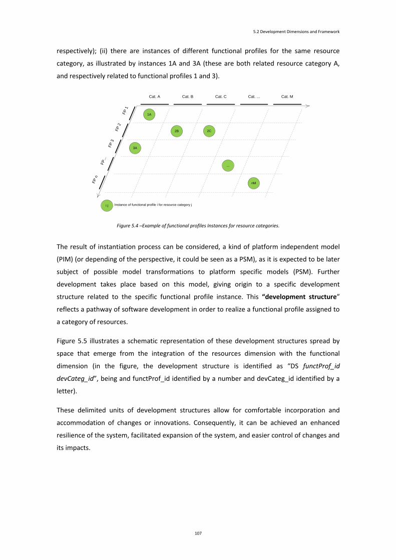
5.2 Development Dimensions and Framework
107
respectively); (ii) there are instances of different functional profiles for the same resource
category, as illustrated by instances 1A and 3A (these are both related resource category A,
and respectively related to functional profiles 1 and 3).
Cat. A Cat. B Cat. C Cat. ... Cat. M
FP
1
FP
2
FP
3
FP
...
1A
2C
FP
n
...
2B
3A
nM
i j Instance of functional profile i for resource category j
Figure 5.4 –Example of functional profiles Instances for resource categories.
The result of instantiation process can be considered, a kind of platform independent model
(PIM) (or depending of the perspective, it could be seen as a PSM), as it is expected to be later
subject of possible model transformations to platform specific models (PSM). Further
development takes place based on this model, giving origin to a specific development
structure related to the specific functional profile instance. This “development structure”
reflects a pathway of software development in order to realize a functional profile assigned to
a category of resources.
Figure 5.5 illustrates a schematic representation of these development structures spread by
space that emerge from the integration of the resources dimension with the functional
dimension (in the figure, the development structure is identified as “DS functProf_id
devCateg_id”, being and functProf_id identified by a number and devCateg_id identified by a
letter).
These delimited units of development structures allow for comfortable incorporation and
accommodation of changes or innovations. Consequently, it can be achieved an enhanced
resilience of the system, facilitated expansion of the system, and easier control of changes and
its impacts.

5 Approach to PIS Development
108
5.2.3 Abstraction Dimension
Taking into account that, for each development structure there is a subjacent top-bottom
abstraction course during its development, we can devise another dimension on software
development for PIS: the “abstraction dimension”. At the abstraction dimension, developers
use abstraction techniques to construct the systems. They have focus on PIM, PSM (and other
relative inner PIMs/PSMs), model transformations, code generation (see Figure 5.7), and
other techniques in order to come to a realization of a piece of software that meets the
functionality set by the corresponding functional profile of that development structure.
DS 1A
DS 2B
Funct
ional D
imensi
on
Resources Dimension
DS 2C
DS 3A
DS nM
Figure 5.5 - Development structures for functional profile instances.
For each of the development structures, development work is performed at a modelling level
of abstraction. Some modelling levels can be distinguished:
(1) Top modelling level. At this level, there is a PIM for each of category of resources. This PIM
results from instantiation of functional profiles models resulting from initial development of
the system as a whole (where all resources are integrated and orchestrated in order to provide
functionality to the system).
(2) Intermediate modelling levels. At these levels, there are PSM models that can be either
associated to subcategories of resources or to design decisions (reflecting particular choices
regarding to platforms, technologies or techniques) that may somehow introduce a certain
degree of platform/technological dependence.
Depending from the point of view, an intermediate model can be seen as a PIM or a PSM: a
model can be seen as a PSM when looking from a preceding higher abstraction model level,
and can be seen as a PIM when looking from next lower abstraction model level. For some

5.2 Development Dimensions and Framework
109
development structures these levels may eventually not exist, as it is possible to directly
generate the bottom-level PSM or even the code itself (in Figure 5.6, DS a, DS d, DS e do not
have intermediate model levels).
For illustration purposes, Figure 5.6 considers a simple case where a functional profile was
assigned to (and corresponding development structure created) each of the categories
represented. Nonetheless, a category may have several functional profiles, and consequently,
several development structures.
Category A PIM
(PDAs)
Category B PIM
(smart and cellular phones)
Category C PIM
(PCs)Category D PIM
(Server)
SubCategory B1
(smartphones)
PSM 1
SubCategory B2
(celular phones)
PSM 1
Category C
(design decision 1)
PSM1
Category C
(design decision 2)
PSM 2
Category E PIM
(Embedded devices)
a11
a22
3a34a4
b1
b2
b3
b4
5
6
7
8a1
1
a22
3a3
4a4
b1
b2
b3
b4
5
6
7
8
CategoryA PSM 2
(PDAs platform 2)
Category E
(Embedded devices
platform 1)
PSM 1
Category A PSM 1
(PDAs of platform 1)
SubCategory B1
(smartphones)
PSM 1.1
SubCategory B2
(celular phones)
PSM 1.1
Category C
PSM 1.1
Category C2
PSM 2.1
Category E
(Embedded devices
platform 2)
PSM 2
Model m
appin
g
Model m
appin
g
Code Generation
Mod
el m
appi
ng
Model m
appin
g
Mo
de
l m
ap
pin
g
Model m
appin
g
Mo
de
l m
ap
pin
g
Model m
appin
g
Mod
el m
appi
ng
Model m
apping
Model m
appin
g Model m
appin
g
a11
a22
3a34a4
b1
b2
b3
b4
5
6
7
8a1
1
a22
3a3
4a4
b1
b2
b3
b4
5
6
7
8
Top Level
Intermediate
Levels
Bottom Level
DS a DS b DS c DS d DS e
SubCategory B2
(celular phones)
PSM 1.2
Model m
appin
g
Category C2
PSM 2.2
Figure 5.6 - Structure of PIMs and PSMs inherent to the previous resources’s classification.
(3) Bottom modelling level. At this level, there are the lowest-level PSMs from which the final
code will be produced (either automatically generated or handcrafted). From a PSM, it may be
possible to derive one or more different code artefacts due to platform differences where the
code will be deployed; such task is delegated on the proper compiler or code generator.
A PIM may be directly transformed into code (or even eventually directly executed; in such
case there is no code generation), and therefore, there is no need to exist a PSM before code
generation, as illustrated by Figure 5.8.
The transformations between models are realized through model mappings. Two kinds of
model mappings can be identified in the development structures, namely, the vertical and
horizontal model mappings:
(1) Vertical model mappings. Between modelling levels, there are vertical model mappings,
these are based on well-established transformations that allows the mapping of a model into
an equivalent model at a lower abstraction level. This is the mechanism that brings a more
abstract system’s model to a more concrete and refined system’s model; this lower level

5 Approach to PIS Development
110
abstraction model may incorporate technological aspects and is nearer to final realization
(Figure 5.7 illustrates these kinds of mappings).
Code Generation
Category B PIM
(smart and cellular phones)
SubCategory B1
(smartphones)
PSM 1
SubCategory B2
(celular phones)
PSM 1
SubCategory B1
(smartphones)
PSM 1.1
SubCategory B2
(celular phones)
PSM 1.1
Mod
el m
appi
ng
Model m
appin
g
Mo
de
l m
ap
pin
g
Model m
appin
g
DS b
SubCategory B2
(celular phones)
PSM 1.2
Model m
appin
g
Ab
str
actio
n D
ime
nsio
n
Category D PIM
(Server)
DS d
Code Generation
Figure 5.7 - Illustration of the abstraction process. Figure 5.8 - Direct code generation.
(2) Horizontal model mappings. Horizontal model mappings are those mappings that, keeping
the models at the same modelling level of abstraction, have the purpose to achieve, through
specific transformations, other goals than the one of decreasing the abstraction level. For
example, these horizontal model mappings may be used to facilitate validation activities.
Figure 5.9 illustrates an example of horizontal mapping.
In synthesis, the tree dimensions pertaining to PIS software development are resources
dimension, functional dimension, and abstraction dimension, as depicted by Figure 5.10.
5.2.4 Development Framework
The dimensions and their concepts need to be integrated in a development framework for PIS.
A suitable development framework should consider issues concerning the overall system
development as well as issues concerning the development structures.
In (Booch et al., 2007), the concepts of “macro process” and “micro process” are used in the
framework proposed for the software development process. They represent perspectives of
the overall software development cycle (the macro process) and of the analysis and design
process (the micro process).

5.2 Development Dimensions and Framework
111
Whilst the macro process aims to guide the overall development of the system and its scope is
“from the identification of an idea to the first version of the software system that implements that idea” (Booch, et al.,
2007), the micro process cover the analysis and design activities. Activities of analysis focus on
behaviour and not on form, and produce an initial solution from system requirements.
Category A PSM
Category A
PSM 1
Model m
appin
g
Model m
apping
Code Generation
DS a
Category A PSM
Animation prototypes
for validation purposes
Category A
PSM 2
Model mapping
(horizontal)
Functional dim
ensio
n
Ab
stra
ctio
n d
ime
ns
ion
Devices dimension
Figure 5.9 – Example of a horizontal model mapping. Figure 5.10 - Dimensions on the development
approach.
Activities of design have the purpose to devise elements to provide behaviour and produces,
based in the results from analysis, a specification that can be implemented.
The macro-process presented is based on the RUP lifecycle (see Figure 5.11).
Figure 5.11 - Macro Process Milestones, Phases, and Iterations (from (Booch, et al., 2007)).

5 Approach to PIS Development
112
The micro process is performed in the context of the macro-process: the macro process “drives
the scope of the micro process, provides inputs to the micro process, and consumes the outputs of the micro process”(Booch,
et al., 2007). Figure 5.12 illustrates the bond between these processes.
Two dimensions are used to describe the macro-process: (i) the content dimension respects to
what is done (it can be described with disciplines and related notions as roles, tasks and work
products); (ii) the time dimension respects to when it is done (it can be described by
milestones, phases and iterations). The micro process is also described in terms of two
dimensions: (i) the level of abstraction, at which analysis and design activities are performed;
(ii) the content dimension, which considers two key areas of concern, the architecture and the
individual components.
Figure 5.12 - The Micro Process within the Macro Process (from (Booch, et al., 2007)).
The consideration of different process perspectives for the description of software
development, spite of not being coincident, it is also in the basis of the proposed development
framework. The development framework proposed follows two main perspectives: one
concerning the overall development process, and a second concerning to individual
development process associated to each of the functional profile instance. Figure 5.13
illustrates a schema of such framework.

5.2 Development Dimensions and Framework
113
Global development
process
Functional dim
ensio
n
DS a.1 DS b.1 DS m.1
D a.2
Resources dimension
Ab
stra
ctio
n d
ime
ns
ion
DS b.2 DS m.2
DS a.n DS b.n DS m.n
Elementary
development processes
Requirements Model
System
High-level System Model
Figure 5.13 - Development framework for PIS.
The “development framework” is essentially structured in a global development process and
several elementary development processes:
(1) Global development process. A global development process is responsible for modelling
requirements and for establishing high-level and global system models (such as the logical
architecture model of the whole system and the use case model of the system that expresses
the functionality expected from the system). From these, combinations of functional profiles
and categories of device are established, and the high-level PIM for each combination needed
on the system is specified. The global development process can establish milestones that each
individual structure development has to accomplish. The global development process has the
responsibility for making all the necessary arrangements for integration of the several artefacts
that result from individual threads of development and for final composition, testing, and
deployment of the system.
(2) Elementary development processes. Development structures do not have to follow the
same development process to carry out the development of that part of the system; for each
of the development structures, an adequate development process can be chosen, as long as it
respects the principles of the approach globally adopted. Therefore, elementary development
structures for functional profiles may be subject of their own thread of development process.
The implicit strategy to this development framework enables the adoption of development
process and techniques most suitable to development of that individual development

5 Approach to PIS Development
114
structure. It also eases the assignment of those structure units to different collaborating teams
and, eventually, the outsourcing of the development.
Besides the traditional documentation, the development approach should provide
documentation for each development structure. Among this documentation, it is expected to
be found information about the platform independent models (PIMs) at the top model-level,
the PSMs at the intermediate model-level, the PSM at the bottom model-level, the mappings
(either vertical or horizontal) and inherent transformation techniques used on the model’s
transformations, as well as information regarding to code generation. It becomes clear that it
is convenient the use of suitable CASE tools to support global and individual development
process developments as herein proposed. It is also expected the use of well-established
standards on languages and techniques for modelling (models and transformations models),
support for code generation, change management, and documentation of all artefacts and
design decisions.
The global process and the elementary process are not prescribed to be performed by any
particular existent development process, being the choice of process development left to the
developer. The global process can be see can be seen as being similar to macro process, as it
respect to the overall development process, and fed the elementary processes as the macro
also does for the micro process. The elementary process is somehow different from the micro
process as it has a distinct scope: it respects to a whole development structure, which can be
seen by itself as a system for which it can be applied a development process that can
inclusively include the strategy of development associated with the macro and micro concepts
presented.
5.3 Extension to SPEM 2.0 Base Plugin Profile
Software and Systems Process Engineering Meta-Model 2.0 (SPEM 2.0) provides to process
engineers a conceptual framework for modelling method contents and processes.
SPEM2. 0 is defined as a meta-model as well as a UML 2 Profile (concepts are defined as meta-
model classes as well as UML stereotypes). SPEM 2.0 meta-model describes the structures and
the structuring rules needed to express and maintain development method content and
processes. It is a MOF-based model and reuses some elements from UML 2 meta-model (key
classes from UML 2 Infrastructure (OMG, 2010)).
The SPEM 2.0 UML Profile provides an alternative representation to the SPEM 2.0 meta-model.
It defines a set of stereotypes that allows presenting SPEM 2.0 methods and processes using

5.3 Extension to SPEM 2.0 Base Plugin Profile
115
UML 2, and relies on the SPEM 2.0 meta-model to define all of its constraints. In addition to
SPEM 2.0 Profile, the specification also defines a “second non-standard convenience profile called ‘SPEM 2.0
Base Plugin Profile’” (OMG, 2008) that provides other useful stereotypes (OMG, 2008).
In the context of the approach presented for software development of pervasive information
systems, it is proposed additional stereotypes to this SPEM 2.0 Base Plugin. Next paragraphs
present these additional stereotypes; these are related to “Activity Kind” and “Work Product
Kind” stereotypes already defined in SPEM 2.0 Base Plugin.
Regarding to Activity Kinds, in addition to the predefined “Process”, “Phase”, and “Iteration”, it
is proposed the stereotypes “FrameworkSupport” and “Transformation” with its
specializations “ModelTransformation” and “CodeGeneration. Additionally, to the “Process”
Activity Kind, it is proposed as its specializations the “GlobalProcess” and “ElementaryProcess”
stereotypes.
Figure 5.14 illustrates the inclusion of these new Activity Kinds (in white boxes are the
predefined activities kinds; in grey boxes are the proposed additional activity kinds).
The purpose of each of the Activity Kinds stereotypes proposed is next briefly exposed:
“GlobalProcess”. The “GlobalProcess” stereotype allows the representation of a global
process that encompasses all the development of the system.
“ElementaryProcess”. The “ElementaryProcess” activity allows the representation of
processes of development occurring in the global development process and framed by
specific devised functionalities and resources categories.
“Transformation”. The “Transformation” stereotype is an abstract generalization
projected allowing to generically represent the activities of transforming models (or
other artefacts) either to other models or into code; these are, respectively,
represented by “Model Transformation” and “Code Generation” stereotypes.
“ModelTransformation”. The “ModelTransformation” stereotype intends to represent
activities that can be termed as model transformations.
“CodeGeneration”. The “CodeGeneration” stereotype intends to represent code
transformations activities (to source code, to executable code, or to other executable
artefact).
“FrameworkSupport”. The “FrameworkSupport” stereotype intends to represent
special activities related to deployment of the development framework, such as the
definition of the resources categories, the functional profiles, the functional profile
instances, or the elementary development processes.

5 Approach to PIS Development
116
«stereotype»
ActivityKind
«stereotype»
Process
«stereotype»
Phase
«stereotype»
Iteration
«stereotype»
GlobalProcess
«stereotype»
ElementaryProcess
«stereotype»
Transformation
«stereotype»
ModelTransformation
«stereotype»
CodeGeneration
«stereotype»
FrameworkSupport
«metaclass»
Classifier
Figure 5.14 – Inclusion of new Activity Kinds.
Regarding to Work Product Kinds, in addition to “Artefact”, “Deliverable”, and “Outcome”
stereotypes, it is proposed the addition of “FunctionalProfile”, “ResourceCategory”,
“FP_Instance”.
Figure 5.15 illustrates the inclusion of these new Artefact Kinds (in white boxes are the
predefined artefact kinds; in grey boxes are the proposed additional artefact kinds).
«stereotype»
WorkProductKind
«stereotype»
Artifact
«stereotype»
Deliverable
«stereotype»
Outcome
«metaclass»
Class
«stereotype»
ResourceCategory
«stereotype»
FunctionalProfile
«stereotype»
FP_Instance
Figure 5.15 - Inclusion of new Artefacts Kinds.
The purpose of each of the WorkProduct Kinds stereotypes proposed is next briefly exposed:
“ResourceCategory”. The “ResourceCategory” stereotype intends to representation of
a resource category.
“FunctionalProfile”. The “FunctionalProfile” stereotype intends to represent a
functional profile.

5.3 Extension to SPEM 2.0 Base Plugin Profile
117
“FP_Instance”. The “FP_Instance” stereotype intends to represent a functional profile
instance.
5.4 Approach to Software Development of PIS
This section aims, in the context the proposed approach, to provide a set of guidelines and
auxiliary tools to be used either to software development of new PIS or to analysis existing
projects developed on a model-based/driven basis and in context of a pervasive information
system. As a note, what is hereafter said about performing analysis can be applied to the
definition of new processes as long as the convenient considerations or adaptations are taken
into account.
In the context of a pervasive system, a development project based/driven by models should: (i)
stress out clearly the use of model transformation activities, activities interconnection, and
inputs/output of activities; (ii) provide a way to deal with heterogeneity and changes on the
resources on which software units are deployed for execution; (iii) provide a way to deal with
changes on the functionalities to be deployed on the resources. A development process can be
put in perspective through its activities or through the work. Therefore, an analysis approach
of model-based/driven projects for PIS can be sustained either by analysis of work products or
activities performed that promote the evolution of the system’s definition.
Software & Systems Process Engineering Meta-model Specification (SPEM) 2.0 (OMG, 2008)
can be used as an important auxiliary tool for the definition, diagnosis, and optimization of
processes. The system of concepts subjacent to its meta-model allows the capture of relevant
structure of existing processes for which one may want to deepen the knowledge. This
structure is a fundamental basis for observation and for analysis of the process, from which
further robust rationale can be realized about the process properties.
SPEM 2.0 specification provides, not only the metamodel, but also a set of corresponding
stereotypes of the metamodel concepts that can be used to easier illustrate the process
elements. Additionally, it also provides several examples of representation of workflow of
activities and work products, and of how these two representations can relate to each other
(including change of states of the work products).
The analysis of the projects, or the definition of new ones, has to take into account two
different points of view that highlight issues or peculiarities pertinent to model-based/driven
development and to pervasive information systems. These points of view are: (i) the pervasive
point of view, which takes into account elements relating to consideration of pervasive issues;

5 Approach to PIS Development
118
(ii) the model-based/driven point of view, which take into account elements related to the
models produced, model transformations applied, other modelling techniques/strategies or
conceptions used, and the suitability of the process approach utilised.
To pursuit this goal, it’s introduced: (i) the framing structure as an auxiliary tool for the
identification of the functional profile instances; (ii) a development framework pattern, which
to assist on the analysis an existing SPEM 2.0 development process diagram or to define new
projects based on the conceptions of the proposed approach.
The proposed approach for software development of pervasive information systems suggests a
strategy that assists in coping with the heterogeneity existing in pervasive systems and in
sustaining structurally model-based/driven software development. This strategy incorporates a
set of useful conceptions for its deployment; some of these conceptions were expressed in the
proposed extension of SPEM 2.0 Base Plug-In. This perspective searches for that parts of the
project model that may be potentially susceptible of application of those conceptions; these
parts are candidates for further attention as they may be subject of considerations and
eventual propositions for changes or enhancements.
The motivation for this perspective is twofold. First, to assist in identifying facts, issues, or
pertinent parts that have impact on the effectiveness of a strongly model-based approach and
on the suitability for dealing with pervasive information systems. Second, to contribute for the
improvement of software development of pervasive information systems and to exemplify, in
the projects, where and how this approach and its conceptions can be deployed.
How to do it? The analysis is based on the SPEM diagram of the project development process,
and as such, in the case that it does not exist, one must elaborate it. There are two levels of at
which the analysis/definition can be made: a structural level and a process’s element level. At
structural level, one has the purpose of: (i) fitting the structuring concepts of the framework
that give a basis to organize models development; (ii) copping with resources’ heterogeneity of
pervasive systems. At process’s elements level, one has the purpose to identify, enhance, or
promote work units to be formalized and defined, as far as possible, as transformations in
order to support an approach strongly based on models. The following paragraphs further
detail these issues.
Structural level
At a structural level, the main goals are to identify/establish a well-defined structure in
accordance to the proposed approach whose benefits were expressed in previous sections of
this document. Several conceptions were introduced earlier in this chapter and in previous
chapter; based on these, a crossing of conceptions can be made to produce useful result.

5.4 Approach to Software Development of PIS
119
Figure 5.16 depicts a conception crossing of instances of functional profiles for resource
categories, development framework for PIS, with the SPEM model of the project.
Global development
process
Functional dim
ensio
n
DS a.1 DS b.1 DS m.1
D a.2
Resources dimension
Ab
stra
ctio
n d
ime
ns
ion
DS b.2 DS m.2
DS a.n DS b.n DS m.n
Elementary
development processes
Requirements Model
System
High-level System Model
XX
Project Management
Management
Dissemination
Requirements Analysis and Elicitation
Characterization of the Environment
Elicitation and classification of user requirements
Formalization of system requirements
Refined Planning
Research and Technological Development
Definition of architecture's solution
Development of comPCA
Development of software for sPDAs pPDAs
Development of software for the pSC
Development of anesthesiology database
Technological integration and prototype installation
AV Communications (streaming)
Development of data mining techniques
Test and correction
Extension for GSM/GPRS/UMTS
Exploration and Evaluation of the Application
Characterization of the information system before the prototype
Exploration of the prototype
Evaluation of support offered by the system
Medical Research
Preparation of psycho-socio-cultural surveys
Execution of individual surveys to volunteers for test and improvement
Pain assessment in patients from HSO with uPAIN prototype
Context Diagram development
Use Case Diagrams development
Context Diagram
Use Case Diagrams [initial]
Problem Description
Use Case Diagrams development
Sequence Diagrams development
Use Case Diagrams [refined]
Sequence Diagrams
Petri lattices development CPNs
Refined activities plan
Components diagram
Executable prototype construction for requirements validation
Executable prototype for requirements validation
System architecture
System Requirements
Refined activities plan elaboration
Refined activities plan
Electrical and Electronic Project construction Electrical and
Electronic Project
Image processing software development Image processing software
comPCA
Software components development for sPDAs
Software components for pPDAs
Software components for sPDAs
Software components for pPDAs
Software for sPDAs and pPDAs
Software components development for PSC Software components
for PSC
Integration of sPC and SONHO DB Results from Integration with
SONHO DB
Software for PSC
Anesthesiology DB development
PHP application development
for surveys support
Anesthesiology DB
PHP application for surveys support
Anesthesiology DB
Technological
integraion
Prototype instalation
Prototype #1
Results from Prototype #1
installation
Prototype # 1 - initial version
Data mining techniquesData mining techniques development Data mining
techniques
Multimedia services development Multimedia services
Multimedia services
Testing and Correction
Prototype # 2Prototype # 2Expansion for
GSM/GPRS/UMTS
Prototype # 1 completed and corrected
Prototype # 1 completedand corrected
4SRS execution
User Requirements
«composition»
«output»
«input»
«composition»
«composition»
«nesting»
«output»
«input»
«nesting»
«output»
«predecessor»
«input»
«output»
«composition»
«nesting»
«output»
«input»
«composition»
«nesting»
«output» «composition»
«composition»
«nesting»
«predecessor» «nesting»
«nesting»
«nesting»
«nesting»
«nesting»
«nesting»
«nesting»
«nesting»
«nesting»
«nesting»
«nesting»
«predecessor»
«nesting»
«nesting»
«nesting»
«nesting»
«nesting»
«nesting»
«nesting»
«nesting»
«nesting»
«nesting»
«nesting»
«output»
«nesting»
«nesting»
«composition»
«composition»
«output» «nesting»
«output» «nesting»
«composition»
«composition»
«nesting»
«nesting»
«composition»
«nesting»
«composition»
«nesting» «output»
«composition» «nesting» «output»
«composition»
«output» «nesting»
«output»
«composition»
«input»
«composition»
«nesting»
«output»
«composition»
«nesting» «output»
«composition»
«nesting»
«output»
«nesting»
«nesting»
«output»
«composition»
«nesting» «output»
«input»
«composition»
«nesting»
«output» «composition»
«output»
«input»
«output»
SPEM model of the projectConcept of Development structure
Cat. A Cat. B Cat. C Cat. ... Cat. M
FP
1
FP
2
FP
3
FP
...
1A
2C
FP
n
...
2B
3A
nM
i j Instance of functional profile i for resource category j
Concept of functional profile instances
Figure 5.16 - Crossing conceptions.
The crossing of these conceptions results on a conceptual structure that allows the definition
and framing of functional profile instances. This conceptual structure can be expressed by a
schema similar to the one presented in Figure 5.17. It can be seen that all the relevant
functional profiles are listed at the left side of the framing structure, and the resources
categories identified are listed at the middle top.
The definition of functional profile instances are signalled in the proper intersections of lines of
functional profile with the columns of resource categories. For each functional profile instance
there will be an associated development framework (not depicted in the figure); for each of
these development frameworks there will be a corresponding elementary development
process.
There are starting and ending activities of the global development process that produces the
high-level and low-level models/specifications/artefacts, (it is important to notice that in
parallel with the elementary development process activities, there may be in course other
global development processes activities; this proposal constitutes structuring framework and
not a methodology). An example of the application of this technique will be presented latter
when revisiting the projects.
A B C D E
6A
...
2B
nM
Category Category Category Category Category
Functional profile
Functional profile
Functional profile
Functional profile
Functional profile
Global low-level model/specification/artefact
Global high-level model/specification/artefact
3A
5C
Functional profile
...
...
1
2
3
4
5
6

5 Approach to PIS Development
120
Figure 5.17 - Framing structure for a project.
Taking into account the project framing structure, the SPEM 2.0 Base Plug-In extensions, the
project’s SPEM model, and the guideline actions of this perspective; it is possible to proceed to
analysis, definition, analysis, or rearrangement of the SPEM-based model. Figure 5.18
illustrates a pictorial representation of the use of those concepts in this SPEM model
rearrangement.
Depending on the project, the restructured project’s SPEM model will include a number of the
stereotypes of the extension of the SPEM Base Plug-In. Figure 5.19 presents a synthesis of the
earlier proposed extending stereotypes to the SPEM Base Plug-in.
Trying to realize a first time attempt, all the conceptions behind this rationale, can be a difficult
endeavour; a pragmatic guidance of how these conceptions can be deployed in the SPEM
diagram would be of value. A possible guidance could be in having, beforehand, a probable
configuration of the stereotypes’ concretization at the time of the models (re)definition. To
assist this purpose, a pattern is proposed.
X
X =
SPEM 2.0 Base Plug-in extension
A B C D E
1A
4C ...
2B
nM
Category Category Category Category Category
Functional profile
Functional profile
Functional profile
Functional profile
Functional profile
Global low-level model/specification/artefact
Global high-level model/specification/artefact
3B
5C
Functional profile
...
...
1
2
3
4
5
6
Framming structure of the project
SPEM model of the project
Project Management
Management
Dissemination
Requirements Analysis and Elicitation
Characterization of the Environment
Elicitation and classification of user requirements
Formalization of system requirements
Refined Planning
Research and Technological Development
Definition of architecture's solution
Development of comPCA
Development of software for sPDAs pPDAs
Development of software for the pSC
Development of anesthesiology database
Technological integration and prototype installation
AV Communications (streaming)
Development of data mining techniques
Test and correction
Extension for GSM/GPRS/UMTS
Exploration and Evaluation of the Application
Characterization of the information system before the prototype
Exploration of the prototype
Evaluation of support offered by the system
Medical Research
Preparation of psycho-socio-cultural surveys
Execution of individual surveys to volunteers for test and improvement
Pain assessment in patients from HSO with uPAIN prototype
Context Diagram development
Use Case Diagrams development
Context Diagram
Use Case Diagrams [initial]
Problem Description
Use Case Diagrams development
Sequence Diagrams development
Use Case Diagrams [refined]
Sequence Diagrams
Petri lattices development CPNs
Refined activities plan
Components diagram
Executable prototype construction for requirements validation
Executable prototype for requirements validation
System architecture
System Requirements
Refined activities plan elaboration
Refined activities plan
Electrical and Electronic Project construction Electrical and
Electronic Project
Image processing software development Image processing software
comPCA
Software components development for sPDAs
Software components for pPDAs
Software components for sPDAs
Software components for pPDAs
Software for sPDAs and pPDAs
Software components development for PSC Software components
for PSC
Integration of sPC and SONHO DB Results from Integration with
SONHO DB
Software for PSC
Anesthesiology DB development
PHP application development
for surveys support
Anesthesiology DB
PHP application for surveys support
Anesthesiology DB
Technological
integraion
Prototype instalation
Prototype #1
Results from Prototype #1
installation
Prototype # 1 - initial version
Data mining techniquesData mining techniques development Data mining
techniques
Multimedia services development Multimedia services
Multimedia services
Testing and Correction
Prototype # 2Prototype # 2Expansion for
GSM/GPRS/UMTS
Prototype # 1 completed and corrected
Prototype # 1 completedand corrected
4SRS execution
User Requirements
«composition»
«output»
«input»
«composition»
«composition»
«nesting»
«output»
«input»
«nesting»
«output»
«predecessor»
«input»
«output»
«composition»
«nesting»
«output»
«input»
«composition»
«nesting»
«output» «composition»
«composition»
«nesting»
«predecessor» «nesting»
«nesting»
«nesting»
«nesting»
«nesting»
«nesting»
«nesting»
«nesting»
«nesting»
«nesting»
«nesting»
«predecessor»
«nesting»
«nesting»
«nesting»
«nesting»
«nesting»
«nesting»
«nesting»
«nesting»
«nesting»
«nesting»
«nesting»
«output»
«nesting»
«nesting»
«composition»
«composition»
«output» «nesting»
«output» «nesting»
«composition»
«composition»
«nesting»
«nesting»
«composition»
«nesting»
«composition»
«nesting» «output»
«composition» «nesting» «output»
«composition»
«output» «nesting»
«output»
«composition»
«input»
«composition»
«nesting»
«output»
«composition»
«nesting» «output»
«composition»
«nesting»
«output»
«nesting»
«nesting»
«output»
«composition»
«nesting» «output»
«input»
«composition»
«nesting»
«output» «composition»
«output»
«input»
«output»
Rearranged SPEM model of the project
X
«stereotype»
ActivityKind
«stereotype»
Process
«stereotype»
Phase
«stereotype»
Iteration
«stereotype»
GlobalProcess
«stereotype»
ElementaryProcess
«stereotype»
Transformation
«stereotype»
ModelTransformation
«stereotype»
CodeGeneration
«stereotype»
FrameworkSupport
«metaclass»
Classifier
«stereotype»
WorkProductKind
«stereotype»
Artifact
«stereotype»
Deliverable
«stereotype»
Outcome
«metaclass»
Class
«stereotype»
ResourceCategory
«stereotype»
FunctionalProfile
«stereotype»
FP_Instance
Restructured
Requirements Analysis and Elicitation
Characterization of the Environment
Elicitation and classification of user requirements
Formalization of system requirements
Refined Planning
Research and TechnologicalDevelopment
Definition of architecture's solution
Development of comPCA
Development of software for sPDAs
Development of software for the pSC
Development of anesthesiology database
Technological integration and prototype installation
AV Communications (streaming)
Development of data mining techniques
Test and correctionExtension for GSM/GPRS/UMTS
Use Case Diagrams[refined]
Components diagram
System architecture
«FrameworkSupport»Framework Creation
«FrameworkSupport»Elementary Processes Creation
«GlobalProcess»uPAIN
«ModelTransformation»
4SRS application
«ElementaryProcess»
1A - ComPCA
«ElementaryProcess»
2B - sPDA
«ElementaryProcess»
3B - pPDA
«ElementaryProcess»
4C - pSC
«ElementaryProcess»
5C - Anesthesiology DB
«ElementaryProcess»
2D - staff Desktop
«ElementaryProcess»
6D - Survey's supporting app
«ElementaryProcess»
2E - staff cellular
Development of software for pPDAs
Development of Survey's supporting application
Development of staff Desktop
Development of staff Cellular
«nesting»
«nesting»
«nesting» «output»
«nesting» «nesting»
«nesting»
«nesting»
«nesting»
«input»
«nesting»
«nesting»
«nesting»
«nesting»
«nesting»
«nesting»
«nesting»
«nesting»
«nesting»
«nesting»
«nesting»
«nesting»
«nesting»
«nesting»
«composition»
«nesting»
«nesting»
«nesting»
«nesting»
«nesting»
«nesting»
«nesting»
«nesting»
«nesting»
PIS development framework pattern
«FrameworkSupp...
Framework Creation
«FrameworkSupport»
Functional Profiles Definition
«FrameworkSupport»
FP Instances Definition
«FrameworkSupport»
Elementary Processes Creation
«FrameworkSupport»
Resources Categories Definition
Resource Categories Functional Profiles
Functional Profile Instances
«GlobalProcess»projectName
«ResourceCategory»
A ...
«ResourceCategory»
... M
«FunctionalProfile»
1 ...
«FunctionalProfile»
... n
«ElementaryProcess»
1A ...
«ElementaryProcess»
... nM
«FP_Instance»
1A ...
«FP_Instance»
... nM
«ModelTransformation»modelTransf-based Activity name
«nesting»
«composition»
«composition»
«composition» «composition»
«nesting»
«nesting»
«output»
«composition»
«nesting»
«output»
«output»
«nesting» «input» «input»
«input»
«nesting»
«nesting»
«composition»
Figure 5.18 - Rearrangement of a project’s SPEM model.
«stereotype»
ActivityKind
«stereotype»
Process
«stereotype»
Phase
«stereotype»
Iteration
«stereotype»
GlobalProcess
«stereotype»
ElementaryProcess
«stereotype»
Transformation
«stereotype»
ModelTransformation
«stereotype»
CodeGeneration
«stereotype»
FrameworkSupport
«metaclass»
Classifier
«stereotype»
WorkProductKind
«stereotype»
Artifact
«stereotype»
Deliverable
«stereotype»
Outcome
«metaclass»
Class
«stereotype»
ResourceCategory
«stereotype»
FunctionalProfile
«stereotype»
FP_Instance
Figure 5.19 - Synthesis of extending SPEM stereotypes.
Taking into account the extension of SPEM 2.0 Plug-In, the conceptions aforementioned, the
context software development for PIS, it is suggested a SPEM-based PIS’s development

5.4 Approach to Software Development of PIS
121
framework pattern to assist in the task of defining or restructuring a SPEM-based software
development approach. Figure 5.20 illustrates the pattern.
This pattern arranges the extending stereotypes in the following way:
An activity kind instance stereotyped as «global process», named with project’s name.
It includes, besides all the major activities of the project that are deemed as being
global process activities, a special activity named “Framework creation” that is
stereotyped as «FrameworkSupport».
An activity kind instance stereotyped as «FrameworkSupport», named as “Framework
Creation”. This is instance central to the incorporation of the several concepts of
development framework. It includes activities for resources categories definition,
functional profiles definition, functional profiles instances definition, and elementary
process creation.
An activity instance stereotyped as «FrameworkSupport», named as “Resources
Categories Definition”. This activity instance has the responsibility to provide the
definition of the resources categories, which is materialized by the artefact “Resource
Categories” that includes a work product instance stereotyped as «ResourceCategory»
for each of the resource categories (symbolically named as A, ..M).
An activity instance stereotyped as «FrameworkSupport», named as “Functional
Profiles Definition”. This activity instance has the responsibility to provide the
definition of the functional profiles, materialized by the artefact “Functional Profiles”,
which includes a work product instance stereotyped as «FunctionalProfile» for each of
the functional profile (symbolically named as 1, ...n).
An activity instance stereotyped as «FrameworkSupport», named as “FP Instances
Definition”. This activity instance has the responsibility to provide the definition of the
functional profiles instances, materialized by the artefact “Functional Profile
Instances”, which includes a work product instance stereotyped as «FP_Instance» for
each of the functional profile instance (symbolically named in the pattern as 1A…,
...nM). This activity has as input the artefacts “Functional Profiles” and “Resource
Profiles”.
An activity instance stereotyped as «FrameworkSupport», named as “Elementary
Processes Creation”. This activity instance has the responsibility to provide the creation
of the elementary processes. It includes one activity instance stereotyped as
«ElementaryProcess» for each of the defined functional profile instances, and each
giving origin to a conceptual development structure (these elementary processes are
symbolic named in the pattern as 1A…, …nM). This activity has as input the artefact
“Functional Profiles Instances”.

5 Approach to PIS Development
122
Complementing the presentation, and belonging to the definition of this pattern, some notes
are stated about the use of the pattern application and, additionally, some guidance actions
are also provided.
First, it is possible to intersperse activities among the patterns activities. For example, in the
redefinition of SPEM diagram of a development process, it is possible to put an existing major
development activity between the «GlobalProcess» activity and the «FrameworkSupport»
activity named “FrameworkCreation”. Nonetheless, the structural organization of the pattern
should be present and recognized in the overall SPEM model.
Second, it is not represented in in the pattern, as it is assumed as implicit, the fact that each of
the activities (with exception for the ones corresponding to the global process), it is available
the existent higher-levels models specifying requirements and system architecture.
Third, the realization of this pattern is considered complete after the identification of the
transformations. Fourth, after the complete realization of the pattern, other actions can be
undertaken, being these ones out of the scope of this pattern definition.

5.4 Approach to Software Development of PIS
123
Figure 5.20 - PIS development framework pattern.
For the realization of the pattern, some guidance actions are provided in form of steps. Table
5.1 list these steps, grouped in four tasks; each of this task has a variable number of steps.
«FrameworkSupp...
Framework Creation
«FrameworkSupport»
Functional Profiles Definition
«FrameworkSupport»
FP Instances Definition
«FrameworkSupport»
Elementary Processes Creation
«FrameworkSupport»
Resources Categories Definition
Resource Categories Functional Profiles
Functional Profile Instances
«GlobalProcess»projectName
«ResourceCategory»
A ...
«ResourceCategory»
... M
«FunctionalProfile»
1 ...
«FunctionalProfile»
... n
«ElementaryProcess»
1A ...
«ElementaryProcess»
... nM
«FP_Instance»
1A ...
«FP_Instance»
... nM
«ModelTransformation»modelTransf-based Activity name
«nesting»
«composition»
«composition»
«composition» «composition»
«nesting»
«nesting»
«output»
«composition»
«nesting»
«output»
«output»
«nesting» «input» «input»
«input»
«nesting»
«nesting»
«composition»

5 Approach to PIS Development
124
Task
Id.
Task name
/ Step id. – Step name. Step description
T1 Elements identification
S1.1 – Identify global process activities. Identify the activities that should be considered as belonging
to the scope of global process.
S1.2 – Identify elementary process activities. Identify the activities and respective structure that shall
be considered as belonging to elementary processes.
S1.3 - Identify resources categories.
S1.4 - Identify functional profiles.
S1.5 – Define functional profile instances. Define the functional profile instances that shall come to
existence. You may use a framing structure to visualize the functional profile instances.
T2 Pattern creation
S2.1 – Create the pattern structure. Create in the SPEM diagram, the raw pattern structure,
materializing the «GlobalProcess», «ResourceCategory», «FunctionalProfile», «FP_Instance», and
«ElementaryProcess» stereotype instances with the information available. All «FrameworkSupport»
can be materialized with the name used in the pattern (nonetheless, if deemed relevant, other names
can be given).
T3 Pattern framing
S.3.1 – Include global process activities. Include in the «GlobalProcess» activity instance, all the
identified global process activities.
S3.2 - Include elementary process activities. Include each of the «ElementaryProcess» activity
instances, as well as any corresponding activity structures of them. Make the adaptions and
rearrangements needed.
T4 Transformations identification
S4.1 – Identify transformations. After the (re)arrangements for proper pattern framing, it should be
identified the existing activities that are susceptible to be classified as a transformation; for the ones
that are validated as such, replace the activity by and activity instance stereotyped as
«ModelTranformation» or «CodeGeneration» as appropriate.
S4.2 – Formalize the transformations. For each of the transformations, formalize, in a separate SPEM
diagram, the transformation.
Table 5.1 - Tasks for pattern realization.
These guidance actions for pattern realization can be also formalized in a SPEM 2.0 model,
using the concepts of activity, tasks, and steps. Figure 5.21 depicts the pattern realization
SPEM 2.0 model.
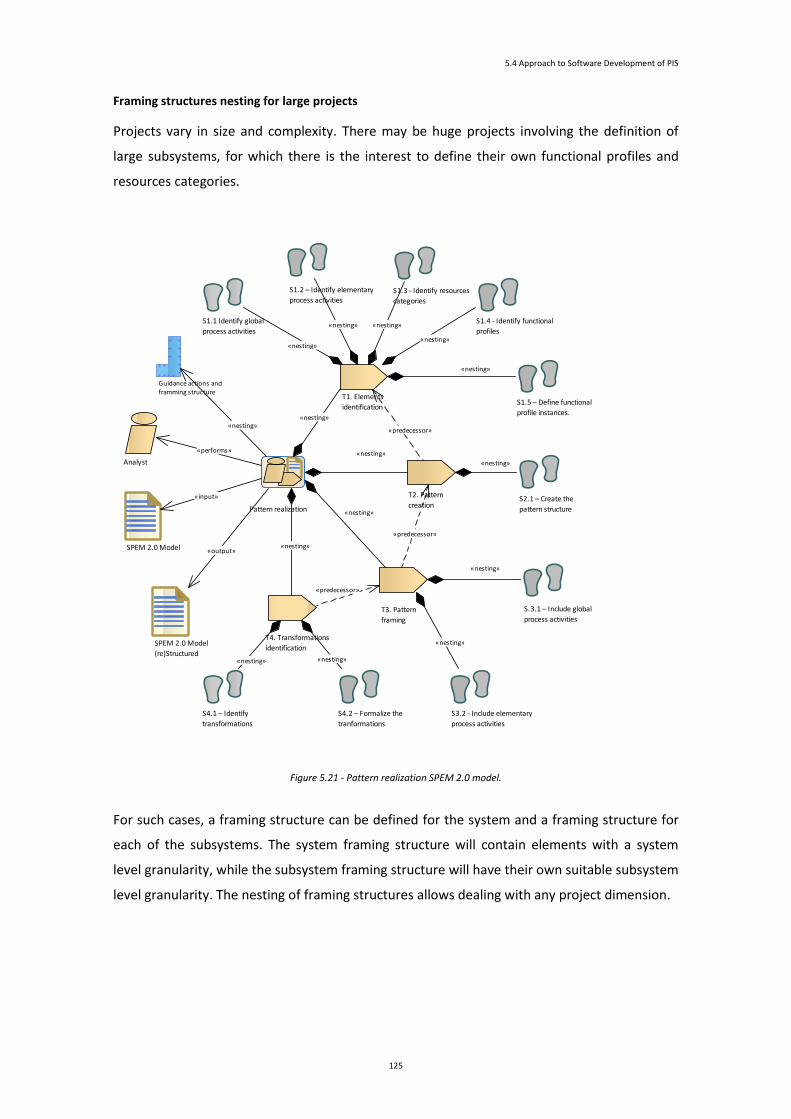
5.4 Approach to Software Development of PIS
125
Framing structures nesting for large projects
Projects vary in size and complexity. There may be huge projects involving the definition of
large subsystems, for which there is the interest to define their own functional profiles and
resources categories.
Figure 5.21 - Pattern realization SPEM 2.0 model.
For such cases, a framing structure can be defined for the system and a framing structure for
each of the subsystems. The system framing structure will contain elements with a system
level granularity, while the subsystem framing structure will have their own suitable subsystem
level granularity. The nesting of framing structures allows dealing with any project dimension.
Pattern realization
T1. Elements
identification
T2. Pattern
creation
T3. Pattern
framing
T4. Transformations
identification
S1.1 Identify global
process activities
S1.2 – Identify elementary
process activitiesS1.3 - Identify resources
categories
S1.4 - Identify functional
profiles
S1.5 – Define functional
profile instances.
S2.1 – Create the
pattern structure
S.3.1 – Include global
process activities
S3.2 - Include elementary
process activities
S4.1 – Identify
transformations
S4.2 – Formalize the
tranformations
Analyst
SPEM 2.0 Model
SPEM 2.0 Model
(re)Structured
Guidance actions and framming structure
«nesting»
«nesting»
«nesting»
«nesting»
«nesting»
«nesting»
«nesting»
«nesting»
«nesting»
«output»
«nesting»
«nesting»
«nesting»
«nesting» «nesting»
«performs»
«input»
«nesting»
«predecessor»
«predecessor»
«predecessor»

5 Approach to PIS Development
126
Figure 5.22 depicts the nesting of the framing structures to deal with the size of huge projects.
.
2B
1M
3B
5C
1A
2D
A B C D M
Category Category Category Category Category
Subsystem functional profile
Subsystem functional profile
Subsystem functional profile
Subsystem functional profile
Subsystem functional profile
1
2
3
4
5
nSubsystem functional profile
Global system high-level specification/model/artefact
...
Global system low-level specification/model/artefact
...
.
...
2B
1M
3B
5C
1A
2
A B C D MCategory Category Category Category Category
1
2
3
4
5
n
Global subsystem high-level specification/model/artefact
...
Global subsystem low-level specification/model/artefact
...
.
...
2
1M
3B
5C
1A
2D
A B C D MCategory Category Category Category Category
Functional profile
Functional profile
Functional profile
Functional profile
Functional profile
1
2
3
4
5
nFunctional profile
Global subsystem high-level specification/model/artefact
...
Global subsystem low-level specification/model/artefact
...
...
.
...
2B
1M
3B
5C
1A
2D
A B C D M
Category Category Category Category Category
1
2
3
4
5
n
Global subsystem high-level specification/model/artefact
...
Global subsystem low-level specification/model/artefact
...
.
2B
1M
3B
5C
1A
2D
A B C D M
Category Category Category Category Category
Functional profile
Functional profile
Functional profile
Functional profile
Functional profile
1
2
3
4
5
nFunctional profile
Global subsystem high-level specification/model/artefact
...
Global subsystem low-level specification/model/artefact
...
...
Figure 5.22 - Nesting of framing structures for huge projects.
Their deployment in the SPEM model can be achieve through proper realization of the
proposed development framework pattern for PIS for each of the framing structures,
independently of the part of the system they respect to. Each of the framing structures
implicitly defines its own namespace for its constituent elements.
Process’ elements level
At this level the attention is centred in the identification/definition of individual elements,
focusing on its structure or properties. The elements of major interest are those belonging to
the kind of work unit.
These kinds of elements are the ones that have the main contribution to an effective
deployment of a model-based approach, and that are on the crux of the matter of the
transition from qualifying an approach as model-based or model-driven development
approach (or in the middle of the two). These work unit elements define the inputs, outputs,
and task/steps that materialize the activity. The inputs are used as available, but in what
respects to the outputs produced, the activity can elaborate on its content, form, and quality.

5.4 Approach to Software Development of PIS
127
These outputs are the ones that made available and are posteriorly used as inputs in
succeeding activities.
The quality of the specification of the inner tasks/steps is of crucial relevance to the process
and may provide the grounding for a model-based “navigation” along the process. Among
quality properties of the activity specification are the activity elements and sequence
formalization, the precision, the clearness, and completeness.
SPEM 2.0 diagrams can be used as means to formalize and to assist in achieving/analysing
quality properties of activities. Figure 5.23 is an example of a SPEM 2.0 materialization of the
4SRS technique; it aims to produce an object system model representing the logical
architecture of the system, essentially based on an input use case model representing
functional requirements of the system.
Figure 5.23 - 4SRS model transformation technique under a SPEM 2.0 perspective.
From Use Cases to Objects: An Industrial IS Case Study Analysis
Functional Model
System Logical Architecture
Functional Model (from 4SRS)
Analyst
Optional task.
It is executed if :
(i) the functional model is not
expressed in a use case model form;
(ii) or the use case model have no
identifying tag values assigned to the
use cases.
"Each use case at the system-level is
assigned a tagged value (example:
ref=2), and if this use case is
eventually refined by other sub-use
cases, each one of these will have a
reference that uses the super-use
case as a prefix (example: ref=2.3).
This numbering scheme can be
repeated to any depth and is used to
ease the mapping from use cases to
objects."
«optional, output»
This output use case model has the
tagged values resulting from the
preparation step.
May be coincident with the input use
case model if this one already has the
tagged values.
«mandatory, input»
It is expected to be in a use case
model form.
Non-functionalrequirements
«optional, input»
«mandatory, output»
Use Case Model Preparation
1. Transform each use case into three objects
2. Choose survival objects
3.Create aggregations of semantically consistent survival objects
4. Link the aggregations to specify the associtions among existing objects
Associate non-functional requirements and design decisions to objects
«optional, output»
4SRS Model Transformation
«nesting»
«nesting» «predecessor»
«predecessor»
«predecessor»
«nesting»
«input»
«performs»
«nesting»
«output»
«input»
«predecessor»
«nesting»
«nesting»
«output»
«nesting»
«predecessor»

5 Approach to PIS Development
128
As it can be seen in the SPEM diagram depicted in Figure 5.23, 4SRS defines its inputs, outputs,
tasks of processing and roles, and provides a guidance to assist the technique implementation.
As far as possible and convenient, the activities in the process should then be described by a
SPEM 2.0 diagram in order to access or improve their quality, and properly distinguish from
the others.
5.5 Conclusion
This chapter presented an approach to software development of PIS based on model-
based/driven development concepts and techniques. It was introduced: (i) three dimensions of
system development that are relevant to the approach; (ii) a development framework to
support the approach; a SPEM Base Plug-In extension; (iii) a development framework pattern
for PIS; (iv) considerations relative to the framing of MDD concepts and techniques; and
supporting artefacts to the construction of PIS. It is expected that this approach suitably brings
the model-driven benefits to the development of pervasive information systems.
Some of the main concepts introduced in this chapter are summarized in Table 5.2.
Concepts Meaning
Category of resources Heterogeneous resources (e.g. computational devices) are grouped in category of resources
reflecting common basic resource and capabilities of the resources.
Development
structure
Different development structures for the different functional profiles of the category of devices
reflect pathways of software development in order to satisfy major categories of functionality.
Modelling levels For each of the development structures and transversal to all of the development structures, there
are several modelling levels.
At the top level, the platform-independent model (PIM) for each of class of devices is derived from
models resulted from development of the system as a whole.
At intermediate levels, there are PSM models.
At the bottom model level, there are the lower-level (Platform-Specific Models) PSMs from which the
final code is produced (either automatically generated or handcrafted).
Dimensions The approach for the development of PIS has three dimensions: resource, functional, and abstraction
dimensions.
The resource dimension focus on classification of resources in categories according to common
properties or capabilities of these resource.
The functional dimension focus on functional profiles specified for categories of resources.
The abstraction dimension focus on the abstraction modelling levels; these involve transformations
of models from higher-levels to low-levels of abstraction.

5.5 Conclusion
129
Concepts Meaning
Modelling levels Three modelling levels can be distinguished: high, intermediate, and bottom modelling levels.
The high modelling level. At this level, there is a PIM for each of category of resources. The PIM
derivates from models resulting from initial development of the system as a whole.
The intermediate modelling levels. At these levels, there are PSM models that can be either
associated to subcategories of resources or to design decisions that may somehow introduce a
certain degree of platform/technological dependence.
The bottom modelling level. At this level, there are the lowest-level PSMs from which the final code
will be produced (either automatically generated or handcrafted). From a PSM, it may be possible to
derive one or more different code artefacts due to platform differences where the code will be
deployed.
Global development
process
Global development effort is responsible for modelling requirements and for the establishment of
high-level global system’s models. From these, combinations of functional profiles and resources
categories are determined, and the high-level PIM for each combination needed on the system is
specified.
Elementary
development process
Individual development structures corresponding to the referred combinations, and are subject of its
own thread of development process referred as elementary development processes.
Types of model
mappings
Between models, two types of model mappings can be identified: vertical and horizontal model
mappings.
Vertical model mapping. Between the model levels, there are vertical model mappings, which being
based on well-established transformations, bring the abstract system’s models to a more concrete
and refined system model (nearer to technological aspects and to its final realization).
Horizontal model mappings. These mappings have the purpose to achieve, through specific
transformations, other goals than the one of a decrease of abstraction. For example, these horizontal
model mappings may exist in order to facilitate validation goals.
Table 5.2 - Main concepts of the proposed approach to the development PIS.


Chapter 6
Analysis of the Projects
Chapter Contents
6 Analysis of the Projects ........................................................................................................................ 133
6.1 Introduction .................................................................................................................................. 133
6.2 Analysis of uPAIN Project .............................................................................................................. 134
6.3 Analysis of USE-ME.GOV Project ................................................................................................... 144
6.4 Lessons Learned ............................................................................................................................ 160
6.5 Conclusion ..................................................................................................................................... 164

132

133
6
Analysis of the Projects
In this chapter, the projects of study in this thesis, projects uPAIN and USE-ME.GOV,
are revisited in order to be analysed. For each project, a pictorial description
illustrates generically illustrates the main activities and artefacts, a SPEM model
describes further detail the elements of the process development, and having in mind
the conceptions and structures introduced in chapter 5, it is performed analysis and
considerations about the project. The chapter then ends with reflections and
considerations considering both projects.
6.1 Introduction
Revisiting the projects presents an opportunity to observe them with attention focused on
particular items of interest in order to achieve the proper analysis. This analysis resorts to
SPEM 2.0 for building the diagrams that depict the structure of projects, making graphically
visible their main activities, artefacts, and relationships among them. Therefore, for each of
the projects, it was built a SPEM model of the project that is presented in this document.
Resorting to SPEM 2.0 for looking into the projects revealed, as it will be perceived, a proper
way to bring to light the understanding of the process internals.
Due to the size of project models and aiming to facilitate the presentation, the SPEM model
of each project is further divided and presented through diagrams related to specific main

Analysis of the Projects
134
phases/activities. Additionally, preceding and complementing the presentation of the SPEM
model, an auxiliary pictorial description is provided; it aims to ease the general understanding
of project activities and deliverables/artefacts.
The analysis use selective parts of the model (or diagrams) to stress points where issues are
verified or interventions are needed, or to make proper exemplifications. It is considered that
the use, where needed, of selective parts of the model instead of its totality, is proper and
sufficient for the presentation of the knowledge that the analysis intents to express, and does
not affect its precision or the proper expansion of the rationale for the whole project model.
To pursuit the goal of the analysis, it’s presented for each project: (i) the SPEM 2.0 model,
illustrating the main activities and artefacts; (ii) the framing structure as an auxiliary tool for
the identification of the functional profile instances; (iii) the application of the development
framework pattern, which allows to easier analysing an existing SPEM 2.0-based
development process its structure in the light of the approach conceptions; (iv) Reflection
and considerations about issues and facts of the project.
The remainder of this chapter is structured in three parts: (i) a first part related to analysis of
the uPAIN project; (ii) a second part related to analysis of USEME.GOV project; and (iii) a third
part in which is expressed and synthesized the knowledge that emerges for from these
project analysis.
6.2 Analysis of uPAIN Project
uPAIN grouped the activities by major concerns into five phases (as illustrated by Figure 6.1).
Project Management
Requirements Analysis and Elicitation
Research and Technological Development
Exploration and Evaluation of the Application
Medical Research
Figure 6.1 - Phases of uPAIN project.
In each of the phases, several activities were carried out that were designed to produce
several deliverables (SPEM diagrams, latter in this uPAIN section, will depict these activities).

6.2 Analysis of uPAIN Project
135
6.2.1 Pictorial Description of Major Activities and Deliverables
The deliverables designed to be produced in phases of “Project Management”, “Exploration
and Evaluation of the Application”, and “Medical Research”, are those illustrated by Figure
6.2.
Exploration and Evaluation of the Application
Refined specification of
the information system
Databases with information
from the protoype exploration
Report of usefulness, usability
and technology impact
Medical Research
Psycho-socio-cultural
surveys
Realized tests Pain assessment
Project Management
Periodic assessments of
project progress
Technical Meetings Project financial
management
Promotion and dissemination
of project results
Figure 6.2 - Major results in Project Management, Exploration and Evaluation of the Application, and Medical Research phases of
the uPAIN project.
These three phases don’t have the relevance for this study as the remaining others, as they
do not have activities that directly concerns to creation of artefacts that software
development of the system. As such, they are not subject of further analysis.
The phase of “Requirement Analysis and Elicitation” was designed to produce the
deliverables presented by Figure 6.3.
Figure 6.3 - Major results in Requirements Analysis and Elicitation phase of the uPAIN project.
Requirements Analysis and Elicitation phase is described (uPAIN, 2008) as having the tasks of
“Characterization of the environment”, “Elicitation and classification of user requirements”,
“Formalization of system requirements”, and “Refined planning”. These produce,
respectively, the deliverables “Problem Description”, User Requirements”, “System
Requirements” and “Refined Activities Plan”. The relationships between the phase, activities
and deliverables are better perceived through the SPEM diagram presented later.
Requirements Analysis and Elicitation
Problem Description User Requirements System Requirements Refined Activities Plan

Analysis of the Projects
136
The phase of “Research and Technological Development” was designed to produce the
deliverables presented by Figure 6.4.
Research and Technological Development
System Architecture comPCA Software for sPDAs Software for PSC Anesthesiology DB
Prototype # 1
(initial version)
Multimedia services Data mining techniques Prototype # 1 (completed
and corrected)
Prototype # 2
Figure 6.4 - Major results in Research and Technological Development phase of the uPAIN project.
Research and Technological Development phase is described (uPAIN, 2008) as including the
several tasks. Among these, it can be found the “Definition of architecture's solution”,
“Development of comPCA”, “Development of software for sPDAs pPDAs”, “Development of
software for the pSC”, “Development of anaesthesiology database”, “Technological
integration and prototype installation”, “AV Communications (streaming)”, “Development of
data mining techniques”, “Test and correction”, and “Extension for GSM / GPRS / UMTS”.
These tasks produce the deliverables illustrated by Figure 6.4.The relationships between the
phase, activities and deliverables are perceived better through the SPEM diagram presented
later.
6.2.2 SPEM 2.0-Based Description of Activities and Artefacts
The uPAIN project phases, main activities, tasks, artefacts, deliverables, and their
relationships are graphically visible through the SPEM model presented in Figure 6.5. In the
figure, the graphical elements are in a small dimension in order to one being able to see the
global picture; later illustrations will show, in visually comfortable diagrams, separated parts
of this model.
Among the several phases that constitute the project, “Requirements Analysis and
Elicitation”, and “Research and Technological Development” have greater dimension. They
are depicted with detail, as they are the ones of more interest in this study.
The rectangular shadow shape signals the tasks and artefacts that were not
explicitly/formally defined in the project.
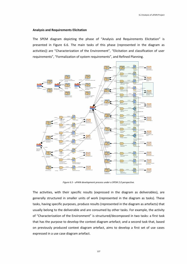
6.2 Analysis of uPAIN Project
137
Analysis and Requirements Elicitation
The SPEM diagram depicting the phase of “Analysis and Requirements Elicitation” is
presented in Figure 6.6. The main tasks of this phase (represented in the diagram as
activities)) are “Characterization of the Environment”, “Elicitation and classification of user
requirements”, “Formalization of system requirements”, and Refined Planning.
Figure 6.5 - uPAIN development process under a SPEM 2.0 perspective.
The activities, with their specific results (expressed in the diagram as deliverables), are
generally structured in smaller units of work (represented in the diagram as tasks). These
tasks, having specific purposes, produce results (represented in the diagram as artefacts) that
usually belong to the deliverable and are consumed by other tasks. For example, the activity
of “Characterization of the Environment” is structured/decomposed in two tasks: a first task
that has the purpose to develop the context diagram artefact; and a second task that, based
on previously produced context diagram artefact, aims to develop a first set of use cases
expressed in a use case diagram artefact.
Project Management
Management
Dissemination
Requirements Analysis and Elicitation
Characterization of the Environment
Elicitation and classification of user requirements
Formalization of system requirements
Refined Planning
Research and Technological Development
Definition of architecture's solution
Development of comPCA
Development of software for sPDAs pPDAs
Development of software for the pSC
Development of anesthesiology database
Technological integration and prototype installation
AV Communications (streaming)
Development of data mining techniques
Test and correction
Extension for GSM/GPRS/UMTS
Exploration and Evaluation of the Application
Characterization of the information system before the prototype
Exploration of the prototype
Evaluation of support offered by the system
Medical Research
Preparation of psycho-socio-cultural surveys
Execution of individual surveys to volunteers for test and improvement
Pain assessment in patients from HSO with uPAIN prototype
Context Diagram development
Use Case Diagrams development
Context Diagram
Use Case Diagrams [initial]
Problem Description
Use Case Diagrams development
Sequence Diagrams development
Use Case Diagrams [refined]
Sequence Diagrams
Petri lattices development CPNs
Refined activities plan
Components diagram
Executable prototype construction for requirements validation
Executable prototype for requirements validation
System architecture
System Requirements
Refined activities plan elaboration
Refined activities plan
Electrical and Electronic Project construction Electrical and
Electronic Project
Image processing software development Image processing software
comPCA
Software components development for sPDAs
Software components for pPDAs
Software components for sPDAs
Software components for pPDAs
Software for sPDAs and pPDAs
Software components development for PSC Software components
for PSC
Integration of sPC and SONHO DB Results from Integration with
SONHO DB
Software for PSC
Anesthesiology DB development
PHP application development
for surveys support
Anesthesiology DB
PHP application for surveys support
Anesthesiology DB
Technological
integraion
Prototype instalation
Prototype #1
Results from Prototype #1
installation
Prototype # 1 - initial version
Data mining techniquesData mining techniques development Data mining
techniques
Multimedia services development Multimedia services
Multimedia services
Testing and Correction
Prototype # 2Prototype # 2Expansion for
GSM/GPRS/UMTS
Prototype # 1 completed and corrected
Prototype # 1 completedand corrected
4SRS execution
User Requirements
«composition»
«nesting»
«nesting»
«nesting»
«nesting»
«predecessor»
«output»
«output»
«composition»
«composition»
«nesting»
«output»
«nesting»
«composition»
«predecessor»
«output»
«output»
«output»
«nesting»
«nesting»
«predecessor»
«composition»
«nesting»
«output»
«nesting»
«nesting»
«nesting»
«nesting»
«nesting»
«composition»
«composition»
«nesting»
«nesting»
«nesting»
«nesting»
«nesting»
«nesting»
«nesting»
«nesting»
«nesting»
«nesting»
«nesting»
«nesting»
«nesting»
«nesting»
«nesting»
«nesting»
«nesting»
«nesting»
«output»
«composition»
«output»
«composition»
«nesting»
«nesting» «output» «composition»
«nesting»
«output»
«composition»
«composition»
«composition»
«output»
«nesting»
«output»
«composition»
«input»
«input»
«input»
«input»
«input»
«nesting»
«output»
«output»
«output»
«composition»
«nesting»
«nesting»
«composition»
«output»
«input»
«composition»
«composition»
«composition»
«output»
«output»
«composition»
«composition»
«nesting»
«nesting»
«output»
«output»
«composition»
«nesting»
«nesting»
«input»
«nesting»

Analysis of the Projects
138
In this diagram, the project has made explicit only the phase, the activities, and the
deliverables. The tasks and artefacts were not made explicit, but were referenced during the
project development or implicit related to a work product realization. The rectangular
shadow shape signals these tasks and artefacts.
Figure 6.6 - SPEM 2.0 diagram of the phase “Requirements Analysis and Elicitation" of uPAIN project.
Research and Technological Development
The SPEM diagram depicting the phase of “Research and Technological Development” is split
(for legibility) into two parts that are shown respectively in Figure 6.7 and Figure 6.8. Figure
6.7 shows several activities that, based on results produced in preceding phase of
“Requirements Analysis and Elicitation”, conduct to the development of a first version of the
system prototype. The rectangular shadow shape signals the tasks and artefacts that were
not explicitly defined.
Requirements Analysis and Elicitation
Characterization of the Environment
Elicitation and classification of user requirements
Formalization of system requirements
Refined Planning
Context Diagram development
Use Case Diagrams development
Context Diagram
Use Case Diagrams [initial]
Problem Description
Use Case Diagrams development
Sequence Diagrams development
Use Case Diagrams [refined]
Sequence Diagrams
Petri lattices development CPNs
Refined activities plan
Executable prototype construction for requirements validation
Executable prototype for requirements validation
System Requirements
Refined activities plan elaboration
Refined activities plan
User Requirements
«output»
«predecessor»
«nesting»
«nesting»
«predecessor»
«output»
«output» «composition»
«output»
«composition»
«composition»
«predecessor»
«output»
«nesting»
«composition»
«nesting»
«nesting»
«nesting»
«composition»
«composition»
«nesting»
«nesting»
«nesting»
«nesting»
«nesting»
«composition»
«output»
«output»
«input»
«input»
«input»
«input»
«input»
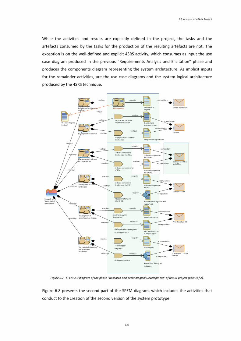
6.2 Analysis of uPAIN Project
139
While the activities and results are explicitly defined in the project, the tasks and the
artefacts consumed by the tasks for the production of the resulting artefacts are not. The
exception is on the well-defined and explicit 4SRS activity, which consumes as input the use
case diagram produced in the previous “Requirements Analysis and Elicitation” phase and
produces the components diagram representing the system architecture. As implicit inputs
for the remainder activities, are the use case diagrams and the system logical architecture
produced by the 4SRS technique.
Figure 6.7 - SPEM 2.0 diagram of the phase “Research and Technological Development" of uPAIN project (part 1of 2).
Figure 6.8 presents the second part of the SPEM diagram, which includes the activities that
conduct to the creation of the second version of the system prototype.
Research and Technological Development
Definition of architecture's solution
Development of comPCA
Development of software for sPDAs pPDAs
Development of software for the pSC
Development of anesthesiology database
Technological integration and prototype installation
Use Case Diagrams [refined]
Components diagram
System architecture
Electrical and Electronic Project construction Electrical and
Electronic Project
Image processing software development Image processing software
comPCA
Software components development for sPDAs
Software components for pPDAs
Software components for sPDAs
Software components for pPDAs
Software for sPDAs and pPDAs
Software components development for PSC Software components
for PSC
Integration of sPC and SONHO DB Results from Integration with
SONHO DB
Software for PSC
Anesthesiology DB development
PHP application development
for surveys support
Anesthesiology DB
PHP application for surveys support
Anesthesiology DB
Technological
integraion
Prototype instalation
Prototype #1
Results from Prototype #1
installation
Prototype # 1 - initial version
4SRS execution
«nesting»
«output»
«output»
«nesting»
«nesting»
«composition»
«nesting»
«nesting»
«nesting»
«nesting»
«nesting»
«nesting»
«output»
«composition»
«composition»
«output»
«composition»
«composition»
«output»
«composition»
«nesting»
«nesting»
«output»
«output»
«composition»
«nesting»
«nesting»
«composition»
«nesting»
«composition»
«nesting»
«output»
«output»
«composition»
«composition»
«nesting»
«nesting»
«output»
«output»
«input»

Analysis of the Projects
140
Regarding this second part of the model, the same considerations of the first part apply (the
tasks and artefacts that were not explicitly defined are signalled by the rectangular shadow
shape).
Figure 6.8 - SPEM 2.0 diagram of the phase “Research and Technological Development" of uPAIN project (part 2of 2).
Project Management, Exploitation and Application Evaluation, and Medical Research
These phases are herein presented (Figure 6.9) are deemed to be not relevant for the focus
of this work and thus are not further analysed. They are presented here only in order to allow
a better legibility of the several parts of the SPEM model of the project.
Figure 6.9 - SPEM 2.0 diagram of the phases “Project Management”, “Exploitation and Application Evaluation”, and “Medical
Research” of uPAIN project.
Research and Technological Development
AV Communications (streaming)
Development of data mining techniques
Test and correction
Extension for GSM/GPRS/UMTS
Data mining techniquesData mining techniques development Data mining
techniques
Multimedia services development Multimedia services
Multimedia services
Testing and Correction
Prototype # 2Prototype # 2Expansion for
GSM/GPRS/UMTS
Prototype # 1 completed and corrected
Prototype # 1 completedand corrected
«nesting»
«nesting»
«nesting»
«composition»
«nesting»
«output»
«nesting»
«nesting»
«composition»
«output»
«composition»
«nesting»
«output»
«nesting»
«composition»
Project Management
Management
Dissemination
Exploration and Evaluation of the Application
Characterization of the information system before the prototype
Exploration of the prototype
Evaluation of support offered by the system
Medical Research
Preparation of psycho-socio-cultural surveys
Execution of individual surveys to volunteers for test and improvement
Pain assessment in patients from HSO with uPAIN prototype
«nesting»
«nesting»
«nesting»
«nesting»
«nesting»
«nesting»
«nesting»
«nesting»

6.2 Analysis of uPAIN Project
141
6.2.3 Development Framework Pattern
Attending to the projects dimension and for the purposes of this perspective, in either its
structural level or its process’ elements level and where suitable, only a part of the model will
be used for illustration purposes (this does not affect the rationale to be taken for the whole
model).
Figure 6.10 illustrates the framing structure for uPAIN project. It shows the functional profile
instances that get existence in the project.
A B C D
1A
4C
6D
2B 2D
ComPCA PDA Server Desktop
ComPCA
Staff
Patient
pSC
Anesthesiology DB
System architecture
3B
5C
Requirements specification
Prototype #2
Prototype #1
1
2
3
4
5
6
FP – Functional Profile1A – ComPCA FP2B – sPDA FP2D – staff desktop
3B – pPDA FP4C – pSC FP5C – Anesthesiology DB6D – Survey’s support application
Survey’s support application
Figure 6.10 - Framing structure for uPAIN project.
The realization of the PIS development framework pattern had as input, the SPEM model
previously defined for the uPAIN project and this framing structure. Figure 6.11 and Figure
6.12 present the diagrams that illustrate the main results. The remainder SPEM model is not
presented; nonetheless, it follows a light and coherent rearrangement reflecting the
restructuration meanwhile realized.
Figure 6.11 highlight the results of performing Tasks T1, T2, and T3, excepting the step S3.2
(“Include elementary process activities”) that is later presented in Figure 6.12. As it can be
seen in Figure 6.11, between the «GlobalProcess» instance “uPAIN” and the
«FrameworkSupport» “Framework Creation”, it was interspersed the “Research and
Technological Development” activity instance.
The resources categories, functional profiles, and functional profiles instances are in
conformity with the framing structure presented in Figure 6.10.

Analysis of the Projects
142
The structure of the pattern is easily recognized, since it follows an identical disposition. It
can be noted that, relatively the original SPEM diagram of the project, some
precision/completeness deemed of interest is introduced, either in functional profiles
(through “Survey’s support app) or in the elementary processes (through distinction between
“2B - sPDA” and ”3B-pPDA).
Figure 6.11 – uPAIN’s restructured SPEM diagram (major structuring elements).
Figure 6.12 highlight the results from performing step S3.2 (“Include elementary process
activities”) of task T3, and the steps of task T4. For each of the elementary processes, it was
included the corresponding activity previously identified in step S1.2 (“Identify elementary
process elements”); for those that were not explicitly identified an activity, it was defined one
with a consistent name, which is to be appropriately accommodated with the remainder
elements in the SPEM diagram.
Research and Technological Development
«FrameworkSuppo...
Framework Creation
«FrameworkSupport»
Functional Profiles Definition
«FrameworkSupport»
FP Instances Definition
«FrameworkSupport»
Elementary Processes Creation
«FrameworkSupport»
Resources Categories Definition
«GlobalProcess»uPAIN
«ResourceCategory»
comPCA
«ResourceCategory»
PDAs
«ResourceCategory»
Server
«ResourceCategory»
Desktop
«FunctionalProfile»
ComPCA
Resource Categories Functional Profiles
«FunctionalProfile»
Staff
«FunctionalProfile»
Patient
«FunctionalProfile»
pSC
Functional Profile Instances
«FunctionalProfile»
Anesthesiology DB
«FunctionalProfile»
Survey' supporting app
«FP_Instance»
1A - ComPCA
«FP_Instance»
2B - sPDA
«FP_Instance»
3B - pPDA
«FP_Instance»
4C - pSC
«FP_Instance»
5C - Anesthesiology DB
«FP_Instance»
2D - staff Desktop
«FP_Instance»
6D - Survey's supporting app
«ElementaryProcess»
1A - ComPCA
«ElementaryProcess»
2B - sPDA
«ElementaryProcess»
3B - pPDA
«ElementaryProcess»
4C - pSC
«ElementaryProcess»
5C - Anesthesiology DB
«ElementaryProcess»
2D - staff Desktop
«ElementaryProcess»
6D - Survey's supporting app
Requirements Analysis and Elicitation
Project Management
Medical Research
Exploration and Evaluation of the Application
«nesting»
«composition»
«composition»
«composition»
«output» «output»
«composition»
«composition»
«composition»
«nesting»
«composition»
«output»
«nesting»
«nesting»
«nesting» «nesting»
«nesting»
«nesting»
«nesting»
«nesting»
«composition»
«composition»
«nesting»
«nesting»
«nesting»
«nesting»
«nesting»
«nesting»
«composition»
«composition»
«composition»
«composition»
«input» «input»
«input»
«composition» «composition»
«composition»
«nesting»
«composition»

6.2 Analysis of uPAIN Project
143
Figure 6.12 also highlight the identification of a transformation corresponding to the 4SRS
technique; this transformation was previously formalized, and as such, is not here again
further detailed.
Some short notes about the uPAIN project’s development process: (i) uPAIN’s designated
phases should be designated as activities (phases as connotation to time, and activities are
connoted to doing work; for example, for project management it is more suitable the
classification as an activity than as a phase); (ii) It should be clearly made distinct the
objectives and the results (in the template definition of the project, objectives and results are
mixed together); (iii) It should be defined separated tasks (and not to be implicitly the
objectives/results) for each developed artefact (such as a task for sPDAs and another for
pPDAs); (iv) It should also be explicit stated as tasks implicit artefacts development (such as
the Survey’s supporting application). The inclusion of the development framework pattern
was simple; it did not pose any special difficulty.
Figure 6.12 - uPAIN’s restructured SPEM diagram (transformations and elementary process activities).
Requirements Analysis and Elicitation
Characterization of the Environment
Elicitation and classification of user requirements
Formalization of system requirements
Refined Planning
Research and TechnologicalDevelopment
Definition of architecture's solution
Development of comPCA
Development of software for sPDAs
Development of software for the pSC
Development of anesthesiology database
Technological integration and prototype installation
AV Communications (streaming)
Development of data mining techniques
Test and correctionExtension for GSM/GPRS/UMTS
Use Case Diagrams[refined]
Components diagram
System architecture
«FrameworkSupport»Framework Creation
«FrameworkSupport»Elementary Processes Creation
«GlobalProcess»uPAIN
«ModelTransformation»
4SRS application
«ElementaryProcess»
1A - ComPCA
«ElementaryProcess»
2B - sPDA
«ElementaryProcess»
3B - pPDA
«ElementaryProcess»
4C - pSC
«ElementaryProcess»
5C - Anesthesiology DB
«ElementaryProcess»
2D - staff Desktop
«ElementaryProcess»
6D - Survey's supporting app
Development of software for pPDAs
Development of Survey's supporting application
Development of staff Desktop
«nesting»
«nesting»
«nesting» «output»
«nesting» «nesting»
«nesting»
«nesting»
«nesting»
«input»
«nesting»
«nesting»
«nesting»
«nesting»
«nesting»
«nesting»
«nesting»
«nesting»
«nesting»
«nesting»
«nesting»
«nesting»
«composition»
«nesting»
«nesting»
«nesting»
«nesting»
«nesting»
«nesting»
«nesting»
«nesting»
«nesting»

Analysis of the Projects
144
6.3 Analysis of USE-ME.GOV Project
USE-ME.GOV project established several efforts for the development of the system. The most
relevant of these from the point of view of this study are: (i) an initial work to clarify
requirements and settle the logical architecture of the system; (ii) development of the core
platform subsystem; (iii) development of repository services; (iv) development of the four
target pilot services, namely, the “Healthcare” service, the “Mobile Student” service, the
“Report of Complaint” service, and the “City Information” service. Figure 6.13 illustrates
these development efforts.
Project Management
Service Scenario Definitions and Evaluation
Preliminary Design and Mock-Up
Requirements Analysis
Detailed Design Specifications
Implementation and Integration
Validation
Recommendations
Figure 6.13 - USE-ME.GOV major development efforts.
6.3.1 Pictorial Description of Major Activities and Deliverables
The deliverables designed to be produced in the phases of “Project Management”,
“Validation”, and “Recommendations”, are those illustrated by Figure 6.14.
Validation
Validation Plan Validation Review
Report
Recommendations
...for “Business
Planning”
...for “Implementation
Planning”
...for “Standardizations
and Regulations”
Platform Requirements
Analysis
Project Management
Quality Assurance Plan
Figure 6.14 - Deliverables in Implementation and Integration, in Validation, and in Recommendations.

6.3 Analysis of USE-ME.GOV Project
145
These three phases do not have the relevance to this study as the remaining others, as they
do not have activities that directly concerns to creation of development artefacts of the
system. As such, they are not subject of further analysis.
The phase of “Service Scenario Definitions and Evaluation” was designed to produce the
deliverables presented by Figure 6.15.
Service Scenario Definitions and Evaluation
User Requirements Analysis Review of Available Business
Models
Review of state of art for Intuitive
and Mobile Interface DesignReview of state of art for Platform
Architecture and General Design
Service Use and Scenario Defintion
...for “Broadcasting of Critical
Information”
...for “Reports and Complaints”...for “The Mobile Student” ...for “Local Event Promotion”...for “Health Care Information”
Technical Implementation
Requirements
Figure 6.15 - Deliverables for Service Scenario Definitions and Evaluation.
The phase of “Requirements Analysis” was designed to produce the deliverables presented
by Figure 6.16.
Requirements AnalysisPlatform Requirements
Analysis
Usability Requirements Analysis
...for “Broadcasting of
Critical Information”
...for “Reports and
Complaints”
...for “The Mobile
Student”
...for “Health Care
Information”
Pilot Service Requirements Specifications
...for “Broadcasting of
Critical Information”
...for “Reports and
Complaints”
...for “The Mobile
Student”
...for “Health Care
Information”
Figure 6.16- Deliverables in Requirements Analysis.
The phase of “Preliminary Design and Mock-Up Evaluation” was designed to produce the
deliverables presented by Figure 6.17.
Preliminary Design & Mock-Up
Platform Preliminary Design
and Mock-up Evaluation
Usability-Driven and Mock-Up Evaluation
...for “Broadcasting of
Critical Information”
...for “Reports and
Complaints”
...for “The Mobile
Student”
...for “Health Care
Information”
Figure 6.17 – Deliverables in Preliminary Design and Mock-up.

Analysis of the Projects
146
The phase of “Detailed Design and Specification” was designed to produce the deliverables
presented by Figure 6.18.
Detailed Design and Specification
Platform and Application Detailed Design
Core Platform ...for “Reports and
Complaints”
Service Repository ...for “Health Care
Information”
...for “Broadcasting of
Critical Information”
Managment Console...for “The Mobile
Student”
Platform Services External Data
Sources
Pilot Services Detailed Services Specifciation
...for “Broadcasting of
Critical Information”
...for “Reports and
Complaints”
...for “The Mobile
Student”
...for “Health Care
Information”
Figure 6.18 - Deliverables in Detailed Design and Specification.
The phase of “Implementation and Integration” was designed to produce the deliverables
presented by Figure 6.19.
Implementation and Integration
Integration and Test plan Integration and Test Report
Figure 6.19 - Deliverables in Implementation and Integration.
6.3.2 SPEM 2.0-Based Description of Activities and Artefacts
The USE-ME.GOV project’s phases, main activities, tasks, artefacts, deliverables, and their
relationships are graphically visible through the SPEM model presented in Figure 6.20. In the
figure, the graphical elements are in a small dimension in order to one being able to see the
global picture; later illustrations will show, in visually comfortable diagrams, separated parts
of this model.
The rectangular shadow shape signals the tasks and artefacts that were not
explicitly/formally defined in the project.
The project references the consumption/production at deliverable level and uses coarse work
units, which is reflected in the SPEM model (artefacts are they are usually part of some
deliverable and tasks are part of the structure of some activity).

6.3 Analysis of USE-ME.GOV Project
147
Where appropriate in this document, segments of the SPEM diagram are shown with those
modelling artefacts and associated tasks.
Figure 6.20- USE-ME.GOV development process under a SPEM 2.0 perspective.
Technical Implementation Requirements
User Requirements
Review of Available Business Models
Review of State of the Art for Intuitive and Mobile Interface Design
Review of State ot the Art for Platform Architecture and General Design
Service Use and Scenario Definition
Usability Requirements Analysis
Platform Requirements Analysis
Requirements Analysis
Service Scenario Definition and Evaluation
Requirements Review
Usability-Driven and Mock-Up Evaluation
Platform Architecture Design Mock-Up
Preliminary Design & Mock-Up
Components Functional Design
Distributed Sharing of Content
User Authentication and Security
Components Functional Design
Distributing Sharing ofContent
User Authentication and Security
Detailed Design and Specification
Requirements Revision
Core Platform Specification
Detailed Components Interf. andAppl. Specification
Service Repository Specification
Platform Services
Pilot Services
Management Console
External Data Sources
Pilot Services
External Data Sources
Platform Functional Design (implicit research task)
Core Platform
Service Repository
Management Console
Platform Services
Pilot Services
Meta Protocol of Services Design
Service Models Business Definition
Service Application IntegrationSpecification
Components Development
Service Applications Development
Components Development Results
Service Applications Development Results
Integration and Test Plan Definition
Integration and Testing
Pilot Services Installation
Pilot Services Operation
Validation Plan Definition
Validation
Validation Review
Working System
Project Coordination
Project Assessment
Consortium Agreement
Consortium Agreement - Annex I - Description of Work
Project Kick-off
Business Planning
Implementation Planning
Standardization and Regulations
Business Planning
Implementation Planning
Standardization and Regulations
Recommendations
User Requirements Analysis
Quality Assurance Plan
Assessment and Evaluation ReportReview of Available Business
Models
Review of State of the Art in User Interface design for Mobile Applications
Open Platform for Mobile Services – State of the Art
Tecnhical Implementation Requirements
Service and Use Scenario Definition
Usability Requirements Definition for Selected Scenarios
Plataform Requirements Analysis
Pilot Services Requirements Specifications
Usability-Driven and Mock-Up Evaluation
Platform Preliminary Design and Mock-Up Evaluation
Platform Architecture Design
Platform Functional Design
Meta Ptotocol of Service Types
Service Business Model Definition
Pilot Services Detailed Services Specification
Platform and Application Detailed Design
Platform Components and Applications
Integration and Testplan
Software Product
Validation Plan
Validation Review Report
Integration and Test Report
Results from Service Application Integration Specification
Pilot Services Specification
Platfrom Functional Design
Project Kick-Off
Quality assurance plan
Service and Use ScenarioEvaluation
Usability Requirements Definition
Preliminary Interface Design and Mock-Up Evaluation
Protoype Implementation and Validation
Interface Intuitive Design for Mobile Services in Public Administration
Interface Design Evaluation
Platfom Requirements Definition
Platform Architecture Design and Mock-Up
Meta-Protocol and Preliminary Funct.Design
Platform and Application Detailed Design
Platform Components and Service Applications
Final Recommendations
Implementation and Integration
Validation
Validation plan
Validation review and results
Integration and test plan
Final Integration
Results ffrom Pilot Services Installation
Dissemination and Exploitation Planning
Dissemination and Prelim. Explotation Plan
Dissemination and Prelim. Exploitation Plan
Dissemination Activities and Events
Dissemination Review
Dissemination Plan Definition
Dissemination review reportDissemination Review, Exploit. Plan
Compliation of Plaform and Application Detailed Design contributions
Compilation of Platform Architecture Design contributions
Recommendations Elaboration
«composition»
«output»
«composition»
«nesting»
«nesting»
«composition»
«composition»
«composition»
«composition»
«composition»
«output»
«output»
«input»
«output»
«required results»
«output»
«output»
«output»
«output»
«composition»
«input»
«composition»
«required results»
«required results»
«input»
«output»
«input»
«input»
«input»
«input»
«nesting»
«input»
«input»
«composition»
«composition»
«composition»
«output»
«composition»
«composition»
«input»
«input»
«input»
«output»
«nesting»
«output»
«input»
«nesting»
«composition»
«composition»
«input»
«output»
«input»
«nesting»
«output»
«output»
«output»
«output»
«output»
«output»
«input»
«output»
«predecessor»
«composition»
«nesting»
«input»
«input»
«nesting»
«input»
«nesting»
«input»
«input»
«output»
«nesting»
«nesting»
«nesting»
«nesting»
«nesting»
«nesting»
«nesting»
«composition»
«input»
«nesting»
«nesting»
«nesting»
«nesting»
«nesting»
«nesting»
«nesting»
«nesting»
«required results»
«nesting»
«required results»
«nesting»
«nesting»
«nesting»
«required results»
«required results»
«required results»
«required results»
«output»
«nesting»
«nesting»
«nesting»
«nesting»
«input»
«composition»
«composition»
«required results»
«required results» «output»
«required results»
«nesting»
«required results»
«nesting»
«output» «required results»
«required results»
«required results»
«required results»
«output»
«output»
«predecessor»
«output»
«output»
«input»
«output»
«input»
«input»
«output»
«input»
«required results»
«output»
«input»
«predecessor»
«predecessor»
«predecessor»
«input»
«input»
«required results»
«predecessor»
«nesting»
«output»
«composition»
«nesting»
«required results»
«required results»
«required results»
«required results»
«required results»
«required results»
«input»
«output»
«composition»
«output»
«output»
«composition»
«output»
«output»
«output»
«input»
«input»
«output»
«input»

Analysis of the Projects
148
Scenario Definition and Evaluation
Figure 6.21 illustrates the main activities, deliverables and other outcomes related to
“Scenario Definition and Evaluation Activity” (mentioned as ‘work package’ in the project). It
had as milestone the production of service scenarios for each of the pilot services of the
project.
Figure 6.21 - SPEM 2.0 perspective over Service Scenario Definitions and Evaluation in USE-ME.GOV.
To achieve such milestone, several activities were performed, from gathering user
requirements (from the public authorities’ perspective), reviewing state-of-the-art, to
defining technical implementation requirements.
“Technical Implementation Requirements” established, among other technical definitions, a
first schema for the platform architecture and for the added-value service architecture.
“Service Use and Scenario Definition” elaborated, for each target service, an initial use case
model enriched with activity diagrams.
Schema for Platform Architecture
Technical Implementation Requirements
User Requirements
Review of Available Business Models
Review of State of the Art for Intuitive and Mobile Interface Design
Review of State ot the Art for Platform Architecture and General Design
Service Use and ScenarioDefinition
Service Scenario Definition and Evaluation
User Requirements Analysis
Review of Available Business Models
Review of State of the Art in User Interface design for Mobile Applications
Open Platform for Mobile Services – State of the Art
Tecnhical Implementation Requirements
Service and Use Scenario Definition
Service and Use ScenarioEvaluation
Use case model (complemented with activity diagrams) for each target service
Schema for Added Value Service Architecture
«nesting»
«output»
«output»
«output»
«output»
«nesting»
«input»
«input»
«input»
«output»
«output»
«composition»
«nesting»
«nesting»
«nesting»
«nesting»
«input»
«required results»
«composition»
«composition»
«input»

6.3 Analysis of USE-ME.GOV Project
149
Requirements Analysis
Figure 6.22 illustrates the main activities, deliverables, and other outcomes from
“Requirements Analysis”. All the activities had the “Service and Use Scenario Definition”
deliverable as input artefact. A relevant activity, included in “Platform Requirements
Analysis”, is the model transformation technique called “4SRS”, which formalizes the passage
from use cases models to an object model representing the logical system architecture.
Figure 6.22 - SPEM 2.0 perspective over Requirements Analysis in USE-ME.GOV.
“Requirements Review” was the name of the activity that produced the “Pilot Services
Requirements Specifications” deliverable, which defined the requirements specification for
the each of the target pilot services (this specification was latter used for detailed service
specifications). In this activity, service scenarios were defined for each service (sequence
diagrams were used); additionally, a list of functional requirements were specified for each
service.
Preliminary Design & Mock-Up
Preliminary Design & Mock-Up activities had the purpose of anticipating design decisions.
Some mock-ups evaluations of user interfaces for each of the pilot services were performed.
Mock-ups were also elaborated for the system and some modelling artefacts were produced,
Usability Requirements Analysis
Platform Requirements Analysis
Requirements Analysis
Requirements Review
Service and Use Scenario Definition
Usability Requirements Definition for Selected Scenarios
Plataform Requirements Analysis
Pilot Services Requirements Specifications
Usability Requirements Definition
Platfom Requirements Definition
4SRS High-level object/components of the system
«input»
«input»
«output»
«output»
«nesting»
«nesting»
«input»
«input»
«nesting»
«nesting»
«required results»
«required results»
«input» «output»
«composition»
«output»

Analysis of the Projects
150
such as the high-level system diagram or the core platform layers view. Class diagrams and
sequence diagrams are among typical UML diagrams used.
Figure 6.23 illustrates the main activities, deliverables and other outcomes related to
Preliminary Design and Mock-Up.
Figure 6.23 - SPEM 2.0 perspective over Preliminary Design and Mock-Up in USE-ME.GOV.
Detailed Design and Specification
The “Detailed Design and Specification” activities further detail the preliminary design. “Pilot
Services Detailed Design” details the design for the selected pilot services. This design appear
again detailed by the activity of “Platform and Application Design”, which also details the
design for the core platform, service repository, management console, and external data
sources.
Other important activities were carried: the “Meta-Protocol of Services Design”, which aimed
to constitute a framework for meaningful communication among platform components; the
“Platform Functional Design”, being a research task, described research findings and
Usability-Driven and Mock-Up Evaluation
Platform Architecture Design Mock-Up
Preliminary Design & Mock-Up
Core Platform
Service Repository
Management Console
Platform Services
Pilot Services
Service and Use Scenario Definition
Usability Requirements Definition for Selected Scenarios
Plataform RequirementsAnalysis
Pilot Services Requirements Specifications
Usability-Driven and Mock-Up Evaluation
Platform Preliminary Design and Mock-Up Evaluation
Platform Architecture Design
Preliminary Interface Design and Mock-Up Evaluation
Protoype Implementation and Validation
Interface Intuitive Design for Mobile Services in Public Administration
Interface Design Evaluation
Platform Architecture Design and Mock-Up
Compilation of Platform Architecture Design contributions
Pilot services mock-ups
«composition»
«output»
«nesting»
«input» «input» «input»
«nesting»
«output»
«composition»
«output»
«composition»
«input»
«composition»
«input»
«required results»
«required results»
«nesting»
«output»
«required results»
«required results»
«composition»
«composition»
«composition»

6.3 Analysis of USE-ME.GOV Project
151
decisions taken. Figure 6.24 illustrates the main activities, deliverables, and other outcomes
related to “Detailed Design and Specification” activities.
Figure 6.24 - SPEM 2.0 perspective over Detailed Design and Specification in USE-ME.GOV.
Implementation and Integration
“Implementation and Integration” activities had the purpose of realizing the models into
tangible application components and of integrating them into a working system. Testing and
Components Functional Design
Distributed Sharing of Content
User Authentication and Security
Components Functional Design
Distributing Sharing ofContent
User Authentication and Security
Detailed Design and Specification
Pilot Services Detailed Services Specification
Core Platform Specification
Detailed Components Interf. andAppl. Specification
Service Repository Specification
Platform Services
Pilot Services
Management Console
External Data Sources
Pilot Services
External Data Sources
Platform Functional Design (implicit research task)
Meta Protocol of Services Design
Tecnhical Implementation Requirements
Pilot Services RequirementsSpecifications
Usability-Driven and Mock-Up EvaluationPlatform Architecture
Design
Platform Functional Design
Meta Ptotocol of Service Types
Pilot Services Detailed Services Specification
Platform and Application Detailed Design
Platfrom Functional Design
Meta-Protocol and Preliminary Funct.Design
Platform and Application Detailed Design
Compliation of Plaform and Application Detailed Design contributions
«output»
«output»
«output»
«nesting»
«nesting»
«nesting»
«nesting»
«nesting»
«nesting»
«nesting»
«input» «input»
«input»
«input»
«input»
«input»
«input»
«composition»
«composition»
«composition»
«output»
«input»
«output»
«composition»
«input» «composition»
«output»
«required results»
«required results»
«required results»
«composition»
«composition»
«composition»
«composition»
«composition»
«composition»
«composition»

Analysis of the Projects
152
installation were also included activities. Figure 6.25 illustrates the main activities,
deliverables, and other outcomes related to “Detailed Design and Specification” activities.
Figure 6.25 - SPEM 2.0 perspective over Implementation and Integration in USE-ME.GOV.
Service Models Business Definition
Service Application IntegrationSpecification
Components Development
Service Applications Development
Components Development Results
Service Applications Development Results
Integration and Test Plan Definition
Integration and Testing
Pilot Services Installation
Pilot Services Operation
Working System
Platform Preliminary Design and Mock-Up Evaluation
Service Business Model Definition
Platform and Application Detailed Design
Platform Components and Applications
Integration and Testplan
Software Product
Integration and Test Report
Results from Service Application Integration Specification
Pilot Services Specification
Platform Components and Service Applications
Implementation and Integration
Integration and test plan
Final Integration
Results ffrom Pilot Services Installation
«composition»
«composition»
«predecessor»
«input» «input»
«predecessor»
«predecessor»
«output»
«output» «input»
«required results»
«output»
«required results»
«output»
«output»
«input»
«output»
«nesting»
«required results»
«required results»
«output»
«required results»
«nesting»
«nesting»
«output»
«nesting»
«required results»
«nesting»
«nesting»
«nesting»
«required results»
«output»
«input»
«nesting»

6.3 Analysis of USE-ME.GOV Project
153
Validation, Project Planning, Recommendations, and Dissemination
The activities in “Validation”, “Project Planning”, “Recommendations”, and “Dissemination”,
illustrated by Figure 6.26 and Figure 6.27, are deemed not relevant for the focus of this work.
Figure 6.26 - SPEM 2.0 perspective over Validation in USE-ME.GOV.
Figure 6.27 - SPEM 2.0 perspective over Project Planning, Recommendations, and Dissemination in USE-ME.GOV.
Validation Plan Definition
Validation
Validation Review
Working System
Quality Assurance Plan Plataform Requirements Analysis
Validation Plan
Validation Review Report
Validation
Validation plan
Validation review and results
User Requirements Analysis
«required results»
«required results»
«nesting»
«nesting»
«nesting»
«input» «input» «input»
«input»
«output»
«input»
«output»
«predecessor»
«predecessor»
Project Coordination
Project Assessment
Consortium Agreement
Consortium Agreement - Annex I - Description of Work
Project Kick-off
Business Planning
Implementation Planning
Standardization and Regulations
Business Planning
Implementation Planning
Standardization and Regulations
Recommendations
Quality Assurance Plan
Assessment and Evaluation Report
Project Kick-Off
Quality assurance plan
Final Recommendations
Dissemination and Exploitation Planning
Dissemination and Prelim. Explotation Plan
Dissemination and Prelim. Exploitation Plan
Dissemination Activities and Events
Dissemination Review
Dissemination Plan Definition
Dissemination review reportDissemination Review, Exploit. Plan
«required results»
«output»
«output»
«output»
«input»
«output»
«output»
«output»
«composition»
«output»
«required results»
«composition»
«required results»
«required results»
«required results» «output»
«nesting»
«nesting»
«nesting» «predecessor»
«output» «required results»
«composition»
Analysis of the Projects
154
6.3.3 Development Framework Pattern
Taking into account the projects dimension and the purposes of this perspective in either its
structural level or its process’ elements level, only a part of the model (where appropriate)
will be used for illustration purposes (this does not affect the rationale to be taken for the
whole model).
The USE-ME.GOV project is extensive and includes several subsystems services. In the light of
the approach proposed, these subsystems can be seen as a system for which a whole
development process can be applied. As such, the analysis/restructuration of this project will
have certain nuances from the analysis performed for the previous project. It will have a
context framing structure identifying the major subsystem’s functional profile and
subsystem’s resource category groupings. Then, for each of the subsystems functional profile
instance (the crossing of subsystem’s functional profile with subsystems’ resources category
grouping) is developed a new framing structure. This framing structure will consider as the
high-level models the ones regarding to the specific subsystem’s functional profile instance.
For each subsystem’s functional profile instance, there will be their functional profiles and
resources categories, as expected (unless there is another level of subsystems, in which case,
the rationale is applied again). This last framing structure is similar to what was conceived for
previous project.
The USE-ME.GOV SPEM diagram from USE-ME.GOV project assisted in the definition of
several framing structures. The following paragraphs show the context framing structure of
USE-ME.GOV and the redefinition of the SPEM diagram to reflect the pattern realization at
this contextual level. For one of the identified subsystem’s functional profile instances, the
respective nested framing structure is illustrated. Further nested framing structures of this
last one will not be presented here, once that the rationale behind is analogous to the one
performed for previous project, where no subsystems were included.
Figure 6.28 illustrates the framing structure for the system level. It shows the subsystem’s
functional profile instances that get existence in the project. The global process
models/artefacts designated as “Requirements specification” include the results from
project’s SPEM activities of “Service Scenario Definition and Evaluation” and the results from
“Requirements Analysis” (with the exception of the results from “Platform Requirements
Analysis” which is included in the global process activity “Platform Architecture”). The global
process artefacts/products “Integrated System” and “Final Executable System” are not clearly
explicit from the SPEM model. The figure represents them because the finalization of the
development process implicitly involves them.

6.3 Analysis of USE-ME.GOV Project
155
The framing structure has two major subsystems’ functional profiles: “Platform” and “Pilot
Services”. The resources categories related to subsystem functional profiles (as it also
happens at the system level), have symbolic names of “Category group A”, “Category group
B”, and so on. In these cases, it is acceptable to make no explicit
identification/characterization of the resources categories. The framing structure assigns
each of the subsystem functional profiles to only one18 resource group, giving origin to a
single subsystem functional profile.
2B
1A
A B
Category group
1
2
3
Requirements specification
...System architecture
Integrated system
Final executable system
Platform
Pilot Services
Category group
Figure 6.28 - Framing structure at system level for USE-ME.GOV project.
The “Platform” functional profile instance has also a corresponding framing structure. Figure
6.29 shows the faming structure for Platform functional profile instance. The figure shows
that the Platform subsystem (corresponding to the previous functional profile instance) has
its own functional profiles “Core Platform”, “Service Repository”, “Platform Services”,
“Management Console”, and “External Data Sources”.
.
2B
3C
5E
1A
A B C D E
Category group
1
2
3
4
5
1A - Functional profile instance for Platform subsystem
...
Core platform
Service repository
Platform services
Management console
External data sources
Category group Category group Category group Category group
4D
Figure 6.29 - Functional profile instance for Platform subsystem.
18 The absence of resource group characterization and the reasonable assumption that a subsystem needs only one supporting resource category group gives origin to a single resource category group for a subsystem functional profile.

Analysis of the Projects
156
As before, the assignment of each subsystem functional profile to a resource category group
results in a new subsystem functional profile instance, and consequently, a new
corresponding framing structure. Figure 6.30 represents, as an illustration of a nested
framing structure, the framing structure related do “Pilot Services”.
The Pilot Services has several subsystems, one for each of the services of “Complaint
Information Broadcasting”, “Mobile Student”, “Healthcare Information”, and “Citizen
Complaint”. Again, as before in the preceding framing structure, there are resource
categories groups.
Symbolic names identify the several elements of the framing structure; Figure 6.30 shows
these names. Note that there is no conflict on the names used for resource categories
groupings, functional profiles, or functional profiles instances. The framing structure
(possessing an own identification, in this case, ‘2B’), implicitly defines a namespace.
Therefore, for example, “Category group A” has, in the global scope of all framing structures,
the identification of “Category group 2B.A”. This naming scheme extends for other nested
framing structures.
Each of these functional profiles instances gives origin of another framing structure. Since
none of these framing structures includes subsystems, the procedure is now similar to the
one carried in the previous project. As such, this document does not present or further detail
these framing structures.
.
2B
3C
1A
A B C D
Category group
1
2
3
4
5
6
2B - Functional profile instance for Pilot Services subsystem
City Information Broadcasting
Mobile Student
Healthcare Information
Citizen Complaint
Category group Category group Category group
4D
Figure 6.30 - Framing structure for Pilot Services subsystem of USE-ME.GOV.
Notice that there are other global development process activities carried in the development
process. The results of these activities, spite of being not exclusive to a particular subsystem,
are of interest to the subsystems. For example, among the activities identified (some
explicitly and others implicitly in the deliverables) in the SPEM diagram, are the “Meta-
Protocol of Service Types Definition” and the “Platform Functional Design”.
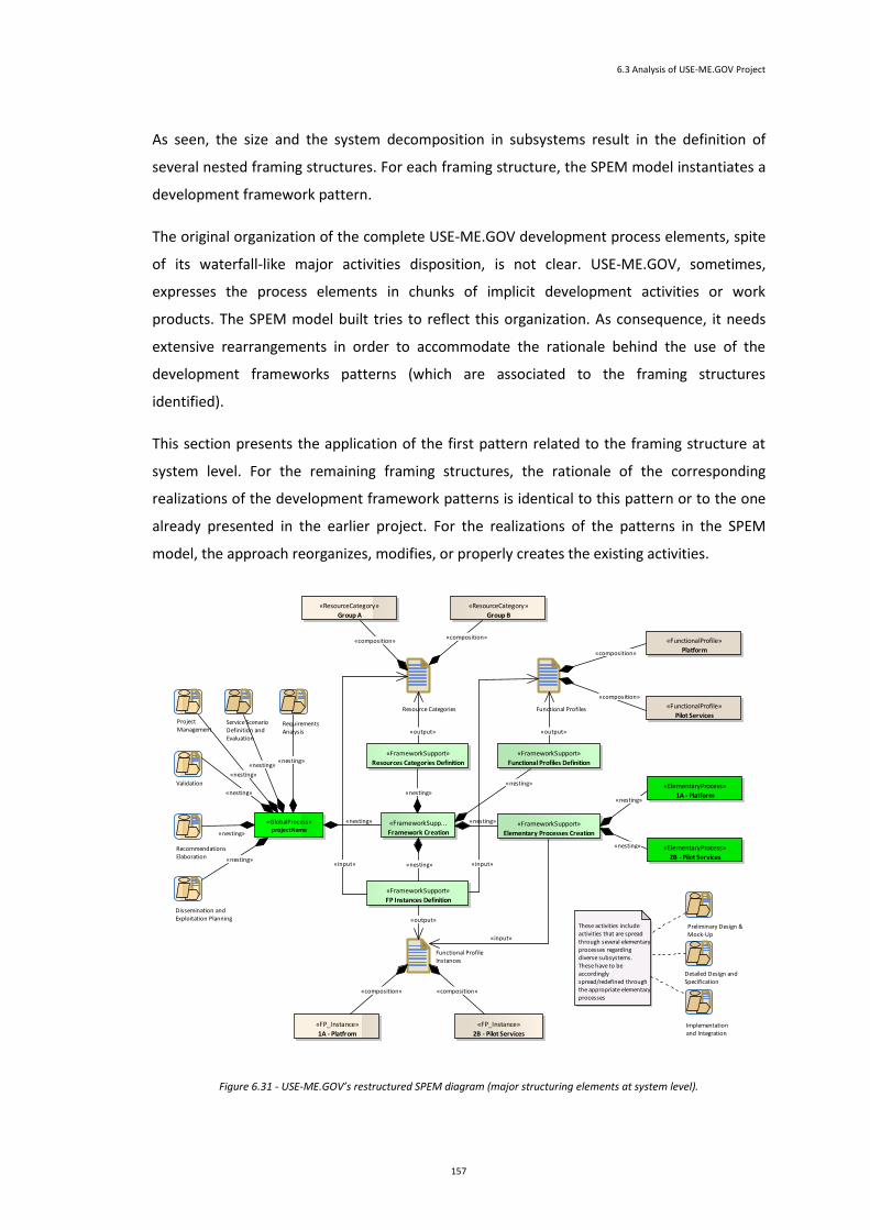
6.3 Analysis of USE-ME.GOV Project
157
As seen, the size and the system decomposition in subsystems result in the definition of
several nested framing structures. For each framing structure, the SPEM model instantiates a
development framework pattern.
The original organization of the complete USE-ME.GOV development process elements, spite
of its waterfall-like major activities disposition, is not clear. USE-ME.GOV, sometimes,
expresses the process elements in chunks of implicit development activities or work
products. The SPEM model built tries to reflect this organization. As consequence, it needs
extensive rearrangements in order to accommodate the rationale behind the use of the
development frameworks patterns (which are associated to the framing structures
identified).
This section presents the application of the first pattern related to the framing structure at
system level. For the remaining framing structures, the rationale of the corresponding
realizations of the development framework patterns is identical to this pattern or to the one
already presented in the earlier project. For the realizations of the patterns in the SPEM
model, the approach reorganizes, modifies, or properly creates the existing activities.
Figure 6.31 - USE-ME.GOV’s restructured SPEM diagram (major structuring elements at system level).
Requirements Analysis
Service Scenario Definition and Evaluation
Preliminary Design & Mock-Up
Detailed Design andSpecification
Implementation and Integration
Validation
Dissemination and Exploitation Planning
Project Management
Recommendations Elaboration
«FrameworkSupp...
Framework Creation
«FrameworkSupport»
Functional Profiles Definition
«FrameworkSupport»
FP Instances Definition
«FrameworkSupport»
Elementary Processes Creation
«FrameworkSupport»
Resources Categories Definition
Resource Categories Functional Profiles
Functional Profile Instances
«GlobalProcess»projectName
«ResourceCategory»
Group A
«ResourceCategory»
Group B
«FunctionalProfile»
Platform
«FunctionalProfile»
Pilot Services
«ElementaryProcess»
1A - Platform
«ElementaryProcess»
2B - Pilot Services
«FP_Instance»
1A - Platfrom
«FP_Instance»
2B - Pilot Services
These activities include activities that are spread through several elementary processes regarding diverse subsystems.These have to be accordingly spread/redefined through the appropriate elementary processes
«input»
«composition»
«nesting»
«nesting»
«composition»
«composition»
«composition» «composition»
«output»
«nesting»
«input»
«nesting»
«composition»
«input» «nesting»
«output»
«nesting»
«nesting»
«nesting»
«nesting»
«nesting»
«nesting»
«nesting»
«nesting»
«output»

Analysis of the Projects
158
The global process activity of “Project Management” includes “Project Coordination” and
“Project Assessment” activities. “Recommendations” global process activity includes
“Business Planning”, “Implementation Planning”, and “Standardization and Regulations”
activities. The restructuration has to distribute (and eventually to redefine) the activities of
“Preliminary Design & Mock-Up”, “Detailed Design ad Specification”, and “Implementation
and Integration” by the several elementary processes regarding diverse subsystems.
Figure 6.32 illustrate the nesting of a framing structure achieved through new realization of
the development framework pattern in connection to an elementary process of a higher
framing structure. This elementary process assumes in the pattern the place usually allocated
to the global development process. Note that there is a namespace established by the
framing structure, reflected in this case by the symbolic designation of the element that is
representing the global process, in this case the elementary process “1A-Platform”. As such,
the absolute name of another relative identified element in the diagram will be, its element’s
type reference followed by a tag in the form 1A.relative_id_of_diagramElement. For example,
“elementary process 1A.3C” refers to the elementary process “3C-Platform Services”.
Figure 6.32 - USE-ME.GOV restructured SPEM diagram (major structuring elements at Platform subsystem level).
Preliminary Design & Mock-Up
Detailed Design andSpecification
Implementation and Integration
«FrameworkSupp...
Framework Creation
«FrameworkSupport»
Functional Profiles Definition
«FrameworkSupport»
FP Instances Definition
«FrameworkSupport»
Elementary Processes Creation
«FrameworkSupport»
Resources Categories Definition
Resource CategoriesFunctional Profiles
Functional Profile Instances
«ResourceCategory»
Group A
«ResourceCategory»
Group B
«FunctionalProfile»
Core Platform
«FunctionalProfile»
External Data Sources
«ElementaryProcess»
1A - Platform
«ElementaryProcess»
2B - Service Repository
«FP_Instance»
1A - Platfrom
«FP_Instance»
5D - Pilot Services
These activities include activities that are spread through several elementary processes regarding diverse subsystems.These have to be accordingly spread/redefined through the appropriate elementary processes
«ResourceCategory»
Group C
«ResourceCategory»
Group D
«ResourceCategory»
Group E
«FunctionalProfile»
Service Repository
«FunctionalProfile»
Platform Services
«FunctionalProfile»
Management Console
«ElementaryProcess»
1A - CorePlatform
«FP_Instance»
2B - Service Repository
«FP_Instance»
3C - Platform Services
«FP_Instance»
4D - Management Console
«ElementaryProcess»
3C - Platform Services
«ElementaryProcess»
4D - Management Console
«ElementaryProcess»
5D - External Data sources
«composition»
«input»
«output»
«nesting»
«input»
«nesting»
«output»
«composition»
«composition»
«composition»
«composition»
«nesting»
«input»
«composition»
«nesting»
«nesting»
«output»
«nesting»
«composition» «composition»
«composition»
«composition»
«composition»
«composition»
«composition» «composition» «composition»
«nesting»
«nesting»
«nesting»
«nesting»
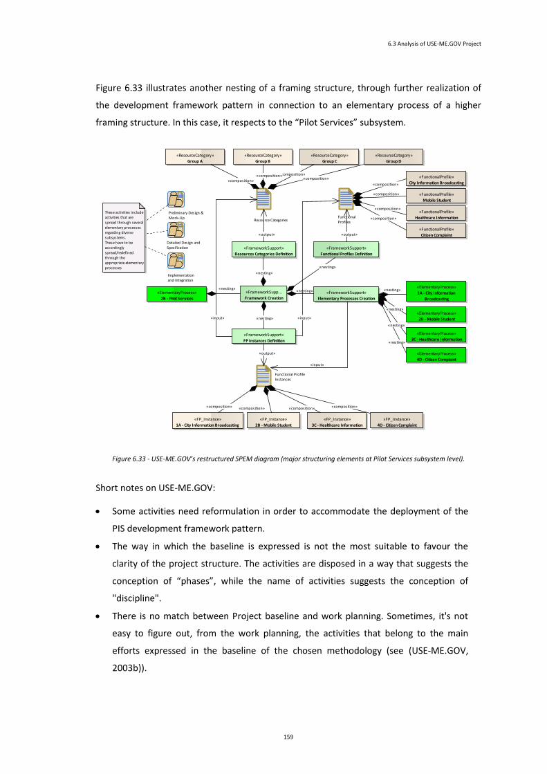
6.3 Analysis of USE-ME.GOV Project
159
Figure 6.33 illustrates another nesting of a framing structure, through further realization of
the development framework pattern in connection to an elementary process of a higher
framing structure. In this case, it respects to the “Pilot Services” subsystem.
Figure 6.33 - USE-ME.GOV’s restructured SPEM diagram (major structuring elements at Pilot Services subsystem level).
Short notes on USE-ME.GOV:
Some activities need reformulation in order to accommodate the deployment of the
PIS development framework pattern.
The way in which the baseline is expressed is not the most suitable to favour the
clarity of the project structure. The activities are disposed in a way that suggests the
conception of “phases”, while the name of activities suggests the conception of
"discipline".
There is no match between Project baseline and work planning. Sometimes, it's not
easy to figure out, from the work planning, the activities that belong to the main
efforts expressed in the baseline of the chosen methodology (see (USE-ME.GOV,
2003b)).
Preliminary Design & Mock-Up
Detailed Design andSpecification
Implementation and Integration
«FrameworkSupp...
Framework Creation
«FrameworkSupport»
Functional Profiles Definition
«FrameworkSupport»
FP Instances Definition
«FrameworkSupport»
Elementary Processes Creation
«FrameworkSupport»
Resources Categories Definition
Resource CategoriesFunctional Profiles
Functional Profile Instances
«ResourceCategory»
Group A
«ResourceCategory»
Group B
«FunctionalProfile»
City Information Broadcasting
«ElementaryProcess»
2B - Pilot Services
«ElementaryProcess»
2B - Mobile Student
«FP_Instance»
1A - City Information Broadcasting
These activities include activities that are spread through several elementary processes regarding diverse subsystems.These have to be accordingly spread/redefined through the appropriate elementary processes
«ResourceCategory»
Group C
«ResourceCategory»
Group D
«FunctionalProfile»
Mobile Student
«FunctionalProfile»
Healthcare Information
«FunctionalProfile»
Citizen Complaint
«ElementaryProcess»
1A - City Information
Broadcasting
«FP_Instance»
2B - Mobile Student
«FP_Instance»
3C - Healthcare Information
«FP_Instance»
4D - Citizen Complaint
«ElementaryProcess»
3C - Healthcare Information
«ElementaryProcess»
4D - Citizen Complaint
«composition»
«composition»
«nesting»
«nesting»
«nesting»
«output»
«composition»
«nesting»
«nesting»
«composition»
«composition»
«composition»
«composition»
«composition»
«output»
«composition»
«nesting»
«composition»
«nesting»
«composition»
«nesting»
«input»
«nesting»
«output»
«input» «input»
«composition»

Analysis of the Projects
160
Some activities do not have proper names and are not consistent with the respective
work product output (ex: "Requirements Revision" task and its resulting "Pilot Services
Requirements Specifications").
Work products should have had a clear, distinct formalization on the project structure.
6.4 Lessons Learned
Resorting to SPEM 2.0 diagrams allowed, along with the conceptions and structures of the
proposed approach, to reveal the internals of projects. Based on intervention on the SPEM
model of each the projects, the scattered observation of the SPEM structure and the analysis
of the suitability of approach’s conceptions accommodation, it was possible to stress out
pertinent issues.
Among several issues detected are the following: the lack of explicit artefacts, activities, or
relationships among them; the inconsistent or improper naming; the incoherent sequence
activities; the improper formalization of process elements; the misused process conceptions;
the improper granularity of activities and artefacts; the inappropriate structural organization
to deal with pervasive issues.
Considering the projects goals, the resulting artefacts, as well the means of achieving those in
the projects, several facts, and pertinent issues about can be point out. Regarding
pervasiveness of the systems, some questions may raise up, such as: (i) how well the system
will adapt for new resources (as or new kind of mobile/embedded computing devices or
smart phones); (ii) how much and how coherently structured development effort will be
needed in order to reflect those changes, or changes on functional requirements.
The projects revealed a structure of development that can difficult its resilience to deal with
some perverseness issues, such as addition of different resources categories or addition of
functionalities specific one or several resources. The projects used models to express their
development work, and in some parts, explicit model transformations were expressed. The
model-driven/visibility of the projects, while explicit at a high-level of activities and products,
could be improved at its and clarity a low or more detailed level. The PIS development
pattern allowed perceiving how they could be structured in order to enhance their capability
to deal with pervasiveness.
6.4 Lessons Learned
161
The following paragraphs synthesises some of the lessons learned.
Need for explicit manifestation of model-driven approach for PIS. The projects did not make
explicitly clear in the project design the strategy to accommodate a model-driven approach
appropriate for PIS, spite of using models in the several phases of the project.
Ensure properly defined elements. The use SPEM 2.0 to represent a project facilitates the
analysis of a project in order to correct mistakes or poorly defined elements. It is important
pay attention for several issues. Among these, is the lack of explicit artefacts, activities, or
relationships among them; the inconsistent or improper naming; the incoherent sequence
activities; or the misused of conceptions. The attention given to them is the belief that they
are a core level at which is fundamental to assure that the process is well defined in order to
pursuit, at higher levels, the goals of model-driven development. A SPEM like standard can be
used to specify/verify the project.
Formalize of activities as model transformations and other elements with correctness.
Without having a coherent, consistent, and clear formalization of the several projects
constituents’ elements, it will not be possible to establish, with an acceptable quality, a
model-based/driven process development. Without the existence of coherently
interconnected and precise process elements, it is hard, even impossible, to a large extent
and depth of the process to achieve a model-based/driven development orientation. This is
consequence of the difficulties in: (i) incorporating new activities or optimizing the existing
ones with model transformations techniques; (ii) reorganizing or redefining the process in
order to pursuit a clearer and enhanced model-based/driven quality. A SPEM like standard
can help to formalize the model transformation.
Seek model-driven semantic continuity/visibility. How much model-based/driven is a
software development process? When does a software development project go from
being model-“based” to being model-“driven”? Towards the answers to these questions, it
is suggested that model-based/driven extension and depth can be made visible in SPEM
2.0 diagrams, allowing one to reason about the robustness of process and suitability of
activities and artefacts regarding its use on a model-based/driven orientation. The
suitability of an artefact is related to its expression and ability to be consumed/reused on
subsequent modelling tasks. The suitability of an activity is related to its ability to
incorporate formal/explicit model transformation techniques that (optionally) consume
models and produce models. The robustness of the process is related to the degree of the
modelling semantic continuity provided by the chains of activities, from the beginning to
the end of the development process. The links among model artefacts and model

Analysis of the Projects
162
transformation activities (or well-structured and formalized activities) of the process
define the visibility. The longer the path, the more model-driven is the development
process. So, to enhance model-based/driven visibility, it is needed to pay attention to
activities (or tasks) and the realization and flow of models. This perspective allows to
materialize, through graphical presentation, the concept of model-based/driven visibility
of a process Visibility can be expressed in a SPEM diagram. This concept constitutes a tool
that can assist an approach to process analysis or optimization. Figure 6.34 depicts (as a
non-SPEM-based example) a general schematic (not exhaustive) of the structure of the
models, transformation models, code generation, and code resulting from and insight into
artefacts produced on the project development.
Structure the design of the project in order to properly support PIS. The way the elements
are structured can have a positive impact to way the project cope with heterogeneity in
devices and in functionalities of PIS. Consider to use a SPEM 2.0 diagram (or an equivalent
representation) as a mean to express the intended/designed software development project
for PIS. Use the proposed development structure approach, which provides assisting
techniques to deal with pervasive characteristics such as heterogeneity of devices and
changing functionalities. Among these techniques, is the framing structure that helps to
Figure 6.34 – Models, model mappings/transformations, and code generation in the development of the uPAIN system.

6.4 Lessons Learned
163
define resources categories, functional profiles, and functional profile instances. The
proposed PIS development framework pattern makes use of them later. The application of
this pattern assumes a SPEM 2.0 diagram. Nevertheless, the application of the patterns can
resort to other forms of representation as long as there is respect to the principles of
patterns’ conceptions and architecture. To each of the elementary process of the pattern,
connect the development process aimed for that development structure (related to a specific
functional profile instance).
Verify the structural quality of the project. For the global and elementary process activities,
and recursively its constituents, verify if they reflect quality properties that avoid the issues
aforementioned. Some guidelines can provide some useful orientations to assure a robust
development process definition. These guidelines take the form of questions to help to look
for and to measure relevant properties that contribute for the perception of the quality of
the approach, and establish solid ground for project development. These properties are next
presented, complemented with guideline question(s) to assist in discovering the proper value
those:
Comprehensiveness and depth – Do all the phases and major activities, explicitly
define the tasks, subtasks, artefacts, deliverables and other process elements?
Semantic correctness – Does the process structure definition use correctly the process
elements types?
Naming coherency and consistency – Do the names of the process elements
adequately reflect its contents? Are the names consistently structured/build among
the same types of process elements?
Flows clearness – Does the process clearly define the flows of execution among units
of work, expressing precedence, parallelism or other execution flow dependency?
Input/output clearness – Does the project clearly and completely express, for each
unit of work, artefacts used as inputs and produced/changed as outputs?
Work unit’s robustness – Are the work unit’s inner construction based on explicit
steps and robust techniques for the transformation of inputs into the expected
outputs? Are they, or can they, be specified in SPEM 2.0 like specification?
Overall rationale robustness - Does the overall structure provide a convincing
rationale for efficient project development?
Seek to achieve a significant for model-based/driven visibility.
Projects of these types, aiming to embrace a model-based driven perspective to develop
software for pervasive information systems, have to give attention to the issues

Analysis of the Projects
164
aforementioned. It is expected that model-based/driven visibility concept constitute an
effective contribution for the acceptance of model-based/driven development, not as a
utopia, but as a viable practice into which firm convictions and deeper efforts can be made.
Among these efforts are directed research investment, gradual and normative adoption of
modelling/process best practices and standards.
6.5 Conclusion
This analysis resorts to SPEM 2.0 for building the diagrams. It enables to depict clearly the
structure of projects, making their main activities, artefacts, and relationships among them
graphically visible. Resorting to SPEM 2.0 for looking into the projects revealed a proper way
to bring to light the understanding of the process internals. In this chapter, the projects are
observed with the conceptual framework constructed by the approach developed in previous
chapter. For each of the projects, this document presented the built SPEM model of the
project, and the deployment of the approach conceptions elaborated in chapter 5. This
allowed deducing relative considerations and generalizations.
The proposed approach revealed to be an effective, well-structured, and reasoned way to
assist in the analysis of existent SPEM-based projects or to development of new pervasive
information systems based on a model-based/driven approach. As it can be reasoned out
from the approach use in projects, the development framework pattern deals well either in
the context of small or large projects. It allows to: (i) clearly sustain a structured and well-
organized set of development process elements; (ii) to suitable cope with the heterogeneity
and quantity of computation devices (through the concepts of resources categories,
functional profiles, and functional profile instances); (iii) to promote a model-based/driven
approach to software development (through use of transformations and the conception of
mode-based/driven visibility).

Chapter 7
Conclusion
Chapter Contents
7 Conclusion ........................................................................................................................................... 167
7.1 Focus of the Work ......................................................................................................................... 167
7.2 Synthesis of Research Efforts ........................................................................................................ 169
7.3 Synthesis of Scientific Results ....................................................................................................... 170
7.4 Future Work .................................................................................................................................. 172

166

167
7
Conclusion
This chapter is the conclusion of this work. It contextualizes the work in the thematic
of pervasive and modelling. It then synthesizes the research efforts, the results that
express the contributions of the thesis, and proposes future work.
7.1 Focus of the Work
Information accessibility is a key factor for efficient use and integration of information on an
organization. Over networked computing devices, software systems store, process, and
interchange information with other applications, fulfilling a planned and established role in
the overall organization’s information system. Pervasive systems and technologies have been
increasingly employed in business domains, trying to improve the way business is done or
even to enable new and innovative ways of carrying business. In in more personal or social
domains, they have been employed to improve the people’s life quality. Nowadays, pervasive
computing systems are still considered a "special" kind of systems; however, in a near future
they will be so common that nobody will consider them “special" anymore. This will demand
a completely transparent capability of designing computing solutions by means of model
manipulations and technology abstraction.
Considering the potential large number of computational devices, their high heterogeneity,
and increasingly frequent changes needed on software at device and system levels, it turns
out that it is needed attention to design methodology in order to define and apply best

7 Conclusion
168
approaches and techniques to software development for pervasive information systems. In
opposite to the past, applications are no longer conceived to be standalone applications
scarcely needing repair, integration, or evolution. Applications must be built to last, to be
integrated, and/or subject to revision or evolution. Their conception and development must
be done with conscientiousness that reality is such adverse that there is a need to have
flexibility to cope with changes on the previous established requirements or in technology.
Software supporting pervasive information systems is target of frequent modifications due
either to technological evolutions or to requirement changes. This requires that software
development process and process elements (for example, activities, tasks, and artefacts)
must be, in its essence, well-structured, designed, and developed. By this way, it will be
possible to satisfy requirements and explore the potential offered by the pervasive
computing, maximizing the revenue of this kind of systems. In particular, model-driven
development (MDD) approaches, currently in research at academic and industrial arenas,
offer potential benefits that can be applied to design and evolution of these pervasive
information systems. Model-driven development approaches promote the idea that, through
focus of development on models, one can obtain better software systems development and
evolutions. They also allow for higher independence of technological platforms, reduction of
semantic gaps, greater development productivity, and longevity of software artefacts. MDD
approaches essentially centre the focus of development on models, involving concepts such
as Platform-Independent Models, Platform-Specific Models, model transformations, and use
of established standards.
This thesis focus on software development of for pervasive information systems, aiming to
contribute to an increased efficiency and effectiveness on development of ubiquitous
services/applications, supported on pervasive information systems (PIS). These PIS are
composed of conveniently orchestrated embedded or mobile computing devices. The
definition and correct use of model-based/driven MDD-based conceptions, techniques, and
procedures to software development for PIS assume major importance on current days.
The thesis uses two projects. The first project presented was the uPAIN project (Ubiquitous
Solutions for Pain Monitoring and Control in Post-Surgery Patients), and the second project is
the USE-ME.GOV (USability-drivEn open platform for MobilE GOVernment) project. From
these projects, facts were presented along with methodological contributions, issues, and
challenges pertinent to software development of pervasive information systems on a model-
driven basis.

7.2 Synthesis of Research Efforts
169
7.2 Synthesis of Research Efforts
The effort on analysing real projects whose main purpose is the development of pervasive
computing systems, should be kept by the scientific community to allow a thoroughly
understanding of the fundamental issues that model-based/driven methodologies should be
capable of dealing with.
The work carried out and reflected in this document was achieved through the development
of the following major activities stated in the following paragraphs.
Beginning the work, it was a presentation of an introductory context of the thematic
involved, the goals, the strategy, contributions, and the structure of this document. After this
introduction, several efforts were carried.
It was performed a research on the state-of-art in the area of ubiquitous computing and
model-driven development. This allowed to characterize ubiquitous computing and pervasive
systems and to clarify the distinction between the terms ubiquitous and pervasive, which are
in the literature interchangeably used with the same semantics. It was also expressed
business opportunities brought by pervasive computing, either to improve existent business
models or to enable new business models. It was revealed some social concerns that arise by
the penetration of computing technology in the daily life, which implies the danger of its
misuse in gathering people sensitive information and in controlling or restricting people from
living freely. It was introduced and justified the expression “Pervasive Information Systems”
to refer to information systems that, incorporating pervasive technology and aiming to take
advantage of their potential, have do deal with the characteristics, issues and challenges
inherent to them and to their use.
The projects, uPAIN and USE-ME.GOV, were presented. They represented two projects
dealing with the same pervasive issues a model-based development, but being significantly
different on its size. For each project, it was presented the pervasive and modelling
perspectives and the common facts, issues, and challenges of them.
Aiming so assist in the project analysis and, at the same time being able to be used for the
development of new projects, it was introduced new conceptions, conceptual framing
structures, and an extension to SPEM 2.0 Base Plug-In to help to deal with pervasiveness
issues of systems. The resulting knowledge from those conceptions, conceptual framing

7 Conclusion
170
structures, and SPEM extension were materialized into a development framework pattern
conceived for the effect.
The projects were revisited in order to proceed to their analysis. Each project was expressed
in a SPEM diagram. This form of expression of the structure allowed turning graphically
visible their main activities, artefacts, and relationships among them. This helped in
understanding the project’s development process internals. The analysis was performed
using as auxiliary tool the development framework pattern, preceded by framing structures.
7.3 Synthesis of Scientific Results
Based on the SPEM 2.0 model of the project, the scattered observation of the SPEM structure
and the analysis of the suitability of approach’s conceptions accommodation, it is possible to
stress out pertinent issues in the context of the perceived generic project orientations.
For sake of enforcement of a methodological model-development orientation, it is needed
greater clarity and well-defined establishment of the structure and elements of a
development process. Avoiding some flaws or omissions on process definition brings several
important benefits as it can contribute for a better development project, either structurally
or dynamically in the course of the project development. Solid project structures ease
process analysis, facilitate the adoption of efforts for optimization, make processes
consistently reusable, allow processes to be more resilient to occasional but necessary
process changes, and give higher confidence to stakeholders regarding processes’ quality and
success. In the course of the project development, it is assured that are no
misunderstandings regarding interpretation objectives, activities, artefacts, and the flow of
either activities or the input/output artefacts among activities. The communication among
stakeholders is clearer, and process planning can be more complete and precise in the
definition of its elements, which may result on better estimation of time and effort to
conclude the project.
The consideration of these issues and challenges, in the context of achieving an effective way
to develop software for PIS, allows one develop consistent and coherent efforts in order to
improve software development for PIS projects. By this way, one can expect a progression
towards the establishment of well-established foundations for smooth model-based/driven
software development suitable the effective construction of pervasive information systems.
This thesis provides several contributions. Among these contributions are:

7.3 Synthesis of Scientific Results
171
Development Framework. Due to the complexity of pervasive information systems,
software development for PIS can be facilitated by an approach that properly focuses
the system, and the system development, with perspectives that help to abstract their
relevant properties. The approach to PIS development proposes a development
framework that encompasses concepts suitable for the model-based/driven
development of pervasive information systems. This framework introduces and
describes the concepts sustained on a few perspectives of relevance to the
development, called dimensions of development .Besides the dimensions of
development, there are the functional profiles, resources categories, functional profile
instances, global and elementary development process.
SPEM Base 2.0 Plug-In Extension. Software and Systems Process Engineering Meta-
Model 2.0 (SPEM 2.0) provides to process engineers a conceptual framework for
modelling method contents and processes. SPEM2. 0 is defined as a meta-model as
well as a UML 2 Profile (concepts are defined as meta-model classes as well as UML
stereotypes). SPEM 2.0 meta-model describes the structures and the structuring rules
needed to express and maintain development method content and processes. In
consonance with this development framework, the thesis proposes a SPEM 2.0 Base
Plug-In extension and a development framework pattern to assist in the analysis of
the projects. The SPEM 2.0 Base Plug-In extension defines elements that are
fundamental to the definition and application of a development framework pattern.
Development Framework Pattern. Taking into account the extension of SPEM 2.0
Base Plug-In, the conceptions in the development framework, and the context
software development for PIS, it is suggested the use of a SPEM-based PIS’s
development framework pattern to assist in the task of defining or restructuring a
SPEM-based software development approach. The thesis defines a development
framework pattern that may be applied each of the projects to facilitate the analysis,
and also to illustrate how projects could be improved in order to better cope with the
development of PIS and adopting a model-based/driven approach.
Insight to PIS development using MDD approaches. Software & Systems Process
Engineering Meta-Model Specification v2.0 (SPEM 2.0) allows to represent in a
suitable form the structure and elements of projects, allowing to proceed with an
analysis about their suitability for PIS and the model-based/driven characteristics.
From the analysis of the projects, the thesis synthesizes a set of pertinent issues that
hamper or difficult the proper suitability of the project to cope with pervasive systems
(in particular issues related with heterogeneity), and to support model-based/driven
approaches. It provides guidelines to the adoption of model-based/driven approaches

7 Conclusion
172
to pervasive information system development. It shows how the projects could
improve to deal with PIS, using an MDD approach.
During this thesis, some presentations and publications were made. The doctoral proposal
was presented in the Symposium for PhD students in Software Engineering, SEDES’2004 (J. E.
Fernandes, 2004), and the publications made were:
Paper with the title “Model-Driven Methodologies for Pervasive Information Systems
Development (J. E. Fernandes, Machado, & Carvalho, 2004b) in MOMPES’04
Conference.
Paper with the title “Model-Driven Software Development for Pervasive Information
Systems Implementation”, in QUATIC 2007 Conference (J. E. Fernandes, Machado, &
Carvalho, 2007).
Book chapter with the title “Model-Driven Development for Pervasive Information
Systems”, in the book “Advances in Ubiquitous Computing: Future Paradigms and
Directions”, from IGI Publishing (J. E. Fernandes, Machado, & Carvalho, 2008).
Additionally, it is expected further publications from this dissertation related to the results
and conclusion of the analysis of projects.
7.4 Future Work
Research of model-based/driven development (MDD) approaches for pervasive information
systems (PIS) tries to raise and to bring light to several issues (such as essential
considerations, techniques, frameworks, tools, etc.) pertaining to the strong adoption of
models for these kinds of systems.
In a vision of model-based/driven development for pervasive information systems, several
issues can be further explored, namely:
Further formalization of the development framework and conceptions, providing
suitable representation of resource categories, research of functional profiles, and
functional profiles instantiation.
Further exploration of the development framework pattern.
Incorporation of the extending SPEM Base Plug-In concepts into the SPEM
metamodel.
Formalization of the model-based/driven visibility of processes and further
exploration of the quality of modelling semantic continuity provided in the chain, or

7.4 Future Work
173
parts of it. This effort can look for common semantic gaps found on common
processes. It can also establish possible model transformation activities/techniques
that can be used to make this semantic continuity to look like a smooth walk rather
than a hard jump, or even an impossible crossing.

175
References
Abowd, G. D., & Mynatt, E. D. (2000). Charting Past, Present, and Future Research in Ubiquitous Computing. ACM Transactions on Computer-Human Interaction, 7(1), 29-58. doi: http://doi.acm.org/10.1145/344949.344988
Abowd, G. D., Mynatt, E. D., & Rodden, T. (2002). The human experience [of ubiquitous computing]. Pervasive Computing, IEEE, 1, 48-57.
Accenture. (2004a). Freight tracking Retrieved 08 August 2006, from http://www.accenture.com/Global/Services/Accenture_Technology_Labs/R_and_I/FreightTracking.htm
Accenture. (2004b). Manufacturing services Retrieved 08 August 2006, from http://www.accenture.com/Global/Services/Accenture_Technology_Labs/R_and_I/ManufacturingServices.htm
Accenture. (2004c). Networked Automation Retrieved 08 August 2006, from http://www.accenture.com/Global/Services/Accenture_Technology_Labs/R_and_I/NetworkedNetwork.htm
Accenture. (2004d). Physical media tracking Retrieved 08 August 2006, from http://www.accenture.com/Global/Services/Accenture_Technology_Labs/R_and_I/PhysicalTracking.htm
Accenture. (2004e). Real-world showroom Retrieved 08 August 2006, from http://www.accenture.com/Global/Services/Accenture_Technology_Labs/R_and_I/RealWorldShowroom.htm
Accenture. (2004f). Ubiquitous and Mobile Computing: Accenture Technology Labs Retrieved 08 August 2006, from http://www.accenture.com/Global/Services/Accenture_Technology_Labs/UbiquitousLabs.htm
Accenture. (2004g). Virtual Home Improvement Services Retrieved 08 August 2006, from http://www.accenture.com/Global/Research_and_Insights/By_Subject/Enterprise_Integration/VirtualServices.htm

References
176
Adi. Agência de Inovação (Adi) Retrieved October 2006, 11th, from http://www.adi.pt/
Alhir, S. (2003). Understanding the Model Driven Architecture.
Anne, A. (1999). Users' perception of privacy in multimedia communication CHI '99 extended abstracts on Human factors in computing systems %@ 1-58113-158-5 (pp. 53-54). Pittsburgh, Pennsylvania: ACM Press.
Apple. (2010). The iPAD Retrieved 2010-10-22, from http://www.apple.com/ipad/
Appukuttan, B., Clark, T., Reddy, S., Tratt, L., & Venkatesh, R. (2003). A model driven approach to model transformations. Proceedings of Model Driven Architecture: Foundations and Applications (CTIT Technical Report TR–CTIT–03–27, University of Twente).
Arakne. Arakne home page Retrieved December 1st, 2006, from http://www.arakne.it/azienda/azienda_ing.html
Ark, W. S., & Selker, T. (1999). A look at human interaction with pervasive computers. IBM Systems Journal, 38(4), 504-507.
Atkinson, C., & Kuhne, T. (2003). Model-driven development: a metamodeling foundation. Software, IEEE, 20(5), 36-41.
Banavar, G., Beck, J., Gluzberg, E., Munson, J., Sussman, J., & Zukowski, D. (2000). Challenges: an application model for pervasive computing. Paper presented at the 6th annual international conference on Mobile Computing and Networking, Boston-Massachusetts, United States.
Banavar, G., & Bernstein, A. (2002). Software infrastructure and design challenges for ubiquitous computing applications. Communications of ACM, 45(12), 92-96. doi: http://doi.acm.org/10.1145/585597.585622
Barton, J., & Kindberg, T. (2001, 08 August 2006). The Cooltown User Experince, from http://www.hpl.hp.com/techreports/2001/HPL-2001-22.pdf
Beckwith, R. (2003). Designing for ubiquity: the perception of privacy. [Magazine Article]. Pervasive Computing, IEEE, 2(2), 40-46.
Bell Labs. (03 August 2006). The transistor, from http://www.lucent.com/minds/transistor/
Beresford, A. R., & Stajano, F. (2003). Location privacy in pervasive computing. [Magazine Article]. Pervasive Computing, IEEE, 2(1), 46-55.
Birnbaum, J. (1997). Pervasive Information Systems. Communications of ACM, 40(2), 40-41. doi: http://doi.acm.org/10.1145/253671.253695
Bohn, J., Coroamã, V., Langheinrich, M., Mattern, F., & Rohs, M. (2004). Living in a world of smart everyday objects - social, economic, and ethical implications. Human and Ecological Risk Assessment, 10(5).
Bologna. Bologna city's home page Retrieved December 1st, 2006, from http://www.comune.bologna.it/

References
177
Booch, G., Maksimchuk, R. A., Engle, M. W., Young, B. J., Conallen, J., & Houston, K. A. (2007). Object-Oriented Analysis and Design with Applications: Addison-Wesley.
Brown, A. W. (2004). Model driven architecture: Principles and practice. Software and Systems Modeling, 3, 314-327.
Burrell, J., Brooke, T., & Beckwith, R. (2004). Vineyard computing: sensor networks in agricultural production. Pervasive Computing, IEEE, 3, 38-45.
Ciarletta, L., & Dima, A. (2000). A conceptual model for pervasive computing. Paper presented at the Parallel Processing, 2000. Proceedings. 2000 International Workshops on.
CORDIS. USE-ME.GOV Project Fact Sheet Retrieved November 29, 2006, from http://cordis.europa.eu/fetch?CALLER=FP6_PROJ&ACTION=D&DOC=1&CAT=PROJ&QUERY=1164804162217&RCN=74677
Davies, N., & Gellersen, H.-W. (2002). Beyond prototypes: challenges in deploying ubiquitous systems. Pervasive Computing, IEEE, 1, 26-35.
Debaty, P., Goddi, P., & Vorbau, A. (2005). Integrating the Physical World with the Web to Enable Context-Enhanced Mobile Services. Mobile Networks and Applications, 10(4), 385-394.
Denno, P., Steves, M. P., Libes, D., & Barkmeyer, E. J. (2003). Model-driven integration using existing models. Software, IEEE, 20(5), 59-63.
Dryer, D. C., Eisbach, C., & Ark, W. S. (1999). At what cost pervasive? A social computing view of mobile computing systems. IBM Systems Journal, 38(4), 652-676.
EDISOFT. (December 1st, 2006). EDISOFT, from http://www.usemegov.org/partners/portugal.php
ElMundo. Amena y Wanadoo se 'pintan' de Orange Retrieved December 1st, 2006, from http://www.elmundo.es/mundodinero/2006/09/22/economia/1158912649.html
Elrod, S., Pier, K., Tang, J., Welch, B., Bruce, R., Gold, R., . . . Pedersen, E. (1992). Liveboard: a large interactive display supporting group meetings, presentations, and remote collaboration. Paper presented at the Conference on Human Factors in Computing Systems, Monterey, California, United States.
Fano, A., & Gershman, A. (2002). The future of business services in the age of ubiquitous computing. Communications of ACM, 45(12), 83-87.
Fernandes, J., & Machado, R. J. (2001). From use cases to objects: an industrial information systems case study analysis. Paper presented at the 7th Int. Conf. Object-Oriented Informaiton Systems (OOIS'01), Calgary, Canada.
Fernandes, J. E. (2004). Desenvolvimento de Software em Sistemas de Informação Ubíquos: Orientação aos Modelos. Paper presented at the SEDES' 2004 - Simpósio para Estudantes de Doutoramento em Engenharia de Software 2004.
Fernandes, J. E., Machado, R. J., & Carvalho, J. Á. (2004a, May 2004). Model-driven methodologies for pervasive information systems development. Paper presented at
References
178
the MOMPES'04 -1st International Workshop on Model-Based Methodologies for Pervasive and Embedded Software, Hamilton, Ontario, Canada.
Fernandes, J. E., Machado, R. J., & Carvalho, J. Á. (2004b). Model-Driven Methodologies for Pervasive Information Systems Development. Paper presented at the MOMPES'04 -1st International Workshop on Model-Based Methodologies for Pervasive and Embedded Software, Hamilton, Ontario, Canada.
Fernandes, J. E., Machado, R. J., & Carvalho, J. Á. (2007). Model-Driven Software Development for Pervasive Information Systems Implementation. Paper presented at the QUATIC 2007 - 6th International Conference on the Quality of Information and Communications Technology, Lisbon, Portugal. http://apps.isiknowledge.com/full_record.do?product=UA&search_mode=GeneralSearch&qid=3&SID=Z1meCDfeaAPeP@36COg&page=3&doc=23&colname=WOS
Fernandes, J. E., Machado, R. J., & Carvalho, J. Á. (2008). Model-Driven Development for Pervasive Information Systems. In S. K. Mostefaoui, Z. Maamar & G. M. Giaglis (Eds.), Advances in Ubiquitous Computing: Future Paradigms and Directions
(pp. 45-82): IGI Publishing.
FIT. Fraunhofer Institute for Applied Information Technology home page Retrieved December 1st, 2006, from http://www.fit.fraunhofer.de/index_en.html
Fleck, M., Frid, M., Kindberg, T., O'Brien-Strain, E., Rajani, R., & Spasojevic, M. (2002a). From informing to remembering: ubiquitous systems in interactive museums. [Magazine Article]. Pervasive Computing, IEEE, 1(2), 13-21.
Fleck, M., Frid, M., Kindberg, T., O'Brien-Strain, E., Rajani, R., & Spasojevic, M. (2002b). From informing to remembering: ubiquitous systems in interactive museums. Pervasive Computing, IEEE, 1, 13-21.
Formatex. Formatex home page Retrieved December 1st, 2006, from http://www.formatex.org/
Gates, B. (2007, Juary, 2007). A Robot in every home. Scientific American, 296, 58-65.
Gdynia. Gdynia city's home page Retrieved December 1st, 2006, from http://www.gdynia.pl/?lang=en
Gershman, A. (2002). Ubiquitous commerce - always on, always aware, always pro-active. Paper presented at the Applications and the Internet, 2002. (SAINT 2002). Proceedings. 2002 Symposium on, Nara, Japan.
GET. Telecomputing Engineering Group (GET) Retrieved December 1st, 2006, from http://get.dsi.uminho.pt/
Gordon, S. R., & Gordon, J. R. (2004a). Information Systems (3rd ed.): Wiley.
Gordon, S. R., & Gordon, J. R. (2004b). Information Systems - A Management Approach (3rd ed.).
Grimm, R. (2004). One.world: Experiences with a Pervasive Computing Architecture. Pervasive Computing, IEEE, 03, 22-30.

References
179
Grimm, R., Davis, J., Hendrickson, B., Lemar, E., MacBeth, A., Swanson, S., . . . Wetherall, D. (2001). Systems directions for pervasive computing. Paper presented at the Eighth Workshop on Hot Topics in Operating Systems.
Gupta, S. K. S., Wang-Chien, L., Purakayastha, A., & Srimani, P. K. (2001). An overview of pervasive computing. Personal Communications, IEEE [see also IEEE Wireless Communications], 8(4), 8-9.
Hansmann, U., Merck, L., Nicklous, M. S., & Stober, T. (2003). Pervasve Computing (2nd ed.): Springer.
HSOG. Hospital da Senhora da Oliveira, Guimarães Retrieved October 2006, 11th, from http://www.hguimaraes.min-saude.pt/
Indra. Indra home page Retrieved December 1st, 2006, from http://www.indra.es
Intel. Microprocessor Hall of Fame, from http://www.intel.com/museum/online/hist_micro/hof/index.htm
IntuiLab. IntuiLab home page Retrieved December 1st, 2006, from http://www.intuilab.com/presentation/en/index.html
Jacobs, A. R., & Abowd, G. D. (2003). A framework for comparing perspectives on privacy and pervasive technologies. [Magazine Article]. Pervasive Computing, IEEE, 2(4), 78-84.
Jiang, X., & Landay, J. A. (2002). Modeling privacy control in context-aware systems. [Magazine Article]. Pervasive Computing, IEEE, 1(3), 59-63.
JornaldeNegócios. (2005). France Télécom acorda compra de 80% da Amena por 6,4 mil milhões. Retrieved December 1st, 2006, from http://www.jornaldenegocios.pt/default.asp?CpContentId=262619
Kindberg, T., Barton, J., Morgan, J., Becker, G., Caswell, D., Debaty, P., . . . Spasojevic, M. (2000). People, places, things: Web presence for the real world. Paper presented at the Mobile Computing Systems and Applications, 2000 Third IEEE Workshop on.
Kindberg, T., & Fox, A. (2002). System software for ubiquitous computing. Pervasive Computing, IEEE, 1, 70-81.
Langheinrich, M. (2001). Privacy by Design - Principles of Privacy-Aware Ubiquitous Systems Lecture Notes in Computer Science (Vol. 2201, pp. 273).
Langheinrich, M., Coroama, V., Bohn, J., & Rohs, M. (2002). As we may live – Real-world implications of ubiquitous computing: Distributed Systems Group, Institute of Information Systems, Swiss Federal Institute of Technology, ETH Zurich, Switzerland.
Lessig, L. (1999). Code and other Laws of Cyberspace: Basic Books.
Lyytinen, K., & Yoo, Y. (2002). Introduction [Issues and challenges in ubiquitous computing]. Communications of ACM, 45(12), 62-65.
Machado, R. J., Lassen, K. B., Oliveira, S., Couto, M., & Pinto, P. (2007). Requirements Validation: Execution of UML Models with CPN Tools. International Journal on

References
180
Software Tools for Technology Transfer (STTT), 9(3), 353-369. doi: 10.1007/s10009-007-0035-0
Marx, G. T. (2001). Murky conceptual waters: The public and the private. Ethics and Information Technology, 3(3), 157-169.
Mattern, F. (2001). The vision and techical foundations of ubiquitous computing. UPGRADE, 2(5), 3-5.
Mellor, S. J., Clark, A. N., & Futagami, T. (2003). Model-driven development - Guest editor's introduction. Software, IEEE, 20(5), 14-18.
Merriam-Webster. (24 August 2004). Merriam-Webster Online Dictionay, from http://www.m-w.com/
Miller, G., Ambler, S., Cook, S., Mellor, S., Frank, K., & Kern, J. (2004a). Model driven architecture: the realities, a year later. Paper presented at the Companion to the 19th annual ACM SIGPLAN conference on Object-oriented programming systems, languages, and applications, Vancouver, BC, CANADA.
Miller, G., Ambler, S., Cook, S., Mellor, S., Frank, K., & Kern, J. (2004b). (PANEL) Model driven architecture: the realities, a year later Companion to the 19th annual ACM SIGPLAN conference on Object-oriented programming systems, languages, and applications (pp. 138-140). Vancouver, BC, CANADA: ACM Press.
MobiComp. MobiComp - Computação Móvel, Lda, from http://www.mobicomp.com/
OECD. (1980, 08 August 2006). OECD Guidelines on the Protection of Privacy and Transborder Flows of Personal Data, from http://www.oecd.org/document/18/0,2340,en_2649_34255_1815186_1_1_1_1,00.html
OMG. (2003). OMG's MDA Guide Version 1.0.1.
OMG. (2005a). OMG's Home Page.
OMG. (2005b). OMG's UML home page.
OMG. (2008). SPEM - Software & Systems Process Engineering Meta-Model Specification v2.0: OMG.
OMG. (2010). UML Infrastructure Specification v2.3: OMG.
Orange. Orange Mobile Operator home page Retrieved December 1st, 2006, from http://www.orange.es/
PARC. (2004, 18 June 2004). Palo Alto Research Center (PARC) Homepage, from http://www.parc.xerox.com/
PoznanUE. Department of Information Systems at Poznan University of Economics Retrieved December 1st, 2006, from http://www.kie.ae.poznan.pl/
Russell, D. M., & Weiser, M. (1998). The future of integrated design of ubiquitous computing in combined real & virtual worlds. Paper presented at the CHI 98 conference

References
181
summary on Human factors in computing systems, Los Angeles, California, United States.
Sage, A. P., & Rouse, W. B. (1999). Information Systems Frontiers in Knowledge Management. Information Systems Frontiers, 1(3), 205-219.
Saha, D., & Mukherjee, A. (2003). Pervasive computing: a paradigm for the 21st century. Computer, 36(3), 25-31.
Samsung. (2010). Galaxy Tab Retrieved 2010-10-22, from http://galaxytab.samsungmobile.com/
Satyanarayanan, M. (2001). Pervasive computing: vision and challenges. Personal Communications, IEEE [see also IEEE Wireless Communications], 8(4), 10-17.
Schmoelzer, G., Teiniker, E., Mitterdorfer, S., Kreiner, C., Kovacs, Z., & Weiss, R. (2004). Model-driven development of recursive CORBA component assemblies. Paper presented at the 30th Euromicro Conference, 2004.
Seidewitz, E. (2003). What models mean. Software, IEEE, 20(5), 26-32.
Selic, B. (2003a). Model-driven development of real-time software using OMG standards. Paper presented at the Sixth IEEE International Symposium on Object-Oriented Real-Time Distributed Computing, 2003 (ISORC'03).
Selic, B. (2003b). The pragmatics of model-driven development. Software, IEEE, 20(5), 19-25.
Sendall, S., & Kozaczynski, W. (2003). Model transformation: the heart and soul of model-driven software development. Software, IEEE, 20(5), 42-45.
Sommerville, I. (2001). Software Engineering (6th ed.): Addison-Wesley.
Stanford, V. (2002). Using pervasive computing to deliver elder care. Pervasive Computing, IEEE, 1, 10-13.
Stanford, V. (2003a). Pervasive computing puts food on the table. Pervasive Computing, IEEE, 2, 9-14.
Stanford, V. (2003b). Pervasive computing puts food on the table. [Magazine Article]. Pervasive Computing, IEEE, 2(1), 9-14.
Stone, A. (2003). The dark side of pervasive computing. Pervasive Computing, IEEE, 2, 4-8.
Strassner, M., & Schoch, T. (2002). Today’s Impact of Ubiquitous Computing on Business Processes.
Suzuki, K. (2004). Ubiquitous services and networking: monitoring the real world. Paper presented at the Applications and the Internet, 2004. Proceedings. 2004 International Symposium on.
Texas Instruments. (20 October 2004). Texas Intruments Innovations, from http://www.ti.com/corp/docs/company/history/innov.shtml
Thomas, D. (2004). MDA: revenge of the modelers or UML utopia? Software, IEEE, 21(3), 15-17.

References
182
Turban, E., McLean, E., & Wetherbe, J. (2001). Information Technology for Management: Transforming Business in the Digital Economy (3rd ed.): John Wiley & Sons Inc.
UMinho-DSI. Minho University's Information System's Department (DSI ) from http://www.dsi.uminho.pt/
uPAIN. uPAIN - Candidatura de Submissão.
uPAIN. (2005a). Relatório Técnico Científico 200503-200508.
uPAIN. (2005b). Relatório Técnico Científico 200509-200602.
uPAIN. (2008). Relatório Técnico Científico 200709-200802.
USDoC. (2000, 08 August 2006). Safe Harbor Framework, from http://www.export.gov/safeharbor/index.html
USE-ME.GOV. USE-ME.GOV project home page [doesn't exist anymore] Retrieved November 28, 2006, from http://www.usemegov.org/
USE-ME.GOV. (2003a). Consortium Agreement.
USE-ME.GOV. (2003b). Consortium Agreement - Annex I - Description of Work.
USE-ME.GOV. (2004a). D2.1.1 User Requirements Analysis.
USE-ME.GOV. (2004b). D2.1.2 Technical Implementation Requirements.
USE-ME.GOV. (2004c). D2.1.3 Review of Available Business Models.
USE-ME.GOV. (2004d). D2.2 Service and Use Scenario Definition.
USE-ME.GOV. (2004e). D4.1.2 Usability Requirement Definition for Selected Scenarios.
USE-ME.GOV. (2004f). D4.1.3 Usability-driven Design and Mock-Up Evaluation.
USE-ME.GOV. (2004g). D5.1.1 Platform Requirements Analysis.
USE-ME.GOV. (2004h). D5.1.2 Platform Preliminary Design and Mock-up Evaluation.
USE-ME.GOV. (2004i). D5.1.3 Platform Architecture Design.
USE-ME.GOV. (2004j). D5.2.4 Meta Protocol of Service Types.
USE-ME.GOV. (2004k). D6.1.1 Pilot Services Requirements Specifications.
USE-ME.GOV. (2004l). D6.1.2 Pilot Services Detailed Services Specification.
USE-ME.GOV. (2005). D7.1 Platform and Application Detailed Design.
USE-ME.GOV. (2006). D3.1 Recommendations.
Vaishnavi, V. K., & Jr., W. K. (2008). Design Science Research Methods and Patterns Innovating Information and Communication Technology: Auerbach Publications.
Varshney, U. (2003). Pervasive healthcare. Computer, 36(12), 138-140.

References
183
Verichip. (2006a, 08 August 2006). Verichip Media Resources, from http://www.verichipcorp.com/content/media/resources
VeriChip. (2006b, 08 August 2006). VeriChip RFID Tags, from http://www.verichipcorp.com/content/company/rfidtags
VeriChip. (2006c, 08 August 2006). VeriChip Solutions, from http://www.verichipcorp.com/solutions.html
VNC-ANMP. Vila Nova de Cerveira Retrieved December 1st, 2006, from http://www.anmp.pt/munp/mun/mun101w3.php?cod=M4920
VNC-CM. Vila Nova de Cerveira Retrieved December 1st, 2006, from http://www.cm-vncerveira.pt/
VNC-RTAM. Vila Nova de Cerveira Retrieved December 1st, 2006, from http://www.rtam.pt/index.php?id_categoria=55
Want, R. (2000). Remembering Mark Weiser: Chief Technologist, Xerox Parc. Personal Communications, IEEE [see also IEEE Wireless Communications], 7(1), 8-10.
Want, R., Hopper, A., Falcão, V., & Gibbons, J. (1992). The active badge location system. ACM Transactions on Information Systems, 10(1), 91.102.
Want, R., Pering, T., Borriello, G., & Farkas, K. I. (2002). Disappearing hardware [ubiquitous computing]. Pervasive Computing, IEEE, 1, 36-47.
Want, R., Schilit, B. N., Adams, N. I., Gold, R., Petersen, K., Goldberg, D., . . . Weiser, M. (1995). An overview of the PARCTAB ubiquitous computing experiment. Personal Communications, IEEE [see also IEEE Wireless Communications], 2(6), 28-43.
Weiser, M. (1991). The Computer for the 21st Century. Scientific American, 265(3), 94-104.
Weiser, M. (1993a). Hot topics-ubiquitous computing. Computer, 26(10), 71-72.
Weiser, M. (1993b). Some computer science issues in ubiquitous computing. Communications of ACM, 36(7), 75-84. doi: http://doi.acm.org/10.1145/159544.159617
Weiser, M. (1994, January 1994). The world is not a desktop [Perspectives]. Interactions, ACM Press, 1, 7-8.
Weiser, M. (1998). The future of ubiquitous computing on campus. Commun. ACM, 41(1), 41-42. doi: http://doi.acm.org/10.1145/268092.268108
Weiser, M., & Brown, J. S. (1997). The coming age of calm technology Beyond calculation: the next fixty years (pp. 75-85): Copernicus.
Weiser, M., Gold, R., & Brown, J. S. (1999). The origins of ubiquitous computing research at PARC in the late 1980s. Ibm Systems Journal, 38(4), 693-696.
Yin, R. K. (2003). Case Study Research - Design Methods (3rd ed.): SAGE Publications.
Yourdon. (1983). Yourdon System Method - Model-Driven Systems Development: Prentice-Hall International, Inc.