Embed Size (px)
DESCRIPTION
Estruturas em Vidro
Citation preview
Report EUR 26439 EN
20 14
AUTHORS: M. Feldmann, R. Kasper and B. Abeln, P. Cruz, J. Belis, J. Beyer, J. Colvin, F. Ensslen, M. Eliasova, L. Galuppi, A. Geßler, C. Grenier, A. Haese, H. Hoegner, R. Kruijs, K. Langosch, Ch. Louter, G. Manara, T. Morgan, J. Neugebauer, V. Rajcic, G. Royer-Carfagni, J. Schneider, S. Schula, G. Siebert, Z. Sulcova, F. Wellershoff, R. Zarnic EDITORS S. Dimova, A. Pinto, M. Feldmann, S. Denton
Support to the implementation, harmonization
and further development of the Eurocodes
Guidance for European Structural Design of Glass Components

European Commission
Joint Research Centre
Institute for the Protection and Security of the Citizen
Contact information
Silvia Dimova
Address: Joint Research Centre, Via Enrico Fermi 2749, TP 480, 21027 Ispra (VA), Italy
E-mail: [email protected]
Tel.: +39 0332 78 9063
Fax: +39 0332 78 9049
http://eurocodes.jrc.ec.europa.eu/
http://elsa.jrc.ec.europa.eu/
This publication is a Scientific and Policy Report by the Joint Research Centre of the European Commission.
Legal Notice
Neither the European Commission nor any person acting on behalf of the Commission
is responsible for the use which might be made of this publication.
Europe Direct is a service to help you find answers to your questions about the European Union
Free phone number (*): 00 800 6 7 8 9 10 11
(*) Certain mobile telephone operators do not allow access to 00 800 numbers or these calls may be billed.
A great deal of additional information on the European Union is available on the Internet.
It can be accessed through the Europa server http://europa.eu/.
JRC 86637
EUR 26439 EN
ISBN 978-92-79-35093-1 (pdf)ISBN 978-92-79-35094-8 (print)
ISSN 1831-9424 (online)ISSN 1018-5593 (print)
doi: 10.2788/5523
Luxembourg: Publications Office of the European Union, 2014
© European Union, 2014
Reproduction is authorised provided the source is acknowledged.
Printed in Italy

Guidance for European Structural Design of Glass Components
Foreword
The construction sector is of strategic importance to the EU as it delivers the buildings and
infrastructure needed by the rest of the economy and society. It represents more than 10% of
EU GDP and more than 50% of fixed capital formation. It is the largest single economic ac-
tivity and it is the biggest industrial employer in Europe. The sector employs directly almost 20
million people. Construction is a key element not only for the implementation of the Single Mar-
ket, but also for other construction relevant EU Policies, e.g. Sustainability, Environment and
Energy, since 40-45% of Europe’s energy consumption stems from buildings with a further 5-
10% being used in processing and transport of construction products and components.
The EN Eurocodes are a set of European standards which provide common rules for the de-
sign of construction works, to check their strength and stability against live extreme loads such
as fire and earthquakes. In line with the EU’s strategy for smart, sustainable and inclusive
growth (EU2020), Standardization plays an important part in supporting the industrial policy for
the globalization era. The improvement of the competition in EU markets through the adoption
of the Eurocodes is recognized in the "Strategy for the sustainable competitiveness of the con-
struction sector and its enterprises" - COM (2012)433, and they are distinguished as a tool for
accelerating the process of convergence of different national and regional regulatory approach-
es.
With the publication of all the 58 Eurocodes Parts in 2007, the implementation in the European
countries started in 2010 and now the process of their adoption internationally is gaining mo-
mentum. The Commission Recommendation of 11 December 2003 stresses the importance of
training in the use of the Eurocodes, especially in engineering schools and as part of continuous
professional development courses for engineers and technicians, which should be promoted
both at national and international level. It is recommended to undertake research to facilitate the
integration into the Eurocodes of the latest developments in scientific and technological
knowledge.
In May 2010 DG ENTR issued the Programming Mandate M/466 EN to CEN concerning the
future work on the Structural Eurocodes. The purpose of the Mandate was to initiate the pro-
cess of further evolution of the Eurocode system. M/466 requested CEN to provide a pro-
gramme for standardisation covering:
• Development of new standards or new parts of existing standards, e.g. a new con-
struction material and corresponding design methods or a new calculation procedure;
• Incorporation of new performance requirements and design methods to achieve fur-
ther harmonisation of the implementation of the existing standards.
Following the answer of CEN, in December 2012 DG ENTR issued the Mandate M/515 EN for
detailed work programme for amending existing Eurocodes and extending the scope of struc-
tural Eurocodes. In May 2013 CEN replied to M/515 EN. Over 1000 experts from across Europe
have been involved in the development and review of the document. The CEN/TC250 work
programme encompasses all the requirements of M/515 EN, supplemented by requirements
established through extensive consultation with industry and other stakeholders. Publishing of
the complete set of new standards is expected by 2019.

Guidance for European Structural Design of Glass Components
Page ii
The standardisation work programme of CEN/TC250 envisages that the new pre-
normative documents will first be published as JRC Scientific and Policy Reports, before
their publication as CEN Technical Specifications. After a period for trial use and comment-
ing, CEN/TC 250 will decide whether the Technical Specifications should be converted into
ENs.
This pre-normative document is published as a part of the JRC Report Series “Support to the
implementation, harmonization and further development of the Eurocodes” and presents Guid-
ance for European Structural Design of Glass Components. It was developed by
CEN/TC250 Working Group (WG) 3 on structural glass. The purpose of its work is to develop
structural design rules for glass components in a stepwise procedure that finally should result
into a new Eurocode on design of structural glass.
This JRC Scientific and Policy Report presents the scientific and technical background of the
design of glass components, basing on a complete state-of-the-art overview of the existing na-
tional codes or rules, and on the most recent scientific knowledge. It presents a harmonized
European view on the contents and the technical rules of the future Eurocode on design of
glass components.
The editors and authors have sought to present useful and consistent information in this
report. However, users of information contained in this report must satisfy themselves of
its suitability for the purpose for which they intend to use it.
The report is available to download from the “Eurocodes: Building the future” website
(http://eurocodes.jrc.ec.europa.eu).
Ispra, December 2013
Silvia Dimova and Artur Pinto
European Laboratory for Structural Assessment (ELSA)
Institute for the Protection and Security of the Citizen (IPSC)
Joint Research Centre (JRC)
Markus Feldmann
RWTH Aachen, Convenor of CEN/TC250 WG3
Steve Denton
Parsons Brinckerhoff, Chairman of TC250

Guidance for European Structural Design of Glass Components
Page iii
Report Series “Support to the implementation, harmonization
and further development of the Eurocodes”
In the light of the Commission Recommendation of 11 December 2003, DG JRC is collaborating
with DG ENTR and CEN/TC250 “Structural Eurocodes”, and is publishing the Report Series
“Support to the implementation, harmonization and further development of the Euro-
codes” as JRC Scientific and Policy Reports. This Report Series includes, at present, the fol-
lowing types of reports:
1. Policy support documents, resulting from the work of the JRC in cooperation with
partners and stakeholders on “Support to the implementation, promotion and further de-
velopment of the Eurocodes and other standards for the building sector”;
2. Technical documents, facilitating the implementation and use of the Eurocodes and
containing information and practical examples (Worked Examples) on the use of the Eu-
rocodes and covering the design of structures or its parts (e.g. the technical reports con-
taining the practical examples presented in the workshop on the Eurocodes with worked
examples organized by the JRC);
3. Pre-normative documents, resulting from the works of the CEN/TC250 and containing
background information and/or first draft of proposed normative parts. These documents
can be then converted to CEN technical specifications.
4. Background documents, providing approved background information on current Euro-
code part. The publication of the document is at the request of the relevant CEN/TC250
Sub-Committee;
5. Scientific/Technical information documents, containing additional, non-contradictory
information on current Eurocode part, which may facilitate its implementation and use, or
preliminary results from pre-normative work and other studies, which may be used in fu-
ture revisions and further developments of the standards. The authors are various
stakeholders involved in Eurocodes process and the publication of these documents is
authorized by relevant CEN/TC250 Sub-Committee or Working Group.
Editorial work for this Report Series is performed by the JRC together with partners and
stakeholders, when appropriate. The publication of the reports type 3, 4 and 5 is made after
approval for publication by CEN/TC250, or CEN/TC250 Coordination Group, or the relevant
Sub-Committee or Working Group.
The publication of these reports by the JRC serves the purpose of implementation, further har-
monization and development of the Eurocodes. However, it is noted that neither the Commis-
sion nor CEN are obliged to follow or endorse any recommendation or result included in these
reports in the European legislation or standardization processes.
The reports are available to download from the “Eurocodes: Building the future” website
(http://eurocodes.jrc.ec.europa.eu).

Guidance for European Structural Design of Glass Components
Page iv
Acknowledgements
This report has been prepared for the development of a future European design standard on
structural glass under the aegis of CEN/TC250. Both CEN/TC250 and JRC acknowledge the
substantial contribution of the many international experts of CEN/TC250/WG3,
CEN/TC129/WG8, COST Action TU0905 and others, who have supported the works by their
essential input and reviews.
Markus Feldmann
RWTH Aachen, Chairman of CEN/TC250 WG3
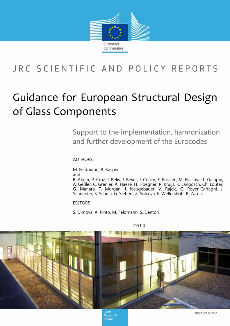
Reference of the front picture:
Pilkington Planar Glazing, St Thomas’s Hospital, UK
(c) ME Construction Ltd, Unit 3 Baden Place, Crosby Row, London, SE1 1YW
(c) Suburbia Photography, 47 Mayflower Way, Farnham Common, Bucks, SL2 3UA
Guidance for European Structural Design of Glass Components
Page I
Contents
1 Introduction and General .................................................................................................... 1
1.1 Establishing of a Eurocode on Structural Glass ............................................................ 1
1.2 Eurocode rules applicable to glass structures............................................................... 3
1.3 Structuring of the Eurocode .......................................................................................... 6
2 Material properties ............................................................................................................ 15
2.1 Glass .......................................................................................................................... 15
2.1.1 General ............................................................................................................... 15
2.1.2 Characteristics of annealed glass ........................................................................ 15
2.1.3 Toughened glass ................................................................................................. 20
2.1.4 Breakage pattern ................................................................................................. 21
2.1.5 Definition of the zones 1 to 4 ............................................................................... 23
2.1.6 Test methods according to EN 1288 ................................................................... 25
2.1.7 Statistical evaluation of the bending strength ...................................................... 27
2.1.8 Quality control by non-destructive methods, stress optics ................................... 28
2.2 Interlayer .................................................................................................................... 28
2.2.1 General ............................................................................................................... 28
2.2.2 Viscoelastic behaviour of interlayers ................................................................... 28
2.2.3 Determination of the viscoelastic behaviour with “small size” tests ...................... 29
2.2.4 Determination of the viscoelastic behaviour in the panel-torsion-test ................... 30
2.2.5 Durability of PVB interlayer ................................................................................. 33
2.2.6 Design shear modulus of PVB- interlayer in dependence of temperature and time during wind loading ........................................................................................................... 34
3 Products ........................................................................................................................... 39
3.1 General ...................................................................................................................... 39
3.2 Float glass .................................................................................................................. 40
3.2.1 General ............................................................................................................... 40
3.2.2 Geometrical properties ........................................................................................ 40
3.2.3 Surface processing ............................................................................................. 41
3.2.4 Forming ............................................................................................................... 41
3.3 Patterned glass .......................................................................................................... 42
3.4 Wired glass ................................................................................................................ 43
3.5 Drawn sheet glass ...................................................................................................... 43
3.6 Thermally toughened glass (TTG) .............................................................................. 43
3.7 Heat strengthened glass (HSG) ................................................................................. 46
3.8 Laminated and laminated safety glass ....................................................................... 47
Guidance for European Structural Design of Glass Components
Page II
3.9 Thermally curved glass .............................................................................................. 50
3.10 Chemically strengthened glass ................................................................................... 51
3.11 Insulating glass .......................................................................................................... 51
3.12 Channel shaped glass ................................................................................................ 52
4 Principles and Basic Rules for the design of glass components and safety approach ....... 55
4.1 General ...................................................................................................................... 55
4.2 Classification of structural elements of glass .............................................................. 61
4.3 Secondary structural elements: robustness and residual capacity .............................. 62
4.3.1 General ............................................................................................................... 62
4.3.2 Composition and strength of the glass section .................................................... 62
4.3.3 Supports and bearing concept ............................................................................. 63
4.3.4 Failure scenario ................................................................................................... 63
4.3.5 Further general construction rules ....................................................................... 65
4.4 Primary structural elements: glass-robustness and damage tolerance ....................... 66
4.5 Special loading situations ........................................................................................... 68
4.5.1 Seismic structures ............................................................................................... 68
4.5.2 Blast loads .......................................................................................................... 70
4.6 Potential classification of glass components ............................................................... 74
5 Mechanical basics and verification approach for monolithic and laminated plates and beams ...................................................................................................................................... 79
5.1 General ...................................................................................................................... 79
5.2 Linear and non-linear plate theory .............................................................................. 79
5.3 Plates with monolithic sections of glass under transverse loading .............................. 80
5.4 Mechanical description of the viscoelastic behaviour of interlayers ............................ 81
5.5 Bending behaviour of laminated sections due to transversal or axial loading ............. 83
5.6 Bending behaviour of laminated sections due to transversal loading without axial load 85
5.7 Post-glass breakage strength of laminated glass ....................................................... 88
5.8 Numerical analysis and experimental testing .............................................................. 89
6 Design of secondary structural glass components ............................................................ 93
6.1 Calculation of monolithic plates .................................................................................. 93
6.2 Consideration of the shear bond of laminated glass panels ........................................ 93
6.3 Insulating glass plates ................................................................................................ 94
6.4 Linearly supported glazing.......................................................................................... 98
6.5 Point fixed glazing .................................................................................................... 100
6.5.1 General ............................................................................................................. 100
6.5.2 Clamping systems ............................................................................................. 101
6.5.3 Point fixings with drilled holes ............................................................................ 102
6.5.4 Adhesively bonded point fixings ........................................................................ 107
6.5.5 Embedded systems ........................................................................................... 108
6.6 Glass Floors ............................................................................................................. 108
Guidance for European Structural Design of Glass Components
Page III
6.7 Horizontal Glazing accessible for maintenance ........................................................ 110
6.8 Retaining Glass Barriers and Glass Parapets........................................................... 110
6.9 Cold bent glass ........................................................................................................ 116
6.10 Glass in Photovoltaic applications (PV modules) ...................................................... 117
6.11 Reinforced glass components with enhanced redundancy ....................................... 118
7 Design of primary structural components ........................................................................ 119
7.1 General .................................................................................................................... 119
7.2 Shear panels ............................................................................................................ 120
7.2.1 Buckling of shear panels with single point load introduction at the corners along the diagonal (corner loaded shear panels) ...................................................................... 120
7.2.2 Buckling of continuously supported shear panels .............................................. 124
7.2.3 Influence of the connection stiffness .................................................................. 126
7.3 Beams with bending about the strong axis – Lateral torsional buckling .................... 126
7.3.1 Monolithic sections ............................................................................................ 126
7.3.2 Lateral torsional buckling of glass beams with laminated cross sections ........... 128
7.4 Columns ................................................................................................................... 136
7.4.1 General ............................................................................................................. 136
7.4.2 Consistent buckling curves for monolithic pane-like glass columns ................... 137
7.4.3 Experimental tests of monolithic glass columns................................................. 140
7.4.4 Buckling of columns with laminated sections ..................................................... 143
7.4.5 Critical load of laminated bars under axial loads with blocked end slip .............. 146
7.4.6 Interaction of axial loads with bending moments ............................................... 150
7.4.7 Consideration of short term – long term loading effects on the stability ............. 150
7.4.8 Conclusions ...................................................................................................... 150
7.5 Beam-columns ......................................................................................................... 151
7.6 Hybrid structures and hybrid glass components with enhanced pre- and post-failure performance ....................................................................................................................... 151
8 Joints and Connections .................................................................................................. 159
8.1 General .................................................................................................................... 159
8.2 Bolted connections ................................................................................................... 159
8.2.1 Detailing of a structural bolted connection of bolts in shear in glass holes ......... 160
8.2.2 Analytical verification of a bolted connection in glass ........................................ 160
8.2.3 Elastic response of an in-plane loaded solid pane ............................................. 161
8.2.4 Approximation and engineering formula ............................................................ 168
8.3 Friction Joints ........................................................................................................... 169
8.4 Adhesive bonding ..................................................................................................... 171
8.4.1 General ............................................................................................................. 171
8.4.2 Types of adhesive ............................................................................................. 173
8.4.3 Present state of standardization ........................................................................ 175
8.4.4 Current research ............................................................................................... 177

Guidance for European Structural Design of Glass Components
Page IV
8.4.5 Proposals for the calculation ............................................................................. 178
8.4.6 Future prospects ............................................................................................... 178
9 Concluding Remarks ...................................................................................................... 181
10 References ..................................................................................................................... 183

Guidance for European Structural Design of Glass Components
Page 1
1 Introduction and General
1.1 Establishing of a Eurocode on Structural Glass
In modern architecture and civil engineering Structural Glass has got more and more im-
portance because of its transparency, filigran appearance and lightening functions. This can
be seen by the variety and huge number of recent structural applications, ranging from sim-
ple glass barriers to glass elements with important primary functions like floors, columns or
shear panels. With today’s available products of glass (suitable for structural purposes) archi-
tects and civil engineers are able to design and erect innovative buildings [86].
However at present only national codes are available for the design of structural glass, and
so far, despite of a considerable amount of scientific knowledge of the structural behaviour,
these codes usually refer to secondary applications only and rarely to applications with pri-
mary structural function.
It was therefore the wish of the industry and the European Commission to launch the works
on the codification of structural design of glass in order to
Provide design techniques representing the latest state of the art and recognised re-
search,
Provide a common pool of design approaches, and
Achieve a harmonized safety level, both ensuring a free trading of prefabricated structural
glass elements.
For this reason a Working Group (WG) 3 on structural glass was created within CEN TC 250
“Structural Eurocodes” that is commissioned to elaborate corresponding design code. The
specific purpose of these works of WG 3 is to develop structural design rules for glass com-
ponents in a stepwise procedure that finally should result into a new Eurocode on the Design
of Structural Glass.
In view of this, as the first step, the present Scientific and Policy Report has been prepared
including proposals for rules for the design of glass or of what content future rules should be.
It also contains a presentation of the scientific and technical background. As guidance it fur-
ther gives a complete state-of-the-art overview related to the design of glass components.
The document also represents a European harmonized view of the technical contents that in
a second step – after agreement with the Commission and the Member States – could be
used as a basis for standardisation that will indicate necessities of the code up to code-like
formulations of selected items. Further, as a kind of review it reflects and refers to the exist-
ing state of the art, existing national codes or rules and the latest scientific knowledge.
Figure 1-1 illustrates the European code environment for the preparation of the Scientific and
Policy Report for Structural Glass with regard to the “three columns” of the European codifi-
cation of structural issues:
Specifications of structural material and products,
Rules on structural design,
Rules on execution and erecting of structures.

Guidance for European Structural Design of Glass Components
Page 2
3
EUROCODESInnovation and sustainability with steel
Structural Design of Glass Components 3
Product Specifications
CEN/TC 129
Product Standards
Testing Standards
ETAG´s
ETA´s
EOTA
CEN/TC 250
EN 1990 – Basis of
Structural Design
EN 1991 – Actions on
structures
CEN/TC250-WG3
Guideline for the
structural design of
glass components
CEN/TC129
CEN/TC135
CEN/TC 250
Structural design rules Execution rules
Delivery conditions for prefabricated structural glass components
Figure 1-1 European code environment for the preparation of the Scientific and Policy Report for Structural Glass with regard to the “three columns” of codification
The governing standard gives the “Delivery conditions for prefabricated structural glass com-
ponents” that refers to “Product Specifications”, “Structural Design rules” and “Execution
rules” and is the reference standard for the compliance-assessment and CE-marking of pre-
fabricated structural glass components.
“Product specifications” comprise both product- and testing standards as well as EOTA-
Guidelines and ETA’s; they provide the product properties used in design. The reference
from the design guidance to the supporting standards like product specifications and execu-
tion standards requires consistency that will be achieved by simultaneous work on these
standards, for which cooperation is provided already in early stages of the drafting between
CEN/TC 250, CEN/TC 129, CEN/TC 135 and EOTA.
Preliminary works that have been done so far are listed in Figure 1-2.
Figure 1-2 Prior and preliminary works
The initial start of works on European design rules for glass-components took place in 2007
following a JRC-initiative, which included all stakeholders and resulted in a JRC-Report “Pur-
4
EUROCODESInnovation and sustainability with steel
Structural Design of Glass Components 4
CEN/TC250 – Preliminary works
1. JRC-Initiative (2007)
JRC-Report: Purpose and justification for new design standards regarding the use of
glass products in civil engineering works
2. CEN/TC250 – ASCE (2007)
Coordinated List of Contents
3. CEN/TC50 – Medium-Term Strategy (2009)
CEN/TC250 – JRC-Report N798:
•Item 3.3.1 Structural Glass
•Annex B: Technical Guidance for the design of glass structures:
Part 1: Generic rules
Part 2-11: Particular applications
4. European Commission: Programming Mandate M/466 (2010)
5. CEN/TC250: Preparation of Standardisation Programme:
Working Procedure

Guidance for European Structural Design of Glass Components
Page 3
pose and justification for new design standards regarding the use of glass products in civil
engineering works”, see Figure 1-3, addressed to the Commission.
Figure 1-3 JRC-Report “Purpose and justification for new design standards regarding the use of glass products in civil engineering works” [86]
1.2 Eurocode rules applicable to glass structures
Necessary, also the Eurocode for the design of structural glass and its preceding scientific
and policy report (SaP- report) should fit to the normative background of structural design in
civil engineering to provide a harmonized level of safety throughout the different construction
materials. In particular the general specifications of the basis of design (EN 1990) as well as
those of the application of loads and their combinations should be considered. The question
of “where” a structural glass design is located within the framework of the Eurocode system
and what basic requirements in terms of loading, safety level and reliability are generally to
be met will be discussed in the following.
The Eurocodes consist of the governing EN 1990 – Eurocode – Basis of Structural Design –
which concretises the “Essential Requirements” by design principles and application rules
and of EN 1991 – Eurocode 1 – Actions on structures and of EN 1992 – Eurocode 2 to EN
1999 – Eurocode 9 with design rules for concrete structures, steel structures, composite
structures, timber structures, masonry structures, geotechnical design, design in seismic re-
gions and aluminium structures, Figure 1-4.

Guidance for European Structural Design of Glass Components
Page 4
Figure 1-4 Survey of the existing Eurocodes, missing: Eurocode on Structural Glass
The Eurocodes are “living documents”; so far they do not yet contain design rules for glass
structures though the design principles and application rules in EN 1990 apply also to such.
An overview on further Eurocodes, suitable for glass and steel- glass structures is given in
Figure 1-5.
Figure 1-5 Eurocodes suitable for glass and e.g. steel glass structures
EN 1990 specifies the general methodology of limit state verifications for the
Ultimate limit state including robustness,
Serviceability limit state,
Durability,
EN 1990
Eurocode: Basis of Design
Eurocode 1: Actions on Structures
1-1 Self weight
1-2 Fire Actions
1-3 Snow
1-4 Wind
1-5 Thermal Actions
1-6 Construction Loads
1-7 Accidential Actions
2 Traffic on bridges
3 Loads from cranes
4 Silo loads
EN 1991
Eurocode 2: Concrete structures
Eurocode 3: Steel structures
Eurocode 4: Composite structures
Eurocode 5: Timber structure
Eurocode 6: Masonry structures
EN 1992 to EN 1996
EN 1997 and EN 1998
Eurocode 7: Geotechnical Design
Eurocode 8: Design in seismic areas
EN 1999Eurocode 9: Aluminium structures
Structural bearingsEN 1337Accidental actionsPart 1-7
Requirements for bearingsPart 2 -AConstruction loadsPart 1-6
Tension elementsPart 1-10Thermal actionsPart 1-5
Joints and connectionsPart 1-8WindPart 1-4
Stainless steelsPart 1-4SnowPart 1-3
Basis and buildingsPart 1-1Fire actionsPart 1-2
Design of steel structuresEN 1993Self weight and imposed
loads on floors and roofs
Part 1-1
Design of glass componentsEN 13474Actions on structureEN 1991
EN 1990 – Eurocode: Basis of structural design
-6-

Guidance for European Structural Design of Glass Components
Page 5
where for glass structures the damage tolerance in the ultimate limit state is a particular con-
cern.
Due to the peculiarities of glass, like the brittle behaviour and the randomness of the
strength, glass structures require a design process different from the approach used for “tra-
ditional” building materials.
The design philosophy will be based on the concept of "fail safe", according to which in a
glass structure the crisis of one or more components must not impair the safety of the whole
structure to safeguard human lives. Adequate safety can be guaranteed by referring to the
concepts of hierarchy, robustness and redundancy that can provide the ductility which is
lacking within the material or in a single structural element. It is essential to check that the
structure is able to redistribute loads in case of breakage of some structural elements by
providing alternative routes for the stresses.
To consider failure consequences in the ultimate limit state, EN 1990 specifies reliability
classes, Figure 1-6, with different failure probabilities that may be used to classify different
types of glass structures and glass products as single glass panes or laminated glass panes
according to the use and support conditions. The failure probability to be achieved must be in
accordance with Figure 1-6. The related reliability index (1 year or 50 years) must be cho-
sen depending on the definition of the loads and their quantiles (e.g. 98%-quantiles for the
wind pressure from the wind speed are typically defined for a 1 year re-occurrence).
In relation to the failure consequences of EN 1990 a special classification for glass compo-
nents is necessary to consider the risk after failure. In chapter 4.5 this matter is discussed in
detail.
ULS – failure consequences Reliability
Class
(1 year)
(50 years)
Reliability index
(1 year)
Reliability index
(50 year)
Small 1 10-5
5 x 10⁻³
5.2 4.3
Normal 2 10-6
10-4
4.7 3.8
Extraordinary 3 10-7
10-5
4.2 3.3
SLS – failure consequence
normal 10-2
2.9 1.5
Figure 1-6 Reliability classes according EN 1990 [38]
For the normal reliability class the design values of actions effects and resistances can
be derived as a function of the statistical parameters of and and the reliability index
, Figure 1-7.

Guidance for European Structural Design of Glass Components
Page 6
( {
√
}
⏟ ⏟
)
( {
√
}
⏟ ⏟
)
( { ⏟
} )⏟
( { ⏟
} )⏟
Figure 1-7 Statistical interpretation of design values
This definition of is expressed as the effect of a combination of actions with the perma-
nent action and the leading variable action and the accompanying variable action ,
see Figure 1-8.
Action effects Resistance
{
}
Figure 1-8 Use of design values for ULS
The definition of is used for the statistical evaluation of tests. However for glass structures
resistances depend not only on extreme values of actions as for other materials but also
on other characteristics as load duration, humidity, etc. that are normally not mentioned in
action codes. Nevertheless, the Eurocode specifications may be used, because these effects
are included in the definition of resistances.
1.3 Structuring of the Eurocode
The survey on the existing national codes for the design of structural glass shows that most
of them have principles for the general treatment of the material considering its specific brit-
tleness and have further rules for standard situations. However a thorough consideration of
all design cases is missing. Nevertheless some national rules aim at modern limit state de-
sign and also take account of recent results of strength evaluation. Note that there are differ-
ences in evaluating the strength according to prEN16612 [37] and other national approaches.

Guidance for European Structural Design of Glass Components
Page 7
Generally the consideration of glass in structures is led by the classifying of the elements
according to failure scenarios, Figure 1-9. For the first instance static loading is taken into
account, for balustrades also dynamic loading and simulation methods exist.
The applications of glass components can be classified in structural or non-structural. Non-
structural applications are simple window glazing. This anticipated “EC10” on Structural
Glass will rather define “Secondary” and “Primary” Glass Components, see Eurocode Out-
look No. 1. This classification is explained in chapter 0.
Figure 1-9 Scenario design of glass and glass elements of different structural importance
Material products Glass Plates Special Design
strenght (glass) stiffness
(interlayer)
Bearing types: e.g. linear and point
supported
e.g. columns, beams, shear
elements, shear connections,
design in seismic area
Vertical Glazing:
no scenario, no (low)
consequences
CEN TC 129/WG 8 (prEN
13474)
Scenarios:post breakage
behaviour (horizontal
glazing), glass floors,
maintenance glazing,
balustrades
Scenarios:e.g. glass breakage in
combination with
loading, incorporation
of glass element in the
overall structure
- Bearing characterisitics
- Test methods
- Failure scenarios
- Breakage characterisitics
- Glass assembly
- Bearing characterisitics
- Failure scenarios
- Test methods
Scenario Design of glass and glass elements
- Design value and safety factor
- Material characteristics
- Thermal stress
- Calculation methods
- Climatic loading characteristics

Guidance for European Structural Design of Glass Components
Page 8
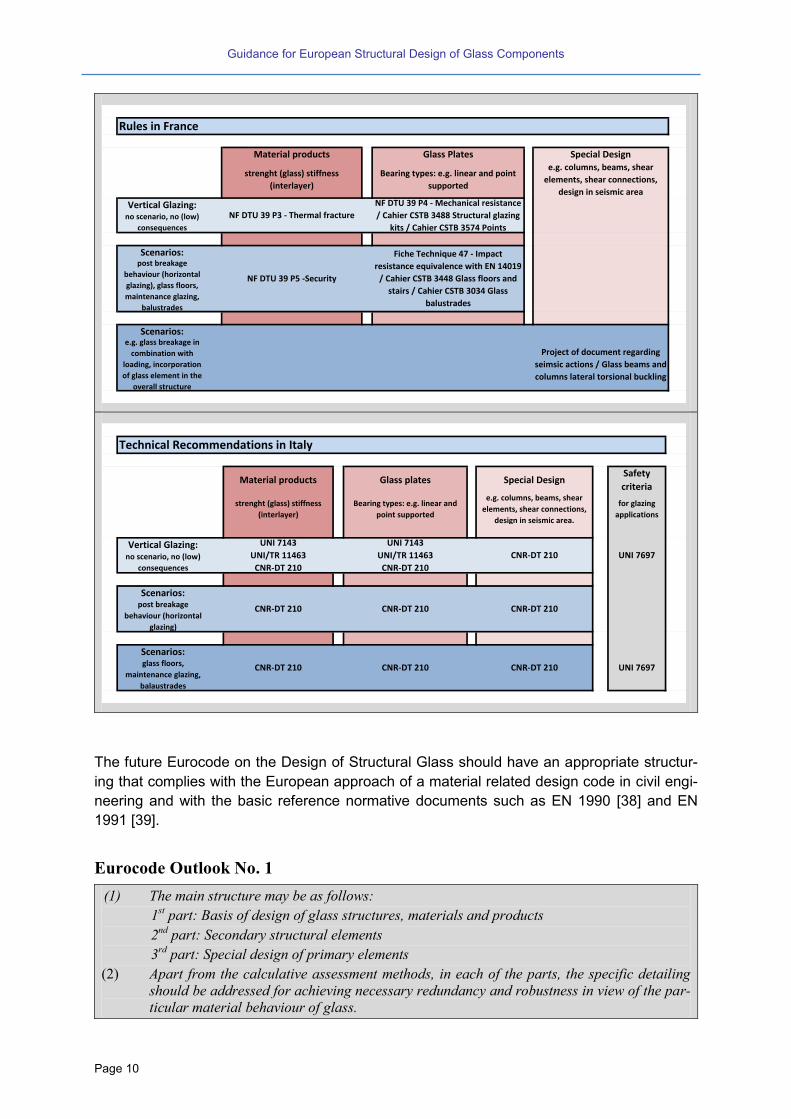
Code Review No. 1
The review on existing national codes for some member states is shown in the following figures (no
claim to be complete).
Material products Glass Plates Special Design
strenght (glass) stiffness
(interlayer)
Bearing types: e.g. linear and point
supported
e.g. columns, beams, shear
elements, shear connections,
design in seismic area
no scenarios DIN 18008-1
Scenarios:post breakage
behaviour (horizontal
glazing)
Scenarios:glass floors,
maintenance glazing,
balustrades
Rules in Germany
DIN 18008-1DIN 18008-1 (linear supported)
DIN 18008-3 (point supported)
DIN 18008-1 DIN 18008-4,-5 and -6
Material products Glass Plates Special Design
strenght (glass) stiffness
(interlayer)
Bearing types: e.g. linear and point
supported
e.g. columns, beams, shear
elements, shear connections,
design in seismic area
no scenarios ÖNORM B 3716-1
Scenarios:post breakage
behaviour (horizontal
glazing)
Scenarios:glass floors,
maintenance glazing,
balustrades
Rules in Austria
ÖNORM B 3716-1ÖNORM B 3716-2 (linear supported)
ÖNORM B 3716-5 (point supported)
ÖNORM B 3716-1 ÖNORM B 3716-3 and -4
Material products Glass Plates Special Design
strenght (glass) stiffness
(interlayer)
Bearing types: e.g. linear and point
supported
e.g. columns, beams, shear
elements, shear connections,
design in seismic area
Scenarios: ČSN 74 3305 Ochranná zabradlí
balustrades
Rules in Czech republic

Guidance for European Structural Design of Glass Components
Page 9
Material products Glass Plates Special Designstrenght (glass) stiffness
(interlayer)
Bearing types: e.g. linear and point
supported
e.g. columns, beams, shear
elements, shear connections
Scenarios: (low) consequences
breakage behavior, all
applications
Scenarios:post breakage
behaviour, all
applications
Scenarios:e.g. glass breakage in
combination with
loading, incorporation
of glass element in the
overall structure
NEN2608
NEN2608 (riks of life)
Dutch regulations
NEN2608
NEN3569 (risk of injury)
Material products Glass Plates Special Design
strength (glass) stiffness
(interlayer)
Bearing types: e.g. linear and point
supported
e.g. columns, beams, shear
elements, shear connections,
design in seismic area
Vertical Glazing: no scenario, no (low)
consequences
CEN TC 129/WG 8 (prEN
13474)
Scenarios:post breakage
behaviour (horizontal
glazing), glass floors,
maintenance glazing,
balustrades
Scenarios:e.g. glass breakage in
combination with
loading, incorporation
of glass element in the
overall structure
Ad-hoc calculations and tests
EN 12600
EN glass product standards
BS 6262-4 safety glass usage
BS 5516 sloping glazing
BS6180 barriers
CWCT TN66, TN67, TN92
None None
British Regulations
EN glass product standardsBS 6262 vertical glazing
Glass & Thermal Safety (Pilkington)
Guidance for European Structural Design of Glass Components
Page 10
The future Eurocode on the Design of Structural Glass should have an appropriate structur-
ing that complies with the European approach of a material related design code in civil engi-
neering and with the basic reference normative documents such as EN 1990 [38] and EN
1991 [39].
Eurocode Outlook No. 1
(1) The main structure may be as follows:
1st part: Basis of design of glass structures, materials and products
2nd
part: Secondary structural elements
3rd
part: Special design of primary elements
(2) Apart from the calculative assessment methods, in each of the parts, the specific detailing
should be addressed for achieving necessary redundancy and robustness in view of the par-
ticular material behaviour of glass.
Material products Glass Plates Special Design
strenght (glass) stiffness
(interlayer)
Bearing types: e.g. linear and point
supported
e.g. columns, beams, shear
elements, shear connections,
design in seismic area
Vertical Glazing: no scenario, no (low)
consequences
Scenarios:post breakage
behaviour (horizontal
glazing), glass floors,
maintenance glazing,
balustrades
Scenarios:e.g. glass breakage in
combination with
loading, incorporation
of glass element in the
overall structure
Project of document regarding
seimsic actions / Glass beams and
columns lateral torsional buckling
Rules in France
NF DTU 39 P3 - Thermal fracture
NF DTU 39 P4 - Mechanical resistance
/ Cahier CSTB 3488 Structural glazing
kits / Cahier CSTB 3574 Points
NF DTU 39 P5 -Security
Fiche Technique 47 - Impact
resistance equivalence with EN 14019
/ Cahier CSTB 3448 Glass floors and
stairs / Cahier CSTB 3034 Glass
balustrades
Material products Glass plates Special DesignSafety
criteria
strenght (glass) stiffness
(interlayer)
Bearing types: e.g. linear and
point supported
e.g. columns, beams, shear
elements, shear connections,
design in seismic area.
for glazing
applications
Vertical Glazing: no scenario, no (low)
consequences
Scenarios:post breakage
behaviour (horizontal
glazing)
Scenarios:glass floors,
maintenance glazing,
balaustrades
UNI 7697
Technical Recommendations in Italy
CNR-DT 210 CNR-DT 210 CNR-DT 210
CNR-DT 210 CNR-DT 210 CNR-DT 210
UNI 7143
UNI/TR 11463
CNR-DT 210
UNI 7143
UNI/TR 11463
CNR-DT 210
CNR-DT 210 UNI 7697
Guidance for European Structural Design of Glass Components
Page 11
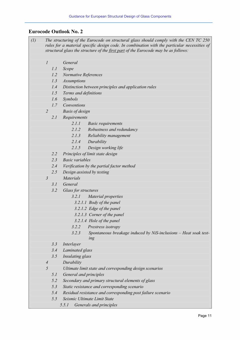
Eurocode Outlook No. 2
(1) The structuring of the Eurocode on structural glass should comply with the CEN TC 250
rules for a material specific design code. In combination with the particular necessities of
structural glass the structure of the first part of the Eurocode may be as follows:
1 General
1.1 Scope
1.2 Normative References
1.3 Assumptions
1.4 Distinction between principles and application rules
1.5 Terms and definitions
1.6 Symbols
1.7 Conventions
2 Basis of design
2.1 Requirements
2.1.1 Basic requirements
2.1.2 Robustness and redundancy
2.1.3 Reliability management
2.1.4 Durability
2.1.5 Design working life
2.2 Principles of limit state design
2.3 Basic variables
2.4 Verification by the partial factor method
2.5 Design assisted by testing
3 Materials
3.1 General
3.2 Glass for structures
3.2.1 Material properties
3.2.1.1 Body of the panel
3.2.1.2 Edge of the panel
3.2.1.3 Corner of the panel
3.2.1.4 Hole of the panel
3.2.2 Prestress isotropy
3.2.3 Spontaneous breakage induced by NiS-inclusions – Heat soak test-
ing
3.3 Interlayer
3.4 Laminated glass
3.5 Insulating glass
4 Durability
5 Ultimate limit state and corresponding design scenarios
5.1 General and principles
5.2 Secondary and primary structural elements of glass
5.3 Static resistance and corresponding scenario
5.4 Residual resistance and corresponding post failure scenario
5.5 Seismic Ultimate Limit State
5.5.1 Generals and principles
Guidance for European Structural Design of Glass Components
Page 12
5.5.2 Additional requirements
5.5.2.1 “Primary” seismic members
5.5.2.2 “Secondary” seismic members
5.5.2.3 Interaction between glass and surrounding structure
6 Serviceability limit state
6.1 General and principals
6.2 Vertical deflections
6.3 Horizontal deflections
6.4 Vibrations
6.5 Seismic Serviceability Limit States
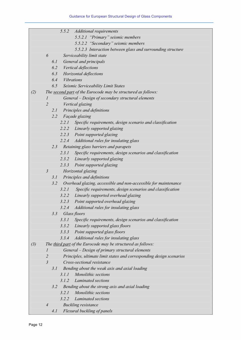
(2) The second part of the Eurocode may be structured as follows:
1 General – Design of secondary structural elements
2 Vertical glazing
2.1 Principles and definitions
2.2 Façade glazing
2.2.1 Specific requirements, design scenario and classification
2.2.2 Linearly supported glazing
2.2.3 Point supported glazing
2.2.4 Additional rules for insulating glass
2.3 Retaining glass barriers and parapets
2.3.1 Specific requirements, design scenarios and classification
2.3.2 Linearly supported glazing
2.3.3 Point supported glazing
3 Horizontal glazing
3.1 Principles and definitions
3.2 Overhead glazing, accessible and non-accessible for maintenance
3.2.1 Specific requirements, design scenarios and classification
3.2.2 Linearly supported overhead glazing
3.2.3 Point supported overhead glazing
3.2.4 Additional rules for insulating glass
3.3 Glass floors
3.3.1 Specific requirements, design scenarios and classification
3.3.2 Linearly supported glass floors
3.3.3 Point supported glass floors
3.3.4 Additional rules for insulating glass
(3) The third part of the Eurocode may be structured as follows:
1 General – Design of primary structural elements
2 Principles, ultimate limit states and corresponding design scenarios
3 Cross-sectional resistance
3.1 Bending about the weak axis and axial loading
3.1.1 Monolithic sections
3.1.2 Laminated sections
3.2 Bending about the strong axis and axial loading
3.2.1 Monolithic sections
3.2.2 Laminated sections
4 Buckling resistance
4.1 Flexural buckling of panels

Guidance for European Structural Design of Glass Components
Page 13
4.1.1 Panels under axial in-plane loads and out of plane loads
4.1.1.1 Monolithic sections
4.1.1.2 Laminated sections
4.1.1.2.1 Uniform loading
4.1.1.2.2 Combined short and long term loading
4.1.2 Combined loading under axial loads and bending
4.1.3 Load introduction and bearings
4.2 Lateral torsional buckling of in-plane-loaded panels
4.2.1 Monolithic sections
4.2.2 Laminated sections
4.2.2.1 Uniform loading
4.2.2.2 Combined short term and long term loading
4.2.3 Load introduction and bearings
4.3 Shear plate buckling of combined in-plane and out-of-plane loaded panels
4.3.1 In-plane corner loaded panels
4.3.1.1 Monolithic sections
4.3.1.2 Laminated sections
4.3.1.2.1 Uniform loading
4.3.1.2.2 Combined short and long term loading
4.3.1.3 Load introduction and bearings
4.3.2 Continuously edge supported panels
4.3.2.1 Monolithic sections
4.3.2.2 Laminated sections
4.3.2.2.1 Uniform loading
4.3.2.2.2 Combined short and long term loading
4.3.2.3 Load introduction and bearings
5 Joints and Connections
5.1 Bolts in shear
5.2 Friction joints
5.3 Adhesive bonding
5.4 Connections for earthquake resistance
6 Design in seismic areas
In the following this report describes first the material properties of glass and interlayers
(chapter 2). Only properties in view of structural applications are discussed, further physical
and/or chemical properties are disregarded within the scope of this report. The mechanical
background, the safety approaches as well as its explication in the different design situations
are presented.
Thereafter different glass products are introduced (chapter 3), before design rules and safety
requirements are described (chapter 4). The mechanical basics of the element plate with
monolithic and laminated section are given in chapter 5.
Secondary and primary structural elements are described separately in chapters 6 and 7. At
the end chapter 8 is dealing with connection types.

Guidance for European Structural Design of Glass Components
Page 14
The grey boxes have two functions. First, the “Codes Reviews” give an overview on the ex-
isting codes like design or product standards. There give an idea about the state of the tech-
nology for the products and the applications. The information does not claim for complete-
ness. Second, the “Eurocode Outlooks” predefine the needed standardisation tasks for the
future Eurocode.

Guidance for European Structural Design of Glass Components
Page 15
2 Material properties
2.1 Glass
2.1.1 General
The following explanations mostly refer to those properties that are important in view of the
load carrying capacity and the durability of structural glass. Other properties like e.g. trans-
mission values, effects of coatings, insulation values of windows are assumed to be not rele-
vant in combination with a Eurocode for the design of structural glass. Further references to
the material characteristics can be found in [96].
2.1.2 Characteristics of annealed glass
In its rigid state, glass can be regarded as an “amorphous solid”. Because of this the me-
chanical behaviour of glass is very brittle without any plastic deformation capacity. Under
loading the strain response to the stress is perfectly linear with sudden failure.
Figure 2-1 Stress-strain relation of glass and steel
Based on physical calculations the theoretical tensile strength results into 5000 MPa up to
8000 MPa. However due to structural defects on the surface (Griffith flaws) the real strength
is much lower. Since high stress concentrations occurring in the cracks cannot be redistrib-
uted because of the lack of ductility, the bending strength of annealed glass in reality reduces
to about 30 – 80 MPa. Depending on the size of the surface crack the bending tensile
strength is controlled by the onset of a hypercritical crack growth without any plastic defor-
mations. This results into a sudden breakage of the glass. On the other hand subcritical
crack growth occurs due to potential so-called stress corrosion under expositions like water
or humidity together with long-term loading. That is the reason why the bending strength of
annealed glass e.g. due to permanent loads is lower than for loads with a short duration.
The bending strength of a float glass panel depends on a variety of influencing factors; the
following gives an overview:

Guidance for European Structural Design of Glass Components
Page 16
Size of the crack: By fracture mechanics the relation between the size of the crack and the
stresses due to external strains can be described. Thereby the surface damage of the glass
is assumed to be dependent on the age of the panel (by which the size and frequency of the
crack is growing). For mode the crack depth is related to the stress concentration factor
:
1
MY
Ka
2
kc
cI
.all
(2-1)
with
crack geometry factor
body geometry factor
tension stresses on the surface of the body
Surface side of the glass panel: According to which of the two surface sides is considered
the bending strength of the two float panel surfaces of freshly produced float glass is differ-
ent. Namely the “tin”-side, having been in contact with the liquid tin bath during production,
provides a lower bending strength compared to the other side that has been exposed to the
air. This may be due to the atomic diffusion of tin or, more likely, due to the contact with the
transport rollers. However this difference between the strength of the two surfaces disap-
pears quickly when glass is in use.
Figure 2-2 Weibull distribution of the bending strength related to the gas- and the tin-side (freshly produced float glass) [108]
Guidance for European Structural Design of Glass Components
Page 17
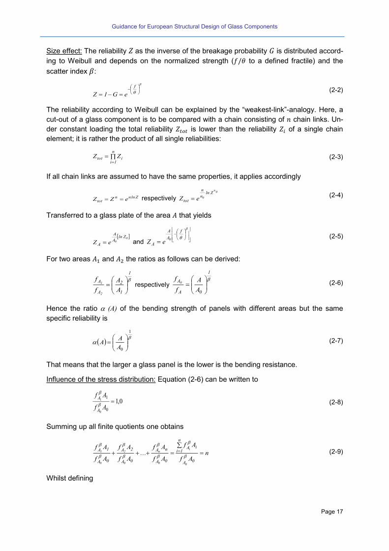
Size effect: The reliability as the inverse of the breakage probability is distributed accord-
ing to Weibull and depends on the normalized strength ( to a defined fractile) and the
scatter index :
f
eG1Z (2-2)
The reliability according to Weibull can be explained by the “weakest-link”-analogy. Here, a
cut-out of a glass component is to be compared with a chain consisting of chain links. Un-
der constant loading the total reliability is lower than the reliability of a single chain
element; it is rather the product of all single reliabilities:
n
1iitot ZZ (2-3)
If all chain links are assumed to have the same properties, it applies accordingly
Zlnnntot eZZ respectively
0n
0
Zlnn
n
tot eZ (2-4)
Transferred to a glass plate of the area that yields
00
ZlnA
A
A eZ and
f
A
A
A0
eZ
(2-5)
For two areas and the ratios as follows can be derived:
1
1
2
A
A
A
A
f
f
2
1
respectively
1
0A
A
A
A
f
f0
(2-6)
Hence the ratio (A) of the bending strength of panels with different areas but the same
specific reliability is
1
0
A
AA
(2-7)
That means that the larger a glass panel is the lower is the bending resistance.
Influence of the stress distribution: Equation (2-6) can be written to
0,10
1
0
1 Af
Af
A
A
(2-8)
Summing up all finite quotients one obtains
nAf
Af
Af
Af...
Af
Af
Af
Af
0A
n
1iiA
0A
nA
0A
2A
0A
1A
0
i
0
n
0
2
0
1
(2-9)
Whilst defining

Guidance for European Structural Design of Glass Components
Page 18
AAAnA ges
n
1ii0
(2-10)
the equivalent strength fA,eq of an area with partial areas that are loaded by uniform
stress can be compared to the equivalent strength fA,eq of the same area but loaded with non-
uniform stress. However both should have the same maximum bending stress max. The
equivalent strength fA,eq then:
max
1
1, )(:
p
A
Af
f
i
n
i
Ai
eqA respectively
1
A
dAAp
max
(2-11)
Influence of the load duration: The ratio of the reference strength f0,A0 coming from a refer-
ence test (with defined load duration, exposition and reference area) to the equivalent refer-
ence strength feq (with different load duration, exposition and reference area) is:
)A(tS
tS
f
f
VV
00
n
A,0
V,eq
0
(2-12)
with
S, n constants of subcritical crack propagation [86] whereby S0 is evaluated under stand-
ardised conditions and SV under current conditions
t0 reference time period
tV current time period
tV(A) = tV (A), see (2-7).
The damage accumulation law according to Miner’s rule can be adopted:
n
V
Vn
veqV
eqtS
AtS
1
00
, )(
(2-13)
and the factor for the time duration can be written:
n
1
00
VVV
tS
)A(tS
)t(
(2-14)
As simplification of (t) the formula for the modification factor is given in [45] taking into
account the load duration can be determined from (2-15) by assuming a constant sur-
rounding medium ( ) and a current time period of 5 sec (related to fracture tests), see
Code Review No. 2:
n/1n/1
0
vmod
t
sec5
t
)A(tk)t(
(2-15)

Guidance for European Structural Design of Glass Components
Page 19
Code Review No. 2
Design standards:
NEN 2608 [45]:
Factor of load duration
c/1
modt
5k
t: load duration in seconds; kmod,min = 0,25, kmod,max = 1, c: constant of corrosion, for all edge zone c
= 16; no edge zone and surface of laminated glass adjacent to the interlayer c = 18; no edge zone
and surface adjacent to a hermetical sealed cavity, the humidity in the cavity is at maximum 10% c
= 27; no edge zone and other situations c = 16
prEN 16612 [37]: Factor of load duration 16/1
mod t663,0k with factor of corrosion c = 16, t in
[h]
CNR-DT-210 [55]: The Italian CNR-DT-210, suggests the expression 16/1mod t585,0k .
The types of loading are connected with specified load duration. The specification of the load dura-
tions are not unified in the different countries, see
Code Review No. 25 et seq..
Load dura-
tion
Type of loading and kmod
[44]
Type of loading and
kmod [48]
Type of loading and kmod [37]
Permanent Permanent load and per-
manent climatic loading
(pH) 0,25
Permanent load and
climatic load
0,6
Dead load, self-weight
0,29
middle Climatic loading (pT and
(ppmet)) and snow
0,4
Snow, personnel
loading on glass
floors and driveable
floors
0,6
Yearly temperature variation
0,39
Snow 0,44
Barometric pressure 0,5
Daily temperature variation
0,57
short Horizontal traffic load
and wind [44]
0,7
Horizontal traffic
load, maintenance
load and wind
0,7
Wind (short, multiple) 0,7
Personnel loads (short, single
gust( 0,89
Wind (single gust) 1,0
0
0,2
0,4
0,6
0,8
1
1,2
1,4
1,6
0,001 0,1 10 1000
k m
od
[-]
Time [h]
Factors of load duration kmod
factor of corrosion c = 16
factor of corrosion c = 18
factor of corrosion c = 27

Guidance for European Structural Design of Glass Components
Page 20
Code Review No. 3
Technical recommendation:
The Italian CNR-DT-210 [55] takes into account of the effects of the type of stress (uniaxial, biaxial
etc.). This is because failure is triggered by the growth of a dominant crack in mode I, and the
probability of having a dominant crack at right angle to the principal tensile stress is higher, e.g., if
the state of stress is equibiaxial, rather than uniaxial.
Influence of the exposition: Based on equation (2-12) an exposition factor can be derived:
n1
VVV
VV
V
n
max
Vmax,V
)A(tS
)A(tS)S(
(2-16)
The crack growth rate is related to the stress concentration factor and parameters S and n
are depending on the surrounding. In the literature the following values are given [106].
Table 2-1 Parameter and depending on the surrounding medium
Temperature n S
Defect under water 35 °C 16 5
Humidity 50% 25 °C 18.1 0.45
Humidity 10% 25 °C 27 0.87
Snow 2 °C 16 0.82
Vacuum 70 250
As can be seen the number of parameters influencing the surface bending resistance of an-
nealed glass is relatively large. Particularly the expositions like to sand, dust and water may
strongly influence. Since the parameters in Table 2-1 are depending on the chemical glass
composition, they have to be considered in the product codes. However the national regula-
tions are dealing with them differently.
The short back of a limited bending strength of annealed glass can – to some extent - be
overcome by thermal pre-stressing. Detrimental exposition effects can be avoided by lami-
nating the load carrying glass layers thus protecting it.
2.1.3 Toughened glass
2.1.3.1 Toughening process
Glass has no crystallisation temperature but a so-called transformation temperature. At high-
er temperatures the state of the glass is changing from an elastic material to a “liquid” with
viscoelastic and at the end to a liquid with viscous properties.
The glass melt consisting of sand, quartz and soda has a temperature of about 1100-
1200°C. For the post-processing of glass the so-called glass transformation temperature
(about 650°C) is important. Around that transformation temperature range the material prop-
Guidance for European Structural Design of Glass Components
Page 21
erties are viscoelastic. These properties are used to induce residual stresses in the glass by
heating up the glass panel up to 650° and cooling down very fast.
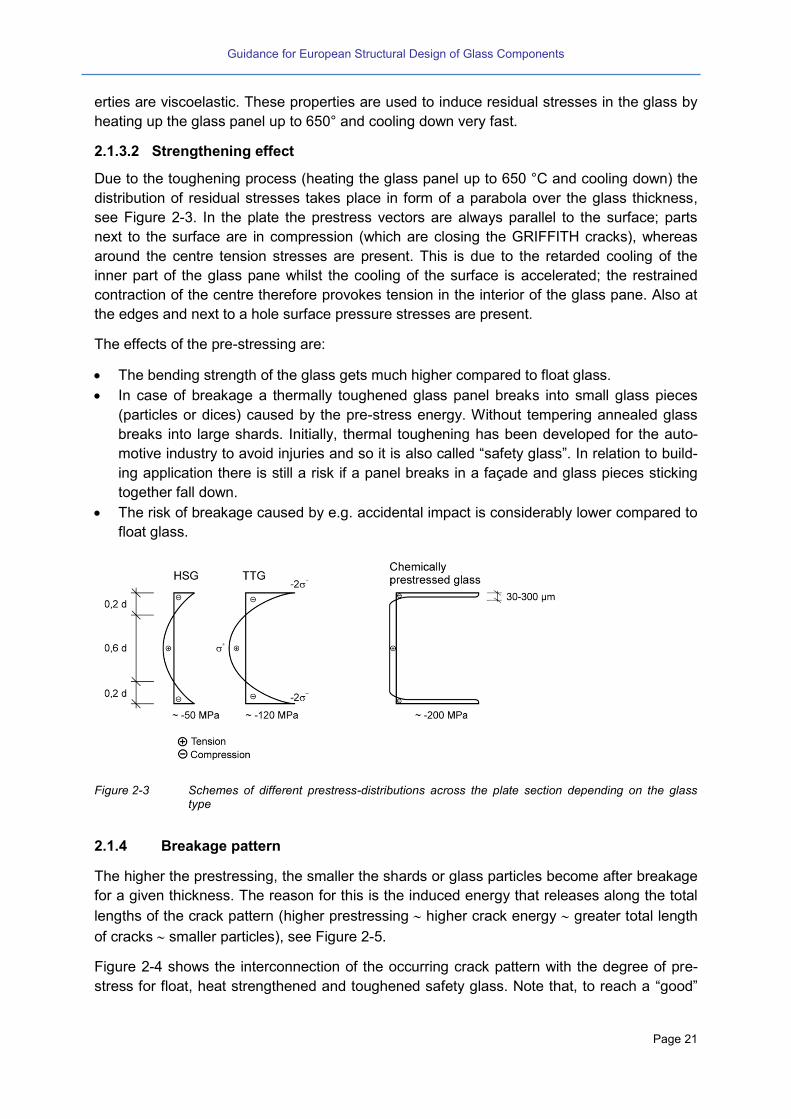
2.1.3.2 Strengthening effect
Due to the toughening process (heating the glass panel up to 650 °C and cooling down) the
distribution of residual stresses takes place in form of a parabola over the glass thickness,
see Figure 2-3. In the plate the prestress vectors are always parallel to the surface; parts
next to the surface are in compression (which are closing the GRIFFITH cracks), whereas
around the centre tension stresses are present. This is due to the retarded cooling of the
inner part of the glass pane whilst the cooling of the surface is accelerated; the restrained
contraction of the centre therefore provokes tension in the interior of the glass pane. Also at
the edges and next to a hole surface pressure stresses are present.
The effects of the pre-stressing are:
The bending strength of the glass gets much higher compared to float glass.
In case of breakage a thermally toughened glass panel breaks into small glass pieces
(particles or dices) caused by the pre-stress energy. Without tempering annealed glass
breaks into large shards. Initially, thermal toughening has been developed for the auto-
motive industry to avoid injuries and so it is also called “safety glass”. In relation to build-
ing application there is still a risk if a panel breaks in a façade and glass pieces sticking
together fall down.
The risk of breakage caused by e.g. accidental impact is considerably lower compared to
float glass.
Figure 2-3 Schemes of different prestress-distributions across the plate section depending on the glass type
2.1.4 Breakage pattern
The higher the prestressing, the smaller the shards or glass particles become after breakage
for a given thickness. The reason for this is the induced energy that releases along the total
lengths of the crack pattern (higher prestressing higher crack energy greater total length
of cracks smaller particles), see Figure 2-5.
Figure 2-4 shows the interconnection of the occurring crack pattern with the degree of pre-
stress for float, heat strengthened and toughened safety glass. Note that, to reach a “good”

Guidance for European Structural Design of Glass Components
Page 22
crack pattern for heat strengthened glass as for float, no (or only a few) “island-shards”
should occur.
Only some are specified destructive methods exist to determine the bending strength as well
as the quantity and homogeneity of the pre-stressing. In such a test a small glass plate (360
mm x 1100 mm) is to be destroyed under a loading-free situation. Depending on the product
(heat strengthened or thermally toughened glass) specified criteria have to be fulfilled e.g. a
minimum number of broken glass particles.
Annealed glass / float glass Heat strengthened glass
(HSG) Thermally toughened
glass (TTG)
Characteristic bending
strength 45 N/mm² 70 N/mm² 120 N/mm²
Detail “breakage struc-ture” (near to the edge)
Degree of surface pre-stress
0 MPa 30-50 MPa > 90 MPa
Figure 2-4 Interconnection of the occurring crack pattern with the degree of prestress for float, heat strengthened and toughened safety glass
Figure 2-5 Size of the glass splinters depending on the level of prestressing [111]
Code Review No. 4

Guidance for European Structural Design of Glass Components
Page 23
Product standard:
EN 12150-1 [11]: The number of glass pieces in a square of 50 mm x 50 mm is an indicator for the
quality of a thermally toughened glass panel. The higher the induced stresses are the higher the
number of glass pieces is.
EN 1863 [10]: Heat strengthened glass should have a breakage structure similar to float glass. The
number and size of so-called “island” pieces like No.1 or 2 is limited in the product standard.
Technical Approvals, Building regulations:
In Germany, the glass producers control also the breakage structure of glass panels up to the larg-
est producible format of heat strengthened or thermally toughened glass panels, because the validi-
ty of the small scale tests is limited [47].
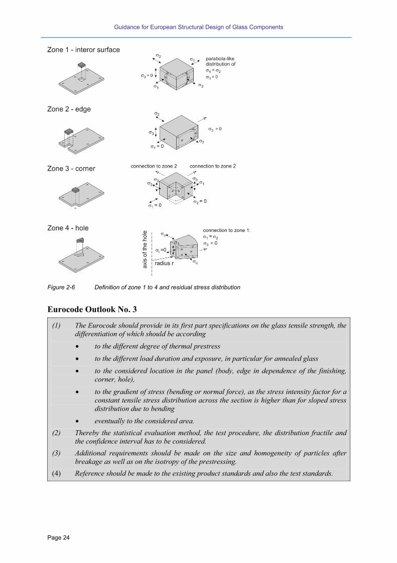
2.1.5 Definition of the zones 1 to 4
When speaking of “strength”, the bending strength is meant. However it is known that in a
glass panel the bending strength differs significantly depending on the position where it is
obtained. In view of these four characteristic zones are distinguished: the interior or body
zone (zone 1), the edge of the panel (zone 2), the corner strength (zone 3) and the edge of a
hole (zone 4).
Guidance for European Structural Design of Glass Components
Page 24
Figure 2-6 Definition of zone 1 to 4 and residual stress distribution
Eurocode Outlook No. 3
(1) The Eurocode should provide in its first part specifications on the glass tensile strength, the
differentiation of which should be according
to the different degree of thermal prestress
to the different load duration and exposure, in particular for annealed glass
to the considered location in the panel (body, edge in dependence of the finishing,
corner, hole),
to the gradient of stress (bending or normal force), as the stress intensity factor for a
constant tensile stress distribution across the section is higher than for sloped stress
distribution due to bending
eventually to the considered area.
(2) Thereby the statistical evaluation method, the test procedure, the distribution fractile and
the confidence interval has to be considered.
(3) Additional requirements should be made on the size and homogeneity of particles after
breakage as well as on the isotropy of the prestressing.
(4) Reference should be made to the existing product standards and also the test standards.

Guidance for European Structural Design of Glass Components
Page 25
2.1.6 Test methods according to EN 1288
However, the recent European standards define only the bending strength of zone 1 (body)
and zone 2 (edge).
Code Review No. 5
Test standard:
EN 1288 [20]: Determination of the bending strength of glass
EN 1288-1: Fundamentals of testing glass:
Definition of the terms:
effective bending strength =average value taken into account the nonuniform stress distribu-
tion
bending strength = bending strength that induce the break of the test specimen
equivalent bending strength : bending strength e .g. of patterned glass
EN 1288-2: Coaxial double ring test on flat specimens with large surface areas:
This test method is only applicable for flat glass. Depending on the thickness tolerances also pat-
terned glass can be tested.
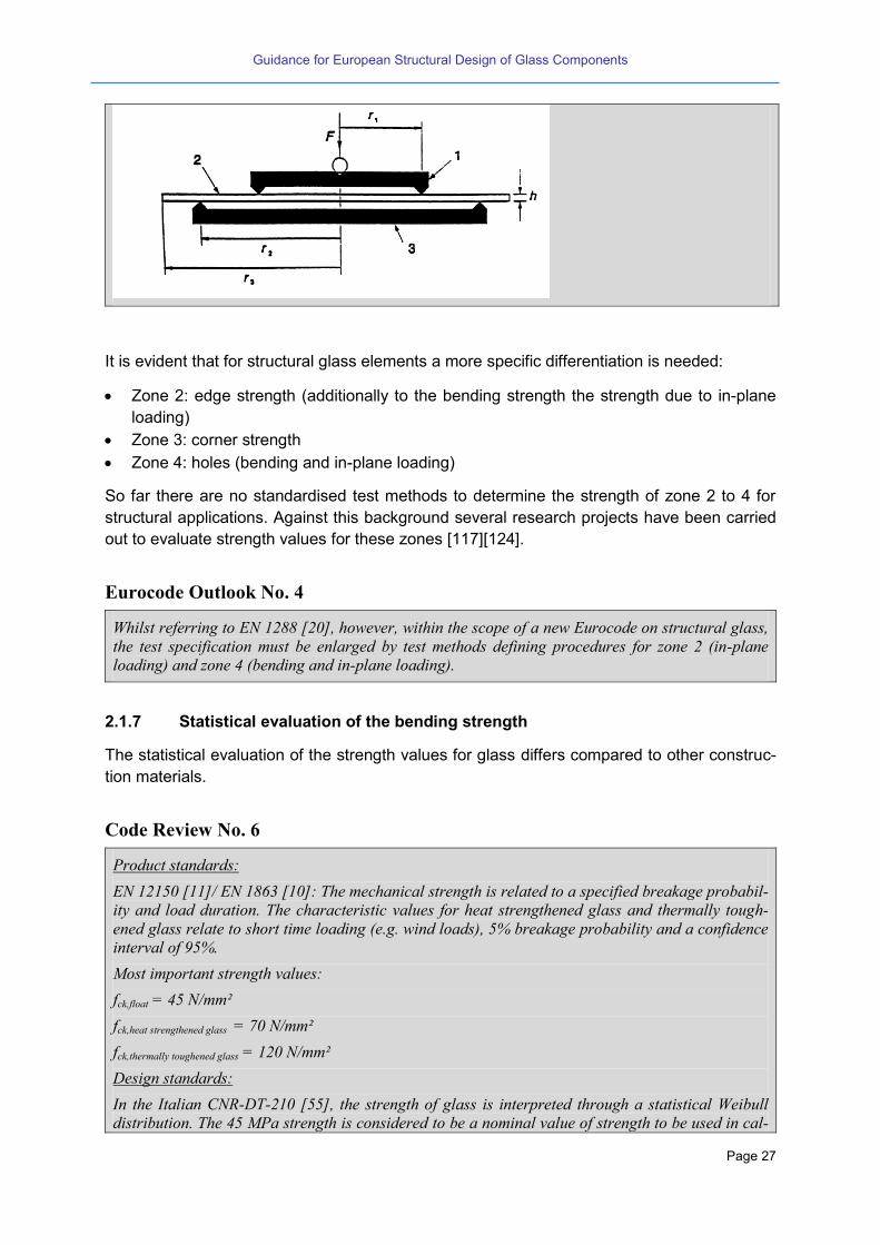
The coaxial double ring test avoids the influence of the edges. In the case of small deflection and p =
0 a coaxial stress situation is present in the circle with the radius r1. In the case of large deflections
local stress concentrations occur under the circular pressure ring. This can be avoided by a com-
bined ring and pressure load F + p. A nonlinear evaluation method is given in the test standard to
evaluate the failure strength.
The stress rate during test should be 2 ± 0,4 N/mm².

Guidance for European Structural Design of Glass Components
Page 26
p: pressure, F: load, r1 = 300 ± 1 mm, r2 = 400 ± 1 mm, L = 1000 ± 4 mm
EN 1288-3: Test with specimen supported at two points (four point bending):
This test method is only applicable for flat glass. Patterned glass can be tested without restrictions.
The test results are influenced by the bending strength of the edges. For slender test specimen the
evaluation of the results can be done by the linear beam theory. In the case of large test specimen
the Poisson effect has to be taken into account. The Poisson effect evokes a stress concentration
near to the edges and a discharging of the inner part. The strength can be evaluated from all broken
test specimen or only from “edge breaks”.
The stress rate during test should be 2 ± 0,4 N/mm².
Lb = 200 mm, Ls = 1000 mm
EN 1288-5: Coaxial double ring test on flat specimens with small test surface areas:
This test method is only applicable for flat glass. Patterned glass cannot be tested.
The advantage is the coaxial loading of the glass panel, but the bending strength is up 300% higher
compared to the methods in part 2 or 3.
Guidance for European Structural Design of Glass Components
Page 27
It is evident that for structural glass elements a more specific differentiation is needed:
Zone 2: edge strength (additionally to the bending strength the strength due to in-plane
loading)
Zone 3: corner strength
Zone 4: holes (bending and in-plane loading)
So far there are no standardised test methods to determine the strength of zone 2 to 4 for
structural applications. Against this background several research projects have been carried
out to evaluate strength values for these zones [117][124].
Eurocode Outlook No. 4
Whilst referring to EN 1288 [20], however, within the scope of a new Eurocode on structural glass,
the test specification must be enlarged by test methods defining procedures for zone 2 (in-plane
loading) and zone 4 (bending and in-plane loading).
2.1.7 Statistical evaluation of the bending strength
The statistical evaluation of the strength values for glass differs compared to other construc-
tion materials.
Code Review No. 6
Product standards:
EN 12150 [11]/ EN 1863 [10]: The mechanical strength is related to a specified breakage probabil-
ity and load duration. The characteristic values for heat strengthened glass and thermally tough-
ened glass relate to short time loading (e.g. wind loads), 5% breakage probability and a confidence
interval of 95%.
Most important strength values:
fck,float = 45 N/mm²
fck,heat strengthened glass = 70 N/mm²
fck,thermally toughened glass = 120 N/mm²
Design standards:
In the Italian CNR-DT-210 [55], the strength of glass is interpreted through a statistical Weibull
distribution. The 45 MPa strength is considered to be a nominal value of strength to be used in cal-
Guidance for European Structural Design of Glass Components
Page 28
culations. Material partial safety factors are calculated on the basis of full probabilistic (level III)
methods for paradigmatic cases.
Code Review No. 7
Technical approval:
In the technical approval for channel shaped glass [74][75], in contrast to flat glass in EN 12150
[11] /EN 1863 [10], the profile bending strength is to be evaluated with a 5% breakage probability
and a confidence interval of 75% according to EN 1990 [38].
Eurocode Outlook No. 5
(1) The Eurocode should specify an appropriate statistical evaluation to determine the strength
referring to the corresponding strength distribution in terms of mean value, standard devia-
tion and further of probabilistic approach.
2.1.8 Quality control by non-destructive methods, stress optics
Non-destructive quality control of tempered glass panels (TTG and HSG) can be carried out
with the use of optical devices. Here, is to differentiate between methods that locally meas-
ure the amount of stress and on the other hand methods that visualise the qualitative homo-
geneity or isotropy of the pre-stress over the plate.
The local methods take account of the birefringence effect of glass, the qualitative methods
are based on light polarisation effects and their visualisation techniques.
The measurements taken using these methods are found to be operator dependent and not
easily repeatable even by the same operator. Therefore any measurements using these
methods should only be taken as general qualitative indicators and not as quantitative values
for design or glass selection purposes.
2.2 Interlayer
2.2.1 General
In general, interlayers are of polymer or ionomer materials. They show a significant time- and
temperature dependency. This characteristic is also influencing the static behaviour of glass
laminates under different loading situations. Some basics concerning the viscoelastic effects,
appropriate testing methods and a design method are described hereafter. Further refer-
ences to the material characteristics can be found in [154] [155] [156].
2.2.2 Viscoelastic behaviour of interlayers
There are various investigations on the creep and relaxation behaviour of the interlayer,
mostly of PVB, in laminated glass panels, all of them using different test setups, evaluation
and interpretation techniques. As a result the proposed time dependent shear moduli accord-
ing to different authors are different [150] [159] [160] [161] [162] [163].
Guidance for European Structural Design of Glass Components
Page 29
Differences may be reasoned by the different test setup, different sizes and theoretical ap-
proaches. However there is the need on having a reliable elasticity-time-law to benefit from
the composite effect of laminated glass, in particular ionomer interlayers.
2.2.3 Determination of the viscoelastic behaviour with “small size” tests
Generally, mechanical tests are performed with methods that apply at specific ranges of time
domain depending on the load time that is necessary to investigate. The frequency of dy-
namic action in engineering analysis generally ranges from 10-9 to 100 Hz. Higher frequen-
cies are useful in the study of impacts and explosions. The most common test methods that
are able to determine the rheological properties of polymer materials are reported in the fol-
lowing.
Transient experiments
Typical transient experiments are ”creep” and “stress” relaxation. In a creep experiment, a
constant stress is applied to a specimen and the corresponding strain is recorded as a func-
tion of time; using this procedure, the creep compliance is obtained. On the other hand, in a
stress relaxation experiment, a constant strain is imposed to a specimen and the correspond-
ing stress is determined, thus obtaining the shear relaxation modulus.
Periodic experiments
If stress (or strain) applied on a viscoelastic material is varied periodically with sinusoidal law,
the strain (or stress) will also alternate with the same law and frequency, but the course will
be out of phase. In case of sufficiently small deformations, material functions such as relaxa-
tion modulus or creep compliance are independent on the amplitude of strain or stress ap-
plied to the specimen. These conditions are satisfied in the linear viscoelastic range. If, at a
given temperature, a strain is imposed according to
ωtsinγγ 0 (2-17)
It can be easily shown [110] that, in the linear range, the stress can be expressed as:
t)(cosGt)sin(G0 (2-18)
where the shear storage modulus and the shear loss modulus of the material
are functions of the angular frequency only. If stress is applied according to a sinusoidal
time law, the same definitions can be set up for the creep functions. This test method, re-
ferred to as “forced vibrations”, applies at a frequency range of 10-2 to 102 Hz.
Among the periodic experiments, the free oscillation (for example, torsional oscillation) co-
vers in general a frequency range of 0.01 to 25 Hz, the upper limit being set by the dimen-
sions of the specimen when becoming comparable to the wavelength of the stress waves in
the specimen. The viscoelastic properties are obtained from the value of the constant angu-
lar frequency of the specimen and the gradually decreasing amplitude of the oscillation. At
higher frequencies, the wavelength of displacement becomes too short with respect to the
dimensions of specimen; in such cases, the propagation of travelling waves can be observed
and the velocity and the attenuation of waves provides the components of the complex
Young’s modulus. Longitudinal and flexural waves in thin strips can cover in general a fre-
quency range from the order of 102 to 107 Hz.
Guidance for European Structural Design of Glass Components
Page 30
Given a certain frequency , different values of and can be found if periodic
tests are performed at different temperatures. It was observed that, if one represents
[110]. A general form for the description of the shift value as a function of , com-
monly accepted in the analysis of polymers, was proposed by William Landel and Ferry
(WLF equation):
0
02
001
TTTc
)TT(calog
(2-19)
Once the mathematical constants and
have been determined, obtaining from superpo-
sition of experimental points determined at various temperatures, it is possible to build the
master curve at the reference temperature for the viscoelastic constants and to represent
master curves for different reference temperatures.
Code Review No. 8
Test standard:
prEN 16613 [22]: differentiation of isotropic and non-isotropic interlayer materials
Test methods: dynamic shear test method and bending tests
Determination of:
Glass transition temperature
Stiffness depending on a range of frequencies and a range of temperature
Master curve and WLF-Parameters
Definition of stiffness families
Derivation of the shear transfer coefficient to calculate an effective thickness of a glass
laminate
2.2.4 Determination of the viscoelastic behaviour in the panel-torsion-test
With these existing “small size”-tests the time and temperature dependent stiffness behav-
iour of interlayers can be determined. However they show some shortcomings in view of the
size-effect. Therefore, in the following a “large-size-test” in form of a panel-torsional-test is
described. A further possibility is a four-point-bending test. They are suited in particular since
herewith large panels with real geometrics can be investigated. Because the composite area
of the interlayer is large enough, influences from the edges are minimized. The test methods
give good results for interlayer materials with a shear stiffness < 10 MPa.
By means of the so-called panel-torsion-test [166] [167] [169] the time and temperature de-
pendent mechanical behaviour of laminated glass panels can be well observed. Further to
the fact that it minimizes effects from edges it also takes into account the bonded glass sur-
face (substrate) which expectedly may change the mechanical behaviour compared to that
obtained from pure interlayer.

Guidance for European Structural Design of Glass Components
Page 31
Figure 2-7 Test set-up and measurement devices at the panel-torsion-test
In the test setup the laminated panels are friction-free clamped at the two ends. This will be
realized by two steel sections positioned to a “fork” at each end. To avoid friction as far as
possible; the contact planes of the section flanges are covered with PTFE-layers (Teflon).
One pair of steel sections is fixed rigid to the lower structure, whereas the other is turnable
about a rotation axis. At the turnable side the load introduction as well as the load- and the
rotation-measurement (twist measurement by an inclinometer) are positioned. With the
PTFE-layers avoiding friction, the small shift of the longitudinal axis of the panels against the
turning axis of the apparatus does not produce an additional constraint and thus can be ne-
glected.
Also to test the temperature influences, the whole set-up can be conducted in a climate
chamber.
Test-specimens can be laminated glass panels with ambiguous glass compositions. The
dimensions should be 1100 mm x 360 mm or larger. Either the rotation is kept constant and
the relaxing twist-moment is measured or, inversely, the twist moment is kept constant and
the creeping rotation angle is going to be measured. Evaluations of some tests on 2 x 6 mm
HSG respectively 2 x 5 mm HSG with each 1.52 mm thick PVB are shown in Figure 2-9.

Guidance for European Structural Design of Glass Components
Page 32
Figure 2-8 Relaxation- and creep-history as well as the respective development of the shear modulus from the panel-torsion-tests of laminated glass panes with PVB, = 23 °C
The shear modulus and the stresses can be determined either according to the extended
bending and torsion theory or according to the “sandwich theory with torsion” [166] [167].
Solving the differential equation according to the first mentioned theory:
,
~11
1
22211
212
11 TS
S
S
I eqT
(2-20)
using the coefficients according to Table 2-2. Alternatively the equivalent torsional stiffness
can be derived by the sandwich theory:
2
2tanh12
3
2 23
B
BdtdBdBI
T
TeqT
(2-21)
with dtG
GFT
22 (2-22)
0
0,05
0,1
0,15
0,2
0,25
0,3
0,35
0 200 400 600 800 1000 1200 1400 1600 1800
sh
ea
r s
tre
ss
es
[N
/mm
²]
loading time [s]
0
1
2
3
4
5
6
7
0 200 400 600 800 1000 1200 1400 1600 1800
[°
]
loading time [s]
0,0
0,5
1,0
1,5
2,0
2,5
3,0
0 200 400 600 800 1000 1200 1400 1600 1800
sh
ea
r m
od
ulu
s G
F[N
/mm
²]
loading time [s]
0,0
0,5
1,0
1,5
2,0
2,5
3,0
0 200 400 600 800 1000 1200 1400 1600 1800
sh
ear
mo
du
lus G
F[N
/mm
²]
loading time [s]

Guidance for European Structural Design of Glass Components
Page 33
Table 2-2 Coefficients and function 22T~
for torsion
Laminated glass with two equal layers
11S
33
2
1
2
1
3
8tdtB
22S
dB 2
1
12S
22
2
1
2
1tdtB
22,S t
B3
12
1
22
~T
22,2211
212
SG
GS
S
S F
The results of (2-20) and (2-21) are only slightly differing, see Figure 2-9.
Figure 2-9 Comparison of the equivalent torsional stiffness according to (2-20) and to (2-21) for different modulus of shear
2.2.5 Durability of PVB interlayer
In [161] it is shown that moisture penetration of a PVB-interlayer at the edge zones of lami-
nated safety glass (LSG) is the only major influencing factor on the durability: hence, shear
behaviour and adhesion characteristics change. Other, neither a significant endangering of
structural safety nor a change in load-carrying behaviour has an only local deterioration of
the interlayer of large-scale architectural LSG panes.
In order to avoid visual damages of LSG (whitening or delamination of interlayer) in outdoor
applications, it is recommended to protect edges thoroughly and effectively (e.g. canopy with
stepped LSG), or generally avoid water access resp. penetration.
0
20
40
60
80
100
120
0 2 4 6 8 10
tors
ion
al s
tiff
ne
ss
ITe
q[c
m4]
shear modulus GF [N/mm²]
extended technical bending and torsional theorysandwich theory
B=500 mmt=1,52 mm
d=10 mm
d=8 mm
d=6 mm0
5
10
15
20
25
30
35
0 2 4 6 8 10
tors
ion
al s
tiff
ne
ss
ITe
q[c
m4]
shear modulus GF [N/mm²]
extended technical bending and torsional theorysandwich theory
B=250 mmt=1,52 mm d=10 mm
d=8 mm
d=6 mm
Guidance for European Structural Design of Glass Components
Page 34
With respect to structural elements under high compressive loading (e.g. columns) delamina-
tion could be significant due to possible instabilities (e.g. local buckling). For glass construc-
tions with point fixings instabilities could not be excluded in case of delamination.
When considering LSG used for photovoltaic applications severe problems with functionality
may occur if moisture concentration exceeds specific values.
Aging of the interlayer due to UV-radiation and temperature is dependent on its intensity and
duration and can mostly be neglected because of high dosage of UV-blocker inside the inter-
layer. Moreover, UV-aging is resulting in a stiffer material behaviour, and therefore not ad-
versely affecting the structural safety.
The assumption of a general aging factor for LSG completely reducing adhesion of glass-
interlayer can be abandoned.
2.2.6 Design shear modulus of PVB- interlayer in dependence of temperature and
time during wind loading
Apart from the pure physical description of the time-dependant viscoelastic behaviour of PVB
layers, there is the question of what value should be used in a static calculation respectively
for the design under combined action. This value should be considered as an effective value,
taking into account the
lower occurrence probability of higher temperatures combined with high wind loading and
exposure time (time period) of wind gust load which is assumed to be sinusoidal.
Whereas in some countries the shear modulus for the PVB layer it is allowed to be taken into
account, at least for short term loading, in other countries this is generally not allowed, even
not for short term wind loading (see Code Review No. 20 and Code Review No. 39). There-
fore, further investigation and knowledge on a safe and at the same time realistic value is
needed.
In [150] [170] it is suggested, to simulate a time- and temperature- dependent distribution of
the effective shear modulus by evaluating the wind load, exposure time of gust and associat-
ed temperature. For this, in a simulation, laminated glass panes with different geometry and
cross-sections are loaded by these spectral values. The 2%- fractile of this distribution can
be regarded as characteristic stress. By evaluating this 2%- fractile of the stress- distribution
of sections with unknown shear modulus but containing information on exposure time and
temperature and equalling this with the 2%- fractile of the spectrum without temperature and
exposure time, then the relevant shear modulus dk GG can be derived.
In Figure 2-10 the correlation of the maximum of exterior air temperatures with the gust wind
velocities for a city in Germany is shown. These evaluations have been performed for a vari-
ety of locations in Germany representing middle Europe. In further investigations it came out,
that the correlation of the temperature of the glass with gust velocity, Figure 2-11, depends
on whether the panel is being weathered from two sides or only from one side, i.e. the other
side is exposed to the interior of a building.

Guidance for European Structural Design of Glass Components
Page 35
Figure 2-10 Correlation of maximum gust wind speed and maximum exterior temperatures for the city of Aachen and overview of other considered locations [150]
Maximal exterior temperature Temperature of the assembly (exterior
temperature on both sides of the as-
sembly)
Temperature of the assembly (exterior
temperature on one side, 23°C on the
other side)
Figure 2-11 Correlation gust - wind load with air- temperature as well as correlation of the gust wind load with the temperature of the structure; interpolated lines are of same occurrence probability, ex-treme values per day in 100 years [150] (Germany)
Using the dependencies of the mean wind velocities respectively the gust factor on the re-
garded interval as shown in Figure 2-11, the wind velocities as well as the wind pressures for
3 seconds, 10 minutes and 24 hours can be determined. Thereby, due to the similarity, the
24 hour interval can be also considered as a 96 hour interval which is regarded to be the
time in which a storm is moving over a geographical location.
s1s1s3 v94,0v56,1
47,1v
s3s3min10 v68,0v47,1
1v
s3s3h24 v48,0v47,1
70,0v
Figure 2-12 Gust factor GB in 10 m height above ground, related to 10 minutes as equalising interval [150]

Guidance for European Structural Design of Glass Components
Page 36
maxs3 qq
maxmax2
min10 q50,0q68,0q
maxmax2
h96h24 q25,0q48,0qq
As a simplification, for each peak wind load incidence also the surrounding longer lasting
wind pressures can be obtained. This is important since for longer exposure times the shear
modulus drops significantly. Using Boltzmann’s law, the so obtained wind pressures can be
introduced into the function of the time dependant shear moduli G(t) so that finally, the
stresses can be calculated. Further considering the relation of glass and air temperature ac-
cording to Figure 2-11, simplified relations of glass-temperature to time and wind load are
obtained, Figure 2-13.
Figure 2-13 Wind load depending on glass temperature and exposure time of the gust [150]
With the correlation according to Figure 2-11 and Figure 2-12, then the bending stresses
vmax, can be calculated. By variation of the sectional composition, colour and geometry a
minimum value for the shear modulus of 2w mm/N4.0G can be obtained.
Using a similar procedure for the load case „snow“ a shear modulus of 2s mm/N6.0G is
obtained [150]. These derivations however are only valid for linear problems, e.g. panels with
transverse loading whereas for nonlinear problems (such as buckling) the values should be
treated with further estimation as to whether the resulting difference is of significance.
An alternative and very simple recommendation shows Figure 2-14. Both for the case “exte-
rior – exterior” as well as for the case “exterior – interior”, show that for ambient exterior tem-
peratures > 25°C, the characteristic wind load drops down to 50% of the maximum character-
istic wind load. Assuming that there is no composite action at temperatures above 25°C, but
a minimum shear modulus of 2mm/N6.0G is up to 25°C active during a three second inter-
val (gust time period), then the following rules may be derived:

Guidance for European Structural Design of Glass Components
Page 37
The laminate can be calculated for 50% of the wind load without composite action and
with a shear modulus of 2mm/N6.0G for 100% of the wind load.
When stability needs to be considered the deflection due to 50% wind load without com-
posite action has to be taken as the initial imperfection (together with the geometrical ec-
centricity) for subsequent calculation of the short term stability effect using the elastic
shear modulus of 2mm/N6.0G .
“Exterior – Exterior” “Interior – Exterior”
Figure 2-14 Temperature- loading curve with 50.0q/q max at C25T
The proposal as presented refers to the limit states considering loading without reversal.
When cyclic loading occurs, further considerations will apply. To expand this to some general
European approach similar correlations should be made in other geographical regions.
Eurocode Outlook No. 6
(1) The Eurocode should include a design concept for laminated glass that takes into account
the different climatic conditions in Europe (correlation of gust-factor and temperature) to
evaluate a safe shear modulus.
(2) The Eurocode should enable transient calculation depending on the viscoelastic behaviour
of the different interlayers taking into consideration thermal effects and load duration in a
mechanically consistent way.

Guidance for European Structural Design of Glass Components
Page 38

Guidance for European Structural Design of Glass Components
Page 39
3 Products
3.1 General
Figure 3-1 shows a chart of the processing steps of the glass production. In the following
chapters the glass products respective process are described and special characteristics are
pointed out.
Eurocode Outlook No. 7
(1) The Eurocode should refer to flat or bent glass in annealed, heat strengthened or thermally
toughened quality.
Figure 3-1 Overview of the most important glass products and the steps of processing

Guidance for European Structural Design of Glass Components
Page 40
3.2 Float glass
3.2.1 General
Float glass, as the most important glass product, is the general material used for windows,
facades, interior glazing and automotive applications. From the basic product it can be pro-
cessed to thermally toughened glass (chapter 3.6), heat strengthened glass (chapter 3.7),
laminated glass (chapter 3.8), curved glass (chapter 3.9) or chemically strengthened glass
(chapter 3.10). The denomination “float glass” originates from the glass process where the
glass melt “floats” on a liquid bed of tin. Meanwhile, the float process is the most common
production technique. Compared to patterned glass (chapter 3.3) the thickness of panels is
constant. Float glass is cooled down very slowly, hence there are only very few residual
stresses induced in the panels (“annealed glass”).
Code Review No. 9
Product standard:
EN 572-2 [2]: The product standard for float glass specifies a bending strength of 45 MPa for zone
1. This value is not a property that the glass has to fulfil but can be regarded as a calculative stress
limit.
German building Regulations [47]:
The characteristic bending strength of 45 MPa must be confirmed by the producer.
3.2.2 Geometrical properties
The material properties are described in chapter 2.1. The maximum dimensions of standard
float glass panels are 3.21 m x 6.0 m [2]. But also larger glass panels can be delivered on
special request. The following nominal thicknesses are generally available:
2, 3, 4, 5 and 6 mm with a tolerance of 0.2 mm
8, 10 and 12 mm with a tolerance of 0.3 mm
15 mm with a tolerance of 0.5 mm and
19 and 25 mm with a tolerance of 1.0 mm.
The production of 25 mm thick glass is very limited due to the costs and manufacturing chal-
lenges.

Guidance for European Structural Design of Glass Components
Page 41
Code Review No. 10
Design codes:
DIN 18008 [44]/NEN 2608 [45]: These design codes deal with individual glass panes of nominal
thicknesses from 3 to 19 mm.
DIN 18008 [44]/ prEN 16612 [37]: The design value of the thickness is the nominal value.
NEN 2608 [45]: The design value of the thickness is the nominal value minus the tolerance.
Eurocode Outlook No. 8
(1) A design value for the thickness should be defined according to EN 1990 [38].
(2) For PV applications the minimum thickness should be reduced to values of 1,5 mm to 2 mm.
3.2.3 Surface processing
The surface properties of float glass depend on different types of processing:
Abrading the surface like polishing, grinding, etching or sandblasting,
Coating like metalizing, printing or enamelling.
In view of structural purposes the surface treatment may have a detrimental effect on the
bending strength of the glass panels.
Code Review No. 11
EN 1096 [8]:
The product standard for coated glass does not give a bending strength depending on the type of
coating.
Eurocode Outlook No. 9
(1) The Eurocode should define if and for which types of coatings a potential strength reduc-
tion can be neglected.
3.2.4 Forming
In advance to processing such as toughening, the glass panes have to be already cut. There
are different types of edge processing.
Code Review No. 12
Product standards:
EN 12150 [11] / EN 1863 [10]:

Guidance for European Structural Design of Glass Components
Page 42
Seamed edge (with blank spots)
Seamed and dressed to size edge (with
blank spots)
Ground edge (without blank spots)
Polished edge
3.3 Patterned glass
The surface of patterned glass is characterised by a special texture being imprinted in the hot
glass. Like float glass patterned glass is annealed. There is a variety of surface patterns
available. Difficulties arise whilst determining a defined thickness. Therefore the nominal
thickness of patterned glass is measured at four points. Hereby, the size of the measurement
device has a diameter of 50±5 mm [5]. Naturally, the thickness tolerances are much higher
compared to float glass. Patterned glass panels can be processed to thermally toughened
glass. Compared to float glass patterned glass is basically used only for non-structural appli-
cations with low failure consequences.
Code Review No. 13
Product standard:
EN 572-5 [5]:
The product standard for patterned glass does not specify a bending strength.
German building Regulations [47]:
The characteristic bending strength of patterned glass is specified to 25 MPa. The value must be
confirmed by the producer.
Guidance for European Structural Design of Glass Components
Page 43
Eurocode Outlook No. 10
(1) The Eurocode should define a method to determine the bending strength of different classes
of patterned glass in consistent manner.
(2) Reference should be made to the existing product standards and also to the test standards.
3.4 Wired glass
Glass can also be produced with a wire netting inside. This product was used as a “safety
glass” in some countries. Its main use is as fire resistance glass. For some application (small
panels) wired glass is being used in other applications, e.g. for monolithic overhead glazing.
Code Review No. 14
Product standard:
EN 572-6 [6]: The product standard for wired patterned glass does not specify a bending strength.
Design Code:
DIN 18008-2 [44]: Linearly supported glazing: Wired patterned glass is allowed for small over-
head glazing with a maximum span of 0,7 m and an edge cover of 15 mm.
Eurocode Outlook No. 11
(1) The Eurocode should define for which temperature difference wired glass can be applied or
give methods to determine glass stresses from temperature loads.
3.5 Drawn sheet glass
Until the 1960ies drawn sheet glass was the standard product for flat glass. Nowadays drawn
sheet glasses are fully replaced by float glasses. This product may still be relevant but only
for renovation projects. Drawn sheet glass can be treated as float glass.
Code Review No. 15
Product standard:
EN 572-4 [4]: The product standard for drawn sheet glass does not specify a bending strength.
3.6 Thermally toughened glass (TTG)
Basic product for thermally toughened glass is float glass or patterned glass. For structural
applications mainly thermally toughened glass made of float glass is used, whereas thermally
toughened patterned glass is used e.g. for solar applications.
The following explanations mainly refer to thermally toughened glass made of float glass.
Caused by the tempering process the surface of thermally toughened glass may become
uneven so that optical warping effects can be observed. This property is not interesting for

Guidance for European Structural Design of Glass Components
Page 44
the structural application but it has to be taken into account when further processing to a lam-
inated section.
Code Review No. 16
Product standard:
EN 12150 [11]: The product standard for thermally toughened glass specifies a characteristic bend-
ing strength of 120 MPa for zone 1.
Thermally toughened glass made of float glass is generally available in the following thick-
nesses: 2, 3, 4, 5, 6, 8, 10, 12, 15, 19 and 25 mm (25 mm is not a standard product). Ther-
mally toughened glass made of patterned glass is produced in thicknesses of 3, 4, 5, 6, 8
and 10 mm.
For architectural applications, thermally toughened 2 mm and 3 mm glass are not standard
product since most architectural grade furnaces do not have sufficient quench power. Newly,
thin pre-stressed glass is used in the middle of triple insulating glass panels to reduce
weight, these panels are pre-stressed, but the level of pre-stressing is often undefined.
If further fabrication procedures are necessary, they generally have to be performed prior to
the tempering process. For instance very important fabrication procedures are:
Drilling the glass panel. Here a minimum distance to the edges, a minimum distance be-
tween the holes (pitch) and a minimum diameter of the respective hole should be consid-
ered.
Edge processing as specified in the product standard.
Code Review No. 17
Product standard:
EN 12150 [11]: The standard for thermally toughened glass gives specifications for the minimum
distance of holes to the edges, the minimum distance to the edges, the minimum diameter and the
minimum distance between two holes. The specifications are dealing with cylindrical holes and are
applied in the scope of manufacturing drilled glass panels.
The diameter of holes, ∅, shall not, in general, be less than the nominal thickness of the glass. For
smaller holes, the manufacturers should be consulted.
In general, the limitations on hole positions relative to the edges of the glass pane, the corners of the
glass pane and to each other depends on: the nominal glass thickness (d); the dimensions of the
pane (B, H); the hole diameter (∅); the shape of the pane and the number of holes.
The recommendations given below are those which are normally available and are limited to panes
with a maximum of 4 holes.

Guidance for European Structural Design of Glass Components
Page 45
The distance, a, of the edge of a hole to the glass
edge should be not less than 2d.
The distance, b, between the edges of two holes
should be not less than 2d.
The distance, c, of the edge of a hole to the cor-
ner of the glass should be not less than 6d.
Design standards:
Design Rules for “loaded” holes can be found in: DIN 18008-3 [44], ÖNORM B 3716-5 [48], NEN
2608 [45]
The characteristic bending strength of thermally toughened glass is given in the product
standard: fk = 120 N/mm² (see Code Review No. 16).
During the tempering process an enamelling can be burned in. The potential detrimental ef-
fect on the bending resistance must be taken into account (therefore for enamelled thermally
toughened glass: fk = 90 N/mm²).
There is a risk of spontaneous breakage of thermally toughened glass due to nickel sulphide
inclusions (NiS) in the glass melt. The reason for NiS-spontaneous fracture is lying in traces
of nickel and sulphur in the glass melt forming inclusions that over time undergo a phase
change and develop an internal local pressure – with the result of breakage. This phenome-
non appears normally during the first ten years after installation of a glass panel, also occur-
rences are known until 20 years after manufacturing. The risk of critical NiS inclusions of float
glass produced in Europe is around 1 in 10 tonnes of glass [116].

Guidance for European Structural Design of Glass Components
Page 46
To minimize the risk of a spontaneous glass breakage toughened glass can be subjected to
a second process, a “heat soak test” to produce heat soaked toughened glass. The risk is
significantly reduced by heat soaking depending on the heating rate and the holding time.
Code Review No. 18
Product standards:
DIN 18516-4 [50]: The product standard for claddings for external walls made of thermally tough-
ened glass specifies a procedure for the heat soak test.
EN 14179-1 [14]: The product standard specifies a heat soaked thermally toughened glass.
National Building Regulations:
E.g. in Germany the “Bauregelliste”(official list of codes and products to be used in construction)
[47] specifies the product ESG-H (heat soaked TSG). The heat soak test procedures differ from the
mentioned product standards.
Design Standards:
NEN 2608 [45]: The Netherland design code demands heat soaked thermally toughened glass for
CC2 applications.
DIN 18008 [44]: The German design codes demand ESG-H e.g. for facades.
Eurocode Outlook No. 12
(1) A harmonized Heat-soak-test under consideration of the recent research results should be
specified in the Eurocode. The application of such a Heat-soak-test should be required for
special secondary elements and for all primary elements. Recent research progress allows
for specification of a relation between the failure probability due to a nickel sulphide inclu-
sion and a Consequence class.
(2) Depending on the application (Photovoltaic or thin insulating glass units) a definition of
different levels of prestress between thermally toughened glass and heat strengthened glass
might be meaningful.
(3) The Eurocode should define which types of enamels lead to the value of 90 MPa.
3.7 Heat strengthened glass (HSG)
Like thermally toughened glass the so-called heat strengthened glass is also pre-stressed
through a thermal treatment. Basically, the level of pre-stressing is significantly lower where-
as the process is more challenging. Heat strengthened glass is intended for glass with a
higher resistance than float but with a breakage structure with large pieces comparable to
annealed glass. The applications are mainly laminated glass panels used for components
with residual resistance requirements and an aspired higher bending strength than float
glass.
Compared to chapter 3.6 above the following points are different:
Heat strengthened glass made of float glass, patterned glass or drawn sheet glass is
produced with a nominal thickness of 2, 3, 4, 5, 6, 8, 10 and 12 mm.
The level of pre-stressing is lower, so the breakage pattern is characterized by relatively
large shards with references to the destructive test of the product standard.
Guidance for European Structural Design of Glass Components
Page 47
The bending strength of heat strengthened glass made of float glass is fk,Zone 1 = 70
N/mm².
There is effectively no significant risk of collapse due to NiS-spontaneous breakage, also
because heat strengthened glass is normally used as a laminated glass.
Code Review No. 19
Product standard:
EN 1863 [10]: The product standard for heat strengthened glass specifies a characteristic bending
strength of 70 MPa for zone 1.
National Building Regulations:
Due to the difficult production process for heat strengthened glass, e.g. in Germany a special Tech-
nical Approval is prescribed.
3.8 Laminated and laminated safety glass
A laminated glass is a combination of two or more glass layers connected with an interlayer
such that the cross section responds mechanically with a composite effect. There are differ-
ent types of interlayers available with various properties (chapter 2.2).
Depending on the composition of the laminated glass the variety of properties is intended for,
e.g.:
Fire resistance
Impact resistance
Acoustic insulation
Burglar glass
For structural glass the following properties are important being fulfilled from laminated safety
glass:
Sticking of broken glass pieces
Limitation of a gap
Residual resistance
Minimisation of the injury risk
Historically the laminated safety glass has been developed for the automotive industry to
avoid injuries in case of accidents. The standard interlayer material so far has been PVB
(polyvinyl butyral) with viscoelastic properties. The stiffness highly depends on the load dura-
tion and the temperature (chapter 2.2), especially at temperatures larger than 25°C the shear
modulus drops drastically. A simple PVB-interlayer has a thickness of 0.38 mm. Normally two
layers (0.76 mm), four layers (1.52 mm) or for special applications six layers (2.28 mm) can
be combined.
Other interlayer materials are also used for various applications, including cast-in-place res-
ins (usually polymethyl methacrylate or polyester), EVA, polyurethane and ionomer.
Ionomer interlayers developed for hurricane glazing, offer further resistance properties of
laminated glass in terms of high shear stiffness and strength, also at temperatures between

Guidance for European Structural Design of Glass Components
Page 48
25°C and 50°C, and thus provides very good residual resistance. Stiffer grades of PVB inter-
layer are now beginning to penetrate the market and some of these products are comparable
in stiffness to the ionomer interlayers – particularly at the lower temperature ranges.
Figure 3-2 Shear modulus depending on the loading time (T = 23°C), left: PVB, right: Ionomer
In terms of the static behaviour of glass components (plates, columns or beams) the stiffness
of the interlayer is important.
Difficulties arise when determining the relevant shear stiffness of the interlayer. The product
standard does not give stiffness values or a harmonised test procedure for the determination
of these different stiffness values (s. chapter 2.2)
It is remarkable that European countries are dealing with the shear stiffness of the interlayer
materials in rather different ways. In some countries there are stiffness values given in the
design code, e.g. for PVB, other countries demand a technical approval for laminated glass,
so that the properties of the interlayers are warranted, and yet others do not allow for entry of
the shear stiffness at all.
Code Review No. 20
Product standard: EN ISO 12543 [13]: No shear modulus is given in the product standard.
Test standard: prEN 16613 [22]: Tests methods for the determination of the shear stiffness are spec-
ified.
Technical approvals: Technical approvals exist with proved shear modulus for PVB and Ionomer
(e.g. [77]).
Design standard, e.g.:
DIN 18008 [44]: In cases of shear bond is favourable, it is not allowed to be taken into account.
However, it must fully be taken into account, if the shear bond is unfavourable. A laminated glass
panel can be assumed as monolithic if a dynamic loading is acting on the panel. A shear bond can
be assumed by using a product with a technical approval.
NEN 2608 [45]: Formulas are given to calculate a shear transfer factor with the “Prony”-series of
PVB.
ÖNORM B 3716 [48]: For short time loading a shear modulus of G = 0,4 N/mm² can be assumed.
For unfavourable shear effects a monolithic behaviour must be assumed. The background to this
0
1
2
3
4
5
0 100 200 300 400 500 600
sh
ear
mo
du
lus G
F[N
/mm
²]
loading time [s]
0
20
40
60
80
100
120
0 100 200 300 400 500 600s
he
ar
mo
du
lus
GF
[N/m
m²]
loading time [s]
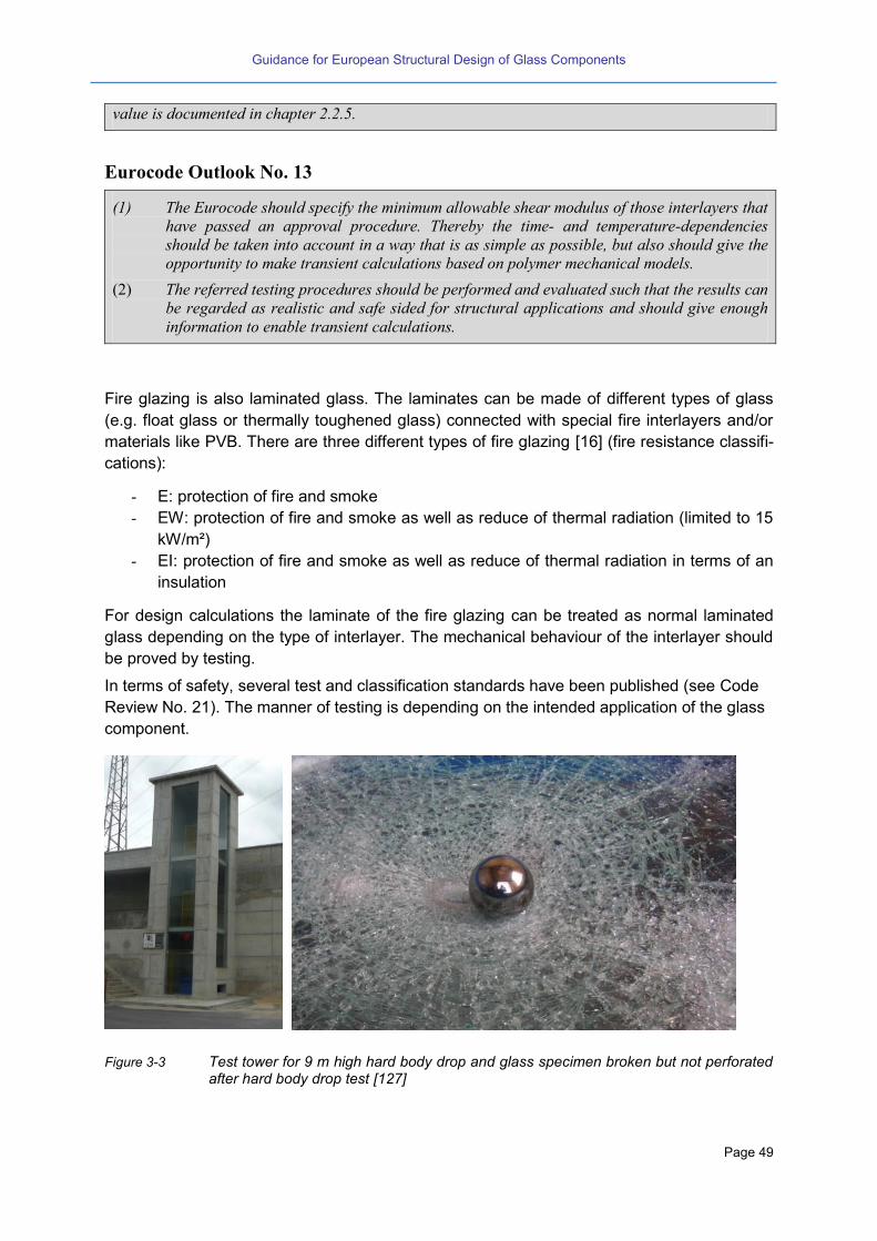
Guidance for European Structural Design of Glass Components
Page 49
value is documented in chapter 2.2.5.
Eurocode Outlook No. 13
(1) The Eurocode should specify the minimum allowable shear modulus of those interlayers that
have passed an approval procedure. Thereby the time- and temperature-dependencies
should be taken into account in a way that is as simple as possible, but also should give the
opportunity to make transient calculations based on polymer mechanical models.
(2) The referred testing procedures should be performed and evaluated such that the results can
be regarded as realistic and safe sided for structural applications and should give enough
information to enable transient calculations.
Fire glazing is also laminated glass. The laminates can be made of different types of glass
(e.g. float glass or thermally toughened glass) connected with special fire interlayers and/or
materials like PVB. There are three different types of fire glazing [16] (fire resistance classifi-
cations):
- E: protection of fire and smoke
- EW: protection of fire and smoke as well as reduce of thermal radiation (limited to 15
kW/m²)
- EI: protection of fire and smoke as well as reduce of thermal radiation in terms of an
insulation
For design calculations the laminate of the fire glazing can be treated as normal laminated
glass depending on the type of interlayer. The mechanical behaviour of the interlayer should
be proved by testing.
In terms of safety, several test and classification standards have been published (see Code
Review No. 21). The manner of testing is depending on the intended application of the glass
component.
Figure 3-3 Test tower for 9 m high hard body drop and glass specimen broken but not perforated after hard body drop test [127]

Guidance for European Structural Design of Glass Components
Page 50
Code Review No. 21
Test standards:
EN 12600 [21]: Pendulum test – Impact test method and classification for flat glass, see Code Re-
view No. 51.
EN 356 [23]: Testing and classification of resistance against manual attack
EN 1063 [24]: Testing and classification of resistance against bullet attack
EN 13541 [25]: Testing and classification of resistance against explosion pressure
3.9 Thermally curved glass
Basically, thermally curved glass panels are made of float glass. There are four different
types of production methods used to introduce the curvature:
Gravity bending and annealing: After heating the glass panel up to 600 °C, under use of
gravity the glass panel “sags” into the desired form. Afterwards the glass panel is cooled
down slowly to anneal it. An annealed curved glass panel shows similar strength qualities
like to annealed flat glass.
Gravity bending and quenching in a mould: After heating the glass up to 600°C, under
use of gravity the glass panel “falls” into the desired form into the mould. With the glass
still in the mould it is cooled down very fast. Depending on the cooling rate the glass pan-
el provides a quality in terms of pre-stressing like heat strengthened or thermally tough-
ened glass.
Gravity bending and quenching in a bending quench: After heating up the glass panel up
to 600°C, under use of gravity the glass “falls” into the desired form set by the quench, af-
ter which is cooled down very fast. Depending on the cooling rate the glass panel pro-
vides a quality in terms of pre-stressing like hear strengthened or thermally toughened
glass.
Pressure bending: After heating up to 600 °C, the glass panel is pressed in the desired
form (in general only cylindrical shape, but it can be curved in two directions) and cooled
down very fast. Depending on the cooling rate the glass panel provides a quality in terms
of pre-stressing like heat strengthened or thermally toughened glass.
The process is more difficult compared to the production of flat glass especially in view of a
reliable pre-stress. Further, processing to laminated glass or insulation glass is common.
No product standards exist for curved glass panels that may give a bending strength. Despite
of this curved glass is frequently used.
However, recent results have shown that the quality of curved glass, particularly that pro-
duced by gravity bending and quenching in a mould, is not quite comparable to flat glass.
This concerns not only the geometrical tolerances but also the strength values. The quality
control should therefore be much more severe than for flat glass.
With regard to the design rules, there are special issues that should be taken into account for
curved glass: The climatic loading of insulating glass panels is higher compared to flat glass,
which is caused by the higher geometrical stiffness. Further, the effects of deformations of
the substructure should carefully be taken into account as curved glass responds to support-
displacements with significantly higher inner forces and stresses.

Guidance for European Structural Design of Glass Components
Page 51
Code Review No. 22
Product standard:
ISO/DIS 11485: Curved Glass: This draft specifies the product “curved glass”. However, there are
no strength values given. Concerning the homogeneity of the residual stresses of curved thermally
toughened glass the specified quality and the defined “values” are relatively low.
Technical approval:
In Germany, there are technical approvals existing for curved annealed glass and curved laminated
glass. Technical approvals for thermally toughened glass are under preparation.
3.10 Chemically strengthened glass
Chemical strengthening represents a different method to improve the bending resistance of
annealed glass. Compared to thermally strengthened glass, where the breakage structure
changes totally caused by the pre-stressing, the influence of the chemical strengthening is
limited to some micrometres into the material’s depth close to the surface. The peak
strengthening is higher, but due to the low inner penetration depth it can be “easily” damaged
by scratching. In general, the use of chemically strengthened glass is for optical reasons
(higher quality). Some further application fields can be found in the aeronautical industry.
The bending strength of chemically tempered glass is given to fk,Zone 1 = 150 N/mm², but it is
well known that the scatter of the strength values is very large.
Compared to thermal pre-stressing, only relative small pane sizes are able to be chemically
pre-stressed.
Code Review No. 23
Product standard:
EN 12337 [12]: The product standard of chemically heat strengthened glass specifies a characteris-
tic strength value of 150 N/mm² for chemically strengthened glass.
Eurocode Outlook No. 14
(1) The design of chemically prestressed glass should not be considered in the Eurocode if it is
not possible to define characteristic values for different types of qualities and ensure quality
management.
3.11 Insulating glass
Insulating glass is one of the most important glass products. It can be made of all the glass
types mentioned before. To obtain an insulation effect two or more glass panels are con-
nected together by an edge seal. As the cavity between the glass panels is gas-tight (width
of 12 up to 22 mm) it can be filled with dehumidified air or inert gas to improve the effectivity
of the insulation. in the market double (two glass panels with on cavity) or triple glazing (three
glass panels with two cavities) are available.

Guidance for European Structural Design of Glass Components
Page 52
The durability of an insulation glass unit is about 20 (to 30) years. After this time a loss of the
insulation property can be observed by the occurrence of white or grey humidity traces in the
interior of the cavity.
Due to the closed cavity there is an additional inner loading that has to be taken into account.
The so-called “climatic loading” originates from climatic effects (change of temperature or
ambient air pressure) and the different altitude on site compared to that in the factory. These
effects cause stresses that have to be taken into account in the mechanical assessment of
the glass (chapter 6.1) (see Code Review No. 44).
Further, there are different types of systems and materials used for the edge bond of insulat-
ing glass units that will not be further explained here.
Eurocode Outlook No. 15
(1) Eurocode should consider the climatic loading action effects, at least in cases where they
have negative influences on the safety.
(2) Apart from the product standards, the Eurocode should specify the expected lifetime of insu-
lating glass in view of the structural verification and its supposed time period which may be
different from those of the product standards.
3.12 Channel shaped glass
In Europe channel shaped glass is known to be produced only by two factories. The basic
product is manufactured similar to patterned glass. The difference is that while the hot glass
is still plastically deformable “two wings” are bent into a U-section, so that a profile is created
with high geometrical stiffness after cooling. A processing to insulating glazing or laminated
glass is not possible, but thermally toughened glass can be produced.
There is a European standard to determine the profile bending strength. Channel shaped
glass is used for vertical applications like facades. The application rules so far available are
specified in a technical approval.
Code Review No. 24
Product standards:
EN 572-7 [7]: This standard specifies the geometrical properties and tolerances of channel shaped
glass but does not give any strength values.
prEN 15683 [15]: This standard specifies thermally toughened channel shaped glass.
Test standard:
EN 1288-4 [20]: This standard specifies a test method analogous to the application of channel
shaped glass (vertical installation with distributed loading). The bending resistance is given as
“profile bending resistance” assuming that the tests are evaluated linearly although there is a sig-
nificant geometrical non-linearity existing.
Technical approvals:
In Germany Technical approvals exist for the application of annealed channel shaped glass [74]
[75].

Guidance for European Structural Design of Glass Components
Page 53
Eurocode Outlook No. 16
(1) Also due to limited number of producers the design of channel shaped glass should not be
considered in the Eurocode.

Guidance for European Structural Design of Glass Components
Page 54
Guidance for European Structural Design of Glass Components
Page 55
4 Principles and Basic Rules for the design of glass compo-
nents and safety approach
4.1 General
What differentiates the design of structural glass elements from almost any other construc-
tion material is the fact that glass can break unexpectedly and without fault of the design or
engineer. Perhaps the glass edge was scratched or chipped during manufacture or transpor-
tation; or perhaps the glass has sustained surface damage during service due to a hard body
impact which went unnoticed; or perhaps the glass contained an impurity such as Nickel Sul-
phide which has subsequently changed phase and size in service. Whatever the reason, the
designer of a structural glass system must bear in mind that any element of the structure
might break unexpectedly at some point during the service life of the material and when this
happens, the structural integrity of the overall system must not be compromised to the extent
that progressive collapse of the entire structure is initiated.
According to the design concept of EN 1990 – Eurocode 0 [38] the verification in the Ser-
viceability Limit State (SLS) is mainly aimed at the limitation of the deflection of the struc-
tural elements. The limits depend on the application cases or the support conditions; howev-
er, concerning the design of structural glass, they are different according to the recent na-
tional codes across the European countries.
The verification in Ultimate Limit state (ULS) is intended to fulfil the structural safety, thus
it has to be carried out under very small occurrence probabilities of overloading and lower
material strength. For structural glass the safety assessment can be performed by a limita-
tion of the stresses under relevant load combinations. If there are several vector components
of stresses then, unlike for other materials, the maximum principal stresses have to be con-
sidered.
The definition of the design value Rd for glass components is different in the various Europe-
an member states. Parameters are:
Annealed or tempered glass
Plate or in-plane loading
Time duration of the loading
Material safety factor
Redundancy of laminated glass
Reduction of the design value caused by edge effects
Consideration of special applications
Reduction depending on the glass surface profile (e.g. float glass or drawn sheet glass,
as produced, sandblasted or polished)
Type of production method in case of thermally toughened glass (vertical or horizontal)
Examples can be taken from the following Code Reviews. Figure 1-7 explains the statistical
interpretation of design values for the verification in the ULS.
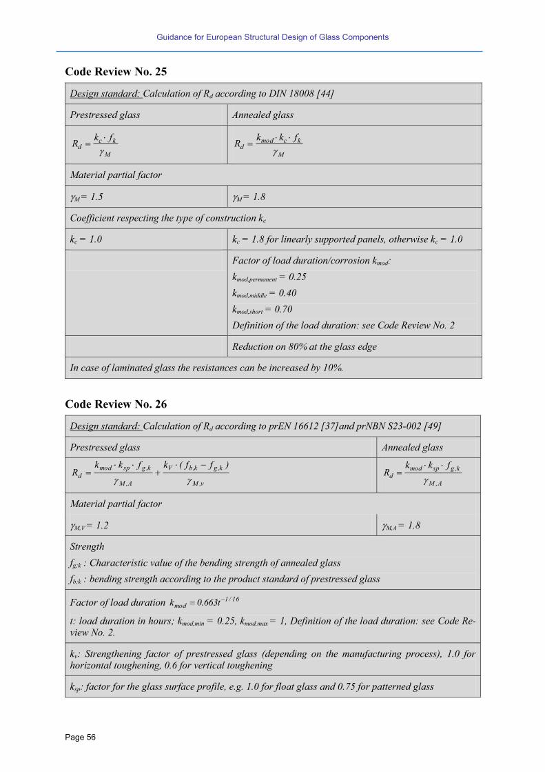
Guidance for European Structural Design of Glass Components
Page 56
Code Review No. 25
Design standard: Calculation of Rd according to DIN 18008 [44]
Prestressed glass Annealed glass
M
kcd
fkR
M
kcmodd
fkkR
Material partial factor
M = 1.5 M = 1.8
Coefficient respecting the type of construction kc
kc = 1.0 kc = 1.8 for linearly supported panels, otherwise kc = 1.0
Factor of load duration/corrosion kmod:
kmod,permanent = 0.25
kmod,middle = 0.40
kmod,short = 0.70
Definition of the load duration: see Code Review No. 2
Reduction on 80% at the glass edge
In case of laminated glass the resistances can be increased by 10%.
Code Review No. 26
Design standard: Calculation of Rd according to prEN 16612 [37]and prNBN S23-002 [49]
Prestressed glass Annealed glass
v,M
k,gk,bV
A,M
k,gspmod
d
)ff(kfkkR
A,M
k,gspmodd
fkkR
Material partial factor
M,V = 1.2 M,A = 1.8
Strength
fg;k : Characteristic value of the bending strength of annealed glass
fb;k : bending strength according to the product standard of prestressed glass
Factor of load duration 16/1mod t663.0k
t: load duration in hours; kmod,min = 0.25, kmod,max = 1, Definition of the load duration: see Code Re-
view No. 2.
kv: Strengthening factor of prestressed glass (depending on the manufacturing process), 1.0 for
horizontal toughening, 0.6 for vertical toughening
ksp: factor for the glass surface profile, e.g. 1.0 for float glass and 0.75 for patterned glass

Guidance for European Structural Design of Glass Components
Page 57
Code Review No. 27
Design standard: Calculation of Rd according to Ö B 3716 [48]
Prestressed glass Annealed glass
M
kbmodd
fkkR
Material partial factor: M = 1.5 for Float, Laminated glass made of float, heat strengthened glass,
thermally toughened glass and M = 2.0 for wired glass and patterned glass
Coefficient depending on the type of loading kb: kb = 1.0 perpendicular to the plate and kb = 0.8 in-
plane loading
Factor of load duration/corrosion kmod:
kmod = 1.0 kmod,permanent = 0.6; kmod,middle = 0.6; kmod,short = 1.0
Reduction on 80% at the glass edge
Code Review No. 28
Design standard: Calculation of Rd according to NEN 2608 [45]
Prestressed glass Annealed glass
V,M
k,gspk,bez
A,M
kspeamod
d
)fkf(kkfkkkkR
A,M
kspeamod
d
fkkkkR
Material partial factor
M,V = 1.2 M,A = 1.8 if wind is the dominant load
M,A = 2.0 for remaining loads
Coefficient depending on the type of loading ke
ke = 1.0 perpendicular to the plate
ke = 0.62 in-plane loading for heat strengthened glass
ke = 1.0 in-plane loading for thermally toughened glass
ke =0.8 perpendicular to the plate
ke = 0.62 in-plane loading
ka non-linearity: 25/1a A644.1k with A = Area of the loading in [mm²]
Factor of load duration c/1
modt
5k
,t: load duration in seconds; kmod,min = 0.25, kmod,max = 1; c:
constant of corrosion
ksp: factor for the glass surface profile, e.g. 1.0 for float glass and 0.8 for patterned glass
Zone – coefficient kz: Zone 1: kz = 1.0; Zone 2: kz = 1.0 for heat strengthened glass, kz = 0.9 for
thermally toughened glass; Zone 3 (edge): kz = 0; Zone 4: kz = 1.0 for heat strengthened glass, kz =
0.65 for thermally toughened glass

Guidance for European Structural Design of Glass Components
Page 58
Code Review No. 29
Design standard:
ASTM E1300 – 12ae1 [52]:
The maximum allowable stress (allowable) is a function of area (A), load duration in seconds (d),
and probability of breakage (Pb):
(
⁄ ⁄ )
⁄
where:
= maximum allowable surface stress,
Pb = probability of breakage,
k = a surface flaw parameter,
d = the duration of the loading,
A = the glass surface area, and
n = 16 for AN (Annealed glass).
Procedure do design secondary glass elements:
1. The specifying authority shall provide the design load (including load safety factor)
2 The non-factored load (NFL) can be derived based on design charts. NFL is a uniform lateral
load that a glazing out of annealed glass (defined by size, glass thickness and supporting condition)
can sustain, based upon a given probability of breakage (8/1000) and load duration (3 sec).
Example of a design chart:
3. The influences of a thermal pre stress and load durations different from 3 sec are considered in
glass type factors (GFT)

Guidance for European Structural Design of Glass Components
Page 59
4 For insulating glazing an additional load share factor (LS) is defined:
5 The load resistance (LR) is defined by the product: LR = NFL x GFT x LS
6 If the load resistance LR is less than the specified design load, then other glass types and thick-
nesses may be evaluated to find a suitable assembly having LR equal to or exceeding the specified
design load.
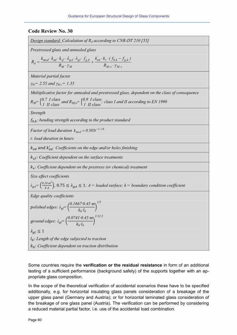
Guidance for European Structural Design of Glass Components
Page 60
Code Review No. 30
Design standard: Calculation of Rd according to CNR-DT 210 [55]
Prestressed glass and annealed glass
v,Mv;M
k,gk,bv'ed
MM
k,gglgAsfedmodd
R
)ff(kk
R
fkkkR
Material partial factor
M = 2.55 and M,v = 1.35
Multiplicative factor for annealed and prestressed glass, dependent on the class of consequence
R {0 I class1 II class
and R {0 I class1 II class
; class I and II according to EN 1990
Strength
bending strength according to the product standard
Factor of load duration 16/1mod t585.0k
t: load duration in hours
: Coefficients on the edge and/or holes finishing
Coefficient dependent on the surface treatments
Coefficient dependent on the prestress (or chemical) treatment
Size effect coefficients
g (0.2 m2
k ), ; A = loaded surface; k = boundary condition coefficient
Edge quality coefficients
olished edges: gl (0.1 0. m
kb lb)1
round edges: gl (0.0 1 0. m
kb lb)1 12.
Length of the edge subjected to traction
Coefficient dependent on traction distribution
Some countries require the verification or the residual resistance in form of an additional
testing of a sufficient performance (background safety) of the supports together with an ap-
propriate glass composition.
In the scope of the theoretical verification of accidental scenarios these have to be specified
additionally, e.g. for horizontal insulating glass panels consideration of a breakage of the
upper glass panel (Germany and Austria); or for horizontal laminated glass consideration of
the breakage of one glass panel (Austria). The verification can be performed by considering
a reduced material partial factor, i.e. use of the accidental load combination.
Guidance for European Structural Design of Glass Components
Page 61
As another example: For sloped glazing in the UK the requirements for the glass composition
depend on the installation height. Here, also the philosophy concerning the type of glazing is
different compared to other countries, because also monolithic thermally toughened glass is
allowed for horizontal applications.
In the following chapters the regulations together with the scope of application and the sup-
port conditions will be explained.
Code Review No. 31
Design Standards:
DIN 18008 [44]: Definition of the residual load-bearing capacity: ”ability of a glazing structure to
remain stable over a sufficient period for a specified damage and under defined external effects
(load, temperature etc.).” For usual applications the residual load-bearing capacity is fulfilled if
standard bearing conditions and requirements for the glass assembly are used. Only for mainte-
nance glazing and glass floors test conditions are defined in the standard.
NEN 2608 [45]: The verification of the residual resistance is mandatory. The accidental design
combination of EN 1990 [38] is used for this purpose.
Eurocode Outlook No. 17
(1) The Eurocode should harmonize the different views on the safety concepts and residual
load-bearing capacity among Europe in a consistent manner, e.g. using different classes.
4.2 Classification of structural elements of glass
According to their structural importance, the loading and the failure consequences glass el-
ements can be classified as secondary or primary element.
Characteristics of secondary elements are, that they do not take any loads from other ele-
ments or members of the superior structure and that in most cases they are loaded transver-
sally. Examples are horizontal glazing, barriers made of glass or glass floors. Usually acces-
sible and safe-guarding glass panels are also classified as secondary elements. However, in
these domains of application the risk of failure and damage is rising. Therefore for these
types of secondary elements, higher levels of safety and reliability should be required.
Secondary glass elements can be further classified according to their position, either “over-
head” or “vertically”.
As the predominant transversal loading produces bending stresses in the glass section, for
linearly supported panes the bending resistance of zone 1 and zone 2 of the glass panels is
most relevant. For point-supported glass panes additionally the bending resistance of zone 4
is also of importance. In national regulations mostly, if at all there are any design rules for
structural glass, so far only the design of “standard secondary elements” is specified.
Whereas the characteristics of primary elements are, that in general they are also loaded by
in-plane loads and that they can take loads from the superior (overall) structure or from other
elements. Despite of available research results, there are no national or international codes
in which standardized design rules can be found for the assessment of primary structural

Guidance for European Structural Design of Glass Components
Page 62
elements of glass. Therefore, at present, for primary structural glass in most cases a unique
verification will be necessary.
4.3 Secondary structural elements: robustness and residual capacity
4.3.1 General
There are the same requirements on reliability and safety for glass structures as for other
materials. However as glass always fails suddenly, i.e. no ductile post-breakage behaviour is
available, special attention has to be paid for special constructive and detailing issues to ob-
tain fail safe structures:
Creation of redundancy and residual capacity,
Protection against impact,
Avoidance of contact with hard materials (e.g. steel),
Reduction of the splinter occurrence.
The first three points aim at creating “robust” respectively “damage tolerant” structures or
elements. That means, the structure must be safe and reliable such that it does not fail with
unacceptable consequences, even in accidental cases. Therefore, robustness is a very im-
portant aim of the design, the level of which however depends on the structural role of the
element.
For example for secondary elements that are neither accessible nor safe-guarding, the re-
sidual capacities should be such, that sufficient retention can be ensured after unscheduled
breakage of a glass pane or layers of it. Thus the residual capacity depends on the
Composition and strength of the glass section,
Supports and bearing concept,
Failure scenario.
4.3.2 Composition and strength of the glass section
Structures with monolithic glass sections exhibit only poor residual capacities, thus mostly
they are only used in case of vertical applications without any additional requirements. Ade-
quate sections fulfilling higher requirements are therefore laminated or laminated safety
glasses made of float, heat strengthened or thermally toughened glass, according to the
structural purpose.
Regarding the composition of such cross-section, apart from the type of glass the residual
capacity depends also on the strength of the interlayer. As an example, a fully linearly sup-
ported laminated glass panel of two layers of float glass, connected by a strong interlayer like
a PVB-sheet, provides excellent residual capacity after breakage. In the area of a crack, the
sectional bending forces are deviated via the upper glass layer in compression and the PVB-
sheet in tension. Prerequisite to that is that the interlayer is able to carry tension forces.
Compared to that a laminated section comprising only of fully toughened glass layers does
not provide any residual load bearing capacity unless the interlayer is sufficiently stiff - as in
the case of an ionomer. The behaviour after breakage of both layers with a PVB interlayer
then, can be compared with a “wet towel” or with a “pancake”, whereas a laminated section
of heat strengthened glass-layers, or a combination of heat strengthened and toughened
Guidance for European Structural Design of Glass Components
Page 63
glass layers, provides a similar post breakage residual capacity similar to that of layers of
float (due to significantly larger shards, clamping together). Note that the post breakage re-
sidual capacity of laminated glass is the better, the “better” the support conditions are, see
next chapter.
4.3.3 Supports and bearing concept
Another determining factor for the residual load carrying capacity after breakage is the type
of support and its concept. For instance glass pieces can pull out of the fixations of the sub-
structure after breakage and drop down, with a high potential of injuring people if the sup-
ports are not adequate despite of having large glass shards. Therefore a two-sided line-type
support should not be used, unless the type of glass is laminated made of float or heat
strengthened quality. Known from experience, sufficient residual capacities can be achieved
if there are other parts of the substructure underneath the glass panel (rails, beams, trans-
versal elements etc.) that may serve as additional support in case of breakage. Also point-
supports together with laminated glass are favourable, as the point-supports can carry hori-
zontal or in-plane forces produced by the interlayer (membrane) after breakage.
4.3.4 Failure scenario
Unless other knowledge is available, the assessment of residual post breakage load carrying
capacity should be performed by testing. Thereby the failure scenario assumes the breakage
of glass layers over a residual life time under the action of a defined residual loading. It can
be assumed a failure of all glass layers or a failure of only accessible glass layers. The type
of damage and the magnitude of loading may be determined by the third party in advance.
Whereas a failure of the secondary structure of glass may occur by unforeseen impact or
similar, however the integrity and health of human people must not be affected. That con-
cerns not only persons underneath the glass panel but also persons who may fall against the
glass panel. In that case no big injuries should be allowed.
For accessible and safe guarding elements of glass the load bearing resistance, their further
specific functions and the associated splinter effects are to be assessed specifically. In gen-
eral, these investigations are carried out together with the residual capacity verifications.
Regardless of what type or concept the support is, there are exceptions for vertical glazing in
dependence on the height of mounting position or on the dimension of the glass pane.
Code Review No. 32
National Building Regulations:
In Germany [47] e.g. for glazing up to 4.0 m above ground, or for glazing of greenhouses or for
roof-windows with Areas < 1.6 m2, there are no special rules to be obeyed. Reason for this is a
drastically reduced risk of damage in these cases.

Guidance for European Structural Design of Glass Components
Page 64
Eurocode Outlook No. 18
(1) The corresponding failure scenario should be adapted individually using different classes of
failure consequences.
(2) Different European countries require different levels of post breakage safety. This should be
managed by values or rules that may be adjusted by the national application documents
(NAD).
Bomb blast is a specific scenario which can engage a glazed façade, requiring further char-
acteristics of robustness and damage tolerance to preserve integrity and health of human
people. To such respect, special attention should be paid to the possible generation of glass
splinters, to their energy and related flight trajectory (see chapter 4.5.2).
As a consequence, a clear definition (by analysis and by testing) of the post-breakage be-
haviour of a glass element becomes of paramount importance in this case and the applica-
tion of laminated glass, as well as of appropriate supports, are key features of an effective
design.
Code Review No. 33
Test Standards:
EN 13541 [25]: This European Standard specifies a test method, performance requirements and
classification for explosion pressure resistant glazing for use in buildings. It concerns a method of
test against blast waves generated using a shock tube or similar facility to simulate a high explosive
detonation. The classification is only valid for tested glass sizes of about 1 m2. Based on theoretical
considerations and/or experimental work, the results can be used for estimating the explosion-
pressure-resistance of other glass sizes.
EN 13123-1 [26]: This European Standard specifies the criteria which windows, doors and shutters
shall satisfy to achieve a classification when submitted to the test method described in EN 13124-1.
It concerns a method of test against blast waves generated by using a shock tube facility to simulate
a high explosive detonation in the order of 100 kg to 2 500 kg TNT at distances from about 35 m to
50 m.
EN 13123-2 [26]: This European Standard specifies the criteria which windows, doors and shutters
shall satisfy to achieve a classification when submitted to the test method described in EN 13124-2.
It concerns a test method against blast waves in open air resulting from high explosives that can be
carried by hand and placed a few metres from a target. Controlled measurement of the actual blast
on the face of the test specimen being difficult, costly and subject to inaccuracy, consistency of the
blast forces is therefore controlled in this standard by the characteristics of the explosive charge
and its location.
EN 13124-1 [27]: This European Standard specifies a conventional test procedure to permit classi-
fication of the explosion resistance of windows, doors and shutter together with their infill. It con-
cerns a method of test against blast waves generated by using a shock tube facility to simulate a
high explosive detonation in the order of 100 kg to 2 500 kg TNT at distances from about 35 m to 50
m.
EN 13124-2 [27]: This European Standard specifies a test procedure to permit classification of the
explosion resistance of windows, doors and shutters together with their infill. It concerns a test
method against blast waves in open air resulting from high explosives that can be carried by hand
and placed a few metres from a target.

Guidance for European Structural Design of Glass Components
Page 65
ISO 16933 [28]: This ISO Standard provides a structured procedure to determine the air-blast re-
sistance of glazing and sets forth the required apparatus, procedures, specimens, other require-
ments and guidelines for conducting arena air-blast tests of security glazing. Seven standard blasts
simulating vehicle bombs and seven standard blasts simulating smaller satchel bombs that can be
used to classify glazing performance are incorporated in this International Standard. Classification
and ratings are assigned based on the performance of glazing loaded by air-blast pressures and
impulses.
Eurocode Outlook No. 19
(1) Eurocode should specify the glass strength (for annealed, heat strengthened and thermally
tempered glass) for very fast loading conditions, like blast events based on experimental and
theoretical data to be evaluated in research.
(2) Eurocode should alert the reader about the importance of a “fully dynamic approach” (i.e.
both material properties and structure response) in the analysis for designing against blast
loads. This also means that the sub-structure has to be taken into consideration next to ap-
plying test results from small size elements to full scale facades.
4.3.5 Further general construction rules
The design of glass components should be performed with regard to the following:
A glass-steel-contact or a glass-glass-contact must be avoided.
The glass panels should be fixed in their positions with brackets or frames without exces-
sive constraint.
The materials of the supports must be durable for the expected life time.
The drying of humidity near to the edges of laminated glass has to be enabled.
Recommendations like these are described in the design standards or in execution rules.
Thermal stresses should be considered in cases where relevant potential heat absorption is
present. This may be caused by e.g. partial shading or coatings. E.g. in Germany, there is no
thermal stress calculation method present but an appropriate type of glazing (e.g. tempered
glass) is chosen in case of a potential risk of breakage due to thermal stresses. In other Eu-
ropean countries calculation methods are present to take into account the load case “thermal
stress”.
Code Review No. 34
Design Standards:
NF P78-201; NF-DTU 39 [59]: The standard allows a rational choice of glass as a consequence of
possible thermally induced stresses, which in turn are consequence of thermal gradients in the glass
pane. Essentially, this document allows the calculation of thermal gradients in the glass pane and a
comparison with allowable values.
It accounts for:
Boundary conditions, e g. frame inertia, stores, ventilation, proximity to heating devices,
shadows, etc.
Climatic conditions, e.g. seasonal environmental temperatures, solar irradiation, etc.

Guidance for European Structural Design of Glass Components
Page 66
Special installation conditions, e.g. stepped glass, overhanging glass panes, sliding doors,
etc.
It proposes three calculation methods, of different level, to ascertain the temperature gradients in
the glass pane:
1) Calculation in transitory state: this is the most general and precise one, applicable to any
condition; it is quite complicated and it requires to deal with it by means of a numerical
computing method.
2) Calculation in steady state: it is a simplified approach, it can be applied only in case of low
inertia frames (as defined in the standard). It allows a less precise and more conservative
result.
3) Hand calculation in steady state: it is a simplified approach, it can be applied only in case
of low inertia frames (as defined in the standard). It allows a less precise and more con-
servative result.
Finally, the calculated temperature gradients can be compared with allowable ones, depending
upon thermal treatment of glass, edge finishing and shape, frame thermal inertia, etc.
A European draft for a thermal stress calculation method exists [51]. This draft is based on design
methods used in the UK [86], Belgium [87] and France [59]. The results of the calculation are a
necessary type of glass (annealed or tempered) and a necessary edge finishing depending on the
thermal restraints. Thereby the design value is the allowable temperature difference T in the glass
plane. Values are given in the product standards.
Furthermore the ASTM-Code E2431-06 185 [53] gives a method to calculate the resistance of an-
nealed glass to thermal loading. The failure modus due to thermal stresses is given by the edge re-
sistance of zone 2. According to EN 1990 in [51] there is no relation between a failure probability
and the material resistance. The values are rather based on experience. Nevertheless the ASTM-
Code [53] gives a relation between the glass size, the thermal load and the edge resistance.
Eurocode Outlook No. 20
(1) calculation method for the load case “thermal stresses” should be established in the Eu-
rocode. The existing methods should be analysed and adjusted to fit with the Eurocode safe-
ty framework (mean value, standard deviation and design value). This means that also the
loads from other Eurocodes have to be adopted to the specific need in glass design.
4.4 Primary structural elements: glass-robustness and damage toler-
ance
If structural glass is used for primary elements, the field where available standards and
codes regulate the design and define the level of safety is left. This is for instance the case
for columns, shear panels used for bracing systems, lattice girders with glass elements,
beams subject to bending etc.
Here, apart from the theoretical assessment of the ultimate load bearing capacity a consider-
able robustness has always to be verified additionally, the requirements of which are of
course significantly higher as those for secondary elements. However despite of a good de-
gree of scientific and technical knowledge, rules on this have not been introduced in codifica-
tion so far.
Thus for primary elements of glass normally a unique verification procedure will apply.
Thereby an individual safety concept with regard to the loading and unforeseen breakage

Guidance for European Structural Design of Glass Components
Page 67
has to be elaborated. This comprises also the assigns use of the structure, damage likeli-
ness, damage consequences and the adjunct risk of damage respectively failure. Finally an
increased quality assessment of material, fabrication and erection should be installed.
Characteristics of robustness and damage tolerance of primary structural elements may be:
Redundancies of the overall structure. Herewith the creation of background load carrying
mechanisms is meant, that can be activated and which prevent a total failure of the build-
ing or whole structure.
Redundancies of the cross-section. This can be achieved by the choice of laminated
glass with an adequate composition and balance of strength, size of shards, strength of
interlayer and ductility of interlayer, in order to provide a safe residual capacity in case of
breakage of one of the glass layers. Although this requirement is already necessary with-
in the scope of secondary elements, here they are higher as no failure of the element can
be allowed due to the fact that primary elements take over loads of the global structure.
Protection against hard impact. Like for secondary elements the load carrying inner glass
layers are to be protected against any hit or any impact. Thus they are to be protected by
outer layers of glass in a laminated package. The edges of the load carrying “core layers”
should or may (according to the use of the element) also be protected against hard im-
pact. Contrary to secondary elements again the requirements here are considerably
higher.
Prevention of Steel-Glass-Contact or contact with hard materials. Not only an unsched-
uled contact with hard materials, such as steel or concrete has to be generally avoided,
but also in the design of the load introduction special attention must be paid in view of a
smooth distribution of the load and avoidance of stress peaks. This may be enabled by
the use of reliable mortar fillings/layers or polymeric components.
Protection of people against splinters and shards that may fall down or threaten people
else how: this is analogous to secondary elements.
About fire actions there should be clarifications whether fire is a design issue for the compo-
nent or not. If so, then protective means (fire glass) or additional robustness and/or redun-
dancy measures (background safety in case of failure of glass due to fire) need to be ap-
plied.
The wall-like or pane-like glass columns of the Rheinbach-pavillon, Figure 4-1, may serve as
an example for the above mentioned considerations. The roof of which is solely carried by
vertical laminated glass panes. These glass-columns are oriented towards two perpendicular
directions in the ground layout, so that they also take over the lateral bracing of the building.
That means that forces from tension, compression and wind moments (and also from impact
and imperfections) are introduced in plane of the glass panels. Additionally, transverse loads
(wind loads) have to be carried perpendicular to the plane of the glass.
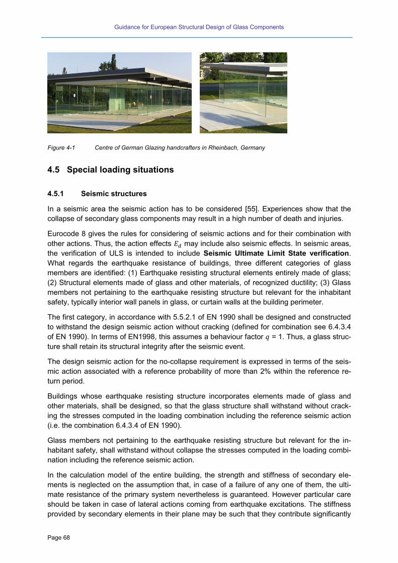
Guidance for European Structural Design of Glass Components
Page 68
Figure 4-1 Centre of German Glazing handcrafters in Rheinbach, Germany
4.5 Special loading situations
4.5.1 Seismic structures
In a seismic area the seismic action has to be considered [55]. Experiences show that the
collapse of secondary glass components may result in a high number of death and injuries.
Eurocode 8 gives the rules for considering of seismic actions and for their combination with
other actions. Thus, the action effects may include also seismic effects. In seismic areas,
the verification of ULS is intended to include Seismic Ultimate Limit State verification.
What regards the earthquake resistance of buildings, three different categories of glass
members are identified: (1) Earthquake resisting structural elements entirely made of glass;
(2) Structural elements made of glass and other materials, of recognized ductility; (3) Glass
members not pertaining to the earthquake resisting structure but relevant for the inhabitant
safety, typically interior wall panels in glass, or curtain walls at the building perimeter.
The first category, in accordance with 5.5.2.1 of EN 1990 shall be designed and constructed
to withstand the design seismic action without cracking (defined for combination see 6.4.3.4
of EN 1990). In terms of EN1998, this assumes a behaviour factor = 1. Thus, a glass struc-
ture shall retain its structural integrity after the seismic event.
The design seismic action for the no-collapse requirement is expressed in terms of the seis-
mic action associated with a reference probability of more than 2% within the reference re-
turn period.
Buildings whose earthquake resisting structure incorporates elements made of glass and
other materials, shall be designed, so that the glass structure shall withstand without crack-
ing the stresses computed in the loading combination including the reference seismic action
(i.e. the combination 6.4.3.4 of EN 1990).
Glass members not pertaining to the earthquake resisting structure but relevant for the in-
habitant safety, shall withstand without collapse the stresses computed in the loading combi-
nation including the reference seismic action.
In the calculation model of the entire building, the strength and stiffness of secondary ele-
ments is neglected on the assumption that, in case of a failure of any one of them, the ulti-
mate resistance of the primary system nevertheless is guaranteed. However particular care
should be taken in case of lateral actions coming from earthquake excitations. The stiffness
provided by secondary elements in their plane may be such that they contribute significantly
Guidance for European Structural Design of Glass Components
Page 69
to the interstory lateral stiffness, even if, due to the minimal ductility, no allowance is actually
given to such stiffness in the calculation model.
Under these premises two requirements are specified:
Under ultimate limit states, the strength and resistance of the structural system, based
on primary elements only, shall be checked, and the secondary elements shall be veri-
fied for the lateral loads directly applied onto them, and for the displacements imposed
by the compliance to the deformations of the primary system.
Under damage limitation states, in case the contribution of secondary members to the
overall system stiffness is relevant, this contribution shall be taken into account, and
the resulting stresses on the glass secondary elements shall be added to the lateral
loads directly applied onto them.
In general damage limit states are analysed for loading conditions that are less severe than
under ultimate limit states, and the first loading combination in ultimate limit states is govern-
ing the design.
While, as already mentioned, damage limit states are analysed for loading conditions that are
less severe than under ultimate limit states. The additional stiffness provided by secondary
elements may result under seismic conditions in damage limit states requirements that are
governing the design.
A secondary structural element is by definition also a secondary seismic member (element).
The interstory drifts of the building are deemed to be limited in accordance with the require-
ment of displacement compatibility with respect to the glass elements. This secondary seis-
mic member and its connections shall be designed and detailed to avoid cracking during the
seismic event associated with the no-collapse requirement. Moreover, a secondary member
and its connection shall withstand the self-weight and the out-of-plane load, when subjected
to the displacements caused by the most unfavourable seismic design condition. Due allow-
ance of second order effects ( effects) should be made in the design of secondary
seismic members.
Glass secondary structural elements in seismic areas should be constructed after the hard-
ening of the concrete structures or the assembly of the steel frame. These elements can be
in contact with the structures (i.e. without special separation joints), but shall be without
structural connection to it.
Independently from the safety margin of the compatibility verification, for the secondary struc-
tural elements appropriate measures should be taken to avoid cracking, brittle failure and
disintegration of the glass during an earthquake due to the drift of the structure. Conversely,
the partial or total out-of-plane collapse of the elements is unlikely, since the strength-to-
mass ratio of a glass element is very high.
The Seismic Ultimate Limit State verification of the primary seismic members has to consider
that the contribution given by the glass structure to the seismic action resisting system in-
clude no ductility. Accordingly, the glass structure may belong to the lateral and vertical force
resisting system only, while it cannot belong to the energy-dissipation systems.
Consequently, the Seismic Ultimate Limit State verifications have to be based on linear anal-
yses with energy behaviour factor equal to one (i.e. no energy dissipation and no ductility).

Guidance for European Structural Design of Glass Components
Page 70
A primary seismic member and its connections shall be designed and detailed to carry loads
from the overall structure or from other elements (superior order), in addition to its self-weight
and the out-of-plane load, when subjected to the displacements caused by the most unfa-
vourable seismic design condition.
If the seismic action resisting system includes dissipative system (e.g. hybrid seismic struc-
ture composed of the glass system and another system, such as reinforced concrete or a
steel frame), the design is required to comply with the hierarchy of resistance. To this end,
the failure of the glass system is only allowed to occur for displacements greater than those
produced by the seismic action associated with the no-collapse requirement. Such hierarchy
of resistance aims at ensuring an overall dissipative and ductile behaviour, as it is displayed
by the structures made of different material from glass. Moreover, the hierarchy of resistance
aims at avoiding brittle failure or a premature formation of unstable mechanisms. To this end,
resort shall be made to the capacity design procedure, which is used to obtain the hierarchy
of resistance of the various structural components and failure modes necessary for ensuring
a suitable plastic mechanism and for avoiding brittle failure modes.
The connection of primary seismic members shall be verified with the seismic action associ-
ated with the no-collapse requirement. The verification has to consider both relative dis-
placements and internal actions.
Code Review No. 35
Technical recommendation:
Proposition de fiche (CSTB et SNFA) [72]:
Seismic action is divided in two types of solicitations: a dynamic solicitation due to ground move-
ment and a static deformation induced by building floor drift. The amplitude of calculated action
depends on building importance, type of ground and seismicity region. In France, the application of
seismic reglementation based on Eurocode 8 led to recommendations on façade conception and
dimensioning. The validation criterion has been chosen as no elements fall, with performance con-
servation for important buildings (hospitals firehouses…).
The experimental tests carried out on glass façades (curtain walls and structural glazing kit)
showed a large elastic deformability of the metallic frame under dynamic solicitation (succession of
increasing accelerations until 16 m/s² at different frequencies between 1 and 15 Hz applied on a 3
m x 3 m mock-up) inducing few systems degradations. Degradations have been observed during
floor drifting (static cyclic increasing displacement until 60 mm at the head of a 3 m x 3 m mock-up)
with glass breakage.
Recommendations concern calculation of anchoring to the structure, dimensioning of metallic
frame, type of glass to use.
Eurocode Outlook No. 21
(1) The Eurocode should give rules for glass components (secondary and primary) built in
seismic areas unless they will be considered in Eurocode 8 (EN 1998) [43]. In any case the
rules should comply to EC 8 general provisions.
4.5.2 Blast loads
In the last years the protection against terroristic attacks became an additional issue. When
analysing bomb attacks the leading risk is actually to be heavily injured by highly accelerated
Guidance for European Structural Design of Glass Components
Page 71
glass splinters. Therefore the performance requirements of potentially attacked buildings
often contain a certain level of blast load enhancement of the façade and in particular the
glazing. This enhancement is specified by a load assumption – described by a positive im-
pulse and a peak reflected pressure – and a performance requirement – described by the
allowed flight distance of glass splinters in a norm size test box. This means that laminated
safety glass is allowed to break, but the glass splinters should be kept attached to the foil, or
if the splinters were detached, they must not be accelerated too much.
The acceleration of the glass splinters could be limited if significant shares of the blast load
energy is absorbed before the laminated glass breaks. This absorption could be achieved by
plastic deformation of classical façade components or by adding additional crash elements
[121].
As a result of the detonation of an explosive charge a pressure shock wave spreads initially
spherical in all directions, until it is reflected by surfaces (buildings, ground). Through the
explosion, a very large amount of energy is released within a few nanoseconds. The pres-
sure increase is in a time range of nanoseconds and the duration of the overpressure phase
in the range of milliseconds. The short period of overpressure is characterized by the peak
overpressure and by the time . The integration of pressure over time results in the spe-
cific impulse . The overpressure phase is followed by a negative pressure phase which is
longer than the overpressure phase; the magnitude of the negative pressure is usually much
lower than the magnitude of the overpressure.
Above all other influences the effective mass of explosive material, but also its height
above the ground and the distance to the building (usually called standoff distance) affect
the pressure time history of an explosion. The mass of the explosive material W is usually
defined as the TNT equivalent mass (TNT= trinitrotoluene, commonly used military explo-
sive). Other parameters are possible obstacles, such as protective walls or upstream build-
ings, as well as the type and geometry of the building itself. A parameter usually defined in
the common practice is the scaled distance :
√ (4-1)
The peak reflected overpressure is formed by the reflection of the incident plane shock
wave which encounters a surface under some angle. The ratio of the peak reflected over-
pressure and incident peak overpressure is called the reflection factor. The reflection factor
therefore depends on the incident peak overpressure and on the angle between the shock
front and the surface.
Once the reflection factor is known, the reflected pressure time history can be derived, which
has a similar time history as the incident pressure if interaction effects are neglected. Figure
4-2 shows a typical reflected pressure-time history of an explosion in air.

Guidance for European Structural Design of Glass Components
Page 72
Figure 4-2 Schematic diagram of pressure time history of an explosion in air.
The determination of the complete reflected pressure time history is essential for the struc-
tural analysis, because using only the reflected peak pressure the design will typically result
to become oversized.
Since it is very complex to determine the complete pressure time history due to a detonation
and all reflection effects, standardized explosion load assumptions were set out first in the
United States and then internationally ([73] [33] [97]). These explosion load assumptions
provide a linear triangular history for the reflected pressure. The reflected pressure is charac-
terized by the reflected peak overpressure and by the positive pulse . The duration of
the overpressure phase in this linear approach is defined by:
0
,ˆ
2
r
rlind
p
it
(4-2)
The influence of the negative phase is neglected in these standardized approaches. This is
justified for the dynamic calculation of rigid or heavy structures (e.g. reinforced concrete
structures), because the negative phase hardly affects the structural response in these cas-
es. On the other hand the negative phase can affect significantly the structural response of
lighter and more flexible systems with lower natural frequencies [98][99]. Despite this influ-
ence, which is present in cable net facades for instance, only standardized explosion load
scenarios in accordance with US or ISO standard are specified in most cases. It is assumed
that the failure of the façade to the internal side is the critical design intent. Therefore the
impact on people in the interior of the building should be minimized. A failure of the system to
the outside due to the negative phase is accepted.
In Code Review No. 36 and Code Review No. 37 the essential design loads are grouped
according to the US GSA/ISC standard and according to the international ISO standard. The
given quantities of explosives (TNT equivalent mass) and the so-called stand-off specify
which explosives would create these loads in a ground detonation in front of a large façade.
To protect persons behind the facade from major injuries, an explosion-resistant function of
the facade is frequently specified. Most specifications refer to a classification of the perfor-
mance condition according to the US GSA standard (see Code Review No. 38). The GSA
method classifies facades into six protection and risk classes.

Guidance for European Structural Design of Glass Components
Page 73
Code Review No. 36
Design Standard: DSA [73]: Explosion scenarios of the US General Services Administration
(GSA/ISC)
scenario 0
ˆrp
[kPa]
ri
[kPa ms]
lindt ,
[ms]
mass TNT
[kg]
stand-off
[m]
GSA C 27,58 193,06 14,0 47,5 30
GSA D 68,95 675,71 19,6 340 34
Code Review No. 37
Test Standard: ISO 16933 [33]: Explosion scenarios (vehicles bombs) of the ISO 16933, Annex C1
Class Peak reflect-
ed overpres-
sure
Reflected
Impulse
Length of over-
pressure phase
(linear)
Stand-off 100 kg
TNT in front of
small mock-up
(3,15m x 3,15m)
Equivalent ex-
plosion scenario
in front of large
facade
0ˆ
rp
[kPa]
ri
[Pa s]
lindt ,
[ms]
Stand-off
[m]
TNT
[kg]
EXV 45 30 180 12 45 30
EXV 33 50 250 10 33 30
EXV 25 80 380 9,5 25 40
EXV 19 140 600 8,6 19 64
EXV 15 250 850 6,8 15 80
EXV 12 450 1200 5,3 12 100
EXV 10 800 1600 5,0 10 125
Code Review No. 38
Test Standard:GSA-TS01-2003 [34]:

Guidance for European Structural Design of Glass Components
Page 74
GSA/ICE performance conditions for window system response
Performance
Condition
Protection
Level
Hazard
Level
Description of Window Glazing Response
1 Safe None Glazing does not break. No visible damage to glazing or
frame.
2 Very High None Glazing cracks but is retained by the frame. Dusting or
very small fragments near sill or on floor acceptable.
3a High Very Low Glazing cracks. Fragments enter space and land on floor
no further than 3.3 ft. from the window.
3b High Low Glazing cracks. Fragments enter space and land on floor
no further than 10 ft. from the window.
4 Medium Medium Glazing cracks. Fragments enter space and land on floor
and impact a vertical witness panel at a distance of no
more than 10 ft. from the window at a height no greater
than 2 ft. above the floor.
5 Low High Glazing cracks and window system fails catastrophically.
Fragments enter space impacting a vertical witness panel
at a distance of no more than 10 ft. from the window at a
height greater than 2 ft. above the floor.
4.6 Potential classification of glass components
As mentioned before, the philosophy concerning the required type of glazing and the consid-
eration of failure scenarios is different throughout the European countries. The following re-
view shows an extract of national regulations concerning the classification of glazing and
allowed types of glass for roof glazing without any additional requirements like maintenance
scenarios.
And further, the following Eurocode Outlook gives an overview of the most used types of
glass components and their type of loading. The proposed classification is related to the risk
of consequences in case of a system failure.
Code Review No. 39
Design Standards:
DIN 18008 [44]: The German design code distinguishes between “horizontal” and “vertical” glaz-
ing. The limit is reached when the panel is tilted with 10° out of the vertical.
ÖNORM B 3716 [48]: In Austria the limit is defined to 15° out of the vertical.
BS 5516 [54]: In the UK the limit is defined to 15° out of the vertical.
Code Review No. 40
Design Standards: Roof or canopy glazing
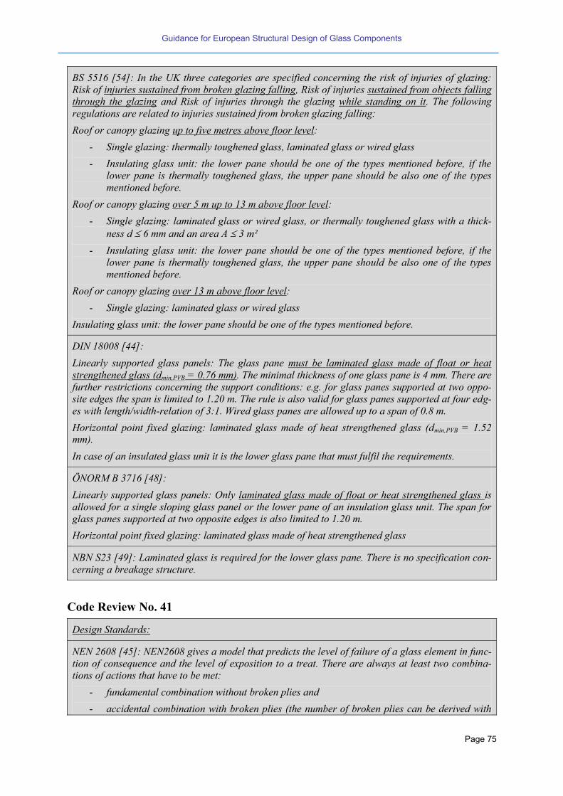
Guidance for European Structural Design of Glass Components
Page 75
BS 5516 [54]: In the UK three categories are specified concerning the risk of injuries of glazing:
Risk of injuries sustained from broken glazing falling, Risk of injuries sustained from objects falling
through the glazing and Risk of injuries through the glazing while standing on it. The following
regulations are related to injuries sustained from broken glazing falling:
Roof or canopy glazing up to five metres above floor level:
- Single glazing: thermally toughened glass, laminated glass or wired glass
- Insulating glass unit: the lower pane should be one of the types mentioned before, if the
lower pane is thermally toughened glass, the upper pane should be also one of the types
mentioned before.
Roof or canopy glazing over 5 m up to 13 m above floor level:
- Single glazing: laminated glass or wired glass, or thermally toughened glass with a thick-
ness d 6 mm and an area A 3 m²
- Insulating glass unit: the lower pane should be one of the types mentioned before, if the
lower pane is thermally toughened glass, the upper pane should be also one of the types
mentioned before.
Roof or canopy glazing over 13 m above floor level:
- Single glazing: laminated glass or wired glass
Insulating glass unit: the lower pane should be one of the types mentioned before.
DIN 18008 [44]:
Linearly supported glass panels: The glass pane must be laminated glass made of float or heat
strengthened glass (dmin,PVB = 0.76 mm). The minimal thickness of one glass pane is 4 mm. There are
further restrictions concerning the support conditions: e.g. for glass panes supported at two oppo-
site edges the span is limited to 1.20 m. The rule is also valid for glass panes supported at four edg-
es with length/width-relation of 3:1. Wired glass panes are allowed up to a span of 0.8 m.
Horizontal point fixed glazing: laminated glass made of heat strengthened glass (dmin,PVB = 1.52
mm).
In case of an insulated glass unit it is the lower glass pane that must fulfil the requirements.
ÖNORM B 3716 [48]:
Linearly supported glass panels: Only laminated glass made of float or heat strengthened glass is
allowed for a single sloping glass panel or the lower pane of an insulation glass unit. The span for
glass panes supported at two opposite edges is also limited to 1.20 m.
Horizontal point fixed glazing: laminated glass made of heat strengthened glass
NBN S23 [49]: Laminated glass is required for the lower glass pane. There is no specification con-
cerning a breakage structure.
Code Review No. 41
Design Standards:
NEN 2608 [45]: NEN2608 gives a model that predicts the level of failure of a glass element in func-
tion of consequence and the level of exposition to a treat. There are always at least two combina-
tions of actions that have to be met:
- fundamental combination without broken plies and
- accidental combination with broken plies (the number of broken plies can be derived with
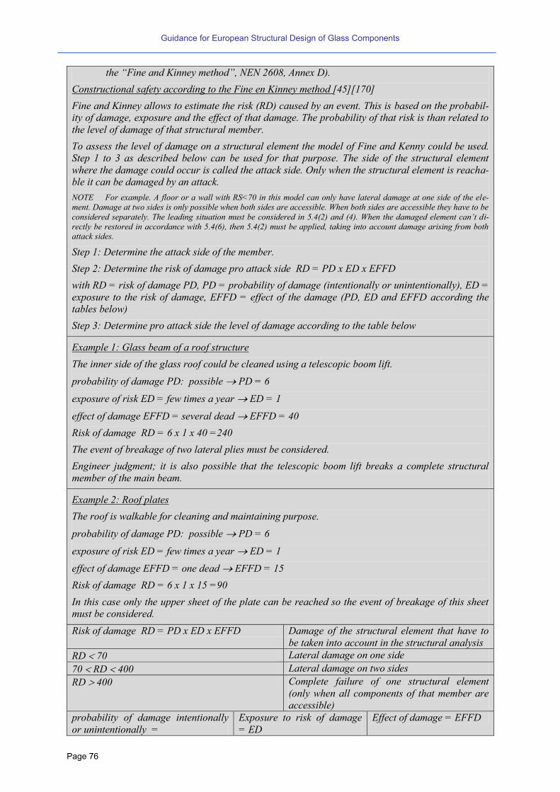
Guidance for European Structural Design of Glass Components
Page 76
the “Fine and Kinney method” NEN 2608, Annex D).
Constructional safety according to the Fine en Kinney method [45][170]
Fine and Kinney allows to estimate the risk (RD) caused by an event. This is based on the probabil-
ity of damage, exposure and the effect of that damage. The probability of that risk is than related to
the level of damage of that structural member.
To assess the level of damage on a structural element the model of Fine and Kenny could be used.
Step 1 to 3 as described below can be used for that purpose. The side of the structural element
where the damage could occur is called the attack side. Only when the structural element is reacha-
ble it can be damaged by an attack.
NOTE For example. A floor or a wall with RS<70 in this model can only have lateral damage at one side of the ele-
ment. Damage at two sides is only possible when both sides are accessible. When both sides are accessible they have to be
considered separately. The leading situation must be considered in . (2) and ( ). When the damaged element can’t di-
rectly be restored in accordance with 5.4(6), then 5.4(2) must be applied, taking into account damage arising from both attack sides.
Step 1: Determine the attack side of the member.
Step 2: Determine the risk of damage pro attack side RD = PD x ED x EFFD
with RD = risk of damage PD, PD = probability of damage (intentionally or unintentionally), ED =
exposure to the risk of damage, EFFD = effect of the damage (PD, ED and EFFD according the
tables below)
Step 3: Determine pro attack side the level of damage according to the table below
Example 1: Glass beam of a roof structure
The inner side of the glass roof could be cleaned using a telescopic boom lift.
probability of damage PD: possible PD = 6
exposure of risk ED = few times a year ED = 1
effect of damage EFFD = several dead EFFD = 40
Risk of damage RD = 6 x 1 x 40 =240
The event of breakage of two lateral plies must be considered.
Engineer judgment; it is also possible that the telescopic boom lift breaks a complete structural
member of the main beam.
Example 2: Roof plates
The roof is walkable for cleaning and maintaining purpose.
probability of damage PD: possible PD = 6
exposure of risk ED = few times a year ED = 1
effect of damage EFFD = one dead EFFD = 15
Risk of damage RD = 6 x 1 x 15 =90
In this case only the upper sheet of the plate can be reached so the event of breakage of this sheet
must be considered.
Risk of damage RD = PD x ED x EFFD Damage of the structural element that have to
be taken into account in the structural analysis
RD 70 Lateral damage on one side
70 RD 400 Lateral damage on two sides
RD 400 Complete failure of one structural element
(only when all components of that member are
accessible)
probability of damage intentionally
or unintentionally =
Exposure to risk of damage
= ED
Effect of damage = EFFD
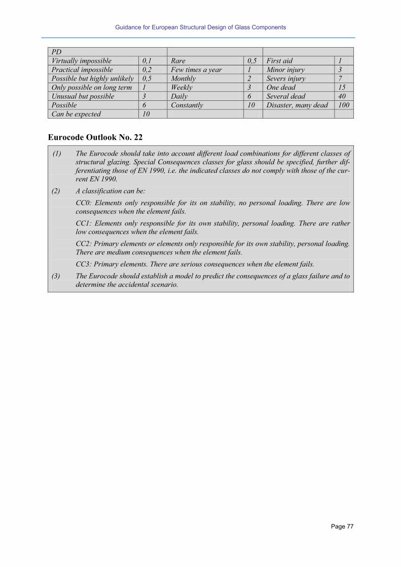
Guidance for European Structural Design of Glass Components
Page 77
PD
Virtually impossible 0,1 Rare 0,5 First aid 1
Practical impossible 0,2 Few times a year 1 Minor injury 3
Possible but highly unlikely 0,5 Monthly 2 Severs injury 7
Only possible on long term 1 Weekly 3 One dead 15
Unusual but possible 3 Daily 6 Several dead 40
Possible 6 Constantly 10 Disaster, many dead 100
Can be expected 10
Eurocode Outlook No. 22
(1) The Eurocode should take into account different load combinations for different classes of
structural glazing. Special Consequences classes for glass should be specified, further dif-
ferentiating those of EN 1990, i.e. the indicated classes do not comply with those of the cur-
rent EN 1990.
(2) A classification can be:
CC0: Elements only responsible for its on stability, no personal loading. There are low
consequences when the element fails.
CC1: Elements only responsible for its own stability, personal loading. There are rather
low consequences when the element fails.
CC2: Primary elements or elements only responsible for its own stability, personal loading.
There are medium consequences when the element fails.
CC3: Primary elements. There are serious consequences when the element fails.
(3) The Eurocode should establish a model to predict the consequences of a glass failure and to
determine the accidental scenario.

Guidance for European Structural Design of Glass Components
Page 78

Guidance for European Structural Design of Glass Components
Page 79
5 Mechanical basics and verification approach for monolithic
and laminated plates and beams
5.1 General
The most frequent types of transverse loading on glass panes are continuously or equally
distributed loads such as wind, snow, self-weight or traffic loads.
Whereas for small deflections (w < t) the plate behaves linearly, for greater deformations a
considerably non-linear effect becomes important (for length-to-width-ratios of 1:1 to 3:1).
Because then a part of the transverse load is being carried by membrane forces due to the
sagging of the plate. The occurring membrane forces are anchoring in an inner circumferen-
tial ring so that no exterior anchoring is needed. This effect is associated with in-plane de-
formations. Because of that, generally, in-plane and out-of-plane effects are to be considered
together. The theory assumes the evenness of the cross-section according to Bernoulli and
further the law of Hooke. Both assumptions are fulfilled perfectly by monolithic glass.
Today mostly glass panes are calculated numerically using FEM, in particular in cases when
they are point supported. However a short description of the analytical interdependencies
explains these effects.
5.2 Linear and non-linear plate theory
Linear plate theory. The well-known differential equation of a transversally loaded plate
y,xq
y
w
yx
w2
x
w
112
dE4
4
22
4
4
4
2
3
respectively (5-1)
y,xqwB (5-2)
gives sufficiently exact solutions for stress and deformation in general when the deflections
are small with .
Second order effect. The plate equation can be extended by moments from in-plane normal
forces/stresses multiplied by the occurring deformations (or eccentricities)
2
22
2
2
4
4
22
4
4
4
2
3
22112 y
w
yx
w
x
wd
x
w
yx
w
x
wdEyxyx
y,xq (5-3)
or in another form
yxqwwwdwwwB yxyx ,22 '"""" (5-4)
For particular cases the equations can be reduced either to the bending differential equation
of a beam or to the buckling differential equation of a column.
Plate with bending together with in-plane membrane deformations (solid-distortion).
When formulating the equilibrium at an arbitrary infinite element as well as the compatibility
Guidance for European Structural Design of Glass Components
Page 80
of the strains and couple both information via the law of Hooke, this leads to the elastic non-
linear plate-membrane differential equation according to Airy (without temperature restraint):
02
4
4
22
4
4
4
yxxx
respectively 02
""" or
0
(5-5)
with Airy´s stress-functions
d
N
x
xx
2
2
,d
N
y
y
y
2
2
,yx
xy
xyd
N
yx
2
(5-6)
respectively in the format
0
yx12
yxxyxy
2
y2
2
2
2
x2
2
2
2
(5-7)
By this the membrane differential equation is coupled to the plate differential equation via the
out-of-plane deformations. This system then is non-linear describing the membrane effects
e.g. caused by larger out-of-plane deformations. The so extended geometrical relationships
2
2
1
x
w
x
uxx ,
2
2
1
y
w
y
vyy ,
y
w
x
w
x
v
y
uxy
(5-8)
lead to the coupled non-linear differential equation system
wB y,xqw"'w'"wd 2 (5-9)
w"w'wE 2
(5-10)
From these equations it can be seen that also under pure transverse loading the plate will
response with membrane effects, too, and moreover these equations also show the already
mentioned circumferential compression ring. However, this becomes only relevant at defor-
mations , which is frequently the case in glass design.
5.3 Plates with monolithic sections of glass under transverse loading
The solutions for the plate equation are basically of the form (e.g. [172])
qtE
akw w
3
4
and qt
ak
2
(5-11)
where the factors considering the geometry and boundary (support) conditions can be taken
from the bibliography as far as an analytical calculation is preferred.
For example some solutions for rectangular and a square plate-formats are given in Figure
5-1, both for max. stress and deformation, each of them according to a linear and to a non-
linear calculation. Note that the location of the relevant combination of and of the max.
principal stresses are moving with increasing loading, see Figure 5-2. The calculations have
been performed with appropriate computer-software [177] which is in particular dedicated to

Guidance for European Structural Design of Glass Components
Page 81
glass-problems. By using [177] also flexible elastic edge supports, lifting corners in case not-
prevented uplift, etc., can easily be considered.
Special attention has to be paid to the influence of a deformable substructure or support on
the occurring stresses. This should always be checked, in particular when the full non-linear
theory has been used so that in the end sufficient safety is still provided.
Figure 5-1 Max. deformations and max principal tension stresses of two differential glass panels (1000 mm x 1000 mm and 1000 mm x 2000 mm, linearly supported at the 4 edges according to Navier conditions) of the same thickness (t = 6 mm) varying the theory of calculation (linear – non-linear) [94]
Figure 5-2 Distribution of principal tension stresses by using linear theory (left hand side) and non-linear calculation (right hand side) – Geometry of pane: a/b = 1000 mm x 2000 mm [94]
5.4 Mechanical description of the viscoelastic behaviour of interlayers
Mechanically the viscoelastic behaviour can be described by exponential functions, either for
a Kelvin-model or from a Maxwell-model, see Table 5-1.
0
5
10
15
20
25
30
35
40
0 2 4 6 8 10
ma
x.
de
form
ati
on
[m
m]
Loading q [kN/m²]
a/b =1000 mm / 2000 mm linear
a/b =1000 mm / 2000 mm non-linear
a/b = 1000 mm / 1000 mm linear
a/b = 1000 mm / 1000 mm non-linear
0
10
20
30
40
50
60
70
80
0 2 4 6 8 10
max.
pri
ncip
al
str
esses [
N/m
m²]
Loading q [kN/m²]
a/b =1000 mm / 2000 mm linear
a/b =1000 mm / 2000 mm non-linear
a/b =1000 mm / 1000 mm linear
a/b =1000 mm / 1000 mm non-linear
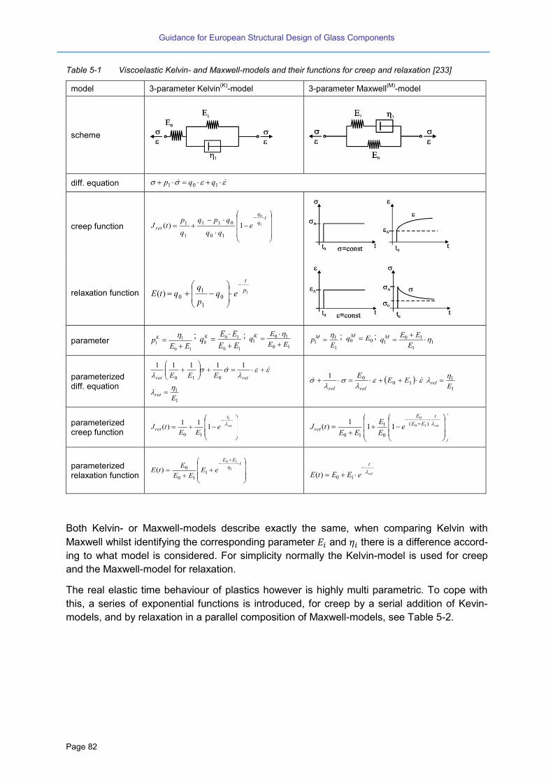
Guidance for European Structural Design of Glass Components
Page 82
Table 5-1 Viscoelastic Kelvin- and Maxwell-models and their functions for creep and relaxation [233]
model 3-parameter Kelvin(K)
-model 3-parameter Maxwell(M)
-model
scheme
diff. equation 101 qqp
creep function
tq
q
ret eqq
qpq
q
ptJ 1
0
1)(
10
011
1
1
relaxation function 1
0
1
10)(
p
t
eqp
qqtE
parameter 10
11
EEpK
;
10
100
EE
EEqK
;
10
101
EE
EqK
1
11
EpM
; 00 EqM ;
11
101
E
EEqM
parameterized diff. equation
retret EEE
11111
010
1
1
Eret
1001
EEE
relrel 1
1
Erel
parameterized creep function
ret
t
ret eEE
tJ
1
111
)(10
ret
t
EE
E
ret eE
E
EEtJ
)(
0
1
10
10
0
111
)(
parameterized relaxation function
t
EE
eEEE
EtE 1
10
110
0)(
rel
t
eEEtE
10)(
Both Kelvin- or Maxwell-models describe exactly the same, when comparing Kelvin with
Maxwell whilst identifying the corresponding parameter and there is a difference accord-
ing to what model is considered. For simplicity normally the Kelvin-model is used for creep
and the Maxwell-model for relaxation.
The real elastic time behaviour of plastics however is highly multi parametric. To cope with
this, a series of exponential functions is introduced, for creep by a serial addition of Kevin-
models, and by relaxation in a parallel composition of Maxwell-models, see Table 5-2.
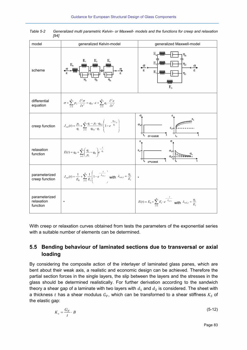
Guidance for European Structural Design of Glass Components
Page 83
Table 5-2 Generalized multi parametric Kelvin- or Maxwell- models and the functions for creep and relaxation [94]
model generalized Kelvin-model generalized Maxwell-model
scheme
differential equation i
in
i
ii
in
i
it
qqt
p
1
0
1
creep function
n
i
tq
q
ii
iiiret
i
i
eqq
qpq
q
ptJ
1 ,0
,0
1
1
,0
1)(
relaxation function
iq
tn
i i
i eqp
qqtE
1
00)(
parameterized creep function
n
i
t
iret
ireteEE
tJ10
,111
)(
with i
iiret
E
,
*
parameterized relaxation function
*
n
i
t
iireleEEtE
1
0,)(
with
i
iirel
E
,
With creep or relaxation curves obtained from tests the parameters of the exponential series
with a suitable number of elements can be determined.
5.5 Bending behaviour of laminated sections due to transversal or axial
loading
By considering the composite action of the interlayer of laminated glass panes, which are
bent about their weak axis, a realistic and economic design can be achieved. Therefore the
partial section forces in the single layers, the slip between the layers and the stresses in the
glass should be determined realistically. For further derivation according to the sandwich
theory a shear gap of a laminate with two layers with and is considered. The sheet with
a thickness has a shear modulus , which can be transformed to a shear stiffness KS of
the elastic gap:
Bt
GK F
s (5-12)
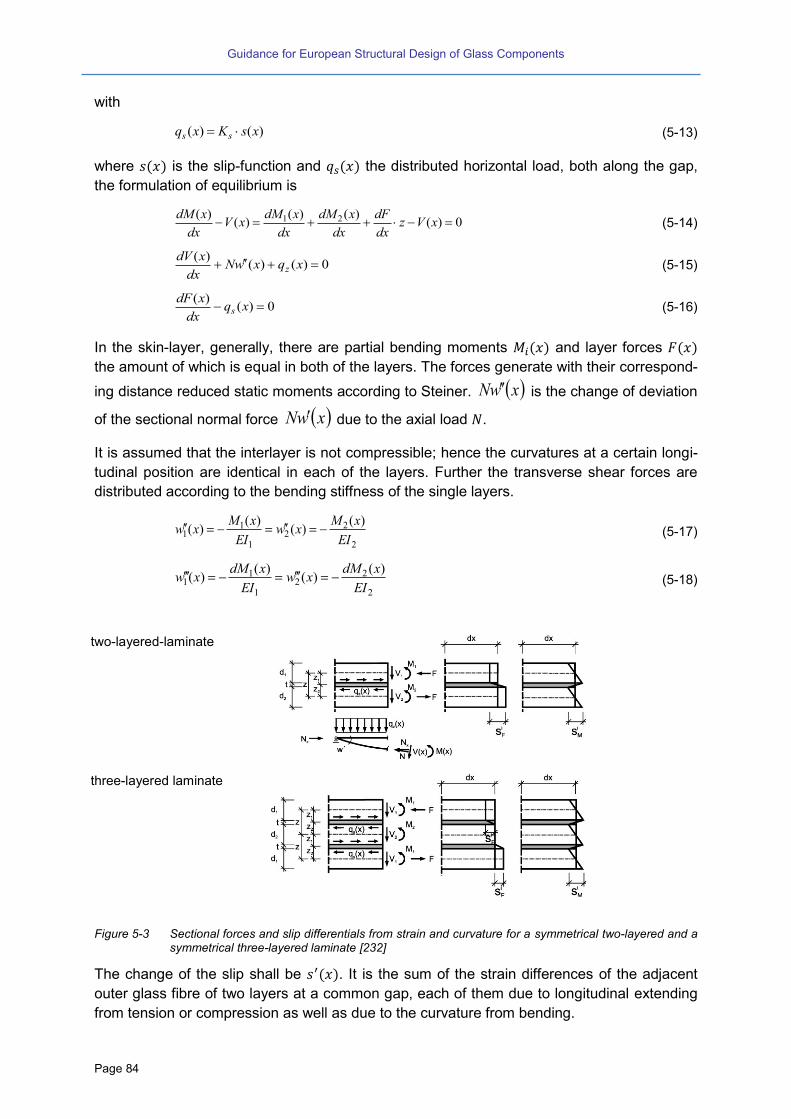
Guidance for European Structural Design of Glass Components
Page 84
with
)()( xsKxq ss (5-13)
where is the slip-function and the distributed horizontal load, both along the gap,
the formulation of equilibrium is
0)()()(
)()( 21 xVz
dx
dF
dx
xdM
dx
xdMxV
dx
xdM (5-14)
0)()()(
xqxwNdx
xdVz (5-15)
0)()(
xqdx
xdFs (5-16)
In the skin-layer, generally, there are partial bending moments and layer forces
the amount of which is equal in both of the layers. The forces generate with their correspond-
ing distance reduced static moments according to Steiner. xwN is the change of deviation
of the sectional normal force xwN due to the axial load .
It is assumed that the interlayer is not compressible; hence the curvatures at a certain longi-
tudinal position are identical in each of the layers. Further the transverse shear forces are
distributed according to the bending stiffness of the single layers.
2
22
1
11
)()(
)()(
EI
xMxw
EI
xMxw (5-17)
2
22
1
11
)()(
)()(
EI
xdMxw
EI
xdMxw (5-18)
two-layered-laminate
three-layered laminate
Figure 5-3 Sectional forces and slip differentials from strain and curvature for a symmetrical two-layered and a symmetrical three-layered laminate [232]
The change of the slip shall be . It is the sum of the strain differences of the adjacent
outer glass fibre of two layers at a common gap, each of them due to longitudinal extending
from tension or compression as well as due to the curvature from bending.
Guidance for European Structural Design of Glass Components
Page 85
212211
EA
1
EA
1)x(Fz)x(wz)x(w)x(s (5-19)
212211
EA
1
EA
1
dx
)x(dFz)x(wz)x(w)x(s (5-20)
21
1
1 EA
1
EA
1
dx
)x(dFz
dx
)x(dM
EI
1)x(s (5-21)
After some algebraic steps it follows:
2121
11)())()(()(
EAEAxqzxqxV
EIEI
zxs ss (5-22)
Further differentiating leads to the general non-homogeneous slip-differential-equation.
)()(
)()11
()(
)()11
(1
)(
2121212
2121
2
xqIIE
zxs
AAIIE
KN
xsKAAII
zKN
Exs
zs
ss
(5-23)
5.6 Bending behaviour of laminated sections due to transversal loading
without axial load
In case the equation from (5-23) is reduced and after integrating two times the gener-
ally known slip-differential-equation of second order comes out to
)()()( 2 xVxsxs (5-24)
with
2121
22 11
AAII
z
E
Ks and )( 21 IIE
z
(5-25)
For the shear gap of a symmetrical 3 layered laminate , and are according to Figure
5-3 and/or Table 5-3.
For the slip differential equation the homogeneous solution can be determined from the
characteristic equation
022 and 2,1 (5-26)
and
xxH eCeCxs
21)( (5-27)
The particular solution is
)()(2
xVxsp
(5-28)
)()()( xsxsxs PH (5-29)
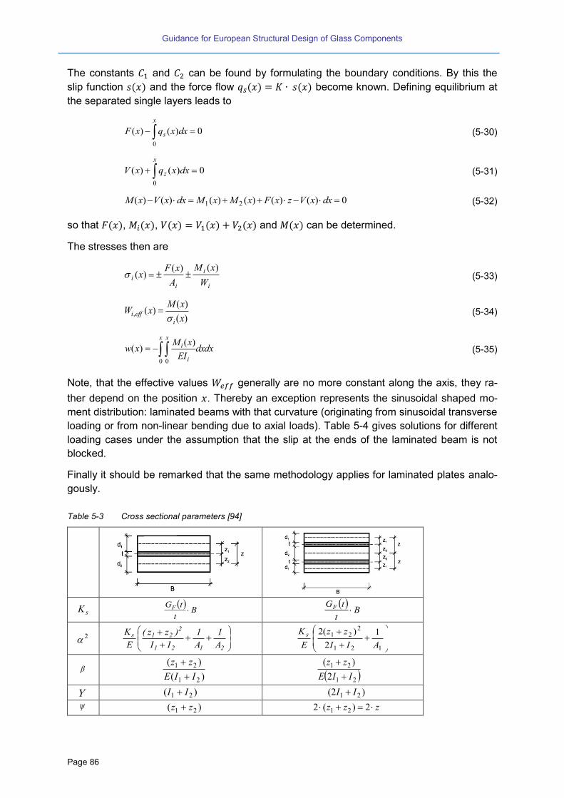
Guidance for European Structural Design of Glass Components
Page 86
The constants and can be found by formulating the boundary conditions. By this the
slip function and the force flow become known. Defining equilibrium at
the separated single layers leads to
0)()(
0
dxxqxF
x
s (5-30)
0)()(
0
dxxqxV
x
z (5-31)
0)()()()()()( 21 dxxVzxFxMxMdxxVxM (5-32)
so that , , and can be determined.
The stresses then are
i
i
ii
W
xM
A
xFx
)()()( (5-33)
)(
)()(,
x
xMxW
ieffi
(5-34)
dxdxEI
xMxw
x x
i
i
0 0
)()( (5-35)
Note, that the effective values generally are no more constant along the axis, they ra-
ther depend on the position . Thereby an exception represents the sinusoidal shaped mo-
ment distribution: laminated beams with that curvature (originating from sinusoidal transverse
loading or from non-linear bending due to axial loads). Table 5-4 gives solutions for different
loading cases under the assumption that the slip at the ends of the laminated beam is not
blocked.
Finally it should be remarked that the same methodology applies for laminated plates analo-
gously.
Table 5-3 Cross sectional parameters [94]
sK
Bt
tGF
Bt
tGF
2
2121
221s
A
1
A
1
II
)zz(
E
K
121
221 1
2
)(2
AII
zz
E
K s
)(
)(
21
21
IIE
zz
21
21
2
)(
IIE
zz
)( 21 II )2( 21 II
)( 21 zz zzz 2)(2 21

Guidance for European Structural Design of Glass Components
Page 87
Table 5-4 Overview of the slip and sectional functions and forces for different load cases, free slip at the ends [94]
loading 1 loading 2
static system
homogenous solution
sH characteristic equation: 2,1
22 0 xxH eCeCxs 21
slip function
s(x)
2cosh
2cosh
12
1
2 L
Lx
P 1,21, sinh
)cosh(
sinh)( III x
ba
bPxs
)(cosh
)cosh(
cosh1)( 1,21, bx
ba
aPxs IIIIII
slip distribution
m(x1)
2cosh
2sinh
22
1
12 L
Lx
Lx
Ks
b
ba
bxKm
IsI
))(cosh(
)sinh()cosh( 1,
2
))(cosh(
))(sinh()cosh( 1,1,2 ba
bxabx
Km
IIII
sII
)( 1, xW effi
mxLd
dB
m
xL
i
i
242
4
)2(
1
1
)(2
)( 1,,,
Ii
i
I
IIeffi
mbd
dB
m
bxW
)(2
)(
1,1
1,1,,,
IIIIi
II
IIIIIIeffi
mxbd
dB
m
xbxW
)( 1xF mP III mPxF )( 1,
IIIIII mPxF )( 1,
)( 1xMi
m
xLP i
24
1 I
iIIi mb
PxM
)( 1,,
IIIIi
IIIIi mxbP
xM
1,1,, )(
)( 1xM
24)()( 1
11
xLPxFxM i
bPxFxMxM IIiII )()()( 1,1,1,
)(
)()()(
1,
1,1,1,
II
IIIIiIII
xbP
xFxMxM
)( 1x )(
)(
1,
1
xW
xM
effi
)(
)(;
)(
)(max
1,,
1,
1,,
1,
IIeffi
II
Ieffi
I
xW
xM
xW
xM

Guidance for European Structural Design of Glass Components
Page 88
Table 5-5 Continuation of the Table 5-4 [94]
Loading 3 Loading 4
static system
homogenous solution sH
characteristic equation: 2,122 0
xxH eCeCxs 21
L
x
L
x
H eCeCxs
21
slip function s(x)
1
1121
2cosh
)sinh(
xL
xx
qxs
L
x
L
Vxs z
cos
22
slip distribution
)( 1xm
2cosh
)cosh(1
82 2
1
2
221
2 L
xLxKs
22
L
Ks
)( 1, xW effi
mxLd
dB
m
xL
i
i
282
8
)4(2
1
2
2
1
2
)1(
2
1
md
dB
m i
i
)( 1xF mq
L
xLmVz
sin
)( 1xMi
m
xLq i
28
21
2 m
L
x
LV iz
1sin
)( 1xM
28)()(
21
2
11
xLqxFxM i
L
xLVxFxM zi
sin)()(
)( 1x )(
)(
1,
1
xW
xM
effi
)(
)(
, xW
xM
effi
Further methods to calculate the stresses and deformations in glass sandwich structures can
be found in the literature [165] [166] [168].
5.7 Post-glass breakage strength of laminated glass
The fail-safe approach to structural glass design should include that, due to an unforeseen
event (accidental loads, vandalism, etc.), glass components can fragment in whole or in part.
Thus, it has to be checked that for this limit condition the element maintains a load-bearing
capacity sufficient to cope with permanent loads, together with part of the variable loads. It is
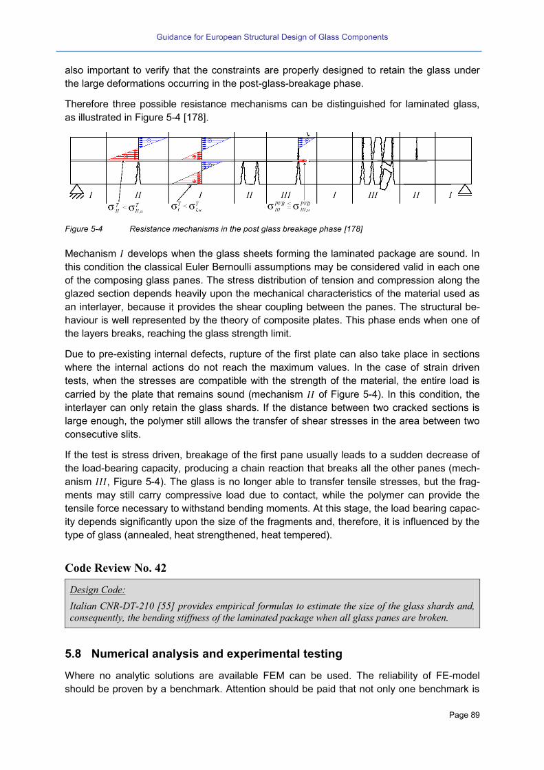
Guidance for European Structural Design of Glass Components
Page 89
also important to verify that the constraints are properly designed to retain the glass under
the large deformations occurring in the post-glass-breakage phase.
Therefore three possible resistance mechanisms can be distinguished for laminated glass,
as illustrated in Figure 5-4 [178].
Figure 5-4 Resistance mechanisms in the post glass breakage phase [178]
Mechanism develops when the glass sheets forming the laminated package are sound. In
this condition the classical Euler Bernoulli assumptions may be considered valid in each one
of the composing glass panes. The stress distribution of tension and compression along the
glazed section depends heavily upon the mechanical characteristics of the material used as
an interlayer, because it provides the shear coupling between the panes. The structural be-
haviour is well represented by the theory of composite plates. This phase ends when one of
the layers breaks, reaching the glass strength limit.
Due to pre-existing internal defects, rupture of the first plate can also take place in sections
where the internal actions do not reach the maximum values. In the case of strain driven
tests, when the stresses are compatible with the strength of the material, the entire load is
carried by the plate that remains sound (mechanism of Figure 5-4). In this condition, the
interlayer can only retain the glass shards. If the distance between two cracked sections is
large enough, the polymer still allows the transfer of shear stresses in the area between two
consecutive slits.
If the test is stress driven, breakage of the first pane usually leads to a sudden decrease of
the load-bearing capacity, producing a chain reaction that breaks all the other panes (mech-
anism , Figure 5-4). The glass is no longer able to transfer tensile stresses, but the frag-
ments may still carry compressive load due to contact, while the polymer can provide the
tensile force necessary to withstand bending moments. At this stage, the load bearing capac-
ity depends significantly upon the size of the fragments and, therefore, it is influenced by the
type of glass (annealed, heat strengthened, heat tempered).
Code Review No. 42
Design Code:
Italian CNR-DT-210 [55] provides empirical formulas to estimate the size of the glass shards and,
consequently, the bending stiffness of the laminated package when all glass panes are broken.
5.8 Numerical analysis and experimental testing
Where no analytic solutions are available FEM can be used. The reliability of FE-model
should be proven by a benchmark. Attention should be paid that not only one benchmark is

Guidance for European Structural Design of Glass Components
Page 90
sufficient, it should be rather be proven by several benchmark showing different stress
states.
In order to obtain reliable and safe sided numerical results it is necessary to use complex
non-linear time-dependent finite element models (including material and geometrical non-
linearity). Those models must be able to take into account a wide range of specific aspects of
glass structures, such as: the brittle nature of glass, the slenderness of glass elements, the
viscoelastic and time-dependent behaviour of the interlayers, the interface properties, the
existence of point supports and adhesive joints, the existence of residual stresses and stress
gradients, etc.
A full specification of the requirements of a proper numerical analysis is not within the scope
of this report. However, some general recommendations can be stated as follows:
Results should be consolidated and not depending on a further refinement (i.e. there are
prior model congruence investigations).
As far as they have a potential negative influence on the corresponding load and design situ-
ation, all restraints from boundary conditions and loading should be considered. As far as the
influences are potentially positive on the corresponding load and design situation they have
to be neglected.
The element mesh must be sufficiently refined in order to achieve an acceptable accu-
racy and to ensure that the obtained results do not depend on a further refinement;
The elements and integration rules used must realise the local and global behaviour of
the structure;
All relevant effects from the detailing and tolerances should be taken into account;
Constraint relations are necessary to guarantee the displacement compatibility at the
nodes and, preferably, along the element edges when adjacent elements are of differ-
ent types, material or thickness;
Proper support constraints must be imposed with special attention to nodes on sym-
metry axes.
Only a deliberate use of an appropriate model will make possible the full understanding of
the structural response and the derivation of a comprehensive set of rational rules for the
design of those structural elements.
The experimental test setups and procedures must be properly defined in order to obtain
realistic and valuable results. To assure the reproducibility of those experiments or to make
possible their simulation by numerical models, special attention must be paid to the strate-
gies of displacement and force control and to the documentation of the main characteristics
of the sensors, transducers and acquisition data systems used.
To conclude, there is an urgent and unequivocal need of promoting guidelines of best prac-
tise for both numerical analysis and experimental tests and for disseminating reliable results
and benchmarks.

Guidance for European Structural Design of Glass Components
Page 91
Eurocode Outlook No. 23
(1) Apart from rules for the supplication of FEM the Eurocode should give best practice exam-
ples for both numerical analysis and experimental tests as well for reliable results and
benchmarks.
(2) Since this matter is still under research, the scientific discussion is not yet finalized. There-
fore, it should be treated with appropriate care. Thus any respective guidelines in the Euro-
code, for the first instance, should be informative.

Guidance for European Structural Design of Glass Components
Page 92

Guidance for European Structural Design of Glass Components
Page 93
6 Design of secondary structural glass components
6.1 Calculation of monolithic plates
The calculation of the stresses and deflections can be done with the linear plate theory (FEM
or tables); it is allowed to take account of the non-linear theory. The stress values to be de-
termined are the maximum principal stresses.
If the deflections exceed the thickness of the plate then the non-linear effect gets significant
for a glass panel with four supported edges as described, the effect vanishes for a length-to-
width-ratio of more than 3:1 and finally there is no non-linear effect anymore for a glass panel
supported linear at two opposite edges. However, in the first instance it is not always neces-
sary to choose the non-linear theory.
Thermally strengthened glass panels may have holes or cuttings. These have to be carefully
modelled with FEM to take into account the stress concentration in these regions.
6.2 Consideration of the shear bond of laminated glass panels
The static behaviour of a laminated glass panel depends on the stiffness of the interlayer and
the size of the glass panel. The stiffening effect is higher in case of large and thin glass pan-
els and lower in case of small and thick glass panels. As described in chapter 2.2 the materi-
al properties of PVB or other interlayers depend on the loading time and the temperature.
The statically stiffness value of the interlayer can be assumed as constant for a fixed loading
time at a defined temperature.
A precise calculation of laminated glass usually requires the (numerical) solution of differen-
tial equations. In numerical computations, it can be modelled conveniently by layered shell
elements that take into account the dependent stiffness between glass and interlayer, but
most of the commercial numerical codes do not contain such elements. On the other hand, a
full 3-D analysis is complicated and time consuming. This is why, in the design practice and
especially in the preliminary design, it is very useful to consider approximate methods for the
calculation of laminated glass. The common practical approach is the definition of the deflec-
tion- and stress-effective thickness: That is the (constant) thickness of a homogeneous
beam/plate that, under the same boundary and loading conditions of the considered situa-
tion, presents the same bending behaviour in terms of stresses and deflection, respectively.
The existing design codes are dealing in different ways with the shear stiffness of the inter-
layer (Code Review No. 39). On the one hand there are different philosophies concerning the
material properties, on the other hand there are various conflicting calculation methods.
Further references to this topic can be found in (e.g. [179]).

Guidance for European Structural Design of Glass Components
Page 94
Code Review No. 43
Design standards:
DIN 18008 [44]: The shear stiffness of the interlayer is neglected in the current DIN 18008. Thus
for the static verification a laminated glass panel is calculated assuming as independent single lay-
ers not being connected to each other. Only in case of the simulation of an impact load a full shear
bond can be taken into account.
prEN 16612 [37]: The overall glass thickness is substituted by an effective thickness that takes into
account the laminated effect by using a shear transfer factor . This shear transfer factor refers to a
glass panel size of 3000 mm x 2000 mm supported at the four edges [22]. The shear transfer factor
is depending on the load duration.
NEN 2608 [45]: The thickness of the laminated glass is substituted by an effective thickness, but the
used shear transfer factor is depending on the size of the glass panel, bearing conditions, load con-
figurations and the load duration.
ÖNORM B 3716 [48]: For short loading time like winds loads a value of G = 0.4 N/mm² for PVB-
sheets is accepted. The value is also used for FEM calculation with sandwich elements.
Technical recommendation: CNR-DT-210 [55]: Italian CNR-DT-210 provides very accurate formu-
las for the evaluation of the deflection- and stress-effective thickness for both laminated glass beams
and plates, accounting for the boundary/ loading condition and size effect.
Technical Approvals (e.g. [78]): Here, the shear stiffness value G is given depending on the type of
loading (wind, horizontal traffic loading, snow and dead load). The shear stiffness can be used for
the FEM with sandwich elements that can cover the mechanical properties of the interlayer. Fur-
thermore, theoretical solutions like the sandwich theory or the extended bending and torsional theo-
ry exist.
Whereas the positive effect (increasing of the bending resistance) of the shear stiffness is to be ne-
glected (e.g. [44]), the negative effect of the shear stiffness (increasing of the effective climatic load-
ing of insulating glass panels due to bending stiffness increase) must always be taken into account.
Eurocode Outlook No. 24
(1) As described in chapter 5.5 and 5.6 the effective value Weff is not constant over the plate.
Therefore the simplified methods using a shear factor should be analysed in view of an
accepted method for a simplified design.
(2) The consideration of the interlayer stiffness should be allowed in case a value of Ginterlayer
can be given fulfilling the requirements of EN 1990 on the reliability. The interlayer stiff-
ness should also be determined in dependence on the load distribution and the ambient
temperature in combination with the load duration.
(3) Eurocode should enable both quasi-static and transient FEM calculations based on me-
chanical models.
6.3 Insulating glass plates
Due to the enclosed air cavity between the single glasses an additional loading has to be
taken into account for the design of insulating glass units. The so-called climatic loading acts
as an inner load due to the change of temperature or of the air pressure and the difference of
altitude in relation of the place of production and installation (e.g. [145]), see Figure 6-1.
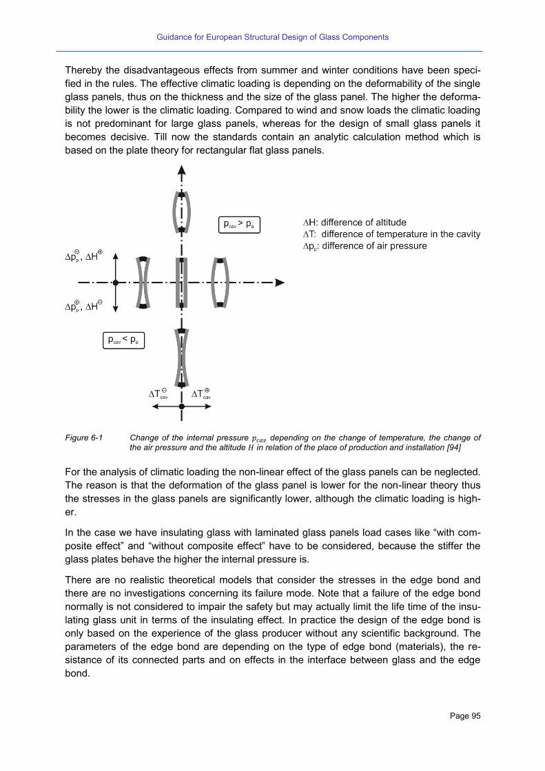
Guidance for European Structural Design of Glass Components
Page 95
Thereby the disadvantageous effects from summer and winter conditions have been speci-
fied in the rules. The effective climatic loading is depending on the deformability of the single
glass panels, thus on the thickness and the size of the glass panel. The higher the deforma-
bility the lower is the climatic loading. Compared to wind and snow loads the climatic loading
is not predominant for large glass panels, whereas for the design of small glass panels it
becomes decisive. Till now the standards contain an analytic calculation method which is
based on the plate theory for rectangular flat glass panels.
Figure 6-1 Change of the internal pressure depending on the change of temperature, the change of
the air pressure and the altitude in relation of the place of production and installation [94]
For the analysis of climatic loading the non-linear effect of the glass panels can be neglected.
The reason is that the deformation of the glass panel is lower for the non-linear theory thus
the stresses in the glass panels are significantly lower, although the climatic loading is high-
er.
In the case we have insulating glass with laminated glass panels load cases like “with com-
posite effect” and “without composite effect” have to be considered, because the stiffer the
glass plates behave the higher the internal pressure is.
There are no realistic theoretical models that consider the stresses in the edge bond and
there are no investigations concerning its failure mode. Note that a failure of the edge bond
normally is not considered to impair the safety but may actually limit the life time of the insu-
lating glass unit in terms of the insulating effect. In practice the design of the edge bond is
only based on the experience of the glass producer without any scientific background. The
parameters of the edge bond are depending on the type of edge bond (materials), the re-
sistance of its connected parts and on effects in the interface between glass and the edge
bond.
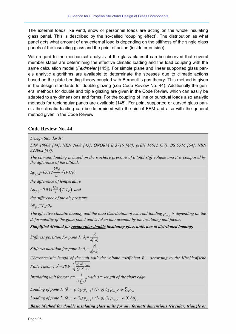
Guidance for European Structural Design of Glass Components
Page 96
The external loads like wind, snow or personnel loads are acting on the whole insulating
glass panel. This is described by the so-called “coupling effect”. The distribution as what
panel gets what amount of any external load is depending on the stiffness of the single glass
panels of the insulating glass and the point of action (inside or outside).
With regard to the mechanical analysis of the glass plates it can be observed that several
member states are determining the effective climatic loading and the load coupling with the
same calculation model (Feldmeier [145]). For simple plane and linear supported glass pan-
els analytic algorithms are available to determinate the stresses due to climatic actions
based on the plate bending theory coupled with Bernoulli’s gas theory. This method is given
in the design standards for double glazing (see Code Review No. 44). Additionally the gen-
eral methods for double and triple glazing are given in the Code Review which can easily be
adapted to any dimensions and forms. For the coupling of line or punctual loads also analytic
methods for rectangular panes are available [145]. For point supported or curved glass pan-
els the climatic loading can be determined with the aid of FEM and also with the general
method given in the Code Review.
Code Review No. 44
Design Standards:
DIN 18008 [44], NEN 2608 [45], ÖNORM B 3716 [48], prEN 16612 [37], BS 5516 [54], NBN
S23002 [49]:
The climatic loading is based on the isochore pressure of a total stiff volume and it is composed by
the difference of the altitude
p 0
0.012kPa
m P
the difference of temperature
pT 0 0.0
kPa
K (T-TP) and
the difference of the air pressure
pp 0 p
a p
P
The effective climatic loading and the load distribution of external loading pe i
is depending on the
deformability of the glass panel and is taken into account by the insulating unit factor.
Simplified Method for rectangular double insulating glass units due to distributed loading:
Stiffness partition for pane 1: 1 d1
d1 d2
Stiffness partition for pane 2: 2 d2
d1 d2
Characteristic length of the unit with the volume coefficient BV according to the Kirchhoffsche
Plate Theory: a 28 √da di
da di
dcav
B
Insulating unit factor: 1
1 (a
a ) with a = length of the short edge
Loading of pane 1: ( 1 2) pe 1 (1- ) 2 pe 2- ∑ p
i 0
Loading of pane 2: ( 1 2) pe 1 (1- ) 2 pe 2 ∑ p
i 0
Basic Method for double insulating glass units for any formats dimensions (circular, triangle or
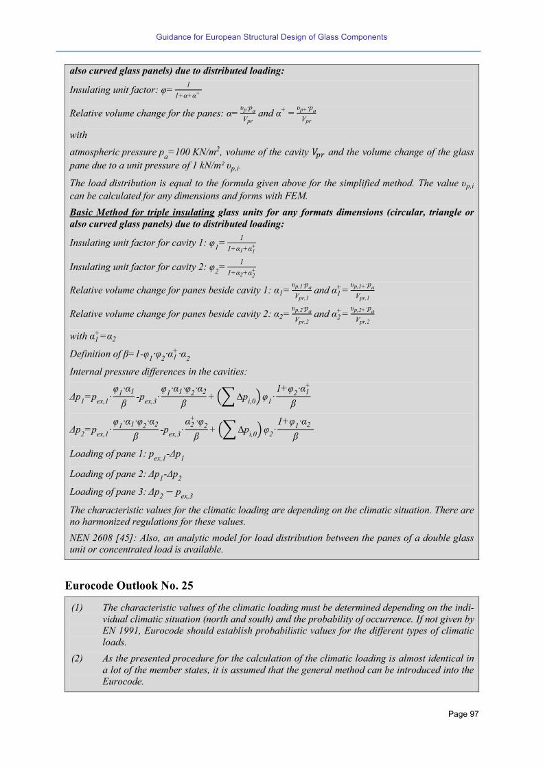
Guidance for European Structural Design of Glass Components
Page 97
also curved glass panels) due to distributed loading:
Insulating unit factor: 1
1
Relative volume change for the panes: p pa
pr and
p pa
pr
with
atmospheric pressure pa 100 KN m2, volume of the cavity and the volume change of the glass
pane due to a unit pressure of 1 kN/m² p i.
The load distribution is equal to the formula given above for the simplified method. The value p i
can be calculated for any dimensions and forms with FEM.
Basic Method for triple insulating glass units for any formats dimensions (circular, triangle or
also curved glass panels) due to distributed loading:
Insulating unit factor for cavity 1: 1
1
1 1 1
Insulating unit factor for cavity 2: 2
1
1 2 2
Relative volume change for panes beside cavity 1: 1 p 1 pa
pr 1 and 1
p 1 pa
pr 1
Relative volume change for panes beside cavity 2: 2 p 2 pa
pr 2 and 2
p 2 pa
pr 2
with 1 2
Definition of 1- 1
2 1
2
Internal pressure differences in the cavities:
p1 p
e 1 1 1
p
e 1 1 2 2
(∑ p
i 0)
1 1
2 1
p2 p
e 1 1 1 2 2
p
e 2
2
(∑ p
i 0)
2 1
1 2
Loading of pane 1: pe 1
- p1
Loading of pane 2: p1- p
2
Loading of pane 3: p2 p
e
The characteristic values for the climatic loading are depending on the climatic situation. There are
no harmonized regulations for these values.
NEN 2608 [45]: Also, an analytic model for load distribution between the panes of a double glass
unit or concentrated load is available.
Eurocode Outlook No. 25
(1) The characteristic values of the climatic loading must be determined depending on the indi-
vidual climatic situation (north and south) and the probability of occurrence. If not given by
EN 1991, Eurocode should establish probabilistic values for the different types of climatic
loads.
(2) As the presented procedure for the calculation of the climatic loading is almost identical in
a lot of the member states, it is assumed that the general method can be introduced into the
Eurocode.
Guidance for European Structural Design of Glass Components
Page 98
6.4 Linearly supported glazing
The most glass panels are linearly supported at the glass edges. They are assembled to
sub-structures which can be
Windows with frames made of wood, plastics, steel or aluminium
Rail-post structured facades
Curtain walls
Structural sealant glazing
Roof structures, etc.
The glass panels can be supported linearly at the four edges, at three edges or at two oppo-
site edges. A hybrid support-system is possible in terms of four linearly supported edges for
pressure loads and two linearly supported edges for suction loads.
For indoor applications very heavy glass panels (like glass floors) may solely be supported
against pressure loads disregarding any suction loads (chapter 6.5.4).
Normally the glass panels are simply clamped at the edges. In case of structural sealant
glazing the glass panels are connected to an adapter frame. The adhesive connection is
made of a silicone sealant.
In-plane loading should be avoided; moreover the in-plane support conditions should be stat-
ically determined. The glass panels are mainly loaded by perpendicular loads like self-
weight, wind or snow loads, climatic loading or personal loading (balustrade or floors).
The type of glazing can be:
Monolithic glass panels
Laminated glass panels
Insulating glass panels combining either of two the types mentioned above
All flat or curved products of glazing above can be used for linear supported glass panels.
The support conditions are assumed fixed perpendicular to the glass plate if the deflection of
the substructure is limited to 200 related to the length of the panel. Larger deflections of the
substructure can be treated like “Cold deflection” of glass panels, mechanically similar to
settlement displacements.
Curved glass panels show much lower stresses caused by outer loading due to the high ge-
ometrical stiffness compared to flat glass panels. In case of curved insulating glass units the
high stiffness and the associated low deformability lead to a very high effective climatic load-
ing and have to be taken into account properly. Whereas for flat glass the limiting value for a
“stiff” substructure can be fixed to 200, the situation for curved glass is different because
small deflections of the substructure induce high stresses in a curved glass panel. This is
one of the reasons why several national design codes are non-applicable for curved glass
panels.
The necessary edge cover of the linear support is varying depending on the type of glazing
(monolithic or insulating glass panel), the size of the glass panel and the robustness re-
quirements. E.g. the edge cover can be 7 up to 15 mm, while these values are purely empiri-
cal. An upper limit of the edge cover is recommended to avoid high stress gradients in a
glass plate because the covered parts at the edges may cause a temperature and stress

Guidance for European Structural Design of Glass Components
Page 99
gradient. Hereby, the glass edge resistance (zone 2) determines the resistance of glass
against thermal stresses. There are different methods in Europe to deal with this problem.
For critical situations (high thermal absorption of the glass, etc.) as a deemed to satisfy rec-
ommendation a thermal tempered glass should be used unless sophisticated calculation
methods open solutions for other glass qualities.
For vertical and horizontal glazing without personal loading or impact loading there may be
different constructive requirements to be fulfilled.
For non-broken linear supported glass panels there is a risk of slipping off the glass support if
the deflections exceed a certain value. The limitation of the deflection and a proper control of
the minimum edge cover prevent this scenario.
The standard systems and requirements for balustrades, floors or horizontal glazing accessi-
ble for maintenance are described in the following chapters.
Code Review No. 45
Construction Rules:
DIN 18545 [80]: This execution standard specifies the minimum needed edge covering.
DIN 18008-1 and DIN 18008-2 [44]: The support conditions of a glass plates are assumed to be
fixed out of plane at the edges but free in plane. The limit value such that a stiff substructure can be
assumed may be L/200 along the considered edge.
BS 6262 [60]: Minimum edge cover is recommended for vertical glazing.
BS 5516 [54]: Minimum edge cover is recommended for sloping glazing.
BS 6180 [61]: Minimum edge cover is recommended for barrier infill panes.
prEN 12488 [85]: This European standard gives principal assembly rules for vertical and sloping
glazing. It does not apply e.g. for channel shaped glass, structural sealant glazing, point fixed glaz-
ing, etc..
Code Review No. 46
Design standards:
DIN 18008-2 [44]: Glass types which fulfil the residual resistance requirements:
Vertical glazing: e.g. monolithic glass panels made of heat strengthened or float glass must
be supported at all edges in case of an installation height > 4 m, heat soaked thermally
toughened glass is needed in a case of an installation height > 4 m
Horizontal glazing: e.g. the lower glass panel must be made of laminated glass (only heat
strengthened or float glass layers); limitation of the span for glass panels with only two line-
ar supports < 1,2 m; minimal thickness of the PVB interlayer 0,76 mm,
Application conditions: e.g. minimal edge cover 10 mm, minimum are two opposing linear
supported edges; appropriate setting of the glass panels (number and position of the setting
blocks); limitation of the layer thicknesses ratio (d1 / d2 = 1.5) of the glass laminate
Serviceability Limit State (SLS): For linear supported glass panels the deflection limit (Ser-

Guidance for European Structural Design of Glass Components
Page 100
viceability Limit State is set to L/100. In case of exceeding this limit the verification can be
done by proofing an edge cover after deformation of 5 mm.
Ultimate Limit State (ULS): See
Code Review No. 25
Accidental Scenario for horizontal glass panels: Verification with lower load partial factor for the
failure of one glass panel (accidental design combination)
BS 6262 [60] (vertical glazing) and BS 5516[54] (sloping glazing):
Frames/supports should not deflect more than span/175 (for insulating glass units) or
span/125 (single glazing) in order to be considered as supporting members.
Marked safety glass must be used in locations where human impact is possible.
Sloping overhead glass is required to be an appropriate safety glass (monolithic heat soaked
toughened glass is allowed for low level overhead use).
ULS of the glass from load charts.
SLS: Glass deflection limit span/65 or 50 mm whichever is smaller.
Eurocode Outlook No. 26
(1) Eurocode should give rules on the detailing of linear supports in dependence of the design
situation, scenario and consequence class.
(2) Eurocode should also indicate limits in how far a flexibility of the support-system has to be
taken into account in view of the stress verification of the glass.
6.5 Point fixed glazing
6.5.1 General
Point fixings are widely applied in glass engineering for connecting glass facade or roof pan-
els to the supporting substructure. These point fixings can be located at the edge of the glass
panels or at the surface of the glass panel, see Figure 6-2. Furthermore, the point fixings can
be executed by means of clamping systems, drilled holes, embedded connections or adhe-
sive connections. These point fixing systems are subsequently discussed in the following
sections.

Guidance for European Structural Design of Glass Components
Page 101
Figure 6-2 Types of point fixings
6.5.2 Clamping systems
Point supported glass panels have no linear support at the glass edges; but one possibility
for fixing are punctual clamping systems near the edges. Also combinations of a linear sup-
porting system (e.g. for pressure loads) with a punctual clamping system (e.g. for suction
loads) have been often executed.
Due to the local load introduction stress concentrations near the clamping occur and should
be analysed, the results of which strongly depend on the stiffness of the interfaces.
There are a lot of clamping systems on the market with a European technical approval.
The residual resistance of punctual clamped glass panels is inferior compared to linear sup-
ported glass panels. And also, the risk of slipping off the supports after a glass breakage is
higher. The treatment may be different from country to country.
Code Review No. 47
Design standards:
DIN 18008-3:
Glass types (which fulfil a residual resistance) covering the requirements:
Vertical glazing: Monolithic Glass made of thermally toughened glass (heat soaked, at least
6 mm thick), laminated safety glass made of annealed glass, thermally toughened glass or
heat strengthened glass, insulating glass
Horizontal glazing: Only a combination of linear support for pressure loads and clamping
for suction loads is allowed. Post breakage behaviour must be considered, either by compar-
ing the geometry with already approved geometries or by experiment. Laminated glass made

Guidance for European Structural Design of Glass Components
Page 102
of annealed glass or heat strengthened glass is necessary.
Application conditions: Size of clamping surface at least 1000 mm² and clamping depth at
least 25 mm
Serviceability Limit State (SLS): Calculation of the maximum deflection fmax by appropriate
means, finite element analysis is recommended. Validation of FEM is provided by verification
models. Experimentally determined spring stiffness of the point fixing can be considered. Test
setups are provided in the annex of the standard. Friction between interlaying materials must
not be considered. Cd = 1/100 of the effective span.
Ultimate Limit State (ULS): Point fixing: Calculation of the maximum load capacity on the
basis of technical building regulations, if possible. If not, experimental determination of the
maximum load capacity considering different load directions. Glass: Calculation of the max-
imum tensile stress σmax by appropriate means, FEM is recommended. Validation of FEM is
provided by verification models. Experimentally determined spring stiffness of the clamping
system can be considered. Test setups are provided in the annex of the standard. Friction be-
tween interlaying materials must not be considered.
BS 6180 [61] and BS 6262 [60]: These standards give basic advices on bolted and non-bolted point
fixings.
Eurocode Outlook No. 27
(1) The Eurocode should take into account the design of glazing with punctual clamping sys-
tems.
(2) Thereby the stresses around the clamping have to be assessed by appropriate means like
FEM, analytical procedures or combined methods.
(3) Whilst using FEM, the degree of elements and meshing have to guarantee:
Results are consolidated and do not depend on a further refinement (prior model con-
gruence investigation)
All relevant effects from the detailing and tolerances should be taken into account.
As far as they have a potentially negative influence on the corresponding load and de-
sign situation, all restraints from boundary conditions and loading should be consid-
ered. As far as the influences are potentially positive for the corresponding load and
design situation they have to be neglected.
6.5.3 Point fixings with drilled holes
Compared to clamping systems a drilling is needed to produce the hole and to connect the
point fixing with the glass panel. Depending on the type of point fixing different geometries of
drillings are available, see Figure 6-3.
Thermal pre-stressing is an issue in the borehole area, especially because this area is often
crucial. It must be assured that the level of pre-stress is at least as high as it is in the body. If
not, the design value for load-bearing resistance must be reduced. Optical stress measure-
ments have proven [117] [124] that a sufficient thermal pre-stressing (pressure on the bore-
hole surface) can develop in the hole area for cylindrical and conical holes (depending on the
size of the hole and the distance to the edges).
The more complex the borehole geometry is, the more difficult the proof of sufficient pre-
stress will get. In some cases (e.g. blind hole) optical measurement is impossible with exist-
ing methods and indirect FEM simulations may give an answer, but the results are highly
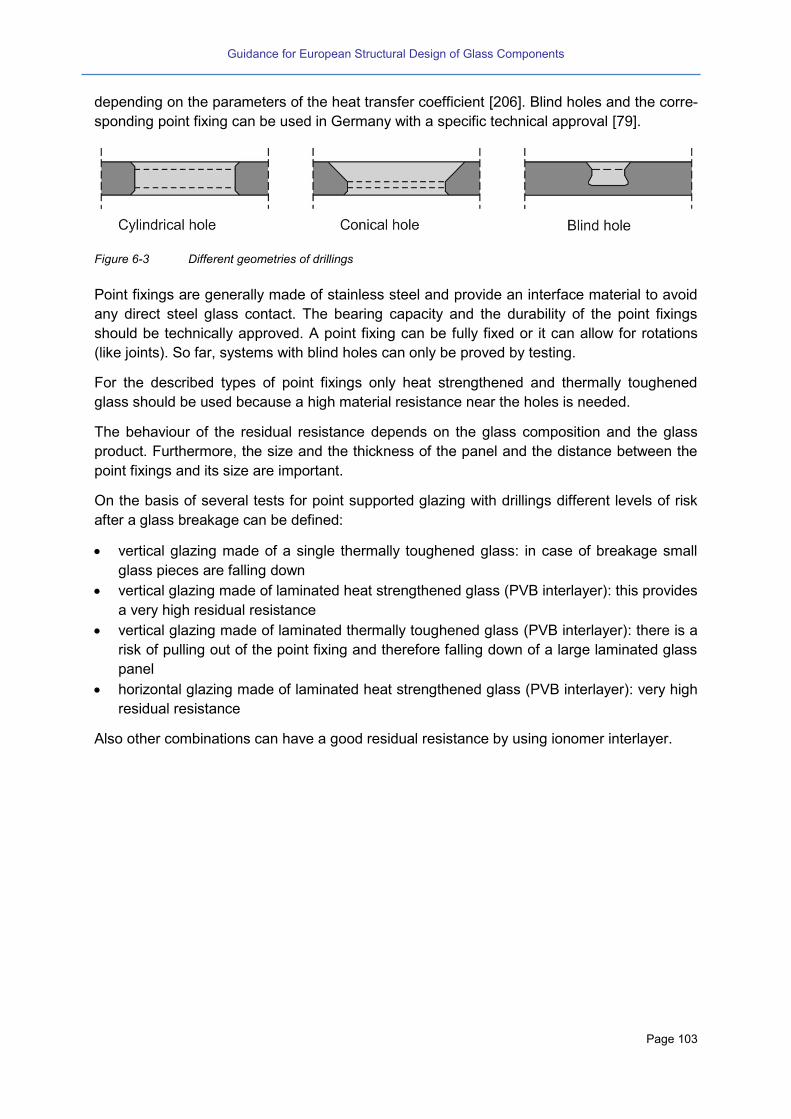
Guidance for European Structural Design of Glass Components
Page 103
depending on the parameters of the heat transfer coefficient [206]. Blind holes and the corre-
sponding point fixing can be used in Germany with a specific technical approval [79].
Figure 6-3 Different geometries of drillings
Point fixings are generally made of stainless steel and provide an interface material to avoid
any direct steel glass contact. The bearing capacity and the durability of the point fixings
should be technically approved. A point fixing can be fully fixed or it can allow for rotations
(like joints). So far, systems with blind holes can only be proved by testing.
For the described types of point fixings only heat strengthened and thermally toughened
glass should be used because a high material resistance near the holes is needed.
The behaviour of the residual resistance depends on the glass composition and the glass
product. Furthermore, the size and the thickness of the panel and the distance between the
point fixings and its size are important.
On the basis of several tests for point supported glazing with drillings different levels of risk
after a glass breakage can be defined:
vertical glazing made of a single thermally toughened glass: in case of breakage small
glass pieces are falling down
vertical glazing made of laminated heat strengthened glass (PVB interlayer): this provides
a very high residual resistance
vertical glazing made of laminated thermally toughened glass (PVB interlayer): there is a
risk of pulling out of the point fixing and therefore falling down of a large laminated glass
panel
horizontal glazing made of laminated heat strengthened glass (PVB interlayer): very high
residual resistance
Also other combinations can have a good residual resistance by using ionomer interlayer.
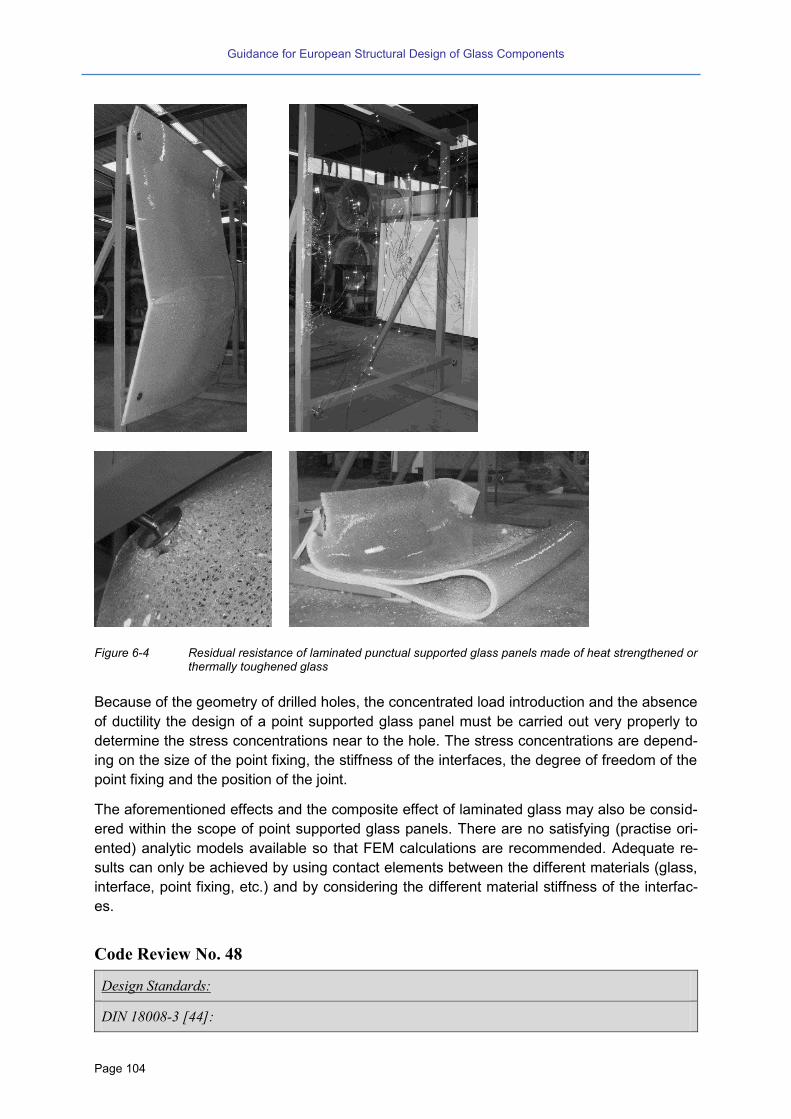
Guidance for European Structural Design of Glass Components
Page 104
Figure 6-4 Residual resistance of laminated punctual supported glass panels made of heat strengthened or thermally toughened glass
Because of the geometry of drilled holes, the concentrated load introduction and the absence
of ductility the design of a point supported glass panel must be carried out very properly to
determine the stress concentrations near to the hole. The stress concentrations are depend-
ing on the size of the point fixing, the stiffness of the interfaces, the degree of freedom of the
point fixing and the position of the joint.
The aforementioned effects and the composite effect of laminated glass may also be consid-
ered within the scope of point supported glass panels. There are no satisfying (practise ori-
ented) analytic models available so that FEM calculations are recommended. Adequate re-
sults can only be achieved by using contact elements between the different materials (glass,
interface, point fixing, etc.) and by considering the different material stiffness of the interfac-
es.
Code Review No. 48
Design Standards:
DIN 18008-3 [44]:
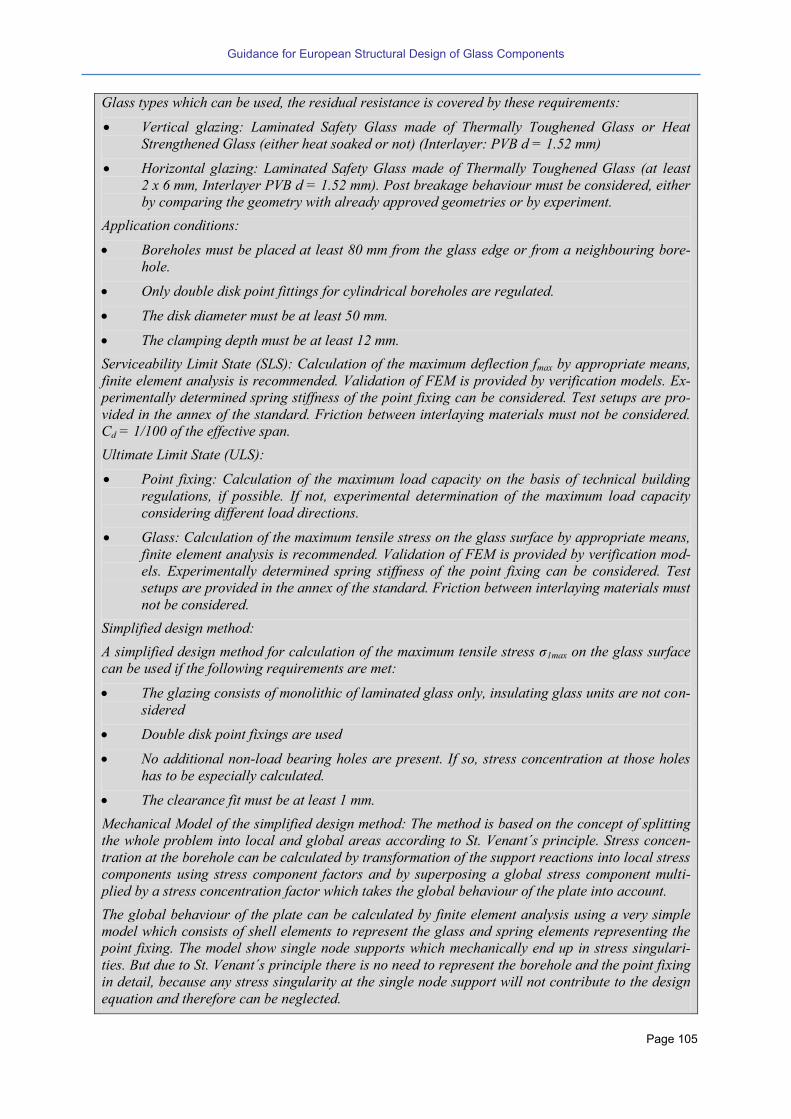
Guidance for European Structural Design of Glass Components
Page 105
Glass types which can be used, the residual resistance is covered by these requirements:
Vertical glazing: Laminated Safety Glass made of Thermally Toughened Glass or Heat
Strengthened Glass (either heat soaked or not) (Interlayer: PVB d = 1.52 mm)
Horizontal glazing: Laminated Safety Glass made of Thermally Toughened Glass (at least
2 x 6 mm, Interlayer PVB d = 1.52 mm). Post breakage behaviour must be considered, either
by comparing the geometry with already approved geometries or by experiment.
Application conditions:
Boreholes must be placed at least 80 mm from the glass edge or from a neighbouring bore-
hole.
Only double disk point fittings for cylindrical boreholes are regulated.
The disk diameter must be at least 50 mm.
The clamping depth must be at least 12 mm.
Serviceability Limit State (SLS): Calculation of the maximum deflection fmax by appropriate means,
finite element analysis is recommended. Validation of FEM is provided by verification models. Ex-
perimentally determined spring stiffness of the point fixing can be considered. Test setups are pro-
vided in the annex of the standard. Friction between interlaying materials must not be considered.
Cd = 1/100 of the effective span.
Ultimate Limit State (ULS):
Point fixing: Calculation of the maximum load capacity on the basis of technical building
regulations, if possible. If not, experimental determination of the maximum load capacity
considering different load directions.
Glass: Calculation of the maximum tensile stress on the glass surface by appropriate means,
finite element analysis is recommended. Validation of FEM is provided by verification mod-
els. Experimentally determined spring stiffness of the point fixing can be considered. Test
setups are provided in the annex of the standard. Friction between interlaying materials must
not be considered.
Simplified design method:
simplified design method for calculation of the ma imum tensile stress σ1max on the glass surface
can be used if the following requirements are met:
The glazing consists of monolithic of laminated glass only, insulating glass units are not con-
sidered
Double disk point fixings are used
No additional non-load bearing holes are present. If so, stress concentration at those holes
has to be especially calculated.
The clearance fit must be at least 1 mm.
Mechanical Model of the simplified design method: The method is based on the concept of splitting
the whole problem into local and global areas according to St. Venant´s principle. Stress concen-
tration at the borehole can be calculated by transformation of the support reactions into local stress
components using stress component factors and by superposing a global stress component multi-
plied by a stress concentration factor which takes the global behaviour of the plate into account.
The global behaviour of the plate can be calculated by finite element analysis using a very simple
model which consists of shell elements to represent the glass and spring elements representing the
point fixing. The model show single node supports which mechanically end up in stress singulari-
ties. But due to St. Venant´s principle there is no need to represent the borehole and the point fixing
in detail, because any stress singularity at the single node support will not contribute to the design
equation and therefore can be neglected.
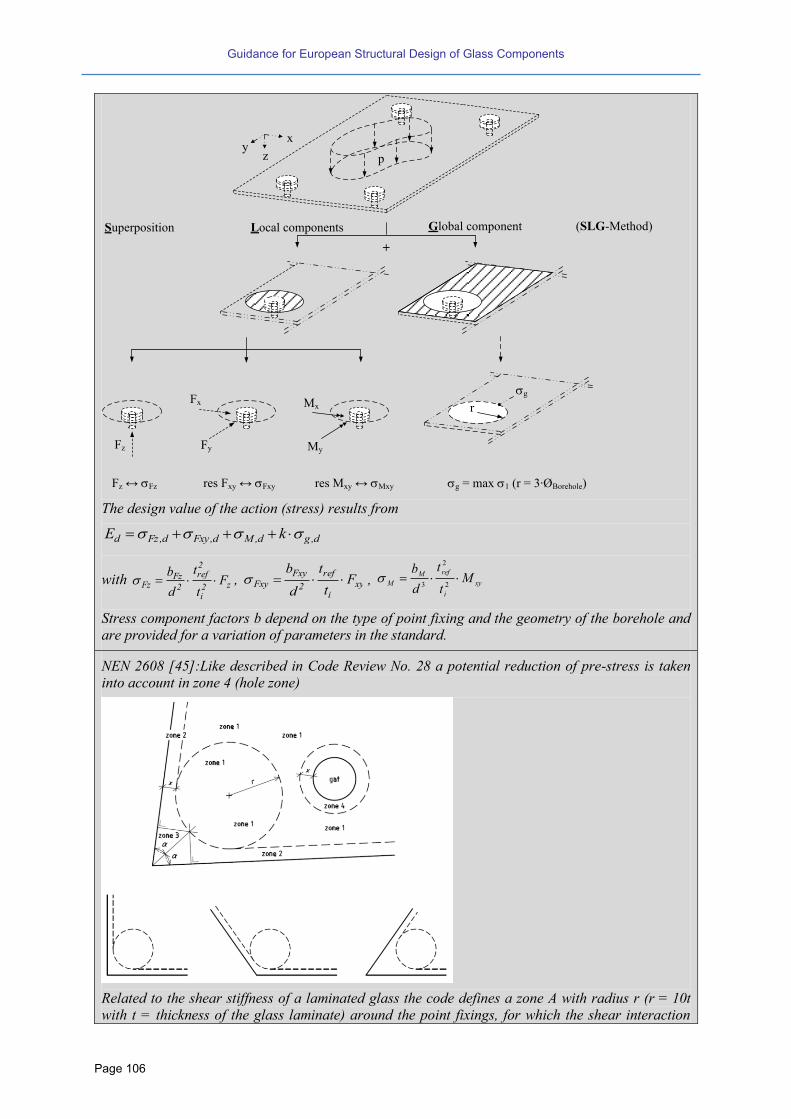
Guidance for European Structural Design of Glass Components
Page 106
The design value of the action (stress) results from
d,gd,Md,Fxyd,Fzd kE
with z2i
2ref
2
FzFz F
t
t
d
b , xy
i
ref
2
FxyFxy F
t
t
d
b , xy
i
refM
M Mt
t
d
b
2
2
3
Stress component factors b depend on the type of point fixing and the geometry of the borehole and
are provided for a variation of parameters in the standard.
NEN 2608 [45]:Like described in Code Review No. 28 a potential reduction of pre-stress is taken
into account in zone 4 (hole zone)
Related to the shear stiffness of a laminated glass the code defines a zone A with radius r (r = 10t
with t = thickness of the glass laminate) around the point fixings, for which the shear interaction
xy
z
Local components Global component
p
Fx
Fz Fy My
Mx
g
+
Superposition (SLG-Method)
Fz ↔ Fz res Fxy ↔ Fxy res Mxy ↔ Mxy g = max 1 (r = 3∙ØBorehole)
r
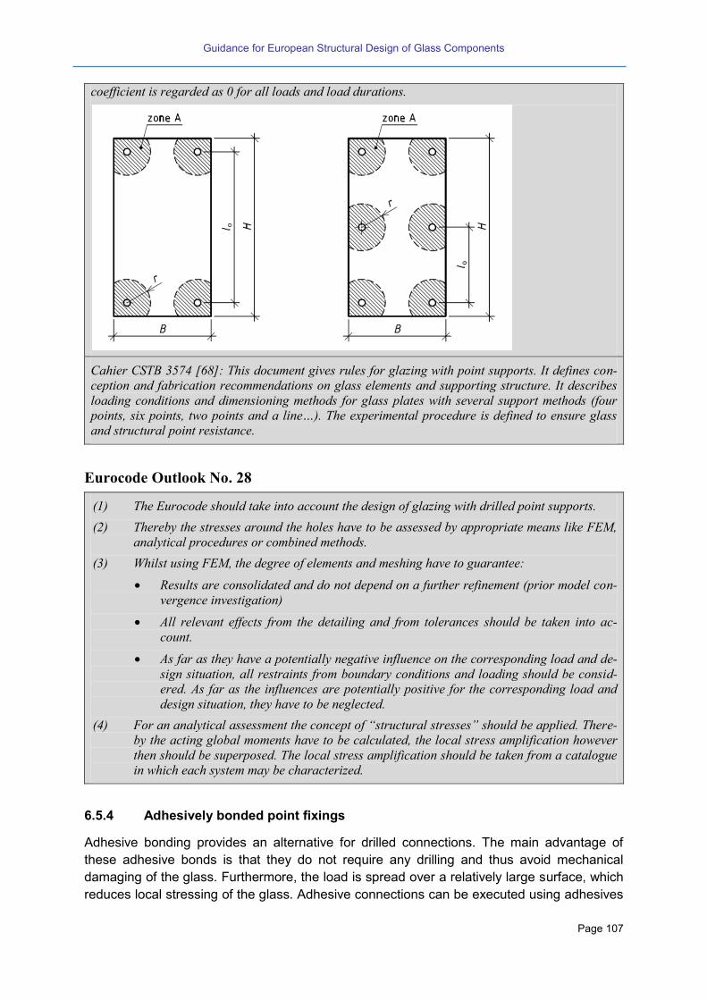
Guidance for European Structural Design of Glass Components
Page 107
coefficient is regarded as 0 for all loads and load durations.
Cahier CSTB 3574 [68]: This document gives rules for glazing with point supports. It defines con-
ception and fabrication recommendations on glass elements and supporting structure. It describes
loading conditions and dimensioning methods for glass plates with several support methods (four
points si points two points and a line…). The e perimental procedure is defined to ensure glass
and structural point resistance.
Eurocode Outlook No. 28
(1) The Eurocode should take into account the design of glazing with drilled point supports.
(2) Thereby the stresses around the holes have to be assessed by appropriate means like FEM,
analytical procedures or combined methods.
(3) Whilst using FEM, the degree of elements and meshing have to guarantee:
Results are consolidated and do not depend on a further refinement (prior model con-
vergence investigation)
All relevant effects from the detailing and from tolerances should be taken into ac-
count.
As far as they have a potentially negative influence on the corresponding load and de-
sign situation, all restraints from boundary conditions and loading should be consid-
ered. As far as the influences are potentially positive for the corresponding load and
design situation, they have to be neglected.
(4) For an analytical assessment the concept of “structural stresses” should be applied. There-
by the acting global moments have to be calculated, the local stress amplification however
then should be superposed. The local stress amplification should be taken from a catalogue
in which each system may be characterized.
6.5.4 Adhesively bonded point fixings
Adhesive bonding provides an alternative for drilled connections. The main advantage of
these adhesive bonds is that they do not require any drilling and thus avoid mechanical
damaging of the glass. Furthermore, the load is spread over a relatively large surface, which
reduces local stressing of the glass. Adhesive connections can be executed using adhesives

Guidance for European Structural Design of Glass Components
Page 108
such as epoxies, acrylates, polyurethanes and silicones. In addition, stiff (ionomer) interlay-
ers and transparent addition cured silicon foil material are currently gaining interest for creat-
ing adhesive connections [125][126]. However, due to the uncertainties about the durability
and long-term behaviour of adhesive connections, their application in practice is currently
limited and additional retaining devices are needed. Further research into adhesively bonded
fixings is thus required. More information is included in chapter 8.4.
6.5.5 Embedded systems
The advent of new ionomere interlayers has had important influence in recent improvements
of glass fixing systems. Embedded solutions based on the combination of the lamination pro-
cess and the assembly of glass fittings have the capability of combining most of the ad-
vantages of available mechanic as well as of adhesive fixing solutions. These systems im-
prove the strength, safety, durability and appearance of frameless laminated glazing, offering
new possibilities especially under severe environmental conditions.
The incorporation of the metallic fitting into the laminated glass, Figure 6-5, improves the
distribution of the applied loads between both glass components of the laminate, giving a
significant increase in load bearing capacity while at the same time reducing the glass thick-
ness required.
The absence of exterior bolts, caps or washers or holes at the external glass surface, allows
the use of a wider variety of glass types. Fixing securely to the inner structural glass compo-
nent of an insulated unit avoids cold-bridging as the external glass surface is not penetrated
with fittings. This results in a more thermally efficient façade.
These high performance laminated systems offer: increased strength and durability; reduced
glass and structure weights; longer spans with reduced fixings; advanced post glass break-
age security; visibly improved clarity; structural glass fin and beam applications.
Figure 6-5 Embedded glass fixing system [127][128]
6.6 Glass Floors
Glass floors are horizontal glazing structures loaded by the self-weight of the glass, rarely
wind or snow loads for outdoor applications and vertical live load. The upper glass layer gets
often treatment to fulfil a certain slip resistant.

Guidance for European Structural Design of Glass Components
Page 109
This type of application is considerably high because of the high risk of a glass breakage due
to falling objects or persons. Code Review No. 49 gives an overview of the requirements in
some national design standards. The loads given in EN 1991 are also indicated in the Re-
view to demonstrate the actual non consistency between the national glass standards and
the European load codes.
Code Review No. 49
Design standards: Requirements concerning floor glass laminate and of its design
DIN 18008-5 [44]:
Glass products: The standard glass composition is consisting of at least three glass layers.
Loading: according to EN 1991-1-1, additional dead load + single load (50 mm x 50 mm)
Design ULS: all glass layers can be taken into account
Design ULS: accidental design scenario
Design SLS: all glass layers can be taken into account, maximal deflection L/200
Residual resistance: test procedure (impact body is the “Torpedo”-impact body = hard impact) or
constructive requirements (e.g. the two bottom glass layers should be float glass or heat strength-
ened glass to fulfil a good residual post failure capacity or resistance, edge covering, minimal glass
thickness and maximal span).
ÖNORM B 3716 [48]:
Glass products: The load carrying layer must be made of a laminated glass with an additional
abrasion layer. Thermally toughened glass is only allowed in combination with float or heat
strengthened glass. The minimal thickness of the PVB-sheet is 0.76 mm.
Loading: according to EN 1991-1-1, additional dead load + single load (category F with 150 mm x
150 mm and category G with 250 mm x 250 mm)
Design ULS: the abrasion layer cannot be taken into account
Design SLS: the abrasion layer cannot be taken into account, maximal deflection L/100
Residual resistance: accidental design scenario
Cahier CSTB 3448 [70]: This document gives rules for glass floors and stairs installation. It defines
conception and fabrication recommendations. It describes the dimensioning method with specific
loads, loading combinations and validation criteria. It gives the calculation method for two-sided
and four-sided supported rectangular glass plates.
EN 1991 [39]: Depending on the type of usage different categories are defined. The single load has
a load distribution area of 50 mm x 50 mm.
Eurocode Outlook No. 29
(1) The Eurocode should specify the verification of glass floors for static, dynamic and post
failure scenarios. The consequence classes have to be specified. Composed laminates, bear-
ing concepts and maybe an adequate test method should be proposed.
(2) In the scope of this, Eurocode should indicate also that the substructure always has to pro-
vide the same safety against impact as the glass.

Guidance for European Structural Design of Glass Components
Page 110
6.7 Horizontal Glazing accessible for maintenance
Compared to simple horizontal glass panels the risk of breakage and of course the loading is
higher if the glass panel is accessible for maintenance. The considered scenario is that a
person falls down onto the glass panel, the glass panel breaks but the person remains lying
on the broken system. This impact is comparable to glass barriers but additionally a residual
bending resistance has to be taken into account.
Code Review No. 50
Design standards: Requirements concerning the glass laminate and of it design
DIN 18008-6 [44]:
The background of these requirements is in line with the requirements of the “industrial injuries
corporation”.
Glass products: Laminated glass panel made of two layers heat strengthened or float glass, thick-
ness of the PVB layer 1.52 mm, in case of an insulating glass panel the lower glass panel should be
fulfil the above condition, the upper panel must be laminated glass or a thermally toughened glass
Loading: according to EN 1991-1-1 + single load of 1,5 KN (150 mm x 150 mm)
Design ULS and SLS: according to DIN 18008-1
Residual Resistance: a test procedure has to be fulfilled to verify the system under a dynamic im-
pact; alternatively a dynamic calculation method is given.
CWCT Technical Notes (TN66 [62], TN67 [63], TN92 [64]): These technical notes give test method
for post breakage load bearing capability. The critical part of the test is that with all glass panes
broken the glass must sustain the weight of one or two persons (depending on glass size) for 30
minutes without collapsing.
Eurocode Outlook No. 30
(1) The Eurocode should specify the verification of horizontal glazing accessible for mainte-
nance for static, dynamic and post failure situations. Adequately composed laminates and
bearing concepts should be proposed.
(2) In the scope of this, Eurocode should indicate also that the substructure always has to pro-
vide the same safety against impact as the glass.
6.8 Retaining Glass Barriers and Glass Parapets
Glass barriers are vertical glazing loaded by e.g. wind and climatic loading (in case of insulat-
ing glass) and a horizontal personnel line load. All of the above mentioned fixings (linear or
punctual) can be used.
Depending on the bearing type different “retaining glass barriers” categories have been de-
fined. The meaning and the anticipated security levels of these categories are differing and
are not in line with the categories of buildings according to EN 1991, see Code Review No.
50.
Concerning the needed safety level, the construction types are distinguished: either with an
additional independent load supporting hand rail or rather the glass is only carrying the hori-

Guidance for European Structural Design of Glass Components
Page 111
zontal personnel load. The corresponding impact level must be chosen depending on the
defined categories.
Depending on the support conditions and the required safety level the recent regulations
demand special types of glass assembling to fulfil a certain residual resistance and to mini-
mize the risk of injuries. These requirements are based on many tests that have been carried
out in the last century.
A linearly supported floor-to-ceiling glazing is one of the simplest types of barrier glazing. It
has an excellent load bearing resistance and if laminated glass is used the risk of injuries is
low. Preferably float glass should be used because of the high residual resistance after
breakage. For insulating glazing two laminated glass panels or one laminated and one ther-
mally toughened glass panel can be combined. If there is an independent hand rail in front of
the floor-to-ceiling- glazing the necessary safety level is lower.
The line loads have to be taken into account for the static verification of the glazing. Addi-
tionally, the behaviour due to a horizontal impact is considered in form of dynamic impact
verification.
There is a European test procedure for the classification of glass products under impact load-
ing [21], see Code Review No. 51. In that standard a pendulum test with a soft impact body
is specified, the testing scenario of which is deemed to be adequate to the impact of a per-
son falling towards the glass panels. The European standard is related to a specific size
(length and width of the panel) and the aim is to classify the glazing type. However there is
no statement concerning larger glass panels, the substructure stiffness and the resistance of
the support connections.
The static verification can be easily done by the aid of FEM, for the dynamic verification two
different procedures are present. The verification can be done by impact tests with the origi-
nal parameters (size of the glass panel, type of laminate and the original substructure) or
dynamic calculation methods.
The dynamic calculations two methods may be used:
Method 1: Simulation of the shock of the impact body according to EN 12600 by using tran-
sient numerical methods. This method has been proofed by experimental and numerical
analysis in several researches works (e.g. [131]). The model must consider the time depend-
ence of the impact by taking into account the elastic impact between the impact body and the
glass. The result is the stress evolution in the glass panel during the impact. The contact
formulation between the impact body and the glass is influenced by the contact stiffness.
Further explanations are given in [132] [133].
Method 2: Simplified method on the basis of the double-mass-oscillator. Equivalent loads
must be evaluated depending on the resonance mass of the glass and the equivalent stiff-
ness of the glass panel. With the calculated “equivalent static loads” the stresses can be
evaluated using plate or beam theory. The simplified method has been evaluated both for
linearly supported glass panels at four edges and at two opposite edges.
The action for both methods is set equal to an impact energy of EBasis= 100 Nm. This value is
derived from the mass of a human body (80 kg), an impact speed of = 2.04 m/s with 60%
resonance mass:
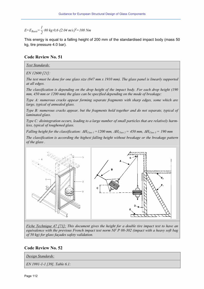
Guidance for European Structural Design of Glass Components
Page 112
E EBasis 1
2 80 kg 0 2.0 m s 2 100 Nm
This energy is equal to a falling height of 200 mm of the standardised impact body (mass 50
kg, tire pressure 4.0 bar).
Code Review No. 51
Test Standards:
EN 12600 [21]:
The test must be done for one glass size (847 mm x 1910 mm). The glass panel is linearly supported
at all edges.
The classification is depending on the drop height of the impact body. For each drop height (190
mm, 450 mm or 1200 mm) the glass can be specified depending on the mode of breakage:
Type A: numerous cracks appear forming separate fragments with sharp edges, some which are
large, typical of annealed glass.
Type B: numerous cracks appear, but the fragments hold together and do not separate, typical of
laminated glass.
Type C: disintegration occurs, leading to a large number of small particles that are relatively harm-
less, typical of toughened glass.
Falling height for the classification: HClass 1 =1200 mm, HClass 2 = 450 mm, HClass 3 = 190 mm
The classification is according the highest falling height without breakage or the breakage pattern
of the glass .
Fiche Technique 47 [71]: This document gives the height for a double tire impact test to have an
equivalence with the previous French impact test norm NF P 08-302 (impact with a heavy soft bag
of 50 kg) for glass façades safety validation.
Code Review No. 52
Design Standards:
EN 1991-1-1 [39], Table 6.1:

Guidance for European Structural Design of Glass Components
Page 113
Categories dependent on the utilisation of the building:
Category A: living space
Category B:office space
Category C: area with gathering
Category D: shopping space
The categories are related to
- vertical live load for floors and balconies and
- horizontal line loads for core walls and barriers.
DIN 18008-4 [44]:
The classification is according to the type of structure. It is not related to the type of utilisation .
Verification ULS for static loading: according to DIN 18008-1
Verification SLS for static loading according to DIN 18008-1
Verification ULS for dynamic loading: verification of the glass and the related connection (linear
support or point fixings), the verification of the dynamic loading is possible according method 1 and
2 explained above. Beyond that, some systems are given (glass type, size and boundary conditions)
which have been proofed by testing (empirical approach).
Falling height for verification by testing: HCat.A = 900 mm, HCat.B = 700 mm, HCat.C = 450 mm
Falling height for verification by calculation: H = 200 mm
M
kmodd
fkR
withM =1,0 and
kmod,thermally toughened glass = 1.4; kmod,heat strengthened glass = 1.7; kmod,float glass = 1.8
Definition of barrier classes and allowed type of glazing:
Edge protection of the glass panels is necessary apart from point supported laminated glass panels
with a sufficient residual resistance after breakage.
Category A
General requirements:
- Laminated glass
- In the case of insulating glass: combination
of laminated glass and monolithic thermal-
ly toughened glass
Category B

Guidance for European Structural Design of Glass Components
Page 114
General requirements:
Laminated glass
Category C
C1 C2 C3
General requirements:
- Laminated glass; apart from panels with linear supported at all edges also mono-
lithic thermally toughened glass is allowed (C1 and C2)
- Insulating glass panes: see insulating glass panels category A
BS 6180 [61]:
There are effectively 4 levels: domestic, commercial, light crowd, heavy crowd.
Loads are line load, concentrated load and uniformly distributed load. (Typically for glass, the
thickness is determined by the concentrated load (smaller panes) and line load (larger panes)).
Any glass types can be used provided appropriate risk analysis has been undertaken and the glass is
a safety glass according to EN 12600.
CSN 74 3305 [65]:
Types of barrier glazing: Recommended types of glass:
A: 4-sided supported glazing (infill panel) with
self-supporting handrail
All kind of laminated safety, monolithic thermal-
ly toughened glass (only if the person is not fall-
ing into the glazing, e.g. sloping balustrades of
stairs) or insulating glass units with at least one
safety laminated glass pane
B: 4-sided supported glazing where the handrail
is supported by the glazing
All kind of laminated safety made of thermally
toughened or heat strengthened glass
C: 4-sided supported glazing with the balustrade
function without handrail
All kind of laminated safety

Guidance for European Structural Design of Glass Components
Page 115
D: 3-sides or 2-sides supported or point sup-
ported glazing
All kind of laminated safety glass, in case of
point-supported glass with drilled holes the
glass must be chemically, heat strengthened or
thermally toughened (Heat-Soak-Test recom-
mended)
E: self-supporting glass balustrade with contin-
uous handrail or without handrail
All kind of laminated safety glass with chemical-
ly, heat strengthened or thermally toughened
glass (with Heat-Soak-Test), the version without
handrail is only allowed inside without public
traffic
General requirements for the supports:
Group A,B,C: Edge cover minimum 12 mm, but at least 1.5
times the thickness of the glass
Group D: Edge cover minimum 18 mm, in case of point
supported glass tests are necessary
Group E: The edge clamping is described in detail. The
detail is in line with the requirements for cate-
gorie B of DIN 18008-4 [44].
ULS: Horizontal loading according to EN 1991-1-1 (line load)
Impact test or given glass types already proved by testing
Cahier CSTB 3034 [69]: This document defines the experimental procedure dedicated to glass can-
tilever balustrades. The experimental campaign is composed of railing tests, impact tests and cyclic
tests (for external balustrades only) and application depends on type of anchoring. Criteria are
based on residual deformation after tests.
Eurocode Outlook No. 31
(1) For the dynamic impact, Eurocode should allow for both a theoretical and an experimental
Guidance for European Structural Design of Glass Components
Page 116
verification to prove the load capacity of the glass under soft impact.
(2) The system, the design scenario, the consequence class and the failure limits have to be
specified. Especially the definition of the impact energy for the respective components and
the impact location should be given.
(3) The notations must be unified to avoid misunderstandings between the basis of design, the
Eurocode and the national documents used so far.
(4) The requirements should or may consider modifications through NADs.
(5) In the scope of this, Eurocode should indicate that also the substructure always has to pro-
vide the same safety against impact as the glass.
6.9 Cold bent glass
Cold bending of glass is a technique suitable for large glazed surfaces with low curvature. A
cold bent glass panel is not a product but rather is a construction method. That’s the reason
why it is classified in this report as a secondary structural element.
The glass is produced flat and then it is bent on site during installation, pushing or pulling an
edge or a corner of it, so to reach the desired deflection and curvature.
Two kinds of curvature can be distinguished:
Bending in a cylindrical shape (single curvature), when opposite edges of glass re-
main parallel and two edges result curved.
Warping in a double curvature shape, when one corner is displaced and edges re-
main straight but no more parallel.
A further possibility of cold bending is the “laminated cold bent glass”, here the glass panels
are bended and laminated with a stiff ionomer interlayer. Apart from a small elastic recovery
after the lamination process the laminate keeps its form. The result of this is a glass product
because the glass producer is directly responsible for the form and the durability related to
the bending. Furthermore, since the market is dominated by only one producer, so the Euro-
code should not deal with this.
Glass is quite flexible, thanks to its low elasticity modulus (around 70 000 MPa), so it is pos-
sible to bend it considerably without breakage. Nevertheless, some special care should be
taken to the following issues:
Cold bending procedure induces a permanent strain, and consequently a permanent
stress, in the glass pane, which should be considered when evaluating its strength
and in combination with external loads. As a matter of fact, it is known that glass
strength is sensitive to load duration.
When dealing with bending laminated glass, consideration should be given to the
stress induced in the interlayer and to the misalignment of the glass plies at their
edges, resulting in an exposition of the interlayer rim, with possible consequences of
edge delamination effects. However, it should also be considered that the creep of
the polymeric interlayer material, subjected to such permanent strain, will end up in a
relaxation of it and in consequent fading of the stress in the interlayer and thus a de-
crease of stress in the glass pane in the whole (because of the loss of shear collabo-
ration between the glass plies). Because of such effect, at least two stages should be
considered in the analysis: first, an installation stage, when the deformation load is

Guidance for European Structural Design of Glass Components
Page 117
applied in a reasonably short time (some minutes) and the laminated glass results to
become more stiff; influence of temperature on the interlayer shear modulus should
also be considered in this stage; second, a long term stage, when the polymeric inter-
layer has already crept and the laminated glass pane results to be less stiff (as far as
this load contribution is concerned).
When cold-bending insulating glass, special attention should be given also to the
stresses induced in the sealing polymer, in the polymeric interlayer and in the spacer.
Exceeding stresses could result in a loss of moisture tightness of the isolating unit.
Whatever the restraining system of glass to its supporting structure (i.e. silicone joint,
rebate cover, point fixing, etc.), such restraint will support a not-negligible load, be-
cause of the cold bending, and therefore its strength and deformation shall be veri-
fied.
Eurocode Outlook No. 32
(1) Since cold bending affects the effective strength of glass, the Eurocode should address cold
bent glass. This applies for both, monolithic and laminated sections. However for laminated
glass the viscous behaviour of the interlayer should be considered with regard to where,
when and how the curvature is introduced.
(2) For laminated glass it should be considered, where, when and how the curvature is intro-
duced.
(3) It should be considered that also stability and stiffness behaviour of cold bent glass is differ-
ent compared to pure flat glazing.
(4) Eurocode should give specifications on how to treat respectively verify the resulting forces on
the substructure.
6.10 Glass in Photovoltaic applications (PV modules)
Glass is the main material for photovoltaic applications. Till now, the standards do not pro-
vide a level of safety here comparable to existing glass standards or design standards. Code
Review No. 53 gives an overview of existing test standards.
In general the application of PV modules can be distinguished between structural (e.g. roof
glazing or facades) or non-structural.
Code Review No. 53
Test standards:
EN IEC 61646 [29] and EN IEC 61215 [30]: The goal of these standards is to determine the elec-
trical and thermal characteristics of the tested modules including a mechanical load test, where one
specimen is subjected to a distributed surface load of 2.4 kN/m² or 5.4 kN/m². In addition these
standards define a hail test and a thermic cycling test to ensure the electric functionality but it do
not consider sufficiently the glass-specific material behaviour, in particular under thermal loads.
EN IEC 61646 does not consider sufficiently the time-dependent behaviour of the strength of an-
nealed float glass and, as the tests are carried out at room temperature, a certain shear transfer
between the upper and the lower glass plate is active due to the lamination sheet. This shear trans-
Guidance for European Structural Design of Glass Components
Page 118
fer often does not exist in the real installation situation under solar radiation with the usual viscoe-
lastic lamination sheets (PVB, EVA).
EN IEC 61730 [31][32]: This standard defines requirements for the construction of PV modules, to
ensure the electrical and mechanical functionality for the designated lifetime. The tests refer to IEC
61646 respectively IEC 61216 and define additionally a pendulum impact test for a proof of safety
of the broken module.
Design Standard: VDE 0126-21 [58]: According to this standard PV modules must meet the re-
quirements of the German glass standards, depending on the application.
Eurocode Outlook No. 33
(1) A proof of the bearing capacity by calculation should be done in the future according to the
Eurocode. Additionally, the load case temperature has to be considered more precisely since
variable temperature profiles over the cross-section or in plane can lead to design relevant
principal tensile stresses.
(2) Mechanical bearing capacity tests should be defined, based on the fundamentals of structural
design, e.g. according to EN 1990 Appendix D. Hence, with a test sequence which includes
the real actions (storage conditions, load type and duration, temperature, etc.) and a suffi-
cient number of specimens, the design value of the resistance can be determined and opposed
to the design value of the impact loads.
(3) The consequence classes should be specified.
(4) Adequately types of glass should be proposed, e.g. if a connection socket is installed on the
surface area of the module, then the drilled rear glass must be considered and should be
thermally toughened.
6.11 Reinforced glass components with enhanced redundancy
An interesting and promising method to enhance the redundancy and residual resistance of
glass components, such as glass panels and glass beams, is the incorporation of reinforce-
ment in the glass component. This reinforcement (e.g. steel, timber, GFRP or CFRP) can be
bonded to the glass by means of adhesives or by means of PVB and ionomer interlayers.
Upon glass failure the reinforcement bridges the crack(s) in the glass and carries the tensile
force. This allows the component to still carry significant load even if the glass is (extensive-
ly) fractured. Various reinforcement solutions and bonding techniques are currently under
development in a scientific context, e.g. [186][189][190][236] [241][243], and some solutions
have already found practical application in realized projects, e.g.[191][205]. Points of continu-
ing investigation are particularly the performance of the adhesive bond between glass and
reinforcement, and the overall structural performance of the reinforced glass component un-
der various environmental and loading conditions (see chapters 7 and 8.4).
Reinforced glass components are very promising due to their significant robustness and re-
dundancy. Although the general proof of concept is already extensively provided, further re-
search may focus in detail on the structural performance of these reinforced glass compo-
nents under various loading conditions. Furthermore, additional research into the perfor-
mance of the adhesive bond between the glass and the reinforcement is needed.
Guidance for European Structural Design of Glass Components
Page 119
7 Design of primary structural components
7.1 General
Like previously explained glass can be used as primary structural components which are a
part in the overall structural system. For these situations the glass elements have to be de-
signed with higher requirements on robustness and redundancy, see chapter 0. Also special
considerations have to be taken whether fire action is a relevant issue and if so, which pro-
tection measures (additional fire glass) or redundancy design (safeguard protection etc.)
should be performed.
Further references to the stability of glass components can be found in (e.g. [210]).
Eurocode Outlook No. 34
(1) For the design of primary structural elements and for each design case, the Eurocode
should provide rules for
Cross-sectional layer composition of laminates to achieve robustness and redundancy
against failure of one or more glass-layers (on the level of the cross section),
Background safety measures in the component itself in case of failure of a glass pane
(on the component level),
Additional components that can take over the load bearing in case of failure of a com-
plete component (on the structural building level).
(2) The post-failure-measures should be designed under a reduced safety factor-regime both
for static loading only as well as for the dynamic impact eventually combined with other
occurring actions.
(3) For the cross-sectional laminate design it should be distinguished between “protection lay-
ers” and “load carrying (core) layers”. The load carrying (core) layer itself can consist of
laminates again, the breakage pattern and strength of which should be a major design is-
sue.
(4) To ensure the full protection against hard impact the free edges have to be protected so that
the load carrying core layers are not likely to be destroyed from the edges.
(5) Considerations should be taken on how strong and intensive the impact energy is such that
the thickness and quality of the protection layers as well as the kind of edge protection can
be chosen. Basically the same applies for the choice of interlayer and its thickness.
(6) On the component level sufficient safeguard protection can be achieved by additional glass
panes that take over the structural loads in case of failure of an entire glass panel. These
additional structural systems may be activated only once the glass panel has (totally) failed.
(7) Analogously similar safeguard protection should be considered on the structural building
level.
(8) To some e tend on each of the levels an “overdesign” of the cross-section, the component
or the whole structural ensemble can fulfil the robustness-requirements, too.
(9) In any case, the necessity of the different measures and its combinations should be deter-
mined in advance by both a global and a local failure probability analysis for the relevant
scenarios. Therefore the requirements for “yielding” from specific consequence classes
have to be considered. Alternatively a deterministic approach can be allowed in those cases

Guidance for European Structural Design of Glass Components
Page 120
where sufficient knowledge and experience from prior application and/or research work is
available.
7.2 Shear panels
7.2.1 Buckling of shear panels with single point load introduction at the corners
along the diagonal (corner loaded shear panels)
If shear panels are added to lattice girders with missing diagonals (such as „Vierendeel-
systems“) filling the rectangular openings, these “glass fillings” can take over the diagonal
propping forces. By that very transparent steel-glass truss works can be obtained, Figure
7-1.
Figure 7-1 Steel-glass lattice (“ladder”) girder with glass-shear panels replacing the diagonals
Thereby the shear panel is loaded under an inner compression force acting along its diago-
nal. Thus it can be regarded as a compression beam with variable flexural inertia continuous-
ly supported along its axis. The continuous support is enabled by the “other” diagonal per-
pendicular to the considered diagonal in compression, Figure 7-3. Thus, the glass panel has
to be supported at all four corners.
As the glass fillings are loaded by a distinct linear in-plane compression force they are to be
assessed against flexural buckling. It should be noted that if the support at the edges would
be continuous instead of punctual at the corners, the flexural buckling phenomenon would
change over to a shear plate buckling problem.
In [150] corner loaded shear panels have been investigated with different detailing of the
glass corners and load introduction. By calculating the elastic critical load of panels with
e.g. square geometries by means of the FEM the related slenderness
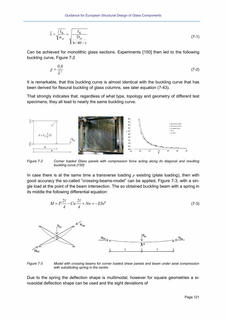
Guidance for European Structural Design of Glass Components
Page 121
t40/b
D
ff
cr
K
cr
K
(7-1)
Can be achieved for monolithic glass sections. Experiments [150] then led to the following
buckling curve, Figure 7-2
2
8,0
(7-2)
It is remarkable, that this buckling curve is almost identical with the buckling curve that has
been derived for flexural buckling of glass columns, see later equation (7-43).
That strongly indicates that, regardless of what type, topology and geometry of different test
specimens, they all lead to nearly the same buckling curve.
Figure 7-2 Corner loaded Glass panels with compression force acting along its diagonal and resulting buckling curve [150]
In case there is at the same time a transverse loading p existing (plate loading), then with
good accuracy the so-called “crossing-beams-model” can be applied, Figure 7-3, with a sin-
gle load at the point of the beam intersection. The so obtained buckling beam with a spring in
its middle the following differential equation:
wEINw4
2Cw
4
2PM
(7-3)
Figure 7-3 Model with crossing beams for corner loaded shear panels and beam under axial compression with substituting spring in the centre
Due to the spring the deflection shape is multimodal; however for square geometries a si-
nusoidal deflection shape can be used and the sight deviations of
a
b 2
F
FF
FDruckdiagonale
Druckdiagonale
Zyl
Zyl=
a
b
√
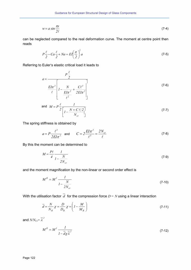
Guidance for European Structural Design of Glass Components
Page 122
2
xsinaw
(7-4)
can be neglected compared to the real deformation curve. The moment at centre point then
reads
a2
EINa2
Ca2
P
2
(7-5)
Referring to Euler‘s elastic critical load it leads to
2
3
2
2
2
EI2
C
EI
N1
EI
2P
a
(7-6)
and
crN
2CN1
1
2PM
(7-7)
The spring stiffness is obtained by
2
3
EI2Pa
and
cr
3
2 N2EI2C
(7-8)
By this the moment can be determined to
crN2
N1
1
4
PM
(7-9)
and the moment magnification by the non-linear or second order effect is
cr
III
N2
N1
1MM
(7-10)
With the utilisation factor d for the compression force D = N using a linear interaction
RRR M
M1
D
D
N
Nd
(7-11)
and N/NCr=2
2
III
d1
1MM
(7-12)

Guidance for European Structural Design of Glass Components
Page 123
is obtained, that means with 2
8,0 the available moment related to the pure moment
capacity reads as follows
d4,01d1M
M
R
I
(7-13)
or generally with the utilisation factors p = p/pR and d :
d4,01d1p
(7-14)
The interaction curve pd is depicted in Figure 7-4.
RD/Dd
Rp/pp
Figure 7-4 Interaction curve, normalised for corner loaded square panels under diagonal compression load
RD/Dd with transverse plate loading Rp/pp [150]
Eurocode Outlook No. 35
(1) The shear buckling verification of shear panels (regardless of what type of load introduc-
tion) can be performed either by a non-linear numerical investigation or by using appropri-
ate buckling curves. The Eurocode on Structural Glass should allow for both methodolo-
gies.
(2) The imperfection assumption of the buckling curves should coincide with the imperfections
that are used for alternative non-linear numerical analysis.
(3) The imperfections for panels of glass in shear are due to two reasons:
a. The geometrical and inherent structural imperfections that can be measured by ex-
periments via Southwell-procedure.
b. The tolerances from erecting and assembling the plate into the frame. Due to the
slenderness of glass panels erecting tolerances may appear. Whereas in the exper-
iments those tolerance are often avoided, in practise they should be assumed addi-
tionally to be a constant value of 3.0 mm.
(4) Reliable interlayer shear stiffness values in dependence on time and temperature can be
taken into account.
(5) The non-linear effect of different load durations on the buckling strength should be taken

Guidance for European Structural Design of Glass Components
Page 124
into account unless the laminate is calculated without any composite effect.
(6) The non-linear interaction of shear loads with transverse loading (wind, snow, gravity,
climatic loading in case of insulating glass …) has to be considered.
(7) The Eurocode should give best practise examples for the detailing of the load introduction
points.
7.2.2 Buckling of continuously supported shear panels
Shear stresses in glass shear panels can be introduced also continuously along the edges,
additionally to those from load introductions in the corners. Mostly the edges are realized by
adhesive bonding techniques (or clamping). It is clear that the continuous edge support in-
creases the buckling resistance. To take this into account a thorough buckling investigation
by FEM or other means is necessary.
Code Review No. 54
Technical recommendation:
CNR-DT-210 [55]: A buckling verification approach for monolithic and laminated glass panels
continuously supported and subjected to in-plane shear loads has been proposed in the Italian
CNR-DT-210 document.
For monolithic panels, the stability check can be performed by comparing the design shear load VEd
with the shear buckling strength Vb,Rd, where Vb,Rd, in accordance with buckling approaches com-
monly used for structural panels composed of traditional construction elements, is defined as Vb,Rd
= A d.
Based on contributions available in literature, the characteristic shear strength k is assumed equal
to the characteristic tensile strength k. At the same time, the buckling coefficient is calculated as
suggested in EC3 for steel structures:
11
22
,
with
]λ)αλα([1 5.02
0 ,
λ the normalized slenderness ratio, and 0 appropriate imperfection factors.
An initial geometrical imperfection proportional to the first modal shape of the panel, of maximum
amplitude w0= L/1000 is taken into account. Based on experimental results and contributions avail-
able in literature, buckling occurs when reaching a maximum tensile strength equal to k/ 1.4 or
equivalently at the attainment of a maximum transversal displacement wmax= L/300. Both these as-
pects are taken into account in the estimation of for monolithic panels composed of various glass
types, by means of imperfection factors = 0.49 and 0 = 0.50 calibrated by numerical and exper-
imental predictions.
The same verification approach (with = 0.49 and 0 = 0.50) is proposed, also for the stability
check of panels composed of laminated glass. In this case, an equivalent thickness formulation de-
rived from Wolfel-Bennison simplified approach is used.
The same verification approach is suggested, both for monolithic or laminated glass, also for panels
not continuously supported along the four edges. In this case, appropriate buckling coefficients k
are proposed for various boundary conditions.
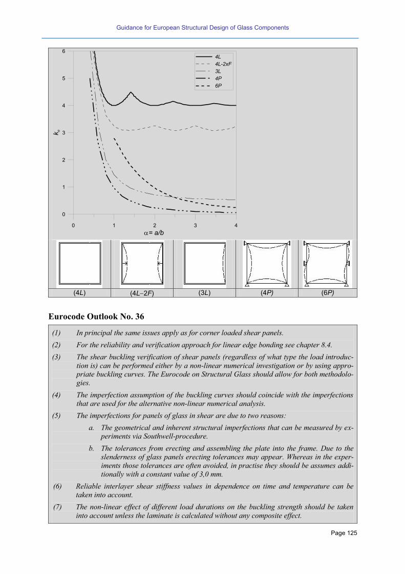
Guidance for European Structural Design of Glass Components
Page 125
(4L) (4L2F) (3L) (4P) (6P)
Eurocode Outlook No. 36
(1) In principal the same issues apply as for corner loaded shear panels.
(2) For the reliability and verification approach for linear edge bonding see chapter 8.4.
(3) The shear buckling verification of shear panels (regardless of what type the load introduc-
tion is) can be performed either by a non-linear numerical investigation or by using appro-
priate buckling curves. The Eurocode on Structural Glass should allow for both methodolo-
gies.
(4) The imperfection assumption of the buckling curves should coincide with the imperfections
that are used for the alternative non-linear numerical analysis.
(5) The imperfections for panels of glass in shear are due to two reasons:
a. The geometrical and inherent structural imperfections that can be measured by ex-
periments via Southwell-procedure.
b. The tolerances from erecting and assembling the plate into the frame. Due to the
slenderness of glass panels erecting tolerances may appear. Whereas in the exper-
iments those tolerances are often avoided, in practise they should be assumes addi-
tionally with a constant value of 3,0 mm.
(6) Reliable interlayer shear stiffness values in dependence on time and temperature can be
taken into account.
(7) The non-linear effect of different load durations on the buckling strength should be taken
into account unless the laminate is calculated without any composite effect.
0 1 2 3 4
= a/b
0
1
2
3
4
5
6k
4L
4L-2xF
3L
4P
6P

Guidance for European Structural Design of Glass Components
Page 126
(8) The non-linear interaction of shear loads with transverse loading (e.g. wind, snow, gravity,
climatic loading in case of insulating glass panels) has to be considered.
7.2.3 Influence of the connection stiffness
Glass panes are increasingly being used to the stabilization of one storey buildings by acting
as shear walls and thus replacing conventional bracings. This is the case for glass pavilions
and some timber or steel frames or facades. The behaviour of such structural systems main-
ly depends on the stiffness of the connections.
The use of mechanical models to predict the behaviour of joints has a long tradition in the
fields of steel and composite structures. The component method proposed in Eurocodes 3
[40] and 4 [42] is based on the association of springs that model the different components of
a joint. Recent research results [209] demonstrate that these models are applicable for the
purpose of the non-cracking pre-design of panes acting as a shear wall, because they are
able to predict the in-plane stiffness and the force necessary to obtain a certain horizontal in-
plane displacement at the top.
Type 1 Type 2 Type 3
Figure 7-5 Adhesive bonded glass panes [209]
Figure 7-6 Mechanical model for circumferentially adhesive bonded glass panes and for glass panes with point support fixings [209]
7.3 Beams with bending about the strong axis – Lateral torsional buck-
ling
7.3.1 Monolithic sections
A beam which is bent about the axes of greatest flexural rigidity may buckle laterally at a
certain critical value of the load. This lateral buckling is of importance in the design of beams
without lateral support, provided the flexural rigidity of the beam in the plane of bending is
large in comparison to the lateral bending rigidity i.e. of the weak axis. As long as the load on
such a beam is below the critical value, the beam will be stable. As the load is increased,

Guidance for European Structural Design of Glass Components
Page 127
however, a condition is reached at which slightly deflected (and twisted) from of equilibrium
becomes possible. The plane configuration of the beam is now unstable, and the lowest load
at which this critical condition occurs represents the critical load for the beam, a phenomenon
which is called lateral torsional buckling.
For beams in bending of monolithic glass, to obtain this failure mode, the cross-section must
be rather slender a narrow rectangle; thickness (width) t and depth (height) h. The elastic
critical moment is given in Figure 7-1 for different loading situations (without further analytical
derivation that may be based on either equilibrium or energy approach). The constants
and are given in Table 7-4.
Section Load cases
Figure 7-7 Loading situations
Table 7-1 Formula for
Type of load Critical moment
.cteM y tzcr IGIEM
.cteqz
zP at midspan
2
z
t
2
Mp
1
2Mp
1
2ki
1
crIE
IGz
c
c
2
1z
c
c
2
1N
c
1M
By a non-linear analysis basically the non-linear behaviour such as flexural buckling can be
found. That was verified by experiments also for glass beams. Thereby for monolithic sec-
tions an effective imperfection of e0 00 [136] was found.
As always this allows now two options for the verification
The non-linear analysis by a second order calculation using e0.
The use of buckling curve that are derived in advance with e0.
However a second order analysis seems often too laborious for ordinary cases, then the use
of buckling curves is quicker. By
el
crLT
M
M with crt
2
el M,fb
htM
see Table 7-1. (7-15)
the verification format becomes

Guidance for European Structural Design of Glass Components
Page 128
0,1
M
M
d,elLT
Ed
(7-16)
It is interesting to note, that the onset 0 can be discussed similar as for flexural buckling.
The limiting value is here also the tension strength at the edge.
Several research projects analysed the behaviour of monolithic glass beams and developed
buckling curves [135][136][137][225].
7.3.2 Lateral torsional buckling of glass beams with laminated cross sections
For the assessment of lateral torsional buckling (LTB) of glass beams with monolithic sec-
tions the elastic theory can applied directly (see the preceding chapter) as long as the imper-
fections for initial lateral deflection coupled with the initial twist v0 and 0 are known, as well
as the stress limits Rd (depending on time and load- combination). However, when LTB-
problems with beams of laminated glass the sandwich effect needs consideration together
with the non-linear, temperature- and time-dependant behaviour of the interlayer.
As a first approach and on the safe side, the composite action of the interlayer may be ne-
glected and the beam can be treated as the sum of single beams with monolithic sections of
the single glass layers, i.e. only the additive effect is considered. However mostly this would
lead to old fashioned and heavy solutions critical load cases inducing LTB-problems often
only appear over a short time period and therefore despite of relaxation effects the interlayer
do provide sufficient shear stiffness to increase the LTB- resistance. So it is for economy
reasons to consider composite action with regard to LTB.
In the following, the approach and the most important steps for a recently developed calcula-
tion and design concept [166] is presented by which the lateral torsional buckling behaviour
of laminated glass beams can be verified. The concept takes into account the time- and tem-
perature- dependant stiffness of the interlayer and further it considers the lamination influ-
ence by means of an extended warping approach. The concept is generally valid as long as
the deformations are small and the material parameters are known, i.e. it does not depend
on a specific type of interlayer or glass. It has been verified by finite element simulations as
well as by experimental results, which is going to be shown.
The lateral and torsional deflections of simply supported glass beams that are loaded accord-
ing to Figure 7-7 and have initial imperfections v0 respectively 0 according to Figure 7-8 can
be described by basic non-linear equations [166] [167] given in Table 7-2 and Table 7-3 us-
ing the coefficients according to Table 7-4.

Guidance for European Structural Design of Glass Components
Page 129
Figure 7-8 LTB of laminated glass beams: denominations and imperfection approach
Table 7-2 Lateral deformations
.cteM y
xsin
IE
MIG
vIE
MM
IE
IG
)x(v
z
2y
2
t
0z
2y
0yz
t
II.Th
.cteqz
xsin
zMcIE
McIG
vIE
McM
IE
IGc
)x(v2
py2z
2y
21
2
t
0z
2y2
10yz
t1
II.Th
zP at midspan
Table 7-3 Torsional deformations
Type of load non-linear rotation
.cteM y
xsin
IE
MIG
vMIE
M
)x(
z
2y
2
t
0y
2
0z
2y
II.Th
.cteqz
xsin
zMcIE
McIG
vMczMcIE
Mc
)x(2
py2z
2y
21
2
t
0y
2
1py
2
2z
2y
21
0
II.Th
zP at midspan
Table 7-4 Coefficients c1 and c2
1c 2c
.cteqz 8693,02
3
22
8106,0
82
zP at midspan 7026,02
122
8106,08
2

Guidance for European Structural Design of Glass Components
Page 130
Thereby the torsional stiffness G IT and the bending stiffness about the weak axis E IZ are
highly influenced by the shear stiffness of the interlayer GF the amount of which can be de-
termined by evaluation of relaxation tests, for example at -10°C, 0°C or room temperature
23°C. For this purpose a good evaluation procedure has been found using the “torsional
test”, see chapter 2.2.4. By that it has been found for PVB interlayers, that a lower bound for
the short term shear stiffness (up to 1h load duration) can be assumed to GF = 0.2 N/mm2 at
higher temperatures > 20°C. For long term loading (more than 1h load duration) the shear
modulus of PVB interlayers converges to zero at higher temperatures > 20°C [166].
However as this is true only for PVB, for stiffer interlayer material such as Ionomer sheets
there might be also a value different from zero also for a long term time period.
The equations for calculating the critical bending moments about the strong axis, which also
strongly depend on the shear stiffness of the interlayer, have been given in Table 7-1. The
influence of the shear modulus GF on stiffness and stress can be determined according to the
“Extended bending and torsion theory” [166]. As shown in Figure 7-9 for bending and in Fig-
ure 7-10 for torsion, it considers the displacements in the shear gap by further degrees of
(“step-like”) warping deformations and additional to the rigid body warping defor-
mations N due to normal forces, B due to bending and T due to torsion.
Figure 7-9 Rigid body warping and additional step-like warping deformations and for bending
Figure 7-10 Rigid body warping zT and
xT and additional warping deformation for torsion
By solving the differential equations of the extended bending and torsion theory we obtain
the equivalent geometric stiffness is obtained
= 1N = - yB 1
2
1
1
1 112
x
y
xy
= 1 = - y N B 1
21
= yz
T T = y zx x
1
x z
y
z= yT
x
1 2
x
y
x z
= y zxT
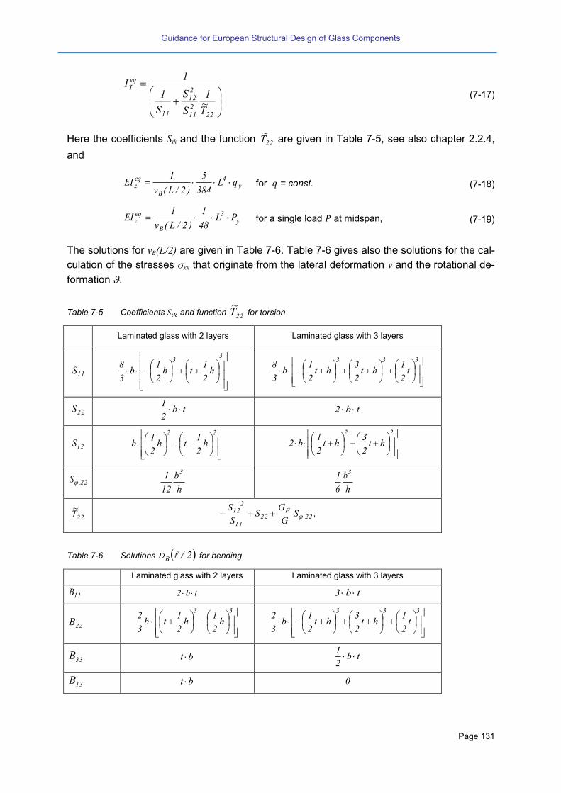
Guidance for European Structural Design of Glass Components
Page 131
22211
212
11
eqT
T~1
S
S
S
1
1I
(7-17)
Here the coefficients Sik and the function 22T~
are given in Table 7-5, see also chapter 2.2.4,
and
y4
B
eqz qL
384
5
)2/L(v
1EI for = const. (7-18)
y3
B
eqz PL
48
1
)2/L(v
1EI for a single load at midspan, (7-19)
The solutions for vB(L/2) are given in Table 7-6. Table 7-6 gives also the solutions for the cal-
culation of the stresses xx that originate from the lateral deformation v and the rotational de-
formation .
Table 7-5 Coefficients and function 22T~
for torsion
Laminated glass with 2 layers Laminated glass with 3 layers
11S
33
h2
1th
2
1b
3
8
333
t2
1ht
2
3ht
2
1b
3
8
22S tb2
1 tb2
12S
22
h2
1th
2
1b
22
ht2
3ht
2
1b2
22,S
h
b
12
1 3
h
b
6
1 3
22T~
22,F
2211
212 S
G
GS
S
S ,
Table 7-6 Solutions 2/B for bending
Laminated glass with 2 layers Laminated glass with 3 layers
11B tb2 tb3
22B
33
h2
1h
2
1tb
3
2
333
t2
1ht
2
3ht
2
1b
3
2
33B bt tb2
1
13B bt 0

Guidance for European Structural Design of Glass Components
Page 132
Laminated glass with 2 layers Laminated glass with 3 layers
23B thtb2
1 2
22
ht2
1ht
2
3b
2
1
33B~
3322
223
11
213 B
B
B
B
B 33
22
223 B
B
B
33,S h
b
h2
b
)2/(v~B
22
4y
BE384
q5
22
3y
BE48
P
(P at midspan)
3 33
233,F
B~
E
S~
G
3,M
2cosh
11
8
33
3
32
1tanh2
(P at midspan)
3,V 3,M333
22 15
48
B~B
3,M333
22 112
B~B~
(P at midspan)
)2/(v~ 1 )2/(v~
B
BB3,V
22
32
)2/(vB 122
32B v~
B
Bv~
)2/(MB
~
8
q 2y
(q = const.) 4
Py (P at midspan)
1~
122
32
11
31 yB
B
B
B with
htyh
hy)ht(
für
für
0
1
21
21
21
21
1
122
23 yB
B with
htyht
tyt
)ht(yht
für
für
für
2/1
0
2/1
23
21
21
21
21
23
1
xx
1
33
3,M3
22
B~
~
B~
r~
B
~M
B
In order to verify the calculative assumptions pilot tests have been performed at simply sup-
ported beams out of monolithic and laminated glass. Thereby the hydraulic jack was laterally
fixed so that this was also the horizontal boundary condition for the test specimen. The tor-
sional rotations of the ends of the beams have been prevented (fork support) whereas the
end supports were allowed to move laterally, see Figure 7-11. The load has been applied
deformation controlled using different linear displacement-time-ramps to check the influence
of the loading and unloading speed.

Guidance for European Structural Design of Glass Components
Page 133
Figure 7-11 LTB- tests at beams of glass [166]
Figure 7-12 shows the load-time curves and displacement–time curves for a testing rate of vB
= 0.5 mm/s, once for a linear displacement-time-ramp up to Pu (ULS test), and once as a hold-
ing test with a vertical jack displacement up to approximately 0.9 x Pu. The ultimate load here
is proportional to Pki = f (GF(23°C, t)).
Note: In case of load controlled testing (here not applied) no decreasing can occur and fur-
ther, the beams will fail always due to sudden material breakage.
Figure 7-12 Test results with displacement-time-ramps and holding tests ( B = 0.50 mm/s) [166]
0
5
10
15
20
25
0 200 400 600 800 1000 1200
Fo
rce
F [
kN
]
Time [sec]
Pki,FE [G(t,23 C)upper bound]
Pki,FE [G(t,23 C)lower bound]
Load bearing testsL = 2000 mmb = 360 mmt = 2 x 8 mm TTGF at midspanvB = 0.50 mm/sec
Holding test
0
2
4
6
8
10
12
0 200 400 600 800 1000 1200Ve
rtic
al d
isp
lac
em
en
t w
[m
m]
Time [sec]
Holding test
Load bearing test
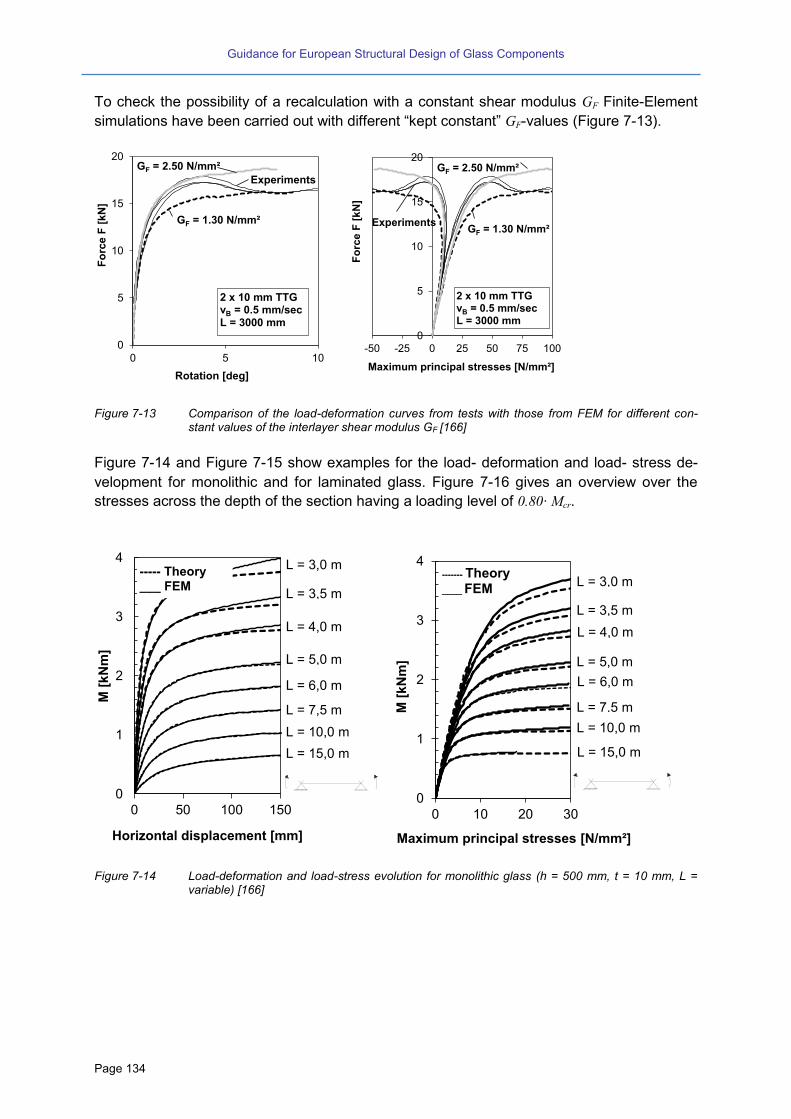
Guidance for European Structural Design of Glass Components
Page 134
To check the possibility of a recalculation with a constant shear modulus GF Finite-Element
simulations have been carried out with different “kept constant” GF-values (Figure 7-13).
Figure 7-13 Comparison of the load-deformation curves from tests with those from FEM for different con-stant values of the interlayer shear modulus GF [166]
Figure 7-14 and Figure 7-15 show examples for the load- deformation and load- stress de-
velopment for monolithic and for laminated glass. Figure 7-16 gives an overview over the
stresses across the depth of the section having a loading level of 0.80 Mcr.
Figure 7-14 Load-deformation and load-stress evolution for monolithic glass (h = 500 mm, t = 10 mm, L = variable) [166]
0
5
10
15
20
0 5 10
Fo
rce F
[kN
]
Rotation [deg]
2 x 10 mm TTGvB = 0.5 mm/secL = 3000 mm
GF = 2.50 N/mm²
GF = 1.30 N/mm²
Experiments
0
5
10
15
20
-50 -25 0 25 50 75 100F
orc
e F
[k
N]
Maximum principal stresses [N/mm²]
GF = 1.30 N/mm²
GF = 2.50 N/mm²
Experiments
2 x 10 mm TTGvB = 0.5 mm/secL = 3000 mm
0
1
2
3
4
0 50 100 150
M [
kN
m]
Horizontal displacement [mm]
----- Theory ___ FEM
L = 15,0 m
L = 10,0 m
L = 7,5 m
L = 5,0 m
L = 6,0 m
L = 4,0 m
L = 3,5 m
L = 3,0 m
0
1
2
3
4
0 10 20 30
M [
kN
m]
Maximum principal stresses [N/mm²]
L = 15,0 m
L = 10,0 m
L = 7,5 m
L = 5,0 m
L = 6,0 m
L = 4,0 m
L = 3,5 m
L = 3,0 m------- Theory ____ FEM
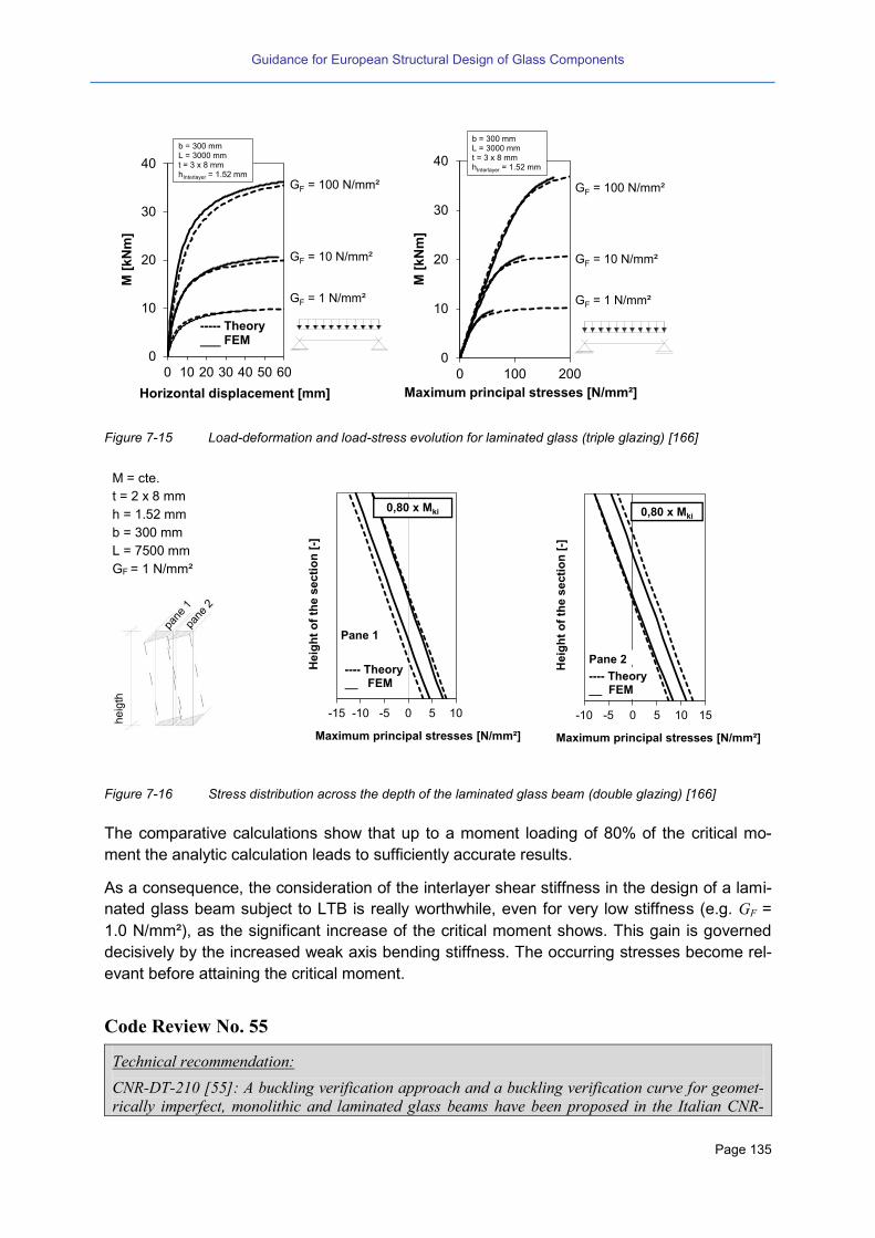
Guidance for European Structural Design of Glass Components
Page 135
Figure 7-15 Load-deformation and load-stress evolution for laminated glass (triple glazing) [166]
M = cte.
t = 2 x 8 mm
h = 1.52 mm
b = 300 mm
L = 7500 mm
GF = 1 N/mm²
Figure 7-16 Stress distribution across the depth of the laminated glass beam (double glazing) [166]
The comparative calculations show that up to a moment loading of 80% of the critical mo-
ment the analytic calculation leads to sufficiently accurate results.
As a consequence, the consideration of the interlayer shear stiffness in the design of a lami-
nated glass beam subject to LTB is really worthwhile, even for very low stiffness (e.g. GF =
1.0 N/mm²), as the significant increase of the critical moment shows. This gain is governed
decisively by the increased weak axis bending stiffness. The occurring stresses become rel-
evant before attaining the critical moment.
Code Review No. 55
Technical recommendation:
CNR-DT-210 [55]: A buckling verification approach and a buckling verification curve for geomet-
rically imperfect, monolithic and laminated glass beams have been proposed in the Italian CNR-
0
10
20
30
40
0 10 20 30 40 50 60
M [
kN
m]
Horizontal displacement [mm]
----- Theory ___ FEM
GF = 10 N/mm²
GF = 1 N/mm²
GF = 100 N/mm²
b = 300 mmL = 3000 mmt = 3 x 8 mmhInterlayer = 1.52 mm
0
10
20
30
40
0 100 200
M [
kN
m]
Maximum principal stresses [N/mm²]
------- Theorie
G =
G =
G = 1
GF = 10 N/mm²
GF = 1 N/mm²
GF = 100 N/mm²
b = 300 mmL = 3000 mmt = 3 x 8 mmhInterlayer = 1.52 mm
-15 -10 -5 0 5 10
Heig
ht
of
the s
ecti
on
[-]
Maximum principal stresses [N/mm²]
0,80 x Mki
---- Theory__ FEM
Pane 1
-10 -5 0 5 10 15
He
igh
t o
f th
e s
ecti
on
[-]
Maximum principal stresses [N/mm²]
0,80 x Mki
---- Theory__ FEM
Pane 2

Guidance for European Structural Design of Glass Components
Page 136
DT-210 document.
A buckling verification curve is proposed for the stability check of glass beams in out-of-plane
bending. Also in this case, the proposed buckling curve is defined like in EC3 for steel structures.
The imperfection factors 0.2 and 0 =0.20 are calibrated by experimental and numerical re-
sults available in literature for monolithic or laminated glass beams of various glass types, subject-
ed to constant bending moments, distributed lateral loads or concentrated forces at mid-span, and
with initial imperfections of different size. For laminated glass beams, the same stability check can
be performed by means of the Wolfel-Bennison equivalent thickness approach.
AS 1288 [66]: The Australian Design Standard for Glass gives a recommendation in the form not to
exceed the critical bending moment divided by the factor 2.0. Basic formulas for the calculation of
Mcrit are given.
Eurocode Outlook No. 37
(1) As for buckling columns or for shear panels the LTB-verification of beams can be per-
formed either by a full non-linear numerical investigation or by using appropriate buckling
curves. The Eurocode on Structural Glass should allow for both methodologies.
(2) The imperfection assumption of the buckling curves should coincide with the imperfections
that are used for the numerical non-linear analysis.
(3) Reliable values for interlayer shear stiffness in dependence on time and temperature can be
taken into account.
(4) The non-linear effect of different load durations on the buckling strength should be taken
into account unless the laminate is calculated without any composite effect.
(5) The boundary conditions at the supports and the position of load introduction has to be
considered in particular. The Eurocode should give best practise examples for the detailing
of the load introduction and bearing supports.
7.4 Columns
7.4.1 General
Also for columns laminated sections are necessary in order to achieve sufficient robustness
against impact as well as to achieve redundancy. The design of such load bearing glass
structures necessitates the knowledge about the stability behaviour of laminated glass panes
and appropriate technical rules. However, the load bearing capacity of monolithic glass col-
umns must be analysed and thus known first.
Several research projects in Europe were dealing with the load bearing capacity of glass
columns. For pane-like glass columns made of heat strengthened and thermally toughened
glass design rules under axial loading have been derived. These rules have been verified by
existing buckling tests, new experimental tests and numerical simulations.
The proposed design rules are verified by existing buckling tests ([86] [225] [226] [227] [228])
and by experimental tests and numerical simulations [229].
Code Review No. 56
Technical recommendation:
CNR-DT-210 [55]: A buckling curve has been proposed for monolithic and laminated glass col-
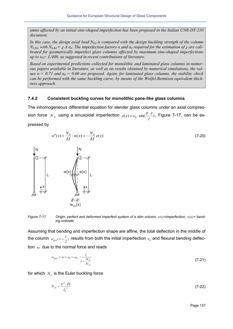
Guidance for European Structural Design of Glass Components
Page 137
umns affected by an initial sine-shaped imperfection has been proposed in the Italian CNR-DT-210
document.
In this case, the design axial load NEd is compared with the design buckling strength of the column
Nb,Rd, with Nb,Rd = χ A σd. The imperfection factors and 0 required for the estimation of χ are cali-
brated for geometrically imperfect glass columns affected by maximum sine-shaped imperfections
up to w0= L/400, as suggested in recent contributions of literature.
Based on experimental predictions collected for monolithic and laminated glass columns in numer-
ous papers available in literature, as well as on results obtained by numerical simulations, the val-
ues = 0.71 and 0 = 0.60 are proposed. Again, for laminated glass columns, the stability check
can be performed with the same buckling curve, by means of the Wolfel-Bennison equivalent thick-
ness approach.
7.4.2 Consistent buckling curves for monolithic pane-like glass columns
The inhomogeneous differential equation for slender glass columns under an axial compres-
sion force EN using a sinusoidal imperfection )sin()( 0
l
xexe
, Figure 7-17, can be ex-
pressed by
)()()( xeEI
Nxw
EI
Nxw EE (7-20)
Figure 7-17 Origin, perfect and deformed imperfect system of a slim column, e( )=imperfection, w( )= bend-ing ordinate
Assuming that bending and imperfection shape are affine, the total deflection in the middle of
the column )2
lx(wges results from both the initial imperfection
0e and flexural bending deflec-
tion w due to the normal force and reads
cr
E00ges
N
N1
1eeww
(7-21)
for which crN is the Euler buckling force
2k
2
crl
EIN
(7-22)

Guidance for European Structural Design of Glass Components
Page 138
The stress equation according to 2nd order theory using the magnification factor
cr
E
N
N1
1
(7-23)
reads as follows:
cr
E
0EE
N
N1
1
W
eN
A
N
(7-24)
If the values of the imperfection 0e and the permissible stress
uf are known, the buckling
stability can be assessed by equation (7-26) and (7-27) in the form of a stress verification.
However, as the magnitude of the compressive strength of glass differs from that of the ten-
sile strength, the verification of buckling resistance must fulfil both a compression and a ten-
sion check:
t,u
cr
E
0EEt f
N
N1
1
W
eN
A
N
and
TTGfor²mm
N120
HSGfor²mm
N70
f t,u
(7-25)
c,u
cr
E
0EEc f
N
N1
1
W
eN
A
N
and e.g.²mm
N500f c,u
(7-26)
In view of a consistent verification format, which avoids the double check for both the com-
pression and tensile case, buckling curves are to be proposed for monolithic pane-like glass
columns, which are independent of the glass strength but are able to separate the range of
the compressive strength from that of the tensile strength. The background for this purpose
are buckling curves in the intended established European format
tu
tut
fA
N
,
)(
(7-27)
which depends on the non-dimensional slenderness
cr
tu
tN
fA ,
(7-28)
Reference value of the strength shall be the standardized tensile strengthtuf ,
(index “ ” attuf ,,
t andt ). The stress equation (7-26) then reads using the variables
t andt :
2ttt
2t
2tt 10 (7-29)
and W
Ae 0 (7-30)
Implementing a parameter )(e t0 considering the effect of the geometric imperfection of the
glass member
A
We tt )(0
(7-31)
equation (7-30) can be written in the Ayrton-Perry-format:

Guidance for European Structural Design of Glass Components
Page 139
t2ttt )1()1( (7-32)
The solution of equation (7-33) is the function of the buckling curves )( tt for that range of
slenderness, in which tensile failure is decisive
2t
2tt
t
1
(7-33)
with
)1(2
1 2ttt (7-34)
Analogously, but with different sign, equation (7-27) describes that range of slenderness, in
which the compression failure is decisive
22
tfcc
f
c
n
n
(7-35)
with
TTGfor17,4HSGfor14,7
f
fn
t,u
c,uf
; t,u
tuc
fA
)(N
(7-36)
and )n1(2
1 2tftc (7-37)
The variable results from the equation (7-32) and can be written as:
t,u
0
t
0
f
E3
l
e
W
Ae
(7-38)
Using an effective imperfection value e.g. 400/Le0 (this effective imperfection was verified
in [225][227][229] for buckling test with centric normal force), so 430.0HSG and 329.0TTG
yield from equation (7-38).
As a result Figure 7-18 shows the so derived buckling curves with non-dimensional slender-
ness relating to tensile strength for heat strengthened and toughened safety glass. Thereby
the range, in which the failure due to reaching the compressive strength or due to reaching
the tensile strength is decisive, is visible.
The intersection point of the buckling curves )( tt with 0.1t can be considered as a hori-
zontal curve shift like the European buckling curves for steel columns [230] incorporate. For
attaining a formal compatibility with the European buckling curves the buckling curves for
glass columns can be written:
2t
2**
*t
1
with
TTGfor)(92.0
HSGfor)(89.0
0,t
0,tt
(7-39)
and ))(1(2
1 2t0,tt (7-40)
and 0,1*t with
TTGfor)(92.0
HSGfor)(89.0
0,t
0,tt
(7-41)

Guidance for European Structural Design of Glass Components
Page 140
Equation (7-40): ),( 0,
*
ttt f and equation (7-41): ),( 0,ttf are not identical with the
equation (7-34): )( tt f or the equation (7-35): )( tt f respectively. Two buckling curves
depending on the respective glass strength are remaining. Therefore, in order to avoid differ-
ent buckling curves for heat strengthened and toughened safety glass the value for has to
be equalized. For this purposes the -value for heat strengthened glass should be selected
also for the toughened safety glass: 430.0new,TTGHSG . In this case the effective imperfec-
tions are 400/0 leHSG
and 300/l306/leTTG
0 [188]. Thus the proposal for consistent buck-
ling curves in the European form reads (Figure 7-19) assuming for both glass qualities 300/l
on the safe side.
2t
2
1
(7-42)
))(1(2
1 2t0,tt ; 89.00,t ; 43.0 ; 0.1)89.0( t . (7-43)
Figure 7-18 Buckling curves for monolithic glass columns: thermally tough-ened and heat strengthened glass
Figure 7-19 Consistent buckling curves for mono-lithic glass panes with heat strength-ened and thermally toughened glass sections
7.4.3 Experimental tests of monolithic glass columns
In a research project analytic buckling curves have been verified by experimental tests on
monolithic pane-like glass columns. The glass columns were simply supported at its ends
according to Euler’s case . The experimental set-up for buckling and in particular the de-
sign of the bearings is according to [225], Figure 7-20. For those hinged bearings at the ends
of the glass panes shaft constructions that fit to the groove inside of the bearing roller was
provided. In each of the grooves the glass pane was put on a 6 mm block of aluminium and
0,0
0,2
0,4
0,6
0,8
1,0
1,2
0,0 1,0 2,0 3,0
`t
Euler
TTG eq. (7-42)
HSG eq. (7-42)

Guidance for European Structural Design of Glass Components
Page 141
was fastened using adjusting screws, by which a steel mounting plate with an interlayer of
Klingersil C4500 was pressed against the glass surface.
The proof load then was applied by a hydraulic jack fixed on the upper bearing and was
measured by a load cell. Further the lateral deformation in the middle of the glass pane was
measured by a displacement transducer. The full description of the project can be found in
[229].
Figure 7-20 Experimental set-up for buckling of glass-panes according to [225]
Buckling tests are to be evaluated with the measured, real section dimensions and length.
The effective imperfection 0e (which include all imperfections from the installation the glass
columns in the set-up and from the set-up itself) was determined by the so-called “Southwell
Plots” [226] [229] and was considered within the numerical and analytical calculations.
The experimental force-displacement-curves and force-stress-curves should be compared to
the analytical and numerical calculation, see examples in Figure 7-21.
Figure 7-21 Example: experimental force-displacement-curve (left) and force-stress-curve (right) for the test specimen No. 3 including the analytical and numerical calculations [229]
Figure 7-22 illustrates the comparison of some buckling tests [229] being centrically loaded
as well as all buckling tests being eccentrically loaded. The force-displacement-curves of
equal section dimensions and lengths agree each to another except specimen no. 10 and 4.
0
5
10
15
20
25
0 5 10 15 20 25lateral displacement [mm]
Fo
rce
[k
N]
specimen 3 equation 2 Euler load FEM
0
5
10
15
20
25
-150 -100 -50 0 50 100 150Stresses [N/mm²]
Fo
rce [
kN
]
SG 1 SG 3 SG 5 equation (4)SG 2 SG 4 SG 6 FEM

Guidance for European Structural Design of Glass Components
Page 142
It is also well visible that the buckling failure occurs on a lower load level in case of columns
of heat strengthened glass than in case of columns of toughened safety glass.
Specimen no. 5 with regular eccentricity showed a premature collapse, Figure 7-22. The rea-
son for this traces back to the fact that the glass pane showed defects or flaws in the area of
the edges. Therefore the results of specimen no. 5 were ignored in the further evaluations.
Figure 7-22 Load-Deformation behaviour of buckling tests at glass panes with monolithic section with centric normal force (left) as well as with normal force and eccentricity (right)
Figure 7-23 shows the comparison of all results of specimen without eccentricity to the pro-
posal according to equation (7-36) considering different -values as well as to the con-
sistent buckling curves according to equation (7-43) considering uniform -values.
Figure 7-23 Comparison of the analytic buckling curves for monolithic glass columns to experimental test results without regular eccentricity
Moreover, Figure 7-24 presents the comparison of all experimental buckling results having a
regular eccentricity pe (the eccentricity was intentionally provided to study the effect of instal-
lation tolerances) to equation (7-36) including an effective imperfection p
HSG0 e400/Le for
0
50
100
150
200
250
300
350
0 5 10 15 20 25 30
Fo
rce
N [
kN
]
lateral displacement w [mm]
s10 12/250/TTG
s4 12/250/HSG
s7 10/250/TTG
s1 10/250/HSG
s8 10/500/TTG
s2 10/500/HSG
s9 10/750/TTG
s3 10/750/HSG
L=250 mm
L=500 mm
L=750 mm
s10
s4
s1
s7
s2s8
s3 s90
10
20
30
40
50
60
70
0 5 10 15F
orc
e N
[k
N]
lateral displacement w [mm]
s11 12/500/TTG
s5 12/500/HSG
s12 12/750/TTG
s6 12/750/HSG
L=500 mm
L=750 mm
s11
s5
s12
s6

Guidance for European Structural Design of Glass Components
Page 143
heat strengthened glass respectively p
TTG0 e300/Le for toughened safety glass. A value
representing an installation tolerance is useful and should be considered in the design calcu-
lations. The value for this may be (as proposed here) mm0.3ep being aware that this value
need not to be in conformity to any tolerance standards.
Figure 7-24 Comparison of the analytic buckling curves for monolithic glass columns to the experimental test
results with eccentricity
If the effective imperfections p
HSG0 e400/Le or
pTTG
0 e300/Le respectively is implemented
in equation (7-36), according to equation (7-43) the common variables 0,1TTGHSG and
2.00,t can be determined whilst meeting the format of the European buckling curves. The
effective imperfections then can be adjusted in a way so that the values of )( consider
170/le400/Le pHSG
0 and 130/Le300/Le pTTG
0 respectively. For the determination of the
partial safety factors M the corresponding effective imperfections are also taken into an
account.
The partial safety factor M was evaluated according to EN 1990 annex D considering 75%
confidence probability and a 5% fractile for the characteristic value or rather a 0.1 % fractile
for the design value taking into account of real geometries and strengths. Resulting M - val-
ues were between 1.28 and 1.49. However they will be smaller when more tests will be
available (limited number of buckling test at time being).
7.4.4 Buckling of columns with laminated sections
Using laminates as glass columns with axial loading normally the slip at the load introduction
point may be hindered. However in the following, on the safe side, a free slip displacement of
one glass layer to another at the load introduction point shall be assumed (Figure 7-25).
The solution by using the slip differential equation is given in chapter 5.5 and 5.6 (loading 4,
see Table 5-5).

Guidance for European Structural Design of Glass Components
Page 144
Figure 7-25 Buckling member with shear force curve and slip curve [232] [233]
With the solution for “loading 4” in Table 5-5 the partial stress equations of every glass layer
can be determined
i
i
i
iW
xM
A
xFx
)()()( (7-44)
.m1I
I6md
L
xsin
L
dB
V)x( s
i
ii2
i
zi
(7-45)
The total deflection )x(wtotal of the laminate can be written as
s
3
i
zx
0
x
0 i
itotal m1
L
xsin
L
IE
Vdxdx
EI
)x(M)x(w
(7-46)
With the total deflection and the total moment of the laminated glass the Euler buckling force
is
2
eff2
s
i3
3z
z
totalcrit
L
IE
)L
xsin(m1
IE
LV
)L
xsin(
LV
)x(w
)x(MN
(7-47)
so that the effective moment of inertia reads (equalling the results of [234] [240]):
,m1
I
L
K1
II
s
i
2s
2
sss
ieff
(7-48)
The here presented derivations will be now transferred to the buckling case of laminated
glass columns, so that the stress equation reads
L
xsin
)I(N
N1
1
W
eN
A
N)x(
effcrit
eff,i
o
i
(7-49)
for which the lateral deformation for laminated glass under axial load is
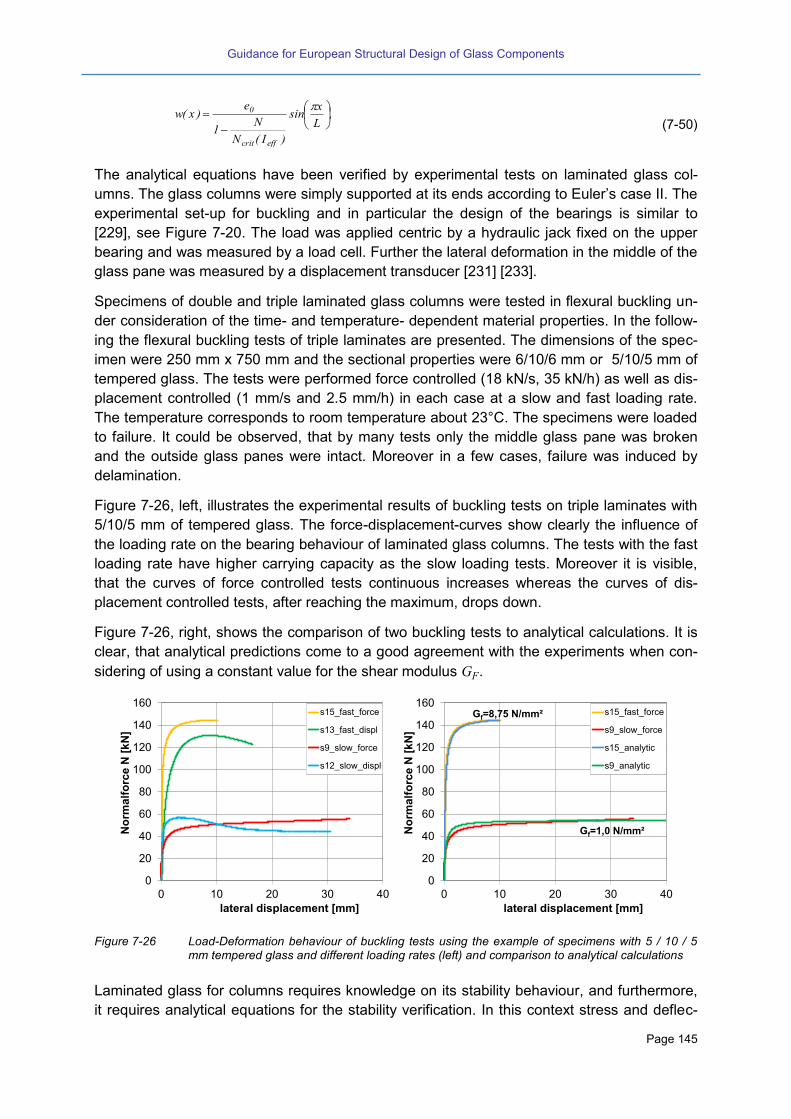
Guidance for European Structural Design of Glass Components
Page 145
.
L
xsin
)I(N
N1
e)x(w
effcrit
0
(7-50)
The analytical equations have been verified by experimental tests on laminated glass col-
umns. The glass columns were simply supported at its ends according to Euler’s case II. The
experimental set-up for buckling and in particular the design of the bearings is similar to
[229], see Figure 7-20. The load was applied centric by a hydraulic jack fixed on the upper
bearing and was measured by a load cell. Further the lateral deformation in the middle of the
glass pane was measured by a displacement transducer [231] [233].
Specimens of double and triple laminated glass columns were tested in flexural buckling un-
der consideration of the time- and temperature- dependent material properties. In the follow-
ing the flexural buckling tests of triple laminates are presented. The dimensions of the spec-
imen were 250 mm x 750 mm and the sectional properties were 6/10/6 mm or 5/10/5 mm of
tempered glass. The tests were performed force controlled (18 kN/s, 35 kN/h) as well as dis-
placement controlled (1 mm/s and 2.5 mm/h) in each case at a slow and fast loading rate.
The temperature corresponds to room temperature about 23°C. The specimens were loaded
to failure. It could be observed, that by many tests only the middle glass pane was broken
and the outside glass panes were intact. Moreover in a few cases, failure was induced by
delamination.
Figure 7-26, left, illustrates the experimental results of buckling tests on triple laminates with
5/10/5 mm of tempered glass. The force-displacement-curves show clearly the influence of
the loading rate on the bearing behaviour of laminated glass columns. The tests with the fast
loading rate have higher carrying capacity as the slow loading tests. Moreover it is visible,
that the curves of force controlled tests continuous increases whereas the curves of dis-
placement controlled tests, after reaching the maximum, drops down.
Figure 7-26, right, shows the comparison of two buckling tests to analytical calculations. It is
clear, that analytical predictions come to a good agreement with the experiments when con-
sidering of using a constant value for the shear modulus GF.
Figure 7-26 Load-Deformation behaviour of buckling tests using the example of specimens with 5 / 10 / 5 mm tempered glass and different loading rates (left) and comparison to analytical calculations
Laminated glass for columns requires knowledge on its stability behaviour, and furthermore,
it requires analytical equations for the stability verification. In this context stress and deflec-
0
20
40
60
80
100
120
140
160
0 10 20 30 40
No
rma
lfo
rce
N [
kN
]
lateral displacement [mm]
s15_fast_force
s13_fast_displ
s9_slow_force
s12_slow_displ
0
20
40
60
80
100
120
140
160
0 10 20 30 40
No
rma
lfo
rce
N [
kN
]
lateral displacement [mm]
s15_fast_force
s9_slow_force
s15_analytic
s9_analytic
Gf=1,0 N/mm²
Gf=8,75 N/mm²

Guidance for European Structural Design of Glass Components
Page 146
tion equations for double and symmetric triple laminates based on the slip differential func-
tion were derived ((7-48), (7-49) and (7-50)), in which the shear modulus GF of the interlayer
can be implemented.
The results provide a basis for the consideration of the composite action for the design of
laminated glass structures under axial loading.
7.4.5 Critical load of laminated bars under axial loads with blocked end slip
A beam in buckling with pinned ends consisting of a laminate with blocked slip between the
layers at the ends is shown in Figure 7-27. For the first instance (case A) no shear transmis-
sion between the layers along the axis is assumed. The critical load of the beam and its cor-
responding buckling length respectively the effective bending inertia is needed. For this con-
figuration the conditions at the end points are of special interest. Conversely to laminated
beams with free end slip at the end points inner moments iM and normal forces in the layers
iF occur. E.g. for symmetrical two layered laminate the relationship tFM ii 2 exists (note
that in previous considerations the thickness was denominated as “d” instate of “t”). Effective-
ly the end slip restraint leads to an increase of the critical buckling load and therefore also to
an increase of the ultimate axial force.
Figure 7-27 Laminated buckling beam, a) to c) with restraint slip at the ends, d) with free end slip
For the determination of the buckling load the end slip restraint shall be modelled by an
equivalent torsional spring. For this a half of the symmetric system can be considered as a
very slender frame, the restraint effect of the head plate (=rail or beam of the frame) on top
can be substituted by an equivalent torsional spring. As a very important point, thereby the
elongation respectively the shortening of the layers (columns of the frame) have to be taken
into account, otherwise no correct buckling shape can be found. The reason lies in the very
high slenderness of the regarded structure. Figure 7-28 shows the situation.
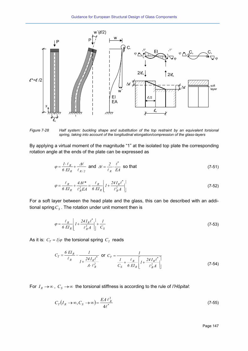
Guidance for European Structural Design of Glass Components
Page 147
Figure 7-28 Half system: buckling shape and substitution of the top restraint by an equivalent torsional spring, taking into account of the longitudinal elongation/compression of the glass-layers
By applying a virtual moment of the magnitude “1” at the isolated top plate the corresponding
rotation angle at the ends of the plate can be expressed as
2/RR
R
EI6
1
and
EA
2 *
R
so that (7-51)
A
I241
EI6EA
*4
EI6 2R
*R
R
R
2RR
R
(7-52)
For a soft layer between the head plate and the glass, this can be described with an addi-
tional spring SC . The rotation under unit moment then is
S
3R
*R
R
R
C
1
A
I241
EI6
(7-53)
As it is: 1CT the torsional spring TC reads
2R
*RR
RT
A
I241
1EI6C
or
A
I241
EI6C
1
1C
2R
*R
R
R
S
T
(7-54)
For RI , SC the torsional stiffness is according to the rule of l’Hôpital:
*
2
4,
RSRT
EACIC (7-55)

Guidance for European Structural Design of Glass Components
Page 148
In case of an elastic connection between the layers, the bending inertia increases as for bars
with free end slip. The point of inflexion moves upwards the higher the shear stiffness K of
the interlayer is until finally, this point reaches the top when K gets an infinite value. In this
case the shear gap provides full composite action and the buckling length coincides with the
system length. It is further important to mention that despite of an increasing buckling length
the critical load crP does not reduce, rather grows. It is obvious, that in this case the effect of
a higher bending inertia overbalances the effect of a higher buckling length.
Figure 7-29 Buckling bar with stiff end plate (restrained end slip) and elastic shear transmission between the layers: Position of the point of inflexion and its sectional shear forces.
The search of the buckling length respectively the position of the point of inflexion H starts
with the formulation of the slip at this point both for substructure 1 and substructure 2. The
shear forces 1V for system 1 and 2V for system 2 at the point of inflexion can be calculated.
As the bowstring of the deformed system 2 is tilted there is a further deviating shear force to
be considered, which we call V , such that
VVVVV 1*22 (7-56)
The slip formulation at point H then is, see Figure 7-29,
22
2s
2
2
s1
2s
2
1
s111 s
VVVs
(7-57)
Guidance for European Structural Design of Glass Components
Page 149
where s and s are cross-sectional parameter, see the previous chapters. From the deriva-
tion of the differential equation of slip the occurring Moment at the head plate M can be cal-
culated:
2
221 sinVV
xsinVM
(7-58)
Using the elastic torsional spring stiffness /MCT and PV
2T
21
T
21
PC
PV
C
PPVV
(7-59)
can be obtained. With the equation above, recalling that 1crPP
0
P
C1
1
21cr
T2s
2
1
2s
2
2
(7-60)
the partition of 1 and 2 has been derived.
As
21
2s
2
1
sR
icr
1
K1
IEP
and 2
*
1
(7-61)
a closed solution of 1 is rather complex, thus a determination of how the proportion of
1 to
* is, this can easily be done by trial and error. Further, by using the rule of de l´Hôpital some
special values can be obtained:
1) RI and K
11
P
C1
11
2full,cr
f,T
0, 2
*
1 (7-62)
2) 0IR and 0K
11
P
C1
11
2glesin,cr
T
0, 2
*
1 (7-63)
3) RI and 0K ; 2-layered: Rt (7-64)

Guidance for European Structural Design of Glass Components
Page 150
0;EI2
P;I2I;4
EAC s2
1
21
cr1*
2R
T
*2
*1
*2
21
2
2
1 35,0,65,0
2
31
1
This solution is in agreement with the solution given in [237] where *1 64,0 and
*2 36,0 .
It comes that the critical load does not change a lot whilst increasing the interlayer stiffness
by factors of 10. The reason lies in the increasing buckling length, parallel to the shear stiff-
ness increases. That means that the blocked slip at the end by the head plate is the predom-
inant factor and also, that the time dependent viscoelastic effect of interlayers will not play
that much important role as it does for buckling bars with free end –slip.
Finally it needs to be mentioned that all further verifications can be done as for buckling bars
with free end slip with B if the buckling factor is derived.
7.4.6 Interaction of axial loads with bending moments
Suggestions for the consideration of axial loads with bending moments for columns are given
e.g. in [239].
7.4.7 Consideration of short term – long term loading effects on the stability
Thoughts to this point are given in e.g. [238].
7.4.8 Conclusions
On the basis of the second order theory, buckling curves for glass columns are derived from
the stress equation, which could be transferred into the format of European buckling curves
for steel components. The comparison of the proposed analytic buckling curves to experi-
mental buckling tests as well as to the numerical calculations shows a good prediction of the
proposed buckling curves. For the effective imperfections the following values are proposed:
400/Le0 for heat strengthened glass and
300/Le0 for thermally toughened glass.
However, in practice, installation tolerances have always to be considered. These have con-
servatively been estimated by a value of 3.0 mm for glass columns with a thickness of 12
mm. Considering this, effective imperfection values of mm0.3400/LeHSG
0 or
mm0.3300/LeTTG
0 respectively come out. By this the basis for the implementation of buck-
ling curves as proposed in technical rules or codes are laid down.
Up to now the research work has led to results on the consideration of improved buckling
lengths, the interaction of axial loads with bending and the non-linear effect of the load dura-
tion of different loading types. However further investigations on load introduction, long term
behaviour etc. are necessary.

Guidance for European Structural Design of Glass Components
Page 151
Eurocode Outlook No. 38
(1) Instead of using a full non-linear analysis the stability assessment of glass columns can be
performed by buckling curves.
(2) The imperfection assumptions of the buckling curves should coincide with the imperfections
that are used for the alternative non-linear analysis.
(3) The imperfection assumptions for columns for glass consist of two elements comprising
a. The geometrical and inherent structural imperfection that can be measured by ex-
periments may be according to the Southwell-procedure. These imperfections can
be regarded as proportional to the length and so far can be assumed to L/400 for
HSG and L/300 for TTG respectively in sinoidal shape along the axis.
b. Unlike to other materials, due to the slenderness of glass panels additionally erect-
ing tolerances may appear in reality. However whereas in the experiments those
tolerances are often avoided. In practice they should be assumed to be a constant
value of 3.0 mm along the axis.
(4) Reliable interlayer shear stiffness values in dependence on time and temperature can be tak-
en into account.
(5) If possible the occurring end slip of the laminate should be prevented by constructive
measures (end plate bonded with epoxy resin). Otherwise the occurring end-slip should be
assessed.
(6) In case of blocked end slip the corresponding buckling length can be modified.
(7) The non-linear effect of different load duration on the buckling strength should be taken into
account unless the laminate is calculated without composite effect.
(8) The non-linear interaction of axial loads with bending moments has to be considered.
(9) The failure load prediction model should be carried according the European format and cal-
ibrated such that can be applied.
(10) Eurocode should give examples for best practice design of the load introduction points.
7.5 Beam-columns
The consideration for the buckling behaviour of beams, columns and shear panels can be
enlarged for combined loading, e.g. beam-columns.
7.6 Hybrid structures and hybrid glass components with enhanced pre-
and post-failure performance
Hybrid glass components offer enhanced pre- and post-failure performance. In general, a
hybrid glass component is composed of glass – as the main load-carrying material – and an
additive material (e.g. steel, timber, GFRP or CFRP) which is adhesively bonded to the glass
or fixed mechanically without any adhesive or sealing material. This additive material pro-
vides extra load-carrying capacity, extra stability or extra redundancy to the glass compo-
nent. However, hybrid structural component can be designed in way that structural glass
share load-bearing capacity with the constituent structural elements made of additive materi-
als, in particular wooden ones. Glass beams can for instance be provided with additional

Guidance for European Structural Design of Glass Components
Page 152
steel flanges to obtain enhanced load-carrying capacity and extra lateral torsional buckling
stability, as studied by e.g. [245][247][254] see Figure 7-30. Furthermore, glass beams can
be provided with a steel reinforcement section to obtain enhanced post-breakage perfor-
mance and extra redundancy, as under investigation by e g. [186][190], see Figure 7-30 (b)
and chapter 6.11. Moreover, hybrid steel-glass or timber-glass shear wall systems can be
created to realize hybrid structures with glass as the main stabilizing material, as studied by
e.g. [192][204][193][194], see Figure 7-31.
Various hybrid glass component solutions are currently under investigation, mainly in an ac-
ademic context. However, the number of applications in practice is currently limited and fur-
ther investigations may be needed. In this respect the adhesive bond between the glass and
the additive material and the overall response of the hybrid component is of specific interest.
(a) (b) (c)
Figure 7-30 Hybrid glass solutions; (a) steel-glass I-section beams [254]; (b) reinforced glass beam [186]; (c) glass-wood friction joint [193]
(a) (b) ©
Figure 7-31 Timber-glass composite beams; (a) beams [241]; (b) panels [242]; (c) glass-infilled frame panels [194]
A recent research project [272] considered a façade element as a framed glass pane or –
mechanically – as a slab/pane with – laterally connected edge beams.

Guidance for European Structural Design of Glass Components
Page 153
Figure 7-32 Slab/pane with laterally connected edge beams
For such a system different load paths were examined: loading uniformly along the horizontal
glass edge, loading on the glass edge concentrated near the corner, loading of the edge
beam and combinations of these load paths. It showed that for realistic dimensions of the
elements (glass and edge-beam) the load transfer directly through the edge beam is the
most effective one, combining the highest load carrying capacity with the stiffest behaviour.
Applying the vertical load directly on the edge beam, the structure can be considered as a
laterally loaded compression member, subject to buckling risk. In a parametric study the load
deformation behaviour of the vertically and laterally loaded structure was analysed. It showed
that taking only the resistance (moment of inertia) of the edge beam itself into account, would
be very uneconomic, as the glass pane adds considerable stiffness to the structural behav-
iour.
Based on these results the effective stiffness of the structure was investigated for various
situations and boundary conditions. Interpreting the effective stiffness as a joint stiffness of
the edge beam and the glass pane, it can be expressed as
EIeff EIEB beff B EIGP (7-65)
with EIEB as the bending stiffness of the edge beam, beff as the effective width of the glass
pane, B as the total width of the glass pane and EIGP as the total bending stiffness of the
glass pane.
The investigation revealed an interesting result: the aspect ratio a (width/height) is the only
decisive influence factor for the effective width of the glass. All other parameters (e.g. stiff-
ness ratios, pre-lead) only have little or no influence. The following graph shows the effective
width as a function of the aspect ratio.

Guidance for European Structural Design of Glass Components
Page 154
Figure 7-33 Effective width as a function of the aspect ratio
Having determined the initial deformation figure for the lateral load with no vertical force
applied (F 0), the load deformation behaviour of the edge beam – and with that the load de-
formation behaviour of the structure for the vertical load – can be determined by applying the
analogy of a pre-deformed compression member using the analytical solution [237].
w w0 w0
2
2 2 (7-66)
with w0 as the deformation w( ) at the centre of the edge beam and ε as
√F
EI (7-67)
with as member height, F as vertical load, and EI as the effective stiffness EIeff beff .
By using this formulation, the static calculation can be done according to EC3, taking into
account the stiffening effect of the glass pane by using EIeff instead of EIEB. Even damaged
or partially damaged structures (broken glass layers) can be considered by using a reduced
thickness for the determination of EIGP.
The combination of laminated timber frame and laminated glass presents an innovative ap-
proach for achieving improved earthquake resistance of buildings. Timber frame can be easi-
ly inserted in any type of structural system and at the same time enables the efficient and
safe load transfer from the structural system to the inserted glass panel. To achieve ade-
quate post-fracture behavior of the glass panel, heat strengthened laminated glass is used to
provide high load bearing capacity after the potential cracking of the glass during an earth-
quake or extreme wind action. Panels composed of laminated or cross-laminated timber and
laminated glass have a wide range of applications, among which the building refurbishment
and earthquake strengthening of frame structures presents only one of the possibilities. They
can be used as an integral load-bearing panel in prefabricated timber structures composed
both from solid timber panels or frame timber panels and as a shear wall in any kind of struc-
tural systems.
The research cooperation of University of Zagreb [195] and University of Ljubljana [196]
[197] resulted in development of new type of structural component made of timber frame and
laminated glass infill. The initial properties of bare frame, glass panels and glass infilled tim-
Guidance for European Structural Design of Glass Components
Page 155
ber frame have been experimentally studied, where main tests were carried out in device
presented in Figure 7-31 (c). Partners have extended research cooperation to Institute of
Earthquake Engineering and Engineering Seismology, IZIIS, Skopje,Macedonia [198] where
shake table testing of prototype structure have been carried out [199].
A universal shear wall test setup [201] (Figure 7-31 (c)) was developed and installed at Fac-
ulty for Civil and Geodetic Engineering of University of Ljubljana in 1999. The main idea of
the device was to use a gravity load induced by ballast as a constant vertical load and a dis-
placement controlled hydraulic actuator as a driver of the cyclic horizontal load. The main
challenge was to simulate realistic boundary conditions that may occur during the action of
an earthquake. In reality, the boundary conditions may change during an earthquake excita-
tion because of changes of the building characteristics due to development of damages.
Therefore, the testing device should allow the altering of boundary conditions from one to
another test run. Following this idea, the set-up can be easily adapted to various boundary
conditions applied to tested panels. Basically, three major cases of boundary conditions are
most likely to appear in reality:
Shear cantilever mechanism, where one edge of the panel is supported by the firm base
while the other can freely translate and rotate.
Shear wall mechanism, where the firm base supports one edge of the panel while the
other can translate only in parallel with the lower edge and rotation is fully constrained.
Restricted rocking mechanism, where one edge of the panel is supported by the firm
base while the other can translate and rotate as much as allowed by the ballast that can
translate only vertically without rotation.
Test set-up with adaptable boundary conditions enables testing by utilizing different loading
protocols, from simple monotonous to more complex cyclic ones. Cyclic testing can be car-
ried out following the protocols EN 12512:2001 [35], ISO 16670:2003 [36] or any other as, for
example CUREE protocol [202]. Wooden frames with glass infill were tested monotonously
following the protocol of EN 594 and cyclically according to ATC-1994 [203] applying all there
above described boundary conditions [200] [201].
For all tested specimens was common that the majority of damage was concentrated in tim-
ber frame joints, as they are the weakest part of the hybrid wall. The laminated glass panels
remained intact during the entire test. The punched steel plate connector used in one of
joints in addition to steel bolt, efficiently limited the propagation of damages and contributed
to better response of specimens in comparison to those without steel plates. Test results
shows that friction force is playing an important role in sharing resistance to in-plane acting
load with frame joints. The considerable amount of energy was dissipated by friction. Hyster-
etic response of the specimens provided the information on ductility, stiffness degradation
and viscous damping.
The whole hybrid shear wall shows considerably robust behavior. Damage propagation in
joints up to their local failure does not lead to failure of tested specimen that was able to dis-
sipate the induced energy due to wood-to-glass friction. Moreover, performance of joint de-
tailing can be further improved to achieve higher deformation capacity. Learning from exper-
iments and from the mathematical model that is under development, new series of speci-
mens will be tested. The major improvement of next specimens will be in critical details of
frame joints.
Guidance for European Structural Design of Glass Components
Page 156
The objective of above described racking tests was to obtain data for development of compu-
tational model of tested type of structural element that can be used for prediction of inelastic
response of buildings made of glass-infilled timber frames on seismic action. To obtain dy-
namic parameters and study the phenomena of response of this type of structures on seis-
mic action, shaking table tests were carried out [199].
Box-type models were constructed of two glass-infilled timber frames made of simple lami-
nated wood and corner joints fixed by single bolt and punched metal plates. The mass of 9.6
tons was added atop of model. Four types of real earthquake actions were subsequently
applied to model: El Centro 1940, N-S, California, USA; Petrovac 1979 Montenegro; Kobe
1995 E-W, Japan, and Friuli 1976 E-W, recorded in Tolmezzo, Italy. The inelastic behavior of
model was achieved after application of full scale Kobe earthquake that was applied last in
subsequent application of other three full-scale earthquakes. The damages caused by Kobe
earthquake were limited to upper joints of frame, but their extent was much lower than in the
case of racking load at its ultimate stage.
The performed tests showed clearly the behavior of the glass infilled wooden frames and
failure mechanism under strong earthquake motion. It is manifested by slip of the glass along
the wooden frame and permanent deformations of the wood, without any damage in the
glass. The panels dissipated energy trough sliding of the glass, development of damages in
frame corners and activating of the still connectors that anchor frame to r. c. fundaments.
The seismic tests proved that the innovative composite panel could be considered as promis-
ing structural system, in which the load-bearing structural glass and the wood are working
together, conforming to each other in beneficial manner. The dynamic tests results showed
very good agreement with the results obtained during the racking tests of the panels.
Regarding design of wood-glass panels as wall diaphragms, all assumptions from EN 1995-
1-1 Part 9.2.4.1.(1)–(7) [41] general could be used. The in-plane design shear (racking)
strength against a force acting at the top of a cantilevered wall that is secured
against uplift and sliding by vertical actions and/or anchorage, should be determined using
the simplified method for the wall construction defined in EN 1995-1-1; Part 9.2.4.3.1 .
The external forces and (see Figure 7-34) from the horizontal action Fi,v,Ed on
wall should be determined from EN 1995-1-1 (9.32)
(7-68)
where is the height of the wall.
These external forces can be transmitted to either the adjacent panel through the vertical
panel to panel connection or to the construction above or below the wall. When tensile forces
are transmitted to the construction below, the panel should be anchored with stiff fasteners.
Compression forces in the vertical members should be checked for buckling in accordance
with EN 1995-1-1, (6.3.2.) Where the ends of vertical members bear on horizontal framing
members, thecompression perpendicular to the grain stresses in the horizontal members
should be assessedaccording to EN 1995-1-1 (6.1.5.)

Guidance for European Structural Design of Glass Components
Page 157
Figure 7-34 Distribution of forces acting on panel due to lateral loading

Guidance for European Structural Design of Glass Components
Page 158

Guidance for European Structural Design of Glass Components
Page 159
8 Joints and Connections
8.1 General
For primary structures, joints are playing an important role for the transfer of the sectional
forces from one element to another. The most important jointing techniques are:
Mechanical transmission of single forces by bolts in drilled holes. The clearance between
shank and hole-bearing has to be filled with a well-fitting hard plastic bush or a mortar
that eliminates detrimental stress-peaks. Care is needed with mortar selection as a mate-
rial which is too hard can have detrimental effects if the forces on the bolt are eccentric.
Bolted connections can easily be disassembled without damage of the main components
of the connection.
Mechanical transmission of distributed forces by friction joints. Friction joints consist of
metal clamping devices and a friction producing interlayer between the metal- and glass-
surface. Friction is produced by pre-stressing normal to the planes; therefore, shear forc-
es can be activated. Friction joints can easily be disassembled without destroying the
components of the joint.
Transmission of single, linear and areal distributed forces by adhesive bonding. Adhesive
bonding allows a variety of jointing details so that at the same time it acts mechanically
and produce tightness in the joint. However they cannot be disassembled without de-
stroying the connection.
By the use of jointing techniques single glass-panes can be assumed such that they form a
profile of bending section. In that case the forces are continuously, the inner static state is
predominantly non-determined and in case of spot damages at the joints often a sufficiently
stress redistribution allows for a robust joint.
Generally to attain sufficient robustness, in advance to the design of a joint, the damage tol-
erance of the joint and the elements to be jointed together should be clarified.
For point-supported glass panes additionally the bending resistance in the area of the hole
edge is also of importance. In national regulations, if there are rules of design of structural
glass, mostly only the design of standard secondary elements of glass is specified. For point-
supported glass panes, additional local stress occurs.
8.2 Bolted connections
In-plane load glass panes are used more and more due to its high mechanical capacity, Fig-
ure 8-1, therefore also joints have to be developed that allow for a transmission of high loads.
For this bolted connection are very suitable. Therefore the analytic needs to be shown of how
a bolt in shear procedures what pressure distribution in the bearing of the whole and further,
of what the stress pattern in the glass is. As always, due to the missing stress-redistribution
ability of glass, the domain of the elasto-statics cannot be left. This will lead to rather com-
pleted equations that in the end need to be simplified.
In the following an analytical model will be proposed and should be understood as a com-
plementary tool to the Finite-Element-Calculation.

Guidance for European Structural Design of Glass Components
Page 160
Very important is that basically the prediction of the real stress peaks in and in the vicinity of
the contact areas of shank to bearing-wall is not possible. Therefore the principle of avoiding
steel-glass contact has to be further obeyed thoroughly. This means that always a durable,
stress-peaks-eliminating interlayer material (plastics-modified mortar) has to be provided in
the clearance between bolt-shank and glass-bearing.
Figure 8-1 Details of bolt connections of glass in the entrance glazing of the New Berlin main station
8.2.1 Detailing of a structural bolted connection of bolts in shear in glass holes
The design layout of a bolted connection should always be double-lapped, so that eccentrici-
ty moments and non-welcome prying forces can be avoided. The components of a bolt in
shear in glass holes are shown in Figure 8-1.
Generally structural glass panes subject to be assemble by bolted connections are of lami-
nated glass. Using laminated glass with drilled holes, a certain backfill of the holes can be
expected in the range of tolerances of EN ISO 12543 [13]. This results into the effect of a
non-uniform pressure distribution. However, the mortar in the clearance equalizes this effect,
Figure 8-1, between mortar and bolt shank there has to be provided an additional ring of al-
uminium with the thickness of about talu = 2.0 mm.
The thickness of the mortar (= half of clearance) should be in the range of 5.0 < tmortar < 12.0
mm. Using HILTI-Hit-mortar, then in this range an elastic load deformation behaviour can be
assumed.
Remark: the use of only plastic – or aluminium ring might be advantageous for simplicity rea-
sons during assembly, however this is not to be recommended as amount and scatter of the
reachable ultimate loads are very unfavourable [248]. The following explications therefore,
only refer to the detailing as described above Figure 8-1.
8.2.2 Analytical verification of a bolted connection in glass
So far, bolted connections have been exclusively calculated by FEM. Analogous to the calcu-
lation of point-supports, special care must be taken for the choice of elements and meshing
the FE-grid. The question of an adequate and sufficient FE-model is frequently a matter of
discussion. For despite of the consideration of the mortar in the FE-model, slight variations of
element-type and meshing produce significant stress derivations. Up to now there are no real
rules for the choice of the “correct” available FE-model.
Guidance for European Structural Design of Glass Components
Page 161
Because of this, rather often, there is the opinion that bolted connections only can be de-
signed by testing. This disregards the existence of analytical calculation means, that - ade-
quately prepared – deliver good solutions with regard to time consumption and preciseness.
However, they are only applicable to “standard” geometrics.
The following explications are essentially based on [250]. At first the analytical basics on the
elastic solid differential equations are touched and then the practical application and prepara-
tion is presented (procedural recipe) [248] [249] [251] [252].
8.2.3 Elastic response of an in-plane loaded solid pane
The transformation of AIRY´s differential equation for an in-plane loaded solid pane (without
temperature resistant)
2
2
2rr
1
rr
1
(8-1)
and the stress function according to AIRY
2
2
(8-2)
into polar coordinates leads to stresses
r
1
rr
(8-3)
= radial distance
and = angle of radius
By that the stress-states of glass panes with arbitrary geometry can be described. However,
what makes the procedure difficult is the search for the function of AIRY.
A simple reduction of the procedure can be found for a bolted connection with n bolts in a
row in a glass strip of the width bm, Figure 8-2. The strip is loaded at the butt with the total
force P total. Considering a single hole m with the force P m, then – with sufficient distance to
the hole-boundary a continuous load in sections perpendicular to the row-axis before and
behind the hole can be observed: p m before
and p m be , the amount of these distributed
loads is still unknown. This solid element is subject to a stress-state that can be split up into
two parts (Figure 8-2):
a non-symmetric part (stress-state 1) that shows bearing stresses and net-section
stresses,
a symmetric part (stress-state 2) that shows only net-sections stresses.
In order to attain correct results compared to the original configuration, the boundary loading
for the non-symmetrical state 1 are defined with “ ” and for the symmetrical state 2 with “ ”
to
li,m,xpp2
1q (8-4)

Guidance for European Structural Design of Glass Components
Page 162
remxppq ,,2
1 (8-5)
m
mx
mxb
Pp
,
, : (8-6)
Stress state 1 Stress state 2
Figure 8-2 Definition of the stress states 1 und 2
Stress State 1. Firstly for a plate element loaded by a bolt in bearing the pressure distribu-
tion p has to be determined, Figure 8-3. This can be realized by a cosinus-series [250]
[251]:
ncosppp1n
n,HoH
(8-7)
Thereby it is assumed to have no clearance. In the series, Figure 8-3, the pressure distribu-
tion of each element is in internal equilibrium except of the element )1cos(p 1,H , this is in
equilibrium with the outer load xP . Apart of ( 0.1p0 ) only the element 1,Hp can be deter-
mined via the boundary condition.
x2
2
01,H Pdcosap
(8-8)
resulting into
a;a
Pp x
1,H
= hole radius (8-9)
All other elements cannot be determined analytically due to the lack of further boundary con-
ditions. Integrating over 0÷2 there are only useless solutions with

Guidance for European Structural Design of Glass Components
Page 163
0p....ppp u,H3,H2,H1,H ; respectively for other integration-arcs the boundary conditions
are lacking. To overcome this, the FEM can be used producing a vector
n
1n
1
0
H
pp
pp
pp to pP
av
x
(8-10)
with ̅ according [249]. A sufficient accuracy will be reached when approximately 20+1 serial
elements are determined. By this the bearing pressure Hr p),a( are known under the
assumption of friction-free conditions. These pressures then can be introduced into the func-
tion of AIRY ),r(H at the bearing are by
0,rH (8-11)
The radial, tangential and shear stresses in the plate (resulting from the non-symmetric load-
ing) can be determined
ncosr
an2n
r
ap
t2
1
cosr
a
1
3
r
ap
t4
1
rt
ap,r
2
2
n
n
2nn
2
2
12
20
H,r
(8-12)
ncosr
an2n
r
ap
t2
1
cosr
a1
r
ap
t4
1
r
a
t
p,r
2
2
n
n
2nn
2
2
12
20
H,
(8-13)
nsinr
a1n
r
ap
t2
1
sinr
a1
r
ap
t4
10,r
2
2
n
n
2nn
2
2
1H,,r
(8-14)
with
,r polar coordinates, seen from the hole centre
ip terms of the series
a hole radius
t thickness of the glass pane
Poisson´s ratio
The solutions are exact if the dimensions of the considered glass element are infinite.

Guidance for European Structural Design of Glass Components
Page 164
Figure 8-3 Stress State 1
Stress State 2. The symmetrical stress state originates from an infinite plate with hole under
tension and can also be determined by solving of with 0 . The solutions for r ,
and ,r are
2cos
3411
2,
4
4
2
2
2
2
,r
a
r
a
r
a
t
prNr (8-15)
2cos
311
2,
4
4
2
2
,r
a
r
a
t
prN (8-16)
2sin32
12
,4
4
2
2
,
r
a
r
a
t
prr (8-17)
see Figure 8-4.
Stress distribution and
Figure 8-4 Stress State 2
For a plate element with a finite width mb and with )b2/()ap()b2/(P2/p m1mxx the follow-
ing results ( 1p = series element from antimetric loading).
2cos
r
a3
r
a41
r
a1
bt4
ap,r
4
4
2
2
2
2
m
1N,r (8-18)
2cos
r
a31
r
a1
bt4
ap,r
4
4
2
2
m
1N, (8-19)

Guidance for European Structural Design of Glass Components
Page 165
2sinr
a3
r
a21
bt4
ap,r
4
4
2
2
m
1N,,r
(8-20)
Superposition and -values. As explained, the superposition of the symmetric and anti-
metric stress state allows for the determination of the resulting stress state. Thereby the sys-
tem definition is such, that the antimetric stress state results from the single-bolt-
consideration and is split up into a pulling and a pushing edge loading. The symmetric stress
state is a pure net-section stress due to the stresses passing the hole. With the product mK ∙
2/p m,x the amount of the passing stressing is described as a multiple of (for the rest of
the forces mi,xP ). Then, by 2/p2 m,x from the antimetric state a bolt force can be put. It
becomes clear, that the method is also valid for non-equal forces i,xP . For the values mK the
general format reads:
1P
P
2Km,x
m
1ii,x
m
(8-21)
E.g. for a hole at the edge the K-value is K1 so that there is not further loading on the
edge. For the neighbouring hole K2 can be obtained, see Table 8-1.
Table 8-1 -values
Equilibrium system Km-value
K1 = 1
K1 = –1
for Px,1 = Px,2 it is:
K1 = 1
K2 = 3
for Px,1 = Px,2 it is:
K1 = –1
K2 = –3
For ambiguous holes m n
12,
1
,
mx
m
i
ix
mP
P
K
For ambiguous holes m n
mx
m
i
ix
mP
P
K,
1
,
21
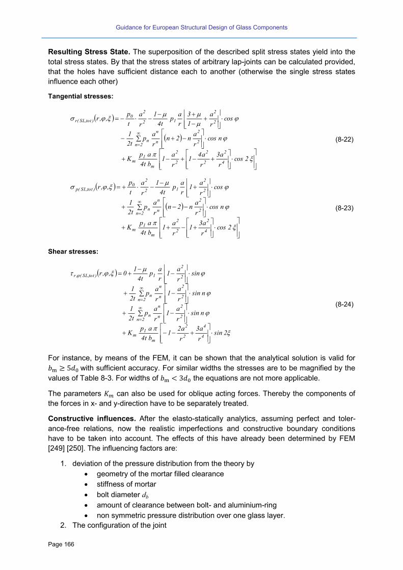
Guidance for European Structural Design of Glass Components
Page 166
Resulting Stress State. The superposition of the described split stress states yield into the
total stress states. By that the stress states of arbitrary lap-joints can be calculated provided,
that the holes have sufficient distance each to another (otherwise the single stress states
influence each other)
Tangential stresses:
2cosr
a3
r
a41
r
a1
bt4
apK
ncosr
an2n
r
ap
t2
1
cosr
a
1
3
r
ap
t4
1
r
a
t
p,,r
4
2
2
2
2
2
m
1m
2
2
n
n
2nn
2
2
12
20
)tot,SL(r
(8-22)
2cosr
a31
r
a1
bt4
apK
ncosr
an2n
r
ap
t2
1
cosr
a1
r
ap
t4
1
r
a
t
p,,r
4
2
2
2
m
1m
2
2
n
n
2nn
2
2
12
20
)tot,SL(p
(8-23)
Shear stresses:
2sinr
a3
r
a21
bt4
apK
nsinr
a1
r
ap
t2
1
nsinr
a1
r
ap
t2
1
sinr
a1
r
ap
t4
10,,r
4
4
2
2
m
1m
2
2
n
n
2nn
2
2
n
n
2nn
2
2
1)tot,SL(,r
(8-24)
For instance, by means of the FEM, it can be shown that the analytical solution is valid for
with sufficient accuracy. For similar widths the stresses are to be magnified by the
values of Table 8-3. For widths of the equations are not more applicable.
The parameters can also be used for oblique acting forces. Thereby the components of
the forces in x- and y-direction have to be separately treated.
Constructive influences. After the elasto-statically analytics, assuming perfect and toler-
ance-free relations, now the realistic imperfections and constructive boundary conditions
have to be taken into account. The effects of this have already been determined by FEM
[249] [250]. The influencing factors are:
1. deviation of the pressure distribution from the theory by
geometry of the mortar filled clearance
stiffness of mortar
bolt diameter db
amount of clearance between bolt- and aluminium-ring
non symmetric pressure distribution over one glass layer.
2. The configuration of the joint
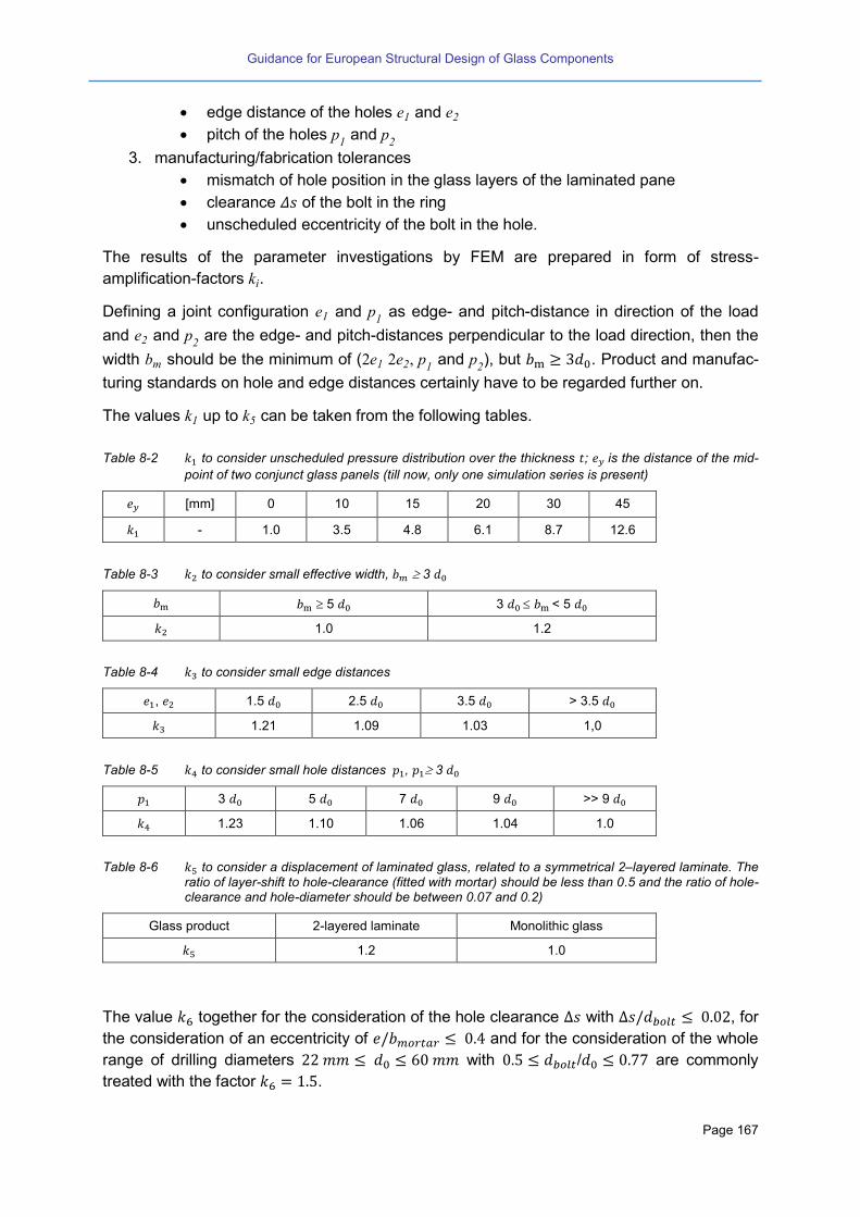
Guidance for European Structural Design of Glass Components
Page 167
edge distance of the holes e1 and e2
pitch of the holes p1 and p
2
3. manufacturing/fabrication tolerances
mismatch of hole position in the glass layers of the laminated pane
clearance of the bolt in the ring
unscheduled eccentricity of the bolt in the hole.
The results of the parameter investigations by FEM are prepared in form of stress-
amplification-factors ki.
Defining a joint configuration e1 and p1 as edge- and pitch-distance in direction of the load
and e2 and p2 are the edge- and pitch-distances perpendicular to the load direction, then the
width bm should be the minimum of (2e1 2e2, p1 and p2), but . Product and manufac-
turing standards on hole and edge distances certainly have to be regarded further on.
The values k1 up to k can be taken from the following tables.
Table 8-2 to consider unscheduled pressure distribution over the thickness ; is the distance of the mid-
point of two conjunct glass panels (till now, only one simulation series is present)
[mm] 0 10 15 20 30 45
- 1.0 3.5 4.8 6.1 8.7 12.6
Table 8-3 to consider small effective width, 3
5 3 < 5
1.0 1.2
Table 8-4 to consider small edge distances
, 1.5 2.5 3.5 > 3.5
1.21 1.09 1.03 1,0
Table 8-5 to consider small hole distances , 3
3 5 7 9 >> 9
1.23 1.10 1.06 1.04 1.0
Table 8-6 to consider a displacement of laminated glass, related to a symmetrical 2–layered laminate. The ratio of layer-shift to hole-clearance (fitted with mortar) should be less than 0.5 and the ratio of hole-clearance and hole-diameter should be between 0.07 and 0.2)
Glass product 2-layered laminate Monolithic glass
1.2 1.0
The value together for the consideration of the hole clearance with , for
the consideration of an eccentricity of and for the consideration of the whole
range of drilling diameters with / are commonly
treated with the factor .
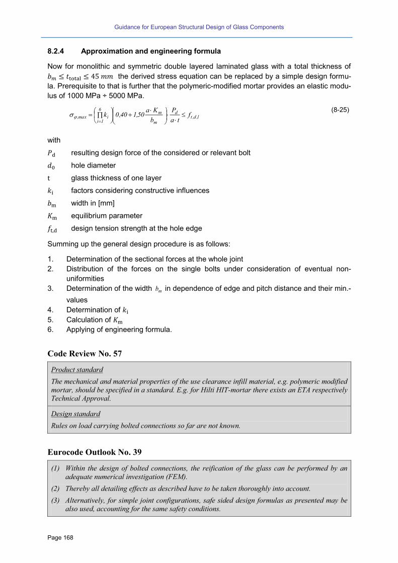
Guidance for European Structural Design of Glass Components
Page 168
8.2.4 Approximation and engineering formula
Now for monolithic and symmetric double layered laminated glass with a total thickness of
the derived stress equation can be replaced by a simple design formu-
la. Prerequisite to that is further that the polymeric-modified mortar provides an elastic modu-
lus of 1000 MPa ÷ 5000 MPa.
l,d,t
d
m
m6
1iimax, f
ta
P
b
Ka50,140,0k
(8-25)
with
resulting design force of the considered or relevant bolt
hole diameter
glass thickness of one layer
factors considering constructive influences
width in [mm]
equilibrium parameter
design tension strength at the hole edge
Summing up the general design procedure is as follows:
1. Determination of the sectional forces at the whole joint
2. Distribution of the forces on the single bolts under consideration of eventual non-
uniformities
3. Determination of the width mb in dependence of edge and pitch distance and their min.-
values
4. Determination of
5. Calculation of
6. Applying of engineering formula.
Code Review No. 57
Product standard
The mechanical and material properties of the use clearance infill material, e.g. polymeric modified
mortar, should be specified in a standard. E.g. for Hilti HIT-mortar there exists an ETA respectively
Technical Approval.
Design standard
Rules on load carrying bolted connections so far are not known.
Eurocode Outlook No. 39
(1) Within the design of bolted connections, the reification of the glass can be performed by an
adequate numerical investigation (FEM).
(2) Thereby all detailing effects as described have to be taken thoroughly into account.
(3) Alternatively, for simple joint configurations, safe sided design formulas as presented may be
also used, accounting for the same safety conditions.

Guidance for European Structural Design of Glass Components
Page 169
(4) For this the application boundaries in dependence of the calculation theory should clearly be
described.
(5) Eurocode should give examples or indications for best practise design.
8.3 Friction Joints
Friction joints are a very interesting alternative for the transmission of shear forces from pane
to pane. They are considerably flexible, as with friction shear forces can be transmitted not
only “discontinuously” but also linearly or “continuously”. By clamping along the whole edges
of glass panes large “profiles” of glass are obtained, see Figure 8-5. Very beneficial is that
they are detachable. With the respective detailing at the edges (step formed edges of lami-
nated glass panes) they even do not need any holes for pre-stressed bolts.
Figure 8-5 Example: Glass fins of the façade of Terminal 2E of the Airport “Charles de Gaulle”, Paris

Guidance for European Structural Design of Glass Components
Page 170
Figure 8-6 Triangular glass stele with friction joints at the edges
The principle of friction joints in glass structures refers to that of pre-stressed joints in steel
structures. Pre-stressing of the contact surfaces by high-strength-bolts of grade 8.8 or 10.9
enables considerably high friction forces for the transmission of shear stresses. The layout of
a friction connection is always realised by the use of clamping laps of steel, stainless steel,
aluminium or rarely with titanium. Therefore, in the gap between metal lap and glass a spe-
cial interlayer material has to be provided. This interlayer must be compressible, durable, and
reliable, with low creep behaviour and at the same time able to produce a sufficient high fric-
tion coefficient. It is clear that this interlayer should also provide a good stress distribution
effect ensuring a smooth stress introduction with no detrimental stress peaks. Furthermore
sufficient high friction coefficients should be developed. Finally steel-glass-contact has to be
avoided both in the friction gap as well as in the hole where possibly a pre-stressed bolt is
located.
The layout of discontinuous friction joints should have only two shear gaps. A positive effect
is that the friction effect then is “doubled”. The following example may show the potential
shear transmission capacity of a clamping point with three bolts M20, 10.9, each of them with
a pre-stressing force Rp . Having two shear planes, in each of them a special non-
creeping prestress-able and durable interlayer material is located, e.g. “Klingersil C 42” of
thickness with a friction coefficient of about , the resulting characteristic
shear force resistance of this joint would be
SRk nS nb 0.1 1 0 2 0.1 1 0 1 0 KN
For the design value a safety coefficient has to be considered, ranging between
and . Apart from the above mentioned mechanical and durability properties a proper
and thorough cleaning of the glass surface is necessary (grease-free and dirt-free). The

Guidance for European Structural Design of Glass Components
Page 171
same applies for the steel surfaces; the surface-evenness has to fulfil highest requirements.
Each step of the fabrication has to be well documented and proofed.
Suitable glass qualities may be heat strengthened or thermally toughened glass. The glass
surface must not be roughened by grinding, pickling or acid treatment (possibly to improve
the friction coefficient), as the so induced surface damages reduce significantly the glass
strength. Laminated toughened glass should not be clamped over the whole glass layer
compound (package), because of the reduction of pre-stress by creep of the interlayer. Even-
tually, if laminated glass is used, it is recommendable to provide a stepwise edge detail such
that the inner (load carrying glass layer) can directly be clamped. If punctual (discontinuous)
joints are used together with laminated glass, the protective glass layers should be spared in
such way that the steel-laps can be integrated in the cross-section of the glass.
The drillings should be oversized, so that tolerances from manufacturing and mounting as
well as from eventually occurring displacements under load do not lead to a steel-glass-
contact. For this, also a protection layer surrounding the shank of the bolt should be provid-
ed. Further, the clamping lap surfaces should be even, possibly milled, the laps themselves
relatively stiff, such that the force transmission can be enabled “as calculated”.
Beside of the friction verification, the verification of the glass stresses in the area of the joint
(net-section, bearing area) has to be carefully be performed. This is – in most cases – to be
done by adequate FEM-modelling and eventually by additional testing. For a pre-design it
may be indicated that especially in case of long, acting joints under a single load (dependent
on the elasticity/plasticity of the configuration) stress peaks may occur at the ends of the
joints. These stress- and force-peaks may reduce the overall shear force resistance of the
joint.
Eurocode Outlook No. 40
(1) Within the design of friction connections, different failure modes have to be considered
a. Failure due to slipping
b. Glass failure
Both failure modes have to be assessed using elastic theory.
(2) Only materials with assessed mechanical properties and durability should be used.
(3) The preparation of the friction joints should be sufficiently controlled during fabrication.
(4) Post breakage residual capacity should be ensured.
8.4 Adhesive bonding
8.4.1 General
Steel is a predictable, well researched material for structural applications, whereas glass is
an elastic and brittle material without any capacity for plasticizing, less well researched for
structural uses and not amenable to simplified design. To benefit from the advantageous
behaviour of both materials, adhesive bonding as an innovative joining technique becomes
increasing important and popular. Hybrid joining with bonding technique allows for contempo-
rary transparent and load bearing structures where each material is used in an optimized

Guidance for European Structural Design of Glass Components
Page 172
way according to its material properties. These hybrid elements offer main advantages re-
garding load carrying capacity, stability behaviour, ductility and robustness.
The bonding technology itself is a modern solution to connect different materials without en-
ergy input or weakening the cross section by holes. It is used in other industry such as auto-
motive or aviation industry as well as the ship building industry with great success and has
been established there for years. The connection of steel sheeting or steel profiles and glass
structures has been already applied there, for example bonding the windscreens of cars,
busses, trucks or trains on the load bearing substructure in order to increase the global tor-
sional stiffness.
On the contrary in civil and façade engineering bonding is still predominantly used for sealing
applications or for bonding of structures with minor structural importance (tiles, parquets,
dowels and bolts). One positive example for the use of structural bonds in civil engineering is
the reinforcement of concrete structures with bonded steel or CFRP sheets. In façade engi-
neering structural silicone glazing (SSG) applications with “structural” silicones have been
successfully applied since 30 years, but in the majority of cases with additional mechanical
retaining systems. That is why and where the recent research projects and innovative build-
ing projects come in [253] – [264].
First of all, compared to conventional joining techniques in glass and steel constructions like
bolted connections or welding, bonded joints show the following major advantages and dis-
advantages:
Connection of materials with different properties (hybrid connection of steel and glass)
Components are not weakened by holes (simultaneous saving of costs)
Constant stress propagation caused by a continuous connection
Vibration damping due to the lower Young´s-modulus of the bonding
Saving of weight caused by the absence of bolts and the use of thinner raw material
Economy of space, lightweight construction
Visual appearance is not disrupted by fastenings and connectors
Compensations of tolerances
Lower resistance compared to the connected materials
Elaborate manufacturing process and surface pre-treatment
Durability influenced by ageing, high temperature, humidity and UV-radiation
Long-term behaviour influenced by creeping
Limited fire-resistance
The disadvantages must be balanced or minimized by an appropriate joint design such as
sufficient bonding geometries, appropriate loadings (predominant shear, avoidance of peel
loadings, limited temperature loadings) and adequate adhesive selection. Care needs to be
taken when considering adhesives with modulus of 50 MPa or greater, as these are capable
of causing glass failure by “plucking” glass if the interface is imperfect and the forces on the
adhesive joint are eccentric. Especially in other application fields a large number of bonding
materials is available that would be appropriate for use in structural steel applications,
whereas cold hardening one- or two-component adhesives or UV-curing ones are the most
practical for structural application for civil engineering aspects.

Guidance for European Structural Design of Glass Components
Page 173
8.4.2 Types of adhesive
Requirements on adhesive layer are mainly focused on strength and stiffness so far but in
particular have to take into account the deformation capability. Consequently the whole
bonded joint has to be rigid enough to provide an optimal structural interaction between both
substrates, but on the other hand it has to be flexible enough to redistribute the stress peaks
in critical points and to compensate pertinent different temperature elongation.
Concluding the cured bonded joint has to meet the following static and constructional re-
quirements:
Load transfer of primarily shear forces (peel forces and eccentricities should be avoided if
possible),
Reduction of stress peaks (by sufficient deformation capability or ductile elasto-plastic
behaviour of the adhesive material and/or respectively geometrical design of the adhe-
sive connection),
Compensation of constraint forces due to possible thermal expansion,
Compensation of fabrication tolerances (gap-filling behaviour).
Common adhesives can be divided according to their modulus of elasticity and shear modu-
lus into flexible-elastic (i.e. silicones, modified silicones and polyurethanes) and rigid (i.e.
epoxy resin, acrylates). Stiff adhesives offer extremely high strength but very low elongation
in comparison with elastic adhesives, which show elongation at break even more than 250%.
A new development in the field of stiff cross-linked adhesives is toughened modified ones
with considerable enhanced ductility.
Concluding there are four main adhesives systems applicable for steel and façade struc-
tures:
Epoxy resins
Polyurethanes
Acrylates
Silicones
For these groups there do already exist a huge range of possible adhesives with completely
different curing mechanism, mechanical behaviour, ageing resistance, application behaviour,
etc. In addition, stiff ionomer or structural transparent addition cured silicon materials are
currently gaining interest for creating adhesive connections between glass and metal com-
ponents [267].
Originally, adhesives classified according to their chemical structure or curing mechanism
[265]. From an engineering point of view an adhesive classification according to the final pol-
ymeric structure is more expedient. Such more engineering-like attempt is e.g. made in [269]
which distinguishes between elastomers, thermoplastics and duromers. Whereas thermo-
plastics do not show cross-linking between the molecular chains, elastomers are slightly and
duromers are highly cross-linked. Hereby elastomers and duromers are in amorphous state
while thermoplastic can present amorphous or semi-crystalline state. To describe the me-
chanical behaviour of amorphous polymers three temperature ranges are distinguished:
energy-elastic range
glass transition temperature

Guidance for European Structural Design of Glass Components
Page 174
entropy-elastic region.
Those three regions are described by measurement of the glass transition and its character-
istic delaminating value glass transition temperature gT . Normal procedures for its determi-
nation are the Differential Scanning Calorimetry (DSC), the Dynamic-Mechanic-Analysis
(DMA) or the Thermo-mechanical Analysis (TMA) [260].
Table 8-7 attempts to classify common used adhesive systems regarding the applicability for
steel-glass joints – as far it is possible at all in such a general manner. Especially polyure-
thanes show a wide spectrum of different properties, so that a valuation is hard to be made.
Table 8-7 General comparison of different adhesive systems [262]
Tension
and shear strength
Stiffness Ductility Viscosity Temperature
resistance Ageing be-
haviour UV re-
sistance Transparency,
colour
Epoxy resin + + + + + + + + + + + + + + + + +
Poly-urethane
+ + + + + + + + + + + + + + + + +
Acrylate + + + + + + + + + + + + + + + + + + +
Silicone + + + + + + + + + + + + + + + +
Figure 8-7 shows a general correlation between elastic properties and Young´s modulus,
whereupon a decrease of the Young’s modulus from two component epoxy resins to one
component polyurethanes simultaneously goes along with a ductility and deformability in-
crease.
Figure 8-7 Connection between stiffness and elasticity for common adhesive systems [260]
Practical application of different types of polymer adhesives depends on their behaviour un-
der loading. During the selection, special emphasis has to be devoted to the UV stability and
long-time behaviour of chosen adhesives. UV unstable adhesives, like most of the polyure-
thanes, have to be protected from UV lights by using special primer coating also on the side
of the glass pane, because there is a risk of UV lights propagation also by the reflection in-
side the glass pane.
From the author´s view definitely two-component adhesives or adhesives with booster sys-
tem should be used for bonded structural glass connections, where the width of the connec-
tion is too big (over 30 mm) for humidity curing. From previous research came out, that one-
component adhesives (mainly polyurethanes), which are cured by air humidity, cannot hard-
en for depths wider than ca. 15 mm in a reasonable period of time. The booster component
provides uniform hardening of the adhesive layer, process of curing doesn’t depend on air

Guidance for European Structural Design of Glass Components
Page 175
humidity and the whole curing is finished in hours and not in days as for one component ad-
hesives. Alternatively UV-curing adhesives can be used which cure on demand, but in many
cases show significant shrinkage during the curing process.
Another important task of the connection design is to find an optimal adhesive thickness,
which fulfils the requirements on stiffness and load carrying capacity, provides sufficient
elongation (or shear strain) and also compensates possible geometrical imperfections and
balances tolerances of the connected surfaces during the fabrication. All adhesives should
be also chosen regarding to their open time and pot-time, which is very important in respect
to fabrication criteria. Some of adhesives can be applied by gap-filling, but other more vis-
cous ones have to be compressed by the components that have to be connected. The final
choice of adhesive is additionally influenced by arising temperature elongations as well as
susceptibility for creeping and ageing.
Ageing is a process that strongly depends on the adhesive system. Ageing, corrosion and
temperature changes occur under natural atmospheric exposure. According to the climatic
zone these effects are more or less pronounced and can lead to chemical and molecular
changes in the adhesives structure. Commonly affected are the boundary layer and the ad-
hesion between adhesive and substrate surfaces, but there is also a considerable influence
to the cohesion of the adhesive itself. Besides a reduction of the adhesion and a tendency for
adhesive interface failure because of peeling stresses or stress peaks, ageing effects go
along with embrittlement and a decrease of strength.
8.4.3 Present state of standardization
On European level the European Organization for Technical Approvals (EOTA) was estab-
lished as an umbrella organization that is responsible for the European standardization pro-
cess. It consists of the regulatory and certifying authorities of each single member state,
which are responsible for the granting of European Technical Approvals. Germany e.g. is
represented by the Deutsches Institut für Bautechnik (DIBt).
Main task of the EOTA is the development of guidelines for European Technical Approvals
(ETAGs – European Technical Approval Guidelines), the coordination of the granting proce-
dure of European Technical Approvals (ETAs) and the continuation and survey of existing
ETAs.
In European Technical Approval Guidelines (ETAG) for the member states the specific char-
acteristics of products or product families are defined and how to use them. They contain
product requirements and information about necessary test methods and evaluation criteri-
ons for the test evaluation.
Structural bonded glass and façade structures are regulated by the ETAG 002 [269]. This
European Technical Approval Guidelines represents a guidance for the European technical
approval of Structural Sealant Glazing Systems and is subdivided into three parts:
Part 1: Supported and unsupported systems
Part 2: Coated Aluminium Systems
Part 3: Systems incorporating profiles with thermal barrier
Here the structural glass facade is considered as a composite structure of glass, adhesive
and substructure, where the adhesive connection is exclusively carried out as linear, circum-
Guidance for European Structural Design of Glass Components
Page 176
ferential and factory-made silicon joint. In the meantime acrylic foam tapes are also in the
scope of application according to ETAG 002.
The general application of theses structural bonded façade elements is distinguished in sup-
ported or unsupported glass elements, where the former implies an extra support for dead
loads. For insulated glass or laminated glass every single pane must be vertically supported
supplementary. Mechanical restraint system may be installed for cases of adhesive failure
depending on the supplementary national requirements.
Today there are some single applications of bonding in façade engineering which are gener-
ally known as Structural Sealant Glazing Systems (SSGS), where “structural” silicones or
acrylic adhesive foams are used for joining stainless steel or aluminum substructures with
glass panes. All existing structures for building envelopes are commonly in compliance with
the ETAG 002 Guidelines [269]. Besides the narrowly limited uses cases according to ETAG
002 there are some realized-reinforced glass beam projects [270]. In principle the application
of bonded steel-glass structures is possible for a lot of façade, roofing and ceiling compo-
nents, which must offer transparency and load-bearing functions and which were not gov-
erned by fire resistance requirements.
Code Review No. 58
ETAG 002 [269]:
Devices to reduce danger in the event of bond failure may be re uired by national regulations”.
Application rules for ETAG 002 [269] in Germany:
Up to 8 m only type 1 and 2 facades with self-weight support are admitted, above 8 m only fa-
cades of type 1 with retaining device to reduce danger in case of bond failure
Façade type 3 and 4 without self-weight supports are only provided for single-pane safety glass
(ESG) so far, but not allowed in Germany
The inclination angel of the bonded façade structure has to range between 7° and 90°. In some
single cases inclination of 10° against the vertical and up to 20° to the inwardly are admissible
[268].
The use of silicon-based adhesives and adhesives tapes requires an ETA.
Bonded structures made of insulated glass or safety glass are only permitted as type 1 or 2 sys-
tems if all single panes are supported.
An application as safeguarding glazing is not allowed.
The application is limited to facades with wind suction loads less than 2,2 kN/m², which is not
always complied for corner regions [268].
There are also restrictions regarding adhesives, surfaces and manufacturing:
Only silicones or silicone-based sealants and adhesive tapes are regularized. Polyurethanes,
epoxy resins or acrylates are not included.
The application of silicones or acrylic adhesives tapes requires general type approval for the
type of construction.
All bonds must be linear, circumferential and have to be applied under shop conditions. Devia-
tion from rectangular bonding geometry (aspect ratio from 1:1 to 1:3), dual-flank adhesion, or
interrupted or punctual bonds are not provided.
Bonding on site or repair measures is not included.
The substrates or limited to uncoated or organically coated glass, stainless steel or anodized
aluminum substrates; organic coated, powder-coated or galvanized substrates are excluded.
In all cases a minimum adhesive thickness of 6 mm has to be applied.
Application rules for ETAG 002 [269] in Italy and in the Netherlands:
Guidance for European Structural Design of Glass Components
Page 177
The ETAG 002 is applied without restriction.
Cahier CSTB 3488-V2 [67]: This document gives rules for structural glazing installation. It defines
conception and fabrication recommendations on glass elements, structural sealant and metallic
structure. It describes loading conditions and dimensioning methods for insulating glass units and
structural sealant. Experimental procedure is defined to ensure sealant resistance. It gives the cal-
culation method to dimension the secondary sealant of glazing kits under climatic actions.
EN 13022-1 [82]: European Standard on glass products that specifies requirements for the suitabil-
ity for use of supported and unsupported glass products for use in “Structural Sealant Glazing”
(SSG) applications (same types as per ETAG 002). It is considered as a supplement to the require-
ments specified in the corresponding standards with regard to verifying the suitability for use in
SSG systems. It contains rules for calculation of glass thickness and silicon bonding thickness and
requirements for assembly.
EN 13022-2 [83]: European Standard for assembling and bonding of glass elements in a frame,
window, door or curtain walling construction, or directly into the building by means of structural
bonding of the glass element into or onto framework or directly into the building. It gives infor-
mation to the assembler to enable him to organize his work and comply with requirements regard-
ing quality control. It contains assembly rules in terms of tests and Factory product control.
EN 15434 [84]: European Standard for the evaluation of conformity and the factory production
control of sealant in case of structural applications in curtain walling systems covered by ETAG
002.
Concluding, the range of application of the ETAG 002 is restricted to (by the example of
Germany):
For building purposes the current regulations of the ETAG 002 are resulting in self-weight
supports by setting blocks and the avoidance of systematic creeping loads for bonded con-
nections. The dimensions of the adhesive joints are around 15 mm width and 6 mm thick-
ness.
8.4.4 Current research
Current research regarding adhesive bonding for glass structures can be divided into the
following three connections types
punctual bonded joints (e.g. point supports)
linear bonded connections (e.g. hybrid beams or façade connections)
two-dimensional, plane bonded joints (e.g. overlapping joints of glass beams)
The geometry, stiffness and load carrying capacity of the adhesive joint are of central signifi-
cance for the structural behaviour of the bonded connection. This implies the detailed
knowledge of the mechanical values and the durability of the adhesives. Particularly discon-
tinuities in the boundary areas require a closer examination.
The aim of current research projects [263], [264], [262] is to derive simple design recommen-
dations for bonded steel-glass elements, taking into consideration the common safety speci-
fications of glass thus avoiding extensive finite element calculations. To achieve this, a sys-
tematic approach is generally adopted:

Guidance for European Structural Design of Glass Components
Page 178
Determination of requirements for the adhesive joint;
Design of the joining geometry;
Adhesive selection;
Determination of mechanical values by standardized test;
Development of small scale test specimen (push-out or pull-out specimens) with signifi-
cance concerning;
Determination of tensile and shear capacity by means of small scale specimen;
Transfer to real structural elements;
Derivation of design recommendations.
The basis for this approach is the knowledge of the slip and elongation characteristic of the
adhesive joint arising from the context of the building structure, such defining the structural
and geometrical requirements for the adhesive joint. Depending on the connection type it is
useful to determine the slip-strain behaviour. In a next step appropriate adhesives are cho-
sen and the mechanical values are determined, which were then taken over to small-scale
push-out tests and verified by large scale component tests. Finally, resulting design recom-
mendations are derived.
8.4.5 Proposals for the calculation
The current research [263], [264] and the findings within the workgroup bonding of the Ger-
man Professional Association for Structural Glazing [266] reveals that the visco-elastic adhe-
sive behaviour predominantly influences the mechanical behaviour and therefore cannot be
ignored in design proposals. The mechanical behaviour strongly depends on temperature,
strain rate and strain energy input which define whether the adhesive behaves more en-
ergy-elastic or entropy-elastic. These three parameters significantly influence the mechanical
behaviour and must be implicitly taken into account for future calculation methods. Up to now
there is no existing calculation method which is able to describe the adhesive behaviour for
all conditions (temperature, strain-rates, direction and size of loading) – regardless of ageing.
It will turn out if a calculation method based on stresses is still reasonable or a strain based
calculation method under consideration of temperature and strain rate is more applicable.
Fundamental approaches for a future design concept are addressed in [264].
Nevertheless there are approximate calculations of adhesives based on springs, beddings,
analytical models, linear concepts, non-linear material parameters for FEA, etc. which are at
present useful to explain the adhesive mechanical behaviour for strongly limited applications
(e.g. special temperature ranges, strain-rates, selected loadings and load directions, special
components like point-supports [263] or hybrid beams [273], [275], [262]) - but the overall
design concept is missing. Here especially the determination of adequate material parame-
ters is part of ongoing research.
These restrictions and lack of knowledge does not at all mean that bonded structures cannot
be applied, but each application – even applications according to ETAG 002 – must be treat-
ed and checked by experts individually.
8.4.6 Future prospects
In parallel to the on-going research on bonded joints in steel or façade structures a draft of a
guidelines regarding fabrication and monitoring of bonded connections in structural glazing
has been introduced by the German Professional Association for Structural Glazing (FKG)

Guidance for European Structural Design of Glass Components
Page 179
and will be continuously developed further and filled with content. This draft has already been
adapted to the general form of the European Standards, which is based on the three col-
umns “products”, “design” and “execution”. With an existing European regulation for structur-
al silicone glazing (SSG) according to ETAG 002 [269] the scope of the guidelines draft is
emphasized on bonded joints outside existing products rules, see Figure 8-8. Here it is
shown that envisaged bonded connections will be classified in eight main categories which
allow for a distinct definition of different design cases. In addition safety concepts have to be
developed to ensure a reliable design procedure and a durable building structure.
Figure 8-8 Classification of structural bonds
Core of this guidelines draft is a division of structural bonded joints into different connection
classes to describe their carrying behaviour clearly and to design them according to the static
relevance of the bonded connection. Further the draft guidelines propose a structural classi-
fication and the division of bonded connections in continuous and discontinuous joints. Ac-
cordingly continuous joints are assemblies or components such as hybrid bonded beams
[262] or structural glazing elements [264], that offer due to their plane or distinctive linear
bonding geometry or because of their structural integrity a more ductile and redundant be-
haviour. In opposite discontinuous joints are cross sections, connections or details like point
fittings [263] and lap joints, that show a brittle behaviour as a result of their punctual or small
bonding surface without structural redundancy.
Eurocode Outlook No. 41
(1) The Eurocode on Structural Glass should provide rules for the design of bonded glass com-
ponents. The complexity of this matter is considerably high, hence the specific existing stand-
ards have to be regarded. In any case the reliability of the used bonding systems has to be
verified.

Guidance for European Structural Design of Glass Components
Page 180
(2) The standardization of materials other than silicone seems to be difficult at the moment with
regard to ageing effect on adhesives. For structural calculation of rubber-like behaving ad-
hesives especially of silicones, Eurocode should enable a local concept of the estimation of
stresses and strains based on polymer mechanics, hyperelastic material laws for silicones
and advances ageing methods allowing a lifetime prediction.

Guidance for European Structural Design of Glass Components
Page 181
9 Concluding Remarks
Compared to other building materials prestressed glass provides a considerably good ratio of
strength to self-weight.
To exploit this beneficial characteristic, however, the hurdles appear to be rather high. The
reason is the very brittle behaviour of glass that requires special care and attention for de-
sign, detailing and erecting. It is always an engineering challenge to design structural glass
such that the lack of ductility can be overcome.
Nevertheless engineers succeed more and more in achieving amazing designs and con-
structions. With the work of engineers and architects the on-going product developments,
increasing scientific knowledge and research results as well as the now growing treasure
trove of experience lead to more acceptance.
At present, different European countries have developed national codes for rules for the de-
sign of structural glass, mostly for secondary elements. The results of these codes differ, e.g.
in terms of level of safety, and thus prevent free trading within the EU. Further, despite of the
meanwhile large pool of research results for the use of structural glass in primary structures,
respective design rules are lacking to a big extent. This hinders the development of sustain-
able buildings, especially in the very important field of multi-functional facades, contributing
crucially to the energetic performance.
Therefore, so far, the development of modern design of structural glass is standing at the
crossroads. A common European design code is needed,
to overcome obstacles of free trading of structural glass elements resulting from different
state of the art levels and design approaches,
to achieve an equalized technical, economical and safety level,
to enable the further development of a future oriented industrial sector and
to allow for new sustainable constructions with a significantly improved energetic balance
both for the embodied resources as well as for resources needed for use and service.
Thus, in agreement with the European Commission, CEN/TC250 has committed within WG 3
“Structural Glass” to establish the Scientific and Policy Report that shall serve as
first European guidance for the design of structural glass,
compilation of the state of the art, scientific knowledge and existing design approaches of
structural glass,
proposal for structure and content of a future Technical Specification of design rules for
structural glass and
prenormative background to a future Technical Specification of design rules for structural
glass.
The present Scientific and Policy report, here, is reflecting the existing design approaches,
gives a survey on the different explications for the variety of design cases and gives sugges-
tions on structure and content of a future Technical specification of design rules for structural
glass. Furthermore it shows the potentials in design of primary structures, already prepared
in view of possible codification options.

Guidance for European Structural Design of Glass Components
Page 182

Guidance for European Structural Design of Glass Components
Page 183
10 References
Products
[1] EN 572-1: Glass in building - Basic soda lime silicate products – Definitions an gen-
eral physical and mechanical properties
[2] EN 572-2: Glass in building - Basic soda lime silicate products – Float glass
[3] EN 572-3: Glass in building - Basic soda lime silicate products – Polished wired glass
[4] EN 572-4: Glass in building - Basic soda lime silicate products – Drawn sheet glass
[5] EN 572-5: Glass in building - Basic soda lime silicate products – Patterned glass
[6] EN 572-6: Glass in building - Basic soda lime silicate products – Wired patterned
glass
[7] EN 572-7: Glass in building - Basic soda lime silicate products – Wired or unwired
channel shaped glass
[8] EN 1096: Glass in building - Coated glass
[9] EN 1279-1: Glass in building – Insulating glass unit
[10] EN 1863: Glass in building - Heat strengthened soda lime silicate glass
[11] EN 12150: Glass in building - Thermally toughened soda lime silicate safety glass
[12] EN 12337: Glass in building – Chemically strengthened soda lime silicate glass
[13] EN ISO 12543: Glass in building - Laminated glass and laminated safety glass
[14] EN 14179: Glass in building - Heat soaked thermally toughened soda lime silicate
safety glass
[15] prEN 15683: Glass in building – Thermally toughened soda lime silicate channel
shaped glass
[16] EN 357: Glass in building - Fire resistant glazed elements with transparent or translu-
cent glass products - Classification of fire resistance
[17] ASTM C 1036 Specification for Flat Glass
[18] ASTM C 1048 Specification for Heat Treated Flat Glass – Kind HS, Kind FT Coated
and Uncoated Glass
[19] ASTM C 1172 Specification for Laminated Architectural Flat Glass
Test Standards
[20] EN ISO 1288: Glass in building – Determination of the bending strength of glass
[21] EN 12600: Glass in building – Pendulum test – Impact test method and classification
for flat glass
[22] prEN 16613: Glass in building – Laminated glass and laminated safety glass – Deter-
mination of the interlayer mechanical properties testing
[23] EN 356: Glass in building - Security glazing – Testing and classification of resistance
against manual attack
[24] EN 1063: Glass in building - Security glazing – Testing and classification of resistance
against bullet attack
[25] EN 13541: Glass in building - Security glazing - Testing and classification of re-
sistance against explosion pressure
[26] EN 13123: Windows, doors and shutters - Explosion resistance - Requirements and
classification
[27] EN 13124: Windows, doors and shutters - Explosion resistance

Guidance for European Structural Design of Glass Components
Page 184
[28] ISO 16933: Glass in building – Explosion resistant security glazing - Test and classifi-
cation for arena air blast loading
[29] EN IEC 61646: Thin-film terrestrial photovoltaic (PV) modules - Design qualification
and type approval
[30] EN IEC 61215: Crystalline silicon terrestrial photovoltaic (PV) modules – Design quali-
fication an type approval
[31] EN IEC 61730-1: Photovoltaic (PV) module safety qualification – Part 1: Require-
ments for construction
[32] EN IEC 61730-2: Photovoltaic (PV) module safety qualification – Part 2: Require-
ments for testing
[33] ISO 16933:2007 Glass in building - Explosion-resistant security glazing – Test and
classification for arena air-blast loading
[34] US General Services Administration: GSA-TS01-2003: Standard Test Method for
Glazing and Window Systems, Subject to Dynamic Overpressure Loadings, 2003
[35] EN 12512:2001. Timber structures - Test methods – Cyclic Testing of Joints made
with Mechanical Fasteners
[36] ISO 16670:2003. International Standard, Timber structures – Joints Made with Me-
chanical Fasteners – Quasi-Static Reversed-Cyclic Test Method. First edition 2003-
12-15.
Design Standards / Technical recommendations
[37] prEN 16612: Glass in building – Determination of the load resistance of glass panes
by calculation and testing (NA 005-09-25 AA N 870, CEN/TC129/WG8 – N312)
[38] EN 1990: Eurocode – Basis of structural design
[39] EN 1991: Eurocode 1 – Actions on structures
[40] EN 1993: Eurocode 3 – Design of steel structures
[41] EN 1995: Eurocode 5 – Design of timber structures
[42] EN 1994: Eurocode 4 – Design of composite steel and concrete structures
[43] EN 1998: Eurocode 8 – Design of structures for earthquake resistance
[44] DIN 18008: Glass in building - Design and constructions rules
Part 1: Terms and general bases
Part 2: Linearly supported glazing
Part 2: Linearly supported glazing, correction of DIN 18008-2
Part 3: Point fixed glazing
Part 4: Additional requirements for anti-drop device
Part 5: Additional requirements for accessible glazing
Part 6: Additional requirements for glazing
[45] NEN 2608: Glass in building - Requirements and determination method
[46] DIBt: Technische Regeln für die Verwendung von linienförmig gelagerten
Verglasungen (2006)
[47] Bauregelliste A, Bauregelliste B und Liste C - Ausgabe 2010/1. DIBt Mitteilungen
Sonderheft Nr. 39 vom 30. Juni 2010, Verlag Ernst & Sohn, Berlin 2010.
[48] ÖNORM B 3716: Glass in building – Structural glass construction
Part 1: Basic principles
Part 2: Linear glazing’s
Part 3: Fall protection glazing’s
Part 4: Accessible, walkable and trafficable glazing’s
Part 5: Point fixed glazing and special structures
[49] prNBN S23-002: Verre dans la construction - Vitrerie – Calcul des épaisseurs de verre

Guidance for European Structural Design of Glass Components
Page 185
[50] DIN 18516-4: Cladding for external walls, ventilated at rear - Tempered safety glass,
requirements, design, testing
[51] Draft for prEN (no number): Glass in building – Thermal stress calculation method (NA
005-09-25 AA N 854, CEN/TC129/WG8 – N1326)
[52] ASTM E1300 -12ae1 Standard Practise for Determining Load Resistance of Glass
Buildings
[53] ASTM E2431-06: Determining the Resistance of Single Glazed Annealed Architectur-
al Flat Glass to Thermal Loadings
[54] BS 5516: Patent glazing and sloping glazing for buildings
[55] CNR-DT-210: CNR-DT 210/2012 Istruzioni per la Progettazione, l’Esecuzione ed il
Controllo di Costruzioni con Elementi Strutturali di Vetro
[56] UNI 7143 (1972); Vetri piani. Spessore dei vetri piani per vetrazioni in funzione delle
loro dimensioni, dell’azione del vento e del carico neve.
[57] UNI/TR 11463. Vetro per edilizia. Determinazione della capacità portante di lastre di
vetro piano applicate come elementi facenti funzione di tamponamento. Procedura di
calcolo
[58] DIN VDE 0126-21: Photovoltaic in building (draft)
[59] NF DTU 39 P3: building works - glazing and mirror-glass works - part 3 : calculation
memorandum for thermal stress travaux de bâtiment. travaux de miroiterie-vitrerie.
partie 3 : mento calculs des contraintes thermiques
[60] BS 6262: Glazing for buildings
[61] BS 6180: Barriers in and about buildings
[62] CWCT TN 66: Safety and fragility of glazes roofing: guidance on specification
[63] CWCT TN 67: Safety and fragility of glazed roofing: testing and assessment
[64] CWCT TN 92: Safety method for assessing glazing in class 2 roofs
[65] CSN 74 3305: Safety balustrades
[66] AS 1288:1989 Glass in buildings
[67] Cahier CSTB 3488-V2: Vitrages extérieurs collés
[68] Cahier CSTB 3574: Vitrages extérieurs attachés (VEA) faisant l’objet d’un Avis Tech-
niques
[69] Cahier CSTB 3034: Garde-corps non traditionnels en produits verriers encastré en
pied
[70] Cahier CSTB 3448: Dalle de planchers er marches d’escalier en verre
[71] Fiche Technique No. 47: Règles d‘équivalences pour l’utilisation possible du Double
Pneu pour les chocs de sécurité à la place du M50
[72] Proposition de fiche (CSTB et SNFA): Disposition applicables aux facades légères en
zones sismique
[73] US General Services Administration: Security Design Criteria. 2001. General Services
Administration (GSA), Interagency Security Committee (ISC) (for official use only).
Technical approvals
[74] Allgemeine bauaufsichtliche Zulassung (abZ) Nr. Z-70.4-43: Pilkington Profilit
[75] Allgemeine bauaufsichtliche Zulassung (abZ) Nr. Z-70.4-44: Lamberts Linit
[76] Allgemeine bauaufsichtliche Zulassung (abZ) Nr. Z-70.4-165: SGT extra safe
[77] Allgemeine bauaufsichtliche Zulassung (abZ) Nr. Z-70.3-170: Verbundsicherheitsglas
aus SentryGlas 5000 mit Schubverbund
Guidance for European Structural Design of Glass Components
Page 186
[78] Verzeichnis der allgemeinen bauaufsichtlichen Zulassungen. DIBt, Stand: 19. April
2011.
[79] Allgemeine bauaufsichtliche Zulassung (abZ) Nr. Z-70.2-122: Punktgehaltene
Verglasung mit fischer Zykon Punkthaltern (FZP-G-Z)
Construction Rules
[80] DIN 18 545: Sealing of glazings with sealant
[81] Technische Richtlinien des Glaserhandwerks Nr. 1 bis 20. Verlagsanstalt Handwerk
GmbH
[82] EN 13022-1: Glass in building – Structural sealant glazing. Glass products for struc-
tural glazing systems for supported and unsupported monolithic and multiple glazing
[83] EN 13022-2: Glass in building – Structural sealant glazing. Assembly rules.
[84] EN 15434: Glass in building – Product standard for structural and/or ultra-violet re-
sistant sealant (for use with structural sealant glazing and/or insulating glass units with
exposed seals)
[85] prEn 12488: Glass in building – Glaszing recommendations – Assembly principles for
vertical and sloping glazing
Journal papers, Research references and Background documents
[86] Pilkington: Glass&Thermal Safety, 1982.
[87] FIV: Evaluation des contraintes thermiques dans les vitrages, 1997.
[88] Zarnic, R.; Tsionis, G.; Gutierrez, E.; Pinto, M.; Geradin, M.; Dimova, S.: Purpose and
justification for new design standards regarding the use of glass products in civil engi-
neering works. JRC Scientific and Technical Report 2007.
[89] Foraboschi, P.; Interlandi, M.: Architettura di vetro. Progettare con il vetro. GALILEO
IXX-177, pp. 24-26, 2006.
[90] Royer-Carfagni, G.; Silvestri, M.: A proposal for an arch footbridge in Venice made of
structural glass masonry. Engineering Structures 29(11), pp. 3015-3025, 2007.
[91] Sedlacek, G; Blank, G.; Laufs, W.; Güsgen, J.: Glas im konstruktiven Ingenieurbau.
Ernst & Sohn Bauingenieur-Praxis, 1999.
[92] Haldimann, M.; Luible, A.; Overend, M.: Structural Use of Glass
SED 10, 2008.
[93] EU COST C13 Final Report: Glass & Interactive Building Envelopes. Research in Ar-
chitectural Engineering Series, Volume 1, 2007.
[94] Feldmann, M.; Kasper, R.; Langosch, K.: Glas für tragende Bauteile. Werner Verlag
2012.
[95] Aielli, M.; Gnappi, G.; Montenero, A.; Royer Carfagni, G.; Sglavo, V.: Mechanical pro-
perties of P2O5-PbO-ZnO glasses. 7th European Society of Glass Science and Tech-
nology (ESG) Conference, April 25-28 2004, Athens (GR).
[96] Sglavo, V.M.; Montenero, A.; Aielli, M.; Gnappi, G.; Lorenzi, A.; Royer Carfagni, G.:
2005. Mechanical properties of PbO-ZnO-P2O5 glasses. Physics and chemistry of
glasses - European Journal of Glass Science and Technology Part B 46(5), pp. 538-
554.
[97] Johnson, N.F.: International Standards for Blast Resistant Glazing, Journal of ASTM
International, 3(4):1–16, 2006 April.
[98] Krauthammer, T. & Altenberg, A. 2000. Negative phase blast effects on glass panels.
International Journal of Impact Engineering, 24(1):1–17, January.
Guidance for European Structural Design of Glass Components
Page 187
[99] Teich, M. & Gebbeken, N. 2010. The Influence of the Underpressure Phase on the
Dynamic Response of Structures Subjected to Blast Loads, International Journal of
Protective Structures, 1(2):219–233.
[100] Foraboschi, P.: Glass and bending action. Proceedings of the Glass Performance
Days, June 12-15 2009, Tampere (FI).
[101] Ferretti, D.; Rossi, M.; Royer-Carfagni, G.: The plasticity of glass, Proceedings XXV
A.T.I.V. International conference - Glass: when technology meets design, November
18-19 2010, Parma (I).
[102] Beatini, V., Royer-Carfagni, G., 2011. Glass as material, Materia, 69, pp.36-43.
[103] Ferretti, D.; Rossi, M.; Royer-Carfagni, G.: An ESPI Experimental Study on the Phe-
nomenon of Fracture in Glass. Is it brittle or Plastic? Journal of the mechanics and
physics of solids, 59, pp. 1338-1354, 2011.
[104] Blank, K.: Verfahren zur Festigkeitssteigerung. In: Fortbildungskurs „Festigkeit von
Glas“ HVG, 1987.
[105] Güsgen, J.: Bemessung tragender Bauteile aus Glas, Schriftenreihe Stahlbau -
RWTH Aachen, No. 42, Shaker Verlag, Germany, 1998.
[106] Gehrke, E.; Ullner, Chr.; Hähnert, M.: Effect of Corrosive media on crack growth of
model glasses and commercial silicate glasses. Glastechnische Berichte 63 (1990)
No. 9, pp. 225-265.
[107] Wiederhorm, S.M.: Influence of water on crack propagation in soda-lime glass.
J.Am.Ceram.Soc. 50 /1967), pp. 407-414.
[108] Mellmann, G.; Maultzsch, M.: Untersuchung zur Ermittlung der Biegefestigkeit von
Flachglas für bauliche Anlagen. BAM-Forschungsbericht 161, Berlin, 1989.
[109] Blank, K.: Thermisch vorgespanntes Glas. Part 1: Glastech. Ber. 52 (1979) No. 1, pp.
1-13 and Part 2: Glastech. Ber. 52 (1979) No. 2, pp. 51.54.
[110] Ferry, J.D. 1980. Viscoelastic properties of polymers. New York: John Wiley & Sons
[111] Bordeaux, F.; Kasper, A.: Reliable and shorter Heat Soak Test to avoid spontaneous
fracture of heat strengthened and tempered glasses. Glass Processing Days 1997.
[112] Bordeaux, F.; Kasper, A.: Optimised Heat Soak Test to eliminate dangerous Nickel
Sulfide Stones in heat strengthened and tempered glasses. ESG annual meeting
1997 Växjö/ Sweden.
[113] Kasper, A.: Advances in Testing Tempered Glasses in Heat Soak Ovens. Glass Pro-
cessing Days 1999 pp.71-75.
[114] Kasper, A.: Safety of Heat Soaked Thermally Toughened Glass: How Exactly Must
the Standard Conditions of Heat Soak Process be Complied with? Glass Processing
Days 2003 pp. 670-672.
[115] Kasper, A.: Fundamentals of Spontaneous Breakage Mechanism Caused by Nickel
Sulfide. Glass Processing Days 2003 pp. 696-698.
[116] Schneider J., Hilcken J. (2010) Nickel Sulphide (NiS-) induced failure of glass: fracture
mechanics model and verification by fracture data. (engineered transparency), Inter-
national Conference at glasstec, proceedings, Düsseldorf, Germany, 29. –
30.09.2010, pp. 125-136.
[117] Laufs, W.: Ein Bemessungskonzept zur Festigkeit thermisch vorgespannter Gläser.
Dissertation, Lehrstuhl für Stahlbau, RWTH Aachen, Shaker Verlag, No. 45, 2000.
[118] Wellershoff, F.; Pohl, M.: Snow load collectives and design shear moduli for laminated
safety glass, COST Action TU0905, Mid-Term Conference Proceedings, pp. 367-376,
2013.
Guidance for European Structural Design of Glass Components
Page 188
[119] Wellershoff, F.; Lori, G.; Zobec, M.; Osterland, K.: Structural design of blast enhanced
cable net facades, COST Action TU0905, Mid-Term Conference Proceedings, pp.
121-132, 2013.
[120] Wellershoff, F.: Blast enhanced facades, TU Delft Conference: Challenging Glass III,
2012, Proceedings, pp. 981-996.
[121] Wellershoff, F., Teich, M.; Nehring, G.: Gebbeken, N.: Konstruktion und Berechnung
von explosionshemmenden Seilnetzfassaden, Stahlbau 81 (2012), No 1, pp. 13-25
[122] Wellershoff, F.: Blast enhanced cable facades, Intelligent Glass Solutions 6-2011, pp.
50–54.
[123] Wellershoff, F.: Blast enhanced facades for the new World Trade Centre Towers NY,
Challenging Glass Conference Proceedings, pp. 643–653, 2008.
[124] Schneider, J.: Festigkeit und Bemessung punktgelagerter Gläser und
stoßbeanspruchter Gläser. Dissertation, Institut für Statik, TU Darmstadt, 2001.
[125] Hagl, A.; Wolf, A.T.; SITTE, S.: Investigation of Stress-Whitening in Transparent
Structural Silicon Adhesive. Proceedings of the Challenging Glass 3, Delft 2012.
[126] Santarsiero, M.; Louter, C.; Lebet, J-P.: Parametric numerical investigation of adhe-
sive laminated point connections. COST Action TU0905, Mid-term Conference on
Structural Glass, Porec, Croatia, April 18-19, 2013.
[127] Cruz, P.J.S.; Carvalho, P.L.L. ; Silva, E. ; Casal, C.:Embedded glass fixing system,
Engineered Transparency - International Conference at Glasstec, Düsseldorf, Germa-
ny, September 29-30, pp. 213-220, 2010.
[128] Cruz, P.J.S.; Carvalho, P.L.L. ; Silva, E. ; Casal, C.: Análise experimental de um
sistema metálico de fixação de fachadas agrafadas, VIII Congresso de Construção
Metálica e Mista, Guimarães, 24 a 25 de Novembro, pp. II-287-293, 2011.
[129] Bucak, Ö.: Tragverhalten von gebogenen Glasscheiben im Bauwesen. FH3,
Hochschule München, 2009.
[130] Bucak, Ö.; Feldmann, M.; Kasper, R.; Bues, M.; Illguth, M.: Das Bauprodukt warm
gebogenes Glas – Prüfverfahren, Festigkeiten und Qualitätssicherung. 3/2009
Stahlbau Spezial 2009 – Konstruktiver Glasbau Ernst & Sohn, Berlin pp. 23-28.
[131] Wörner, J.; Schneider, J.: Abschlussbericht zur experimentellen und rechnerischen
Bestimmung der dynamischen Belastung von Verglasungen durch weichen Stoß.
Forschungsbericht, Deutsches Institut für Bautechnik (DIBt). Darmstadt 2000.
[132] Schneider, J.; Bohmann, D.: Glasscheiben unter Stoßbelastung - Experimentelle und
theoretische Untersuchungen für absturzsichernde Verglasungen bei weichem Stoß.
Bauingenieur 77 (2002), pp. 581-592.
[133] Schneider, J.; Burmeister, A.; Schula, S.: Zwei Verfahren zum rechnerischen
Nachweis der dynamischen Beanspruchung von Verglasungen durch weichen Stoß.
Teil 1: Numerische, transiente Simulationsberechnung und vereinfachtes Verfahren
mit statischen Ersatzlasten. Stahlbau Spezial 2011 – Glasbau/Glass in Building pp.
81-87. Ernst & Sohn 2011.
[134] Weller, B.; Reich, S.; Krampe, P.: Zwei Verfahren zum rechnerischen Nachweis der
dynamischen Beanspruchung von Verglasungen durch weichen Stoß. Teil 2:
Numerische Vergleichsrechnungen und experimentelle Verifikation. Stahlbau Spezial
2011 – Glasbau/Glass in Building pp. 81-87. Ernst & Sohn 2011.
[135] Belis J.: Kipsterkte van monolitische en gelamineerde glazen liggers. Dissertation.
Ghent, Ghent University; 2005.
[136] Holberndt, T.: Entwicklung eines Bemessungskonzeptes für den Nachweis von
stabilitätsgefährdeten Glasträgern unter Biegebeanspruchung. Dissertation, TU Berlin,
2006.

Guidance for European Structural Design of Glass Components
Page 189
[137] Cossavella, M.; Panait, A.: Dimensionnement au déversement des raidisseurs et
poutres en verre. CSTB 2008.
[138] DASt-Forschungsbericht Nr. 2/03: Experimentelle und analytische Untersuchungen an
neuartigen Stahl-Glas-Verbindungen im Hinblick auf die Normung, AIF-
Forschungsvorhaben Nr. 12697/N, 2003.
[139] Sedlacek, G., Kasper, R.: Bemessungskonzept für punktförmig gelagerte Scheiben, 8.
Forschungsvorhaben für den FKG, Lehrstuhl für Stahlbau RWTH Aachen 2004,
unveröffentlicht; Bericht FKG.
[140] Wolf, H.: Experimentelle und numerische Untersuchung von punktförmig gehaltenen
Glasscheiben im Hinblick auf ein Bemessungskonzept, Diplomarbeit am Lehrstuhl für
Stahlbau, RWTH Aachen 2004.
[141] Kasper, R.: Berechnungskonzept für die Bemessung von punktförmig gelagerten
Glasscheiben. Stahlbau 6 pp. 454-461. Ernst & Sohn 2006.
[142] Siebert, B.: Beitrag zur Berechnung von punktgehaltenen Gläsern. Dissertation 2004.
TU München.
[143] Albert, N.: Lastabtragungsmechanismus im Lochbereich punktgestützter Glastafeln.
Dissertation 2004. TU Karlsruhe.
[144] Beyer J.; Ein Beitrag zum Bemessungskonzept für punktgestützte Glastafeln. Disser-
tation 2007. TU Darmstadt.
[145] Feldmeier, F. Zur klimatischen Belastung von Isolierglas bei nicht trivialer Geometrie.
VDI Berichte Nr. 1527 (2000), pp. 185-201.
[146] Feldmeier, F.: Klimabelastung und Lastverteilung bei Mehrscheiben-Isolierglas.
Stahlbau 75 (2006) No. 6, pp. 467-478.
[147] Feldmeier, F: Bemessung von Dreifach-Isolierglas. Stahlbau Spezial 2011 – Glas-
bau/Glass in Building (2011), pp. 75-80.
[148] Feldmeier, F.: Insulating Units Exposed to Wind and weather – Load sharing and In-
ternal Loads. Glass processing days 2003.
[149] Feldmeier, F.: Zur Berücksichtigung der Klimabelastung bei der Bemessung von
Isolierglas bei Überkopfverglasungen. Stahlbau 65 (1996), No. 8.
[150] Wellershoff, F.: Nutzung der Verglasung zur Aussteifung von Gebäuden. Doctoral
thesis, RWTH Aachen University, Issue 57, 2006.
[151] Wellershoff, F.: Aussteifung von Gebäudehüllen durch randverklebte Glasscheiben,
Stahlbau 77 (2008), No. 1, pp. 5-16.
[152] Wellershoff, F.: Aussteifung von Gebäudehüllen durch eckgeklotzte Glasscheiben,
Stahlbau 77 (2008), No. 8, pp. 555-565.
[153] Neumann, L.; Arnold, A.; Hochhauser, W.: Zur Stabilität von geklebten und geklotzten
Glasscheiben: Beurteilung der Dunkerley’schen Geraden zur Beulwertbestimmung.
Bauingenieur No. 88, Januar 2013.
[154] Foraboschi, P.: Behaviour and Failure Strength of Laminated Glass Beams. ASCE –
Journal of Engineering Mechanics 133(12), pp. 1290-1301, 2007.
[155] Briccoli Bati, S.: Fagone, M.; Ranocchiai, G.; Romoli, L.: The influence of the interlay-
er on the behaviour of laminated glass in the serviceability domain. Proceedings of the
Glass Performance Days, June 12-15 2009, Tampere (FI).
[156] Galuppi, L.; Royer-Carfagni, G.: Viscoelastic Characterization of Laminated Glass.
Engineered Transparency. International Conference at glasstec, Düsseldorf (Germa-
ny), October 25-26 2012.

Guidance for European Structural Design of Glass Components
Page 190
[157] Briccoli Bati, S.; Reale, C.; Ranocchiai, G.; Rovero, L.: Time dependent behaviour of
laminated glass. Journal of Materials in Civil Engineering, ASCE 22(4), pp. 389-396,
2010.
[158] Andreozzi, L.; Briccoli Bati, S.; Fagone, M.; Ranocchiai, G.: Dynamic tests on laminat-
ed glass specimens. Proceedings XXXV A.T.I.V. International conference, November
18-19 2010, Parma (I).
[159] Schuler, Ch.: Einfluss des Materialverhaltens von Polyvinylbutyral auf das
Tragverhalten von Verbundsicherheitsglas in Abhängigkeit von Temperatur und
Belastung. Berichte aus dem Konstruktiven Ingenieurbau. Dissertation TU München
3/2003.
[160] Sackmann, V.: Untersuchung der Dauerhaftigkeit des Schubverbunds in
Verbundsicherheitsglas mit unterschiedlichen Folien aus Polyvinylbutyral. Dissertation
TU München 2008.
[161] Ensslen, F.: Zum Tragverhalten von Verbund-Sicherheitsglas unter Berücksichtigung
der Alterung der Polyvinylbutyral-Folie. Dissertation 2005, Ruhr-Universität Bochum.
[162] Van Duser, A.; Jagota, A.; Bennison S.: Analysis of Glass/Polyvinyl Butyral Laminates
subjected to uniform pressure. Journal of Engineering Mechanics, April 1999.
[163] Sobek, W.; Kutterer, M.; Messmer, R.: Bauen mit Glas- Rheologisches Verhalten von
PVB im Schubverbund. Forschungsbericht 4/98, Universität Stuttgart, Institut für leich-
te Flächentragwerke, April 1998.
[164] Wellershoff, F.: Bemessungsschubmodulwerte für Verbundglasscheiben, Stahlbau 76
(2007) No. 3, pp. 177-188.
[165] Völling, B.: Analytische Berechnung von Sandwichtragwerken mit Hilfe von
Eigenspannungslösungen. Doctoral thesis, RWTH Aachen University, 2007.
[166] Kasper, R.: Tragverhalten von Glasträgern. Doctoral thesis, RWTH Aachen Universi-
ty, Issue 55, 2005.
[167] Kasper, R.; Sedlacek, G.; Feldmann, M.: Das Biegedrillknicken von Glasträgern aus
Verbundglas. Stahlbau 76 (2007), No. 3, pp. 167-176.
[168] Kutterer, M. Verbundglasplatten – Näherungslösungen zur Berücksichtigung von
Schubverbund und Membranwirkung. Dissertation, Universität Stuttgart, 2003.
[169] Callewaert D.: Stiffness of Glass/Ionomer Laminates in Structural Applications, Dis-
sertation Ghent University, December 2011.
[170] Sedlacek, G.; Wellershoff, F.: Anwendungsvorschlag zur Bemessung von
Verbundsicherheitsglas. Gutachterliche Beurteilung, Bericht G 2003/10-05, Lehrstuhl
für Stahlbau, RWTH Aachen, 2003.
[171] Kruijs, R.: Designing a Glass Bearing Connection with a Probability to EN 1990 CC2.
Challenging Glass 3, Delft University 2012.
[172] Hake, E.; Meskouris, K.: Statik der Flächentragwerke. 2. korr. Auflage Springer 2007.
[173] Timoshenko, S; Woinowski-Krieger, S.: Theory of Plates ans Shells. 2. Auflage, New
York, London, Tokyo, McGraw-Hill 1959.
[174] Marcus, H.: Die vereinfachte Berechnung biegsamer Platten. Teil 1: Der Bauingenieur
1924, No. 20, pp. 660-666. Teil 2: Der Bauingenieur 1924, No. 21, pp. 702-711.
[175] Czerny, F.: Tafeln für Rechteckplatten. In Betonkalender 1996, Ernst & Sohn, Berlin p.
277.
[176] Stiglat, K.; Wippel, W.: Platten. Ernst & Sohn, Berlin, 3. Auflage 1983.
[177] www.sj-mepla.com
[178] Kott, A. and Vogel, T., 2004. Controlling the post-breakage behaviour of laminated
safety glass, Proceedings International Symposium on the Application of Architectural
Glass, Munich.

Guidance for European Structural Design of Glass Components
Page 191
[179] Galuppi, L.; Manara, G.; Royer-Carfagni, G.: Practical expressions for the design of
laminated glass. Composites Part B: Engineering 45, pp. 1677–1688, 2013.
[180] Galuppi, L.; Royer-Carfagni, G.; Manara, G.: Enhanced effective thickness method for
laminated glass. A case study. XXVII A.T.I.V. International Conference - From a grain
of sand to the strength of a structure, Parma (Italy), November 15-16 2012.
[181] Galuppi, L.; Royer-Carfagni, G.: New Expression for the Effective Thickness of Lami-
nated Glass. Challenging Glass 3 - International Conference on the Architectural and
Structural Applications of Glass, June 28- 29 2012, TU Delft (NL).
[182] Galuppi, L.; Royer-Carfagni, G.: The effective thickness of laminated glass plates.
Journal of Mechanics of Materials and Structures. 7(4), pp. 375-400, 2012.
[183] Foraboschi, P.: Analytical model for laminated-glass plate. Composites Part B: Engi-
neering 43, pp. 2094-2106, 2012.
[184] Foraboschi, P.: Three-layered sandwich plate: Exact mathematical model. Compo-
sites Part B: Engineering 45, pp. 1601-1612, 2012.
[185] Foraboschi, P.: Analytical Solution of Two-Layer Beam Taking into Account Non Line-
ar Interlayer Slip. ASCE – Journal of Engineering Mechanics 135(10), pp. 1129- 1146,
2009.
[186] Louter C. Fragile yet Ductile – Structural aspects of reinforced glass beams. Disserta-
tion TU Delft, ISBN: 978-90-8570-743-1, April 2011.
[187] Louter, C,; Belis, J,; Veer, FA,; Lebet, J-P,: Durability of SG-laminated reinforced
glass beams: effects of temperature, thermal cycling, humidity and load-duration. Con.
Build. Mat. 2012; 27(1): pp. 280–292.
[188] Belis, J.; Mocibob, D.; Luible, A.; Vanderbroek, M.: On the size and shape of initial
out-of-plane curvatures in structural glass components, in Construction and Building
Materials, vol. 25, no. 5, pp. 2700-2712, 2011.
[189] Ølgaard, AB.; Nielsen, JH.; Olesen, JF.: Design of Mechanically Reinforced Glass
Beams – Modelling and Experiments. Structural Engineering International, 2/2009, pg.
130-136, 2009.
[190] Weller, B.; Krampe, P.; Retsch, S.: Further Research About the Short and Long-Term
Breakage Behaviour of Hybrid Glass-Steel Elements. in the Proceedings of Challeng-
ing Glass 3, 2012, pp. 769-782.
[191] Belis, J.; Callewaert, D.; Delincé, D.; Van Impe, R.: Experimental failure investigation
of a hybrid glass/steel beam. Eng Fail Anal 2009; pp. 63–73.
[192] Antolinc, D.; Žarnić, R.; Stepinac, M.; Rajčić, V.; Krstevska, L.; Tashkov, L.: Simula-
tion of earthquake load imposed on timber-glass composite shear wall panel. COST
Action TU0905, Mid-term Conference on Structural Glass – Belis, Louter & Mocibob
(Eds), 2013 Taylor & Francis Group, London, ISBN 978-1-138-00044-5, pp. 245-252.
[193] Rajčić, V., Žarnić, R.: Racking Performance of Wood-Framed Glass Panels. Ed.
Quenneville, P., World conference on timber engineering, Auckland, New Zealand,
15-19 July 2012. WCTE 2012: The Future of Timber Engineering Final Papers. Auck-
land: WCTE, 2012, pp. 57-62.
[194] Rajčić, V., Žarnić, R.: Seismic response of timber frames with laminated glass infill.
CIB-W18: Meeting forty-five, Växjö, Sweden, August 2012, (Meeting of the Interna-
tional Council for Research and Innovation in Building and Construction, W18, Timber
structures). Karlsruhe: Ingenieurholzbau und Baukonstruktionen, 2012, pp. 1-10.
[195] CROATIAN NATIONAL SCIENTIFIC PROJECT Nr. 082-1491823-1463, „Composite
structural systems wood-structural glass and wood-steel”, financed by Ministry of

Guidance for European Structural Design of Glass Components
Page 192
Science, Education and Sport of Croatia, 2007. – 2013, coordinator VlatkaRajčić, Uni-
versity of Zagreb.
[196] SLOVENIAN NATIONAL RESERCH PROGRAM P2-0182, Earthquake Engineering
(2009-2014) financed by Ministry of Education, Science and Sport of Slovenia, coor-
dinator Peter Fajfar.
[197] THE YOUNG RESEARCHER GRANT (contract no. 261408-1/2008, Slovenian Re-
search Agency), grantee: Ph.D. candidate David Antolinc, supervisor RokoŽarnić.
[198] BILATERAL SCIENTIFIC PROJECT CROATIA - MACEDOONIA: (Institute of
Earthquake Engineering and Engineering Seismology, IZIIS, Skopje and Faculty of
Civil Engineering University of Zagreb: Seismic resistance of composite structural
systems timber-structural glass with optimal energy dissipation. coordinators:
Prof.Lidija Krstevska and prof. Vlatka Rajčić, 2010-2011, financed by Ministry of
Science and Education of Croatia and Macedonia.
[199] Krstevska, L., Tashkov, L., Rajčić, V., Žarnić, R. Shaking Table Test of Innovative
Composite Panel Composed of Glued Laminated Wood and Bearing Glass. Proc. of
the15th World Conference on Earthquake Engineering: 24 to 28 Sep. 2012, Lisbon,
International Association for Earthquake Engineering, 2012, pp. 1-10.
[200] Žarnić, R., Rajčić, V., Krstevska, L., Taškov, L., Stepinac, M., Antolinc, D.: Develop-
ment of seismic resistant wooden frames with laminated glass infill. International Con-
ference Marking 60 Years of Operation of DIMK Research in the Field of Building Ma-
terials and Structures, Belgrade, October 19, 2012 Proceedings. Society for Materials
and Structures Testing of Serbia, 2012, pp. 215-226.
[201] Antolinc, D., Rajčić V., Žarnić R.: Analysis of hysteretic response of glass infilled
wooden frames. (to be published in Journal of Civil Engineering and Management in
2014) 10 pages.
[202] Krawinkler, H. (1999). Loading History Issues in Testing for Seismic Performance As-
sessment. Proceedings of the Invitational Workshop on Seismic Testing, Analysis and
Design of Woodframe Construction, CUREE Publication No. W-01.
[203] ATC - Applied Technology Council. (1994). Tests of Narrow Plywood Shear-Wall
Panels. Redwood City, CA: Applied Technology Council.
[204] Ber, B.; Premrov, M.; Štrukelj, A.; Kuhta M.: Experimental study of timber-glass com-
posite wall elements. COST Action TU0905, Mid-term Conference on Structural Glass
– Belis, Louter & Mocibob (Eds), 2013 Taylor & Francis Group, London, ISBN 978-1-
138-00044-5, pp. 253-260.
[205] Palumbo, D.; Palumbo, M.; Mazzuchelli, M.: A new roof for the XIIIth century ‘‘Loggia
de Vicari’’ (Arquà Petrarca – PD – Italy) based on structural glass trusses: a case
study. In: Conference proceedings. Glass processing days. Tamglass Ltd. (Oy): Tam-
pere; 2005. pp. 434–435.
[206] Brodin, S.: Experimentelle und numerische Untersuchung zu einem neuen
Hinterschnitt-Dübelsystem für punktgehaltene Stahl-Glas-Konstruktionen. Lehrstuhl
für Stahlbau, RWTH Aachen 2001.
[207] Wellershoff, F.; Sedlacek, G.; Kasper, R.: Design of joint, members and hybrid ele-
ments for glass structures. ISAAG Conference Proceedings 2004.
[208] Sedlacek, G.; Wellershoff, F.; Kasper, R.: Basis of design and codes for glass struc-
tures. Intelligent Publication Limited, Intelligent Glass Solutions, Issue 1-2004, pp. 47-
49.
[209] Cruz, P.J.; S., Pequeno, J.; Lebet, J.P.; Mocibob, D.: Mechanical modelling of in-plane
loaded glass panes, Challenging Glass 2 (2010), Conference on Architectural and
Structural Applications of Glass, Faculty of Architecture, TU Delft, May 20-21.

Guidance for European Structural Design of Glass Components
Page 193
[210] Foraboschi, P.: Laminated glass column. The structural Engineer 87 (18), pp. 20-26,
2009.
[211] Briccoli Bati, S.; Fagone, M.; Ranocchiai, G.: Analysis of the post-crack behaviour of a
laminated glass beam. Proceedings of the Glass Performance Days, June 12-15
2009, Tampere (FI).
[212] Foraboschi, P.: Compression use of structural glass and glass structures. Proceed-
ings of the Glass Performance Days, June 12-15 2009, Tampere (FI).
[213] Royer-Carfagni, G.: The recommendations CNR-DT210. Towards an Italian structural
code for glass in buildings, Structural, 2012.
[214] Royer-Carfagni, G.; Silvestri, M.: Back to future: a structural glass masonry. Mechani-
cal performance of glass under compression. Proceedings of the Glass Performance
Days, June 12-15 2009, Tampere (FI).
[215] Amadio, C.; Bedon, C.: Buckling of laminated glass elements in out-of-plane bending.
Engineering Structures, 32(11), pp. 3780-3788, 2010.
[216] Wellershoff, F., Sendelbach, M.; Schmitt, F.: Glass Columns and Glass Beams – Pro-
jects of 2010. engineered transparency at glastec 2010. Conference Proceedings, pp.
349- 357.
[217] Foraboschi, P.: Buckling of glass columns: analytical models and experimental valida-
tion. Proceedings XXXV A.T.I.V. International conference, November 18-19 2010,
Parma (I).
[218] Amadio, C.; Bedon, C.: Buckling of laminated glass elements in compression. Journal
of Structural Engineering 137(8), pp. 803-810, 2011.
[219] Amadio, C.; Bedon, C.: Buckling verification of laminated glass elements in compres-
sion. Journal of Civil Engineering Science 1(3), pp. 90-101, 2012.
[220] Bedon, C., Amadio, C.: Buckling of flat laminated glass panels under in-plane com-
pression or shear. Engineering Structures 36, pp. 185-197, 2012.
[221] Galuppi, L.; Royer-Carfagni, G.: Effective thickness of laminated glass beam. New
expression via variational approach. Engineering Structures 38 , pp. 53-67, 2012.
[222] Galuppi, L.; Royer-Carfagni, G.: Laminated beams with viscoelastic interlayer. Interna-
tional Journal of Solids and Structures 49 , pp. 2637–2645, 2012.
[223] Amadio, C.; Bedon, C.: Analytical approaches for buckling verification of in-plane
loaded laminated glass columns and panels. Challenging Glass 3 - International Con-
ference on the Architectural and Structural Applications of Glass, June 28- 29 2012,
TU Delft (NL).
[224] Amadio, C.; Bedon, C.: Standardized buckling curves for the verification of glass col-
umns, beams and panels. XXVII A.T.I.V. International Conference: From a grain of
sand...to the strength of a structure. Parma, November 15-16 2012.
[225] Luible, A.: Stabilität von Tragelementen aus Glas. Dissertation Thèse N0 3014, EPFL
Lausanne, Switzerland, 2004.
[226] Holberndt, T.: Entwicklung eines Bemessungskonzepts für den Nachweis von
stabilitätsgefährdeten Glasträgern unter Biegebeanspruchung. Dissertation, TU Berlin,
Germany, 2006.
[227] Liess, J.: Bemessung druckbelasteter Bauteile aus Glas. Dissertation, Universität
Kassel, Germany, 2001.
[228] Weiler, H.-U.: Versuchsergebnisse und Stand der Entwicklung eines
Bemessungskonzepts für druckbeanspruchte Glasbauteile. VDI Berichte Nr. 1527,
Bauen mit Glas, VDI Verlag, Düsseldorf, Germany, 2000.
Guidance for European Structural Design of Glass Components
Page 194
[229] Feldmann, M.; Langosch, K.: Vereinfachte und einheitliche Stabilitätsnachweise für
Bauteile aus Einscheiben- und Verbundsicherheitsglas für Druck und Biegung. DASt-
Forschungsprojekt Nr. 15060/N, Germany, 2009.
[230] Maquoi, R., Rondal, J., Analytische Formulierung der neuen Europäischen
Knickspannungskurven. Stahlbau 1/1978, Germany, 1978.
[231] Feldmann, M., Langosch, K.: Knickfestigkeit und einheitliche Knickkurven für
scheibenförmige Glasstützen mit Monoglasquerschnitt aus TVG und ESG. In:
Stahlbau Spezial 2010: Konstruktiver Glasbau, No. 3, Ernst & Sohn Verlag.
[232] Feldmann, M., Langosch, K.: Zum Biegeverhalten von VSG-Laminaten unter Quer-
oder Längsbelastung. In: Stahlbau Spezial 2011: Glasbau - Glass in Building, Heft
März, Ernst & Sohn Verlag.
[233] Langosch, K.: Das Tragverhalten von Glasstützen mit Mono- und
Verbundquerschnitten. Dissertation RWTH Aachen University, Lehrstuhl für Stahlbau
und Leichtmetallbau, in process.
[234] Stamm, S., Witte, H.: Sandwichkonstruktionen. Berechnung, Fertigung, Ausführung.
Springer Verlag, Wien / New York 1974.
[235] Feirabend, S.; Sobek, W.: Bewehrtes Verbundsicherheitsglas. Stahlbau 77 pp. 16–22
(2008).
[236] Feirabend, S.: Steigerung der Resttragfähigkeit von Verbundsicherheitsglas mittels
Bewehrung in der Zwischenschicht. Dissertation, Universität Stuttgart, Germany,
2010.
[237] Petersen, Ch.: Statik und Stabilität der Baukonstruktion. Vieweg Verlag 1980.
[238] Langosch, K.; Feldmann, M.: VSG-Glasstützen unter kombinierter Langzeit- und
Kurzeitbeanspruchung. In Glasbau 2012, Hrsg. Weller, B; Tasche, S., Ernst & Sohn.
[239] Langosch, K.; Feldmann, M.: Wandartige Monoglasstützen unter axialen Drucklasten
und Biegung. In Glasbau 2013, Hrsg. Weller, B; Tasche, S., Ernst & Sohn.
[240] Möhler, K.: Über das Tragverhalten von Biegeträgern und Druckstäben mit
zusammengesetzten Querschnitten und nachgiebigen Verbindungsmitteln. Habilita-
tion. Technische Universität Karlsruhe, 1956.
[241] Cruz, P.J.S.; Pequeno,, J.M.: Timber-Glass Composite Beams: Mechanical Behaviour
& Architectural Solutions. Challenging Glass 2008: Conference on Architectural and
Structural Applications of Glass, Delft, Netherlands, pp. 439-448.
[242] Cruz, P.J.S.; Pequeno, J.M.: Timber-Glass Composite Panels: Experimental Studies
& Architectural Applications. Challenging Glass 2008: Conference on Architectural
and Structural Applications of Glass, Delft, Netherlands, pp. 449-458.
[243] Kreher, K.; Natterer, J.; Natterer, J.: Timber-Glass-Composite Girders for a Hotel in
Switzerland. Structural Engineering International 2/2004, pp. 149-151.
[244] Kreher, K.: Tragverhalten und Bemessung von Holz-Glass-Verbundträgern unter
Berücksichtigung der Eigenspannungen im Glas. Dissertation Nr. 2999, IBIOS/EPFL
2004.
[245] Bucak, Ö.; Bues, M.; Illguth, M.; Geiß, PL.; Kötter, MP.: Bonded steel glass hybrid
beams. GPD conference 2009, pp. 318-320.
[246] Feierabend, S.; Steigerung der Resttragfähigkeit von Verbundsicherheitsglas mittels
Bewehrung in der Zwischenschicht. Dissertation, Universität Stuttgart, Germany,
2010.
[247] Feldmann, M.; Abeln, B.; Baitinger, M.: Analysis of bonded hybrid steel-glass-beams
by small scale tests. Challenging Glass 2, pp. 249-258, 2010.
[248] DASt-Forschungsbericht Nr. 2/07: Untersuchung von Stahl-Glas-Verbindungen im
Hinblick auf die Normung. AiF Forschungsvorhaben Nr. 14197/N, 2007.
Guidance for European Structural Design of Glass Components
Page 195
[249] Baitinger, M., Feldmann, M.: Ein Bemessungskonzept für SL-belastete Anschlüsse im
konstruktiven Glasbau. In: Stahlbau Spezial: Konstruktiver Glasbau, Heft 3 (2010),
Ernst & Sohn Verlag für Architektur und technische Wissenschaften GmbH & Co. KG,
Berlin.
[250] Baitinger, M.: Zur Bemessung SL-belasteter Anschlüsse im konstruktiven Glasbau.
Dissertation. Schriftenreihe Stahlbau – RWTH Aachen. No. 71, Shaker Verlag,
Aachen 2010.
[251] Techen, H.: Fügetechnik für den konstruktiven Glasbau. Dissertation. Report No. 11.
Technische Universität Darmstadt. Institut für Statik. ISSN 1433-7835, 1997.
[252] Girkmann, K.: Flächentragwerke. Einführung in die Elastostatik der Scheiben, Platten,
Schalen und Faltwerke. Springer-Verlag Wien-New York. Unveränderter Nachdruck
1974.
[253] Bucak, Ö.; Hagl A.; Held B.; Bues M.: Geklebte Verbindungen im konstruktiven Inge-
nieurbau. Research project of the German Federation of Industrial Research Associa-
tions (AiF), No. 17040255, 2007.
[254] Sedlacek, G.; Feldmann, M.; Naumes, J.; Wellershoff, F.: Development of optimum
hybrid steel-glass-beams in respect to structural and architectural criteria. Final report,
Aachen, 2005.
[255] Wellershoff, F.; Sedlacek, G.: Employing the glazing for the stabilisation of building
envelopes. Proceedings of Glass in Buildings 2; 7-8.05.2005, Bath, UK, pp. 343.
[256] Wellershoff, F.; Sedlacek, G.: Stabilisation of building envelopes with the use of the
glazing; Proceedings of Glass Processing Days 2005, pp. 281-283
[257] Geiß, P.L.; Kötter, M.P.; Bucak, Ö.; Bues, M.: Partially Transparent Load Bearing Hy-
brid Structures (3TVB). Research project of the German Federation of Industrial Re-
search Associations (AiF), No. 15058N, 2010.
[258] Feldmann, M.; Pilsl, M.; Baitinger, M.; Gesella H.: The steel and glass façade – the
new Citroën-Show room in Paris. Stahlbau, Vol. 75, Issue 6, 2006, pp. 409-414.
[259] Feldmann, M.; Pilsl, M.; Langosch, K.: The new glass courtyard of the Jewish Muse-
um in Berlin – An innovative façade with special technical requirements. Stahlbau,
Vol. 77, Issue Supplement 1, 2008, pp. 34–41.
[260] Feldmann, M.; Geiß, P.-L.; Dilger, K.; Pasternak, H.; Ummenhofer, T.: Neue
Konstruktionen durch Einsatz von Klebverbindungen im Stahlbau (KiS). Research
project of the German Federation of Industrial Research Associations (AiF-ZUTECH),
No. 169 ZBG / 1, 2005-2007.
[261] Geiß, P.L.; Wagner, A.; Luhn, R.: Influence of Surface Pre-Treatments on the Long-
term Durability of Bonded Glass Joints (Proglazing). Research project of the German
Federation of Industrial Research Associations (AiF), No. 14.776 BG/1, 2006-2008.
[262] Feldmann, M.; Ungermann, D.; Abeln, B.; Baitinger, M.; Preckwinkel, E.: Development
of innovative steel-glass-structures in respect to structural and architectural design
(INNOGLAST). Research Project of the European Research Fund for Coal and Steel,
No RFCS-CT-2007-00036, 2007-2010.
[263] Bucak, Ö.; Feldmann, M.; Geiß, P.-L.; Abeln, B.; Bues, M.; Richter, C.; Scherer, T.:
Lastabtragende Klebverbindungen im konstruktiven Ingenierbau (LAKKI). Research
project of the German Federation of Industrial Research Associations (AiF)16530 N,
2010-2012.
[264] Feldmann, M.; Geiß, P.-L.; Abeln, B.; Richter, C.; Scherer, T.: Vereinfachtes
Bemessungsverfahren für elastische Klebfugen mit mehrachsigen
Spannungszuständen unter Berücksichtigung nichtlinearen Materialverhaltens
Guidance for European Structural Design of Glass Components
Page 196
(KLAX). Research project of the German Federation of Industrial Research Associa-
tions (AiF), No. 16842 N, 2011-2013.
[265] Habenicht, G.: Kleben. Grundlagen, Technologien, Anwendungen. 5. erw. und
aktualisierte Aufl., Springer Verlag, Berlin, 2006.
[266] Guidelines for fabrication and monitoring of bonded connections in structural glazing,
Fachverband Konstruktiver Glasbau, Arbeitskreis Kleben (German Professional Asso-
ciation for Structural Glazing, workgroup bonding), draft, 2010.
[267] Peters, S.; Fuchs, A.; Knippers, J.; Behling, S.: Ganzglastreppe mit transparenten
SGP Klebeverbindungen - Konstruktion und statische Berechnung. Stahlbau 3/2007,
pp.151–156.
[268] Wörner, J.-D.; Schneider, J.; Fink, A.: Glasbau. Grundlagen, Berechnung,
Konstruktion. Springer Verlag, Berlin, 2001.
[269] ETAG 002 - Guidelines for European Technical Approval for Structural Sealant Glaz-
ing System. European Organization for Technical Approvals, 2001.
[270] Belis, J.; Callewaert, D.; Delincé, D.; Van Impe, R.: Experimental failure investigation
of a hybrid glass/steel beam. Eng Fail Anal 19/2009, pp. 1163–1173.
[271] DIN 53545:1990-12: Determination of low-temperature behaviour of elastomers; prin-
ciples and test methods.
[272] AIF 15818N: Tragende Scheibenelemente aus Stahl-Glas-Verbund. Universität der
Bundeswehr München.
[273] Netusil M.; Eliasova, M.: Behaviour of the glued joint in hybrid steel-glass beam, Pol-
lack Periodica: An International Journal for Engineering and Information Sciences.
April 2010, vol. 5, No. 1, pp. 97-108. ISSN 1788-1994.
[274] Wellershoff, F. Sedlacek, G.: Glued joints in glass structures, EU COST C13 Final
Report 2007, Glass & Interactive Building Envelopes, pp. 229-239.
[275] Feldmann, M.; Abeln, B.; Preckwinkel, E.: Characterization of Adhesive Joints for Hy-
brid Steel-Glass Beams by Means of Simplified Small Scale Tests. Journal of ASTM
International, 1 (2012), pp. 15-30.

European Commission
EUR 26439 %. – Joint Research Centre – Institute for the Protection and Security of the Citizen
Title: Guidance for European Structural Design of Glass Components
Authors: M. Feldmann, R. Kasper, B. Abeln, P. Cruz, J. Belis, J. Beyer, J. Colvin, F. Ensslen, M. Eliasova, L. Galuppi, A. Geßler,
C. Grenier, A. Haese, H. Hoegner, R. Kruijs, K. Langosch, Ch. Louter, G. Manara, T. Morgan, J. Neugebauer, V. Rajcic, G.
Royer-Carfagni, J. Schneider, S. Schula, G. Siebert, Z. Sulcova, F. Wellershoff, R. Zarnic
Editors: S. Dimova, A. Pinto, M. Feldmann, S. Denton
Luxembourg: Publications Office of the European Union
2014 – 208 pp. – 21.0 x 29.7 cm
EUR – Scientific and Technical Research series – ISSN 1831-9424 (online), ISSN 1018-5593 (print)
ISBN 978-92-79-35093-1 (pdf) ISBN 978-92-79-35094-8 (print)
doi: 10.2788/5523 (online)
Abstract
This JRC Scientific and Policy Report is a pre-normative document that represents the basis of a new Eurocode on the
design of structural glass. It was developed by CEN/TC 250 WG 3 and it presents the available background of both the
design of glass components related to up-to-date existing national codes as well as the recent scientific knowledge.
The report includes a material part, describing the behaviour of glass and the used interlayer materials. Subsequently,
the typical properties of glass products and their placement in existing product standards are mentioned. The principles
and basic rules for the design of glass components as well as the safety approach are clarified with regard to the
particular characteristic of glass – the absent of plasticity. Furthermore there are different types of construction made of
glass. They can be separated in secondary and primary structural elements. For secondary structural elements the
existing design rules are presented, for primary structural elements the report gives an overview of the actual state of
research work.
In form of so called “Code reviews” the existing design and product standards are mentioned and they are also
explained to some extent, the so-called “Eurocode outlooks” give a perspective on what and how the content of the
future Eurocode on Structural Glass should be.

z
ISBN 978-92-79-35093-1
As the Commission's in-house science service, the Joint Research Centre's mission is to provide EU
policies with independent, evidence-based scientific and technical support throughout the whole policy
cycle. Working in close cooperation with policy Directorates-General, the JRC addresses key societal
challenges while stimulating innovation through developing new methods, tools and standards, and
sharing its know-how with the Member States, the scientific community and international partners.
LB
-NA
-26
43
9-E
N-N