Embed Size (px)
Citation preview
Pedro Daniel da Silva Ramôa
Design of a knee orthosis locking system
Pedr
o Da
niel
da S
ilva
Ram
ôa
Outubro de 2012UMin
ho |
201
2De
sign
of a
kne
e or
thos
is lo
ckin
g sy
stem
Universidade do MinhoEscola de Engenharia
Outubro de 2012
Tese de MestradoEngenharia Mecatrónica
Trabalho efectuado sob a orientação doProfessor Doutor João Paulo Flores Fernandes
e co-orientação doProfessor Doutor Jaime Francisco Cruz Fonseca
Pedro Daniel da Silva Ramôa
Design of a knee orthosis locking system
Universidade do MinhoEscola de Engenharia

Acknowledgements
In first place, I would like to thank my parents, my participation in this project waspossible due to their hard work. I would also like to dedicate this thesis to Cidália,my brother Rui and to my sister-in-law Paula, their support during this project was veryimportant to me, they were always there for me. To company Thermopista, a big thankyou, specially to Alexandre and Susana. I would also like to thank the people from CT2M,specially to Pedro Moreira.
To my supervisors, Paulo Flores and Jaime Fonseca, I would like to thank them fortheir guidance during this project.
Pedro Ramôa
i

ii
Abstract
The main goal of this work was to design a mechatronic locking system for a StanceControl Knee Ankle Foot Orthosis (SCKAFO). This mechanism should be able toperform two different functions. The first one is to lock the orthosis during the stancephase of human gait, in which contact between the foot and the ground exists. The secondfunction deals with the unlock of the orthosis during the swing phase, in which there isno contact between the foot and the ground, allowing the flexion of the knee.
Biomechanics of human gait play an important role in the mechanical design of thelocking system, since the motion characteristics associated with pathological and non-pathological exhibit different behaviors. Thus experimental gait studies was consideredfor pathological and non-pathological, in order to analyze the kinematic properties(jointangles and trajectories) and kinetic (ground reaction forces, joint forces and moments) ofthe human gait.
In the context of the present work sensors were used to detect the key points thatcharacterize the human gait, allowing for the correct mechanism performance. Thesesensors are placed in anatomical relevant locations and calculate, not only the jointangles, but also the angular acceleration. The data read by these sensors is interpretedby a microcontroller that controls the actuation system in order to lock or unlock themechanism. An innovative solution is presented here, which differs from the currentlyavailable solutions or in the scientific literature. The new approach is able to work withoutfoot sensors and cables used with the purpose to lock/unlock the orthosis. With thisapproach it is expected that the locking/unlocking operation will be effective, safe andquick for the user.
iii

iv
Resumo
O objetivo principal deste projeto foi desenvolver um sistema mecatrónico para ortótesesdo tipo Stance Control Knee Ankle Foot Orthosis (SCKAFO). Este mecanismo permiterealizar duas funções distintas. A primeira consiste no bloqueio da ortótese durante a fasede apoio da marcha humana, onde se verifica contacto entre o pé e o solo. A segundafunção incide no desbloqueio da ortótese durante a fase de balanço da marcha humana,onde não se verifica contacto entre o pé e o solo, permitindo a flexão do joelho.
Os conceitos biomecânicos da marcha humana assumem uma elevada importânciano projeto mecânico deste mecanismo, uma vez que as características associadas àmarcha natural e patológica demonstram comportamentos distintos. Por isso serãoconsideradas análises experimentais, com o objetivo de caracterizar cinematicamente(ângulos e trajetórias das articulações e segmentos anatómicos) e cineticamente (forçasde contacto entre o pé e o solo, momentos e forças nas articulações) a marcha humana.
No contexto do presente trabalho foram utilizados sensores de forma a detetar pontos-chave da marcha humana, permitindo um correto funcionamento do mecanismo. Ossensores serão colocados nos segmentos anatómicos de maior interesse para este estudoe irão possibilitar o cálculo dos ângulos das articulações e as suas acelerações angulares.A informação gerada pelos sensores será interpretada por um microcontrolador, que irácontrolar um sistema de atuação, permitindo bloquear ou desbloquear a ortótese. Comeste trabalho, pretende-se desenvolver uma abordagem inovadora, que difere de todasas soluções comerciais e apresentadas na literatura científica. Esta solução permite umfuncionamento sem a necessidade de recorrer a sensores plantares (colocados no pé) esem presença de cabos ao longo do membro inferior. Com esta abordagem pretende-sedesenvolver um mecanismo que realize a operação de bloqueio e desbloqueio de modoeficaz, seguro e rápido para o seu utilizador.
v

vi

“First of all, let me assert my firm belief that the only thing we have to fear is fear itself -nameless, unreasoning, unjustified terror which paralyzes needed efforts to convert
retreat into advance.”
Franklin D. Roosevelt
vii

viii
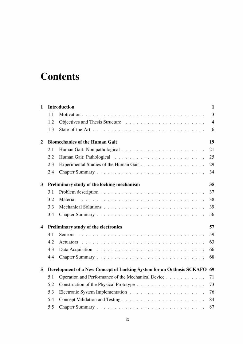
Contents
1 Introduction 11.1 Motivation . . . . . . . . . . . . . . . . . . . . . . . . . . . . . . . . . . 3
1.2 Objectives and Thesis Structure . . . . . . . . . . . . . . . . . . . . . . 4
1.3 State-of-the-Art . . . . . . . . . . . . . . . . . . . . . . . . . . . . . . . 6
2 Biomechanics of the Human Gait 192.1 Human Gait: Non pathological . . . . . . . . . . . . . . . . . . . . . . . 21
2.2 Human Gait: Pathological . . . . . . . . . . . . . . . . . . . . . . . . . 25
2.3 Experimental Studies of the Human Gait . . . . . . . . . . . . . . . . . . 29
2.4 Chapter Summary . . . . . . . . . . . . . . . . . . . . . . . . . . . . . . 34
3 Preliminary study of the locking mechanism 353.1 Problem description . . . . . . . . . . . . . . . . . . . . . . . . . . . . . 37
3.2 Material . . . . . . . . . . . . . . . . . . . . . . . . . . . . . . . . . . . 38
3.3 Mechanical Solutions . . . . . . . . . . . . . . . . . . . . . . . . . . . . 39
3.4 Chapter Summary . . . . . . . . . . . . . . . . . . . . . . . . . . . . . . 56
4 Preliminary study of the electronics 574.1 Sensors . . . . . . . . . . . . . . . . . . . . . . . . . . . . . . . . . . . 59
4.2 Actuators . . . . . . . . . . . . . . . . . . . . . . . . . . . . . . . . . . 63
4.3 Data Acquisition . . . . . . . . . . . . . . . . . . . . . . . . . . . . . . 66
4.4 Chapter Summary . . . . . . . . . . . . . . . . . . . . . . . . . . . . . . 68
5 Development of a New Concept of Locking System for an Orthosis SCKAFO 695.1 Operation and Performance of the Mechanical Device . . . . . . . . . . . 71
5.2 Construction of the Physical Prototype . . . . . . . . . . . . . . . . . . . 73
5.3 Electronic System Implementation . . . . . . . . . . . . . . . . . . . . . 76
5.4 Concept Validation and Testing . . . . . . . . . . . . . . . . . . . . . . . 84
5.5 Chapter Summary . . . . . . . . . . . . . . . . . . . . . . . . . . . . . . 87
ix
CONTENTS
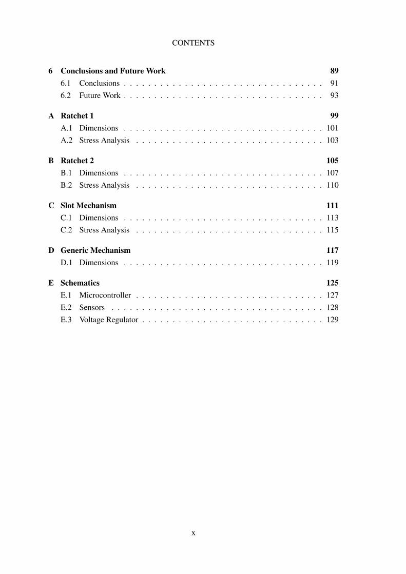
6 Conclusions and Future Work 896.1 Conclusions . . . . . . . . . . . . . . . . . . . . . . . . . . . . . . . . . 916.2 Future Work . . . . . . . . . . . . . . . . . . . . . . . . . . . . . . . . . 93
A Ratchet 1 99A.1 Dimensions . . . . . . . . . . . . . . . . . . . . . . . . . . . . . . . . . 101A.2 Stress Analysis . . . . . . . . . . . . . . . . . . . . . . . . . . . . . . . 103
B Ratchet 2 105B.1 Dimensions . . . . . . . . . . . . . . . . . . . . . . . . . . . . . . . . . 107B.2 Stress Analysis . . . . . . . . . . . . . . . . . . . . . . . . . . . . . . . 110
C Slot Mechanism 111C.1 Dimensions . . . . . . . . . . . . . . . . . . . . . . . . . . . . . . . . . 113C.2 Stress Analysis . . . . . . . . . . . . . . . . . . . . . . . . . . . . . . . 115
D Generic Mechanism 117D.1 Dimensions . . . . . . . . . . . . . . . . . . . . . . . . . . . . . . . . . 119
E Schematics 125E.1 Microcontroller . . . . . . . . . . . . . . . . . . . . . . . . . . . . . . . 127E.2 Sensors . . . . . . . . . . . . . . . . . . . . . . . . . . . . . . . . . . . 128E.3 Voltage Regulator . . . . . . . . . . . . . . . . . . . . . . . . . . . . . . 129
x
List of Figures
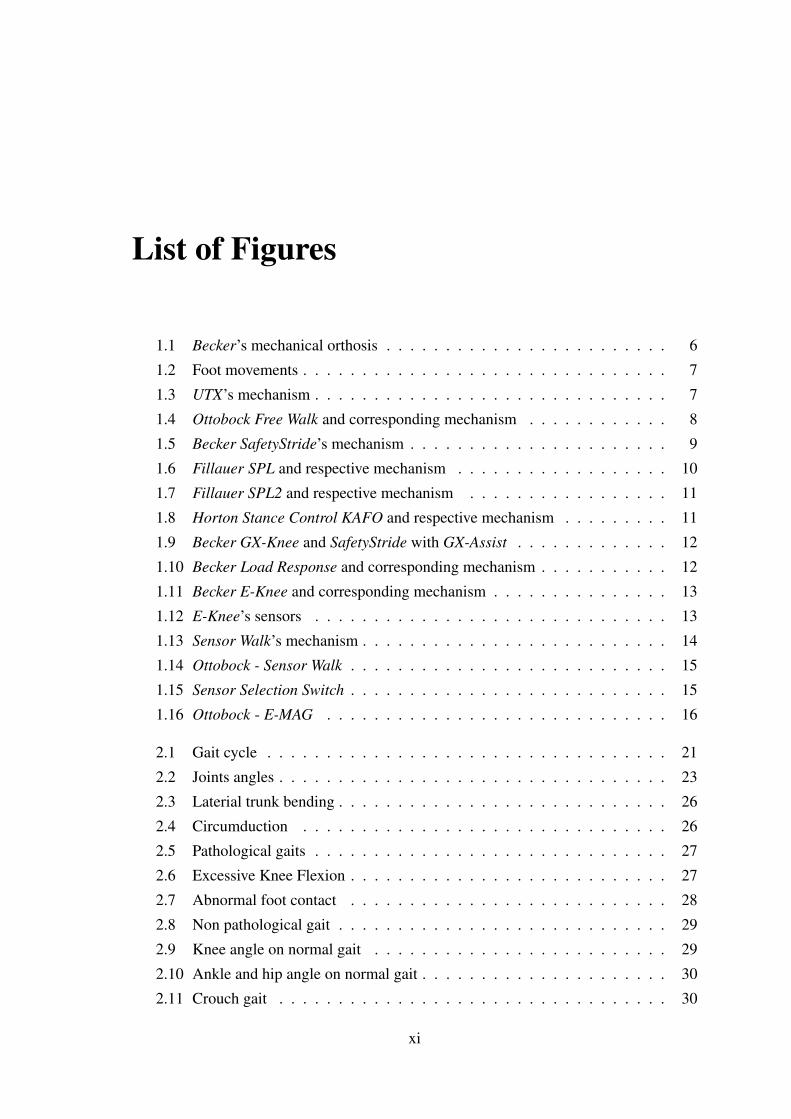
1.1 Becker’s mechanical orthosis . . . . . . . . . . . . . . . . . . . . . . . . 6
1.2 Foot movements . . . . . . . . . . . . . . . . . . . . . . . . . . . . . . . 7
1.3 UTX’s mechanism . . . . . . . . . . . . . . . . . . . . . . . . . . . . . . 7
1.4 Ottobock Free Walk and corresponding mechanism . . . . . . . . . . . . 8
1.5 Becker SafetyStride’s mechanism . . . . . . . . . . . . . . . . . . . . . . 9
1.6 Fillauer SPL and respective mechanism . . . . . . . . . . . . . . . . . . 10
1.7 Fillauer SPL2 and respective mechanism . . . . . . . . . . . . . . . . . 11
1.8 Horton Stance Control KAFO and respective mechanism . . . . . . . . . 11
1.9 Becker GX-Knee and SafetyStride with GX-Assist . . . . . . . . . . . . . 12
1.10 Becker Load Response and corresponding mechanism . . . . . . . . . . . 12
1.11 Becker E-Knee and corresponding mechanism . . . . . . . . . . . . . . . 13
1.12 E-Knee’s sensors . . . . . . . . . . . . . . . . . . . . . . . . . . . . . . 13
1.13 Sensor Walk’s mechanism . . . . . . . . . . . . . . . . . . . . . . . . . . 14
1.14 Ottobock - Sensor Walk . . . . . . . . . . . . . . . . . . . . . . . . . . . 15
1.15 Sensor Selection Switch . . . . . . . . . . . . . . . . . . . . . . . . . . . 15
1.16 Ottobock - E-MAG . . . . . . . . . . . . . . . . . . . . . . . . . . . . . 16
2.1 Gait cycle . . . . . . . . . . . . . . . . . . . . . . . . . . . . . . . . . . 21
2.2 Joints angles . . . . . . . . . . . . . . . . . . . . . . . . . . . . . . . . . 23
2.3 Laterial trunk bending . . . . . . . . . . . . . . . . . . . . . . . . . . . . 26
2.4 Circumduction . . . . . . . . . . . . . . . . . . . . . . . . . . . . . . . 26
2.5 Pathological gaits . . . . . . . . . . . . . . . . . . . . . . . . . . . . . . 27
2.6 Excessive Knee Flexion . . . . . . . . . . . . . . . . . . . . . . . . . . . 27
2.7 Abnormal foot contact . . . . . . . . . . . . . . . . . . . . . . . . . . . 28
2.8 Non pathological gait . . . . . . . . . . . . . . . . . . . . . . . . . . . . 29
2.9 Knee angle on normal gait . . . . . . . . . . . . . . . . . . . . . . . . . 29
2.10 Ankle and hip angle on normal gait . . . . . . . . . . . . . . . . . . . . . 30
2.11 Crouch gait . . . . . . . . . . . . . . . . . . . . . . . . . . . . . . . . . 30
xi
LIST OF FIGURES
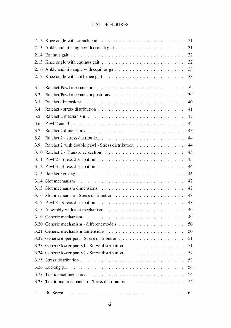
2.12 Knee angle with crouch gait . . . . . . . . . . . . . . . . . . . . . . . . 31
2.13 Ankle and hip angle with crouch gait . . . . . . . . . . . . . . . . . . . . 31
2.14 Equinus gait . . . . . . . . . . . . . . . . . . . . . . . . . . . . . . . . . 32
2.15 Knee angle with equinus gait . . . . . . . . . . . . . . . . . . . . . . . . 32
2.16 Ankle and hip angle with equinus gait . . . . . . . . . . . . . . . . . . . 33
2.17 Knee angle with stiff knee gait . . . . . . . . . . . . . . . . . . . . . . . 33
3.1 Ratchet/Pawl mechanism . . . . . . . . . . . . . . . . . . . . . . . . . . 39
3.2 Ratchet/Pawl mechanism positions . . . . . . . . . . . . . . . . . . . . . 39
3.3 Ratchet dimensions . . . . . . . . . . . . . . . . . . . . . . . . . . . . . 40
3.4 Ratchet - stress distribution . . . . . . . . . . . . . . . . . . . . . . . . . 41
3.5 Ratchet 2 mechanism . . . . . . . . . . . . . . . . . . . . . . . . . . . . 42
3.6 Pawl 2 and 3 . . . . . . . . . . . . . . . . . . . . . . . . . . . . . . . . . 42
3.7 Ratchet 2 dimensions . . . . . . . . . . . . . . . . . . . . . . . . . . . . 43
3.8 Ratchet 2 - stress distribution . . . . . . . . . . . . . . . . . . . . . . . . 44
3.9 Ratchet 2 with double pawl - Stress distribution . . . . . . . . . . . . . . 44
3.10 Ratchet 2 - Transverse section . . . . . . . . . . . . . . . . . . . . . . . 45
3.11 Pawl 2 - Stress distribution . . . . . . . . . . . . . . . . . . . . . . . . . 45
3.12 Pawl 3 - Stress distribution . . . . . . . . . . . . . . . . . . . . . . . . . 46
3.13 Ratchet housing . . . . . . . . . . . . . . . . . . . . . . . . . . . . . . . 46
3.14 Slot mechanism . . . . . . . . . . . . . . . . . . . . . . . . . . . . . . . 47
3.15 Slot mechanism dimensions . . . . . . . . . . . . . . . . . . . . . . . . 47
3.16 Slot mechanism - Stress distribution . . . . . . . . . . . . . . . . . . . . 48
3.17 Pawl 3 - Stress distribution . . . . . . . . . . . . . . . . . . . . . . . . . 48
3.18 Assembly with slot mechanism . . . . . . . . . . . . . . . . . . . . . . . 49
3.19 Generic mechanism . . . . . . . . . . . . . . . . . . . . . . . . . . . . . 49
3.20 Generic mechanism - different models . . . . . . . . . . . . . . . . . . . 50
3.21 Generic mechanism dimensions . . . . . . . . . . . . . . . . . . . . . . 50
3.22 Generic upper part - Stress distribution . . . . . . . . . . . . . . . . . . . 51
3.23 Generic lower part v1 - Stress distribution . . . . . . . . . . . . . . . . . 51
3.24 Generic lower part v2 - Stress distribution . . . . . . . . . . . . . . . . . 52
3.25 Stress distribution . . . . . . . . . . . . . . . . . . . . . . . . . . . . . . 53
3.26 Locking pin . . . . . . . . . . . . . . . . . . . . . . . . . . . . . . . . . 54
3.27 Tradicional mechanism . . . . . . . . . . . . . . . . . . . . . . . . . . . 54
3.28 Traditional mechanism - Stress distribution . . . . . . . . . . . . . . . . 55
4.1 RC Servo . . . . . . . . . . . . . . . . . . . . . . . . . . . . . . . . . . 64
xii
LIST OF FIGURES
4.2 RC Servo control . . . . . . . . . . . . . . . . . . . . . . . . . . . . . . 64
4.3 ATmega128RFA1 . . . . . . . . . . . . . . . . . . . . . . . . . . . . . . 66
4.4 General view of the software . . . . . . . . . . . . . . . . . . . . . . . . 67
5.1 Generic mechanism - v1 . . . . . . . . . . . . . . . . . . . . . . . . . . 71
5.2 Switching operation . . . . . . . . . . . . . . . . . . . . . . . . . . . . . 71
5.3 Sensor measurement . . . . . . . . . . . . . . . . . . . . . . . . . . . . 72
5.4 Built mechanism . . . . . . . . . . . . . . . . . . . . . . . . . . . . . . 73
5.5 Elements of part one . . . . . . . . . . . . . . . . . . . . . . . . . . . . 73
5.6 Elements of part two . . . . . . . . . . . . . . . . . . . . . . . . . . . . 74
5.7 Measured values . . . . . . . . . . . . . . . . . . . . . . . . . . . . . . 74
5.8 Shaft . . . . . . . . . . . . . . . . . . . . . . . . . . . . . . . . . . . . . 75
5.9 KAFO with the built mechanism . . . . . . . . . . . . . . . . . . . . . . 75
5.10 iSensor Inclinometer/Accelerometer Evaluation Board . . . . . . . . . . 76
5.11 CMR3000 - Necessary components . . . . . . . . . . . . . . . . . . . . 77
5.12 PCB with sensors . . . . . . . . . . . . . . . . . . . . . . . . . . . . . . 78
5.13 ATmega128RFA1 schematic . . . . . . . . . . . . . . . . . . . . . . . . 79
5.14 ATmega128RFA1 Board - communication by wire . . . . . . . . . . . . 80
5.15 ATmega128RFA1 Board - wireless communication . . . . . . . . . . . . 80
5.16 Voltage regulator . . . . . . . . . . . . . . . . . . . . . . . . . . . . . . 81
5.17 Built sensor board . . . . . . . . . . . . . . . . . . . . . . . . . . . . . . 82
5.18 Built microcontroller board . . . . . . . . . . . . . . . . . . . . . . . . . 82
5.19 Installed boards . . . . . . . . . . . . . . . . . . . . . . . . . . . . . . . 83
5.20 Installed microcontroller board . . . . . . . . . . . . . . . . . . . . . . . 83
5.21 Unstable mechanism . . . . . . . . . . . . . . . . . . . . . . . . . . . . 84
5.22 Broken wiring . . . . . . . . . . . . . . . . . . . . . . . . . . . . . . . . 85
5.23 Connecting between the microcontroller and the sensors . . . . . . . . . 85
5.24 Batteries voltage . . . . . . . . . . . . . . . . . . . . . . . . . . . . . . 86
5.25 Voltage in the microcontroller . . . . . . . . . . . . . . . . . . . . . . . 86
A.1 Ratchet 1 . . . . . . . . . . . . . . . . . . . . . . . . . . . . . . . . . . 101
A.2 Pawl 1 . . . . . . . . . . . . . . . . . . . . . . . . . . . . . . . . . . . . 102
A.3 Reaction Force and Moment on Constraints . . . . . . . . . . . . . . . . 103
A.4 Result Summary . . . . . . . . . . . . . . . . . . . . . . . . . . . . . . . 103
B.1 Ratchet 2 . . . . . . . . . . . . . . . . . . . . . . . . . . . . . . . . . . 107
B.2 Pawl 2 . . . . . . . . . . . . . . . . . . . . . . . . . . . . . . . . . . . . 108
B.3 Pawl 3 . . . . . . . . . . . . . . . . . . . . . . . . . . . . . . . . . . . . 109
xiii
LIST OF FIGURES
B.4 Reaction Force and Moment on Constraints . . . . . . . . . . . . . . . . 110B.5 Result Summary . . . . . . . . . . . . . . . . . . . . . . . . . . . . . . . 110
C.1 Slot mechanism . . . . . . . . . . . . . . . . . . . . . . . . . . . . . . . 113C.2 Pawl 3 . . . . . . . . . . . . . . . . . . . . . . . . . . . . . . . . . . . . 114C.3 Reaction Force and Moment on Constraints . . . . . . . . . . . . . . . . 115C.4 Result Summary . . . . . . . . . . . . . . . . . . . . . . . . . . . . . . . 115
D.1 Upper mechanism . . . . . . . . . . . . . . . . . . . . . . . . . . . . . . 119D.2 Lower mechanism - v1 . . . . . . . . . . . . . . . . . . . . . . . . . . . 120D.3 Lower mechanism - v2 . . . . . . . . . . . . . . . . . . . . . . . . . . . 121D.4 Lower mechanism - v3 . . . . . . . . . . . . . . . . . . . . . . . . . . . 122D.5 Lower mechanism - v4 . . . . . . . . . . . . . . . . . . . . . . . . . . . 123
E.1 ATmega128RFA1 Board - communication by wire . . . . . . . . . . . . 127E.2 PCB with sensors . . . . . . . . . . . . . . . . . . . . . . . . . . . . . . 128E.3 Voltage regulator LP2985 . . . . . . . . . . . . . . . . . . . . . . . . . . 129
xiv
List of Tables
2.1 Gait cycle timing: Female . . . . . . . . . . . . . . . . . . . . . . . . . 222.2 Gait cycle timing: Male . . . . . . . . . . . . . . . . . . . . . . . . . . . 23
3.1 Stainless Steel 304 composition . . . . . . . . . . . . . . . . . . . . . . 383.2 Stainless Steel 304 characteristics . . . . . . . . . . . . . . . . . . . . . 38
4.1 Accelerometers - Analog Devices . . . . . . . . . . . . . . . . . . . . . . 604.2 Accelerometer - Bosch Sensortec . . . . . . . . . . . . . . . . . . . . . . 604.3 Accelerometers - VTI Technologies . . . . . . . . . . . . . . . . . . . . . 614.4 Inclinometers - Analog Devices . . . . . . . . . . . . . . . . . . . . . . . 614.5 Gyroscopes - Analog Devices . . . . . . . . . . . . . . . . . . . . . . . . 624.6 Gyroscopes - VTI Technologies . . . . . . . . . . . . . . . . . . . . . . . 624.7 RC Servos . . . . . . . . . . . . . . . . . . . . . . . . . . . . . . . . . . 654.8 Stepper Motors - Portescap . . . . . . . . . . . . . . . . . . . . . . . . . 65
5.1 Sensor PCB cost . . . . . . . . . . . . . . . . . . . . . . . . . . . . . . 795.2 ATmega128RFA1 PCB cost . . . . . . . . . . . . . . . . . . . . . . . . 81
xv

LIST OF TABLES
xvi
Abbreviations
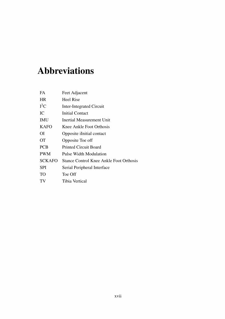
FA Feet AdjacentHR Heel RiseI2C Inter-Integrated CircuitIC Initial ContactIMU Inertial Measurement UnitKAFO Knee Ankle Foot OrthosisOI Opposite iInitial contactOT Opposite Toe offPCB Printed Circuit BoardPWM Pulse Width ModulationSCKAFO Stance Control Knee Ankle Foot OrthosisSPI Serial Peripheral InterfaceTO Toe OffTV Tibia Vertical
xvii


Chapter 1
Introduction
1

Introduction
2
Introduction
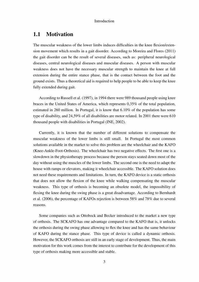
1.1 Motivation
The muscular weakness of the lower limbs induces difficulties in the knee flexion/exten-sion movement which results in a gait disorder. According to Moreira and Flores (2011)the gait disorder can be the result of several diseases, such as: peripheral neurologicaldiseases, central neurological diseases and muscular diseases. A person with muscularweakness does not have the necessary muscular strength to maintain the knee at fullextension during the entire stance phase, that is the contact between the foot and theground exists. Thus a theoretical aid is required to help people to be able to keep the kneefully extended during gait.
According to Russell et al. (1997), in 1994 there were 989 thousand people using kneebraces in the United States of America, which represents 0,35% of the total population,estimated in 260 million. In Portugal, it is know that 6.10% of the population has sometype of disability, and 24,59% of all disabilities are motor related. In 2001 there were 610thousand people with disabilities in Portugal (INE, 2002).
Currently, it is known that the number of different solutions to compensate themuscular weakness of the lower limbs is still small. In Portugal the most commonsolutions available in the market to solve this problem are the wheelchair and the KAFO(Knee-Ankle-Foot-Orthosis). The wheelchair has two negative effects. The first one is aslowdown in the physiotherapy process because the person stays seated down most of theday without using the muscles of the lower limbs. The second one is the need to adapt thehouse with ramps or elevators, making it wheelchair accessible. The KAFO solution doesnot need these requirements and limitations. In turn, the KAFO device is a static orthosisthat does not allow the flexion of the knee while walking compensating the muscularweakness. This type of orthosis is becoming an obsolete model, the impossibility offlexing the knee during the swing phase is a great disadvantage. According to Bernhardtet al. (2006), the percentage of KAFOs rejection is between 58% and 78% due to severalreasons.
Some companies such as Ottobock and Becker introduced to the market a new typeof orthosis. The SCKAFO has one advantage compared to the KAFO that is, it unlocksthe orthosis during the swing phase allowing to flex the knee and has the same behaviourof KAFO during the stance phase. This type of device is called a dynamic orthosis.However, the SCKAFO orthosis are still in an early stage of development. Thus, the mainmotivation for this work comes from the interest to contribute for the development of thistype of orthosis making more accessible and stable.
3
Introduction
1.2 Objectives and Thesis Structure
This work aims to develop a mechatronic locking system for a Stance-Control-Knee-Ankle-Foot-Orthosis (SCKAFO) which will be different from the ones currently avail-able, mainly in what concerns with the need to include fast sensors and cables. With thisapproach also intends to perdict the locking of the mechanism, making available a largerperiod for the locking system to act correctly.
The specific goals of this work can be listed as follows:
• To perform an exhaustive study of the available SCKAFOs;
• To characterize the human gait with and without pathologies;
• To design a new mechanical system for orthosis locking system;
• To develop an electronic system that allows for the control and actuation the orthosislocking system;
• To build a data acquisition in order to access the influence of the developed lockingsystem in the human gait;
• To develop of a functional prototype for verification and validation purpose.
The present dissertation is divided in six main chapters described below.
Chapter one presents the characterization of state of the art in order to evidence thedifferent solutions by the companies with commercial solutions. In addition, a briefdiscussion on this thesis contribution can be found in this chapter.
Chapter two deals with the description of the lower limbs elements, followed bystudies on the non-pathological human gait and pathological gait as well. Specialemphasis is given to both bibliographical and experimental studies.
Chapter three describes the problem to be solved, the limitations and assumptions thatthe locking system must fulfill. Furthermore, in this chapter the proposed mechanicalsolutions and their characteristics are analyzed taking in account the critical points of themechanism and the maximum strength. In this chapter will also be explained the reasonsfor the chosen materials.
4
Introduction
Chapter four shows the electronic parts suitable for this project, such as sensors ormicrocontrollers are discussed. The fundamental reasons to select the components arepresented in this process. The data acquisition software developed is also demonstratedin this chapter.
In Chapter five the new concept of locking mechanism is presented as well as thecorresponding performance. In this chapter the materials, the costs and the process of theconstruction of the physical prototype are discussed. The relation between the electronicsystem and the locking mechanism can also be found in this chapter. Finally, all the testsperformed as well as the concept validation is object of study in this chapter.
The Chapter six contains the issues addressed in the conclusions and the future workare presented.
In Appendices A to D it is possible to see the technical drawings and summary of theresults of stress simulations. In Appendix E is presents the schematics from the developedboards.
5
Introduction
1.3 State-of-the-Art
As result of the technology evolution over the last decades, the quality of the orthosis hasbeen increasing. The use of new versatile and lighter materials improved the functionalityand comfort of the orthosis without compromising the safety of the user. The use of newmaterials also allowed to improve the orthosis aesthetically.
At the end of the 80’s decade and beginning of 90’s decade of last century, the firstSCKAFOs were presented. However with the introduction of electronics, the orthosisgained new capabilities that would not be possible before, because they were purelymechanical devices.
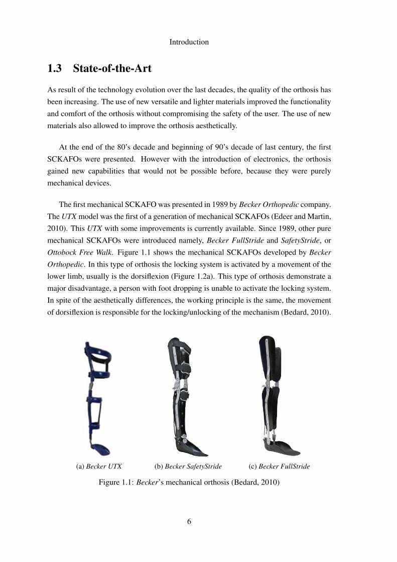
The first mechanical SCKAFO was presented in 1989 by Becker Orthopedic company.The UTX model was the first of a generation of mechanical SCKAFOs (Edeer and Martin,2010). This UTX with some improvements is currently available. Since 1989, other puremechanical SCKAFOs were introduced namely, Becker FullStride and SafetyStride, orOttobock Free Walk. Figure 1.1 shows the mechanical SCKAFOs developed by Becker
Orthopedic. In this type of orthosis the locking system is activated by a movement of thelower limb, usually is the dorsiflexion (Figure 1.2a). This type of orthosis demonstrate amajor disadvantage, a person with foot dropping is unable to activate the locking system.In spite of the aesthetically differences, the working principle is the same, the movementof dorsiflexion is responsible for the locking/unlocking of the mechanism (Bedard, 2010).
(a) Becker UTX (b) Becker SafetyStride (c) Becker FullStride
Figure 1.1: Becker’s mechanical orthosis (Bedard, 2010)
6
Introduction
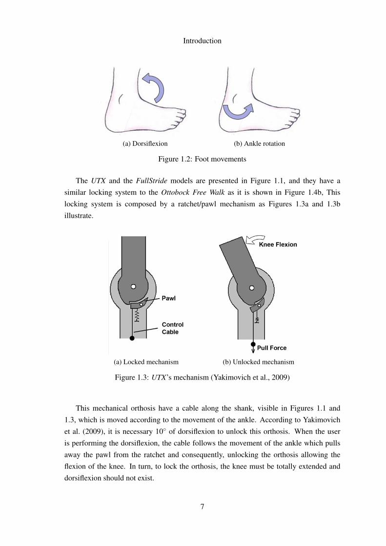
(a) Dorsiflexion (b) Ankle rotation
Figure 1.2: Foot movements
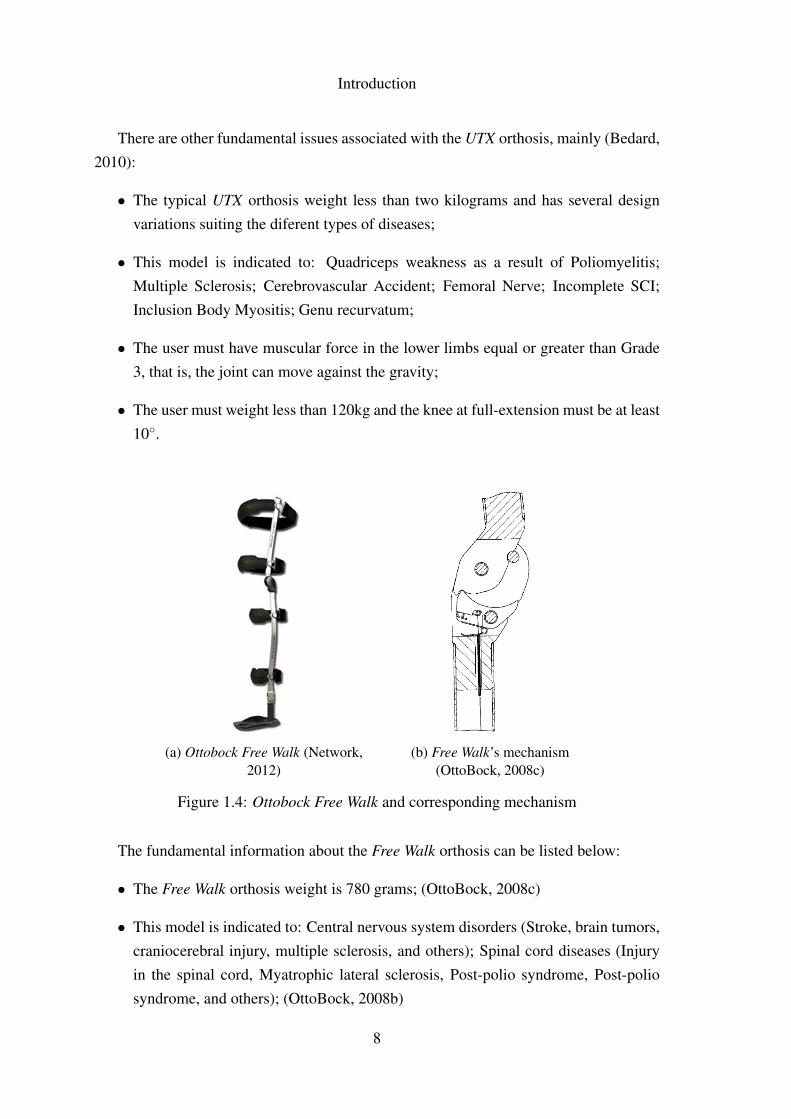
The UTX and the FullStride models are presented in Figure 1.1, and they have asimilar locking system to the Ottobock Free Walk as it is shown in Figure 1.4b, Thislocking system is composed by a ratchet/pawl mechanism as Figures 1.3a and 1.3billustrate.
(a) Locked mechanism (b) Unlocked mechanism
Figure 1.3: UTX’s mechanism (Yakimovich et al., 2009)
This mechanical orthosis have a cable along the shank, visible in Figures 1.1 and1.3, which is moved according to the movement of the ankle. According to Yakimovichet al. (2009), it is necessary 10◦ of dorsiflexion to unlock this orthosis. When the useris performing the dorsiflexion, the cable follows the movement of the ankle which pullsaway the pawl from the ratchet and consequently, unlocking the orthosis allowing theflexion of the knee. In turn, to lock the orthosis, the knee must be totally extended anddorsiflexion should not exist.
7
Introduction
There are other fundamental issues associated with the UTX orthosis, mainly (Bedard,2010):
• The typical UTX orthosis weight less than two kilograms and has several designvariations suiting the diferent types of diseases;
• This model is indicated to: Quadriceps weakness as a result of Poliomyelitis;Multiple Sclerosis; Cerebrovascular Accident; Femoral Nerve; Incomplete SCI;Inclusion Body Myositis; Genu recurvatum;
• The user must have muscular force in the lower limbs equal or greater than Grade3, that is, the joint can move against the gravity;
• The user must weight less than 120kg and the knee at full-extension must be at least10◦.
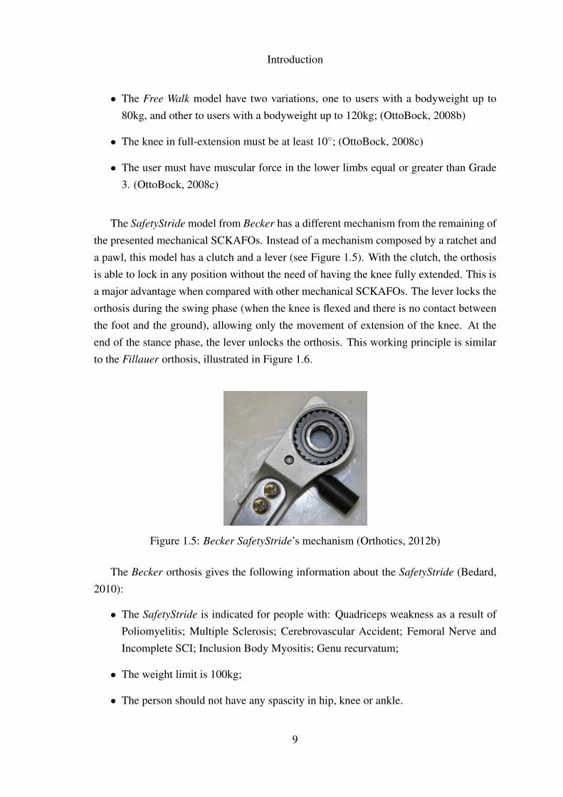
(a) Ottobock Free Walk (Network,2012)
(b) Free Walk’s mechanism(OttoBock, 2008c)
Figure 1.4: Ottobock Free Walk and corresponding mechanism
The fundamental information about the Free Walk orthosis can be listed below:
• The Free Walk orthosis weight is 780 grams; (OttoBock, 2008c)
• This model is indicated to: Central nervous system disorders (Stroke, brain tumors,craniocerebral injury, multiple sclerosis, and others); Spinal cord diseases (Injuryin the spinal cord, Myatrophic lateral sclerosis, Post-polio syndrome, Post-poliosyndrome, and others); (OttoBock, 2008b)
8
Introduction
• The Free Walk model have two variations, one to users with a bodyweight up to80kg, and other to users with a bodyweight up to 120kg; (OttoBock, 2008b)
• The knee in full-extension must be at least 10◦; (OttoBock, 2008c)
• The user must have muscular force in the lower limbs equal or greater than Grade3. (OttoBock, 2008c)
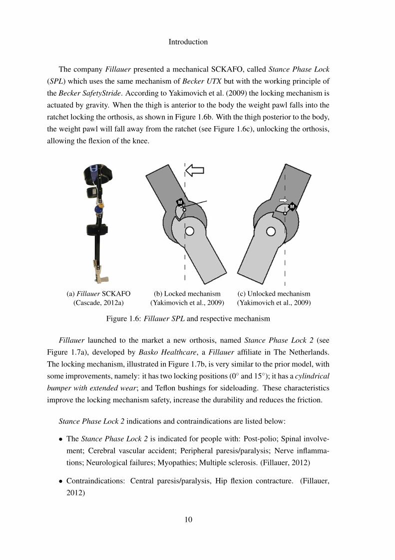
The SafetyStride model from Becker has a different mechanism from the remaining ofthe presented mechanical SCKAFOs. Instead of a mechanism composed by a ratchet anda pawl, this model has a clutch and a lever (see Figure 1.5). With the clutch, the orthosisis able to lock in any position without the need of having the knee fully extended. This isa major advantage when compared with other mechanical SCKAFOs. The lever locks theorthosis during the swing phase (when the knee is flexed and there is no contact betweenthe foot and the ground), allowing only the movement of extension of the knee. At theend of the stance phase, the lever unlocks the orthosis. This working principle is similarto the Fillauer orthosis, illustrated in Figure 1.6.
Figure 1.5: Becker SafetyStride’s mechanism (Orthotics, 2012b)
The Becker orthosis gives the following information about the SafetyStride (Bedard,2010):
• The SafetyStride is indicated for people with: Quadriceps weakness as a result ofPoliomyelitis; Multiple Sclerosis; Cerebrovascular Accident; Femoral Nerve andIncomplete SCI; Inclusion Body Myositis; Genu recurvatum;
• The weight limit is 100kg;
• The person should not have any spascity in hip, knee or ankle.
9
Introduction
The company Fillauer presented a mechanical SCKAFO, called Stance Phase Lock
(SPL) which uses the same mechanism of Becker UTX but with the working principle ofthe Becker SafetyStride. According to Yakimovich et al. (2009) the locking mechanism isactuated by gravity. When the thigh is anterior to the body the weight pawl falls into theratchet locking the orthosis, as shown in Figure 1.6b. With the thigh posterior to the body,the weight pawl will fall away from the ratchet (see Figure 1.6c), unlocking the orthosis,allowing the flexion of the knee.
(a) Fillauer SCKAFO(Cascade, 2012a)
(b) Locked mechanism(Yakimovich et al., 2009)
(c) Unlocked mechanism(Yakimovich et al., 2009)
Figure 1.6: Fillauer SPL and respective mechanism
Fillauer launched to the market a new orthosis, named Stance Phase Lock 2 (seeFigure 1.7a), developed by Basko Healthcare, a Fillauer affiliate in The Netherlands.The locking mechanism, illustrated in Figure 1.7b, is very similar to the prior model, withsome improvements, namely: it has two locking positions (0◦ and 15◦); it has a cylindrical
bumper with extended wear; and Teflon bushings for sideloading. These characteristicsimprove the locking mechanism safety, increase the durability and reduces the friction.
Stance Phase Lock 2 indications and contraindications are listed below:
• The Stance Phase Lock 2 is indicated for people with: Post-polio; Spinal involve-ment; Cerebral vascular accident; Peripheral paresis/paralysis; Nerve inflamma-tions; Neurological failures; Myopathies; Multiple sclerosis. (Fillauer, 2012)
• Contraindications: Central paresis/paralysis, Hip flexion contracture. (Fillauer,2012)
10
Introduction
(a) Fillauer SCKAFO(Cascade, 2012b)
(b) SPL2 mechanism (Fillauer, 2012)
Figure 1.7: Fillauer SPL2 and respective mechanism
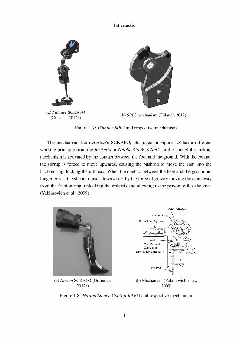
The mechanism from Horton’s SCKAFO, illustrated in Figure 1.8 has a differentworking principle from the Becker’s or Ottobock’s SCKAFO. In this model the lockingmechanism is activated by the contact between the foot and the ground. With the contactthe stirrup is forced to move upwards, causing the pushrod to move the cam into thefriction ring, locking the orthosis. When the contact between the heel and the ground nolonger exists, the stirrup moves downwards by the force of gravity moving the cam awayfrom the friction ring, unlocking the orthosis and allowing to the person to flex the knee(Yakimovich et al., 2009).
(a) Horton SCKAFO (Orthotics,2012a)
(b) Mechanism (Yakimovich et al.,2009)
Figure 1.8: Horton Stance Control KAFO and respective mechanism
11
Introduction
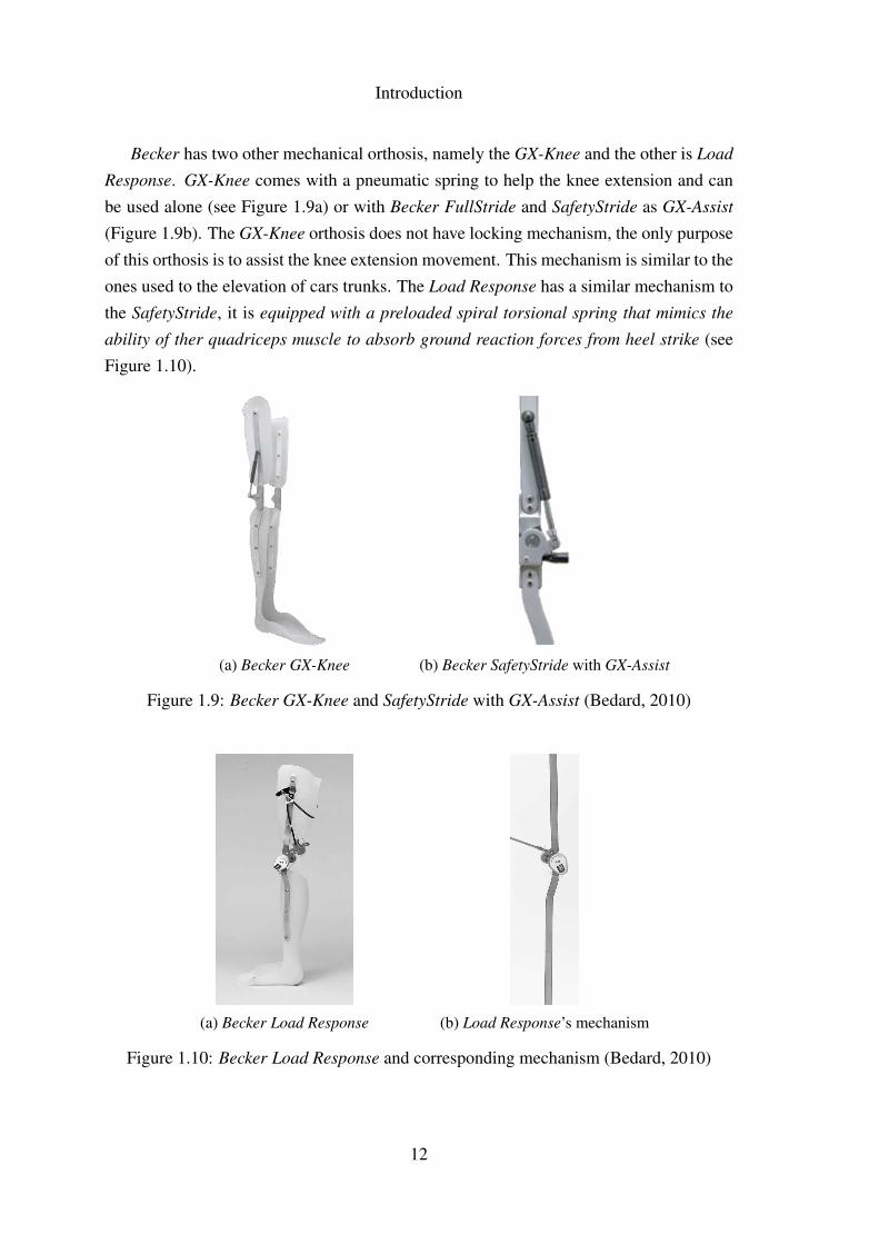
Becker has two other mechanical orthosis, namely the GX-Knee and the other is Load
Response. GX-Knee comes with a pneumatic spring to help the knee extension and canbe used alone (see Figure 1.9a) or with Becker FullStride and SafetyStride as GX-Assist
(Figure 1.9b). The GX-Knee orthosis does not have locking mechanism, the only purposeof this orthosis is to assist the knee extension movement. This mechanism is similar to theones used to the elevation of cars trunks. The Load Response has a similar mechanism tothe SafetyStride, it is equipped with a preloaded spiral torsional spring that mimics the
ability of ther quadriceps muscle to absorb ground reaction forces from heel strike (seeFigure 1.10).
(a) Becker GX-Knee (b) Becker SafetyStride with GX-Assist
Figure 1.9: Becker GX-Knee and SafetyStride with GX-Assist (Bedard, 2010)
(a) Becker Load Response (b) Load Response’s mechanism
Figure 1.10: Becker Load Response and corresponding mechanism (Bedard, 2010)
12
Introduction
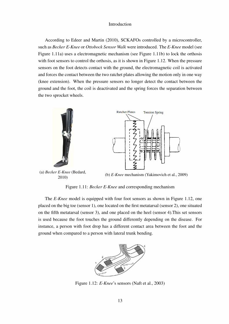
According to Edeer and Martin (2010), SCKAFOs controlled by a microcontroller,such as Becker E-Knee or Ottobock Sensor Walk were introduced. The E-Knee model (seeFigure 1.11a) uses a electromagnetic mechanism (see Figure 1.11b) to lock the orthosiswith foot sensors to control the orthosis, as it is shown in Figure 1.12. When the pressuresensors on the foot detects contact with the ground, the electromagnetic coil is activatedand forces the contact between the two ratchet plates allowing the motion only in one way(knee extension). When the pressure sensors no longer detect the contact between theground and the foot, the coil is deactivated and the spring forces the separation betweenthe two sprocket wheels.
(a) Becker E-Knee (Bedard,2010)
(b) E-Knee mechanism (Yakimovich et al., 2009)
Figure 1.11: Becker E-Knee and corresponding mechanism
The E-Knee model is equipped with four foot sensors as shown in Figure 1.12, oneplaced on the big toe (sensor 1), one located on the first metatarsal (sensor 2), one situatedon the fifth metatarsal (sensor 3), and one placed on the heel (sensor 4).This set sensorsis used because the foot touches the ground differently depending on the disease. Forinstance, a person with foot drop has a different contact area between the foot and theground when compared to a person with lateral trunk bending.
Figure 1.12: E-Knee’s sensors (Naft et al., 2003)
13
Introduction
Becker E-Knee additional features, namely:
• The Becker E-Knee is indicated to people with: Quadriceps weakness as a resultof Poliomyelitis; Multiple Sclerosis; Cerebral vascular Accident; Femoral Nerve;Incomplete SCI; Inclusion Body Myositis (Bedard, 2010);
• Contraindications: Users with bodyweight superior to 100kg; Spasticity in hip,knee or ankle; Fixed varus or valgus deformity at the knee superior to 15◦;Substantial leg length discrepancy (Bedard, 2010).
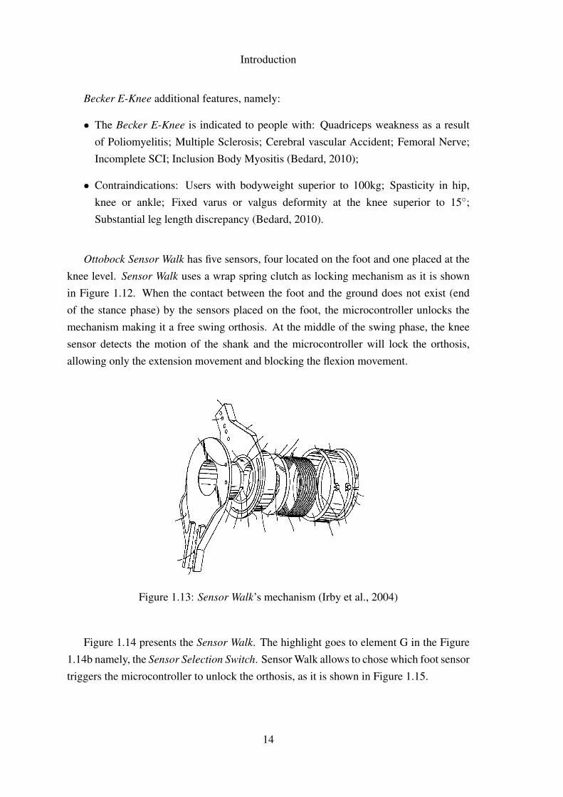
Ottobock Sensor Walk has five sensors, four located on the foot and one placed at theknee level. Sensor Walk uses a wrap spring clutch as locking mechanism as it is shownin Figure 1.12. When the contact between the foot and the ground does not exist (endof the stance phase) by the sensors placed on the foot, the microcontroller unlocks themechanism making it a free swing orthosis. At the middle of the swing phase, the kneesensor detects the motion of the shank and the microcontroller will lock the orthosis,allowing only the extension movement and blocking the flexion movement.
Figure 1.13: Sensor Walk’s mechanism (Irby et al., 2004)
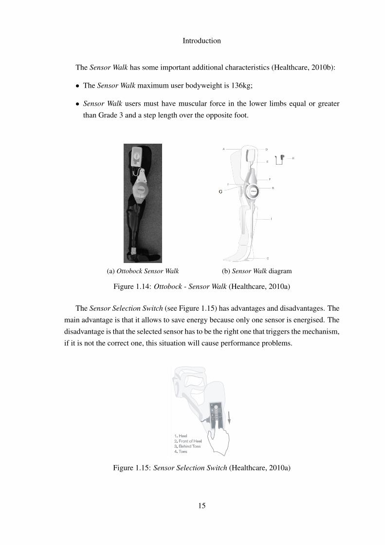
Figure 1.14 presents the Sensor Walk. The highlight goes to element G in the Figure1.14b namely, the Sensor Selection Switch. Sensor Walk allows to chose which foot sensortriggers the microcontroller to unlock the orthosis, as it is shown in Figure 1.15.
14
Introduction
The Sensor Walk has some important additional characteristics (Healthcare, 2010b):
• The Sensor Walk maximum user bodyweight is 136kg;
• Sensor Walk users must have muscular force in the lower limbs equal or greaterthan Grade 3 and a step length over the opposite foot.
(a) Ottobock Sensor Walk (b) Sensor Walk diagram
Figure 1.14: Ottobock - Sensor Walk (Healthcare, 2010a)
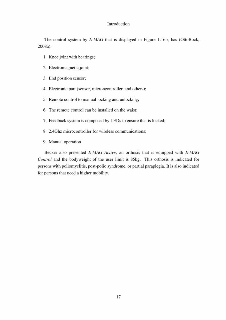
The Sensor Selection Switch (see Figure 1.15) has advantages and disadvantages. Themain advantage is that it allows to save energy because only one sensor is energised. Thedisadvantage is that the selected sensor has to be the right one that triggers the mechanism,if it is not the correct one, this situation will cause performance problems.
Figure 1.15: Sensor Selection Switch (Healthcare, 2010a)
15
Introduction
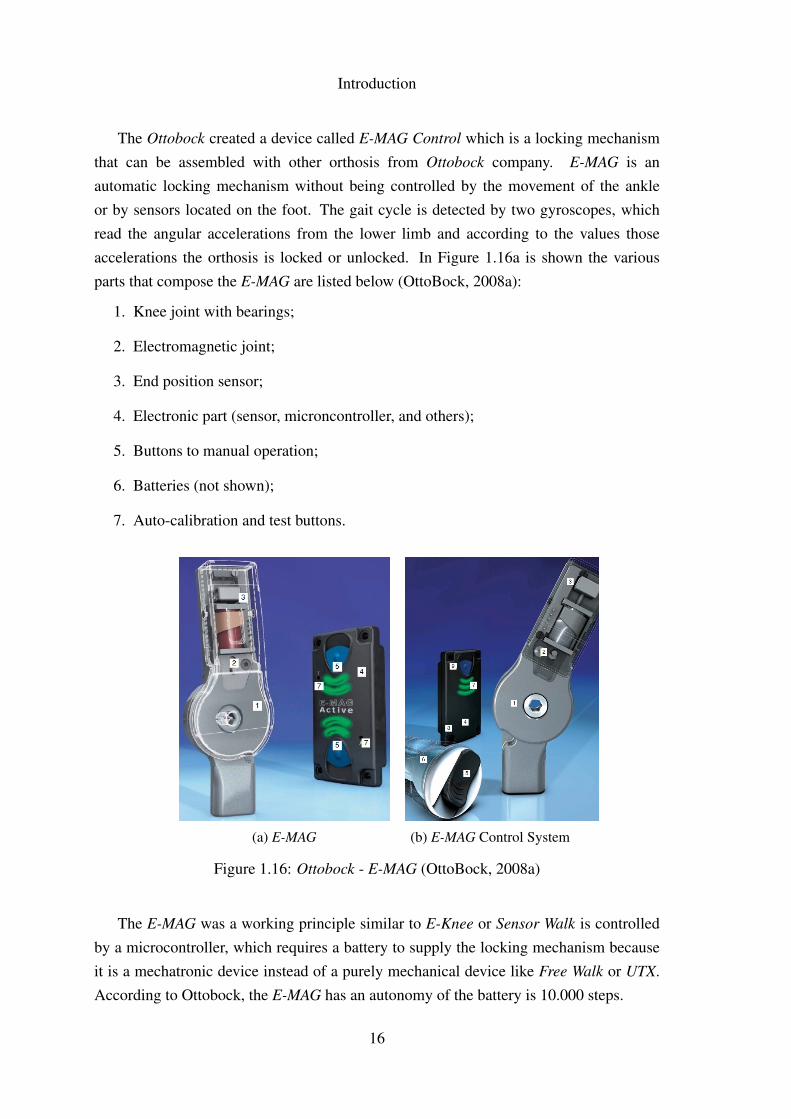
The Ottobock created a device called E-MAG Control which is a locking mechanismthat can be assembled with other orthosis from Ottobock company. E-MAG is anautomatic locking mechanism without being controlled by the movement of the ankleor by sensors located on the foot. The gait cycle is detected by two gyroscopes, whichread the angular accelerations from the lower limb and according to the values thoseaccelerations the orthosis is locked or unlocked. In Figure 1.16a is shown the variousparts that compose the E-MAG are listed below (OttoBock, 2008a):
1. Knee joint with bearings;
2. Electromagnetic joint;
3. End position sensor;
4. Electronic part (sensor, microncontroller, and others);
5. Buttons to manual operation;
6. Batteries (not shown);
7. Auto-calibration and test buttons.
(a) E-MAG (b) E-MAG Control System
Figure 1.16: Ottobock - E-MAG (OttoBock, 2008a)
The E-MAG was a working principle similar to E-Knee or Sensor Walk is controlledby a microcontroller, which requires a battery to supply the locking mechanism becauseit is a mechatronic device instead of a purely mechanical device like Free Walk or UTX.According to Ottobock, the E-MAG has an autonomy of the battery is 10.000 steps.
16
Introduction
The control system by E-MAG that is displayed in Figure 1.16b, has (OttoBock,2008a):
1. Knee joint with bearings;
2. Electromagnetic joint;
3. End position sensor;
4. Electronic part (sensor, microncontroller, and others);
5. Remote control to manual locking and unlocking;
6. The remote control can be installed on the waist;
7. Feedback system is composed by LEDs to ensure that is locked;
8. 2.4Ghz microcontroller for wireless communications;
9. Manual operation
Becker also presented E-MAG Active, an orthosis that is equipped with E-MAG
Control and the bodyweight of the user limit is 85kg. This orthosis is indicated forpersons with poliomyelitis, post-polio syndrome, or partial paraplegia. It is also indicatedfor persons that need a higher mobility.
17

Introduction
18

Chapter 2
Biomechanics of the Human Gait
19

Biomechanics of the Human Gait
20
Biomechanics of the Human Gait
2.1 Human Gait: Non pathological
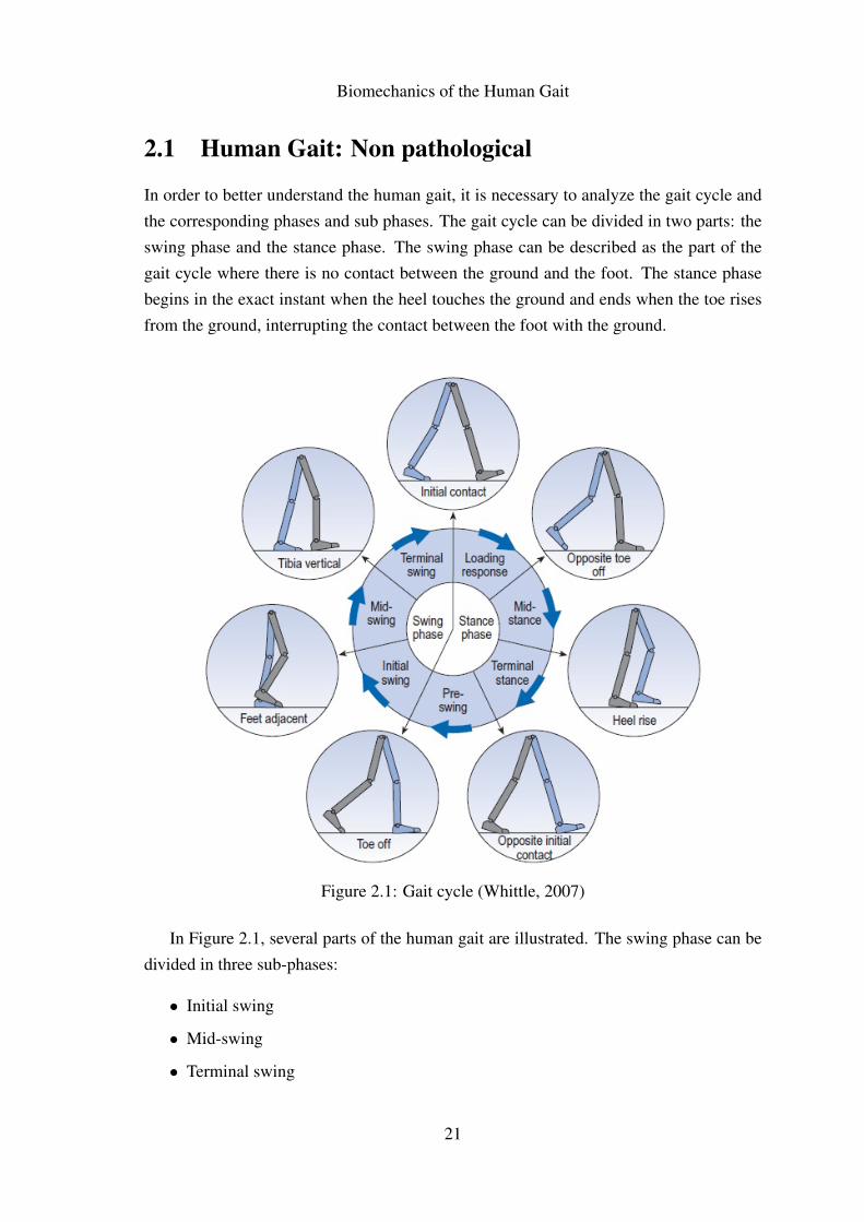
In order to better understand the human gait, it is necessary to analyze the gait cycle andthe corresponding phases and sub phases. The gait cycle can be divided in two parts: theswing phase and the stance phase. The swing phase can be described as the part of thegait cycle where there is no contact between the ground and the foot. The stance phasebegins in the exact instant when the heel touches the ground and ends when the toe risesfrom the ground, interrupting the contact between the foot with the ground.
Figure 2.1: Gait cycle (Whittle, 2007)
In Figure 2.1, several parts of the human gait are illustrated. The swing phase can bedivided in three sub-phases:
• Initial swing
• Mid-swing
• Terminal swing
21
Biomechanics of the Human Gait
The stance phase is divided in four sub-phases:
• Loading response
• Mid-stance
• Terminal stance
• Pre-swing
The sub-phases above described are separated by seven instants as it is shown inFigure 2.1:
• Initial contact (IC);
• Opposite toe off (OT);
• Heel rise (HR);
• Opposite initial contact (OI);
• Toe off (TO);
• Feet adjacent (FA);
• Tibial vertial (TV).
The transition between swing phase and stance phase happens in the instant namedinitial contact, in this situation the point of contact between the ground and the foot istrough the heel. The opposite transition occurs when the instant named toe off initializesthe swing phase.
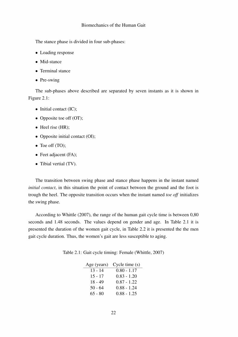
According to Whittle (2007), the range of the human gait cycle time is between 0,80seconds and 1.48 seconds. The values depend on gender and age. In Table 2.1 it ispresented the duration of the women gait cycle, in Table 2.2 it is presented the the mengait cycle duration. Thus, the women’s gait are less susceptible to aging.
Table 2.1: Gait cycle timing: Female (Whittle, 2007)
Age (years) Cycle time (s)13 - 14 0.80 - 1.1715 - 17 0.83 - 1.2018 - 49 0.87 - 1.2250 - 64 0.88 - 1.2465 - 80 0.88 - 1.25
22
Biomechanics of the Human Gait
The women’s minimum gait cycle duration varies from 0,8 seconds (from 13 to 14years) to 0,88 seconds (from 65 to 80 years), 0,08 seconds of difference. The women’smaximum gait cycle time is between 1,17 and 1,25 seconds, the same 0,08 seconds ofdifference. In men’s gait cycle the differences are larger. The minimum gait cycle timeis between 0,81 (from 13 to 14 years) seconds and 0,96 seconds (from 65 to 80 years),0,15 seconds of difference. The men’s maximum gait cycle time goes from 1,20 secondsto 1,48 seconds, 0,28 seconds of difference. This aspects shows that men gait are moreinfluenced by aging.
Table 2.2: Gait cycle timing: Male (Whittle, 2007)
Age (years) Cycle time (s)13 - 14 0.81 - 1.2015 - 17 0.85 - 1.2518 - 49 0.89 - 1.3250 - 64 0.95 - 1.4665 - 80 0.96 - 1.48
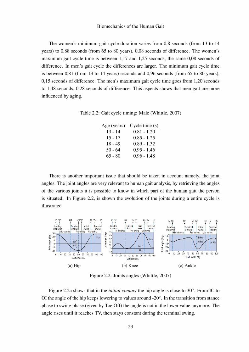
There is another important issue that should be taken in account namely, the jointangles. The joint angles are very relevant to human gait analysis, by retrieving the anglesof the various joints it is possible to know in which part of the human gait the personis situated. In Figure 2.2, is shown the evolution of the joints during a entire cycle isillustrated.
(a) Hip (b) Knee (c) Ankle
Figure 2.2: Joints angles (Whittle, 2007)
Figure 2.2a shows that in the initial contact the hip angle is close to 30◦. From IC toOI the angle of the hip keeps lowering to values around -20◦. In the transition from stancephase to swing phase (given by Toe Off) the angle is not in the lower value anymore. Theangle rises until it reaches TV, then stays constant during the terminal swing.
23

Biomechanics of the Human Gait
Figure 2.2b shows that in the IC the knee is almost fully-extended. After the IC, theknee flexes slightly in the beginning of the stance phase. With lifting of heel the kneestarts to flexing until the maximum value in the initial swing, nearly 50◦, then the kneestarts extending to repeat the gait cycle.
Finally, the ankle (see Figure 2.2c) stays almost in the same position, except thenegative peak in the initial swing, this is moment when the person rises the foot fromthe ground.
24
Biomechanics of the Human Gait
2.2 Human Gait: Pathological
There are several diseases that can affect the normal gait of a human being, thesediseases can be divided into three main groups: central neurological diseases; peripheralneurological diseases; and muscular diseases. The central neurological diseases can besubdivided into six (Moreira and Flores, 2011):
• Multiple sclerosis
• Cerebral palsy
• Parkinson disease
• Brain injury
• Stroke
• Spinal Cord Injury
In turn, the diseases that belong to the peripheral neurological diseases group are asfollows (Moreira and Flores, 2011):
• Poliomyelitis
• Post-polio syndrome
• Spina bifida
• Poly neuropathy
• Stroke
• Spinal Cord Injury
Finally, the muscular diseases can be listed as (Moreira and Flores, 2011):
• Duchenne muscular dystrophy
• Becker’s muscular dystrophy
• Myasthenia gravis
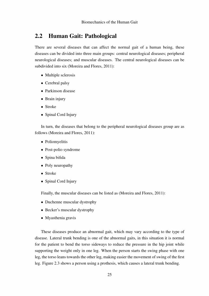
These diseases produce an abnormal gait, which may vary according to the type ofdisease. Lateral trunk bending is one of the abnormal gaits, in this situation it is normalfor the patient to bend the torso sideways to reduce the pressure in the hip joint whilesupporting the weight only in one leg. When the person starts the swing phase with oneleg, the torso leans towards the other leg, making easier the movement of swing of the firstleg. Figure 2.3 shows a person using a prothesis, which causes a lateral trunk bending.
25
Biomechanics of the Human Gait
Figure 2.3: Laterial trunk bending (Craig, 2012)
The common reasons to this abnormal gait are: Painful hip, hip abductor weakness,abnormal hip joint, wide walking base and unequal leg length. There is also anterior andposterior trunk bending, in these cases the torso moves erratically in the sagittal plane.With anterior trunk bending the person flex the torso in the stance phase to compensatethe muscular weakness of the muscles responsible for the movement of knee extension.The posterior trunk bending is the inverse movement of the anterior trunk bending wherethe person moves the torso backwards in order to compensate the muscular weakness ofthe muscles responsible for the movement of hip extension.
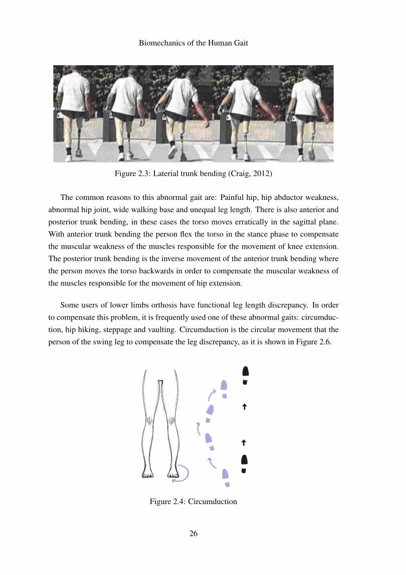
Some users of lower limbs orthosis have functional leg length discrepancy. In orderto compensate this problem, it is frequently used one of these abnormal gaits: circumduc-tion, hip hiking, steppage and vaulting. Circumduction is the circular movement that theperson of the swing leg to compensate the leg discrepancy, as it is shown in Figure 2.6.
Figure 2.4: Circumduction
26
Biomechanics of the Human Gait
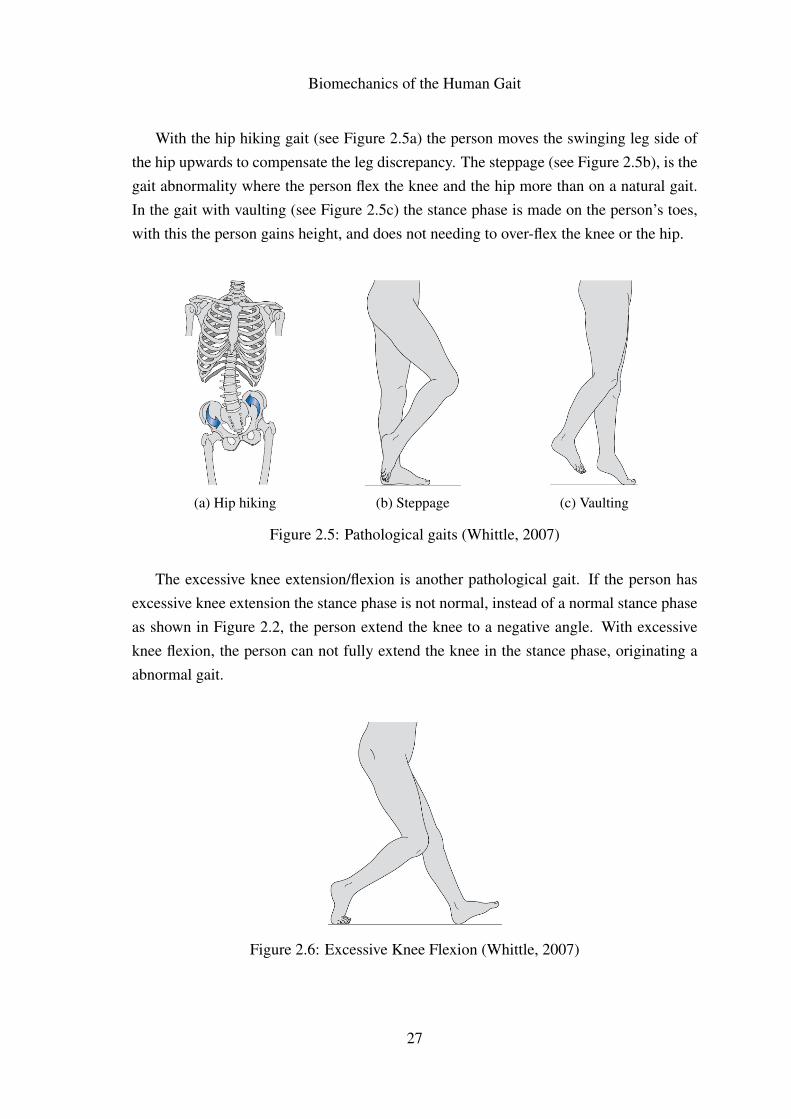
With the hip hiking gait (see Figure 2.5a) the person moves the swinging leg side ofthe hip upwards to compensate the leg discrepancy. The steppage (see Figure 2.5b), is thegait abnormality where the person flex the knee and the hip more than on a natural gait.In the gait with vaulting (see Figure 2.5c) the stance phase is made on the person’s toes,with this the person gains height, and does not needing to over-flex the knee or the hip.
(a) Hip hiking (b) Steppage (c) Vaulting
Figure 2.5: Pathological gaits (Whittle, 2007)
The excessive knee extension/flexion is another pathological gait. If the person hasexcessive knee extension the stance phase is not normal, instead of a normal stance phaseas shown in Figure 2.2, the person extend the knee to a negative angle. With excessiveknee flexion, the person can not fully extend the knee in the stance phase, originating aabnormal gait.
Figure 2.6: Excessive Knee Flexion (Whittle, 2007)
27
Biomechanics of the Human Gait
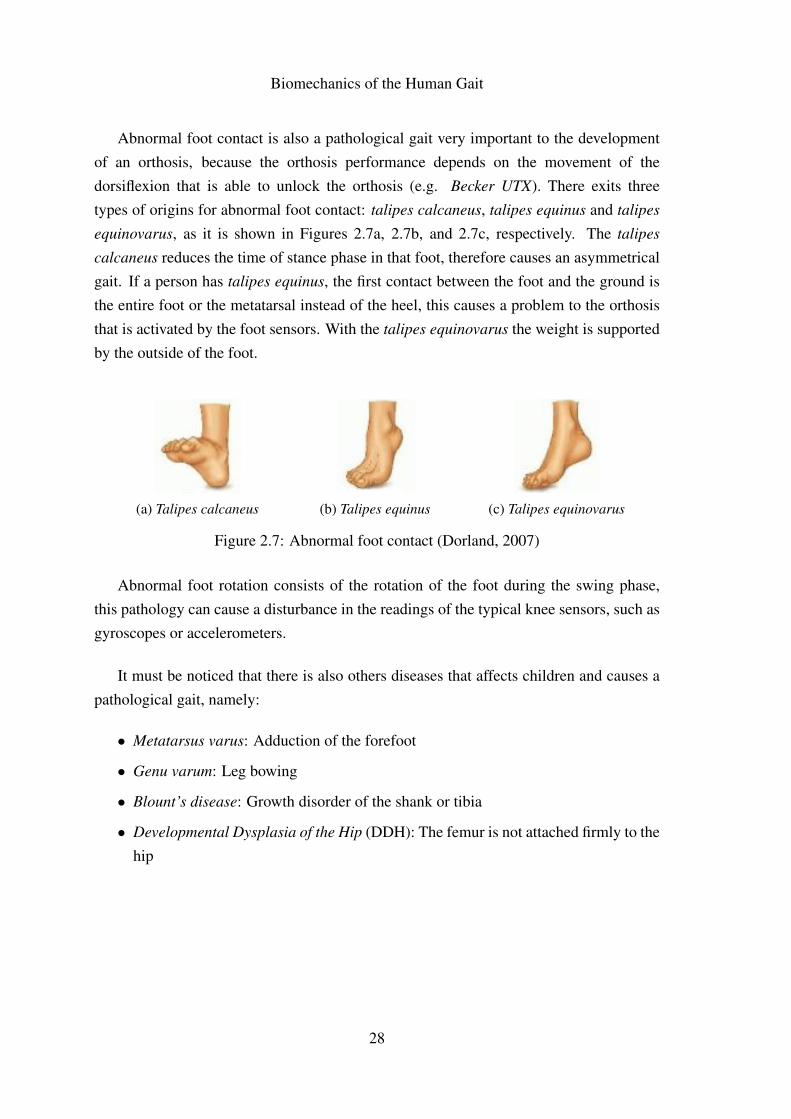
Abnormal foot contact is also a pathological gait very important to the developmentof an orthosis, because the orthosis performance depends on the movement of thedorsiflexion that is able to unlock the orthosis (e.g. Becker UTX). There exits threetypes of origins for abnormal foot contact: talipes calcaneus, talipes equinus and talipes
equinovarus, as it is shown in Figures 2.7a, 2.7b, and 2.7c, respectively. The talipes
calcaneus reduces the time of stance phase in that foot, therefore causes an asymmetricalgait. If a person has talipes equinus, the first contact between the foot and the ground isthe entire foot or the metatarsal instead of the heel, this causes a problem to the orthosisthat is activated by the foot sensors. With the talipes equinovarus the weight is supportedby the outside of the foot.
(a) Talipes calcaneus (b) Talipes equinus (c) Talipes equinovarus
Figure 2.7: Abnormal foot contact (Dorland, 2007)
Abnormal foot rotation consists of the rotation of the foot during the swing phase,this pathology can cause a disturbance in the readings of the typical knee sensors, such asgyroscopes or accelerometers.
It must be noticed that there is also others diseases that affects children and causes apathological gait, namely:
• Metatarsus varus: Adduction of the forefoot
• Genu varum: Leg bowing
• Blount’s disease: Growth disorder of the shank or tibia
• Developmental Dysplasia of the Hip (DDH): The femur is not attached firmly to thehip
28
Biomechanics of the Human Gait
2.3 Experimental Studies of the Human Gait
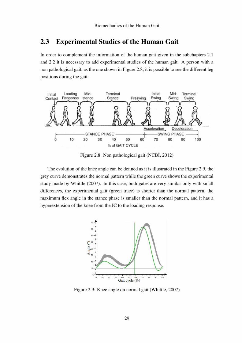
In order to complement the information of the human gait given in the subchapters 2.1and 2.2 it is necessary to add experimental studies of the human gait. A person with anon pathological gait, as the one shown in Figure 2.8, it is possible to see the different legpositions during the gait.
Figure 2.8: Non pathological gait (NCBI, 2012)
The evolution of the knee angle can be defined as it is illustrated in the Figure 2.9, thegrey curve demonstrates the normal pattern while the green curve shows the experimentalstudy made by Whittle (2007). In this case, both gates are very similar only with smalldifferences, the experimental gait (green trace) is shorter than the normal pattern, themaximum flex angle in the stance phase is smaller than the normal pattern, and it has ahyperextension of the knee from the IC to the loading response.
Figure 2.9: Knee angle on normal gait (Whittle, 2007)
29
Biomechanics of the Human Gait
In a normal gait, when the initial contact occurs the knee is fully-extended. During theloading response and mid-stance there is a small flexion of the knee. After the mid-stance(approximately at 40% of the gait cycle) the knee is extended once again until the heelrising. With the heel rising, the knee follows that movement and compensates by flexingthe knee. During the swing phase (from 48% until 90% of the gait cycle) the knee staysflexed, extending only to repeat the initial contact once again.
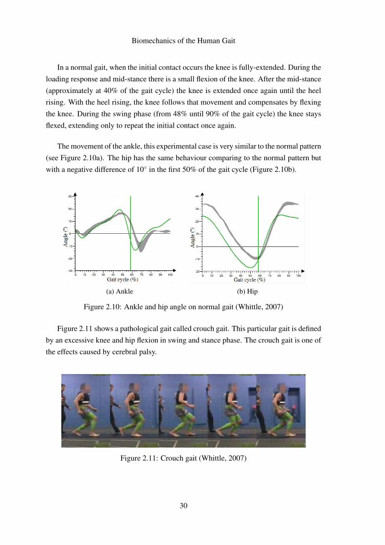
The movement of the ankle, this experimental case is very similar to the normal pattern(see Figure 2.10a). The hip has the same behaviour comparing to the normal pattern butwith a negative difference of 10◦ in the first 50% of the gait cycle (Figure 2.10b).
(a) Ankle (b) Hip
Figure 2.10: Ankle and hip angle on normal gait (Whittle, 2007)
Figure 2.11 shows a pathological gait called crouch gait. This particular gait is definedby an excessive knee and hip flexion in swing and stance phase. The crouch gait is one ofthe effects caused by cerebral palsy.
Figure 2.11: Crouch gait (Whittle, 2007)
30
Biomechanics of the Human Gait
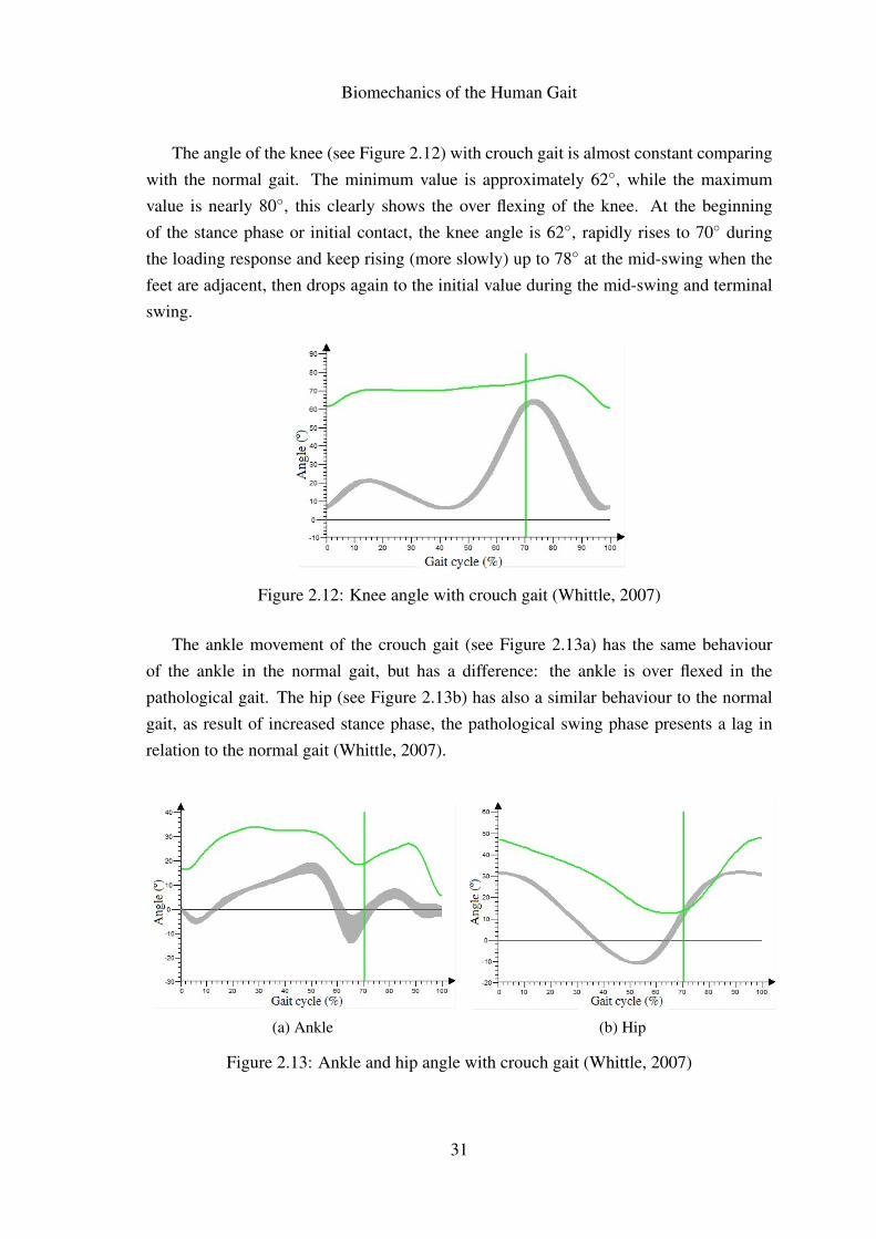
The angle of the knee (see Figure 2.12) with crouch gait is almost constant comparingwith the normal gait. The minimum value is approximately 62◦, while the maximumvalue is nearly 80◦, this clearly shows the over flexing of the knee. At the beginningof the stance phase or initial contact, the knee angle is 62◦, rapidly rises to 70◦ duringthe loading response and keep rising (more slowly) up to 78◦ at the mid-swing when thefeet are adjacent, then drops again to the initial value during the mid-swing and terminalswing.
Figure 2.12: Knee angle with crouch gait (Whittle, 2007)
The ankle movement of the crouch gait (see Figure 2.13a) has the same behaviourof the ankle in the normal gait, but has a difference: the ankle is over flexed in thepathological gait. The hip (see Figure 2.13b) has also a similar behaviour to the normalgait, as result of increased stance phase, the pathological swing phase presents a lag inrelation to the normal gait (Whittle, 2007).
(a) Ankle (b) Hip
Figure 2.13: Ankle and hip angle with crouch gait (Whittle, 2007)
31
Biomechanics of the Human Gait
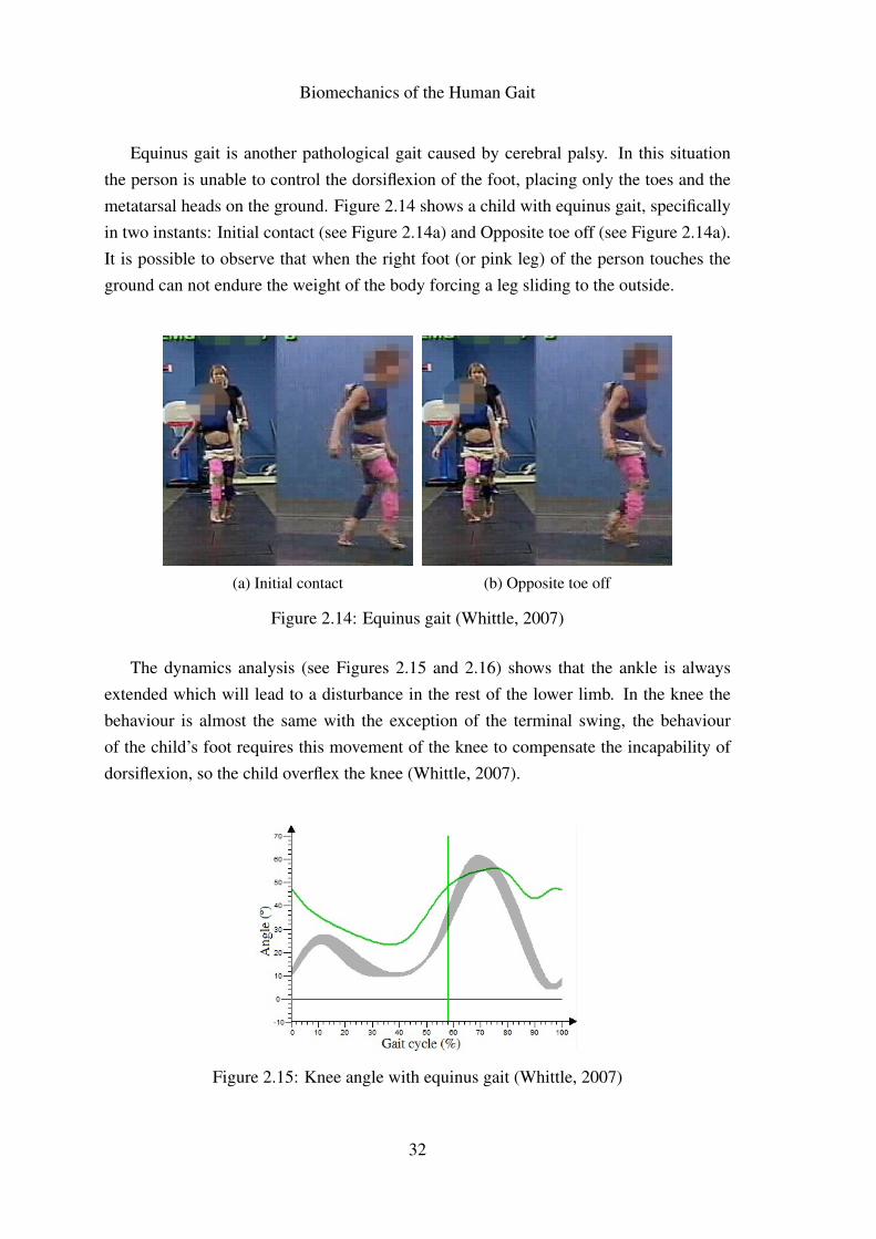
Equinus gait is another pathological gait caused by cerebral palsy. In this situationthe person is unable to control the dorsiflexion of the foot, placing only the toes and themetatarsal heads on the ground. Figure 2.14 shows a child with equinus gait, specificallyin two instants: Initial contact (see Figure 2.14a) and Opposite toe off (see Figure 2.14a).It is possible to observe that when the right foot (or pink leg) of the person touches theground can not endure the weight of the body forcing a leg sliding to the outside.
(a) Initial contact (b) Opposite toe off
Figure 2.14: Equinus gait (Whittle, 2007)
The dynamics analysis (see Figures 2.15 and 2.16) shows that the ankle is alwaysextended which will lead to a disturbance in the rest of the lower limb. In the knee thebehaviour is almost the same with the exception of the terminal swing, the behaviourof the child’s foot requires this movement of the knee to compensate the incapability ofdorsiflexion, so the child overflex the knee (Whittle, 2007).
Figure 2.15: Knee angle with equinus gait (Whittle, 2007)
32
Biomechanics of the Human Gait
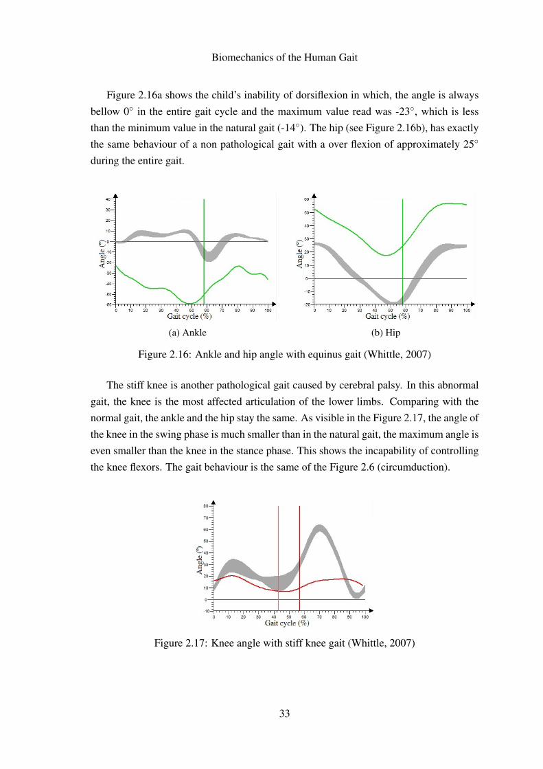
Figure 2.16a shows the child’s inability of dorsiflexion in which, the angle is alwaysbellow 0◦ in the entire gait cycle and the maximum value read was -23◦, which is lessthan the minimum value in the natural gait (-14◦). The hip (see Figure 2.16b), has exactlythe same behaviour of a non pathological gait with a over flexion of approximately 25◦
during the entire gait.
(a) Ankle (b) Hip
Figure 2.16: Ankle and hip angle with equinus gait (Whittle, 2007)
The stiff knee is another pathological gait caused by cerebral palsy. In this abnormalgait, the knee is the most affected articulation of the lower limbs. Comparing with thenormal gait, the ankle and the hip stay the same. As visible in the Figure 2.17, the angle ofthe knee in the swing phase is much smaller than in the natural gait, the maximum angle iseven smaller than the knee in the stance phase. This shows the incapability of controllingthe knee flexors. The gait behaviour is the same of the Figure 2.6 (circumduction).
Figure 2.17: Knee angle with stiff knee gait (Whittle, 2007)
33
Biomechanics of the Human Gait
2.4 Chapter Summary
In this chapter a lower limb description was presented and the pathologies that affectsthem were also described. The human gait includes two main phases: stance phase andswing phase. In turn, these two phase can be subdivided into seven parts, these parts aredevided by seven movements that defines the end of one part and sets the beginning of thenext. The gait cycle times through the different ages and genders was also discussed.
The three main type of diseases were discussed. A list of the central neurologicaldiseases, peripheral neurological diseases and muscular diseases were made, also can befound how these diseases affects the human gait.
Experimental studies performed by some authors were discussed in this chapter witha comparison to the normal pattern and to the theoretical data. These studies include theresults of some diseases in the articulations and how it is possible to identify the diseasesat naked eye according to the gait.
34
Chapter 3
Preliminary study of the lockingmechanism
35
Preliminary study of the locking mechanism
36
Preliminary study of the locking mechanism
3.1 Problem description
The main goals when designing a functional SCKAFO are: allowing knee flexion duringthe swing phase and immobilizing it during the stance phase. According to Moreira et al.(2011) and Yakimovich et al. (2006b) a SCKAFO must accomplish several requirementsin addition to the main goals:
• To switching between phases in less than 6ms;
• To switch from lock to unlock without requiring a fully-extended knee;
• To be silent or at least the most quiet possible;
• To allow knee extension at anytime and knee flexion movement up to 110◦ in orderto allow the user to climb stairs and sit;
• To be as light as possible, preferably with a weight less than 2kg;
• In cosmetic terms, the orthosis should be discrete and should be appealing to theuser, this reduces the chances of late rejection;
• The knee joint mechanism should not have more than 2cm of thickness;
• The orthosis should resist to a moment of 77Nm (90kg user);
• Resist to fatigue and have a mean-time of six months between the maintenance.
In resume the orthosis should be light, noiseless, durable and with a fast reaction time.
The knee joint mechanism should be produced from a material of high hardnessthat allows to withstand the forces to which the mechanism is subjected. This typeof mechanism is made of metallic materials, such as steel. Usually these type ofmechanisms are made from steel with treatment to increase the hardness and also thecorrosion resistance. The steel increases the weight of the mechanism but has a betterstrenght/weight ratio compared to the aluminium or other common metal.
The thickness of the mechanism should as small as possible. The companies thatproduce electro-mechanical orthosis are leaving this part to second plan due to theemphasis given to the reliability of the locking system. The size is compromised, butby ignoring it the companies ensure that the orthosis has a strong locking mechanismcapable of support the patients weight.
37
Preliminary study of the locking mechanism
3.2 Material
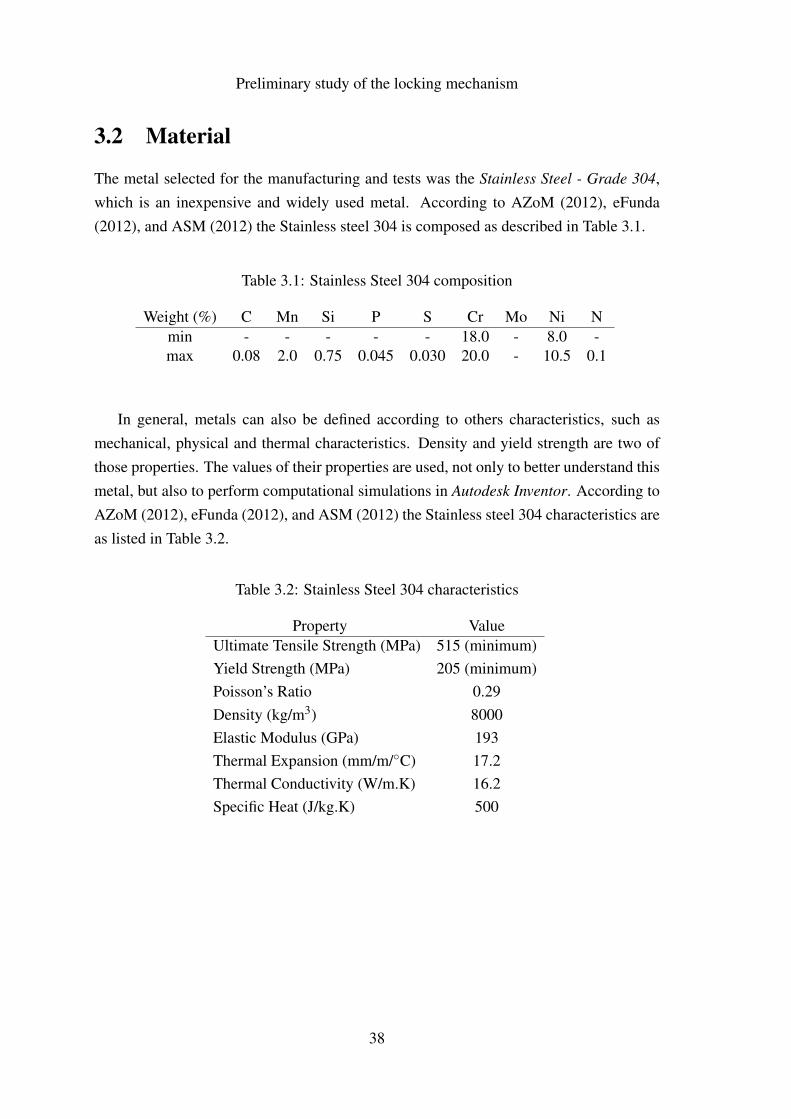
The metal selected for the manufacturing and tests was the Stainless Steel - Grade 304,which is an inexpensive and widely used metal. According to AZoM (2012), eFunda(2012), and ASM (2012) the Stainless steel 304 is composed as described in Table 3.1.
Table 3.1: Stainless Steel 304 composition
Weight (%) C Mn Si P S Cr Mo Ni Nmin - - - - - 18.0 - 8.0 -max 0.08 2.0 0.75 0.045 0.030 20.0 - 10.5 0.1
In general, metals can also be defined according to others characteristics, such asmechanical, physical and thermal characteristics. Density and yield strength are two ofthose properties. The values of their properties are used, not only to better understand thismetal, but also to perform computational simulations in Autodesk Inventor. According toAZoM (2012), eFunda (2012), and ASM (2012) the Stainless steel 304 characteristics areas listed in Table 3.2.
Table 3.2: Stainless Steel 304 characteristics
Property ValueUltimate Tensile Strength (MPa) 515 (minimum)Yield Strength (MPa) 205 (minimum)Poisson’s Ratio 0.29Density (kg/m3) 8000Elastic Modulus (GPa) 193Thermal Expansion (mm/m/◦C) 17.2Thermal Conductivity (W/m.K) 16.2Specific Heat (J/kg.K) 500
38
Preliminary study of the locking mechanism
3.3 Mechanical Solutions
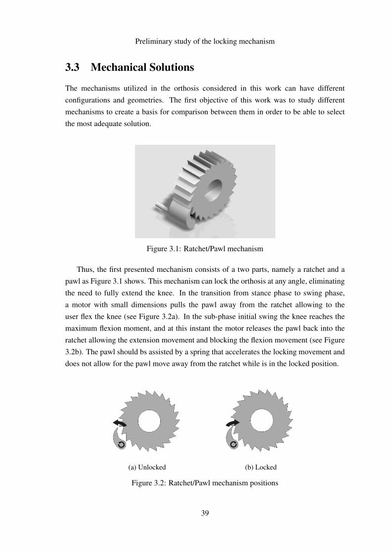
The mechanisms utilized in the orthosis considered in this work can have differentconfigurations and geometries. The first objective of this work was to study differentmechanisms to create a basis for comparison between them in order to be able to selectthe most adequate solution.
Figure 3.1: Ratchet/Pawl mechanism
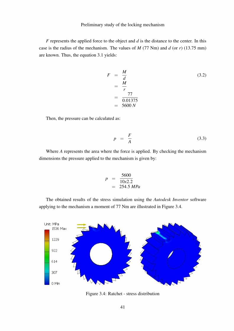
Thus, the first presented mechanism consists of a two parts, namely a ratchet and apawl as Figure 3.1 shows. This mechanism can lock the orthosis at any angle, eliminatingthe need to fully extend the knee. In the transition from stance phase to swing phase,a motor with small dimensions pulls the pawl away from the ratchet allowing to theuser flex the knee (see Figure 3.2a). In the sub-phase initial swing the knee reaches themaximum flexion moment, and at this instant the motor releases the pawl back into theratchet allowing the extension movement and blocking the flexion movement (see Figure3.2b). The pawl should bs assisted by a spring that accelerates the locking movement anddoes not allow for the pawl move away from the ratchet while is in the locked position.
(a) Unlocked (b) Locked
Figure 3.2: Ratchet/Pawl mechanism positions
39

Preliminary study of the locking mechanism
The main dimensions of this mechanism are presented in the Figure 3.3. The diameterof the ratchet is less than 30 mm, and has a hole of 10 mm for the main shaft, that connectsthe lower part of the orthosis to the upper part. The thickness of the ratchet is equalto 10 mm, which leaves 10 mm to the housing and other parts in order to follow therequirements advised by Moreira et al. (2011) and Yakimovich et al. (2006a). The outerdiameter can be smaller, but a smaller mechanism will have less resistance to the appliedmoments to the mechanism during operation. A compromise between size and strengthshould be taken in account.
Figure 3.3: Ratchet dimensions
The pawl (see appendix A) has a height of 10 mm and a minimum thickness of 10 mm.At the center of rotation of the pawl a motor shaft is connect, in the drawing is definedwith 10 mm in length and with a diameter of 2 mm. This values may vary accordingto the chosen motor, for instance, a Radio Control Servo (RC Servo) can not be connectdirectly to the pawl because is too long. In this case the motor is differently located and itis necessary a small mechanism to transmit the movement of the motor.
In order to perform the computational simulation, it is first necessary to know the valueof the load to apply on the mechanism parts. For this purpose, the material properties ofthe stainless steel grade 304 presented in Table 3.2 were used. According to Yakimovichet al. (2006a), the mechanism has to support a moment of 77 Nm, which represents a90 kg orthosis user climbing stairs. In order to know the pressure, it necessary to convertthe moment created by the user to pressure (MPa), according to Hall et al. (1999), momentis given by equation 3.1:
M = F.d (3.1)
40
Preliminary study of the locking mechanism
F represents the applied force to the object and d is the distance to the center. In thiscase is the radius of the mechanism. The values of M (77 Nm) and d (or r) (13.75 mm)are known. Thus, the equation 3.1 yields:
F =Md
(3.2)
=Mr
=77
0.01375= 5600 N
Then, the pressure can be calculated as:
p =FA
(3.3)
Where A represents the area where the force is applied. By checking the mechanismdimensions the pressure applied to the mechanism is given by:
p =5600
10x2.2= 254.5 MPa
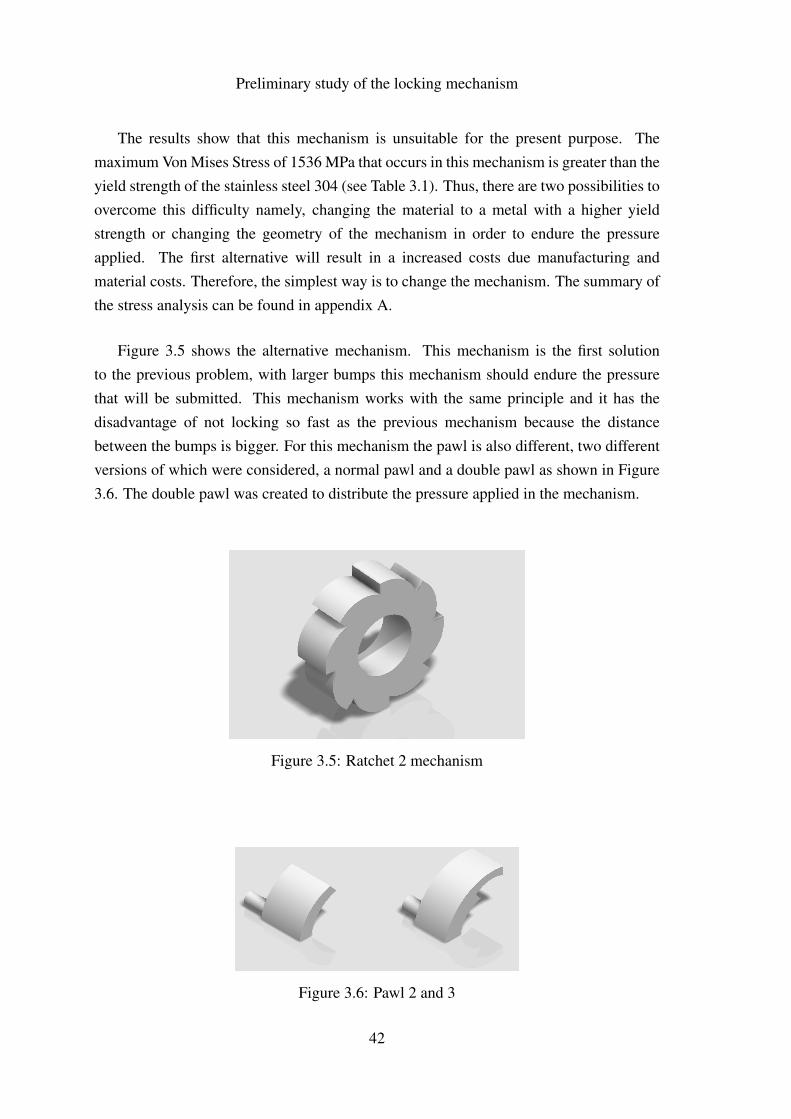
The obtained results of the stress simulation using the Autodesk Inventor softwareapplying to the mechanism a moment of 77 Nm are illustrated in Figure 3.4.
Figure 3.4: Ratchet - stress distribution
41
Preliminary study of the locking mechanism
The results show that this mechanism is unsuitable for the present purpose. Themaximum Von Mises Stress of 1536 MPa that occurs in this mechanism is greater than theyield strength of the stainless steel 304 (see Table 3.1). Thus, there are two possibilities toovercome this difficulty namely, changing the material to a metal with a higher yieldstrength or changing the geometry of the mechanism in order to endure the pressureapplied. The first alternative will result in a increased costs due manufacturing andmaterial costs. Therefore, the simplest way is to change the mechanism. The summary ofthe stress analysis can be found in appendix A.
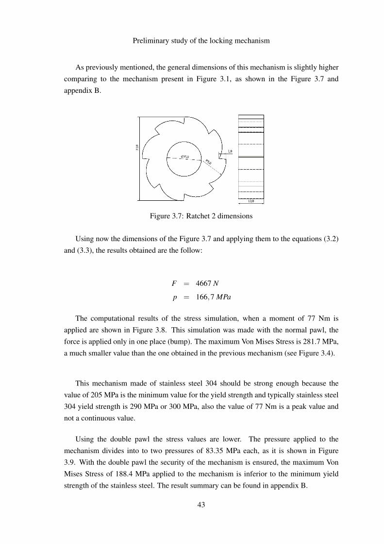
Figure 3.5 shows the alternative mechanism. This mechanism is the first solutionto the previous problem, with larger bumps this mechanism should endure the pressurethat will be submitted. This mechanism works with the same principle and it has thedisadvantage of not locking so fast as the previous mechanism because the distancebetween the bumps is bigger. For this mechanism the pawl is also different, two differentversions of which were considered, a normal pawl and a double pawl as shown in Figure3.6. The double pawl was created to distribute the pressure applied in the mechanism.
Figure 3.5: Ratchet 2 mechanism
Figure 3.6: Pawl 2 and 3
42
Preliminary study of the locking mechanism
As previously mentioned, the general dimensions of this mechanism is slightly highercomparing to the mechanism present in Figure 3.1, as shown in the Figure 3.7 andappendix B.
Figure 3.7: Ratchet 2 dimensions
Using now the dimensions of the Figure 3.7 and applying them to the equations (3.2)and (3.3), the results obtained are the follow:
F = 4667 N
p = 166,7 MPa
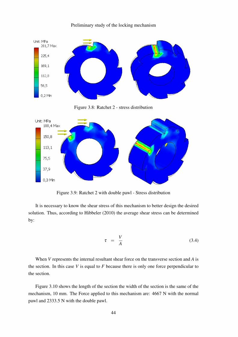
The computational results of the stress simulation, when a moment of 77 Nm isapplied are shown in Figure 3.8. This simulation was made with the normal pawl, theforce is applied only in one place (bump). The maximum Von Mises Stress is 281.7 MPa,a much smaller value than the one obtained in the previous mechanism (see Figure 3.4).
This mechanism made of stainless steel 304 should be strong enough because thevalue of 205 MPa is the minimum value for the yield strength and typically stainless steel304 yield strength is 290 MPa or 300 MPa, also the value of 77 Nm is a peak value andnot a continuous value.
Using the double pawl the stress values are lower. The pressure applied to themechanism divides into to two pressures of 83.35 MPa each, as it is shown in Figure3.9. With the double pawl the security of the mechanism is ensured, the maximum VonMises Stress of 188.4 MPa applied to the mechanism is inferior to the minimum yieldstrength of the stainless steel. The result summary can be found in appendix B.
43
Preliminary study of the locking mechanism
Figure 3.8: Ratchet 2 - stress distribution
Figure 3.9: Ratchet 2 with double pawl - Stress distribution
It is necessary to know the shear stress of this mechanism to better design the desiredsolution. Thus, according to Hibbeler (2010) the average shear stress can be determinedby:
τ =VA
(3.4)
When V represents the internal resultant shear force on the transverse section and A isthe section. In this case V is equal to F because there is only one force perpendicular tothe section.
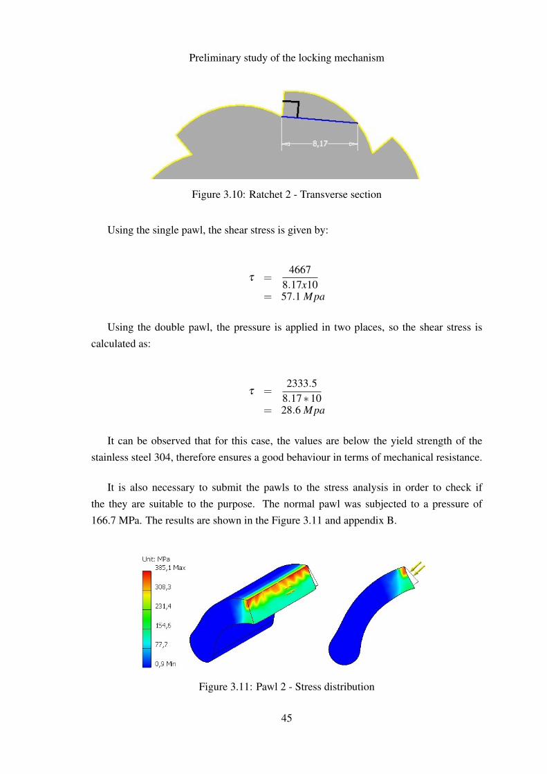
Figure 3.10 shows the length of the section the width of the section is the same of themechanism, 10 mm. The Force applied to this mechanism are: 4667 N with the normalpawl and 2333.5 N with the double pawl.
44
Preliminary study of the locking mechanism
Figure 3.10: Ratchet 2 - Transverse section
Using the single pawl, the shear stress is given by:
τ =4667
8.17x10= 57.1 Mpa
Using the double pawl, the pressure is applied in two places, so the shear stress iscalculated as:
τ =2333.5
8.17∗10= 28.6 Mpa
It can be observed that for this case, the values are below the yield strength of thestainless steel 304, therefore ensures a good behaviour in terms of mechanical resistance.
It is also necessary to submit the pawls to the stress analysis in order to check ifthe they are suitable to the purpose. The normal pawl was subjected to a pressure of166.7 MPa. The results are shown in the Figure 3.11 and appendix B.
Figure 3.11: Pawl 2 - Stress distribution
45
Preliminary study of the locking mechanism
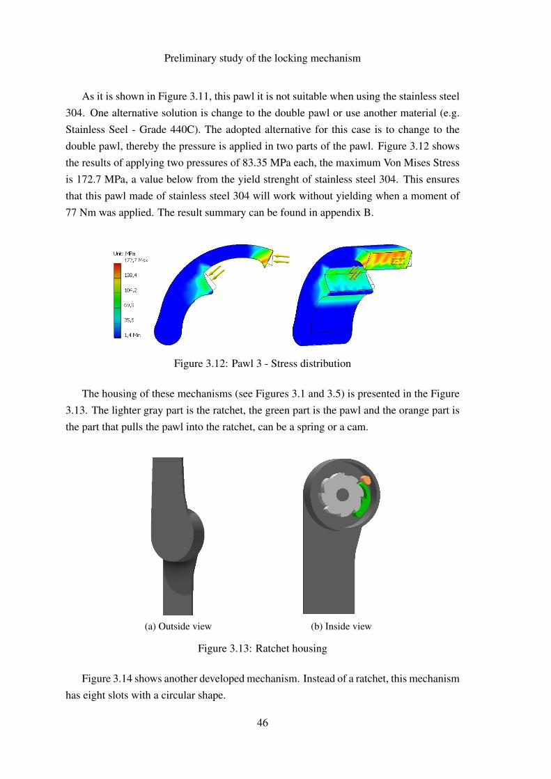
As it is shown in Figure 3.11, this pawl it is not suitable when using the stainless steel304. One alternative solution is change to the double pawl or use another material (e.g.Stainless Seel - Grade 440C). The adopted alternative for this case is to change to thedouble pawl, thereby the pressure is applied in two parts of the pawl. Figure 3.12 showsthe results of applying two pressures of 83.35 MPa each, the maximum Von Mises Stressis 172.7 MPa, a value below from the yield strenght of stainless steel 304. This ensuresthat this pawl made of stainless steel 304 will work without yielding when a moment of77 Nm was applied. The result summary can be found in appendix B.
Figure 3.12: Pawl 3 - Stress distribution
The housing of these mechanisms (see Figures 3.1 and 3.5) is presented in the Figure3.13. The lighter gray part is the ratchet, the green part is the pawl and the orange part isthe part that pulls the pawl into the ratchet, can be a spring or a cam.
(a) Outside view (b) Inside view
Figure 3.13: Ratchet housing
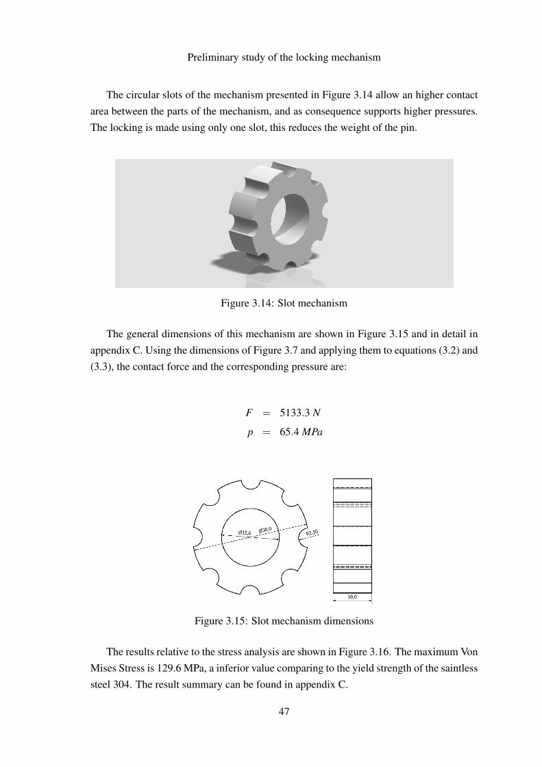
Figure 3.14 shows another developed mechanism. Instead of a ratchet, this mechanismhas eight slots with a circular shape.
46
Preliminary study of the locking mechanism
The circular slots of the mechanism presented in Figure 3.14 allow an higher contactarea between the parts of the mechanism, and as consequence supports higher pressures.The locking is made using only one slot, this reduces the weight of the pin.
Figure 3.14: Slot mechanism
The general dimensions of this mechanism are shown in Figure 3.15 and in detail inappendix C. Using the dimensions of Figure 3.7 and applying them to equations (3.2) and(3.3), the contact force and the corresponding pressure are:
F = 5133.3 N
p = 65.4 MPa
Figure 3.15: Slot mechanism dimensions
The results relative to the stress analysis are shown in Figure 3.16. The maximum VonMises Stress is 129.6 MPa, a inferior value comparing to the yield strength of the saintlesssteel 304. The result summary can be found in appendix C.
47
Preliminary study of the locking mechanism
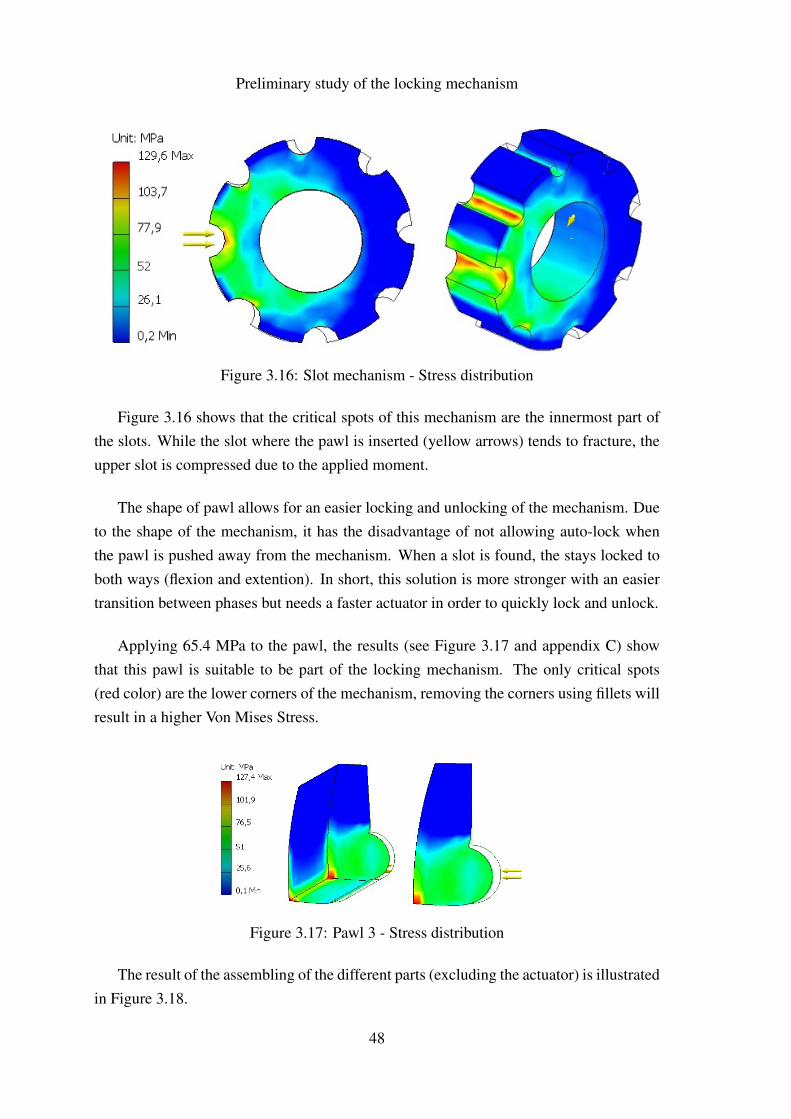
Figure 3.16: Slot mechanism - Stress distribution
Figure 3.16 shows that the critical spots of this mechanism are the innermost part ofthe slots. While the slot where the pawl is inserted (yellow arrows) tends to fracture, theupper slot is compressed due to the applied moment.
The shape of pawl allows for an easier locking and unlocking of the mechanism. Dueto the shape of the mechanism, it has the disadvantage of not allowing auto-lock whenthe pawl is pushed away from the mechanism. When a slot is found, the stays locked toboth ways (flexion and extention). In short, this solution is more stronger with an easiertransition between phases but needs a faster actuator in order to quickly lock and unlock.
Applying 65.4 MPa to the pawl, the results (see Figure 3.17 and appendix C) showthat this pawl is suitable to be part of the locking mechanism. The only critical spots(red color) are the lower corners of the mechanism, removing the corners using fillets willresult in a higher Von Mises Stress.
Figure 3.17: Pawl 3 - Stress distribution
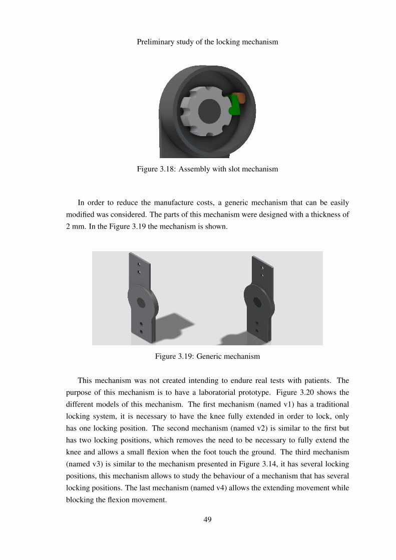
The result of the assembling of the different parts (excluding the actuator) is illustratedin Figure 3.18.
48
Preliminary study of the locking mechanism
Figure 3.18: Assembly with slot mechanism
In order to reduce the manufacture costs, a generic mechanism that can be easilymodified was considered. The parts of this mechanism were designed with a thickness of2 mm. In the Figure 3.19 the mechanism is shown.
Figure 3.19: Generic mechanism
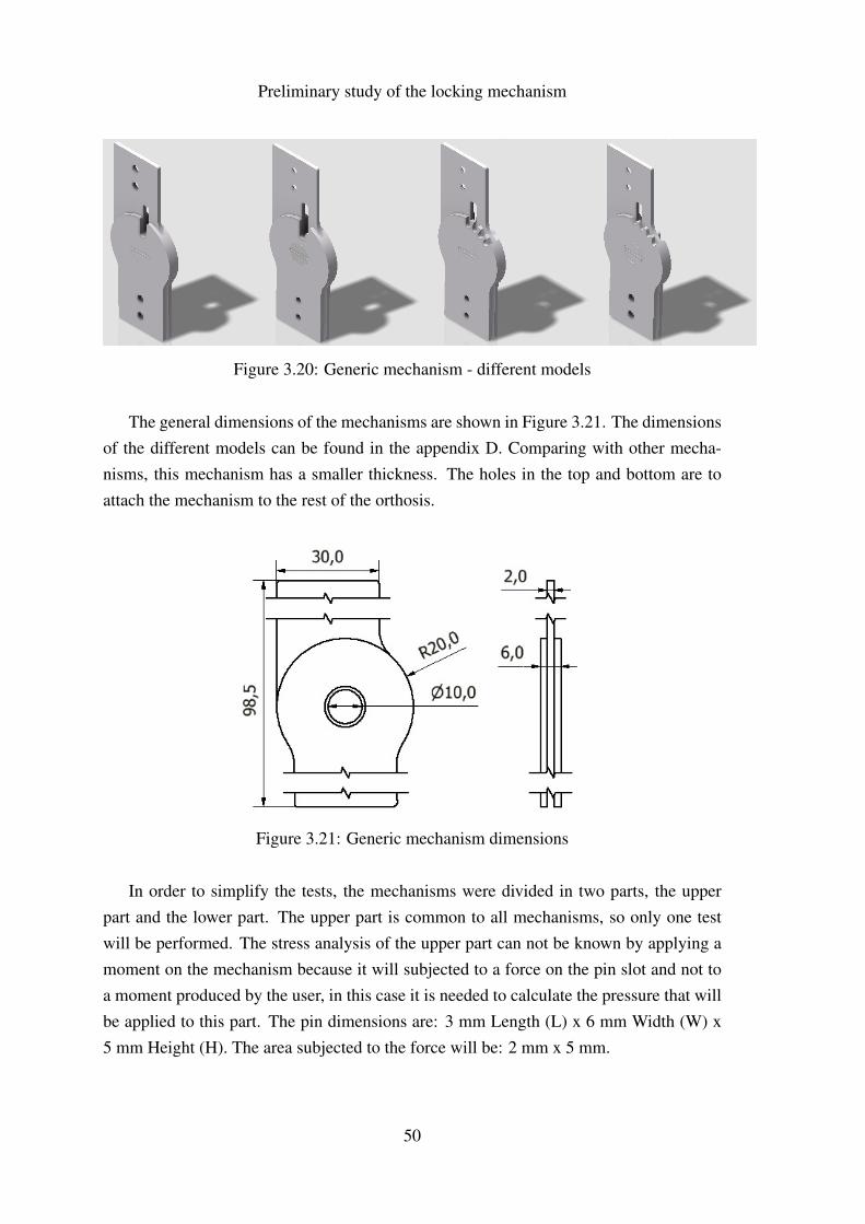
This mechanism was not created intending to endure real tests with patients. Thepurpose of this mechanism is to have a laboratorial prototype. Figure 3.20 shows thedifferent models of this mechanism. The first mechanism (named v1) has a traditionallocking system, it is necessary to have the knee fully extended in order to lock, onlyhas one locking position. The second mechanism (named v2) is similar to the first buthas two locking positions, which removes the need to be necessary to fully extend theknee and allows a small flexion when the foot touch the ground. The third mechanism(named v3) is similar to the mechanism presented in Figure 3.14, it has several lockingpositions, this mechanism allows to study the behaviour of a mechanism that has severallocking positions. The last mechanism (named v4) allows the extending movement whileblocking the flexion movement.
49
Preliminary study of the locking mechanism
Figure 3.20: Generic mechanism - different models
The general dimensions of the mechanisms are shown in Figure 3.21. The dimensionsof the different models can be found in the appendix D. Comparing with other mecha-nisms, this mechanism has a smaller thickness. The holes in the top and bottom are toattach the mechanism to the rest of the orthosis.
Figure 3.21: Generic mechanism dimensions
In order to simplify the tests, the mechanisms were divided in two parts, the upperpart and the lower part. The upper part is common to all mechanisms, so only one testwill be performed. The stress analysis of the upper part can not be known by applying amoment on the mechanism because it will subjected to a force on the pin slot and not toa moment produced by the user, in this case it is needed to calculate the pressure that willbe applied to this part. The pin dimensions are: 3 mm Length (L) x 6 mm Width (W) x5 mm Height (H). The area subjected to the force will be: 2 mm x 5 mm.
50
Preliminary study of the locking mechanism
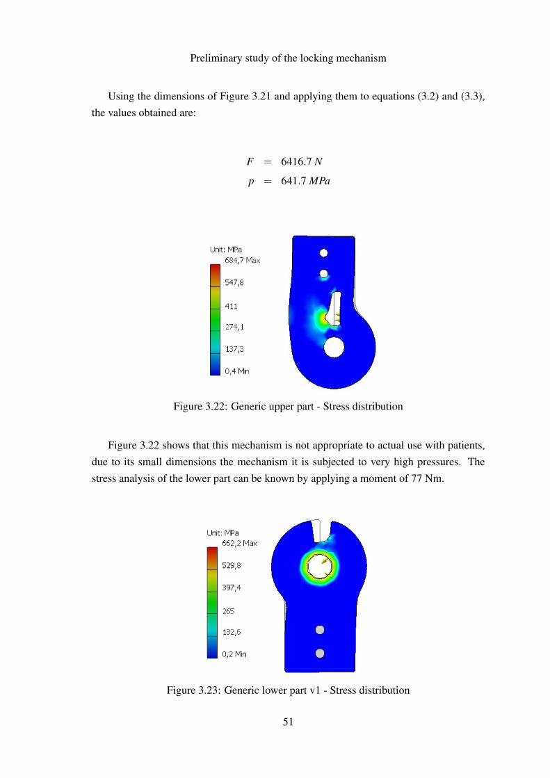
Using the dimensions of Figure 3.21 and applying them to equations (3.2) and (3.3),the values obtained are:
F = 6416.7 N
p = 641.7 MPa
Figure 3.22: Generic upper part - Stress distribution
Figure 3.22 shows that this mechanism is not appropriate to actual use with patients,due to its small dimensions the mechanism it is subjected to very high pressures. Thestress analysis of the lower part can be known by applying a moment of 77 Nm.
Figure 3.23: Generic lower part v1 - Stress distribution
51
Preliminary study of the locking mechanism
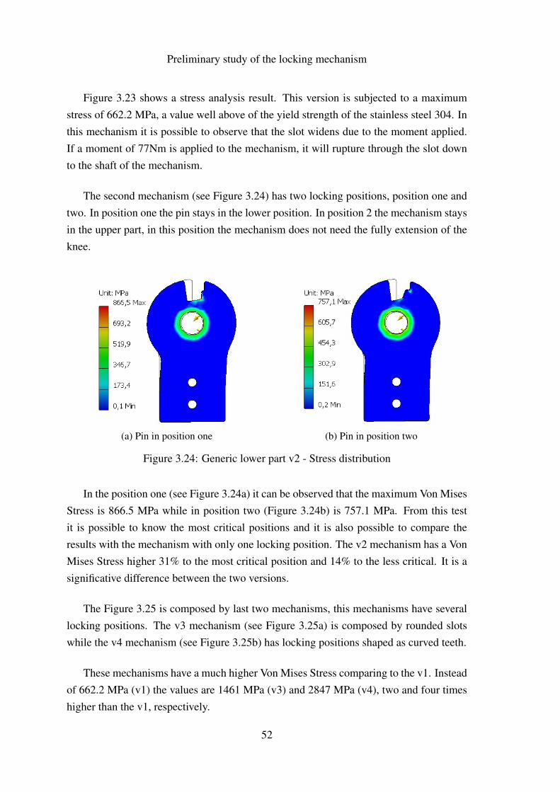
Figure 3.23 shows a stress analysis result. This version is subjected to a maximumstress of 662.2 MPa, a value well above of the yield strength of the stainless steel 304. Inthis mechanism it is possible to observe that the slot widens due to the moment applied.If a moment of 77Nm is applied to the mechanism, it will rupture through the slot downto the shaft of the mechanism.
The second mechanism (see Figure 3.24) has two locking positions, position one andtwo. In position one the pin stays in the lower position. In position 2 the mechanism staysin the upper part, in this position the mechanism does not need the fully extension of theknee.
(a) Pin in position one (b) Pin in position two
Figure 3.24: Generic lower part v2 - Stress distribution
In the position one (see Figure 3.24a) it can be observed that the maximum Von MisesStress is 866.5 MPa while in position two (Figure 3.24b) is 757.1 MPa. From this testit is possible to know the most critical positions and it is also possible to compare theresults with the mechanism with only one locking position. The v2 mechanism has a VonMises Stress higher 31% to the most critical position and 14% to the less critical. It is asignificative difference between the two versions.
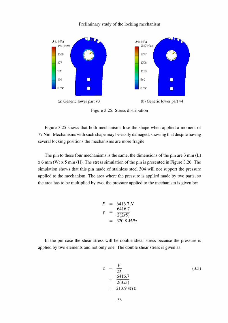
The Figure 3.25 is composed by last two mechanisms, this mechanisms have severallocking positions. The v3 mechanism (see Figure 3.25a) is composed by rounded slotswhile the v4 mechanism (see Figure 3.25b) has locking positions shaped as curved teeth.
These mechanisms have a much higher Von Mises Stress comparing to the v1. Insteadof 662.2 MPa (v1) the values are 1461 MPa (v3) and 2847 MPa (v4), two and four timeshigher than the v1, respectively.
52
Preliminary study of the locking mechanism
(a) Generic lower part v3 (b) Generic lower part v4
Figure 3.25: Stress distribution
Figure 3.25 shows that both mechanisms lose the shape when applied a moment of77 Nm. Mechanisms with such shape may be easily damaged, showing that despite havingseveral locking positions the mechanisms are more fragile.
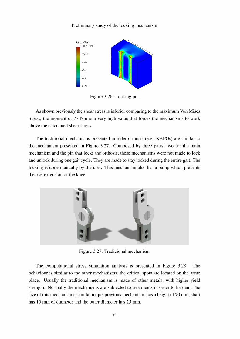
The pin to these four mechanisms is the same, the dimensions of the pin are 3 mm (L)x 6 mm (W) x 5 mm (H). The stress simulation of the pin is presented in Figure 3.26. Thesimulation shows that this pin made of stainless steel 304 will not support the pressureapplied to the mechanism. The area where the pressure is applied made by two parts, sothe area has to be multiplied by two, the pressure applied to the mechanism is given by:
F = 6416.7 N
p =6416.72(2x5)
= 320.8 MPa
In the pin case the shear stress will be double shear stress because the pressure isapplied by two elements and not only one. The double shear stress is given as:
τ =V2A
(3.5)
=6416.72(3x5)
= 213.9 MPa
53
Preliminary study of the locking mechanism
Figure 3.26: Locking pin
As shown previously the shear stress is inferior comparing to the maximum Von MisesStress, the moment of 77 Nm is a very high value that forces the mechanisms to workabove the calculated shear stress.
The traditional mechanisms presented in older orthosis (e.g. KAFOs) are similar tothe mechanism presented in Figure 3.27. Composed by three parts, two for the mainmechanism and the pin that locks the orthosis, these mechanisms were not made to lockand unlock during one gait cycle. They are made to stay locked during the entire gait. Thelocking is done manually by the user. This mechanism also has a bump which preventsthe overextension of the knee.
Figure 3.27: Tradicional mechanism
The computational stress simulation analysis is presented in Figure 3.28. Thebehaviour is similar to the other mechanisms, the critical spots are located on the sameplace. Usually the traditional mechanism is made of other metals, with higher yieldstrength. Normally the mechanisms are subjected to treatments in order to harden. Thesize of this mechanism is similar to que previous mechanism, has a height of 70 mm, shafthas 10 mm of diameter and the outer diameter has 25 mm.
54

Preliminary study of the locking mechanism
(a) Upper part (b) Lower part
Figure 3.28: Traditional mechanism - Stress distribution
55
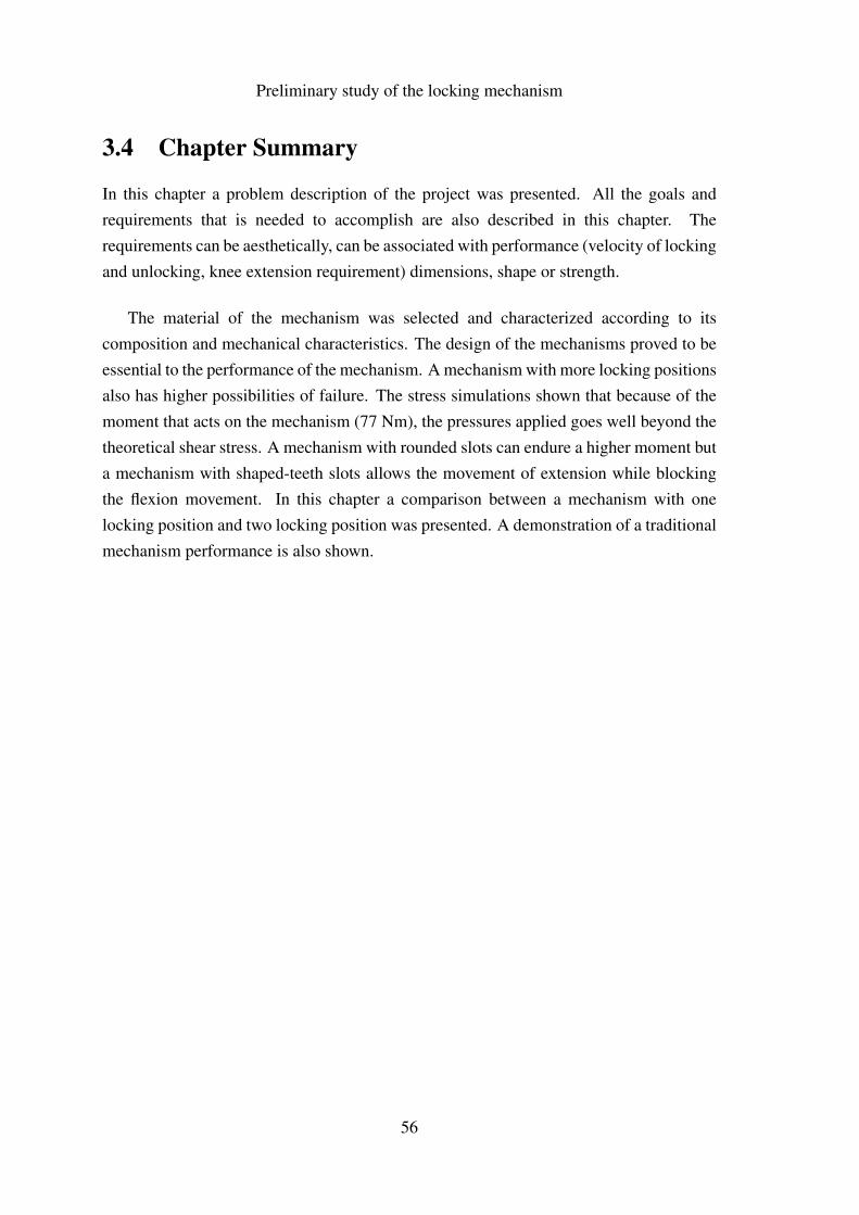
Preliminary study of the locking mechanism
3.4 Chapter Summary
In this chapter a problem description of the project was presented. All the goals andrequirements that is needed to accomplish are also described in this chapter. Therequirements can be aesthetically, can be associated with performance (velocity of lockingand unlocking, knee extension requirement) dimensions, shape or strength.
The material of the mechanism was selected and characterized according to itscomposition and mechanical characteristics. The design of the mechanisms proved to beessential to the performance of the mechanism. A mechanism with more locking positionsalso has higher possibilities of failure. The stress simulations shown that because of themoment that acts on the mechanism (77 Nm), the pressures applied goes well beyond thetheoretical shear stress. A mechanism with rounded slots can endure a higher moment buta mechanism with shaped-teeth slots allows the movement of extension while blockingthe flexion movement. In this chapter a comparison between a mechanism with onelocking position and two locking position was presented. A demonstration of a traditionalmechanism performance is also shown.
56
Chapter 4
Preliminary study of the electronics
57
Preliminary study of the electronics
58
Preliminary study of the electronics
4.1 Sensors
The electronics is a very important and complex part of this project. The numerousexisting sensors and actuators, each one with specific gamma and working principlerequire a weighted choice.
The models available in the market have limitations regarding their use. Eachpathology create a very distinct gait pattern making it very difficult to create an orthosiscapable to meet the different needs of each pathology. With electronics implementation inthe system, it is expected to obtain a better monitoring of the gait cycle allowing to servea wider range of pathologies with only one mechatronic system.
There are many types of measuring the human motion characteristics, to do so can beused devices such as accelerometers, gyroscopes, rotary encoders, among others. For thisproject it is necessary to choose sensors with low profile due to the dimensions limitations.Some devices combine several types of sensors in one Printed Circuit Board (PCB), beingInertial Measurement Unit (IMU) one of the devices. An IMU is a very good set of sensorsto measure human motion, which is composed by an accelerometer and a gyroscope.The more expensive IMUs are also composed by magnometers and barometers. Theless expensive IMUs are simply two sensors (sometimes of different companies) placedtogether, this will cause a problems when communicating with the sensors because eachcompany defines communication for its sensors. The more expensive IMUs, usually madeby companies that manufacture its own sensors, have an easier communication becausethey set a standard to all sensors and also the components are protected by a shell. IMUshave a couple of disadvantages namely, the range of used sensors are pre-defined, makingit unsuitable for this project. For this project the dimensions are very important, so thedimensions of the PCB is essential.
Due to the good performance of IMU when measuring the human motion (Zhu andZhou, 2004), it was decided to create a low-cost IMU with the required specifications.To be able to develop a good IMU it is necessary to make an exhaustive study of thecurrently available sensors about the range, output type, sensitivity, interface, mountingtype, voltage supply and dimensions.
The sensors can be divided into two groups according to their output, (analog ordigital). In analog accelerometers, the output is a variable voltage that depends on themeasured value, while in digital sensors the output is made by digital communication,usually by Inter-Integrated Circuit (I2C) or Serial Peripheral Interface (SPI).
59
Preliminary study of the electronics
Systems with analog sensors have an higher power consumption not only becauseof the sensors but using the analog channels of microcontrollers require more energy towork. Power consumption is a very important subject nowadays. For this project onlywas researched sensors with digital output due to low energy consumption.
There are many accelerometers manufacturers, for this project the first search waslimited to the main stores that ship electronic material to Portugal, Mouser Elec-
tronics (www.mouser.com), Digi-Key Corporation (www.digikey.com), RS (www.pt.rs-online.com), and Farnell (www.farnell.com). The considered manufacturers are listedbelow:
• Analog Devices;
• Bosch Sensortec;
• Freescale;
• Kionix;
• STMicroelectronics;
• VTI Technologies.
In order to refine the search it was defined some pre-defined criteria namely, theacceleration range should be less than 2g, the output must be digital and the voltagesupply must be between 3.3V and 5V because the microcontrollers operate within thesevalues. Table 4.1 shows the sensors characteristics that meets these pre-defined criteria.
Table 4.1: Accelerometers - Analog Devices
Model Axis Accel. Range Sensitivity VoltageADIS16003 - X,Y 1.7g 820 LSB/g 3V - 5.25VADIS16201 - X,Y 1.7g 216.2 LSB/g 3V - 3.60VADXL312 - X,Y,Z 1.5g - 12g 345LSB/g 2V - 3.60V
Table 4.2: Accelerometer - Bosch Sensortec
Model Axis Accel. Range Sensitivity VoltageBMA180 - X,Y,Z 1g - 16g 8192 LSB/g 1.62V - 3.6V
Table 4.2 shows that Bosch Sensortec only has one sensor that meets the requirements.In turn, the companies Freescale, Kionix and STMicroelectronics does not have sensors
60
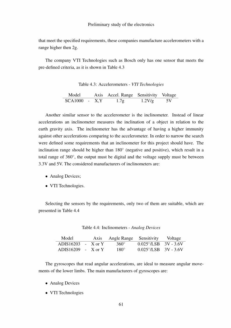
Preliminary study of the electronics
that meet the specified requirements, these companies manufacture accelerometers with arange higher then 2g.
The company VTI Technologies such as Bosch only has one sensor that meets thepre-defined criteria, as it is shown in Table 4.3
Table 4.3: Accelerometers - VTI Technologies
Model Axis Accel. Range Sensitivity VoltageSCA1000 - X,Y 1.7g 1.2V/g 5V
Another similar sensor to the accelerometer is the inclinometer. Instead of linearaccelerations an inclinometer measures the inclination of a object in relation to theearth gravity axis. The inclinometer has the advantage of having a higher immunityagainst other accelerations comparing to the accelerometer. In order to narrow the searchwere defined some requirements that an inclinometer for this project should have. Theinclination range should be higher than 180◦ (negative and positive), which result in atotal range of 360◦, the output must be digital and the voltage supply must be between3.3V and 5V. The considered manufacturers of inclinometers are:
• Analog Devices;
• VTI Technologies.
Selecting the sensors by the requirements, only two of them are suitable, which arepresented in Table 4.4
Table 4.4: Inclinometers - Analog Devices
Model Axis Angle Range Sensitivity VoltageADIS16203 - X or Y 360◦ 0.025◦/LSB 3V - 3.6VADIS16209 - X or Y 180◦ 0.025◦/LSB 3V - 3.6V
The gyroscopes that read angular accelerations, are ideal to measure angular move-ments of the lower limbs. The main manufacturers of gyroscopes are:
• Analog Devices
• VTI Technologies
61
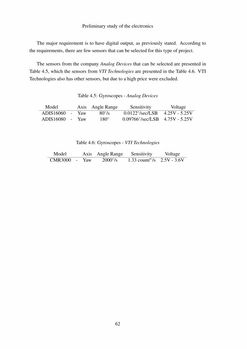
Preliminary study of the electronics
The major requirement is to have digital output, as previously stated. According tothe requirements, there are few sensors that can be selected for this type of project.
The sensors from the company Analog Devices that can be selected are presented inTable 4.5, which the sensors from VTI Technologies are presented in the Table 4.6. VTITechnologies also has other sensors, but due to a high price were excluded.
Table 4.5: Gyroscopes - Analog Devices
Model Axis Angle Range Sensitivity VoltageADIS16060 - Yaw 80◦/s 0.0122◦/sec/LSB 4.25V - 5.25VADIS16080 - Yaw 180◦ 0.09766◦/sec/LSB 4.75V - 5.25V
Table 4.6: Gyroscopes - VTI Technologies
Model Axis Angle Range Sensitivity VoltageCMR3000 - Yaw 2000◦/s 1.33 count/◦/s 2.5V - 3.6V
62
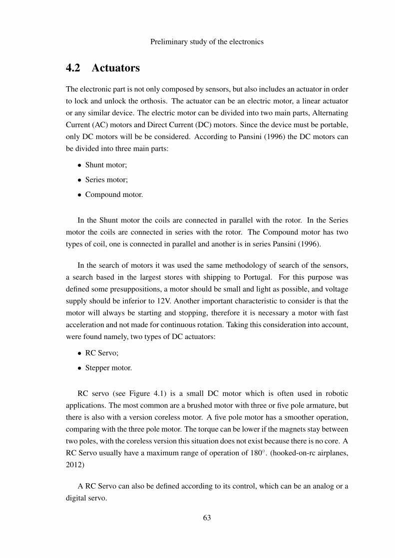
Preliminary study of the electronics
4.2 Actuators
The electronic part is not only composed by sensors, but also includes an actuator in orderto lock and unlock the orthosis. The actuator can be an electric motor, a linear actuatoror any similar device. The electric motor can be divided into two main parts, AlternatingCurrent (AC) motors and Direct Current (DC) motors. Since the device must be portable,only DC motors will be be considered. According to Pansini (1996) the DC motors canbe divided into three main parts:
• Shunt motor;
• Series motor;
• Compound motor.
In the Shunt motor the coils are connected in parallel with the rotor. In the Seriesmotor the coils are connected in series with the rotor. The Compound motor has twotypes of coil, one is connected in parallel and another is in series Pansini (1996).
In the search of motors it was used the same methodology of search of the sensors,a search based in the largest stores with shipping to Portugal. For this purpose wasdefined some presuppositions, a motor should be small and light as possible, and voltagesupply should be inferior to 12V. Another important characteristic to consider is that themotor will always be starting and stopping, therefore it is necessary a motor with fastacceleration and not made for continuous rotation. Taking this consideration into account,were found namely, two types of DC actuators:
• RC Servo;
• Stepper motor.
RC servo (see Figure 4.1) is a small DC motor which is often used in roboticapplications. The most common are a brushed motor with three or five pole armature, butthere is also with a version coreless motor. A five pole motor has a smoother operation,comparing with the three pole motor. The torque can be lower if the magnets stay betweentwo poles, with the coreless version this situation does not exist because there is no core. ARC Servo usually have a maximum range of operation of 180◦. (hooked-on-rc airplanes,2012)
A RC Servo can also be defined according to its control, which can be an analog or adigital servo.
63
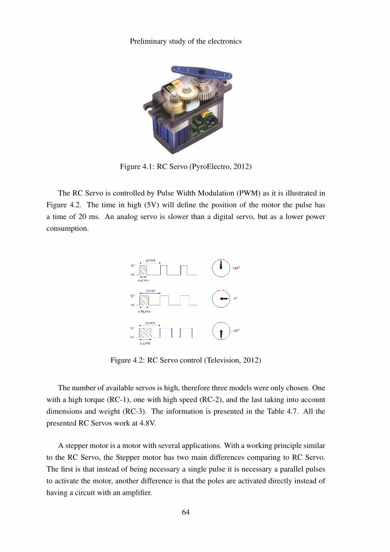
Preliminary study of the electronics
Figure 4.1: RC Servo (PyroElectro, 2012)
The RC Servo is controlled by Pulse Width Modulation (PWM) as it is illustrated inFigure 4.2. The time in high (5V) will define the position of the motor the pulse hasa time of 20 ms. An analog servo is slower than a digital servo, but as a lower powerconsumption.
Figure 4.2: RC Servo control (Television, 2012)
The number of available servos is high, therefore three models were only chosen. Onewith a high torque (RC-1), one with high speed (RC-2), and the last taking into accountdimensions and weight (RC-3). The information is presented in the Table 4.7. All thepresented RC Servos work at 4.8V.
A stepper motor is a motor with several applications. With a working principle similarto the RC Servo, the Stepper motor has two main differences comparing to RC Servo.The first is that instead of being necessary a single pulse it is necessary a parallel pulsesto activate the motor, another difference is that the poles are activated directly instead ofhaving a circuit with an amplifier.
64
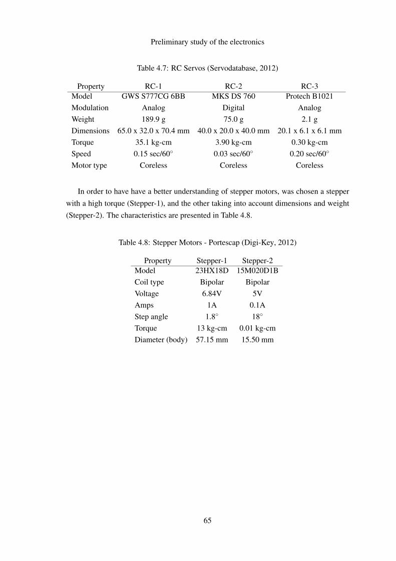
Preliminary study of the electronics
Table 4.7: RC Servos (Servodatabase, 2012)
Property RC-1 RC-2 RC-3Model GWS S777CG 6BB MKS DS 760 Protech B1021Modulation Analog Digital AnalogWeight 189.9 g 75.0 g 2.1 gDimensions 65.0 x 32.0 x 70.4 mm 40.0 x 20.0 x 40.0 mm 20.1 x 6.1 x 6.1 mmTorque 35.1 kg-cm 3.90 kg-cm 0.30 kg-cmSpeed 0.15 sec/60◦ 0.03 sec/60◦ 0.20 sec/60◦
Motor type Coreless Coreless Coreless
In order to have have a better understanding of stepper motors, was chosen a stepperwith a high torque (Stepper-1), and the other taking into account dimensions and weight(Stepper-2). The characteristics are presented in Table 4.8.
Table 4.8: Stepper Motors - Portescap (Digi-Key, 2012)
Property Stepper-1 Stepper-2Model 23HX18D 15M020D1BCoil type Bipolar BipolarVoltage 6.84V 5VAmps 1A 0.1AStep angle 1.8◦ 18◦
Torque 13 kg-cm 0.01 kg-cmDiameter (body) 57.15 mm 15.50 mm
65
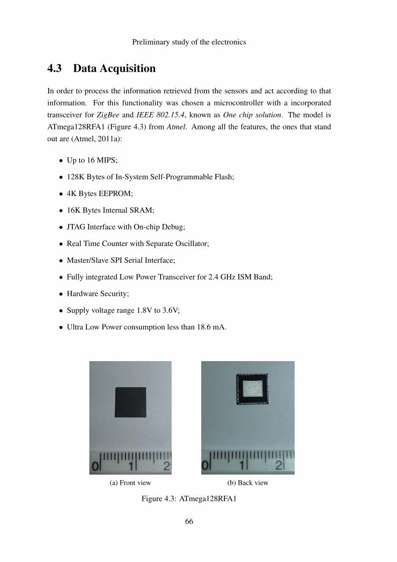
Preliminary study of the electronics
4.3 Data Acquisition
In order to process the information retrieved from the sensors and act according to thatinformation. For this functionality was chosen a microcontroller with a incorporatedtransceiver for ZigBee and IEEE 802.15.4, known as One chip solution. The model isATmega128RFA1 (Figure 4.3) from Atmel. Among all the features, the ones that standout are (Atmel, 2011a):
• Up to 16 MIPS;
• 128K Bytes of In-System Self-Programmable Flash;
• 4K Bytes EEPROM;
• 16K Bytes Internal SRAM;
• JTAG Interface with On-chip Debug;
• Real Time Counter with Separate Oscillator;
• Master/Slave SPI Serial Interface;
• Fully integrated Low Power Transceiver for 2.4 GHz ISM Band;
• Hardware Security;
• Supply voltage range 1.8V to 3.6V;
• Ultra Low Power consumption less than 18.6 mA.
(a) Front view (b) Back view
Figure 4.3: ATmega128RFA1
66
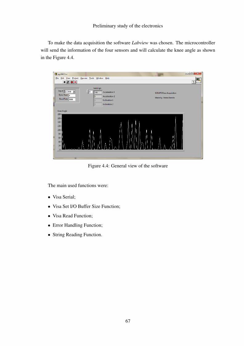
Preliminary study of the electronics
To make the data acquisition the software Labview was chosen. The microcontrollerwill send the information of the four sensors and will calculate the knee angle as shownin the Figure 4.4.
Figure 4.4: General view of the software
The main used functions were:
• Visa Serial;
• Visa Set I/O Buffer Size Function;
• Visa Read Function;
• Error Handling Function;
• String Reading Function.
67

Preliminary study of the electronics
4.4 Chapter Summary
A search of suitable sensors for this project was made. Despite the large number ofexisting sensors, this chapter presemted the number of sensors suitable for this kindof project is small. The best type of sensors for measuring the human motion are:accelerometers, gyroscopes and inclinometers. The main manufactures of this typeof sensors were also indicated. A sample of suitable actuators were also shown inthis chapter, due to a large offer of motors a comparison was made based on theircharacteristics and also their working principle.
The selected microcontroller was the ATmega128RFA1 from ATmega due to itscharacteristics, that is, it has a built-in transceiver which reduces the size of PCB andalso reduces the price.
Finally, in this chapter a brief description of the functions used on the developedprogram is shown. The Labview was the chosen platform.
68
Chapter 5
Development of a New Concept ofLocking System for an OrthosisSCKAFO
69
Development of a New Concept of Locking System for an Orthosis SCKAFO
70
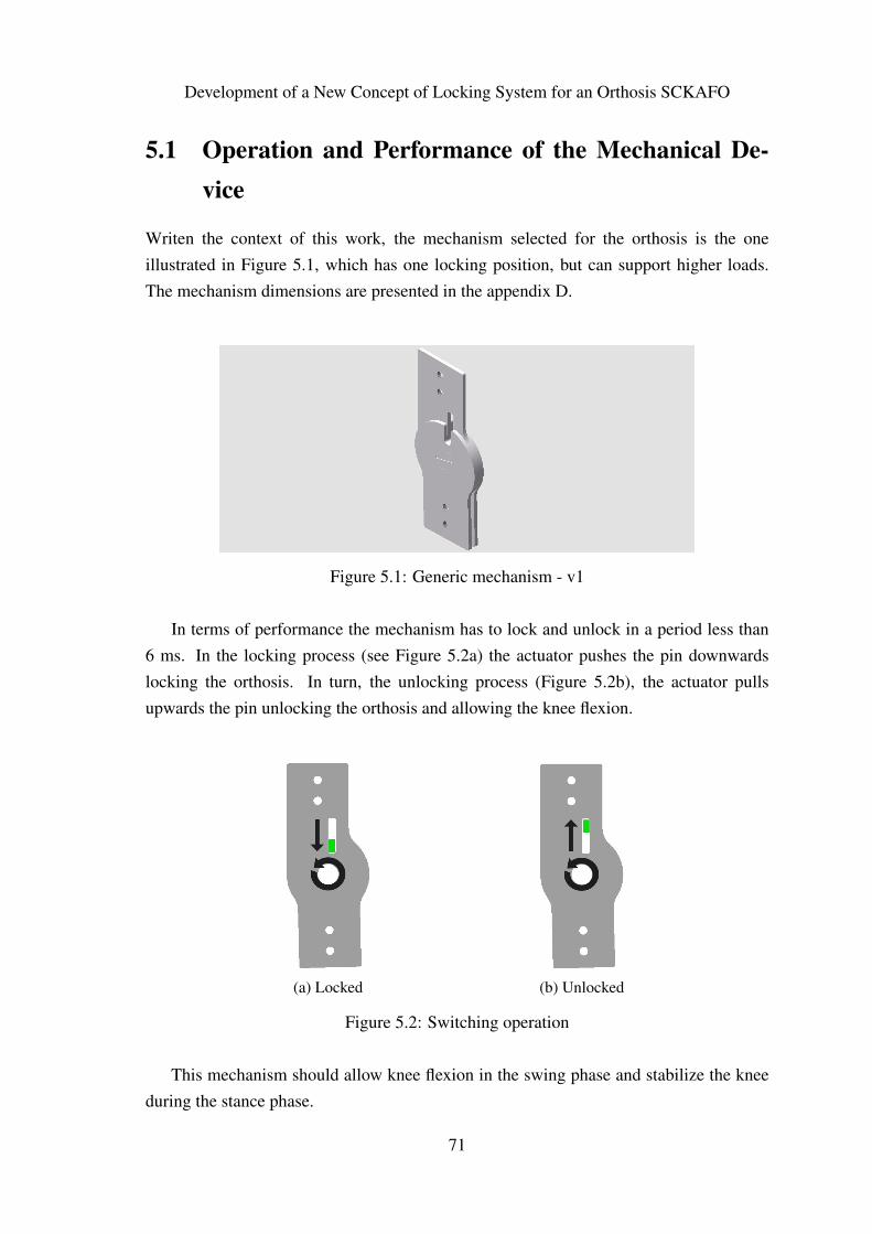
Development of a New Concept of Locking System for an Orthosis SCKAFO
5.1 Operation and Performance of the Mechanical De-vice
Writen the context of this work, the mechanism selected for the orthosis is the oneillustrated in Figure 5.1, which has one locking position, but can support higher loads.The mechanism dimensions are presented in the appendix D.
Figure 5.1: Generic mechanism - v1
In terms of performance the mechanism has to lock and unlock in a period less than6 ms. In the locking process (see Figure 5.2a) the actuator pushes the pin downwardslocking the orthosis. In turn, the unlocking process (Figure 5.2b), the actuator pullsupwards the pin unlocking the orthosis and allowing the knee flexion.
(a) Locked (b) Unlocked
Figure 5.2: Switching operation
This mechanism should allow knee flexion in the swing phase and stabilize the kneeduring the stance phase.
71
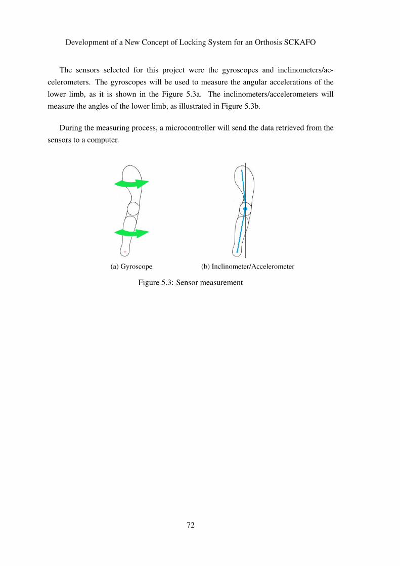
Development of a New Concept of Locking System for an Orthosis SCKAFO
The sensors selected for this project were the gyroscopes and inclinometers/ac-celerometers. The gyroscopes will be used to measure the angular accelerations of thelower limb, as it is shown in the Figure 5.3a. The inclinometers/accelerometers willmeasure the angles of the lower limb, as illustrated in Figure 5.3b.
During the measuring process, a microcontroller will send the data retrieved from thesensors to a computer.
(a) Gyroscope (b) Inclinometer/Accelerometer
Figure 5.3: Sensor measurement
72

Development of a New Concept of Locking System for an Orthosis SCKAFO
5.2 Construction of the Physical Prototype
The physical prototype constructed is made of a stainless steel plate with a thickness of2 mm. The mechanism was manufactured by laser technique. Two different mechanismswere built, one with a slot as presented in the Figure 5.1, and another one without anyslot. With this approach, a simplification is intended, it is needed only one actuator, andthus, a lower power consumption. The only disadvantage of this solution is that only onemechanism is subjected to the pressure. Figure 5.4 shows the mechanism built. The costof this mechanism was 78,46 euros.
(a) With slot (b) Without slot
Figure 5.4: Built mechanism
Figures 5.5 and 5.6 show the five elements that constitute each mechanism. Threeparts belong to the locking system and the remaining two parts belong to the shaft of themechanism.
Figure 5.5: Elements of part one
73
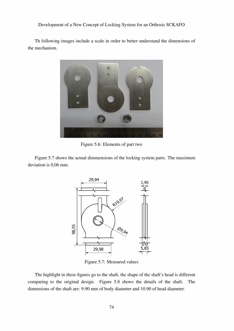
Development of a New Concept of Locking System for an Orthosis SCKAFO
Th following images include a scale in order to better understand the dimensions ofthe mechanism.
Figure 5.6: Elements of part two
Figure 5.7 shows the actual dimmensions of the locking system parts. The maximumdeviation is 0,06 mm.
Figure 5.7: Measured values
The highlight in these figures go to the shaft, the shape of the shaft’s head is differentcomparing to the original design. Figure 5.8 shows the details of the shaft. Thedimensions of the shaft are: 9.90 mm of body diameter and 10.90 of head diameter.
74
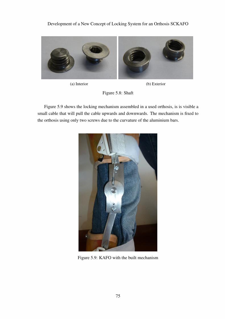
Development of a New Concept of Locking System for an Orthosis SCKAFO
(a) Interior (b) Exterior
Figure 5.8: Shaft
Figure 5.9 shows the locking mechanism assembled in a used orthosis, is is visible asmall cable that will pull the cable upwards and downwards. The mechanism is fixed tothe orthosis using only two screws due to the curvature of the aluminium bars.
Figure 5.9: KAFO with the built mechanism
75

Development of a New Concept of Locking System for an Orthosis SCKAFO
5.3 Electronic System Implementation
With the purpose to develop a SCKAFO it is necessary to design a system that providesautomatic actuation to the orthosis that is to lock and unlock without any human action.One possible way to provide this is to use electronics, by measuring the entire process andacting when it will be necessary according to the human gait progress. The measurementis made by using sensors, namely:
• Inclinometer: ADIS16203 from Analog Devices;
• Gyroscope: CMR3000 from VTI Technologies.
An inclinometer was selected instead of an accelerometer because it has greaterimmunity to noise from accelerations from other axis, for instance, when the footmakes the downward movement towards the floor the entire lower limb is subject toan acceleration that does not have interest in measuring and can interfere with themeasurement of the angle of the lower limb. The choice of the sensors was limited due tothe budget constrains and the available stock in stores.
Due to the low budget available for this project was not possible to work withdevelopment boards, so it was decided to make new development boards with the desireddimensions.
In order to make a successful development board it is necessary to study the datasheetsof the sensors and corresponding development boards. The datasheet of the ADIS16203sensor does not provide any kind of information about how a development board with thissensor should be, but searching the datasheet of the development board is retrieved theinformation presented in Figure 5.10.
Figure 5.10: iSensor Inclinometer/Accelerometer Evaluation Board (Devices, 2007)
76
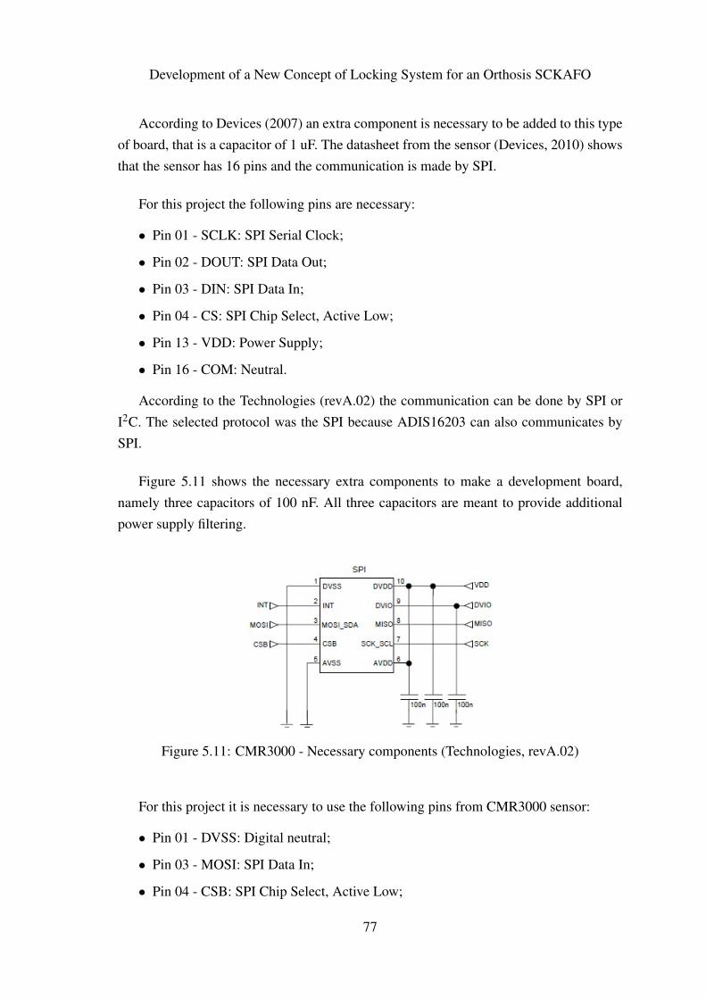
Development of a New Concept of Locking System for an Orthosis SCKAFO
According to Devices (2007) an extra component is necessary to be added to this typeof board, that is a capacitor of 1 uF. The datasheet from the sensor (Devices, 2010) showsthat the sensor has 16 pins and the communication is made by SPI.
For this project the following pins are necessary:
• Pin 01 - SCLK: SPI Serial Clock;
• Pin 02 - DOUT: SPI Data Out;
• Pin 03 - DIN: SPI Data In;
• Pin 04 - CS: SPI Chip Select, Active Low;
• Pin 13 - VDD: Power Supply;
• Pin 16 - COM: Neutral.
According to the Technologies (revA.02) the communication can be done by SPI orI2C. The selected protocol was the SPI because ADIS16203 can also communicates bySPI.
Figure 5.11 shows the necessary extra components to make a development board,namely three capacitors of 100 nF. All three capacitors are meant to provide additionalpower supply filtering.
Figure 5.11: CMR3000 - Necessary components (Technologies, revA.02)
For this project it is necessary to use the following pins from CMR3000 sensor:
• Pin 01 - DVSS: Digital neutral;
• Pin 03 - MOSI: SPI Data In;
• Pin 04 - CSB: SPI Chip Select, Active Low;
77
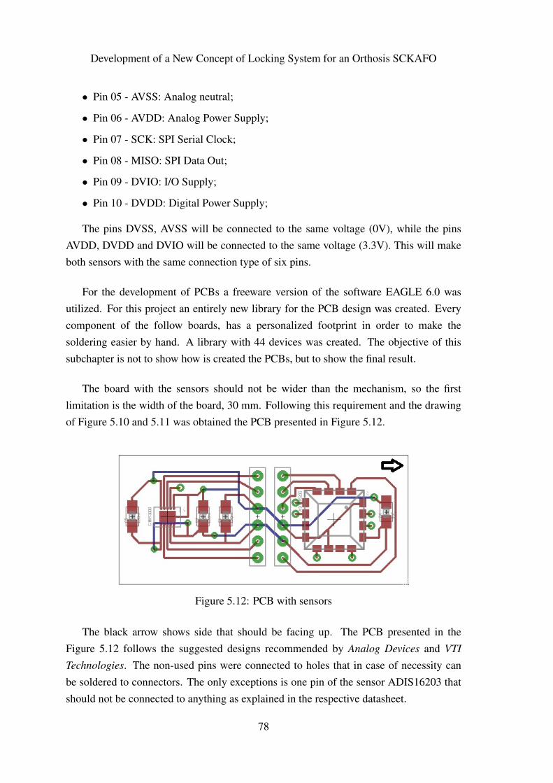
Development of a New Concept of Locking System for an Orthosis SCKAFO
• Pin 05 - AVSS: Analog neutral;
• Pin 06 - AVDD: Analog Power Supply;
• Pin 07 - SCK: SPI Serial Clock;
• Pin 08 - MISO: SPI Data Out;
• Pin 09 - DVIO: I/O Supply;
• Pin 10 - DVDD: Digital Power Supply;
The pins DVSS, AVSS will be connected to the same voltage (0V), while the pinsAVDD, DVDD and DVIO will be connected to the same voltage (3.3V). This will makeboth sensors with the same connection type of six pins.
For the development of PCBs a freeware version of the software EAGLE 6.0 wasutilized. For this project an entirely new library for the PCB design was created. Everycomponent of the follow boards, has a personalized footprint in order to make thesoldering easier by hand. A library with 44 devices was created. The objective of thissubchapter is not to show how is created the PCBs, but to show the final result.
The board with the sensors should not be wider than the mechanism, so the firstlimitation is the width of the board, 30 mm. Following this requirement and the drawingof Figure 5.10 and 5.11 was obtained the PCB presented in Figure 5.12.
Figure 5.12: PCB with sensors
The black arrow shows side that should be facing up. The PCB presented in theFigure 5.12 follows the suggested designs recommended by Analog Devices and VTI
Technologies. The non-used pins were connected to holes that in case of necessity canbe soldered to connectors. The only exceptions is one pin of the sensor ADIS16203 thatshould not be connected to anything as explained in the respective datasheet.
78

Development of a New Concept of Locking System for an Orthosis SCKAFO
In appendix E is shown the full schematic. The total price of the presented board arelisted in Table 5.1.
Table 5.1: Sensor PCB cost
Element Price (in Euros)ADIS16203 49,91CMR3000 22,48Capacitor 1uF 0,063 capacitors 100nF 0,0612 connectors 0,60PCB 18.67Total cost: 91,78
Table 5.1 shows that doing a personalized board is much cheaper than buying a madeone. However, it has one big risk, that is a bad soldered or a bad designed board will notwork.
According to Atmel (2011b), in order to design a PCB with ATmega128RFA1microcontroller with wireless communication needs the configuration presented in theFigure 5.13. The full description can be found in the microcontroller datasheet.
Figure 5.13: ATmega128RFA1 schematic
It should be mentioned that due to the delay in receiving some of the boughtcomponents, it was necessary to design two boards. One with communication by wire andanother one with wireless communication, as Figures 5.14 and 5.15 depict, respectively.
79
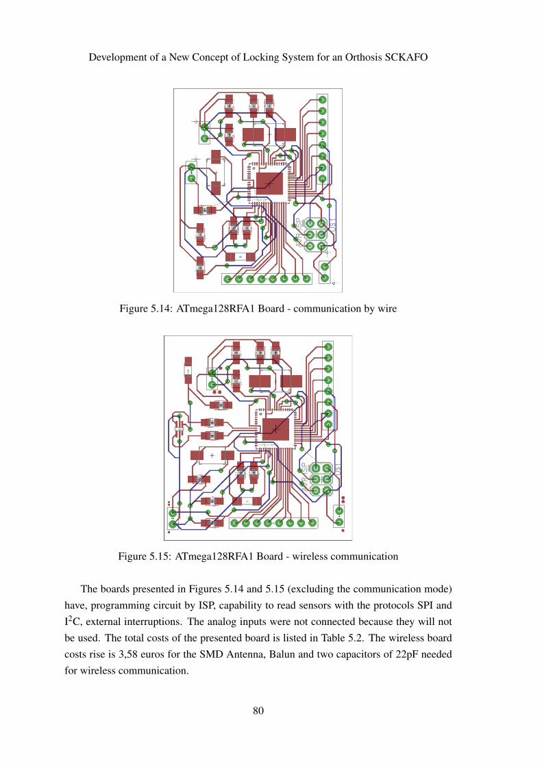
Development of a New Concept of Locking System for an Orthosis SCKAFO
Figure 5.14: ATmega128RFA1 Board - communication by wire
Figure 5.15: ATmega128RFA1 Board - wireless communication
The boards presented in Figures 5.14 and 5.15 (excluding the communication mode)have, programming circuit by ISP, capability to read sensors with the protocols SPI andI2C, external interruptions. The analog inputs were not connected because they will notbe used. The total costs of the presented board is listed in Table 5.2. The wireless boardcosts rise is 3,58 euros for the SMD Antenna, Balun and two capacitors of 22pF neededfor wireless communication.
80
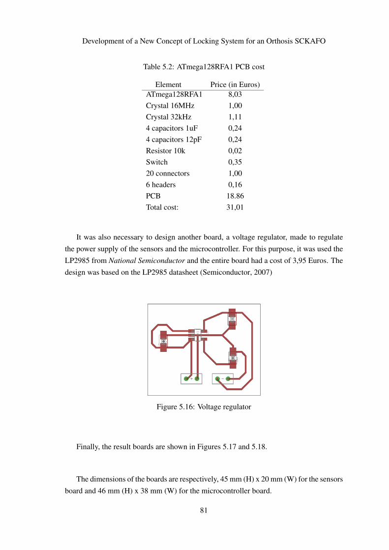
Development of a New Concept of Locking System for an Orthosis SCKAFO
Table 5.2: ATmega128RFA1 PCB cost
Element Price (in Euros)ATmega128RFA1 8,03Crystal 16MHz 1,00Crystal 32kHz 1,114 capacitors 1uF 0,244 capacitors 12pF 0,24Resistor 10k 0,02Switch 0,3520 connectors 1,006 headers 0,16PCB 18.86Total cost: 31,01
It was also necessary to design another board, a voltage regulator, made to regulatethe power supply of the sensors and the microcontroller. For this purpose, it was used theLP2985 from National Semiconductor and the entire board had a cost of 3,95 Euros. Thedesign was based on the LP2985 datasheet (Semiconductor, 2007)
Figure 5.16: Voltage regulator
Finally, the result boards are shown in Figures 5.17 and 5.18.
The dimensions of the boards are respectively, 45 mm (H) x 20 mm (W) for the sensorsboard and 46 mm (H) x 38 mm (W) for the microcontroller board.
81
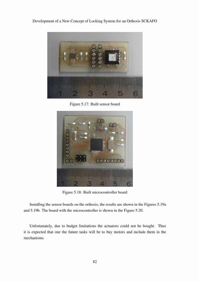
Development of a New Concept of Locking System for an Orthosis SCKAFO
Figure 5.17: Built sensor board
Figure 5.18: Built microcontroller board
Installing the sensor boards on the orthosis, the results are shown in the Figures 5.19aand 5.19b. The board with the microcontroller is shown in the Figure 5.20.
Unfortunately, due to budget limitations the actuators could not be bought. Thusit is expected that one the future tasks will be to buy motors and include them in themechanisms.
82
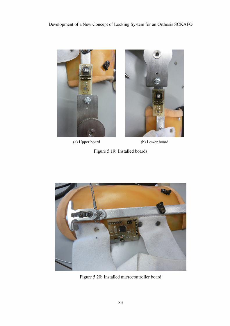
Development of a New Concept of Locking System for an Orthosis SCKAFO
(a) Upper board (b) Lower board
Figure 5.19: Installed boards
Figure 5.20: Installed microcontroller board
83
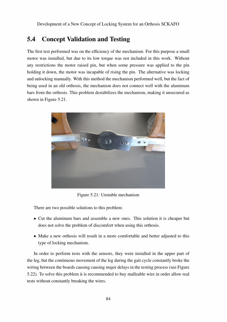
Development of a New Concept of Locking System for an Orthosis SCKAFO
5.4 Concept Validation and Testing
The first test performed was on the efficiency of the mechanism. For this purpose a smallmotor was installed, but due to its low torque was not included in this work. Withoutany restrictions the motor raised pin, but when some pressure was applied to the pinholding it down, the motor was incapable of rising the pin. The alternative was lockingand unlocking manually. With this method the mechanism performed well, but the fact ofbeing used in an old orthosis, the mechanism does not connect well with the aluminumbars from the orthosis. This problem destabilizes the mechanism, making it unsecured asshown in Figure 5.21.
Figure 5.21: Unstable mechanism
There are two possible solutions to this problem:
• Cut the aluminum bars and assemble a new ones. This solution it is cheaper butdoes not solve the problem of discomfort when using this orthosis.
• Make a new orthosis will result in a more comfortable and better adjusted to thistype of locking mechanism.
In order to perform tests with the sensors, they were installed in the upper part ofthe leg, but the continuous movement of the leg during the gait cycle constantly broke thewiring between the boards causing causing major delays in the testing process (see Figure5.22). To solve this problem it is recommended to buy malleable wire in order allow realtests without constantly breaking the wires.
84
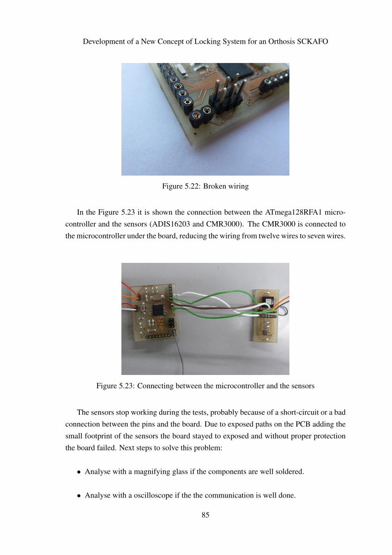
Development of a New Concept of Locking System for an Orthosis SCKAFO
Figure 5.22: Broken wiring
In the Figure 5.23 it is shown the connection between the ATmega128RFA1 micro-controller and the sensors (ADIS16203 and CMR3000). The CMR3000 is connected tothe microcontroller under the board, reducing the wiring from twelve wires to seven wires.
Figure 5.23: Connecting between the microcontroller and the sensors
The sensors stop working during the tests, probably because of a short-circuit or a badconnection between the pins and the board. Due to exposed paths on the PCB adding thesmall footprint of the sensors the board stayed to exposed and without proper protectionthe board failed. Next steps to solve this problem:
• Analyse with a magnifying glass if the components are well soldered.
• Analyse with a oscilloscope if the the communication is well done.
85
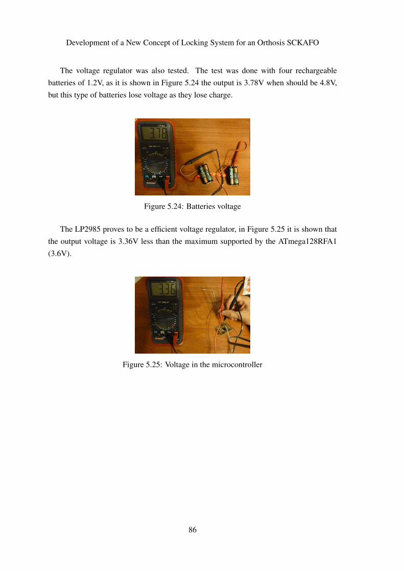
Development of a New Concept of Locking System for an Orthosis SCKAFO
The voltage regulator was also tested. The test was done with four rechargeablebatteries of 1.2V, as it is shown in Figure 5.24 the output is 3.78V when should be 4.8V,but this type of batteries lose voltage as they lose charge.
Figure 5.24: Batteries voltage
The LP2985 proves to be a efficient voltage regulator, in Figure 5.25 it is shown thatthe output voltage is 3.36V less than the maximum supported by the ATmega128RFA1(3.6V).
Figure 5.25: Voltage in the microcontroller
86
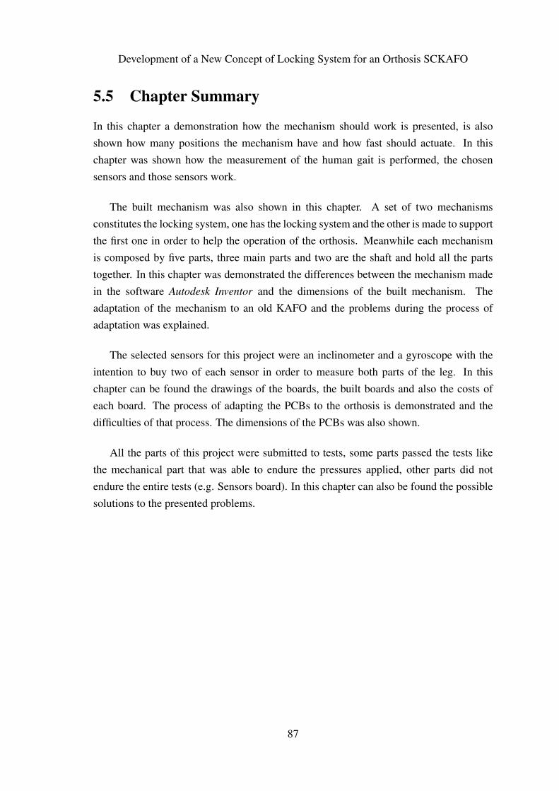
Development of a New Concept of Locking System for an Orthosis SCKAFO
5.5 Chapter Summary
In this chapter a demonstration how the mechanism should work is presented, is alsoshown how many positions the mechanism have and how fast should actuate. In thischapter was shown how the measurement of the human gait is performed, the chosensensors and those sensors work.
The built mechanism was also shown in this chapter. A set of two mechanismsconstitutes the locking system, one has the locking system and the other is made to supportthe first one in order to help the operation of the orthosis. Meanwhile each mechanismis composed by five parts, three main parts and two are the shaft and hold all the partstogether. In this chapter was demonstrated the differences between the mechanism madein the software Autodesk Inventor and the dimensions of the built mechanism. Theadaptation of the mechanism to an old KAFO and the problems during the process ofadaptation was explained.
The selected sensors for this project were an inclinometer and a gyroscope with theintention to buy two of each sensor in order to measure both parts of the leg. In thischapter can be found the drawings of the boards, the built boards and also the costs ofeach board. The process of adapting the PCBs to the orthosis is demonstrated and thedifficulties of that process. The dimensions of the PCBs was also shown.
All the parts of this project were submitted to tests, some parts passed the tests likethe mechanical part that was able to endure the pressures applied, other parts did notendure the entire tests (e.g. Sensors board). In this chapter can also be found the possiblesolutions to the presented problems.
87

Development of a New Concept of Locking System for an Orthosis SCKAFO
88

Chapter 6
Conclusions and Future Work
89

Conclusions and Future Work
90
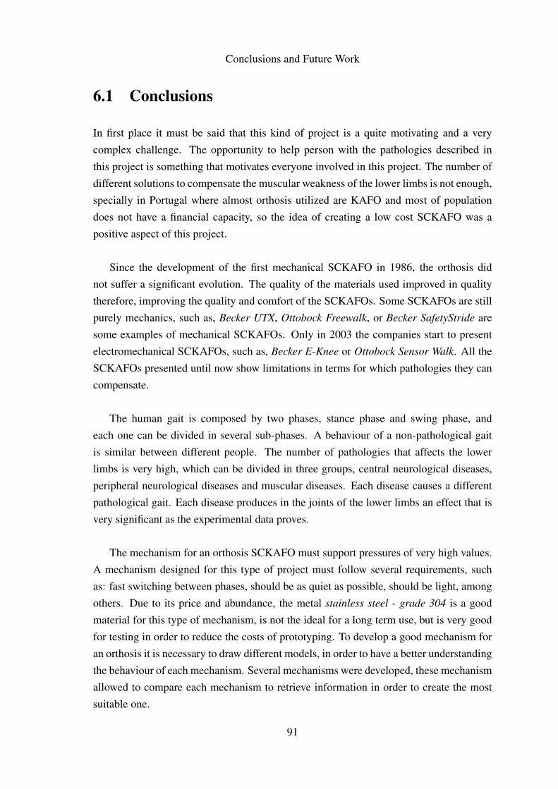
Conclusions and Future Work
6.1 Conclusions
In first place it must be said that this kind of project is a quite motivating and a verycomplex challenge. The opportunity to help person with the pathologies described inthis project is something that motivates everyone involved in this project. The number ofdifferent solutions to compensate the muscular weakness of the lower limbs is not enough,specially in Portugal where almost orthosis utilized are KAFO and most of populationdoes not have a financial capacity, so the idea of creating a low cost SCKAFO was apositive aspect of this project.
Since the development of the first mechanical SCKAFO in 1986, the orthosis didnot suffer a significant evolution. The quality of the materials used improved in qualitytherefore, improving the quality and comfort of the SCKAFOs. Some SCKAFOs are stillpurely mechanics, such as, Becker UTX, Ottobock Freewalk, or Becker SafetyStride aresome examples of mechanical SCKAFOs. Only in 2003 the companies start to presentelectromechanical SCKAFOs, such as, Becker E-Knee or Ottobock Sensor Walk. All theSCKAFOs presented until now show limitations in terms for which pathologies they cancompensate.
The human gait is composed by two phases, stance phase and swing phase, andeach one can be divided in several sub-phases. A behaviour of a non-pathological gaitis similar between different people. The number of pathologies that affects the lowerlimbs is very high, which can be divided in three groups, central neurological diseases,peripheral neurological diseases and muscular diseases. Each disease causes a differentpathological gait. Each disease produces in the joints of the lower limbs an effect that isvery significant as the experimental data proves.
The mechanism for an orthosis SCKAFO must support pressures of very high values.A mechanism designed for this type of project must follow several requirements, suchas: fast switching between phases, should be as quiet as possible, should be light, amongothers. Due to its price and abundance, the metal stainless steel - grade 304 is a goodmaterial for this type of mechanism, is not the ideal for a long term use, but is very goodfor testing in order to reduce the costs of prototyping. To develop a good mechanism foran orthosis it is necessary to draw different models, in order to have a better understandingthe behaviour of each mechanism. Several mechanisms were developed, these mechanismallowed to compare each mechanism to retrieve information in order to create the mostsuitable one.
91
Conclusions and Future Work
Each mechanism developed in this project has its own advantages and disadvantages,but comparing each one the more promising ones are the Ratchet 2 (see Figure 3.5) and theSlot Mechanism (see Figure 3.14). These two mechanisms have the capability of endurehigh pressures and also they also have several locking positions.
A IMU is a very good device to measure the human motion, usually composed byaccelerometers/inclinometers and gyroscopes, these sensors are a good choice for thistype of project due to their price and performance. An IMU should be adjusted to eachproject, the best way to adjust it is to make a market research about the available sensorsand choose the sensors that are more suitable for the project and developing a customizedIMU.
There are thousands of actuators in the market, to this project the more suitable are RCServos and Stepper Motors due to their fast reaction. The choice of the actuators shouldbe made taking in account mainly the torque, power consumption, and dimensions.
This project needs a higher budget, unfortunately for this project that budget was notavailable which limited the evolution of the project. These limitations were obvious inthe development of the physical prototype. The results given the limitations were verypositive and the results also show that this project is on the correct path.
92
Conclusions and Future Work
6.2 Future Work
For future developments of this work, the main tasks are identified as follows:
• To develop other mechanisms in order to have a comparison basis
• To buy actuators to test with mechanisms
• To design a new orthosis to fit easily the developed mechanisms
• To perform tests with all the parts connected.
93

Conclusions and Future Work
94

Bibliography
ASM. Aisi type 304 stainless steel, 2012. http://asm.matweb.com [Visited on: 15 August2012].
Atmel. ATmega128RFA1 Preliminary Summary, 2011a.
Atmel. ATmega128RFA1 Datasheet, 2011b.
AZoM. Stainless steel - grade 304, 2012. http://www.azom.com [Visited on: 15 August2012].
Gary G. Bedard. Stance Control Overview Guide II, nov. 2010.
Kathie A. Bernhardt, Steven E. Irby, and Kenton R. Kaufman. Prosthetics and orthoticsinternational. Consumer opinions of a stance control knee orthosis, 30(3):246 – 256,2006.
Cascade. Fillauer swing phase lock, 2012a. http://www.cascade-usa.com/ [Visited on: 29May 2012].
Cascade. Fillauer swing phase lock 2, 2012b. http://www.cascade-usa.com/ [Visited on:29 May 2012].
Dana Craig. Lateral trunk bending, 2012. http://www.freewebs.com/dcraig3 [Visited on:02 June 2012].
Analog Devices. iSensor Inclinometer/Accelerometer Evaluation Board -
ADIS1620x/PCB, 2007.
Analog Devices. Programmable 360◦ Inclinometer - ADIS16203, 2010.
Digi-Key. Stepper motors, 2012. http://www.digikey.com [Visited on: 25 August 2012].
Newman Dorland. Dorland’s Illustrated Medical Dictionary. Saunders, 31 edition, 2007.
95
BIBLIOGRAPHY
Demet Edeer and Craig D. Martin. E-mag active, a newer stance control knee anklefoot orthosis (sckafo) in the context of workers’ compensation. Technical report,WorkSafeBC Evidence-Based Practice Group, dec. 2010.
eFunda. Aisi type 304, 2012. http://www.efunda.com [Visited on: 15 August 2012].
Fillauer. Spl2 from fillauer llc, 2012. http://www.fillauer.com/pdf/AD278-SPL2.pdf[Visited on: 29 May 2012].
A.S. Hall, F.E. Archer, and R.I. Gilbert. Engineering Statics. University of New SouthWales Press Ltd, 2 edition, 1999.
Otto Bock Healthcare. Sensor Walk 17B500 Orthosis - Instructions for Use, 2010a.
Otto Bock Healthcare. Sensor Walk White Paper, 2010b.
R.C Hibbeler. Mechanics of Materials. Prentice Hall, 8 edition, 2010.
hooked-on-rc airplanes. Choosing rc servos!, 2012. http://www.hooked-on-rc-airplanes.com [Visited on: 25 August 2012].
INE. Censos 2001. Technical report, Instituto Nacional de Estatística, 2002.
Steven E. Irby, Rochester MN, Kenton R. Kaufman, and Rochester MN. Electrome-chanical joint control device with wrap spring clutch, 12 2004. URL http://www.
patentlens.net/patentlens/patent/US_6834752/en/.
Pedro Moreira and Paulo Flores. Biomechanical design of a new sckafo (stance-control-kneeankle-foot-orthosis). In 4o CONGRESSO NACIONAL DE BIOMECÂNICA, 2011.
Pedro Moreira, Pedro Ramôa, Luís Silva, and Paulo Flores. On the biomechanical designof stance control knee ankle foot orthosis (sckafo). In International Symposium on
Multibody Systems and Mechatronics, oct. 2011.
Jonathan M. Naft, Chagrin Falls OH, and Cleveland Heights OH Wyatt S. Newman. Or-thosis knee joint, 02 2003. URL http://www.patentlens.net/patentlens/
patent/US_6517503/en/.
NCBI. National center for biotechnology information - gait analysis, 2012.http://www.ncbi.nlm.nih.gov/books/NBK27235/ [Visited on: 31 July 2012].
European Assistive Technology Information Network. Kafo-system free walk, 2012.http://www.eastin.eu/ [Visited on: 29 May 2012].
96
BIBLIOGRAPHY
Geelong Orthotics. Geelong orthotics aftercare and resources, 2012a. http://aftercare-and-resources.geelongorthotics.com.au/ [Visited on: 29 May 2012].
T&S Orthotics. Safety stride information, 2012b. http://www.tandsorthotics.co.uk/[Visited on: 29 May 2012].
OttoBock. E-MAG Active - E-MAG Control, 2008a.
OttoBock. Free Walk Orthosis: Movement with Swing, 2008b.
OttoBock. Free Walk - Taking Measurements for Otto Bock Free Walk Orthosis, 2008c.
Anthony J. Pansini. Basics of Electric Motors. PennWell Books, 2 edition, 1996.
PyroElectro. Servo motor control: The servo motor, 2012.http://www.pyroelectro.com/tutorials/servomotor/servomotor.html [Visited on: 25August 2012].
J. Neil Russell, Gerry E. Hendershot, Felicia LeClere, L. Jean Howie, and MicheleAdler. Trends and differential use of assistive technology devices: United states, 1994.Technical Report 292, Vital and Health Statistics of the CENTERS FOR DISEASECONTROLAND PREVENTION/National Center for Health Statistics, nov. 1997.
National Semiconductor. LP2985 Micropower 150 mA Low-Noise Ultra Low-Dropout
Regulator, 2007.
Servodatabase. Rc servo specifications and reviews, 2012. http://www.servodatabase.com[Visited on: 25 August 2012].
VTI Technologies. Data Sheet - CMR3000-D01, revA.02.
Toymaker Television. Rc servo basics, 2012.http://tymkrs.tumblr.com/post/16765013540/rc-servo-basics [Visited on: 25 August2012].
Michael W. Whittle. Gait Analysis - An Introduction. Butterworth-Heinemann, 4 edition,2007.
Terris Yakimovich, Edward Lemaire, and Jonathan Kofman. Design and evaluation ofa stance-control knee-ankle-foot orthosis knee joint. IEEE Transactions on Neural
Systems and Rehabilitation Engineering, 14(3):361 – 369, 2006a.
97

BIBLIOGRAPHY
Terris Yakimovich, Edward Lemaire, and Jonathan Kofman. Design, constructionand evaluation of an electromechanical stance-control knee-ankle-foot orthosis. InEngineering in Medicine and Biology 27th Annual Conference, sept. 2006b.
Terris Yakimovich, Edward Lemaire, and Jonathan Kofman. Engineering design reviewof stance-control knee-ankle-foot orthoses. Journal of Rehabilitation Research and
Development, 46(2):257 – 268, 2009.
Rong Zhu and Zhaoying Zhou. A real-time articulated human motion trackingusing tri-axis inertial/magnetic sensors package. Neural Systems and Rehabilitation
Engineering, IEEE Transactions on, 12(2):295 –302, june 2004. ISSN 1534-4320.doi: 10.1109/TNSRE.2004.827825.
98

Appendix A
Ratchet 1
99

Ratchet 1
100
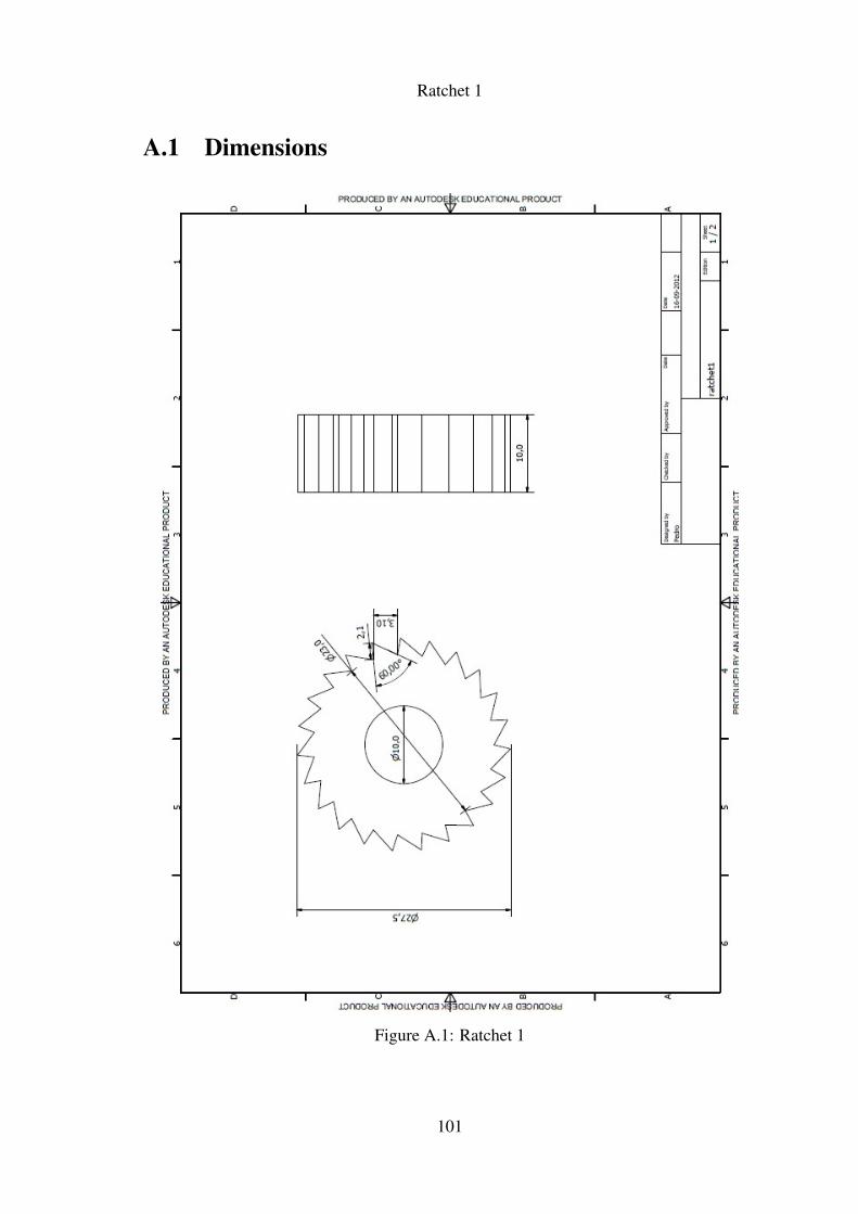
Ratchet 1
A.1 Dimensions
Figure A.1: Ratchet 1
101
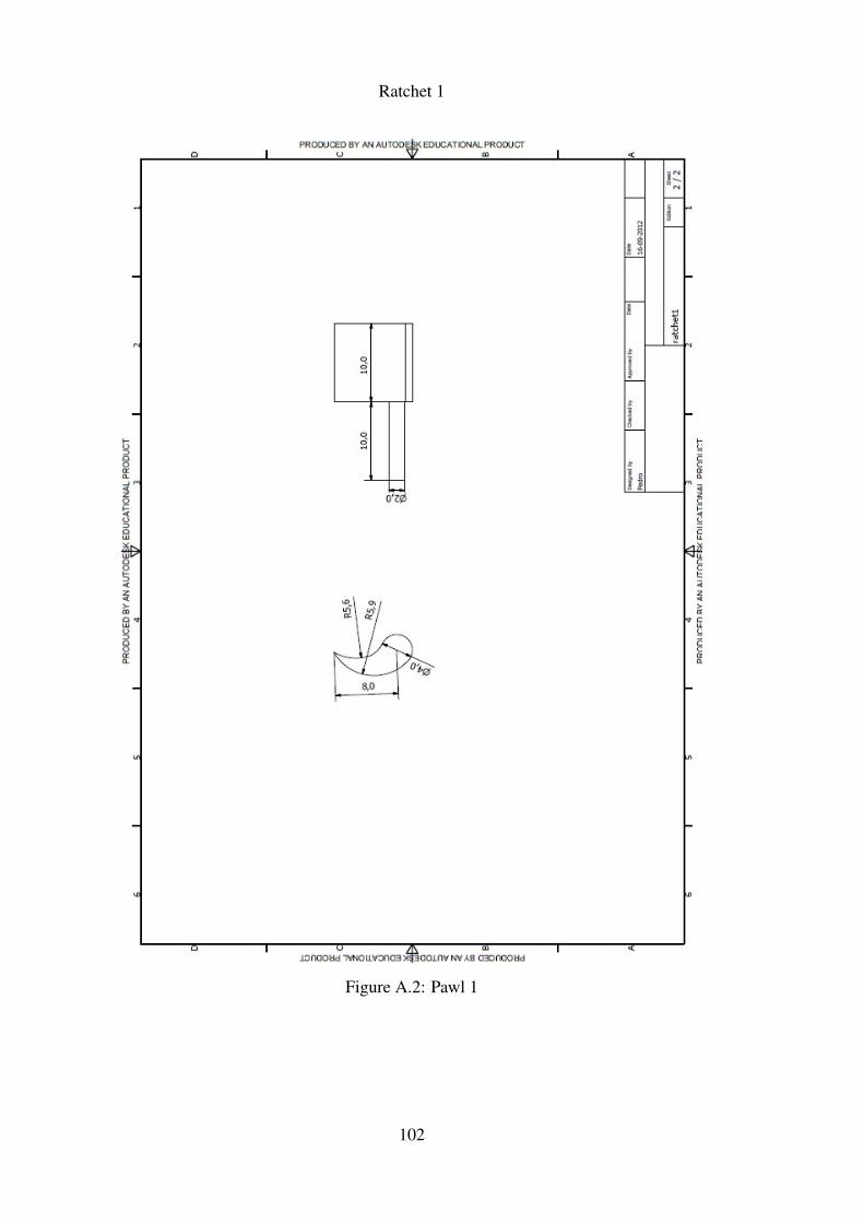
Ratchet 1
Figure A.2: Pawl 1
102
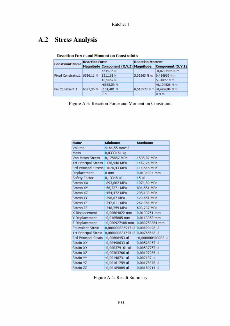
Ratchet 1
A.2 Stress Analysis
Figure A.3: Reaction Force and Moment on Constraints
Figure A.4: Result Summary
103

Ratchet 1
104

Appendix B
Ratchet 2
105

Ratchet 2
106
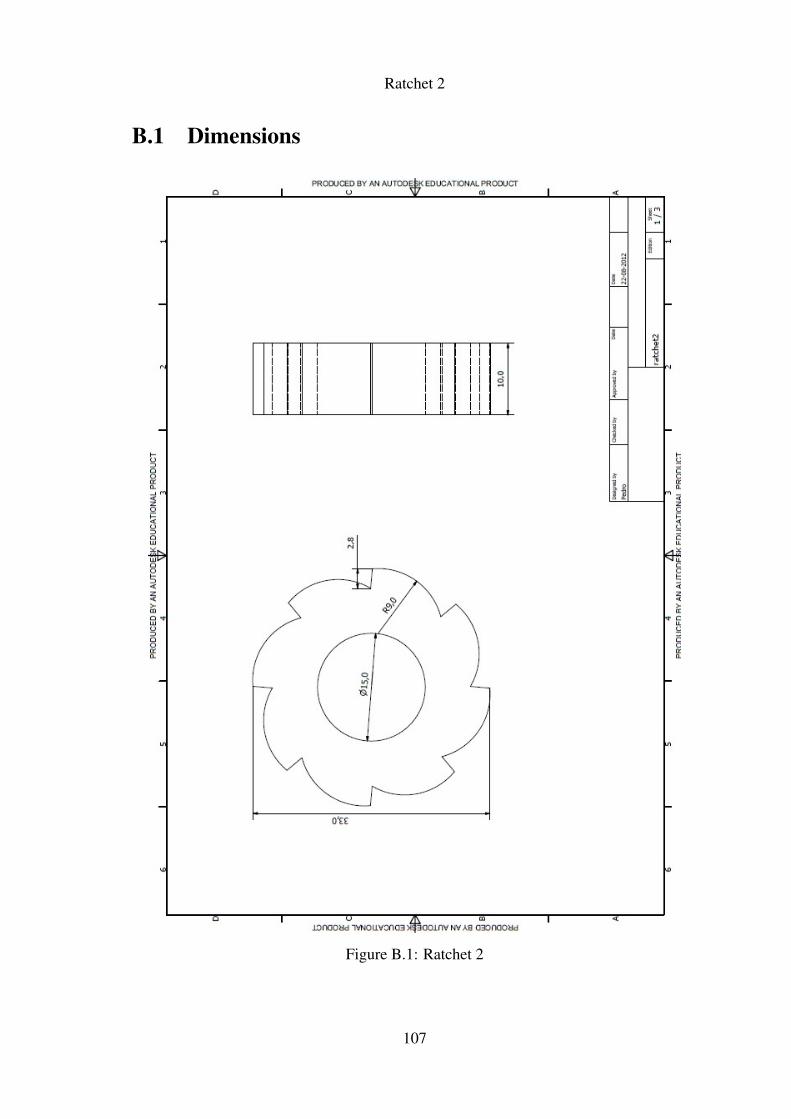
Ratchet 2
B.1 Dimensions
Figure B.1: Ratchet 2
107
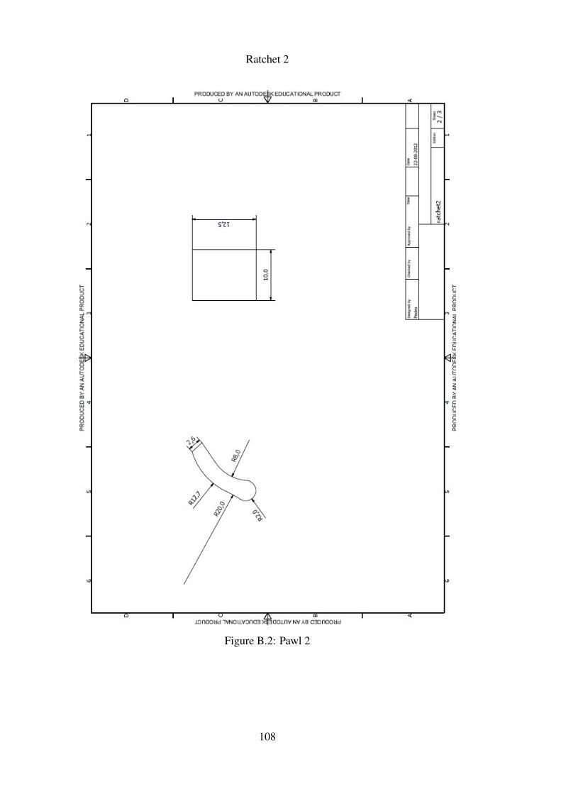
Ratchet 2
Figure B.2: Pawl 2
108
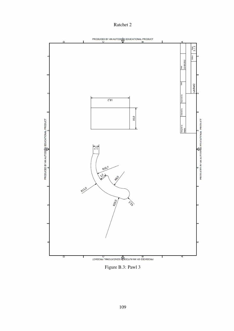
Ratchet 2
Figure B.3: Pawl 3
109
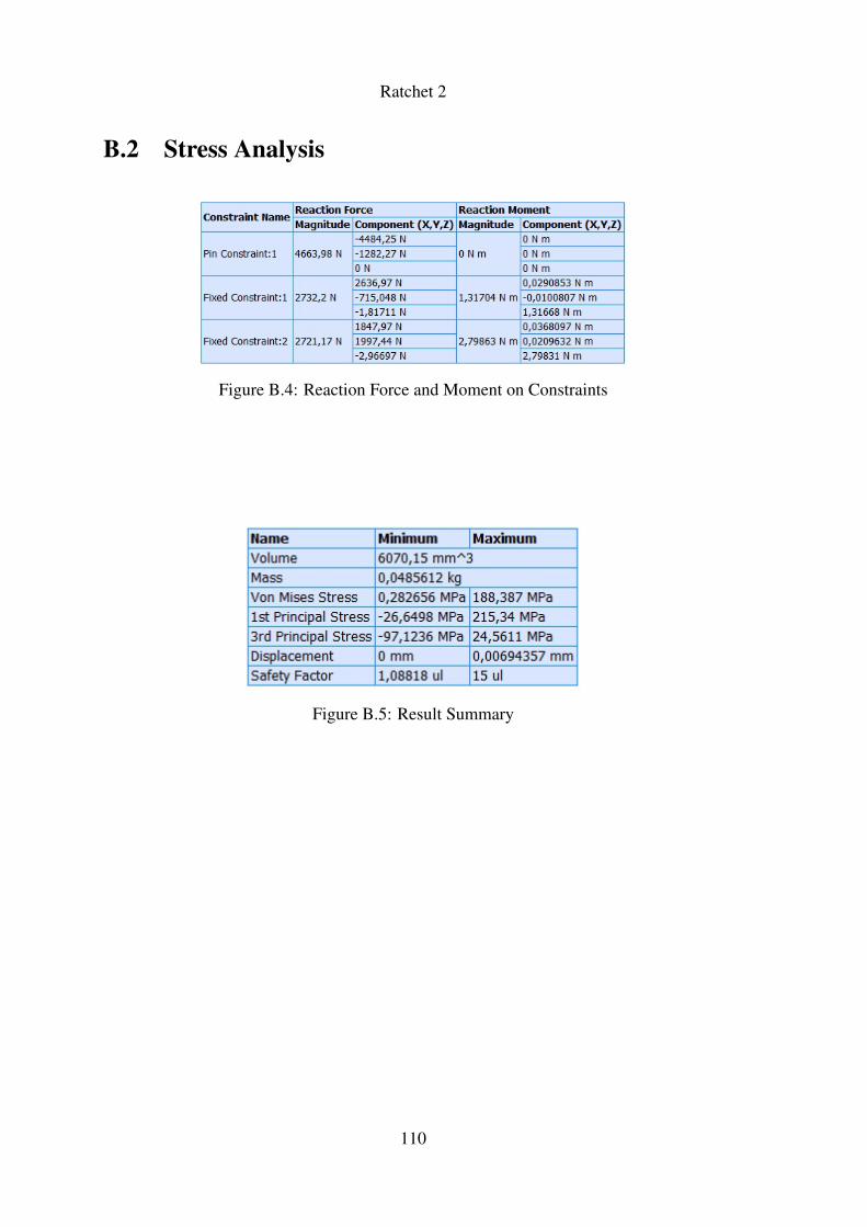
Ratchet 2
B.2 Stress Analysis
Figure B.4: Reaction Force and Moment on Constraints
Figure B.5: Result Summary
110

Appendix C
Slot Mechanism
111

Slot Mechanism
112
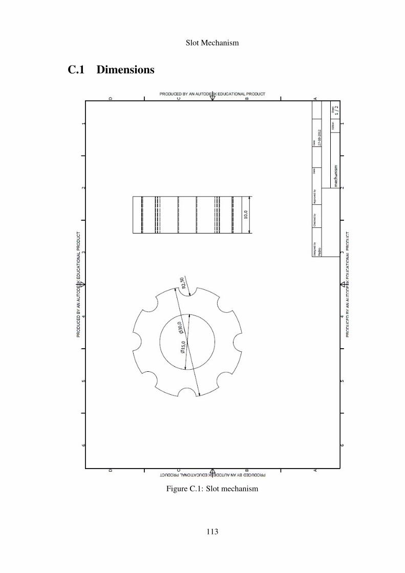
Slot Mechanism
C.1 Dimensions
Figure C.1: Slot mechanism
113
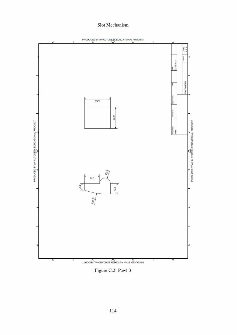
Slot Mechanism
Figure C.2: Pawl 3
114
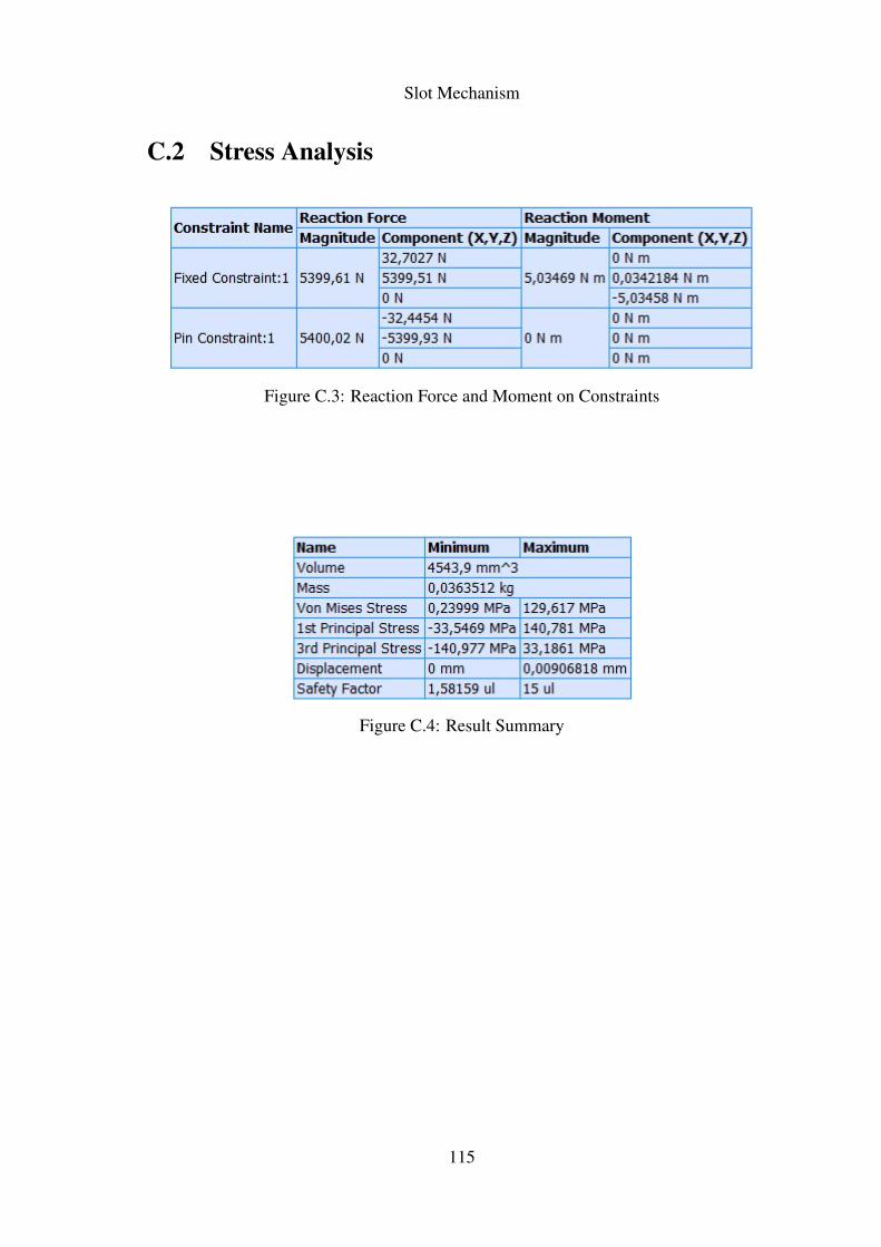
Slot Mechanism
C.2 Stress Analysis
Figure C.3: Reaction Force and Moment on Constraints
Figure C.4: Result Summary
115

Slot Mechanism
116

Appendix D
Generic Mechanism
117

Generic Mechanism
118
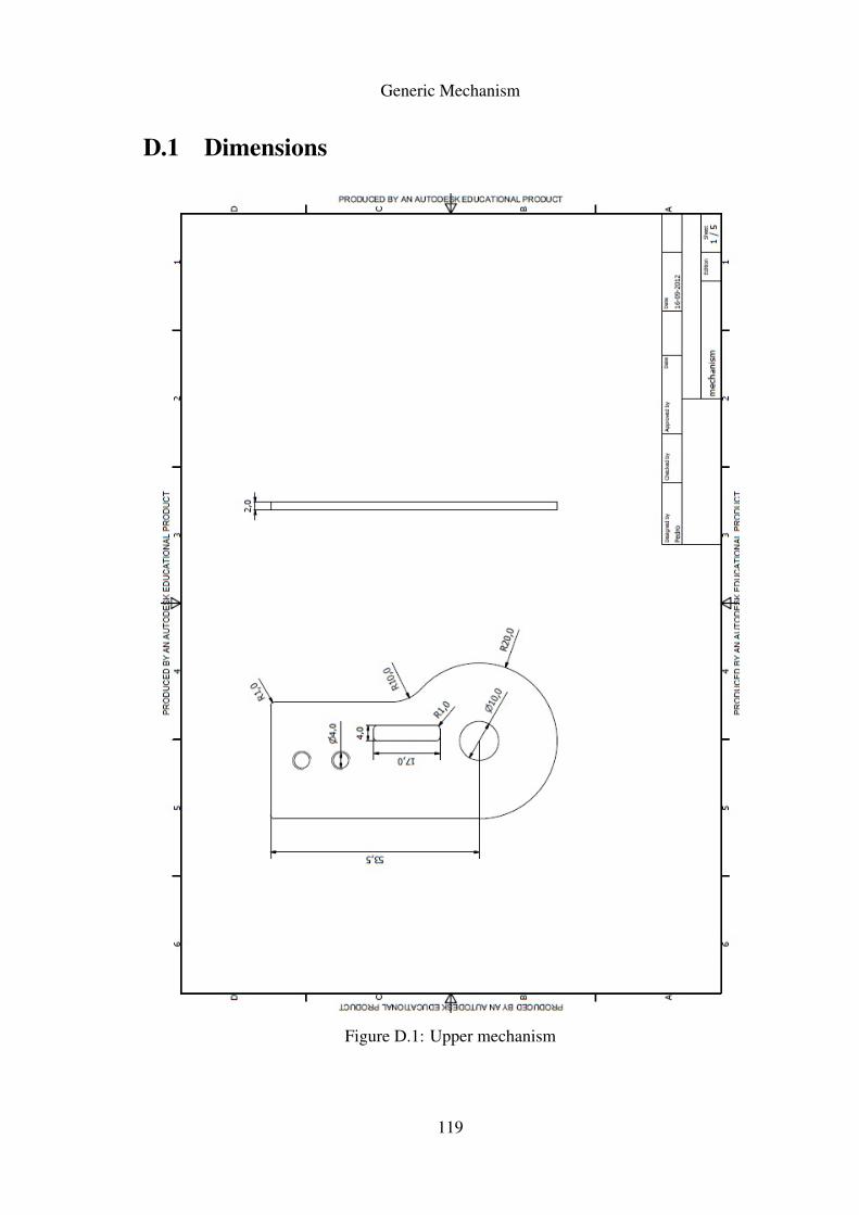
Generic Mechanism
D.1 Dimensions
Figure D.1: Upper mechanism
119
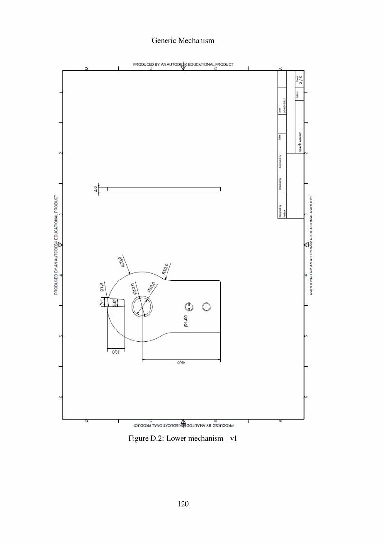
Generic Mechanism
Figure D.2: Lower mechanism - v1
120
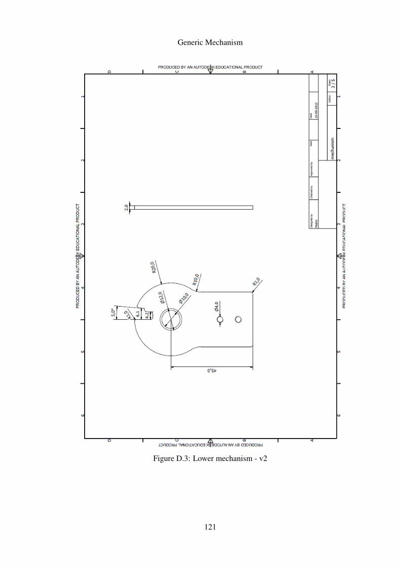
Generic Mechanism
Figure D.3: Lower mechanism - v2
121
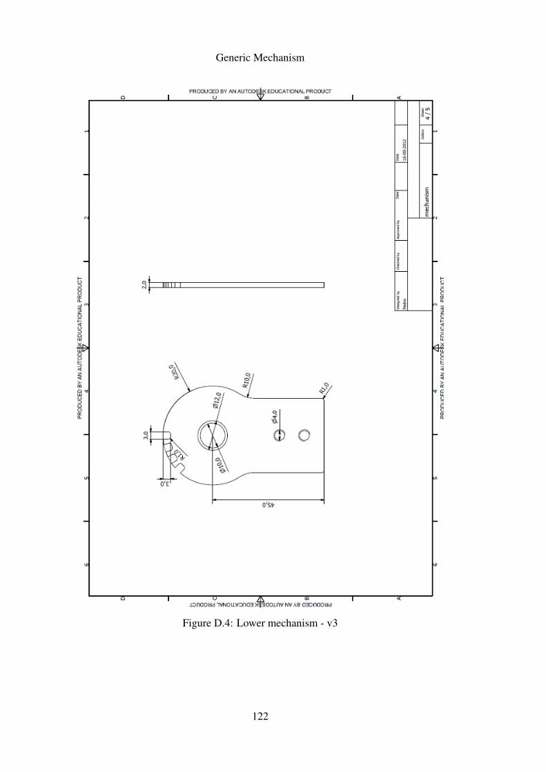
Generic Mechanism
Figure D.4: Lower mechanism - v3
122
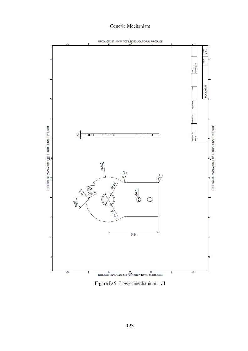
Generic Mechanism
Figure D.5: Lower mechanism - v4
123

Generic Mechanism
124

Appendix E
Schematics
125

Schematics
126
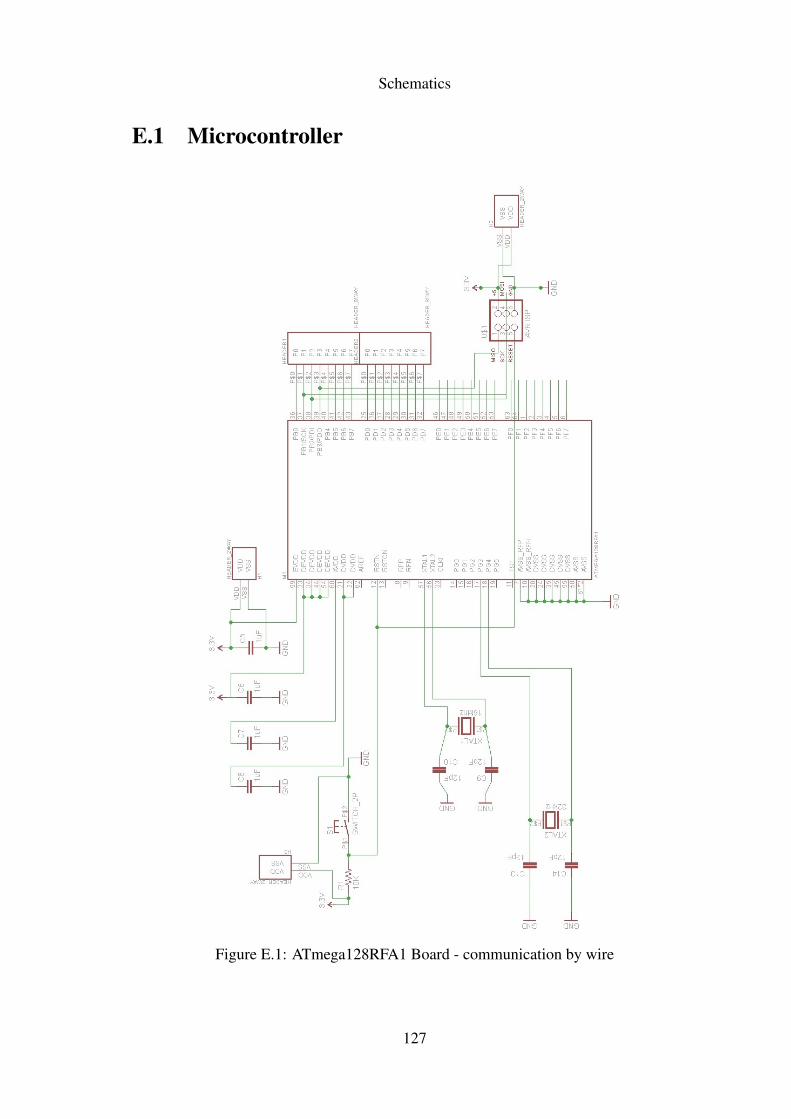
Schematics
E.1 Microcontroller
Figure E.1: ATmega128RFA1 Board - communication by wire
127
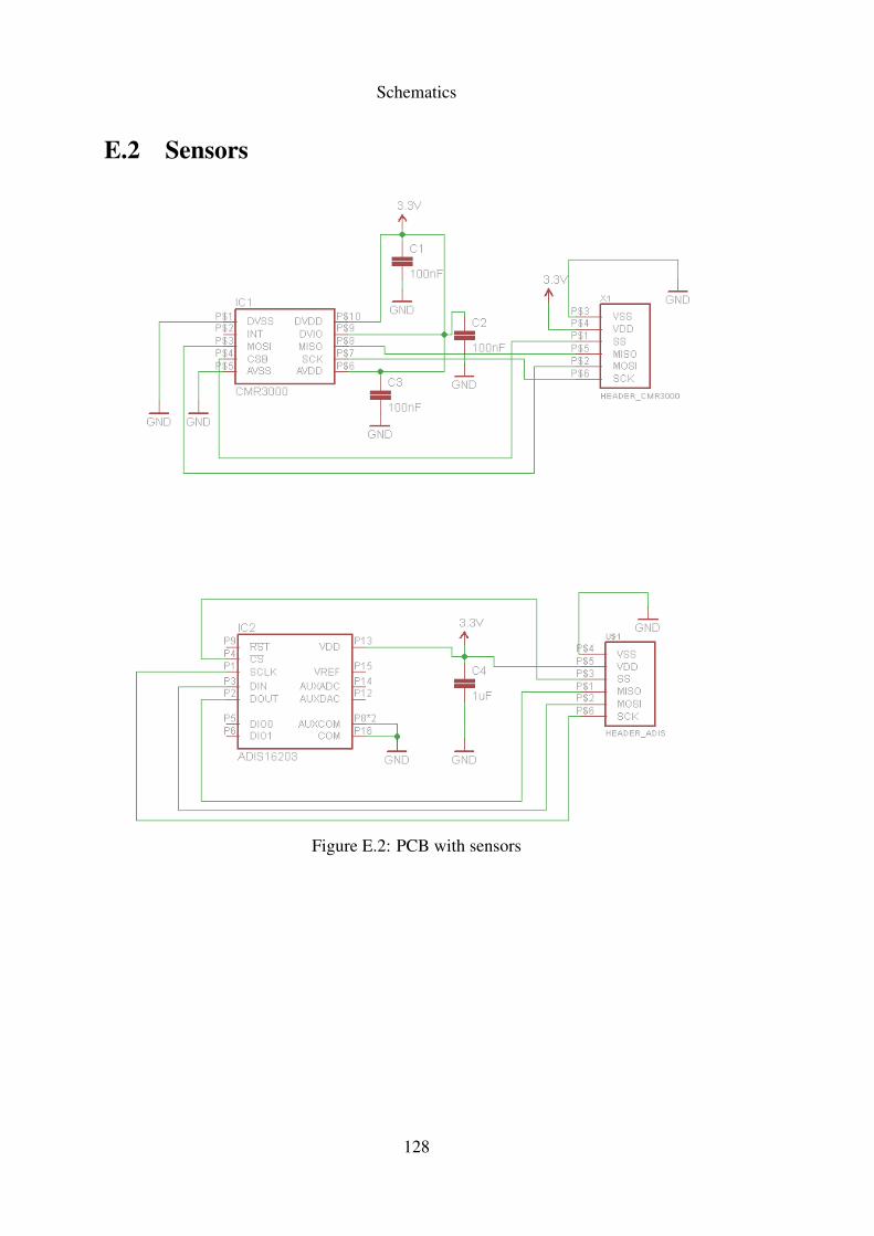
Schematics
E.2 Sensors
Figure E.2: PCB with sensors
128
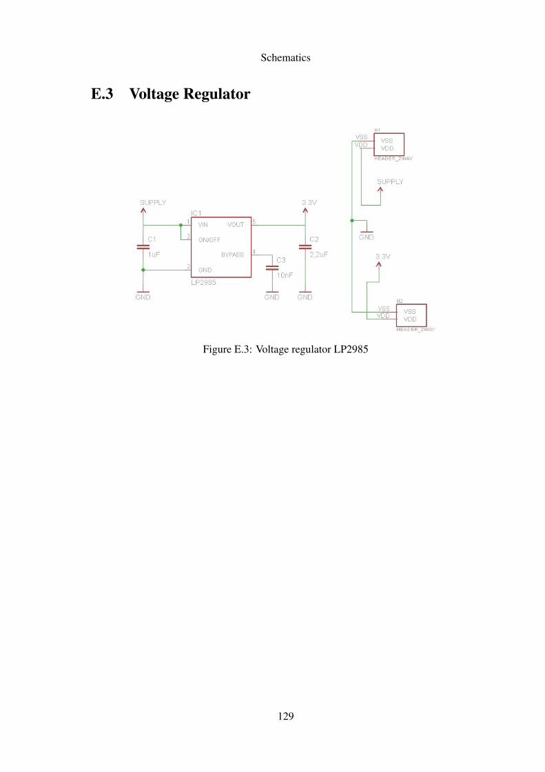
Schematics
E.3 Voltage Regulator
Figure E.3: Voltage regulator LP2985
129