Embed Size (px)
Citation preview

7º FÓRUM DE TURBOMÁQUINAS PETROBRAS Rio de Janeiro – 24 a 26 de novembro de 2009
Stable dry low emission combustion with fuel flexibility
Bengt Gudmundsson (Siemens Industrial Turbomachinery AB) [email protected] Larfeldt (Siemens Industrial Turbomachinery AB) [email protected]
Abstract
With an experience over 6 million operating hours the Siemens DLE system for 15 - 50 MW gas turbines has proven to have the same availability and operational stability as conventional combustion systems. Critical factors to control in a reliable combustion system are long term combustion stability over the whole load range with different ambient conditions, ability of rapid load changes, combustor life time, and fuel flexibility.
1. Introduction Plant profitability and low environmental impact are of key importance for oil and gas companies. If a plant includes a gas turbine installation these factors are influenced by the gas turbine characteristics such as availability, emission levels and maintenance intervals. One gas turbine component with an impact on all these factors is the combustion system. To decrease the emission levels of both CO and NOx to required levels a number of technologies such as water injection, steam injection and dry low emission combustion systems are currently utilized. The dry low emission (DLE) systems are preferred since the system complexity is reduced by eliminating water treatment and auxiliaries to handle the water or steam injection.
The market perception is that dry low emission systems are less flexible, less reliable and require more maintenance than conventional combustion systems. However, with an experience over 6 million operating hours the Siemens DLE system have proven to have the same availability and operational stability as conventional combustion systems. Furthermore, recent developments have also improved the fuel flexibility of the DLE system and reduced the need for complex and expensive fuel treatment systems. This paper covers the DLE development and current status for the Siemens gas turbines SGT-600 (25 MWel) [1], SGT-700 (31 MWel) [2], and SGT-800 (47 MWel) [3]. 2. Dry low emissions for O&G
The 2nd generation dry low emission burner was developed to meet the increased emissions requirements for the on-shore market. It was introduced in the SGT-600 25 MW gas turbine in 1991 (figure 1). The SGT-600 system is capable of emission levels as low as 25 ppm NOx using natural gas fuel. For liquid fuel water injection as in the conventional case is still used to lower the flame temperature and achieve emission levels as low as 42 ppm NOx [4].The burner is a split cone with two main fuel pipes. The compressor air enters in the two slots where also main fuel is injected from the main fuel pipes perpendicular to the air flow in order to achieve mixing. The injection of pilot gaseous fuel as well as main liquid fuel is positioned in the center of the burner.
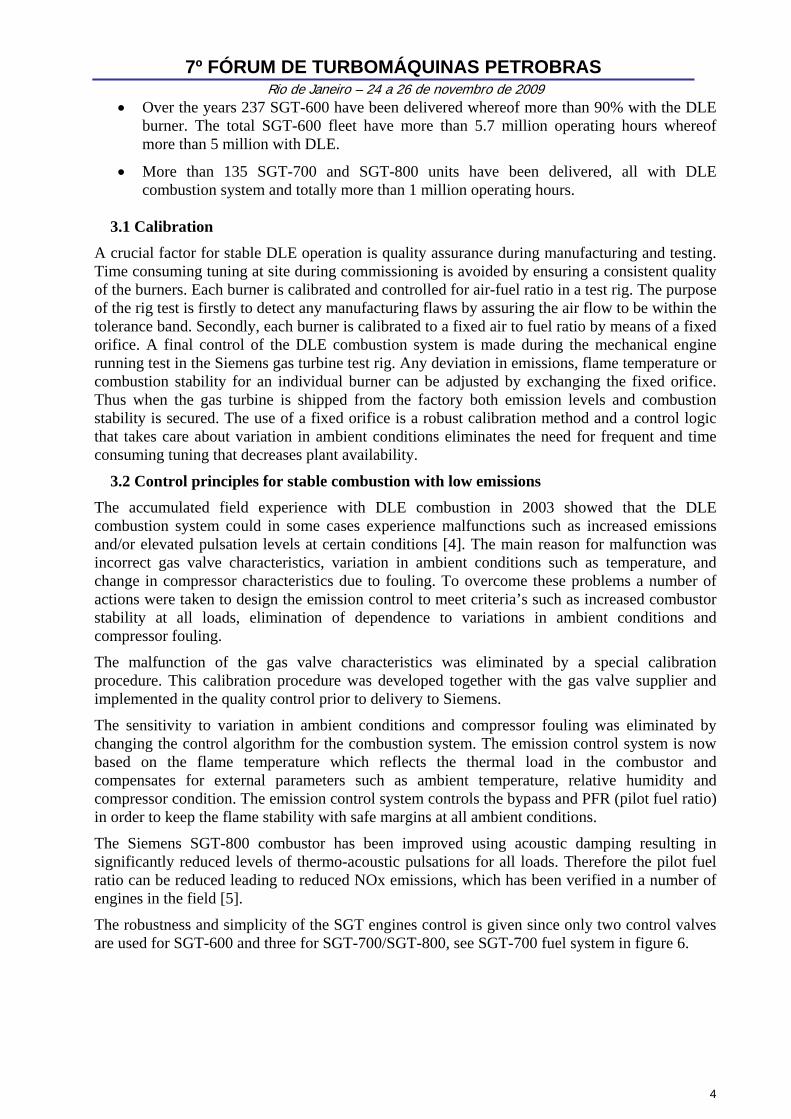
During the development of SGT-700 and SGT-800 in the mid 1990’s DLE technology was brought one step further. By using the experience from the 2nd generation technology the idea was to decrease NOx emissions further with natural gas fuel and create a burner that can deliver low emissions also with liquid fuel. The 3rd generation DLE system was successfully verified tested during the SGT-800 first fire in 1998. The DLE system delivers 15 ppm NOx emissions on natural gas and 42 ppm NOx on liquid fuel. This burner consist of a split cone forming four air slots where main gas is injected followed by a mixing section with film air holes (figure 2). Near

7º FÓRUM DE TURBOMÁQUINAS PETROBRAS Rio de Janeiro – 24 a 26 de novembro de 2009
the base of the cone central gas and main liquid is fed and intensively mixed with the compressor air. The pilot fuel injection is positioned at the burner tip.
Figure 1. The 2nd generation burner used in SGT-600 DLE.
Figure 2. The 3rd generation burner for SGT-700 and SGT-800.
2.1 Emissions on part load
Gas turbine installations in O&G applications are often operating at part load and in island mode. This is due to the fact that the design point often is at a high ambient temperature to guarantee the production rate also during hot periods. Additional power margin is often added and sometimes also a running standby gas turbine. Consequently the DLE system must be capable of stable combustion and low emissions also at part load.
To achieve the optimum emissions and low pulsation levels it is of key importance to control the flame temperature and stability in the combustor. As illustrated in figure 3 the concentration of NOx is decreasing with decreasing flame temperature but on the other hand the formation of CO increases. Therefore, there is an optimum temperature window where NOx and CO are kept at a minimum level. The combustion becomes too lean as the load is decreased and usually a pilot flame is used to maintain the flame at lower loads. Combustion stability can also be improved by reducing the air to fuel ratio. This can be achieved by combustor by-pass and compressor bleed.
The expected emissions levels versus load for SGT-700 are illustrated in figure 4. The combustor by-pass is utilized between 70 and 90% load to maintain the flame temperature by a reduced air flow through the burners. Consequently the CO in the exhaust gas is kept at a low level. The combustor bypass system, as illustrated in figure 5, is integrated with the turbine casing and consists of 6 valves controlled by one actuator. The pilot flame is running in a diffusion mode and as the PFR increase the NOx levels increase. The combustion stability and emissions are kept at low levels over the load range by only two parameters, namely pilot fuel ratio and bypass opening. To achieve low CO emissions even below 60% load the flame temperature can be maintained at an optimum level by utilizing compressor bleed, either to the inlet or the exhaust (figure 4). At really low load the air to fuel ratio is such that combustion is incomplete with high CO levels as a result.
2

7º FÓRUM DE TURBOMÁQUINAS PETROBRAS Rio de Janeiro – 24 a 26 de novembro de 2009
Flame temperature [K]
CO [
ppm
at
15%
O2]
NOx [ppm
at 15% O
2]
CONOx
Variable
Desired Range of Operation
Load [%]
CO [
ppm
at
15%
O2]
NOx [ppm
at 15% O
2]
100806040200
200
150
100
50
0
30
25
20
15
10
5
0
NOxCO w BleedCO expected
Variable
Compressor Bleed
Combustion Bypass
Figure 3. Typical behavior of NOx and CO versus flame temperature.
Figure 4. Expected emissions for SGT-700 with bypass operation indicated as well as standard bleed in operation.
Figure 5. SGT-600 bypass system used to keep the flame temperature constant between 70 and 100 % load.
3. Meeting O&G Requirements on Operational Stability The target for a lower global environmental impact makes DLE systems an attractive solution in comparison to the conventional combustion systems. As mentioned above, the current market perception is that the DLE systems are less reliable than conventional systems. Siemens DLE systems with a service interval of 30 000h have more than 6 million accumulated operating hours and a reliability of 99% or better. The corresponding availability is 97% based on a concept with maintenance at site. If the customer selects a gas generator exchange the availability can be increased by at least 1% to 98% or better. One key parameter to the high reliability numbers is the DLE system stability.
3
7º FÓRUM DE TURBOMÁQUINAS PETROBRAS Rio de Janeiro – 24 a 26 de novembro de 2009
• Over the years 237 SGT-600 have been delivered whereof more than 90% with the DLE burner. The total SGT-600 fleet have more than 5.7 million operating hours whereof more than 5 million with DLE.
• More than 135 SGT-700 and SGT-800 units have been delivered, all with DLE combustion system and totally more than 1 million operating hours.
3.1 Calibration
A crucial factor for stable DLE operation is quality assurance during manufacturing and testing. Time consuming tuning at site during commissioning is avoided by ensuring a consistent quality of the burners. Each burner is calibrated and controlled for air-fuel ratio in a test rig. The purpose of the rig test is firstly to detect any manufacturing flaws by assuring the air flow to be within the tolerance band. Secondly, each burner is calibrated to a fixed air to fuel ratio by means of a fixed orifice. A final control of the DLE combustion system is made during the mechanical engine running test in the Siemens gas turbine test rig. Any deviation in emissions, flame temperature or combustion stability for an individual burner can be adjusted by exchanging the fixed orifice. Thus when the gas turbine is shipped from the factory both emission levels and combustion stability is secured. The use of a fixed orifice is a robust calibration method and a control logic that takes care about variation in ambient conditions eliminates the need for frequent and time consuming tuning that decreases plant availability.
3.2 Control principles for stable combustion with low emissions The accumulated field experience with DLE combustion in 2003 showed that the DLE combustion system could in some cases experience malfunctions such as increased emissions and/or elevated pulsation levels at certain conditions [4]. The main reason for malfunction was incorrect gas valve characteristics, variation in ambient conditions such as temperature, and change in compressor characteristics due to fouling. To overcome these problems a number of actions were taken to design the emission control to meet criteria’s such as increased combustor stability at all loads, elimination of dependence to variations in ambient conditions and compressor fouling.
The malfunction of the gas valve characteristics was eliminated by a special calibration procedure. This calibration procedure was developed together with the gas valve supplier and implemented in the quality control prior to delivery to Siemens.
The sensitivity to variation in ambient conditions and compressor fouling was eliminated by changing the control algorithm for the combustion system. The emission control system is now based on the flame temperature which reflects the thermal load in the combustor and compensates for external parameters such as ambient temperature, relative humidity and compressor condition. The emission control system controls the bypass and PFR (pilot fuel ratio) in order to keep the flame stability with safe margins at all ambient conditions.
The Siemens SGT-800 combustor has been improved using acoustic damping resulting in significantly reduced levels of thermo-acoustic pulsations for all loads. Therefore the pilot fuel ratio can be reduced leading to reduced NOx emissions, which has been verified in a number of engines in the field [5].
The robustness and simplicity of the SGT engines control is given since only two control valves are used for SGT-600 and three for SGT-700/SGT-800, see SGT-700 fuel system in figure 6.
4

7º FÓRUM DE TURBOMÁQUINAS PETROBRAS Rio de Janeiro – 24 a 26 de novembro de 2009
Figure 6. SGT-700 fuel system with three control valves used for governing operation. The fuel is distributed to the burners by manifolds.
3.3 Dual fuel operation The ability to operate on both liquid and gas fuel is crucial in many applications. In case there is a lack of gas fuel the gas turbine should be able to operate on liquid as back up fuel to secure the production. One example is production systems that are depending on diesel fuel before the gas or oil field is established. Another example is when the gas turbine is operating on the process gas and a back liquid fuel is needed if the gas process is interrupted intentionally or due to malfunction. In the latter case it is important that the switch over from gas to liquid or vice versa can be made automatically during operation. Otherwise the production has to be interrupted for every instance there is a process malfunction. All Siemens dual fuel DLE systems are capable of switching between gas and liquid or vice versa during operation. Below is an example of a SGT-600 operating on process gas in a gas/oil field on the North Sea. If there is any sign of process abnormalities such as a large change in gas pressure or gas temperature the gas turbine is automatically switching over to operate on diesel as shown in figure 7. There are two gas turbines in operation during the fuel switch over and due to load sharing the grid frequency is kept constant during the switch over and the load swing is moderate about 1 MW for the gas turbine that is switching fuel. Once the process is stabilized the gas turbine will switch over and operate on gas fuel again. The time for fuel switch over is in the range of 30 seconds.
5

7º FÓRUM DE TURBOMÁQUINAS PETROBRAS Rio de Janeiro – 24 a 26 de novembro de 2009
Time
Pow
er [
MW
el]
Fuel
flo
w a
nd F
requ
ency
[M
J/s
and
Hz]
18:35:0518:35:0018:34:5518:34:5018:34:4518:34:4018:34:35
35
30
25
20
15
10
5
0
50
40
30
20
10
0
LoadLiquidGaseousFrequency
Variable
change overMW during fuelLoad swing about 1
Figure 7. Example of fuel change over from gas to liquid in SGT-600 in about 30 seconds resulting in a slight load increase of about 1 MW.
3.4 Load changes and load rejection
The ability to handle rapid load changes and load rejections is also an important factor to increase plant productivity. A gas turbine trip or a slow response during load changes is detrimental to plant productivity. In many cases the gas turbines are operating in island mode and have to cope with starting of large power objects. The requirement when starting large power objects is a quick response and a minimum frequency drop during the switchover. The response and frequency drop is determined by a number of factors as the combustor capability, power turbine response, automatic voltage control (AVC), compressor surge limit and the rated power of the object. All Siemens DLE systems have a simple control algorithm and the number of burners is relatively few and easy to synchronize due to the fact they are all controlled by the same control valve distributing the fuel in the fuel manifolds. A load step from 0 MW to 9 MW with the SGT-700 gas turbine is shown in figure 8. The initial fluctuation in power is mainly due to the AVC and the decrease down to 8.5 MW is due to reduced resistance induced by heating of the load banks.
In case of a load rejection the plant productivity can be maintained if the gas turbine just goes down to idle without tripping. One example is shown in figure 9 demonstrating a load rejection from 30 MW to 0 MW without tripping the gas turbine. As shown the gas turbine goes down to idle after the 30 MW load rejection and is ready to deliver power when the production requires.
4 Fuel flexibility of the DLE systems The gas turbine ability to burn a variety of fuel qualities can improve plant profitability since the need for complex and expensive fuel treatment and/or flaring can be avoided. Siemens have recently started to explore the capability of their DLE systems and below follows two examples where the DLE system has proven to have a large potential. The first example is fuels with high contents of inert gas which is sometimes the case in end flash gases in LNG plants. The second example is related to fuels with high contents of heavy hydrocarbons which can be the case in associated gases or in gas treatment plants.
6

7º FÓRUM DE TURBOMÁQUINAS PETROBRAS Rio de Janeiro – 24 a 26 de novembro de 2009
Time [sec]
Po
wer
[M
Wel
]
Ro
tating
Sp
eed [rp
m]
35302520151050
14
12
10
8
6
4
2
0
7000
6000
5000
4000
3000
2000
1000
0
Power Turbine SpeedPower
Variable
Time [sec]
Po
wer
[M
Wel
]
Ro
tating
Sp
eed [rp
m]
706050403020100
40
30
20
10
0
10000
8000
6000
4000
2000
0
Gas Generator SpeedPower Turbine SpeedPower
Variable
Figure 8. Gas turbine response to a 9 MW load step from idle. The drop in power to 8.5 MW is due to decreased resistance in the load banks induced by heating.
Figure 9. The rotating of speed of gas generator and power turbine and engine load versus time during a SGT-700 transient test 27 April 2006. The power drops from 30 to 0 MW.
4.1 Gaseous fuel with high contents of inert gas
There are a number of applications where the need to burn gas with high contents of inert gas such as nitrogen or carbon dioxide. One example is in LNG production where the end flash gas will contain up to eight times higher nitrogen content than the feed gas. From a production economy point of view it is desirable to use the end flash gas as gas turbine fuel. The ideal situation is if the end flash gas can be used without an expensive and complex nitrogen rejection unit. Recently full scale engine tests were carried out on the SGT-700 and SGT-800 to prove their ability to operate on fuel gases with nitrogen content as high as 50 vol-%.
A standard SGT-700 with a standard gas-fuel system was used in the test. Different loads over the whole load range were tested and the nitrogen content varied between 0 and 40 vol-%. Figure 10 shows the gradual increase of nitrogen in the fuel gas up to 40 vol-% for the 20 MW load case. The 20 MW load was maintained during the whole test and after approximately 43 minutes the nitrogen feed to the natural gas was closed rapidly to verify the transient capabilities of the combustion system. This transient corresponds to an increase of the Wobbe Index by 80% in 2 minutes. The pilot fuel ratio (PFR) was adjusted for 40 vol-% Nitrogen and, therefore, the NOx level decrease as the nitrogen content is increased during the test. When the nitrogen is switched off the NOx level increase and after this the PFR is adjusted manually for pure natural gas and the NOx level decrease to 15 ppm. The PFR adjustment can be automized without a need of a calorimeter if the fuel composition during start of the gas turbine is known. The stability was also proven at 6 and 27 MW, with no limiting indications noted. The emission levels during the test were in the same range as operation on pure natural gas. Since combustion was very stable the resulting emission levels were also stable.
In June 2009 a similar test was carried out on the SGT-800 with a standard DLE system. During this test the machine was operating successfully on fuel gas with a nitrogen dilution as high as 50 vol-%.
7

7º FÓRUM DE TURBOMÁQUINAS PETROBRAS Rio de Janeiro – 24 a 26 de novembro de 2009
Time [minutes]
N2 c
once
nt [
vol%
] an
d NO
x [p
pm]
Load [%] and LFP [m
bar]
50403020100
40
30
20
10
0
100
80
60
40
20
0
N2NOxLFPLoad
Variable
reduce the LFPCentral gas adjusted to
Figure 10. Nitrogen content in vol-% and NOx emissions in ppm (left axis) and load and low frequency pulsations (LFP) (right axis) versus time during SGT-700 engine test with nitrogen feeding in natural gas at 20 MW (approximately 60% load) on 19th of August 2008.
4.2 Gaseous fuel with high contents of heavy hydrocarbons
In up stream applications and in gas processing plants the concentration of heavy hydrocarbons in the fuel can be high. The main concern is auto ignition of the heavy hydrocarbons due to their low ignition temperature. The current fuel specification for SGT-600, SGT-700 and SGT-800 limits the amount of butane and higher to 6 vol-%. The industrial gas turbines have a relatively moderate compression ratio and hence the temperature of the air after the compressor is moderate. Recent calculations show that the DLE system can burn much higher concentrations of heavy hydrocarbons due to the moderate air temperature in combination with a stable DLE system. During autumn 2008 a successful atmospheric test was conducted with pentane concentrations as high as 20 vol-%. The current plan is to further explore the capability of high concentrations of pentane in a full scale engine test scheduled in spring 2010.
5. Conclusion
The DLE system for the SGT-600, SGT-700 and SGT-800 gas turbines fulfills the requirements of a flexible and stable combustion system for oil and gas applications. Both reliability, 99%+ and availability 97%+ are in the same order of magnitude as engines with conventional combustion systems not taking a core engine exchange programs into account. The operational stability and emission levels both at full and part load as well as the fuel flexibility are excellent.
6. References
1. Detailed Hot Section Mapping of Siemens SGT-600, Sundberg J. and Blomstedt M., PowerGen, Milan, June 2008.
2. Siemens SGT-700 gas turbine performance upgrade yields more power and higher efficiency, A. Hellberg and G. Norden, Power-gen Europe 2009, Cologne, Germany.
3. Siemens SGT-800 industrial gas turbine enhanced to 47 MW. Design modifications and operation experience, S. Shukin et al, ASME conference Power for Land, Sea and Air, 2008 Berlin, Germany.
4. GT10B 2nd Generation DLE combustion Chamber Field Experience, Blomstedt M., Navrotsky V. and Lindman O., Power Gen Asia, Bangkok, October 5th 2004.
5. Emissions reduction and cooling improvements due to the introduction of passive acoustic damping in an existing SGT-800 combustor, D. Lörstad, J. Pettersson and A. Lindholm, GT2009-593131, ASME TE09, Orlando, 2009.
8