Embed Size (px)
Citation preview

www.kometgroup.com
KOMET GROUP GmbH Zeppelinstraße 3 · 74354 BesigheimTel. +49 7143 3730 · Fax +49 7143 373233 · [email protected]
KOMET do Brasil Ltda.Rua Brasileira, 439 · 07043-010 Guarulhos - São PauloTel. +55 11 24235502 · Fax +55 11 24220069 [email protected]
KOMET GROUP OF CHINANo. 5 Schaeffler Road Taicang, Jiangsu Province, PRC 215400Tel. +86 512 53575758 · Fax +86 512 [email protected]
KOMET S.à.r.l.46-48 Chemin de la Bruyère · 69574 Dardilly CEDEXTel. +33(0) 4 37 46 09 00 · Fax +33(0) 4 78 35 36 57 · [email protected]
KOMET (UK) Ltd.4 Hamel House · Calico Business Park · Tamworth · B77 4BFTel. +44(0)1827.302518 · Fax +44(0)1827.300486 · [email protected]
KOMET Precision Tools India Pvt. Ltd. 16J, Attibele Industrial Area · BANGALORE - 562 107Tel. +91 80 2807 8000 · Fax +91 80 2807 [email protected]
KOMET Utensili S.R.L.Via Massimo Gorki n. 11 · 20098 S. Giuliano Mil.Tel. +39 02 98 40 28 1 · Fax +39 02 98 44 96 2 · [email protected]
KOMET GROUP KK# 180-0006 · 1-22-2 Naka-cho Musashino-shi Tokyo Japan · Grand Preo Musashino 203 Tel. +81(0)422 50 0682 · Fax +81(0)422 50 [email protected]
KOMET de México S. de R. L. de C.VAcceso 1 Nave 8 No. 116 · Fraccionamiento Industrial La MontañaQuerétaro, Qro. C.P 76150 MéxicoTel. +52 442 2109020 · Fax +52 442 [email protected]
KOMET GROUP GmbHZeppelinstraße 3 · D-74354 BesigheimTel. +43 512 28355932 · Fax +43 512 28355999 · [email protected]
KOMET-URPOL Sp. z o.o ul. Przyjaźni 47 b · PL 47-225 Kędzierzyn-KoźleTel. +48 77 405 31 00 · Fax +48 77 405 31 10 · [email protected]
KOMET GROUP GmbHZeppelinstraße 3 · D-74354 BesigheimTel. +49 7143 3730 · Fax +49 7143 373233 · [email protected]
KOMET of America, Inc.2050 Mitchell Blvd. · Schaumburg · IL 60193-4544Tel. +1 (8 47) 9 23 / 84 00 · +1 (8 47) 9 23 / 84 80Fax +1 (8 00) 8 65 / 66 [email protected]
KOMET Scandinavia ABBox 9177 · SE-200 39 MalmöTel. +46 40 49 28 40 · Fax +46 40 49 19 95 · [email protected]
KOMET IBERICA TOOLS S.L.Av. Corts Catalanes 9-11 · Planta baja, local 6B · 08173 Sant Cugat Del VallesTel. +34 93 5839620 · Fax +34 93 5839612 · [email protected]
KOMET GROUP GmbH ul. M.Salimganova 2V · 420107, Kazan Tel. +7 843 5704345 · Fax +7 843 2917543 · [email protected]
KOMET of CANADA Tooling Solutions ULC250 Harry Walker Parkway N · Unit 6B, Newmarket, Ontario, L3Y 7B4Tel. +1 905 9540466 · Fax +1 905 [email protected]
KOMET GROUP Precision Tools Korea Co., Ltd.#201, Lotte IT Castle-2, 550-1, Gasan-dong, Geumcheon-gu, Seoul, 153-768Tel. +82(0)2.2082-6300 · Fax +82(0)[email protected]
KOMET GROUP CZ s.r.o.Na Hůrce 1041/2, 160 00 Praha 6Tel. +420 235010010 · Fax +420 235311890 · [email protected]
KOMET KESICI TAKIMLAR SAN VE TIC LTD STIYenikoy Mahallesi Koybasi cad. · Akbas Sokak no 7 Sariyer ISTANBULTel. +90 212 346 01 34 · Tel. +90 212 346 01 70 · Fax +90 212 346 01 64 · [email protected]
KOMET GROUP Precision Tools (Thailand) Co.,Ltd. 1558/61 Soi BaanKlangKrung 11, Bangna-Trad Road. Bangna, Bangkok 10260 Thailand
KOMET GROUP GmbH · Werk StuttgartRuppmannstraße 32 · 70565 Stuttgart-VaihingenTel. +49 711 788910 · Fax +49 711 7889111
399 01 004 04-2T-02/14 Printed in Germany www.wachter.de · © 2014 KOMET GROUP GmbH · We reserve the right to make modifications.
Ko
mPa
ss –
Mill
ing
KomPass – Milling
GerMany
France
china
Great Britain
india
italy
JaPan
Mexico
austria
Poland
switzerland
usa
sweden · denMarK · norway
sPain
russia
Brazil
canada
Korea
czech rePuBlic
turKey
southeast asia

2
KomPass Milling – Benefits for you
KOMet GROUP – MiLLinG expertise
The KOMET GROUP is recognised internationally as a
leader in innovation for high-precision drilling, reaming
and threading and, as such, sees itself as more than
simply a manufacturer of precision tools and rather as a
provider of innovative ideas – true to the company motto
“TOOLS PLUS IDEAS”.
Our extensive range of milling tools guarantees the
production of optimum surfaces in terms of quality and
performance. Thanks to maximum process reliability, our
tools form the basis for cost-effective production at our
customer sites.
special solutions for your milling operations – Greater range of functions, lower machining costs
Chapter 8

1
2
3
4
5
6
7
8
3
120 – 139
6 – 31
32 – 39
40 – 53
54 – 77
78 – 85
86 – 103
104 – 119
4 – 5Programme summary
informationsKOMET SERVICE®, KOMET® BRINKHAUS, Numerical Index
solid carbide milling cutter
nCD Composite milling cutter
PCD Milling cutter
indexable insert mills
Countersinking and chamfering
inserts
Mill adaptors

4
HSK-A 32 – HSK-A 100
ABS
25
– 1
00
6
E 116
x 12 x 25x 16 x 32x 20 x 36
M 5M 8M 10M 12M 16
HSK-A 50, 63, 100 HSK-A 50, 63, 100 HSK-A 32 – HSK-A 100
x 12 x 20x 16 x 25
ABS
25
– 1
00
x 6
– 3
2
x 6
– 3
2
x 1
6, 2
5, 3
2
x 1
6, 2
5, 3
2
x 6
– 3
2
x 3
– 3
2
ABS
50–
80
x 2
0, 2
5, 3
2
ABS
40–
63
x 6
– 3
2
ABS
32–
63
x 6
– 3
2
ABS
25–
100
ABS
25–
100
ABS
25
– 80
ABS
32–
100
ABS
25–
100
DIN 2079ISO 30ISO 40ISO 50
x 3
– 1
6
ABS
32–
100
Din 69871E 106 – 107
Jis B 6339 (MAs 403 Bt)E 108 – 109
E 114
E 115
ABS 50ABS 63ABS 80
HSK-A 50HSK-A 63HSK-A100
SK40SK50
BT30BT40BT50
ABS 80ABS100
E 110 – 111
E 112 – 113
HSK-A 63HSK-A100
HSK-A 63HSK-A100
HSK-A100
SK40SK50
BT40BT50
SK50
BT50
ABS 50ABS 63ABS 80ABS 100
Adaptors see catalogue "KomPass – Bore machining"
HsK-A Adaptors isO 12164-1with ABS® connection Adaptor sleeve Weldon
ABs® AdaptorsAdaptor sleeve Weldon
Programme summary
spindle adaptor flange
with ABS® connection
Extension
Reducer
Adaptors
Thermal expansion chuck
Thermal expansion chuck
Collet holder SZVExtension / Reducer
Expanding chuck
Expanding chuck
SK 40 – SK 50
with ABS® connection
taper shanks Din 69871
SK 40 / SK 50
Adaptor sleeve Weldon Thermal expansion chuckExpanding chuckSK 40 / SK 50
shrink fit technology
SK 40 / SK 50
Adaptorsfor screw-on milling cutter
Key
ABS® connection
Cylindrical connection
Weldon connection
Shrink connection
Screw connection
DIN 6357 adaptor
DIN 6358 adaptor
Milling cutter arbor FA
taper shanks fA
HsK-A Adaptors isO 12164-1
ABs® Adaptors
Combination milling cutter arbor FAK
taper shanks fA
Milling cutter arbor FACombination milling cutter arbor FAK

1
2
3
4
5
6
7
8
5
1
x 16x 20x 25x 32
x 9,5 – 40 mm E 66
x 16 x 25 x 19,6 / 27,6 mm E 68
x 16x 25x 32 x 17,5 – 47 mm E 69
x 25x 25 – 32 mm E 67
x 6 x 16x 8 x 18x 10 x 20x 12
E 13 – 14x 3 – 20 mm E 19
x 6 x 8 x 10 x 12x 16
x 3 – 16 mm E 17 – 18
x 6 x 8 x 10 x 12
x 6 – 12 mm E 22
x 6 x 14x 8 x 16x 10 x 18x 12 x 20
E 10 – 12x 3 – 20 mm E 19 – 20 E 25 – 27
x 6 x 14x 8 x 16x 10 x 18x 12 x 20
x 6 – 20 mm E 15
x 6 x 14x 8 x 16x 10 x 18x 12 x 20
x 3 – 20 mm E 16
x 6 x 8 x 10 x 12
x 6 – 12 mm E 23
x 8 x 10 x 12 x 16x 20
x 6 – 8 mm E 24
x 16x 25x 32
x 10 – 40 mm E 62
x 22x 27
x 63 / 80 mm E 64
x 16x 25x 32
x 20 – 32 mm E 70
x 27x 32
x 63 / 80 mm E 71
x 22x 27x 32x 40
x 40 – 125 mmE 72
x 16x 22x 27
x 40 – 93 mmE 73
x 16x 25x 32
x 10 – 48 mm E 80
x 6x 10
x 2 – 15 mm E 84
x 6,35
x 1 – 4 mm E 84
x 5x 10x 12
x 2 – 30 mm E 84x 6x 8x 10
x 2,5 – 25 mm E 85
x 5x 8x 12,5
x 8 – 20 mm E 85
HSK-A 63 x 40 – 160 mm E 47
3
4
x 22
Quatron hi.feed
x 52 mm E 58
M 10M 12M 16
Quatron hi.feed
x 20 – 42 mm E 58
x 20x 25x 32x 36
5
x 6 x 12x 8 x 16x 10 x 20
x 6 – 20 mm E 44
x 16x 20
x 16,5 – 37 mm E 82
2
x 4 x 10x 6 x 12x 8
x 4 x 8x 6 x 10
x 4 x 8x 6 x 10
x 4 x 8x 6 x 10
x 4 x 8x 6 x 10 x 4 – 10 mm E 38
x 6x 8x 10
x 6 – 10 mm E 50
x 6x 10x 16
x 10 – 25 mm E 45x 12 x 20x 16 x 25
M5 M10M8 M12
x 10 – 32 mm E 46x 12 x 25x 16 x 32x 20 x 36
M5 M10M8 M12 M16
x 40 – 160 mmE 60
x 22x 27x 32x 40
x 22x 27x 32
x 63 – 100 mm E 52
x 4 – 10 mm E 37
x 4 – 10 mm E 37
x 4 – 10 mm E 36
x 4 – 12 mm E 36
x 6 – 16 mm E 51
solid carbide milling cutter
Programme summary
PCD Milling cutter
indexable insert mills
Countersinking tool
nCD Composite milling cutter
PCD slot milling cutter
PCD face milling cutter
PCD finishing, facing and corner milling cutter HsC
end milling cutter
Chamfer milling cutter
t-slot milling cutter
Copying end milling cutter
end milling cutter
spherical cutter
torus milling cutter
end milling cutter
Roughing end mill
spherical cutter
Chamfer milling cutter
Radius milling cutter
Circular milling cutter Circular milling cutter
shell end face milling cutter shell end face milling cutter
Corner milling cutter face milling cutter face milling cutter hi.aeQ
nCD Composite milling cutter HsC
nCD Composite multi-tooth milling cutter
Countersink KWZ
Countersink seCountersink Dse
Countersink seACountersink sX
Countersink siD
Countersink KWsPCD Compression milling cutter

1
6
JeL® solid carbide milling cutter

1
2
3
4
5
6
7
8
7
8 – 9
10111916
15
12
22
23
24
1320
14211718
2526
27
28 – 29
JeL® solid carbide milling cutter
The new solid carbide shank milling cutter range provides tools to meet all demands in the 3.0 - 25.0 mm diameter range.
They are used in cast iron and steel materials; soft and hard machining (up to 65 HRC); and in mould and die making.
The product range is completed with tools for aluminium and non-ferrous metal working.
Benefits for you:
Comprehensive standard range from stock
High productivity due to the perfectly tuned grade profile and coating for all of the workpiece materials
Original regrinding service and recoating service is guaranteed by a comprehensive network of professional KOMet seRViCe® partners
Versions:
End milling cutter, roughing end mill, HPC milling cutter, spherical cutter, torus milling cutter, chamfer milling cutter, radius milling cutter
JeL® solid carbide milling cutter Page
Programme summary
Universal use
End milling cutter UNI x 3 – 20 mmEnd milling cutter UNI x 6 – 20 mmEnd milling cutter x 3 – 20 mm (corner radius)Spherical cutter x 3 – 20 mm
Roughing
Roughing end mill with cord profile x 6 – 20 mm
Roughing and finishing
End milling cutter HPC x 6 – 20 mm
Copy milling
Torus milling cutter XH x 6 – 12 mm
Chamfering
Chamfer milling cutter x 6 – 12 mm
Chamfering and deburring
Radius milling cutter x 6 – 8 mm
Machining on hardened steel (HRC46-56)
End milling cutter XH x 3 – 20 mmEnd milling cutter XH x 4 – 10 mm (corner radius)
Machining on hardened steel (HRC50-65)
End milling cutter XH x 6 – 16 mmEnd milling cutter XH x 6 – 10 mm (corner radius)Spherical cutter XH x 3 – 16 mmSpherical cutter XH x 6 – 16 mm (conical)
Aluminium machining
End milling cutter AL x 3 – 20 mmEnd milling cutter HF x 6 – 25 mm
Aluminium and plastic machining
End milling cutter AL x 4 – 8 mm
Recommended application areas
Guideline values for milling

x 3 – 20 mm x 6 – 20 mm x 6 – 20 mm x 3 – 20 mm x 6 – 16 mm x 6 – 20 mm x 3 – 20 mm x 3 – 16 mm x 6 – 16 mm x 3 – 20 mm x 4 – 10 mm x 6 – 10 mm x 6 – 12 mm x 6 – 12 mm x 6 – 8 mm x 3 – 20 mm x 6 – 25 mm x 4 – 8 mm2 – 4 2 – 4 4 4 – 8 6 – 16 4 2 – 4 2 2 – 4 2 – 4 2 – 4 6 2 3 – 4 4 2 – 3 2 1
DIN 6535 HB DIN 6535 HB DIN 6535 HB DIN 6535 HA DIN 6535 HA DIN 6535 HB DIN 6535 HB DIN 6535 HA DIN 6535 HA DIN 6535 HA/HB DIN 6535 HA DIN 6535 HA DIN 6535 HA DIN 6535 HB DIN 6535 HB DIN 6535 HB DIN 6535 HA DIN 6535 HATiAlN TiAlN TiAlN AlTiN AlTiN TiAlN TiAlN AlTiN AlTiN TiAlN AlTiN AlTiN AlTiN TiAlN TiAlN TiAlN TiB2 TiAlN
0,05-0,35 mm 0,1-0,35 mm 0,2-0,5 mm 0,05-0,2 mm – 0,5-1,0 mm – – – – – – – – – – – –
– – – – – – 1,5-10,0 mm 1,5-8,0 mm 3,0-8,0 mm 0,5-2,0 mm 0,5-2,0 mm 0,3-1,0 mm 1,5-3,0 mm 0,5-6,0 mm – – –
10 11 12 13 14 15 16 17 18 19 20 21 22 23 24 25 26 27
P1.
1 m400 m120 § § § $ $ § § $ $ § $ $ $ § §
1.2 m700 m200 § § § $ $ § § $ $ § $ $ $ § §
1.3 m850 m250 § § § $ $ § § $ $ § $ $ $ § §
1.4 m850 m250 § § § $ $ § § $ $ § $ $ $ § §
1.5 >850
m1200>250m350 § § § $ $ § § $ $ § $ $ $ § §
1.6 >1200 >350 § § § $ $ § § $ $ § $ $ $ § §
H1.
7 m1400 m400 § § § § § § §
1.8 m2200 m600 $ § § § $ § $
M2.
1 m850 m250 $ $ $ $ $ $ $ $
2.2 m850 m250 $ $ $ $ $ $ $ $
2.3 m1000 m300 $ $ $ $ $ $ $ $
K3.
1 m500 m150 § § § § § § § §
3.2 >500
m1000>150m300 § § § § § § § §
3.3 400-
500200-250 § § § § § § § §
3.4 m700 m200 § § § § § § § §
3.5 >700
m1000>200m300 § § § § § § § §
3.6 m700 m200 § § § § § § § §
3.7 >700
<1000>200m300 § § § § § § § §
S4.
1 m700 m200 $ $ $ $ $ $ $ $
4.2 m900 m270 $ $ $ $ $ $ $ $
4.3 >900
m1250>270m300 $ $ $ $ $ $ $ $
5.1 m500 m150 $ $ $ $ $ $ $ $
5.2 m900 <270 $ $ $ $ $ $ $ $
5.3 >900
m1200>270m350 $ $ $ $ $ $ $ $
N6.
1 m350 m100 $ $ $ $ $ $ § § § §
6.2 m700 m200 $ $ $ $ $ $ § § § §
6.3 m700 m200 $ $ $ $ $ $ § § § §
6.4 m500 m470 $ $ $ $ $ $ § § § §
7.1 m350 m100 $ $ $ $ $ $ § § § § §
7.2 m600 m180 $ $ $ $ $ $ § § § § §
7.3 m600 m180 $ $ $ $ $ $ § § § § §
7.4 m600 m180 $ $ $ $ $ $ § § § § §
7.5 m600 m180 $ $ $ $ $ $ § § § § §
8.1 $ $ $ $ $ $ § § § §
8.2 $ $ $ $ $ $ § § § §
8.3 $ $ $ $ $ $ § § § §
1
8
Overview
JeL® solid carbide milling cutter
Mat
eria
l Gro
up
Stre
ngth
Rm
(N/m
m²)
Har
dnes
s H
B
type end milling cutter f044 Uni
end milling cutter f064 Uni
end milling cutter HPC
end milling cutter f072 XH
end milling cutter f041 XH
Roughing end mill f544
spherical cutterf344
spherical cutter f322 XH
spherical cutter f942 XH
end milling cutter f144
end milling cutter f142 XH
end milling cutter f170 XH
torus milling cutter f742 XH
Chamfer milling cutter fK02
Radius milling cutter fZ02
end milling cutter f065 AL
end milling cutter f066 Hf
end milling cutter fJ35 AL
DiameterNo. of teethShankCoatingFacetCorner radiusPage
Material
magnetic soft iron
structural, case hardened steel
carbon steel
alloy steel
alloy/heat treated steel
alloy/heat treated steel
hardened steel to 56 HRC
hardened steel to 65 HRC
stainless steel, sulphuretted
austentic
ferritic, ferritic & austentic, martensitic
grey cast iron
grey cast iron, heat treated
vermicular cast iron
spheroidal graphite cast iron
spheroidal graphite cast iron, heat treated
malleable iron
malleable iron, heat treated
pure titanium
titanium alloys
titanium alloys
pure nickel
nickel alloys, heat resistant
nickel alloys, high heat resistant
non-alloy copper
short chip, brass, bronze, red brass
long chip brass
Cu-Al-Fe alloy (Ampco)
Al, Mg non-alloy
Al wrought alloy, breaking strain (A5) <14 %
Al wrought alloy, breaking strain (A5) ≥14 %
Al cast alloy, Si <10 %
Al cast alloy, Si ≥10 %
thermoplastics
thermosetting plastics
fibre reinforced plastics
§ main area of application $ suitable in some cases

x 3 – 20 mm x 6 – 20 mm x 6 – 20 mm x 3 – 20 mm x 6 – 16 mm x 6 – 20 mm x 3 – 20 mm x 3 – 16 mm x 6 – 16 mm x 3 – 20 mm x 4 – 10 mm x 6 – 10 mm x 6 – 12 mm x 6 – 12 mm x 6 – 8 mm x 3 – 20 mm x 6 – 25 mm x 4 – 8 mm2 – 4 2 – 4 4 4 – 8 6 – 16 4 2 – 4 2 2 – 4 2 – 4 2 – 4 6 2 3 – 4 4 2 – 3 2 1
DIN 6535 HB DIN 6535 HB DIN 6535 HB DIN 6535 HA DIN 6535 HA DIN 6535 HB DIN 6535 HB DIN 6535 HA DIN 6535 HA DIN 6535 HA/HB DIN 6535 HA DIN 6535 HA DIN 6535 HA DIN 6535 HB DIN 6535 HB DIN 6535 HB DIN 6535 HA DIN 6535 HATiAlN TiAlN TiAlN AlTiN AlTiN TiAlN TiAlN AlTiN AlTiN TiAlN AlTiN AlTiN AlTiN TiAlN TiAlN TiAlN TiB2 TiAlN
0,05-0,35 mm 0,1-0,35 mm 0,2-0,5 mm 0,05-0,2 mm – 0,5-1,0 mm – – – – – – – – – – – –
– – – – – – 1,5-10,0 mm 1,5-8,0 mm 3,0-8,0 mm 0,5-2,0 mm 0,5-2,0 mm 0,3-1,0 mm 1,5-3,0 mm 0,5-6,0 mm – – –
10 11 12 13 14 15 16 17 18 19 20 21 22 23 24 25 26 27
P1.
1 m400 m120 § § § $ $ § § $ $ § $ $ $ § §
1.2 m700 m200 § § § $ $ § § $ $ § $ $ $ § §
1.3 m850 m250 § § § $ $ § § $ $ § $ $ $ § §
1.4 m850 m250 § § § $ $ § § $ $ § $ $ $ § §
1.5 >850
m1200>250m350 § § § $ $ § § $ $ § $ $ $ § §
1.6 >1200 >350 § § § $ $ § § $ $ § $ $ $ § §
H1.
7 m1400 m400 § § § § § § §
1.8 m2200 m600 $ § § § $ § $
M2.
1 m850 m250 $ $ $ $ $ $ $ $
2.2 m850 m250 $ $ $ $ $ $ $ $
2.3 m1000 m300 $ $ $ $ $ $ $ $
K3.
1 m500 m150 § § § § § § § §
3.2 >500
m1000>150m300 § § § § § § § §
3.3 400-
500200-250 § § § § § § § §
3.4 m700 m200 § § § § § § § §
3.5 >700
m1000>200m300 § § § § § § § §
3.6 m700 m200 § § § § § § § §
3.7 >700
<1000>200m300 § § § § § § § §
S4.
1 m700 m200 $ $ $ $ $ $ $ $
4.2 m900 m270 $ $ $ $ $ $ $ $
4.3 >900
m1250>270m300 $ $ $ $ $ $ $ $
5.1 m500 m150 $ $ $ $ $ $ $ $
5.2 m900 <270 $ $ $ $ $ $ $ $
5.3 >900
m1200>270m350 $ $ $ $ $ $ $ $
N6.
1 m350 m100 $ $ $ $ $ $ § § § §
6.2 m700 m200 $ $ $ $ $ $ § § § §
6.3 m700 m200 $ $ $ $ $ $ § § § §
6.4 m500 m470 $ $ $ $ $ $ § § § §
7.1 m350 m100 $ $ $ $ $ $ § § § § §
7.2 m600 m180 $ $ $ $ $ $ § § § § §
7.3 m600 m180 $ $ $ $ $ $ § § § § §
7.4 m600 m180 $ $ $ $ $ $ § § § § §
7.5 m600 m180 $ $ $ $ $ $ § § § § §
8.1 $ $ $ $ $ $ § § § §
8.2 $ $ $ $ $ $ § § § §
8.3 $ $ $ $ $ $ § § § §
1
2
3
4
5
6
7
8
9
Mat
eria
l Gro
up
Stre
ngth
Rm
(N/m
m²)
Har
dnes
s H
B
type end milling cutter f044 Uni
end milling cutter f064 Uni
end milling cutter HPC
end milling cutter f072 XH
end milling cutter f041 XH
Roughing end mill f544
spherical cutterf344
spherical cutter f322 XH
spherical cutter f942 XH
end milling cutter f144
end milling cutter f142 XH
end milling cutter f170 XH
torus milling cutter f742 XH
Chamfer milling cutter fK02
Radius milling cutter fZ02
end milling cutter f065 AL
end milling cutter f066 Hf
end milling cutter fJ35 AL
DiameterNo. of teethShankCoatingFacetCorner radiusPage
Material
Overview
JeL® solid carbide milling cutter

1
10
L1
Fn × 45°
L
x d
x D
Z = 2 30°
X Dh10 X dh6 L L1 fn
3 6 57 8 0,05 709001570203004 6 57 11 0,05 709001570204005 6 57 13 0,05 709001570205006 6 57 13 0,10 709001570206008 8 63 19 0,15 7090016302080010 10 72 22 0,20 7090017202100012 12 82 26 0,25 7090018202120014 14 82 26 0,30 7090018202140016 16 92 32 0,30 7090019202160018 18 92 32 0,35 70900192021800
20 20 105 38 0,35 70900105022000
X 3 – 20 mm
P
§
M
$
K
§
N
$
S
$
H< 48 HRC
30°
FnTiAlN 2 / 3 / 4
Z = 3 30°3 6 57 8 0,05 709011570303004 6 57 11 0,05 709011570304005 6 57 13 0,05 709011570305006 6 57 13 0,10 709011570306008 8 63 19 0,15 7090116303080010 10 72 22 0,20 7090117203100012 12 82 26 0,25 7090118203120014 14 82 26 0,30 7090118203140016 16 92 32 0,30 7090119203160018 18 92 32 0,35 70901192031800
20 20 105 38 0,35 70901105032000
Z = 4 30°3 6 57 8 0,05 709021570403004 6 57 11 0,05 709021570404005 6 57 13 0,05 709021570405006 6 57 13 0,10 709021570406008 8 63 19 0,15 7090216304080010 10 72 22 0,20 7090217204100012 12 82 26 0,25 7090218204120014 14 82 26 0,30 7090218204140016 16 92 32 0,30 7090219204160018 18 92 32 0,35 70902192041800
20 20 105 38 0,35 70902105042000
JeL® f044 Uni
end milling cutter for universal use
for material§ main area of application$ suitable in some cases
formaterial strength
machining direction helix angle coating no. of teethZ
tool holder
Cylindrical shank
Article Order no.
F044 UNI 3,0 NZ2 30° short TiAlNF044 UNI 4,0 NZ2 30° short TiAlNF044 UNI 5,0 NZ2 30° short TiAlNF044 UNI 6,0 NZ2 30° short TiAlNF044 UNI 8,0 NZ2 30° short TiAlNF044 UNI 10,0 NZ2 30° short TiAlNF044 UNI 12,0 NZ2 30° short TiAlNF044 UNI 14,0 NZ2 30° short TiAlNF044 UNI 16,0 NZ2 30° short TiAlNF044 UNI 18,0 NZ2 30° short TiAlNF044 UNI 20,0 NZ2 30° short TiAlN
F044 UNI 3,0 NZ3 30° short TiAlNF044 UNI 4,0 NZ3 30° short TiAlNF044 UNI 5,0 NZ3 30° short TiAlNF044 UNI 6,0 NZ3 30° short TiAlNF044 UNI 8,0 NZ3 30° short TiAlNF044 UNI 10,0 NZ3 30° short TiAlNF044 UNI 12,0 NZ3 30° short TiAlNF044 UNI 14,0 NZ3 30° short TiAlNF044 UNI 16,0 NZ3 30° short TiAlNF044 UNI 18,0 NZ3 30° short TiAlNF044 UNI 20,0 NZ3 30° short TiAlN
F044 UNI 3,0 NZ4 30° short TiAlNF044 UNI 4,0 NZ4 30° short TiAlNF044 UNI 5,0 NZ4 30° short TiAlNF044 UNI 6,0 NZ4 30° short TiAlNF044 UNI 8,0 NZ4 30° short TiAlNF044 UNI 10,0 NZ4 30° short TiAlNF044 UNI 12,0 NZ4 30° short TiAlNF044 UNI 14,0 NZ4 30° short TiAlNF044 UNI 16,0 NZ4 30° short TiAlNF044 UNI 18,0 NZ4 30° short TiAlNF044 UNI 20,0 NZ4 30° short TiAlN

1
2
3
4
5
6
7
8
11
X 6 – 20 mm
Z = 2 35°
X Dh10 X dh6 X D1 L L1 L2 fn
6 6 – 50 15 – 0,10 70903150020600
6 6 5,8 75 24 39 0,10 70903175020600
8 8 – 60 20 – 0,15 70903160020800
8 8 7,7 75 32 39 0,15 70903175020800
10 10 – 75 25 – 0,20 70903175021000
10 10 9,6 100 40 60 0,20 70903100021000
Z = 4 45°
6 6 – 50 15 – 0,10 70904150040600
6 6 5,8 75 24 39 0,10 70904175040600
8 8 – 60 20 – 0,15 70904160040800
8 8 7,7 75 32 39 0,15 70904175040800
10 10 – 75 25 – 0,20 70904175041000
10 10 9,6 100 40 60 0,20 70904100041000
12 12 – 82 26 – 0,25 70904182041200
12 12 11,6 105 48 60 0,25 70904105041200
14 14 – 82 26 – 0,30 70904182041400
16 16 – 92 32 – 0,30 70904192041600
18 18 – 92 32 – 0,35 70904192041800
20 20 – 105 38 – 0,35 70904105042000
L1
Fn × 45°
x D
x d
L
L
L1
Fn × 45°
x d
x D
L2
x D
1
JeL® f064 Uni
P
§
M
$
K
§
N
$
S
$
H< 48 HRC
35°
Fn
45°
FnTiAlN 2 / 4
Cutting values for milling: Pages 28-29.
end milling cutter for universal use
long version with neck groove
short dimension
for material§ main area of application$ suitable in some cases
formaterial strength
machining direction helix angle coating no. of teethZ
tool holder
Cylindrical shank
Article Order no.
F064 UNI 6,0 NZ2 35° short TiAlN
F064 UNI 6,0 NZ2 35° long TiAlN
F064 UNI 8,0 NZ2 35° short TiAlN
F064 UNI 8,0 NZ2 35° long TiAlN
F064 UNI 10,0 NZ2 35° short TiAlN
F064 UNI 10,0 NZ2 35° long TiAlN
F064 UNI 6,0 NZ4 45° short TiAlN
F064 UNI 6,0 NZ4 45° long TiAlN
F064 UNI 8,0 NZ4 45° short TiAlN
F064 UNI 8,0 NZ4 45° long TiAlN
F064 UNI 10,0 NZ4 45° short TiAlN
F064 UNI 10,0 NZ4 45° long TiAlN
F064 UNI 12,0 NZ4 45° short TiAlN
F064 UNI 12,0 NZ4 45° long TiAlN
F064 UNI 14,0 NZ4 45° short TiAlN
F064 UNI 16,0 NZ4 45° short TiAlN
F064 UNI 18,0 NZ4 45° short TiAlN
F064 UNI 20,0 NZ4 45° short TiAlN

1
12
Z = 4
X Dh10 X dh6 L L1 fn
6 6 57 13 0,2 HPC 6,0 NZ4 35-38° TiAlN 70906157040600
8 8 63 19 0,2 HPC 8,0 NZ4 35-38° TiAlN 70906163040800
10 10 72 22 0,3 HPC 10,0 NZ4 35-38° TiAlN 70906172041000
12 12 83 26 0,3 HPC 12,0 NZ4 35-38° TiAlN 70906183041200
14 14 83 26 0,3 HPC 14,0 NZ4 35-38° TiAlN 70906183041400
16 16 92 32 0,4 HPC 16,0 NZ4 35-38° TiAlN 70906192041600
20 20 104 38 0,5 HPC 20,0 NZ4 35-38° TiAlN 70906104042000
X 6 – 20 mmJeL® HPC
L1
Fn × 45°
L
x D
x d
P
§
M
$
K
§
N
$
S
$
H< 44 HRC
35°/38°
FnTiAlN 4
KK
end milling cutter for roughing and finishing
low-vibration running thanks to the uneven spiral angle of 35°/38°two front cutters that cut as far as the centre
for material§ main area of application$ suitable in some cases
formaterial strength
machining direction helix angle coating no. of teethZ
tool holder
Cylindrical shank
Article Order no.

1
2
3
4
5
6
7
8
13
X 3 – 20 mm JeL® f072 XH
L1
Fn × 45°
L
x D
x d
Z = 4
X Dh10 X dh6 L L1 fn
3 6 50 4 – 78910250040300
4 6 50 5 – 78910250040400
Z = 6
6 6 57 13 – 78910257060600
8 8 63 19 – 78910263060800
10 10 72 22 0,1 78910272061000
12 12 82 26 0,1 78910282061200
Z = 8
16 16 92 32 0,2 78910292081600
18 18 92 32 0,2 78910292081800
20 20 105 38 0,2 78910205082000
P
$
M K N S H
§< 46-56
HRC 50°
FnAlTiN 4 / 6 / 8
Cutting values for milling: Pages 28-29.
end milling cutter for finish machining on hardened steel
for material§ main area of application$ suitable in some cases
formaterial strength
machining direction helix angle coating no. of teethZ
tool holder
Cylindrical shank
Article Order no.
F072 XH 3,0 NZ4 50° short AlTiN
F072 XH 4,0 NZ4 50° short AlTiN
F072 XH 6,0 NZ6 50° short AlTiN
F072 XH 8,0 NZ6 50° short AlTiN
F072 XH 10,0 NZ6 50° short AlTiN
F072 XH 12,0 NZ6 50° short AlTiN
F072 XH 16,0 NZ8 50° short AlTiN
F072 XH 18,0 NZ8 50° short AlTiN
F072 XH 20,0 NZ8 50° short AlTiN

1
14
Z = 6 - 16
X Dh10 X dh6 L L1 Z
6 6 57 13 6 78911257060600
8 8 63 19 8 78911263080800
10 10 72 22 10 78911272101000
12 12 82 26 12 78911282121200
16 16 92 32 16 78911292161600
X 6 – 16 mmJeL® f041 XH
L1
L
x D
x d
P
$
M K N S H
§< 50-65
HRC 30°
FnAlTiN 6 / 8 / 10
12 / 16
end milling cutter for finish machining on hardened steel
for material§ main area of application$ suitable in some cases
formaterial strength
machining direction helix angle coating no. of teethZ
tool holder
Cylindrical shank
Article Order no.
F041 XH 6,0 NZ6 30° short AlTiN
F041 XH 8,0 NZ8 30° short AlTiN
F041 XH 10,0 NZ10 30° short AlTiN
F041 XH 12,0 NZ12 30° short AlTiN
F041 XH 16,0 NZ16 30° short AlTiN

1
2
3
4
5
6
7
8
15
X 6 – 20 mm JeL® f544
L1
L
x D
x d
L1
Fn × 45°
L
x D
x d
L2
x D
1
Z = 4
X Dh10 X dh6 X D1 L L1 L2 fn
6 6 – 57 13 – 0,3 70905157040600
8 8 – 63 19 – 0,3 70905163040800
10 10 9,6 72 22 32 0,5 70905172041000
12 12 11,6 82 26 37 0,5 70905182041200
14 14 13,6 82 26 37 0,5 70905182041400
16 16 15,6 92 32 44 0,5 70905192041600
18 18 17,4 92 32 44 0,5 70905192041800
20 20 19,4 105 38 55 0,5 70905104042000
P
§
M
$
K
§
N
$
S
$
H< 48 HRC
30°
FnTiAlN 4
Fn × 45°
Cutting values for milling: Pages 28-29.
Roughing end mill with cord profile
x 6 - 8 mm without neck groove
M x 10 mm with neck groove
for material§ main area of application$ suitable in some cases
formaterial strength
machining direction helix angle coating no. of teethZ
tool holder
Cylindrical shank
Article Order no.
F544 6,0 NZ4 30° short TiAlN
F544 8,0 NZ4 30° short TiAlN
F544 10,0 NZ4 30° short TiAlN
F544 12,0 NZ4 30° short TiAlN
F544 14,0 NZ4 30° short TiAlN
F544 16,0 NZ4 30° short TiAlN
F544 18,0 NZ4 30° short TiAlN
F544 20,0 NZ4 30° short TiAlN

1
16
Z = 2
X Dh10 X dh6 L L1 R±0,02
3 6 60 6 1,5 70950460020300
4 6 75 8 2,0 70950475020400
5 6 50 10 2,5 70950450020500
5 6 75 10 2,5 70950475020500
6 6 50 12 3,0 70950450020600
6 6 75 12 3,0 70950475020600
8 8 60 16 4,0 70950460020800
8 8 100 16 4,0 70950400020800
10 10 75 20 5,0 70950475021000
10 10 100 20 5,0 70950400021000
12 12 105 30 6,0 70950405021200
14 14 105 30 7,0 70950405021400
16 16 160 40 8,0 70950460021600
18 18 160 40 9,0 70950460021800
20 20 160 55 10,0 70950460022000
Z = 4
5 6 50 10 2,5 70951450040500
6 6 50 12 3,0 70951450040600
8 8 60 16 4,0 70951460040800
10 10 75 20 5,0 70951475041000
12 12 105 30 6,0 70951405041200
14 14 105 30 7,0 70951405041400
16 16 160 40 8,0 70951460041600
18 18 160 40 9,0 70951460041800
20 20 160 55 10,0 70951460042000
X 3 – 20 mmJeL® f344
L1
R
L
x d
x D
P
§
M
$
K
§
N
$
S
$
H< 48 HRC
30°TiAlN 2 / 4
spherical cutter for universal use
for material§ main area of application$ suitable in some cases
formaterial strength
machining direction helix angle coating no. of teethZ
tool holder
Cylindrical shank
Article Order no.
F344 3,0 R1,5 NZ2 30° short TiAlN
F344 4,0 R2,0 NZ2 30° long TiAlN
F344 5,0 R2,5 NZ2 30° short TiAlN
F344 5,0 R2,5 NZ2 30° long TiAlN
F344 6,0 R3,0 NZ2 30° short TiAlN
F344 6,0 R3,0 NZ2 30° long TiAlN
F344 8,0 R4,0 NZ2 30° short TiAlN
F344 8,0 R4,0 NZ2 30° long TiAlN
F344 10,0 R5,0 NZ2 30° short TiAlN
F344 10,0 R5,0 NZ2 30° long TiAlN
F344 12,0 R6,0 NZ2 30° short TiAlN
F344 14,0 R7,0 NZ2 30° short TiAlN
F344 16,0 R8,0 NZ2 30° long TiAlN
F344 18,0 R9,0 NZ2 30° long TiAlN
F344 20,0 R10,0 NZ2 30° long TiAlN
F344 5,0 R2,5 NZ4 30° short TiAlN
F344 6,0 R3,0 NZ4 30° short TiAlN
F344 8,0 R4,0 NZ4 30° short TiAlN
F344 10,0 R5,0 NZ4 30° short TiAlN
F344 12,0 R6,0 NZ4 30° short TiAlN
F344 14,0 R7,0 NZ4 30° short TiAlN
F344 16,0 R8,0 NZ4 30° long TiAlN
F344 18,0 R9,0 NZ4 30° long TiAlN
F344 20,0 R10,0 NZ4 30° long TiAlN

1
2
3
4
5
6
7
8
17
X 3 – 16 mm JeL® f322 XH
x d
L2
R
L
x D
L1
x D
1
Z = 2
X Dh10 X dh6 X D1 L L1 L2 R±0,02
3 6 – 50 4 10 1.5 F322 XH 3,0 R1,5 NZ2 20° AlTiN 78952450020300
4 6 – 50 5 16 2,0 F322 XH 4,0 R2,0 NZ2 20° AlTiN 78952450020400
6 6 5,6 80 6 20 3,0 F322 XH 6,0 R3,0 NZ2 20° AlTiN 78952480020600
8 8 7,6 80 8 25 4,0 F322 XH 8,0 R4,0 NZ2 20° AlTiN 78952480020800
10 10 9,6 105 10 30 5,0 F322 XH 10,0 R5,0 NZ2 20° AlTiN 78952405021000
12 12 11,6 105 12 32 6,0 F322 XH 12,0 R6,0 NZ2 20° AlTiN 78952405021200
16 16 15,6 105 16 36 8,0 F322 XH 16,0 R8,0 NZ2 20° AlTiN 78952405021600
P
$
M K N S H
§< 50-65
HRC 20°AlTiN 2
KK
Cutting values for milling: Pages 28-29.
spherical cutter for use on hardened steel
with neck groovefront cutting technology for plunging
for material§ main area of application$ suitable in some cases
formaterial strength
machining direction helix angle coating no. of teethZ
tool holder
Cylindrical shank
Article Order no.

1
18
X 6 – 16 mmJeL® f942 XH
Z = 2
X Dh10 X dh6 X D1 L L1 L2 R±0,02
6 6 4,7 100 4,9 30 3,0 F942 XH 6,0 R3,0 NZ2 30° AlTiN 78953400020600
8 8 6,5 100 6,3 36 4,0 F942 XH 8,0 R4,0 NZ2 30° AlTiN 78953400020800
10 10 8,2 100 7,9 43 5,0 F942 XH 10,0 R5,0 NZ2 30° AlTiN 78953400021000
12 12 9,8 100 9,5 52 6,0 F942 XH 12,0 R6,0 NZ2 30° AlTiN 78953400021200
16 16 13,4 160 12,4 61 8,0 F942 XH 16,0 R8,0 NZ2 30° AlTiN 78953460021600
Z = 4
6 6 4,7 100 4,9 30 3,0 F942 XH 6,0 R3,0 NZ4 30° AlTiN 78954400040600
8 8 6,5 100 6,3 36 4,0 F942 XH 8,0 R4,0 NZ4 30° AlTiN 78954400040800
10 10 8,2 100 7,9 43 5,0 F942 XH 10,0 R5,0 NZ4 30° AlTiN 78954400041000
12 12 9,8 100 9,5 52 6,0 F942 XH 12,0 R6,0 NZ4 30° AlTiN 78954400041200
16 16 13,4 160 12,4 61 8,0 F942 XH 16,0 R8,0 NZ4 30° AlTiN 78954460041600
L2
R
L
x d
x D
L1
x D
1
P
$
M K N S H
§< 50-65
HRC 30°AlTiN 2 / 4
K
spherical cutter for use on hardened steel
conical version
for material§ main area of application$ suitable in some cases
formaterial strength
machining direction helix angle coating no. of teethZ
tool holder
Cylindrical shank
Article Order no.
1
2
3
4
5
6
7
8
19
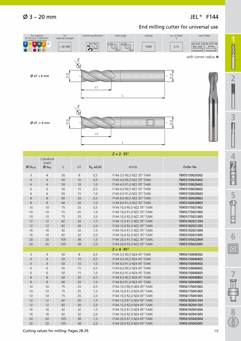
X 3 – 20 mm JeL® f144
Z = 2 35°
X Dh10 X dh6 L L1 Rn ±0,02
3 4 50 8 0,5 F144 3,0 R0,5 NZ2 35° TiAlN 789551500203024 4 50 10 0,5 F144 4,0 R0,5 NZ2 35° TiAlN 789551500204024 4 50 10 1,0 F144 4,0 R1,0 NZ2 35° TiAlN 789551500204036 6 50 15 0,5 F144 6,0 R0,5 NZ2 35° TiAlN 709551500206026 6 50 15 1,0 F144 6,0 R1,0 NZ2 35° TiAlN 709551500206038 8 60 20 0,5 F144 8,0 R0,5 NZ2 35° TiAlN 709551600208028 8 60 20 1,0 F144 8,0 R1,0 NZ2 35° TiAlN 7095516002080310 10 75 25 0,5 F144 10,0 R0,5 NZ2 35° TiAlN 7095517502100210 10 75 25 1,0 F144 10,0 R1,0 NZ2 35° TiAlN 7095517502100310 10 75 25 2,0 F144 10,0 R2,0 NZ2 35° TiAlN 7095517502100512 12 82 26 1,5 F144 12,0 R1,5 NZ2 35° TiAlN 7095518202120412 12 82 26 2,0 F144 12,0 R2,0 NZ2 35° TiAlN 7095518202120516 16 92 32 1,5 F144 16,0 R1,5 NZ2 35° TiAlN 7095519202160416 16 92 32 2,0 F144 16,0 R2,0 NZ2 35° TiAlN 7095519202160520 20 105 38 1,5 F144 20,0 R1,5 NZ2 35° TiAlN 7095510502200420 20 105 38 2,0 F144 20,0 R2,0 NZ2 35° TiAlN 70955105022005
Z = 4 45°3 4 50 8 0,5 F144 3,0 R0,5 NZ4 45° TiAlN 789561500403024 4 50 10 0,5 F144 4,0 R0,5 NZ4 45° TiAlN 789561500404024 4 50 10 1,0 F144 4,0 R1,0 NZ4 45° TiAlN 789561500404036 6 50 15 0,5 F144 6,0 R0,5 NZ4 45° TiAlN 709561500406026 6 50 15 1,0 F144 6,0 R1,0 NZ4 45° TiAlN 709561500406038 8 60 20 0,5 F144 8,0 R0,5 NZ4 45° TiAlN 709561600408028 8 60 20 1,0 F144 8,0 R1,0 NZ4 45° TiAlN 7095616004080310 10 75 25 0,5 F144 10,0 R0,5 NZ4 45° TiAlN 7095617504100210 10 75 25 1,0 F144 10,0 R1,0 NZ4 45° TiAlN 7095617504100310 10 75 25 2,0 F144 10,0 R2,0 NZ4 45° TiAlN 7095617504100512 12 82 26 1,5 F144 12,0 R1,5 NZ4 45° TiAlN 7095618204120412 12 82 26 2,0 F144 12,0 R2,0 NZ4 45° TiAlN 7095618204120516 16 92 32 1,5 F144 16,0 R1,5 NZ4 45° TiAlN 7095619204160416 16 92 32 2,0 F144 16,0 R2,0 NZ4 45° TiAlN 7095619204160520 20 105 38 1,5 F144 20,0 R1,5 NZ4 45° TiAlN 70956105042004
20 20 105 38 2,0 F144 20,0 R2,0 NZ4 45° TiAlN 70956105042005
L1
L
x D
x d
Rn
L1
L
x D
x d
Rn
X d1 < 6 mm
X d1 M 6 mm
P
§
M
$
K
§
N
$
S
$
H< 48 HRC
35°
Rn
45°
Rn TiAlN 2 / 4 Ød2 <6mm
K
Cutting values for milling: Pages 28-29.
end milling cutter for universal use
with corner radius
for material§ main area of application$ suitable in some cases
formaterial strength
machining direction helix angle coating no. of teethZ
tool holder
Cylindrical shank
Article Order no.

1
20
X 4 – 10 mmJeL® f142 XH
Z = 2
X Dh10 X dh6 X D1 L L1 L2 Rn ±0,02
4 6 3,7 50 4 10 0,5 F142 XH 4,0 R0,5 NZ2 30° AlTiN 78912250020402
6 6 5,6 50 6 15 0,5 F142 XH 6,0 R0,5 NZ2 30° AlTiN 78912250020602
8 8 7,6 60 8 20 0,5 F142 XH 8,0 R0,5 NZ2 30° AlTiN 78912260020802
8 8 7,6 60 8 20 1,0 F142 XH 8,0 R1,0 NZ2 30° AlTiN 78912260020803
8 8 7,6 60 8 20 2,0 F142 XH 8,0 R2,0 NZ2 30° AlTiN 78912260020805
10 10 9,6 75 10 25 0,5 F142 XH 10,0 R0,5 NZ2 30° AlTiN 78912275021002
10 10 9,6 75 10 25 1,0 F142 XH 10,0 R1,0 NZ2 30° AlTiN 78912275021003
10 10 9,6 75 10 25 2,0 F142 XH 10,0 R2,0 NZ2 30° AlTiN 78912275021005
Z = 4
4 6 3,7 75 4 10 0,5 F142 XH 4,0 R0,5 NZ4 30° AlTiN 78913275040402
6 6 5,6 75 6 15 0,5 F142 XH 6,0 R0,5 NZ4 30° AlTiN 78913275040602
6 6 5,6 75 6 15 1,0 F142 XH 6,0 R1,0 NZ4 30° AlTiN 78913275040603
8 8 7,6 100 8 20 0,5 F142 XH 8,0 R0,5 NZ4 30° AlTiN 78913200040802
8 8 7,6 100 8 20 1,0 F142 XH 8,0 R1,0 NZ4 30° AlTiN 78913200040803
10 10 9,6 100 10 25 1,0 F142 XH 10,0 R1,0 NZ4 30° AlTiN 78913200041003
10 10 9,6 100 10 25 2,0 F142 XH 10,0 R2,0 NZ4 30° AlTiN 78913200041005
L2
L
x D x d
Rn
L1
x D
1
P
$
M K N S H
§< 46-56
HRC 30°
RnAlTiN 2 / 4
KKK
end milling cutter for use on hardened steel
with corner radiuswith neck groovetwo front cutters to the centre
for material§ main area of application$ suitable in some cases
formaterial strength
machining direction helix angle coating no. of teethZ
tool holder
Cylindrical shank
Article Order no.

1
2
3
4
5
6
7
8
21
X 6 – 10 mm JeL® f170 XH
Z = 6
X Dh10 X dh6 L L1 Rn ±0,02
6 6 50 15 0,3 F170 XH 6,0 R0,3 NZ6 50° AlTiN 78914250060601
6 6 50 15 0,5 F170 XH 6,0 R0,5 NZ6 50° AlTiN 78914250060602
8 8 60 20 0,3 F170 XH 8,0 R0,3 NZ6 50° AlTiN 78914260060801
8 8 60 20 0,5 F170 XH 8,0 R0,5 NZ6 50° AlTiN 78914260060802
10 10 75 25 0,5 F170 XH 10,0 R0,5 NZ6 50° AlTiN 78914275061002
10 10 75 25 1,0 F170 XH 10,0 R1,0 NZ6 50° AlTiN 78914275061003
L1
L
x D x d
Rn
P
$
M K N S H
§< 50-65
HRC 50°
RnAlTiN 6
K
Cutting values for milling: Pages 28-29.
end milling cutter for finish machining on hardened steel
with corner radius
for material§ main area of application$ suitable in some cases
formaterial strength
machining direction helix angle coating no. of teethZ
tool holder
Cylindrical shank
Article Order no.

1
22
X 6 – 12 mmJeL® f742 XH
Z = 2
X Dh10 X dh6 X D1 L L1 L2 Rn ±0,02
6 6 5,4 100 8 30 1,5 F742 XH 6,0 R1,5 NZ2 30° AlTiN 78915200020604
8 8 7,2 100 10 30 2,0 F742 XH 8,0 R2,0 NZ2 30° AlTiN 78915200020805
10 10 9 100 12 35 2,5 F742 XH 10,0 R2,5 NZ2 30° AlTiN 78915200021006
12 12 11 105 14 40 3,0 F742 XH 12,0 R3,0 NZ2 30° AlTiN 78915205021207
L2
Rn
L
x D
x d
L1
x D
1
P
$
M K N S H
§< 46-56
HRC 30°
RnAlTiN 2
KKK
torus milling cutter
with neck groovefront cutting for plungingused especially in mould and die making for copy milling
for material§ main area of application$ suitable in some cases
formaterial strength
machining direction helix angle coating no. of teethZ
tool holder
Cylindrical shank
Article Order no.

1
2
3
4
5
6
7
8
23
X 6 – 12 mm JeL® fK02
Z = 3
X D X dh6 L V
6 6 57 60° FK02 6,0 60° NZ3 TiAlN 70920557030600
6 6 57 90° FK02 6,0 90° NZ3 TiAlN 70921557030600
8 8 63 60° FK02 8,0 60° NZ3 TiAlN 70920563030800
8 8 63 90° FK02 8,0 90° NZ3 TiAlN 70921563030800
Z = 4
10 10 72 60° FK02 10,0 60° NZ4 TiAlN 70920572041000
10 10 72 90° FK02 10,0 90° NZ4 TiAlN 70921572041000
12 12 82 60° FK02 12,0 60° NZ4 TiAlN 70920582041200
12 12 82 90° FK02 12,0 90° NZ4 TiAlN 70921582041200
L
x d
x D V
P
§
M
$
K
§
N
§
S
$
H< 58 HRC TiAlN 3 / 4
K
Cutting values for milling: Pages 28-29.
Chamfer milling cutter
for chamfering and deburring of workpiece edges
for material§ main area of application$ suitable in some cases
formaterial strength
machining direction coating no. of teethZ
tool holder
Cylindrical shank
Article Order no.

1
24
X 6 – 8 mmJeL® fZ02
Z = 4
X Dh6 X dh6 L Rn±0,02
6 8 70 1,0 FZ02 6,0 R1,0 NZ4 TiAlN 70922570040603
6 10 75 2,0 FZ02 6,0 R2,0 NZ4 TiAlN 70922575040605
6 12 75 3,0 FZ02 6,0 R3,0 NZ4 TiAlN 70922575040607
6 16 75 5,0 FZ02 6,0 R5,0 NZ4 TiAlN 70922575040609
7 8 70 0,5 FZ02 7,0 R0,5 NZ4 TiAlN 70922570040702
8 16 75 4,0 FZ02 8,0 R4,0 NZ4 TiAlN 70922575040808
8 20 80 6,0 FZ02 8,0 R6,0 NZ4 TiAlN 70922580040809
L
x d
x D
Rn
P
§
M
$
K
§
N
§
S
$
H< 58 HRC TiAlN 4
K
Radius milling cutter
for chamfering and deburring edges and contours
for material§ main area of application$ suitable in some cases
formaterial strength
machining direction coating no. of teethZ
tool holder
Cylindrical shank
Article Order no.

1
2
3
4
5
6
7
8
25
L1
L
x d
x D
X 3 – 20 mm JeL® f065 AL
Z = 2
X Dh6 X dh6 L L1
3 6 57 9 70933057020300
4 6 57 12 70933057020400
5 6 57 15 70933057020500
6 6 57 13 70933057020600
6 6 75 24 70933075020600
8 8 63 19 70933063020800
8 8 75 32 70933075020800
10 10 72 22 70933072021000
10 10 100 40 70933000021000
12 12 82 26 70933082021200
16 16 92 32 70933092021600
20 20 105 38 70933005022000
Z = 3
3 6 57 9 70934057030300
4 6 57 12 70934057030400
5 6 57 15 70934057030500
6 6 57 13 70934057030600
8 8 63 19 70934063030800
10 10 72 22 70934072031000
12 12 82 26 70934082031200
16 16 92 32 70934092031600
20 20 105 38 70934005032000
P M K N
§
S H
45°TiAlN 2 / 3
KK
Cutting values for milling: Pages 28-29.
end milling cutter for machining aluminium and non-ferrous metals
front-cuttingshort and long versions
for material§ main area of application$ suitable in some cases
machining direction helix angle coating no. of teethZ
tool holder
Cylindrical shank
Article Order no.
F065 AL 3,0 NZ2 45° short TiAlN
F065 AL 4,0 NZ2 45° short TiAlN
F065 AL 5,0 NZ2 45° short TiAlN
F065 AL 6,0 NZ2 45° short TiAlN
F065 AL 6,0 NZ2 45° long TiAlN
F065 AL 8,0 NZ2 45° short TiAlN
F065 AL 8,0 NZ2 45° long TiAlN
F065 AL 10,0 NZ2 45° short TiAlN
F065 AL 10,0 NZ2 45° long TiAlN
F065 AL 12,0 NZ2 45° short TiAlN
F065 AL 16,0 NZ2 45° short TiAlN
F065 AL 20,0 NZ2 45° short TiAlN
F065 AL 3,0 NZ3 45° short TiAlN
F065 AL 4,0 NZ3 45° short TiAlN
F065 AL 5,0 NZ3 45° short TiAlN
F065 AL 6,0 NZ3 45° short TiAlN
F065 AL 8,0 NZ3 45° short TiAlN
F065 AL 10,0 NZ3 45° short TiAlN
F065 AL 12,0 NZ3 45° short TiAlN
F065 AL 16,0 NZ3 45° short TiAlN
F065 AL 20,0 NZ3 45° short TiAlN

1
26
X 6 – 25 mmJeL® f066 Hf
Z = 2
X D X d × l L L1
6 6 × 36 57 12 F066 HF 6,0 NZ2 TiB2 78931057000600
8 8 × 36 63 16 F066 HF 8,0 NZ2 TiB2 78931063000800
10 10 × 40 72 20 F066 HF 10,0 NZ2 TiB2 78931072001000
12 12 × 45 83 24 F066 HF 12,0 NZ2 TiB2 78931083001200
16 16 × 48 90 35 F066 HF 16,0 NZ2 TiB2 78931090001600
20 20 × 50 104 40 F066 HF 20,0 NZ2 TiB2 78931004002000
25 25 × 56 120 45 F066 HF 25,0 NZ2 TiB2 78931020002500
L
x d
x D
lL1
ap = max. 2×D
ae = max. 0,5×D
ap = max. 1×D
P M K N
§
S H
45°TiB2 2
K
High-speed end milling cutter for aluminium machining
front-cutting
for material§ main area of application$ suitable in some cases
machining direction helix angle coating no. of teethZ
tool holder
Cylindrical shank
Article Order no.

1
2
3
4
5
6
7
8
27
X 4 – 8 mm JeL® fJ35 AL
Z = 1
X Dh6 X dh6 L L1
4 4 50 12 78935050010400
4 4 75 20 78935075010400
5 5 50 16 78935050010500
5 5 75 28 78935075010500
6 6 50 16 78935050010600
6 6 75 35 78935075010600
8 8 50 18 78935050010800
8 8 100 40 78935000010800
L
x dx D
L1
P M K N
§
S H
25°TiAlN 1
KK
Cutting values for milling: Pages 28-29.
end milling cutter with special geometry for aluminium and plastic machining
contour milling1 cutting edge
for material§ main area of application$ suitable in some cases
machining direction helix angle coating no. of teethZ
tool holder
Cylindrical shank
Article Order no.
FJ35 AL 4,0 NZ1 25° short TiAlN
FJ35 AL 4,0 NZ1 25° long TiAlN
FJ35 AL 5,0 NZ1 25° short TiAlN
FJ35 AL 5,0 NZ1 25° long TiAlN
FJ35 AL 6,0 NZ1 25° short TiAlN
FJ35 AL 6,0 NZ1 25° long TiAlN
FJ35 AL 8,0 NZ1 25° short TiAlN
FJ35 AL 8,0 NZ1 25° long TiAlN

x 3 – 20 mm x 6 – 20 mm x 6 – 20 mm x 3 – 20 mm x 6 – 16 mm x 6 – 20 mm x 3 – 20 mm x 3 – 16 mm x 6 – 16 mm x 3 – 20 mm x 4 – 10 mm x 6 – 10 mm x 6 – 12 mm x 6 – 12 mm x 6 – 8 mm x 3 – 20 mm x 6 – 25 mm x 4 – 8 mm2 – 4 2 – 4 4 4 – 8 6 – 16 4 2 – 4 2 2 – 4 2 – 4 2 – 4 6 2 3 – 4 4 2 – 3 2 1
DIN 6535 HB DIN 6535 HB DIN 6535 HB DIN 6535 HA DIN 6535 HA DIN 6535 HB DIN 6535 HB DIN 6535 HA DIN 6535 HA DIN 6535 HA/HB DIN 6535 HA DIN 6535 HA DIN 6535 HA DIN 6535 HB DIN 6535 HB DIN 6535 HB DIN 6535 HA DIN 6535 HATiAlN TiAlN TiAlN AlTiN AlTiN TiAlN TiAlN AlTiN AlTiN TiAlN AlTiN AlTiN AlTiN TiAlN TiAlN TiAlN TiB2 TiAlN
10 11 12 13 14 15 16 17 18 19 20 21 22 23 24 25 26 27
vc (m/min) Kf vc (m/min) Kf vc (m/min) Kf vc (m/min) Kf vc (m/min) Kf vc (m/min) Kf vc (m/min) Kf vc (m/min) Kf vc (m/min) Kf vc (m/min) Kf vc (m/min) Kf vc (m/min) Kf vc (m/min) Kf vc (m/min) vc (m/min) vc (m/min) Kf vc (m/min) Kf vc (m/min) Kf
P1.
1 m400 m120
1.2 m700 m200
1.3 m850 m250
1.4 m850 m250
1.5 >850
m1200>250m350
1.6 >1200 >350
H1.
7 m1400 m400
1.8 m2200 m600
M2.
1 m850 m250
2.2 m850 m250
2.3 m1000 m300
K3.
1 m500 m150
3.2 >500
m1000>150m300
3.3 400-
500200-250
3.4 m700 m200
3.5 >700
m1000>200m300
3.6 m700 m200
3.7 >700
<1000>200m300
S4.
1 m700 m200
4.2 m900 m270
4.3 >900
m1250>270m300
5.1 m500 m150
5.2 m900 <270
5.3 >900
m1200>270m350
N6.
1 m350 m100
6.2 m700 m200
6.3 m700 m200
6.4 m500 m470
7.1 m350 m100
7.2 m600 m180
7.3 m600 m180
7.4 m600 m180
7.5 m600 m180
8.1
8.2
8.3
1
28
165 2 165 2 180 2 165 2 170 p4 235 p4 225 p4 165 2 225 p4 165 165
135 2 135 2 160 2 150 2 160 p4 220 p4 210 p4 135 2 210 p4 135 135
125 2 125 2 140 2 140 2 150 p4 205 p4 200 p4 125 2 200 p4 125 125
125 2 125 2 140 2 140 2 150 p4 205 p4 200 p4 125 2 200 p4 125 125
100 1 100 1 120 1 120 1 130 p4 180 p4 175 p4 100 1 175 p4 100 100
90 1 90 1 100 1 100 1 95 p3 135 p3 125 p3 90 1 125 p3 90 90
80 4 80 4 145 p1 140 p1 80 p4 80 4 140 p1
60 4 60 4 125 p1 120 p1 60 p4 60 4 120 p1
75 1 75 1 110 1 95 p3 75 1 75 75
65 1 65 1 110 1 85 p2 65 1 65 65
70 1 70 1 110 1 75 p3 70 1 70 70
150 2 150 2 150 2 160 2 225 p4 305 p4 300 p4 150 2 300 p4 150 150
130 2 130 2 130 2 140 2 210 p4 280 p4 275 p4 130 2 275 p4 130 130
130 2 130 2 130 2 140 2 210 p4 280 p4 275 p4 130 2 275 p4 130 130
130 2 130 2 130 2 140 2 190 p4 260 p4 250 p4 130 2 250 p4 130 130
110 2 110 2 110 2 120 2 160 p4 220 p4 210 p4 110 2 210 p4 110 110
110 2 110 2 110 2 120 2 145 p4 200 p4 190 p4 110 2 190 p4 110 110
110 2 110 2 110 2 120 2 145 p4 200 p4 190 p4 110 2 190 p4 110 110
60 1 60 1 60 1 65 1 60 1 60 60
60 1 60 1 60 1 65 1 60 1 60 60
55 1 55 1 55 1 60 1 55 1 55 55
45 1 45 1 45 1 55 p2 45 1 45 45
35 1 35 1 35 1 55 p2 35 1 35 35
30 1 30 1 30 1 45 p2 30 1 30 30
175 3 175 3 190 3 145 p5 175 3 175 175 150 3 150 3
160 3 160 3 180 3 140 p5 160 3 160 160 140 3 140 3
175 3 175 3 190 3 145 p5 175 3 175 175 150 3 150 3
100 3 100 3 110 3 80 p5 100 3 100 100 80 3 80 3
280 3 280 3 310 3 520 p5 280 3 280 280 500 3 300 - 600 3 500 3
260 3 260 3 285 3 460 p5 260 3 260 260 420 3 300 - 600 3 420 3
260 3 260 3 285 3 460 p5 260 3 260 260 420 3 300 - 600 3 420 3
240 3 240 3 270 3 270 p5 240 3 240 240 270 3 200 - 500 3 270 3
200 3 200 3 220 3 220 p5 200 3 200 200 220 3 100 - 300 3 220 3
160 3 160 3 175 3 210 p5 160 3 160 160 150 3 150 3
175 3 175 3 190 3 225 p5 175 3 175 175 160 3 160 3
145 3 145 3 160 3 190 p5 145 3 145 145 120 3 120 3
Recommended application areasM
ater
ial G
roup
Stre
ngth
Rm
(N/m
m²)
Har
dnes
s H
B
type end milling cutter f044 Uni
end milling cutter f064 Uni
end milling cutter HPC
end milling cutter f072 XH
end milling cutter f041 XH
Roughing end mill f544
spherical cutterf344
spherical cutter f322 XH
spherical cutter f942 XH
end milling cutter f144
end milling cutter f142 XH
end milling cutter f170 XH
torus milling cutter f742 XH
Chamfer milling cutter fK02
Radius milling cutter fZ02
end milling cutter f065 AL
end milling cutter f066 Hf
end milling cutter fJ35 AL
DiameterNo. of teethShankCoatingPage
Material
magnetic soft iron
structural, case hardened steel
carbon steel
alloy steel
alloy/heat treated steel
alloy/heat treated steel
hardened steel to 56 HRC
hardened steel to 65 HRC
stainless steel, sulphuretted
austentic
ferritic, ferritic & austentic, martensitic
grey cast iron
grey cast iron, heat treated
vermicular cast iron
spheroidal graphite cast iron
spheroidal graphite cast iron, heat treated
malleable iron
malleable iron, heat treated
pure titanium
titanium alloys
titanium alloys
pure nickel
nickel alloys, heat resistant
nickel alloys, high heat resistant
non-alloy copper
short chip, brass, bronze, red brass
long chip brass
Cu-Al-Fe alloy (Ampco)
Al, Mg non-alloy
Al wrought alloy, breaking strain (A5) <14 %
Al wrought alloy, breaking strain (A5) ≥14 %
Al cast alloy, Si <10 %
Al cast alloy, Si ≥10 %
thermoplastics
thermosetting plastics
fibre reinforced plastics
JeL® solid carbide milling cutter
vc = Cutting speed; Kf = Correction factor for feed fz (page 31)

x 3 – 20 mm x 6 – 20 mm x 6 – 20 mm x 3 – 20 mm x 6 – 16 mm x 6 – 20 mm x 3 – 20 mm x 3 – 16 mm x 6 – 16 mm x 3 – 20 mm x 4 – 10 mm x 6 – 10 mm x 6 – 12 mm x 6 – 12 mm x 6 – 8 mm x 3 – 20 mm x 6 – 25 mm x 4 – 8 mm2 – 4 2 – 4 4 4 – 8 6 – 16 4 2 – 4 2 2 – 4 2 – 4 2 – 4 6 2 3 – 4 4 2 – 3 2 1
DIN 6535 HB DIN 6535 HB DIN 6535 HB DIN 6535 HA DIN 6535 HA DIN 6535 HB DIN 6535 HB DIN 6535 HA DIN 6535 HA DIN 6535 HA/HB DIN 6535 HA DIN 6535 HA DIN 6535 HA DIN 6535 HB DIN 6535 HB DIN 6535 HB DIN 6535 HA DIN 6535 HATiAlN TiAlN TiAlN AlTiN AlTiN TiAlN TiAlN AlTiN AlTiN TiAlN AlTiN AlTiN AlTiN TiAlN TiAlN TiAlN TiB2 TiAlN
10 11 12 13 14 15 16 17 18 19 20 21 22 23 24 25 26 27
vc (m/min) Kf vc (m/min) Kf vc (m/min) Kf vc (m/min) Kf vc (m/min) Kf vc (m/min) Kf vc (m/min) Kf vc (m/min) Kf vc (m/min) Kf vc (m/min) Kf vc (m/min) Kf vc (m/min) Kf vc (m/min) Kf vc (m/min) vc (m/min) vc (m/min) Kf vc (m/min) Kf vc (m/min) Kf
P1.
1 m400 m120
1.2 m700 m200
1.3 m850 m250
1.4 m850 m250
1.5 >850
m1200>250m350
1.6 >1200 >350
H1.
7 m1400 m400
1.8 m2200 m600
M2.
1 m850 m250
2.2 m850 m250
2.3 m1000 m300
K3.
1 m500 m150
3.2 >500
m1000>150m300
3.3 400-
500200-250
3.4 m700 m200
3.5 >700
m1000>200m300
3.6 m700 m200
3.7 >700
<1000>200m300
S4.
1 m700 m200
4.2 m900 m270
4.3 >900
m1250>270m300
5.1 m500 m150
5.2 m900 <270
5.3 >900
m1200>270m350
N6.
1 m350 m100
6.2 m700 m200
6.3 m700 m200
6.4 m500 m470
7.1 m350 m100
7.2 m600 m180
7.3 m600 m180
7.4 m600 m180
7.5 m600 m180
8.1
8.2
8.3
1
2
3
4
5
6
7
8
29
165 2 165 2 180 2 165 2 170 p4 235 p4 225 p4 165 2 225 p4 165 165
135 2 135 2 160 2 150 2 160 p4 220 p4 210 p4 135 2 210 p4 135 135
125 2 125 2 140 2 140 2 150 p4 205 p4 200 p4 125 2 200 p4 125 125
125 2 125 2 140 2 140 2 150 p4 205 p4 200 p4 125 2 200 p4 125 125
100 1 100 1 120 1 120 1 130 p4 180 p4 175 p4 100 1 175 p4 100 100
90 1 90 1 100 1 100 1 95 p3 135 p3 125 p3 90 1 125 p3 90 90
80 4 80 4 145 p1 140 p1 80 p4 80 4 140 p1
60 4 60 4 125 p1 120 p1 60 p4 60 4 120 p1
75 1 75 1 110 1 95 p3 75 1 75 75
65 1 65 1 110 1 85 p2 65 1 65 65
70 1 70 1 110 1 75 p3 70 1 70 70
150 2 150 2 150 2 160 2 225 p4 305 p4 300 p4 150 2 300 p4 150 150
130 2 130 2 130 2 140 2 210 p4 280 p4 275 p4 130 2 275 p4 130 130
130 2 130 2 130 2 140 2 210 p4 280 p4 275 p4 130 2 275 p4 130 130
130 2 130 2 130 2 140 2 190 p4 260 p4 250 p4 130 2 250 p4 130 130
110 2 110 2 110 2 120 2 160 p4 220 p4 210 p4 110 2 210 p4 110 110
110 2 110 2 110 2 120 2 145 p4 200 p4 190 p4 110 2 190 p4 110 110
110 2 110 2 110 2 120 2 145 p4 200 p4 190 p4 110 2 190 p4 110 110
60 1 60 1 60 1 65 1 60 1 60 60
60 1 60 1 60 1 65 1 60 1 60 60
55 1 55 1 55 1 60 1 55 1 55 55
45 1 45 1 45 1 55 p2 45 1 45 45
35 1 35 1 35 1 55 p2 35 1 35 35
30 1 30 1 30 1 45 p2 30 1 30 30
175 3 175 3 190 3 145 p5 175 3 175 175 150 3 150 3
160 3 160 3 180 3 140 p5 160 3 160 160 140 3 140 3
175 3 175 3 190 3 145 p5 175 3 175 175 150 3 150 3
100 3 100 3 110 3 80 p5 100 3 100 100 80 3 80 3
280 3 280 3 310 3 520 p5 280 3 280 280 500 3 300 - 600 3 500 3
260 3 260 3 285 3 460 p5 260 3 260 260 420 3 300 - 600 3 420 3
260 3 260 3 285 3 460 p5 260 3 260 260 420 3 300 - 600 3 420 3
240 3 240 3 270 3 270 p5 240 3 240 240 270 3 200 - 500 3 270 3
200 3 200 3 220 3 220 p5 200 3 200 200 220 3 100 - 300 3 220 3
160 3 160 3 175 3 210 p5 160 3 160 160 150 3 150 3
175 3 175 3 190 3 225 p5 175 3 175 175 160 3 160 3
145 3 145 3 160 3 190 p5 145 3 145 145 120 3 120 3
Recommended application areas
Mat
eria
l Gro
up
Stre
ngth
Rm
(N/m
m²)
Har
dnes
s H
B
type end milling cutter f044 Uni
end milling cutter f064 Uni
end milling cutter HPC
end milling cutter f072 XH
end milling cutter f041 XH
Roughing end mill f544
spherical cutterf344
spherical cutter f322 XH
spherical cutter f942 XH
end milling cutter f144
end milling cutter f142 XH
end milling cutter f170 XH
torus milling cutter f742 XH
Chamfer milling cutter fK02
Radius milling cutter fZ02
end milling cutter f065 AL
end milling cutter f066 Hf
end milling cutter fJ35 AL
DiameterNo. of teethShankCoatingPage
Material
JeL® solid carbide milling cutter
important: see chapter 8 for more application details and safety notes!

1
30
ae = x D
a p =
0,5
× D
ae = 0,5 × D
a p =
0,5
× D
ae = 0,05 × D
a p =
1,5
× D
x D
a p =
0,0
5 ×
D
ae = 0,05 × D
max
. 80°
technical notes
slot millingvc slot = 0,7 × vc
Rough millingvc rough = vc
finish millingvc finish = 1,5 × vc
JeL® solid carbide milling cutter

0,14
0,12
0,10
0,08
0,06
0,04
0,02
0 5 10 15 20 25
0,16
0,14
0,12
0,10
0,08
0,06
0,04
0,02
0 5 10 15 20 25
0,26
0,24
0,22
0,20
0,18
0,16
0,14
0,12
0,10
0,08
0,06
0,04
0,02
0 5 10 15 20 25
0,06
0,05
0,04
0,03
0,02
0,01
0 5 10 15 20 25
0,40
0,35
0,30
0,25
0,20
0,15
0,10
0,05
0 5 10 15 20 25
1
2
3
4
5
6
7
8
31
x D (mm)
Kf 1
ae = 0,2 m
m
ae = 0,5 m
m × D
ae = D
x D (mm)
Kf 2
ae = 0,2 m
m
ae = 0,5 mm × D
ae = D
x D (mm)
Kf 3
ae =
0,2
mm
ae = 0,
5 mm
× D
ae = D
x D (mm)
ae = 0,01 mm × D
ae = 0,02 mm × D
ae = 0,05 mm × D
x D (mm)
Kf p1-p5
p1
p2
p3
p4
p5
Correction factor Kf
for feed fz
Feed
fz
(mm
/too
th)
Feed
fz
(mm
/too
th)
Feed
fz
(mm
/too
th)
Feed
fz
(mm
/too
th)
Kf 4 – hardened steelap max. = 0,2 mm
Feed
fz
(mm
/too
th)
important: see chapter 8 for more application details and safety notes!
JeL® solid carbide milling cutter

1
2
32
KOMet® Diamond coated milling tools

1
2
3
4
5
6
7
8
33
35
3636
3636
3737
3737
3838
In an era of increasing awareness of the issues surrounding energy, energy conservation and energy efficiency, the lightweight construction segment is becoming more and more important. At a rapid pace, composite materials are carving out ever larger market shares.
Outstanding material properties, however, also present challenges for the manufacturers of precision tools. The extremely high strength and complex make-up of these materials are placing new demands on the tools that work them: the high degree of abrasiveness means that conventional tools in drilling and milling setups last only a few metres.
In light of this requirement, the KOMET GROUP has developed a brand new class of tools distinguished by their innovative geometry, suitability for new machining strategies involv-ing very high cutting parameters and also by the use of intelligent cutting materials. These new solutions range from single-edge to multi-tooth milling cutters and from drills with a new chamfer geometry to indexable tools having a special insert arrangement.
Cutting materials have also followed the trend: KOMET RHOBEST® diamond coatings and PCD solutions are demonstrating that they are fully equipped for the task.
Versions:
- NCD Composite milling cutter, HSC - NCD Composite multi-tooth milling cutter
- PCD Slot milling cutter and PCD Compression milling cutter see chapter 3
- NCD and PCD High-performance drill see catalogue "TOOLS PLUS IDEAS"
KOMet® Page
tool selection
nCD Composite milling cutter, HsC
Type FZ, flat head Type FZ, burr style
Type FZ, ball noseType GZ, ball nose
Type FZ, 2 front cuttersType GZ, 2 front cutters
Type FZ, 2 front cutters, 135° drill centreType GZ, 2 front cutters, 135° drill centre
nCD Composite multi-tooth milling cutter
straight teethhelical teeth, pull cut
PCD slot milling cutterPCD Compression milling cutter
Chapter 3
nCD High-performance drill DrillmaxPCD High-performance drill Drillmax
CatalogueTOOLS PLUS
IDEAS

1
2
34
KOMet® nCD
fiBROUs COMPOsite MAteRiALs
Fibrous composites are inhomogeneous materials that are essentially an assembly of three components – fibres and matrices or binders.
Typical fibres include carbon fibre (CFRP), glass fibre (GFRP) or aramid fibre (AFRP). With respect to their tensile strength, they are categorised into HT (high tenacity), UT (ultra high tenacity) and IM (intermediate modulus). Depending on the properties desired, the fibres differ in length, thickness and relative orientation (unidirectional, bidirectional, multidirectional).
As matrices, there are currently more than 100 different resins/polymers available on the market, which is just a hint at how varied these materials are. “Cold” cutting is generally recommended for duroplastics (90%) and thermoplastics (PEEK, PEI, PPS, etc.), while elastomers (PUR) should be cut at “high speed”.
Applications: Aerospace, automotive, medical industry, sports industry, wind farms, transport, building/architecture
HYBRiDs
Hybrids are material combinations of at least three layers of metals, poly-mers and fibrous composites.
Application: Aircraft construction
HOneYCOMBs
These materials are usually three-layer composite constructions with a honeycomb-shaped core made, for example, of aluminium, polycarbonate or polypropylene and are therefore characterised by their extremely light-weight and highly stiff properties.
Applications: Satellite engineering, packaging industry, exhibition stand, model and aircraft construction
MetAL MAtRiX COMPOsite MAteRiAL
Metal matrix composites (MMC) have at least two constituent materials, usually a ceramic or organic component bonded in a metal matrix.
Applications: Engine building, cylinder liners, connecting rods
The non-homogeneous nature of these new lightweight materials imposes exacting and individual requirements on the machining process. Not only does the KOMET GROUP offer a standard product range, it is an expert partner for its customers – with absolute focus on problem-solving.
Thanks to full process control in-house – from carbide/cutting material selection, consolidated expertise and many years of experience in grind-ing through to final coating – the KOMET GROUP is your single source of smart and viable machining solutions.
The standard product range presented here enables you to order the right tool for your applications and feasibility tests with zero fuss.
All other specifications including inch measurements can be created for you on request and tailored to your individual requirements.
We would be delighted to collaborate with you to develop new machining strategies. We offer a modern machining environment to conduct tests in-house or we can visit you to coordinate further. Interested? Simply contact our experts in lightweight construction at www.kometgroup.com
Classification of composite materials and typical applications

1
2
3
4
5
6
7
8
35
§ § 36
§ § 36
§ § 36
§ § 36
§ § 37
§ § 37
§ § 37
§ § 37
§ § § § 38
§ § § § 38
KOMet® nCD
tool selection
§ main area of application, $ suitable in some cases. Other materials and combinations on request.
Material tool Page
CfRP GfRPCfRP/Al stacks
Honey-combs
nCD Composite milling cutter, HsC type FZ, flat head78980..
nCD Composite milling cutter, HsC type FZ, burr style78981..
nCD Composite milling cutter, HsC type FZ, ball nose78982..
nCD Composite milling cutter, HsC type GZ, ball nose78983..
nCD Composite milling cutter, HsC type FZ, 2 front cutters78984..
nCD Composite milling cutter, HsC type GZ, 2 front cutters78985..
nCD Composite milling cutter, HsC type FZ, 2 front cutters, 135° drill centre78986..
nCD Composite milling cutter, HsC type GZ, 2 front cutters, 135° drill centre78987..
nCD Composite multi-tooth milling cutterstraight teeth78988..
nCD Composite multi-tooth milling cutterhelical teeth, pull cut78989..
nCD high-performance drill Drillmax 90With a point angle of 90°, the Drillmax 90 NCD high-performance drill is excellently suited for drilling composite materials.

1
2
36
KKKKK
N
L
x d
x D
l
N
L
x d
x D
l
N
L
x d
x D
l
N
L
x d
x D
l
KKKKK
KKKKK
78980..
X Dh10 X dh6 × l L n
4 4 × 20 40 15 78980040000400
4 4 × 55 75 15 78980075000400
6 6 × 25 50 18 78980050000600
6 6 × 48 75 18 78980075000600
8 8 × 30 63 25 78980063000800
8 8 × 42 75 25 78980075000800
10 10 × 37 72 30 78980072001000
78981..
X Dh10 X dh6 × l L n
4 4 × 20 40 15 78981040000400
4 4 × 55 75 15 78981075000400
6 6 × 25 50 18 78981050000600
6 6 × 48 75 18 78981075000600
8 8 × 30 63 25 78981063000800
8 8 × 42 75 25 78981075000800
10 10 × 37 72 30 78981072001000
12 12 × 32 83 32 78981083001200
78982..
X Dh10 X dh6 × l L n
4 4 × 28 50 16 78982050000400
6 6 × 34 60 19 78982060000600
8 8 × 28 63 25 78982063000800
10 10 × 40 72 25 78982072001000
78983..
X Dh10 X dh6 × l L n
4 4 × 28 50 16 78983050000400
6 6 × 34 60 19 78983063000600
8 8 × 28 63 25 78983060000800
10 10 × 40 72 25 78983072001000
KOMet® nCD
milling and trimmingtype FZ (fine-tooth)flat headshank to DIN 6535 HAcutting material: diamond
nCD Composite milling cutter, HsC
milling and trimmingtype FZ (fine-tooth)burr styleshank to DIN 6535 HAcutting material: diamond
nCD Composite milling cutter, HsC
slot milling and plunge millingtype FZ (fine-tooth), type GZ (coarse-tooth)ball noseshank to DIN 6535 HAcutting material: diamond
nCD Composite milling cutter, HsC
type fZCylindrical
shankOrder no.
type fZCylindrical
shankOrder no.
type fZCylindrical
shankOrder no.
type GZCylindrical
shankOrder no.

1
2
3
4
5
6
7
8
37
N
L
x d
x D
l
N
L
x d
x D
l
KKKKK
N
L
x d
x D
l
N
L
x d
x D
l
KKKKK
78984..
X Dh10 X dh6 × l L n
4 4 × 28 50 16 78984050000400
4 4 × 52 75 15 78984075000400
6 6 × 34 60 19 78984060000600
6 6 × 38 75 30 78984075000600
8 8 × 28 63 25 78984063000800
8 8 × 30 75 35 78984075000800
10 10 × 40 72 25 78984072001000
78985..
X Dh10 X dh6 × l L n
4 4 × 28 50 16 78985050000400
4 4 × 52 75 15 78985075000400
6 6 × 34 60 19 78985060000600
6 6 × 38 75 30 78985075000600
8 8 × 28 63 25 78985063000800
8 8 × 30 75 35 78985075000800
10 10 × 40 72 25 78985072001000
78986..
X Dh10 X dh6 × l L n
4 4 × 28 50 16 78986050000400
4 4 × 52 75 15 78986075000400
6 6 × 34 60 19 78986060000600
6 6 × 48 75 18 78986075000600
8 8 × 28 60 25 78986060000800
8 8 × 30 75 25 78986075000800
10 10 × 40 72 25 78986072001000
78987..
X Dh10 X dh6 × l L n
4 4 × 28 50 16 78987050000400
4 4 × 52 75 15 78987075000400
6 6 × 34 60 19 78987060000600
6 6 × 48 75 18 78987075000600
8 8 × 28 60 25 78987060000800
8 8 × 30 75 25 78987075000800
10 10 × 40 72 25 78987072001000
X 4 mm X 6 mm X 8 mm X 10 mm X 12 mmvc f vc f vc f vc f vc f
100 - 200 0,06 - 0,10 100 - 300 0,08 - 0,12 100 - 300 0,10 - 0,15 100 - 300 0,10 - 0,20 100 - 300 0,10 - 0,25
120 - 200 0,06 - 0,12 100 - 300 0,08 - 0,15 100 - 300 0,10 - 0,20 100 - 300 0,10 - 0,25 100 - 300 0,10 - 0,30
KOMet® nCD
plunge milling and trimmingtype FZ (fine-tooth), type GZ (coarse-tooth)2 front cuttersshank to DIN 6535 HAcutting material: diamond
nCD Composite milling cutter, HsC
trimming, slot milling, plunge milling and shoulder millingtype FZ (fine-tooth), type GZ (coarse-tooth)2 front cutters, 135° drill centreshank to DIN 6535 HAcutting material: diamond
nCD Composite milling cutter, HsC
type fZCylindrical
shankOrder no.
type GZCylindrical
shankOrder no.
type fZCylindrical
shankOrder no.
type GZCylindrical
shankOrder no.
Recommended application areas
nCD Composite milling cutter, HsC (78980.. · 78981.. · 78982.. · 78983.. · 78984.. · 78985.. · 78986.. · 78987..)
Machining: trimming, circular cutting, grooving, ramping, plunging, pocket and slot milling
Cutting speed vc (m/min) Feed f (mm/rev)
CFRP
GFRP
important: see chapter 8 for more application details and safety notes!

1
2
38
N
L
x d
x D
l
N
L
x d
x D
l
KKKKK
KKKKK
78988..
X Dh10 X dh6 × l L n Z
4 6 × 30 60 16 6 78988060000400
6 6 × 28 60 20 8 78988060000600
6 6 × 30 75 28 8 78988075000600
8 8 × 28 63 22 8 78988063000800
8 8 × 32 75 32 8 78988075000800
10 10 × 30 72 32 8 78988072001000
78989..
X Dh10 X dh6 × l L n Z
4 6 × 30 60 16 6 78989060000400
6 6 × 28 60 20 8 78989060000600
6 6 × 30 75 28 8 78989075000600
8 8 × 28 63 22 8 78989063000800
8 8 × 32 75 32 8 78989075000800
10 10 × 30 72 32 8 78989072001000
X 4 mm X 6 mm X 8 mm X 10 mmvc fz vc fz vc fz vc fz
100 - 200 0,02 - 0,04 100 - 300 0,02 - 0,06 100 - 300 0,02 - 0,08 100 - 300 0,02 - 0,10
100 - 200 0,02 - 0,06 100 - 300 0,02 - 0,08 100 - 300 0,02 - 0,10 100 - 300 0,02 - 0,12
100 - 200 0,02 - 0,04 100 - 300 0,02 - 0,06 100 - 300 0,02 - 0,08 100 - 300 0,02 - 0,10
100 - 200 0,02 - 0,04 100 - 300 0,02 - 0,06 100 - 300 0,02 - 0,08 100 - 300 0,02 - 0,10
KOMet® nCD
nCD Composite multi-tooth milling cutter
helical teeth, pull cutburr style, every second tooth exposedfine chip breakershank to DIN 6535 HAcutting material: diamond
nCD Composite multi-tooth milling cutter
Cylindricalshank
No. of teeth
Order no.
Cylindricalshank
No. of teeth
Order no.
straight teethburr style, every second tooth exposedfine chip breakershank to DIN 6535 HAcutting material: diamond
nCD Composite multi-tooth milling cutter (78988.. · 78989..)
Machining: trimming, circular cutting, axial grooving, pocket and slot milling
Cutting speed vc (m/min)Feed fz (mm/tooth)
CFRP
GFRP
CFRP/Al stacks
Honeycombs
Recommended application areas
important: see chapter 8 for more application details and safety notes!

1
2
3
4
5
6
7
8
39
43
3
3
5
212
3
3
6
5
KOMet RHOBest®
Already in 1994, RHOBEST has been developing and continually adapting the nanocrystalline diamond coating to the tools used in specific machining processes.
In 2011, this nanotechnology became part of the KOMET GROUP. With KOMET RHOBEST® diamond coating technology, the sur-faces and properties of tools for machining composite materials can be individually tailored to meet the requirements of the particular application.
KOMET RHOBEST® diamond coating technology has made it possible to manufacture ultrananocrystalline, highly pure and extremely hard diamond coatings that join with the tool surface to form a compact and stable unit.
micro ultra nano
standard technology
KOMet RHOBest® technology
Thanks to this nanostructure, the geometry and surface of the optimised tool are retained, thin coatings are compact, wear-resistant and high-performing. The sharpness of the tool – an important prerequisite for the machining of fibrous composite materials – is preserved.
With KOMET RHOBEST® diamond-coated tools, we meet the requirements for machining new lightweight materials – absence of burr and fibre, a smooth, flat cutting edge, suitability for painting and bonding, short machining times and long tool life.
Machining CfRP material
nano technology in lightweight construction
1 Solid drilling with PCD High-performance drill Drillmax 902 Solid drilling with NCD High-performance drill Drillmax 903 Slot milling with PCD Slot milling cutter straight fluted (38304..)4 Interpolation milling with NCD Composite multi-tooth milling cutter, helical teeth, pull cut (78989..)5 Circular and slot milling with NCD Composite milling cutter, HSC type FZ, straight teeth (78981..)6 Slot milling with NCD Composite milling cutter, HSC type FZ, 2 front cutters, 135° drill centre (78986..)

1
2
3
40
KOMet® PCD slot milling cutter and PCD face milling cutter
PCD screw-in cutters for grooving and face milling
Milling shoulders and grooves, making circular drilled holes on a helix path, and face and peripheral milling are typical operations that occur frequently when machining components.
Among the selling points of the new JEL® PCD milling cutters are that they are highly flexible and easy to handle.
The modular system allows you to choose between brazed PCD face milling cutters and PCD slot milling cutters. It also contains a vibration-dampened tool shank available in various lengths.
The milling heads are available in diameters of 10 to 32 mm. The heads can be changed quickly and easily on the machine itself.
Benefits for you:
Tool versatility and reduction of costs thanks to modular head system
Great flexibility since a variety of lengths can be adapted
Good availability: PCD slot milling cutter and PCD face milling cutter: available ex stock
Machining example:
Tool: JEL® PCD slot milling cutter x20 NZ2, internal coolingPart: Inverter housing, AlSi9
Machining: Pocket milling, root face 12 mm thick, drilling, roughing, finishing
Current situation: Solid carbide tool, A = 230 mm
Problem: Heavy vibrations
Solution: JEL® PCD slot milling cutter shrinked into heavy metal extension
Cutting data:vc = 754 m/min = 12,000 rpm (Smax.)fz = 0.2 mm/tooth = 4,800 mm/min
Application:- For roughing and finishing in aluminium- Face milling, slot milling, peripheral milling and circular
milling, as well as machining shoulders and grooves- As a "problem solver" for long overhangs

1
2
3
4
5
6
7
8
41
42 – 43
4445
4647
48 – 49
50
51
52 – 53
PCD face milling cutterThe JEL® PCD face milling cutter is noteworthy for its outstanding cost efficiency. High feeds, cutting depth and longest tool lifes can be achieved thanks to the high number of teeth and solid design.
Machining example: Part: housingMachine: Chiron Mill 2000Machining: Face milling of the sealing surface and mounting domes, upper side and underside Material: GAlSi9Cutting depth: 4 mmTool: 37150026004000, PCD face milling cutter x40, NZ10 HSK-A63Cutting data:vc =1,507 m/min = 12,000 rpm (Smax.)fz = 0.05 mm/tooth = 6,000 mm/minSurface finish: Rz 1.51-2.50
Applications:Mainly suited to roughing and finishing cast or solid aluminium.
Sectors: Automotive, aerospace, aluminium foundries, pneumatics and hydraulics
Benefits for you:
Cutting depths of up to 8 mm thanks to firmly soldered cutting edges
in a solid basic body
short cycle times thanks to maximum number of cutting
edges and highest cutting speeds
no adjustment necessary thanks to Monoblock design
Attainable surface quality Rz < 10 µm (type 150) thanks to fine balancing and extremely
tight manufacturing tolerances
Available in two variants type 140: for Rz > 10 µm - with eroded
cutting edge design type 150: for Rz < 10 µm - with special
cutting edge design
internal cooling supply fed to the cutting edge via a coolant
screw
Available at short notice PCD face milling cutter available ex
stock
PCD Milling cutter Page
PCD tools
for defined surfaces
PCD slot milling cutter
x 6 – 20 mmx 10 – 25 mm (screw-on)
PCD face milling cutter
x 10 – 32 mm (screw-on)x 40 – 160 mm
Recommended application areas
PCD slot milling cutter
for machining composite materialsx 6 – 10 mm
PCD Compression milling cutter
for machining composite materialsx 6 – 16 mm
PCD finishing, facing and corner milling cutter
HSC operationsx 63 – 100 mm (DIN 8030)
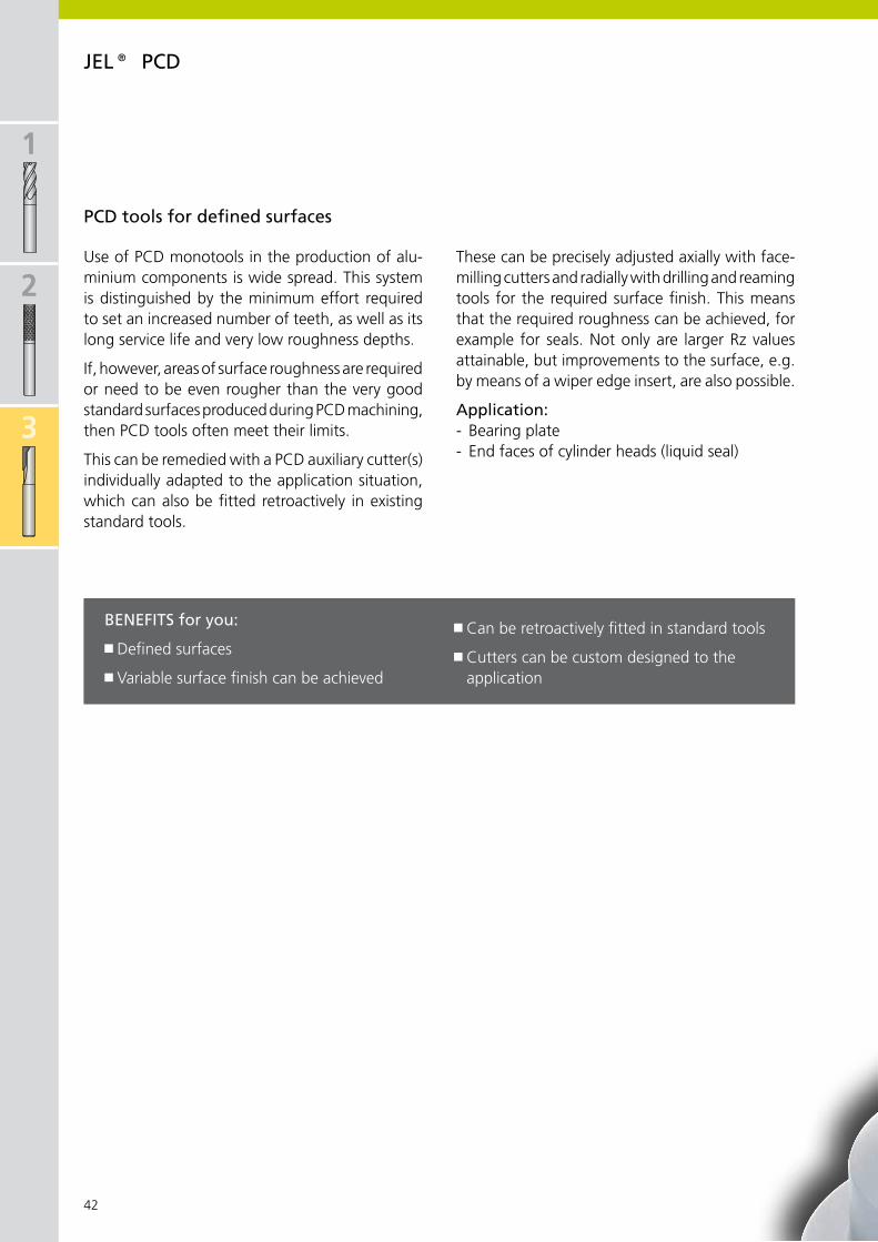
1
2
3
42
Use of PCD monotools in the production of alu-minium components is wide spread. This system is distinguished by the minimum effort required to set an increased number of teeth, as well as its long service life and very low roughness depths.
If, however, areas of surface roughness are required or need to be even rougher than the very good standard surfaces produced during PCD machining, then PCD tools often meet their limits.
This can be remedied with a PCD auxiliary cutter(s) individually adapted to the application situation, which can also be fitted retroactively in existing standard tools.
These can be precisely adjusted axially with face-milling cutters and radially with drilling and reaming tools for the required surface finish. This means that the required roughness can be achieved, for example for seals. Not only are larger Rz values attainable, but improvements to the surface, e.g. by means of a wiper edge insert, are also possible.
Application:- Bearing plate- End faces of cylinder heads (liquid seal)
Benefits for you:
Defined surfaces
Variable surface finish can be achieved
Can be retroactively fitted in standard tools
Cutters can be custom designed to the application
PCD tools for defined surfaces
JeL® PCD

1
2
3
4
5
6
7
8
43
surfaces can be defined by adjustable PCD cutters
JeL® PCD

1
2
3
44
X 6 – 20 mm
KKKKKKKK
1×D
X D X d × l L L1 Z
6 6 × 36 57 6 2 38390000000600
8 8 × 36 63 8 2 38390000000800
10 10 × 40 72 10 2 38390000001000
12 12 × 45 83 12 2 38390000001200
16 16 × 48 90 16 3 38391000001600
20 20 × 50 104 20 3 38391000002000
2×D
6 6 × 36 57 12 2 38392057000600
8 8 × 36 63 16 2 38392063000800
10 10 × 40 72 20 2 38392072001000
12 12 × 45 83 24 2 38392083001200
16 16 × 48 90 32 3 38393090001600
20 20 × 50 104 40 3 38393004002000
x D
x d
L
lL1
PCD slot milling cutter
excellent tool characteristics for top quality and long tool lifesuitable for: Internal circular interpolation milling, external circular interpolation milling, centred boring1 cutting edge over centre straight flutedinternal coolant supplyshank-x DIN 6535 form HAsolid carbide basic bodycutting material PCD
No. of teethCylindrical shankOrder no.
JeL® PCD

1
2
3
4
5
6
7
8
45
L1
L
x D M
x D
1
X 10 – 25 mm
KK
X D M X D1 L L1 Z
10 M5 7 Nm 9,6 28 10 2 0,018 37340099001000
12 M5 7 Nm 9,6 28 12 2 0,018 37340099001200
16 M8 15 Nm 13,8 32 16 3 0,036 37340099001600
20 M10 30 Nm 18,0 45 20 3 0,095 37340099002000
25 M12 50 Nm 21,0 45 20 3 0,165 37340099002500
PCD slot milling cutter
JeL® PCD
Adapter see chapter 7
Cutting values for milling: Page 48.
No. of teethTightening torque Order no.
screw-oninternal coolant supply, lateral discharge

1
2
3
46
X 10 – 32 mm
X D M X D1 L L1 Z
10 M5 7 Nm 9,6 22 5 2 0,012 37341099001000
12 M5 7 Nm 9,6 28 5 2 0,018 37341099001200
16 M8 15 Nm 13,8 28 10 3 0,040 37341099001600
20 M10 30 Nm 18,0 30 10 4 0,070 37341099002000
25 M12 50 Nm 21,0 35 10 5 0,140 37341099002500
32 M16 100 Nm 29,0 35 10 6 0,250 37341099003200
KK
L1
L
x D M
x D
1
PCD face milling cutter
No. of teethTightening torque Order no.
JeL® PCD
screw-oninternal coolant supply, lateral discharge
Adapter see chapter 7

1
2
3
4
5
6
7
8
47
typ 140 · Rz > 10 µm typ 150 · Rz < 10 µm
HsKX D X d L L1 L2 Z
±0,02
40 63 100 21 10 10 1,4 37140026004000 37150026004000
50 63 100 21 10 12 1,7 37140026005000 37150026005000
63 63 100 20 10 14 2,0 37140026006300 37150026006300
80 63 100 20 10 16 2,5 37140026008000 37150026008000
100 63 100 20 10 18 3,2 37140026010000 37150026010000
125 63 100 23 10 22 4,3 37140026012500 37150026012500
160 63 100 22 10 22 6,2 37140026016000 37150026016000
L1
L
L2
x D
X 40 – 160 mm
HSK
x d
Z
KKK
supply includes: PCD face milling cutter with coolant screw and coolant supply kit.
PCD face milling cutter
Other connections and cutting edge shapes available on request.
No. of teeth
Order no. Order no.
JeL® PCD
internal coolant supplychamfer type 140: eroded cutting edge
chamfer type 150: specially design cutting edge
Cutting values for milling: Page 49.

x 6 x 8 x 10 x 12 x 16 | 20 | 25
vc fz vc fz vc fz vc fz vc fzm/min m/min m/min m/min m/min
P1.
1 m400 m120
1.2 m700 m200
1.3 m850 m250
1.4 m850 m250
1.5 >850
m1200>250m350
1.6 >1200 >350
H1.
7 m1400 m400
1.8 m2200 m600
M2.
1 m850 m250
2.2 m850 m250
2.3 m1000 m300
K3.
1 m500 m150
3.2 >500
m1000>150m300
3.3 400-
500200-250
3.4 m700 m200
3.5 >700
m1000>200m300
3.6 m700 m200
3.7 >700
<1000>200m300
S4.
1 m700 m200
4.2 m900 m270
4.3 >900
m1250>270m300
5.1 m500 m150
5.2 m900 <270
5.3 >900
m1200>270m350
N6.
1 m350 m100
6.2 m700 m200
6.3 m700 m200
6.4 m500 m470
7.1 m350 m100
7.2 m600 m180
7.3 m600 m180
7.4 m600 m180
7.5 m600 m180
8.1
8.2
8.3
1
2
3
48
200-600 0,04-0,08 200-800 0,04-0,10 300-800 0,04-0,12 300-1000 0,04-0,15 300-1000 0,06-0,20
200-800 0,04-0,08 200-800 0,04-0,10 400-1000 0,04-0,12 400-1500 0,04-0,15 400-1500 0,06-0,20
200-800 0,04-0,08 200-800 0,04-0,10 400-1000 0,04-0,12 400-1500 0,04-0,15 400-1500 0,06-0,20
200-800 0,04-0,08 200-800 0,04-0,10 400-1000 0,04-0,12 400-1500 0,04-0,15 400-1500 0,06-0,20
200-800 0,04-0,08 200-800 0,04-0,10 400-1000 0,04-0,12 400-1500 0,04-0,15 400-1500 0,06-0,20
200-800 0,04-0,08 200-800 0,04-0,10 400-1000 0,04-0,12 400-1500 0,04-0,15 400-1500 0,06-0,20
200-500 0,02-0,06 200-500 0,03-0,08 200-600 0,03-0,10 200-600 0,04-0,12 500-1200 0,05-0,15
magnetic soft iron
structural, case hardened steel
carbon steel
alloy steel
alloy/heat treated steel
alloy/heat treated steel
hardened steel to 45 HRC
hardened steel to 58 HRC
stainless steel, sulphuretted
austentic
ferritic, ferritic & austentic, martensitic
grey cast iron
grey cast iron, heat treated
vermicular cast iron
spheroidal graphite cast iron
spheroidal graphite cast iron, heat treated
malleable iron
malleable iron heat treated
pure titanium
titanium alloys
titanium alloys
pure nickel
nickel alloys, heat resistant
nickel alloys, high heat resistance
non-alloy copper
short chip, brass, bronze, red brass
long chip brass
Cu-Al-Fe alloy (Ampco)
Al, Mg non-alloy
Al wrought alloy, breaking strain (A 5) <14 %
Al wrought alloy, breaking strain (A 5) ≥14 %
Al cast alloy, Si <10 %
Al cast alloy, Si ≥10 %
thermoplastics
thermosetting plastics
fibre reinforced plastics
Guideline values for milling PCD slot milling cutter
Mat
eria
l gro
up
Stre
ngth
Rm
(N/m
m²)
Har
dnes
s H
Bvc (m/min) = Cutting speed
fb (mm/rev.) = Drilling feed
fz (mm/tooth) = Milling feed
Surface uncoated
Material mm/tooth mm/tooth mm/tooth mm/tooth mm/tooth
Cutting values shown are relating to the basic recommendations for cutting materials given.
JeL® PCD slot milling cutter
Recommended application areas

x 10 x 12 x 16 | 20 | 25 | 32 x 40 – 160
vc fz vc fz vc fz vc fzm/min m/min m/min m/min
P1.
1 m400 m120
1.2 m700 m200
1.3 m850 m250
1.4 m850 m250
1.5 >850
m1200>250m350
1.6 >1200 >350
H1.
7 m1400 m400
1.8 m2200 m600
M2.
1 m850 m250
2.2 m850 m250
2.3 m1000 m300
K3.
1 m500 m150
3.2 >500
m1000>150m300
3.3 400-
500200-250
3.4 m700 m200
3.5 >700
m1000>200m300
3.6 m700 m200
3.7 >700
<1000>200m300
S4.
1 m700 m200
4.2 m900 m270
4.3 >900
m1250>270m300
5.1 m500 m150
5.2 m900 <270
5.3 >900
m1200>270m350
N6.
1 m350 m100
6.2 m700 m200
6.3 m700 m200
6.4 m500 m470
7.1 m350 m100
7.2 m600 m180
7.3 m600 m180
7.4 m600 m180
7.5 m600 m180
8.1
8.2
8.3
1
2
3
4
5
6
7
8
49
300-800 0,04-0,12 300-1000 0,04-0,15 300-1000 0,06-0,20 1000-1500 0,04-0,15
400-1000 0,04-0,12 400-1500 0,04-0,15 400-1500 0,06-0,20 1000-3500 0,04-0,15
400-1000 0,04-0,12 400-1500 0,04-0,15 400-1500 0,06-0,20 1000-3500 0,04-0,15
400-1000 0,04-0,12 400-1500 0,04-0,15 400-1500 0,06-0,20 1000-3500 0,04-0,15
400-1000 0,04-0,12 400-1500 0,04-0,15 400-1500 0,06-0,20 1000-1500 0,04-0,15
400-1000 0,04-0,12 400-1500 0,04-0,15 400-1500 0,06-0,20 1000-1500 0,04-0,15
200-600 0,03-0,10 200-600 0,04-0,12 500-1200 0,05-0,15 500-1200 0,05-0,15
JeL® PCD face milling cutter
Recommended application areas
magnetic soft iron
structural, case hardened steel
carbon steel
alloy steel
alloy/heat treated steel
alloy/heat treated steel
hardened steel to 45 HRC
hardened steel to 58 HRC
stainless steel, sulphuretted
austentic
ferritic, ferritic & austentic, martensitic
grey cast iron
grey cast iron, heat treated
vermicular cast iron
spheroidal graphite cast iron
spheroidal graphite cast iron, heat treated
malleable iron
malleable iron heat treated
pure titanium
titanium alloys
titanium alloys
pure nickel
nickel alloys, heat resistant
nickel alloys, high heat resistance
non-alloy copper
short chip, brass, bronze, red brass
long chip brass
Cu-Al-Fe alloy (Ampco)
Al, Mg non-alloy
Al wrought alloy, breaking strain (A 5) <14 %
Al wrought alloy, breaking strain (A 5) ≥14 %
Al cast alloy, Si <10 %
Al cast alloy, Si ≥10 %
thermoplastics
thermosetting plastics
fibre reinforced plastics
Guideline values for milling PCD face milling cutter
Mat
eria
l gro
up
Stre
ngth
Rm
(N/m
m²)
Har
dnes
s H
Bvc (m/min) = Cutting speed
fb (mm/rev.) = Drilling feed
fz (mm/tooth) = Milling feed
Surface uncoated
Material mm/tooth mm/tooth mm/tooth mm/tooth
important: see chapter 8 for more application details and safety notes!

1
2
3
50
38304..
X Dh10 X dh6 × l L n Z
6 6 × 36 57 12 2 38304057000600
8 8 × 36 63 16 3 38304063000800
10 10 × 40 72 20 4 38304072001000
N
L
x d
x D
l
KKK
X 6 mm X 8 mm X 10 mmvc fz vc fz vc fz
200 - 400 0,02 - 0,06 200 - 400 0,03 - 0,08 200 - 400 0,03 - 0,10
200 - 400 0,02 - 0,08 200 - 400 0,03 - 0,10 200 - 400 0,03 - 0,12
200 - 400 0,02 - 0,06 200 - 400 0,03 - 0,08 200 - 400 0,03 - 0,10
200 - 400 0,02 - 0,06 200 - 400 0,03 - 0,08 200 - 400 0,03 - 0,10
straight flutedshank to DIN 6535 HAcutting material: PCD
PCD slot milling cutter
No. of teethCylindrical shank
Order no.
Recommended application areas
PCD slot milling cutter (38304..)
Machining: trimming, face milling, plunge milling
Cutting speed vc (m/min)Feed fz (mm/tooth)
CFRP
GFRP
CFRP/Al stacks
Honeycombs
JeL® PCD – for machining composite materials
PCD high-performance drill DrillmaxWith a point angle of 90° and 130°, the Drillmax PCD high-performance drill is excellently suited for drilling composite materials.

1
2
3
4
5
6
7
8
51
N
L
x d
x D
l
KKK
X 6 mm X 8 mm X 10 mm X 16 mmvc fz vc fz vc fz vc fz
200 - 400 0,02 - 0,06 200 - 400 0,03 - 0,08 200 - 400 0,03 - 0,10 200 - 400 0,03 - 0,12
200 - 400 0,02 - 0,08 200 - 400 0,03 - 0,10 200 - 400 0,03 - 0,12 200 - 400 0,03 - 0,15
200 - 400 0,02 - 0,06 200 - 400 0,03 - 0,08 200 - 400 0,03 - 0,10 200 - 400 0,03 - 0,12
200 - 400 0,02 - 0,06 200 - 400 0,03 - 0,08 200 - 400 0,03 - 0,10 200 - 400 0,03 - 0,12
38300..
X Dh10 X dh6 × l L n Z
6 6 × 36 57 10 3 38300057000600
10 10 × 40 72 16 4 38300072001000
16 16 × 48 90 20 5 38300090001600
important: see chapter 8 for more application details and safety notes!
staggered cut with dual right and left helixshank to DIN 6535 HAcutting material: PCD
PCD Compression milling cutter
PCD Compression milling cutter (38300..)
Machining: trimming, pocket and slot milling
Cutting speed vc (m/min)Feed fz (mm/tooth)
CFRP
GFRP
CFRP/Al stacks
Honeycombs
Recommended application areas
JeL® PCD – for machining composite materials
No. of teethCylindrical shank
Order no.

1
2
3
52
x D
1
x d
x D
L
30
10
2
6 12
1,813,5
0°30'+10
1,813
,5
max.40,1×45°
30
10
2
6 12
max.40,1×45°
75°
0,513
15°
13
1,8
30
10
2
6 12
75°
12,6
8
1313 12,6
8
R100
45°
75°
X 63 – 100 mm
X D X dH7 L X D1 Z
63 f51 023401) 22 48 61 3 0,75 M10
70 Nm f51 34110 f51 34120 f51 3413080 f51 02350 27 50 78 5 0,57 M12
100 f51 02360 32 50 98 6 0,95 M16
15°
15°
15° 15°
Basic bodyDimensions to DIN 8030
supply of basic body includes: Basic body incl. balancing screws and clamping screws already fitted. Cartridges not included.
supply of cartridges includes: Cartridges without clamping screws.
Clamping screw for cartridges: Order No. 55024 06012
Cartridges
Finishing cartridge F51 34110
Facing cartridge F51 34120
Corner cartridge F51 34130
examples for ordering:Corner mill – complete tool x 63 mm, Z = 31 × basic body F51 023403 × corner cartridge F51 34110
Face milling cutter complete tool x 80 mm, Z = 51 × basic body F51 023504 × facing cartridge F51 341201 × finishing cartridge F51 34130
note:If the basic body and the cartridges are ordered together as shown in the order example, the tool is supplied fully assembled and adjusted. For safety reasons, only use holding screws as shown.
1) basic steel body
finishing, facing and corner milling cutter for HsC operations
Basic body Clamping screw Cartridge with PCD insertTorque setting
Corner cartridge
Facing cartridge
Finishing cartridge
Milling cutter arborOrder no. Size Order no. Order no. Order no.
KOMet® PCD

1
2
3
4
5
6
7
8
53
n (min–1) vc (m/min)
0,006 - 0,008
Ø d1
special milling cutter features:
internal coolant supplyapplied with clamping screw provided
BalanceBalanced to DIN 69888 and additional screws for precision balancing
settingSecure adjusting screws for setting axial run-out on the milling head
CartridgesPCD cartridges manufactured to high precision for maximum stability and perfect circular cutting movement
Milling cutter bodyManufactured from special aluminium alloy with high tensile strength, considerably reduced weight and excellent surface finish (Note 63 mm diameter body in steel)
secure srewsStrong, high quality screws in hardened threaded inserts and with additional lateral screws
technical informations
permissible maximum spindle speed Permissible maximum cutting speed
Milling cutter diameter (mm)
spindle speeds and cutting speeds
setting notes for combination finishing and facing cartridge
Facing cartridge
Finishing cartridge
important: see chapter 8 for more application details and safety notes!
KOMet® PCD

1
2
3
4
54
1
2
3
4
5
6
KOMet® indexable insert mills
The innovative hi.aeQ arbor face milling cutter is excellently suited for reliable step and face milling of cast iron materials. It features a high number of teeth and low cutting forces.
8 usable cutting edges provided by the tangential inserts which are fitted alternately vertically and horizontally.
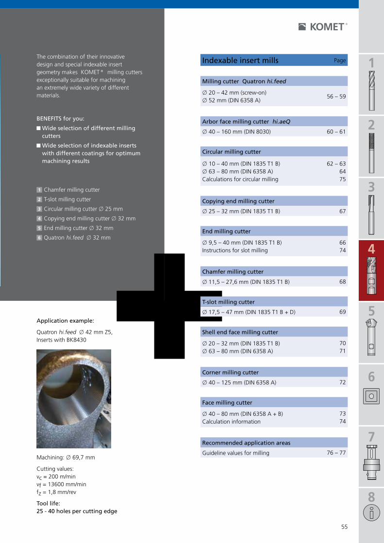
1
2
3
4
5
6
7
8
55
56 – 59
60 – 61
62 – 636475
67
6674
68
69
7071
72
7374
76 – 77
indexable insert mills Page
Milling cutter Quatron hi.feed
x 20 – 42 mm (screw-on)x 52 mm (DIN 6358 A)
Arbor face milling cutter hi.aeQ
x 40 – 160 mm (DIN 8030)
Circular milling cutter
x 10 – 40 mm (DIN 1835 T1 B)x 63 – 80 mm (DIN 6358 A)Calculations for circular milling
Copying end milling cutter
x 25 – 32 mm (DIN 1835 T1 B)
end milling cutter
x 9,5 – 40 mm (DIN 1835 T1 B)Instructions for slot milling
Chamfer milling cutter
x 11,5 – 27,6 mm (DIN 1835 T1 B)
t-slot milling cutter
x 17,5 – 47 mm (DIN 1835 T1 B + D)
shell end face milling cutter
x 20 – 32 mm (DIN 1835 T1 B)x 63 – 80 mm (DIN 6358 A)
Corner milling cutter
x 40 – 125 mm (DIN 6358 A)
face milling cutter
x 40 – 80 mm (DIN 6358 A + B)Calculation information
Recommended application areas
Guideline values for millingMachining: x 69,7 mm
Cutting values:vc = 200 m/minvf = 13600 mm/minfz = 1,8 mm/rev
tool life: 25 - 40 holes per cutting edge
The combination of their innovative design and special indexable insert geometry makes KOMET® milling cutters exceptionally suitable for machining an extremely wide variety of different materials.
Benefits for you:
Wide selection of different milling cutters
Wide selection of indexable inserts with different coatings for optimum machining results
1 Chamfer milling cutter
2 T-slot milling cutter
3 Circular milling cutter x 25 mm
4 Copying end milling cutter x 32 mm
5 End milling cutter x 32 mm
6 Quatron hi.feed x 32 mm
Application example:
Quatron hi.feed x 42 mm Z5, Inserts with BK8430

1
2
3
4
56
KOMet® Quatron hi.feed
The success enjoyed by our tried and tested KUB Quatron® solid drill range continues in our milling cutter range. With the successful Quatron indexable insert developed from solid drilling technology, we are extending our experience to the Quatron hi.feed milling cutter.
Plunge milling (also known more simply as plunging) is a type of machining particularly suitable for cutting deep grooves and large cavities. Plunge milling can be the ideal solution for large projection lengths and unstable conditions.
Application: The Quatron hi.feed is a high-performance roughing tool for the fast removal of large quantities of cut metal.
Benefits for you:
Mill cutting bores with just one tool rather than enlarging them with several drilling tools
Four cutting edges per insert lowers production costs per cutter
Increase in productivity thanks to high-volume chip removal
Deflection of passive forces in an axial direction. Plunge milling puts less stress on the spindle thanks to the lower loading
Variable manufacture of different diameters Low cutting pressure A tough substrate allows universal use for steel, cast iron and stainless materials
Capable of high feed rates – up to 2 mm per cutting edge
Ideal when producing larger drilled holes using small and low-performance machines

1
2
3
4
5
6
7
8
57
KOMet® Quatron hi.feed
X D X d1min-max
a apmax
aemax
20 30-38 2,8° 0,67 5,0
25 41-48 2,8° 0,72 5,6
32 52-62 2,5° 0,88 7,0
35 56-68 2,5° 0,88 7,0
42 69-82 2,3° 1,1 8,5
52 87-100 2,3° 1,1 8,5
ap a
x dM
ap
dM = d1max – DdM = d1min – D
x D
x d1min-max
ap
x D
x D
fzmin-max
Ymax
initial min max
0,10 0,08 0,15 < 0,7 × D
Y
Y
ae
ae/2
ae
Y
Application examples
Circular interpolation into solid material inclined plunging
Plunge millingAxial plunging
Tool offset with optimum coverage
Tool offset for unstable conditions
Milling cutter dia.
Machining dia.
Ramping angle
Cutting depth

1
2
3
4
58
Quatron hi.feed
-01
X D X d M X D1 L ap ae Z P M K N S Hmax hh
20 f51 01190 10,5 M10 10 30 0,67 5 3 15 0,06n00 56041
S/M2×4,3-6IP0,62 Nm
W83 13010.048425SOEX 050204-01 BK8425 §§§
25 f51 01200 12,5 M12 14 35 0,72 5,6 3 17 0,09n00 57553
S/M2,2×5,5-6IP1,01 Nm
W83 18010.068425SOEX 060306-01 BK8425 §§§
32 f51 01210 17 M16 18 42 0,88 7,0 4 27 0,21 n00 57571S/M2,5×6,3-8IP
1,28 Nm
W83 23010.088425SOEX 07T308-01 BK8425 §§§
35 f51 01230 17 M16 21 42 0,88 7,0 4 27 0,23
42 f51 01220 17 M16 25 42 1,1 8,5 4 27 0,26
n00 57261S3575-15IP
2,8 Nm
W83 32010.088425SOEX 090408-01 BK8425 §§§42 f51 01240 17 M16 25 42 1,1 8,5 5 27 0,25
52 f51 01250 DIN 6358 A 35 40 1,1 8,5 6 – 0,37
ap
x D
L
x dM
x D
1
8°
apx
DL
x D
1
x 2
2H7
F51 01250DIN 6358 A
8°
X 20 – 52 mm
KKK
a e
a e
KOMet® Quatron hi.feed
1
1
Width across flats AF
Z = effective number of teeth for calculating vf
Milling cutter
screw-oncentral internal coolant supplyMQL processing or with air recommended
supply includes: Milling cutter with clamping screws 1. Please order insert separately. Screwdriver see chapter 8.
Guideline values for milling: Page 59.
Basic recommendationClamping screw
1Insert for
workpiece material§ main area of application$ suitable in some cases
Order no. Af Order no. Order no. ISO codeArticle size

vc (m/min)
x 20 x 25 x 32 x 35 x 42 x 52
P1.
0
#50
0 St37-2 / 1.0037; 9SMn28 / 1.0715; St44-2 / 1.0044
2.0
500-
900 St52-2 / 1.0050,
C55 / 1.0525,16MnCr5 / 1.7131
2.1
<500 9SMnPb28 /
1.0718
3.0
>900 42CrMo4 /
1.7225,CK60 / 1.1221
4.0
>900
X6CrMo4 / 1.2341,X165CrMoV12 / 1.2601
4.1
S5.
0
250
Inconel 718 / 2.4668,Nimonic 80A / 2.4631
5.1
400
TiAl5Sn2 / 3.7114
M6.
0
#60
0 X2CrNi189 / 1.4306, X5CrNiMo1810 / 1.4401
6.1
<900
X8CrNb17 / 1.4511,X10CrNiMoTi1810 / 1.4571
7.0
>900
X10CrAl7 / 1.4713,X8CrS-38-18 / 1.4862
K8.
0
180 GG-25 / 0.6025,
GG-35 / 0.6035
8.1
250 GG-NiCr202 /
0.6660
9.0
#60
0
130
GGG-40 / 0.7040
9.1
230 GGG-50 / 0.7050
GGG-55 / 0.7055GTW-55 / 0.8055
10.0
>600
250 GGG-60 / 0.7060
GTS-65 / 0.8165
10.1
200 GGG-NiCr20-2 /
0.7661
10.2
300 GGV Ti < 0,2
GGV Ti > 0,2
N12
.0
90
CuZn36Pb3 / 2.1182,G-CuPb15Sn / 2.1182
12.1
100 CuZn40Al1 /
2.0550,E-Cu57 / 2.0060
13.0
60
AlMg1 / 3.3315,AlMnCu / 3.0517
13.1
75
G-AlMg5 / 3.3561,G-AlSi9Mg / 3.2373
14.0
100 G-AlSi10Mg /
3.2381
H15
.0
1400
16.0
1800
1
2
3
4
5
6
7
8
59
3000,5-1,2
0,05-0,11
0,5-1,2
0,05-0,11
0,5-1,6
0,06-0,13
0,5-1,6
0,06-0,13
0,5-2,0
0,07-0,15
0,5-2,0
0,07-0,15
2500,5-1,2
0,05-0,11
0,5-1,2
0,05-0,11
0,5-1,6
0,06-0,13
0,5-1,6
0,06-0,13
0,5-2,0
0,07-0,15
0,5-2,0
0,07-0,15
3000,5-1,2
0,05-0,11
0,5-1,2
0,05-0,11
0,5-1,6
0,06-0,13
0,5-1,6
0,06-0,13
0,5-2,0
0,07-0,15
0,5-2,0
0,07-0,15
2000,5-1,2
0,05-0,11
0,5-1,2
0,05-0,11
0,5-1,6
0,06-0,13
0,5-1,6
0,06-0,13
0,5-2,0
0,07-0,15
0,5-2,0
0,07-0,15
1800,5-1,2
0,05-0,11
0,5-1,2
0,05-0,11
0,5-1,6
0,06-0,13
0,5-1,6
0,06-0,13
0,5-2,0
0,07-0,15
0,5-2,0
0,07-0,15
80 0,5-1,2
0,05-0,11
0,5-1,2
0,05-0,11
0,5-1,6
0,06-0,13
0,5-1,6
0,06-0,13
0,5-2,0
0,07-0,15
0,5-2,0
0,07-0,15
KOMet® Quatron hi.feed
Guideline values for milling fz (mm/tooth)
Mat
eria
l gro
up
Stre
ngth
Rm
(N/m
m²)
Har
dnes
s H
B
Material
Material example,material code/DIN
Cutting speed
Feed
norm
al
plun
ge
mill
ing
norm
al
plun
ge
mill
ing
norm
al
plun
ge
mill
ing
norm
al
plun
ge
mill
ing
norm
al
plun
ge
mill
ing
norm
al
plun
ge
mill
ing
non-alloy steels
non-alloy /low alloy steels
lead alloys
non alloy / low alloy steels: heat resistant structural, heat treated, nitride and tools steels
high alloy steels
HSS
special alloys: Inconel, Hastelloy, Nimonic, stc.
titanium,titanium alloys
stainless steels
stainless steels
stainless / fireproof steels
gray cast iron
alloy gray cast iron
spheroidal graphite cast iron, ferritic
spheroidal graphite cast iron, ferritic /perlitic
spheroidal graphite cast iron, perlitic malleable iron
alloyed spheroidalgraphite cast iron
vermicular cast iron
copper alloy, brass,lead-alloy bronze, lead bronze:good cut
copper alloy, brass, bronze:average cut
wrought aluminium alloys
cast alum. alloy: Si-content <10%magnesium alloy
cast alum.alloy:Si-content >10%
hardened steels< 45 HRC
hardened steels> 45 HRC
Recommended application areas
Cutting values shown are maximum values relating to the basic recommendations for cutting materials given.
important: see chapter 8 for more application details and safety notes !
on request
on request

1
2
3
4
60
KOMet® hi.aeQ X 40 – 160 mm
1
2 3
23
1
1
2
x D
L
x d
x d
1
88°
x D
Lx
d
x d
1
88°
x D
L
x d
x d
1
88°
x d2
The innovative hi.aeQ arbor face milling cutter is excellently suited for reliable face milling of cast iron materials. It features a high number of teeth and low cutting forces.
The Q80 tangential indexable inserts used are designed for counterboring and milling operations. Thanks to a standing-lying arrangement, each insert has eight usable cutting edges. The extremely stable tangential indexable inserts, when combined with selected cutting tool materials and coatings, provide a great economic advantage when machining cast iron materials.
Arbor face milling cutter
DIN 8030 form B
DIN 8030 form A
DIN 8030 form C
Benefits for you:
High stability for high cutting efficiency thanks to the use of tangential screw-fit Q80 indexable inserts
Eight usable cutting edges thanks to indexable inserts which are fitted in an alternately standing and lying arrangement
Low power consumption thanks to low cutting forces and a low-vibration, quiet milling characteristic re-duces the spindle loads
This concept guarantees extremely high process reliability when combined with modern, matched substrates and coatings
Both PVD and CVD-coated indexable inserts are available
If internal coolant supply is used, optimum cool-ing of every cutting edge is achieved by using the coolant sleeve

21
1
2
1
2
3
4
5
6
7
8
61
hi.aeQ
DIN8030
X D X dH6 X d1 X d2 L ap Z P M K N S Hmax
40 f51 14040 A 16 36 – 40 3 6 0,36 n00 57251S3076-8IP2,25 Nm
Q80 20050.062715LNGU 090406 EN-05 BK2715
Q80 20050.066115LNGU 090406 EN-05 BK6115
§
§50 f51 14050 A 22 41 – 40 3 8 0,36
63 f51 14060 A 22 48 – 40 4 8 0,52
n00 57411S4010-15IP
4,3 Nm
Q80 32000.012715LNGU 120508 EN-05 BK2715
Q80 32000.016115LNGU 120508 EN-05 BK6115
§
§
80 f51 14080 B 27 60 – 50 4 10 0,99
100 f51 14100 B 32 78 – 50 4 12 1,71
125 f51 14120 B 40 100 – 63 4 16 3,53
160 f51 14160 C 40 140 66,7 63 4 20 5,66
X D
40 L01 01020 0,05 55011 08025
50 L01 01030 0,05 55011 10025
63 L01 01040 0,022 55011 10025
80 L01 01050 0,152 55011 12040
100 L01 01060 0,170 55011 16030
125 L01 01070 0,396 55011 20040
160 – 55011 12040
KOMet® hi.aeQ
Arbor face milling cutter
Z = effective number of teeth for calculating vf
Guideline values for milling: Page 76-77.
Application example
Workpiece: Reinforcing ringMaterial: EN-GJS -400-18V-LTMachine: DMC 340 FD vc = 200 m/minn = 509 rev/minfz = 0,3 mmf = 4,8 mm/revvf = 2445 mm/minap = 4 mm
Quiet and quick machining
supply includes milling cutter X 40 - 63 mm: with clamping screws 1 and cylindrical screw 2.supply includes milling cutter X 80 - 160 mm: with clamping screws 1.
supply includes coolant sleeve 3: with cylindrical screw 2.
Please order inserts separately. Screwdriver see chapter 8.
Basic recommendationClamping screw
1Insert for
workpiece materialBolt-hold circle
§ main area of application$ suitable in some cases
Order no. form Order no. Order no.Article ISO code
Coolant sleeve 3 Cylindrical screw 2
Order no. Order no.
8 usable cutting edges per indexable insert

1
2
3
4
62
X 10 – 16 mm
X D bH13 a X D1 X dh6 L L1 P M K N S Hhh
10 f51 70050 1,1 0,9 8,2 16 84 24 0,09n00 57221S2553-7IP
0,9 Nm
Q12 18000.108425Q12 18000.102715Q12 18000.1022
TPAX1102ZZ R-110 BK8425TPAX1102ZZ R-110 BK2715TPAX1102ZZ R-110 K20
§§§§
16 f51 700801,11,31,6
0,91,31,4
13 16 84 24 0,11n00 57281S3598-15IP
2,8 Nm
Q12 32000. .. 8425Q12 32000. .. 2715Q12 32000. .. 22
TCAX16T3ZZ R- ... BK8425TCAX16T3ZZ R- ... BK2715TCAX16T3ZZ R- ... K20
§§§§
15 b = 1,1 mm 11016 b = 1,3 mm 13017 b = 1,6 mm 160
KOMet®
KKK
L1
Lb
a
x D
1
x d
x D 1
Circular milling cutter Basic recommendationClampingscrew 1
Insert for workpiece material§ main area of application$ suitable in some cases
Order no. Order no.Article
Order no. ISO-Codesize
Circular milling cutter
Design:The dimension b is determined by the slot widths with H13 tolerance for holding rings to DIN 471 and DIN 472; this is the higher tolerance limit for the slot widths which can be produced.
central coolant supplycylindrical shank to DIN 1835 T1 Bcalculations for circular milling see page 75
y = number of inserts = 1z = effective number of teeth for calculating vf = 3
For further details on selecting insert types, see chapter 6.
supply includes: Circular milling cutter with clamping screw 1. Please order insert separately. Screwdriver see chapter 8.Copaslip grease for screw should be included in first order. Order No. 4700100100.
Guideline values for milling: Page 76-77.

1
2
3
4
5
6
7
8
63
Q12 18000.36..Q12 32000.38..
R
0,05×45°
R
0,05×45°
0,05×45°
L1
Lb
a
x D
1
x d
x D
X 25 – 40 mm
.36..
X D bH13 a R X D1 X dh6 L L1 P M K N S Hhh
25 f51 701211,6
1,851,01,25
0,10,1
20,5 25 100 42 0,35n00 57221S2553-7IP
0,9 Nm
Q12 18000. ..8425Q12 18000. ..2715Q12 18000. ..22
TNAX1103ZZ R-... BK8425TNAX1103ZZ R-... BK2715TNAX1103ZZ R-... K20
§§§§
25 f51 701402,152,65
1,51,75
0,10,2
20,5 25 100 42 0,30
31 b = 1,6 mm 16032 b = 1,85 mm 18533 b = 2,15 mm 21534 b = 2,65 mm 26536 b = 2,65 mm 265
KOMet®
KKK
b
a
.38..
X D bH13 a R X D1 X dh6 L L1 P M K N S Hhh
40 f51 702012,653,154,15
1,751,752,5
0,20,20,3
33 32 110 49,5 0,65n00 57281S3598-15IP
2,8 Nm
Q12 32000. ..8425Q12 32000. ..2715Q12 32000. ..22
TNAX1604ZZ R-... BK8425TNAX1604ZZ R-... BK2715TNAX1604ZZ R-... K20
§§§§
41 b = 2,65 mm 26542 b = 3,15 mm 31543 b = 4,15 mm 41538 b = 4,15 mm 415
1
Circular milling cutter
central coolant supplycylindrical shank to DIN 1835 T1 B
calculations for circular milling see page 75
Design:The dimension b is determined by the slot widths with H13 tolerance for holding rings to DIN 471 and DIN 472; this is the higher tolerance limit for the slot widths which can be produced.
y = number of inserts = 3z = effective number of teeth for calculating vf = 3
Guideline values for milling: Page 76-77.
Circular milling cutter Basic recommendationClampingscrew 1
Insert for workpiece material§ main area of application$ suitable in some cases
Order no. Order no.Article
Order no. ISO-Codesize
Circular milling cutter Basic recommendationClampingscrew 1
Insert for workpiece material§ main area of application$ suitable in some cases
Order no. Order no.Article
Order no. ISO-Codesize
For further details on selecting insert types, see chapter 6.
supply includes: Circular milling cutter with clamping screws 1. Please order inserts separately. Screwdriver see chapter 8.Copaslip grease for screw should be included in first order. Order No. 4700100100.
For further details on selecting insert types, see chapter 6.

1
2
3
4
64
.38..
X D b a R X dH7 X d1 L P M K N S Hhh
63 f51 710312,653,154,15
1,751,752,5
0,20,20,3
22 55 40 0,63n00 57281S3598-15IP
2,8 Nm
Q12 32000. ..8425Q12 32000. ..2715Q12 32000. ..22
TNAX1604ZZ R-... BK8425TNAX1604ZZ R-... BK2715TNAX1604ZZ R-... K20
§§§§
41 b = 2,65 mm 26542 b = 3,15 mm 31543 b = 4,15 mm 41538 b = 4,15 mm 415
X 63 – 80 mmKOMet®
KK
.87..
X D b a R X dH7 X d1 L P M K N S Hhh
80 f51 711014,154,655,15
2,53,44,0
0,3 27 68 50 1,25n00 57281S3598-15IP
2,8 Nm
Q12 44000. ..8425Q12 44000. ..2715Q12 44000. ..22
TNAX2206ZZ R-... BK8425TNAX2206ZZ R-... BK2715TNAX2206ZZ R-... K20
§§§§
84 b = 4,15 mm 41585 b = 4,65 mm 46586 b = 5,15 mm 51587 b = 5,15 mm 515
L
a
x d
1
x d
x D
Ra
Q12 32000.38..Q12 44000.87..
0,05×45°
0,05×45°
0,05×45°
b b
R
1
Circular milling cutter
location to DIN 6358 Acalculations for circular milling see page 75
Design:The dimension b is determined by the slot widths with H13 tolerance for holding rings to DIN 471 and DIN 472; this is the higher tolerance limit for the slot widths which can be produced.
y = number of inserts = 6z = effective number of teeth for calculating vf = 6
Guideline values for milling: Page 76-77.
Circular milling cutter Basic recommendationClampingscrew 1
Insert for workpiece material§ main area of application$ suitable in some cases
Order no. Order no.Article
Order no. ISO-Codesize
Circular milling cutter Basic recommendationClampingscrew 1
Insert for workpiece material§ main area of application$ suitable in some cases
Order no. Order no.Article
Order no. ISO-Codesize
For further details on selecting insert types, see chapter 6.
supply includes: Circular milling cutter with clamping screws 1. Please order inserts separately. Screwdriver see chapter 8.Copaslip grease for screw should be included in first order. Order No. 4700100100.
For further details on selecting insert types, see chapter 6.

1
2
3
4
5
6
7
8
65
b =
a =
R =
max. 0,2
a =
b =
a2 =
a2
=
a1 =
a1 =
R2 =
R1 =
b a max. R a
XQ12 18... 1,60 – 2,65 2,2 0,1 – 0,5 30° – 60°
XQ12 32... 2,65 – 4,15 3,2 0,1 – 0,5 30° – 60°
XQ12 44... 4,15 – 5,80 5,2 0,1 – 0,5 30° – 60°
b a1 a2 R1 / R2 a1 / a2
XQ12 18... 1,60 – 2,65 2,5 2,2 0,0 –
b2
15° – 75°
XQ12 32... 2,65 – 4,15 3,5 3,2 0,0 –
b2
30° – 60°
XQ12 44... 4,15 – 5,80 5,5 5,2 0,0 –
b2
30° – 60°
fax to +49 7143 373577
Please provide workpiece sketch !
Quantity:
This order is subject to the KOMET GROUP GmbH conditions of supply and payment.
Order No. / Order date
Company:
Adress:
Please state Customer No. KOMET internalSignature
n Order n inquiry
Material to be machined:
Contact:
Department:
Phone:
fax:
e-Mail:
symmetrical
asymmetrical
KOMet® special grooving inserts
Parameters
Insert size
Groove width
Groove depth
Radius Chamfer angle
Parameters
Insert size
Groove width
Groove depth
Radius Chamfer angle

1
2
3
4
66
X D Xdh6 L L1 a y z P M K N S Hhh
9,5 f51 50251 16 80 17 9 1 1 0,09
n00 57321S2556-8IP1,28 Nm
Q36 18000.01.. APKT 1003PD-R ... §§§§§
10,0 f51 50052 16 80 17 9 1 1 0,09
12,0 f51 50062 16 80 21 9 1 1 0,09
14,0 f51 50072 16 80 23 9 1 1 0,10
16,0 f51 50082 16 85 26 9 2 2 0,10
20,0 f51 50102 20 90 26 9 3 3 0,18
25,0 f51 50122 25 100 32 11 3 3 0,31 n00 57341S3066-9IP2,25 Nm
Q36 24000.02.. APKT 1203PD-R ... §§§§§32,0 f51 50162 25 100 42 11 4 4 0,35
40,0 f51 50181 32 115 40 11 3 3 0,57n00 57411S40101-15IP
4,3 NmQ36 38000.07.. APKT 1605PD-RM ...§§§§§
X 9,5 – 40 mmKOMet®
KKK
X D Xdh6 L L1 a y z P M K N S Hhh
20,0 f51 50410 20 126 75 11 2 2 0,24 n00 57341S3066-9IP2,25 Nm
Q36 24000.02.. APKT 1203PD-R ... §§§§§25,0 f51 50420 25 142 85 11 3 3 0,44
32,0 f51 50460 32 182 120 11 3 3 0,91
L1
L
a
x d
x D
L1
L
a
x d
h6
x d
1
1
1
y = number of insertsz = effective number of teeth for calculating vf
end milling cutter
central coolant supplycylindrical shank to DIN 1835 T1 Binstructions for slot milling see page 74
Guideline values for milling: Page 76-77.
end milling cutter Basic recommendationClampingscrew 1
Insert for workpiece material§ main area of application$ suitable in some cases
Order no. Order no.Article
Order no. ISO Codesize
end milling cutter Basic recommendationClampingscrew 1
Insert for workpiece material§ main area of application$ suitable in some cases
Order no. Order no.Article
Order no. ISO Codesize
For further details on selecting insert types, see chapter 6.
supply includes: End milling cutter with clamping screws 1. Please order inserts separately. Screwdriver see chapter 8.Copaslip grease for screw should be included in first order. Order No. 4700100100.

1
2
3
4
5
6
7
8
67
L1
L
a
X 25 – 32 mm KOMet®
KK
X D Xdh6 L L1 a y z P M K N S Hhh
25 f51 50620 25 100 32 11 3 3 0,30 n00 57341S3066-9IP2,25 Nm
Q36 24000.04..Q36 24000.05..Q36 24000.06..
APKT 120316PD-R ...APKT 120324PD-R ...APKT 120332PD-R ...
§§§
§§§
§§§
§§§32 f51 50660 25 100 42 11 4 4 0,37
x d
x D
1
Copying end milling cutter
central coolant supplycylindrical shank to DIN 1835 T1 B
y = number of insertsz = effective number of teeth for calculating vf
Copying end milling cutter Basic recommendationClampingscrew 1
Insert for workpiece material§ main area of application$ suitable in some cases
Order no. Order no.Article
Order no. ISO Codesize
For further details on selecting insert types, see chapter 6.
supply includes: Copying end milling cutter with clamping screws 1. Please order inserts separately. Screwdriver see chapter 8.Copaslip grease for screw should be included in first order. Order No. 4700100100.
Guideline values for milling: Page 76-77.

1
2
3
4
68
X D X D1 Xdh6 XD2 L L1 y z P M K N S Hhh
19,6 11,5 f53 30110 16 11 80 29 1 1 0,10 n00 57221S2553-7IP
0,9 Nm
Q09 18000.172725Q09 18000.1722Q09 18000.1787
SPMT060304 BK2725SPMT060304 K20SPMT060304 BK87
§
§
§§§§
27,6 19,5 f53 30191 25 19 90 31 2 2 0,28
X 11,5 – 27,6 mmKOMet®
KK
L1
L
90°
x d
x D
1
x D
x D
21
Chamfer milling cutter
cylindrical shank to DIN 1835 T1 Breverse circular milling possible
y = number of insertsz = effective number of teeth for calculating vf
Chamfer milling cutter Basic recommendationClampingscrew 1
Insert for workpiece material§ main area of application$ suitable in some cases
Order no. Order no.Article
Order no. ISO Codesize
For further details on selecting insert types, see chapter 6.
supply includes: Chamfer milling cutter with clamping screws 1. Please order inserts separately. Screwdriver see chapter 8.Copaslip grease for screw should be included in first order. Order No. 4700100100.
Guideline values for milling: Page 76-77.
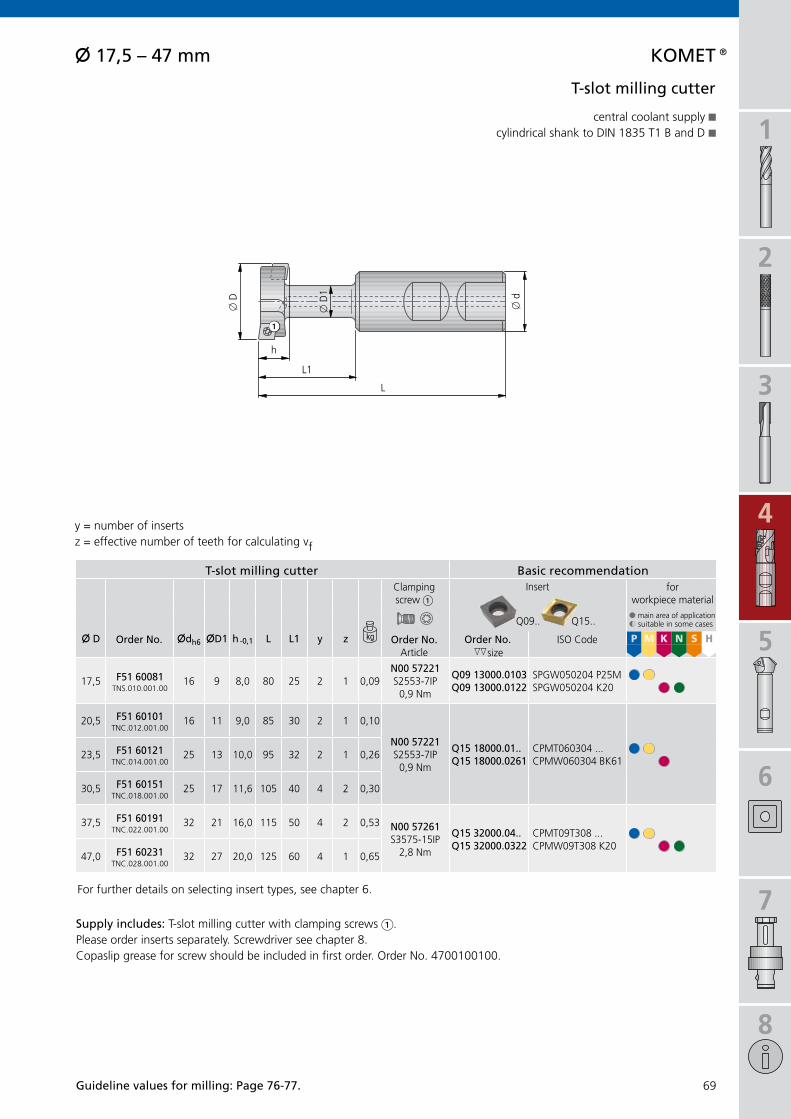
1
2
3
4
5
6
7
8
69
L1
L
h
x d
x D
1
x D
Q09.. Q15..
X D Xdh6 XD1 h -0,1 L L1 y z P M K N S Hhh
17,5 f51 60081TNS.010.001.00
16 9 8,0 80 25 2 1 0,09n00 57221S2553-7IP
0,9 Nm
Q09 13000.0103Q09 13000.0122
SPGW050204 P25MSPGW050204 K20
§§§§
20,5 f51 60101TNC.012.001.00
16 11 9,0 85 30 2 1 0,10
n00 57221S2553-7IP
0,9 Nm
Q15 18000.01..Q15 18000.0261
CPMT060304 ...CPMW060304 BK61
§§§23,5 f51 60121
TNC.014.001.0025 13 10,0 95 32 2 1 0,26
30,5 f51 60151TNC.018.001.00
25 17 11,6 105 40 4 2 0,30
37,5 f51 60191TNC.022.001.00
32 21 16,0 115 50 4 2 0,53 n00 57261S3575-15IP
2,8 Nm
Q15 32000.04..Q15 32000.0322
CPMT09T308 ...CPMW09T308 K20
§§§§
47,0 f51 60231TNC.028.001.00
32 27 20,0 125 60 4 1 0,65
X 17,5 – 47 mm KOMet®
KK
1
t-slot milling cutter
central coolant supplycylindrical shank to DIN 1835 T1 B and D
y = number of insertsz = effective number of teeth for calculating vf
Guideline values for milling: Page 76-77.
t-slot milling cutter Basic recommendationClampingscrew 1
Insert for workpiece material§ main area of application$ suitable in some cases
Order no. Order no.Article
Order no. ISO Codesize
For further details on selecting insert types, see chapter 6.
supply includes: T-slot milling cutter with clamping screws 1. Please order inserts separately. Screwdriver see chapter 8.Copaslip grease for screw should be included in first order. Order No. 4700100100.

1
2
3
4
70
X D Xdh6 L L1 a y z P M K N S Hhh
20 f51 40300* 25 100 33 27 6 2 0,26n00 57321S2556-8IP1,28 Nm
Q36 18000.01.. APKT 1003PD-R ... §§§§§20 f51 40310 25 90 24 18 4 2 0,25
25 f51 40320 25 100 41 27 6 2 0,29
32 f51 40360 32 110 49 26 12 3 0,53
X 20 – 32 mmKOMet®
KK
L1
L
a
x d
x D
1
shell end face milling cutter
central coolant supplycylindrical shank to DIN 1835 T1 B
* only suitable for edge cutting
y = number of insertsz = effective number of teeth for calculating vf
Guideline values for milling: Page 76-77.
shell end face milling cutter Basic recommendationClampingscrew 1
Insert for workpiece material§ main area of application$ suitable in some cases
Order no. Order no.Article
Order no. ISO Codesize
For further details on selecting insert types, see chapter 6.
supply includes: Shell end face milling cutter with clamping screws 1. Please order inserts separately. Screwdriver see chapter 8.Copaslip grease for screw should be included in first order. Order No. 4700100100.

1
2
3
4
5
6
7
8
71
X D XdH7 L a y z P M K N S Hhh
63 f51 42060 27 60 42 9 3 0,71 n00 57411S40101-15IP
4,3 NmQ36 38000.07.. APKT 1605PD-R ... §§§§§
80 f51 42080 32 70 55 16 4 0,39
X 63 – 80 mm KOMet®
KK
a
L
x d
x D
1
shell end face milling cutter
central coolant supplylocation to DIN 6358 A
y = number of insertsz = effective number of teeth for calculating vf
Guideline values for milling: Page 76-77.
shell end face milling cutter Basic recommendationClampingscrew 1
Insert for workpiece material§ main area of application$ suitable in some cases
Order no. Order no.Article
Order no. ISO Codesize
For further details on selecting insert types, see chapter 6.
supply includes: Shell end face milling cutter with clamping screws 1. Please order inserts separately. Screwdriver see chapter 8.Copaslip grease for screw should be included in first order. Order No. 4700100100.

1
2
3
4
72
X 40 – 125 mmKOMet®
KK
X D XdH7 L a y z P M K N S Hhh
40 f51 12040 22 40 11 4 4 0,18n00 57341S3066-9IP2,25 Nm
Q36 24000.02.. APKT 1203PD-R ... §§§§§50 f51 12050 22 40 11 4 4 0,28
63 f51 12060 22 40 11 5 5 0,54
80 f51 12180 27 50 11 6 6 1,19
80 f51 12080 27 50 15 5 5 1,13 n00 57411S40101-15IP
4,3 NmQ36 38000.07.. APKT 1605PD-R ... §§§§§100 f51 12100 32 50 15 6 6 1,91
125 f51 12120 40 63 15 7 7 4,00
L
a
x d
x D
1
Corner milling cutter
central coolant supplylocation to DIN 6358 A
y = number of insertsz = effective number of teeth for calculating vf
Guideline values for milling: Page 76-77.
Corner milling cutter Basic recommendationClampingscrew 1
Insert for workpiece material§ main area of application$ suitable in some cases
Order no. Order no.Article
Order no. ISO Codesize
For further details on selecting insert types, see chapter 6.
supply includes: Corner milling cutter with clamping screws 1. Please order inserts separately. Screwdriver see chapter 8.Copaslip grease for screw should be included in first order. Order No. 4700100100.

1
2
3
4
5
6
7
8
73
X D X D1 XdH7 L a y z P M K N S Hhh
40 53 PFS.040.001.79 f51 01040 16 40 6 3 3 0,38n00 57301S45100-20IP
6,25 Nm
Q09 44000. ..SEHW 1204 ... §§§§
50 63 PFS.050.001.79 f51 01050 22 40 6 4 4 0,46
63 76 PFS.063.001.79 f51 01060 22 40 6 4 4 0,67
80 93 PFS.080.001.79 f51 01080 27 50 6 5 5 1,17
L
a45°
x d
x D
x D
1
X 40 – 80 mm KOMet®
K
1
location to DIN 6358 A and B
face milling cutter
y = number of insertsz = effective number of teeth for calculating vf
Guideline values for milling: Page 76-77.
For further details on selecting insert types, see chapter 6.
supply includes: Face milling cutter with clamping screws 1. Please order inserts separately. Screwdriver see chapter 8.Copaslip grease for screw should be included in first order. Order No. 4700100100.
face milling cutter Basic recommendationClampingscrew 1
Insert for workpiece material§ main area of application$ suitable in some cases
Article Order no. Order no.Article
Order no.size
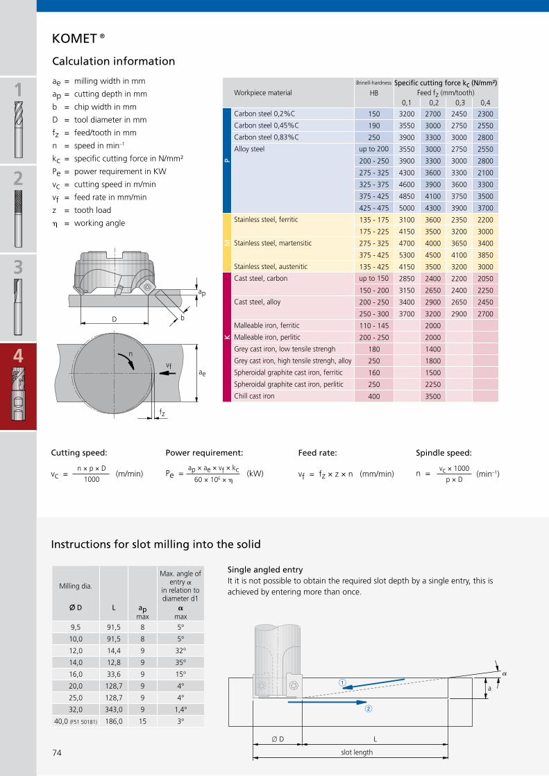
1
2
3
4
74
D
ap
b
aevf
n
fz
vf = fz × z × n (mm/min)
ae =
ap =
b =
D =
fz =
n =
kc =
Pe =
vc =
vf =
z =
=
KOMet®
n =vc × 1000
p × D(min–1)vc =
n × p × D
1000(m/min)
ap × ae × vf × kc60 × 106 ×
Pe = (kW)
HB0,1 0,2 0,3 0,4
P
150 3200 2700 2450 2300
190 3550 3000 2750 2550
250 3900 3300 3000 2800
3550 3000 2750 2550
200 - 250 3900 3300 3000 2800
275 - 325 4300 3600 3300 2100
325 - 375 4600 3900 3600 3300
375 - 425 4850 4100 3750 3500
425 - 475 5000 4300 3900 3700
M135 - 175 3100 3600 2350 2200
175 - 225 4150 3500 3200 3000
275 - 325 4700 4000 3650 3400
375 - 425 5300 4500 4100 3850
135 - 425 4150 3500 3200 3000
K
2850 2400 2200 2050
150 - 200 3150 2650 2400 2250
200 - 250 3400 2900 2650 2450
250 - 300 3700 3200 2900 2700
110 - 145 2000
200 - 250 2000
180 1400
250 1800
160 1500
250 2250
400 3500
X D L ap amax max
9,5 91,5 8 5°
10,0 91,5 8 5°
12,0 14,4 9 32°
14,0 12,8 9 35°
16,0 33,6 9 15°
20,0 128,7 9 4°
25,0 128,7 9 4°
32,0 343,0 9 1,4°
40,0 (F51 50181) 186,0 15 3°
��
�
�
�
�
a
Lx D
feed rate: spindle speed:Cutting speed: Power requirement:
milling width in mm
cutting depth in mm
chip width in mm
tool diameter in mm
feed/tooth in mm
speed in min–1
specific cutting force in N/mm²
power requirement in KW
cutting speed in m/min
feed rate in mm/min
tooth load
working angle
Calculation information
Workpiece materialBrinell-hardness specific cutting force kc (n/mm²)
Feed fz (mm/tooth)
Carbon steel 0,2%C
Carbon steel 0,45%C
Carbon steel 0,83%C
Alloy steel up to 200
Stainless steel, ferritic
Stainless steel, martensitic
Stainless steel, austenitic
Cast steel, carbon up to 150
Cast steel, alloy
Malleable iron, ferritic
Malleable iron, perlitic
Grey cast iron, low tensile strengh
Grey cast iron, high tensile strengh, alloy
Spheroidal graphite cast iron, ferritic
Spheroidal graphite cast iron, perlitic
Chill cast iron
instructions for slot milling into the solid
Milling dia.
Max. angle of entry
in relation to diameter d1
single angled entryIt it is not possible to obtain the required slot depth by a single entry, this is achieved by entering more than once.
slot length

1
2
3
4
5
6
7
8
75
KOMet®
aeDa² – Di²
4 (Da – Dwz)=
vf(Da – Dwz) × n × zeff × fz
Da=
Da
DiDwz
aeD
a
Di Dwz
ae
aeDa² – Di²
4 (Di – Dwz)=
vf(Di – Dwz) × n × zeff × fz
Di=
��
�
�
�
�
a –0,8
0,8
important: see chapter 8 for more application details and safety notes!
The average chip thickness is determined by considering workpiece and tool geometry data. The total cutting time must allow for the entry and exit times. Axial "chambering" is also possible with these interpolating milling cutters.
Circular milling, internal
Circular milling, external
R = workpiece radius in mmr = milling cutter radius in mmar = radial cutting depth in mm = approach angle in °hm = average chip thickness in mmn = spindle speed in min–1
z = number of teeth (effectively cutting)
Calculations for circular milling
Multiple entryIt should be noted that there must be an allowance of 0,8 mm when the milling cutter is reversed. If this allowance is not made, the tool may be damaged or destroyed.
ae > radial material removal
radial
materia
l removal
ae < radial material removal
radial
materia
l removal
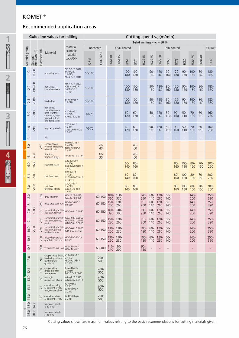
Cermet
P25M
K10
/ K
20
BK61
10
BK61
15
BK64
BK74
BK27
15
BK27
25
BK27
30
BK68
BK78
BK80
BK84
25
BK84
40
CK
37
P1.
0
#50
0 St37-2 / 1.0037; 9SMn28 / 1.0715; St44-2 / 1.0044
2.0
500-
900 St52-2 / 1.0050,
C55 / 1.0525,16MnCr5 / 1.7131
2.1
<500 9SMnPb28 /
1.0718
3.0
>900 42CrMo4 /
1.7225,CK60 / 1.1221
4.0
>900
X6CrMo4 / 1.2341,X165CrMoV12 / 1.2601
4.1
S5.
0
250
Inconel 718 / 2.4668,Nimonic 80A / 2.4631
5.1
400
TiAl5Sn2 / 3.7114
M6.
0
#60
0 X2CrNi189 / 1.4306, X5CrNiMo1810 / 1.4401
6.1
<900
X8CrNb17 / 1.4511,X10CrNiMoTi1810 / 1.4571
7.0
>900
X10CrAl7 / 1.4713,X8CrS-38-18 / 1.4862
K8.
0
180 GG-25 / 0.6025,
GG-35 / 0.6035
8.1
250 GG-NiCr202 /
0.6660
9.0
#60
0
130
GGG-40 / 0.7040
9.1
230 GGG-50 / 0.7050
GGG-55 / 0.7055GTW-55 / 0.8055
10.0
>600
250 GGG-60 / 0.7060
GTS-65 / 0.8165
10.1
200 GGG-NiCr20-2 /
0.7661
10.2
300 GGV Ti < 0,2
GGV Ti > 0,2
N12
.0
90
CuZn36Pb3 / 2.1182,G-CuPb15Sn / 2.1182
12.1
100 CuZn40Al1 /
2.0550,E-Cu57 / 2.0060
13.0
60
AlMg1 / 3.3315,AlMnCu / 3.0517
13.1
75
G-AlMg5 / 3.3561,G-AlSi9Mg / 3.2373
14.0
100 G-AlSi10Mg /
3.2381
H15
.0
1400
16.0
1800
1
2
3
4
76
60-100 100-180
100-180
90-160
120-180
90-160
120-180
90-160
100-180
80-160
180-350
60-100 100-180
100-180
90-160
120-180
90-160
120-180
90-160
100-180
80-160
180-350
60-100 100-180
100-180
90-160
120-180
90-160
120-180
90-160
100-180
80-160
180-350
40-70 60-120
60-120
50-110
120-160
50-110
90-160
50-110
70-130
60-110
160-280
40-70 60-120
60-120
50-110
120-160
50-110
90-160
50-110
70-130
60-110
160-280
– – – – – – – – – – –
20-40
40-60
10-30
40-60
60-140
80-160
80-160
100-180
80-160
70-150
200-260
60-140
80-160
80-160
100-180
80-160
70-150
200-260
60-140
80-160
80-160
100-180
80-160
70-150
200-260
60-150 180-350
150-330
140-250
60-140
120-260
60-140
140-200
250-320
60-150 150-280
120-260
110-200
60-140
120-260
60-140
140-200
250-320
60-150 160-320
140-300
130-230
60-140
120-260
60-140
140-200
250-320
60-150 150-280
120-260
110-200
60-140
120-260
60-140
140-200
250-320
60-150 130-250
110-230
100-180
60-140
120-260
60-140
140-200
250-320
60-150 130-250
110-230
100-180
60-140
120-260
60-140
140-200
250-320
60-100 110-210
90-200
90-150 – – – – –
200-500
200-500
200-500
200-500
200-500
KOMet®
Guideline values for milling Cutting speed vc (m/min)
Mat
eria
l gro
up
Stre
ngth
Rm
(N/m
m²)
Har
dnes
s H
B
Material
Material example,material code/DIN
t-slot milling = vc – 50 %
uncoated CVD coated PVD coated
non-alloy steels
non-alloy /low alloy steels
lead alloys
non alloy / low alloy steels: heat resistant structural, heat treated, nitride and tools steels
high alloy steels
HSS
special alloys: Inconel, Hastelloy, Nimonic, stc.
titanium,titanium alloys
stainless steels
stainless steels
stainless / fireproof steels
gray cast iron
alloy gray cast iron
spheroidal graphite cast iron, ferritic
spheroidal graphite cast iron, ferritic /perlitic
spheroidal graphite cast iron, perlitic malleable iron
alloyed spheroidalgraphite cast iron
vermicular cast iron
copper alloy, brass,lead-alloy bronze, lead bronze:good cut
copper alloy, brass, bronze:average cut
wrought aluminium alloys
cast alum. alloy: Si-content <10%magnesium alloy
cast alum.alloy:Si-content >10%
hardened steels< 45 HRC
hardened steels> 45 HRC
Recommended application areas
Cutting values shown are maximum values relating to the basic recommendations for cutting materials given.

Q09 Q12 Q15 Q36 Q80
P1.
0
#50
0 St37-2 / 1.0037; 9SMn28 / 1.0715; St44-2 / 1.0044
0,08-0,40
0,04-0,12
0,05-0,20
0,05-0,12
0,04-0,12
0,08-0,35
0,06-0,30
0,06-0,30
0,06-0,30
2.0
500-
900 St52-2 / 1.0050,
C55 / 1.0525,16MnCr5 / 1.7131
0,08-0,40
0,04-0,12
0,05-0,20
0,05-0,12
0,04-0,12
0,08-0,35
0,06-0,30
0,06-0,30
0,06-0,30
2.1
<500 9SMnPb28 /
1.07180,08-0,40
0,04-0,12
0,05-0,20
0,05-0,12
0,04-0,12
0,08-0,35
0,06-0,30
0,06-0,30
0,06-0,30
3.0
>900 42CrMo4 /
1.7225,CK60 / 1.1221
0,08-0,30
0,04-0,12
0,05-0,20
0,05-0,12
0,04-0,12
0,08-0,25
0,06-0,25
0,06-0,25
0,06-0,25
4.0
>900
X6CrMo4 / 1.2341,X165CrMoV12 / 1.2601
0,05-0,25
0,04-0,12
0,05-0,20
0,05-0,12
0,04-0,12
0,08-0,25
0,06-0,25
0,06-0,25
0,06-0,25
4.1 – – – – – – – – –
S5.
0
250
Inconel 718 / 2.4668,Nimonic 80A / 2.4631
0,05-0,20
0,04-0,10
0,04-0,10
0,04-0,10
5.1
400
TiAl5Sn2 / 3.7114 0,05-0,20
0,04-0,10
0,04-0,10
0,04-0,10
M6.
0
#60
0 X2CrNi189 / 1.4306, X5CrNiMo1810 / 1.4401
0,05-0,20
0,05-0,20
0,05-0,10
0,05-0,15
0,05-0,15
0,05-0,15
0,05-0,15
6.1
<900
X8CrNb17 / 1.4511,X10CrNiMoTi1810 / 1.4571
0,05-0,20
0,05-0,20
0,05-0,10
0,05-0,15
0,05-0,15
0,05-0,15
0,05-0,15
7.0
>900
X10CrAl7 / 1.4713,X8CrS-38-18 / 1.4862
0,05-0,20
0,05-0,20
0,05-0,10
0,05-0,15
0,05-0,15
0,05-0,15
0,05-0,15
K8.
0
180 GG-25 / 0.6025,
GG-35 / 0.60350,08-0,40
0,04-0,15
0,05-0,20
0,05-0,15
0,04-0,15
0,10-0,30
0,10-0,30
0,10-0,30
0,10-0,30
0,25-0,35
8.1
250 GG-NiCr202 /
0.66600,08-0,40
0,04-0,15
0,05-0,20
0,05-0,15
0,04-0,15
0,10-0,30
0,10-0,30
0,10-0,30
0,10-0,30
0,25-0,35
9.0
#60
0
130
GGG-40 / 0.7040 0,08-0,40
0,04-0,15
0,05-0,20
0,05-0,15
0,04-0,15
0,10-0,30
0,10-0,30
0,10-0,30
0,10-0,30
0,25-0,35
9.1
230 GGG-50 / 0.7050
GGG-55 / 0.7055GTW-55 / 0.8055
0,08-0,30
0,04-0,15
0,05-0,20
0,05-0,15
0,04-0,15
0,10-0,30
0,10-0,30
0,10-0,30
0,10-0,30
0,25-0,35
10.0
>600
250 GGG-60 / 0.7060
GTS-65 / 0.81650,08-0,30
0,04-0,15
0,05-0,20
0,05-0,15
0,04-0,15
0,10-0,30
0,10-0,30
0,10-0,30
0,10-0,30
0,25-0,35
10.1
200 GGG-NiCr20-2 /
0.76610,08-0,30
0,04-0,15
0,05-0,20
0,05-0,15
0,04-0,15
0,10-0,30
0,10-0,30
0,10-0,30
0,10-0,30
0,25-0,35
10.2
300 GGV Ti < 0,2
GGV Ti > 0,20,08-0,30
0,04-0,15
0,05-0,20
0,05-0,15
0,04-0,15
0,10-0,30
0,10-0,30
0,10-0,30
0,10-0,30
0,25-0,35
N12
.0
90
CuZn36Pb3 / 2.1182,G-CuPb15Sn / 2.1182
0,05-0,40
0,05-0,15
0,05-0,20
0,05-0,25
0,05-0,15
0,10-0,45
0,10-0,45
0,10-0,45
0,10-0,45
12.1
100 CuZn40Al1 /
2.0550,E-Cu57 / 2.0060
0,05-0,30
0,05-0,15
0,05-0,20
0,05-0,25
0,05-0,15
0,10-0,45
0,10-0,45
0,10-0,45
0,10-0,45
13.0
60
AlMg1 / 3.3315,AlMnCu / 3.0517
0,05-0,30
0,05-0,15
0,05-0,20
0,05-0,25
0,05-0,15
0,10-0,45
0,10-0,45
0,10-0,45
0,10-0,45
13.1
75
G-AlMg5 / 3.3561,G-AlSi9Mg / 3.2373
0,10-0,50
0,05-0,15
0,05-0,20
0,05-0,25
0,05-0,15
0,10-0,45
0,10-0,45
0,10-0,45
0,10-0,45
14.0
100 G-AlSi10Mg /
3.23810,10-0,50
0,05-0,15
0,05-0,20
0,05-0,25
0,05-0,15
0,10-0,45
0,10-0,45
0,10-0,45
0,10-0,45
H15
.0
1400
16.0
1800
1
2
3
4
5
6
7
8
77
KOMet®
Guideline values for milling feed fz (mm/tooth)
Mat
eria
l gro
up
Stre
ngth
Rm
(N/m
m²)
Har
dnes
s H
B
Material
Material example,material code/DIN Face
milling cutter
T-slot milling cutter
Chamfer milling cutter
Circular milling cutter
T-slot milling cutter
Corner milling cutter
Shell end face milling
cutter
End milling cutter
Copying end milling
cutter
Arbor face mill.cutter
hi.aeQ
non-alloy steels
non-alloy /low alloy steels
lead alloys
non alloy / low alloy steels: heat resistant structural, heat treated, nitride and tools steels
high alloy steels
HSS
special alloys: Inconel, Hastelloy, Nimonic, stc.
titanium,titanium alloys
stainless steels
stainless steels
stainless / fireproof steels
gray cast iron
alloy gray cast iron
spheroidal graphite cast iron, ferritic
spheroidal graphite cast iron, ferritic /perlitic
spheroidal graphite cast iron, perlitic malleable iron
alloyed spheroidalgraphite cast iron
vermicular cast iron
copper alloy, brass,lead-alloy bronze, lead bronze:good cut
copper alloy, brass, bronze:average cut
wrought aluminium alloys
cast alum. alloy: Si-content <10%magnesium alloy
cast alum.alloy:Si-content >10%
hardened steels< 45 HRC
hardened steels> 45 HRC
Recommended application areas
Cutting values shown are maximum values relating to the basic recommendations for cutting materials given.
important: see chapter 8 for more application details and safety notes !

1
2
3
4
5
78
KOMet® Countersinking and chamfering tools
KOMet® seA and sX countersinksattract customers due to a perfect machining result.
The relief-ground cone on the tool forms the cutting edge at the hole exit. The KOMET® countersinks guarantee smooth running even for deep countersinking operations.
This is achieved due to a special KOMET® relief-grinding process on the cone envelope, which also prevents damage to machine, workpiece and tool.
KOMet® se countersinkThe cutting edge is formed by the specially designed coun-tersink cone.
As a result of this design, the countersinking area almost corresponds to the countersink diameter. The structural design of these countersinks ensures optimum chip flow as well as burr-free and smooth-running countersinking and deburring on almost all types of material.
KOMet® Countersinking tool KWZfor producing 90º counterbores to DIN 974 T1for cap head screws
KOMet® Countersinking tool KWsfor producing 60° and 90º counterbores

1
2
3
4
5
6
7
8
79
KOMet®
80 – 8182 – 83
8484848585
Page
Countersinking tool
KWZ x 10 – 48 mmKWS x 19 – 37 mm
Countersinking and chamfering tools
DSE x 1 – 4 mmSE x 2 – 15 mmSEA x 2 – 30 mmSX x 2,5 – 35 mmSID x 8 – 20 mm with pilot

1
2
3
4
5
80
L
x d
1
L1
x d
x D
§ § § § § § X § X X
X 10 – 48 mm
KWZ
X D Xd1 Xd L L1 y z P M K N S Hmin max hh
10f10 10021KWZ-M5K1
5,3 16 80 10 1 1 0,09 n00 56041S/M2×4,3-6IP
0,62 Nm
W29 10010.048425W29 10010.0421
WOEX 030204-01 BK8425WOEX 030204-01 K10
§§§§
§§11
f10 10031KWZ-M6K1
6,4 16 80 11 1 1 0,10
15f10 10040KWZ-M8K1
8,4 16 80 15 1 1 0,10n00 55581
M2,5×4,5-8IP1,28 Nm
W29 24010.048425W29 24010.0421
WOEX 05T304-01 BK8425WOEX 05T304-01 K10
§§§§
§§
18f10 10050
KWZ-M10K110,4 16 80 18 1 1 0,11
n00 57511S/M2,5×7,2-8IP
1,28 Nm
W29 24010.048425W29 24010.0421
WOEX 05T304-01 BK8425WOEX 05T304-01 K10
§§§§
§§20f10 10060
KWZ-M12K113 25 100 20 1 1 0,28
24f10 11070
KWZ-M14K215 25 100 24 2 2 0,29
26f10 11080
KWZ-M16K217 25 100 26 2 2 0,31
30f10 11090
KWZ-M18K219 25 100 30 2 2 0,34
n00 57521S/M3,5×7,3-10IP
2,8 Nm
W29 34010.048425W29 34010.0421
WOEX 06T304-01 BK8425WOEX 06T304-01 K10
§§§§
§§
33f10 11100
KWZ-M20K221 25 100 33 2 2 0,36
n00 57531S/M4,5×9-15IP
6,25 Nm
W29 42010.048425W29 42010.0421
WOEX 080404-01 BK8425WOEX 080404-01 K10
§§§§
§§36f10 11110
KWZ-M22K221 25 100 36 2 2 0,39
40f10 11120
KWZ-M24K225 25 100 40 2 2 0,45
48f10 11130
KWZ-M30K228 32 120 48 2 2 0,85
n00 57531S/M4,5×9-15IP
6,25 Nm
W29 50010.048425W29 50010.0421
WOEX 100504-01 BK8425WOEX 100504-01 K10
§§§§
§§
L
L1
x d
1
x d
x D
1
1
KKK
Basic recommendation
Roug
h bo
re x
Cou
nter
-si
nk d
epth Clamping
screw 1Insert for
workpiece material§ main area of application$ suitable in some cases
Order no. Order no.Article
Order no. ISO-CodeArticle size
KOMet® Countersinking and chamfering tools
y = number of inserts z = effective number of teeth for calculating vf
Countersinking tool KWZ
through hole blind hole uneven angled convex cross bore divided cut large hole offset stack plate drilling adjustable
§ very good $ good & possible X not possible
supply includes: Countersinking tool with clamping screw 1. Please order inserts separately. Screwdriver see chapter 8.
central coolant supply from dia. 15 mmshank design to DIN 1835/B T1 A and Bfor producing 90º counterbores to DIN 974 T1 for cap head screws

vc
x 1
0 –
15
x 1
8 –
20
x 2
4 –
30
x 3
3 –
48
P1.
0
#50
0 St37-2 / 1.0037; 9SMn28 / 1.0715; St44-2 / 1.0044
2.0
500-
900 St52-2 / 1.0050,
C55 / 1.0525,16MnCr5 / 1.7131
2.1
<500 9SMnPb28 /
1.0718
3.0
>900 42CrMo4 /
1.7225,CK60 / 1.1221
4.0
>900
X6CrMo4 / 1.2341,X165CrMoV12 / 1.2601
4.1
S5.
0
250
Inconel 718 / 2.4668,Nimonic 80A / 2.4631
5.1
400
TiAl5Sn2 / 3.7114
M6.
0
#60
0 X2CrNi189 / 1.4306, X5CrNiMo1810 / 1.4401
6.1
<900
X8CrNb17 / 1.4511,X10CrNiMoTi1810 / 1.4571
7.0
>900
X10CrAl7 / 1.4713,X8CrS-38-18 / 1.4862
K8.
0
180 GG-25 / 0.6025,
GG-35 / 0.6035
8.1
250 GG-NiCr202 /
0.6660
9.0
#60
0
130
GGG-40 / 0.7040
9.1
230 GGG-50 / 0.7050
GGG-55 / 0.7055GTW-55 / 0.8055
10.0
>600
250 GGG-60 / 0.7060
GTS-65 / 0.8165
10.1
200 GGG-NiCr20-2 /
0.7661
10.2
300 GGV Ti < 0,2
GGV Ti > 0,2
N12
.0
90
CuZn36Pb3 / 2.1182,G-CuPb15Sn / 2.1182
12.1
100 CuZn40Al1 /
2.0550,E-Cu57 / 2.0060
13.0
60
AlMg1 / 3.3315,AlMnCu / 3.0517
13.1
75
G-AlMg5 / 3.3561,G-AlSi9Mg / 3.2373
14.0
100 G-AlSi10Mg /
3.2381
H15
.0
1400
16.0
1800
1
2
3
4
5
6
7
8
81
180-
240
0,06
-0,1
2
0,12
-0,2
0
0,15
-0,2
5
0,20
-0,3
0
180-
240
0,06
-0,1
2
0,12
-0,2
0
0,25
-0,4
0
0,25
-0,4
0
160
0,06
-0,
12
0,20
0,20
-0,
300,
20-
0,40
140
0,06
-0,1
0
0,18
0,20
-0,3
5
0,25
-0,4
0
120
0,04
-0,0
8
0,15
0,20
-0,3
0
0,20
-0,3
5
– – – – –
30 0,05
0,10
0,12
0,15
30 0,05
0,10
0,12
0,15
120
0,08
0,15
0,16
0,18
120
0,08
0,15
0,16
0,18
100
0,05
0,10
0,10
0,12
160
0,15
0,30
0,40
0,60
140
0,15
0,25
0,30
0,40
140
0,15
0,25
0,30
0,35
120
0,12
0,20
0,25
0,35
120
0,10
0,18
0,25
0,30
120
0,10
0,18
0,20
0,30
100
0,10
0,15
0,20
0,25
300
0,05
0,10
0,12
0,15
300
0,05
0,10
0,12
0,15
300
0,05
0,12
0,15
0,20
250
0,06
0,16
0,20
0,25
200
0,10
0,20
0,25
0,30
50 0,05
0,10
0,15
0,20
50 0,05
0,10
0,15
0,20
xD
-01 -11-03
P M K N S Hhh
10 –
11
W29 10030.046425W29 10110.0477
WOEX 030204-03 BK6425WOEX 030204-11 BK77
§§§$
$
15 –
26
W29 24030.046425W29 24110.0477
WOEX 05T304-03 BK6425WOEX 05T304-11 BK77
§§§$
$
30
W29 34030.046425W29 34110.0477
WOEX 06T304-03 BK6425WOEX 06T304-11 BK77
§§§$
$
33 –
40
W29 42030.046425W29 42110.0477
WOEX 080404-03 BK6425WOEX 080404-11 BK77
§§§$
$48
W29 50030.046425W29 50110.0477
WOEX 100504-03 BK6425WOEX 100504-11 BK77
§§§$
$
10 –
11
–
15 –
26
W29 24010.046425W29 24010.047615
WOEX 05T304-01 BK6425WOEX 05T304-01 BK7615
§§
30
W29 34010.0460W29 34010.0461
WOEX 06T304-01 BK60WOEX 06T304-01 BK61
§§
33 –
40
W29 42010.0460W29 42010.0461
WOEX 080404-01 BK60WOEX 080404-01 BK61
§§
48
W29 50010.0460W29 50010.0461
WOEX 100504-01 BK60WOEX 100504-01 BK61
§§
10 –
11
W29 10010.047930 WOEX 05T304-01 BK7930 §§§ §§
15 –
26
W29 24010.047930 WOEX 05T304-01 BK7930 §§§ §§
30 W29 34010.047930 WOEX 06T304-01 BK7930 §§§ §§
33 –
40
W29 42010.047930 WOEX 080404-01 BK7930 §§§ §§
48 W29 50010.047930 WOEX 100504-01 BK7930 §§§ §§
Guideline values for countersinking Max. f (mm/rev)
Mat
eria
l gro
up
Stre
ngth
Rm
(N/m
m²)
Har
dnes
s H
B
Material
Material example,material code/DIN
Cut
ting
spee
d v c
(m/m
in)
non-alloy steels
non-alloy /low alloy steels
lead alloys
non alloy / low alloy steels: heat resistant structural, heat treated, nitride and tools steels
high alloy steels
HSS
special alloys: Inconel, Hastelloy, Nimonic, stc.
titanium,titanium alloys
stainless steels
stainless steels
stainless / fireproof steels
gray cast iron
alloy gray cast iron
spheroidal graphite cast iron, ferritic
spheroidal graphite cast iron, ferritic /perlitic
spheroidal graphite cast iron, perlitic malleable iron
alloyed spheroidalgraphite cast iron
vermicular cast iron
copper alloy, brass,lead-alloy bronze, lead bronze:good cut
copper alloy, brass, bronze:average cut
wrought aluminium alloys
cast alum. alloy: Si-content <10%magnesium alloy
cast alum.alloy:Si-content >10%
hardened steels< 45 HRC
hardened steels> 45 HRC
Alternative insertsInsert for workpiece
material
Order no. ISO-CodeSize
for
bet
ter
chip
co
ntr
ol
for
hig
her
cu
ttin
g s
pee
dfo
r g
reat
er s
tren
gth
Cutting values shown are maximum values relating to the basic recommendations for cutting materials given.
Recommended application areas
important: see chapter 8 for more application details and safety notes !
KOMet® Countersinking and chamfering tools

1
2
3
4
5
82
KWs 90°
X D X D X d1 X d y z P M K N S Hmax min min hh
19 7f10 00051KWS-M10
9,5 16 2 2 n00 56111S/M2,6×6,2-8IP
1,28 Nm
W30 14660.338425W30 14660.3321
TOHX 090204EN-U8.77 BK8425TOHX 090204EN-U8.77 K10
§§§§§§23 11
f10 00061KWS-M12
12 16 2 2
26 11f10 00071KWS-M14
12 16 2 1n00 56111
S/M2,6×6,2-8IP1,28 Nm
W30 14720.048425W30 14720.0421
TOHX 090204EN-G10 BK8425TOHX 090204FN-G12 K10
§§§§§§
30 12f10 00081KWS-M16
13 20 2 2n00 56211
S/M3,5×7,3-10IP2,8 Nm
W30 26720.0560W30 26720.0521
TOHX 140605EN-G12 BK60TOHX 140605FN-G12 K10
§§§§§§34 16
f10 00091KWS-M18
17 20 2 2
37 19f10 00101KWS-M20
20 20 2 2
KWs 60°
X D X D X d1 y z P M K N S Hmax min min hh
16,5 8,1 f10 00350KWS-M10/12-60
8,5 1 1 0,14n00 56111
S/M2,6×6,2-8IP1,28 Nm
W30 14660.338425W30 14660.3321
TOHX 090204EN-U8.77 BK8425TOHX 090204EN-U8.77 K10
§§§§§§20 11,6
f10 00370KWS-M14-60
12 2 2 0,14
22 13,6f10 00380
KWS-M16-6014 2 2 0,15
23,5 15,1f10 00390
KWS-M18-6015,5 2 2 0,15 n00 56111
S/M2,6×6,2-8IP1,28 Nm
W30 14720.048425W30 14720.0421
TOHX 090204EN-G10 BK8425TOHX 090204FN-G12 K10
§§§§§§25,5 17,1
f10 00400KWS-M20-60
17,5 2 2 0,16
10090
°
x d
xD
min
x d
1
x D
max
1
100
60°
x 1
6
x D
min
x d
1
x D
max
1
y = number of insertsz = effective number of teeth for calculating vf
Countersinking tool 90° X 19,0 - 37,0 mm
Countersinking tool 60° X 16,5 - 25,5 mm
KOMet® Countersinking and chamfering tools
shank design to DIN 1835/B
for producing the 90° and 60° countersinks to
DIN 74, page 1, Form A, fine
for milling of trapezoidal slots for circular milling on machining centres
for chamfering on machining centres
y = number of insertsz = effective number of teeth for calculating vf
Basic recommendation
Roug
h bo
re x
Clampingscrew 1
Insert for workpiece material§ main area of application$ suitable in some cases
Order no. Order no.Article
Order no. ISO-CodeArticle size
Basic recommendation
Roug
h bo
re x
Clampingscrew 1
Insert for workpiece material§ main area of application$ suitable in some cases
Order no. Order no.Article
Order no. ISO-CodeArticle size
supply includes: Countersinking tool with clamping screw 1. Please order inserts separately. Screwdriver see chapter 8.

vc
x 16,5 – 37
P1.
0
#50
0 St37-2 / 1.0037; 9SMn28 / 1.0715; St44-2 / 1.0044
2.0
500-
900 St52-2 / 1.0050,
C55 / 1.0525,16MnCr5 / 1.7131
2.1
<500 9SMnPb28 /
1.0718
3.0
>900 42CrMo4 /
1.7225,CK60 / 1.1221
4.0
>900
X6CrMo4 / 1.2341,X165CrMoV12 / 1.2601
4.1
S5.
0
250
Inconel 718 / 2.4668,Nimonic 80A / 2.4631
5.1
400
TiAl5Sn2 / 3.7114
M6.
0
#60
0 X2CrNi189 / 1.4306, X5CrNiMo1810 / 1.4401
6.1
<900
X8CrNb17 / 1.4511,X10CrNiMoTi1810 / 1.4571
7.0
>900
X10CrAl7 / 1.4713,X8CrS-38-18 / 1.4862
K8.
0
180 GG-25 / 0.6025,
GG-35 / 0.6035
8.1
250 GG-NiCr202 /
0.6660
9.0
#60
0
130
GGG-40 / 0.7040
9.1
230 GGG-50 / 0.7050
GGG-55 / 0.7055GTW-55 / 0.8055
10.0
>600
250 GGG-60 / 0.7060
GTS-65 / 0.8165
10.1
200 GGG-NiCr20-2 /
0.7661
10.2
300 GGV Ti < 0,2
GGV Ti > 0,2
N12
.0
90
CuZn36Pb3 / 2.1182,G-CuPb15Sn / 2.1182
12.1
100 CuZn40Al1 /
2.0550,E-Cu57 / 2.0060
13.0
60
AlMg1 / 3.3315,AlMnCu / 3.0517
13.1
75
G-AlMg5 / 3.3561,G-AlSi9Mg / 3.2373
14.0
100 G-AlSi10Mg /
3.2381
H15
.0
1400
16.0
1800
1
2
3
4
5
6
7
8
83
250 0,16
200 0,20
250 0,30
150 0,20
120 0,15
100 0,18
50 0,12
100 0,20
160 0,15
120 0,15
100 0,15
150 0,40
120 0,30
120 0,30
100 0,30
100 0,20
80 0,20
50 0,20
250 0,30
250 0,20
250 0,20
150 0,30
120 0,25
50 0,15
25 0,10
Guideline values for countersinking Max. f (mm/rev)
Mat
eria
l gro
up
Stre
ngth
Rm
(N/m
m²)
Har
dnes
s H
B
Material
Material example,material code/DIN
Cut
ting
spee
d v c
(m/m
in)
non-alloy steels
non-alloy /low alloy steels
lead alloys
non alloy / low alloy steels: heat resistant structural, heat treated, nitride and tools steels
high alloy steels
HSS
special alloys: Inconel, Hastelloy, Nimonic, stc.
titanium,titanium alloys
stainless steels
stainless steels
stainless / fireproof steels
gray cast iron
alloy gray cast iron
spheroidal graphite cast iron, ferritic
spheroidal graphite cast iron, ferritic /perlitic
spheroidal graphite cast iron, perlitic malleable iron
alloyed spheroidalgraphite cast iron
vermicular cast iron
copper alloy, brass,lead-alloy bronze, lead bronze:good cut
copper alloy, brass, bronze:average cut
wrought aluminium alloys
cast alum. alloy: Si-content <10%magnesium alloy
cast alum.alloy:Si-content >10%
hardened steels< 45 HRC
hardened steels> 45 HRC
Cutting values shown are maximum values relating to the basic recommendations for cutting materials given.
important: see chapter 8 for more application details and safety notes !
KOMet® Countersinking and chamfering tools
Recommended application areas

1
2
3
4
5
84
X D X d X D1 L L1min – max
2 – 590° SE2/5-90ZYL H20 21011 6 10 45 28,5 0,01
60° SE2/5-60ZYL H20 21511 6 10 50 25 0,01
5 – 1090° SE5/10-90ZYL H20 21021 6 14 56 30,5 0,02
60° SE5/10-60ZYL H20 21521 6 14 63 28 0,02
10 – 15 90° SE10/15-90ZYL H20 21031 10 21 67 31,5 0,05
X D X d Lmin – max
1 – 4 90° DSE2/5-90ZYL H20 21111 6,35 45 0,01
X D X d L L1min – max
2 – 5 90° SEA6-90 H20 43011 5 50 – 0,02
2 – 10 90° SEA9-90 H20 43021 10 60 – 0,03
2 – 15 90° SEA13-90 H20 43111 10 65 52 0,04
2 – 20 90° SEA19-90 H20 43121 10 73 48 0,06
2 – 25 90° SEA25-90 H20 43121 10 80 50 0,07
3 – 30 90° SEA32-90* H20 43141 12 82 52 0,11
a
L1
L
a
L
SEA 6 / SEA 9
L
L1
a
x D
1
x D
max
x D
min
xd
L
a
x D
max
x D
min
x d
x D
max
xd
x D
min
x D
max
xd
x D
min
Countersinking tool se X 2 - 15 mmwith cylindrical shankhead and shank in HSS
Countersinking tool Dse X 1 - 4 mm60° taper angle can be supplied on request
Countersinking tool seA X 2 - 30 mmhead and shank in HSS, *shank section in steelsingle cutting edge
for bore dia.Article Order no.
for bore dia.Article Order no.
for bore dia.Article Order no.
KOMet® Countersinking and chamfering tools

1
2
3
4
5
6
7
8
85
DinX D X d L L1 963 63 84
min – max 964 91
2,5 – 10,0 SX10/74-90ZYL H20 42011 6 50 40,2 0,01 M5
2,5 – 10,4 SX10,4-90ZYL H20 42021 6 50 40,1 0,01 M6 M5 3/16
2,8 – 12,4 SX12,4-90ZYL H20 42041 8 56 44,2 0,02 M6 1/4
3,2 – 15,0 SX15/74-90ZYL H20 42061 10 60 46 0,04 M8
3,2 – 16,5 SX16,5-90ZYL H20 42071 10 60 44,8 0,04 M10 M8 5/16
3,5 – 20,5 SX20,5-90ZYL H20 42101 10 63 44,6 0,05
3,8 – 25,0 SX25-90ZYL H20 42121 10 67 45,3 0,06 M12
90°
L1
L
X D X d × l X D1 L
8,0 SID-M4F H20 32121 5 × 31,5 4,3 71 0,01
10,0 SID-M5F H20 32131 8 × 35,5 5,3 80 0,03
11,0 SID-M6F H20 32141 8 × 35,5 6,4 80 0,04
15,0 SID-M8F H20 32151 12,5 × 40 8,4 100 0,06
18,0 SID-M10F H20 32161 12,5 × 40 10,5 100 0,08
20,0 SID-M12F H20 32171 12,5 × 40 13,0 100 0,10
l
L
x D
max
x D
min x
d
x D
xd
x D
1
Countersinking tool sX X 2,5 - 25 mmwith cylindrical shank
produced in HSS
Benefits for you: Efficient - 3 cutting edges cut simultaneously, making higher feed rates possible Cuts evenly because each of the 3 cutting edges has only to cut a third of the material Very well suited for deburring work due to their completely chatter-free operation
Countersinking tool siD X 8 - 20 mmwith pilot for through hole
DIN ISO 273 fine
for countersink screw
for bore dia. inch sizeArticle Order no.
for bore dia.Article Order no.
KOMet® Countersinking and chamfering tools

1
2
3
4
5
6
86
KOMet®
inserts
KOMET® inserts and the appropriate tools provide the user with an efficient system for machining any materials.

1
2
3
4
5
6
7
8
87
KOMet®
88 – 90
Q09 – sPGW / sPMt / seHW / seHt
SPGW SPMT SEHW SEHT
E 91 E 92 E 93 E 93
Q12 – tCAA / tCAX / tnAA / tnAX / tPAX
TCAA/TNAA TCAX/TNAX TNAX TPAX/TCAX/TNAX
E 94 E 95 E 97 E 96
Q15 – CPMt / CPMW
CPMT/CPMW
E 98
Q36 – APKt
APKT APKT
E 99 E 100
Q80 – LnGU / LnHU
LNGU-05 LNGU-17 LNHU
E 101 E 101 E 101
102 – 103
Cutting tool materials
tangential inserts
numerical coding

1
2
3
4
5
6
88
01 05 10 15 20 25 30 35 40 45 50
K10 21
P W00W01W04W24W27W29W30W32W34
W37W59W60W79W83W85C83Q36
M
HW-K10 K
N
S
H
23
P
W57..12W58..12C85..C86..Q80..
HW-M10 M
HW-K15 K
N
S
H
K20 22
P
Q09..Q12..Q15..
M
HW-K20 K
N
S
H
CK
37
37
HT-P20 P
W29..00W30..W79..Q09..
M
K
N
S
H
01 05 10 15 20 25 30 35 40 45 50
+ –– +
01 05 10 15 20 25 30 35 40 45 50
P25M 03
HW-P25 P W01W27W29W30W34W59W60W79
Q09Q36M
K
N
S
H
+ –– +
01 05 10 15 20 25 30 35 40 45 50
main area of application suitable in some cases
K10
/ fi
ne
gra
in
uncoated:• chamfered and neutral cutter geometry suitable for all grades of cast
iron• positively sintered (PD) and ground geometry is used for aluminium
e.g.: 12° and 20° top rake, ground sharply and not rounded
uncoated:• fine grain carbide with high wear and thermal resistance• mainly for machining aluminium; PVD coated, also
suitable for machining general steels and rust-resistant materials
uncoated:• with large application range for cast iron materials• medium to high cutting speeds for roughing and finishing• wet and dry machining also possible• for cast iron, malleable cast iron, aluminium/copper/brass and bronze
alloys; main application area in milling
summary and list of codes
uncoated: • good balance of wear resistance and toughness• allows interrupted cuts and light roughing operations
main area of application suitable in some cases
uncoated
Cut
ting
mat
eria
l ty
pe
Ord
er N
o. Norm code
Application range
Properties Cutting element
Wear resistanceToughness factor
uncoated:• with excellent wear resistance and good toughness factor• suitable for medium to high cutting speeds for roughing and
finishing, also for interrupted cut• for non-alloy steel, malleable cast iron, stainless steel and cast steel
Cermet uncoated
Cut
ting
mat
eria
l ty
pe
Ord
er N
o. Norm code
Application range
Properties Cutting element
Wear resistanceToughness factor

1
2
3
4
5
6
7
8
89
BK
68
68
HC-P20 P
Q36..
M
K
N
S
H
01 05 10 15 20 25 30 35 40 45 50
BK
64
64
HC-P35 P
Q09..Q36..
HC-M15 M
K
N
S
H
BK
6115
6115
HC-P20 P W01..W29..00W29..01W29..02W79..W80..01W83..01Q80..
M
HC-K20 K
N
S
H <52HRC
BK
6110
6110
HC-P10 P
W30..H80..Q36..
M
HC-K10 K
N
S
H < 52 HRC
BK
61
61
P
Q15..
M
HC-K15 K
N
S
H < 52 HRC
P
M
K
N
S
H
d1slgfRd2
mmmmmm°mmmmmm
BK6115
+ –– +
01 05 10 15 20 25 30 35 40 45 50
CVD-TiCN: • coated milling tools for high cutting speeds, particularly in the areas of
steel and iron casting• high wear resistance, even with insufficient cooling lubricant supply
main area of application suitable in some cases
CVD-TiC-TiN:• multiple coating on P 40 carbide base• suitable for interrupted cut
CVD-TiC-Al2O3:• aluminium oxide coating (ceramic) for higher cutting speeds in all cast
iron materials• not for use with aluminium materials !
CVD-TiCN-TiN-Al2O3:• for final machining bores in cast iron and steel materials• excellent dimensional stability due to combination of wear resistant
substrate and ceramic, surface treated coating
CVD-TiCN-TiN-Al2O3:• high quality, surface treated coating• mainly for machining cast iron materials under standard to stable
conditions, also at high cutting speeds
Guidelines for selecting inserts
All dimensions shown are subject to tolerance in accordance with the relevant requirement.
Workpiece material
Mild steel/tool steel
Stainless and acid-resistant steel
Grey cast iron, spheroidal cast iron
Non-ferrous metals
Heat-resistant steels
Hardened tool steel
Key Abbreviations used
Incircle diameterIndexable insert thicknesstheoretical usable length of cutting edgeRake angleConstruction auxiliary dimensionCorner radiusHole diameter
toughness grade (05...50)coating type (e.g. CVD Al2O3)
cutting material type: carbide + coating
new 4-digit cutting material code e.g.
summary and list of codes
CVD coated
Cut
ting
mat
eria
l ty
pe
Ord
er N
o. Norm code
Application range
Properties Cutting element
Wear resistanceToughness factor

1
2
3
4
5
6
90
01 05 10 15 20 25 30 35 40 45 50
BK
87
87
HC-P35 P
Q09..
M
K
N
S
H
BK
8440
8440
HC-P35 P
W00..H60..Q15..
M
K
N
S
H
BK
8425
8425
HC-P25 PW01W29W30W59W80W83
H70Q09Q12Q15Q36
M
K
N
S
H
BK
80
80
HC-P35 P
Q36..
M
K
N
S
H
BK
78
78
HC-P25 P
Q36..
M
K
N
S
H
BK
2730
2730
P
W29..20W80..01W82..21W83..21Q80..
HC-M25 M
K
N
S
H
BK
2725
2725
P
H71..Q09..
M
K
N
S
H
BK
2715
2715
P
H60..Q12..Q80..
M
HC-K20 K
N
S
H
+ –– +
01 05 10 15 20 25 30 35 40 45 50
main area of application suitable in some cases
PVD-TiN:• coated carbide on P40 base• medium to high cutting speeds for roughing and finishing and with
interrupted cut• for non alloy steel, cast steel and die steels
PVD-TiCN/TiN: • coating on extremely tough substrate• for medium cutting speeds and also suitable for interrupted cut
PVD-TiAlN/TiN: • grade for universal application with increased wear resistance due to
innovative PVD coating in multi-layer Ausführung
PVD-TiCN:• for milling with a wide range of applications in steel and cast iron
materials• excellent balance between wear resistance and srength makes this
suitable for universal use
PVD-TiAlN: • coated carbide on P25M base with high wear resistance• medium to high cutting speed for roughing and finishing and with
interrupted cut• for non alloy steel, cast steel and die steels
PVD-TiAlN: • extremely fine grades• extremely good edge stability and maximum wear resistance at
medium and high speed ranges
PVD-TiAlN:• coated carbide in the P15-P30, M20-M25 and K15-K25 application
areas with universal properties, for a wide scope of applications, also for difficult conditions in the medium speed range
PVD-TiAlN:• models designed especially for continuous drilling and milling in GJL
and GJS• high wear resistance, good edge stability and sufficient toughness
reserves• for double-edged continuous drilling, also suitable for high-strength
steels and non-ferrous metals
summary and list of codes
PVD coated
Cut
ting
mat
eria
l ty
pe
Ord
er N
o. Norm code
Application range
Properties Cutting element
Wear resistanceToughness factor

1
2
3
4
5
6
7
8
91
P25M K20 d1 d2 s R
H___ 03 22
SPGW 050204 Q09 13000.01.. 5,57 2,8 2,38 0,4
PMKNSH
§
SPGW 050204
P25M
Q09 13000.0103
§§§
d1
R
11°
d2
s
sPGW KOMet® Q09
important: see chapter 8 for more application details and safety notes!
Carbide gradesArticle Order no. uncoated
ISO Description
enter carbide code
Mild steel/tool steel Order example:Article
Carbide grade
Order No.
Stainless and acid-resistant steelGrey cast iron, spheroidal cast iron
Non-ferrous metalsHeat-resistant steelsHardened tool steel
Cutter geometry:Application range:
t slot cutter
Precision inserts ground on all sides with rounded cutting edges. Suitable for machining steel and cast iron materials in conjunction with positive axial position.
inserts

1
2
3
4
5
6
92
K20 BK2725 BK87 d1 d2 s R
H___ 22 2725 87
SPMT 060304 Q09 18000.17.. 6,35 2,8 3,18 0,4
PMKNSH
§ §
SPMT 060304
BK2725
Q09 18000.172725
§ $§§§
d1
R
11°
d2
s
KOMet® Q09 sPMt
Availability: for delivery see current price and stock list
Carbide gradesArticle Order no. uncoated PVD
coatedISO Description
enter carbide code
Mild steel/tool steel Order example:Article
Carbide grade
Order No.
Stainless and acid-resistant steelGrey cast iron, spheroidal cast iron
Non-ferrous metalsHeat-resistant steelsHardened tool steel
Cutter geometry:Application range:
ChamferingInserts with sintered positive chip groove and rounded cutting edge. Because of its positive chip geometry, this insert produces a good cutting result even under difficult and critical cutting conditions.
sintered chip groove
inserts

1
2
3
4
5
6
7
8
93
Cermet
K20 BK64 BK8425 CK37 d1 d2 s R
H___ 22 64 8425 37
SEHW 1204 AFTN Q09 44000.13..
12,7 5,5 4,76
–
SEHW 1204 AFFN-V Q09 44000.02.. 1,0
SEHW 1204 AFTN-V Q09 44000.15.. 1,0
SEHT 1204 AFEN Q09 44000.23.. 1,0
PMKNSH
§ § §
SEHW 1204 AFTN
K20
Q09 44000.1322
$ $ §§ $ $§
R
R
R
Q09 44000.23..
d1
20°
d2
s
45°
2,7
seHW / seHt KOMet® Q09
important: see chapter 8 for more application details and safety notes!
Carbide gradesArticle Order no. uncoated CVD coated PVD coated uncoated
ISO Description
enter carbide code
Mild steel/tool steel Order example:Article
Carbide grade
Order No.
Stainless and acid-resistant steelGrey cast iron, spheroidal cast iron
Non-ferrous metalsHeat-resistant steelsHardened tool steel
Q09 44000.13.. : Without chamfering (blending radius) from main to secondary cutting edge, main edge chamfered. Main cutting edge stabilised by chamfering. Particularly suitable for heavy duty cutting through rolling mill or forge skin, at medium cutting speeds. Used particularly for steel and cast iron materials with medium to high tensile strength.
Q09 44000.02.. : With chamfering (blending radius) from main to secondary cutting edge, sharp edged. The insert provides a specially shaped, positive cutter geometry for machining CrNi and unusual materials. Materials which tend to produce a build-up on the cutting edge can also be successfully machined with this geometry. Used in the lower cutting speed ranges with medium chip cross sections.
Q09 44000.15.. : With chamfering (blending radius) from main to secondary cutting edge, main edge chamfered. For roughing and finishing at medium to high cutting speeds and feed rates. Main cutting edge stabilised by chamfer. The rounded transition to the sharp secondary cutting edge produces a high quality surface finish. The wide application range is particular suitable for steel and cast iron materials.
Cutter geometry:Application range:
face milling cutterInsert precision ground on all sides.
inserts

1
2
3
4
5
6
94
K20 BK2715 BK8425 d1 d2 s
H___ 22 2715 8425
TCAA 1102ZZ R Q12 18000.01.. 6,35 2,8 2,6 4 - 5
TCAA 1102ZZ L Q12 18000.02.. TCAA 1103ZZ R Q12 18000.03..
6,35 2,8 3,2 6TCAA 1103ZZ L Q12 18000.04.. TNAA 16T3ZZ R Q12 32000.05..
9,52 4,4 3,97 7TNAA 16T3ZZ L Q12 32000.06.. TNAA 1604ZZ N Q12 32000.07.. 9,52 3,4 4,76 8 - 9
TNAA 1604ZZ R Q12 32000.52.. 9,52 4,4 4,76 8 - 9
TNAA 1604ZZ L Q12 32000.53.. TNAA 1606ZZ R Q12 32000.08..
9,52 4,4 6,4 10 - 12TNAA 1606ZZ L Q12 32000.09..
PMKNSH
§
TCAA 1102ZZ R
K20
Q12 18000.0122
$§ $
§
d1 d2
s
8°
KOMet® Q12 tCAA / tnAA
Availability: for delivery see current price and stock list
Carbide gradesArticle Order no. uncoated PVD coated
ISO Description
formilling
enter carbide code
width
Mild steel/tool steel Order example:Article
Carbide grade
Order No.
Stainless and acid-resistant steelGrey cast iron, spheroidal cast iron
Non-ferrous metalsHeat-resistant steelsHardened tool steel
Cutter geometry:Application range:
slot milling cutterslot milling cutter adaptor
Positive chip angle produces soft cut. The cutting edge is designed for machining steel or cast iron/aluminium.
inserts

1
2
3
4
5
6
7
8
95
d1 d2
s
b
a
K20 BK2715 BK8425 d1 d2 s bH13 a
H___ 22 2715 8425 max
TCAX 1103ZZ R-160 Q12 18000.11..
6,35 2,8 3,2
1,60 1,4
TCAX 1103ZZ R-185 Q12 18000.12.. 1,85 1,7
TCAX 1103ZZ R-215 Q12 18000.13.. 2,15 2,0
TCAX 1103ZZ R-265 Q12 18000.14.. 2,65 2,2
TNAX 1604ZZ R-265 Q12 32000.18.. 9,52 3,4 4,76
2,65 2,2
TNAX 1604ZZ R-315 Q12 32000.19.. 3,15 2,2
TNAX 1604ZZ R-415 Q12 32000.20.. 4,15 3,2
TNAX 2206ZZ R-415 Q12 44000.21..
12,7 5,5 6,4
4,15 4,0
TNAX 2206ZZ R-465 Q12 44000.22.. 4,65 4,5
TNAX 2206ZZ R-515 Q12 44000.23.. 5,15 4,5
TNAX 2206ZZ R-620 Q12 44000.25.. 6,20 6,0
PMKNSH
§
TCAX 1103ZZ R-160
K20
Q12 18000.1122
$§ $
§
tCAX / tnAX KOMet® Q12
important: see chapter 8 for more application details and safety notes!
Carbide gradesArticle Order no. uncoated PVD coated
ISO Description
enter carbide code
Mild steel/tool steel Order example:Article
Carbide grade
Order No.
Stainless and acid-resistant steelGrey cast iron, spheroidal cast iron
Non-ferrous metalsHeat-resistant steelsHardened tool steel
Cutter geometry:Application range:
Circular milling
Internal and external circular milling of longitudinal or annular slots for circlips/safety rings.The cutting edge geometry produces a good machining result for steel, cast iron and aluminium when used with the appropriate carbide grades.
Design:Dimension b is aligned with the slot width to H13 tolerance for circlips to DIN 471 and DIN 472. This relates to the upper tolerance limit for the slot widths which can be still be produced to the correct dimension after wear.
inserts

1
2
3
4
5
6
96
K20 BK2715 BK8425 d1 d2 s bH13 a e
H___ 22 2715 8425
TPAX 1103ZZ R-110F Q12 18000.10.. 6,35 2,9 3,2 1,1 0,9 –
TNAX 1103ZZ R-160F Q12 18000.31..
6,35 2,9 3,2
1,6 1,0
45°TNAX 1103ZZ R-185F Q12 18000.32.. 1,85 1,25
TNAX 1103ZZ R-215F Q12 18000.33.. 2,15 1,5
TNAX 1103ZZ R-265F Q12 18000.34.. 2,65 1,75
TCAX 16T3ZZ R-110F Q12 32000.15.. 9,52 4,4 3,96
1,1 0,9
–TCAX 16T3ZZ R-130F Q12 32000.16.. 1,3 1,3
TCAX 16T3ZZ R-160F Q12 32000.17.. 1,6 1,4
TNAX 1604ZZ R-265F Q12 32000.41.. 9,52 4,4 4,76
2,65 1,75
45°TNAX 1604ZZ R-315F Q12 32000.42.. 3,15 1,75
TNAX 1604ZZ R-415F Q12 32000.43.. 4,15 2,5
TNAX 2206ZZ R-415F Q12 44000.84..
12,7 5,5 6,4
4,15 2,5
45°TNAX 2206ZZ R-465F Q12 44000.85.. 4,65 3,4
TNAX 2206ZZ R-515F Q12 44000.86.. 5,15 4,0
TNAX 2206ZZ R-515F Q12 44000.87.. 5,15 4,0
PMKNSH
§
TPAX 1103ZZ R-110F
K20
Q12 18000.1022
$§ $
§
d1 d2
s
b
e
a
KOMet® Q12 tPAX / tCAX / tnAX
Availability: for delivery see current price and stock list
Carbide gradesArticle Order no. uncoated PVD coated
ISO Description
chamfer
enter carbide code
Mild steel/tool steel Order example:Article
Carbide grade
Order No.
Stainless and acid-resistant steelGrey cast iron, spheroidal cast iron
Non-ferrous metalsHeat-resistant steelsHardened tool steel
Cutter geometry:Application range:
Circular milling
Internal and external circular milling of longitudinal or annular slots for circlips/safety rings.The cutting edge geometry produces a good machining result for steel, cast iron and aluminium when used with the appropriate carbide grades.
Design:Dimension b is aligned with the slot width to H13 tolerance for circlips to DIN 471 and DIN 472. This relates to the upper tolerance limit for the slot widths which can be still be produced to the correct dimension after wear.
Dimensions "a" and "b" apply for the resulting workpiece contour.
inserts

1
2
3
4
5
6
7
8
97
d1 d2
s
a
b
e
K20 BK2715 BK8425 d1 d2 s bH13 a e
H___ 22 2715 8425
TNAX 1103ZZ R-265F Q12 18000.36.. 6,35 2,9 3,2 2,65 1,75 45°
TNAX 1604ZZ R-415F Q12 32000.38.. 9,52 4,4 4,76 4,15 2,5 45°
PMKNSH
§
TNAX 1103ZZ R-265F
K20
Q12 18000.3622
$§ $
§
tnAX KOMet® Q12
important: see chapter 8 for more application details and safety notes!
Carbide gradesArticle Order no. uncoated PVD coated
ISO Description
chamfer
enter carbide code
Mild steel/tool steel Order example:Article
Carbide grade
Order No.
Stainless and acid-resistant steelGrey cast iron, spheroidal cast iron
Non-ferrous metalsHeat-resistant steelsHardened tool steel
Cutter geometry:Application range:
Circular milling
Internal and external circular milling of longitudinal or annular slots for circlips/safety rings.The cutting edge geometry produces a good machining result for steel, cast iron and aluminium when used with the appropriate carbide grades.
Design:Dimension b is aligned with the slot width to H13 tolerance for circlips to DIN 471 and DIN 472. This relates to the upper tolerance limit for the slot widths which can be still be produced to the correct dimension after wear.
Dimensions "a" and "b" apply for the resulting workpiece contour.
inserts

1
2
3
4
5
6
98
d1
R
11°
d2
s
d1
R
11°
d2
s
K20 BK61 BK8425 BK8440 d1 d2 s R
H___ 22 61 8425 8440
CPMT 060304 Q15 18000.01.. 6,35 2,8 3,18 0,4
CPMW 060304 Q15 18000.02.. CPMW 09T308 Q15 32000.03..
9,52 4,3 3,97 0,8CPMT 09T308 Q15 32000.04..
PMKNSH
§ §
CPMT 060304
BK8425
Q15 18000.018425
$ $§ § $§
$<52HRC
KOMet® Q15 CPMt / CPMW
Availability: for delivery see current price and stock list
Carbide gradesArticle Order no. uncoated CVD PVD
ISO Description coated coated
enter carbide code
Mild steel/tool steel Order example:Article
Carbide grade
Order No.
Stainless and acid-resistant steelGrey cast iron, spheroidal cast iron
Non-ferrous metalsHeat-resistant steelsHardened tool steel
Cutter geometry:Application range:
t slot cutter
CPMt: Inserts with sintered peripheral positive chip guide and chamfered cutting edge. Particularly suitable for T slot cutting for steel materials.
CPMW: Insert with chamfered cutting edge.Because of its cutting geometry, particularly suitable for machining cast iron materials.
inserts

1
2
3
4
5
6
7
8
99
d1
a
s
85°
R
d2
12°
P25M K10 BK6110 BK64 BK68 BK78 BK80 BK8425 d1 d2 s a R
H___ 03 21 6110 64 68 78 80 8425
APKT 1003PD-R Q36 18000.01.. 6,7 2,8 3,5 9 0,35
APKT 1203PD-R Q36 24000.02.. 8,0 3,5 3,8 11 0,6
APKT 1605PD-RM Q36 38000.07.. 11,1 4,5 5,26 15 0,8
PMKNSH
§ § § § § §
APKT 1003PD-R
P25M
Q36 18000.0103
$ § § §§ § $ §§§
APKt KOMet® Q36
important: see chapter 8 for more application details and safety notes!
Carbide gradesArticle Order no. uncoated CVD PVD
ISO Description coated coated
enter carbide code
Mild steel/tool steel Order example:Article
Carbide grade
Order No.
Stainless and acid-resistant steelGrey cast iron, spheroidal cast iron
Non-ferrous metalsHeat-resistant steelsHardened tool steel
Cutter geometry:Application range:
Corner milling cuttershell end face milling cutterend milling cutterface milling cutter 75°
Highly positive cutter geometry with specially designed face cutter allows high feed rates and a good surface quality.Soft cutting also possible even with unstable machining conditions. The special cutter geometry allows the insert to be used universally in the appropriate grades both for machining steel, cast iron and aluminium.
sintered
inserts

1
2
3
4
5
6
100
d1
a
s
85°
R
d2
12°
P25M K10 BK64 BK68 d1 d2 s a R
H___ 03 21 64 68
APKT 120316PD-R Q36 24000.04.. 8,0 3,5 3,8 11
1,6
APKT 120324PD-R Q36 24000.05.. 2,4
APKT 120332PD-R Q36 24000.06.. 3,2
PMKNSH
§ $ § §
APKT 120316PD-R
P25M
Q36 24000.0403
§ $§ $§
KOMet® Q36 APKt
Availability: for delivery see current price and stock list
Carbide gradesArticle Order no. uncoated CVD coated
ISO Description
enter carbide code
Mild steel/tool steel Order example:Article
Carbide grade
Order No.
Stainless and acid-resistant steelGrey cast iron, spheroidal cast iron
Non-ferrous metalsHeat-resistant steelsHardened tool steel
Cutter geometry:Application range:
Copy end milling cutter
A special cutter geometry whose main feature is a positive peripheral top rake, produces a soft cut particularly in the radius range of the insert; this requires low cutting forces and produces good chip formation.The insert can be used universally in various carbide grades both for steel and cast iron.
sintered
inserts
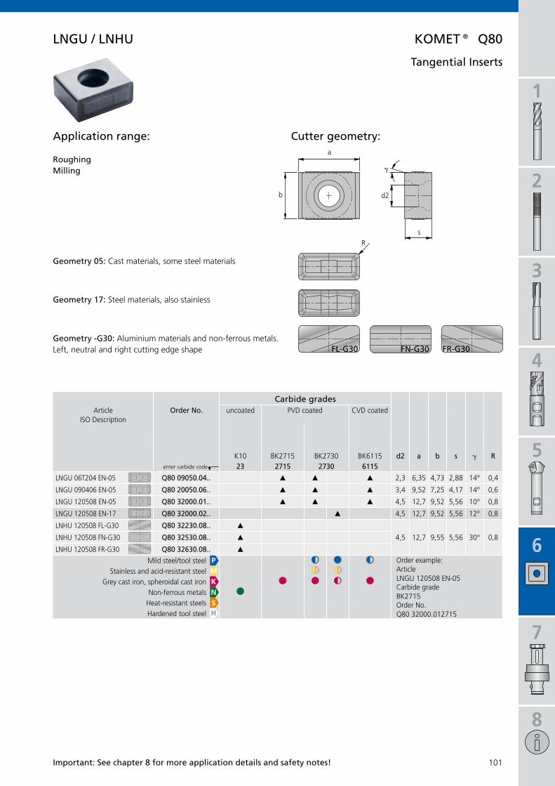
1
2
3
4
5
6
7
8
101
a
s
R
d2b
K10 BK2715 BK2730 BK6115 d2 a b s g R
H___ 23 2715 2730 6115
LNGU 06T204 EN-05 Q80 09050.04.. 2,3 6,35 4,73 2,88 14° 0,4
LNGU 090406 EN-05 Q80 20050.06.. 3,4 9,52 7,25 4,17 14° 0,6
LNGU 120508 EN-05 Q80 32000.01.. 4,5 12,7 9,52 5,56 10° 0,8
LNGU 120508 EN-17 Q80 32000.02.. 4,5 12,7 9,52 5,56 12° 0,8
LNHU 120508 FL-G30 Q80 32230.08.. 4,5 12,7 9,55 5,56 30° 0,8LNHU 120508 FN-G30 Q80 32530.08..
LNHU 120508 FR-G30 Q80 32630.08.. PMKNSH
$ § $
LNGU 120508 EN-05
BK2715
Q80 32000.012715
$ $§ § $ §
§
LnGU / LnHU KOMet® Q80
fL-G30 fn-G30 fR-G30
g
important: see chapter 8 for more application details and safety notes!
Carbide gradesArticle Order no. uncoated PVD coated CVD coated
ISO Description
enter carbide code
Mild steel/tool steel Order example:Article
Carbide grade
Order No.
Stainless and acid-resistant steelGrey cast iron, spheroidal cast iron
Non-ferrous metalsHeat-resistant steelsHardened tool steel
Cutter geometry:Application range:
RoughingMilling
Geometry 05: Cast materials, some steel materials
Geometry 17: Steel materials, also stainless
tangential inserts
Geometry -G30: Aluminium materials and non-ferrous metals. Left, neutral and right cutting edge shape

1
2
3
4
5
6
102
W n M G 0 8 0 4 0 8 f L – 0 1a b c d e f g h i j
a
R
s 90°
L 90°
A 85°
t 60°
C 80° / 100°
e 75°
D 55°
V 35°
W 80°
b
n 0°
B 5°
C 7°
O
P 11°
e 20°
f
t0 1,20 mm
01 1,59 mm
t1 1,80 mm
02 2,38 mm
t2 2,97 mm
03 3,18 mm
t3 3,97 mm
04 4,76 mm
05 5,30 mm
06 6,35 mm
07 7,94 mm
g
00 0,0 mm
01 0,1 mm
02 0,2 mm
03 0,3 mm
04 0,4 mm
05 0,5 mm
06 0,6 mm
08 0,8 mm
12 1,2 mm
16 1,6 mm
20 2,0 mm
24 2,4 mm
ZZ
h
f
e
t
s
i
R
L
n
j
-01
-05
-11
-13
-14
-15
-21
-32
-33
c
s
m
m
d1
d1 s
m s dA ±0,005 ±0,025 ±0,025e ±0,025 ±0,025 ±0,025G ±0,025 ±0,13 ±0,025H ±0,013 ±0,025 ±0,013K ±0,013 ±0,025 ±0,05...±0,15M ±0,08...±0,181) ±0,13 ±0,05...±0,131)
U ±0,13...±0,381) ±0,13 ±0,08...±0,251)
x d1
6,35 ±0,08 ±0,13 d±0,05 ±0,08
9,52 ±0,08 ±0,13 d±0,05 ±0,08
12,70 ±0,13 ±0,20 ±0,08 ±0,13
15,87 ±0,15 ±0,27 ±0,10 ±0,18
19,05 ±0,15 ±0,27 ±0,10 ±0,18
25,40 ±0,18 ±0,38 ±0,13 ±0,25
d
A
M
G
R
W
B
t
H
P
U
X
e
d1mm A C D L R S T V W3,97 06 024,80 04 035,56 05 05 096,35 10 06 07 06 11 11 047,94 08 07 13 138,00 12 08 08 14 059,52 09 11 12 09 16 1610,00 10 0610,90 1612,00 12 0812,70 12 15 12 22 2215,00 1015,88 15 2716,00 1617,60 1219,05 19 19 33 1320,00 2025,00 2525,40 25
isO Codes for inserts
Form
Code
Thickness s
Code
Corner radius RCode
Cutting edge designCode
sharp
rounded
chamfered (negative)
chamfered + rounded
Cutting direction of insertCode
R.H.
L.H.
R.H. and L.H.
Tolerance
Code
Tolerance in mmat m at m at d1 at d1
IC Class M Class U Class M Class U
Type
Code
no chipformer, with hole
chipformer on one side, with hole
chipformer both sides, with hole
chipformer on one side, no hole
no chipformer, countersunk hole 40-60°
no chipformer, countersunk hole 70-90°
chipformer on one side, countersunk hole 40-60°chipformer on one side, countersunk hole 70-90°
neg/pos. one or two sides, with hole
chipformer both sides, with countersunk hole
special design, drawing required
Cutting edge length lCode
at code
Face cutting edge
Chipfomer
Code
medium
Cast iron
Aluminium
finishing
semi-finishing
Clearance angle
Code
according to manufac-turer specification(with KOMET 8°)

1
2
3
4
5
6
7
8
103
Q 2 1 4 4 0 0 0 . 0 1 2 7 3 0Q 8 0 3 2 0 0 0 . 0 1 6 1 1 5
a b c d e f g
c
d1
d1
d1
13 5,56 mm
18 6,35 mm
24 8,0 mm
32 9,52 mm
38 11,1 mm
44 12,7 mm
53 15,88 mm
e
1 ... 9
a
g
03 P25M
04 P40
22 K20
2715 BK2715
2730 BK2730
6115 BK6115
...
b
09
12
15
21
36
80
d
00 ... 99
f
01 ... 99
Inscribed circle d1
Code
Modification code
Code
Main group for standard insertsCode
Material grade
Code
numerical coding for inserts Q..
Secondary group number insert geometry
Code ISO basic forms
S... square 90°
T... triangular 60°
C... rhomboid 80°
E... rhomboid 75°
A... rhomboid form
L... square 90°
Serial number
Code
Serial number
Code

1
2
3
4
5
6
7
104
KOMet®
Benefits for you:
Maximum tool change accuracy
Perfect static rigidity
High radial rigidity
short tool change times
ideal dimensions
Low weight
With our comprehension programme of tool adaptors we have the right answer for every requirement.
Adaptors – Perfecting the connection
Adaptors with connections specified by manufacturers available on request.

1
2
3
4
5
6
7
8
105
106 – 107
108 – 109
110 – 111114
112 – 113115
116
DIN69871AD/B
HSK-AISO
12164-1
5µm
DIN 1835-BWeldon
DIN 1835-EWhistle Notch
symbols
Machine adaptorConnection on machine side p.ex.taper shank DIN 69871 AD/B;HSK-A ISO 12164-1
Vibration dampeningp.ex.torsion dampingbending vibration
pre-balancedQ6,3
8.000 min–1
Balancing noteBalance as despatched adjustable
p.ex.radiallyaxially
CoolantCoolant supplyp.ex. central
Concentricityp.ex. 5µm
System K
KomLoc® HsK clamping system p.ex. system K
Lightweighttool holderConnection on tool side p.ex.Whistle NotchWeldonABS®
tool rotatingstationary
KOMet® Adaptors Page
taper shank Din 69871 AD/B
Milling cutter arbor FA
steilkegelaufnahme Jis B 6339 (MAs 403 Bt)
Milling cutter arbor FA
HsK-A Adaptor isO 12164-1
Milling cutter arbor FACombination milling cutter arbor FAK
ABs® Adaptor
Milling cutter arbor FA / FAMCombination milling cutter arbor FAK
Cylindrical adaptor
for screw-on milling cutter

1
2
3
4
5
6
7
106
KOMet® Din 69871 AD/B
�������� ��������
�������� ��������
L1L2
x d
1
x d
2
1
2
3
L1L2
x d
1 =
40
x d
2
12
3
4
L1L2
x d
1 =
60
x d
2
124
x d3
x d3
...fA40
...fA60
taper shank with milling cutter arbor fA
note: With coolant supply through spindle, use pull stud with through hole. To close off central coolant hole, use pull stud without through hole.
Taper shank in form B complete with conversion kit (for form AD). Please order pull stud separately (page 117).
tool holder ...FA..
tool holder ...FA40
tool holder ...FA60
balancing note (chapter 8)
internalcoolant supply
rotating tool rotating tool
balancedG6,3
8.000 min–1

1
2
3
4
5
6
7
8
107
sK fA
DIN 912 DIN 6367
sK X d1 X d2 X d3 L1 L2
A51 14100SK40-FA16-35
40 16 38 – 35 17 1,0n12 20340
8×8×1455011 03008
M3×855062 00008
M8–
A51 14110SK40-FA22-35
40 22 48 – 35 19 1,0n12 2035010×10×17
55011 04008M4×8
55062 00010M10
–
A51 14120SK40-FA27-40
40 27 50 – 40 21 1,1n12 2036012×14×20
55011 04012M4×12
55062 00012M12
–
A51 14130SK40-FA32-50
40 32 78 – 50 24 1,3n12 2037014×14×22
55011 05012M5×12
55062 00016M16
–
A51 14140SK40-FA40-50*
40 40 88 66,7 50 27 1,6n12 2038015,9×16×21
55011 06016M6×16
55062 00020M20
55011 12040M12×40
A51 14210SK50-FA22-44
50 22 48 – 44 19 3,0n12 2035010×10×17
55011 04008M4×8
55062 00010M10
–
A51 14220SK50-FA27-44
50 27 50 – 44 21 3,2n12 2036012×14×20
55011 04012M4×12
55062 00012M12
–
A51 14230SK50-FA32-40
50 32 78 – 40 24 4,0n12 2037014×14×22
55011 05012M5×12
55062 00016M16
–
A51 14240SK50-FA40-50*
50 40 88 66,7 50 27 4,2n12 2038015,9×16×21
55011 06016M6×16
55062 00020M20
55011 12040M12×40
A51 14250SK50-FA60-70*
50 60 129 101,6 70 40 4,8n12 2039025,4×25×31
55011 12025M12×25
–55011 16050
M16×50
sK fA..-160
DIN 912 DIN 6367
sK X d1 X d2 X d3 L1 L2
A51 14300SK40-FA16-160
40 16 38 – 160 17 2,1n12 20340
8×8×1455011 03008
M3×855062 00008
M8–
A51 14310SK40-FA22-160
40 22 48 – 160 19 2,7n12 2035010×10×17
55011 04008M4×8
55062 00010M10
–
A51 14320SK40-FA27-160
40 27 58 – 160 21 3,7n12 2036012×14×20
55011 04012M4×12
55062 00012M12
–
A51 14330SK40-FA32-160
40 32 78 – 160 24 5,8n12 2037014×14×22
55011 05012M5×12
55062 00016M16
–
A51 14340SK40-FA40-160*
40 40 88 66,7 160 27 6,6n12 2038015,9×16×21
55011 06016M6×16
55062 00020M20
55011 12040M12×40
A51 14410SK50-FA22-160
50 22 48 – 160 19 4,2n12 2035010×10×17
55011 04008M4×8
55062 00010M10
–
A51 14420SK50-FA27-160
50 27 50 – 160 21 5,3n12 2036012×14×20
55011 04012M4×12
55062 00012M12
–
A51 14430SK50-FA32-160
50 32 78 – 160 24 7,2n12 2037014×14×22
55011 05012M5×12
55062 00016M16
–
A51 14440SK50-FA40-160*
50 40 88 66,7 160 27 8,8n12 2038015,9×16×21
55011 06016M6×16
55062 00020M20
55011 12040M12×40
A51 14450SK50-FA60-160*
50 60 129 101,6 160 40n12 2039025,4×25×31
55011 12025M12×25
–55011 16050
M16×50
KOMet® Din 69871 AD/B
DIN 6368Key (page 119) on request.
taper shank with milling cutter arbor fA
Screws 4 for cutter heads
with internal bore location
Key block 1
Cylindricalscrew 2
Cutter clamping screw 3
Bolthole circle
Order no. Order no. Order no. Order no. Order no.Article Article Article Article Article
Screws 4 for cutter heads
with internal bore location
Key block 1
Cylindricalscrew 2
Cutter clamping screw 3
Bolthole circle
Order no. Order no. Order no. Order no. Order no.Article Article Article Article Article
supply includes ...fA..: Milling cutter arbor with cutter clamping screw 3, key block 1 and cylindrical screw 2.supply includes ...fA40: Milling cutter arbor with cutter clamping screw 3, key block 1 and cylindrical screw 2.supply includes ...fA60: Milling cutter arbor with key block 1 and cylindrical screw 2.Please order screws 4 for mounting the cutter heads separately.
* fA40 and 60 with 4 additional screw-in threads for cutter heads with tool clamping to Din 2079.

1
2
3
4
5
6
7
108
KOMet® Jis B 6339 (MAs 403 Bt)
�������� ��������
�������� ��������
L1L2
x d
1
x d
2
1
2
3
L1L2
x d
1 =
40
x d
2
12
3
4
L1L2
x d
1 =
60
x d
2
124
x d3
x d3
...fA40
...fA60
taper shank with milling cutter arbor fA
note: With coolant supply through spindle, use pull stud with through hole. To close off central coolant hole, use pull stud without through hole.
Taper shank in form B complete with conversion kit (for form AD). Please order pull stud separately (page 117).
tool holder ...FA..
tool holder ...FA40
tool holder ...FA60
balancing note (chapter 8)
internalcoolant supply
rotating tool rotating tool
balancedG6,3
8.000 min–1

1
2
3
4
5
6
7
8
109
Bt fA
DIN 912 DIN 6367
Bt X d1 X d2 X d3 L1 L2
A51 15000BT30-FA16-40
30 16 38 – 40 17 0,7n12 20340
8×8×1455011 03008
M3×855062 00008
M8–
A51 15010BT30-FA22-40
30 22 48 – 40 19 0,9n12 2035010×10×17
55011 04008M4×8
55062 00010M10
–
A51 15020BT30-FA27-40
30 27 58 – 40 21 1,0n12 2036012×14×20
55011 04012M4×12
55062 00012M12
–
A51 15030BT30-FA32-50
30 32 78 – 50 24 1,8n12 2037014×14×22
55011 05012M5×12
55062 00016M16
–
A51 15100BT40-FA16-40
40 16 38 – 40 17 1,1n12 20340
8×8×1455011 03008
M3×855062 00008
M8–
A51 15110BT40-FA22-40
40 22 48 – 40 19 1,1n12 2035010×10×17
55011 04008M4×8
55062 00010M10
–
A51 15120BT40-FA27-40
40 27 58 – 40 21 1,2n12 2036012×14×20
55011 04012M4×12
55062 00012M12
–
A51 15130BT40-FA32-50
40 32 78 – 50 24 1,4n12 2037014×14×22
55011 05012M5×12
55062 00016M16
–
A51 15140BT40-FA40-50*
40 40 88 66,7 50 27 1,7n12 2038015,9×16×21
55011 06016M6×16
55062 00020M20
55011 12040M12×40
A51 15210BT50-FA22-63
50 22 48 – 63 19 3,5n12 2035010×10×17
55011 04008M4×8
55062 00010M10
–
A51 15220BT50-FA27-63
50 27 58 – 63 21 3,7n12 2036012×14×20
55011 04012M4×12
55062 00012M12
–
A51 15230BT50-FA32-60
50 32 78 – 60 24 3,6n12 2037014×14×22
55011 05012M5×12
55062 00016M16
–
A51 15240BT50-FA40-60*
50 40 88 66,7 60 27 3,7n12 2038015,9×16×21
55011 06016M6×16
55062 00020M20
55011 12040M12×40
A51 15250BT50-FA60-80*
50 60 129 101,6 80 40 8,5n12 2039025,4×25×31
55011 12025M12×25
–55011 16050
M16×50
Bt fA..-160
DIN 912 DIN 6367
Bt X d1 X d2 X d3 L1 L2
A51 15300BT40-FA16-160
40 16 38 – 160 17 2,2n12 20340
8×8×1455011 03008
M3×855062 00008
M8–
A51 15310BT40-FA22-160
40 22 48 – 160 19 3,0n12 2035010×10×17
55011 04008M4×8
55062 00010M10
–
A51 15320BT40-FA27-160
40 27 58 – 160 21 3,8n12 2036012×14×20
55011 04012M4×12
55062 00012M12
–
A51 15330BT40-FA32-160
40 32 78 – 160 24 4,6n12 2037014×14×22
55011 05012M5×12
55062 00016M16
–
A51 15340BT40-FA40-160*
40 40 88 66,7 160 27 6,9n12 2038015,9×16×21
55011 06016M6×16
55062 00020M20
55011 12040M12×40
A51 15410BT50-FA22-160
50 22 48 – 160 19 4,3n12 2035010×10×17
55011 04008M4×8
55062 00010M10
–
A51 15420BT50-FA27-160
50 27 58 – 160 21 6,0n12 2036012×14×20
55011 04012M4×12
55062 00012M12
–
A51 15430BT50-FA32-160
50 32 78 – 160 24 8,0n12 2037014×14×22
55011 05012M5×12
55062 00016M16
–
A51 15440BT50-FA40-160*
50 40 88 66,7 160 27 9,0n12 2038015,9×16×21
55011 06016M6×16
55062 00020M20
55011 12040M12×40
A51 15450BT50-FA60-160*
50 60 129 101,6 160 40n12 2039025,4×25×31
55011 12025M12×25
–55011 16050
M16×50
DIN 6368
KOMet® Jis B 6339 (MAs 403 Bt)
supply includes ...fA..: Milling cutter arbor with cutter clamping screw 3, key block 1 and cylindrical screw 2.supply includes ...fA40: Milling cutter arbor with cutter clamping screw 3, key block 1 and cylindrical screw 2.supply includes ...fA60: Milling cutter arbor with key block 1 and cylindrical screw 2.Please order screws 4 for mounting the cutter heads separately.
Key (page 119) on request.
taper shank with milling cutter arbor fA
Screws 4 for cutter heads
with internal bore location
Key block 1
Cylindricalscrew 2
Cutter clamping screw 3
Bolthole circle
Order no. Order no. Order no. Order no. Order no.Article Article Article Article Article
Screws 4 for cutter heads
with internal bore location
Key block 1
Cylindricalscrew 2
Cutter clamping screw 3
Bolthole circle
Order no. Order no. Order no. Order no. Order no.Article Article Article Article Article
* fA40 and 60 with 4 additional screw-in threads for cutter heads with tool clamping to Din 2079.

1
2
3
4
5
6
7
110
KOMet® isO 12164-1
�������� ��������
�������� ��������
L1L2
HSK
-Ax
d
x d
1
x d
2
1
2
3
L1L2
HSK
-Ax
d
x d
1 =
40
x d
2
12
3
4
L1L2
HSK
-Ax
d
x d
1 =
60
x d
2
124
x d3
x d3
...fA40 / fA50
...fA60
HsK-A Milling cutter arbor fA
tool holder ...FA..
tool holder ...FA40 / FA50
tool holder ...FA60
balancing note (chapter 8)
internalcoolant supply
rotating tool rotating tool
balancedG2,5
15.000 min–1

1
2
3
4
5
6
7
8
111
HsK-A fA
DIN 912 DIN 6367HsK-AX d X d1 X d2 X d3 L1 L2
A06 33902HSK-A63-FA16-50
63 16 38 – 50 17 1,1n12 20340
8×8×1455011 03008
M3×855062 00008
M8–
A06 33912HSK-A63-FA22-50
63 22 48 – 50 19 1,1n12 2035010×10×17
55011 04008M4×8
55062 00010M10
–
A06 33922HSK-A63-FA27-60
63 27 58 – 60 21 1,3n12 2036012×14×20
55011 04012M4×12
55062 00012M12
–
A06 33932HSK-A63-FA32-60
63 32 78 – 60 24 1,4n12 2037014×14×22
55011 05012M5×12
55062 00016M16
–
A06 33942HSK-A63-FA40-60*
63 40 88 66,7 60 27 1,9n12 2038015,9×16×21
55011 06016M6×16
55062 00020M20
55011 12040M12×40
A06 53902HSK-A100-FA16-50
100 16 38 – 50 17 2,3n12 20340
8×8×1455011 03008
M3×855062 00008
M8–
A06 53912HSK-A100-FA22-50
100 22 48 – 50 19 2,5n12 2035010×10×17
55011 04008M4×8
55062 00010M10
–
A06 53922HSK-A100-FA27-50
100 27 58 – 50 21 2,7n12 2036012×14×20
55011 04012M4×12
55062 00012M12
–
A06 53932HSK-A100-FA32-50
100 32 78 – 50 24 2,8n12 2037014×14×22
55011 05012M5×12
55062 00016M16
–
A06 53942HSK-A100-FA40-60*
100 40 88 66,7 60 27 3,8n12 2038015,9×16×21
55011 06016M6×16
55062 00020M20
55011 12040M12×40
A06 53951HSK-A100-FA50-70*
100 50 95 101,6 70 30n12 2040018×18×27
55011 08020M8×20
55062 00024M24
55011 16050M16×50
A06 53961HSK-A100-FA60-70*
100 60 129 101,6 70 40 6,0n12 2039025,4×25×31
55011 12025M12×25
–55011 16050
M16×50
KOMet® isO 12164-1
DIN 6368
HsK-A Milling cutter arbor fA
Screws 4 for cutter heads
with internal bore location
Key block 1
Cylindricalscrew 2
Cutter clamping screw 3
Bolthole circle
Order no. Order no. Order no. Order no. Order no.Article Article Article Article Article
supply includes ...fA..: Milling cutter arbor with cutter clamping screw 3, key block 1 and cylindrical screw 2.
supply includes ...fA40/fA50: Milling cutter arbor with cutter clamping screw 3, key block 1 and cylindrical screw 2.
supply includes ...fA60: Milling cutter arbor with key block 1 and cylindrical screw 2.
Please order screws 4 for mounting the cutter heads separately. Please order coolant supply connection separately (page 119).
Key (page 119) on request.
* fA40, 50 and 60 with 4 additional screw-in threads for cutter heads with tool clamping to Din 2079.
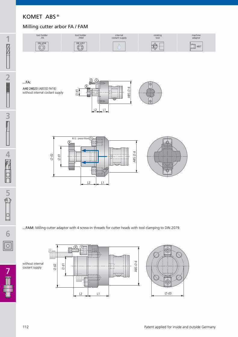
1
2
3
4
5
6
7
112
L2 L1
ABS
x d
x d
1
x d
2
KOMet ABs®
�������� ��������
L1L2
ABS
x d
x d
1
x d
2
L2 L1
ABS
x d
x d
1
x d3
12
13
412
3A40 24023 (ABS50 FA16)
...fA:
Milling cutter arbor fA / fAM
without internal coolant supply
N12.. press-fitted
tool holder ..FA
tool holder ..FAM
internalcoolant supply
rotating tool
machine adaptor
...fAM: Milling cutter adaptor with 4 screw-in threads for cutter heads with tool clamping to DIN 2079.
without internal coolant supply
Patent applied for inside and outside Germany

1
2
3
4
5
6
7
8
113
KOMet ABs®
ABs® fAM
DIN 912ABsX d X d1 X d2 X d3 L1 L2
A40 16062ABS 80-FAM40
80 40 88 66,7 43 30 2,6056341 00001
A4055011 06016
M6×1655011 12040
M12×40
A40 17062ABS100-FAM40
100 40 88 66,7 38 30 3,5056341 00001
A4055011 06016
M6×1655011 12040
M12×40
A40 17072ABS100-FAM60
100 60 130 101,6 56 40 6,5056341 00003
A5055011 12025
M12×2555011 16050
M16×50
ABs® fA
DIN 912 DIN 6367ABsX d X d1 X d2 L1 L2
A40 24023ABS50 FA16
50 16 – 20 17 0,48 A40 24020.1255011 03010
M3×1055062 00008
M8
A40 24034ABS50 FA22
50 22 50 20 19 0,51 n12 20120 –55062 00010
M10
A40 24043ABS50 FA27
50 27 50 20 21 0,57 n12 20140 –55062 00012
M12
A40 24053ABS50 FA32
50 32 63 20 24 0,80 n12 20170 –55062 00016
M16
A40 25032ABS63 FA22
63 22 63 22 19 0,84 n12 20120 –55062 00010
M10
A40 25042ABS63 FA27
63 27 63 22 21 0,90 n12 20140 –55062 00012
M12
A40 25052ABS63 FA32
63 32 63 22 24 0,99 n12 20170 –55062 00016
M16
A40 25062ABS63 FA40
63 40 80 22 27 1,41 n12 20200 –55062 00020
M20
A40 26042ABS80 FA27
80 27 80 25 21 1,59 n12 20140 –55062 00012
M12
A40 26052ABS80 FA32
80 32 80 25 24 1,68 n12 20170 –55062 00016
M16
A40 26062ABS80 FA40
80 40 80 25 27 1,85 n12 20200 –55062 00020
M20
A40 27052ABS100 FA32
100 32 100 25 24 2,10 n12 20170 –55062 00016
M16
A40 27062ABS100 FA40
100 40 100 25 27 2,34 n12 20200 –55062 00020
M20
DIN 6368
Milling cutter arbor fA / fAM
supply includes: Milling cutter adaptor ..FAM with key block 1 and cylindrical screw 2.Please order screws 4 for mounting the cutter heads separately.
Screws 4 for cutter heads
with internal bore location
Key block 1
Cylindricalscrew 2
Bolthole circle
Order no. Order no. Order no. Order no.Article Article Article Article
Drive key 1Key block
Cylindricalscrew 2
Cutter clamping screw 3
Order no. Order no. Order no. Order no.Article Article Article
Key (page 119) on request.
supply includes: Milling cutter adaptor ..FA with drive key/key block 1/cylindrical screw 2 and cutter clamping screw 3.

1
2
3
4
5
6
7
114
KOMet® isO 12164-1
�������� DIN69882-2
HsK-A fAK
DIN 6367HsK-AX d X d1 X d2 L L1 L2
A06 23751HSK-A50-FAK16
50 16 32 50 17 27 0,6255237 00016
16×1051305 04020
A4×4×2055062 00008
M8
A06 23761HSK-A50-FAK22
50 22 40 50 19 31 0,6055237 00022
22×1251305 06025
A6×6×2555062 00010
M10
A06 23771HSK-A50-FAK27
50 27 48 65 21 33 1,0555237 00027
27×1251305 07025
A7×7×2555062 00012
M12
A06 23781HSK-A50-FAK32
50 32 58 65 24 38 1,2555237 00032
32×1451305 08028
A8×7×2855062 00016
M16
A06 33750HSK-A63-FAK16
63 16 32 60 17 27 0,9655237 00016
16×1051305 04020
A4×4×2055062 00008
M8
A06 33760HSK-A63-FAK22
63 22 40 60 19 31 1,1055237 00022
22×1251305 06025
A6×6×2555062 00010
M10
A06 33770HSK-A63-FAK27
63 27 48 60 21 33 1,2255237 00027
27×1251305 07025
A7×7×2555062 00012
M12
A06 33780HSK-A63-FAK32
63 32 58 60 24 38 1,4555237 00032
32×1451305 08028
A8×7×2855062 00016
M16
A06 33790HSK-A63-FAK40
63 40 70 70 27 41 2,1055237 00040
40×1451305 10032
A10×8×3255062 00020
M20
A06 53750HSK-A100-FAK16
100 16 32 60 17 27 2,2055237 00016
16×1051305 04020
A4×4×2055062 00008
M8
A06 53760HSK-A100-FAK22
100 22 40 60 19 31 2,4855237 00022
22×1251305 06025
A6×6×2555062 00010
M10
A06 53770HSK-A100-FAK27
100 27 48 60 21 33 2,5555237 00027
27×1251305 07025
A7×7×2555062 00012
M12
A06 53780HSK-A100-FAK32
100 32 58 60 24 38 2,8055237 00032
32×1451305 08028
A8×7×2855062 00016
M16
A06 53790HSK-A100-FAK40
100 40 70 70 27 41 3,5555237 00040
40×1451305 10032
A10×8×3255062 00020
M20
A06 53800HSK-A100-FAK50
100 50 90 80 30 46 5,0055237 00050
50×1651305 12036
A12×8×3655062 00024
M24
L1 L
L2
HSK
-Ax
d
x d
1
x d
2
1
2
3
tool holder location balancing note (chap. 8)
rotating tool machine adaptor
pre-balancedQ6,3
15.000 min–1
HsK-A Combination milling cutter arbor
K for milling cutters with longitudinal or cross slots
Driving ring 1DIN 6366 Part 1
Feather key 2DIN 6885 Part 1
Cutter clamping screw 3
Order no. Order no.Article
Order no.Article
Order no.ArticleArticle
supply includes: Milling cutter adaptor with driving ring 1, feather key 2 and cutter clamping screw 2. Please order coolant supply connection and key separately (page 119).

1
2
3
4
5
6
7
8
115
KOMet ABs®
��������
ABs® fAK
DIN 6367ABsX d X d1 X d2 L L1 L2 L3
A40 04022ABS50 FAK16
50 16 32 22 27 17 39 0,4655237 00016
16×1051305 04020
A4×4×2055062 00008
M8
A40 04032ABS50 FAK22
50 22 40 22 31 19 43 0,5955237 00022
22×1251305 06025
A6×6×2555062 00010
M10
A40 05021ABS63 FAK16
63 16 32 26 27 17 42 1,055237 00016
16×1051305 04020
A4×4×2055062 00008
M8
A40 05031ABS63 FAK22
63 22 40 26 31 19 46 1,1555237 00022
22×1251305 06025
A6×6×2555062 00010
M10
A40 05041ABS63 FAK27
63 27 48 26 33 21 48 1,2555237 00027
27×1251305 07025
A7×7×2555062 00012
M12
A40 06031ABS80 FAK22
80 22 40 33 31 19 51 1,855237 00022
22×1251305 06025
A6×6×2555062 00010
M10
A40 06041ABS80 FAK27
80 27 48 33 33 21 53 1,955237 00027
27×1251305 07025
A7×7×2555062 00012
M12
A40 06051ABS80 FAK32
80 32 58 33 38 24 58 2,355237 00032
32×1451305 08028
A8×7×2855062 00016
M16
A40 06061ABS80 FAK40
80 40 70 33 41 27 61 2,7555237 00040
40×1451305 10032
A10×8×3255062 00020
M20
L1 L
L2
L3
ABS
x d
x d
1
x d
2
DIN 6368
1
23
Patent applied for inside and outside Germany
Combination milling cutter arbor
tool holder rotating tool
machine adaptor
for milling cutters with longitudinal or cross slots K
Driving ring 1DIN 6366 Part 1
Feather key 2DIN 6885 Part 1
Cutter clamping screw 3
Order no. Order no.Article
Order no.Article
Order no.ArticleArticle
supply includes: Milling cutter adaptor with driving ring 1, feather key 2 and cutter clamping screw 2.
Key (page 119) on request.

1
2
3
4
5
6
7
116
JeL®
L1
L
Mx d
1 x d
2
x d
3
L2
M X d1 X d2 X d3 L L1 L2
58797012000065* M5 9,5 11,5 12 65 20 7,8 0,054
58798012000085 M5 9,5 11,8 12 85 40 9 0,147
58798012000105 M5 9,5 11,8 12 105 60 9 0,166
58798012000125 M5 9,5 11,8 12 125 80 9 0,197
58797016000088* M8 13,8 15,8 16 88 40 7,8 0,122
58798016000108 M8 14,2 15,8 16 108 60 9 0,333
58798016000128 M8 14,2 15,8 16 128 80 9 0,402
58798016000148 M8 14,2 15,8 16 148 100 9 0,451
58798016000168 M8 14,2 15,8 16 168 120 9 0,522
58798016000198 M8 14,2 15,8 16 198 150 9 0,678
58797020000095* M10 18,0 19,8 20 95 45 7,8 0,208
58798020000110 M10 18,5 19,8 20 110 60 9 0,552
58798020000130 M10 18,5 19,8 20 130 80 9 0,654
58798020000150 M10 18,5 19,8 20 150 100 9 0,754
58798020000170 M10 18,5 19,8 20 170 120 9 0,850
58798020000190 M10 18,5 19,8 20 190 140 9 0,958
58797025000106* M12 21,0 24,8 25 106 50 7,8 0,347
58798025000131 M12 23,0 24,8 25 131 75 9 1,022
58798025000156 M12 23,0 24,8 25 156 100 9 1,225
58798025000181 M12 23,0 24,8 25 181 125 9 1,417
58798025000206 M12 23,0 24,8 25 206 150 9 1,620
58798025000231 M12 23,0 24,8 25 231 175 9 1,822
58797032000110* M16 29,0 31,9 32 110 50 7,8 0,619
58798032000160 M16 29,0 31,9 32 160 100 16 2,612
58798032000210 M16 29,0 31,9 32 210 150 16 3,310
58798032000260 M16 29,0 31,9 32 260 200 16 4,174
58798032000310 M16 29,0 31,9 32 310 250 16 4,955
58798036000160 M16 31,5 34,8 36 160 100 9 2,406
58798036000310 M16 31,5 34,8 36 310 250 9
K
Variant: heavy metal, *steel
Cylindrical shank
Order no.
tool holder internalcoolant supply
rotating tool
machine adaptor
Thread
Adaptor for screw-on milling cutter
cylindrical shank for shrink fit chuck

1
2
3
4
5
6
7
8
117
L
G
isO 7388 B
isO 7388/2 B
Din 69872 B
Din 69872 A
isO 7388/2 B
X d1 L G
40 55391 51640 22,5 16,40 M16
45 55391 52045 30,0 20,95 M20
50 55391 52450 37,0 25,55 M24
isO 7388 B
X d1 L G
40 55392 51640 22,5 16,40 M16
45 55392 52045 30,0 20,95 M20
50 55392 52450 37,0 25,55 M24
Din 69872 A
X d1 L G
40 55391 01240 23 26 M16
45 55391 01645 30 30 M20
50 55391 02050 36 34 M24
Din 69872 B
X d1 L G
40 55392 01240 23 26 M16
45 55392 01645 30 30 M20
50 55392 02050 36 34 M24
x d
1
L
G
x d
1
L
G
x d
1L
G
x d
1
KOMet®
note: With coolant supply through spindle, use pull stud with through hole. To close off central coolant hole, use pull stud without through hole.
sealed, for coolant through collar
with through hole
sealed, for coolant through collar
with through hole
isOsize Order no.
isOsize Order no.
isOsize Order no.
isOsize Order no.
Pull studs

1
2
3
4
5
6
7
118
L
HSK
x d
L1
KOMet® HsK-A
HsKX d L L1
HSK-C 40 A06 13470 40 30 10
HSK-C 50 A06 23470 50 37,5 12,5
HSK-C 63 A06 33470 63 44,5 12,5
HSK-C 80 A06 43470 80 56 16
HSK-C100 A06 53470 100 66 16
32 51391 01032
40 51391 01040
50 51391 01050
63 51391 01063
80 51391 01080
100 51391 01100
Periphery
For sealing HSK units against dirt or other contamination.
HsK-A/C Plugs
HsKArticle Order no. X d L L1
Wiper for cleaning taper and face on machine spindle.
Wiper for taper and face
forHSKsize Order no.

1
2
3
4
5
6
7
8
119
L
x d
1
x d
2
KOMet® HsK-A
HsK-AX d1 X d2 L
32 18021 01032 51391 00032 M10×1,0 6 26 5×1,2 2× 52914 00512
40 18021 01040 51391 00040 M12×1,0 8 29,1 7,5×1,5 2× 52914 00751
50 18021 01050 51391 00050 M16×1,0 10 32,7 9×2 2× 52914 00920
63 18021 01063 51391 00063 M18×1,0 12 36,2 10×2,510×2
1×1×
52914 0102552914 01020
80 18021 01080 51391 00080 M20×1,5 14 39,7 13×2 2× 52914 01320
100 18021 01100 51391 00100 M24×1,5 16 43,6 14×3 2× 52914 01430
16 18701 80016
22 18701 80022
27 18701 80027
32 18701 80032
40 18701 80040
50 18701 80050
DIN 6368
note re. supply: the coolant supply connection for the tool adaptors must be ordered separately.Only use the keys listed for assembly. This will prevent coolant flowing back into the machine spindle/clamping system. A specific coolant hose for the machine can also be fitted on all HSK adaptors.
note: The coolant supply unit should be fitted in the tool with the key, to ensure a seal is produced. A coolant supply unit specifically for the machine can also be fitted, if required, using the thread in the tool.
O rings
Coolant supply unit
Key
Mounting of the coolant supply unit
supply coolant supply unit includes: Coolant tube, locking collar and two O rings.
Accessories HsK-A
Key Coolant supply unitO ring
face side and over tube
size Order no. Order no. Article Order no.
Size Order no.
Keyon request

inhaltiDeen-fABRiK + 254Die fabrik der ideen 254informationen 255Leistungsberechnung 255Anwendungstechnische Hinweise 255internationale Werkstoffklassifizierung 255Lieferungs- und Zahlungsbedingungen 255fax-Bestellformular 255nummerischer index 255KOMet GROUP weltweit 255KOMet® 256Leistungsberechnung 256Vollbohren 257KOMet® 257Leistungsberechnung 257KOMet® 258Leistungsberechnung 258Antriebsleistung kW 258Vorschubkraft f
f 258Drehmoment Md 259KOMet® 259Leistungsberechnung 259KOMet® 260Anwendungs- und sicherheitstechnische Hinweise 260Anwendungs- und sicherheitstechnische Hinweise 261KOMet® 261internationale Werkstoffklassifizierung (nach VDi 3323 standard) 262internationale Werkstoffklassifizierung (nach VDi 3323 standard) 263Allgemeine Lieferungs- und Zahlungsbedingungen · KOMet GROUP GmbH 264fax an KOMet seRViCe® Partner Kontakt Seite 252 265Bestellung KomPass – tOOL life 265nummerischer index 266nummerischer index 267nummerischer index 268nummerischer index 269nummerischer index 270nummerischer index 271nummerischer index 272nummerischer index 273nummerischer index 274nummerischer index 275notizen 276KOMet GROUP Vertretungen weltweit 278europa 278international 279
1
2
3
4
5
6
7
8
120120
iDeen-fABRiK +
While the metal swarf flies down below, ideas are exchanged above. By this, we aim to demonstrate that the work here is always associated with new ideas and creative ambition.
With the iDeen-fABRiK and the comprehensive seminar programme for customers and employee qualification, we aim to offer you a measurable and permanent competitive advantage in your markets.
Ask for our no-obligation specialist seminar brochure.
the ideas factory
the iDeen-fABRiK reflects the evolution of theKOMet GROUP from a tool manufacturer into a creative expert for solutions covering all aspects of boring, reaming, thread milling and mechatronic tools.
the central objective is to offer our customers and employees scope for creative working and learning.
On a total area of 2,500 m², we have created a modern, multi-storey factory environment. the iDeen-fABRiKwas deliberately not constructed as a separate,detached training building, but integrated directly above a manufacturing business.
1
2
3
4
5
6
7
8
121
122 – 123
124 – 129
130 – 131
132
133
134 – 135
136
138 – 139
the KOMet GROUP is the worldwide technology leader for innovative tool concepts and complete solutions for drilling machining.
Our customers know us as a manufacturer of premium tools, and know the ideas behind our solutions. the further creativity is still unused, and remains to be discovered. We have set ourselves the objective of exploiting the added value thus created for the benefit of our customers.
We call this tOOLs+iDeAs. A new and different way of being able to offer our customers long-term, sustainable advantages through a plus in support and services.
Our iDeen-fABRiK in Besigheim is the first step in this direction.
informations Page
special solutions for your milling operations
KOMet seRViCe®
A network of local partners that provide professional tool refurbishment, trade tools and manufacture customized solid carbide special tools
KOMet® BRinKHAUs
ToolScope – Next generation process monitoring
screwdriver
Usage and safety notes
numerical index
Order formulae
KOMet GROUP international agencies

1
2
3
4
5
6
7
8
122
Developing customer-specific solutions has always been a showcase discipline at KOMET®. Due to requirements relating to design, tolerance and other quality considerations, machining tasks can often not be accomplished using standard tools. Special process evaluations and tool developments are then required.
special solutions for your milling operations –Greater range of functions, lower machining costs
KOMet® – expertise in special solutions
special side and face milling cutters for machiningthe bearing seat webs in a crankcase
Application example: Material: GSJ 40Cutting data: Cutting speed vc = 100 m/min Feed f = 0,12 mm
Application examples
Benefits for you:
Optimised application design
idle times are significantly reduced
KOMet® experts provide individual and professional advice
Combining several machining operations
Highest efficiency and productivity

1
2
3
4
5
6
7
8
123
KOMet® – expertise in special solutions
Application example: Material: GSJ 50Cutting data: Cutting speed vc = 140 m/min Feed f = 0,1 mm
Application example: Material: GJL 300Cutting data: Cutting speed vc = 130 m/min Feed f = 0,1 mm
special milling cutters for machining the sealing grooves in a pump housing
special milling cutters for machining brake calliper lugs
Application examples
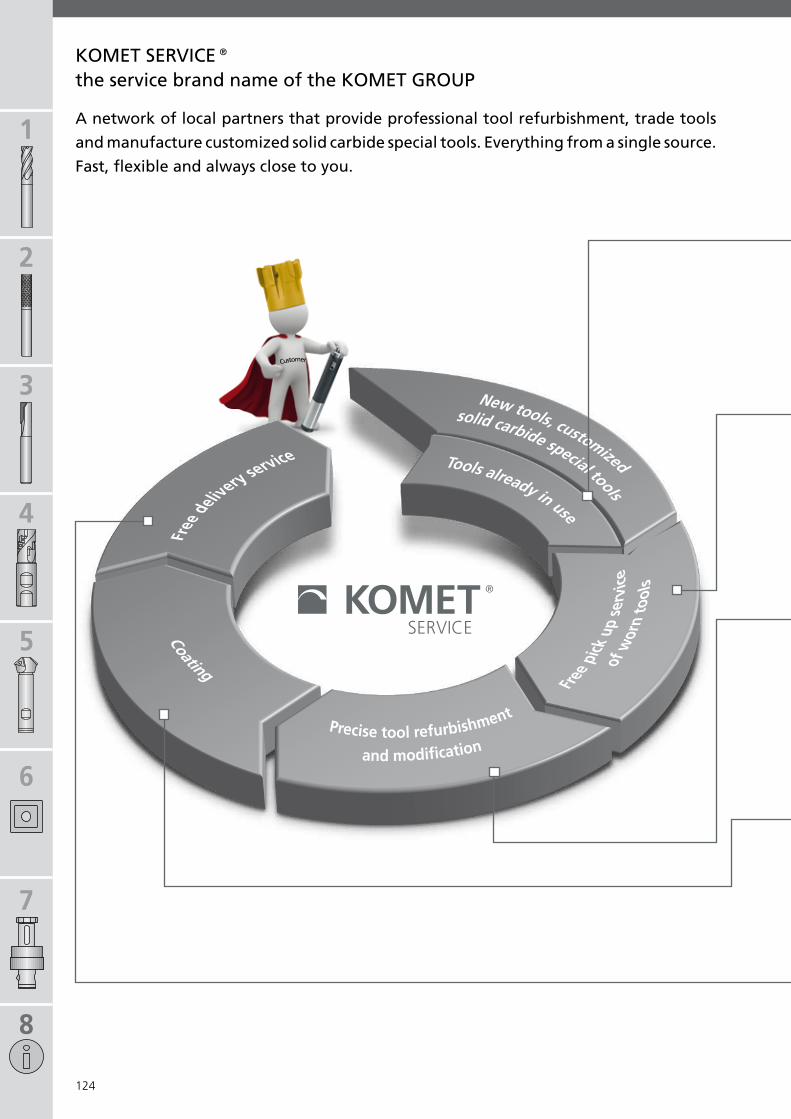
1
2
3
4
5
6
7
8
124
KOMet seRViCe®
Customer
A network of local partners that provide professional tool refurbishment, trade tools
and manufacture customized solid carbide special tools. everything from a single source.
fast, flexible and always close to you.
the service brand name of the KOMet GROUP
Precise tool refurbishment
and modif cation
Coating
Tools already in use
New tools, customized
Free
delivery service
solid carbide special tools
Free p
ick u
p se
rvic
eof
wor
n to
ols

125
1
2
3
4
5
6
7
8
125
from stock or individually manufacturedGet your solid carbide TOOLlife tools directly from your KOMET SERVICE® partner or have your own customized solid carbide special tools manufactured.Your KOMET SERVICE® partner will happily refurbish these tools along with all tools from other brands.
One call does it allGet on a regular pick-up schedule or arrange a one-time pick-up of your tools needing refurbishment by your KOMET SERVICE® partner. It’s fast and it’s free.
tools refurbished to original quality Our refurbishing experts fairly assess the current state of your tools (irrespective of the manufacturer) in order to recommend refurbishment or replacement.KOMET GROUP tools are refurbished according to strict criteria to restore the original geometry or original tipping. By request you receive a measurement report. Our partners will also professionally modify tools for you, quickly and flexibly.
Just-in-time delivery Your KOMET SERVICE® partner will return your KOMET GROUP tools refurbished to their original quality within 5 or 10 days (without or with coating) – safely stored in the KOMET SERVICE® TOOL life box.
Coating – fully customized KOMET GROUP tools are of course given the original coatings once more. We customize our service to your needs, even with other standard coatings, all within a few days.

a Görans Slipservice AB Ångpannegatan 3SE-417 05 GöteborgTel. +46 31 232060Fax +46 31 [email protected]
b Werkzeugschleiferei Bodo Krause Inh. Tino KrauseUnter den Linden 1D-23948 RolofshagenTel. +49 3881 4822Fax +49 3881 [email protected]
c Werkzeugservice Wulf e.K. Industriestr. 40D-30900 WedemarkTel. +49 5130 37670Fax +49 5130 [email protected]
d Herbert Schaube WerkzeugschleifereiAlt-Blankenburg 25D-13129 BerlinTel. +49 30 47471037Fax +49 30 [email protected]
e D. Hermes GmbH & Co. KGOtto-Hahn-Str. 8D-58739 WickedeTel. +49 2377 92810Fax +49 2377 [email protected]
f Kanne Werkzeugtechnik GmbHBorsigstr. 29D-37154 NortheimTel. +49 5551 988060Fax +49 5551 [email protected]
g CNC-Werkzeugschleiferei & Werkzeughandel SteikertAm Bahnhof 1D-06567 GöllingenTel. +49 34671 79652Fax +49 34671 [email protected]
h Vogtland Schleiftechnik GmbH & Co. KG Moorstr. 20D-08527 PlauenTel. +49 3741 27600Fax +49 3741 [email protected]
i Zero systems, s.r.o.Pod Tratí 493/16CZ-32200 PlzeňTel. +420 377927171Fax +420 [email protected]
j Andre Woitschach GmbHMax-Berk-Straße 2D-69226 NusslochTel. +49 6224 5701875Fax +49 6224 16 [email protected]
k Schnebelt PräzisionBurdastr. 21D-77746 SchutterwaldTel. +49 781 960444Fax +49 781 [email protected]
l Werkzeugschleiferei LiebrichObere Brandstr. 10D-70567 StuttgartTel. +49 711 714995Fax +49 711 [email protected]
m Werkzeugschleiferei Schlenker GmbHMögglinger Str. 64D-73560 BöbingenTel. +49 7173 929073Fax +49 7173 [email protected]
n InovaTools Eckerle & Ertel GmbHIm Hüttental 3D-85125 Kinding-HaunstettenTel. +49 8467 84000Fax +49 8467 [email protected]
o Schneidwerkzeuge Schleiftechnik MoserHauptstr. 21D-94556 Schönanger-NeuschönauTel. +49 8558 663Fax +49 8558 [email protected]
p NB WerkzeugtechnikIm Anwandel 12D-72459 AlbstadtTel. +49 7432 2009422Fax +49 7432 [email protected]
q Max Beck GmbHBeizkofer Str. 49D-88512 MengenTel. +49 7572 760310Fax +49 7572 [email protected]
r WEMA GmbHRaiffeisenstraße 9D-85276 PfaffenhofenTel. +49 8441 859160 Fax +49 8441 [email protected]
s Gradauer G.M.B.H.Ternberger Straße 1aA-4596 Steinbach/SteyrTel. +43 7257 7366 Fax +43 7257 7366 [email protected]
t DHB Werkzeugtechnik GmbHGösgerstrasse 15CH-5012 SchönenwerdTel. +41 62 8494192Fax +41 62 [email protected]
21u AFLY, Affûtage Lyonnais S.A.S.200 rue Léon BlumF-69100 VilleurbanneTel. +33 472 148939Fax +33 472 [email protected]
5
4
6
3
4 Ekstrom Carlson5248 27th AvenueRockford, IL 61109, USATel. +1 815 394 1744Fax +1 815 316 [email protected]
5 Countyline Tool, Inc.3303 N. Main StreetEast Peoria, IL 61611, USATel. +1 309 694 2400Fax +1 309 694 [email protected]
6 Tri-State Tool Grinding5311-A Robert AveCincinnati, OH 45248, USATel.: +1 513 347 0100Fax: +1 513 347 [email protected]
1 Castelar Tool & Grinding Inc.7171 Torbram Road, Unit C-2L4T 3W4, Mississauga, Ontario, CATel. +1 9056773090Fax +1 [email protected]
2 TechFab Inc.400 Ave MarienH1B4V6, Montreal-Est, Quebec, CATel.: +1 5146408451Fax: +1 [email protected]
3 Integrity Saw & Tool507 West Rolling Meadows DriveFond du Lac, WI 54937, USATel.: +1 920 923 4474Fax: +1 920 923 [email protected]
1 2
1
2
3
4
5
6
7
8
126
fast, flexible and always close to youfast, flexible and always close to you
KOMet seRViCe® Partner

www.kometservice.com
1
2
3
4
5
6
7
8
127
B
C D
E
F
G
H
KM
N
O
PQ
T
I
J
R S
A
L
U21
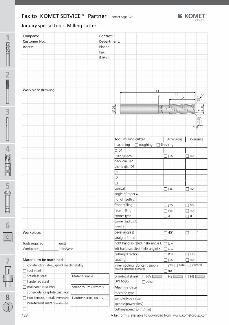
1
2
3
4
5
6
7
8
128
x D
1
x D
2
ax D
3
L2L3
L1
bf
R
x D1
n n
L1
L2
L3
n n
n nn nn A n B
n 45° n ____°
nn l =
n l =
n nn nnn
DIN 6535n HA n HE n HB
n
Company:
Customer no.:
Adress:
Contact:
Department:
Phone:
fax:
e-Mail:
Workpiece drawing:
fax to KOMet seRViCe® Partner Contact page 126
Workpiece:
Tools required ________units
Workpiece ___________units/year
Material to be machined:
n construction steel, good machinability
n tool steel
n stainless steel
n hardened steel
n malleable cast iron
n spheroidal graphite cast iron
n non-ferrous metals (refractory)
n non-ferrous metals (malleable)
n ___________
Hardness (HRc, HB, HV, ...)
Strength Rm (N/mm²)
Material name
inquiry special tools: Milling cutter
Machine data
machine type
spindle type / size
spindle power (kW)
cutting speed vc (m/min)
tool: milling cutter Dimensions Tolerance
machining n roughing n finishing
neck groove yes no
neck dia. D2
shank dia. D3
conical yes no
angle of taper a
no. of teeth z
front milling yes no
face milling yes no
corner type
corner radius R
bevel f
bevel angle b
straight fluted
right hand spiraled, helix angle l
left hand spiraled, helix anglel l
cutting direction R.H. L.H.
coating yes no
inner cooling lubricant supply cooling lubricant discharge
yes: n side n central
no
cylindrical shank
other:
A fax form is available to download from www.kometgroup.com

1
2
3
4
5
6
7
8
129
nn l =
n l =
n nn nnn
DIN 6535n HA n HE n HB
n
Company:
Customer no.:
Adress:
Contact:
Department:
Phone:
fax:
e-Mail:
Workpiece drawing:
fax to KOMet seRViCe® Partner Contact page 126
Workpiece:
Tools required ________units
Workpiece ___________units/year
Material to be machined:
n construction steel, good machinability
n tool steel
n stainless steel
n hardened steel
n malleable cast iron
n spheroidal graphite cast iron
n non-ferrous metals (refractory)
n non-ferrous metals (malleable)
n ___________
Hardness (HRc, HB, HV, ...)
Strength Rm (N/mm²)
Material name
Machine data
machine type
spindle type / size
spindle power (kW)
cutting speed vc (m/min)
tool: form cutter Dimensions Tolerance
shank dia.
overall length
no. of teeth z
straight fluted
right hand spiraled, helix angle l
left hand spiraled, helix anglel l
cutting direction R.H. L.H.
coating yes no
inner cooling lubricant supply cooling lubricant discharge
yes: n side n central
no
cylindrical shank
other:
inquiry special tools: form cutter
A fax form is available to download from www.kometgroup.com

1
2
3
4
5
6
7
8
130
KOMet® BRinKHAUs
toolscope – next generation process monitoring
Growing automation in the machining industry increases the demand for more process and machine tool monitoring, which can help minimize machine down time and reduce scrap rates, thereby improving the delivery times to your customers.
Based on the latest technology of process and machine tool monitoring, the ToolScope System from KOMET® BRINKHAUS relies on a unique, patented method for statistical process monitoring which not only detects breakage but also recognizes considerably smaller process deviations. In addition to the usual procedures of process control, the ToolScope System provides a procedure for monitoring quality while a process is running.
BRinKHAUs toolscope adds considerable value to your production
BRINKHAUS ToolScope has an advantage over other systems not only because it features the latest technology, but also because of its modularity and user-friendliness. It provides for simple and safe application of the system in many different areas, even with small batch runs. Indeed, the built-in dynamic monitoring capabilities alleviate the need for a “learning period” before the system can start monitoring a process.
Monitoring DocumentationVisualisation Optimisation
Benefits for you:
Online visualization of the process (oscilloscope function) to support the set-up procedure, e.g. in order to promptly detect the jamming of chips
Six Sigma Module: statistical process verification and process quality monitoring
Dynamic Monitoring Module: Process monoitoring for small batch runs which alleviates the need for a learning
Adaptive Control (AC) Module: Optimization of the es-sential operating time through process acceleration for tools that are underused, and speed reduction for tools that are overused
Measuring without (additional) sensors: The sensor data is read directly from the CNC via Profibus or TCP/IP
Automatic documentation of the process data as a PDF, PNG or Excel file
Monitoring for tool wear and missing tool
Monitoring of any and all possible sensor signals
Evaluating analogue sensor signals with up to 10 kHz
Monitoring of the vibration behavior of bearings, axles, spindles and tools
Operation via the machine control system HMI or using a touch screen
Chipping
impedes production
Time (s)
Channal 1: Torque / Spindle / Chrion FZ 15S
Torq
ue
Time (s)
Torq
ue
Torque/spindle/machine control systemAverage feed force
Number of processes
feed
fo
rce (
kn
)

1
2
3
4
5
6
7
8
131
KOMet® BRinKHAUs
400×220×110200×140×110410×320×90
technical data
Dimensions (W×D×H) Data – mm (inch) noteIPC version (15.748×8.661×4.331)
DIN Rail Module (7.874×5.512×4.331)
Touch Panel PC version (16.142×12.598×3.543) 15‘‘ Display
interfaces sample rate noteProfibus with synchronous actions approx. 20 - 30 HzProfibus with compile cycle approx. 100 - 500 Hz See belowTCP/IP yesAnalog input channels up to 10 kHz 8 inputs, during monitoring perhaps lower sample
rate
Digital input/output channels 8 input/output channels each
supported control systemsSiemens 840D SL, 840D PL, Heidenhain, Fanuc, Beckhoff from year 2000 and later, other control systems and year of manu-facture available upon request.
Profibus connectionRequirements for compile cycleSample rate approx. 100 Hz
Drive hardware: SIMODRIVE 611D based drive system, digital drive, delivers digital current/torque information
Control hardware: SINUMERIK 840D, • NCU: 572.3 or 573.2 or higher (572.2 only SW4.4), • storage: min. 32 MB, • PROFIBUS interface
Control software: SINUMERIK 840D technology board, version 05.03.06(NCU_05.03.18) or 04.04.11 (NCU_04.04.37) or higher
Requirements for compile cycleSample rate approx. 100 - 500 Hz
in addition to the above mentioned requirements, the following must apply:Control software: SINUMERIK 840D, NC-Software $ 06.03
Visualization on HMi (only siemens)Requirements Windows 95 and later, network card
start monitoring with the BRinKHAUs toolscope systemMonitoring can automatically be started by changing from G0 to G1. Furthermore the processes can automatically be stored in reference to the tool number, workpiece number, program name, etc.
FunctionalityVisualization Each process can easily and continously be visualized (oscilloscope function).Data logging Each process is automatically stored on the hard disk (logbook).Filtering The system offers a variety of filters such as average value, effective value, RMS, variance,
etc. as standard for the filtering of the input signals.
Monitoring tool breakage The basic system contains a self learning algorithm to recognize tool breakage. The tole-rance bands are simply and automatically identified.
Monitoring tool wear The system offers tracing and monitoring of tool wear. By setting warning thresholds, the operator can be forewarned of worn tools.
Six Sigma Strategy (optional)Online statistical process control
With this monitoring algorithm, minimal process deviations such as wear, larger cavities, changes in material can be recognized during consistant serial production processes. This is equivalent to conducting real-time quality control while a process is running.
Adaptive Control (AC) Module (optional)
With adaptive control, the feed is optimized so that the effective power of the tool re-mains as constant as possible. Therefore, the essential operation time can significantly be reduced, e.g. during roughing. Moreover, the feed can be reduced if an effective power limit is exceeded, thus protecting the tool.
Dynamic Monitoring Module (optional)
With this monitoring strategy, the process and the tool can be monitored from as early as lot size 1. Here the system is also fully self-learing.
BRinKHAUs toolscope Basic system including installation / commissioning: Order no. e65 01010Enhanced with: Dynamic Monitoring Module
Order No. E65 21020Adaptive Control (AC) ModuleOrder No. E65 21030

1
2
3
4
5
6
7
8
132
torxPlus®
5IP L05 00800 9IP L05 00840
6IP L05 00810 10IP L05 00850
7IP L05 00820 15IP L05 00860
8IP L05 00830 20IP L05 00870
torquefix®
5IP 0,38 Nm L05 00901 L05 00700
6IP 0,62 Nm L05 00911L05 00710
6IP 1,01 Nm L05 03301
7IP 0,90 Nm L05 00921 L05 00720
8IP 1,28 Nm L05 00931L05 00730
8IP 2,25 Nm L05 03311
9IP 2,50 Nm L05 00941 L05 00740
10IP 2,80 Nm L05 00951 L05 00750
15IP 4,30 Nm L05 00961 L05 00760
20IP 6,25 Nm L05 00971 L05 00770
easytorque
5IP 0,38 Nm L05 00902 L05 00700
6IP 0,62 Nm L05 00912L05 00710
6IP 1,01 Nm L05 00922
8IP 1,28 Nm L05 00932
L05 007308IP 1,8 Nm L05 03320
8IP 2,25 Nm L05 00942
9IP 2,50 Nm L05 00952 L05 00740
10IP 2,80 Nm L05 00962 L05 00750
15IP 4,30 Nm L05 00972 L05 00760
torqueVario®
5IP – 7IP
0,38 - 1,01 Nm L05 00781
L05 00700
L05 00710
L05 00720
9IP – 20IP
2,25 - 6,25 Nm L05 00791
L05 00740
L05 00750
L05 00760
L05 00770
KOMet®
1
2
3
screwdriver
The old Torx keys do fit the new TORX PLUS® shape but we recom-mend only. TORX PLUS® keys be used for tightening screws.
TORX PLUS® is a registered trademark for the Camcar Division of Textron Inc.
To ensure the correct starting torque on screws, the torque key from the TORX PLUS® system has. Complies with the following requirements: EN ISO 6789, BS EN 26789, ASME B107.14M (with certificate).
appropriatereplaceable blade
Size Torque Order no. Order no.
torque wrench torquefix®with fixed preset torqueaccuracy: ± 6% release torque: + 30%
supply includes: Torque wrench without replaceable blade.
supply includes: Torque wrench without replaceable blade.
torque wrench easytorquewith fixed preset torqueaccuracy: ± 10% release torque: unbounded
appropriatereplaceable blade
Size Torque Order no. Order no.
torque wrench torqueVario®adjustable with scale
supply includes: Torque wrench with adjusting key L05 00990, without replaceable blade.
appropriatereplaceable blade
Size Torque Order no. Order no.
Size Order no. Size Order no.
Changing the torque
1 Remove blade
2 Insert adjusting key in variable torque key handle and turn to set the required torque. The appropriate IP size can be read from the graduated scale.
3 Push blade in again

1
2
3
4
5
6
7
8
133
KOMet®
Tool holders or adaptors are only balanced as supplied, i.e. no allowance has been made for items which can alter this, such as boring tools, milling cutters, inserts, etc. When used at high speeds, we recommend precision balancing be carried out when the tool is fitted ready for use.
Balancing note:
Usage and safety notes
If using tungsten carbide-based hard metal products together with cobalt as a binder metal, please read our safety data sheets, which are available for you to download from our website.(http://www.kometgroup.com/navigation-top/download/service/datenblaetter.html)
Hazard warning:
The application details given depend on the environmental and application conditions (e.g. machine, ambient temperature, lubricant/coolant used and machining result required): they are based on the correct application conditions, correct use and compliance with the spindle speed limits given for the tools.

1
2
3
4
5
6
7
8
134
18021 01032 11918021 01040 11918021 01050 11918021 01063 11918021 01080 11918021 01100 119
37140026004000 4737140026005000 4737140026006300 4737140026008000 4737140026010000 4737140026012500 4737140026016000 47
37150026004000 4737150026005000 4737150026006300 4737150026008000 4737150026010000 4737150026012500 4737150026016000 47
37340099001000 4537340099001200 4537340099001600 4537340099002000 4537340099002500 4537341099001000 4637341099001200 4637341099001600 4637341099002000 4637341099002500 4637341099003200 46
38300057000600 5138300072001000 5138300090001600 5138304057000600 5038304063000800 5038304072001000 50
38390000000600 4438390000000800 4438390000001000 4438390000001200 4438391000001600 4438391000002000 4438392057000600 4438392063000800 4438392072001000 4438392083001200 4438393004002000 4438393090001600 44
51391 00032 11951391 00040 11951391 00050 11951391 00063 11951391 00080 11951391 00100 11951391 01032 11851391 01040 11851391 01050 11851391 01063 11851391 01080 11851391 01100 118
52914 00512 11952914 00751 11952914 00920 11952914 01020 11952914 01025 11952914 01320 11952914 01430 119
55391 01240 11755391 01645 11755391 02050 11755391 51640 117
55391 52045 11755391 52450 11755392 01240 11755392 01645 11755392 02050 11755392 51640 11755392 52045 11755392 52450 117
58797012000065 11658797016000088 11658797020000095 11658797025000106 11658797032000110 116
58798012000085 11658798012000105 11658798012000125 11658798016000108 11658798016000128 11658798016000148 11658798016000168 11658798016000198 11658798020000110 11658798020000130 11658798020000150 11658798020000170 11658798020000190 11658798025000131 11658798025000156 11658798025000181 11658798025000206 11658798025000231 11658798032000160 11658798032000210 11658798032000260 11658798032000310 11658798036000160 11658798036000310 116
70900105022000 1070900157020300 1070900157020400 1070900157020500 1070900157020600 1070900163020800 1070900172021000 1070900182021200 1070900182021400 1070900192021600 1070900192021800 10
70901105032000 1070901157030300 1070901157030400 1070901157030500 1070901157030600 1070901163030800 1070901172031000 1070901182031200 1070901182031400 1070901192031600 1070901192031800 10
70902105042000 1070902157040300 1070902157040400 1070902157040500 1070902157040600 1070902163040800 1070902172041000 1070902182041200 1070902182041400 1070902192041600 1070902192041800 10
70903100021000 1170903150020600 1170903160020800 1170903175020600 11
70903175020800 1170903175021000 11
70904100041000 1170904105041200 1170904105042000 1170904150040600 1170904160040800 1170904175040600 1170904175040800 1170904175041000 1170904182041200 1170904182041400 1170904192041600 1170904192041800 11
70905104042000 1570905157040600 1570905163040800 1570905172041000 1570905182041200 1570905182041400 1570905192041600 1570905192041800 15
70906104042000 1270906157040600 1270906163040800 1270906172041000 1270906183041200 1270906183041400 1270906192041600 12
70920557030600 2370920563030800 2370920572041000 2370920582041200 2370921557030600 2370921563030800 2370921572041000 2370921582041200 2370922570040603 2470922570040702 2470922575040605 2470922575040607 2470922575040609 2470922575040808 2470922580040809 24
70933000021000 2570933005022000 2570933057020300 2570933057020400 2570933057020500 2570933057020600 2570933063020800 2570933072021000 2570933075020600 2570933075020800 2570933082021200 2570933092021600 25
70934005032000 2570934057030300 2570934057030400 2570934057030500 2570934057030600 2570934063030800 2570934072031000 2570934082031200 2570934092031600 25
70950400020800 1670950400021000 1670950405021200 1670950405021400 1670950450020500 1670950450020600 1670950460020300 1670950460020800 16
70950460021600 1670950460021800 1670950460022000 1670950475020400 1670950475020500 1670950475020600 1670950475021000 16
70951405041200 1670951405041400 1670951450040500 1670951450040600 1670951460040800 1670951460041600 1670951460041800 1670951460042000 1670951475041000 16
70955105022004 1970955105022005 1970955150020602 1970955150020603 1970955160020802 1970955160020803 1970955175021002 1970955175021003 1970955175021005 1970955182021204 1970955182021205 1970955192021604 1970955192021605 19
70956105042004 1970956105042005 1970956150040602 1970956150040603 1970956160040802 1970956160040803 1970956175041002 1970956175041003 1970956175041005 1970956182041204 1970956182041205 1970956192041604 1970956192041605 19
78910205082000 1378910250040300 1378910250040400 1378910257060600 1378910263060800 1378910272061000 1378910282061200 1378910292081600 1378910292081800 13
78911257060600 1478911263080800 1478911272101000 1478911282121200 1478911292161600 14
78912250020402 2078912250020602 2078912260020802 2078912260020803 2078912260020805 2078912275021002 2078912275021003 2078912275021005 20
78913200040802 2078913200040803 2078913200041003 2078913200041005 2078913275040402 2078913275040602 2078913275040603 20
78914250060601 2178914250060602 2178914260060801 2178914260060802 2178914275061002 2178914275061003 21
78915200020604 2278915200020805 2278915200021006 2278915205021207 22
78931004002000 2678931020002500 2678931057000600 2678931063000800 2678931072001000 2678931083001200 2678931090001600 26
78935000010800 2778935050010400 2778935050010500 2778935050010600 2778935050010800 2778935075010400 2778935075010500 2778935075010600 27
78952405021000 1778952405021200 1778952405021600 1778952450020300 1778952450020400 1778952480020600 1778952480020800 17
78953400020600 1878953400020800 1878953400021000 1878953400021200 1878953460021600 18
78954400040600 1878954400040800 1878954400041000 1878954400041200 1878954460041600 18
78955150020302 1978955150020402 1978955150020403 19
78956150040302 1978956150040402 1978956150040403 19
78980040000400 3678980050000600 3678980063000800 3678980072001000 3678980075000400 3678980075000600 3678980075000800 36
78981040000400 3678981050000600 3678981063000800 3678981072001000 3678981075000400 3678981075000600 3678981075000800 3678981083001200 36
78982050000400 3678982060000600 3678982063000800 3678982072001000 36
Order No. Page
numerical index
Order No. Page Order No. Page Order No. Page Order No. Page

1
2
3
4
5
6
7
8
135
78983050000400 3678983060000800 3678983063000600 3678983072001000 36
78984050000400 3778984060000600 3778984063000800 3778984072001000 3778984075000400 3778984075000600 3778984075000800 37
78985050000400 3778985060000600 3778985063000800 3778985072001000 3778985075000400 3778985075000600 3778985075000800 37
78986050000400 3778986060000600 3778986060000800 3778986072001000 3778986075000400 3778986075000600 3778986075000800 37
78987050000400 3778987060000600 3778987060000800 3778987072001000 3778987075000400 3778987075000600 3778987075000800 37
78988060000400 3878988060000600 3878988063000800 3878988072001000 3878988075000600 3878988075000800 38
78989060000400 3878989060000600 3878989063000800 3878989072001000 3878989075000600 3878989075000800 38
A06 13470 118A06 23470 118A06 23751 114A06 23761 114A06 23771 114A06 23781 114
A06 33470 118A06 33750 114A06 33760 114A06 33770 114A06 33780 114A06 33790 114A06 33902 111A06 33912 111A06 33922 111A06 33932 111A06 33942 111
A06 43470 118
A06 53470 118A06 53750 114A06 53760 114A06 53770 114A06 53780 114A06 53790 114A06 53800 114A06 53902 111
A06 53912 111A06 53922 111A06 53932 111A06 53942 111A06 53951 111A06 53961 111
A40 04022 115A40 04032 115A40 05021 115A40 05031 115A40 05041 115A40 06031 115A40 06041 115A40 06051 115A40 06061 115
A40 16062 113A40 17062 113A40 17072 113
A40 24023 113A40 24034 113A40 24043 113A40 24053 113A40 25032 113A40 25042 113A40 25052 113A40 25062 113A40 26042 113A40 26052 113A40 26062 113A40 27052 113A40 27062 113
A51 14100 107A51 14110 107A51 14120 107A51 14130 107A51 14140 107A51 14210 107A51 14220 107A51 14230 107A51 14240 107A51 14250 107A51 14300 107A51 14310 107A51 14320 107A51 14330 107A51 14340 107A51 14410 107A51 14420 107A51 14430 107A51 14440 107A51 14450 107
A51 15000 109A51 15010 109A51 15020 109A51 15030 109A51 15100 109A51 15110 109A51 15120 109A51 15130 109A51 15140 109A51 15210 109A51 15220 109A51 15230 109A51 15240 109A51 15250 109A51 15300 109A51 15310 109A51 15320 109A51 15330 109A51 15340 109A51 15410 109A51 15420 109A51 15430 109A51 15440 109A51 15450 109
F10 00051 82F10 00061 82F10 00071 82F10 00081 82F10 00091 82F10 00101 82F10 00350 82F10 00370 82F10 00380 82F10 00390 82F10 00400 82
F10 10021 80F10 10031 80F10 10040 80F10 10050 80F10 10060 80F10 11070 80F10 11080 80F10 11090 80F10 11100 80F10 11110 80F10 11120 80F10 11130 80
F51 01040 73F51 01050 73F51 01060 73F51 01080 73F51 01190 58F51 01200 58F51 01210 58F51 01220 58F51 01230 58F51 01240 58F51 01250 58F51 02340 52F51 02350 52F51 02360 52
F51 12040 72F51 12050 72F51 12060 72F51 12080 72F51 12100 72F51 12120 72F51 12180 72F51 14040 61F51 14050 61F51 14060 61F51 14080 61F51 14100 61F51 14120 61F51 14160 61
F51 34110 52F51 34120 52F51 34130 52
F51 40300 70F51 40310 70F51 40320 70F51 40360 70F51 42060 71F51 42080 71
F51 50052 66F51 50062 66F51 50072 66F51 50082 66F51 50102 66F51 50122 66F51 50162 66F51 50181 66F51 50251 66F51 50410 66F51 50420 66F51 50460 66F51 50620 67F51 50660 67
F51 60081 69F51 60101 69F51 60121 69F51 60151 69F51 60191 69F51 60231 69
F51 70050 62F51 70080 62F51 70121 63F51 70140 63F51 70201 63F51 71031 64F51 71101 64
F53 30110 68F53 30191 68
H20 21011 84H20 21021 84H20 21031 84H20 21111 84H20 21511 84H20 21521 84
H20 32121 85H20 32131 85H20 32141 85H20 32151 85H20 32161 85H20 32171 85
H20 42011 85H20 42021 85H20 42041 85H20 42061 85H20 42071 85H20 42101 85H20 42121 85H20 43011 84H20 43021 84H20 43111 84H20 43121 84H20 43141 84
L01 01020 61L01 01030 61L01 01040 61L01 01050 61L01 01060 61L01 01070 61
L05 00700 132L05 00710 132L05 00720 132L05 00730 132L05 00740 132L05 00750 132L05 00760 132L05 00770 132L05 00781 132L05 00791 132L05 00800 132L05 00810 132L05 00820 132L05 00830 132L05 00840 132L05 00850 132L05 00860 132L05 00870 132L05 00901 132L05 00902 132L05 00911 132L05 00912 132L05 00921 132L05 00922 132L05 00931 132L05 00932 132L05 00941 132L05 00942 132
L05 00951 132L05 00952 132L05 00961 132L05 00962 132L05 00971 132L05 00972 132
L05 03301 132L05 03311 132L05 03320 132
Q09 13000.01.. 91Q09 18000.17.. 92Q09 44000.02.. 93Q09 44000.13.. 93Q09 44000.15.. 93Q09 44000.23.. 93
Q12 18000.01.. 94Q12 18000.02.. 94Q12 18000.03.. 94Q12 18000.04.. 94Q12 18000.10.. 96Q12 18000.11.. 95Q12 18000.12.. 95Q12 18000.13.. 95Q12 18000.14.. 95Q12 18000.31.. 96Q12 18000.32.. 96Q12 18000.33.. 96Q12 18000.34.. 96Q12 18000.36.. 97
Q12 32000.05.. 94Q12 32000.06.. 94Q12 32000.07.. 94Q12 32000.08.. 94Q12 32000.09.. 94Q12 32000.15.. 96Q12 32000.16.. 96Q12 32000.17.. 96Q12 32000.18.. 95Q12 32000.19.. 95Q12 32000.20.. 95Q12 32000.38.. 97Q12 32000.41.. 96Q12 32000.42.. 96Q12 32000.43.. 96Q12 32000.52.. 94Q12 32000.53.. 94
Q12 44000.21.. 95Q12 44000.22.. 95Q12 44000.23.. 95Q12 44000.25.. 95Q12 44000.84.. 96Q12 44000.85.. 96Q12 44000.86.. 96Q12 44000.87.. 96
Q15 18000.01.. 98Q15 18000.02.. 98Q15 32000.03.. 98Q15 32000.04.. 98
Q36 18000.01.. 99Q36 24000.02.. 99Q36 24000.04.. 100Q36 24000.05.. 100Q36 24000.06.. 100Q36 38000.07.. 99
Q80 09050.04.. 101Q80 20050.06.. 101Q80 32000.01.. 101Q80 32000.02.. 101Q80 32230.08.. 101Q80 32530.08.. 101Q80 32630.08.. 101
Order No. Page Order No. Page Order No. Page Order No. PageOrder No. Page
numerical index

1
2
3
4
5
6
7
8
136
fax Order +49 7143 373233
KomPass – Milling
Customer No. – please specify Order No. Order date Supplier No.
Company Company
Contact person (surname) Name Contact person (surname) Name
Branch Department/site Branch Department/site
Street Street
Town/city, postcode Town/city, postcode
Tel. Fax Tel. Fax
Date Signature
Order quantity
Order No. Tool name / ItemArticle
Customer material number
Additional information
Delivery address (if different)
This order is subject to the KOMET GROUP GmbH conditions of supply and payment.

tOOLs PLUs iDeAs – a PLUs for our customers and the environment
the company targets
The KOMET GROUP pursues a consistent policy of investments and achieves long-term
and profitable growth via continuous improvement of products and processes as well as
via consistent qualification of employees. This increases the value of the company. The
KOMET GROUP consistently increases its innovation quota via research and development,
offering the market new products every year. The KOMET GROUP is a premium quality
manufacturer and motivates employee qualification and customers in their IDEAS FACTORY.
The training quota of vocational beginners is exemplary for the entire field of business.
the products and services
KOMET GROUP products and services offer the customer incomparable added value.
The KOMET GROUP develops, manufactures and sells the most comprehensive, modular
portfolio on bore machining as full-range suppliers. The KOMET GROUP offers the most
innovative technologies, thereby taking the highest economic viability, best quality and
most attractive designs into account. The KOMET GROUP sees itself not purely as a tool
manufacturer, but rather as suppliers of innovative solutions and ideas for the benefit of the
customer: TOOLS AND IDEAS.
the customer
The KOMET GROUP places value on long-term, binding customer relations, seeing itself as
a partner of the customer in a balance of benefit supplies and benefit harvests.
The KOMET GROUP records customers' demands and then produces the most effective
ideas and tool solutions for their machining tasks. The KOMET GROUP offers the customer
information and collaboration via their worldwide presence in local Service Centres. The
IDEAS FACTORY supports vocation-related training and further qualifications for customers.
the environment / surroundings
The KOMET GROUP feels itself obliged to avoid any wastage, and therefore commits itself
to responsible usage of raw materials and careful utilisation of remaining materials.
The KOMET GROUP management is well aware of its responsibilities towards society, and
creates the foundations for modern working environments and working conditions. The
specifications on ergonomics and work safety are taken into account. Beholden to the
founder, Robert Breuning, the KOMET GROUP supports the site at Besigheim, maintaining
direct contact to schools and social facilities in the region.
With these claims in mind, the KOMet GROUP has introduced a modern, integrated
management system, known as KMs (KOMet Management system), which is certi-
fied in accordance with isO 9001:2008, isO 14001:2009 and the German „Akkredi-
tierungs-und Zulassungsverordnung Arbeitsförderung – AZAV“.
Certification
http://www.kometgroup.com/navigation-top/download/service/zertifikate.html
Certified
M
anagement System

KOMET Scandinavia ABBox 9177SE-200 39 MalmöTel. +46-40-49 28 40Fax +46-40-49 19 [email protected]
KOMET GROUP GmbHZeppelinstraße 374354 BesigheimTel. +49 7143 3730Fax +49 7143 [email protected]
P.Aro OyHallimestarinkatu 9FI-20780 KAARINATel. +358-(0)20 1474500Fax +358-(0)20 [email protected]
KOMET S.à.r.l.46-48 Chemin de la Bruyère69574 Dardilly CEDEXTel. +33(0)4 37 46 09 00Fax +33(0)4 78 35 36 [email protected]
KOMET (UK) Ltd.4 Hamel HouseCalico Business ParkTamworthB77 4BFTel. +44(0)1827.302518Fax +44(0)[email protected]
KOMET (UK) Ltd.4 Hamel HouseCalico Business ParkTamworthB77 4BFTel. +44(0)1827.302518Fax +44(0)[email protected]
KOMET Utensili S.R.L.Via Massimo Gorki n. 1120098 S. Giuliano Mil.Tel. +39-02-9 84 02 81Fax +39-02-9 84 49 [email protected]
NITEH d.o.o.Izidora Krsnjavog 1 B47000 HR-KarlovacTel. +385 47 60 01 41Fax +385 47 60 01 [email protected]
Roco B.V.Willem Barentszweg 165928 LM VenloTel. +31-77-3 23 14 00Fax +31-77-3 23 14 [email protected]
KOMET Scandinavia ABBox 9177SE-200 39 MalmöTel. +46-40-49 28 40Fax +46-40-49 19 [email protected]
KOMET GROUP GmbHZeppelinstraße 3D-74354 BesigheimTel. +43 512 28 35 59 32 Fax +43 512 28 35 59 [email protected]
KOMET-URPOL Sp. z o.o ul. Przyjaźni 47 bPL 47-225 Kędzierzyn-KoźleTel. +48 77 405 31 00Fax +48 77 405 31 [email protected]
KOMET IBERICA TOOLS S.L. Av. Corts Catalanes 9-11Planta baja, local 6B 08173 Sant Cugat del VallesTel. +34-93-583.96.20Fax +34-93-583.96.12
S.C. INMAACRO S.R.L. Avram Iancu 86505600 Săcele-BraşovTel. +40 368 443 500Fax +40 368 443 [email protected]
KOMET GROUP GmbH ul. M.Salimganova 2V420107, Kazan Tel. +7 843 5704345Fax +7 843 [email protected]
KOMET Scandinavia ABBox 9177SE-200 39 MalmöTel. +46-40-49 28 40Fax +46-40-49 19 [email protected]
KOMET GROUP GmbHZeppelinstraße 3D-74354 BesigheimTel. +49 7143 3730Fax +49 7143 [email protected]
KOMET GROUP CZ s.r.o.Na Hůrce 1041/2,160 00 Praha 6Tel. +42(0)2 35 01 00 10Fax +42(0)2 35 31 18 [email protected]
Schmidt HSC d.o.o.Kidriceva 253000 CeljeTel. +386 3 49 00 850Fax +386 3 49 00 [email protected]
KOMET IBERICA TOOLS S.L. Av. Corts Catalanes 9-11Planta baja, local 6B 08173 Sant Cugat del VallesTel. +34-93-583.96.20Fax [email protected]
KOMET GROUP CZ s.r.o.Na Hůrce 1041/2,160 00 Praha 6Tel. +420 235010010Fax +420 [email protected]
KOMET KESICI TAKIMLAR SAN VE TIC LTD STIYenikoy Mahallesi Koybasi cad. Akbas Sokak no 7 Sariyer ISTANBULTel. +90 212 346 01 34 Tel. +90 212 346 01 70Fax +90 212 346 01 [email protected]
POWER TOOLS KFT9019 GYOR, Tavirózsa u. 3/FTel. +36 96 511 011Fax +36 96 511 [email protected]
KOMet GROUP international Agencies
europe
Denmark
Germany
finland
france
Great Britain
ireland
italy
Croatia
netherlands
norway
Austria
Poland
Portugal
Romania
Russia
sweden · Denmark · norway
switzerland
slovack Republic
slovenia
spain
Czech Republic
turkey
Hungary

ZAHRANCO, ENGINEERING TRADE15, Ali Amer Str. · 6th SectorNasr City · Cairo, EgyptTel. +20-2-2 75 43 46Fax +20-2-2 75 41 83Telex 2 10 57 YAZCO UN
VORTEX S.R.L.Pedro Morán 858Lomas del MiradorBuenos AiresTel. +54-(11) 46 53 01 25Fax +54-(11) 44 88 60 [email protected]
Rosler International PTY Ltd.P.O. BOX 696, 12 The NookBayswater, Vic. 3153Tel. +61-3-97 38 08 89Fax +61-3-97 38 08 87
Komet do Brasil Ltda.Rua Brasileira, 43907043-010 Guarulhos - São PauloTel. +55(0)11.2423-5502Fax +55(0)[email protected]
KOMET GROUP OF CHINANo. 5 Schaeffler Road Taicang, Jiangsu Province, PRC 215400Tel. +86 512 53575758Fax +86 512 [email protected]
KOMET Precision Tools India Pvt. Ltd.16J, Attibele Industrial AreaBANGALORE - 562 107Tel. +91-80-2807 8000Fax +91-80-2807 [email protected]
KOMET GROUP Precision Tools (Thailand) Co.,Ltd.1558/61 Soi BaanKlangKrung 11,Bangna-Trad Road. Bangna, Bangkok 10260 Thailand
SHIVEH TOLID Co. LTD.# 270, West Dr. Fatemi Ave.Post Code : 14186TehranTel. +98 21 6 691 7 691Fax +98 21 6 691 7 [email protected]
ARNOLD TRADING Co., Ltd.P.O.B. 201806 Hamachtesh St.Ind. Area, Holon 58810Tel. +9 72-3-5 58 13 13Fax +9 72-3-5 58 13 17
KOMET GROUP KK# 180-00061-22-2 Naka-cho Musashino-shiTokyo Japan Grand Preo Musashino 203Tel. +81(0)422 50 0682Fax +81(0)422 50 [email protected]
KOMET of CANADATooling Solutions ULC250 Harry Walker Parkway NUnit 6B, Newmarket,Ontario, L3Y 7B4Tel. +1 (905) 954-0466Fax +1 (905) [email protected]
KOMET GROUP Precision ToolsKorea Co.,Ltd.#201, Lotte IT Castle-2, 550-1,Gasan-dong,Geumcheon-gu, Seoul, 153-768Tel. +82(0)2.2082.6300Fax +82(0)[email protected]
KOMET GROUP Precision Tools (Thailand) Co.,Ltd.1558/61 Soi BaanKlangKrung 11,Bangna-Trad Road. Bangna, Bangkok 10260 Thailand
KOMET de México S. de R. L. de C.VAcceso 1 Nave 8 No. 116 Fraccionamiento Industrial La Montaña Querétaro, Qro. C.P 76150 MéxicoTel. +52 442 2109020Fax +52 442 [email protected]
Coulson Carbide LimitedDouble J Centre, 24 Gum Road,Henderson Valley, HendersonP.O.Box 21-228, HendersonAuckland Tel. +64-9-8 38 50 61Fax +64-9-8 37 62 86
KOMET GROUP Precision Tools (Thailand) Co.,Ltd.1558/61 Soi BaanKlangKrung 11,Bangna-Trad Road. Bangna, Bangkok 10260 Thailand
MULTITRADE DISTRIBUTORSP.O. Box 3511Kempton Park1620Tel. +27-11-453-8034Fax +27-11-453-9696
Hung Chih Ltd., Co.No. 37, Chung Cheng RoadTainan, Taiwan, R.O.C.Tel. +8 86-6-2 25 22 16Fax +8 86-6-2 20 59 [email protected]
KOMET GROUP Precision Tools (Thailand) Co.,Ltd.1558/61 Soi BaanKlangKrung 11,Bangna-Trad Road. Bangna, Bangkok 10260 Thailand
KOMET of America, Inc.2050 Mitchell Blvd.SchaumburgIL 60193-4544Tel. +1 (8 47) 9 23 / 84 00 +1 (8 47) 9 23 / 84 80Fax +1 (8 00) 8 65 / 66 [email protected]
KOMET GROUP Precision Tools (Thailand) Co.,Ltd.1558/61 Soi BaanKlangKrung 11,Bangna-Trad Road. Bangna, Bangkok 10260 Thailand
Outside europe
egypt
Argentina
Australia
Brazil
China
india
indonesia
iran
israel
Japan
Canada
Korea
Malaysia
Mexico
new Zealand
singapore
south Africa
taiwan
thailand
UsA
Vietnam

www.kometgroup.com
KOMET GROUP GmbH Zeppelinstraße 3 · 74354 BesigheimTel. +49 7143 3730 · Fax +49 7143 373233 · [email protected]
KOMET do Brasil Ltda.Rua Brasileira, 439 · 07043-010 Guarulhos - São PauloTel. +55 11 24235502 · Fax +55 11 24220069 [email protected]
KOMET GROUP OF CHINANo. 5 Schaeffler Road Taicang, Jiangsu Province, PRC 215400Tel. +86 512 53575758 · Fax +86 512 [email protected]
KOMET S.à.r.l.46-48 Chemin de la Bruyère · 69574 Dardilly CEDEXTel. +33(0) 4 37 46 09 00 · Fax +33(0) 4 78 35 36 57 · [email protected]
KOMET (UK) Ltd.4 Hamel House · Calico Business Park · Tamworth · B77 4BFTel. +44(0)1827.302518 · Fax +44(0)1827.300486 · [email protected]
KOMET Precision Tools India Pvt. Ltd. 16J, Attibele Industrial Area · BANGALORE - 562 107Tel. +91 80 2807 8000 · Fax +91 80 2807 [email protected]
KOMET Utensili S.R.L.Via Massimo Gorki n. 11 · 20098 S. Giuliano Mil.Tel. +39 02 98 40 28 1 · Fax +39 02 98 44 96 2 · [email protected]
KOMET GROUP KK# 180-0006 · 1-22-2 Naka-cho Musashino-shi Tokyo Japan · Grand Preo Musashino 203 Tel. +81(0)422 50 0682 · Fax +81(0)422 50 [email protected]
KOMET de México S. de R. L. de C.VAcceso 1 Nave 8 No. 116 · Fraccionamiento Industrial La MontañaQuerétaro, Qro. C.P 76150 MéxicoTel. +52 442 2109020 · Fax +52 442 [email protected]
KOMET GROUP GmbHZeppelinstraße 3 · D-74354 BesigheimTel. +43 512 28355932 · Fax +43 512 28355999 · [email protected]
KOMET-URPOL Sp. z o.o ul. Przyjaźni 47 b · PL 47-225 Kędzierzyn-KoźleTel. +48 77 405 31 00 · Fax +48 77 405 31 10 · [email protected]
KOMET GROUP GmbHZeppelinstraße 3 · D-74354 BesigheimTel. +49 7143 3730 · Fax +49 7143 373233 · [email protected]
KOMET of America, Inc.2050 Mitchell Blvd. · Schaumburg · IL 60193-4544Tel. +1 (8 47) 9 23 / 84 00 · +1 (8 47) 9 23 / 84 80Fax +1 (8 00) 8 65 / 66 [email protected]
KOMET Scandinavia ABBox 9177 · SE-200 39 MalmöTel. +46 40 49 28 40 · Fax +46 40 49 19 95 · [email protected]
KOMET IBERICA TOOLS S.L.Av. Corts Catalanes 9-11 · Planta baja, local 6B · 08173 Sant Cugat Del VallesTel. +34 93 5839620 · Fax +34 93 5839612 · [email protected]
KOMET GROUP GmbH ul. M.Salimganova 2V · 420107, Kazan Tel. +7 843 5704345 · Fax +7 843 2917543 · [email protected]
KOMET of CANADA Tooling Solutions ULC250 Harry Walker Parkway N · Unit 6B, Newmarket, Ontario, L3Y 7B4Tel. +1 905 9540466 · Fax +1 905 [email protected]
KOMET GROUP Precision Tools Korea Co., Ltd.#201, Lotte IT Castle-2, 550-1, Gasan-dong, Geumcheon-gu, Seoul, 153-768Tel. +82(0)2.2082-6300 · Fax +82(0)[email protected]
KOMET GROUP CZ s.r.o.Na Hůrce 1041/2, 160 00 Praha 6Tel. +420 235010010 · Fax +420 235311890 · [email protected]
KOMET KESICI TAKIMLAR SAN VE TIC LTD STIYenikoy Mahallesi Koybasi cad. · Akbas Sokak no 7 Sariyer ISTANBULTel. +90 212 346 01 34 · Tel. +90 212 346 01 70 · Fax +90 212 346 01 64 · [email protected]
KOMET GROUP Precision Tools (Thailand) Co.,Ltd. 1558/61 Soi BaanKlangKrung 11, Bangna-Trad Road. Bangna, Bangkok 10260 Thailand
KOMET GROUP GmbH · Werk StuttgartRuppmannstraße 32 · 70565 Stuttgart-VaihingenTel. +49 711 788910 · Fax +49 711 7889111
399 01 004 04-2T-02/14 Printed in Germany www.wachter.de · © 2014 KOMET GROUP GmbH · We reserve the right to make modifications.
Ko
mPa
ss –
Mill
ing
KomPass – Milling
GerMany
France
china
Great Britain
india
italy
JaPan
Mexico
austria
Poland
switzerland
usa
sweden · denMarK · norway
sPain
russia
Brazil
canada
Korea
czech rePuBlic
turKey
southeast asia