Embed Size (px)
Citation preview
Processos de
Separação com
Membranas
UNIVERSIDADE FEDERAL DO RIO DE JANEIRO
EQB737 – TECNOLOGIAS VERDES PARA BIOPRODUTOS
Prof Bernardo DiasProf Bernardo Dias
Introdução
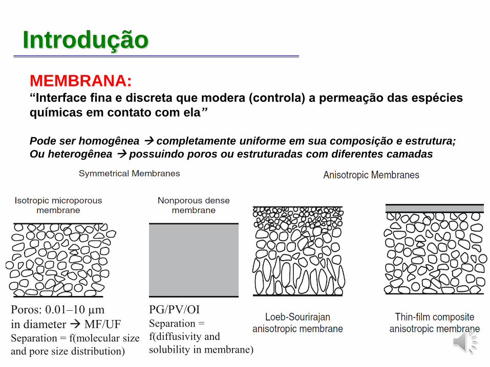
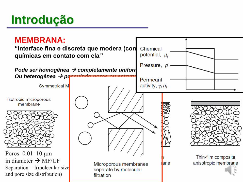
MEMBRANA: “Interface fina e discreta que modera (controla) a permeação das espécies
químicas em contato com ela”
Pode ser homogênea → completamente uniforme em sua composição e estrutura;
Ou heterogênea → possuindo poros ou estruturadas com diferentes camadas
Poros: 0.01–10 µm
in diameter→MF/UFSeparation = f(molecular size
and pore size distribution)
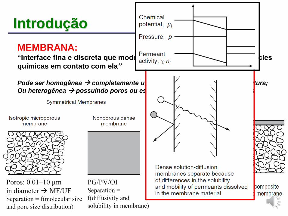
PG/PV/OISeparation =
f(diffusivity and
solubility in membrane)
Introdução
MEMBRANA: “Interface fina e discreta que modera (controla) a permeação das espécies
químicas em contato com ela”
Pode ser homogênea → completamente uniforme em sua composição e estrutura;
Ou heterogênea → possuindo poros ou estruturadas com diferentes camadas
Poros: 0.01–10 µm
in diameter→MF/UFSeparation = f(molecular size
and pore size distribution)
PG/PV/OISeparation =
f(diffusivity and
solubility in membrane)
Introdução
PROCESSOS DE SEPARAÇÃO COM MEMBRANAS
energéticamente favorável
operação em condições brandas (p e T)
modular
acoplamento simples com processos convencionais
Limitações:
seletividade (massa molar, difusão e troca iônica) e fluxos reduzidos
incrustações
condições de operação brandas (p, T)
resistência química
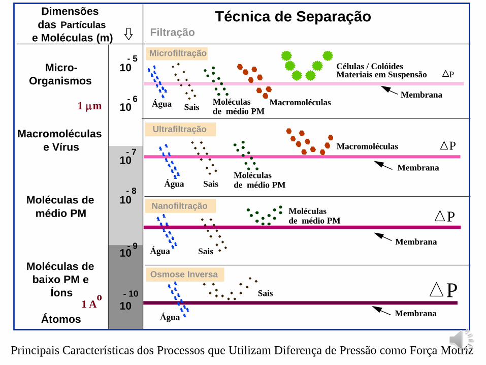
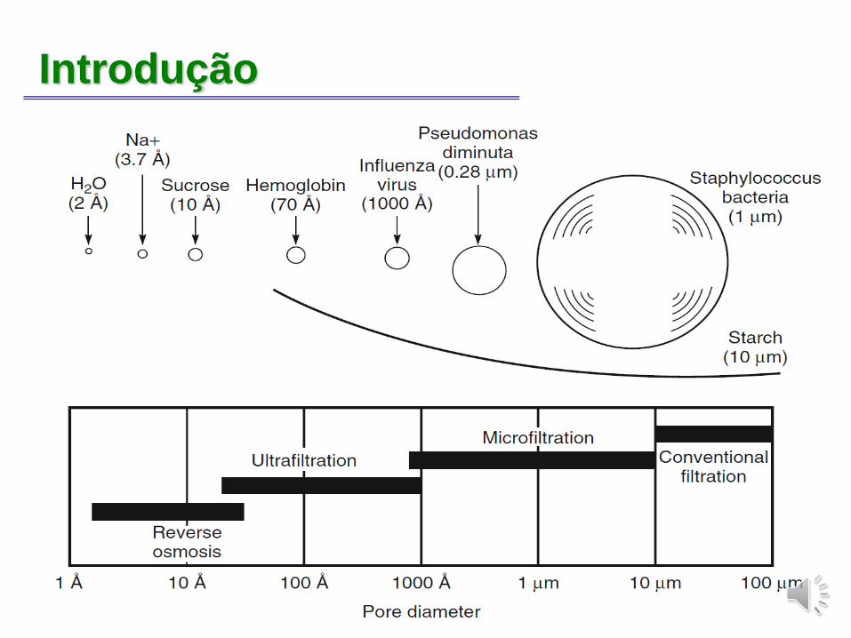
Micro-
Organismos
Macromoléculas
e Vírus
Moléculas de
médio PM
Moléculas de
baixo PM e
Íons
Átomos
- 5
- 6
- 9
- 10
10
10
10
10
10
10
Técnica de SeparaçãoFiltração
1 m
Dimensões
das Partículas
e Moléculas (m)
1 Ao
- 7
- 8
Microfiltração
Água Sais Macromoléculas
Células / ColóidesMateriais em Suspensão
Membrana
P
Moléculasde médio PM
Ultrafiltração
Água Sais
Macromoléculas
Membrana
P
Água Sais
Nanofiltração
Membrana
P
Osmose Inversa
Água
Sais
Membrana
P
Moléculasde médio PM
Moléculasde médio PM
Principais Características dos Processos que Utilizam Diferença de Pressão como Força Motriz
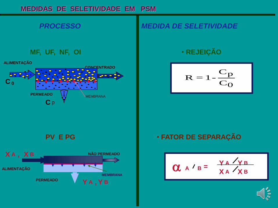
R = 1-C
C
p
0
• REJEIÇÃO
ALIMENTAÇÃO
C 0
CONCENTRADO
PERMEADOMEMBRANA
C p
MF, UF, NF, OI
PROCESSO MEDIDA DE SELETIVIDADE
MEDIDAS DE SELETIVIDADE EM PSM
• FATOR DE SEPARAÇÃO
Y BY A
AX BX A B =
PV E PG
ALIMENTAÇÃO
NÃO PERMEADO
PERMEADO
MEMBRANA
AY BY,
X A X B,
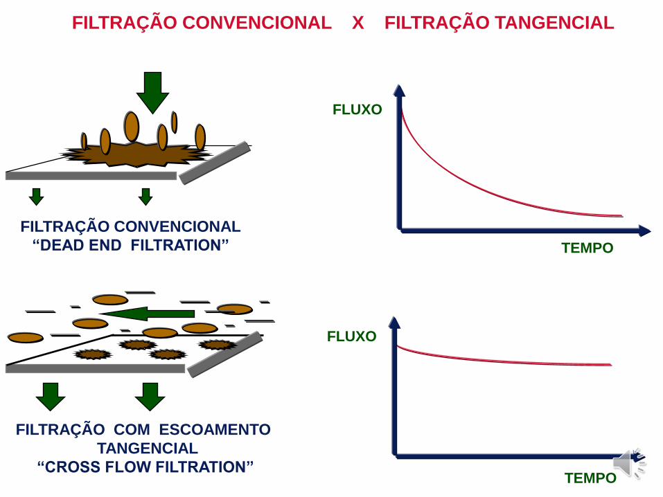
FILTRAÇÃO CONVENCIONAL
“DEAD END FILTRATION”
FILTRAÇÃO COM ESCOAMENTO
TANGENCIAL
“CROSS FLOW FILTRATION”
FLUXO
TEMPO
TEMPO
FLUXO
FILTRAÇÃO CONVENCIONAL X FILTRAÇÃO TANGENCIAL
Parâmetros
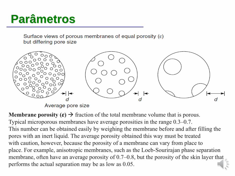
Membrane porosity (ε) → fraction of the total membrane volume that is porous.
Typical microporous membranes have average porosities in the range 0.3–0.7.
This number can be obtained easily by weighing the membrane before and after filling the
pores with an inert liquid. The average porosity obtained this way must be treated
with caution, however, because the porosity of a membrane can vary from place to
place. For example, anisotropic membranes, such as the Loeb-Sourirajan phase separation
membrane, often have an average porosity of 0.7–0.8, but the porosity of the skin layer that
performs the actual separation may be as low as 0.05.
Parâmetros
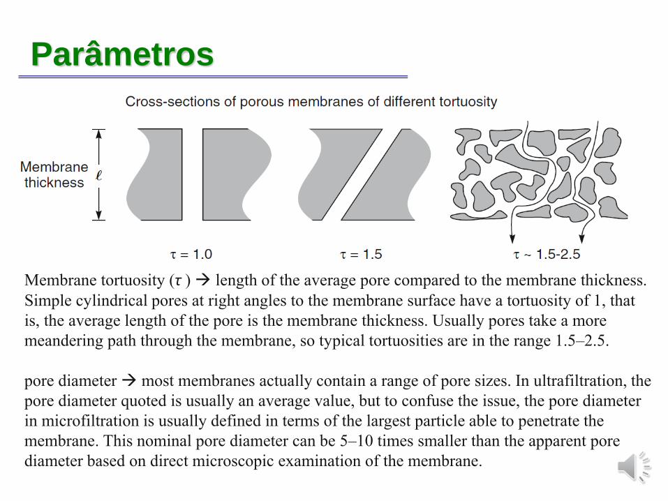
Membrane tortuosity (τ ) → length of the average pore compared to the membrane thickness.
Simple cylindrical pores at right angles to the membrane surface have a tortuosity of 1, that
is, the average length of the pore is the membrane thickness. Usually pores take a more
meandering path through the membrane, so typical tortuosities are in the range 1.5–2.5.
pore diameter → most membranes actually contain a range of pore sizes. In ultrafiltration, the
pore diameter quoted is usually an average value, but to confuse the issue, the pore diameter
in microfiltration is usually defined in terms of the largest particle able to penetrate the
membrane. This nominal pore diameter can be 5–10 times smaller than the apparent pore
diameter based on direct microscopic examination of the membrane.
Parâmetros
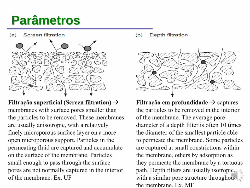
Filtração superficial (Screen filtration) →
membranes with surface pores smaller than
the particles to be removed. These membranes
are usually anisotropic, with a relatively
finely microporous surface layer on a more
open microporous support. Particles in the
permeating fluid are captured and accumulate
on the surface of the membrane. Particles
small enough to pass through the surface
pores are not normally captured in the interior
of the membrane. Ex. UF
Filtração em profundidade → captures
the particles to be removed in the interior
of the membrane. The average pore
diameter of a depth filter is often 10 times
the diameter of the smallest particle able
to permeate the membrane. Some particles
are captured at small constrictions within
the membrane, others by adsorption as
they permeate the membrane by a tortuous
path. Depth filters are usually isotropic,
with a similar pore structure throughout
the membrane. Ex. MF
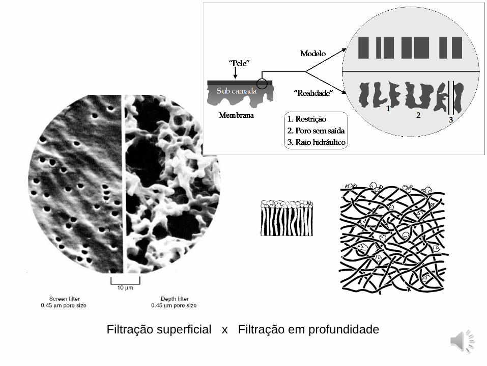
Filtração superficial x Filtração em profundidade
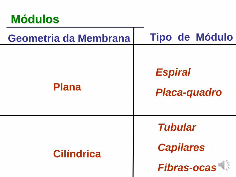
Módulos
Plana
Cilíndrica
Tubular
Capilares
Fibras-ocas
Espiral
Placa-quadro
Geometria da Membrana Tipo de Módulo
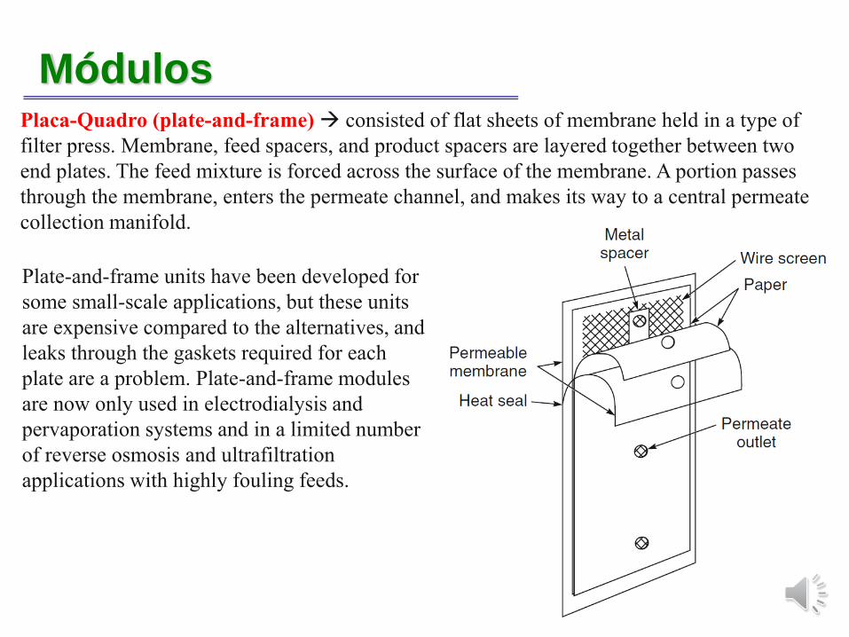
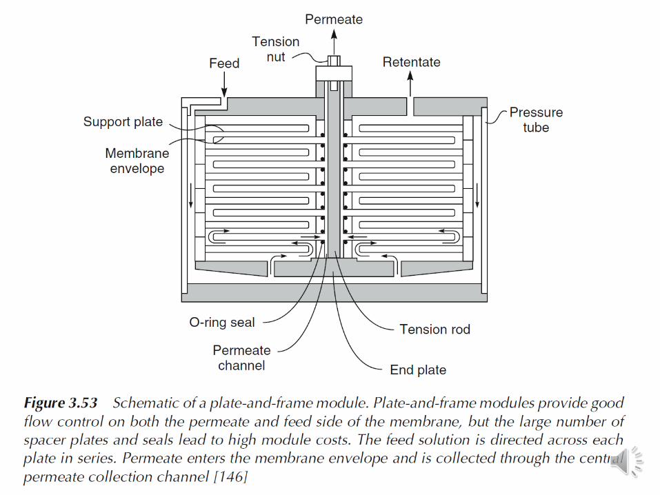
MódulosPlaca-Quadro (plate-and-frame) → consisted of flat sheets of membrane held in a type of
filter press. Membrane, feed spacers, and product spacers are layered together between two
end plates. The feed mixture is forced across the surface of the membrane. A portion passes
through the membrane, enters the permeate channel, and makes its way to a central permeate
collection manifold.
Plate-and-frame units have been developed for
some small-scale applications, but these units
are expensive compared to the alternatives, and
leaks through the gaskets required for each
plate are a problem. Plate-and-frame modules
are now only used in electrodialysis and
pervaporation systems and in a limited number
of reverse osmosis and ultrafiltration
applications with highly fouling feeds.
MódulosPlaca-Quadro (plate-and-frame) → consisted of flat sheets of membrane held in a type of
filter press. Membrane, feed spacers, and product spacers are layered together between two
end plates. The feed mixture is forced across the surface of the membrane. A portion passes
through the membrane, enters the permeate channel, and makes its way to a central permeate
collection manifold.
Plate-and-frame units have been developed for some small-scale applications, but these units
are expensive compared to the alternatives, and leaks through the gaskets required for each
plate are a problem. Plate-and-frame modules are now only used in electrodialysis and
pervaporation systems and in a limited number of reverse osmosis and ultrafiltration
applications with highly fouling feeds.
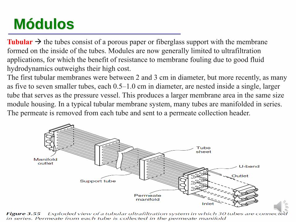
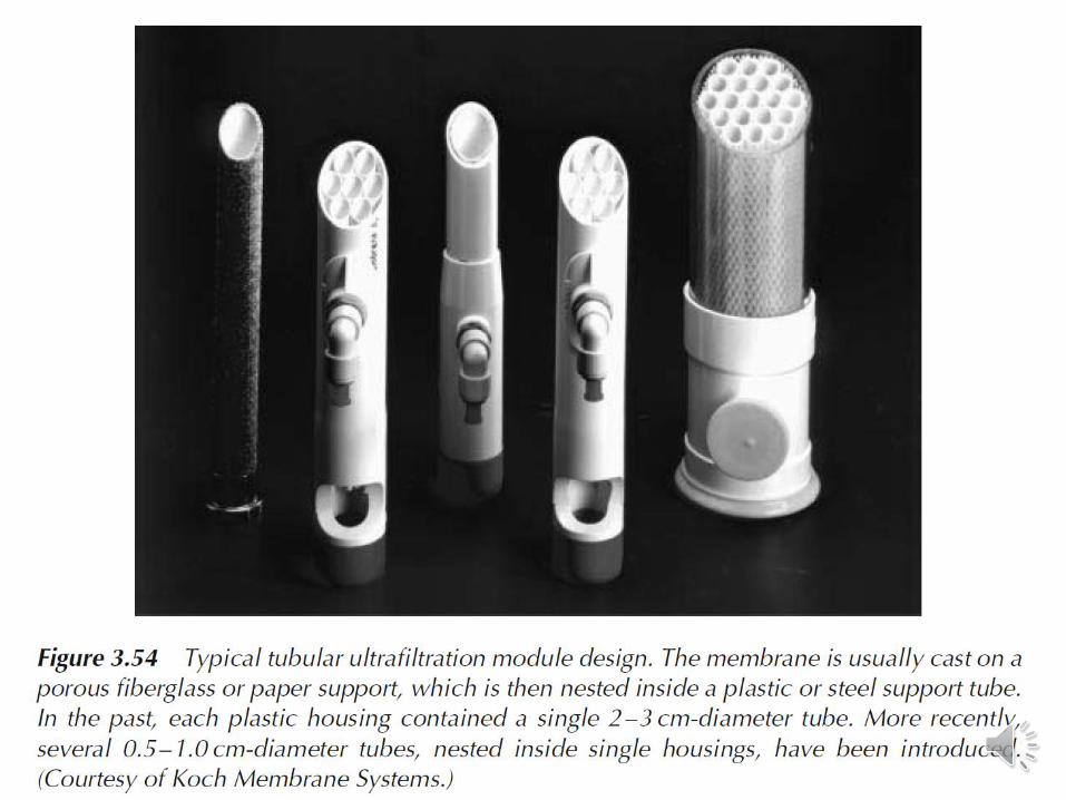
MódulosTubular→ the tubes consist of a porous paper or fiberglass support with the membrane
formed on the inside of the tubes. Modules are now generally limited to ultrafiltration
applications, for which the benefit of resistance to membrane fouling due to good fluid
hydrodynamics outweighs their high cost.
The first tubular membranes were between 2 and 3 cm in diameter, but more recently, as many
as five to seven smaller tubes, each 0.5–1.0 cm in diameter, are nested inside a single, larger
tube that serves as the pressure vessel. This produces a larger membrane area in the same size
module housing. In a typical tubular membrane system, many tubes are manifolded in series.
The permeate is removed from each tube and sent to a permeate collection header.
MódulosTubular → the tubes consist of a porous paper or fiberglass support with the membrane formed
on the inside of the tubes. Modules are now generally limited to ultrafiltration applications, for
which the benefit of resistance to membrane fouling due to good fluid hydrodynamics
outweighs their high cost.
The first tubular membranes were between 2 and 3 cm in diameter, but more recently, as many
as five to seven smaller tubes, each 0.5–1.0 cm in diameter, are nested inside a single, larger
tube that serves as the pressure vessel. This produces a larger membrane area in the same size
module housing. In a typical tubular membrane system, many tubes are manifolded in series.
The permeate is removed from each tube and sent to a permeate collection header.
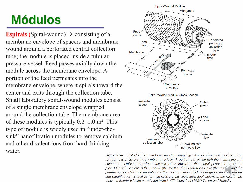
MódulosEspirais (Spiral-wound) → consisting of a
membrane envelope of spacers and membrane
wound around a perforated central collection
tube; the module is placed inside a tubular
pressure vessel. Feed passes axially down the
module across the membrane envelope. A
portion of the feed permeates into the
membrane envelope, where it spirals toward the
center and exits through the collection tube.
Small laboratory spiral-wound modules consist
of a single membrane envelope wrapped
around the collection tube. The membrane area
of these modules is typically 0.2–1.0 m². This
type of module is widely used in “under-the-
sink” nanofiltration modules to remove calcium
and other divalent ions from hard drinking
water.
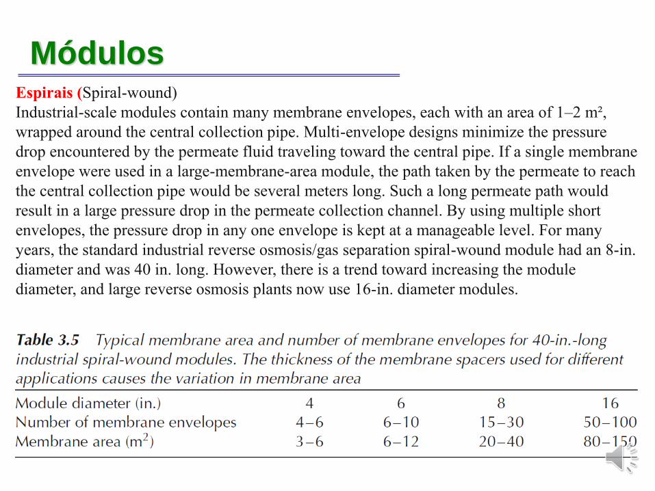
MódulosEspirais (Spiral-wound)
Industrial-scale modules contain many membrane envelopes, each with an area of 1–2 m²,
wrapped around the central collection pipe. Multi-envelope designs minimize the pressure
drop encountered by the permeate fluid traveling toward the central pipe. If a single membrane
envelope were used in a large-membrane-area module, the path taken by the permeate to reach
the central collection pipe would be several meters long. Such a long permeate path would
result in a large pressure drop in the permeate collection channel. By using multiple short
envelopes, the pressure drop in any one envelope is kept at a manageable level. For many
years, the standard industrial reverse osmosis/gas separation spiral-wound module had an 8-in.
diameter and was 40 in. long. However, there is a trend toward increasing the module
diameter, and large reverse osmosis plants now use 16-in. diameter modules.
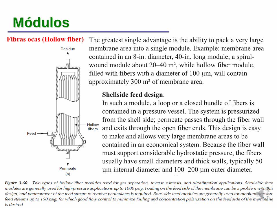
MódulosFibras ocas (Hollow fiber)
Shellside feed design.
In such a module, a loop or a closed bundle of fibers is
contained in a pressure vessel. The system is pressurized
from the shell side; permeate passes through the fiber wall
and exits through the open fiber ends. This design is easy
to make and allows very large membrane areas to be
contained in an economical system. Because the fiber wall
must support considerable hydrostatic pressure, the fibers
usually have small diameters and thick walls, typically 50
µm internal diameter and 100–200 µm outer diameter.
The greatest single advantage is the ability to pack a very large
membrane area into a single module. Example: membrane area
contained in an 8-in. diameter, 40-in. long module; a spiral-
wound module about 20–40 m², while hollow fiber module,
filled with fibers with a diameter of 100 µm, will contain
approximately 300 m² of membrane area.
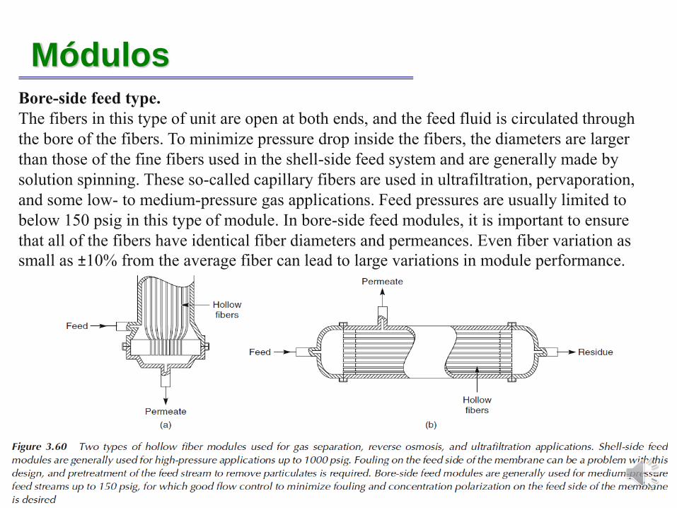
MódulosFibras ocas (Hollow fiber)Bore-side feed type.
The fibers in this type of unit are open at both ends, and the feed fluid is circulated through
the bore of the fibers. To minimize pressure drop inside the fibers, the diameters are larger
than those of the fine fibers used in the shell-side feed system and are generally made by
solution spinning. These so-called capillary fibers are used in ultrafiltration, pervaporation,
and some low- to medium-pressure gas applications. Feed pressures are usually limited to
below 150 psig in this type of module. In bore-side feed modules, it is important to ensure
that all of the fibers have identical fiber diameters and permeances. Even fiber variation as
small as ±10% from the average fiber can lead to large variations in module performance.
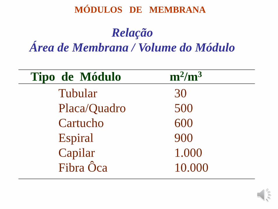
MÓDULOS DE MEMBRANA
Relação
Área de Membrana / Volume do Módulo
Tipo de Módulo m2/m3
Tubular 30
Placa/Quadro 500
Cartucho 600
Espiral 900
Capilar 1.000
Fibra Ôca 10.000
Módulos
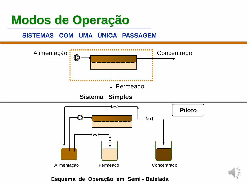
Modos de OperaçãoSISTEMAS COM UMA ÚNICA PASSAGEM
Sistema Simples
Alimentação Permeado Concentrado
Esquema de Operação em Semi - Batelada
Piloto
Concentrado
Permeado
Alimentação
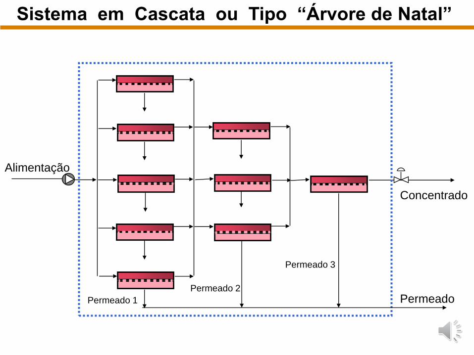
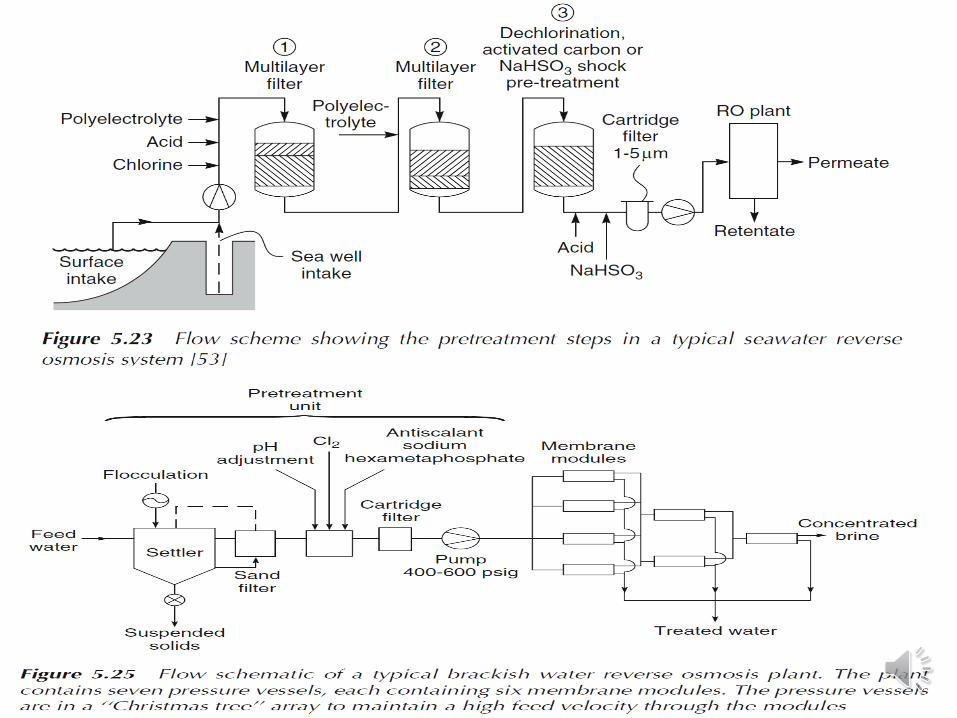
Sistema em Cascata ou Tipo “Árvore de Natal”
Alimentação
Permeado 3
Permeado 2
Permeado 1
Concentrado
Permeado
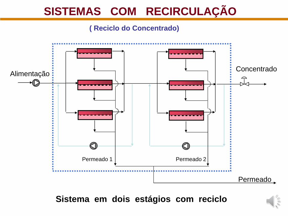
Sistema em dois estágios com reciclo
SISTEMAS COM RECIRCULAÇÃO
AlimentaçãoConcentrado
Permeado 1 Permeado 2
Permeado
( Reciclo do Concentrado)
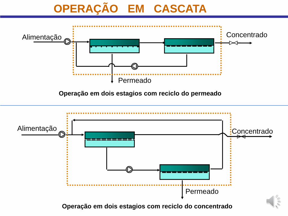
Operação em dois estagios com reciclo do concentrado
Operação em dois estagios com reciclo do permeado
OPERAÇÃO EM CASCATA
Permeado
ConcentradoAlimentação
Permeado
ConcentradoAlimentação
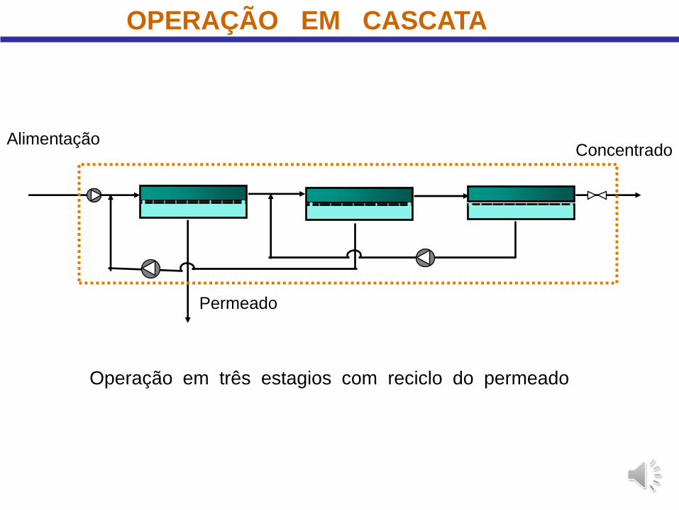
OPERAÇÃO EM CASCATA
Operação em três estagios com reciclo do permeado
AlimentaçãoConcentrado
Permeado
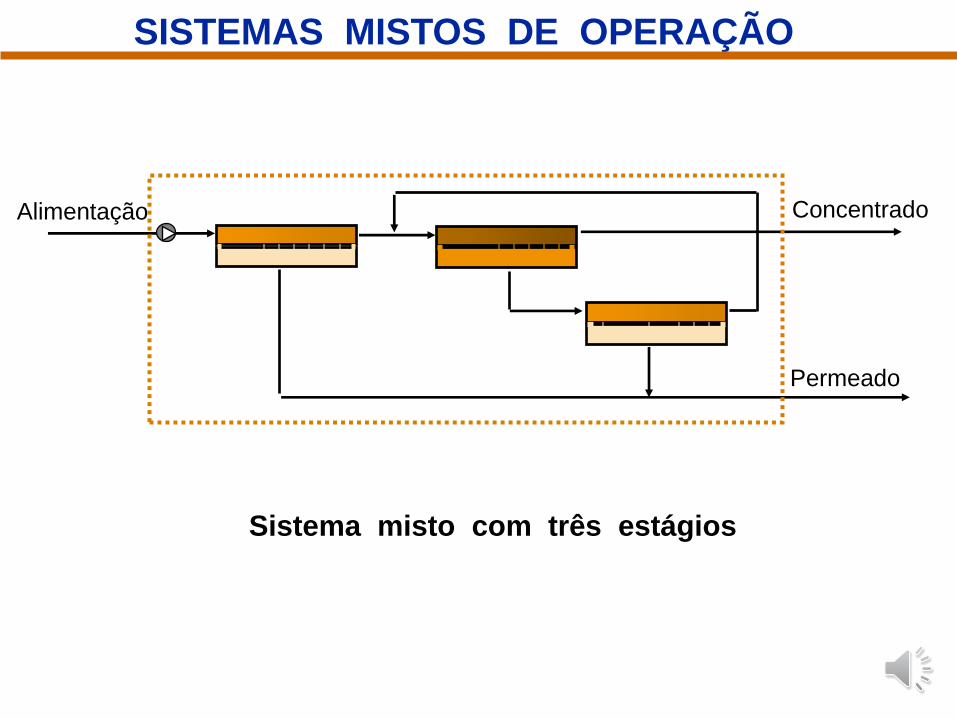
Sistema misto com três estágios
Alimentação Concentrado
Permeado
SISTEMAS MISTOS DE OPERAÇÃO
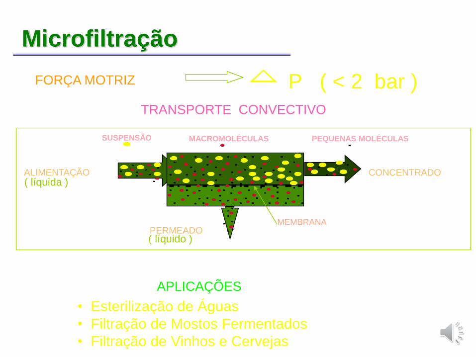
Microfiltração
FORÇA MOTRIZ P ( < 2 bar )
TRANSPORTE CONVECTIVO
ALIMENTAÇÃO
PERMEADOMEMBRANA
CONCENTRADO
MACROMOLÉCULAS PEQUENAS MOLÉCULASSUSPENSÃO
( líquida )
( líquido )
APLICAÇÕES
• Esterilização de Águas
• Filtração de Mostos Fermentados
• Filtração de Vinhos e Cervejas R.Nobrega
COPPE/UFRJ
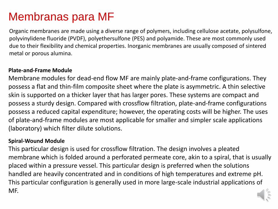
Membranas para MFOrganic membranes are made using a diverse range of polymers, including cellulose acetate, polysulfone, polyvinylidene fluoride (PVDF), polyethersulfone (PES) and polyamide. These are most commonly used due to their flexibility and chemical properties. Inorganic membranes are usually composed of sintered metal or porous alumina.
Plate-and-Frame Module
Membrane modules for dead-end flow MF are mainly plate-and-frame configurations. They possess a flat and thin-film composite sheet where the plate is asymmetric. A thin selective skin is supported on a thicker layer that has larger pores. These systems are compact and possess a sturdy design. Compared with crossflow filtration, plate-and-frame configurations possess a reduced capital expenditure; however, the operating costs will be higher. The uses of plate-and-frame modules are most applicable for smaller and simpler scale applications (laboratory) which filter dilute solutions.
Spiral-Wound Module
This particular design is used for crossflow filtration. The design involves a pleated membrane which is folded around a perforated permeate core, akin to a spiral, that is usually placed within a pressure vessel. This particular design is preferred when the solutions handled are heavily concentrated and in conditions of high temperatures and extreme pH.This particular configuration is generally used in more large-scale industrial applications of MF.
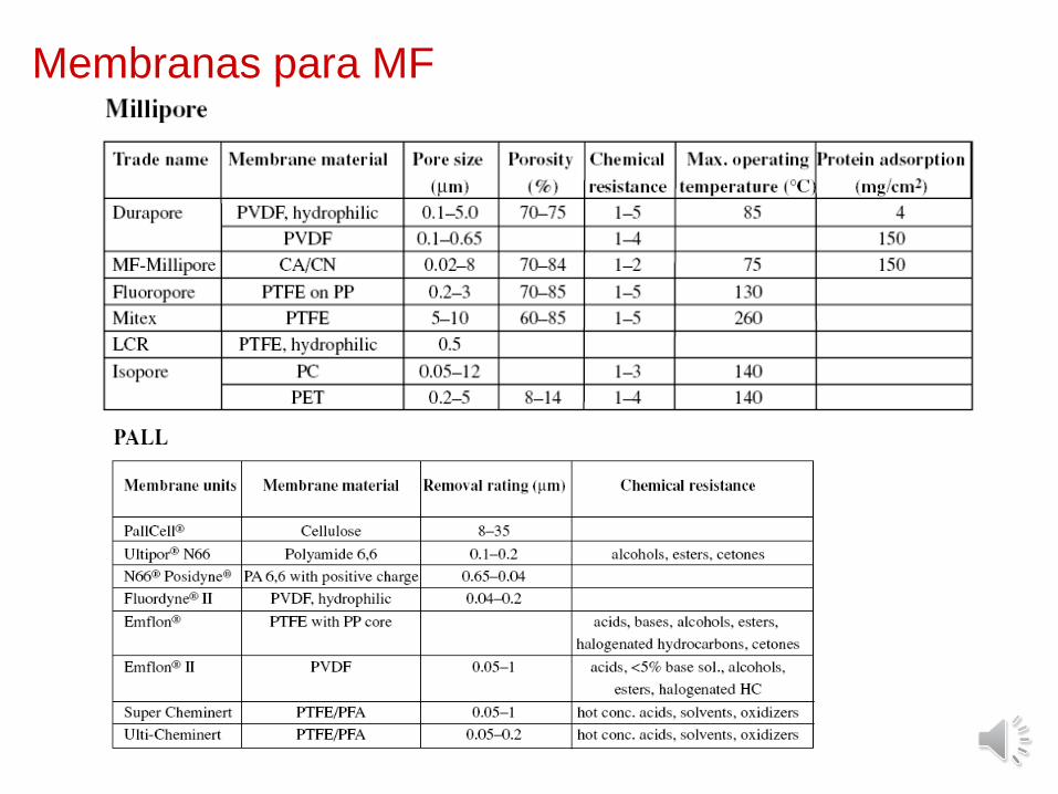
Membranas para MF
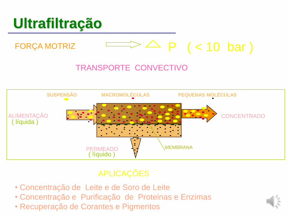
Ultrafiltração
ALIMENTAÇÃO CONCENTRADO
PERMEADO MEMBRANA
SUSPENSÃO MACROMOLÉCULAS PEQUENAS MOLÉCULAS
( líquida )
( líquido )
FORÇA MOTRIZ P ( < 10 bar )
TRANSPORTE CONVECTIVO
APLICAÇÕES
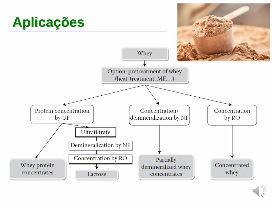
• Concentração de Leite e de Soro de Leite
• Concentração e Purificação de Proteinas e Enzimas
• Recuperação de Corantes e Pigmentos
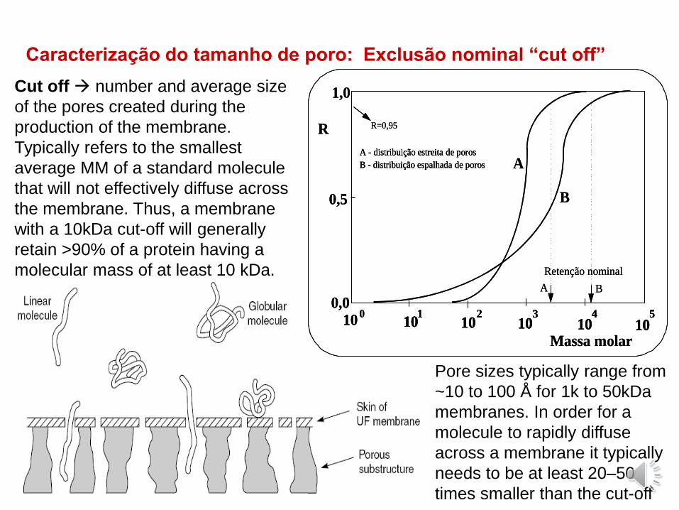
Caracterização do tamanho de poro: Exclusão nominal “cut off”
A - distribuição estreita de poros
B - distribuição espalhada de poros A
B
101
102
103
104
105
100
Massa molar
0,0
1,0
0,5
R R=0,95
Retenção nominal
A B
A - distribuição estreita de poros
B - distribuição espalhada de poros
A - distribuição estreita de poros
B - distribuição espalhada de poros A
B
101
101
102
102
103
103
104
104
105
105
100
Massa molar
0,0
1,0
0,5
R R=0,95
Retenção nominal
A B
Cut off → number and average size
of the pores created during the
production of the membrane.
Typically refers to the smallest
average MM of a standard molecule
that will not effectively diffuse across
the membrane. Thus, a membrane
with a 10kDa cut-off will generally
retain >90% of a protein having a
molecular mass of at least 10 kDa.
Pore sizes typically range from
~10 to 100 Å for 1k to 50kDa
membranes. In order for a
molecule to rapidly diffuse
across a membrane it typically
needs to be at least 20–50
times smaller than the cut-off
Membranas para UFThere are two kinds of organic membranes used: polymers (regenerated cellulose, cellulose acetate (CA), cellulose nitrate, polyacrylonitrile,poly(vinylidene fluoride) polyimide, polysulfone, polyethersulfone) and inorganic membranes using inorganic materials represented by ceramics.
Because they are lighter than inorganic membranes, they are easy to handle, are generally cheap and it is easy to prepare various module membranes, but their usable temperature range is small and their chemical resistance is weak.
Inorganic membrane has a pore size distribution that is sharper than an organic thin membrane, and can be used at elevated temperature and pressure. After mixing it with binders, and having moulded ceramic particles such as alumina, mullite and titania, it is easy to form a porous structure with high ratio surface area by hardening it at a high temperature. A tubular shape with coarse particles is formed, and asymmetric ceramic separation membranes can be prepared by coating several layers with fine particles on this tubular support. Inorganic membranes are relatively expensive and not high in strength.
Membranas para UF
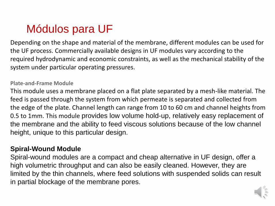
Módulos para UFDepending on the shape and material of the membrane, different modules can be used for the UF process. Commercially available designs in UF modules vary according to the required hydrodynamic and economic constraints, as well as the mechanical stability of the system under particular operating pressures.
Plate-and-Frame Module
This module uses a membrane placed on a flat plate separated by a mesh-like material. The feed is passed through the system from which permeate is separated and collected from the edge of the plate. Channel length can range from 10 to 60 cm and channel heights from 0.5 to 1mm. This module provides low volume hold-up, relatively easy replacement of
the membrane and the ability to feed viscous solutions because of the low channel
height, unique to this particular design.
Spiral-Wound Module
Spiral-wound modules are a compact and cheap alternative in UF design, offer a
high volumetric throughput and can also be easily cleaned. However, they are
limited by the thin channels, where feed solutions with suspended solids can result
in partial blockage of the membrane pores.
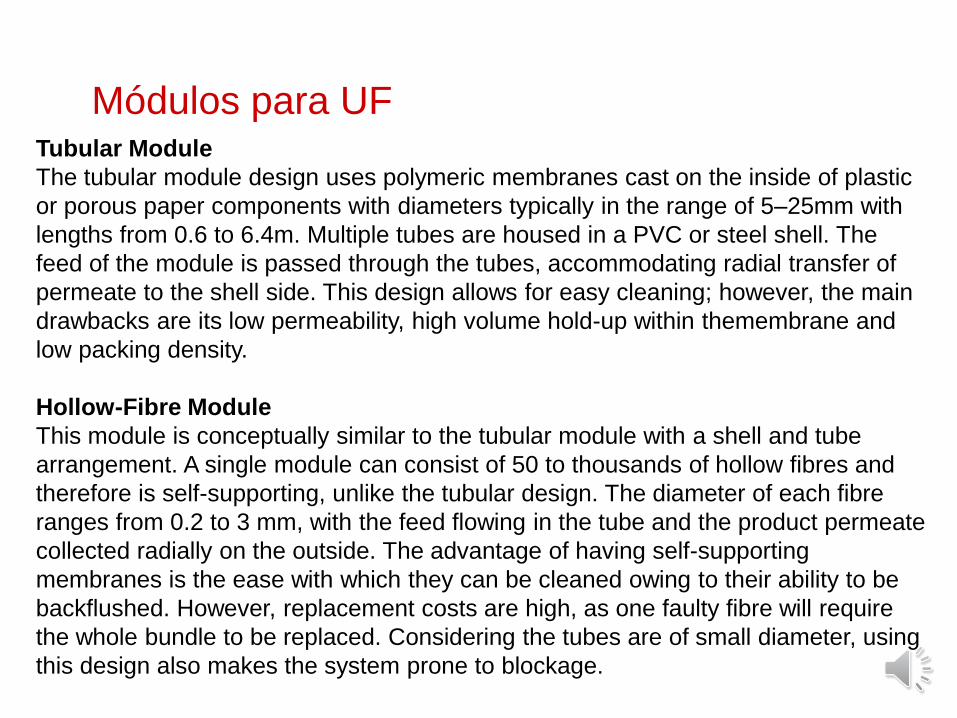
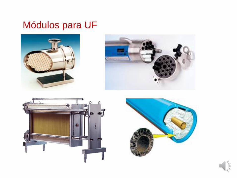
Módulos para UFTubular Module
The tubular module design uses polymeric membranes cast on the inside of plastic
or porous paper components with diameters typically in the range of 5–25mm with
lengths from 0.6 to 6.4m. Multiple tubes are housed in a PVC or steel shell. The
feed of the module is passed through the tubes, accommodating radial transfer of
permeate to the shell side. This design allows for easy cleaning; however, the main
drawbacks are its low permeability, high volume hold-up within themembrane and
low packing density.
Hollow-Fibre Module
This module is conceptually similar to the tubular module with a shell and tube
arrangement. A single module can consist of 50 to thousands of hollow fibres and
therefore is self-supporting, unlike the tubular design. The diameter of each fibre
ranges from 0.2 to 3 mm, with the feed flowing in the tube and the product permeate
collected radially on the outside. The advantage of having self-supporting
membranes is the ease with which they can be cleaned owing to their ability to be
backflushed. However, replacement costs are high, as one faulty fibre will require
the whole bundle to be replaced. Considering the tubes are of small diameter, using
this design also makes the system prone to blockage.
Módulos para UF
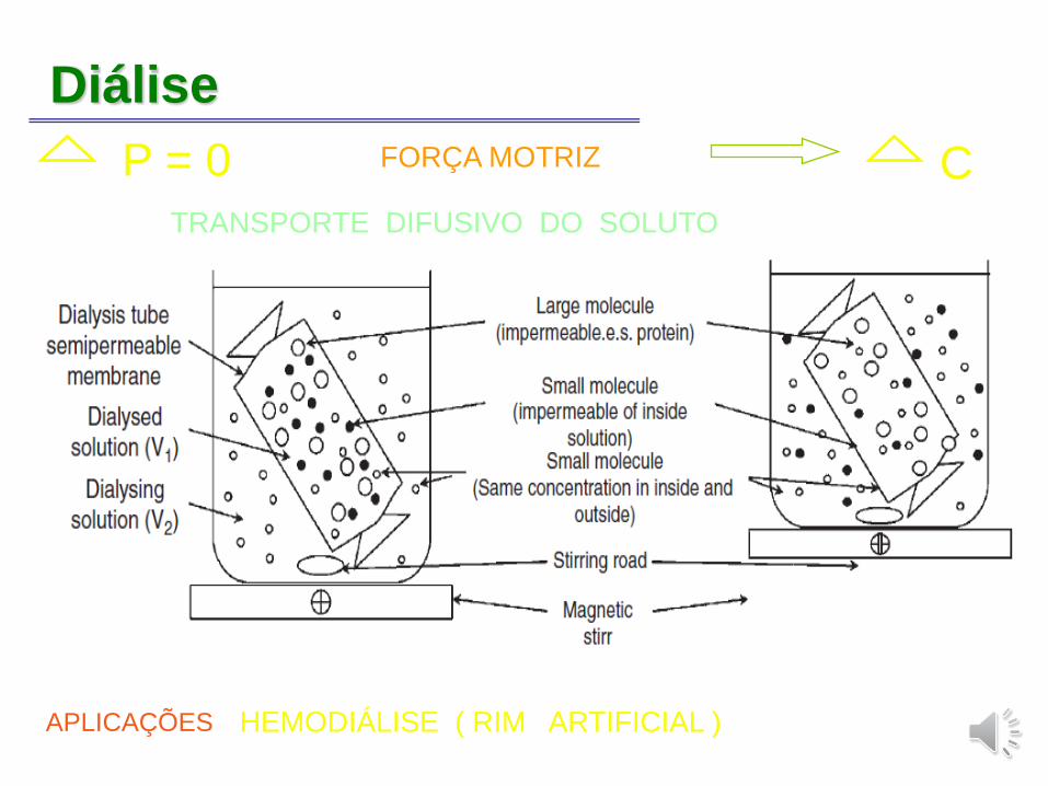
Diálise
P = 0 FORÇA MOTRIZ CTRANSPORTE DIFUSIVO DO SOLUTO
APLICAÇÕES HEMODIÁLISE ( RIM ARTIFICIAL )
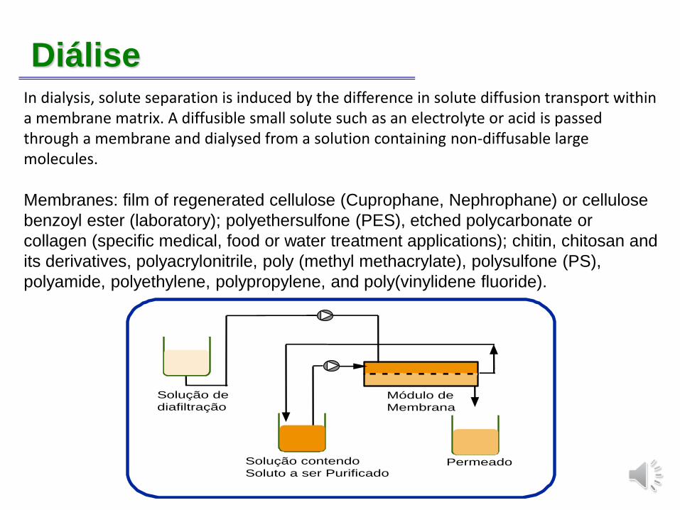
DiáliseIn dialysis, solute separation is induced by the difference in solute diffusion transport within a membrane matrix. A diffusible small solute such as an electrolyte or acid is passed through a membrane and dialysed from a solution containing non-diffusable large molecules.
Membranes: film of regenerated cellulose (Cuprophane, Nephrophane) or cellulose
benzoyl ester (laboratory); polyethersulfone (PES), etched polycarbonate or
collagen (specific medical, food or water treatment applications); chitin, chitosan and
its derivatives, polyacrylonitrile, poly (methyl methacrylate), polysulfone (PS),
polyamide, polyethylene, polypropylene, and poly(vinylidene fluoride).
Solução de
diafiltração
PermeadoSolução contendo
Soluto a ser Purificado
Módulo de
Membrana
Diálise
Nanofiltração
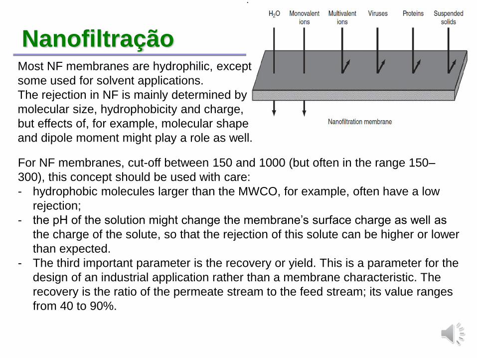
For NF membranes, cut-off between 150 and 1000 (but often in the range 150–
300), this concept should be used with care:
- hydrophobic molecules larger than the MWCO, for example, often have a low
rejection;
- the pH of the solution might change the membrane’s surface charge as well as
the charge of the solute, so that the rejection of this solute can be higher or lower
than expected.
- The third important parameter is the recovery or yield. This is a parameter for the
design of an industrial application rather than a membrane characteristic. The
recovery is the ratio of the permeate stream to the feed stream; its value ranges
from 40 to 90%.
Most NF membranes are hydrophilic, except
some used for solvent applications.
The rejection in NF is mainly determined by
molecular size, hydrophobicity and charge,
but effects of, for example, molecular shape
and dipole moment might play a role as well.
Nanofiltração
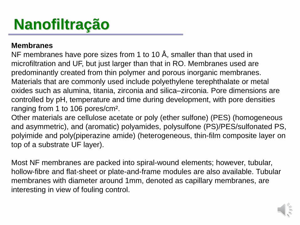
Membranes
NF membranes have pore sizes from 1 to 10 Å, smaller than that used in
microfiltration and UF, but just larger than that in RO. Membranes used are
predominantly created from thin polymer and porous inorganic membranes.
Materials that are commonly used include polyethylene terephthalate or metal
oxides such as alumina, titania, zirconia and silica–zirconia. Pore dimensions are
controlled by pH, temperature and time during development, with pore densities
ranging from 1 to 106 pores/cm².
Other materials are cellulose acetate or poly (ether sulfone) (PES) (homogeneous
and asymmetric), and (aromatic) polyamides, polysulfone (PS)/PES/sulfonated PS,
polyimide and poly(piperazine amide) (heterogeneous, thin-film composite layer on
top of a substrate UF layer).
Most NF membranes are packed into spiral-wound elements; however, tubular,
hollow-fibre and flat-sheet or plate-and-frame modules are also available. Tubular
membranes with diameter around 1mm, denoted as capillary membranes, are
interesting in view of fouling control.
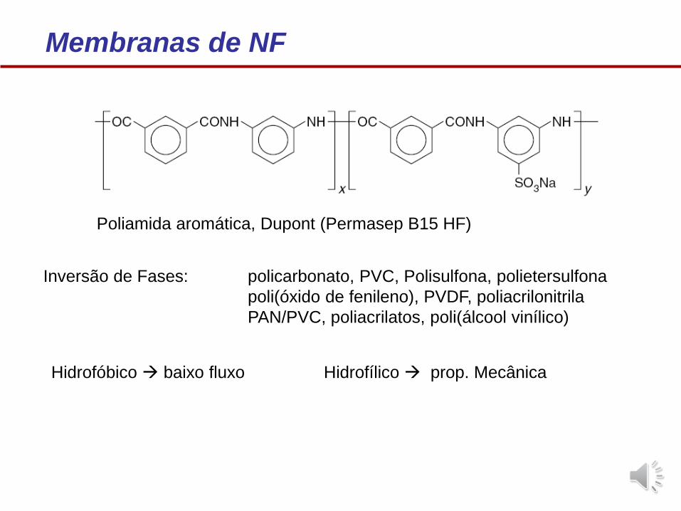
Membranas de NF
Poliamida aromática, Dupont (Permasep B15 HF)
Inversão de Fases: policarbonato, PVC, Polisulfona, polietersulfona
poli(óxido de fenileno), PVDF, poliacrilonitrila
PAN/PVC, poliacrilatos, poli(álcool vinílico)
Hidrofóbico → baixo fluxo Hidrofílico → prop. Mecânica
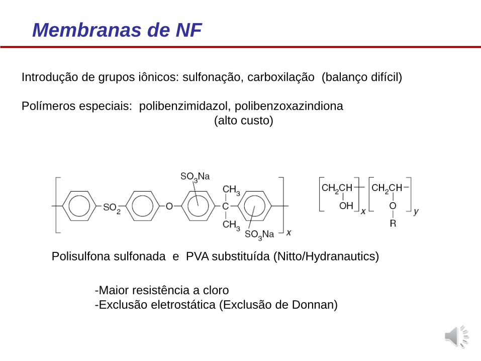
Introdução de grupos iônicos: sulfonação, carboxilação (balanço difícil)
Polímeros especiais: polibenzimidazol, polibenzoxazindiona
(alto custo)
Membranas de NF
Polisulfona sulfonada e PVA substituída (Nitto/Hydranautics)
-Maior resistência a cloro
-Exclusão eletrostática (Exclusão de Donnan)
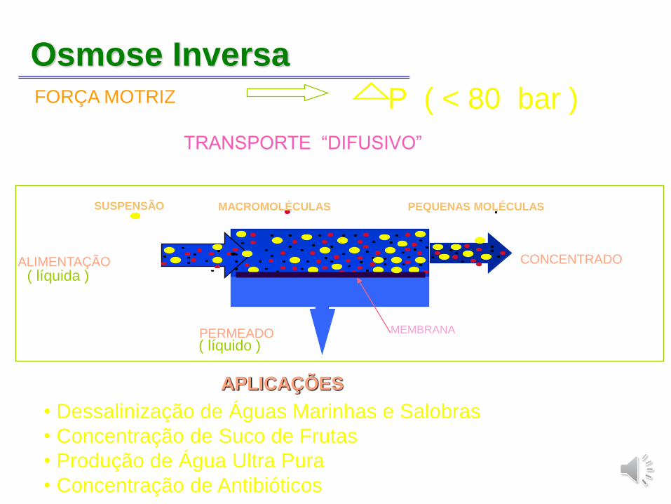
Osmose InversaFORÇA MOTRIZ P ( < 80 bar )
TRANSPORTE “DIFUSIVO”
APLICAÇÕES
ALIMENTAÇÃO
PERMEADO MEMBRANA
CONCENTRADO
MACROMOLÉCULAS PEQUENAS MOLÉCULAS SUSPENSÃO
( líquida )
( líquido )
• Dessalinização de Águas Marinhas e Salobras
• Concentração de Suco de Frutas
• Produção de Água Ultra Pura
• Concentração de Antibióticos
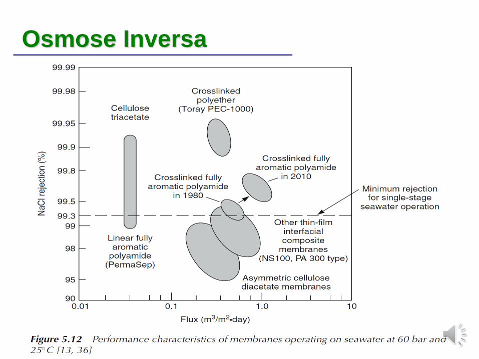
Osmose Inversa
Osmose Inversa
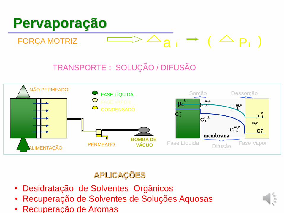
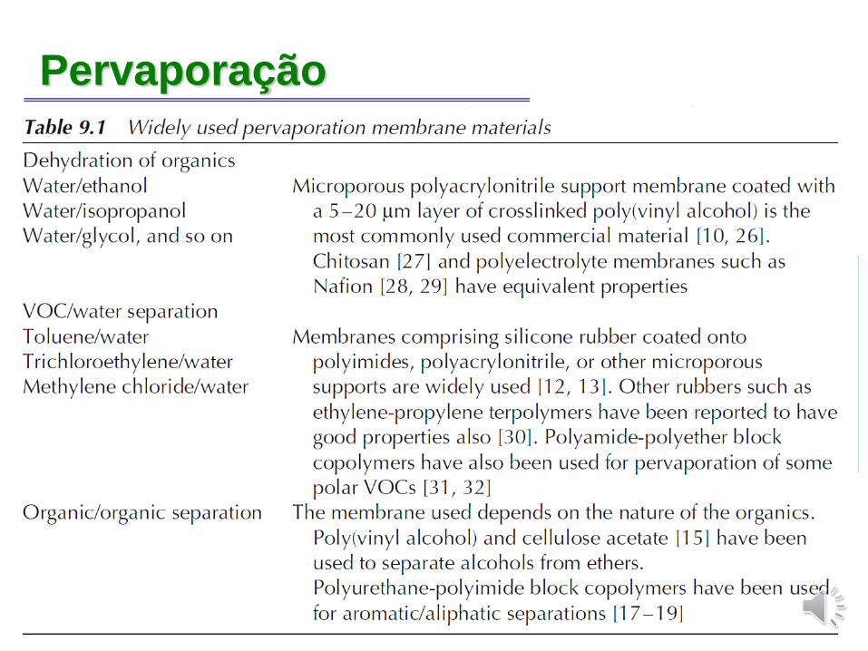
PervaporaçãoFORÇA MOTRIZ a i P i( )
TRANSPORTE : SOLUÇÃO / DIFUSÃO
APLICAÇÕES
• Desidratação de Solventes Orgânicos
• Recuperação de Solventes de Soluções Aquosas
• Recuperação de Aromas
ALIMENTAÇÃOPERMEADO
FASE LÍQUIDA
FASE VAPOR
CONDENSADO
BOMBA DE
VÁCUO
NÃO PERMEADO Sorção Dessorção
1m,v
membrana
DifusãoFase VaporFase Líquida
1L
LC1
m,V1C
m,L1C
L1C 1
V
1
m,v
m,L
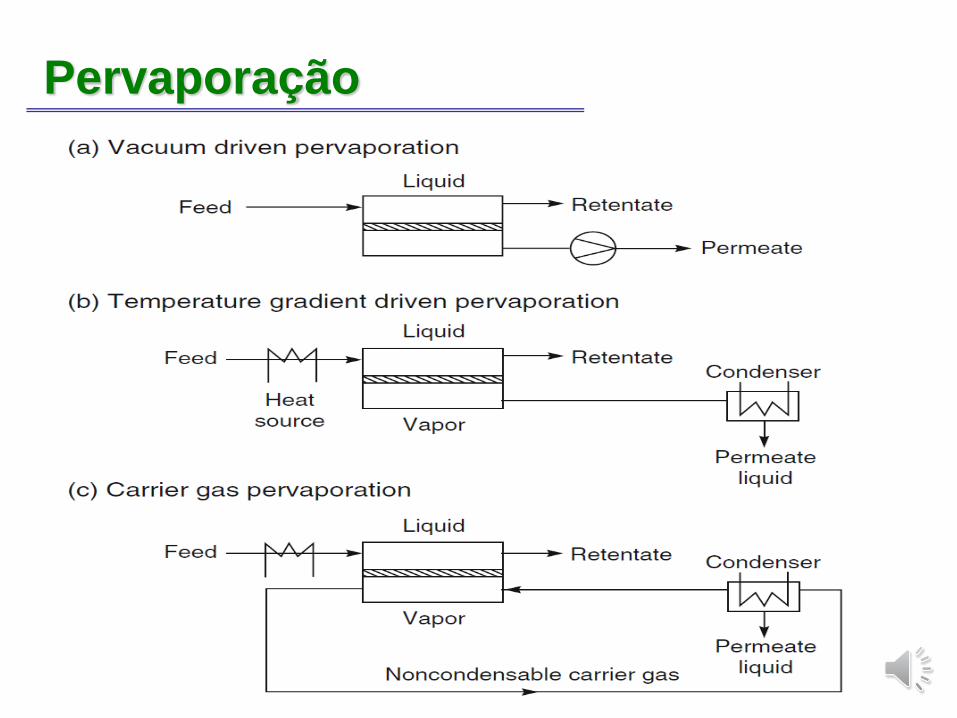
Pervaporação
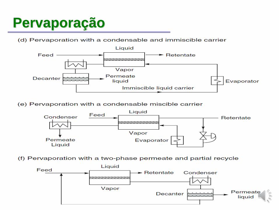
Pervaporação
PervaporaçãoFORÇA MOTRIZ a i P i( )
TRANSPORTE : SOLUÇÃO / DIFUSÃO
APLICAÇÕES
• Desidratação de Solventes Orgânicos
• Recuperação de Solventes de Soluções Aquosas
• Recuperação de Aromas
ALIMENTAÇÃOPERMEADO
FASE LÍQUIDA
FASE VAPOR
CONDENSADO
BOMBA DE
VÁCUO
NÃO PERMEADO Sorção Dessorção
1m,v
membrana
DifusãoFase VaporFase Líquida
1L
LC1
m,V1C
m,L1C
L1C 1
V
1
m,v
m,L
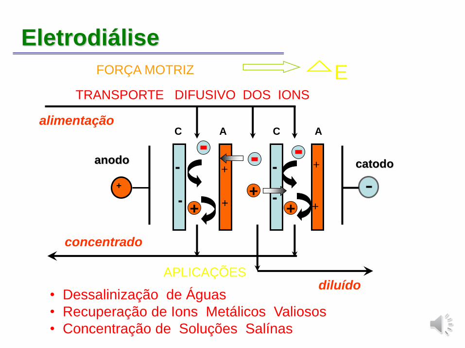
Eletrodiálise
APLICAÇÕES
FORÇA MOTRIZ ETRANSPORTE DIFUSIVO DOS IONS
• Dessalinização de Águas
• Recuperação de Ions Metálicos Valiosos
• Concentração de Soluções Salínas
concentrado
anodo catodo
C A C Aalimentação
diluído
+
+
+ ++ +
+
+
Eletrodiálise
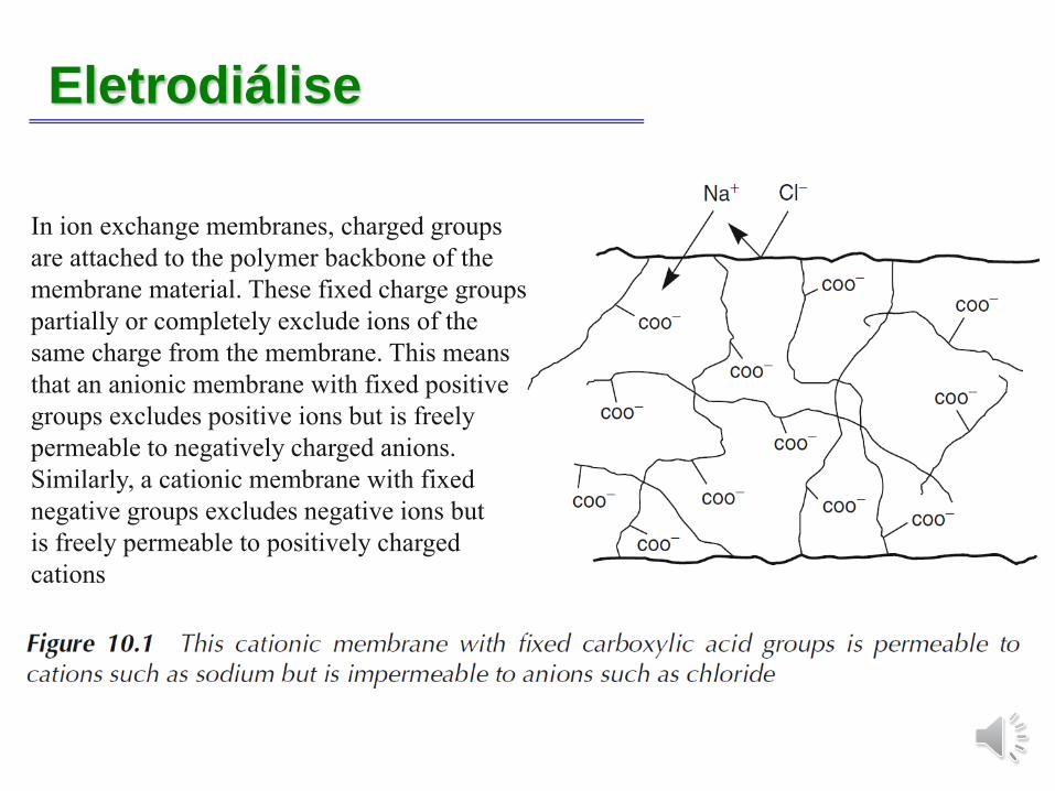
In ion exchange membranes, charged groups
are attached to the polymer backbone of the
membrane material. These fixed charge groups
partially or completely exclude ions of the
same charge from the membrane. This means
that an anionic membrane with fixed positive
groups excludes positive ions but is freely
permeable to negatively charged anions.
Similarly, a cationic membrane with fixed
negative groups excludes negative ions but
is freely permeable to positively charged
cations
EletrodiáliseIon exchange membranes contain a high concentration of fixed ionic groups, typically 3–4
meq/g or more. When placed in water, these ionic groups tend to absorb water; charge
repulsion of the ionic groups can then cause the membrane to swell excessively. This is why
most ion exchange membranes are highly crosslinked to limit swelling.
However, high crosslinking densities make polymers brittle, so the membranes are usually
stored and handled wet to allow absorbed water to plasticize the membrane. Most ion
exchange membranes are produced as homogenous films 50–200 μm thick. The membrane is
often reinforced by casting onto a net or fabric to maintain the shape and to minimize
swelling.
Ion exchange membranes fall into two broad categories: homogeneous and heterogeneous.
In homogeneous membranes, the charged groups are uniformly distributed through the
membrane matrix. These membranes swell relatively uniformly when exposed to water, the
extent of swelling being controlled by their crosslinking density. A number of early
homogeneous membranes were made by simple condensation reactions of suitable
monomers, such as phenol–formaldehyde condensation reactions. Other important category
is the perfluorocarbon type made by DuPont (trade name NafionR). The base polymer is
made by polymerization of a sulfinol fluoride vinyl ether with tetrafluoroethylene. The
copolymer formed is extruded as films about 120 μm thick, after which the sulfinol fluoride
groups are hydrolyzed to form sulfonic acid groups.
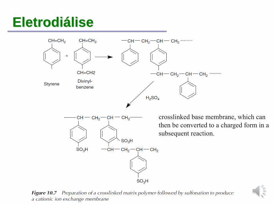
Eletrodiálise
crosslinked base membrane, which can
then be converted to a charged form in a
subsequent reaction.
Eletrodiálise
Eletrodiálise
In heterogeneous membranes, the ion exchange groups are contained in small domains
distributed throughout an inert support matrix, which provides mechanical strength.
Heterogeneous membranes can be made, for example, by dispersing finely ground ion
exchange particles in a polymer support matrix. In recent years, finely dispersed
heterogeneous membranes have been made by casting membrane films from ABA block
copolymers. The membrane film is then chemically treated to introduce fixed charges into
one of the phase separated domains. This domain forms the ion conducting path through the
membrane. Because of the difference in the degree of swelling between the ion exchange
portion and the inert portion of heterogeneous membranes, mechanical failure, leading to
leaks at the boundary between the two domains, can be a problem. For example, very finely
powdered cation or anion exchange particles uniformly dispersed in polypropylene.
A much finer heterogeneous dispersion of ion exchange particles, and consequently a more
stable membrane, can be made with a poly(vinyl chloride) (PVC) plastisol. A plastisol of
approximately equal parts PVC, styrene monomer, and crosslinking agent in a dioctyl
phthalate plasticizing solvent is prepared. The mixture is then cast and polymerized as a film.
The PVC and polystyrene polymers form an interconnected domain structure. The styrene
groups are then sulfonated by treatment with concentrated sulfuric acid or sulfur trioxide to
form a very finely dispersed but heterogeneous structure of sulfonated polystyrene in a PVC
matrix, which provides toughness and strength.
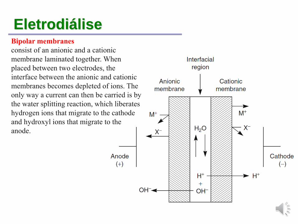
EletrodiáliseBipolar membranes
consist of an anionic and a cationic
membrane laminated together. When
placed between two electrodes, the
interface between the anionic and cationic
membranes becomes depleted of ions. The
only way a current can then be carried is by
the water splitting reaction, which liberates
hydrogen ions that migrate to the cathode
and hydroxyl ions that migrate to the
anode.
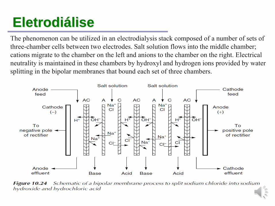
EletrodiáliseThe phenomenon can be utilized in an electrodialysis stack composed of a number of sets of
three-chamber cells between two electrodes. Salt solution flows into the middle chamber;
cations migrate to the chamber on the left and anions to the chamber on the right. Electrical
neutrality is maintained in these chambers by hydroxyl and hydrogen ions provided by water
splitting in the bipolar membranes that bound each set of three chambers.
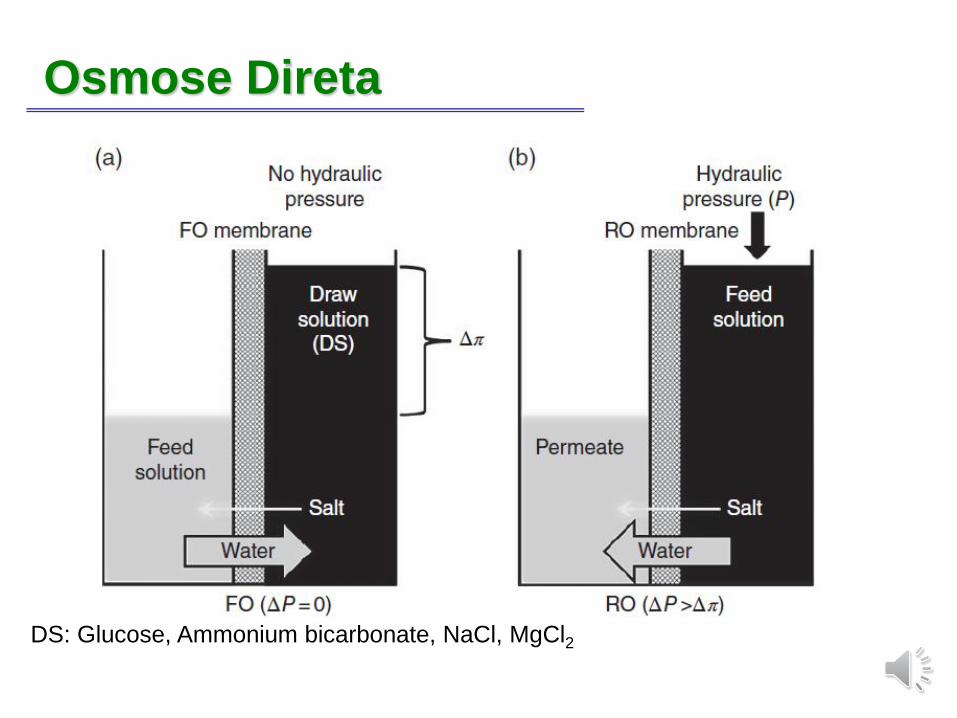
Osmose Direta
DS: Glucose, Ammonium bicarbonate, NaCl, MgCl2
Osmose Direta
On the other hand, when an aqueous salt solution such as MgCl2 is used as a DS in FO, a driving force of 1000 atm is provided by an aqueous solute of 5 M MgCl2 [1]. Thus, water conversion is possible with a high recovery of more than 80% from highly concentrated salt water solution such as the seawater under atmospheric pressure without using a high-pressure pump in FO. In addition, as with RO, one of the problems in the water processingsystem with the separation membrane includes a drop in processing capacity as a result of membrane fouling. However, even when the same water permeability is provided, because hydraulic pressure is not applied in FO there are less collisions of molecules with the membrane wall than in RO, and the adsorption characteristics of the membrane pollutant at the film surface are lower than for an RO membrane. Therefore, detachment of the membrane pollutant is possible by physical washing.
The fundamental performances which are demanded for FO membranes are follows: (1) high water permeability through the active layer, (2) low salt permeability through the active layer and (3) structure of the support layer with low internal concentration polarization (ICP).
Generally, any dense, nonporous, selectively permeable material can be used. Membranes in flat sheet and capillary configurations have been tested for various applications of FO.
Extração por MembranasIntroduction
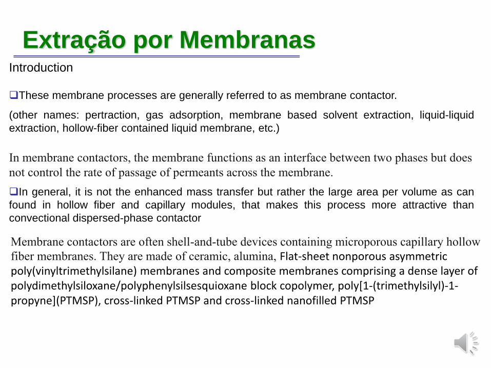
❑These membrane processes are generally referred to as membrane contactor.
(other names: pertraction, gas adsorption, membrane based solvent extraction, liquid-liquid
extraction, hollow-fiber contained liquid membrane, etc.)
In membrane contactors, the membrane functions as an interface between two phases but does
not control the rate of passage of permeants across the membrane.
❑In general, it is not the enhanced mass transfer but rather the large area per volume as can
found in hollow fiber and capillary modules, that makes this process more attractive than
convectional dispersed-phase contactor
Membrane contactors are often shell-and-tube devices containing microporous capillary hollow
fiber membranes. They are made of ceramic, alumina, Flat-sheet nonporous asymmetricpoly(vinyltrimethylsilane) membranes and composite membranes comprising a dense layer ofpolydimethylsiloxane/polyphenylsilsesquioxane block copolymer, poly[1-(trimethylsilyl)-1-propyne](PTMSP), cross-linked PTMSP and cross-linked nanofilled PTMSP
Extração por MembranasIntroduction
❑These membrane processes are generally referred to as membrane contactor.
(other names: pertraction, gas adsorption, membrane based solvent extraction, liquid-liquid
extraction, hollow-fiber contained liquid membrane, etc.)
In membrane contactors, the membrane functions as an interface between two phases but does
not control the rate of passage of permeants across the membrane.
❑In general, it is not the enhanced mass transfer but rather the large area per volume as can
found in hollow fiber and capillary modules, that makes this process more attractive than
convectional dispersed-phase contactor
Membrane contactors are often shell-and-tube devices containing microporous capillary hollow
fiber membranes. The air-filled membrane pores are sufficiently small that capillary forces
prevent direct mixing of the liquid phases on either side of the membrane.
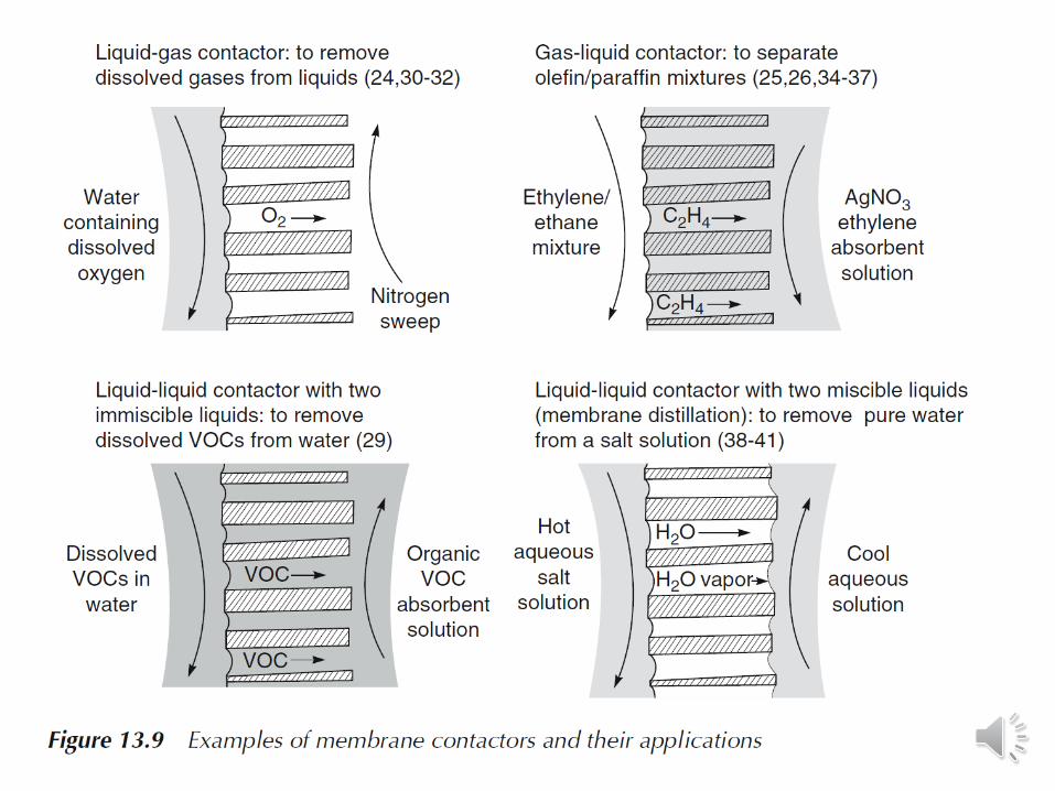
The membrane contactor shown in Figure 13.8 separates a liquid and a gas phase: this is
a liquid/gas contactor. Membrane contactors can also be used to separate two immiscible
liquids (liquid/liquid contactors) or two miscible liquids (usually called membrane distillation)
[23]. Contactors can also be used to selectively absorb one component from a gas
mixture into a liquid (gas/liquid contactors).
Destilação por MembranaIntroduction
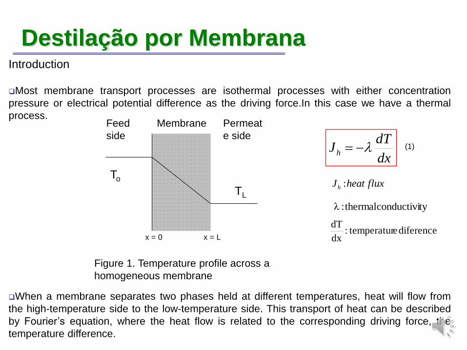
❑Most membrane transport processes are isothermal processes with either concentration
pressure or electrical potential difference as the driving force.In this case we have a thermal
process.
❑When a membrane separates two phases held at different temperatures, heat will flow from
the high-temperature side to the low-temperature side. This transport of heat can be described
by Fourier’s equation, where the heat flow is related to the corresponding driving force, the
temperature difference.
dx
dTJh −=
fluxheatJh :
tyconductivithermal:
diferenceetemperatur:dx
dT
(1)
Figure 1. Temperature profile across a
homogeneous membrane
Feed
side
Membrane Permeat
e side
To
TL
x = 0 x = L
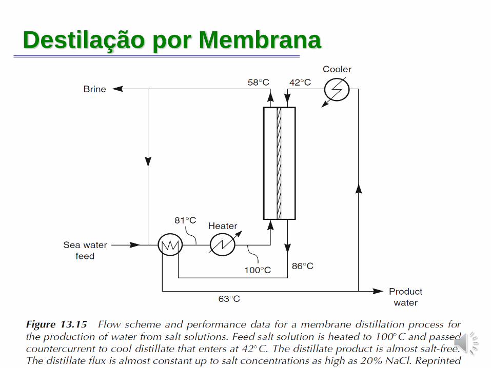
Destilação por MembranaType of liquid/liquid membrane contactors.
The hydrophobic microporous membrane is not wetted by either solution and forms a vapor
gap between the two solutions. Because the solutions are at different temperatures, their
vapor pressures are different; as a result, water vapor diffuses across the membrane. The
latent heat required to vaporize the water is removed from the feed solution, and is carried to
the permeate solution when the vapor condenses. Consequently, the feed solution cools, and
the permeate warms.
Membrane distillation offers a number of advantages over alternative pressure-driven
processes such as reverse osmosis. Because the process is driven by temperature gradients,
low-grade waste heat can be used and expensive high-pressure pumps are not required.
Membrane fluxes are comparable to reverse osmosis fluxes, so membrane areas are not
excessive. Finally, the process is still effective with slightly reduced fluxes even for
concentrated salt solutions. This is an advantage over reverse osmosis, in which the
feed solution osmotic pressure places a practical limit on the concentration of a salt in
the solution to be processed.
The principal application proposed for the technique is the separation of water from salt
solutions. In the 1980s, a research group at Enka, then a division of Akzo, developed
membrane distillation to the commercial scale using microporous polypropylene capillary
membrane modules.
Destilação por Membrana
Destilação por Membrana
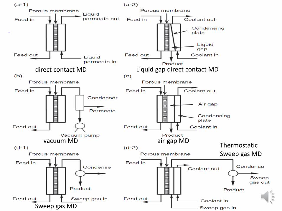
Sweep gas MD
direct contact MD
vacuum MD air-gap MD ThermostaticSweep gas MD
Liquid gap direct contact MD
Destilação por MembranaA large variety of membranes, including both polymeric and inorganic membranes of hydrophobic nature, can be used in the MD process; however, polymeric membranes have attracted much more attention owing to their possibility to modulate the intrinsic properties. PTFE (polytetrafluroethylene), polypropylene and polyvinylidenefluoride(PVDF) are the most commonly used polymeric membranes owing to their low surface tension values. The useful materials should be selected according to criteria that include compatibility with the liquids involved, cost, ease of fabrication and assembly, useful operating temperatures and thermal conductivity. Among them, PTFE membranes are the most hydrophobic ones, showing outstanding thermal stability and chemical resistance properties (they are not dissolved in all common solvents). The main disadvantage of PTFE membranes is the difficulty of processing. Polypropylene exhibits excellent solvent-resistant properties and high crystallinity. PVDF membranes exhibit good thermal and chemical resistance; however, this polymer easily dissolves at room temperature in a variety of solvents, including DMF and triethylphosphate.
There are two major MD module configurations, which are the plate-and-frame module (packing density is about 100 – 400 m²m-3) and the tubular module (3000 m²m-3).
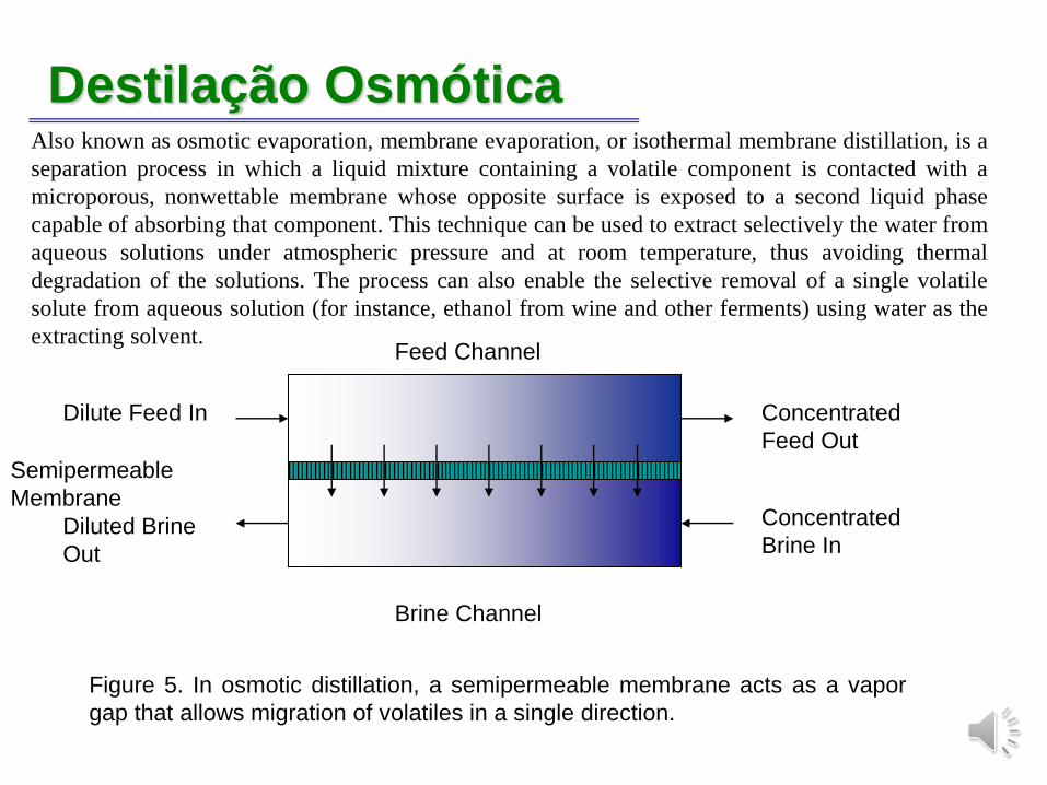
Destilação OsmóticaAlso known as osmotic evaporation, membrane evaporation, or isothermal membrane distillation, is a
separation process in which a liquid mixture containing a volatile component is contacted with a
microporous, nonwettable membrane whose opposite surface is exposed to a second liquid phase
capable of absorbing that component. This technique can be used to extract selectively the water from
aqueous solutions under atmospheric pressure and at room temperature, thus avoiding thermal
degradation of the solutions. The process can also enable the selective removal of a single volatile
solute from aqueous solution (for instance, ethanol from wine and other ferments) using water as the
extracting solvent.
Brine Channel
Figure 5. In osmotic distillation, a semipermeable membrane acts as a vapor
gap that allows migration of volatiles in a single direction.
Semipermeable
Membrane
Dilute Feed In
Diluted Brine
Out
Feed Channel
Concentrated
Feed Out
Concentrated
Brine In
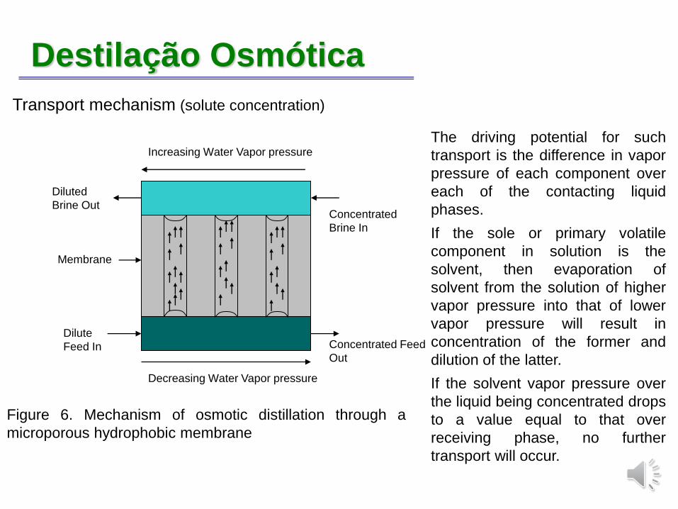
Destilação Osmótica
Transport mechanism (solute concentration)
Figure 6. Mechanism of osmotic distillation through a
microporous hydrophobic membrane
Concentrated
Brine In
Increasing Water Vapor pressure
Decreasing Water Vapor pressure
Dilute
Feed In Concentrated Feed
Out
Membrane
Diluted
Brine Out
The driving potential for such
transport is the difference in vapor
pressure of each component over
each of the contacting liquid
phases.
If the sole or primary volatile
component in solution is the
solvent, then evaporation of
solvent from the solution of higher
vapor pressure into that of lower
vapor pressure will result in
concentration of the former and
dilution of the latter.
If the solvent vapor pressure over
the liquid being concentrated drops
to a value equal to that over
receiving phase, no further
transport will occur.
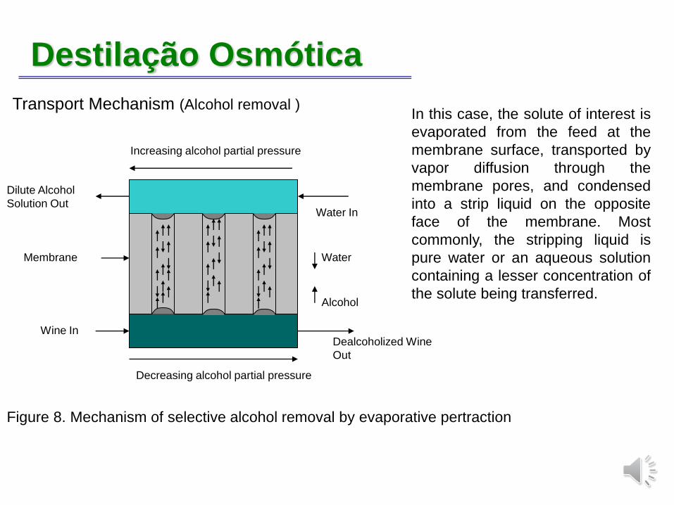
Destilação Osmótica
Transport Mechanism (Alcohol removal )
Figure 8. Mechanism of selective alcohol removal by evaporative pertraction
Water In
Water
Alcohol
Increasing alcohol partial pressure
Decreasing alcohol partial pressure
Wine InDealcoholized Wine
Out
Membrane
Dilute Alcohol
Solution Out
In this case, the solute of interest is
evaporated from the feed at the
membrane surface, transported by
vapor diffusion through the
membrane pores, and condensed
into a strip liquid on the opposite
face of the membrane. Most
commonly, the stripping liquid is
pure water or an aqueous solution
containing a lesser concentration of
the solute being transferred.
Destilação OsmóticaThe most suitable materials for OD membranes are apolar polymers with low surface free
energies. These include the polyolefins, particularly PE and PP, and the perfluorocarbons,
especially PTFE and PVDF. Microporous membranes fabricated from these materials are
available with pore sizes and pore size distributions in acceptable ranges for this application.
The maximum tolerable pore radius to prevent liquid penetration is about 250 nm—
corresponding to a pore diameter of about 0.5 micron. Commercially available microporous
membranes fall well within this range of pore dimensions. Membranes of smaller pore size
than this, of course, will withstand higher hydrostatic pressures without liquid intrusion.
The selection of an osmotic agent for use on an industrial scale should preferably be in
accordance with several basic requirements. It should be thermally stable, nonvolatile, and
have a steep positive temperature coefficient of solubility. These properties allow the diluted
strip solution to be reconcentrated to high levels (through thermal evaporation) for reuse in
the OD process without loss or danger of crystallization in the evaporator. Also, the osmotic
agent should be biocidal, nontoxic, low cost and of food-grade quality.
For the osmotic distillation process, mostly salt solutions (NaCl, CaCl2, K2HPO4, potassium
acetate) or some kind of organic solutions (polyethylene glycol, glycerol, etc.) are used as an
osmotic agent.
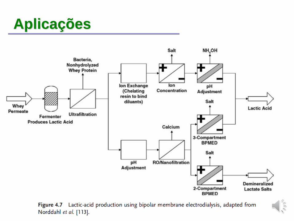
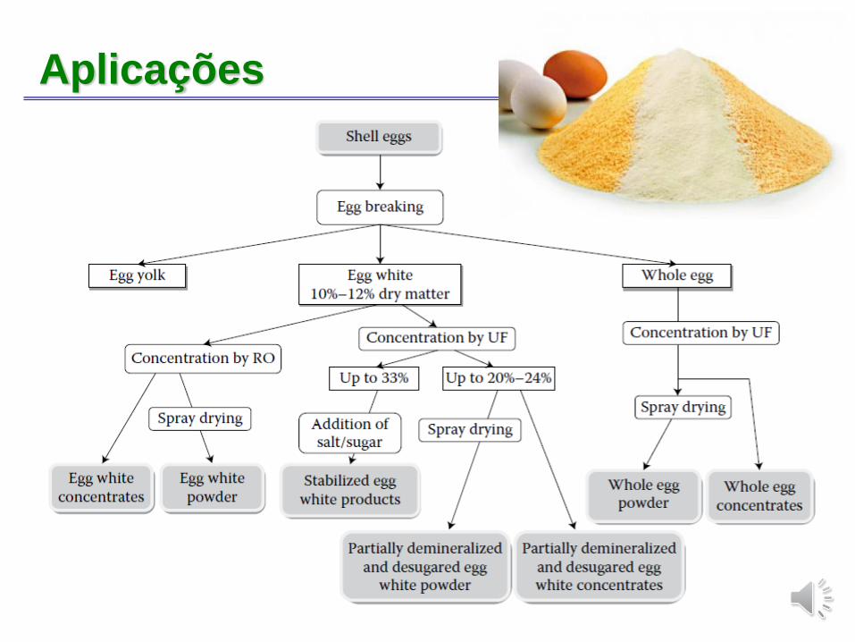
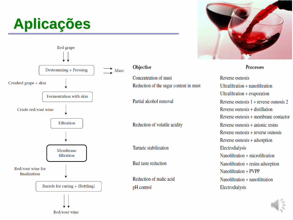
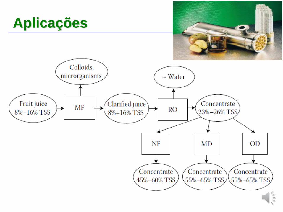
Aplicações
Aplicações
Aplicações
Aplicações
Aplicações
Aplicações
Problemas
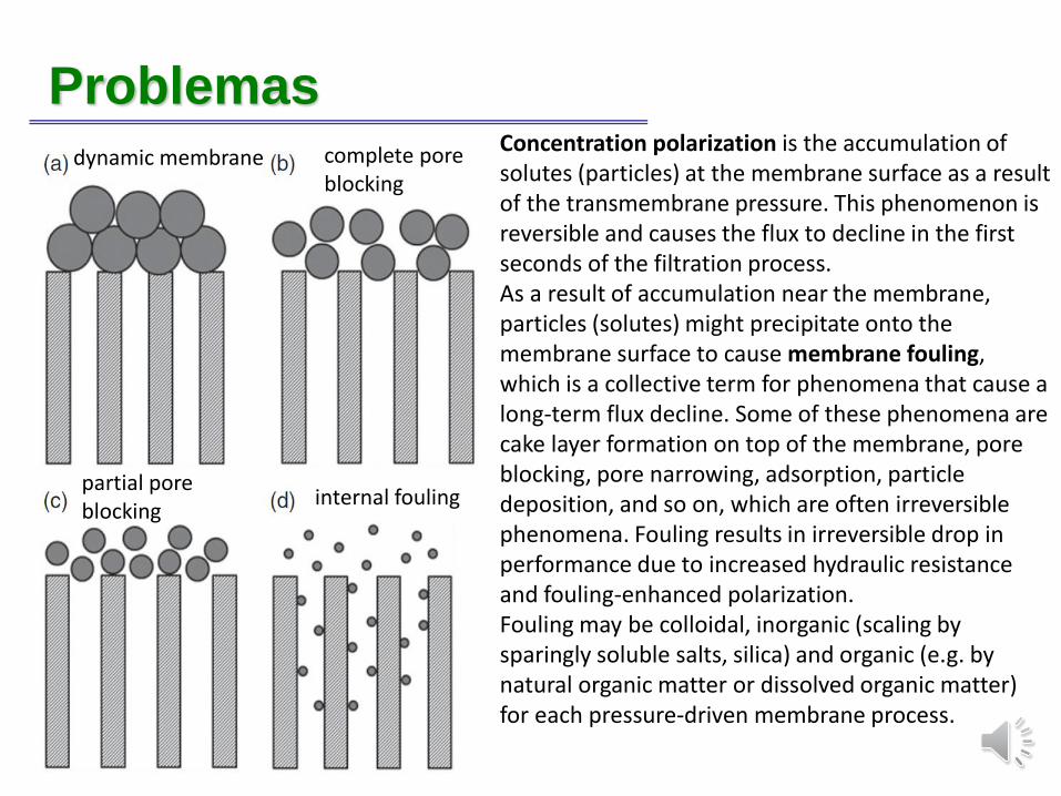
internal fouling
Concentration polarization is the accumulation of solutes (particles) at the membrane surface as a result of the transmembrane pressure. This phenomenon is reversible and causes the flux to decline in the first seconds of the filtration process. As a result of accumulation near the membrane, particles (solutes) might precipitate onto the membrane surface to cause membrane fouling, which is a collective term for phenomena that cause a long-term flux decline. Some of these phenomena are cake layer formation on top of the membrane, pore blocking, pore narrowing, adsorption, particle deposition, and so on, which are often irreversible phenomena. Fouling results in irreversible drop in performance due to increased hydraulic resistance and fouling-enhanced polarization.Fouling may be colloidal, inorganic (scaling by sparingly soluble salts, silica) and organic (e.g. by natural organic matter or dissolved organic matter) for each pressure-driven membrane process.
dynamic membrane complete poreblocking
partial poreblocking
Problemas
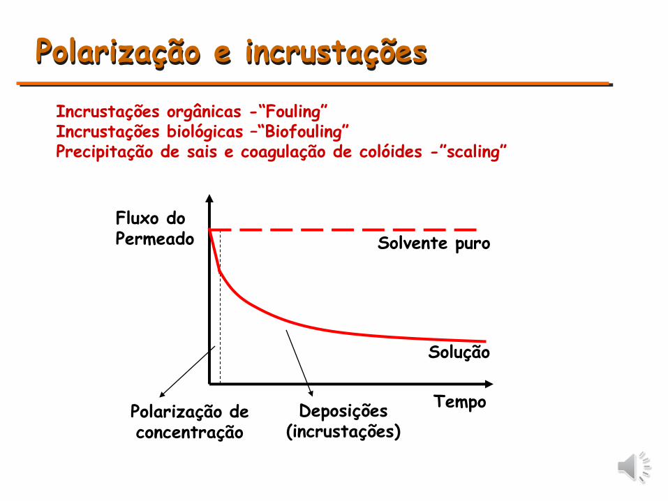
Solvente puro
Solução
Tempo
Fluxo do Permeado
Polarização de concentração
Polarização e incrustações
Incrustações orgânicas -“Fouling”Incrustações biológicas –“Biofouling”Precipitação de sais e coagulação de colóides -”scaling”
Deposições(incrustações)
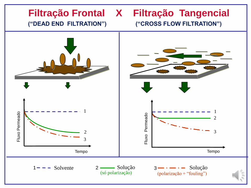
Filtração Frontal X Filtração Tangencial
Solução(polarização + “fouling”)
3Solução (só polarização)
2Solvente1
Flu
xo
Pe
rme
ado
Tempo
1
2
3
Tempo
Flu
xo
P
erm
ea
do 1
2
3
(“DEAD END FILTRATION”) (“CROSS FLOW FILTRATION”)
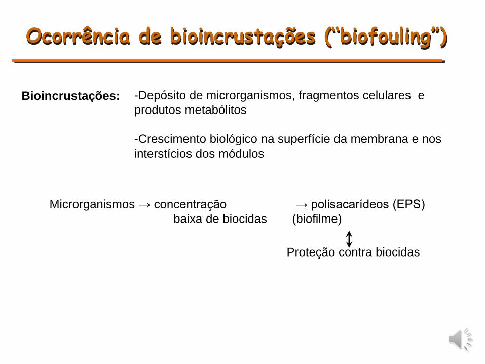
Ocorrência de bioincrustações (“biofouling”)
-Depósito de microrganismos, fragmentos celulares e
produtos metabólitos
-Crescimento biológico na superfície da membrana e nos
interstícios dos módulos
Bioincrustações:
Microrganismos → concentração → polisacarídeos (EPS)
baixa de biocidas (biofilme)
Proteção contra biocidas
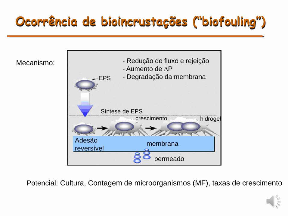
Ocorrência de bioincrustações (“biofouling”)
- Redução do fluxo e rejeição
- Aumento de DP
- Degradação da membranaEPS
membrana
permeado
Adesão
reversível
Síntese de EPS
crescimento hidrogel
Mecanismo:
Potencial: Cultura, Contagem de microorganismos (MF), taxas de crescimento
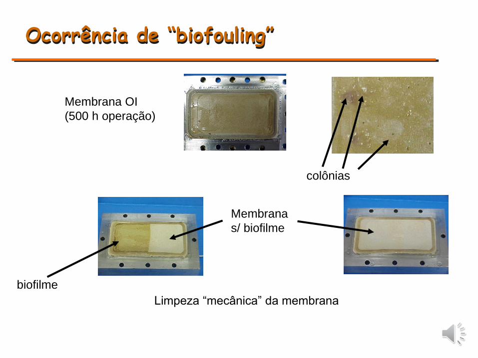
Ocorrência de “biofouling”
Membrana OI
(500 h operação)
colônias
Limpeza “mecânica” da membrana
biofilme
Membrana
s/ biofilme
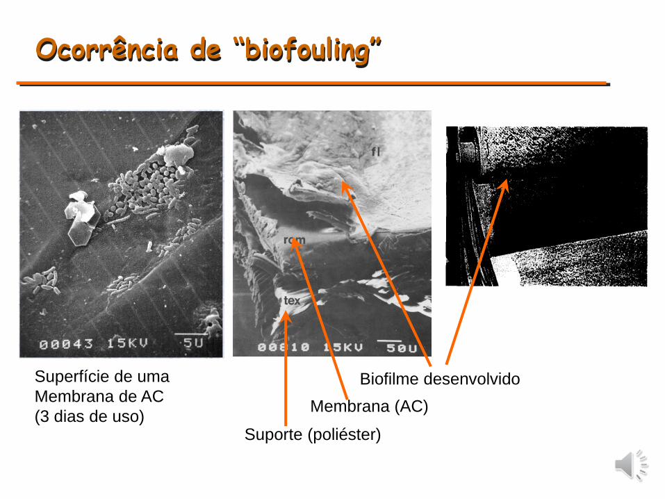
Ocorrência de “biofouling”
Superfície de uma
Membrana de AC
(3 dias de uso)
Biofilme desenvolvido
Membrana (AC)
Suporte (poliéster)
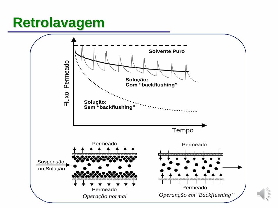
Retrolavagem
Flu
xo
Pe
rme
ad
o
Tempo
Solução:Sem “backflushing”
Solução:Com “backflushing”
Solvente Puro
Suspensão
ou Solução
Permeado
Permeado
Operação normal Operanção em“Backflushing”
Permeado
Permeado
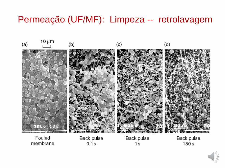
Permeação (UF/MF): Limpeza -- retrolavagem
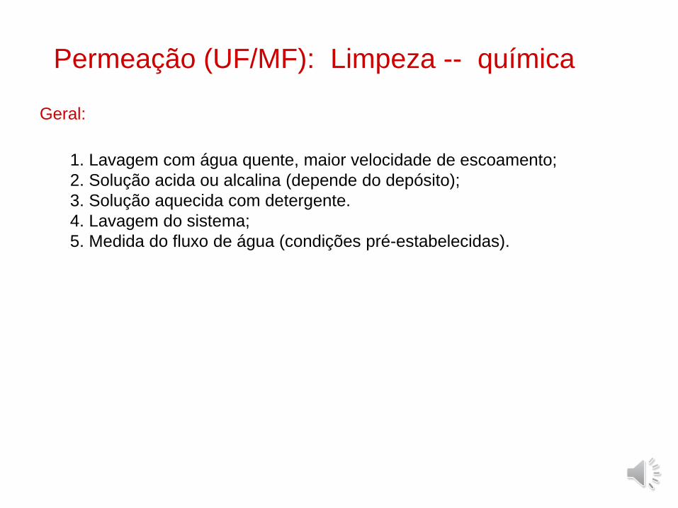
Permeação (UF/MF): Limpeza -- química
1. Lavagem com água quente, maior velocidade de escoamento;
2. Solução acida ou alcalina (depende do depósito);
3. Solução aquecida com detergente.
4. Lavagem do sistema;
5. Medida do fluxo de água (condições pré-estabelecidas).
Geral: