Embed Size (px)
DESCRIPTION
uma antena para espaço reduzidos
Citation preview

REVELANDO A TAK-TENNA (BROWN DIPOLO)PARA 40 E 80 METROSterça-feira, 20 outubro 2009 8:50 PM Ψ
UM CONCEITO CRIADO POR ALAN R. BROWN EM 1969.(ALGUNS ARGUMENTAM QUE SERIA UMA VERSÃO DE UMA ANTENA PESQUISADA PELOINCRÍVEL NICOLAS TESLA) ESQUECIDA E REVITALIZADA AGORA PELOS RADIOAMADORES AMERICANOS E EUROPEUS. TAMBÉM CHAMADA DE
BROWN DIPOLO.
- 1 -

DETALHES:BOOM COM COMPRIMENTO de 76 CENTÍMETROS FEITO DE PVC DE 1 POLEGADA ou 3/4 veja abaixo.
4 PEDAÇOS DE CANO DE PVC DE MEIA COM 66 CENTÍMETROS DE COMPRIMENTOS PARA A CRUZETA. (USE PVC BRANCO)33 CENTÍMETROS PARA CADA LADO(PARA 80 METROS PODE SER USADO 76 A 78 CENTÍMETROS)
O INICIO DO ENROLAMENTO A 8 CENTÍMETROS DO CENTROESPAÇAMENTO ENTRE ESPIRAS 2.5 CENTÍMETROS
TAMBEM ACONSELHA-SE FAZER O BOOM AJUSTÁVEL, OU SEJA USANDO COMO BOOM UM PVC DE 3/4 E SECÇÕES DE 1 POLEGADA PARAAJUSTE(VIDE FOTO) O TAMANHO DO BOM SERIA VARIADO EXPERIMENTALMENTE DE DE 68 A 97 CENTÍMETROS JUNTAMENTE COM A TOMADA FEITA
NAS ESPIRAS VIA GARRAS JACARÉ.
- 2 -
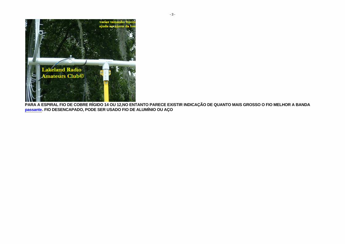
PARA A ESPIRAL FIO DE COBRE RÍGIDO 14 OU 12,NO ENTANTO PARECE EXISTIR INDICAÇÃO DE QUANTO MAIS GROSSO O FIO MELHOR A BANDA passante. FIO DESENCAPADO, PODE SER USADO FIO DE ALUMÍNIO OU AÇO
- 3 -

O COAXIAL DE DESCIDA DEVE SER COLOCADO NO CENTRO DO BOOM E LIGADO ÀS ESPIRAS POR MEIO DE FIOS DE COBRE RÍGIDO ENCAPADO MESMO DIÂMETRO DO USADO NAS ESPIRAIS.
- 4 -

O AJUSTE DA ESTACIONÁRIA É FEITO VARIANDO SIMULTANEAMENTE POR MEIO DE GARRA JACARÉ A LIGAÇÃO DO CABO A PARTIR DO INICIO DASESPIRAS ( COMEÇO DO ENROLAMENTO)ATÉ ENCONTRAR O MELHOR PONTO, QUANDO ENTÃO SERÁ FEITA A FIXAÇÃO POR SOLDA. O AJUSTE DA
ROE DEVE SER FEITO NA FREQUENCIA PARA QUAL A ANTENA FOI CALCULADA .É UM AJUSTE CRÍTICO E DEVE SER FEITO MILÍMETRO A MILÍMETROSE COM MUITA PACIÊNCIA. O PONTO DA MELHOR ROE PODERÁ VARIAR BASTANTE DE UMA ESPIRAL PARA OUTRA. PACIÊNCIA!
AO MESMO TEMPO AUMENTE OU DIMINUA O TAMANHO DO BOOM.PODE SER NECESSÁRIO AJUSTAR O TAMANHO DAS ESPIRAIS, CORTANDO OU AUMENTANDO O TAMANHO DO FIO, MAS SÓ COMO ÚLTIMA
INSTÂNCIA.
- 5 -

- 6 -

A ANTENA PARA AJUSTE DEVE FICAR NO MÍNIMO A 2 METROS E MEIO DO SOLO.RECOMENDA-SE QUE SEJA INSTALADA A PARTIR DE 7 METROS DE ALTURA E ALGUNS UTILIZAM-NA VERTICAL.
EXPERIMENTE.ALGUNS AUTORES RECOMENDAM UM BALUN 1:1 , O QUE ACHAMOS IMPORTANTE.
PARA MASTRO USE UM CANO DE PVC DE 1 METRO E MEIO, INSERINDO O MESMO NO MASTRO METÁLICO.
O COMPRIMENTO DAS DUAS ESPIRAIS SEGUE A FÓRMULA139.5/f EM Mhz + 3 POR CENTO
APÓS DIVIDA POR 2 PARA OBTER O COMPRIMENTO PARA CADA LADO DA ANTENAPARA O CABO COAXIAL USE A FÓRMULA 99/f EM Mhz(A MESMA FREQUÊNCIA UTILIZADA NO CÁLCULO ANTERIOR) USANDO, SE NECESSÁRIO,
MÚLTIPLOS INTEIROS DO VALOR OBTIDO. CABO DE 50 OHMS.EXISTEM EXPERIÊNCIAS DESTA ANTENA PARA 80, 40, 20 E 15 , 12, 10 E 11 METROS.
EMBORA AO QUE PAREÇA O MELHOR DESEMPENHO SEJA EM 80 E 40 METROS E 20M. O PROBLEMA TAMANHO DE ANTENA JÁ NÃO É TÃO CRÍTICO APARTIR DE 12 METROS,PELA FACILIDADE DE SE USAR ANTENAS VERTICAIS.
OBSERVE AS FOTOS QUE PRATICAMENTE INDICAM O MEIO DE FAZER.
- 7 -

- 8 -

COMEÇE O ENROLAMENTO DE DENTRO PRA FORA, EMBORA ALGUNS AUTORES RECOMENDEM COMEÇAR DE FORA PARA DENTRO, FAÇA A SUAOPÇÃO.
OBSERVE QUE UMA DAS ESPIRAIS COMEÇA A SER ENROLADA DA DIREITA PRA ESQUERDA E A OUTRA DA ESQUERDA PARA A DIREITA.NORMALMENTE COM AS MEDIDAS DADAS A ANTENA DE 80 METROS TEM 16 ESPIRAS E A DE 40 METROS 12 ESPIRAS,
EMBORA PARA A FREQUENCIA PARA ONDE FOI PLANEJADA A ANTENA NÃO PRECISE, PODE SER USADO ACOPLADOR ;ASSIM A MESMA PODE SER
- 9 -
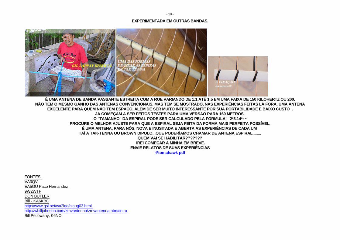
EXPERIMENTADA EM OUTRAS BANDAS.
É UMA ANTENA DE BANDA PASSANTE ESTREITA COM A ROE VARIANDO DE 1:1 ATÉ 1:5 EM UMA FAIXA DE 150 KILOHERTZ OU 200.NÃO TEM O MESMO GANHO DAS ANTENAS CONVENCIONAIS, MAS TEM SE MOSTRADO, NAS EXPERIÊNCIAS FEITAS LÁ FORA, UMA ANTENA
EXCELENTE PARA QUEM NÃO TEM ESPAÇO, ALÉM DE SER MUITO INTERESSANTE POR SUA PORTABILIDADE E BAIXO CUSTO .JA COMEÇAM A SER FEITOS TESTES PARA UMA VERSÃO PARA 160 METROS.
O "TAMANHO" DA ESPIRAL PODE SER CALCULADO PELA FÓRMULA: 2*3.14*r ~PROCURE O MELHOR AJUSTE PARA QUE A ESPIRAL SEJA FEITA DA FORMA MAIS PERFEITA POSSÍVEL.
É UMA ANTENA, PARA NÓS, NOVA E INUSITADA E ABERTA AS EXPERIÊNCIAS DE CADA UM TAÍ A TAK-TENNA OU BROWN DIPOLO...QUE PODERÍAMOS CHAMAR DE ANTENA ESPIRAL........
QUEM VAI SE HABILITAR??????? IREI COMEÇAR A MINHA EM BREVE.
ENVIE RELATOS DE SUAS EXPERIÊNCIASΨ tomahawk pdf
FONTES:VA3QVEA5GU Paco Hernandez 9W2WTFDON BUTLERBill - KA6KBChttp://www.qsl.net/wa2lqo/nlaug03.html http://wbilljohnson.com/zmvantenna/zmvantenna.htm#introBill Petlowany, K6NO
- 10 -

Steve – WA2TAK http://www.tak-tenna.com/http://bvarc.freeshell.org/newsletter/BVARC_December_2007.pdfKL7JRGIL LAPPAY KF2KWTEA5AMMYI1FLY
COLABORAÇÃO DEΨ DINEY TARUGO SCAFURA WILLEMENΨPU1PBYPX1K6886SWLPY10130RADIO ATIVISTAOPERADOR GERAL GMDSSRADIO TELEFONISTA GERAL
http://ferrodesoldar.nireblog.com
http://radiotelefonista.nireblog.com
http://dineymonteiro.nireblog.com
FORTE 73!
- 11 -


Project Overview - Bill's- Pan Cake - 40 Meter TAK-tenna or tak tenna... http://www.myhamshack.com/viewProject.aspx?ProjectID=23
1 de 1 20/9/2009 00:48
Search MyHamShack
Go
Help keep MyHamShack Free with a donation.
Home Ham Shacks Blogs Classifieds Projects About Contact Register Log In
PROJECT
Bill's- Pan Cake - 40 Meter TAK-tenna or tak tenna or Tak Antenna
from KA6KBC
Project Overview
Homebrew: Tak-tenna or Tak Antenna
SEE a MUCH better Write up:
http://billbrwn.tripod.com//id3.html
So I've been reading about this Small Space antenna that is being sold as the TAK-Tenna.
Really neat idea - Has a 30" boom and Sprial Coils on the ends. See a picture athttp://www.taktenna.com/
Looks easy to built - Right !
So I Built my version out of wood - Mine is very ugly as compared to the store bought one.
Well it does load up with a respectible SWR 1:1 to 1:5 from 7.300 to 7.175 MHZ (No Transmatch).
My dipole does better, but the antenna works and is really small.
Materials and Tools
Parts:
3 - Wooden sections - 1 1/2" X 1/2 " X 8' - Cost 92 Cent each - Home Depot
1 - Spool of Steel Guide/fence Wire - Cost - $7 - Home Depot
1 - 25 foot RG8 coax with PL259 - Radio Shack - Close Out - $5
2 Packages - Nuts/Bolts - $2 - Home Depot
2 - Aligator Chips - Junk Box.
Total Material Cost: $16.76
The commerical version uses PVC, which would have been much easyier.
Tools: Need just basic hand Tools - Hand Saw, Drill, and Wire Cutters.
Go to: Overview 1 2 3 4 5Next Step >>
Copyright © 2009 My Ham Shack All Rights Reserved | Privacy Policy | Terms of Use | By OrbStone Technology
Overview 1 2 3
4 5
RF Band pass Filters
Ceramic,Diplexers,Duplexers,Cavity Crystal,LC,Lowpass,Highpass,SAW www.www.anatechelectronics.com
KG-UVD1P Dual
Band Radio
Wouxun Dual Band handheld radio 136-174 and 400-470 Mhz www.radiogearpro.com
UHF Panel Antennas
UHF Directional Panel Antennas 8 dB gain. Get Info! www.dbSpectra.com
TOC Radio
Remoting
Install antennas without coax Move antennas 10-km from CP www.SyntonicsCorp.com
Comfy Clamps from
WebbAfrica's top selling RF cable clamp Now available in Europe www.multiband.eu

Project Page 1 - Bill's- Pan Cake - 40 Meter TAK-tenna or tak tenna or... http://www.myhamshack.com/viewProject.aspx?ProjectID=23&Page...
1 de 2 20/9/2009 00:47
Search MyHamShack
Go
Help keep MyHamShack Free with a donation.
Home Ham Shacks Blogs Classifieds Projects About Contact Register Log In
PROJECT
Bill's- Pan Cake - 40 Meter TAK-tenna or tak tenna or Tak Antenna
from KA6KBC
Step
1
See a picture of the
commerical version of the Antenna (http://www.tak-tenna.com/) - Mine is all wood and does not look that clean.
However - Test wise it isn't bad I got it tuned up on 40 meters at about 8 feet off the ground and it has an SWR 1:2 to 1:5 from 7.30 to 7.175 MHZ (No Transmatch).
Bad news the performance is not Great - Signal pick up is several S units below my Dipole, but it does work.
From what I have read the Antenna has problems in that most of the performance is based on feedline radiation.
http://lists.contesting.com/archives//html/Towertalk/2008-04/msg00339.html
Overview 1 2 3
4 5

Project Page 1 - Bill's- Pan Cake - 40 Meter TAK-tenna or tak tenna or... http://www.myhamshack.com/viewProject.aspx?ProjectID=23&Page...
2 de 2 20/9/2009 00:47
Go to: Overview 1 2 3 4 5Next Step >>
Copyright © 2009 My Ham Shack All Rights Reserved | Privacy Policy | Terms of Use | By OrbStone Technology

Project Page 2 - Bill's- Pan Cake - 40 Meter TAK-tenna or tak tenna or... http://www.myhamshack.com/viewProject.aspx?ProjectID=23&Page...
1 de 2 20/9/2009 00:46
Search MyHamShack
Go
Help keep MyHamShack Free with a donation.
Home Ham Shacks Blogs Classifieds Projects About Contact Register Log In
PROJECT
Bill's- Pan Cake - 40 Meter TAK-tenna or tak tenna or Tak Antenna
from KA6KBC
Step
2
My dipole does better (by
several S Units), but the antenna works and is really small.
Again - However - Upon doing some research you will find that many say that most of the radiated power is coming fromthe feedline.
http://lists.contesting.com/archives//html/Towertalk/2008-04/msg00339.html
Overview 1 2 3
4 5

Project Page 2 - Bill's- Pan Cake - 40 Meter TAK-tenna or tak tenna or... http://www.myhamshack.com/viewProject.aspx?ProjectID=23&Page...
2 de 2 20/9/2009 00:46
Go to: Overview 1 2 3 4 5Next Step >>
Copyright © 2009 My Ham Shack All Rights Reserved | Privacy Policy | Terms of Use | By OrbStone Technology

Project Page 3 - Bill's- Pan Cake - 40 Meter TAK-tenna or tak tenna or... http://www.myhamshack.com/viewProject.aspx?ProjectID=23&Page...
1 de 2 20/9/2009 00:45
Search MyHamShack
Go
Help keep MyHamShack Free with a donation.
Home Ham Shacks Blogs Classifieds Projects About Contact Register Log In
PROJECT
Bill's- Pan Cake - 40 Meter TAK-tenna or tak tenna or Tak Antenna
from KA6KBC
Step 3
For Tuning- Use
Aligator Clips connect to the Coax and clip to Coils. I would suggest - Working outfrom the smallest part of the Coil then out in Even steps. I was able to get minematched - In about 3 Trips.
Overview 1 2 3
4 5
TDK Horn Antenna
1-18GHz
Wide band,
double-ridged horn
High gain, low VSWR,
robust design www.tdkrfsolutions.com
Mobile Com.
Equipment
Wired and wireless
integration System
Development &
Distribution www.Soluwins.biz
UHF Panel Antennas
UHF Directional Panel Antennas 8 dB gain.
Get Info! www.dbSpectra.com
RF/Microwave
online
RF & Microwave
filters, amplifiers couplers,terminations,antennas www.www.amcrf.com
KG-UVD1P Dual
Band Radio
Wouxun Dual Band
handheld radio
136-174 and 400-470
Mhz www.radiogearpro.com

Project Page 3 - Bill's- Pan Cake - 40 Meter TAK-tenna or tak tenna or... http://www.myhamshack.com/viewProject.aspx?ProjectID=23&Page...
2 de 2 20/9/2009 00:45
Go to: Overview 1 2 3 4 5Next Step >>
Copyright © 2009 My Ham Shack All Rights Reserved | Privacy Policy | Terms of Use | By OrbStone Technology

Project Page 4 - Bill's- Pan Cake - 40 Meter TAK-tenna or tak tenna or... http://www.myhamshack.com/viewProject.aspx?ProjectID=23&Page...
1 de 1 20/9/2009 00:45
Search MyHamShack
Go
Help keep MyHamShack Free with a donation.
Home Ham Shacks Blogs Classifieds Projects About Contact Register Log In
PROJECT
Bill's- Pan Cake - 40 Meter TAK-tenna or tak tenna or Tak Antenna
from KA6KBC
Step 4
One more added item -
Someone had a question about my dimensions:
Boom = 30 inches meaning Cross Pieces are about 30 inches a part.
Cross Pieces = 24 Inches Across or 12 Inches from center
Hole Spacing from Center, but this did not seem critical:
12 in
11 in
10 in
9 in
8 in
7 in
6 in
5 in
4 in
3 in
Total Turns = 10
If you make your own one point - I needed more wire than the 468/7.2 MHZ = 65 Feet Total or 32.5 Feet per side - I had to add wire after the fact. So I would make it about 33.5 per side.
The spacing did not seem critical, but Read my related Links Section.
73's
Bill - KA6KBC
Go to: Overview 1 2 3 4 5Next Step >>
Copyright © 2009 My Ham Shack All Rights Reserved | Privacy Policy | Terms of Use | By OrbStone Technology
Overview 1 2 3
4 5
Antennas for
OrbcommLow Profile, Small
Footprint Combination
antennas for
Orbcomm www.multiband-antennas.com
TDK Horn Antenna
1-18GHz
Wide band,
double-ridged horn
High gain, low VSWR,
robust design www.tdkrfsolutions.com
UHF Panel Antennas
UHF Directional Panel Antennas 8 dB gain.
Get Info! www.dbSpectra.com
Mobile Com.
Equipment
Wired and wireless
integration System
Development &
Distribution www.Soluwins.biz
Burda ShortWave
Heaters
Effective, targeted
and instant IR
Heating. Get more
info here! www.Burdawtg.com/ShortWave_Heat

http://www.instructables.com/id/Spooky-Tesla-Spirit-Radio/
Spooky Tesla Spirit Radioby mrfixits on July 16, 2009
Table of Contents
intro: Spooky Tesla Spirit Radio . . . . . . . . . . . . . . . . . . . . . . . . . . . . . . . . . . . . . . . . . . . . . . . . . . . . . . . . . . . . . . . . . . . . . . . . . . . . . . . . . . . . . . . . . . . . . . . . . . 2
step 1: Parts List And Schematic Diagram . . . . . . . . . . . . . . . . . . . . . . . . . . . . . . . . . . . . . . . . . . . . . . . . . . . . . . . . . . . . . . . . . . . . . . . . . . . . . . . . . . . . . . . . . . 3
step 2: Make a Clear Cover and Drill It . . . . . . . . . . . . . . . . . . . . . . . . . . . . . . . . . . . . . . . . . . . . . . . . . . . . . . . . . . . . . . . . . . . . . . . . . . . . . . . . . . . . . . . . . . . . . 4
step 3: Mount the Components on the Cover . . . . . . . . . . . . . . . . . . . . . . . . . . . . . . . . . . . . . . . . . . . . . . . . . . . . . . . . . . . . . . . . . . . . . . . . . . . . . . . . . . . . . . . . 6
step 4: Prepare the Induction Coil . . . . . . . . . . . . . . . . . . . . . . . . . . . . . . . . . . . . . . . . . . . . . . . . . . . . . . . . . . . . . . . . . . . . . . . . . . . . . . . . . . . . . . . . . . . . . . . . 7
step 5: Wiring and Soldering . . . . . . . . . . . . . . . . . . . . . . . . . . . . . . . . . . . . . . . . . . . . . . . . . . . . . . . . . . . . . . . . . . . . . . . . . . . . . . . . . . . . . . . . . . . . . . . . . . . . 7
step 6: Make the Tesla Spiral Antennas . . . . . . . . . . . . . . . . . . . . . . . . . . . . . . . . . . . . . . . . . . . . . . . . . . . . . . . . . . . . . . . . . . . . . . . . . . . . . . . . . . . . . . . . . . . . 8
step 7: Make a Peculiar Tesla Football Antenna . . . . . . . . . . . . . . . . . . . . . . . . . . . . . . . . . . . . . . . . . . . . . . . . . . . . . . . . . . . . . . . . . . . . . . . . . . . . . . . . . . . . . . 10
step 8: Testing the AM Radio Circuit . . . . . . . . . . . . . . . . . . . . . . . . . . . . . . . . . . . . . . . . . . . . . . . . . . . . . . . . . . . . . . . . . . . . . . . . . . . . . . . . . . . . . . . . . . . . . . 14
step 9: Spooky Effect # 1 - Disembodied Spirit Voices . . . . . . . . . . . . . . . . . . . . . . . . . . . . . . . . . . . . . . . . . . . . . . . . . . . . . . . . . . . . . . . . . . . . . . . . . . . . . . . . . 14
step 10: Spooky Effect # 2 - Detect Lightning and Predict Storms . . . . . . . . . . . . . . . . . . . . . . . . . . . . . . . . . . . . . . . . . . . . . . . . . . . . . . . . . . . . . . . . . . . . . . . . . 15
step 11: Spooky Effect # 3 - Make Lights Sound Weird . . . . . . . . . . . . . . . . . . . . . . . . . . . . . . . . . . . . . . . . . . . . . . . . . . . . . . . . . . . . . . . . . . . . . . . . . . . . . . . . . 15
step 12: Spooky Effect # 4 - Make Freaky Music . . . . . . . . . . . . . . . . . . . . . . . . . . . . . . . . . . . . . . . . . . . . . . . . . . . . . . . . . . . . . . . . . . . . . . . . . . . . . . . . . . . . . . 16
step 13: Spooky Effect #5 - Van Eck Phreaking . . . . . . . . . . . . . . . . . . . . . . . . . . . . . . . . . . . . . . . . . . . . . . . . . . . . . . . . . . . . . . . . . . . . . . . . . . . . . . . . . . . . . . 17
step 14: Spooky Effect #6 - Make Fright With A Mike . . . . . . . . . . . . . . . . . . . . . . . . . . . . . . . . . . . . . . . . . . . . . . . . . . . . . . . . . . . . . . . . . . . . . . . . . . . . . . . . . . 18
step 15: Spooky Effect # 7 - There's A Woodpecker In Your Modem! . . . . . . . . . . . . . . . . . . . . . . . . . . . . . . . . . . . . . . . . . . . . . . . . . . . . . . . . . . . . . . . . . . . . . . 18
Advertisements . . . . . . . . . . . . . . . . . . . . . . . . . . . . . . . . . . . . . . . . . . . . . . . . . . . . . . . . . . . . . . . . . . . . . . . . . . . . . . . . . . . . . . . . . . . . . . . . . . . . . . . . . . . . . . . 19

http://www.instructables.com/id/Spooky-Tesla-Spirit-Radio/
intro: Spooky Tesla Spirit Radio"My first observations positively terrified me as there was present in them something mysterious, not to say supernatural, and I was alone in my laboratory at night"- Nikola Tesla 1901
Nikola Tesla has been recognized as the inventor of the radio since 1943. This Spooky Tesla Spirit Radio is a tribute to that little-known fact. The simple crystal radiocircuit in it makes spooky sounds by responding to input from several sources. It is non-powered, so no batteries are required!
This radio's basic L-C (Inductor-Capacitor) circuit would be similar to what Tesla would have experimented in his early days. The germanium diode substitutes for thenickel detectors and sensitive relays used by Tesla.
Although it can receive AM broadcasts, this radio was made to have fun with in other ways. AM radio wasn't exactly what Nikola Tesla was interested in...in fact, hebelieved it was a waste of energy to transmit and receive Hertzian waves!
"You must not make the antenna give off 90 percent in electromagnetic and 10 percent in current waves, because the electromagnetic waves are lost by the time you area few arcs around the planet, while the current travels to the uttermost distance of the globe and can be recovered." ...Nikola Tesla
The Spooky Tesla Spirit Radio is housed in a jam jar with a see-through polycarbonate lid. It connects to the computer sound-in jack with a patch cord. By using aprogram like Audio Hyjack Pro (Mac), the output can be tweaked to give some great real-time sound effects...and record them at the same time!
In the accompanying movie, I show how the Spooky Tesla Spirit Radio reacts to many frequencies of light, sound, vibration, radio frequencies, RF pulses, magnetic fieldsand more. For best AM radio reception, it can be hooked up to a longer antenna and a ground connection for greater sensitivity and better sound.
The plug-in antennas I made, are similar in shape to what Tesla designed for his energy transmission and receiving systems as in patent # 723188. Another optionalantenna I experimented with, is the mysterious football-shaped coil that Tesla incorporated into later high voltage experiments.

http://www.instructables.com/id/Spooky-Tesla-Spirit-Radio/
step 1: Parts List And Schematic DiagramList of Materials
1- Small Jam Jar, (Mason Jar) with large mouth1- 3 1/4 inch dia Plexiglas (or polycarbonate) cover lid1- C1 - 60/160 pf Variable Capacitor1- Extension Shaft and Knob for above1- L1 - Ferrite Loopstick Antenna (I1)1- D1 - Germanium 1N34A Diode (*Allied Stock#: 935-0301) $2.16 ea1- C2 - .001uf Capacitor (marked 102) (*Allied Stock#: 507-0822) $.21 ea1- R1 - 47k Resistor (*Allied Stock#: 296-6641) $.05 ea1- Chassis Banana Jack Red - (*Allied Stock#: 528-0158) $.53 ea1- Chassis Banana Jack Black - (*Allied Stock#: 528-0159) $.53 ea2 - (or more for each antenna) Banana Plug (*Allied Stock#: 528-0302) $1.212 -3.5 mm Mono Chassis Jack (*Allied Stock#: 932-0260) $1.16a few inches of 20 gauge hook-up wiresolder1- Audio Patch Cord, 1/8 inch plug ends
Optional - A second audio cord for a Hand Grip and Aux In
Note: For Each Spiral Pancake Antenna,6 feet of #14 gauge solid copper wireBanana Plug
Note: For the Football Style Antenna,4 feet #10 gauge solid copper wire.40 feet of #30 gauge coated magnet wire.Heavy PaperScotch TapeHot GlueSuperGlueBanana Plug
ToolsNeedlenose pliersWire CutterSoldering ironComputer w/ Audio Hijack audio software (Mac), or equivalent
Crystal radio parts and kits available at http://comtrolauto.com/

http://www.instructables.com/id/Spooky-Tesla-Spirit-Radio/
step 2: Make a Clear Cover and Drill ItThe first step is to create a clear lid so we can see the simple but effective radio components. I chose polycarbonate just because that is what I had on hand. I used acircle cutting attachment on a drill press to cut out a 3.25 inch disc out of 3/16 inch Lexan polycarbonate.
Next, 1/4 inch holes are drilled in the clear cover lid for the two banana jacks and for the two audio jacks.
The two banana jacks will receive banana plugs with pre-mounted antennas. Two audio jacks will also be used. One is for for audio out to the computer, and one is forauxiliary input modulation from a hand gripper or other source.
Drill holes as seen in the photos, or lay out your own hole design. I drilled a total of nine holes;Two 1/4 inch holes for antenna banana jacks,Two 1/4 inch holes for audio jacks,One hole for the variable capacitor shaft, and two small 1/16th inch holes for its screwsand two 1/16th inch holes to feed the diode wires to mount the diode on top of the jar lid (This is for better light-to-sound effects; as the 1N34A diode is light-sensitive)

http://www.instructables.com/id/Spooky-Tesla-Spirit-Radio/

http://www.instructables.com/id/Spooky-Tesla-Spirit-Radio/
step 3: Mount the Components on the CoverMount the Adjustable Capacitor and Banana Jacks in the clear jam jar cover.
For the variable capacitor, I had to find two screws long enough to feed through the 3/16 inch thick cover. A thinner cover will work with standard screws. The variable caphas an optional shaft extension and knob kit found at http://comtrolauto.com/
Mount the 1/8 phono jacks as well. I had to countersink the holes to get the threads to start because of the rather thick plastic cover I used.
Image Notes1. Countersunk hole and tiny wee screws.2. 60/160 pf Variable capacitor3. Ground terminal4. 160 pf terminal of capacitor5. Not-used terminal. (can be bridged with 160 pf terminal to give 220 pf)6. Banana Jack for Antenna Mount7. 1/4 inch hole for 2nd Banana Jack.
Image Notes1. Common ground connection.2. Diode connection to outside of jar lid through tiny holes. This puts the 1N34Adiode outside the jar.3. 1/8 inch plug Audio Patch Cord goes to "Audio In" jack on computer.4. Auxillary signal input jack5. Banana Jack with antenna plugged in with its banana plug attached.6. Banana Jack and antenna plugged in.7. .002 pf capacitor8. 47k ohm resistor9. Diode is about there somewhere!10. 1/8 audio jack11. variable capacitor12. Inductor Coil for AM radio freq. (note negative end has black paint on thecotton wire cover.) available from http://comtrolauto.com/13. Flat Spiral Antenna similar to Tesla design.

http://www.instructables.com/id/Spooky-Tesla-Spirit-Radio/
step 4: Prepare the Induction CoilThere is an option with the Induction coil to run it direct with an antenna connection, or to wrap the Induction Coil with about 10 wraps of 22 gauge wire that runs from theantenna to ground. The first method gives a better chance of a station signal being loud enough with a short antenna. The second wrapped inductor method is best forusing a long (20 foot plus) antenna. See schematic for clarification.
I like the inductive method even with a short antenna, because it gives a clearer signal with less 60 cycle hum. The amplitude of sound will be less in AM tuning unless along antenna is used however. The amplitude can be partially made up by using the human body as an antenna by touching the jam jar ring, which has a connecting wirethat goes to the antenna + wire when the lid is twisted on.
The other advantage of wrapping the inductor is that it gets supported inside the jar by the heavier wires.
Image Notes1. 10 wraps of 22 ga copper magnet wire. Be sure ends are scraped or sanded to remove coating before soldering. (note pre-tinned wire tips)2. ferrite core3. 75 turn coil of very fine wire.4. Tiny wee wires.
step 5: Wiring and SolderingOk, once most components are in place, it's time to wire and solder things up. Direct point-to-point wiring can be used with so few components. Follow the pictures andthe schematic for the basic connections.
Only a couple of wires need to be soldered in. Run one ground wire from the middle ground post of C1 to the ground connection on the phone jack. Another wire will gofrom the antenna to the other C1 post.
Note that the centre connection of the C1 variable capacitor is connected to the ground connection of the phone jack. The 160 pf connection is on the right facing C1 fromthe top looking down, connecting tabs facing away from you. The 60 pf connection is on the other side of the middle ground connection, and was not used.
The D1 diode is heat sensitive and may fail if over-soldered. Use an alligator clip as a heat sink when soldering its leads. I mounted it on top of the cover to make it moresensitive to light.
The L1 Induction Coil thin wire with black paint goes to ground. The other thin inductor wire goes to the non-ground C1 capacitor connection. L2 is simply 10 wraps ofwire around the inductor coil.

http://www.instructables.com/id/Spooky-Tesla-Spirit-Radio/
step 6: Make the Tesla Spiral Antennas"The Tesla antenna is a form of wireless antenna or wave launching structure developed by Nikola Tesla in which the transmitted energy propagates or is carried to thereceiver by a combination of electrical current flowing through the earth, electrostatic induction and electrical conduction through plasma with an embedded magneticfield."- Gary L Peterson in "Rediscovering The Zenneck Surface Wave"
This is an area for scientific and artistic license. There is still much debate as to what exactly Tesla was up to with his transmission and reception of power systems. ( SeeJoel Young's blog comments in Design News Magazine on July 8th, 16th and 28th...http://www.designnews.com/blog/The_Weird_and_Wonderful_World_of_Wireless/index.php?text=tesla+antenna+
I experimented with two types of Tesla antenna design. The first is similar to the flat spiral "Pancake" coil that is seen in several of Tesla's patents. The second is apeculiar "Football" coil made of two cones.
For the basic spiral antenna, I used a 6 foot length of 14 gauge solid copper wire, and bent the wires by hand, coil by coil. I used a needle nose pliers to begin the corespiral, and after a turn or two, gently but firmly worked the wire around with bare hands. I soldered on a short vertical antenna to the centre loop. In retrospect, It wouldhave been better to make the vertical end part with a one piece construction.
Keep working the wire to eliminate kinks and bends, then make sure the coils are evenly spaced. I soldered on the vertical antenna last.

http://www.instructables.com/id/Spooky-Tesla-Spirit-Radio/

http://www.instructables.com/id/Spooky-Tesla-Spirit-Radio/
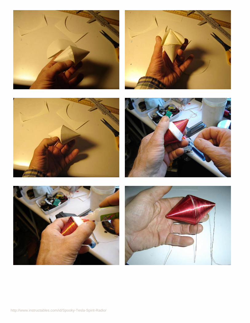
step 7: Make a Peculiar Tesla Football AntennaThis coil was one of Tesla's later designs, and is said to have spooky anti-gravity effects when pumped with the correct frequencies and voltages. I won't be working inthat high-power range with this un-powered crystal radio !
The core of the Tesla Football Antenna is made with four 2 inch paper cones glued and taped together. The paper cones were doubled up, two on each side, for strengthand smoothness.
The 30 gauge wire conical coils are wound laboriously by hand. The thick 10 gage copper wire was carefully bent to conform to the football coil without disturbing thecoils of the coil. (Note to self...don't try this again without coating the wires with a resin or glue first, because the coils will start unravelling...)
After this small coil-winding feat, two snazzy Banana Plug ends are put on. These ones were found at an electronics store.
Here's a link to a similar coil that puts out sparks![http://www.tesla-coil-builder.com/double_cone_bipolar_tesla_coil.htm]

http://www.instructables.com/id/Spooky-Tesla-Spirit-Radio/
http://www.instructables.com/id/Spooky-Tesla-Spirit-Radio/

http://www.instructables.com/id/Spooky-Tesla-Spirit-Radio/

http://www.instructables.com/id/Spooky-Tesla-Spirit-Radio/
step 8: Testing the AM Radio CircuitThis step is a circuit test of the Tesla Spirit Radio, to see if it works as an ordinary AM radio. Once the wiring and solder connections are double checked, we can test theAM radio part of the device.
Plug in the Audio Patch Cord into the 1/8 inch jack of the radio, and then into the computer "Sound In" port. Launch Audio Hijack (or equivalent PC software). Set up witha basic 10-Band EQ and two or three AU Pitch controls. AU Bandpass and Reverb won't be used for this test...use their "Bypass" buttons. Gain may need to be turned uphigh. Au Pitch controls at the neutral 0 pitch setting. (See screenshot below.)
Turn the variable capacitor knob and the sounds of a local AM station should come through; if not, a long antenna may be required in your area. Try touching the jar ringor antenna to see if that makes a difference.
If you have no sound at all, then something is likely wrong. Check for a dry solder connection. Also, if too much soldering heat was used close to or on the diodeconnection, the diode may be burned out. Substitute to check, or use the diode checker function of your multi-meter to test it if necessary.
step 9: Spooky Effect # 1 - Disembodied Spirit Voices""The sounds I am listening to every night at first appear to be human voices conversing back and forth in a language I cannot understand. I find it difficult to imagine thatI am actually hearing real voices from people not of this planet. There must be a more simple explanation that has so far eluded me."-Nikola Tesla 1918
Nikola Tesla, and many others of the early radio pioneers, often thought they heard voices in their radio receptions. Both Edison and Tesla claimed to be working towardscommunicating with disembodied spirits.
Dale Afrey, in the book "The Lost Journals Of Nikola Tesla", says . "At one point Tesla chided Edison for stealing his idea on using a form of radio to contact the dead."
You can get the impression of disembodied spirit voices by tuning close to an AM station, then use the Au Pitch Controls to raise the pitch to a squeaky high, ghostlysound. Add Reverb for the final touch. Au Bandpass is also used in this effect. Check the settings in the screenshot below.
Alternately, the AU Pitch can be used to lower the pitch instead of raising it, for a moaning type effect.

http://www.instructables.com/id/Spooky-Tesla-Spirit-Radio/
step 10: Spooky Effect # 2 - Detect Lightning and Predict Storms"No doubt whatever remained: I was observing stationary waves."Nikola Tesla, commenting on reception of lightning in his receivers.
The Spooky Tesla Spirit Radio can detect lightning!
You can listen to AM radio if you really need to, but Nikola Tesla spent most of his radio listening time tuning into natural Earth (and beyond Earth) pulses, and the highand low frequency vibrations that were around him. He was a storm-chaser from the comfort of his own laboratory.
During Tesla's Colorado Springs experiments, he would listen in on approaching and receding lightning storms, which he could detect up to hundreds of miles away. Henoticed standing waves produced by the lightning that inspired him to develop his wireless power apparatus.
It helps to have a long antenna (be sure it is safely grounded with a spark-gap arrester!), but even with the short antenna, this crystal radio can be made very sensitivewith the computer software adjustments. When a storm is near, you can really hear it! (It's a loud crashing sound in the audio ;)
Requirements: Mac computer and Audio Hijack software. "Super-Sensitive Lightning" software setting adjustment, as seen in the screenshot below...and a nearby storm!PC owners will need to use an audio software solution that is able to alter pitch, gain and reverb in real time. And preferably record it.
Here's a fun site devoted to "Nature Radio Signals and strange emissions at very low frequency." http://www.vlf.it/
Image Notes1. Au Pitch Controls... Approximate the settings shown.2. Au Bandwidth Control. Approximate the settings.3. Reverb Control. Approximate the settings or adjust to suit.4. Note positions of knobs.5. Maxed out gain. Turn back if excess feedback.6. Audio Hijack audio software for the Mac. (sorry no PC version) Mac users candownload a free trial version.
step 11: Spooky Effect # 3 - Make Lights Sound WeirdThe 1N34A germanium diode in this crystal radio circuit is sensitive to light of all kinds. It responds to sunlight, light-bulbs, laser, flashlights, and even candlelight! Thelaser will work to activate sound from the radio from many feet away, but only when the laser light is actually moving across the diode.
Light-bulbs affect the radio diode from a couple of feet away, and the 60-cycle hum can be heard from them. The radio or light does not have to move to get sound in thiscase.
Candlelight must be close and moving to affect the diode, and then it is a very low frequency that is hard to catch. The AU Pitch control must be raised high to hear thelow bass sound from the flame. See CandleSetup screenshot, below.

http://www.instructables.com/id/Spooky-Tesla-Spirit-Radio/
step 12: Spooky Effect # 4 - Make Freaky MusicThe computer monitor, speakers and the computer itself are all sources of cool and spooky sounds for the Spooky Tesla Spirit Radio. You can go for extreme feedbackand resonance effects, or you can keep it simple and just hear what's going on inside your computer box.

http://www.instructables.com/id/Spooky-Tesla-Spirit-Radio/
step 13: Spooky Effect #5 - Van Eck PhreakingWhat is Van Eck Phreaking?
Wikipedia:"Van Eck Phreaking is the process of eavesdropping on the contents of a CRT and LCD display by detecting its electromagnetic emissions."
Can a crystal radio circuit really sense the colours and movements of windows on a computer screen??

http://www.instructables.com/id/Spooky-Tesla-Spirit-Radio/
step 14: Spooky Effect #6 - Make Fright With A MikeWho would have thought it was possible, but the addition of a magnet on the side of the jam jar can turn the radio into a temporary microphone! Experiment with holding aneodymium magnet close to the ferrite coil inside the jam jar. Then talk at or into the jam jar. Hit the record button in Audio Hijack to see if it records the sound. It will befaint in the background...perfect for recording alien or scary voices!
Use the Super-Sensitive audio set-up for this experiment.
Image Notes1. Au Pitch Controls... Approximate the settings shown.2. Au Bandwidth Control. Approximate the settings.3. Reverb Control. Approximate the settings or adjust to suit.4. Note positions of knobs.5. Maxed out gain. Turn back if excess feedback.6. Audio Hijack audio software for the Mac. (sorry no PC version) Mac users candownload a free trial version.
step 15: Spooky Effect # 7 - There's A Woodpecker In Your Modem!Wireless modems put out a strong EM (ElectroMagnetic) pulse when operating...even if you are not using the wireless part of the modem.
I discovered that a modem pulses at about 10 Hz, and sounds very similar to the controversial Russian Woodpecker radar transmissions.(http://en.wikipedia.org/wiki/Russian_Woodpecker).
Other electronic and electric items such as calculators, cellphones, and computers can be investigated to hear what fields they emit. Motors like a Dremel tool are alsofun to listen to...but not for very long!
Image Notes1. This non-powered crystal radio circuit detects the EMP (electromagneticpulse) of the wireless modem from several feet away.2. Knock, knock, knock, who is there? This modem sounds like a woodpecker!
Image Notes1. Au Pitch Controls... Approximate the settings shown.2. Au Bandwidth Control. Approximate the settings.3. Reverb Control. Approximate the settings or adjust to suit.4. Note positions of knobs.5. Maxed out gain. Turn back if excess feedback.6. Audio Hijack audio software for the Mac. (sorry no PC version) Mac userscan download a free trial version.

http://www.instructables.com/id/Spooky-Tesla-Spirit-Radio/
Advertisements

LycosSearch
Search: nmlkji The Web nmlkj Tripod Report Abuse « Previous | Top 100 | Next » logo
share: del.icio.us | digg | reddit | furl | facebook
Search: nmlkji The Web nmlkj Tripod Report Abuse « Previous | Top 100 | Next »
share: del.icio.us | digg | reddit | furl | facebook
Bill Brown
Bill's TAK- tenna
Home
QSL Cards -
1980's
QRPp Transceiver -- Simple Kit --
Pixie
FOHI 1981
Yorba Linda Fire
Jack and Bonnie
Bill's- HomeBrewed - 40 Meter TAK-tenna or TAK Antenna
jun13677.jpg
jun13676.jpg
Ação cancelada
O Internet Explorer não conseguiu se conectar à página da Web
solicitada. A página pode não estar disponível no momento.
Ads by Google
M2M Antennas Machine to Machine Antennas for up-to-date communications www.panorama-antennas.com
Tower - Monopole - Mounts Factory Direct Quotations Shelters - Cabinets - plus ZINGA www.telepp.com
WiFi Antennas Online 2.4 & 5.8 GHz - Omni to High Gain Brilliant innovations reduce costs. www.poyntingdirect.co.za
Página 1 de 12HomeBrewed TAK- tenna
18/10/2009file://C:\Documents and Settings\el cid\Meus documentos\TAK ANTENA\id3.html

Bill and Maggie
Wedding
Dog Bandit
Dog - Molly
Ham Radio -
KA6KBC - Nerd
Homebrew QSL
Bill's TAK- tenna
Stealth Dipole
WB6CGN-My Dad
WB6CGN-History
WA6DVK -
WB6HJJ
Novice Station
Ham Operators -
That I Know
Bill's Patents
Hiking - Chino Hills
Troop 512 -
Fontana
Pete Seeger
Train Trip
Pixie Transceiver
Breakfast Song
Patio Room
Links
Engineering
Technology
Universal
Electronics
-
Bill's- HomeBrewed Pan Cake - 40 Meter TAK-tenna or Tak Antenna
Project Overview:
So I've been reading about this Small Space antenna (Small Space HF Antenna) that is being sold as the TAK-Tenna. Really neat idea - Has a 30 inch boom and Spiral Coils on the ends. See a picture at http://www.taktenna.com/
Looks easy to build - Right ?
So I Built my version out of wood - Mine is very ugly as compared to the store bought one (See Pictures).
Materials and Tools • Parts:
1.) 3 - Wooden sections - 1 1/2 in X 1/2 in X 8 ft - Cost 92 Cents each - Home Depot
2.) 1 - 100' Spool of Steel Guide/fence Wire - Cost - $7 - Home Depot - The purchased version uses some type of "Special" patented wire, but this seemed fine. I tried Copper, but it was not stiff enough to make the Spiral Coils. Again from quick test it did not seem critical - From what I read larger gauge wire is better for improved band width.
3.) 1 - 25 foot RG8 coax with PL259 - Radio Shack - Close Out - $5
4.) 2 - Packages - Nuts/Bolts - $2 - Home Depot
5.) 2 - Aligator Clips - Free from my junk Box.
6.) Few Feet of Electrical Tape - Free from my junk Box.
Total Material Cost: $16.76
The commercial version uses PVC and tie wraps, which would have been much easier.
Página 2 de 12HomeBrewed TAK- tenna
18/10/2009file://C:\Documents and Settings\el cid\Meus documentos\TAK ANTENA\id3.html

Tools:
a.) Saw - I just used a simple hand saw.
b.) Drill with wood bits - I just used a simple hand electric drill.
c.) Flat Screw Driver and Rubber Malet.
d.) Wire Cutters.
e.) Gloves and Eye Protection.
Fab Time:
For my version was about 4 hours - Drilling Lots of Holes and feeding the wire in to make the Spiral Coils was most of the work.
Testing:
However - Test wise it isn't bad I got it tuned up on 40 meters at about 8 feet off the ground and it has an SWR 1:2 to 1:5 from 7.30 to 7.175 MHZ (Without a Transmatch). Also does ok on 15 meter - Tune up wise. Bad news the performance is not Great - Signal pick up is several S units below my Dipole, but it does work. From what I have read the Antenna has problems in that most of the performance is based on feedline radiation (See the links below).
http://groups.google.ie/group/rec.radio.amateur.antenna/browse_thread/thread/167fb7a34305cf3e
http://lists.contesting.com/_antennaware/2008-04/msg00021.html
Summary of Results:
I'm still testing and it was an interesting experiment. The Antenna fits into a small space 25 inch X 30 inch. Hey it
Página 3 de 12HomeBrewed TAK- tenna
18/10/2009file://C:\Documents and Settings\el cid\Meus documentos\TAK ANTENA\id3.html

works. If you have no space it might be worth $20 and a few hours of your time or If you aren't a Homebrewer Buy one. If you make your own one point - I needed more wire than the 468/7.2 MHZ = 65 Feet Total or 32.5 Feet per side - I had to add wire after the fact. So I would make it about 33.5 per side.
Measurements:
One more added item - Someone had a question about my dimensions: Boom = 30 inches meaning Cross Pieces are about 30 inches a part. Cross Pieces = 25 Inches Across or 12.5 Inches from center Hole Spacing from Center, but this did not seem critical, but I used: 12 in 11 in 10 in 9 in 8 in 7 in 6 in 5 in 4 in 3 in Total Turns = 10
Tuning:
a.) Put the antenna in the expected operating position (Mine was about 8 feet in the air).
Página 4 de 12HomeBrewed TAK- tenna
18/10/2009file://C:\Documents and Settings\el cid\Meus documentos\TAK ANTENA\id3.html

b.) Conect the Coax via the Aligator Clips about 2 inches from the end of the smallest inner Spiral Coils.
c.) Measure SWR in the Center of the 40 Meter Band (SSB or CW) you intend to use most. If the SWR is too high move to Step d.
d.) Move the Aligator Clips/Coax out evenly about 2 inches on each Spiral Coil.
e.) Repeat Step c.
I was able to acheive acceptable SWR after about 3 cycles of adjustment without a Transmatch.
Construction Steps:
a.) Measure/Cut - (1) - 30 inch boom section.
b.) Measure/Cut (4) - Cross members - 25 inches sections.
c.) Measure/Notch @ about 12.5 Inches - I just cut with a hand saw then tapped out with a Flat Screw Driver and Rubber Malet.
d.) Drill holes in Cross members as noted above - Starting 3 inches from center then working out in 1 inch steps out to 12 inches. If you are careful you can save sometime by drilling two parts at a time.
e.) Here is the Hard part - Put the Notched Cross members together then start feeding the wire to create the Spiral Coils. I started from the biggest to the smallest. I would recommend Gloves and Eye Protection.
f.) Once the Spiral Coils are completed bolt them to the Boom.
g.) I then used the last section of wood for mast and bolted the Boom to this part.
73's
Página 5 de 12HomeBrewed TAK- tenna
18/10/2009file://C:\Documents and Settings\el cid\Meus documentos\TAK ANTENA\id3.html

Bill - KA6KBC
40m Homebrew Tak-ntenna (http://forums.qrz.com/showpost.php?p=1250593&postcount=1)
Credit Where Credit is Due:
Very important work on this orignial Design was done first by:
Bill Petlowany, K6NO
http://www.qsl.net/wa2lqo/nlaug03.html
http://www.wr6wr.com/newSite/articles/features/olderfeatures/antennaswithtwist.html
Then Refined by:
Steve – WA2TAK
http://www.tak-tenna.com/
Also some very interesting Recent work from WBillJohnson - Looking at Boom Lengths and Coils Spacing:
http://wbilljohnson.com/zmvantenna/zmvantenna.htm#intro
Older Patent Info (Same Last Name, but no relation):
http://bvarc.freeshell.org/newsletter/BVARC_December_2007.pdf
http://www.google.com/patents?id=aZluAAAAEBAJ&printsec=abstract&zoom=4&dq=3432858#PPA1,M1
Página 6 de 12HomeBrewed TAK- tenna
18/10/2009file://C:\Documents and Settings\el cid\Meus documentos\TAK ANTENA\id3.html

Página 7 de 12HomeBrewed TAK- tenna
18/10/2009file://C:\Documents and Settings\el cid\Meus documentos\TAK ANTENA\id3.html

jun13671.jpg
old_school_2.jpg
Página 8 de 12HomeBrewed TAK- tenna
18/10/2009file://C:\Documents and Settings\el cid\Meus documentos\TAK ANTENA\id3.html

Página 9 de 12HomeBrewed TAK- tenna
18/10/2009file://C:\Documents and Settings\el cid\Meus documentos\TAK ANTENA\id3.html

80 Meter - Tak Tenna - Version Calculations: I used Circumference of a Circle = 2*3.14* r ~ This is not perfect as this assumes we complete the full circle each time, but really don't. This should get you in the ball park. If you start from the center and work out - The 16th loop will not be a full loop. You might need make some adjustments, but it should be a good start. From Center: 16 100.48 15 94.2 14 87.92 13 81.64 12 75.36 11 69.08 10 62.8 9 56.52 8 50.24 7 43.96 6 37.68 5 31.4 4 25.12 3 18.84 Total - Inches: 835.24 Total - Feet: 69.60 Per Leg 60.78 (468/3.85MHZ) ~ 62.6 Feet per Leg assuming margined up 3%.
40 Meter - Tak Tenna - Version Calculations:
Página 10 de 12HomeBrewed TAK- tenna
18/10/2009file://C:\Documents and Settings\el cid\Meus documentos\TAK ANTENA\id3.html

I used Circumference of a Circle = 2*3.14* r ~ This is not perfect as this assumes we complete the full circle each time, but really don't. This should get you in the ball park. If you start from the center and work out - The 12th loop will not be a full loop. You might need make some adjustments, but it should be a good start.
Margined up by 3%: 33.5 Feet per Side.
From Center: Amount of Wire:
12 75.36
11 69.08
10 62.8
9 56.52
8 50.24
7 43.96
6 37.68
5 31.4
4 25.12
Total (In): 452.16
Total (Ft): 37.68
Dipole: Half Wave Dipole: 468/7.2 = 65 Feet or 32.5 Feet per Side
Página 11 de 12HomeBrewed TAK- tenna
18/10/2009file://C:\Documents and Settings\el cid\Meus documentos\TAK ANTENA\id3.html

Ação cancelada
O Internet Explorer não conseguiu se conectar à página da Web
solicitada. A página pode não estar disponível no momento.
Ads by Google
RF/Microwave online RF & Microwave filters, amplifiers couplers,terminations,antennas www.www.amcrf.com
TOC Radio Remoting Install antennas without coax Move antennas 10-km from CP www.SyntonicsCorp.com
secutity antenna security antenna, metal or clear 8.2Mhz, mono transceiver www.baolai-safekeep.com
Mobile OMNI Antennas 4.4 - 5.8 GHZ, 7, 9, 12 dBi gain Antennas for UAV, Aviation, Mobile www.baskcom.com
Página 12 de 12HomeBrewed TAK- tenna
18/10/2009file://C:\Documents and Settings\el cid\Meus documentos\TAK ANTENA\id3.html

LycosSearch
Search: nmlkji The Web nmlkj Tripod Report Abuse « Previous | Top 100 | Next » logo
share: del.icio.us | digg | reddit | furl | facebook
Search: nmlkji The Web nmlkj Tripod Report Abuse « Previous | Top 100 | Next »
share: del.icio.us | digg | reddit | furl | facebook
Bill Brown
Bill's TAK- tenna
Home
QSL Cards -
1980's
QRPp Transceiver -- Simple Kit --
Pixie
FOHI 1981
Yorba Linda Fire
Jack and Bonnie
Bill's- HomeBrewed - 40 Meter TAK-tenna or TAK Antenna
jun13677.jpg
jun13676.jpg
Ação cancelada
O Internet Explorer não conseguiu se conectar à página da Web
solicitada. A página pode não estar disponível no momento.
Ads by Google
M2M Antennas Machine to Machine Antennas for up-to-date communications www.panorama-antennas.com
Tower - Monopole - Mounts Factory Direct Quotations Shelters - Cabinets - plus ZINGA www.telepp.com
WiFi Antennas Online 2.4 & 5.8 GHz - Omni to High Gain Brilliant innovations reduce costs. www.poyntingdirect.co.za
Página 1 de 12HomeBrewed TAK- tenna
21/9/2009file://F:\id3.html

Bill and Maggie
Wedding
Dog Bandit
Dog - Molly
Ham Radio -
KA6KBC - Nerd
Homebrew QSL
Bill's TAK- tenna
Stealth Dipole
WB6CGN-My Dad
WB6CGN-History
WA6DVK -
WB6HJJ
Novice Station
Ham Operators -
That I Know
Bill's Patents
Hiking - Chino Hills
Troop 512 -
Fontana
Pete Seeger
Train Trip
Pixie Transceiver
Breakfast Song
Patio Room
Links
Engineering
Technology
Universal
Electronics
-
Bill's- HomeBrewed Pan Cake - 40 Meter TAK-tenna or Tak Antenna
Project Overview:
So I've been reading about this Small Space antenna (Small Space HF Antenna) that is being sold as the TAK-Tenna. Really neat idea - Has a 30 inch boom and Spiral Coils on the ends. See a picture at http://www.taktenna.com/
Looks easy to build - Right ?
So I Built my version out of wood - Mine is very ugly as compared to the store bought one (See Pictures).
Materials and Tools • Parts:
1.) 3 - Wooden sections - 1 1/2 in X 1/2 in X 8 ft - Cost 92 Cents each - Home Depot
2.) 1 - 100' Spool of Steel Guide/fence Wire - Cost - $7 - Home Depot - The purchased version uses some type of "Special" patented wire, but this seemed fine. I tried Copper, but it was not stiff enough to make the Spiral Coils. Again from quick test it did not seem critical - From what I read larger gauge wire is better for improved band width.
3.) 1 - 25 foot RG8 coax with PL259 - Radio Shack - Close Out - $5
4.) 2 - Packages - Nuts/Bolts - $2 - Home Depot
5.) 2 - Aligator Clips - Free from my junk Box.
6.) Few Feet of Electrical Tape - Free from my junk Box.
Total Material Cost: $16.76
The commercial version uses PVC and tie wraps, which would have been much easier.
Página 2 de 12HomeBrewed TAK- tenna
21/9/2009file://F:\id3.html

Tools:
a.) Saw - I just used a simple hand saw.
b.) Drill with wood bits - I just used a simple hand electric drill.
c.) Flat Screw Driver and Rubber Malet.
d.) Wire Cutters.
e.) Gloves and Eye Protection.
Fab Time:
For my version was about 4 hours - Drilling Lots of Holes and feeding the wire in to make the Spiral Coils was most of the work.
Testing:
However - Test wise it isn't bad I got it tuned up on 40 meters at about 8 feet off the ground and it has an SWR 1:2 to 1:5 from 7.30 to 7.175 MHZ (Without a Transmatch). Also does ok on 15 meter - Tune up wise. Bad news the performance is not Great - Signal pick up is several S units below my Dipole, but it does work. From what I have read the Antenna has problems in that most of the performance is based on feedline radiation (See the links below).
http://groups.google.ie/group/rec.radio.amateur.antenna/browse_thread/thread/167fb7a34305cf3e
http://lists.contesting.com/_antennaware/2008-04/msg00021.html
Summary of Results:
I'm still testing and it was an interesting experiment. The Antenna fits into a small space 25 inch X 30 inch. Hey it
Página 3 de 12HomeBrewed TAK- tenna
21/9/2009file://F:\id3.html

works. If you have no space it might be worth $20 and a few hours of your time or If you aren't a Homebrewer Buy one. If you make your own one point - I needed more wire than the 468/7.2 MHZ = 65 Feet Total or 32.5 Feet per side - I had to add wire after the fact. So I would make it about 33.5 per side.
Measurements:
One more added item - Someone had a question about my dimensions: Boom = 30 inches meaning Cross Pieces are about 30 inches a part. Cross Pieces = 25 Inches Across or 12.5 Inches from center Hole Spacing from Center, but this did not seem critical, but I used: 12 in 11 in 10 in 9 in 8 in 7 in 6 in 5 in 4 in 3 in Total Turns = 10
Tuning:
a.) Put the antenna in the expected operating position (Mine was about 8 feet in the air).
Página 4 de 12HomeBrewed TAK- tenna
21/9/2009file://F:\id3.html

b.) Conect the Coax via the Aligator Clips about 2 inches from the end of the smallest inner Spiral Coils.
c.) Measure SWR in the Center of the 40 Meter Band (SSB or CW) you intend to use most. If the SWR is too high move to Step d.
d.) Move the Aligator Clips/Coax out evenly about 2 inches on each Spiral Coil.
e.) Repeat Step c.
I was able to acheive acceptable SWR after about 3 cycles of adjustment without a Transmatch.
Construction Steps:
a.) Measure/Cut - (1) - 30 inch boom section.
b.) Measure/Cut (4) - Cross members - 25 inches sections.
c.) Measure/Notch @ about 12.5 Inches - I just cut with a hand saw then tapped out with a Flat Screw Driver and Rubber Malet.
d.) Drill holes in Cross members as noted above - Starting 3 inches from center then working out in 1 inch steps out to 12 inches. If you are careful you can save sometime by drilling two parts at a time.
e.) Here is the Hard part - Put the Notched Cross members together then start feeding the wire to create the Spiral Coils. I started from the biggest to the smallest. I would recommend Gloves and Eye Protection.
f.) Once the Spiral Coils are completed bolt them to the Boom.
g.) I then used the last section of wood for mast and bolted the Boom to this part.
73's
Página 5 de 12HomeBrewed TAK- tenna
21/9/2009file://F:\id3.html

Bill - KA6KBC
40m Homebrew Tak-ntenna (http://forums.qrz.com/showpost.php?p=1250593&postcount=1)
Credit Where Credit is Due:
Very important work on this orignial Design was done first by:
Bill Petlowany, K6NO
http://www.qsl.net/wa2lqo/nlaug03.html
http://www.wr6wr.com/newSite/articles/features/olderfeatures/antennaswithtwist.html
Then Refined by:
Steve – WA2TAK
http://www.tak-tenna.com/
Also some very interesting Recent work from WBillJohnson - Looking at Boom Lengths and Coils Spacing:
http://wbilljohnson.com/zmvantenna/zmvantenna.htm#intro
Older Patent Info (Same Last Name, but no relation):
http://bvarc.freeshell.org/newsletter/BVARC_December_2007.pdf
http://www.google.com/patents?id=aZluAAAAEBAJ&printsec=abstract&zoom=4&dq=3432858#PPA1,M1
Página 6 de 12HomeBrewed TAK- tenna
21/9/2009file://F:\id3.html

Página 7 de 12HomeBrewed TAK- tenna
21/9/2009file://F:\id3.html

jun13671.jpg
old_school_2.jpg
Página 8 de 12HomeBrewed TAK- tenna
21/9/2009file://F:\id3.html

Página 9 de 12HomeBrewed TAK- tenna
21/9/2009file://F:\id3.html

80 Meter - Tak Tenna - Version Calculations: I used Circumference of a Circle = 2*3.14* r ~ This is not perfect as this assumes we complete the full circle each time, but really don't. This should get you in the ball park. If you start from the center and work out - The 16th loop will not be a full loop. You might need make some adjustments, but it should be a good start. From Center: 16 100.48 15 94.2 14 87.92 13 81.64 12 75.36 11 69.08 10 62.8 9 56.52 8 50.24 7 43.96 6 37.68 5 31.4 4 25.12 3 18.84 Total - Inches: 835.24 Total - Feet: 69.60 Per Leg 60.78 (468/3.85MHZ) ~ 62.6 Feet per Leg assuming margined up 3%.
40 Meter - Tak Tenna - Version Calculations:
Página 10 de 12HomeBrewed TAK- tenna
21/9/2009file://F:\id3.html

I used Circumference of a Circle = 2*3.14* r ~ This is not perfect as this assumes we complete the full circle each time, but really don't. This should get you in the ball park. If you start from the center and work out - The 12th loop will not be a full loop. You might need make some adjustments, but it should be a good start.
Margined up by 3%: 33.5 Feet per Side.
From Center: Amount of Wire:
12 75.36
11 69.08
10 62.8
9 56.52
8 50.24
7 43.96
6 37.68
5 31.4
4 25.12
Total (In): 452.16
Total (Ft): 37.68
Dipole: Half Wave Dipole: 468/7.2 = 65 Feet or 32.5 Feet per Side
Página 11 de 12HomeBrewed TAK- tenna
21/9/2009file://F:\id3.html

Ação cancelada
O Internet Explorer não conseguiu se conectar à página da Web
solicitada. A página pode não estar disponível no momento.
Ads by Google
RF/Microwave online RF & Microwave filters, amplifiers couplers,terminations,antennas www.www.amcrf.com
TOC Radio Remoting Install antennas without coax Move antennas 10-km from CP www.SyntonicsCorp.com
secutity antenna security antenna, metal or clear 8.2Mhz, mono transceiver www.baolai-safekeep.com
Mobile OMNI Antennas 4.4 - 5.8 GHZ, 7, 9, 12 dBi gain Antennas for UAV, Aviation, Mobile www.baskcom.com
Página 12 de 12HomeBrewed TAK- tenna
21/9/2009file://F:\id3.html

TAK-tenna. Antenas raras para soluciones raras.
ANTENAS ESPECIALES PARA SITIOS REDUCIDOS Y
SITUACIONES ESPECIALES.
El otro día navegando por la red me apareció por casualidad
un enlace con las antenas TAK, TAK-tenna de un colega
americano que tiene pendiente su patente, os aconsejo que
visitéis su página;
http://www.tak-tenna.com/
Esta antena es una antena de reducido tamaño, el modelo es
PET windon, una veterana antena, y como bien narra en su
blog el amigo Fernando EA7HFW, es una antena dipolo 1/2
onda en espiral construida con tubos de PVC de fontanería que
sustentan y dan forma a los ramales. Apenas tiene 80 x 80 cm.
y a unos 4 m. del suelo funciona perfectamente dando un
ancho de banda de 55 KHz. con una ROE menor de 1:1,2.
Dado su carácter de dipolo y su tamaño es altamente
directiva, presentando una atenuación de aprox. 18 Db sobre
las puntas con respecto al F/B, en transmisión su rendimiento
es sorprendente, asemejándose a la de un dipolo normal. La
alimentación es con coaxial de 50 ohmios y la adaptación es
perfecta, no presentando retorno de RF y por tanto no
necesita de choque alguno, aunque personalmente le puse un

balun 1:1. Físicamente no presenta ningún calentamiento de la
espiral (señal que radia), pensada y construida para que
aguante perfectamente las "ayudas" de hasta 1 Kw.
Es discreta y perfecta para días de campo-playa y cambiando
la constructiva del PVC por tubos de fibra de vidrio la puedes
poner fija y si le añades un pequeño rotor no dudo te
sorprenderá. También se comporta como omnidirecional si la
instalas verticalmente
Evidentemente no pretendas sustituir tu maravilloso dipolo de
ventitantos metros colocado sobre tu torreta a 10 metros del
suelo, pero fabrícala y compárala con esta de 0.8 x 0.8 m. a
solo 4 m. del suelo para 7 MHz.
Podéis visitar la página de Fernando:
http://ea7hfw.blogspot.com/
Me ha seducido mucho esta antena ya que es de fácil
construcción, y reducido tamaño, para portable ideal, y para
colocarla en el balcón de casa como un tendedero de ropa por
ejemplo.
Ideal para colocarla en cualquier sitio pequeño, y con un
poquito de inventiva pasa desapercibida, o eso espero.
Manos a la obra y a cacharrear.
Como podéis ver con este material esta hecha.
22 m. hilo cobre rígido de 2,5 mm
0,8 m. cable flexible aislado de 2,5 mm
4 tubos fontanería PVC a 80 cm. de 20 mm.
1 tubo fontanería PVC a 80 cm. de 40 mm.
3 tapones ciegos PVC de 40 mm.
6 tapones ciegos PVC de 20 mm.
2 pinzas cocodrilo, 1 brida para mástil, 1 tubo de pegamento
PVC, 2 tornillos métrica 5 de 50 mm., 4 tuercas y 4 arandelas
Voy probarla y ya os cuento.
EA5GU Paco Hernandez

Revised 8/24/08 7:14 AM. Changes, inclusion of Model Verification, and wording changes. Introduction And Conclusions Background Mechanical Design Designing The Spiral Antenna With The Spiral Spreadsheet Model Run The Spreadsheet The Effect Of Beam Length And Spiral Diameter On SWR and Bandwidth Model Verification Future Work Introduction And Conclusions top An experimental antenna similar to the TAK spiral antenna was evaluated for SWR response over the frequency range of 7.0 to 7.3 MHz, or the 40-meter band. Summary of results
1. Beam length has a significant effect on SWR response. Increasing the distance between spirals increases the antenna's resonant frequency. Beam length can be used to fine-tune a spiral antenna to the desired resonant frequency.
2. The combined length of antenna and hookup wire has a significant effect on the antenna's resonant frequency. The longer the combination, the lower the resonant frequency.
3. The diameter of a spiral antenna affects its bandwidth, as measured by the frequency range where the SWR is equal to or less than a value of 2. Increasing spiral diameter increases bandwidth.
Background top TAK markets and sells a 40-meter antenna that is a unique arrangement of a simple dipole where the quarter wave sections are wound into flat spirals instead of being arranged in a straight line. The advantage of this configuration lies mainly in its compact size. The finished antenna easily fits into a 3-foot cube.
Página 1 de 14ZMV Spiral Antenna
15/10/2009file://G:\zmvantenna.htm

TAK Antenna George Mann, the president of the Lakeland Radio Amateurs Club was kind enough to let me study his TAK antenna. For this experiment the TAK's major drawback was its fixed length beam. An easy to construct design that overcame this shortcoming was needed. Materials used to construct an adjustable length beam antenna are available at any home center and consist mainly of PVC electrical conduit, and two sizes of PVC water pipe. Fourteen-gauge aluminum wire was chosen for the antenna because of its low cost. Design and Construction Of An Adjustable Beam Spiral Antenna top Construction consisted mainly in cutting PVC to length and drilling holes. A modified spade bit, ground to the diameter of the gray PVC conduit used for the cross arms, was used to drill holes in the movable sections of the beam. To insure that the holes were at right angles to each other, a simple jig was used to hold the beam member during the drilling operation.
Página 2 de 14ZMV Spiral Antenna
15/10/2009file://G:\zmvantenna.htm

Drilling Jig The image above shows the jig in use during the drilling operation. After the first pair of through-holes are drilled, a piece of scrap PVC is inserted through these holes, and the piece is then returned to the jig with the scrap PVC now resting on the locating rails. This insures that the next pair of holes in the PVC will be at right angles to the first pair.
One Of Two End Sections
Página 3 de 14ZMV Spiral Antenna
15/10/2009file://G:\zmvantenna.htm

In the above photo, the larger diameter PVC has been drilled and the spiral arms inserted. The two cross members are secured with a single self-tapping screw.
Arm Attachment
Página 4 de 14ZMV Spiral Antenna
15/10/2009file://G:\zmvantenna.htm

Adjustable Beam Length In contrast with the TAK, the beam in this design is not one but three pieces. Two hold the spiral supporting arms, while the third, smaller in diameter section, fits into the other two. This arrangement produces an adjustable beam. The above image shows how one section slides over the other, in trombone fashion, allowing for the beam length to be varied. Spiral Antenna Design top The primary spiral antenna design parameters are: the desired resonant frequency, the length of the hook up wire that connect the antenna to the coax, and the minimum distance the antenna wire is allowed to come to the end of any one PVC support arms. Once these parameters have been determined, many spiral designs are possible by varying the spiral pitch, or distance between turns, and the starting distance from the hub of the spiral. From a mechanical perspective the most important design consideration is how close the outermost end of the antenna wire comes to its supporting spoke. An antenna wire that is an inch too short will leave a large section of antenna wire unsupported, whereas one that is an inch or two longer than needed to reach the last support is easily tolerated, and may even be an advantage in subsequent tuning. Therefore, it is important to choose
Página 5 de 14ZMV Spiral Antenna
15/10/2009file://G:\zmvantenna.htm

pitch and start values with this in mind. Calculating the effects of starting distance and pitch on a known length of wire can be tedious, and finding the combination that satisfies the condition that the wire reach the last spoke with little or no overhang can be daunting. To address these concerns a spiral antenna spreadsheet model was created to do the calculations for the designer. For clarity the spreadsheet begins with a graphic showing the spiral antenna's most important parameters which are: start point, pitch, safe edge, spoke length, and arm length.
Página 6 de 14ZMV Spiral Antenna
15/10/2009file://G:\zmvantenna.htm

A table of inputs and outputs follows the diagram. Inputs are in peach, outputs are in yellow colored cells. The designer enters the desired frequency, the length of hookup wire, assumed velocity factor, and safe edge. In response, the spreadsheet calculates the required length of antenna wire in both inches as well as feet and inches. The spreadsheet does its calculations in inches, but the user will find the conversion to feet and inches more practical when cutting wire to length. Of the remaining two boxes, one is labeled pitch, or the distance between turns, and the
Página 7 de 14ZMV Spiral Antenna
15/10/2009file://G:\zmvantenna.htm

other is labeled start, or the distance from the hub to the point on spoke R1 where the antenna will start. Adjacent to these two inputs are two outputs labeled turns and min spoke. The significance of turns is that values ending in 0, .25, .5, or .75 signify that the end of the outermost lap of wire just reaches a spoke. A value not ending in one of the above fractions means that the antenna wire will end between spokes. As mentioned above, a little over is much more desirable than a little under. Minimum spoke determines the overall size of the antenna. In fact the diameter of the antenna will be twice this value. The length of the cross arms will be twice the sum of the min spoke plus the safe edge.
Página 8 de 14ZMV Spiral Antenna
15/10/2009file://G:\zmvantenna.htm

Página 9 de 14ZMV Spiral Antenna
15/10/2009file://G:\zmvantenna.htm

The overall antenna diameter is calculated as values for pitch and start are entered. The same is true for the overall arm length, the measurement needed to cut the support arms to proper length. Kerfs, or saw cuts made in the PVC support arms, in combination with plastic wire-ties, are used retain the antenna wire. The spreadsheet creates a kerf cutting table based on the pitch and start values entered. In practice two cross arms are placed at right angles to each other forming a plus sign. Then in either clockwise or counter clockwise fashion, spokes are labeled R1 through R4. The center is marked on each arm, and the table values are then transfered to each spoke, starting at the center of each arm and working out to the end. The Effect Of Beam Length On SWR top (Note: all SWR measurements were made using the MFJ Model xxx antenna analyzer. In each case the test antenna was raised thirteen feet above the ground and connected to the analyzer through approximately 60 feet of RG8 mini coax.) The following graph shows the result of beam length on SWR. It is clear from these data that as the beam is lengthened, or the spirals are moved farther apart, the resonant frequency is increased. In this experiment the separation was varied from 27 to 37 inches in two-inch increments. Over this distance the resonant frequency shifted approximately .18 MHz or just over half the 40-meter bandwidth.
SWR vs Separation
Página 10 de 14ZMV Spiral Antenna
15/10/2009file://G:\zmvantenna.htm

The Effect of Spiral Diameter On Bandwidth top Spiral diameter has an effect on bandwidth. Two antennas were compared, one with a 32-inch diameter spiral, and another with a 48-inch diameter spiral. Tracing along the line equal to an SWR of 2 the bandwidths of each variation can be compared. In this experiment the frequency range at or below an SWR of 2 was much greater for the 48-inch model than for the 32-inch model. The two horizontal lines at the bottom of the chart represent this difference and are equal in length to the bandwidths of the 32 and 48-inch antennas respectively. See figure below.
Comparison of 32 vs. 48-Inch Arm Length Model Verification - Does the model work? top A model is only as good as the results it produces. To test the validity of the spiral antenna model an antenna was constructed according to the following parameters. See table below. After selecting the resonant frequency, hookup wire length, and velocity factor, pitch and start values were varied to produce an antenna with a slight overhang past its last supporting point. This is one of many configurations that could have been selected.
Página 11 de 14ZMV Spiral Antenna
15/10/2009file://G:\zmvantenna.htm

The exact length predicted by the model was marked on a length of 14-gauge aluminum wire. The wire was then cut a few inches longer than required. Next, two spirals were wound according to the table above. The model predicts that there will be 6.06 revolutions. The
Página 12 de 14ZMV Spiral Antenna
15/10/2009file://G:\zmvantenna.htm

additional .06 revolutions amounts to 21.6 degrees and equates to an approximate distance along the outermost lap of this spiral design of 5.8 inches. The average overhang for both test spirals was just over an inch less than the theoretical value. This discrepancy can easily be accounted for by construction technique. After attaching the spirals to a beam, a series of SWR tests were made. In each case the antenna was connected to 60 foot of RG8 mini and elevated 13 feet above the ground. The antenna wire length was intentionally set long to insure that it would not be necessary to add extra wire in the tuning process. Consequently, initial SWR measurements suggested that the resonance point was low. Material was removed from the outer lap of each spiral until the exact length of antenna wire determined by the model was reached. At that condition the resonant frequency was 7.075 MHz. The aim was 7.15MHz. After two additional inches of antenna wire were removed from the outermost lap of each spiral, the resonant frequency increased to 7.096 MHz. Beam length was then increased by 4 inches to arrive at a final spiral separation of 28.75 inches. This brought the resonant frequency to 7.17 MHz, slightly above aim and favoring the voice portion of the 40-meter band. The following graphic shows the SWR response as a function of frequency before and after the final length adjustment. After adjustment, the SWR vs. Frequency curve can be seen to shift to the right.
Página 13 de 14ZMV Spiral Antenna
15/10/2009file://G:\zmvantenna.htm

Extending the beam shifts the curve to the right. Summary top The spiral antenna spreadsheet model accurately predicts the number of revolutions expected for a given antenna length, pitch, and starting distance from the center of the spiral. The spiral spreadsheet model has proved to be a useful tool for designing and building spiral antennas for the 40-meter band. Future Work top There are many possibilities for future investigation. Some suggestions are:
� The effect of wire gauge on SWR and bandwidth. � Directional properties of the spiral antenna. � The inclusion of a calculator within this web page
Página 14 de 14ZMV Spiral Antenna
15/10/2009file://G:\zmvantenna.htm

EA3NU ANTENAS R E C O P I L A C I Ó N D E D A T O S I N F O R M A T I V O S S O B R E T O D O
T I P O D E A N T E N A S P A R A R A D I O A F I C I O N A D O
V I E R N E S 2 7 D E F E B R E R O D E 2 0 0 9
Click here for Myspace Layouts
PUBL ICADO POR RAMON EN 2 : 2 8 0 COMENTAR IOS
Antena EH para banda de 20 metros Antena EH para banda de 20 metros
PUBL ICADO POR RAMON EN 1 : 2 2 0 COMENTAR IOS
D O M I N G O 1 5 D E F E B R E R O D E 2 0 0 9
Discover Nusrat Fateh Ali Khan!
Página 1 de 37EA3NU Antenas
29/9/2009file://F:\EA3NU Antenas.htm

Antena yagui 5 elementos para
experimentación en 28.5 Mhz, banda
de 10 mts. La antena yagui 105YRN es un modelo para la
banda de10 mts. y trajaja en las frecuencias
sercanas a los 28.5 mhz. Con ella podrás lograr
buenos comunicados desde tu estación fija con otra
móvil o fija usando un rotor. La puedes instalar en
polarizaciòn horizontal o vertical.
Ahora bien antes de usarla asegurate de ajustar la
abrazadera que une el elemento excitado con el
gamma mach, para ponerla a un mínimo de R.O.E.
(Relaciòn de Ondas estacionarias ) de acuerdo a la
frecuencia en 10mts. que quieras usar.
El gamma match: Se fabricará con un tubo de
aluminio de 1/2" y dentro del miso se introducirá
un pedazo de coaxial RG8 de 75 cm., al cual se le
Powered by miarroba.com
D I S E Ñ O D E A N T E N A S
http://www.qsl.net/xe3rn/
antenas.htm
A N T E N A S D E
R A D I O A F I C I O N A D O S
T R A D I C I O N A L E S
web.madritel.es
Mié, 30 Sep 2009 01:32
Página 2 de 37EA3NU Antenas
29/9/2009file://F:\EA3NU Antenas.htm

eliminará el forro y la malla quedando únicamente
el forro que protege al cable del centro para
producir un aislamiento entre el tubo de aluminio y
el cable que va soldado al conector previamente
fijado en el boom de la antena direccional , cerca del
elemento excitado respetando las longitudes y
detalles que a continuación menciono para ajustar
la ROE (relación de ondas estacionarias). La
separación entre el gamma y el elemento excitado es
de 5 cm.
El diámetro de los elementos va ir disminuyendo de
5/8" A 1/2" en partes iguales
A N T E N A 6 M E T E R
O M N I H A L O
http://www.hamuniverse.c
om/6mloop.html
C A L C U L O D E D I P O L O S
http://www.ea1uro.com/di
polo.htm
S P I D E R B E A M -
M E J O R A D O
datacomm
D A T O S P E R S O N A L E S
RAMON
VER TODO M I
PERF I L
D E J A U N C O M E N T A R I O
Página 3 de 37EA3NU Antenas
29/9/2009file://F:\EA3NU Antenas.htm

LIBRO DE VISITAS
A R C H I V O D E L B L O G
▼ 2009 (21)
▼ febrero (3)
Click here for
Myspace Layouts
Antena EH para
banda de 20 metros
Antena yagui 5
elementos para
experimentación en
2...
► enero (18)
E L T I E M P O E N R E U S
Página 4 de 37EA3NU Antenas
29/9/2009file://F:\EA3NU Antenas.htm

PUBL ICADO POR RAMON EN 3 : 3 7 1 COMENTAR IOS
M I É R C O L E S 2 8 D E E N E R O D E 2 0 0 9
Dipolo corto para la banda de 160
mts 160.htm
PUBL ICADO POR RAMON EN 2 : 4 6 0 COMENTAR IOS
ENLACES
E A 3 N U R A D I O
blogspot.
E A 3 N U F O T O S
blogspot
E A 3 N U C O N L A
R A D I O A F I C I Ó N
blogs.ya.com
E A 3 N U H A M R A D I O
ham-radio
E A 3 N U R A D I O A F I C I Ó N
blogcindario
Página 5 de 37EA3NU Antenas
29/9/2009file://F:\EA3NU Antenas.htm

D O M I N G O 2 5 D E E N E R O D E 2 0 0 9
Antena Quad,Calculo y construcción Quad Antenna JavaScript Calculator for CB and
Amateur Radio Communications
PUBL ICADO POR RAMON EN 19 : 26 0 COMENTAR IOS
S Á B A D O 2 4 D E E N E R O D E 2 0 0 9
Caracteristicas de construcción de
una antena Quad VHF Quad VHF
PUBL ICADO POR RAMON EN 5 : 1 5 0 COMENTAR IOS
Antena Quad la "colorada" !!
monobanda 28 MHZ.-4elementos Elemento---Total Cuadro---Por Lado---Largo de
cruz
Reflector----11,033 ---------2,758-------3,900
E A 3 N U F O T O L O G
miarroba
M E D I O A M B I E N T E
blogspot.com
E S Q U E M A S Y
M A N U A L E S E Q U I P O S
M I L I T A R E S
Radio blog de EA3FOW
Página 6 de 37EA3NU Antenas
29/9/2009file://F:\EA3NU Antenas.htm

Exitado------10,768----------2,692-------3,807
Director-1---10,445----------2,611-------3,692
Director-2---10,400----------2,600-------3,676
Entre elementos 1,615
PUBL ICADO POR RAMON EN 4 : 4 2 0 COMENTAR IOS
V I E R N E S 2 3 D E E N E R O D E 2 0 0 9
Antena para 50 Mhz hecha con
restos de una silla. Antena para 50 Mhz hecha con restos de una
silla.En ea1uro.com
PUBL ICADO POR RAMON EN 19 : 16 0 COMENTAR IOS
Antena direccional tres elementos
monobanda Antena mpdelo
PUBL ICADO POR RAMON EN 19 : 05 0 COMENTAR IOS
F E E D J I T L I V E
T R A F F I C F E E D
WordReference.com
Gadgets powered by Google
Página 7 de 37EA3NU Antenas
29/9/2009file://F:\EA3NU Antenas.htm

EH Antenna Systems EH Antenna Systems
PUBL ICADO POR RAMON EN 18 : 36 0 COMENTAR IOS
Antena plano Tierra (métrico) Versión traducida de
http://www.qsl.net/lu1awf/antena/11.htm
PUBL ICADO POR RAMON EN 17 : 19 0 COMENTAR IOS
Diseña tu propio 5 / 8 onda antena
vertical Versión traducida de
http://www.qsl.net/lu1awf/antena/13.htm
PUBL ICADO POR RAMON EN 16 : 43 0 COMENTAR IOS
Página 8 de 37EA3NU Antenas
29/9/2009file://F:\EA3NU Antenas.htm

Diseña tu propio Quad Versión traducida de
http://www.qsl.net/lu1awf/antena/14.htm
PUBL ICADO POR RAMON EN 16 : 28 0 COMENTAR IOS
M A R T E S 2 0 D E E N E R O D E 2 0 0 9
Construcción de una antena rotativa
DELTA LOOP para 6 m.
PUBL ICADO POR RAMON EN 16 : 54 0 COMENTAR IOS
Página 9 de 37EA3NU Antenas
29/9/2009file://F:\EA3NU Antenas.htm

Construcción de una antena SLOPER
PUBL ICADO POR RAMON EN 16 : 39 0 COMENTAR IOS
Creación de un balum 4:1 cable
coaxial por EA1ABZ
A N T E N A D E S I N T O N I A R E M O T A
ANTENA DE SINTONIA REMOTA
A N T E N A P A R A 1 6 0 Y 8 0 M T S
Página 10 de 37EA3NU Antenas
29/9/2009file://F:\EA3NU Antenas.htm

PUBL ICADO POR RAMON EN 16 : 21 1 COMENTAR IOS
S Á B A D O 1 7 D E E N E R O D E 2 0 0 9
Construcción antena vertical
20,30,40 mtrs
Página 11 de 37EA3NU Antenas
29/9/2009file://F:\EA3NU Antenas.htm

PUBL ICADO POR RAMON EN 3 : 2 7 0 COMENTAR IOS
J U E V E S 1 5 D E E N E R O D E 2 0 0 9
ANTENA DE ARO 10-20 metros
Página 12 de 37EA3NU Antenas
29/9/2009file://F:\EA3NU Antenas.htm

Página 13 de 37EA3NU Antenas
29/9/2009file://F:\EA3NU Antenas.htm

PUBL ICADO POR RAMON EN 23 : 42 0 COMENTAR IOS
Antena Dipolo para 40 y 80 metros
Antena Dipolo para 40 y 80 metros
Página 14 de 37EA3NU Antenas
29/9/2009file://F:\EA3NU Antenas.htm

Esta antena dipolo para las bandas de 40 y 80
metros tiene un buen rendimiento y es sencilla de
construir, por ello no debería dar problemas en su
construcción. Los dípolos de media onda (y sus
múltiplos impares) tienen en el punto de
alimentación una impedancia, teórica de 75 ohmios
que al ser parecida a la del transmisor (50 ohmios)
nos permitirá su alimentación sin problemas sin
tener que recurrir a adaptadores de impedancia, en
el peor de los casos la R.O.E. debería estar a 1,5.
Si las ramas del dipolo se colocan en "V" invertida
formando un angulo de 120 a 90 grados, su
impedancia desciende acercándose hasta los 50
ohmios lo que parece ser ideal. No obstante se
deforma ligeramente el lóbulo de radiación y al
acercarse sus extremos al suelo u obstáculos
adyacentes se empeora su rendimiento.
El calculo practico para el dipolo de 40 m. seria,
Página 15 de 37EA3NU Antenas
29/9/2009file://F:\EA3NU Antenas.htm

eligiendo como frecuencia central los 7.050 Mhz:
L = 142,5/F L = 142,5/7,050 L = 20,21 m.
Esta será la longitud total del elemento radiante,
pero como hay que alimentarlo en el centro, será
necesario partirlo en dos, o sea cada rama tendrá:
l = L/2 l = 20,21/2 l = 10,105 m.
La realización practica consistirá colocar 10 metros
en cada uno de los brazos y al final de cada uno
dejaremos colgando unos 40 cm. de cable, este
bigote lo usaremos para el ajuste.
A continuación de la bobina de carga, cada brazo se
prolonga con 1,45 metros de cable, más 40 cm para
su correspondiente bigote, de tal modo que todo el
conjunto resonará en 80 metros
Las dos bobinas de carga se construyen bobinando
36 espiras juntas de hilo barnizado de 1,5 mm de
Página 16 de 37EA3NU Antenas
29/9/2009file://F:\EA3NU Antenas.htm

diámetro sobre un tubo de PVC o similar de 75 mm
de diámetro y unos 12 cm de longitud. La bobinas y
las conexiones deben protegerse (silicona, cinta
aislante, etc). para la bobina puede ser una buena
solución la protección con tubo termoretráctil.
La separación entre las dos ramas no es critica y
puede ser de unos 5 ó 10 cm. Pero generalmente
vendrá determinada por el tipo de aislador central
que se emplee.
El diámetro del cable a emplear no es critico ya que
este solo afecta al ancho de banda, pero en bandas
bajas su efecto es totalmente inapreciable, pero si
que habrá de tenerse en cuenta la tracción mecánica
que tendrá que soportar, para que las dilataciones
sean lo menor posibles, 2,5 ó 4 mm2 será adecuado
en instalaciones fijas, en portátiles o experimentales
será suficiente 1,5 mm2 o incluso menos.
Para mantener las características de la antena
dipolo, lo ideal seria alimentarla con cable paralelo
Página 17 de 37EA3NU Antenas
29/9/2009file://F:\EA3NU Antenas.htm

de 75 ohmios y un acoplador a la salida del equipo,
pero lo habitual es hacerlo con cable coaxial de 50
ohmios y colocarla en "V invertida" y formando los
brazos en su unión un ángulo de unos 100 grados.
En cualquier caso los primeros metros del cable de
bajada deberán descender perpendicularmente a la
antena.
En el punto de alimentación es conveniente (pero
prescindible) colocar un balum de relación 1:1
porque hay que tener en cuenta que la antena
dipolo es simétrica y el cable coaxial asimétrico lo
que deformaría el lóbulo de radiación. El balum,
también unifica las dos ramas del dipolo en
corriente continua y baja frecuencia lo que nos
protege un poco ante las descargas atmosféricas y
por último amortigua ligeramente los efectos de la
diferencia de impedancia entre la antena y la línea
de alimentación. Un balum normal de aire o ferrita
nos cubrirá perfectamente de 10 a 80 metros y uno
toroidal de 6 a 160 metros.
Página 18 de 37EA3NU Antenas
29/9/2009file://F:\EA3NU Antenas.htm

El ajuste es muy sencillo y consiste en alargar o
acortar los bigotes, no es necesario cortarlos, basta
con enrollarlos sobre si mismos. Se empieza por 40
metros donde podemos conseguir un ajuste perfecto
en toda la banda.
A continuación se ajustan los 80 metros, en esta
banda y debido a los efectos negativos que produce
la inclusión de las bobinas de carga, solo tendremos
un ancho de banda de unos 100 Khz para una ROE
de 1:1,5 asi que será preciso escoger en que parte de
la banda centraremos el ajuste. Un acoplador de
antenas puede ayudarnos a cargar perfectamente la
antena en todo el ancho de banda.
Es conveniente (no imprescindible) hacer con el
mismo cable coaxial dos bobinas de 4 ó 5 espiras de
unos 20 ó 30 cm. de diámetro, una arriba, junto al
balum o punto de alimentación de la antena y otra
abajo junto al equipo.
PUBL ICADO POR RAMON EN 23 : 17 2 COMENTAR IOS
Página 19 de 37EA3NU Antenas
29/9/2009file://F:\EA3NU Antenas.htm
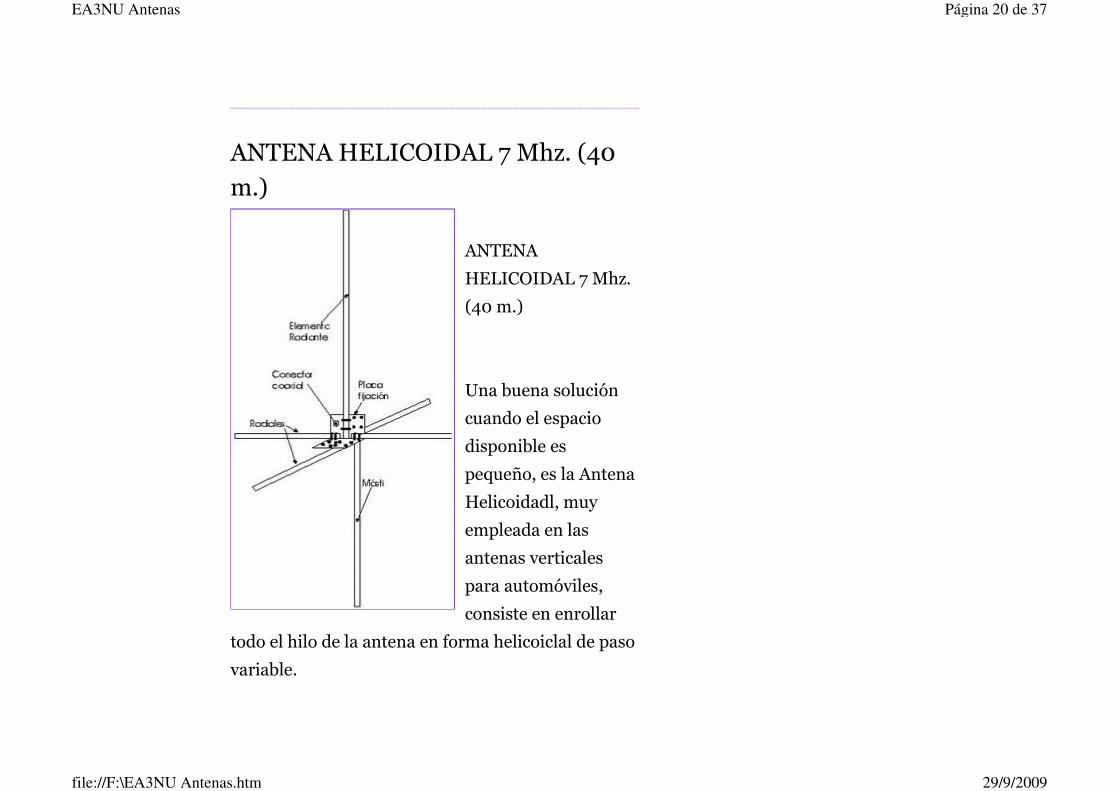
ANTENA HELICOIDAL 7 Mhz. (40
m.)
ANTENA
HELICOIDAL 7 Mhz.
(40 m.)
Una buena solución
cuando el espacio
disponible es
pequeño, es la Antena
Helicoidadl, muy
empleada en las
antenas verticales
para automóviles,
consiste en enrollar
todo el hilo de la antena en forma helicoiclal de paso
variable.
Página 20 de 37EA3NU Antenas
29/9/2009file://F:\EA3NU Antenas.htm

Con este sistema se consigue una bobina a lo largo
de toda la antena, pero con influencia menor en el
punto dé alimentación y mayor a medida que nos
acercamos al extremo.
En todos los casos, siempre se deja en la punta de la
antena algún sistema que permita variar su longitud
total con el fin de ajustarla exactamente a la
frecuencia deseada.
Construcción
El elemento radiante se lo construirá sobre un tubo
de PVC reforzado de 1 1/2" x 3 m. de longitud, el
cual irá montado como muestra la figura sobre una
placa de metal protegida contra la corrosión de
aproximadamente 20 cm. x 30 cm. doblada en "L"
dejando 20 cm en la parte superior donde va sujeto
el tubo, y 10 cm. a 90º en la parte inferior que va
Página 21 de 37EA3NU Antenas
29/9/2009file://F:\EA3NU Antenas.htm

fijada a la superficie que va montada la antena.
El tubo PVC, se lo fija a la placa con
abrazaderas "U" de 1/4" de diámetro.
Sobre el tubo PVC se arrolla 20,8 m de alambre
esmaltado o cable forrado tipo Tw para
instalaciones electricas Nº 14, con un espaciado
regular y que cubra toda la parte superior del tubo
PVC a partir de la placa en la parte inferior.
Se debe cuidar que el arrollado sea firme para darle
la suficiente fijación al alambre sobre el tubo.
Ahora en la punta dejaremos un pequeño látigo de
alambre de aproximadamente 50 cm. y lo
sujetaremos con una amarra o abrazadera plástica
autofijada.
El largo del alambre arrollado debe ser un poco mas
de la 1/2 longitud de onda de la frecuencia de
trabajo.
Página 22 de 37EA3NU Antenas
29/9/2009file://F:\EA3NU Antenas.htm

Esta versión puede funcionar perfectamente en el
patio de su casa, o incluso en la terraza pero con la
condición de que esté conectado a una buena tierra.
Ahora, si la vamos a utilizar la antena elevada del
piso con un mastil, entonces será necesario
construirle cuatro o tres radiales fijados en la parte
inferior de la antena.
Estos radiales son de construccion similar al
elemento radiante solo que pueden ser de tubos de
1" por 2 m. de longitud. Sobre este tubo se arrollará
1/4 de longitud de onda más aproximadamente un 7
% del mismo alambre utilizado para el elemento
radiante, aproximadamante para nuestro caso 11
metros.
Página 23 de 37EA3NU Antenas
29/9/2009file://F:\EA3NU Antenas.htm
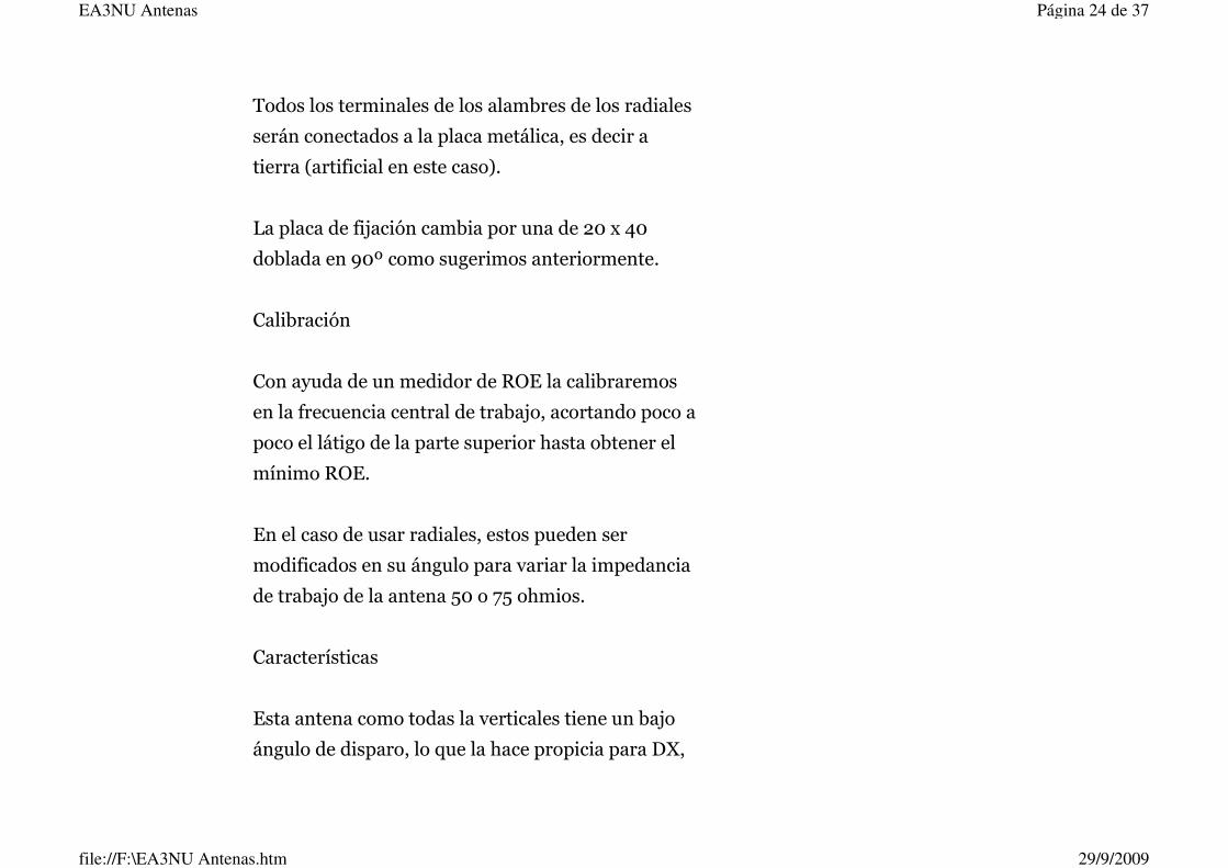
Todos los terminales de los alambres de los radiales
serán conectados a la placa metálica, es decir a
tierra (artificial en este caso).
La placa de fijación cambia por una de 20 x 40
doblada en 90º como sugerimos anteriormente.
Calibración
Con ayuda de un medidor de ROE la calibraremos
en la frecuencia central de trabajo, acortando poco a
poco el látigo de la parte superior hasta obtener el
mínimo ROE.
En el caso de usar radiales, estos pueden ser
modificados en su ángulo para variar la impedancia
de trabajo de la antena 50 o 75 ohmios.
Características
Esta antena como todas la verticales tiene un bajo
ángulo de disparo, lo que la hace propicia para DX,
Página 24 de 37EA3NU Antenas
29/9/2009file://F:\EA3NU Antenas.htm

su tamaño compacto la hace muy práctica, y tiene
una ganancia en dB como una antena 1/4 de onda
plano-tierra.
Al ser compacta, tiene un factor Q estrecho y por lo
tanto un ancho de banda también pequeño, lo que
no le permite trabajar con una baja ROE en toda la
banda, además como todas las verticales tiene una
recepción algo ruidosa.
Pero para los colegas amantes de la
experimentación estoy seguro que les dará gratas
horas de trabajo.
PUBL ICADO POR RAMON EN 22 : 01 0 COMENTAR IOS
ANTENA FACIL Y EFICIENTE
A N T E N A D E S I N T O N I A R E M O T A
ANTENA DE SINTONIA REMOTA
A N T E N A P A R A 1 6 0 Y 8 0 M T S
Página 25 de 37EA3NU Antenas
29/9/2009file://F:\EA3NU Antenas.htm

Antenas - Radioafición - Cebeísmo Diexismo
____________________________________
____________________________________
_________
ANTENA FACIL Y EFICIENTE
No se ría.......FUNCIONA.
Página 26 de 37EA3NU Antenas
29/9/2009file://F:\EA3NU Antenas.htm

Vertical Helicoidal para todas las bandas bajas de
HF
*Apta para Transmisión y Monitoreo
*Factible de elaborar con materiales de desecho
-Dos tubos de pvc resistentes, longitud mínima 1,5
mts. ,diámetro aproximado
1 1/2" o inferior.
-41 mts. de alambre forrado de 1,5 mm.
-42 mts de alambre forrado delgado (cualquier
diámetro, entre 1 y 0,5 mm)
-Conector, abrazaderas, mástil, etc.
ELABORACION
* Arrollar los 41 mts de alambre forrado en el caño
principal irradiante cuidando
que las espiras queden configuradas con un
Página 27 de 37EA3NU Antenas
29/9/2009file://F:\EA3NU Antenas.htm

espaciado más o menos regular.
Soldar en la cúspide a manera de cruz acostada
elsombrerocapacitivo,consistente
en dos alambres entrecruzados de 1,5 mm de
diámetro y de 35 cm de largo c/u.
* Arrollar los 21 mts. del alambre forrado delgado
en cada uno de los radiales.
* Para evitar cambios en las configuraciones de
arrollamiento, en ambos casos, fijar
los alambres a los tubos con amarras pláticas o con
cintas adhesivas.
Versión Monobanda Banda 40 mts. Banda 20 mts.
Longuitud cable irradiante = 20,8 mts. 10,6 mts.
Longitud cable radiales = 11,0 mts. 5,9 mts.
AJUSTES
Versión Multibanda
En este caso será necesario la utilización de
Página 28 de 37EA3NU Antenas
29/9/2009file://F:\EA3NU Antenas.htm

cualquier tipo de caja auxiliar de
sintonización de antena. Para el caso de su uso en la
banda de 80 mts y cualquier
otra, seguir las intrucciones para la versión
monobanda.
Versión Monobanda
* El largo del cable arrollado en el irradiante deberá
corresponder siempre a una
longuitud aproximada de un poco más de 1/2 onda.
* Para ajustar la R.O.E a valores mínimos se deberá
acortar o alargar el tramo
superior del cable irradiante (sombrero capacitivo),
hasta lograr una lectura
adecuada de estacionarias. Optativamente se puede
variar el ángulo de caída de
los radiales para así cambiar la impedancia.
* El largo de cable arrollado en los radiales deberá
corresponder a un 7% mayor
que un 1/4 de onda, siéndo esta medida nunca
crítica.
Página 29 de 37EA3NU Antenas
29/9/2009file://F:\EA3NU Antenas.htm

Comentarios:
Lo Malo : * Estrechez de factor Q * Necesidad de
agregarle radiales extras si la
se sitúa a menos de 6 metros del suelo. * Recepción
de ruido típico de las antenas verticales. * Discretos
resultados de 21 a 30 MHz.
Lo Bueno: Bajo ángulo de disparo, especial para DX
lejanos, (lobulación en
"8 gordo"). Tamaño compacto, lo que conlleva una
mínima utilización de espacio. Ganancia en
decibeles casi equivalente a la de una antena ground
plane de 1/4 de onda, lo que hace atractivo su
utilización en las bandas bajas.
Antenas para TV Cable - Tv Satelital - Intranet -
Internet
Página 30 de 37EA3NU Antenas
29/9/2009file://F:\EA3NU Antenas.htm

Antenas - Radioafición - Cebeísmo - Diexismo
PUBL ICADO POR RAMON EN 15 : 00 0 COMENTAR IOS
Suscribirse a: Entradas (Atom)
A N T E N A D E S I N T O N I A R E M O T A
ANTENA DE SINTONIA REMOTA
A N T E N A P A R A 1 6 0 Y 8 0 M T S
Página 31 de 37EA3NU Antenas
29/9/2009file://F:\EA3NU Antenas.htm

TO CONSTRUCT THE 160M LOOP
YOU'LL NEED 20FT ON RG-59. FOLD
THE RG-59 IN HALF. ON THE 160M
LOOP, IT WOULD BE ABOUT 10FT
FROM THE END. ON THE 80M LOOP,
IT WOULD BE ABOUT 5 FT. FROM
Página 32 de 37EA3NU Antenas
29/9/2009file://F:\EA3NU Antenas.htm

THE END. YOU THEN MARK THE CENTER, THEN MEASURE 1/2
AN INCH ON BOTH SIDES. STRIP AWAY THE OUTER CABLE, THE
BRAID, AND THEN THE FOIL COVERING THE CENTER
CONDUCTOR INSULATION. I THEN USUALLY USE HEAT STRINK
TO WEATHERPROOF WHAT I 'VE CUT AWAY.THEN CUT SOME
SCHEDULE 40 ONE INCH PVC PIPE INTO 3 LENGTHS. EACH
SHOULD BE 45 INCHES LONG. CUT ONE TO 56 INCHES. THAT
ONE WILL BE THE MAST.ASSEMBLE THE LENGTHS YOU CUT
INTO A "T" CONFIGURATION. MEASURE FROM THE CENTER 43
1/4 INCHES ON THE THREE 45INCH LENGTHS. DRILL A HOLE
LARGE ENOUGH TO PASS THROUGH THE RG-59. FOR THE 80M
LOOP. DRILL THREE HOLES 20 1/2 INCHES MEASURED FROM
THE CENTER OF THE "T" . LOOP THE 20FT RG-59 THROUGH THE
HOLES DRILLED AT 43 1/4 INCHES, THEN LOOP THE 10FT
LENGTH THROUGH THE HOLES DRILLED AT 20 1/2 INCHES.
INSTALL THE MALE TYPE "F" AND WEATHER BOOTS ON THE
RG-59 YOU JUST LOOPED THROUGH THE "T". ATTACH THE 20FT
CABLE TO THE 160M MATCHING BOX. ALSO DO THE SAME WITH
THE 80M BOX. I FIND IT EASIER TO AIM THE 160M BOX WITH
THE SO-239 DOWN. AND THE 80M BOX WITH THE SO-239 UP.
THAT WAY THE IT WILL KEEP THE HARNESS SHORT. DRILL THE
Página 33 de 37EA3NU Antenas
29/9/2009file://F:\EA3NU Antenas.htm

MOUNTING HOLES THROUGH THE BOX, ONCE YOU PULL THE
LOOP TIGHT.TO TUNE THE LOOPS, ATTACH EACH LOOP
SEPARATELY TO YOUR TRANSCEIVER. DO NOT APPLY RF TO
THE LOOP. THIS WILL DAMAGE THE COMPONENTS, AND
PROBABLY YOUR TRANSCEIVER. PLACE THE DIAL OF YOUR
TRANSCEIVER TO THE PART OF THE BAND YOU WANT TO USE
THE LOOP ON. THEN ADJUST THE THE TRIMMER CAPACITOR
FOR MAXIMUM NOISE. DO THIS FOR BOTH LOOPS. THEN
ATTACH THE HARNESS. THE LOOPS SHOULD BE READY FOR
USE. I USUALLY WEATHERPROOF THE BOXES AND FRAME. AND
I ADD A WOOD DOWLING TO STRENGTHEN THE MAST.
I N D U C T O R E S O B O B I N A S D E C A R G A P A R A A C O R T A R A N T E N A S
INDUCTORES O BOBINAS DE CARGA PARA ACORTAR ANTENAS
CUANDO EL FLUJO DE LA CORRIENTE VARÍA, EL CAMBIO
RESULTANTE EN EL CAMPO MAGNÉTICO ALREDEDOR DE UNA
BOBINA INDUCE UNA TENSIÓN SOBRE ESTA QUE SE OPONE A
LA TENSIÓN DE ALIMENTACIÓN, POR LO QUE MANIFIESTA UNA
PROPIEDAD DE AUTOINDUCTANCIA. LA CANTIDAD DE
AUTOINDUCTANCIA, DEPENDE DEL NÚMERO DE VUELTAS DEL
ENROLLADO, DEL DIÁMETRO DE LA BOBINA, LA FORMA DEL
ENROLLADO, EL TIPO DE NÚCLEO COMPUESTO DE
Página 34 de 37EA3NU Antenas
29/9/2009file://F:\EA3NU Antenas.htm

SUBSTANCIAS MAGNÉTICAS O SIMPLEMENTE EL AIRE. PARA EL
CASO DE LA BANDA DE TRANSMISIÓN QUE DA COMO
RESULTADO UNA ANTENA DEMASIADO LARGA (40 Y 80
METROS), ES POSIBLE ACORTAR LA MEDIDA FÍSICA DE SU
LARGO, A TRAVÉS DEL USO DE INDUCTORES O BOBINAS Y CON
ELLO PARA LOGRAR LA RESONANCIA. LA PROPIEDAD
ANTERIOR, SE LOGRA ESO SI , SACRIFICANDO EL ANCHO DE
BANDA DE LA ANTENA. AUNQUE ÉSTA NO SEA TAN EFECTIVA
EN TÉRMINOS DE GANANCIA, TIENE LA GRAN VENTAJA DE
OCUPAR MENOS ESPACIOS Y PARA EL CASO DE LOS ARREGLOS
DIRECCIONALES DE DOS Y TRES ELEMENTOS BAJA SU
RESISTENCIA AL VIENTO, SU RADIO DE GIRO, ETC.
A N T E N A T A K - T E N N A
Página 35 de 37EA3NU Antenas
29/9/2009file://F:\EA3NU Antenas.htm

R E U S M A P A
Página 36 de 37EA3NU Antenas
29/9/2009file://F:\EA3NU Antenas.htm

VER MAPA MÁS GRANDE
Página 37 de 37EA3NU Antenas
29/9/2009file://F:\EA3NU Antenas.htm

0
0.5
1
1.5
2
2.5
26.8 27 27.2 27.4 27.6 27.8
Resonant Frequency chosen at 27.15 MHz
SW
R
TAK-tenna 11 Meters
Resonant frequency is chosen by user at time of tuning.
50 Ohm coax direct from rig to antenna.

I purchased the Tak-Tenna for 20 meters. Assembles according to the good instructions in about 1 hour. Tuned it at about 12 feet for 14.280. The first CQ I heard was in Honduras. I answered back and after the second time He acknowledged me with a 5/9! Wow! This Tak20 really works good. I have made many more contacts depending on band conditions. I feel that it outperforms my inverted V and it is so much smaller and less obvious which is good in my neighborhood. For a wire antenna, This thing is great. I also have to add that Steve was a great help, he even helped me over the phone. If you are even thinking about buying one of these I would say buy it, you won’t be disappointed. 73 KE5MBW

Amateur Radio Station
Zone: CQ 14-ITU 37 LOCATOR: IM 99 TL
Inicio l Noticias l Download l Shop l Links l Foro l Contacto l
English
La TAK-tenna es un dipolo compacto de media onda con espirales radiales en sus extremos. Existen varios modelos, el modelo probado es de la banda de 40 metros. Vamos a ver su montaje:
Página 1 de 3
29/9/2009file://F:\tak-tenna.htm

Aquí vemos las piezas de la TAK-tenna y las instrucciones
de montaje, tal como recibimos el paquete.
Detalle de algunos de los elementos.
Introducimos las barras cortas que sujetarán las espirales, en
el boom, con bridas para que no se muevan.
Una vez montadas las barras, las pintamos de blanco para
que la antena quede más vistosa.
Procedemos a montar uno de los alambres en una de las
cruces, dibujando una espiral, y lo sujetamos con bridas.
Hacemos lo mismo en el otro lado, pero en sentido contrario, y el resultado es el que vemos
en la imagen.
Conectamos el hilo de alimentación coaxial al boom
(cortamos el hilo por la mitad, y a cada mitad le ponemos en un extremo un borne de contacto y
en el otro una pinza de cocodrilo).
Página 2 de 3
29/9/2009file://F:\tak-tenna.htm

Una vez conectado vivo y masa a uno de los espirales, procedemos en primera instancia a hacer el ajuste de la frecuencia tomando como referencia el ajuste que nos viene en las instrucciones. Según nos indica el
fabricante la espiral que va alimentada por el vivo del coaxial, nos da la frecuencia y la espiral que va conectada a la malla del coaxial, regula las estacionarias. Y este es el resultado final. ¡A disfrutar!
Conectamos el cable al lado derecho.
Conectamos el cable al lado izquierdo. Es conveniente hacer
ajustes de sintonía para comprobar el funcionamiento
antes de la instalación definitiva.
Op. Alfonso Martí P.O. BOX: 9038 CP: 46080 Valencia (Spain) - QSL via direct or bureau
Página 3 de 3
29/9/2009file://F:\tak-tenna.htm

View Single Post Thread: Bill's- HomeBrewed Pan Cake - 40 Meter TAK-tenna
06-12-2008, 05:15 PM
Old
KA6KBC's Avatar
KA6KBC Ham Member
KA6KBC is offline
Join Date: Jan 2006 Location: Yorba Linda, CaPosts: 36
Bill's- HomeBrewed Pan Cake - 40 Meter TAK-tenna
So I've been reading about this Small Space antenna that is being sold as the TAK-Tenna. Really neat idea - Has a 30 inch boom and Spiral Coils on the ends. See a picture at
http://www.taktenna.com/ Looks easy to build - Right ?
So I Built my version out of wood - Mine is very ugly as compared to the store bought one. Materials:
Parts: • 3 - Wooden sections - 1 1/2 in X 1/2 in X 8 ft - Cost 92 Cents each - Home Depot
• 1 - 100' Spool of Steel Guide/fence Wire - Cost - $7 - Home Depot
• 1 - 25 foot RG8 coax with PL259 - Radio Shack - Close Out - $5 • 2 Packages - Nuts/Bolts - $2 - Home Depot
• Total Material Cost: $16.76 The commercial version uses PVC and tie wraps, which would have been much easier.
Fab Time for my version was about 4 hours - Drilling Lots of Holes and feeding the wire in to make the Spiral Coils was most of the work.
However - Test wise it isn't bad I got it tuned up on 40 meters at about 8 feet off the ground and it has an SWR 1:2 to 1:5 from 7.30 to 7.175 MHZ. Also does ok on 15 meter - Tune up wise.
Bad news the performance is not Great - Signal pick up is several S units below my Dipole, but it does work.
From what I have read the Antenna has problems in that most of the performance is based on feedline radiation (See the links below).
http://lists.contesting.com/archives.../msg00339.html http://groups.google.ie/group/rec.ra...7fb7a34305cf3e
I'm still testing and will upload a picture of my ugly version at some point
It was an interesting experiment and the Antenna fits into a small space 24 inch X 30 inch. Hey it works. If you have no space it might be worth $20 and a few hours of your time or If you aren't a Homebrewer Buy one.
Default
Página 1 de 2QRZ Forums - View Single Post - Bill's- HomeBrewed Pan Cake - 40 Meter TAK-t...
21/9/2009file://F:\showpost.php.htm

If you make your own one point - I needed more wire than the 468/7.2 MHZ = 65 Feet Total
or 32.5 Feet per side - I had to add wire after the fact. So I would make it about 33.5 per side. Any thoughts ?
- Bill - KA6KBC - 73's
Antenna - Pictures: http://www.myhamshack.com/HamShackPi...Antenna_3.aspx
http://www.myhamshack.com/HamShackPi...Antenna_1.aspx
Last edited by KA6KBC; 06-14-2008 at 03:25 AM. Reason: Added - Links to pictures
Reply With Quote
Página 2 de 2QRZ Forums - View Single Post - Bill's- HomeBrewed Pan Cake - 40 Meter TAK-t...
21/9/2009file://F:\showpost.php.htm

The TAK-tenna Review -Restricted and Limited Space HF Antennas -... http://www.hamuniverse.com/taktennareview.html
1 de 19 20/9/2009 00:25
SEARCH
CQ - Calling All
Hams!
Are You New to
HF?
Good info for
Techs!
New Novice, Tech
and Tech +
Privileges
About
Hamuniverse
Antenna Design
Ask Elmer
About Batteries
Code Practice
Computer Help
Electronics
Emergency Power!
FCC Information
Ham Hints -
Humor
Ham Radio News!
HF & Shortwave
License Study
Links
Midi Music
Reading Room
Repeater Basics
Repeater Builders
Info
RFI Tips and
Tricks
Ham Satellites
Shortwave
Listening
SSTV
Support The Site
STORE
Vhf and Up
Contact
Site Map
Privacy Policy
Legal Stuff
Sign/View Log
The TAK-Tenna™ ReviewA Limited Space HF Antenna Review
The TAK-tenna™ by Don Butler, N4UJW
Hamuniverse.com
(Note: This review was originally done in May, 2007 when theTAK-tenna first came out
and has been updated since then)
Why am I doing this review? I don't review antennas! I don't recommend antennas!
As you may know, a big percentage of this web site isdedicated to building antennas and not buying them, but sometimes an antenna comes along that is so unique that itdeserves my attention.....and yours! If I normally did antenna reviews then I would probably getright into it but a bit of introduction is needed to help youunderstand why I am reviewing the TAK-tenna. Prepare for some reading. What's that? You just want the bottomline.....BUY IT!
The Space Problem and Murphy's Law!
Most of you have heard of "Murphy's Law"...you know...heis around when everything goes wrong that can go wrong.
Many hams just don’t have the space to put up standardlength HF half wave dipole antennas but would give theirleft arm to operate on the HF bands without being limited inone way or another due to space. Many hams are sorestricted that HF antennas, due to their length on the lowerbands, are almost totally out of the question. In lots ofsituations, even a simple half wave dipole on 40 meters justwill not fit.....Murphy's law.
Yours truly is limited by the lack of natural supports for anykind of antenna due to being on a lot with absolutely notrees! So if an antenna that I have needs support, then Ihave to either build it or buy it. Mother Nature has nothelped me in any way and the XYL hates guy wires and“junk metal poles“ all over the place.
Hams like myself are limited by too many trees, not enoughtrees, antennas requiring various supports, property lines,overhead power lines, home owners association rules,
TDK Horn
Antenna 1-18GHzWide band, double-ridged horn High gain, low VSWR, robust design www.tdkrfsolutions.com
Antennas for
OrbcommLow Profile, Small Footprint Combination antennas for Orbcomm www.multiband-antennas.com
KJ7U
Screwdriver
Antennas6 through 160 meter mobile antennas High Quality Shorty or Full Size www.kj7u.com
Horn Antenna
ExpertStandard Gain Horn up to 110GHz Broadband Horn up to 40GHz www.ainfoinc.com
The TAK-tenna Review -Restricted and Limited Space HF Antennas -... http://www.hamuniverse.com/taktennareview.html
2 de 19 20/9/2009 00:25
Book!
Crucial's
System
Scanner finds
the right
memory!
layout problems with small city lots and on and on. If a ham can be restricted or limited with the antenna system layoutfor his HF antenna, then Murphy's Law will kick in and seethat he will remain restricted in some way. I am certainMurphy has many twins and one of them has probablyvisited you at one time or another in your search for an HF antenna that will fit your space.
Can you imagine needing about 65 feet horizontal distanceto put up a 40 meter horizontal wire dipole or inverted Vand all the space you have is just enough BUT.....theneighbor’s fence and that power line is in the way. Murphyjust kicked you! So you look around and find anotherpossible location....nope....the top of the house will be tooclose and there is no way to get around that tree!Murphy.....again! Climb the only available 50 foottree....what...no safety harness......slingshot practice in thedark.... ....what was that sound.........glassbreaking?......Murphy again.....How about that twig of astick you call a tree......too short....shut up Murphy....what isa ham to do?
I get many emails from hams in similar situations wantingsuggestions for limited or restricted space antennas for HFoperation and in some cases, I have to do research on theweb to come up with a good suggestion for a limited space antenna that is workable on HF. Of course, much dependson the particular layout of the QTH.
The problem with most HF antenna layouts is the lack ofhorizontal space and supports and in most cases going up is the only alternative but for one reason or another avertical is out of the question with all those radials that youjust don't have room for....Murphy again.....what is theanswer? Well, maybe I have found an easy andinexpensive way to kick Murphy away from your limited"antenna farm" permanently!
The TAK-tenna Compact Concept!

The TAK-tenna Review -Restricted and Limited Space HF Antennas -... http://www.hamuniverse.com/taktennareview.html
3 de 19 20/9/2009 00:25
NO....it is not a vertical nor one of those EH antennas!
It is an electrical half-wave dipole believe itor not!
I may have found one very usable antenna that should workin most locations unless your QTH is located in the doghouse.....but you still may have room! Let me explain!
One day while searching the web for unusual antennas, Iwas introduced to a “new” concept, (to me), an electricalhalf-wave dipole based on what is called the Petlowanyprincipal of spiraling a 1/4 wave length “pancake” of wire oneach end of a greatly reduced boom length yielding anantenna that was very usable as far as size was concerned.What I saw was a 40 meter half wave dipole antenna compressed into such a small size that I thought it shouldwork poorly or not at all.
Being the "I want to know" for the sake of knowing personthat I am, I had to find out for myself whether this was abunch of static or not.
I set out to experiment with it at 2 meters using thisprinciple and it proved to me that it worked and workedwell! This was truly a remarkable principle and I had provedto myself that it worked in such a tiny package!
Using the very poorly built wire antenna with junk boxengineering and "make do with what you have" ingenuityusing this Petlowany principal, gave me an antenna that hitrepeaters 60 miles away from inside a single story house over flat terrain! At 2 meters it was made from a brokenyard stick as the boom, and a couple of pieces ofcardboard, tape and some wire. It was straight out of

The TAK-tenna Review -Restricted and Limited Space HF Antennas -... http://www.hamuniverse.com/taktennareview.html
4 de 19 20/9/2009 00:25
hillbilly junk yard junction....but......this contraption actuallyworked! I was hitting 2 meter repeaters 60 miles away over flat terrain.......from inside the house!
Enter the TAK-tenna Company
Now the TAK-tenna company, using principles based onideas by Petlowany and many others all the way back tothe beginning of radio, using some major modifications, lotsof engineering, mechanical and technical improvements,has developed a line of patent pending greatly reduced size HF antennas that may put regular length dipoles in theirplace where they belong....in non-restricted layouts! A 40 meter electrical half wave dipole in a 30 inch spacethat performs?.......I will have to prove it to myself and you the reader with this review!
The TAK-tenna line of antennas are extremely reduced space antennas both horizontally and vertically yet remain electrical half wave dipoles. My idea for this review wasto see if they worked as well as I had hoped they would,given the fact that thousands of hams are very limited withroom for HF antennas and are constantly looking for betterways to get out a better or any signal on the HF bands while having limited or no space for dipoles. And all for theprice of taking the family out to a goodmeal.....unbelievable! We'll see.....
About the TAK-tenna review!
"Just to set the record straight, I am in no way affiliated orconnected with the TAK-tenna company and owe themnothing in return for this review nor do they owe me anything. I will freely admit that they did supply me with anantenna for my review with no strings attached. No, it is nota tweaked and peaked version or their production model soit will pass my review with flying colors if some of you areskeptical....it is just like the one you would get in the box ifyou ordered it from TAK-tenna.
As a general rule, I do not endorse or do any ham radiorelated product reviews nor make recommendations. Mysole purpose of reviewing this antenna is for the benefit ofthe viewers and readers of Hamuniverse.com and to satisfy my curiosity about this new antenna to help hams who maybe looking for a restricted space HF antenna that will helpthem get a better signal out on HF when they arelimited with space.
I happen to enjoy helping other hams with their antenna

The TAK-tenna Review -Restricted and Limited Space HF Antennas -... http://www.hamuniverse.com/taktennareview.html
5 de 19 20/9/2009 00:25
limitations and questions and if I don’t know the answer, Iwill do my best to find it for you as many of you have foundby the emails you have sent me. If my review of thisantenna turns out negative...then my advise for what it isworth would be..... don't buy it....but if it turns out positive inmy opinion, then it would be well worth your considerationfor a limited space hf antenna.
This review for the TAK-tenna may help you decide to tryit....or not. It makes no difference to me but I do know thatthis "type" of antenna......WORKS and the principles behindit are sound and repeatable.....but a paper clip will radiate rf too....to some extent! Let’s see how this limited space antenna compares to apaper clip or wet noodle and my center fed multibanddoublet and a ground mounted vertical that are notrestricted....except by the XYL!.......but wait......that's not afair comparison...or is it?N4UJW"
Background of the TAK-tenna company
The TAK-tenna antenna design is the brain child ofStephen Tetorka, WA2TAK, U.S.A.
The company name, TAK-tenna, LLC, was derived frompart of his call sign."Steve, WA2TAK, has a Master's in Engineering...spent25+ years in Engineering/Manufacturing...including severalyears with NASA. There's a 30% chance you are within an arms distance from one of his products -- he co-developed the special wire used to make the motorwinding for Seagate Technology's hard disk drive that mightbe in the computer you are using right now.".....Source QRZ.COM - WA2TAK
The TAK-tenna Antenna:
This information below with the yellow background wastaken directly from their web site and slightly edited for space on this page. None of the content from their webpage has been re-worded. All of the pictures of theTAK-tenna below were taken during the tuning andoperating phase of this review.
Electrical Half-wave Dipole Antenna
Electrical Quarter-wave radiating spiral end elements
Rotable Portable Stealth Perfect Backup Antenna
Direct feed with 50 ohm coax on resonant bandCan use coax + tuner...or twin lead + tuner - FB

The TAK-tenna Review -Restricted and Limited Space HF Antennas -... http://www.hamuniverse.com/taktennareview.html
6 de 19 20/9/2009 00:25
Power tested to 1000 CW watts, key down for 30 secondsand 1400 Watts PEP...all FB.
NO lossy matching components anyplace in system10 to 14 dB signal increase in transmit with 90 degree
rotation
30 inch boom
Low SWR across band
Sturdy and well builtWeighs only 5 pounds
Uses proprietary #14 gauge copper plated alloy wireEasy assembly about 45 minutes
(TAK-tenna during tuning phase for this review)
Tested, Proven and Endorsed by Collins Radio Association
TAK-tenna LLC, 154 Lexington Avenue, Fair Haven, New Jersey 07704Telephone 732-530-8530
WA2TAK..( enter call sign on www.QRZ.com)[email protected]
Original Tak-tenna ad back in May, 2007 (Edited for space on this page)
The TAK-tennas are available in 3 models - 40, 20, and 10meters.
The 40 meter model can be used on 40, 30, 20, 15, and 10

The TAK-tenna Review -Restricted and Limited Space HF Antennas -... http://www.hamuniverse.com/taktennareview.html
7 de 19 20/9/2009 00:25
meters with a tuner.
Quoted from Steve Tetorka, WA2TAK - TAK-tenna-"If we have made a small contribution, it is because we
stand on the shoulders of those who preceded us"......"spiral antennas goes back to early 1900's...the
'spider' which generally sat on top of the wood cabinet ofthose TRF AM broadcast radios......"
THE REVIEW
The model we evaluate is the 40 meter model due to thefact that it can be fed with either 50 ohm coax, for single
band operation or you can use it with twinlead or coax anda tuner for the additional bands of 30, 20, 15, and 10
meters for a total of 5 HF bands. It comes in kit form as dothe other models and at the present time, according to
TAK-tenna, is the most popular because of this feature. Other models are in the research stage. 80 meters and
others?......could be!
My evaluation for this review will be based on a scale of 5for each criteria with 5 being a perfect score for each
criteria and I have attempted to choose the most importantcriteria that most hams will be looking for and also added acouple of my own so this review scoring system may not be
what you were expecting and is the result of my opinionand my opinion only.
Now that you have been introduced to the TAK-tenna,
let's get on with the review!

The TAK-tenna Review -Restricted and Limited Space HF Antennas -... http://www.hamuniverse.com/taktennareview.html
8 de 19 20/9/2009 00:25
40 Meter Tak-tenna reviewed 11 feet off theground!
(There will be a total of 20 review criteria listed below for amaximum possible point score of 100. You will see mycomments after the score for each of the criteria and notethat this review in no way is to be considered a computer model simulation or results from an antenna testrange....this review is just my observations, and end userthoughts and comments from a regular ham like yourself.)I have attempted to do this review with the ham in mind thathas limited space for HF antennas!
THE SCORES!
1. The most important criteria of my review will be theon the air performance! (5) If I could give it a 10, I would!I can confirm that I had so much fun with this antenna onthe air that I almost forgot about doing this review! It is aremarkable antenna for it's size! Nearly all of the contacts I

The TAK-tenna Review -Restricted and Limited Space HF Antennas -... http://www.hamuniverse.com/taktennareview.html
9 de 19 20/9/2009 00:25
made were 5 9 reports during less than favorable bandconditions using an old Yaesu FT 107, 100 watts, SSB on40, 20, and 17 meters...Yes 17 meters too! Cuba was loudand clear giving me a 59 report....and the TAK-tenna wasonly 11 feet off the ground during all of the on the air testing. I can not stress enough the fun I had reviewingthis antenna on the air!And as an added note, no one on the other side of anyconversation over the air knew what antenna I was running.I only said that I was using a 40 meter dipole up 11 feet and the QTH was Texas, near Dallas.
Other considerations:2. Clear and easy to understand instructions? (4.5)
I followed the instructions exactly as written in the manualin the order that they were written and did not jump aroundbetween steps.The instruction manual contains good quality pictures anddrawings that are very helpful but some of you less experienced builders may like to see a drawing of thecompleted antenna with part descripions, and theirlocations with reference numbers....especially concerning the way the support tubes attach to the boom with nylonties as noted below. Even one drawing or picture of thesupport tube/boom junction point would have been helpfulto some builders.
Most of the instructions were very clear indeed, howeverwhen attaching the supports to the boom, I did notice thatthere were holes drilled in the center of each support armwhen I took them out of the box. There was no mention ofwhy they were there in the instructions. With a bit offurther investigation and logic, I determined that they arethere so you can use them to feed the nylon ties into the holes and around the boom so the support arms can besecurely attached to the boom. The support arms are notbolted to the boom but using the nylon ties in the propermanner makes for a very sturdy setup!
One other very minor thing, (to me), was the fact that youare instructed to cut a 26 inch length of wire from thesupplied length in the kit to use as a connecting wire fromone side of the feed connection to one of the spirals, withno mention about the left over wire or where it goes. Veryshortly, using simple logic, there is only one option. It has togo to the other spiral. This could be slightly confusing to anon-experienced antenna builder. I pretended I was thatperson!
Other than this, instructions were excellent!

The TAK-tenna Review -Restricted and Limited Space HF Antennas -... http://www.hamuniverse.com/taktennareview.html
10 de 19 20/9/2009 00:25
3. Ease of assembly, any missing parts, assembly timerequired? (4.5)
This score should probably be a 5 but due to the fact that it took me about 1 hour and 15 minutes from unpacking tofinal completion during the assembly portion, I decided thatthe "about 45 minutes" statement on their web site shouldbe lengthened a bit.
UPDATE: The Tak-tenna website now states "Easyassembly - less than 90 minutes" rather than the original "45 minutes" back in May, 2007.I realize that this may be a bit picky but this is the way I seeit. Guess this is a play on words on my part and it would alldepend on many variables with individual builders. I in no way mean this to be understood as false advertising!I did take my time to "get it right" the first time.
I also must admit that the very novel method of attachingeach spiral to the support tubing using notches and nylonties on the tubing is an excellent idea. I am commiting thatone to memory for future home brew projects! If I hadincluded just this one simple idea as another review criteria,it would have gotten a 10! Great idea Steve!
4. Any special tools or test equipment required forassembly or tuning? (5)
By following the instructions which were well written, all youreally need is just a standard HF swr meter and an hf radiocapable of 40 meter operation, a tuner if multiband operation is desired, 50 ohm coax or twinlead, measuringtape, screw driver, soldering GUN, solder, wire cutters anda tool to tighten the mast clamp to the mast or your ownpreferences for tools. The average ham should alreadyhave these.
5. Can the TAK-tenna be put on the air with acceptableperformance using a tuner without tuning theantenna for lowest swr during the "tuning" portion ofthe instructions by just following the instructions likesome other commercial antennas on the market? (5)
You can almost call this antenna PLUG AND PLAY! Winding the spiral coils onto the supports could be a bittricky for some builders, but the instructions are VERY clearon the procedure. Just take your time. I found this very easy. Simple tips are given in the instruction manual forwinding and as I mentioned above, the novel idea of the

The TAK-tenna Review -Restricted and Limited Space HF Antennas -... http://www.hamuniverse.com/taktennareview.html
11 de 19 20/9/2009 00:25
notches in the support arms for the spirals make winding asimple process.
By using the "starting tap points" suggested in theinstruction manual, the swr was about 2 to 1 using an MFJ259B antenna analyzer on the 40 meter band down near the lower portion of the band. This swr should pose noproblem for a tuner using the initial starting tap points. Please not though that due to your individual constructionpractices, the initial swr reading may different for you.
6. Any special or unreasonable restrictions on location,mounting or height above ground? (5) SEE UPDATE AS OF 11-30-08 BELOW!I installed it for the original review at 11 feet from theground exactly at the boom and it tuned as expected usingthe instructions. Why did I use 11 feet? This is the length ofan old CB vertical section I had laying out in my "junk pile" as my XYL calls it, of aluminum tubing. As you builders outthere know, we call it "gold".I have not attempted to operate it lower than the 11 feet inthe original testing in May, 2007. There are reports that it"works" below this limit and I have confirmed them in theupdate below! UPDATE (11-30-08) I have confirmed that...the TAK-tenna has been operated as low as 2 feet above ground - on acamera triopod - in vertical propagation orientation...and aslow as 5 feet above ground in horiztonal propagationorientation so this would certainly add to it's versatility!
7. How does it perform at extremely reduced heights?(5)
I have not personally tried the Tak-tenna at other than11 feet but according to the many other reports I haveread, it performs well down to 2 feet above ground inthe vertical orientation. I have not used it at any height below the 11 feet heightabove ground in the testing. Others have reported goodresults down to 2 feet as in #6 above.So to be fair with this review, I gave it a 5.
8. Does it require more than one person to assembleand mount? (5)
Unless you are severely disabled, you should not have anyproblem with any part of the assembly or mounting. Thisantenna is so light, 5lbs, that it is indeed very easy toassemble and get in the air by one person!

The TAK-tenna Review -Restricted and Limited Space HF Antennas -... http://www.hamuniverse.com/taktennareview.html
12 de 19 20/9/2009 00:25
9. Was it easy to tune for lowest SWR? (4.5)
I don't know of many, if any, commercial orhomebrew antennas that are perfect when it comes totuning. There is NO cutting or trimming of this antenna required or suggested to get a good low swr. I was able toget it down to about 1.5 to 1 swr by some expected trial anderror by following the instructions using the alligator clipssupplied for initial tuning of the tap points on each spiral.Don't get discouraged, it is very tunable for low swr on 40meters! Do not expect low swr on any other band other than the resonant band of 40 meters. Remember, this is an electrical half wave antenna. I didnote that the swr was usable on 15 meters as would beexpected unless you are a perfectionist. As the manual states, there may be rf on the shield so follow theinstructions and suggestions supplied in the manual anddon't let this fact worry you....the antenna will perform!
10. Was the SWR low over a good usable range asdetermined by the MFJ259B as a test meter? (4.5)
YES! I suspected at the beginning of the review that afterfinal tuning during the initial setup that the TAK-tenna maybe very narrow banded on some bands. However, when using a tuner, and 50 ohm coax feed, at 11 feet off theground, I found that the usable range on most bands wasvery adequate without having to retouch the tuneradjustments. 10 meters was a bit tricky with an MFJ 901B tuner, but with some very fine tuning of the controls, it fellright into 1 to 1 swr at 28.400mhz!
And for you "Techies" out there, the MFJ 259B showed mea match efficiency of 99% at 7.1668mhz with an swr of 1:1 and at 21.590mhz, 98% with a 1.2 to 1 swr at the shackend of the coax if you put much faith in the very popularMFJ antenna analyzer.
11. Mechanical stability and material quality? (5)
EXCELLENT! The TAK-tenna company uses high quality materialsthroughout. I did not find any problem with the constructionquality of anything supplied with it. (The alligator clips supplied for tuning only could be a bitlarger for bigger fingers!)There is extra spiral wire included and plenty of black uvtype nylon ties. Don't worry if you make a mistake during construction and wonder if you have enough wire andties to complete the job....you will! You might even haveenough of the spiral wire for a 2 meter ground plane or

The TAK-tenna Review -Restricted and Limited Space HF Antennas -... http://www.hamuniverse.com/taktennareview.html
13 de 19 20/9/2009 00:25
vertical dipole! I saved mine for a later date!
12. How the TAK-tenna compares on the air to an 80meter homebrew multiband center fed doublet dipolefed with TV twinlead using a tuner up about 30 feet setup in a North to South configuration? (5)
I could not give this test comparison a fair un-scientific testdue to band conditions except on receive, and could not geta steady signal with any antenna I had for a goodcomparison but one thing I quickly noticed during switchingbetween TAK-tenna and the other dipole I had was the factthat I HEARD no noticeable difference on any band. I foundthis remarkable compared with about 123 feet of wire upabout 30 feet! The on the air tests in #1 above proved tome how well this antenna works for it's size. 13. How does it compare to a ground mountedmultiband commercial Hustler 4BTV vertical with noradials and fed with RG58 coax? (5)
Again, I HEARD no noticeable difference except thatforeign broadcast did seem to be just a bit "louder" on the4BTV and the S meter confirmed less than 1 S unit difference if you can put much faith in S meters. I am surethat this could be due to the angle of radiation of thevertical being lower than the TAK-tenna, but in any case,21 feet of commercial antenna compared to 30 inches.....you be the judge!
I am even considering using the 4BTV Hustler vertical asan expensive 21 foot mast for mounting the TAK-tenna on top of it in the future!......But then there is Murphy's law andthe XYL stepping in....I may have to use some guy ropes!The XYL hates guy ropes and wires! Go away Murphy!
14. If used with a rotor, can it help to "null" out stationsin undesired locations? (5)
This was a test of the TAK-tenna I conjured up using thecharacteristics of a "rotatable dipole" compared to theTAK-tenna and is not, in my opinion, a fair test due to thefact that TAK-tenna makes no references to the fact that itcan "null" out stations off the side.The TAK-tenna web site states "10 to 14 dB signal increase in transmit with 90 degree rotation". This tells me that ifthe TAK-tenna is rotated toward a station under controlledconditions, ( a good steady signal), and an S meter readingis taken, then if the TAK-tenna is rotated 90 degrees, thesignal should drop about 10 to 14 dB.

The TAK-tenna Review -Restricted and Limited Space HF Antennas -... http://www.hamuniverse.com/taktennareview.html
14 de 19 20/9/2009 00:25
I am putting words into this that TAK-tenna does notstate. They make no statements to the effect that thisantenna is directional, but in my opinion, if it acts like adipole that ordinarily has worst performance off the ends,then this, in my opinion, is what we are seeing here.If you look at the design of the TAK-tenna from an angle of90 degrees to the boom, you see only a very tiny amount ofwire "exposed" in the direction of a station 90 degrees offthe side vs "looking" at that same station "head on". TheTAK-tenna is not a Yagi, and in no way does the companyrefer to it as such, so don't expect that sort of performance from it! This is a very, very compact electrical half wave lengthdipole antenna, no more, no less!
15. Cost versus time saved dealing with MURPHY'SLAW? (5) EXCELLENT!If you could build this antenna from "scratch" as a completehome brew project, then I believe Murphy's Law would win!I honestly do not think you would save ANY time nor could you save ANY money by attempting any other methodother than ordering one of these antennas from theTAK-tenna company. Just cutting the notches alone for thespiral wire would take a long time plus all the drilling of theother holes required for the boom and spiral supports.For the price of this antenna at the time of this review, howcould you loose and still get out a good signal on HF withyour limited space?
16. Is the TAK-tenna advertising on their web pagemisleading in any way in my opinion? (5)
Absolutely NOT!I could not find one statement on their site that could beconsidered in my opinion as misleading in any way.They do not represent this antenna to be a "miracle"antenna in any form. They do not represent theTAK-tenna as bending the laws of Physics or changingthem in any way. It is designed mainly to be used in limited space situationsfor hams who are restricted to little or no HF operation dueto lack of adequate antenna space among it's many credits.
17. Was it shipped in an adequate container to preventshipping damage? (5)
YES! The antenna was extremely well packaged in a sturdy

The TAK-tenna Review -Restricted and Limited Space HF Antennas -... http://www.hamuniverse.com/taktennareview.html
15 de 19 20/9/2009 00:25
container and survived the rigors of going through the manyhands of Federal Express!
18. If I decide to take it down and use it at anotherlocation like camping or field day, will I have problems with the disassembly and reassembly? (4)This may not be a fair test but I threw it in anyway!This model for this review, the 40 meter version, is onlyabout 30 inches by 30 inches assembled and extremelylight in weight. In my way of thinking, it could be taken off the mast and just put it in the back seat of most cars. Thespiral wires are very stiff but could of course be bentsomewhat out of shape with ruff handling.One recommendation I might have would be that ifyou foresee moving it many times to different locations likecamping or field days, would be to simply modify the boomon each side by cutting in the center of each side andadding a coupler of some sort using short bolts thru theboom while keeping the same boom length of 30 inches.Then it should be just a simple matter of taking the antenna apart leaving two "pancake spirals" and the mast portion ofthe boom left to lay flat. Use your imagination.TAK-tenna makes no references to this one way or theother.
19. If for some reason the antenna breaks at somefuture time, can I easily repair it myself without havingto re-order high priced parts for it? (5)
I am going to really stick my neck out here for theTAK-tenna company to chop off and say yes. I did notdesign the antenna but from outward appearances, there is nothing in it that you could not replace using materials fromHome Depot, Lowes, the hardware store, etc to get it backinto operation. Hopefully there are no reasons why youcould not do this. In my opinion, when antenna companiesuse special materials, components, parts and pieces for their product with the express purpose of making theirproducts non-repairable except when using only theirinflated high priced replacement parts...then they are onlyin business for one thing...and it is not you and I realize also that with many commercial antennas, thereare many machined parts that require special equipment tomake....most hams don't have a production line setup.I see nothing in the TAK-tenna that would require more than everyday hand tools to get it back on the air.I do not get the impression about the TAK-tenna companyconcerning the importance of money over the end user. I believe they are in business for the ham radio operator andnot against him. This antenna could easily sell for $100.00or more and they should sell like hot cakes at that price but

The TAK-tenna Review -Restricted and Limited Space HF Antennas -... http://www.hamuniverse.com/taktennareview.html
16 de 19 20/9/2009 00:25
as of this writing, the TAK-tenna is no where near thatprice!
Sure, they should make a mint with the TAK-tenna.....I wishthem all the best!The most fragile part of the TAK-tenna is the spiral wireused on each end. It should not break under normal uses so I really should not call it fragile. This is proprietary #14gauge copper plated alloy wire and I assume it is madespecifically for this antenna. I am sure that if you feel betterabout replacing anything on the antenna, the company willbe happy to help.
20. How did it perform as a multibander? (5)
EXCELLENT!
This TAK-tenna antenna really shines as a multibander!You will forget how small it is while operating!I can confirm that this antenna should perform well foryou on it's advertised bands with a tuner and I found that40, 30, 20, 17, 15, 12 and 10 meters "tuned" just fine for me giving a bonus of 7 HF bands in such a small space!Your tuner may be different than mine so you may not get this performance...experiment!
I used a very basic MFJ 901B tuner during this review andif it will "tune" this antenna with no problems, then your tuner should too.Like I said at the start of this review, I was having so much fun with this antenna that I almost forgot this was a review!
I made several contacts on 40, 20, and 17 meters using100 watts ssb or less with no report less than an S9 or a 59report under terrible band conditions, summer static and atvarious times of the day. A Cuban station reported 59 copyon 17 meters. 15, and 10 meters were "dead" during theinitial on the air testing. I did not do on the air testing on 30meters but receive was fine. I see no reason why 30, 15 and 10 meters should not do well with average bandconditions and due to the fact that I wanted to get thisreview out to you as soon as possible is the reason I havenot tried it on those bands.
Technician class hams should have a ball when 10 metersstarts booming and this antenna should get them on the lower CW bands now!
This antenna has so many possibilities in my opinion when you are limited for HF antenna space. Although the

The TAK-tenna Review -Restricted and Limited Space HF Antennas -... http://www.hamuniverse.com/taktennareview.html
17 de 19 20/9/2009 00:25
instruction manual plainly states that this antenna is notrecommended for use inside....I know the experimentingnature of most hams will win over them and lots of hams will try it in their attics, garage, balcony, etc.
The thing that really impressed me about the TAK-tenna isthe fact that during all of the fun I had with it on the air, Iseemed to forget it was a "tiny" 40 meter antenna not longer than 30 inches! Maybe my review sounds like I ambiased......I am! The TAK-tenna has proven itself to me and I believe youwill be biased also when it gets you on HF when before,you could not!
I did not "review" the antenna for the statementsconcerning,"Rotable Portable Stealth Perfect Backup Antenna" on their web site because these facts are so obvious due tothe shear size...or maybe I should say lack of size for theantenna.This antenna would make a perfect antenna for field day,QRP, camping, backup for your wire antennas and Yagi's, when Mother nature or Murphy's law steps in. I am sure youcan think of other ways to use it. Backpacking adventures may be difficult but if you can divise a way to take it completly apart and thenre-assemble it out in the field, then I don't see anythingstopping you from having a great deal of fun on HF...out inthe woods or on top of that mountain!......go for it! QRPanyone?
My overall score?
97!Bottom line and some thoughts.......
Would I buy it if I had limited space for an HFantenna?
YES, and without any hesitation!(with some final comments added)
97 overall score out of a possible 100...That sounds too good to be true, but that's my opinion!
I must admit, Steve Tetorka of TAK-tenna has done awonderful job in the creation of the TAK-tenna in fillinga great gap in available antennas for those of you who are limited with HF antenna space. I had a few doubtsconcerning the performance of it but the results speak
volumes.

The TAK-tenna Review -Restricted and Limited Space HF Antennas -... http://www.hamuniverse.com/taktennareview.html
18 de 19 20/9/2009 00:25
No, it is not a full physical length 40 meter dipole, orYagi up 100 feet in the air!
If it was, it would not be 30 inches long and theTAK-tenna company never states that it will out
perform.....ANY....antenna. But I can state that it certainly will get YOU on HF when
you could not before!
Steve has designed this antenna using the knowledgeof an engineer and with
the hands on experience of a seasoned ham radiooperator while keeping you, the end user, in mind!
For those of you who are looking for a way to get onHF and are very limited to space with regular lengthdipoles or with a limited budget, then how can you go wrong by buying and using this antenna? FOR IT'S SIZE, THIS IS ONE REMARKABLE ANTENNA! I repeat...one remarkable antenna!
It is an electrical half wave length dipole, not someshortened version of a mobile whip or vertical, and inmy honest opinion, why would you want to put up acommercial built vertical with all those radials for atleast 2 to three times the price or more and find that itwill not work much or any better than the TAK-tenna?Maybe you will get another 1/2 S unit better signal on a vertical....SO WHAT? You can't hear that small of achange! Do you listen to your S meter or the soundcoming out of the speaker!
I don't think you will easily beat the on the airperformance in such a small space!
I don't think you can beat the quality for the price!
I don't think you can beat the price compared with theperformance!
So what is left? Murphy's Law.......he is still figuring outhow to interfere with your fun on HF if you use theTAK-tenna...he has a very big, difficult job to do....maybe he should bring in one of his twins to help him out!" N4UJW HAMUNIVERSE.COM
BUY IT! Was that a recommendation?.YES!....

The TAK-tenna Review -Restricted and Limited Space HF Antennas -... http://www.hamuniverse.com/taktennareview.html
19 de 19 20/9/2009 00:25
and I don't recommend antennas!
NOW YOU KNOW WHY I REVIEWED THETAK-tenna
and remember....I don't review antennas!More Tak-tenna reviews in progress?? We'll keep you posted!
73 Don Butler, N4UJW Hamuniverse.com
Now I'm getting back on HF with the TAK-tenna to havesome more fun,
I may even try it with QRP!.....Shut up Murphy, go bother someone with a regular
size dipole!
Where do I get it?
Click this ad. Banner used courtesy of TAK-tennaThat's where!
Update! See Actual Customer reviews on eham.netTak -tenna News! Confirmed TransAtlantic AND
TransPacific contacts!
Compare Free Satellite TV Offers!
Copyright by N4UJW Hamuniverse.com 2000 - 2007TAK-tenna, "LLC" WEB SITE DETAILS USED WITH PERMISSION
The word Tak-tenna™ used on this web page is trademarked by
Tak-tenna, LLC.All Rights Reserved
DisclaimersPOWERED BY HAM RADIO and AMATEUR RADIO OPERATORS!