Embed Size (px)
Citation preview
ISSN 0103-9741
Monografias em Ciência da Computação
n° 12/07
Designing Human-Computer Interaction With MoLIC Diagrams – A Practical Guide
Bruno Santana da Silva
Simone Diniz Junqueira Barbosa
Departamento de Informática
PONTIFÍCIA UNIVERSIDADE CATÓLICA DO RIO DE JANEIRO
RUA MARQUÊS DE SÃO VICENTE, 225 - CEP 22451-900
RIO DE JANEIRO - BRASIL
Monografias em Ciência da Computação, No. 12/07 ISSN: 0103-9741 Editor: Prof. Carlos José Pereira de Lucena July, 2007
Designing Human-Computer Interaction With MoLIC Diagrams – A Practical Guide *
Bruno Santana da Silva Simone Diniz Junqueira Barbosa
{brunosantana, simone}@inf.puc-rio.br
Abstract. This document describes the 2nd edition of MoLIC in the form of a designer’s manual. First, we briefly introduce MoLIC’s theoretical foundation, the semiotic engineering theory of Human-Computer Interaction. This introduction is necessary for an efficient use of MoLIC. We then describe how to define the user-system interaction according to the 2nd edition of MoLIC, presenting a number of examples to illustrate various usages of the notation.
Keywords: interaction design, MoLIC, user interface design
Resumo. Este documento descreve a segunda edição da MoLIC em forma de manual para o designer. Primeiro, apresentamos brevemente a fundamentação teórica da MoLIC, a teoria da engenharia semiótica da Interação Humano-Computador. Esta introdução é necessária para um uso eficiente da MoLIC. Com isso, passamos a descrever como se define a interação usuário-sistema de acordo com a segunda edição da MoLIC, apresentando exemplos para ilustrar os vários usos da notação.
Palavras-chave: projeto de interação, MoLIC, projeto de interface com usuário.
___________________ * This work has been sponsored by CAPES and CNPq.

ii
In charge of publications:
Rosane Teles Lins Castilho Assessoria de Biblioteca, Documentação e Informação PUC-Rio Departamento de Informática Rua Marquês de São Vicente, 225 - Gávea 22451-900 Rio de Janeiro RJ Brasil Tel. +55 21 3527-1516 Fax: +55 21 3527-1530 E-mail: [email protected]
iii
Table of Contents
1 Introduction 1 2 A Brief Introduction to MoLIC’s Theoretical
Foundation: Semiotic Engineering 2 3 MoLIC, 2nd Edition 4
3.1 Goals Diagram 5 3.2 Interaction Diagram 9
3.2.1 Topics Definition and Turn-taking: First Step in MoLIC Diagram Construction 10
3.2.2 Detailing Dialogues: Second Step in MoLIC Diagram Construction 31
3.3 Conceptual Sign Schema 33 3.3.1 Sign-Type Content 34 3.3.2 Sign-Token Value 35 3.3.3 Breakdown prevention and recovery
mechanisms 36 3.3.4 Sign-type expression 37
3.4 Situated sign-token expression 39 4 From interaction design to user interface design 40
4.1 Mappings from MoLIC representations to the user interface 42
5 Concluding Remarks 44
1
1 Introduction
The widespread use of personal computers and mobile devices has underscored the need to go beyond the functionalities of computer applications and their internal quality towards a more comprehensive conception of quality, namely quality of use or of the user experience. This involves taking into major consideration how different individuals or groups of individuals interact with the system in a variety of contexts.
To face this challenge, the area of Human-Computer Interaction (HCI) investigates ways of building interactive systems’ user interfaces with high quality of use, considering users’ needs and preferences. As with any development project, HCI involves at least three major activities:
1. analysis, when the designer seeks to understand who the users are, what they do and how, and how the usage of the system influences and is influenced by their context of use;
2. design (alongside formative evaluation), when the designer defines how the user may (or must) interact with the system through the user interface, to achieve a range of goals;
3. implementation and testing, when the user interface previously defined is coded and tested with users.
Some HCI researchers propose that the analysis and design stages be based on models (Diaper & Stanton 2004; Paternò 2000; Vanderdonkt & Berquin 1999; Puerta 1997). Models serve mostly to represent design decisions and product in a format that may be easily shared, analyzed and discussed among the design team members. In addition, when designers use models, they are motivated and guided by these models to better understand the product being conceived, from certain perspectives promoted by the model (Hoover et al. 1991).
Scenarios and task models are commonly used during the analysis stages. Scenarios are narratives of possible usage situations described in natural language (Carroll 2000; 1995), possibly supported by storyboards or user interface sketches. They should describe real (or plausible) users, their activities and the information necessary to perform those activities. Scenarios should also be enriched with the context of use, users’ motivations and roles, their goals and associated tasks, and their interpretive processes (Carroll 2000; 1995). Among other benefits, scenarios allow designers to explore the users’ goals and possible means to achieve them through the application, as well as to identify the information1 that will emerge at the user interface. From scenarios, it is possible to organize and structure the users’ goals in a task model, detailing the necessary steps to achieve each goal.
1 This “information” is anything to which users assign meaning. Later in this document this will be
refined by the semiotic concept of sign.
2
We believe that, although scenarios are frequently used in planning the user–system interaction, each scenario represents only a small portion of the application (typically associated to a single goal). This makes it difficult for designers to make some decisions that depend on a global understanding of the application. The fragmented nature of scenarios make it difficult, for instance, to identify regularities in the interaction (for example, to always have the users confirm the entered data before permanently storing them), and possible relationships between distinct goals (for example, right after finding a document he was searching, the user may perform a number of actions, such as correcting or deleting it). In general, the identified regularities point towards the use of interaction patterns or situations in which it is desirable to maintain consistency to facilitate application learning and usage.
Task models have long been used in HCI for analysis (Diaper and Stanton 1989; 2004) and, more recently, also for design (Paternò 2000). As with scenarios, most task models do not promote the representation of the relationship between goals, the actual user-system interaction nor a global view of the interaction as the designers intend it to be experienced by users. Consider, for instance, the goals of recording a document and of establishing types of documents (e.g. technical reports, conference articles, and so on). These goals are typically modeled separately, which may hinder the design of shortcuts for defining new types of documents as the user records a document whose type has not been defined yet. Task models do not usually promote opportunistic problem-solving, i.e., they do not facilitate the formation and achievement of situated user goals during the interaction. Instead, they focus on a priori user goals.
In 2003, Paula proposed MoLIC, a modeling language for HCI designers to model the user–system interaction (Paula 2003). MoLIC was devised to support the designers in planning the interaction, encouraging their reflection on users’ problem-solving strategies to be supported by the interactive application, to achieve both a priori and opportunistic goals. Since its proposal, a number of applications have been modeled with MoLIC, for different domains and platforms. A few extensions were proposed and triggered a comprehensive revision effort, which resulted in the 2nd edition of MoLIC (Silva 2005).
This document describes the 2nd edition of MoLIC in the form of a designer’s manual. First, we briefly introduce MoLIC’s theoretical foundation, the semiotic engineering theory of Human-Computer Interaction (de Souza 2005). This introduction is necessary for an efficient use of MoLIC. We then describe how to define the user-system interaction according to the 2nd edition of MoLIC, presenting a number of examples to illustrate various usages of the notation.
2 A Brief Introduction to MoLIC’s Theoretical Foundation: Semiotic Engineering
A natural way for people to interact with each other is by means of conversations. Semiotic engineering characterizes the human-computer interaction as a conversation between users and designers, through the user interface. Since the user interface
3
designers are usually no longer present during the user–system interaction, the user interface stands for the designer in this conversation. In semiotic engineering, the user interface is then viewed as the designer’s deputy. This way, the conversation interlocutors during interaction are the user and the designer’s deputy. However, why should the user talk to the designer’s deputy? The answer for this question came from another question: how can the user understand and learn about the system and its use taking into account that the system was conceived by another person – the designer? Even though the designers will have conducted various kinds of analysis with the user community before diving into the design activity itself, they probably have a different background, different ways to frame the users’ problems and needs, and different problem-solving strategies. Therefore, semiotic engineering establishes the designer’s responsibility to tell users her design vision to provide users with more resources to understand and to learn about the designed system and about how to use it.
Semiotic engineering then views the user interface as a metamessage from the designer2 to the application users. This metamessage conveys the designers’ interpretation to the users’ goals, needs, values and preferences, and how they provided users with an artifact to support them in achieving those goals. The content of the metamessage may be paraphrased as follows:
“Here is my understanding of who you are, what I’ve learned you want or need to do, in which preferred ways, and why. This is the system that I have therefore designed for you, and this is the way you can or should use it in order to fulfill a range of purposes that fall within this vision” (de Souza 2005:84)
When we communicate with each other, we exchange signs, representations ⎯ words, pictures, symbols and other ⎯ that mean something to us. From the moment when we perceive a sign (representation) and try to interpret it, we generate an idea or thought. This process of sense making is called semiosis, and is somehow guided by our experience, background, the cultures we have been exposed to and the context in which we are currently embedded. Designers should provide users with signs that motivate interpretations that are compatible to their own, so that users will be able to understand and make effective use of the interactive application. However, since human semiosis is an unbounded process, the user interface designer cannot fully predict the precise meanings users will assign to each individual sign at the user interface. Therefore, she should design a sign system (i.e. user interface language) in which signs are articulated in such a way as to reinforce the intended message (the designer’s meanings) to users. This may be achieved implicitly through a careful selection of user interface elements, maintaining consistency in interaction paths and system behaviors (or not, if the designer intends to mark important differences), and explicitly by providing direct explanations at the user interface, such as tooltips, form-filling instructions, feedback messages and the help system itself.
2 In this document, we use “designer” to represent an HCI design team. It should purposefully
indicate that a single, shared vision is to be communicated to users. It should not be the case of having different members of the design team each communicate her vision to the users, which may generate conflicting messages and interpretations by users.
4
Even so, the designer–to-user communication may fail: the user’s interpretation may stray from the meanings the designer wished to convey. These situations may result in user errors or slips, or in the inability of the designer’s deputy to adequately respond to a user’s request. In these cases, we say that a breakdown has occurred (Winograd & Flores 1986), that is, a misunderstanding in the user–deputy communication. It is the designer’s responsibility to try to anticipate breakdown situations and provide users with breakdown recovery mechanisms, so that they may proceed in interacting with the system and achieving their goals. A common example of a recovery mechanism is the opportunity for users to correct ill-formatted data inputted in one or more form fields.
MoLIC is an interaction modeling language grounded in semiotic engineering (Barbosa & Paula 2003, Paula 2003, Silva 2005). It is used to represent all possible interactive conversations users can exchange with the designer’s deputy (i.e. all the possible interaction paths, including alternative paths to achieve the same goal and breakdown recovery paths). MoLIC is presented in the next section.
3 MoLIC, 2nd Edition
The Modeling Language for Interaction as Conversation, or simply MoLIC, was devised to represent the human-computer interaction as the set of conversations that users may (or must) have with the system (more precisely, with the designer’s deputy) to achieve their goals. In these conversations, for users to better understand their interlocutor, the designer’s deputy must adequately communicate to them: what the system has done (or has not done), what it is doing (or is not doing), what it allows (or does not allow) the users to do, how, and why. This communication is particularly important when an unexpected situation occur, such as a breakdown.
Through MoLIC, we aim to support the designers’ reflection on the interactive solution being conceived (Barbosa & Paula 2003). MoLIC was devised to be an epistemic tool. Epistemic tools are used to increase the understanding of a certain problem being solved or artifact being designed, and not to provide direct solutions and answers to the problems and issues at hand (de Souza 2005). In addition, it is important to note that MoLIC was proposed for human usage. Therefore, MoLIC is not a formal, computer-processable model.
MoLIC was not conceived to substitute existing representations, but to complement them. For instance, event sequences described in scenarios, task models or use cases may be articulated in a MoLIC diagram, which motivates the representation of relationships and intersections between goals, scenarios or tasks.
MoLIC is currently composed of the following artifacts: a goals diagram, a conceptual sign schema, an interaction diagram and a situated sign specification. The goals diagram indicates what users may do with the application, i.e., which goals the users will be able to achieve or what the application is for. The conceptual sign schema defines and organizes the concepts involved in the system, especially those that
5
emerge at the user interface. It includes information involved in each user action or in other user’s or system’s actions that affect the current user–system interaction. The interaction diagram represents how the goals may be achieved during interaction, and the situated sign specification further details the signs used in the interaction diagram, to serve as a basis between the interaction modeling and the (concrete) user interface design.
As a running example, we will use an ordinary online forum throughout this document.
3.1 Goals Diagram
The goals diagram is used to represent the (a priori) users’ goals that have been identified in the analysis stage. A goals diagram is different from the task model: it is used to define only what the user wants to accomplish, without considering how they will accomplish it. The guiding assumption is that users may always, throughout interaction, reassess the current context and modify their courses of action and interaction path accordingly.
Task models, on the other hand, attempt to define the paths users need to traverse for each goal to be achieved. It is usually assumed that, if users follow the predefined sequences of steps, they will always achieve their goals.
As a starting point for constructing the goals diagram, the designer should list the user roles and the corresponding goals identified in the analysis stage. The user roles in the forum system are:
visitor;
member; and
administrator (is also a member).
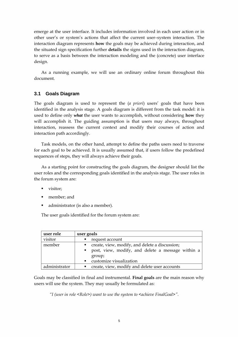
The user goals identified for the forum system are:
user role user goals visitor request account member create, view, modify, and delete a discussion;
post, view, modify, and delete a message within a group;
customize visualization administrator create, view, modify and delete user accounts
Goals may be classified in final and instrumental. Final goals are the main reason why users will use the system. They may usually be formulated as:
“I (user in role <Role>) want to use the system to <achieve FinalGoal>”.
6
Instrumental goals, on the other hand, are used as facilitators to the final goals. In the online forum, the “request account” goal may be considered instrumental, because the user will not want to achieve this goal per se, but only as a means to be able to do more with the system. Goals related to system configuration and customization may also be considered instrumental. Instrumental goals may be further classified into planned and opportunistic . Planned instrumental goals may be formulated as:
“I want to <achieve InstrumentalGoal> to <achieve FinalGoal> more efficiently|easily|...”.
Opportunistic instrumental goals, on the other hand, emerge during interaction, and may be formulated as:
“From where I am now in the system, I want to <formulate and achieve InstrumentalGoal> to <achieve FinalGoal> more efficiently|easily|...”.
In the goals diagram, only final goals and planned instrumental goals are represented. Opportunistic instrumental goals will be identified in the MoLIC diagrams described later.
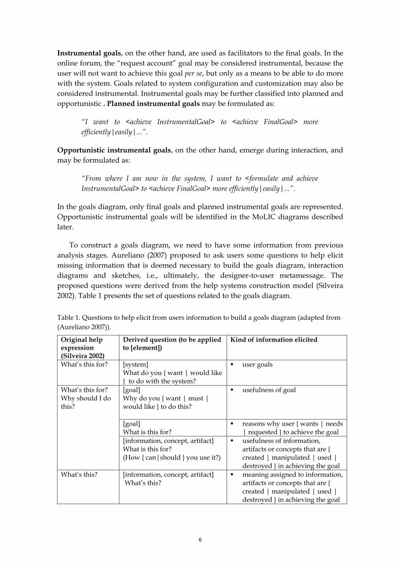
To construct a goals diagram, we need to have some information from previous analysis stages. Aureliano (2007) proposed to ask users some questions to help elicit missing information that is deemed necessary to build the goals diagram, interaction diagrams and sketches, i.e., ultimately, the designer-to-user metamessage. The proposed questions were derived from the help systems construction model (Silveira 2002). Table 1 presents the set of questions related to the goals diagram.
Table 1. Questions to help elicit from users information to build a goals diagram (adapted from (Aureliano 2007)).
Original help expression (Silveira 2002)
Derived question (to be applied to [element])
Kind of information elicited
What’s this for?
[system] What do you { want | would like } to do with the system?
user goals
[goal] Why do you { want | must | would like } to do this?
usefulness of goal
[goal] What is this for?
reasons why user { wants | needs | requested } to achieve the goal
What’s this for? Why should I do this?
[information, concept, artifact] What is this for? (How { can|should } you use it?)
usefulness of information, artifacts or concepts that are { created | manipulated | used | destroyed } in achieving the goal
What’s this? [information, concept, artifact] What’s this?
meaning assigned to information, artifacts or concepts that are { created | manipulated | used | destroyed } in achieving the goal
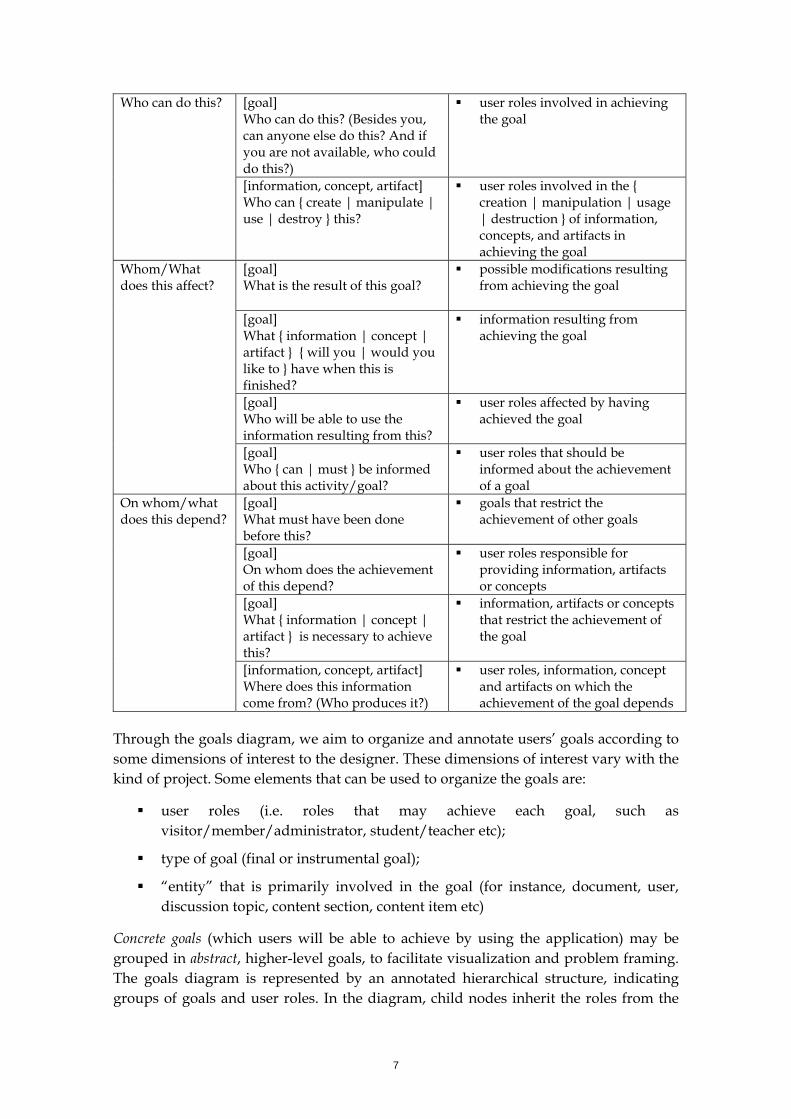
7
[goal] Who can do this? (Besides you, can anyone else do this? And if you are not available, who could do this?)
user roles involved in achieving the goal
Who can do this?
[information, concept, artifact] Who can { create | manipulate | use | destroy } this?
user roles involved in the { creation | manipulation | usage | destruction } of information, concepts, and artifacts in achieving the goal
[goal] What is the result of this goal?
possible modifications resulting from achieving the goal
[goal] What { information | concept | artifact } { will you | would you like to } have when this is finished?
information resulting from achieving the goal
[goal] Who will be able to use the information resulting from this?
user roles affected by having achieved the goal
Whom/What does this affect?
[goal] Who { can | must } be informed about this activity/goal?
user roles that should be informed about the achievement of a goal
[goal] What must have been done before this?
goals that restrict the achievement of other goals
[goal] On whom does the achievement of this depend?
user roles responsible for providing information, artifacts or concepts
[goal] What { information | concept | artifact } is necessary to achieve this?
information, artifacts or concepts that restrict the achievement of the goal
On whom/what does this depend?
[information, concept, artifact] Where does this information come from? (Who produces it?)
user roles, information, concept and artifacts on which the achievement of the goal depends
Through the goals diagram, we aim to organize and annotate users’ goals according to some dimensions of interest to the designer. These dimensions of interest vary with the kind of project. Some elements that can be used to organize the goals are:
user roles (i.e. roles that may achieve each goal, such as visitor/member/administrator, student/teacher etc);
type of goal (final or instrumental goal);
“entity” that is primarily involved in the goal (for instance, document, user, discussion topic, content section, content item etc)
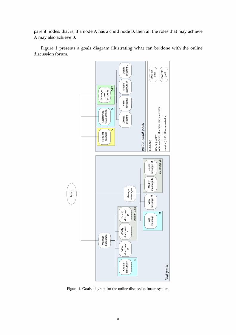
Concrete goals (which users will be able to achieve by using the application) may be grouped in abstract, higher-level goals, to facilitate visualization and problem framing. The goals diagram is represented by an annotated hierarchical structure, indicating groups of goals and user roles. In the diagram, child nodes inherit the roles from the
8
parent nodes, that is, if a node A has a child node B, then all the roles that may achieve A may also achieve B.
Figure 1 presents a goals diagram illustrating what can be done with the online discussion forum.
Figure 1. Goals diagram for the online discussion forum system.
final
goa
ls
crea
tor(
U,M
)
Mod
ify
mes
sage
MD
elet
e m
essa
ge M
crea
tor(
U,D
)
Mod
ify
disc
ussi
on
D
Del
ete
disc
ussi
on
D
inst
rum
enta
l goa
ls
Adm
M
M
LEG
EN
D:
Use
rs’ p
rofil
es:
Adm
= a
dmin
; M =
mem
ber;
V =
visi
tor
crea
tor (
U, X
): U
has
cre
ated
X
V
Foru
m
M
Man
age
disc
ussi
on
Cre
ate
disc
ussi
onM
anag
e m
essa
ges
Pos
t m
essa
ge
Vie
w
disc
ussi
on
D
View
m
essa
ge M
Req
uest
ac
coun
tC
usto
miz
e vi
sual
izat
ion
Man
age
user
ac
coun
ts
Cre
ate
acco
unt
Mod
ify
acco
unt U
Del
ete
acco
unt U
abst
ract
go
al
conc
rete
go
al
Vie
w
acco
unts
9
In the figure, one may note that the final and instrumental goals are separated: the final goals are those directly related to the discussion, while the instrumental (supportive) goals are those related to system configuration and user accounts. Also, some abstract goals are defined to organize concrete goals according to the objects being manipulated. The abstract goals are indicated by dashed lines in the diagram: Manage discussions, Manage messages, Manage user accounts.
Each goal may be associated to one or more scenarios. However, we must keep in mind that, in a scenario-based design approach, possible relationships between goals are often left unrepresented. For instance, let us consider the goals View discussion and Delete discussion illustrated in Figure 1. It may be the case that a scenario for deleting a discussion defines a different set of resources for locating a discussion from the one in the scenario regarding View discussion. This might cause inconsistencies and difficulties in the user–system interaction. An extreme situation would happen if the user views a discussion and then, realizing it should be deleted, he cannot delete it at that moment. Instead, he must abandon the “viewing” activity, select an option to delete the discussion, locate the discussion again, and only then delete it. This example is of course very trivial and rare, but it illustrates a possible inconsistency or inefficient left undetected in using scenarios alone.
As described in the next section, MoLIC interaction diagrams are used to encourage designers to reflect on alternative conversations (which result in alternative courses of actions) for the users to achieve their goals, and to analyze the relationship and interferences between goals. This reflection increases the designer’s chance of preventing the kinds of problems described above from happening.
3.2 Interaction Diagram
As mentioned before, MoLIC diagrams allow designers to represent all the possible interactive conversations users may have with the designer’s deputy during interaction (Paula 2003, Silva 2005). MoLIC was devised to motivate designers in reflecting on the metacommunication, allowing them to specify alternative conversations to the achievement of a given goal, and to analyze the relationship and interferences between goals. Among these interferences we find conversations related to opportunistic instrumental goals.
MoLIC offers a diagrammatic representation that promotes a global view of the application as it will be presented by the designer’s deputy to each user. When there are multiple user roles, we recommend that the user–system interaction of each role be represented in its own MoLIC diagram. This means that, when we say “global view”, we refer to a single user’s perspective of the application (i.e. all the parts of the application he has access to), and not to the whole application spanning multiple roles, as perceived by the designer. We are currently investigating a workflow representation where the MoLIC diagrams for each user role are integrated into a truly global view of the application, a designer’s view of it.
10
The construction of MoLIC diagrams is performed in two steps. First, the designers define the topics of all the possible user–deputy conversations and the user–deputy turn taking that will relate the topics and define all potential conversation flows. This level of abstraction promotes early reflection, analysis and discussions about the interaction solution among members of a multidisciplinary team (Paula et al. 2005). As a second step, later in the design process or during the discussions, as necessary, the interaction is detailed: designers define the signs involved in the communicative exchanges that correspond to each user-system dialogue or individual utterance. The detailed MoLIC diagram is an important resource for designing the concrete user interface at later stages of the development process. The next sections describe the two steps in the construction of MoLIC diagrams.
3.2.1 Topics Definition and Turn-taking: First Step in MoLIC Diagram Construction
In the first step in the construction of MoLIC diagrams, the designers specify all user–system conversations in an interaction diagram. The focus of this step is to support designers in reflecting on general interaction issues, without detailing each interaction step in structures of atomic elements. The general interaction issues involved in the first step are:
user–system turn-taking to achieve a goal;
alternative conversations (interaction paths) for users to achieve the same goal (possibly addressing the needs and preferences of different users profiles);
conversations related to opportunistic instrumental goals;
mechanisms for breakdown recovery;
the (in)consistency between similar or analogous interaction paths.
We recommend designers to build one MoLIC diagram per user role. Each diagram represents the whole view users in that role will have of the system. There are, of course, cases where two or more roles will have such similar interactions (i.e., they share so many elements and structure of MoLIC diagrams) that a single MoLIC diagram is used for multiple roles.
In order for a user to achieve a goal, they must “talk” to the designer’s deputy about what they want to accomplish (and how the deputy allows, recommends or requires that they do it). Therefore, both user and designer’s deputy take turns in conversational exchanges while the user moves toward the achievement of his goals. It is important to note that this communicative perspective does not imply that the concrete user interface will have to be conversational. It only means that the communicative issues involved in user-system interaction are brought to focus and explicitly addressed during interaction design.
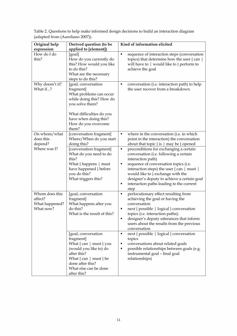
As with the goals diagram, Aureliano (2007) proposed a set of questions to help elicit from users information necessary for the design decisions related to the interaction design. (Table 2).
11
Table 2. Questions to help make informed design decisions to build an interaction diagram (adapted from (Aureliano 2007)).
Original help expression
Derived question (to be applied to [element])
Kind of information elicited
How do I do this?
[goal] How do you currently do this? How would you like to do this? What are the necessary steps to do this?
sequence of interaction steps (conversation topics) that determine how the user { can | will have to | would like to } perform to achieve the goal
Why doesn’t it? What if...?
[goal, conversation fragment] What problems can occur while doing this? How do you solve them? What difficulties do you have when doing this? How do you overcome them?
conversation (i.e. interaction path) to help the user recover from a breakdown
[conversation fragment] Where/When do you start doing this?
where in the conversation (i.e. in which point in the interaction) the conversation about that topic { is | may be } opened
On whom/what does this depend? Where was I? [conversation fragment]
What do you need to do this? What { happens | must have happened } before you do this? What triggers this?
preconditions for exchanging a certain conversation (i.e. following a certain interaction path)
sequence of conversation topics (i.e. interaction steps) the user { can | must | would like to } exchange with the designer’s deputy to achieve a certain goal
interaction paths leading to the current step
[goal, conversation fragment] What happens after you do this? What is the result of this?
perlocutionary effect resulting from achieving the goal or having the conversation
next { possible | logical } conversation topics (i.e. interaction paths);
designer’s deputy utterances that inform users about the results from the previous conversation
Whom does this affect? What happened? What now?
[goal, conversation fragment] What { can | must } you (would you like to) do after this? What { can | must } be done after this? What else can be done after this?
next { possible | logical } conversation topics
conversations about related goals possible relationships between goals (e.g.
instrumental goal – final goal relationships)
12
Oops! [goal, conversation fragment] How can you cancel this? How can you undo it? How can you revert its effect?
exchanges necessary to abort the current conversation
conversation necessary to undo or revert a previous conversation fragment
Is there another way to do this? What if...?
[goal, conversation fragment] { Do you | Would you like to } do this in some other way? What if you tried to do this in some other way, how would it be?
alternative conversations to achieve the same goal
relationship between goals that cause for conversation topic shifts between them (i.e. inserted sequences or deviations in the conversation)
Where is...? [information, concept, artifact] Where is this information { created | used | manipulated | destroyed }?
where in the conversation is a certain information, concept or artifact { created | used | manipulated | destroyed }
In the next sections, we will explore various aspects of the user-deputy conversation.
How does conversation start? And how does it end?
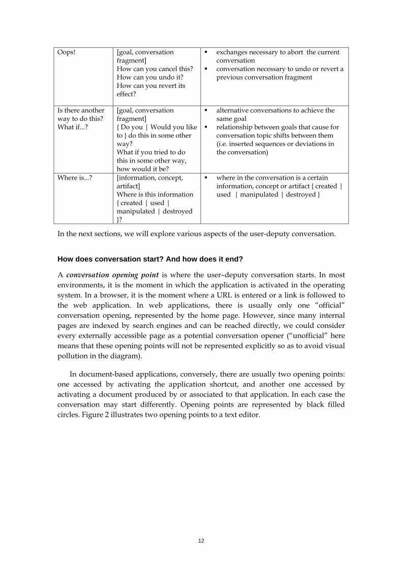
A conversation opening point is where the user–deputy conversation starts. In most environments, it is the moment in which the application is activated in the operating system. In a browser, it is the moment where a URL is entered or a link is followed to the web application. In web applications, there is usually only one “official” conversation opening, represented by the home page. However, since many internal pages are indexed by search engines and can be reached directly, we could consider every externally accessible page as a potential conversation opener (“unofficial” here means that these opening points will not be represented explicitly so as to avoid visual pollution in the diagram).
In document-based applications, conversely, there are usually two opening points: one accessed by activating the application shortcut, and another one accessed by activating a document produced by or associated to that application. In each case the conversation may start differently. Opening points are represented by black filled circles. Figure 2 illustrates two opening points to a text editor.
13
opening point opening point
Figure 2. Conversation opening points for a text editor, by activating the application with a blank document and by activating the application with an existing document.
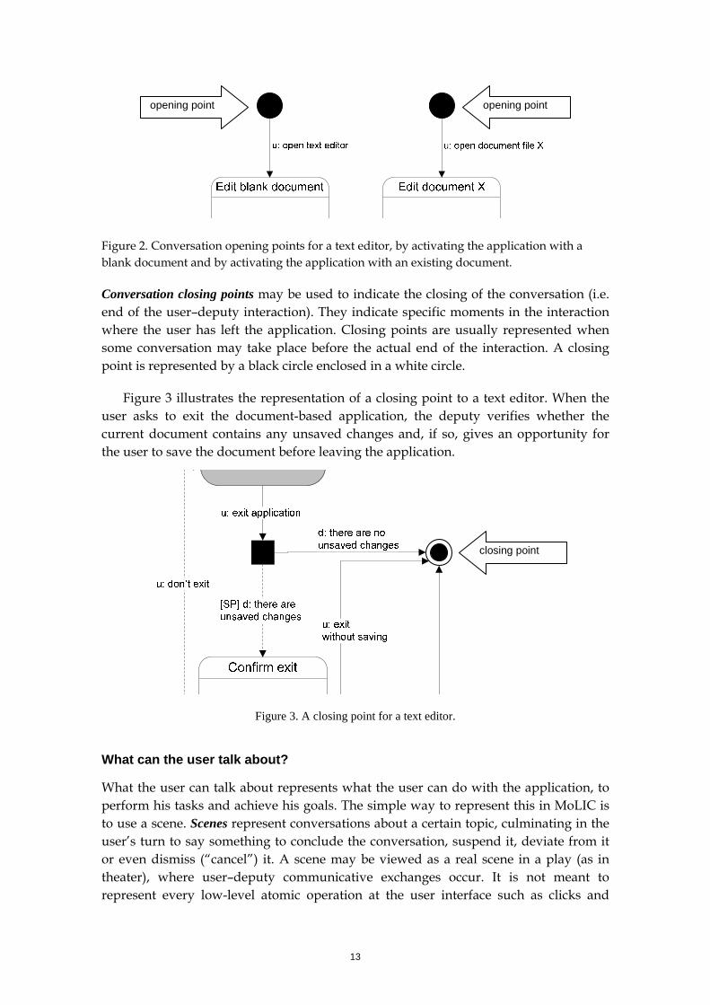
Conversation closing points may be used to indicate the closing of the conversation (i.e. end of the user–deputy interaction). They indicate specific moments in the interaction where the user has left the application. Closing points are usually represented when some conversation may take place before the actual end of the interaction. A closing point is represented by a black circle enclosed in a white circle.
Figure 3 illustrates the representation of a closing point to a text editor. When the user asks to exit the document-based application, the deputy verifies whether the current document contains any unsaved changes and, if so, gives an opportunity for the user to save the document before leaving the application.
closing point
Figure 3. A closing point for a text editor.
What can the user talk about?
What the user can talk about represents what the user can do with the application, to perform his tasks and achieve his goals. The simple way to represent this in MoLIC is to use a scene. Scenes represent conversations about a certain topic, culminating in the user’s turn to say something to conclude the conversation, suspend it, deviate from it or even dismiss (“cancel”) it. A scene may be viewed as a real scene in a play (as in theater), where user–deputy communicative exchanges occur. It is not meant to represent every low-level atomic operation at the user interface such as clicks and
14
types. Instead, the level of abstraction we are looking for is that of topics, subtopics and focus in a conversation.
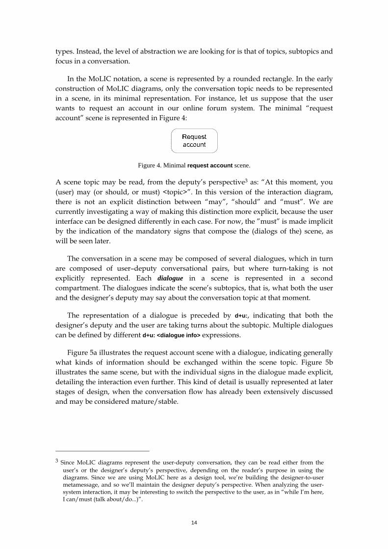
In the MoLIC notation, a scene is represented by a rounded rectangle. In the early construction of MoLIC diagrams, only the conversation topic needs to be represented in a scene, in its minimal representation. For instance, let us suppose that the user wants to request an account in our online forum system. The minimal “request account” scene is represented in Figure 4:
Figure 4. Minimal request account scene.
A scene topic may be read, from the deputy’s perspective3 as: “At this moment, you (user) may (or should, or must) <topic>”. In this version of the interaction diagram, there is not an explicit distinction between “may”, “should” and “must”. We are currently investigating a way of making this distinction more explicit, because the user interface can be designed differently in each case. For now, the ”must” is made implicit by the indication of the mandatory signs that compose the (dialogs of the) scene, as will be seen later.
The conversation in a scene may be composed of several dialogues, which in turn are composed of user–deputy conversational pairs, but where turn-taking is not explicitly represented. Each dialogue in a scene is represented in a second compartment. The dialogues indicate the scene’s subtopics, that is, what both the user and the designer’s deputy may say about the conversation topic at that moment.
The representation of a dialogue is preceded by d+u:, indicating that both the designer’s deputy and the user are taking turns about the subtopic. Multiple dialogues can be defined by different d+u: <dialogue info> expressions.
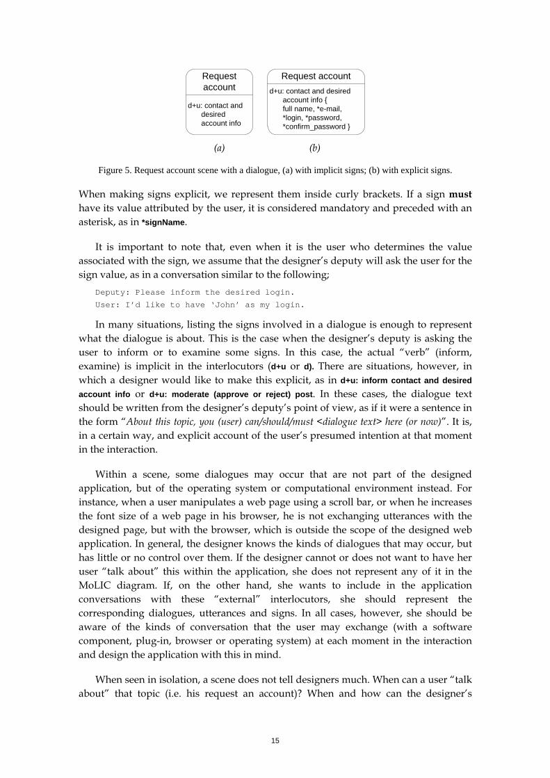
Figure 5a illustrates the request account scene with a dialogue, indicating generally what kinds of information should be exchanged within the scene topic. Figure 5b illustrates the same scene, but with the individual signs in the dialogue made explicit, detailing the interaction even further. This kind of detail is usually represented at later stages of design, when the conversation flow has already been extensively discussed and may be considered mature/stable.
3 Since MoLIC diagrams represent the user-deputy conversation, they can be read either from the
user’s or the designer’s deputy’s perspective, depending on the reader’s purpose in using the diagrams. Since we are using MoLIC here as a design tool, we’re building the designer-to-user metamessage, and so we’ll maintain the designer deputy’s perspective. When analyzing the user-system interaction, it may be interesting to switch the perspective to the user, as in “while I’m here, I can/must (talk about/do...)”.
15
Request account
d+u: contact and desired account info
Request accountd+u: contact and desired
account info { full name, *e-mail, *login, *password, *confirm_password }
(a) (b)
Figure 5. Request account scene with a dialogue, (a) with implicit signs; (b) with explicit signs.
When making signs explicit, we represent them inside curly brackets. If a sign must have its value attributed by the user, it is considered mandatory and preceded with an asterisk, as in *signName.
It is important to note that, even when it is the user who determines the value associated with the sign, we assume that the designer’s deputy will ask the user for the sign value, as in a conversation similar to the following;
Deputy: Please inform the desired login.
User: I’d like to have ‘John’ as my login.
In many situations, listing the signs involved in a dialogue is enough to represent what the dialogue is about. This is the case when the designer’s deputy is asking the user to inform or to examine some signs. In this case, the actual “verb” (inform, examine) is implicit in the interlocutors (d+u or d). There are situations, however, in which a designer would like to make this explicit, as in d+u: inform contact and desired account info or d+u: moderate (approve or reject) post. In these cases, the dialogue text should be written from the designer’s deputy’s point of view, as if it were a sentence in the form “About this topic, you (user) can/should/must <dialogue text> here (or now)”. It is, in a certain way, and explicit account of the user’s presumed intention at that moment in the interaction.
Within a scene, some dialogues may occur that are not part of the designed application, but of the operating system or computational environment instead. For instance, when a user manipulates a web page using a scroll bar, or when he increases the font size of a web page in his browser, he is not exchanging utterances with the designed page, but with the browser, which is outside the scope of the designed web application. In general, the designer knows the kinds of dialogues that may occur, but has little or no control over them. If the designer cannot or does not want to have her user “talk about” this within the application, she does not represent any of it in the MoLIC diagram. If, on the other hand, she wants to include in the application conversations with these “external” interlocutors, she should represent the corresponding dialogues, utterances and signs. In all cases, however, she should be aware of the kinds of conversation that the user may exchange (with a software component, plug-in, browser or operating system) at each moment in the interaction and design the application with this in mind.
When seen in isolation, a scene does not tell designers much. When can a user “talk about” that topic (i.e. his request an account)? When and how can the designer’s
16
deputy respond to what the user has said? What is the result (i.e. the changes in the system or in the “real world”) of this conversation exchange (i.e. what does the user accomplish)? Can something go wrong? If so, what, and how can the user recover from it and proceed to achieving his goal? What is the correspondence between a MoLIC diagram and the goals diagram? The MoLIC elements that allow designers to address these issues are seen next.
What now? When and how can the designer’s deputy respond to what the user has said?
When the user is done talking about the current topic, and in order for the designer’s deputy to respond to the communicative exchanges represented in the scene, he needs to give the turn to the designer’s deputy, which will “think about” (i.e. process) the user’s communication and respond accordingly. Two MoLIC elements are used here: a transition utterance (or turn-taking utterance) and a system process.
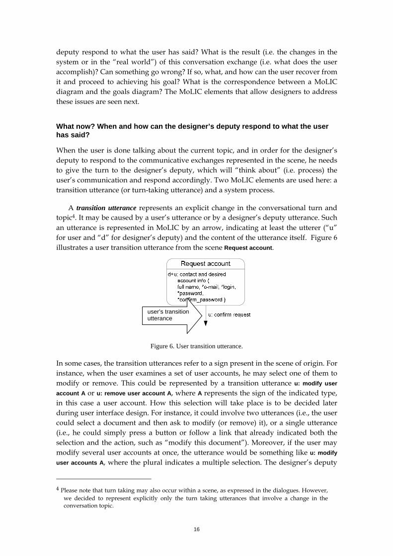
A transition utterance represents an explicit change in the conversational turn and topic4. It may be caused by a user’s utterance or by a designer’s deputy utterance. Such an utterance is represented in MoLIC by an arrow, indicating at least the utterer (“u” for user and “d” for designer’s deputy) and the content of the utterance itself. Figure 6 illustrates a user transition utterance from the scene Request account.
user’s transition utterance
Figure 6. User transition utterance.
In some cases, the transition utterances refer to a sign present in the scene of origin. For instance, when the user examines a set of user accounts, he may select one of them to modify or remove. This could be represented by a transition utterance u: modify user account A or u: remove user account A, where A represents the sign of the indicated type, in this case a user account. How this selection will take place is to be decided later during user interface design. For instance, it could involve two utterances (i.e., the user could select a document and then ask to modify (or remove) it), or a single utterance (i.e., he could simply press a button or follow a link that already indicated both the selection and the action, such as “modify this document”). Moreover, if the user may modify several user accounts at once, the utterance would be something like u: modify user accounts A, where the plural indicates a multiple selection. The designer’s deputy
4 Please note that turn taking may also occur within a scene, as expressed in the dialogues. However,
we decided to represent explicitly only the turn taking utterances that involve a change in the conversation topic.
17
may also emit utterances that refer to manipulated signs, especially in the case of a breakdown. For instance, the utterance d: invalid e-mail for user X.
What happened? What is the result (i.e. the changes in the system or in the “real world”) of this conversation exchange (i.e. what does the user accomplish)?
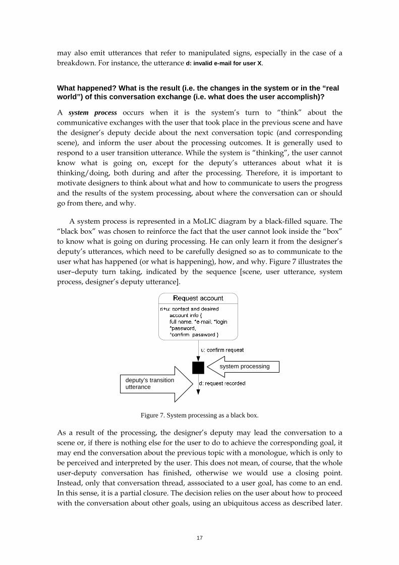
A system process occurs when it is the system’s turn to “think” about the communicative exchanges with the user that took place in the previous scene and have the designer’s deputy decide about the next conversation topic (and corresponding scene), and inform the user about the processing outcomes. It is generally used to respond to a user transition utterance. While the system is “thinking”, the user cannot know what is going on, except for the deputy’s utterances about what it is thinking/doing, both during and after the processing. Therefore, it is important to motivate designers to think about what and how to communicate to users the progress and the results of the system processing, about where the conversation can or should go from there, and why.
A system process is represented in a MoLIC diagram by a black-filled square. The “black box” was chosen to reinforce the fact that the user cannot look inside the “box” to know what is going on during processing. He can only learn it from the designer’s deputy’s utterances, which need to be carefully designed so as to communicate to the user what has happened (or what is happening), how, and why. Figure 7 illustrates the user–deputy turn taking, indicated by the sequence [scene, user utterance, system process, designer’s deputy utterance].
deputy’s transition utterance
system processing
Figure 7. System processing as a black box.
As a result of the processing, the designer’s deputy may lead the conversation to a scene or, if there is nothing else for the user to do to achieve the corresponding goal, it may end the conversation about the previous topic with a monologue, which is only to be perceived and interpreted by the user. This does not mean, of course, that the whole user-deputy conversation has finished, otherwise we would use a closing point. Instead, only that conversation thread, asssociated to a user goal, has come to an end. In this sense, it is a partial closure. The decision relies on the user about how to proceed with the conversation about other goals, using an ubiquitous access as described later.
18
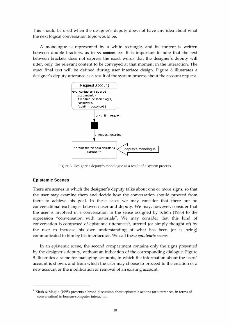
This should be used when the designer’s deputy does not have any idea about what the next logical conversation topic would be.
A monologue is represented by a white rectangle, and its content is written between double brackets, as in << content >>. It is important to note that the text between brackets does not express the exact words that the designer’s deputy will utter, only the relevant content to be conveyed at that moment in the interaction. The exact final text will be defined during user interface design. Figure 8 illustrates a designer’s deputy utterance as a result of the system process about the account request.
deputy’s monologue
Figure 8. Designer’s deputy’s monologue as a result of a system process.
Epistemic Scenes
There are scenes in which the designer’s deputy talks about one or more signs, so that the user may examine them and decide how the conversation should proceed from there to achieve his goal. In these cases we may consider that there are no conversational exchanges between user and deputy. We may, however, consider that the user is involved in a conversation in the sense assigned by Schön (1983) to the expression “conversation with materials”. We may consider that this kind of conversation is composed of epistemic utterances5, uttered (or simply thought of) by the user to increase his own understanding of what has been (or is being) communicated to him by his interlocutor. We call these epistemic scenes.
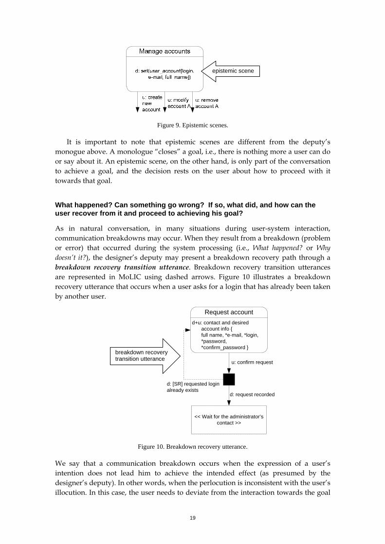
In an epistemic scene, the second compartment contains only the signs presented by the designer’s deputy, without an indication of the corresponding dialogue. Figure 9 illustrates a scene for managing accounts, in which the information about the users’ account is shown, and from which the user may choose to proceed to the creation of a new account or the modification or removal of an existing account.
5 Kirsh & Maglio (1995) presents a broad discussion about epistemic actions (or utterances, in terms of
conversation) in human-computer interaction.
19
epistemic scene
Figure 9. Epistemic scenes.
It is important to note that epistemic scenes are different from the deputy’s monogue above. A monologue “closes” a goal, i.e., there is nothing more a user can do or say about it. An epistemic scene, on the other hand, is only part of the conversation to achieve a goal, and the decision rests on the user about how to proceed with it towards that goal.
What happened? Can something go wrong? If so, what did, and how can the user recover from it and proceed to achieving his goal?
As in natural conversation, in many situations during user-system interaction, communication breakdowns may occur. When they result from a breakdown (problem or error) that occurred during the system processing (i.e., What happened? or Why doesn’t it?), the designer’s deputy may present a breakdown recovery path through a breakdown recovery transition utterance. Breakdown recovery transition utterances are represented in MoLIC using dashed arrows. Figure 10 illustrates a breakdown recovery utterance that occurs when a user asks for a login that has already been taken by another user.
Request accountd+u: contact and desired
account info { full name, *e-mail, *login, *password, *confirm_password }
u: confirm request
d: request recorded
d: [SR] requested login already exists
<< Wait for the administrator’s contact >>
breakdown recovery transition utterance
Figure 10. Breakdown recovery utterance.
We say that a communication breakdown occurs when the expression of a user’s intention does not lead him to achieve the intended effect (as presumed by the designer’s deputy). In other words, when the perlocution is inconsistent with the user’s illocution. In this case, the user needs to deviate from the interaction towards the goal
20
to be achieved to seek an understanding of the interaction itself, that is, about how to express his intention in a way that the designer’s deputy may “understand” it (i.e. process it towards the successful achievement of the goal as designed to match the user’s presumed intention).
Since it is natural and frequent that misunderstandings occur in a conversation, semiotic engineering underscores the importance of representing communicative breakdowns that may occur during interaction. Besides attempting to anticipate and avoid breakdowns, it is necessary to define the way in which the deputy will communicate to the user that a breakdown has occurred and to support him in recovering from the problem, i.e., how the user will proceed with the conversation towards the achievement of his goal. Therefore, for each moment of interaction in which a breakdown may be anticipated, the designer should define the breakdown recovery (or prevention) utterances, and also the breakdown recovery mechanisms offered to users.
Breakdown prevention and recovery mechanisms
One may note the [SR] prefix in Figure 10. This indicates the kind of mechanism offered to users for recovering from the breakdown. Some mechanisms are represented within transition utterances, whereas others are associated to signs in the conceptual sign schema.
This may be one of the following (Paula & Barbosa 2003):
Breakdown prevention mechanisms
PP – passive prevention: breakdowns that may be prevented by documentation or explicit online instructions. For instance, tips such as “(dd/mm/yyyy)” next to a date field or instructions such as “at least two forms of contact must be provided”.
AP – active prevention: breakdowns that may be actively avoided by the system, preventing the user ‘s expression, restricting it to valid illocutions. This may be designed in the user interface, for instance, by offering a calendar control for users to select a date instead of letting them type it in, by preventing users from typing letters or symbols in a numeric field, by preventing the user from typing in more than N characters in an entry field or by activating and deactivating buttons and links according to the application’s current status.
SP – supported prevention: situations that the designer’s deputy detects as being a potential breakdown, but whose final decision relies on the user. It is up to the designer’s deputy to adequately describe the situation and ask the user to take an informed decision about the future directions of the interaction. This may occur, for instance, when the user expresses an intention to save a file with a different name (“Save as...”) but informs a name of an existing file. This kind of support is usually designed at the user interface as confirmation messages, such as “File ‘file name’ already exists. What would you like to do? ( ) replace existing file; ( ) inform another name for the file; ( ) cancel the save operation”.
21
Breakdown recovery mechanisms
SR – supported recovery: breakdowns that need to be resolved by the user with some support from the designer’s deputy, that is, the deputy’s illocutions should help the user to understand what happened and to know what illocutions will allow him to achieve the intended perlocution and proceed towards his goal. For instance, when the user informs an invalid piece of data, the designer’s deputy should communicate the error and offer an opportunity for the user to correct the data. In MoLIC diagrams, this mechanism is usually represented by a designer’s deputy utterance returning to the scene where the user made the mistake, as illustrated in Figure 10 above.
EC – error capture: situations where the breakdown was not caused by a communicative problem, but by a system error. When the designer’s deputy is capable of identifying system errors, it should notify the user and, if possible, suggest ways of recovering from the problem. However, an error capture indicates that the remedial conversation will take place outside of the application. For instance, when a file is corrupted and cannot be opened, the designer’s deputy could, in addition to describing the problem, suggest that the user copy the file again from its original location. This is usually represented by a transition utterance leading to a designer’s deputy monologue.
It is important to note that not all breakdown recovery utterances are emitted by the designer’s deputy. When uttered by a user, it represents an explicitly designed opportunity for the user to recover from and unintended or misguided interaction path. Such utterances could be read as “Oops! This is not what I intended to do”. In this case, we do not represent any breakdown recovery “mechanism”, but only have a dashed arrow with a user utterance, as in ”u: cancel editing document”.
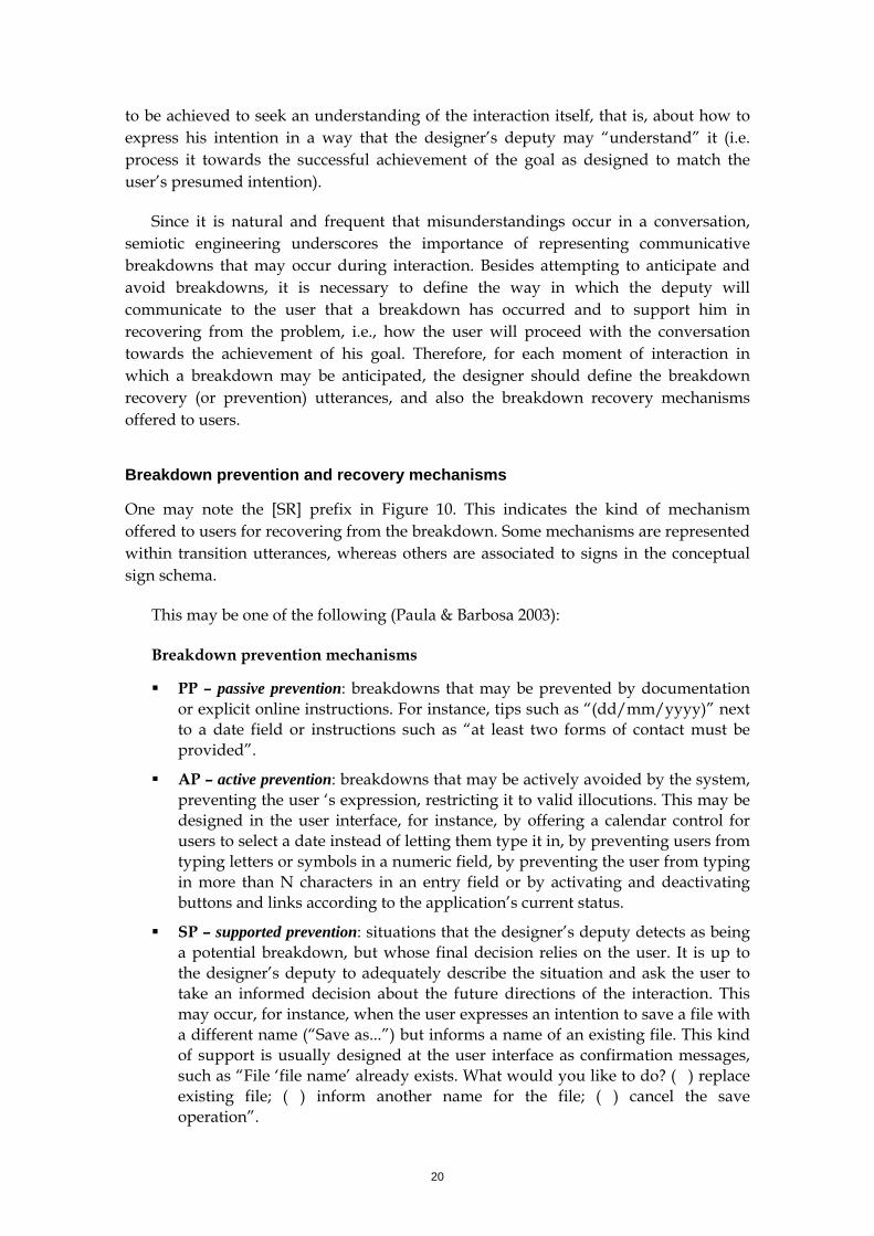
What’s going on? Synchronous communication about ongoing system processes
In the diagram fragments seen so far, the result of the processing is only communicated after the process is concluded, via a designer’s deputy’s utterance. For some processes, however, the designer may want to communicate to users also the intermediate states or progress of the processing, during the processing and not after it. This synchronous communication becomes more important as the process increases in duration, for instance, when a file download is taking place, or when a file is being search in the hard drive. In these cases, the designer’s deputy may emit several utterances during the system’s processing. To represent this kind of communication, we draw a white rectangle next to the system process black box, which represents synchronized utterances about the system process. Figure 11 illustrates this kind of element.
22
synchronous communication about ongoing process
Figure 11. Synchronous communication about the progress of an ongoing system process.
It is important to ensure that the communication about a process be an indication (or an index, in semiotic terms) of the processing state. This means that there must be a causal relation between the content that is communicated and the semantics of the processing.
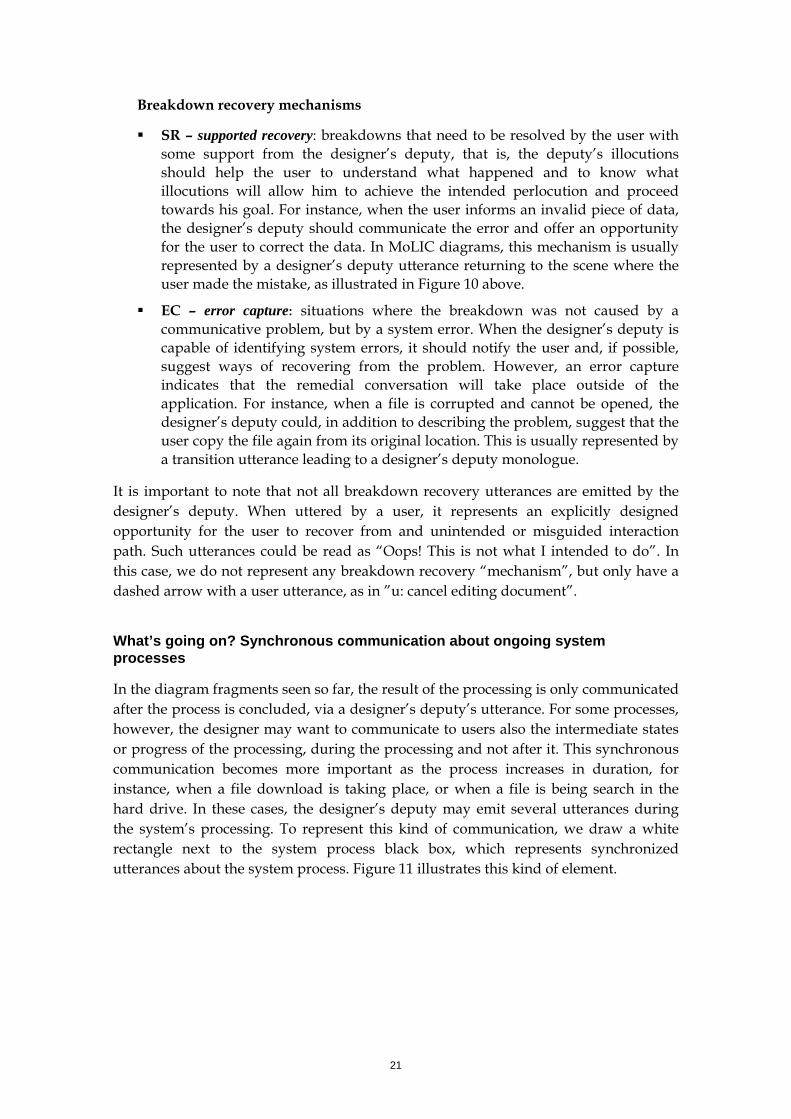
In addition, by making the user aware of the progress of an ongoing process, the designer now should be able to yield to the user some control over the processing, such as suspending or cancelling it. Therefore, users’ utterances may spring from the “white box”, as in Figure 12.
Figure 12. User transition utterance to abandon an ongoing process.
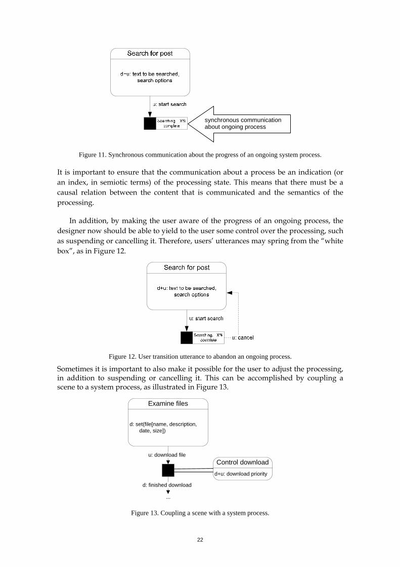
Sometimes it is important to also make it possible for the user to adjust the processing, in addition to suspending or cancelling it. This can be accomplished by coupling a scene to a system process, as illustrated in Figure 13.
Control downloadd+u: download priority
Examine files
d: set(file[name, description, date, size])
u: download file
d: finished download
...
Figure 13. Coupling a scene with a system process.
23
What now? When can a user “talk about” a topic (i.e. exchange a conversation about a topic)?
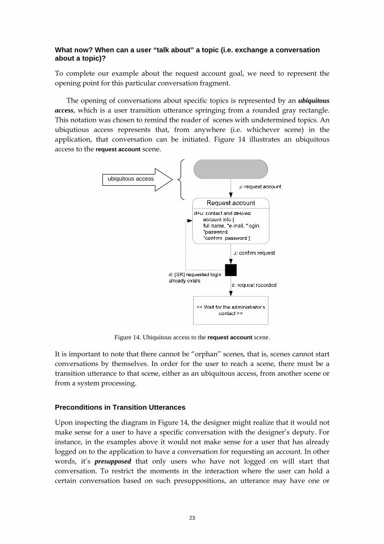
To complete our example about the request account goal, we need to represent the opening point for this particular conversation fragment.
The opening of conversations about specific topics is represented by an ubiquitous access, which is a user transition utterance springing from a rounded gray rectangle. This notation was chosen to remind the reader of scenes with undetermined topics. An ubiqutious access represents that, from anywhere (i.e. whichever scene) in the application, that conversation can be initiated. Figure 14 illustrates an ubiquitous access to the request account scene.
ubiquitous access
Figure 14. Ubiquitous access to the request account scene.
It is important to note that there cannot be “orphan” scenes, that is, scenes cannot start conversations by themselves. In order for the user to reach a scene, there must be a transition utterance to that scene, either as an ubiquitous access, from another scene or from a system processing.
Preconditions in Transition Utterances
Upon inspecting the diagram in Figure 14, the designer might realize that it would not make sense for a user to have a specific conversation with the designer’s deputy. For instance, in the examples above it would not make sense for a user that has already logged on to the application to have a conversation for requesting an account. In other words, it’s presupposed that only users who have not logged on will start that conversation. To restrict the moments in the interaction where the user can hold a certain conversation based on such presuppositions, an utterance may have one or
24
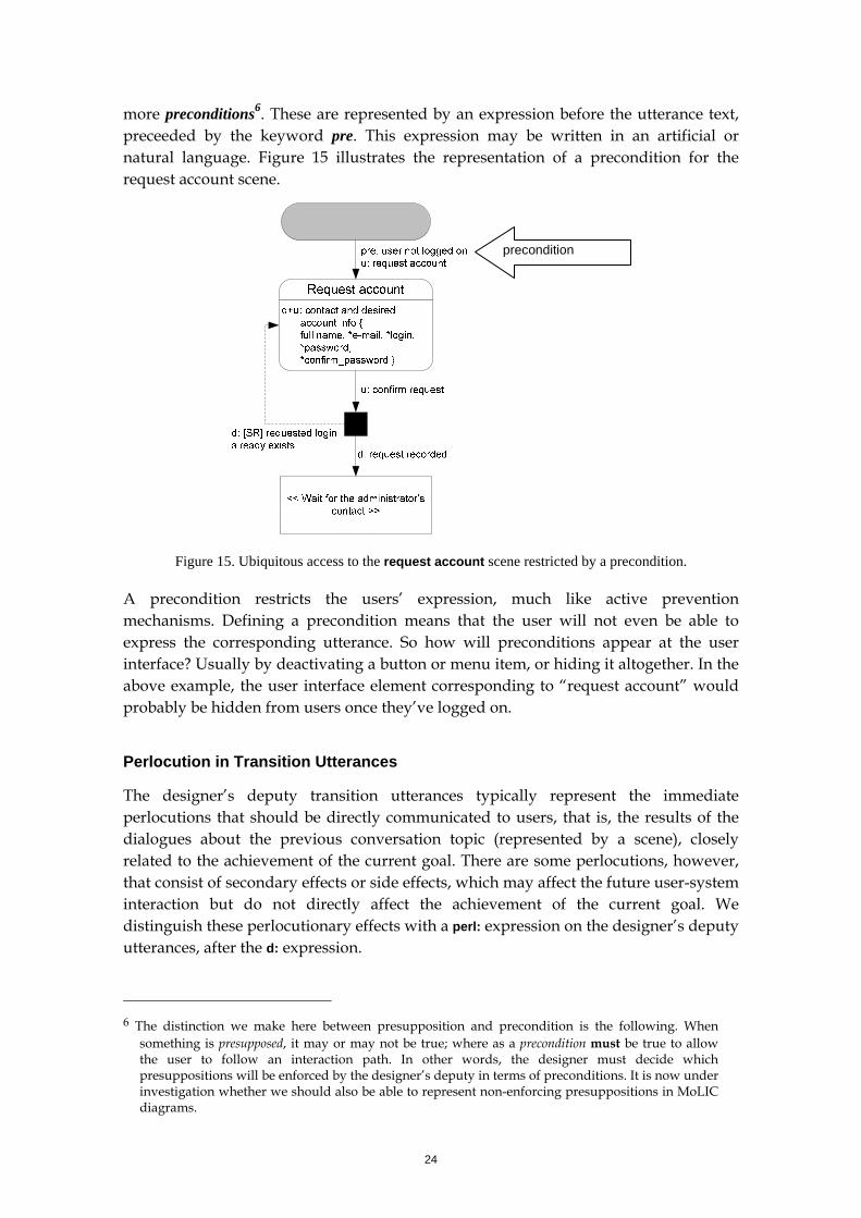
more preconditions6. These are represented by an expression before the utterance text, preceeded by the keyword pre. This expression may be written in an artificial or natural language. Figure 15 illustrates the representation of a precondition for the request account scene.
precondition
Figure 15. Ubiquitous access to the request account scene restricted by a precondition.
A precondition restricts the users’ expression, much like active prevention mechanisms. Defining a precondition means that the user will not even be able to express the corresponding utterance. So how will preconditions appear at the user interface? Usually by deactivating a button or menu item, or hiding it altogether. In the above example, the user interface element corresponding to “request account” would probably be hidden from users once they’ve logged on.
Perlocution in Transition Utterances
The designer’s deputy transition utterances typically represent the immediate perlocutions that should be directly communicated to users, that is, the results of the dialogues about the previous conversation topic (represented by a scene), closely related to the achievement of the current goal. There are some perlocutions, however, that consist of secondary effects or side effects, which may affect the future user-system interaction but do not directly affect the achievement of the current goal. We distinguish these perlocutionary effects with a perl: expression on the designer’s deputy utterances, after the d: expression.
6 The distinction we make here between presupposition and precondition is the following. When
something is presupposed, it may or may not be true; where as a precondition must be true to allow the user to follow an interaction path. In other words, the designer must decide which presuppositions will be enforced by the designer’s deputy in terms of preconditions. It is now under investigation whether we should also be able to represent non-enforcing presuppositions in MoLIC diagrams.
25
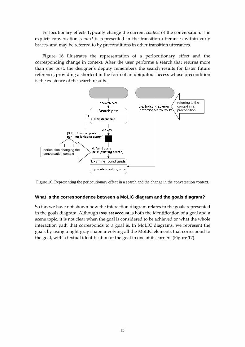
Perlocutionary effects typically change the current context of the conversation. The explicit conversation context is represented in the transition utterances within curly braces, and may be referred to by preconditions in other transition utterances.
Figure 16 illustrates the representation of a perlocutionary effect and the corresponding change in context. After the user performs a search that returns more than one post, the designer’s deputy remembers the search results for faster future reference, providing a shortcut in the form of an ubiquitous access whose precondition is the existence of the search results.
referring to the context in a precondition
perlocution changing the conversation context
Figure 16. Representing the perlocutionary effect in a search and the change in the conversation context.
What is the correspondence between a MoLIC diagram and the goals diagram?
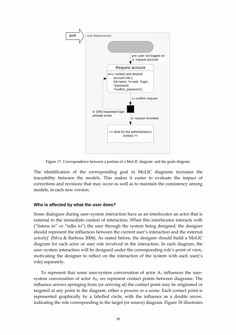
So far, we have not shown how the interaction diagram relates to the goals represented in the goals diagram. Although Request account is both the identification of a goal and a scene topic, it is not clear when the goal is considered to be achieved or what the whole interaction path that corresponds to a goal is. In MoLIC diagrams, we represent the goals by using a light gray shape involving all the MoLIC elements that correspond to the goal, with a textual identification of the goal in one of its corners (Figure 17).
26
Goal: Request account
Request accountd+u: contact and desired
account info { full name, *e-mail, *login, *password, *confirm_password }
u: confirm request
d: request recorded
d: [SR] requested login already exists
pre: user not logged onu: request account
<< Wait for the administrator’s contact >>
goal
Figure 17. Correspondence between a portion of a MoLIC diagram and the goals diagram.
The identification of the corresponding goal in MoLIC diagrams increases the traceability between the models. This makes it easier to evaluate the impact of corrections and revisions that may occur as well as to maintain the consistency among models, in each new version.
Who is affected by what the user does?
Some dialogues during user–system interaction have as an interlocutor an actor that is external to the immediate context of interaction. When this interlocutor interacts with (“listens to” or “talks to”) the user through the system being designed, the designer should represent the influences between the current user’s interaction and the external actor(s)’ (Silva & Barbosa 2004). As stated before, the designer should build a MoLIC diagram for each actor or user role involved in the interaction. In each diagram, the user–system interaction will be designed under the corresponding role’s point of view, motivating the designer to reflect on the interaction of the system with each user(‘s role) separately.
To represent that some user-system conversation of actor A1 influences the user-system conversation of actor A2, we represent contact points between diagrams. The influence arrows springing from (or arriving at) the contact point may be originated or targeted at any point in the diagram, either a process or a scene. Each contact point is represented graphically by a labelled circle, with the influence as a double arrow, indicating the role corresponding to the target (or source) diagram. Figure 18 illustrates
27
the contact points designed into a publishing application, in which an author writes a text and submits for the editor to approve it or to send it back to the author for revision.
Figure 18. Contact point between two MoLIC diagrams.
What is affected by the interaction?
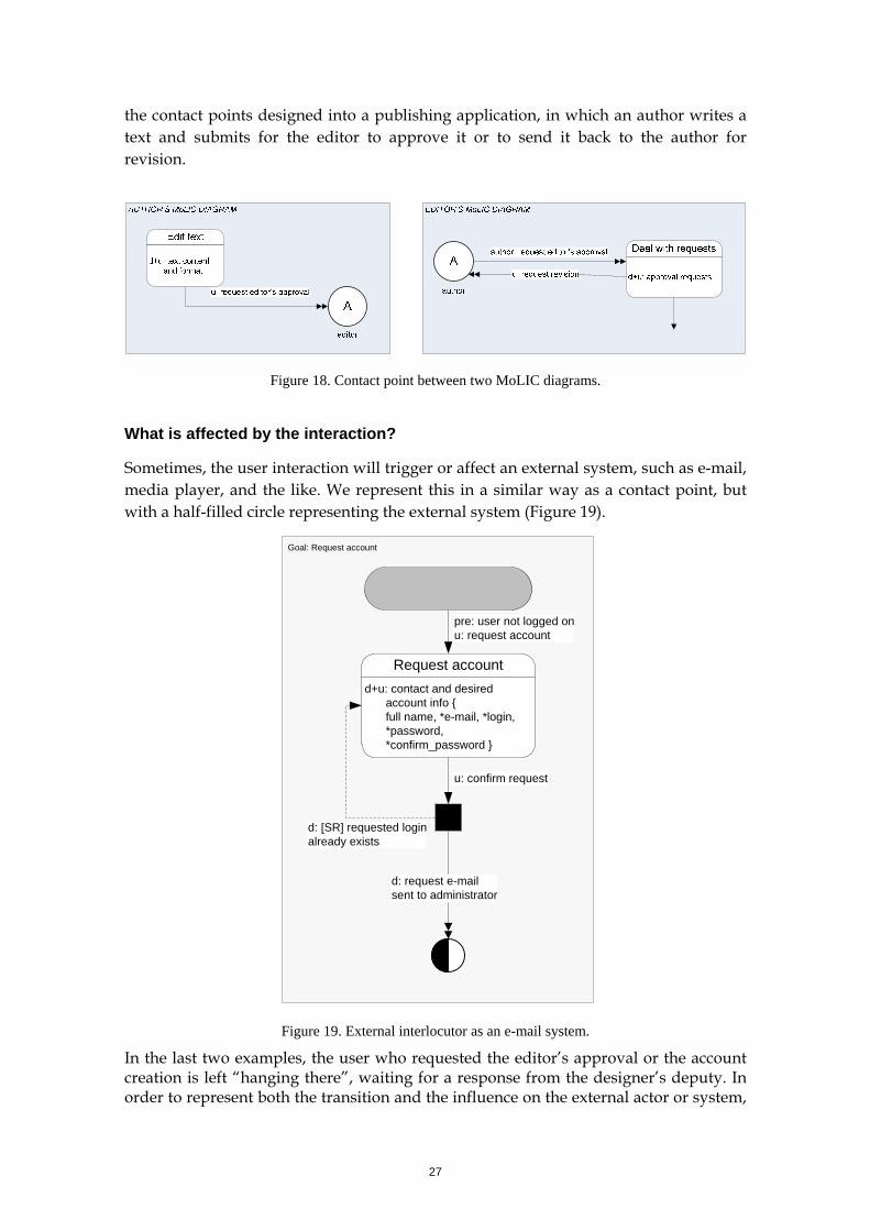
Sometimes, the user interaction will trigger or affect an external system, such as e-mail, media player, and the like. We represent this in a similar way as a contact point, but with a half-filled circle representing the external system (Figure 19).
Goal: Request account
Request accountd+u: contact and desired
account info { full name, *e-mail, *login, *password, *confirm_password }
u: confirm request
d: [SR] requested login already exists
pre: user not logged onu: request account
d: request e-mail sent to administrator
Figure 19. External interlocutor as an e-mail system.
In the last two examples, the user who requested the editor’s approval or the account creation is left “hanging there”, waiting for a response from the designer’s deputy. In order to represent both the transition and the influence on the external actor or system,
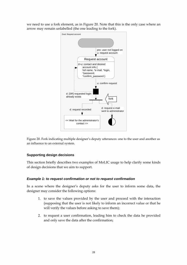
28
we need to use a fork element, as in Figure 20. Note that this is the only case where an arrow may remain unlabelled (the one leading to the fork).
Goal: Request account
Request accountd+u: contact and desired
account info { full name, *e-mail, *login, *password, *confirm_password }
u: confirm request
d: [SR] requested login already exists
pre: user not logged onu: request account
d: request e-mail sent to administrator
<< Wait for the administrator’s contact >>
d: request recorded
fork
Figure 20. Fork indicating multiple designer’s deputy utterances: one to the user and another as an influence to an external system.
Supporting design decisions
This section briefly describes two examples of MoLIC usage to help clarify some kinds of design decisions that we aim to support.
Example 1: to request confirmation or not to request confirmation
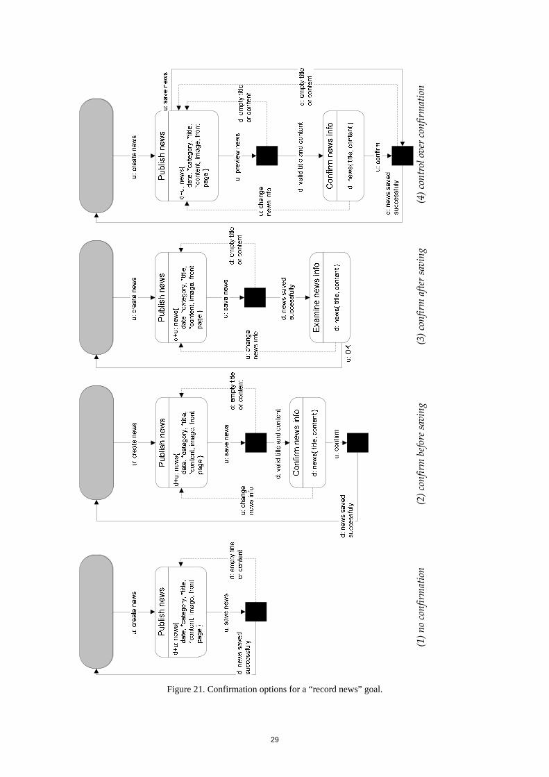
In a scene where the designer’s deputy asks for the user to inform some data, the designer may consider the following options:
1. to save the values provided by the user and proceed with the interaction (supposing that the user is not likely to inform an incorrect value or that he will verify the values before asking to save them);
2. to request a user confirmation, leading him to check the data he provided and only save the data after the confirmation;
29
(4) c
ontr
ol o
ver c
onfir
mat
ion
(3) c
onfir
m a
fter s
avin
g
(2) c
onfir
m b
efore
savi
ng
(1) n
o co
nfirm
atio
n
Figure 21. Confirmation options for a “record news” goal.
30
3. to save the data but, instead of proceeding with the interaction, to show the saved data so as to give to the user a chance to correct the values, if necessary;
4. to give control to the user about the confirmation, allowing him to preview the information before confirming or to save it immediately.
Figure 21 illustrates these options, from left to right.
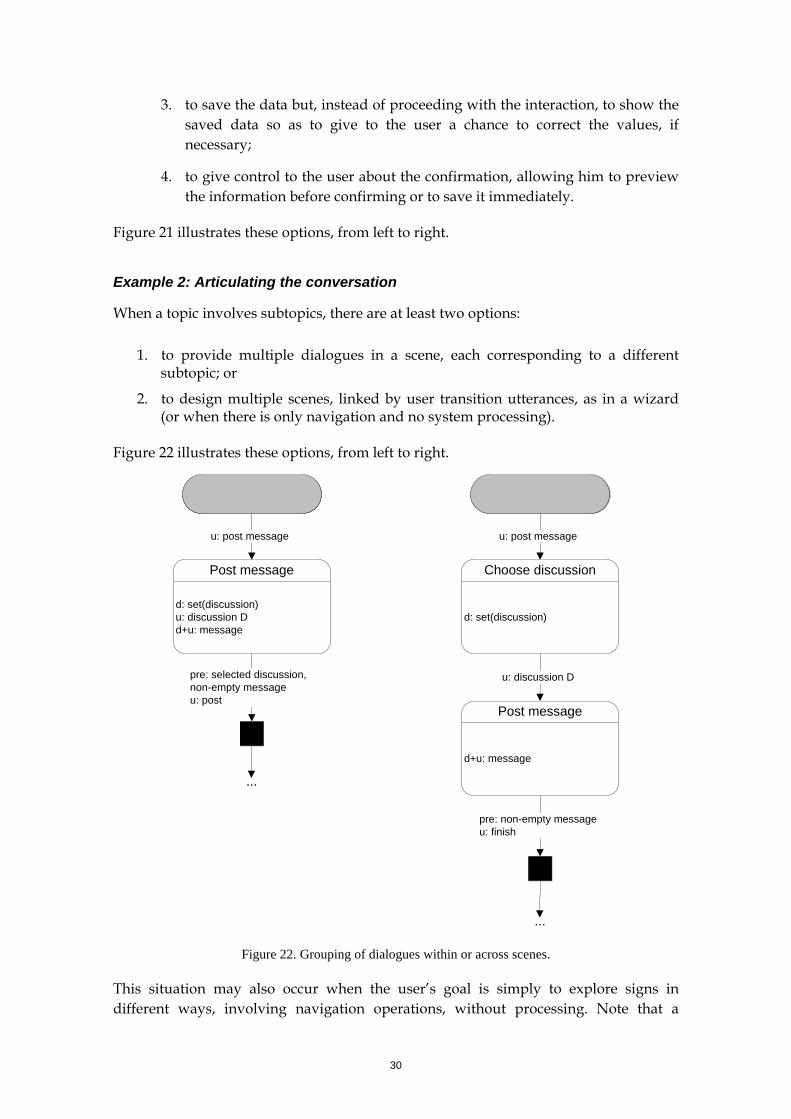
Example 2: Articulating the conversation
When a topic involves subtopics, there are at least two options:
1. to provide multiple dialogues in a scene, each corresponding to a different subtopic; or
2. to design multiple scenes, linked by user transition utterances, as in a wizard (or when there is only navigation and no system processing).
Figure 22 illustrates these options, from left to right.
Post message
d: set(discussion)u: discussion Dd+u: message
u: post message
Choose discussion
d: set(discussion)
u: post message
u: discussion D
Post message
d+u: message
pre: selected discussion, non-empty messageu: post
pre: non-empty messageu: finish
...
...
Figure 22. Grouping of dialogues within or across scenes.
This situation may also occur when the user’s goal is simply to explore signs in different ways, involving navigation operations, without processing. Note that a
31
system process need only be represented when it is paramount to communicate its results to the user. For instance, when there is a change in the conversation topic or in the interaction context (i.e., post conditions). When a user utterance represents only navigation, there is no need to include a system process in between the scenes.
3.2.2 Detailing Dialogues: Second Step in MoLIC Diagram Construction
In this second phase of the interaction design, the designer details the interaction diagram, providing important resources for the implementation of the user interface. Moreover, in this phase, the interaction diagram is complemented by a definition of the signs involved in the dialogues and transition utterances, as will be seen in the next section.
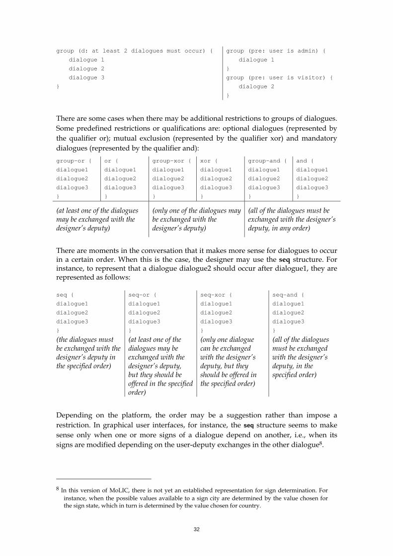
The designer starts detailing the interaction by structuring the dialogues within a scene, the order in which dialogues must occur, whether dialogues are mutually exclusive, and whether the continuation of the conversation depends on the dialogues within a scene.
Dialogue Structure
The representation of the dialogues within a scene so far doesn’t imply a predefined order in which the dialogues must be exchanged. Without any qualifiers, there aren’t any restrictions in the order the dialogues can occur. This is equivalent to the group structure, which simply indicates a grouping of dialogues:
group {
dialogue 1
dialogue 2
}
or simply dialogue 1
dialogue 2
In some conversations, the designer may want to explicitly represent some kind of information about the dialogue group, such as the grouping criteria or restrictions on the corresponding conversation. In the current version of the interaction diagram, such information is provided as free text next to the group keyword and between parentheses: group (grouping criteria or restrictions) {
dialogue 17
dialogue 2
}
If necessary, the grouping criteria and restrictions may be preceded by d:, indicating whether is an explicit communication by the designer’s deputy is intended, or pre: indicating a restriction on the conversation represented by the group.
For instance: 7 Although we use the term “dialogue” here (presuming the d+u: qualifier), everything in this section
applies to designer’s deputy utterances (indicated by d:) as well.
32
group (d: at least 2 dialogues must occur) {
dialogue 1
dialogue 2
dialogue 3
}
group (pre: user is admin) {
dialogue 1
}
group (pre: user is visitor) {
dialogue 2
}
There are some cases when there may be additional restrictions to groups of dialogues. Some predefined restrictions or qualifications are: optional dialogues (represented by the qualifier or); mutual exclusion (represented by the qualifier xor) and mandatory dialogues (represented by the qualifier and): group-or {
dialogue1
dialogue2
dialogue3
}
or {
dialogue1
dialogue2
dialogue3
}
group-xor {
dialogue1
dialogue2
dialogue3
}
xor {
dialogue1
dialogue2
dialogue3
}
group-and {
dialogue1
dialogue2
dialogue3
}
and {
dialogue1
dialogue2
dialogue3
}
(at least one of the dialogues may be exchanged with the designer’s deputy)
(only one of the dialogues may be exchanged with the designer’s deputy)
(all of the dialogues must be exchanged with the designer’s deputy, in any order)
There are moments in the conversation that it makes more sense for dialogues to occur in a certain order. When this is the case, the designer may use the seq structure. For instance, to represent that a dialogue dialogue2 should occur after dialogue1, they are represented as follows: seq {
dialogue1
dialogue2
dialogue3
}
seq-or {
dialogue1
dialogue2
dialogue3
}
seq-xor {
dialogue1
dialogue2
dialogue3
}
seq-and {
dialogue1
dialogue2
dialogue3
}
(the dialogues must be exchanged with the designer’s deputy in the specified order)
(at least one of the dialogues may be exchanged with the designer’s deputy, but they should be offered in the specified order)
(only one dialogue can be exchanged with the designer’s deputy, but they should be offered in the specified order)
(all of the dialogues must be exchanged with the designer’s deputy, in the specified order)
Depending on the platform, the order may be a suggestion rather than impose a restriction. In graphical user interfaces, for instance, the seq structure seems to make sense only when one or more signs of a dialogue depend on another, i.e., when its signs are modified depending on the user-deputy exchanges in the other dialogue8.
8 In this version of MoLIC, there is not yet an established representation for sign determination. For
instance, when the possible values available to a sign city are determined by the value chosen for the sign state, which in turn is determined by the value chosen for country.
33
These structures can be nested, to allow for the representation of more complex scenes.
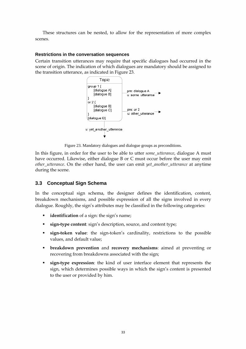
Restrictions in the conversation sequences Certain transition utterances may require that specific dialogues had occurred in the scene of origin. The indication of which dialogues are mandatory should be assigned to the transition utterance, as indicated in Figure 23.
Figure 23. Mandatory dialogues and dialogue groups as preconditions.
In this figure, in order for the user to be able to utter some_utterance, dialogue A must have occurred. Likewise, either dialogue B or C must occur before the user may emit other_utterance. On the other hand, the user can emit yet_another_utterance at anytime during the scene.
3.3 Conceptual Sign Schema
In the conceptual sign schema, the designer defines the identification, content, breakdown mechanisms, and possible expression of all the signs involved in every dialogue. Roughly, the sign’s attributes may be classified in the following categories:
identification of a sign: the sign’s name;
sign-type content: sign’s description, source, and content type;
sign-token value: the sign-token’s cardinality, restrictions to the possible values, and default value;
breakdown prevention and recovery mechanisms: aimed at preventing or recovering from breakdowns associated with the sign;
sign-type expression: the kind of user interface element that represents the sign, which determines possible ways in which the sign’s content is presented to the user or provided by him.
34
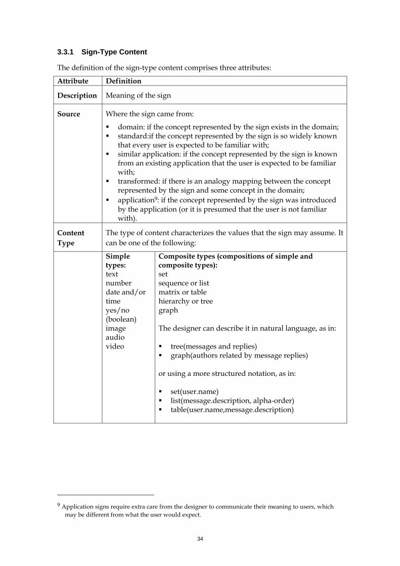
3.3.1 Sign-Type Content
The definition of the sign-type content comprises three attributes:
Attribute Definition
Description Meaning of the sign
Source Where the sign came from:
domain: if the concept represented by the sign exists in the domain; standard:if the concept represented by the sign is so widely known
that every user is expected to be familiar with; similar application: if the concept represented by the sign is known
from an existing application that the user is expected to be familiar with;
transformed: if there is an analogy mapping between the concept represented by the sign and some concept in the domain;
application9: if the concept represented by the sign was introduced by the application (or it is presumed that the user is not familiar with).
Content Type
The type of content characterizes the values that the sign may assume. It can be one of the following:
Simple types: text number date and/or time yes/no (boolean) image audio video
Composite types (compositions of simple and composite types): set sequence or list matrix or table hierarchy or tree graph The designer can describe it in natural language, as in: tree(messages and replies) graph(authors related by message replies)
or using a more structured notation, as in: set(user.name) list(message.description, alpha-order) table(user.name,message.description)
9 Application signs require extra care from the designer to communicate their meaning to users, which
may be different from what the user would expect.
35
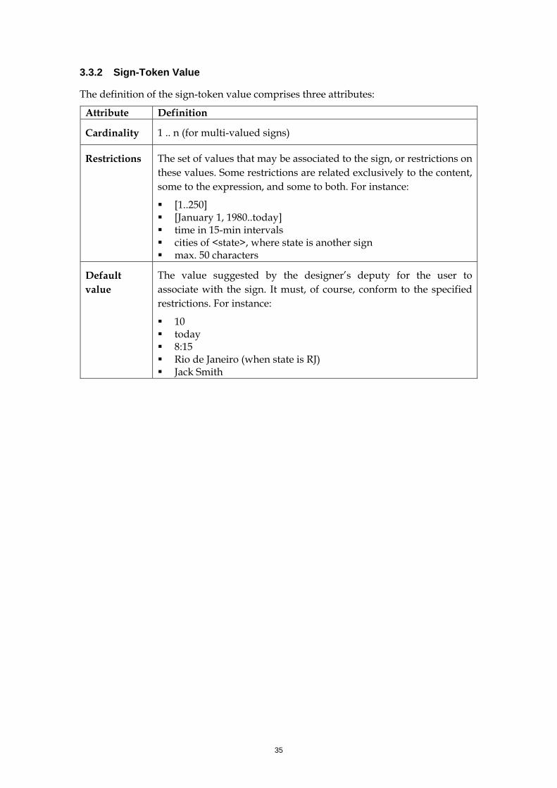
3.3.2 Sign-Token Value
The definition of the sign-token value comprises three attributes:
Attribute Definition
Cardinality 1 .. n (for multi-valued signs)
Restrictions The set of values that may be associated to the sign, or restrictions on these values. Some restrictions are related exclusively to the content, some to the expression, and some to both. For instance:
[1..250] [January 1, 1980..today] time in 15-min intervals cities of <state>, where state is another sign max. 50 characters
Default value
The value suggested by the designer’s deputy for the user to associate with the sign. It must, of course, conform to the specified restrictions. For instance:
10 today 8:15 Rio de Janeiro (when state is RJ) Jack Smith
36
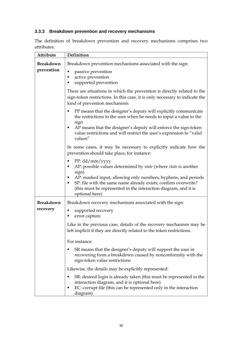
3.3.3 Breakdown prevention and recovery mechanisms
The definition of breakdown prevention and recovery mechanisms comprises two attributes:
Attribute Definition
Breakdown prevention
Breakdown prevention mechanisms associated with the sign:
passive prevention active prevention supported prevention
There are situations in which the prevention is directly related to the sign-token restrictions. In this case, it is only necessary to indicate the kind of prevention mechanism:
PP means that the designer’s deputy will explicitly communicate the restrictions to the user when he needs to input a value to the sign
AP means that the designer’s deputy will enforce the sign-token value restrictions and will restrict the user’s expression to “valid values”
In some cases, it may be necessary to explicitly indicate how the prevention should take place, for instance:
PP: dd/mm/yyyy AP: possible values determined by state (where state is another
sign) AP: masked input, allowing only numbers, hyphens, and periods SP: file with the same name already exists; confirm overwrite?
(this must be represented in the interaction diagram, and it is optional here)
Breakdown recovery
Breakdown recovery mechanisms associated with the sign:
supported recovery error capture
Like in the previous case, details of the recovery mechanism may be left implicit if they are directly related to the token restrictions.
For instance:
SR means that the designer’s deputy will support the user in recovering from a breakdown caused by nonconformity with the sign-token value restrictions
Likewise, the details may be explicitly represented:
SR: desired login is already taken (this must be represented in the interaction diagram, and it is optional here)
EC: corrupt file (this can be represented only in the interaction diagram)
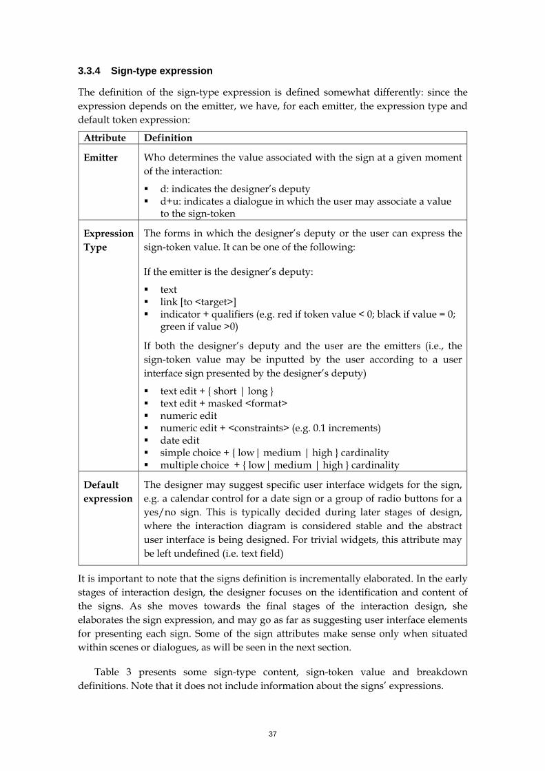
37
3.3.4 Sign-type expression
The definition of the sign-type expression is defined somewhat differently: since the expression depends on the emitter, we have, for each emitter, the expression type and default token expression:
Attribute Definition
Emitter
Who determines the value associated with the sign at a given moment of the interaction:
d: indicates the designer’s deputy d+u: indicates a dialogue in which the user may associate a value
to the sign-token
Expression Type
The forms in which the designer’s deputy or the user can express the sign-token value. It can be one of the following:
If the emitter is the designer’s deputy:
text link [to <target>] indicator + qualifiers (e.g. red if token value < 0; black if value = 0;
green if value >0)
If both the designer’s deputy and the user are the emitters (i.e., the sign-token value may be inputted by the user according to a user interface sign presented by the designer’s deputy)
text edit + { short | long } text edit + masked <format> numeric edit numeric edit + <constraints> (e.g. 0.1 increments) date edit simple choice + { low| medium | high } cardinality multiple choice + { low| medium | high } cardinality
Default expression
The designer may suggest specific user interface widgets for the sign, e.g. a calendar control for a date sign or a group of radio buttons for a yes/no sign. This is typically decided during later stages of design, where the interaction diagram is considered stable and the abstract user interface is being designed. For trivial widgets, this attribute may be left undefined (i.e. text field)
It is important to note that the signs definition is incrementally elaborated. In the early stages of interaction design, the designer focuses on the identification and content of the signs. As she moves towards the final stages of the interaction design, she elaborates the sign expression, and may go as far as suggesting user interface elements for presenting each sign. Some of the sign attributes make sense only when situated within scenes or dialogues, as will be seen in the next section.
Table 3 presents some sign-type content, sign-token value and breakdown definitions. Note that it does not include information about the signs’ expressions.
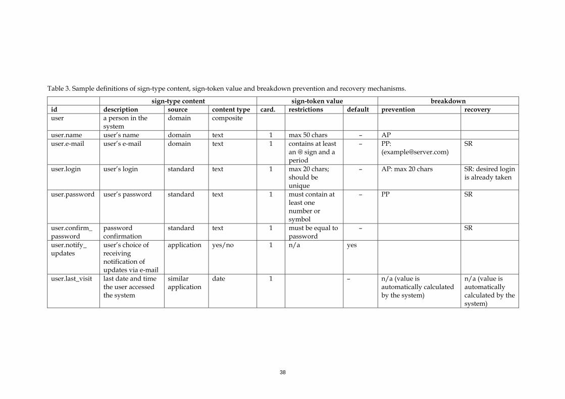
38
Table 3. Sample definitions of sign-type content, sign-token value and breakdown prevention and recovery mechanisms.
sign-type content sign-token value breakdown id description source content type card. restrictions default prevention recovery user a person in the
system domain composite
user.name user’s name domain text 1 max 50 chars – AP user.e-mail user’s e-mail domain text 1 contains at least
an @ sign and a period
– PP: ([email protected])
SR
user.login user’s login standard text 1 max 20 chars; should be unique
– AP: max 20 chars SR: desired login is already taken
user.password user’s password standard text 1 must contain at least one number or symbol
– PP SR
user.confirm_ password
password confirmation
standard text 1 must be equal to password
– SR
user.notify_ updates
user’s choice of receiving notification of updates via e-mail
application yes/no 1 n/a yes
user.last_visit last date and time the user accessed the system
similar application
date 1 – n/a (value is automatically calculated by the system)
n/a (value is automatically calculated by the system)
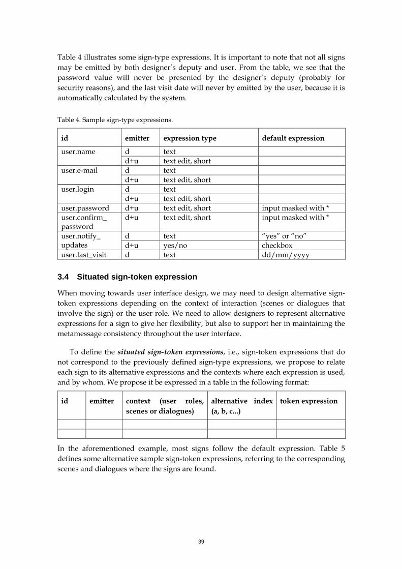
39
Table 4 illustrates some sign-type expressions. It is important to note that not all signs may be emitted by both designer’s deputy and user. From the table, we see that the password value will never be presented by the designer’s deputy (probably for security reasons), and the last visit date will never by emitted by the user, because it is automatically calculated by the system.
Table 4. Sample sign-type expressions.
id emitter expression type default expression
d text user.name d+u text edit, short d text user.e-mail d+u text edit, short d text user.login d+u text edit, short
user.password d+u text edit, short input masked with * user.confirm_ password
d+u text edit, short input masked with *
d text “yes” or “no” user.notify_ updates d+u yes/no checkbox user.last_visit d text dd/mm/yyyy
3.4 Situated sign-token expression
When moving towards user interface design, we may need to design alternative sign-token expressions depending on the context of interaction (scenes or dialogues that involve the sign) or the user role. We need to allow designers to represent alternative expressions for a sign to give her flexibility, but also to support her in maintaining the metamessage consistency throughout the user interface.
To define the situated sign-token expressions, i.e., sign-token expressions that do not correspond to the previously defined sign-type expressions, we propose to relate each sign to its alternative expressions and the contexts where each expression is used, and by whom. We propose it be expressed in a table in the following format:
id emitter context (user roles, scenes or dialogues)
alternative index (a, b, c...)
token expression
In the aforementioned example, most signs follow the default expression. Table 5 defines some alternative sample sign-token expressions, referring to the corresponding scenes and dialogues where the signs are found.
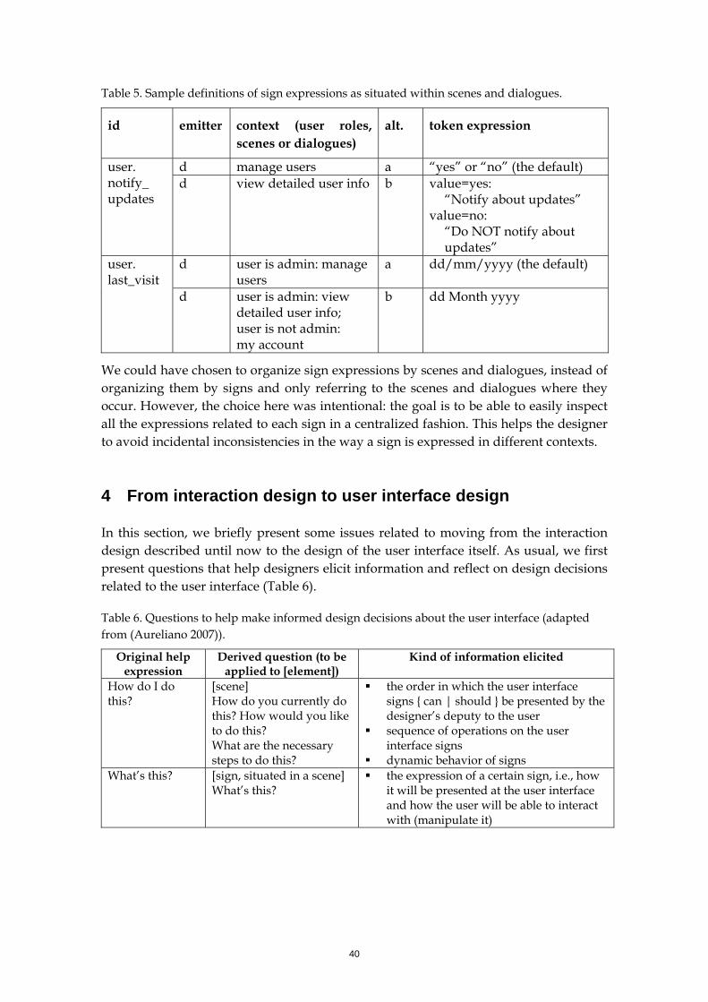
40
Table 5. Sample definitions of sign expressions as situated within scenes and dialogues.
id emitter context (user roles, scenes or dialogues)
alt. token expression
d manage users a “yes” or “no” (the default) user. notify_ updates
d view detailed user info b value=yes: “Notify about updates”
value=no: “Do NOT notify about updates”
d user is admin: manage users
a dd/mm/yyyy (the default) user. last_visit
d user is admin: view detailed user info; user is not admin: my account
b dd Month yyyy
We could have chosen to organize sign expressions by scenes and dialogues, instead of organizing them by signs and only referring to the scenes and dialogues where they occur. However, the choice here was intentional: the goal is to be able to easily inspect all the expressions related to each sign in a centralized fashion. This helps the designer to avoid incidental inconsistencies in the way a sign is expressed in different contexts.
4 From interaction design to user interface design
In this section, we briefly present some issues related to moving from the interaction design described until now to the design of the user interface itself. As usual, we first present questions that help designers elicit information and reflect on design decisions related to the user interface (Table 6).
Table 6. Questions to help make informed design decisions about the user interface (adapted from (Aureliano 2007)).
Original help expression
Derived question (to be applied to [element])
Kind of information elicited
How do I do this?
[scene] How do you currently do this? How would you like to do this? What are the necessary steps to do this?
the order in which the user interface signs { can | should } be presented by the designer’s deputy to the user
sequence of operations on the user interface signs
dynamic behavior of signs What’s this? [sign, situated in a scene]
What’s this? the expression of a certain sign, i.e., how
it will be presented at the user interface and how the user will be able to interact with (manipulate it)
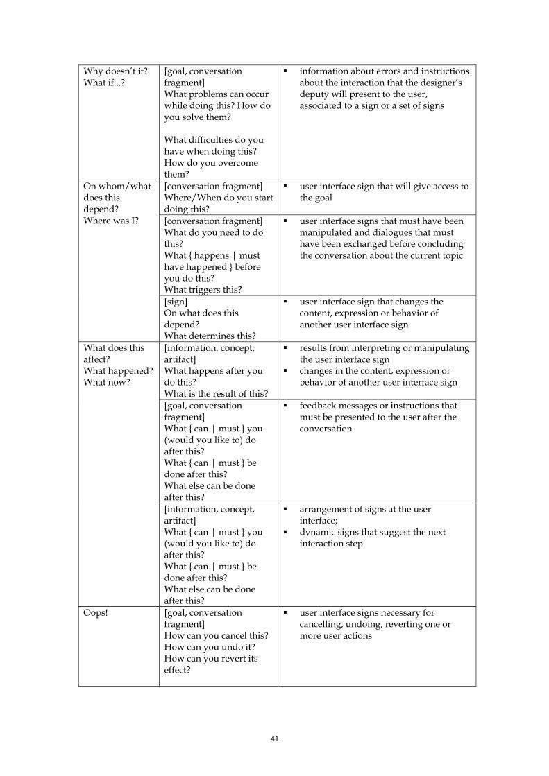
41
Why doesn’t it? What if...?
[goal, conversation fragment] What problems can occur while doing this? How do you solve them? What difficulties do you have when doing this? How do you overcome them?
information about errors and instructions about the interaction that the designer’s deputy will present to the user, associated to a sign or a set of signs
[conversation fragment] Where/When do you start doing this?
user interface sign that will give access to the goal
[conversation fragment] What do you need to do this? What { happens | must have happened } before you do this? What triggers this?
user interface signs that must have been manipulated and dialogues that must have been exchanged before concluding the conversation about the current topic
On whom/what does this depend? Where was I?
[sign] On what does this depend? What determines this?
user interface sign that changes the content, expression or behavior of another user interface sign
[information, concept, artifact] What happens after you do this? What is the result of this?
results from interpreting or manipulating the user interface sign
changes in the content, expression or behavior of another user interface sign
[goal, conversation fragment] What { can | must } you (would you like to) do after this? What { can | must } be done after this? What else can be done after this?
feedback messages or instructions that must be presented to the user after the conversation
What does this affect? What happened? What now?
[information, concept, artifact] What { can | must } you (would you like to) do after this? What { can | must } be done after this? What else can be done after this?
arrangement of signs at the user interface;
dynamic signs that suggest the next interaction step
Oops! [goal, conversation fragment] How can you cancel this? How can you undo it? How can you revert its effect?
user interface signs necessary for cancelling, undoing, reverting one or more user actions
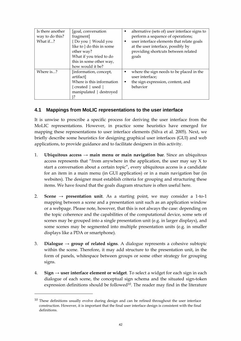
42
Is there another way to do this? What if...?
[goal, conversation fragment] { Do you | Would you like to } do this in some other way? What if you tried to do this in some other way, how would it be?
alternative (sets of) user interface signs to perform a sequence of operations;
user interface elements that relate goals at the user interface, possibly by providing shortcuts between related goals
Where is...? [information, concept, artifact] Where is this information { created | used | manipulated | destroyed }?
where the sign needs to be placed in the user interface;
the sign expression, content, and behavior
4.1 Mappings from MoLIC representations to the user interface
It is unwise to prescribe a specific process for deriving the user interface from the MoLIC representations. However, in practice some heuristics have emerged for mapping these representations to user interface elements (Silva et al. 2005). Next, we briefly describe some heuristics for designing graphical user interfaces (GUI) and web applications, to provide guidance and to facilitate designers in this activity.
1. Ubiquitous access → main menu or main navigation bar. Since an ubiquitous access represents that “from anywhere in the application, the user may say X to start a conversation about a certain topic”, every ubiquitous access is a candidate for an item in a main menu (in GUI applicatios) or in a main navigation bar (in websites). The designer must establish criteria for grouping and structuring these items. We have found that the goals diagram structure is often useful here.
2. Scene → presentation unit. As a starting point, we may consider a 1-to-1 mapping between a scene and a presentation unit such as an application window or a webpage. Please note, however, that this is not always the case: depending on the topic coherence and the capabilities of the computational device, some sets of scenes may be grouped into a single presentation unit (e.g. in larger displays), and some scenes may be segmented into multiple presentation units (e.g. in smaller displays like a PDA or smartphone).
3. Dialogue → group of related signs. A dialogue represents a cohesive subtopic within the scene. Therefore, it may add structure to the presentation unit, in the form of panels, whitespace between groups or some other strategy for grouping signs.
4. Sign → user interface element or widget. To select a widget for each sign in each dialogue of each scene, the conceptual sign schema and the situated sign-token expression definitions should be followed10. The reader may find in the literature
10 These definitions usually evolve during design and can be refined throughout the user interface
construction. However, it is important that the final user interface design is consistent with the final definitions.
43
about user interface design numerous guides on widget selection for different environments (GUI, web, PDAs, and so on), so we will not elaborate on this here.
5. User transition utterance → button or link. When a user transition utterance representing a change in topic leads to a system processing, it is typically mapped on to a command button. When it leads to another scene, it corresponds to a navigation operation, and it is typically mapped as a link, especially in websites. In GUI applications, navigation operations are also often mapped on to buttons. It is important to note that these buttons or links should typically be located at a standard position across all presentation units. However, when the utterance is more closely related to a specific subtopic (dialogue), the corresponding button or link can be located within the corresponding group of signs.
6. Designer’s deputy transition utterance → separate presentation unit or feedback within a presentation unit. In GUI applications, the designer’s deputy transition utterance is typically designed as message boxes or as a change in the status bar text. When the result is trivial and expected by the user, it may be mapped onto the status bar. However, when it is important to call attention to the user, it is typically designed as a message box that the user must acknowledge to continue to use the application. In web applications, the time delay to fetch a webpage on the server encourages the representation of the designer’s deputy transition utterance as a message within the “next” page, instead of having a webpage devoted exclusively to the feedback.
7. Designer’s deputy monologue → presentation unit. A designer’s deputy monologue is a particular case of feedback, which closes a conversation thread, and thus should be mapped on to a dedicated presentation unit, either in GUI or web applications.
8. Supported recovery mechanisms → error messages. To support the user in recovering from a breakdown, the user interface must adequately state that a problem has occurred, what the problem was, its probable cause (if not trivial), and how the user can correct it (also if not trivial). This feedback may be designed both as a message box and as individual error messages for each problem that has occurred. It is important that the user has easy access to the error messages and recovery instructions where he is supposed to correct them (e.g. help messages next to incorrect form fields).
9. Passive prevention mechanisms → contextualized instructions. Whenever a sign has an associated passive prevention mechanism, every presentation unit that allows the user to attribute a value to the sign should present the passive prevention text next to the sign.
10. Preconditions → activating/deactivating or showing/hiding user interface elements. Preconditions in user transition utterances are usually mapped onto the behavior of activating/deactivating buttons or links that correspond to the utterance. It may be the case, however, that the precondition can never be satisfied
44
by the current user (e.g. a “user is admin” precondition). In this case, it may be better to hide the corresponding user interface element altogether, so that the user will not become frustrated in attempting to do something to activate it.
This set of heuristics is by no means exhaustive, but they give a general idea on how to use the various MoLIC artifacts in designing the user interface. It is not sufficient to follow these heuristics, however. We do strongly recommend designers to use one or more formative evaluation methods throughout the user interface design, in addition to all the material provided in this document.
5 Concluding Remarks
This document presented a practical guide to the construction of MoLIC artifacts. It is intended as an instructional material not only for interaction modeling, but mostly for supporting designers in reflecting on the problems at hand and on the possible solutions and their implications. In grounding MoLIC in semiotic engineering, we have the benefit of being able to reflect on the interaction from either the user or the deputy’s perspective, and to switch perspectives to further explore the design problem and solution spaces.
In addition, this document have also provided some guidance for the design of the user interface itself. It does not intend to be a definitive guide on this matter, but to help readers understand the impact of the decisions made during the construction of MoLIC artifacts.
MoLIC is under constant revision. If you have any suggestions or comments, please contact the authors.
45
References
AURELIANO, V. C. O., eXtreme Communication-Centered Design: um processo ágil para o projeto da interação humano-computador, Dissertação de mestrado, Departamento de Informática, PUC-Rio, 2007.
BARBOSA, S.D.J.; PAULA, M.G.: Designing and Evaluating Interaction as Conversation: a Modeling Language based on Semiotic Engineering. In 10th International Workshop on Design, Specification and Verification of Interactive Systems, DSV-IS 2003, Funchal, Madeira Island, Portugal, Junho 11-13, 2003, Revised Papers Series: Lecture Notes in Computer Science, Vol. 2844 2003, XIII, 429 p. ISBN: 3-540-20159-9. p. 16–33.
CARROLL, J. M. (ed.). Scenario-based design: envisioning work and technology in system development. New York , John Wiley and Sons, Inc. 1995.
CARROLL, J. M. (ed) Making use: Scenario-Based Design of Human-Computer Interactions. The MIT Press. Cambridge, MA, 2000.
de SOUZA, C. S. The Semiotic Engineering of Human-Computer Interaction. The MIT Press 2005.
DIAPER, D. & STANTON, N. (eds.) The handbook of task analysis for human-computer interaction, Mahwaw, NJ: Lawrence Erlbaum Associates, 2004.
HOOVER, S.; RINDERLE, J.; FINGER, S. Models and Abstractions in Design. Design Studies. Volume 12, Number 4, October, 1991.
HUTCHBY, I. & WOOFFITT, R. Conversation Analysis: Principles, Practices and Applications. Polity Press, 1998.
KIRSH, D.; MAGLIO, P.: On distinguishing epistemic from pragmatic action. Cognitive Science 18: 513:549. 1995
PATERNÒ, F. Model-Based Design and Evaluation of Interactive Applications, London, Springer-Verlag, 2000.
PAULA, M. G., Projeto da interação humano-computador baseado em modelos fundamentados na engenharia semiótica: construção de um modelo de interação, Dissertação de mestrado, Departamento de Informática, PUC-Rio, 2003.
PAULA, M. G.; SILVA, B. S.; BARBOSA, S. D. J. Using an Interaction Model as a Resource for Communication in Design. Proceedings of CHI 2005, Extended abstracts volume. Portland, OR, USA, 2005.
PUERTA, A. R.: A Model-Based Interface Development Environment. IEEE Software, July/August, pp. 40-47, 1997.
SCHÖN, D.A. The Reflective Practitioner. New York, NY: Basic Books. 1983.
SILVA, B. S., MoLIC Segunda Edição: revisão de uma linguagem para modelagem da interação humano-computador. Dissertação de Mestrado, Departamento de Informática, PUC-Rio, Rio de Janeiro, Brasil. Agosto de 2005.
46
SILVA, B. S.; BARBOSA, S. D. J., Modelando a Interação do Nita: um estudo de caso e extensões ao MoLIC. VI Simpósio sobre Fatores Humanos em Sistemas Computacionais, IHC 2004. Curitiba, outubro de 2004.
SILVA, B. S.; NETTO, O. A M.; BARBOSA, S. D. J.: Promoting a Separation of Concerns via Closely-Related Interaction and Presentation Models. In Proceedings of Second Latin American Conference on Human-Computer Interaction, CLICHC 2005, Cuernavaca, Mexico, October, 2005.
SILVEIRA, M. S., Metacomunicação Designer-Usuário na Interação Humano-Computador: design e construção do sistema de ajuda. Tese de Doutorado, Departamento de Informática, PUC-Rio, Rio de Janeiro Brasil. 2002.
VANDERDONCKT, J.; BERQUIN, P.: Towards a Very Large Model-based Approach for User Interface Development, in Proc. of 1st Int. Workshop on User Interfaces to Data Intensive Systems UIDIS’99 (Edinburg, 5-6 September 1999), N.W. Paton & T. Griffiths (eds.), IEEE Computer Society Press, Los Alamitos, pp. 76-85, 1999.
WINOGRAD, T.; FLORES, F. Understanding Computers and Cognition. Reading, MA: Addison-Wesley. 1986